comparisons between usdc (is-54) and gsm division multiple access (tdma/fdd) / frequency division...
TRANSCRIPT

Naresuan University Journal 2004; 12(3): 75-93 75
Comparisons Between USDC (IS-54) and GSM
Surachet Kanprachar
Department of Electrical and Computer Engineering, Faculty of Engineering,Naresuan University, Phitsanulok 65000, Thailand.Corresponding author. E-mail address: [email protected] (S. Kanprachar)Received 29 April 2004; accepted 8 November 2004
________________________________________________________________________________________
SummaryUnited States Digital Cellular (USDC) system and Global System for Mobile
Communication (GSM) are two main standards of the second generation of digital wireless telephonesystem. Both of them have similarities and differences. In this paper many important characteristicsof these two standards are discussed. The details of USDC and GSM are investigated. Focusing onthe modulation types, the effect of pulse shapings, Bit-Error-Rate (BER), and spectral efficiencywill be compared by using computer graphic analysis. USDC has better performances than GSM interms of zero intersymbol interference (ISI) condition and spectral efficiency. However, there is oneadvantage of GSM over USDC; that is, the power efficiency. Both of them have the same character-istic of BER over a Gaussian channel.
________________________________________________________________
IntroductionThe second generation of wireless cellular telephone was issued to
increase the capacity, improve performance, and add some new services to theprevious analog system. To achieve these goals, the digital techniques areemployed. There are many standards supporting this requirement. Two of themare United States Digital Cellular (USDC) system Interim Standard-54 (IS-54),which was issued for North America, and Global System for MobileCommunication (GSM), which was issued for Europe. Comparing these twostandards, there are some similarities and differences.
USDC and GSM use the same multiple access technique; that is,Time Division Multiple Access (TDMA/FDD) / Frequency Division Duplex (FDD)while there are many differences between them such as themodulation type, frame structure, speech coding etc. In this paper, somecharacteristics of these two standards will be studied intensively. In the followingsections, the details of USDC and GSM will be investigated. These two standardsuse different types of modulation. Because of these different modulation types,some characteristics of these two standards are different. The effect of pulseshapings, Bit-Error-Rate (BER), and spectral efficiency will be compared.The comparisons are based on the computer graphic analysis using the informationfrom the previous sections.
The US Digital Cellular System (USDC)The US digital cellular system (USDC) is also known as Digital Advance
Mobile Phone Service (D-AMPS ) because it was designed to use thesame channel allocations, frequency reuse plan, and base stations as

76 Naresuan University Journal 2004; 12(3)
Advance Mobile Phone Service (AMPS ), which is the first generation analogsystem. However, USDC, which is the second generation of the cellular system inthe US, needs to increase capacity, improve the performance, and add, if possible,new innovative services (in addition to the telephone) (Feher, 1991), so the digitaltechnology is adopted to support these requirements. The entiretransmission standard for USDC is Interim Standard 54 (IS-54), which wasaccepted by the Electronic Industry Association and Telecommunication IndustryAssociation (EIA/TIA) on 1990 (Goodman, 1991). IS-54 is the dual modesystem standard that allows both AMPS and USDC services to be offered in thesame network; that is, the dual mode system. The general description for USDC isfocused on this section. Also, the digital modulation type of USDC is studied.
Frequency allocation and channel bandwidthAs mentioned previously, the USDC uses the same channel allocations as
AMPS; therefore, the reverse channel frequency band for USDC is from 824 to849 MHz, and the forward channel frequency band for USDC is from 869 to 894MHz. The frequency spacing between the reverse and forward channels is 45MHz. Each channel covers the bandwidth of 30 kHz. There are 832channels in total. The control channels for USDC are analog control channels, asused in AMPS (Raith and Uddenfeldt, 1991).
Multiple accessDuplexing in USDC is Frequency Division Duplexing (FDD), which
provides two distinct bands of frequencies for every user. In USDC, these twodistinct bands are 45 MHz apart, as described above. Time Division MultipleAccess (TDMA) is the multiple access method for USDC. USDC divides thechannel bandwidth into time slots. Each time slot is allowed for the user to transmitor receive the signal. Since each channel bandwidth is divided into time slots, manyusers can be supported by one channel bandwidth; thus, the capacity of the systemis increased. Each channel bandwidth of USDC can support up to 6 users withhalf-rate speech coder of 3.975 kbps/user (Rappaport, 1996).
Frame structureIn USDC, six time slots are combined to be one TDMA frame of 40 ms
frame duration, as shown in Figure 1. Each time slot covers 6.67 ms of timeduration. One frame of USDC contains 1944 bits (Goodman, 1991), thus, the datarate is 48.6 kbps. One time slot carries 324 bits including 260 bits of userinformation and 12 bits of system control information or slow associated controlchannel (SACCH). The remaining 52 bits carry 28 bits of time synchronization(SYNC), 12 bits of digital verification color code (DVCC). In the mobile-to-basestation time slot, the remaining 12 bits are a 6-bit guard time interval, when noenergy is transmitted, followed by a 6-bit ramp interval to allow the transmitter toreach its full output power level. In the base station-to-mobile time slot, these 12remaining bits are reserved for future use (RSVD).

Naresuan University Journal 2004; 12(3) 77
G6
R6
DATA16
S Y N C28
DATA122
S A C C H12
D V C C12
DATA122
SLOT 1 SLOT 2 SLOT 3 SLOT 6SLOT 5SLOT 4
S Y N C28
S A C C H12
DATA130
D V C C12
DATA130
R S V D12
1944 bits in 40 ms (48600 b/s)F R A M E
mobile to base stat ion
base stat ion to mobile
G: Guard Time, R: Ramp TimeDVCC: Digital Verif icat ion Color CodeRSVD: Reserved for Future Use
Figure 1 IS-54 slot and frame structure (Goodman, 1991)
The user information bits are divided into two 122-bit data block and one16-bit data block, in mobile-to-base station direction. In base station-to-mobiledirection, the information bits are divided into two 130-bit data block. The slowassociated control channel (SACCH) is sent in every time slot, providinga signaling channel parallel with the digital speech. The mobile assisted handoff(MAHO) is also supported by SACCH; that is, SACCH from mobile unit reportsthe results of signal strength measurements of neighboring base stations. Whenthe received power from the base station of a neighboring base station begins toexceed the received power from the current base station by a certain value or fora certain period of time, the handoff is initiated (Rappaport, 1996).
The 28-bit of synchronization signal contains a known bit pattern thatallows the receiver to establish bit synchronism and to train an adaptive equalizer(Goodman, 1991). Six different synchronization patterns are specified by thesystem, one for each time slot in the TDMA frame. The digital verification colorcode (DVCC) is a 12-bit message, which is sent in every time slot. There are 256color codes generated by 8 bits. These color codes are protected by (12,8)Hamming code; thus, DVCC contains 12 bits. One of these codes is assigned toeach base station to prevent a receiver from locking onto an interfering signal froma distance cell.
Speech codingThe speech coding adopted for USDC is a vector-sum excited linear
predictive coder (VSELP). This speech coder belongs to the class of code excitedlinear predictive coder (CELP) (Rappaport, 1996). The block diagram of the VSELP
78 Naresuan University Journal 2004; 12(3)
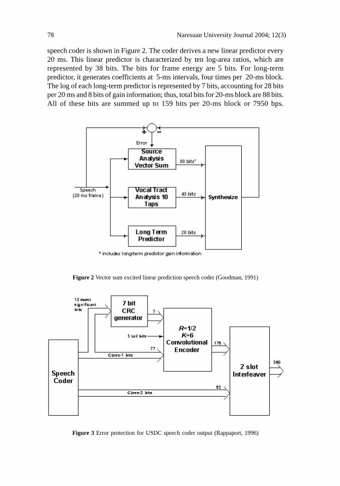
speech coder is shown in Figure 2. The coder derives a new linear predictor every20 ms. This linear predictor is characterized by ten log-area ratios, which arerepresented by 38 bits. The bits for frame energy are 5 bits. For long-termpredictor, it generates coefficients at 5-ms intervals, four times per 20-ms block.The log of each long-term predictor is represented by 7 bits, accounting for 28 bitsper 20 ms and 8 bits of gain information; thus, total bits for 20-ms block are 88 bits.All of these bits are summed up to 159 bits per 20-ms block or 7950 bps.
Figure 2 Vector sum excited linear prediction speech coder (Goodman, 1991)
Figure 3 Error protection for USDC speech coder output (Rappaport, 1996)

Naresuan University Journal 2004; 12(3) 79
Channel codingThe output bits of the VSELP speech coder are divided into two groups;
one is 77 class-1 bits and the other is 82 class-2 bits. The 77 class-1 bits havea greater influence on speech quality than the 82 class-2 bits; therefore, these77 class-1 bits are protected by an error detecting code and a rate ½ convolutional code to produce a sequence of 178 bits, as shown in Figure 3. Thetwelve most significant bits of class-1 bit are block coded using a 7-bit CRC errordetection code (Rappaport, 1996) to generate output of 7 bits. These 7 bits outputfrom CRC generator, 5 tail bits, and 77 class-1 bits are sent to a rate ½ convolutional encoder using constraint length K of 6. The 178 bits output of theconvolutional encoder and 82 class-2 bits are multiplexed together producing 260transmitted bits. Two blocks of 260 channel bits are interleaved and placed into thetwo assigned time slots of the 40-ms transmission frame (Goodman, 1991).
Modulation techniqueIn USDC, π/4 DQPSK modulation technique has been adopted. This type
of modulation was first proposed for data transmission via telephone lines by Bakerof Bell Telephone Laboratories (Feher, 1991). A π/4 DQPSK is used with 0.35rolloff raised cosine filtering to transmit the gross data of 4.6 kbps within 30 kHzchannel bandwidth. Since it is differentially encoded at the transmitter, the detectorof this modulation type can be coherent, differential, or discrimination detector.Certainly, on the receiver side, there must be a raised cosine filter that matchesthat of the transmitter side for satisfaction of zero intersymbol interference (ISI)condition.
D a taS o u rce
S er ia lto
P ara lle lC on verter
S ig n a lM ap p in g
L P F
L P F
Σ A m p .
S I
S Q
Ik
Q k
co s(ωc t)
-sin (ωc t)
s (t)I(t)
Q ( t)
Figure 4 Block diagram of the transmitter of π/4 QPSK modulator (Yacoub, 1993)
The block diagram of π/4 QPSK is shown in Figure 4. Note that thetransmitters of π/4 DQPSK and π/4 QPSK are identical except that the input databits for π/4 DQPSK are differential encoded. Thus, in this section, the operation ofπ/4 QPSK is considered. The binary data are first converted to two parallel datastreams referring to SI and SQ. Then, these two data are mapped by the signalmapping circuit to be the in-phase (Ik) and quadrature (Qk) pulse amplitudes. These
80 Naresuan University Journal 2004; 12(3)
pulse amplitudes are determined from their previous values (Ik-1 and Qk-1) andan absolute phase angle (θk) (Rappaport, 1996), as shown in equation (1) and (2).The absolute phase angle (θk) for the symbol kth is a function of its previous value(θk-1) and a phase shift (φk), which is a function of the current input data(SI and SQ).
kkQkkIkkI φφθ sin1cos1cos −−−== (1)
kkQkkIkkQ φφθ cos1sin1sin −+−== (2)
kkk φθθ +−= 1 (3)
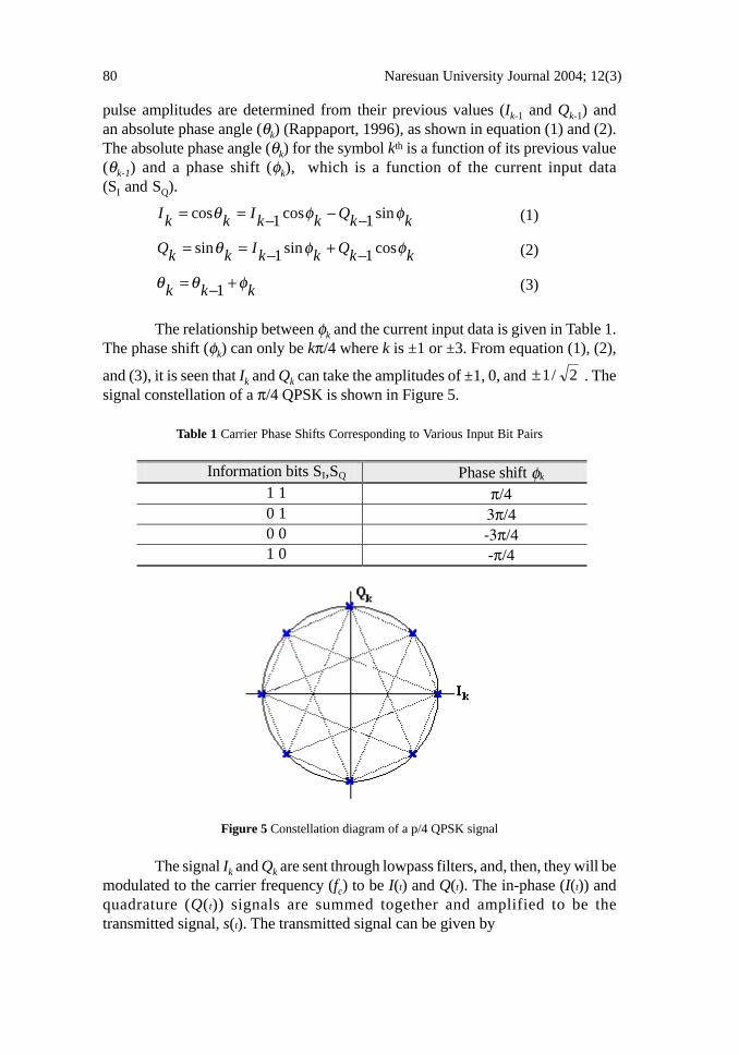
The relationship between φk and the current input data is given in Table 1.The phase shift (φk) can only be kπ/4 where k is ±1 or ±3. From equation (1), (2),
and (3), it is seen that Ik and Qk can take the amplitudes of ±1, 0, and 2/1± . Thesignal constellation of a π/4 QPSK is shown in Figure 5.
Table 1 Carrier Phase Shifts Corresponding to Various Input Bit Pairs
Figure 5 Constellation diagram of a p/4 QPSK signal
The signal Ik and Qk are sent through lowpass filters, and, then, they will bemodulated to the carrier frequency (fc) to be I(t) and Q(t). The in-phase (I(t)) andquadrature (Q(t)) signals are summed together and amplified to be thetransmitted signal, s(t). The transmitted signal can be given by
Information bits SI,SQ Phase shift φk 1 1 π/4 0 1 3π/4 0 0 -3π/4 1 0 -π/4

Naresuan University Journal 2004; 12(3) 81
tctQtctIts ωω sin)(cos)()( −= (4)
It is seen that the information in a π/4 QPSK signal is contained in thephase difference φk of the carrier between two adjacent symbols. At the receiverthe phase difference between two sampling instants is needed only; thus, thedifferential detection can be employed.
In USDC, the raised cosine pulse shaping is adopted with a rolloff factorof 0.35. This type of pulse shaping satisfies the zero ISI condition. The raisedcosine rolloff transfer function can be achieved by using identical )( fRCH
filters at the transmitter and receiver sides. The expression for this filter is shownin equation (5) and (6) below (Rappaport, 1996).
Frequency domain:
⎜⎜⎜⎜⎜⎜
⎝
⎛
⎥⎥⎦
⎤
⎢⎢⎣
⎡
⎟⎟
⎠
⎞⎜⎜
⎝
⎛
+>
+≤<−+−
+
−≤≤
=
sTf
sTfsTf
sT
sTf
fRCH
2/)1(; 0
2/)1(2/)1(; 2
]1)2[(cos1
2
1
2/)1(0; 1
)(
α
ααα
απ
α
(5)
where α is the rolloff factor which ranges between 0 and 1.Ts is the symbol period.
Time domain:
⎟⎠⎞⎜
⎝⎛=
)/sin()(
tsTt
tRChππ
(6)
The power spectral density of Quadrature Phase Shift Key (QPSK)signal depends on the power spectral density of the pulse shaping function. ForQPSK, there are four possible signals to be transmitted. The probabilities ofsending these signals are identical. Thus, the power spectral density of QPSKsignal is the same profile as the power spectral density of the pulse shapingfunction except the center frequencies are shifted to be at ±fc. The differentialencoding does not modify the power spectral density, so the power spectral densityof a Differential Quadrature Phase Shift Key (DQPSK) signal is the same as thatof a QPSK signal (Couch, 2001).
⎟⎟⎠
⎞⎜⎜⎝
⎛⎟⎠⎞
− 2))2/(4(1
)/cos()
sTt
sTt
α
πα

82 Naresuan University Journal 2004; 12(3)
Since π/4 DQPSK can be detected by using coherent detection ordifferential detection, the bit error probability calculation of it is divided into twocases. One is for coherent detection, the bit error calculation is shown in equation(7) (Couch, 2001). For a differential detection, the bit error probability calculationis also shown in equation (9) (Couch, 2001). These two equations are for the signalwith Gray coding over a Gaussian channel.
Coherent detection:
⎭⎬⎫
⎩⎨⎧
=0
2
N
EQP b
b (7)
where
{ } ∫∞ −
⎟⎠⎞⎜
⎝⎛==
x
y xerfcdyexQ
22
1
2
1 2
2
π (8)
Differential detection:
∫∞ +
−= ⎟⎟⎠
⎞⎜⎜⎝
⎛
bI
xaxbP
2
22exp
(9)
where I0(·) is the modified Bessel function of order zero and
⎟⎠⎞⎜⎝
⎛ −−+= 22222 0N
Ea b
(10)
⎟⎠⎞⎜⎝
⎛ −++= 22222 0N
Eb b
(11)
Eb is the energy contained in one bit periodN0 is the noise power
For the fading channel, the bit error probability calculation of the QPSK isgiven by equation (12). This equation is for the slow fading channel. Equation (13)is the expression for finding the bit error probability of a DQPSK signal in the fastfading channel (Couch, 2001). These two equations will be plotted and discussedin the last section.
+−− ⎟⎠⎞⎜
⎝⎛
⎟⎟⎠
⎞IbadxabI )22(
2
1exp
2
1)(0 ⎟
⎠⎞
abI )(0)
Naresuan University Journal 2004; 12(3) 83
QPSK (slow fading):
⎪⎭
⎪⎬⎫
⎪⎩
⎪⎨⎧
⎟⎟⎠
⎞⎜⎜⎝
⎛+
−−−=2
0
0 )/1
/1(
2
111
3
2
NE
NEP
b
bb (12)
DQPSK (fast fading):
⎪⎭
⎪⎬⎫
⎪⎩
⎪⎨⎧
⎟⎠⎞⎜
⎝⎛ −−−=
2
)1(2
11`1
3
2FPb (13)
where
)2())/(1(2
)2(2
021
0
0
TfJNE
TfJF
Db
D
π
π
−+=
− (14)
J0(·) is the zeroth-order Besssel function of the first kindJ0(2πfDT) is the normalized envelope correlationfD is the maximum Doppler frequency.
The Global System of Mobile Communication (GSM)
Frequency allocation and channel bandwidthThe Global System of Mobile communications (GSM) is a digital cellular
communication system initially developed in a European. For GSM-900 system,two frequency bands have been made available; that is, 890 - 915 MHz for uplink(direction to Mobile Station (MS) to Base Station (BS) and 935 - 960 MHz fordownlink (direction BS to MS). By using Frequency Division Multiple Access(FDMA), the bandwidth of 25 MHz is divided into 124 pairs of frequency duplexchannels with 200 kHz carrier spacing and duplex spacing of 45 MHz betweenuplink and downlink directions. A guard band of 200 kHz is left between thebottom edge of each band and the first RF carrier. The carrier frequencies in thetwo bands for nth duplex radio channel will be 890.2 + 0.2(n - 1) MHz for uplinkand 935.2 + 0.2(n - 1) MHz for downlink.
Multiple accessTime Division Multiple Access is used to split a 200 kHz radio channel into
8 time slots. In other word, it creates 8 logical channels. Each channel transmitsthe digitized speech in a series of short bursts, so a GSM terminal is onlytransmitting for one eighth of the time. The 8-slot TDMA together with 124physical full duplex channels corresponds to total 992 logical full duplex channels.

84 Naresuan University Journal 2004; 12(3)
Frame structureThe GSM system distinguishes between traffic channels and control
channels. Traffic Channel/Full-Rate Speech (TCH/FS) is used to carry speech atthe speed of 13 kbps. In the TCH, data are transmitted in bursts (148 bits), whichare placed in time slots. The 8.25 bit guard time allows for some propagation timedelay in the arrival of bursts. A total of 156.25 bits is transmitted in 0.577milliseconds (bit period 3.79 microseconds), giving a gross bit rate of 270.833 kbps.Eight bursts of eight users are multiplexed onto one RF carrier giving a TDMAframe of 8 x 0.577 ms ≈ 4.615 ms. The effective information throughput is114/4.615 ms ≈ 24.7 kbps which is sufficiently high to transmit TCH/FS.
Figure 6 The TDMA frame structure of GSM system (Raith and Uddenfeldt, 1991)
The TDMA frame of eight users are multiplexed together into multiframesof 24 TDMA frames, but the 13th will carry a Slow Associated Control Channel(SACCH) message, while the 26th will be an idle or dummy frame. The 24TCH/FS frames are sent in a multiframe during 26 x 4.615 ms ≈ 120 ms. Thetraffic throughput is reduced to 24/26 x 24.7 kbps ≈ 22.8 kbps.
Speech codingThe full rate speech codec in GSM is described as Regular Pulse
Excitation with Long Term Prediction (GSM 06.10 RPE-LTP). The encoderdivides the speech into short-term predictable parts, long predictable parts and theremaining residual pulse. Then, it encodes that pulse and parameters for the twopredictors. Information from previous samples, which does not change very quickly,is used to predict the current sample. The coefficients of the linear combinations ofthe previous samples, plus the encoded form of the residual, the differencebetween the predicted and actual sample represent the signal. Speech codecproduces 260 bits for every 20 milliseconds, giving a total bit rate 13 kbps.

Naresuan University Journal 2004; 12(3) 85
Channel encodingThe 260 bits of the speech block are classified into two groups. The 78
Type II bits are considered of less importance and are unprotected. The 182 TypeI bits are split into 50 Type Ia bits and 132 Type Ib bits. Type Ia bits are firstprotected by 3 parity for error detection. Type Ib bits are then added together with4 tail bits before applying the convolutional code with rate r = 0.5 and constraintlength K = 5. The GSM convolutional code consists in adding 4 bits to the initial185-bit sequence. It applies two different convolutions. The result is composed oftwice of 189-bit sequence. The GSM convolutional coding rate per data flow is378 bits / 20 ms ≈ 18.9 kbps. The resulting 378 bits are then added to the Type IIbits. It produces a complete coded speech frame of 456 bits. The GSM bit rateflow is 456 bits / 20 ms ≈ 22.8 kbps.
Figure 7 GSM's channel coding
Full rate speech blocks are interleaved on eight bursts. The 456 bits aredivided into 8 blocks of the sub-blocks of 57 bits each. A sub-block is defined asodd and even numbered bits. Each of them is carried by a different burst and in adifferent TDMA frame. Since each time-slot burst can carry two 57-bit blocks,each burst carries traffic from two different speech samples. So, a burst containsthe contribution of the two successive speech blocks.
Modulation techniqueEach time slot burst is transmitted at a bit rate 270.833 kbps. This digital
signal is modulated onto the analog carrier frequency, which has bandwidth of 200kHz. Gaussian Minimum Shift Keying (GMSK) is used with modulation index of0.5 and BT (bandwidth times bit period) of 0.3. GMSK was selected by GSM overthe other modulation schemes as a compromise between fairly high spectrumefficiency and reasonable demodulation complexity. Compared to MSK, Gaussianpulse shaping filter can considerably reduce the side-lobe level in the transmittedspectrum. Furthermore, GMSK is efficient power because of the phasemodulation and its constant envelope. The constant envelope allows the use ofsimple power amplifiers and the low out-of-band radiation minimizes the effect

86 Naresuan University Journal 2004; 12(3)
ofadjacent channel interference. GMSK modulator can be seen in Figure 8.
Figure 8 GMSK modulator scheme (Steele, 1992)
GMSK modulation can be implemented by using a Gaussianpre-modulation low pass filter and FM modulator. GMSK signal is produced byapplying the NRZ data stream of unity amplitude to the Gaussian filter. Thetime-domain impulse response of the filter and its transfer function are given inequations (15) and (16), respectively.
( )2
22
expGh t tπ π
α α⎡ ⎤
= −⎢ ⎥⎣ ⎦
(15)
( ) 2 2expGH f fα⎡ ⎤= −⎣ ⎦ (16)
where
ln 2
2Bα = (17)
B is the 3-dB bandwidth of a low pass filter having a Gaussian shaped spectrumT is the bit period, andBN = BT is the normalized bandwidth.
By convolving a NRZ data stream of the unity amplitude with this filter, it is foundthat the output is given by (Steele, 1992)
( ) 1 / 2 / 22 2
2 ln 2 ln 2
t T t Tg t Q B Q B
Tπ π
⎡ ⎤− +⎛ ⎞ ⎛ ⎞= −⎢ ⎥⎜ ⎟ ⎜ ⎟⎝ ⎠ ⎝ ⎠⎣ ⎦(18)

Naresuan University Journal 2004; 12(3) 87
The measured static BER performance in the non-fading environment can beapproximated as (Rappaport, 1996)
0
2 bb
EP Q
N
δ⎧ ⎫⎪ ⎪= ⎨ ⎬⎪ ⎪⎩ ⎭
(22)
where
( )0.68 ; for GMSK with 0.25
0.85 ; for simple MSK
BT
BTδ
=⎧= ⎨ = ∞⎩
In the slow fading, BER is given by (Rappaport, 1996)
1 11
2 1 4bPδ
δ δ⎛ ⎞Γ= − ≅⎜ ⎟⎜ ⎟Γ + Γ⎝ ⎠
(23)
where Γ is the average signal-to-noise ratio.
Comparisons between USDC (IS-54) and GSMIn this section, pulse shaping, BER, and spectral efficiency of USDC and
GSM are compared. The details of USDC and GSM explained in the previoussections are used in this section. Advantages and disadvantages of techniquesused in these two systems are discussed.
Pulse ShapingsUSDC and GSM use different pulse shapings, so their power spectral
densities are different. USDC uses a raised cosine rolloff pulse shaping witha rolloff factor of 0.35 while GSM uses a Gaussian pulse shaping with abandwidth-bit period (BT) product of 0.3. With the raised cosine rolloff pulse shap-ing, USDC gives a much better ISI than GSM because its pulse shaping satisfiesthe zero ISI condition, as shown below in Figure 9. From this figure, if the receivedsignal is sampled every k/(2f0) where k is an integer and f0 is the 3-dB bandwidthof the raised cosine filter, the neighboring symbols do not affect the samplingsymbol; thus, zero ISI. For GSM, the Gaussian impulse response for differentvalues of BT is shown in Figure 10. If BT is small, the sidelobe of the frequencyresponse of the Gaussian pulse is relatively small but the ISI problem thenbecomes more severe. However, if BT is large, the sidelobes of the frequencyresponse of the Gaussian pulse is large; thus, high-frequency cutoff in any devicescan cause problem. The advantage of having large BT is that the ISI problem islessened. In GSM system, a BT of 0.3 (shown by the solid line) is adopted. This BTdoes not completely satisfy the zero ISI condition but is still acceptable.

88 Naresuan University Journal 2004; 12(3)
Figure 9 Normalized Impulse Response of a raised Cosine Rolloff Filter with a = 0.35
Figure 10 Normalized Impulse Response of a Gaussian Pulse Shape with BT = 0.2, 0.3, and 0.4

Naresuan University Journal 2004; 12(3) 89
Comparing these two pulse shapings, even though the raised cosine rollofffilter gives a better ISI, it requires a linear amplification, which gives low powerefficiency. On the other hand, the Gaussian pulse shape has a worse ISI conditionbut a non-linear amplifier can be used efficiently. The issue of the amplifierefficiency is important especially in the mobile unit. A non-linear amplifier (type C)has 70 percents power efficiency while type A and B amplifiers, which are linear,only have 30-40 percent power efficiency. So by using type C amplifier, the GSMmobile unit can have a better battery lifetime.
Bit Error Rate (BER) or Bit Error Probability (Pb)For USDC, the coherent and non-coherent detections can be used. Using
a coherent detection with a received signal over an Additive White Gaussian Noise(AWGN) channel, the bit error probability can be found using equation (7). With adifferential detection, the bit error probability can be found using equation (9). ForGSM, both of detection techniques can be used. The bit error probability can befound by using equation (22) with BT of 0.25. The Plotting of their bit errorprobabilities is also shown in the Figure 11.
Figure 11 Bit error rate performance of QPSK, DQPSK, and GMSK over an AWGN channel.
From the figure above, the coherent detection for QPSK gives a betterBER than others. The BERs for DQPSK and GMSK are approximately the same.At the BER of 10-6, both of them have 2 dB of Eb/N0 worse than QPSK.

90 Naresuan University Journal 2004; 12(3)
However, the implementation of a coherent detection is more complex thannon-coherent detection.
For the fading channel, it is divided into two main types; i.e., fast fading(selective fading) and slow fading (non-selective fading). In the slow fading, theprobability of bit error is plotted as a function of the signal to noise ratio (or Eb/N0)by using equation (12) and (23) for QPSK and GMSK, respectively, as shown inFigure 12. From this figure, it is seen that QPSK and GMSK have almost the samecharacteristic of bit error rate. They have a linear relation between the Eb/N0 andPb. Compared to the fast fading case (i.e., fading DQPSK curves), both of themhave a 6 dB better in terms of Eb/N0.
Figure 12 Bit error rate performance of QPSK, DQPSK, and GMSK over a fading channel
In the fast fading, the probability of bit error is also plotted as a function ofEb/N0 of DQPSK signal by using equation (13). This is also shown in Figure 12.There are three different BER curves corresponding to the different Doppler shiftfrequencies (thus, different fDT). These three curves are almost identical forEb/N0 lower than 35 dB. If Eb/N0 is higher than 35 dB, the differences betweenthese three curves are noticeable. For higher Doppler frequency, the BER isdegraded significantly as can be seen by the BER floor for the case offDT = 0.001 and 0.002. This BER floor means that increasing the signal power willnot help improving the BER. For GMSK, the BER in fast fading has not yet been

Naresuan University Journal 2004; 12(3) 91
theoretically estimated because the tracking performance of the carrier recoverycircuit in such environment cannot be analyzed (Murota, 1981). From Figure 12, itis seen that the probability of bit error increases if the Doppler frequency increases.GMSK in the fast fading has the same condition as the DQPSK. That is, BERfloor for high Eb/N0 will also happen.
Considering the BERs from AWGN and fading channels, it is seen that toget a BER of 10-6 for the case of fading channel the required energy is much largerthan the required energy expected in the case of AWGN channel; that is,approximately 45 dB difference. This large amount of transmit power required forfading channel is caused by the nature of the fading channel, which has many deepnulls in its frequency response. If the signal is located at one of these nulls, thesignal will then be attenuated considerably; thus, resulting in a very high BER. Toreduce this high BER, more signal power is needed in order to compensate forsuch attenuation. Increasing signal power might not be a clever alternativeespecially in mobile applications since it then reduces the battery usable time. Toovercome the problem from fading channel with an acceptable signal power, manytechniques have been investigated; for example, channel encoding techniques,multicarrier modulation (especially Orthogonal Frequency Division Multiplexing(OFDM)), diversity coding (Kanprachar and Jacobs, 2003), and so on.
Spectral EfficiencyAccording to the ratio between the bit rate and the channel bandwidth, the
spectral efficiency between these two standards can be compared. GSM has a bitrate of 270.833 kbps and a channel bandwidth of 200 kHz. USDC has a bit rate of48.6 kbps and a channel bandwidth of 30 kHz. The spectral efficiency can begiven by
bandwidth channel
ratebit Efficiency Spectral = (24)
Using equation (24), it is found that USDC has a spectral efficiency of1.62 bits/s/Hz, and GSM has a spectral efficiency of 1.35 bits/s/Hz. It means thatUSDC is better than GSM in terms of spectral efficiency. That is, USDC can sendmore information than GSM does, in the same channel bandwidth.
ConclusionsUSDC and GSM are two standards for the digital wireless telephone
system. USDC uses the channel bandwidth of 30 kHz with TDMA/FDD multipleaccess. Therefore, one channel bandwidth can support 3 users or up to 6 users forhalf-rate. The modulation type of USDC is a π/4 DQPSK with a raised cosinepulse shape, which has a rolloff factor of 0.35. This pulse shaping offers a verygood performance to USDC in terms of zero ISI. However, this type of pulseshaping requires a linear amplification, which is not good in terms of powerefficiency. Many detection techniques can be exploited in order to detect the

92 Naresuan University Journal 2004; 12(3)
signal. A coherent detection gives a better power efficiency than a differentialdetection does, with the same BER over a Gaussian channel. For a fading channel,a much better performance can be achieved by the coherent detection.
On the other hand, GSM uses the same multiple access but the channelbandwidth is 200 kHz supporting 8 users. GMSK modulation is used with Gaussianpulse shaping which has bandwidth-bit period product of 0.3. This type of pulseshaping makes this modulation non-linear; thus, a better power efficiency can beachieved by using a non-linear amplification. Coherent and non-coherent detectiontechniques can be used with this modulation type. Moreover, this pulse shapingoffers small sidelobes with acceptable
Considering pulse shaping types, USDC is better than GSM in terms ofzero ISI condition, which is achieved by using a raised cosine pulse shaping.Nevertheless, USDC requires a linear amplification, which has low powerefficiency. In contrast, higher power efficiency amplification can be adopted inGSM. GMSK and π/4 DQPSK have the same characteristic of BER over aGaussian channel. For a fading channel, GMSK and π/4 DQPSK will degradesignificantly as the Doppler shift frequency increases (as seen by the BER floor inFigure 12). In terms of spectral efficiency, GSM with 1.35 b/s/Hz is worse thanUSDC, which has a spectral efficiency of 1.62 b/s/Hz.
In conclusion, the characteristics of USDC and GSM systems have beendiscussed and compared to one another. USDC system is better in terms of ISIproblem and spectral efficiency while GSM system is better in terms of powerefficiency. One important parameter in digital system is bit-error-rate (BER). It isseen that for both systems, BER are almost identical except for the case of AWGNchannel in which the BER performance of USDC system is better than that ofGSM system if coherent detection is adopted in USDC system.
ReferencesCouch, L. (2001). Digital and analog communication systems.Upper Saddle
River, NJ: Prentice-Hall.Feher, K. (1991). MODEMS for emerging digital cellular-mobile radio system.
IEEE Transactions on Vehicular Technology, 40, 355-365.Goodman, D. (1991). Second generation wireless information networks.
IEEE Transactions on Vehicular Technology, 40, 366-374.Kanprachar, S., & Jacobs, I. (2003). Diversity coding for subcarrier multiplexing
on multimode fibers. IEEE Transactions on Communications,51 , 1546-1553.
Murota, K. (1981). GMSK modulation for digital radio telephony.IEEE Transactions on Communications, 29, 1044-1050.
Raith, K., & Uddenfeldt, J. (1991). Capacity of digital cellular TDMA systems.IEEE Transactions on Vehicular Technology, 40, 323-331.

Naresuan University Journal 2004; 12(3) 93
Rappaport, T. (1996). Wireless communications: Principles and Practice.Upper Saddle River, NJ: Prentice-Hall.
Steele, R. (1992). Mobile radio communications. London: Pentech Press.Yacoub, M. (1993). Foundations of mobile radio engineering. Boca Raton, FL:
CRC Press, Inc.