comparison of materials for an integrated thermal protection system for spacecraft reentry ·...
TRANSCRIPT

Comparison of Materials for an Integrated ThermalProtection System for Spacecraft Reentry
Christian Gogu,∗ Satish K. Bapanapalli,† Raphael T. Haftka,‡ and Bhavani V. Sankar§
University of Florida, Gainesville, Florida 32611-6250
DOI: 10.2514/1.35669
An integrated thermal protection system for spacecraft reentry based on a corrugated core sandwich panel
concept fulfilling both thermal and structural functions is optimized for minimal mass. We seek the optimal
dimensions and the best materials, but directly optimizing both continuous geometric parameters and discrete
material choices is difficult. Accordingly the optimization problem is solved in two steps. In the first step, good
candidate materials are selected basedmainly on their thermal performance, obtained from a spline interpolation of
the maximum bottom face sheet temperature. Mild simplifying assumptions allowed a reduction of the number of
variables in the interpolation to two nondimensional variables. In combination with a material database, this
procedure allowed a graphical comparison and selection of candidate materials. In the second step, the geometry of
the integrated thermal protection system panel is optimized for different combinations of the materials identified in
step one. The optimization considers both thermal and structural constraints. The lightest panel employs
aluminosilicate/Nextel 720 composites for the top face sheet and web corrugation and beryllium for the bottom face
sheet. For the same thermal reentry environment, this design was found to be only about 40% heavier than a
reference conventional thermal protection system that does not provide any structural load carrying capabilities.
Nomenclature
A = cross-sectional area, m2
Bi = nondimensional convection coefficient (or Biotnumber)
C = specific heat, J=�kg � K�d = thickness, mmE = Young’s modulus, GPah = convection coefficient, W=�m2 � K�KIC = fracture toughness, MPa �m0:5
k = thermal conductivity, W=�m2 � K�L = height of the sandwich panel, mmM = mass per unit area of integrated thermal protection
system panel, kg=m2
p = half-unit cell length, mmq, qi = heat flux, total incident heat flux, respectively,
W=cm2
T, Ti = temperature, initial temperature, respectively, Kt = time relative to the transient thermal problem, stend = duration of the reentry simulation, sTMax BFS = maximum bottom face sheet temperature, KV = volume, m3
x = position through the thickness of the panel, m
� = nondimensional thermal diffusivity (or Fouriernumber)
� = nondimensional temperature� = nondimensional heat capacity parameter" = emissivity� = angle of corrugations, deg� = nondimensional radiation coefficient� = nondimensional position through the panel thickness� = density, kg=m3
� = Stefan–Boltzmann constant, W=�m2 � K4�� = nondimensional time’ = nondimensional heat flux
Subscripts
B = bottom face sheetC = homogenized coreS = Saffil® alumina foamT = top face sheetW = web
I. Introduction
T HERMAL protection systems (TPS) are designed to protect thestructure of transatmospheric space vehicles from the extreme
temperatures arising during atmospheric reentry. Several TPS tech-nologies have been developed in the past, such as ablative TPS, usedmainly on the Apollo capsules [1] and interplanetary entry probes[2], or reusable TPS, based on the reinforced carbon–carbon ceramictiles and blankets used on the space shuttle orbiter [3]. With theresearch for a reusable launch vehicle (RLV) [4,5], newmetallic TPSconcepts were developed [6,7]. Such systems, like the adaptable,robust, metallic, operable, reusable (ARMOR) TPS [6] were de-signed to provide a robust and reusable thermal protection systemfor RLV-type vehicles. This concept remains of interest for RLVs asshown in recent topology optimization studies based on theARMORTPS design [8].
In all the TPS concepts, a primary design factor is system weight.One potential way to achieve further weight savings can be throughthe concept of an integrated thermal protection system (ITPS). AnITPS would integrate the structural function of the space vehicle,providing thermal protection as well as structural load bearingcapabilities compared with a conventional parasitic TPS that has
Presented as Paper 1860 at the 48th AIAA/ASME/ASCE/AHS/ASCStructures, Structural Dynamics, and Materials Conference, Honolulu, HI,23–26 April 2007; received 15 November 2007; accepted for publication 6March 2009. Copyright © 2009 by Christian Gogu. Published by theAmerican Institute of Aeronautics and Astronautics, Inc., with permission.Copies of this paper may be made for personal or internal use, on conditionthat the copier pay the $10.00 per-copy fee to theCopyright Clearance Center,Inc., 222RosewoodDrive,Danvers,MA01923; include the code 0022-4650/09 $10.00 in correspondence with the CCC.
∗Research Assistant, Department of Mechanical and AerospaceEngineering, Post Office Box 116250; also Ph.D. Student, Ecole des Minesde Saint Etienne, France; [email protected]. Student MemberAIAA.
†Department of Mechanical and Aerospace Engineering, Post Office Box116250; currently Scientist, Pacific Northwest National Lab, Post Office Box999, Richland, Washington 99354.
‡Distinguished Professor, Department of Mechanical and AerospaceEngineering, Post Office Box 116250. Fellow AIAA.
§Ebaugh Professor, Department of Mechanical and Aerospace Engineer-ing, Post Office Box 116250. Associate Fellow AIAA.
JOURNAL OF SPACECRAFT AND ROCKETS
Vol. 46, No. 3, May–June 2009
501

very low load bearing capabilities and is not integral to the existingstructure of the vehicle. Such amultifunctional TPS structure evolvesfrom earlier developments of metallic TPS concepts for RLV space-craft [6,7]. Compared with a conventional TPS plus structure, suchintegrated designs might not be more weight efficient or evenfeasible for high-heat-rate reentries. Indeed the high ITPS rigidityrequired to fulfill the structural function poses the issue of highthermally induced stresses. For low-heat-rate environments, suchas those encountered on large sections of RLV-type vehicles, theconcept appeared, however, very promising in the previous studies[6,7].
Previous studies on ITPS [9,10] considered corrugated coresandwich structures (see Fig. 1) that, compared with metallicARMOR TPS, would provide higher structural load bearing capa-bilities. The core of the structure isfilledwith Saffil®fibrous aluminafoam that combines high insulation properties with low density.
Bapanapalli et al. [9] described an optimization procedure usedto find the minimal mass design of this corrugated core sandwichpanel ITPS structure. In this procedure, six design variables wereconsidered, corresponding to six geometric parameters describingthe sandwich structure. Each section of the ITPS [top face sheet(TFS), bottom face sheet (BFS), and corrugated web (web)] wasassigned amaterial based on previous experiencewithARMORTPS[6] and other similar metallic TPS concepts [7]. However, there ishigh potential for further lowering the ITPS mass by choosing moresuitable materials. The aim of the current paper is to develop aprocedure for comparing potential materials for integrated thermalprotection systems at the early design stages.We seek the best-suitedmaterial combination together with the corresponding optimaldimensions of the ITPS panel that would lead to a minimal massdesign.
The challenge of material selection lies in the conflicting require-ments of the thermal protection function and those of the structuralfunction. Indeed, good thermal protection materials have lowthermal conductivity, high heat capacity, and high service tem-perature. Good structural materials, on the other hand, have highstrength and good fracture toughness. Typical thermal protectionmaterials are ceramics. However, these materials are generally verypoor structural materials with low strength and fracture toughness.Common structural materials are metals, which generally have highthermal conductivity and a lower service temperature, making thempoor thermal protection materials. The difficulty of the materialselection process lies in finding materials that provide the rightcombination of thermal and mechanical properties.
Optimizing simultaneously for continuous geometric parametersand discrete material choices is relatively difficult. Accordingly,we chose to proceed in two steps. In the first step, good candidatematerials are selected based mainly on their thermal performance.For this purpose, in Sec. II, we employ a small number of simplifyingassumptions together with a dimensional analysis and a globalsensitivity analysis to construct an approximation of the maximumBFS temperature (one of the major thermal constraints) as a functionof only two nondimensional parameters. In Sec. III, this approxi-mation was used together with a material database to select goodpotential materials mainly from a thermal perspective. Then, in thesecond step, the geometry of the ITPS is optimized for minimal mass
for different combinations of candidate materials found in the firststep. This optimization, presented in Sec. IV, includes both structuraland thermal constraints and allowed us to rank different materialcombinations in terms of mass. We provide concluding remarks inSec. V.
II. Thermal Problem Description and Modeling
A. Thermal Problem of Atmospheric Reentry
To calculate themaximumBFS temperature, we developed afiniteelement (FE) model using the commercial FE software ABAQUS®[11]. The thermal problem of atmospheric reentry and the geometricparameters of the ITPS panel are shown in Fig. 2. The ITPS is subjectto an incident heat flux assumed to vary as shown in Fig. 3. This heatflux is typical of the side fuselage of an RLV-type vehicle reentry [6].Note that the considered heat flux is under the assumption of laminarflow during the reentry. The general approach presented in thepresent paper for material comparison would apply to different heatflux profiles.
Reradiation is also modeled on the TFS with an emissivity of 0.8,which is desirable for TPS exterior surfaces and surface treatments[12,13]. The BFS is assumed perfectly insulated (adiabatic), which,from an ITPS design perspective alone, is a worst-case assumption.Indeed, if heat could leak through the BFS, the maximum tem-perature would decrease, becoming less critical. The core of thesandwich panel is assumed to be filled with Saffil® fibrous aluminafoam insulation, whereas we will explore different materials for thethree main sections (TFS, BFS, and web).
We also assumed that, after landing, the vehicle is cooled bynatural convection. The profile of the assumed convection coefficientis shown in Fig. 3. The FE thermal problem is modeled as a one-dimensional heat transfer analysis as represented in Fig. 4. Thecore of the sandwich panel is homogenized using the rule ofmixturesformulas:
Top face sheet (TFS) = external surface
Bottom face sheet (BFS) = internal surface
Web
Fig. 1 Typical corrugated core sandwich panel ITPS.
Bottom face sheet (BFS) perfectly insulated
Incident heat flux
Radiation & Convection
SAFFIL
dT
dWL
2p
θθdB
dC
Fig. 2 Representation of the thermal problem depicting the geometricparameters of an ITPS panel unit cell.
450 2175 t 1575 end=4500
Time from reentry, s
Hea
t fl
ux
qi,
W/c
m2
4
3.4
Stage 1: heat fluxand reradiation
Stage 2: no heat flux butreradiation and convection
6.5
Co
nvec
tive
co
effi
cien
t h
, W/m
K2
Fig. 3 Incident heat flux (solid line) and convection (dashed dotted line)
profile with reentry time on the TFS surface.
502 GOGU ET AL.

�C ��WVW � �SVS
VC� �WdW � �S�p sin � � dW�
p sin �(1)
CC �CW�WVW � CS�SVS
�CVC� �WCWdW � �SCS�p sin � � dW�
�WdW � �S�p sin � � dW�(2)
kC �kWAW � kSAS
AC� kWdW � kS�p sin � � dW�
p sin �(3)
It has been shown in [9] that, for the corrugated core ITPS panelwe consider, such a one-dimensional FE model can accuratelypredict the maximum BFS temperature. Although at the TFS largetemperature differences along the surface existed due to the shortsthrough the web (variations of up to 90 K), this difference wassignificantly reduced by the time the heat flux reached the BFS.The maximum difference in maximum BFS temperature predictionbetween the 1- and 2-D models was found to be less than 10 K.Considering the preliminary design phase of the ITPS and becausewe are interested here in only the maximum BFS temperature, wefound this difference acceptable.
Radiation, convection, and the incident heat flux (as shown inFig. 2 and 3) were modeled in the ABAQUS® 1-Dmodel using foursteps: three for stage one (t� 0–2175 s, see Fig. 3) and one for stagetwo (t� 2175–4500 s). Fifty-four three-node heat transfer linkelements were used for the transient analyses. The number ofelements was found appropriate after a convergence study.
B. Approximate Temperature Determination and Validation
Using the previously described finite element model to compareall possible material combinations one by one would be toocomputationally expensive. Accordingly, we want to construct anapproximation of the maximum BFS temperature, which wouldfacilitate the material selection process. To make this approximationas time efficient as possible, we want to express the approximatemaximumBFS temperature function of the smallest possible numberof parameters. Ideally, we want to be able to express the approxi-mation function of two parameters or less, which would also allowgraphical representation of the results and, thus, make the materialselection more user friendly.
The thermal model presented in the previous section involves 13material parameters (specific heatC, conductivities k, and densities �of the TFS, BFS, web, and Saffil®, as well as the emissivity " of theTFS) of which most are temperature dependent. Some of theseparameters were fixed during this study, including " as well as all thefoam parameters. The foam material was fixed to Saffil®, which hasbeen determined in previous studies [6,7] to be the best-suited foamin similar metallic thermal protection systems. The emissivity of theTFS was also fixed because it depends more on surface treatmentsthan on the nature of the TFSmaterial (a typical value for this kind of
application of 0.8 was used [7,12]). Fixing these parameters leavesnine parameters of interest to come from the material selection(specific heat C, conductivities k, and densities � of the TFS, BFS,and web). Our immediate goal now is to condense these nineparameters into the smallest number possible.
On a mildly simplified analytical model of the thermal problem,we used nondimensionalization, which together with a globalsensitivity analysis allowed us to determine that the maximum BFStemperature could be approximately expressed as a function of onlytwo nondimensional parameters, � and � (see Appendix A fordetails). Equations (4) and (5) give their expressions.
��kCtenddC
dC�CCC� kCtendd2C�CCC
(4)
� � dB�BCBdC�CCC
(5)
Parameter � (the Fourier number) is a nondimensional thermaldiffusivity, that is, the ratio between the rate of heat conduction andthe rate of heat storage (thermal energy storage) of the homogenizedcore; parameter � is the ratio between the heat capacity of the BFSand heat capacity of the homogenized core.
We can substitute the material parameters of the homogenizedcore from Eqs. (1–3) back into the expressions of � and � fromEqs. (4) and (5), which yields expressions (6) and (7). This showsdirectly the dependence of � and � on the nine material properties ofthe different ITPS sections (specific heat C, conductivities k, anddensities � of the TFS, BFS, and web) as well as the dependenceon the six geometry parameters (shown in Fig. 2), a total of 15parameters. For a more detailed view of nondimensionalization andthe simplifying assumptions that allowed us to reduce the number ofvariables, refer to Appendix A.
�� kCtendd2C�CCC
� �kWdW � kS�p sin � � dW�� � tend�L � 0:5dT � 0:5dB�2 � ��WCWdW � �SCS�p sin � � dW��
(6)
� � dB�BCBdC�CCC
� dB�BCBp sin �
�L � 0:5dT � 0:5dB� � ��WCWdW � �SCS�p sin � � dW��(7)
We would now like to check if the accurate maximum BFStemperature coming from the finite element analyses can also beexpressed with good accuracy as a function of only � and � (whichwere determined on an approximate analytical model).
By varying tend in� and dB in �, we constructed an 11 11 grid in� and � within the bounds � 2 �0:1; 0:5� and � 2 �0:6; 2:4�. We ranthe corresponding 121 finite element simulations and used a cubicspline interpolation to calculate the temperature between thesepoints. The corresponding maximum BFS temperature function of� and � is plotted in Fig. 5.
To determine the error resulting from using only two variablesinstead of the initial 15 (nine materials properties and six geometricparameters), we compared the temperature predictions from the two-dimensional spline interpolation with the FE analyses at 285 Latinhypersquare points spread in the 15-dimensional variables space.The 285 points were constructed so that the corresponding� and � ofthese points fall inside the range used for the grid: � 2 �0:1; 0:5� and� 2 �0:6; 2:4�. The mean of the absolute difference between the finiteelement analyses and the two-dimensional spline temperaturepredictions was 2.52 K with a standard deviation of 2.23 K, whilethe maximum difference observed among the 285 points was 11.2 K(the range of the temperatures is about 250 K).
Incident heat flux qi
Homogenized core material properties (web + Saffil foam)
BFS material properties
TFS material properties
Radiation & Convection
x
L
0
Fig. 4 One-dimensional homogenized heat transfer model.
GOGU ET AL. 503

The two-dimensional temperature approximation will be used inthe succeeding sections for material selection, and so it was alsotested with eight representative material combinations for the ITPS.This test evaluates the error of condensing the initial 15 parametersinto only two, but this time with actual materials, whereas theprevious test used random material property values. On the otherhand, the previous test was more general because it varied boththe material properties and geometric parameters simultaneously,whereas the geometry is fixed in this second test.
The results of the second test are illustrated in Fig. 6, with the testpoints plotted in the (�, �) plane along with the correspondingtemperature errors compared with the FE analyses. The maximumBFS temperature (from the interpolation) is superimposed as acontour plot. The format for the designations of the materialcombinations tested is web material/BFS material (see Table 1 forfull designations). The TFS material is aluminosilicate/Nextel 720composites except in the reference all-titanium design, in which it isTi-6Al-4V. Saffil® was used each time as filler insulation, aspreviously noted. The geometry of the ITPS is fixed and given inTable 2. The mean of the error was 2.1 K, and the maximum erroramong the test points was 7.6 K (the range of the temperature testpoints is about 100 K). From these tests we concluded that the errorinduced by using only the two nondimensional parameters instead ofthe initial 15 is acceptable for the first step of the material selectionprocedure.
III. Initial Material Comparison and Screening
Having the two-dimensional approximation of themaximumBFStemperature, which accounts for all the material parameters we are
interested in, we now want to compare different material com-binations for their ability to lead to a lowmaximumBFS temperature.The two-dimensional nature of the approximation allows us torepresent the temperature for different materials graphically.
In this entire section, the geometric parameters were kept fixed atthe values given in Table 2. These values were found in [9] to beoptimal for an Inconel 718 (TFS), Ti6Al4V (web), Al (BFS) ITPSpanel. Reoptimization for the materials that we find in this sectionwill be done during the second step presented in Sec. IV.
To check through awide range ofmaterials, we usedCES Selector2005 [14]. This is a material selection software based on a databaseof over 3000 materials ranging from polymers to ceramics andthrough the full range of metal alloys. It allows searching formaterials while imposing bounds on the material parameters. Com-bined with the spline interpolation, it allowed the graphical com-parison and selection of potential materials for each section of theITPS panel at low computational cost. Note that, although thesoftware is not free, the properties of the materials that were selectedand later used in this study are provided in Appendix B.
A. Web Material Comparison
The web of the ITPS has to resist very high temperatures becauseits upper part is at the same temperature as the TFS. Accordingly,we assumed a limit of 1173 K (900C) for the maximum servicetemperature. This is about 200 K higher than the maximumtemperature of the TFS for the heat flux considered (see Fig. 3), butwas chosen to allow potential changes of the heat flux profile. At thesame time, the web is a structural part, which imposes constraints onYoung’s modulus and the fracture toughness. Finally, the web mustbe as light as possible, imposing an upper limit on the density.Accordingly, the following requirements were imposed during thesearch for materials suitable for the web:
Min. acceptable max. service temp. Tmax service > 1173 K
Young’s modulus E > 50 GPa
Fracture toughness KIC > 10 MPa �m0:5
Density � < 6000 kg=m3
(8)
It should be noted that the only purpose of the requirements on E,KIC, and � was to avoid the selection of materials that were goodfrom a thermal point of view but extremely poor from a mechanicalpoint of view (foams, for example). The true structural constraintswere imposed during the coupled thermomechanical optimizationpresented in Sec. IV.
A total of 127 materials satisfying these requirements werefound in the database. A large majority of these materials couldbe classified as austenitic steels, nickel–chromium alloys, orcobalt base superalloys. The 127 materials are plotted in Fig. 7,some grouped under the classifications above (these regroupedmaterials are denoted with an asterisk on the plot). For the plot,the ITPS dimensions are fixed and given in Table 2 and the BFSmaterial is fixed to aluminum alloy 2024. The figure shows thedifferent materials in the (�, �) plane with the contours of themaximum BFS temperatures (obtained from the spline inter-
Fig. 5 Maximum BFS temperature plot function of the two non-
dimensional variables.
Fig. 6 Absolute error � of the two-dimensional interpolationprediction compared with FE analyses for different material com-
binations (see Table 1 for legend).
Table 1 Material combinations considered for testing the spline
interpolation, where CF denotes carbon fiber
Designation Web BFS
All Ti Ti–6Al–4V alloy Ti–6Al–4V alloyTi6–CF Ti–6Al–5Zr–0.5Mo alloy Graphite/epoxy compositesTi6–Al Ti–6Al–5Zr–0.5Mo alloy Aluminum 2024 alloyTi6–Ti3 Ti–6Al–5Zr–0.5Mo alloy Ti–3Al–5Mo alloyFi–Al Fictitious material Aluminum 2024 alloyZi–CF Zirconia Graphite/epoxy compositesZi–Al Zirconia Aluminum 2024 alloyZi–Ti3 Zirconia Ti–3Al–5Mo alloy
504 GOGU ET AL.

polation) superimposed to allow comparison of their thermalperformance (i.e., low maximum BFS temperature).
We seek web materials leading to low BFS temperatures, whichimplies high insulation capabilities.We can see thatmaterials such asaluminosilicate/Nextel 720 composites or zirconia ceramics providea significant reduction in the maximum BFS temperature comparedwith metals such as titanium alloys, which were considered inprevious designs [9]. A possible drawback of zirconia is its relativelylow fracture toughness. Still, aluminosilicate/Nextel 720 compositesand zirconia were selected as good candidates for the web to befurther compared through the thermomechanical optimization thatwill be presented in Sec. IV. Their material properties are listed inAppendix B.
B. Bottom Face Sheet Material Comparison
A similar approach was taken for the BFS materials comparison.The BFS must act as a heat sink, and its temperature cannot exceeda value required for the mission operation (typically a limit of450 K for aluminum structures). The same limits on the mechanicalproperties were imposed as previously. In total, we have the fol-lowing requirements:
Min. acceptable max. service temp. Tmax service > 450 K
Young’s modulus E > 50 GPa
Fracture toughness KIC > 10 MPa �m0:5
Density � < 6000 kg=m3
(9)
A total of 235 materials satisfied these requirements, and thesematerials were plotted in the (�BCB, �B) plane for a web materialfixed to aTi–6Al–5Zr–0.5Mo alloy. TheBFSmaterial affects only �,not �, and so a one-dimensional plot function of �BCB, which isproportional to �, would have been sufficient.We chose to add � andhave a plot in the (�C, �) plane to show how much of �BCB is due tothe density and how much to the specific heat, because weight iscritical in the ITPS design. Thus, we have two objectives: lowestpossible maximum BFS temperature and lowest possible weight.Thiswill allow us to define a Pareto front for thematerials. Amaterialis Pareto optimal and thus belongs to the Pareto front if it is notpossible to find another material that improves one objective withoutdeteriorating the other one. The results are shown in Fig. 8 (anasterisk denotes generic material names regrouping several actualmaterials). For the plot, the ITPS dimensions arefixed to the values inTable 2 and the web material is fixed to a Ti–6Al–5Zr–0.5Mo alloy.
Table 2 Dimensions of the ITPS used during the thermal material selection process. Dimensions were optimal for an Inconel 718 (TFS),
Ti–6Al–4V (web), Al (BFS) ITPS [9]
Parameter dT , mm dB, mm dW , mm �, deg L, mm p, mm
Value 2.1 5.3 3.1 87 120 117
Fig. 7 Thermal comparison of materials suitable for the web, that is, satisfying the requirements in Eq. (8); the contours of the maximum BFS
temperature are shown in the background. (The asterisks denote materials regrouped under a generic material name.)
GOGU ET AL. 505

We seek lightweight materials (bottom of the y axis) leading to a lowmaximum BFS temperature (right of the top x axis). The top axisshows for each �BCB value the corresponding maximum BFStemperature (obtained from the spline interpolation). Note that thisscale is nonlinear.
For the BFS selection, the choice of materials is larger than for theweb.We chose to concentrate on low-densitymaterials due toweightconsiderations. The best materials for the BFS from a thermal aswell as mass point of view are beryllium-based materials. Berylliumhas very high specific heat and low density, which is ideal for BFSuse. The major drawbacks of beryllium are its toxicity duringmanufacturing as well as its relatively low fracture toughness.Alternative BFS materials are aluminum alloys, which was thematerial used in [9]. Carbon-fiber-reinforced composites are thelightest materials (almost twice as light as aluminum alloys), but theyhave a 40 K penalty with respect to their corresponding maximumBFS temperature. Beryllium S-200F, aluminum alloy 2024, andgraphite/epoxy composites (included in the figure under the des-ignation “carbon-fiber-reinforced composites”) were selected asgood candidates for the BFS to be further compared through thethermomechanical optimization in Sec. IV. Their material propertiesare listed in Appendix B.
C. Top Face Sheet Material Comparison
The TFS material has a negligible effect on the maximum BFStemperature (see Appendix A for detailed explanations). This meansthat the selection of the TFS material will not be based on themaximum BFS temperature. Instead, the TFS is subjected to thefollowing requirements. It reaches high temperatures, and sothe maximum service temperature of the material must be higher
than the temperatures experienced (typically 900–1200K dependingon the maximum heat flux); a value of 1173 K (900C) was chosenhere as the requirement for the TFS material. The TFS is also verylikely to buckle due to the thermally induced stresses involved atthese high temperatures, requiring high buckling resistance, whichtranslates to an elevated Young’s modulus. The TFS, being theexterior part of the spacecraft, would also have to withstand potentialimpacts (either during ground handling or due to micrometeoroids),which was translated into a requirement for a fracture toughnesshigher than that imposed for BFS and web.
Because Young’s modulus and the maximum service temperaturedrive the material selection for the TFS, we plot the materials inthe maximum service temperature/Young’s modulus plane whileimposing the following requirements on the materials represented:
Min. acceptable max. service temp. Tmax service > 1173 K
Young’s modulus E > 50 GPa
Fracture toughness KIC > 15 MPa �m0:5
Density � < 6000 kg=m3
(10)
Only five materials in the CES Selector database satisfied theserequirements. These materials are plotted in Fig. 9. Carbon–carboncomposites have been also added to the figure even though,according to the database, they do not satisfy the fracture toughnessrequirement. However, this material is currently used as part of thethermal protection system of the space shuttle orbiter, and advancedcarbon–carbon composites might be a potential candidate for theTFS in our application.
Fig. 8 Thermal performance comparison ofmaterials suitable for theBFS, that is, satisfying the requirements inEq. (9). (The asterisks denotematerialsregrouped under a generic material name.)
506 GOGU ET AL.

Carbon–carbon composites have a very high maximum servicetemperature while still having a reasonably high Young’s modulus.Their major drawback is their fracture toughness and, consideringthat this was a contributing factor to the Space Shuttle Columbiadisaster [15], we sought alternative materials for the TFS. Siliconcarbide (SiC) composites are another candidate for the TFS but theyhave, though to a lesser extent, the same fracture toughness issue ascarbon–carbon composites.
Aluminosilicate/Nextel 720 composites are the next possiblechoice with a good maximum service temperature and Young’smodulus. They also have much higher fracture toughness (morethan 40 MPa �m0:5) than the previous two materials. Accordingly,aluminosilicate/Nextel 720 composites were selected as the TFSmaterial for the coupled thermomechanical optimization that will bepresented in the next section. Their material properties are listed inAppendix B.
IV. Coupled Thermomechanical Optimization of theGeometry of the Integrated Thermal Protection System
In the previous section we obtained a small number of goodcandidate materials for each section of the ITPS (BFS, web, andTFS). The next step in the material selection process is to includestructural constraints and optimize the geometry for minimal massfor different combinations of the candidate materials found.
Indeed, in the previous sections the geometry was fixed, and so itwas not guaranteed that the ITPS dimensions corresponded to aminimal mass design. Also, even though some mechanical con-straints were considered during the database search of the previoussections, the material selection was done primarily from a thermalpoint of view. In this section, structural constraints are directlyimposed through limits on the buckling eigenvalues, local bucklingbeing found to be the most likely failure mode of the ITPS sandwich
panel structure. After optimization, the different material combi-nations are ranked with respect to their mass.
A. Optimization Problem
The geometry optimization was done using a previously devel-oped optimization procedure, which will be briefly described here.For more details, refer to [9]. The ITPS panel geometry is param-eterized in terms of L, p, �, dT , dB, and dW (see Fig. 2). Theseparameters are selected as the design variables.
The aimof the optimization is tominimize themass per unit area ofthe ITPS panel under the following constraints: a maximum BFStemperature of<450 K and a smallest buckling eigenvalue of>1:25(which includes a 25% safety factor).
We can note that constraints for stresses and deflections were notconsidered during the optimization. This decision was based oninitial analyses on an Inconel 718(TFS), Ti–6Al–4V(web), Al 2024(BFS) ITPS design, which showed that these constraints were notactive by a large margin, whereas the maximum BFS temperatureand buckling eigenvalues were the active constraints.
To implement these active constraints in the optimization,response surface approximations (RSAs) were used for both thetemperature and the buckling constraints to reduce computationalcost.
The maximum BFS temperature RSA was based on the FEmodel, described in Sec. II.A, with temperature-dependent materialproperties. We used 180 Latin hypersquare sample points toconstruct a cubic polynomial RSA function of the six geometryvariables. This RSA in the six geometry variables (denoted RSA6)was used instead of the two nondimensional variables interpolation(denoted here SPL2) described in Sec. II. This choice was mainlybecause the procedure for obtaining RSA6 and coupling it to theoptimization was already developed [9] and the computational time
Fig. 9 Potential materials for the TFS, that is, satisfying the requirements in Eq. (10).
GOGU ET AL. 507

for constructing the thermal RSA is small compared with the timeneeded for the buckling RSAs, and so no significant time savingscould have been achieved by switching the thermal RSA fromRSA6 to SPL2. Furthermore, RSA6 was found to be more accuratethan SPL2 (lower rms error) and the FE analyses conducted forRSA6 were needed in any case to obtain the distribution of thetemperature through the thickness of the ITPS as input for thestructural analysis.
B. Finite Element Model for the Buckling Constraint
The smallest buckling eigenvalue constraint concerns localbuckling of the different sections of the ITPS (TFS, web, or BFS),with local buckling being the most likely structural failure mode (seeFig. 10 for an example of a local buckling mode). Accordingly,response surface approximations of the smallest buckling eigenvaluewere determined for each section of the ITPS (TFS, web, and BFS)at four different critical times: 1) time 1: time of maximum thermalgradient, 2) time 2: time when the TFS reaches its maximumtemperature, 3) time 3: time when the BFS reaches its maximumtemperature, and 4) time 4: time when the midpoint of the webreaches its maximum temperature.
The response surface approximations were constructed using afinite element model at the same 180 Latin hypersquare points as thetemperature response surface approximation. A cubic polynomialresponse surface was used.
The ABAQUS® finite element model for the buckling analysis isa 3-D model of one-quarter of the ITPS panel (using symmetryboundary conditions). The model uses a total of 1820 eight-nodeshell elements (S8R). The boundary conditions considered are1) fixed vertical displacements and rotations on the edges of theBFS, and 2) only fixed rotations on the TFS edges. The fixedrotations boundary conditions at the TFS can be explained by theway the panels are attached to each other through slots, which allowin-plane displacements but not rotations. Again, for more detailsrefer to [9].
C. Optimal Design Results for Different Material Combinations
Different material combinations based on the good potentialcandidate materials found in Sec. III could now be submitted to thegeometry optimization. The material sets considered are given inTable 3. The first material combination (Inc–Ti–Al) is the referenceset; this is the combination that was used previously for the ITPS [9].
The optimization for each of these material sets was done in asequential way. Thefirst optimization startedwith a set of large initialbounds on the six design variables. The corresponding optimaldesign was found and checked with a finite element analysis. If thepredicted optimal design was found to satisfy the constraints with anacceptable accuracy, the designwas kept; otherwise, an optimizationwas repeated with reduced bounds around the previous optimumdesign until a sufficiently accurate optimal design prediction wasobtained. The bounds used in the final optimization for each materialset are given in Table 4. The corresponding optimal designs for eachmaterial set are presented in Table 5, and the FE verification of theoptimal design points is given in Table 6. The errors in the RSAconstraints at the optimal points were, at worst, 6.4% for the criticalbuckling eigenvalues, whereas the temperature RSA always had
excellent accuracy (less than a 0.2% error). These errors wereconsidered acceptable for the purpose of this study.
D. Discussion of Optimal Designs
Figure 11 summarizes in a graphical form the information inTable 5, providing the weight of the different material combinationsand their distribution among the three sections of the panel.
The reference material set Inc–Ti–Al represents the design used in[9] before this systematic material comparison study was carried out.The material choice of Inconel 718 alloy for TFS, Ti–6Al–4V alloyfor web, and aluminum 2024 alloy for BFS was made based onprevious experience with metallic TPS, such as ARMOR [6,7].However, there are significant structural differences between theARMOR TPS and the corrugated core sandwich panel ITPS con-sidered here, whichmake thismaterial choice less than optimal in ourcase.
Material set Nex–Ti–Al shows the advantage of usingaluminosilicate/Nextel 720 composites for the TFS compared withInconel 718 in that we can save about 50% mass. This significantimprovement is because Nextel 720 composites have about 3 timeslower density compared with Inconel 718; it also reduces the thermalmismatch between the TFS and the web, which alleviates bucklingand makes it possible to have much lower thicknesses for these twosections. The lower web thickness reduces the heat flow to the BFSand allows reduction in its thickness as well.
An additional 22% improvement in mass can be obtained byswitching the web material to zirconia, which is a better thermalinsulator than titanium, reducing the heat flow through the core of theITPS. Nextel 720 composites for the web allow further weightsavings, mainly due to their much lower density compared withzirconia.
Alternative BFS materials also provide additional mass savings.We can note that graphite/epoxy composites, having relatively poorheat capacity, lead to designs that concentrate a low relative mass inthe BFS. Beryllium, on the other hand, has much better heat capacitycombined with a lowmass density, which leads to very light designs.
Overall, the lowest mass design is obtained with a Nextel 720composites (TFS), Nextel 720 composites (web), beryllium (BFS)material combination, which leads to a mass per unit area of12:0 kg=m2 (2:47 lb=ft2). Nextel 720 composites provide a goodmaximum service temperature for use in the TFS as well as low heatconduction for the web while at the same time having good thermo-mechanical properties and a lowmass density, which is beneficial forboth TFS and web. Beryllium in the BFS provides an excellentheat sink while still having very low mass density combined withappropriate thermomechanical properties.
We chose to compare themass of this Nextel 720 composites (TFSand web), beryllium (BFS) ITPS with that of a conventional TPSproviding thermal protection but no structural capabilities. Note thatit is difficult to compare the ITPS, which is in a preliminary designstage, to any existing TPS designs without biasing the comparison.Therefore, we chose to make the comparison with a reference TPS-only design that would be at the same design stage. The TPS-onlysystem was defined and sized as follows. Starting from the baselinecorrugated core design, we reduced the thickness of the web to aminimum (0.05 mm thick). This makes the web lose any structuralfunction and become only a thin foil keeping the Saffil® insulationin place. We also fixed the TFS to a 0.5-mm-thick Nextel 720composite sheet and the BFS to a 2.54-mm-thick aluminum sheet.These are typical thicknesses and resulting masses that are used inconventional TPS designs [13]. For the same thermal environment asthe ITPS (see Fig. 3), we then sized the thickness of this TPS-onlypanel to satisfy the 450 K temperature constraint on the BFS. Weobtained a total panel thickness of 128 mm, and the correspondingmass of the TPS-only system was 8:31 kg=m2 (1:7 lb=ft2). Thismass does not include the spacecraft structure. The lightestITPS design we found is about 44% heavier. However, whereas theTPS-only design provides only thermal protection capabilities,the ITPS concept provides additional structural-load-bearingcapabilities through the corrugated core sandwich panel concept.
Fig. 10 Typical local buckling mode (here TFS buckling). Only one-
quarter of the panel is represented by symmetry.
508 GOGU ET AL.
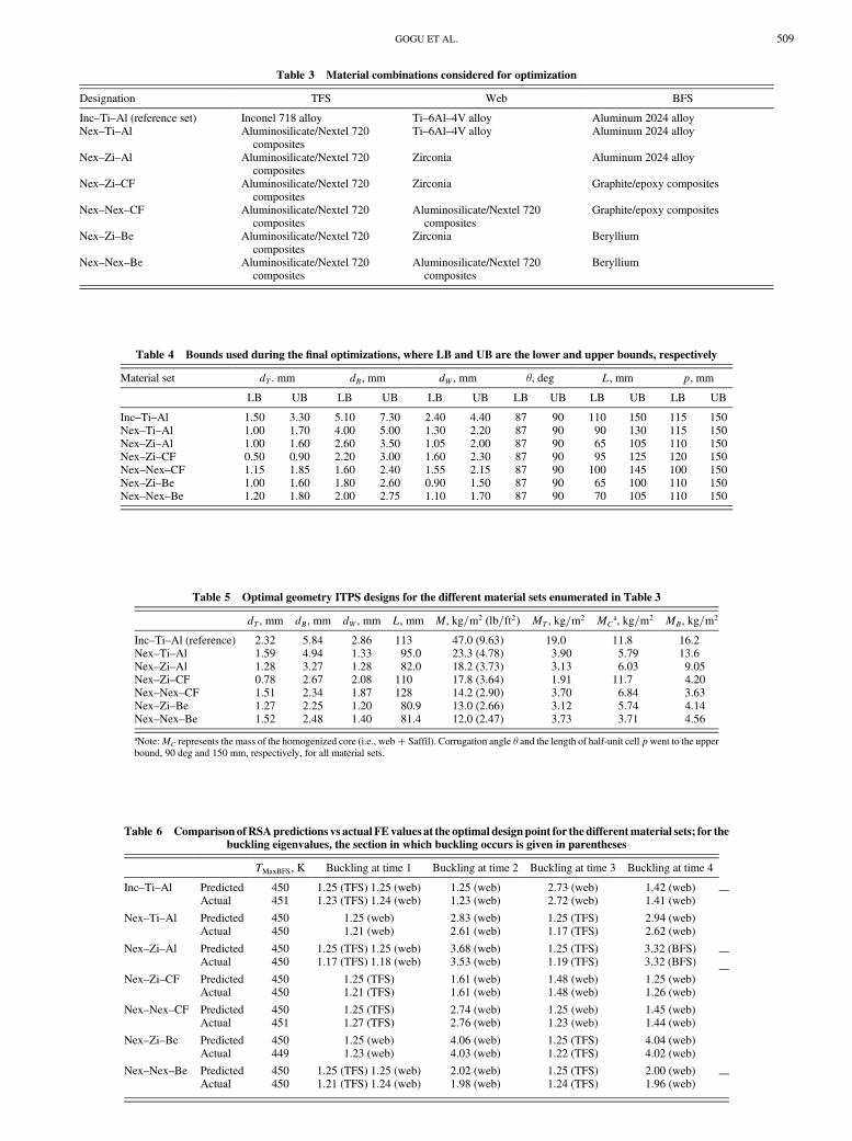
Table 3 Material combinations considered for optimization
Designation TFS Web BFS
Inc–Ti–Al (reference set) Inconel 718 alloy Ti–6Al–4V alloy Aluminum 2024 alloyNex–Ti–Al Aluminosilicate/Nextel 720
compositesTi–6Al–4V alloy Aluminum 2024 alloy
Nex–Zi–Al Aluminosilicate/Nextel 720composites
Zirconia Aluminum 2024 alloy
Nex–Zi–CF Aluminosilicate/Nextel 720composites
Zirconia Graphite/epoxy composites
Nex–Nex–CF Aluminosilicate/Nextel 720composites
Aluminosilicate/Nextel 720composites
Graphite/epoxy composites
Nex–Zi–Be Aluminosilicate/Nextel 720composites
Zirconia Beryllium
Nex–Nex–Be Aluminosilicate/Nextel 720composites
Aluminosilicate/Nextel 720composites
Beryllium
Table 4 Bounds used during the final optimizations, where LB and UB are the lower and upper bounds, respectively
Material set dT . mm dB, mm dW , mm �, deg L, mm p, mm
LB UB LB UB LB UB LB UB LB UB LB UB
Inc–Ti–Al 1.50 3.30 5.10 7.30 2.40 4.40 87 90 110 150 115 150Nex–Ti–Al 1.00 1.70 4.00 5.00 1.30 2.20 87 90 90 130 115 150Nex–Zi–Al 1.00 1.60 2.60 3.50 1.05 2.00 87 90 65 105 110 150Nex–Zi–CF 0.50 0.90 2.20 3.00 1.60 2.30 87 90 95 125 120 150Nex–Nex–CF 1.15 1.85 1.60 2.40 1.55 2.15 87 90 100 145 100 150Nex–Zi–Be 1.00 1.60 1.80 2.60 0.90 1.50 87 90 65 100 110 150Nex–Nex–Be 1.20 1.80 2.00 2.75 1.10 1.70 87 90 70 105 110 150
Table 5 Optimal geometry ITPS designs for the different material sets enumerated in Table 3
dT , mm dB, mm dW , mm L, mm M, kg=m2 �lb=ft2� MT , kg=m2 MC
a, kg=m2 MB, kg=m2
Inc–Ti–Al (reference) 2.32 5.84 2.86 113 47.0 (9.63) 19.0 11.8 16.2Nex–Ti–Al 1.59 4.94 1.33 95.0 23.3 (4.78) 3.90 5.79 13.6Nex–Zi–Al 1.28 3.27 1.28 82.0 18.2 (3.73) 3.13 6.03 9.05Nex–Zi–CF 0.78 2.67 2.08 110 17.8 (3.64) 1.91 11.7 4.20Nex–Nex–CF 1.51 2.34 1.87 128 14.2 (2.90) 3.70 6.84 3.63Nex–Zi–Be 1.27 2.25 1.20 80.9 13.0 (2.66) 3.12 5.74 4.14Nex–Nex–Be 1.52 2.48 1.40 81.4 12.0 (2.47) 3.73 3.71 4.56
aNote:MC represents the mass of the homogenized core (i.e., web� Saffil). Corrugation angle � and the length of half-unit cell pwent to the upperbound, 90 deg and 150 mm, respectively, for all material sets.
Table 6 Comparison ofRSApredictions vs actual FEvalues at the optimal designpoint for the differentmaterial sets; for thebuckling eigenvalues, the section in which buckling occurs is given in parentheses
TMaxBFS, K Buckling at time 1 Buckling at time 2 Buckling at time 3 Buckling at time 4
Inc–Ti–Al Predicted 450 1.25 (TFS) 1.25 (web) 1.25 (web) 2.73 (web) 1.42 (web)Actual 451 1.23 (TFS) 1.24 (web) 1.23 (web) 2.72 (web) 1.41 (web)
Nex–Ti–Al Predicted 450 1.25 (web) 2.83 (web) 1.25 (TFS) 2.94 (web)Actual 450 1.21 (web) 2.61 (web) 1.17 (TFS) 2.62 (web)
Nex–Zi–Al Predicted 450 1.25 (TFS) 1.25 (web) 3.68 (web) 1.25 (TFS) 3.32 (BFS)Actual 450 1.17 (TFS) 1.18 (web) 3.53 (web) 1.19 (TFS) 3.32 (BFS)
Nex–Zi–CF Predicted 450 1.25 (TFS) 1.61 (web) 1.48 (web) 1.25 (web)Actual 450 1.21 (TFS) 1.61 (web) 1.48 (web) 1.26 (web)
Nex–Nex–CF Predicted 450 1.25 (TFS) 2.74 (web) 1.25 (web) 1.45 (web)Actual 451 1.27 (TFS) 2.76 (web) 1.23 (web) 1.44 (web)
Nex–Zi–Be Predicted 450 1.25 (web) 4.06 (web) 1.25 (TFS) 4.04 (web)Actual 449 1.23 (web) 4.03 (web) 1.22 (TFS) 4.02 (web)
Nex–Nex–Be Predicted 450 1.25 (TFS) 1.25 (web) 2.02 (web) 1.25 (TFS) 2.00 (web)Actual 450 1.21 (TFS) 1.24 (web) 1.98 (web) 1.24 (TFS) 1.96 (web)
GOGU ET AL. 509

The Nextel 720 composites (TFS and web), beryllium (BFS) ITPSwas found to withstand in-plane loads of 3:0 105 N=m (a typicalload for X-33 RLV-type vehicles) with a safety factor of 2.47 for thecritical buckling failure. Note that the mass comparison figureobtained (44%mass increase) is application specific. It was obtainedfor the corrugated core ITPS design and thermal reentry conditionsdescribed in Sec. II.A. Although it can not be generalized, it is,however, an indicator of potential mass savings achievable with anintegrated design.
Beryllium, which is used in the BFS of the lightest ITPS designwefound, could pose issues during manufacturing, in particular relativeto beryllium’s toxicity. If we want to use a less exotic material forthe BFS, we can note that the design with Nextel 720 composites(for TFS and web) and graphite/epoxy composites for BFS leads to amass of 14:2 kg=m2 (2:9 lb=ft2), which is about 18% heavier thanthe beryllium BFS design.
We note at this point that no manufacturing constraints have beenconsidered in this study. Manufacturing would probably be a majordesign problem by itself, but would probably be very specific to thematerials chosen. If one of the designs determined here is found to beappealing enough, additional studies would then be necessary toinvestigate the best way of manufacturing and how to avoid otherissues such as stress concentrations and the attachment of thesections to each other and to the vehicle.
V. Conclusions
A material selection study for an ITPS was presented that soughtmaterial combinations togetherwith the corresponding optimal panelgeometry for low-mass designs. For this purpose, a two-step ap-proach was used.
In the first step, good potential materials were selected mainlyfrom a thermal perspective. For this purpose, an approximation ofthe maximum BFS temperature of the ITPS panel was constructedusing several simplifying assumptions, a dimensional analysis, and aglobal sensitivity analysis for reducing the number of variablesrelevant for the maximum BFS temperature from 15 to 2. It wasfound that this approximation in terms of the two nondimensionalvariables is relatively accurate (for our use and, over a range of 250K,the error was less than 7.6K comparedwith analyses not using any ofthe simplifying assumptions). The two-dimensional approximationwas used in combination with a search in a materials database to findthe most promising materials. Then, in the second step, a coupledthermomechanical optimization of the geometry of the ITPS, using
both thermal and structural constraints, allowed us to rank thedifferent material combinations with respect to mass.
We found that the materials selection process is a critical step inthe ITPS design because the mass is very sensitive to the materialsused, the lightest design being over 3 times lighter than the originalreference design. The ranking of the different material combinationsexamined also showed that aluminosilicate/Nextel 720 composites(for TFS and web) and beryllium (for BFS) leads to the lightestITPS design with a mass per unit area of 12:0 kg=m2 (2:47 lb=ft2).We found that, for identical thermal conditions, the ITPS basedon this material combination is only about 40% heavier than areference TPS-only design, sized at the same preliminary designphase as the ITPS and that considered the same corrugated corepanel concept but without imposing any structural requirements(zero web thickness). However, whereas the TPS-only design pro-vides only thermal protection, the ITPS concept was shown to beable to provide significant structural load bearing capabilities aswell.
Appendix A: Variable Reduction for Thermal Analysis
To reduce computational cost and improve user-friendliness, wesought to reduce to a minimum the number of variables neededto express the maximum BFS temperature, if possible to only twovariables. For this purpose, we used a combination of simplifyingassumptions, dimensional analysis, and global sensitivity analysis,which led to amildly simplified problem allowing us to condense therelevant material parameters into a small number of nondimensionalparameters. To facilitate nondimensionalization, wemade followingsimplifying assumptions:
1) The three thermal properties of the TFS (CT , kT , and �T) have anegligible impact on the maximum BFS temperature, mainly due tothe small thickness of the TFS (about 2.2 mm compared with a totalITPS thickness of about 120 mm). Consequently CT , kT , and �Twere removed from the relevant parameters influencing the BFStemperature.
2) The temperature is approximately constant through the BFS,because the BFS thickness is small (typically 5 mm thick comparedwith a total ITPS thickness of 120 mm) and its conductivity is about1 order of magnitude higher than that of the homogenized core. Thisallows removing kB from the relevant parameters and simplifying theboundary condition at the BFS.
3) The material properties were treated as constant (temperatureindependent). In the exact FE model (described in Sec. II.A), tem-perature dependence has been included for all materials, butthe largest dependence was that of the Saffil® foam. Thus, in thesimplified problem TFS, web, and BFS materials were assignedconstant properties based on their nominal values given in the CESSelector 2005 material database [14]. The properties of the databasematerials used are also restated in Appendix B. For Saffil®, thematerial properties were assigned the values at a representativetemperature chosen to minimize the difference between the maxi-mum BFS temperature when using the constant values and the onewhen using temperature-dependent values for an ITPS design withthe dimensions given in Table 2 and a Nextel (TFS), zirconia (web),aluminum (BFS) material combination. Because the representativetemperature was determined for this fixed material combination, wetested the effects of varying the materials and found them to be smallenough to use this representative temperature for the entire range ofmaterials we consider.
Under these assumptions, the thermal problem is simplified asshown in Fig. A1 and its equations can be rewritten as follows.
Heat conduction equation:
kC@2T�x; t�@x2
� �CCC@T�x; t�@t
for 0< t < tend
Initial condition:
T�x; t� 0� � Ti
0
5
10
15
20
25
30
35
40
45
50
Inc-Ti-Al (reference)
Nex-Ti-Al
Nex-Zi-Al
Nex-Zi-CF
Nex-Nex-CF
Nex-Zi-Be
Nex-Nex-Be
M (
kg/m
2)
M TFS
M Core
M BFS
Fig. 11 Graphical representation of the mass distribution for theoptimal geometry designs of different material sets.
510 GOGU ET AL.

Boundary conditions:
qout ��kC@T�x; t�@x
����x�dC��BCBdB
@T�x; t�@t
����x�dC
qin ��kC@T�x; t�@x
����x�0�qi�t� � "�T�0; t�4 � h�t�T�0; t�
To nondimensionalize the equations of this problem, we used theVaschy–Buckingham theorem (or Pi theorem) [16,17] and thefollowing nondimensional variables were defined:
T
Ti� �
x
dC� � t
tend� � kCtend
d2C�CCC� �
dB�BCBdC�CCC
� � dC"�T3i
kC� � dCqi�t�
kCTi� ’���
h�t�dCkC� Bi���
In terms of these nondimensional variables, the thermal problem canbe written in the following nondimensional form:
Heat conduction equation:
�@2�
@�2� @�@�
for 0< � < 1
Initial condition:
���; � � 0� � 1
Boundary conditions:
� �@�@�
������1�� @�
@�
������1
and
� @�@�
������0�’��� � � � ��0; ��4 � Bi��� � ��0; ��
The nondimensional temperature � can be expressed as a functionof the nondimensional distance �, the nondimensional time �, andfive other nondimensional parameters. At the maximum BFS tem-perature, we are at a fixed location (because we ignore the BFSthickness) and are not interested in the time at which this maximumoccurs. Accordingly, the maximum BFS temperature is independentof the nondimensional distance � and the nondimensional time �.
The physical interpretation of the remaining five nondimensionalparameters is the following. The Fourier number � is a non-dimensional thermal diffusivity, that is, the ratio between the rate ofheat conduction and the rate of heat storage (thermal energy storage)
of the homogenized core; � is the ratio between the heat capacity ofthe BFS and heat capacity of the homogenized core; � is the ratiobetween the rate of radiation and the rate of heat conduction; and ’ isthe ratio between the incident heat flux and the rate of heatconduction, or it can be seen as a nondimensional heat flux. FinallyBi, the Biot number, is the ratio between the rate of convection andthe rate of heat conduction.
The three nondimensional parameters �, ’, and Bi are all pro-portional to dC=k, whereas all the other parameters in �, ’, andBi arefixed in our study. Indeed, we are only interested in varying thematerials and the geometry; the initial temperature Ti, the emissivity", the incident heat flux profile qi�t�, and the convection filmcoefficient profile h�t� are all fixed in the present study (see Fig. 3for the profiles of qi�t� and h�t� used). This means that for ourpurpose we can consider only one of these three nondimensionalparameters, and we chose �. Summing up, for the purpose of thematerial selection, the maximum BFS temperature can be expressedas a function of only three parameters: �, � and �.
From initial FE analyses, it seemed that the maximum BFS tem-perature was relatively insensitive to �. To check this, we used 343FE simulations (a 7 7 7 grid in �, �, and �) and conducted aglobal sensitivity analysis using Sobol’s approach [18]. We foundthat � accounts for 35.76% of the model variance and � accounts for64.18%, whereas � accounts for only 0.06%. Thus, we can explainalmost the entire behavior of the model with only the two variables� and �.
From a physical point of view, the fact that � has a negligible rolecan be explained as follows: � is proportional to dC=k, which is alsopresent in�. That means that, if wewant to change �while keeping�constant, we need to alsomodify tend (which is the only other variablein � that does not appear either in � or in �). If we increase � bydecreasing kC, we need to also increase tend by a certain amount tokeep � constant. Decreasing kC has the effect of lowering the BFStemperature, whereas increasing tend has the effect of making ithigher. From the global sensitivity analysis, it turns out that these twoeffects cancel each other out, which explains why � has very littleimpact.
To find the limits of the simplifying assumptions that wereconsidered to achieve this reduction in the number of variables, anantioptimization procedure was carried out, the details of which areprovided in [19]. The antioptimization process looks to find theplaces with the highest error in using an approximation in termsof the reduced number of variables. By looking at the designscorresponding to the antioptimum, we can understand what causesthese errors. This procedure showed that the approximation in termsof the reduced number of variables has poor accuracy when thegeometry is far away from the one for which the representativetemperature of the core was established (see assumption 3 at thebeginning of this Appendix). For these unusual geometries, therepresentative temperature shifts due to temperature dependence ofthe core. This temperature shift is poorly accounted for by theapproximation, which explains the poor accuracy for these geo-metries. To further improve the accuracy of the temperature approxi-mation for a large range of geometries, we would have to addnondimensional parameters that account for the temperature depen-dence. For the geometries for which we used the approximation interms of the reduced number of variables in this paper, it was foundthat the errors are acceptable (a maximum error of less than about10 K). Additional details on testing and validation are also providedin Sec. II.B.
Appendix B: Properties of Candidate Materials
The material properties of the candidate materials for the web,BFS, and TFS are provided in Tables B1–B3, respectively. Thematerial properties come from the CES Selector 2005 materialdatabase [14]. The ranges of the material properties are due touncertainty in identifying them or to variations due to differentpossible manufacturing processes.
Homogenized core material
ρC, CC, kC
0
dC
xqout to BFS
qi qrad + qconv
Fig. A1 Simplified thermal problem for dimensional analysis.
GOGU ET AL. 511

Table B2 Selected BFS materials properties
Designation Cast aluminum alloy Epoxy/carbon fiber quasi-isotrop.laminate
Beryllium, grade S-200F,vacuum hot pressed
Mechanical propertiesDensity kg=m3 2570–2950 1550–1580 1840–1860Young’s modulus GPa 68–88.5 49.7–60.1 290–315Compressivestrength
MPa 30–280 542.1–656.8 250–365
Tensile strength MPa 75–360 248.6–355.9 320–430Fracture toughness MPa �m0:5 18–35 6.12–87.61 10–14Poisson’s ratio 0.32–0.36 0.305–0.307 0.06–0.075Shear modulus GPa 25–34 19–23.01 134–150Thermal propertiesMax. service temp. K 403–473 413–493 803–1103Melting point K 723–980 373–453 1545–1565Specific heat J=kg � K 944–982 901.7–1037 1820–1930Thermalconductivity
W=m � K 80–220 1.28–2.6 190–216
Thermal expansion strain=K 16–24 0.36–4.02 10–12Price (2005 USD) USD=kg 1.42–2.3 58.48–72.05 735.2–867.1
Table B3 Selected TFS materials properties (note that carbon–carbon composites were not selected for the geometry optimization study of
Sec. IV due to their low fracture toughness; their properties are nevertheless listed for information purposes)
Designation Nickel–chromium alloy, Inconel 718 Aluminosilicate/Nextel 720 fibercomposite, quasi-isotropic woven
Carbon fibercarbon matrixcomposite
Mechanical propertiesDensity kg=m3 8150–8300 2450–2600 1440–1720Young’s modulus GPa 195–205 133.5–139.1 8.3–100Compressivestrength
MPa 1010–1240 67.9–68.8 17–247
Tensile strength MPa 1220–1510 67.9–68.8 6.9–34.5Fracture toughness MPa �m0:5 120–150 40.5–47.6 5.7–6.3Poisson’s ratio 0.28–0.3 0.23–0.25 0.31–0.35Shear modulus GPa 73–81 54.15–55.64 3.2–34Thermal propertiesMax. service temp. K 1130–1255 1273–1373 2275–2325Melting point K 1533–1610 1273–1373 3473–3673Specific heat J=kg � K 410–455 950–1100 754–1700Thermalconductivity
W=m � K 10.5–12.5 2.52–2.93 10–87
Thermal expansion strain=K 11.5–13.5 5.745–5.745 0.2–8.4Price (2005 USD) USD=kg 13.2–26.39 4807–5750 188.5–207.4
Table B1 Selected web materials properties
Designation Titanium alpha-beta alloyTi–6Al–4V (STA)
Zirconia (HTZ) Aluminosilicate/Nextel 720fiber composite, quasi-
isotropic woven
Mechanical propertiesDensity kg=m3 4407–4451 6080–6210 2450–2600Young’s modulus GPa 110–117 209.7–220.4 133.5–139.1Compressivestrength
MPa 758–1117 1429–1575 67.9–68.8
Tensile strength MPa 896–1138 142.9–157.5 67.9–68.8Fracture toughness MPa �m0:5 82–100 15–20 40.5–47.6Poisson’s ratio 0.31–0.32 0.24–0.31 0.23–0.25Shear modulus GPa 43–45.21 82.25–86.4 54.15–55.64Thermal propertiesMax. service temp. K 630–672 1248–1298 1273–1373Melting point K 1878–1933 2823–2973 1273–1373Specific heat J=kg � K 553–575.6 418–436 950–1100Thermalconductivity
W=m � K 7.3–7.9 1.8–1.9 2.52–2.93
Thermal expansion strain=K 9–9.46 7.8–8.1 5.745–5.745Price (2005 USD) USD=kg 28.28–47.13 16.97–24.51 4807–5750
512 GOGU ET AL.

Acknowledgments
The authorswould like to thankMaxBlosser fromNASALangleyResearch Center for his valuable input during the teleconferences wehad. They also thank Tushar Goel for his assistance with the globalsensitivity analysis. Finally, they gratefully acknowledge financialsupport from the NASA Constellation University Institutes Project(formerly University Research Engineering and Technology Insti-tutes) grant NCC3-994 to the Institute for Future Space Transport atthe University of Florida. The cognizant program managers areClaudia Meyer and Jeffry Rybak at the NASA John H. GlennResearch Center at Lewis Field.
References
[1] Erb, R. B., Greenshields, D. H., Chauvin, L. T., Pavlosky, J. E., andStatham, C. L., “Apollo Thermal-Protection System Development,”Journal of Spacecraft and Rockets, Vol. 7, No. 6, June 1970, pp. 727–734.doi:10.2514/3.30027
[2] Olynick, D., Chen, Y. K., and Tauber, M. E., “Forebody TPS Sizingwith Radiation and Ablation for the Stardust Sample Return Capsule,”AIAA Paper 1997-2474, June 1997.
[3] Cooper, P. A., and Holloway, P. F., “The Shuttle Tile Story,”Astronautics and Aeronautics, Vol. 19, No. 1, Jan. 1981, pp. 24–34.
[4] Freeman, D. C., Talay, T. A., and Austin, R. E., “Reusable LaunchVehicle Technology Program,” Acta Astronautica, Vol. 41, No. 11,1997, pp. 777–790.doi:10.1016/S0094-5765(97)00197-5
[5] Baumgartner, R. I., “VenturestarTM Single Stage to Orbit ReusableLaunch Vehicle Program Overview,” AIP Conference Proceedings
Space Technology and Applications International Forum, Vol. 387,American Institute of Physics, College Park, MD, Jan. 1997, pp. 1033–1040.
[6] Blosser, M. L., Chen, R. R., Schmidt, I. H., Dorsey, J. T., Poteet, C. C.,Bird, R. K., and Wurster, K. E., “Development of Advanced Metallic,Thermal-Protection-System Prototype Hardware,” Journal of Space-
craft and Rockets, Vol. 41, No. 2, March–April 2004, pp. 183–194.doi:10.2514/1.9179
[7] Poteet, C. C., Abu-Khajeel, H., and Hsu, S.-Y., “Preliminary Thermal-Mechanical Sizing of a Metallic Thermal Protection System,” Journal
of Spacecraft andRockets, Vol. 41,No. 2,Mar–Apr 2004, pp. 173–182.doi:10.2514/1.9174
[8] Kim, W. Y., Grandhi, R. V., and Haney, M., “Multi-ObjectiveEvolutionary Structural OptimizationUsingCombined Static/DynamicControl Parameters,” AIAA Journal, Vol. 44, No. 4, April 2006,pp. 794–802.doi:10.2514/1.16971
[9] Bapanapalli, S. K., Martinez, O. M., Gogu, C., Sankar, B. V.,Haftka, R. T., and Blosser, M. L., “Analysis and Design ofCorrugated Core Sandwich Panels for Thermal Protection Systemsof Space Vehicles,” AIAA Paper 2006-1942, 2006.
[10] Martinez, O., Bapanapalli, S. K., Sankar, B. V., Haftka, R. T., andBlosser, M. L., “Micromechanical Analysis of Composite Truss-CoreSandwich Panels for Integral Thermal Protection Systems,” AIAAPaper 2006-1876, 2006.
[11] ABAQUS/Standard User’s Manual, Ver. 6.5.1, Hibbitt, Karlsson, andSorensen, Inc., Pawtucket, RI, 2004.
[12] Williams, S. D., and Curry, D. M., “Thermal Protection Materials,”NASA RP-1289, 1992.
[13] Myers, D. E., Martin, C. J., and Blosser, M. L., “Parametric WeightComparison of AdvancedMetallic, Ceramic Tile, and Ceramic BlanketThermal Protection Systems (TPS),” NASA TM-2000-210289, 2000.
[14] CES Selector Edupack 2005, Granta Design Limited, Cambridge,England, UK, 2005.
[15] Anon., “Columbia Accident Investigation Board Report,” NASA,Washington, DC, 2003.
[16] Vaschy, A., “Sur les Lois de Similitude en Physique,” Annales
Télégraphiques, Vol. 19, 1892, pp. 25–28.[17] Buckingham, E., “On Physically Similar Systems; Illustration of the
Use of Dimensional Equations,” Physical Review, Vol. 4, 1914,pp. 345–376.doi:10.1103/PhysRev.4.345
[18] Sobol, I. M., “Sensitivity Estimates for Nonlinear MathematicalModels,” Mathematical Modeling and Computational Experiment,Vol. 1, Wiley, New York, 1993, pp. 407–414.
[19] Gogu, C., Bapanapalli, S. K., Haftka, R. T., and Sankar, B. V.,“Comparison of Materials for Integrated Thermal Protection Systemsfor Spacecraft Reentry,” AIAA Paper 2007-1860, April 2007.
K. WursterAssociate Editor
GOGU ET AL. 513