comparison of experimental values with ec 4, aci-318, aisc
TRANSCRIPT

American Journal of Engineering Research (AJER) 2014
w w w . a j e r . o r g
Page 335
American Journal of Engineering Research (AJER)
e-ISSN : 2320-0847 p-ISSN : 2320-0936
Volume-03, Issue-05, pp-335-344
www.ajer.org
Research Paper Open Access
Comparison of Experimental values with EC 4, ACI-318, AISC-
LRFD of Concrete Filled Steel Fluted Columns for Concentric
Load
Dr.B.R Niranjan1
&
Eramma.H2
1Professor, 2Research Scholar , UVCE, Faculty of Engineering-Civil, Jnana Bharati Campus, Bangalore
University, Bangalore: 560056, karnataka INDIA
Abstract: - The advantages of Concrete Filled Steel Tube (CFST) columns have proved its usefulness in the structural applications of the constructions. Though, application of CFST columns are gaining popularity, the
analysis and design of these have not found a place in the codes of Bureau of Indian Standard Specifications.
But, this has been incorporated in the codes of ACI 318. AISC - LRFD and EC 4 - Euro codal provisions. An attempt has been made here to check whether these equations can be made use for the analysis and design of
Concrete Filled Steel Fluted Columns (CFSFC) also. It has been observed that by adopting EC 4, (Eurocode 4),
for a Triangular Fluted Column (TFC), a discrepancy of about 47 percent has been observed. Whereas , ACI 318
and AISC -LRFD has shown about 48% and 64% respectively less compared to the experimental values. Similar
results have been observed for Rectangular Fluted Columns (RFC).
Keywords: - CFST, CFSFC, TFC, RFC, SCC
I. INTRODUCTION Technology of concrete filled steel tubular column was evolved as early as 1970’s, itself, and there has
been enough research carried out to understand the complete behaviour of these columns. CFST is a composite
structural member, which resists the applied loads through the composite action of steel as well as concrete. The
interactive and integral behaviour of concrete and structural steel elements makes it a cost effective alternative.
In addition to its improved load carrying capacity, it is also aesthetically pleasing. With recent developments in
the CFST columns beam column connections and advantage of fire resistant construction, architects have seized the opportunity to exploit the structural and aesthetic advantages of these columns in multistoried buildings.
Since the steel confines concrete, the use of formwork can be discarded and the buckling strength increases .
Due to the presence of concrete core, local buckling of steel tube is delayed and the strength deterioration after
local buckling is moderated, both due to restraining effect of concrete. The strength of concrete is increased, due
to the confining effect provided by steel tube and on other hand the strength deterioration is not that severe
because concrete does not spall due to the confinement. Drying shrinkage and creep of concrete are much
smaller in these columns as compared to other structural forms. Having listed all the advantages, however the
major disadvantage of a composite column is the exposure of tube to the environmental effects (such as heat,
cold, UV etc). For steel tubes, this raises concerns related to susceptibility to corrosion and fire safety. The
structural properties of CFST columns include high strength, high ductility and high energy absorption capacity.
The load carrying capacity and behaviour in compression, bending and shear are all superior to reinforced concrete. The reduction of the steel tube thickness in thin-walled CFST columns has the potential to
significantly reduce construction costs. However, thin-wall CFST columns are susceptible to the local instability
problem of thin-walled steel plates under compression and in-plane bending. The local buckling of steel tubes
with geometric imperfections and residual stresses results in a reduction in the strength and ductility of
members. Extensive research have been made for the past forty years in the field of concrete-filled steel tubular
(CFST) columns, which are used as primary axial load carrying members in many structural applications
including high rise buildings, bridges, piles and off shore structures. Researchers have carried out on plain CFST
compression members, but no research has been carried out on fluted columns. The load carrying capacity and

American Journal of Engineering Research (AJER) 2014
w w w . a j e r . o r g
Page 336
behaviour in compression, bending and shear are all superior to reinforced concrete. Currently there is no
comprehensive design standard that can be used for the design of thin-walled CFST columns. Extensive
research have been conducted on steel-concrete composite columns in which structural steel encases concrete.
The CFST fluted column is a structural member which resists the applied loads through the composite
action of steel and concrete. However, the effect of confinement is required to be studied. Here a new approach
of confining concrete by providing triangular and rectangular shaped fluting is being investigated by a well
planned experimental work on concrete filled steel fluted columns. The parameter adopted for the study were
(i) different shapes of fluted steel tubes. (ii) Different L/D ratio (iii) Without reinforcement and varying the
number of reinforcements from 3 to 6 (iv) To obtain an appropriate method for the analysis and design of CFSFC among various codes. Results have been analyzed for M20 Self Compacting Concrete (SCC) specimens
with respect to buckling characteristics, load deformations, stress strain characteristics and stiffness.
1.2 Experimental Setup:
The tests were conducted using a 2000 kN capacity hydraulic jack placing the specimen in the testing
machine and geometry of the specimens are as shown in Fig. 1 to 3. The bearing surfaces of the testing machine
and the bearing plates were wiped clean and any loose sand or other material removed from the surface of the
specimen. Which were to be in contact with the bearing plates. The specimen was placed between the bearing
plates in such a manner that the upper bearing plates was directly in line with the lower plate and the bearing
plates extend at least 25 mm from each end of the specimen. The columns were placed on smooth plates at both
ends. Care was taken to ensure that truly axial load was applied to each of the columns. Plumb bob and Theodolite has been employed to place the specimen truly vertical and hence load the specimen concentrically
as shown in Fig. 4.
No Reinforcement 3#8 4#8 5#8 6#8
Fig1. Triangular Fluted Steel Tube With and Without Reinforcement
No Reinforcement 3#8 4#8 5#8 6#8
Fig 2. Rectangular Fluted Steel Tube With and Without Reinforcement

American Journal of Engineering Research (AJER) 2014
w w w . a j e r . o r g
Page 337
Fig.3.Experimental Setup Fig. 4. Overall Experimental Setup with Theodolite
1.3 Experimental Programme
Thirteen concrete filled triangular fluted column test specimens with L/D= 15, 20, 25 and thirteen
concrete filled rectangular fluted column test specimens with L/D = 15, 20, 25 were tested under concentric
axial compression. All the columns were circular in shape provided with five triangular shaped and rectangular
shaped fluting running the length of the column. The steel fluted core was obtained by pressing a plane mild
steel sheet at 5 different locations in triangular shape and rectangular shape. The resulting section was then
closed by using tack and arc welding, which was continuous throughout the length of the column. All the
specimen were 2500 mm tall and 0.8 mm thick In all columns were designed by using self compacting concrete
M 20 grade of concrete. Test was conducted in a loading frame of capacity 100 tones, using a hydraulic jack of
capacity 2000 kN with an accuracy of 10 kN. Initial seating of load of 50 kN was applied and all the temporary supports were removed. The alignment of the column was Faculty of Engineering-Civil verified at the same
time. At the outset , the increase in axial deformation with the increase in load was found to be marginal. The
columns were placed restraining rotation at both ends and the loads were applied without shock at an increment
of 50 kN until the resistance of the specimen to the increasing load breaks down and no greater load can be
sustained. Special attention was given to verifying the correct position of the column, before any loading. After
completing the initial set up the specimen were placed on the loading jacked to fix the specimen between two
supports. Care was taken to maintain vertically along both vertical plane and line of action of load and loading
axis . The maximum load and load applied to the specimen was then recorded and the appearance of the
concrete and any unusual features in the type of failure noted. For details refer Tables 1 & 2.
American Journal of Engineering Research (AJER) 2014
w w w . a j e r . o r g
Page 338
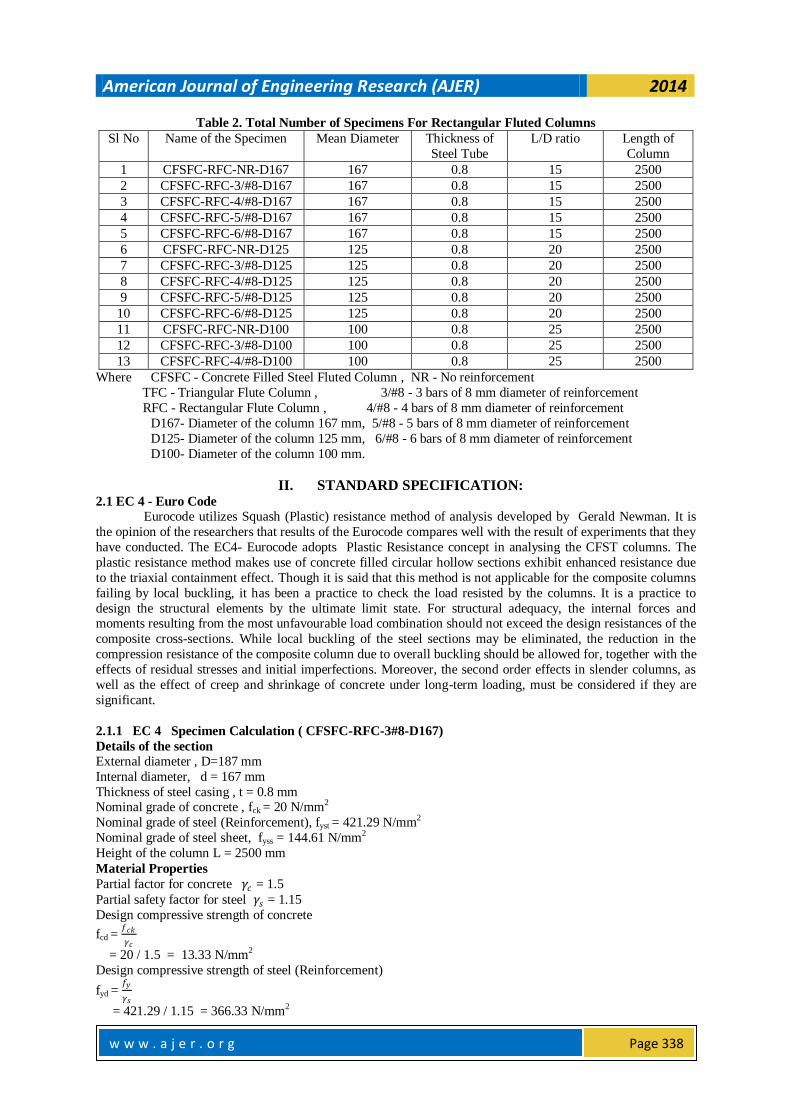
Table 2. Total Number of Specimens For Rectangular Fluted Columns
Sl No Name of the Specimen Mean Diameter Thickness of
Steel Tube
L/D ratio Length of
Column
1 CFSFC-RFC-NR-D167 167 0.8 15 2500
2 CFSFC-RFC-3/#8-D167 167 0.8 15 2500
3 CFSFC-RFC-4/#8-D167 167 0.8 15 2500
4 CFSFC-RFC-5/#8-D167 167 0.8 15 2500
5 CFSFC-RFC-6/#8-D167 167 0.8 15 2500
6 CFSFC-RFC-NR-D125 125 0.8 20 2500
7 CFSFC-RFC-3/#8-D125 125 0.8 20 2500
8 CFSFC-RFC-4/#8-D125 125 0.8 20 2500
9 CFSFC-RFC-5/#8-D125 125 0.8 20 2500
10 CFSFC-RFC-6/#8-D125 125 0.8 20 2500
11 CFSFC-RFC-NR-D100 100 0.8 25 2500
12 CFSFC-RFC-3/#8-D100 100 0.8 25 2500
13 CFSFC-RFC-4/#8-D100 100 0.8 25 2500
Where CFSFC - Concrete Filled Steel Fluted Column , NR - No reinforcement
TFC - Triangular Flute Column , 3/#8 - 3 bars of 8 mm diameter of reinforcement
RFC - Rectangular Flute Column , 4/#8 - 4 bars of 8 mm diameter of reinforcement
D167- Diameter of the column 167 mm, 5/#8 - 5 bars of 8 mm diameter of reinforcement
D125- Diameter of the column 125 mm, 6/#8 - 6 bars of 8 mm diameter of reinforcement
D100- Diameter of the column 100 mm.
II. STANDARD SPECIFICATION: 2.1 EC 4 - Euro Code
Eurocode utilizes Squash (Plastic) resistance method of analysis developed by Gerald Newman. It is
the opinion of the researchers that results of the Eurocode compares well with the result of experiments that they
have conducted. The EC4- Eurocode adopts Plastic Resistance concept in analysing the CFST columns. The
plastic resistance method makes use of concrete filled circular hollow sections exhibit enhanced resistance due
to the triaxial containment effect. Though it is said that this method is not applicable for the composite columns
failing by local buckling, it has been a practice to check the load resisted by the columns. It is a practice to
design the structural elements by the ultimate limit state. For structural adequacy, the internal forces and moments resulting from the most unfavourable load combination should not exceed the design resistances of the
composite cross-sections. While local buckling of the steel sections may be eliminated, the reduction in the
compression resistance of the composite column due to overall buckling should be allowed for, together with the
effects of residual stresses and initial imperfections. Moreover, the second order effects in slender columns, as
well as the effect of creep and shrinkage of concrete under long-term loading, must be considered if they are
significant.
2.1.1 EC 4 Specimen Calculation ( CFSFC-RFC-3#8-D167)
Details of the section
External diameter , D=187 mm
Internal diameter, d = 167 mm
Thickness of steel casing , t = 0.8 mm Nominal grade of concrete , fck = 20 N/mm2
Nominal grade of steel (Reinforcement), fyst = 421.29 N/mm2
Nominal grade of steel sheet, fyss = 144.61 N/mm2
Height of the column L = 2500 mm
Material Properties
Partial factor for concrete 𝛾𝑐 = 1.5
Partial safety factor for steel 𝛾𝑠 = 1.15
Design compressive strength of concrete
fcd = 𝑓𝑐𝑘
𝛾𝑐
= 20 / 1.5 = 13.33 N/mm2
Design compressive strength of steel (Reinforcement)
fyd = 𝑓𝑦
𝛾𝑠
= 421.29 / 1.15 = 366.33 N/mm2

American Journal of Engineering Research (AJER) 2014
w w w . a j e r . o r g
Page 339
Design compressive strength of steel (Reinforcement)
fsdss = 𝑓𝑦
𝛾𝑠
= 144.61 / 1.15 = 125.74 N/mm2
Section Properties
Area of concrete
Ac = { 𝜋 𝑑 2
4 + 5 ( l x h)}
= [( π x (167)2 )/4] + 5 ( 40 x 10)
= 23903.96 mm2
Area of steel sheet
Ass = A2 = {(2πr – 5xl) + 10xh+(5xL)}x t
= {(2xπ x 83.5 – 5x 40 ) + (10x 10)+(5x40)}x 0.8
= 499.71 mm2
Area of steel (reinforcement)
Ast = As = 𝜋 𝑑 2
4 x n
= π (8)2 / 4 x 3
= 150.79 mm2
Moment of Inertia of concrete Ic = 46 x 106 mm4
Moment of Inertia of steel sheet
Iss = 0.01445 x 106 mm4
Moment of Inertia of reinforcement
Ic = 0.024439203 = 24.43 x 10⁻³ mm4
Elastic Flexural Stiffness
Modulus of Elasticity of Steel
Ess = 0.72 x 10⁵ N/mm2
Est = 2.1 x 10⁵ N/mm2
Safety factor for stiffness 𝛾𝑐𝑒 = 1.35 Correction factor ke = 0.8
Ecm = 9500( fck + 0.8 )1/3
= 9500 ( 20 + 0.8)1/3
= 26126.30 N/mm2 = 26127 N/mm2
Ratio of Secant modulus to safety factor
Ecd = 𝐸𝑐𝑚
𝛾𝑐𝑒
= 26127/1.35
= 19352.82 N/mm2 ≈ 19353 N/mm2
The plastic resistance of a concrete filled circular hollow section may be obtained as follows
Npl,Rd = A2 ɳ2fyd + As fsd + Ac fcd 1 + ɳ
1 𝑡
𝑑
𝑓𝑦
𝑓𝑐𝑘
Where t is the wall thickness of the steel hollow section in mm
ɳ1 = ɳ10 1 − 10𝑒
𝑑
for 0 < 𝑒 ≤𝑑
10
ɳ2 =ɳ20 + 1 − ɳ20
10𝑒
𝑑
ɳ1 = 0
for 𝑒 >𝑑
10
ɳ2 = 1.0
The basic values ɳ10 and ɳ20 depend on the non- dimensional slenderness ratio 𝜆 and are defined as follows
ɳ10 = 4.9 - 18.5 λ + 17λ2 but ɳ10 ≥ 0 ɳ20 = 0.25 ( 3 + 2λ ) but ɳ20 ≤ 0
λ exceeds the value 0.5 ɳ10 = 0
ɳ20 = 1.0

American Journal of Engineering Research (AJER) 2014
w w w . a j e r . o r g
Page 340
Flexural Stiffness
(EI)e = E2 I2 + Es Is + 0.6 Ecm Ic
= 0.72 x 105 x 0.01445 x 106 + 2.1 x 105 x 24.43 x 10-3 + 0.6 x 26127 x 46.23 x 106
= 7.26 x 10¹¹ N- mm2
λ = 𝑁𝑝𝑙 ,𝑅𝑑
𝑁𝑐𝑟
= √(436712.21 / 1146060.25) = 0.61
If λ > 0.5 so select
ɳ10 = 0
ɳ20 = 1.0
Ncr = 𝜋2 𝐸𝐼 𝑒
𝑙2
= π2 x 7.26 x 1011 / (2500)2 = 1146060.25 N
Npl,Rd = A2 ɳ2fyd + As fsd + Ac fcd 1 + ɳ
1 𝑡
𝑑
𝑓𝑦
𝑓𝑐𝑘
= 499.71 x 1.0 x 125.74 + 150.79 x 366.33 + 23903.96 x 13.33 [1 + 0 x (0.8/167) x ( 421.29/20)]
= 436712.21 N
= 436.71 kN ≈ 437 kN.
2.1.2 ACI- 318
The composite concrete and steel structural system combines the rigidity and formability of reinforced
concrete with the strength of structural steel to produce an economic structure. For concrete-encased composite
structural members, an additional advantage is that the concrete used for encasing a structural steel not only
increases its stiffness, but also protects it from fire damage and local buckling failure.In the United States,
specific regulations for the design of concrete-encased composite columns are included in two different sets of
structural design specifications. One is the building code for structural concrete of the American Concrete Institute (ACI) , and the other is the specification of Load and Resistance Factor Design (LRFD) published by
American Institute of Steel Construction (AISC). The ACI-318 provisions(1999) for the design of the encased
composite columns follow the same procedure as that for the reinforced concrete columns. In contrast, the
AISC-LRFD provisions (1993) are based on analogous to the steel column design. Both ACI and AISC design
provisions are applied to concrete-encased structural steel columns and to concrete-filled pipes or tubing.The
AISC-LRFD rules specifically require at least 4% steel ratio of the composite section comprised of structural
steel. However, the ACI rules have no such limitation on steel ratio. In addition, the former is recommended for
the symmetric composite section, but the latter is recommended for both symmetric and unsymmetrical sections.
It is noted that the above-mentioned specifications often give significantly different values of calculated ultimate
strengths.The objective here is to investigate the differences between the ACI and the AISC approaches for the
design of concrete-encased composite columns and to evaluate how well they experimental the actual column behaviour through a series of statistical comparisons. The studies are made to compare the predicted strengths
by using the ACI and the AISC approaches.
In the US, the ACI building code had been the sole major reference for the design of composite
columns until the publication of the AISC-LRFD specification in 1986. The following sections briefly introduce
the concerned strength provisions for the concrete-encased composite columns as recommended in section 10.16
of the ACI-318 building code (1999),
2.1.2.1 Axial compressive strength
Under uniaxial compression, the nominal compressive strength, Pu of a concrete-encased composite
column can be found by summing up the axial-load capacities of the materials that make up the cross section.
This leads to
Pn = 0.8 Po
Po = 0.85 fc' Ac + Fyr Ar + Fy As
Where
Po = Column capacity under uniaxial compression
fc' = Compressive strength of concrete
Ac = Area of concrete
Fyr = Yield strength of longitudinal reinforcement
Ar = Area of longitudinal reinforcement

American Journal of Engineering Research (AJER) 2014
w w w . a j e r . o r g
Page 341
Fy = Yield strength of steel shape
As = Area of steel shape
The nominal axial compressive strength Pn for an encased composite column is limited to 0.8 Po owing
to a minimum eccentricity under axial load for all designed columns.
2.1.2.2 ACI-318 Specimen Calculation (CFSFC-RFC-3#8-D167)
Po = 0.85 fc' Ac + Fyr Ar + Fy As
= 0.85 x 20 x 23903.96 + 421.29 x 150.79 + 144.61 x 499.71
= 542156.69 N≈ 542.15 kN Pn = 0.8 x 542.29
= 433.72 kN ≈ 434 kN
2.1.3 AISC-LRFD
Although the AISC specification has included design provisions for composite beams with shear
connectors since 1961, the design requirements for composite columns were not recommended until the
publication of the first edition of the AISC-LRFD specification in 1986. The concept of extending the steel
column design methodology to the composite columns using the modified properties was first introduced by
Furlong(1). Modified yield stress Fmy, modulus of elasticity Em and radius of gyration 𝛾𝑚 were incorporated into
steel column design equations for the design of composite columns. This procedure was presented by the Task Group 20 of the Structural Stability Research Council (SSRC) in 1979. The following sections briefly introduce
the concerned strength provisions for encased composite columns as recommended in section 7.4 of the AISC-
LRFD specification (1993).
2.1.3.1 Axial Compressive Strength
The capacity of an encased column is determined from the same equations as that for bare steel
columns except the formulas being entered with modified properties Fmy, Em and 𝛾𝑚 The nominal axial
compressive strength of an encased composite column is
Pn = As Fcr
Where As is the area of the steel shape and Fcr is the critical stress of the column given by the following
equations Fcr = (0.685λ
c2) Fmy for λc ≤ 1.5 and
Fcr = 0.877
𝛾𝑐2 Fmy for λc > 1.5
Where
λc = 𝐾𝐿
𝜋 𝛾𝑚
𝐹𝑚𝑦
𝐸𝑚
Fmy = Modified yield stress
𝛾m = Modified radius of gyration
Em = Modified modulus of elasticity.
The modified properties Fmy, Em and 𝛾m account for the contribution of concrete and rebars in the
composite section. The modified values Fmy and Em can be determined by the following equations
Fmy = Fy + C1 Fcr 𝐴𝑟
𝐴𝑠 + C2 fc
𝐴𝑐
𝐴𝑠
Em = Es + C3 Ec
𝐴𝑐
𝐴𝑠
Where C1, C2, C3 = Numerical coefficients, for encased composite columns
C1 = 0.7, C2 = 0.6 and C3 = 0.2.
2.1.3.2 AISC-LRFD Specimen Calculation (CFSFC-RFC-3#8-D167)
Fmy = Fy + C1 Fcr 𝐴𝑟
𝐴𝑠 + C2 fc
𝐴𝑐
𝐴𝑠
= 421.29 + 0.7 x 144.61 x (150/499.71) + 0.6 x 20 x (23903.96/499.71)
= 1025.85 N/mm2
Em = Es + C3 Ec
𝐴𝑐
𝐴𝑠
= 2.1 x 10⁵ + 0.2 x ( 0.22 x 10⁵ ) x ( 23903.96 / 499.71 )
= 420476.92 N/mm2
𝛾m = 𝐼𝑒
𝐴
= 46.23 𝑋 106
26976 .54
American Journal of Engineering Research (AJER) 2014
w w w . a j e r . o r g
Page 342
= 41.39 mm2
λc = 𝐾𝐿
𝜋 𝛾𝑚
𝐹𝑚𝑦
𝐸𝑚
= 1 𝑥 2500
𝜋 𝑥 41.39
1025 .85
420476 .92
= 0.949 ≈ 0.95 λc < 1.5
Choose for critical stress of the column
Fcr = (0.685λc2) Fmy
= ( 0.685(0.95)^2 ) x 1025.85
= ( 0.685(0.9025) ) x 1025.85 = 703.12 N/mm2
Axial Compressive Strength
Pn = As Fcr
= 499.71 x 703.12
= 351356.09 N
= 351.35 kN ≈ 352 kN
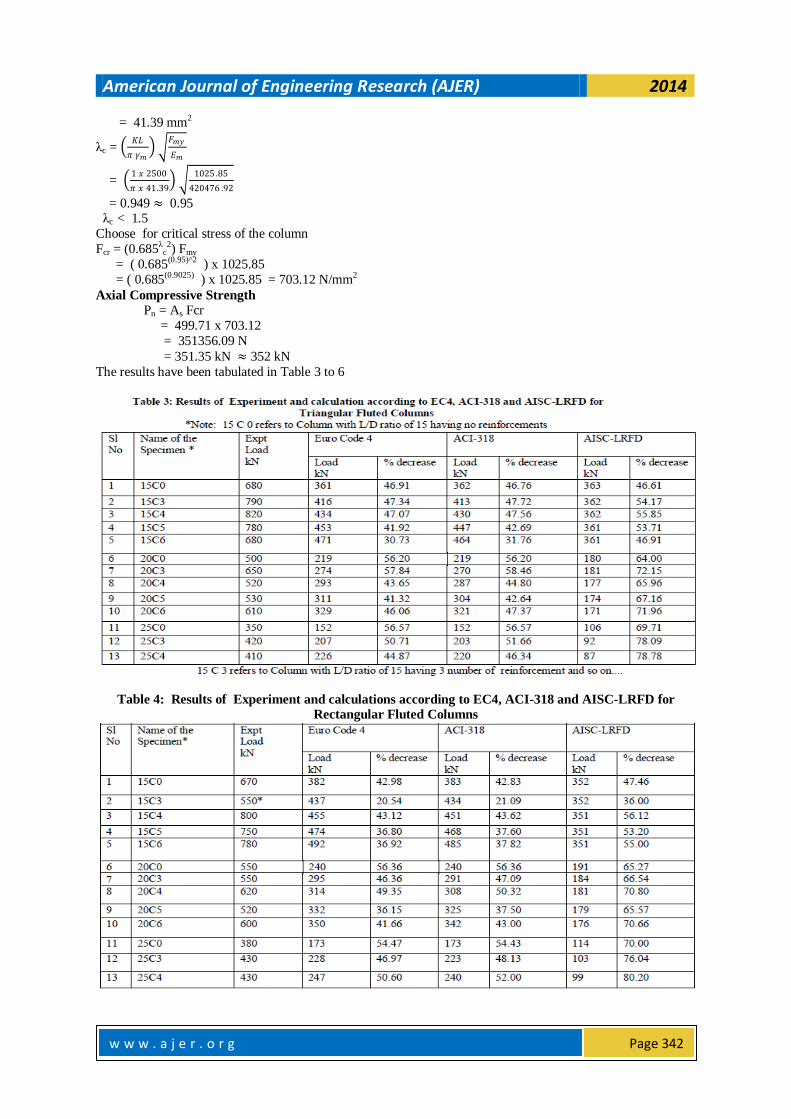
The results have been tabulated in Table 3 to 6
Table 4: Results of Experiment and calculations according to EC4, ACI-318 and AISC-LRFD for
Rectangular Fluted Columns

American Journal of Engineering Research (AJER) 2014
w w w . a j e r . o r g
Page 343
Table 5. Triangular Fluted Column Results of EC4 with ACI-318, EC4 with AISC-LRFD & ACI-318
with AISC-LRFD
Table 6. Rectangular Fluted Column Results of EC4 with ACI-318, EC4 with AISC-LRFD & ACI-318
with AISC-LRFD
III. CONCLUSION a. Triangular Fluted Columns
Eurocode 4, ACI-318 and AISC-LRFD equations compare well each other and the loads calculated using
these codes are about 42, 43 and 51% conservative on an average as compared to that of experimental
results for triangular fluted columns with L/D ratio of 15, only. Similarly these values are 49, 50 and 68%
for L/D ratio of 20 and 50, 51 and 75% for L/D ratio of 25.
EC4 with ACI-318 , EC4 with AISC-LRFD and ACI-318 with ASIC-LRFD are about 0.84, 14.53 &
13.86% for L/D ratio 15, 1.63, 36.68 & 35.71% for L/D ratio 20, 1.52 , 49.10 & 48.46% for L/D ratio 25 conservative on an average as compared to that of codes results for triangular fluted columns.
b. Rectangular Fluted Columns
Eurocode 4, ACI-318 and AISC-LRFD equations compare well each other and the loads calculated using
these codes are about 36, 37 and 50% conservative on an average as compared to that of experimental
results for rectangular fluted columns with L/D ratio of 15, only. Similarly these values are 46, 47 and 68%
for L/D ratio of 20 and 50, 51 and 75% for L/D ratio of 25.

American Journal of Engineering Research (AJER) 2014
w w w . a j e r . o r g
Page 344
EC4 with ACI-318 , EC4 with AISC-LRFD and ACI-318 with ASIC-LRFD are about 0.79, 20.95 &
20.35% for L/D ratio 15, 1.52, 39.23 & 38.37 % for L/D ratio 20, 1.67 , 49.61 & 48.88% for L/D ratio 25
conservative on an average as compared to that of codes results for rectangular fluted columns.
Comparison of the results of the three codes with experimental results revealed that Eurocode-4 and ACI-
318 compare well each other and are about 55% and 45% that of experimental results for triangular fluted
columns whereas AISC-LRFD yields about 35% of values of experimental results. The equations provided
in the three codes cannot be used as it is and requires modification.
IV. ACKNOWLEDGEMENT The authors wish to thank the authorities of Bangalore University for giving an opportunity to conduct
the experiments in the Structural Engineering Laboratory of Faculty of Engineering-Civil.
REFERENCE [1] Furlong RW. 1976, AISC column logic makes sense for composite columns, too. Engineering Journal,
AISC 1976;1:1-7. [2] Georgios Giakoumelis, & Dennis Lam., (2004), "Axial capacity of circular concrete-filled tube columns",
Journal of Constructional Steel Research, Vol. 60, pp. 1049-1068
[3] Liang QQ & Uy B, (2000), "Theoretical study on the post-local buckling of steel plates in concrete-
filled box columns", Computers and Structures, Vol. 75, pp 479-90.
[4] Liang QQ, (2004), "Local and post-local buckling of double skin composite panels", Proceedings
of the Institute of Civil Engineers Structures and Buildings, Vol. 156, no 2, pp 111-19.
[5] Liang QQ, Uy B.& Liew J.Y.R, (2006a), "Local buckling of steel plates in concrete -filled thin-walled
steel tubular beam-columns", Journal of Constructional Steel Research, accepted 26 May 2006a.
[6] Lin-Hai Han , Guo-Huang Yao & Zhong Tao, (2007)," Behaviors of concrete-filled steel tubular
members subjected to combined loading " , THIN-WALLED STRUCTURES 45 (2007) , pp 600-619.
[7] Mohanraj E.K & Dr. S. Kandasamy, (2008), " Experimental Behaviour of Axially Loaded Hollow Steel Columns In-filled with Concrete" 2008, IE(I) Journal-CV Vol 88, February 2008 pp 23-29.
[8] Mursi. M & B.Uy, (2003), " Strength of Concrete Filled Steel Box Columns Incorporating Interaction
Buckling", JOURNAL OF STRUCTURAL ENGINEERING, ASCE / MAY 2003, pp 626-638.
[9] Nan Su, Kung-Chung Hsu, & His-Wen Chai., (2001), "A simple mix design method for self- compacting
concrete", Cement and Concrete Research 31 (2001) 1799 – 1807.
[10] O’Shea. Martin D & Bridge Russell Q, (1997), “Local buckling of thin–walled circular steel sections
with or without internal restraint” Journal of Constructional Steel Research, Vol. 41, issues 2-3, Feb-
March 1997 pp. 137-157.
[11] O’Shea, MD & Bridge RQ, (2000), "Design of circular thin-walled concrete filled steel tubes",
Journal of Structural Engineering, ASCE, Proc. 126, 1295-1303.
[12] Pramod Kumar Gupta, V.K. Verma, M Devakinandan and A.K. Ahuja, (2013), "Experimental Study
on Axially Loaded, Concrete Filled, Unplasticised Poly Vinyl Chloride (UPVC) Tubes", ICI JOURNAL , INDIAN CONCRETE INSTITUTE, Vol. 14, July-September 2013, No.2 , pp 45-49.
[13] Shanmugam N.E & Lakshmi. B ,( 2001),"State of the art report on steel-concrete composite columns".
Journal of Constructional Steel Research 57 (2001) pp 1041-1080.
[14] Uy, B, (1998), "Local and post-local buckling of concrete filled steel welded box columns", Journal of
Constructional Steel Research , Vol. 47, pp 47-52.
[15] Uy. B, (2000), "Strength of concrete-filled steel box columns incorporating local buckling", Journal of
Structural Engineering, ASCE, Vol. 126, no, 3 pp 341-52.
[16] Uy, B, (2001), " Local and post-local buckling of fabricated steel and composite cross sections", Journal
of Structural Engineering, ASCE, vol. 127, no 6, pp 666-77.
[17] Weng C.C & Yen S.I. (2001), "Comparisons of concrete-encased composite column strength provisions
of ACI code and AISC specification", Engineering Structures 24 (2002) 59-72. [18] Zeghichea. J, and K. Chaoui, (2005), "An experimental behaviour of concrete-filled steel tubular
columns", Journal of Constructional Steel Research 61 (2005) 53–66.