comparison of concrete and steel semi-submersible floaters
TRANSCRIPT
Comparison of concrete and steel semi-submersible floaters for 10MW wind turbines
Sho OH
(ClassNK, [email protected])

Introduction
➢ Lower material cost➢ Possible contribution to local contents➢ Possible construction flexibility
Prestressed concrete (PC) is gaining interest as an alternative to steels for FOWTs for following advantages:
1/16
Concrete
• Lighter material density compared to steel. • Larger wall thickness than steel. • Various types of concrete with various material properties. Design parameters such as wall
thickness sometimes dependent on design philosophy such as crack control and corrosion protection methods rather than required strength.
Steel
• Larger material density compared to concrete• Lighter total material weight compared to concrete • Relatively constant material property
How much effect the differences in the material properties for concrete and steel can have on floater responses and floater geometries? Is there any types of concrete more suitable for FOWTs?

Objective
1. Design a basic geometry of semi-submersible type floater with several geometrical variables to conduct sensitivity study.
2. Chose typical material properties for concrete and steel, and study the characteristics of the pitch response and suitable floater geometry for each material.
3. Estimate possible material cost range for the three types of material
2/16
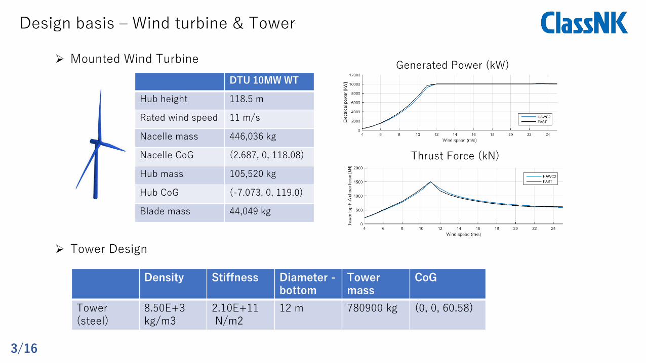
Design basis – Wind turbine & Tower
➢ Mounted Wind TurbineGenerated Power (kW)
Thrust Force (kN)
➢ Tower Design
Density Stiffness Diameter -bottom
Tower mass
CoG
Tower(steel)
8.50E+3kg/m3
2.10E+11N/m2
12 m 780900 kg (0, 0, 60.58)
DTU 10MW WT
Hub height 118.5 m
Rated wind speed 11 m/s
Nacelle mass 446,036 kg
Nacelle CoG (2.687, 0, 118.08)
Hub mass 105,520 kg
Hub CoG (-7.073, 0, 119.0)
Blade mass 44,049 kg
3/16

Design basis – Metocean conditions
10 min mean wind speed(50 years,60 m height)
48.3 m/s
Wind shear in ultimate condition 0.1
Reference turbulence intensity 0.12%
Significant wave height (50 years) 11.71 m
Significant wave height (50 years) 13.0 s
Max. tidal level C.D.L. + 2.77 m
➢ Ultimate conditions ➢ Fatigue conditions
➢ Target site
4/16

Basic geometry of the semi-sub floater
• Simplicity of the structural and hydrodynamic modelling• Easier to install/model prestressed steel
Basic geometry was designed considering:
Larm
Lsc
x
y
Lsc
x
z
y
10m
20m
Hlh
MSL
Lsc Lsc
Larm
3.5m
• Side column width (Lsc) • Hull length (Larm)• Lower hull height (Hlh)
Floater geometric variables for sensitivity study:
5/16

NormalConcrete
LightweightConcrete Steel
MaterialDensity 2500 kg/m3 1800 kg/m3 7874kg/m3
Wall thickness 350 - 550 mm 350 - 550 mm 16 – 40 mm
Ballast density(Water) 1025 kg/m3 1025 kg/m3 1025 kg/m3
Design basis – Material properties
Simplified initial design based on Standard for Structural Design and Construction of Prestressed Concrete Structures, Architectural Institute of Japan (1998)
Parameters contributing to concrete wall thickness
・RC/PC Steel cover・Minimum distance between PC sheath and RC steel・Minimum distance between RC steels..etc
which are affected by concrete material type,anticorrosion methods, control of cracks etc.
Sheath
RC steel
Shear reinforcement
6/16

CoG of the total system
x
z
y
10m
20m
Hlh
MSL
Lsc Lsc
Larm
Normal Concrete
SteelLightweight Concrete
Lsc Larm Hlh
• Larger values for Lsc, Larm and Hlh result in lower total CoG for all material types. • Lightweight concrete and steel give lower total CoG compared to normal concrete.
Lsc LscLarm Larm
7/16
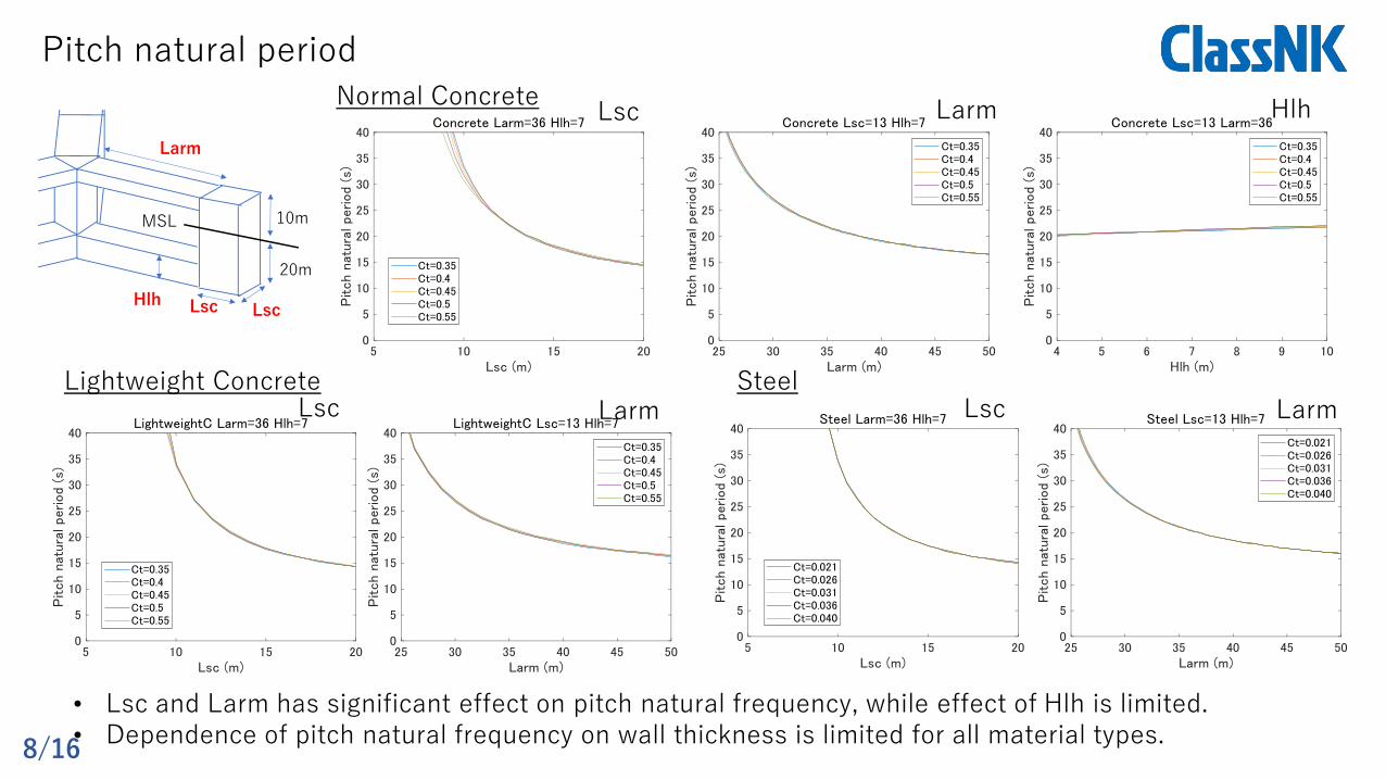
Pitch natural periodx
z
y
10m
20m
Hlh
MSL
Lsc Lsc
Larm
Normal Concrete
SteelLightweight Concrete
Lsc Larm Hlh
Lsc Larm Lsc Larm
• Lsc and Larm has significant effect on pitch natural frequency, while effect of Hlh is limited. • Dependence of pitch natural frequency on wall thickness is limited for all material types.
8/16

Frequency domain analysis
➢ Wind response(𝑃𝑖𝑡𝑐ℎ𝑤𝑖𝑛𝑑)➢ Wave response (𝑃𝑖𝑡𝑐ℎ𝑤𝑎𝑣𝑒)
𝑀𝐺 ሷ𝑢𝐺 + 𝐶𝐺 ሶ𝑢𝐺 + 𝐾𝐺𝑢𝐺 = 𝐹ℎ𝑑𝑟𝑜
𝑀𝐺 =
𝑖
𝑇𝑖𝑇(𝑀𝑖+𝑀𝑎,𝑖)𝑇𝑖 𝐹ℎ𝑦𝑑𝑟𝑜 =
𝑖
𝑇𝑖𝑇𝑓ℎ𝑦𝑑𝑟𝑜,𝑖
𝜂 = acos(𝜅𝑋 − 𝜔𝑡)
Equation of motion
Wave excitation force
CoG
i-th Member
𝑧0𝑧2
𝑓ℎ𝑦𝑑𝑟𝑜,𝑖
≈ 𝜌𝑔𝐴𝑤𝜂 + න−(𝑧0−𝑧2)
𝑧2
(𝜌𝐴𝑤 +𝑚𝑎𝑧)𝜕2𝜑
𝜕𝑡𝜕𝑧𝑑𝑧
Coordinate transformation matrix for i-th member
𝜑 = 𝑐𝑎𝑒𝑘𝑧sin(𝜅𝑋 − 𝜔𝑡)
Airy wave theory
𝑃𝑖𝑡𝑐ℎ𝑤𝑎𝑣𝑒 = max[𝑃𝑖𝑡𝑐ℎ𝑤𝑎𝑣𝑒 𝑇𝑠 = 12.0𝑠 , 𝑃𝑖𝑡𝑐ℎ𝑤𝑎𝑣𝑒 𝑇𝑠 = 13.0𝑠 , 𝑃𝑖𝑡𝑐ℎ𝑤𝑎𝑣𝑒 𝑇𝑠 = 14.0𝑠 ]
𝑃𝑖𝑡𝑐ℎ𝑡𝑜𝑡𝑎𝑙 = 𝑃𝑖𝑡𝑐ℎ𝑤𝑎𝑣𝑒 + 𝑃𝑖𝑡𝑐ℎ𝑤𝑖𝑛𝑑
Thrust force1824.36kN(Onshore max)
20 m
Restoring moment:
119 m
9/16

◼ Time domain analysis
𝑀 ሷ𝑢 + 𝐶 ሶ𝑢 + 𝐾𝑢 = 𝐹ℎ𝑦𝑑𝑟𝑜 + 𝐹𝑙𝑖𝑛𝑒𝑠 + 𝐹𝑏𝑢𝑜𝑦𝑎𝑛𝑐𝑦 + 𝐹𝑎𝑒𝑟𝑜
Verification of frequency domain analysis
Pitch RAO Pitch Irregular wave responseHeave RAO
Verification case;Lsc=12m, Larm=36m, Hlh=7m, Hs=11.3m, Ts=14.3s, Cax=1.1, Caz=0.5
𝐹ℎ𝑦𝑑𝑟𝑜 = 𝜌𝜋𝐷2
4ሷ𝑢 + 𝐶𝑚𝜌
𝜋𝐷2
4ሷ𝑢 − ሷ𝑥 + 𝐶𝐷
1
2𝜌𝐷( ሶ𝑢 − ሶ𝑥) ሶ𝑢 − ሶ𝑥
10/16
x
z
y
10m
20m
Hlh
MSL
Lsc Lsc
Larm
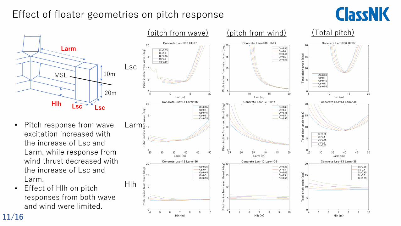
Effect of floater geometries on pitch response
Lsc
Larm
Hlh
(pitch from wave) (pitch from wind) (Total pitch)
• Pitch response from wave excitation increased with the increase of Lsc and Larm, while response from wind thrust decreased with the increase of Lsc and Larm.
• Effect of Hlh on pitch responses from both wave and wind were limited.
11/16
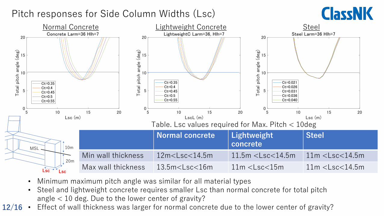
Pitch responses for Side Column Widths (Lsc)
Normal Concrete SteelLightweight Concrete
Normal concrete Lightweight concrete
Steel
Min wall thickness 12m<Lsc<14.5m 11.5m <Lsc<14.5m 11m <Lsc<14.5m
Max wall thickness 13.5m<Lsc<16m 11m <Lsc<15m 11m <Lsc<14.5m
Table. Lsc values required for Max. Pitch < 10deg
10m
20m
MSL
Lsc Lsc
• Minimum maximum pitch angle was similar for all material types• Steel and lightweight concrete requires smaller Lsc than normal concrete for total pitch
angle < 10 deg. Due to the lower center of gravity?• Effect of wall thickness was larger for normal concrete due to the lower center of gravity?12/16

Pitch responses for Hull Lengths (Larm)
Normal concrete Lightweight concrete
Steel
Min wall thickness 31m <Larm<42m 30m <Larm<41m 28m<Larm<40m
Max wall thickness 37m <Larm<46m 32m <Larm<44m 28m<Larm<40m
Table. Larm values required for Max. Pitch < 10deg
Normal Concrete SteelLightweight Concrete
10m
20m
MSL
Larm
• Minimum maximum pitch angle was similar for all material types• Steel requires smaller Larm than normal concrete for total pitch angle < 10 deg. • Effect of wall thickness was large for normal concrete but limited for steel floaters 13/16

Pitch responses for Hull Heights (Hlh)
Normal Concrete SteelLightweight Concrete
10m
20m
Hlh
MSL
• Effect of Hlh is limited for all material types• Consideration of the three wave periods can limit
the effect of the position of the waveless point
𝑃𝑖𝑡𝑐ℎ𝑤𝑎𝑣𝑒= max[𝑃𝑖𝑡𝑐ℎ𝑤𝑎𝑣𝑒 𝑇𝑠 = 12.0𝑠 , 𝑃𝑖𝑡𝑐ℎ𝑤𝑎𝑣𝑒 (
)𝑇𝑠
= 13.0𝑠 , 𝑃𝑖𝑡𝑐ℎ𝑤𝑎𝑣𝑒 𝑇𝑠 = 14.0𝑠 ]
14/16

Material costs for possible designs
Normal Concrete SteelLightweight Concrete
Material weight Unit material cost Total material cost
Normal Concrete(2500kg/m3)
1.2e+7 ~2.0e+7 kg 30,000 yen/m3 (230€/m3) 144,000,000 - 240,000,000 yen(1,110,000 - 1,850,000 €)
Lightweight Concrete(1800kg/m3)
0.8e+7 ~1.5e+7 kg 60,000 yen/m3 (460€/m3) 267,000,000 - 500,000,000 yen(2,050,000 - 3,850,000 €)
Steel(7874kg/m3)
2.0e+6 ~4.5e+6 kg 90,000 yen/ton (690€/ton) 1,800,000,000 – 4,050,000,000 yen(13,800,000 - 31,200,000 €)
15/16

Conclusion
In this study, the characteristics of response of a-semi-submersible floater for 10 MW wind turbine are studied for concrete and steel, and following conclusions are obtained:
1. Minimum maximum pitch angles was similar for all material types
2. The optimum hull length and column widths for steel floaters is generally smaller than those for concrete floaters, which is mainly due the lighter material weight that result in lower center of gravity. The optimum hull length and column widths for light-weight concrete floaters were smaller than normal concrete floaters.
3. Effect of wall thickness on floater pitch response was the largest for normal concrete among the three material types. This is mainly due to the amount of contribution of the wall thickness on the weight and height of the water ballast. Larger wall thickness resulted in larger optimum hull length and column widths for normal and lightweight concrete floaters.
4. When max pitch<10 deg is used as design index, the material cost for concrete floaters is about one-tenth of the cost for steel floaters.
The comparison conducted in this study only considered floater pitch motion. Further study need to be conducted on structural feasibility considering the material stiffness.
16/16