comparison between different antenna designs operating at
TRANSCRIPT
Contemporary Engineering Sciences, Vol. 8, 2015, no. 12, 507 - 523
HIKARI Ltd, www.m-hikari.com
http://dx.doi.org/10.12988/ces.2015.55152
Comparison between Different Antenna Designs
Operating at Different Frequencies for
GPS Applications
Ahmad N. H. Qubaia, Yahya S. H. Khraisat and Osama M. F. Al-Faqeer
Department of Electrical and Electronics, Al-Huson University College
Al-Balqa’ Applied University, P.O. Box 50, Al-Huson 21510, Jordan
Correspondence to: Yahya S. H. Khraisat, Department of Electrical and
Electronics Engineering, Al-Huson University College, Al-Balqa’ Applied
University, PO Box 50, Al-Huson 21510, Jordan Copyright © 2015 Ahmad N. H. Qubaia et al. This article is distributed under the Creative
Commons Attribution License, which permits unrestricted use, distribution, and reproduction in
any medium, provided the original work is properly cited.
Abstract
A wearable antenna is meant to be a part of the clothing used for communication
purposes, which includes tracking, navigation, mobile computing and public
safety. We described the design and development of rectangular array patch
antennas. In this paper, several designs of microstrip arrays antennas, suitable
for interaction between antenna and human body, are presented. We presented
two antennas with different geometry and frequencies but both have operation
point for GPS application. Specifically, 2x1, 2x2, 2x4 and single element are
designed and simulated by a full wave simulator (IE3D). Moreover, this paper
presents a comparison between both rectangular and square antenna arrays. The
resonance frequency for square antenna is 1.3GHz and for rectangular is 1.575
GHz.
In this paper, Inset feed techniques are applied to the rectangular microstrip patch
antenna.
Keywords: microstrip antenna array, rectangular microstrip antenna, square
microstrip antenna, resonant gain, Return loss, 3D radiation
508 Ahmad N. H. Qubaia et al.
1. Introduction
The design of microstrip patch antenna with high gain suitable for GPS
applications is described in [1].
Microstrip antenna has been widely used in radio equipments from 100MHz to
100GHz, especially for the devices in the aircraft and ground portable devices.
Microstrip antennas are often given priority for the application which low profile
radiators are required, even if some performances are not as good as the general
antennas.
The Objective of this system is to increase MPA compatible with human body
and improve characteristics of antenna like gain, return loss, bandwidth and beam
width. This antenna is fabricated with clothes of soldier. This antenna is called
“Wearable Antenna for GPS Applications”.
2. Antenna Array
We can use single patch antenna but in order to improve the performance of the
antenna we will investigate antenna arrays. We will use 2x1, 2x2 and 2x4 antenna
arrays. Our designed antenna operates in two frequencies 1.3GHz and 1.575GHz.
We selected relative dielectric constant ε = 2.2 and the thickness h of substrate to
be 3.175mm for all designed described below.
We evaluated the length, width and the input impedance of the patch. Then we
investigated radiation patterns, reflected loss, efficiency and antenna gain using
electromagnetic simulator IE3D.
2.1 Antenna Array Design
2.1.1 Design and Network Analysis for single Antenna
The design of single patch antenna is shown below in figure 1. Specified by
calculating the half wavelength value and then subtracting a small length to take
into account the fringing fields [2-4]
We chose patch length L = 76mm
Patch width =76 mm
Patch width of 50 Ω line = 2 mm
Patch Length of the 50 Ω line = 25 mm
Patch Width of the 50 Ω line = 15 mm
Patch Length of the 50 Ω line = 30 mm

Comparison between different antenna designs 509
Figure 1. Geometry of Single Microstrip antenna array with Inset feed.
2.1.2 Design and Network Analysis for 2x1 Antenna Array The design of 2x1 antenna array is shown below in figure 2.
Length and width of the Patch 76 mm
Width of the 50 Ω line = 4 mm
Length of the 50 Ω line = 8 mm
Figure 2. Geometry of 1x2 Microstrip antenna array with Inset feed.

510 Ahmad N. H. Qubaia et al.
2.1.2 Design and Network Analysis for 2x2 Antenna Array The design of 2x2 patch array is shown below in figure 3.
Figure 3. Geometry of 2x2 Microstrip antenna array with Inset feed.
2.1.3 Design and Network Analysis for 2x4 Antenna Array The design of 2x4 antenna array is shown below in figure 4.
Length and width of the Patch = 76 mm
Width of the 50 Ω line = 20 mm
Length of the 50 Ω line = 48 mm
Figure 4. Geometry of 2x4 Microstrip antenna array with Inset feed.

Comparison between different antenna designs 511
3. Results on Performance Characteristic of Wearable Antenna
3.1 Return Loss Characteristics
The inset feed [5, 6] is used in the design for single, 1x2, 2x2 and 2x4 Microstrip
array antennas. Figures 5, 6, 7 and 8 demonstrate the return loss of single
microstrip patch antenna, 2x1, 2x2 and 2x4 respectively. The excitation for
antenna happened at -10 dB, at this value, the antenna switched on.
Figure 5. Return Loss Characteristics single Microstrip antenna.
Figure 6. Return Loss Characteristics 1x2 Microstrip array antenna.

512 Ahmad N. H. Qubaia et al.
Figure 7. Return Loss Characteristics 2x2 Microstrip array antenna.
Figure 8. Return Loss Characteristics 2x4 Microstrip array antenna.
Summary of results of simulation are shown below in table 1
Table 1: Comparing between single, 1x2, 2x2 and 2x4 Microstrip array antenna
Array/Dimension Resonant
Frequency
(GHz)
Bandwidth
(MHz)
S11 parameter
(dB)
Single 1.31 17 MHz -30.498
1x2 1.3 12 MHz -13.125
2x2 1.28 35 MHz -35.59

Comparison between different antenna designs 513
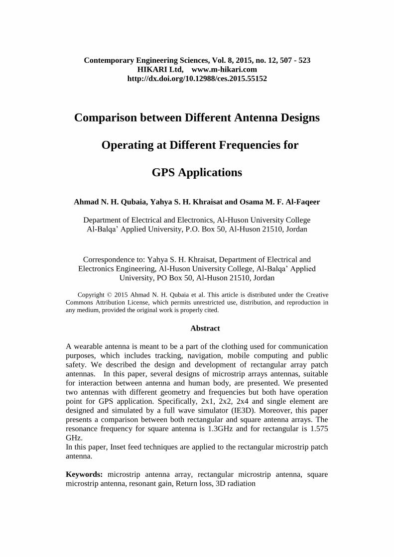
3.2 Far-field Radiation Pattern Characteristics Figures 9, 10, 11 and 12 show the radiation pattern of inset feed for the antennas
(Single, 1x2, 2x2 and 2x4).
After we simulated we get the value of return loss and we get the operating
frequency.
At this frequency, we get the maximum gain.
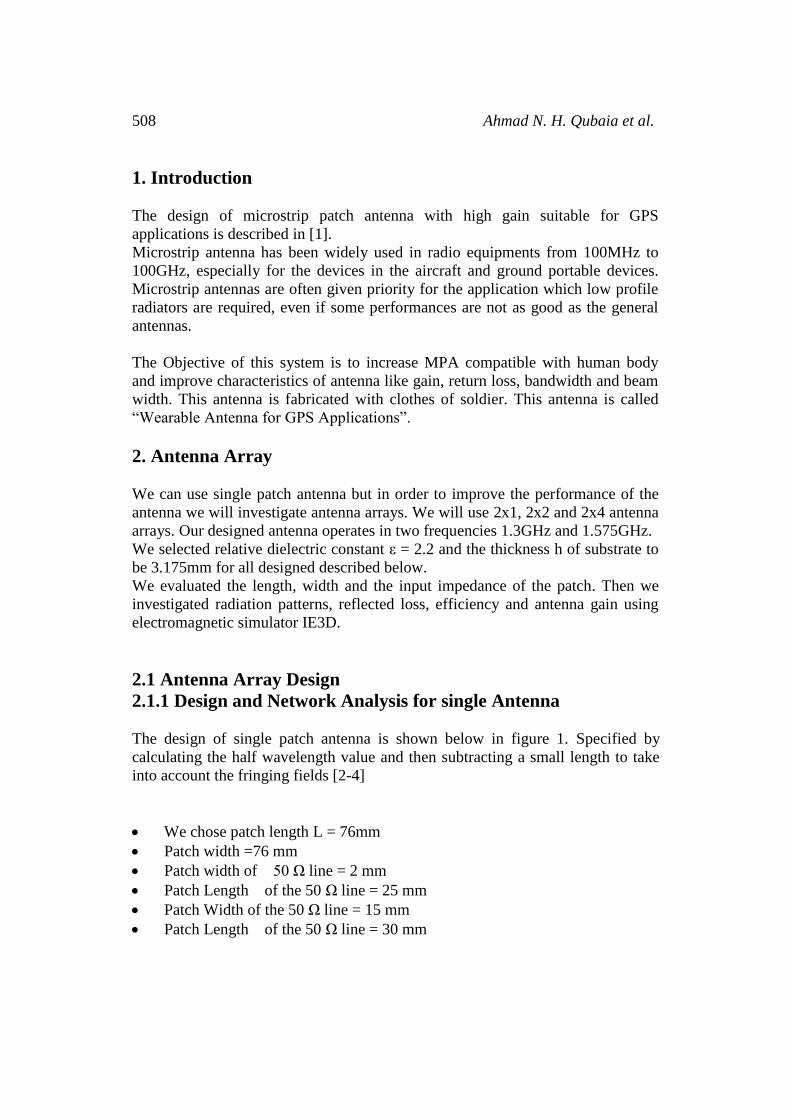
We consider as the element (antenna) is increased, the gain is increase and the
beam-width is decreased. But we must know when we use array antenna the side
lob is increased. To avoid this problem we increase the space between radiating
elements.
Figure 9: Single Antenna 3D radiation pattern for inset feed
Figure10: 1x2 Antenna 3D radiation pattern for inset feed
514 Ahmad N. H. Qubaia et al.
Figure 11: 2x2 Antenna 3D radiation pattern for inset feed
Figure 12: 2x4 Antenna 3D radiation pattern for inset feed
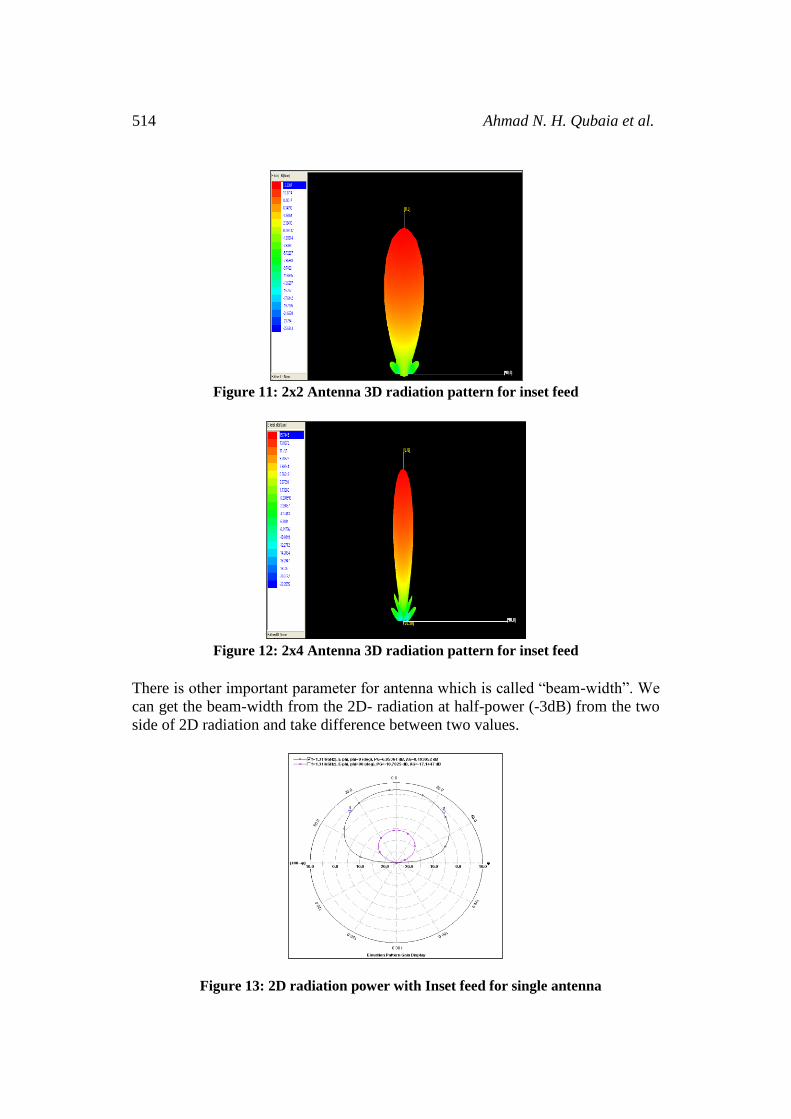
There is other important parameter for antenna which is called “beam-width”. We
can get the beam-width from the 2D- radiation at half-power (-3dB) from the two
side of 2D radiation and take difference between two values.
Figure 13: 2D radiation power with Inset feed for single antenna

Comparison between different antenna designs 515
Figure 14: 2D radiation power with Inset feed for 1x2 antenna
Figure 15: 2D radiation power with Inset feed for 2x2 antenna
Figure 16: 2D radiation power with Inset feed for 2x4 antenna

516 Ahmad N. H. Qubaia et al.
Table 2: Essential parameter of Single, 1x2, 2x2 and 2x4
Array/Dimension Gain (dBi) 3 dB beam-width
Single 7.03 84.259 º
1x2 9.627 43.46 º
2x2 12.31 47.528º
2x4 15.74 23.5º
There’s another frequency used for GPS which is 1.575 GHz. We will compare
between two frequencies (1.3 GHz and 1.575 GHz) with different antenna
parameters: Return loss, gain, bandwidth and beam-width.
4. Antenna Array Design
4. 1 Design and Network Analysis for single Antenna Antenna design for a single patch antenna with inset feed is shown below in figure
17.
Length and width of the Patch = 64.1 mm
Width of the 50 Ω line = 2 mm
Length of the 50 Ω line = 25 mm
Figure 17. Geometry of Single Microstrip antenna array with Inset feed.
4.2 Design and Network Analysis for 2x1 Antenna Array Antenna design for 2x1 patch antenna with inset feed is shown below in figure 18
Length and width of the Patch = 76 mm
Width of the 50 Ω line = 4 mm
Length of the 50 Ω line = 8 mm
Comparison between different antenna designs 517
Figure 18. Geometry of 1x2 Microstrip antenna array with Inset feed.
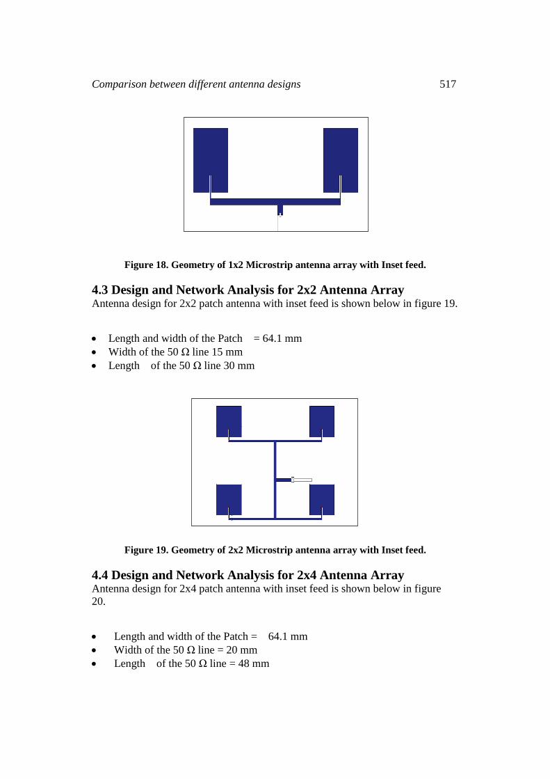
4.3 Design and Network Analysis for 2x2 Antenna Array Antenna design for 2x2 patch antenna with inset feed is shown below in figure 19.
Length and width of the Patch = 64.1 mm
Width of the 50 Ω line 15 mm
Length of the 50 Ω line 30 mm
Figure 19. Geometry of 2x2 Microstrip antenna array with Inset feed.
4.4 Design and Network Analysis for 2x4 Antenna Array Antenna design for 2x4 patch antenna with inset feed is shown below in figure
20.
Length and width of the Patch = 64.1 mm
Width of the 50 Ω line = 20 mm
Length of the 50 Ω line = 48 mm

518 Ahmad N. H. Qubaia et al
Figure 20. Geometry of 2x4 Microstrip antenna array with Inset feed.
5. Results on Performance Characteristic of Wearable Antenna
5.1Return Loss Characteristics The inset feed is designed for single, 1x2, 2x2 and 2x4 Microstrip array antennas.
Figures 21, 22, 23 and 24 demonstrate the return loss of single, 2x1, 2x2 and 2x4
antenna arrays
Figure 21. Return Loss Characteristics single Microstrip antenna.
Figure 22. Return Loss Characteristics 1x2 Microstrip array antenna.
Comparison between different antenna designs 519
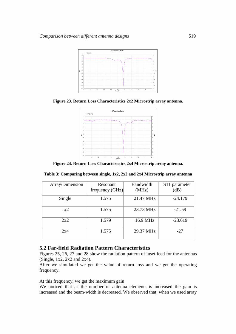
Figure 23. Return Loss Characteristics 2x2 Microstrip array antenna.
Figure 24. Return Loss Characteristics 2x4 Microstrip array antenna.
Table 3: Comparing between single, 1x2, 2x2 and 2x4 Microstrip array antenna
Array/Dimension Resonant
frequency (GHz)
Bandwidth
(MHz)
S11 parameter
(dB)
Single 1.575 21.47 MHz -24.179
1x2 1.575 23.73 MHz -21.59
2x2 1.579 16.9 MHz -23.619
2x4 1.575 29.37 MHz -27
5.2 Far-field Radiation Pattern Characteristics Figures 25, 26, 27 and 28 show the radiation pattern of inset feed for the antennas
(Single, 1x2, 2x2 and 2x4).
After we simulated we get the value of return loss and we get the operating
frequency.
At this frequency, we get the maximum gain
We noticed that as the number of antenna elements is increased the gain is
increased and the beam-width is decreased. We observed that, when we used array

520 Ahmad N. H. Qubaia et al
antenna the side lob is increased. To avoid this problem we increase the space
between radiating element.
Figure 25: single Antenna 3D radiation pattern for inset feed
Figure 26: 1x2 Antenna 3D radiation pattern for inset feed
Figure 27: 2x2 Antenna 3D radiation pattern for inset feed

Comparison between different antenna designs 521
Figure 28: 2x4 Antenna 3D radiation pattern for inset feed
There is other important parameter for antenna which is “beam-width”. We can
get the beam-width from the 2D- radiation at half-power (-3dB) from the two side
of 2D radiation and taken the difference between two values.
Figure 29: 2D radiation power with Inset feed for single antenna
Figure 30: 2D radiation power with Inset feed for 1x2 antenna

522 Ahmad N. H. Qubaia et al
Figure 31: 2D radiation power with Inset feed for 2x2 antenna.
Figure 32: 2D radiation power with Inset feed for 2x4 antenna
Table 4: Essential parameter of Single, 1x2, 2x2 and 2x4
Array/Dimension Gain (dBi) 3 dB beam-width
Single 6.07 88.93 1x2 9.98 37.27
2x2 12.92 44.286
2x4 15.50 22.6
6. Conclusion
Finally, we noticed after we have viewed all simulated parameters for two
operating frequencies 1.3GHz and 1.575GHz that the efficiency and the best
geometry was the antenna with 1.575GHz. In one hand, the Beam-width must be
smaller because with satellite the beam-width at 2 x 4 array antenna for 1.3GHz is
23.5° but the beam- width for 1.575 GHz at 2 x 4 array antenna is 22.6°.On the
other hand, the gain at 1.3 GHz for 2 x 4 antenna is larger than the gain at 1.575
GHz in the same dimension and it equal to 15.74 dBi.

Comparison between different antenna designs 523
References
[1] Yahya S. H. Khraisat, Design of 4 elements rectangular microstrip patch
antenna with high gain for 2.4 GHz applications, Modern Applied Science,
Canadian Centre of Science and Education, 2011, Vol. 6, No. 1, January 2012,
68-74. http://dx.doi.org/10.5539/mas.v6n1p68
[2] M. Schneider, Microstrip lines for microwave integrated circuits, Bell Syst.
Tech. J., 48, 1969, 1421-1444.
http://dx.doi.org/10.1002/j.1538-7305.1969.tb04274.x
[3] A. Derneryd, Linearly polarized microstrip antennas, IEEE Trans. Antennas
and Propagation, AP-24, 1976, 846-851.
http://dx.doi.org/10.1109/tap.1976.1141445
[4] J. R. James, P. S. Hall and C. Wood, Microstrip Antenna Theory and Design,
London, UK: Peter Peregrinus, 1981. http://dx.doi.org/10.1049/pbew012e
[5] I. J. Bahl and P. Bhartia, Microstrip Antennas, Dedham, MA: Artech House,
1980.
[6] E. Hammers tad, F. A. Bekkadal, Microstrip Handbook, ELAB report, STF 44
A74169, University of Trondheim, Norway, 1975.
Received: May 1, 2015; Published: May 20, 2015