comparative study of coaxial main rotor aerodynamics in
TRANSCRIPT
J. Aerosp. Technol. Manag., São José dos Campos, v13, e1821, 2021
https://doi.org/10.1590/jatm.v13.1210 ORIGINAL PAPER
ABSTRACTThe paper is focused on numerical modeling of the aerodynamic characteristics of a full-scale coaxial main rotor in hover.
The simulation was performed using two approaches of computational fluid dynamics (CFD): the original free wake model (FWM) developed by the authors and the unsteady Reynolds-averaged Navier–Stokes (URANS) equations method based on the Ansys Fluent software. The structure of the rotor vortex wake, flow images, vorticity and induced velocity fields, total and distributed aerodynamic characteristics of the rotor, including the rotor performance and figure of merit diagrams, have been analyzed. A comparison between FWM/URANS based calculations and calculated/experimental data by other authors has been performed. A satisfactory match of these data confirms reliability of used methods when modeling the aerodynamic characteristics of coaxial rotors. The FMW demonstrates a significant advantage in speed and resources intensity when calculating the total aerodynamic characteristics of a coaxial rotor. The URANS method makes it possible to model with significant accuracy the effects associated with the blade vortex interactions and pressure distribution over the blade surface. Finally, conclusions about most effectiveness of joint application of considered methods in solving complex problems of coaxial rotor aerodynamics has been made.
Keywords: Coaxial main rotor; Hover; CFD; URANS method; Free wake model.
Comparative Study of Coaxial Main Rotor Aerodynamics in the Hover with the Usage of Two Methods of Computational Fluid DynamicsSergey Gennadievich Konstantinov1 , Yuri Mikhailovich Ignatkin1 , Pavel Viacheslavovich Makeev1 , Sergey Olegovich Nikitin1,*
1.National Research University – Moscow Aviation Institute – Helicopter Design Department – Moscow – Russia.
*Corresponding author: [email protected]
INTRODUCTION
The coaxial main rotor, consisting of a pair of rotors mounted on one axis and rotating in different directions, has been the feature of the Kamov company helicopters for more than 70 years. According to the coaxial main rotor scheme, almost the whole model line of Kamov helicopters was created, from the Ka-8 to the Ka-52. The absence of the power consumption on the rotation of the tail rotor and a number of other advantages of the coaxial main rotor allowed coaxial helicopters to hold their place in the
Received: Jul. 29 2020 | Accepted: Jan. 11 2021Peer Review History: Double Blind Peer Review.Section Editor: Juan Pablo Salazar
This is an open access article distributed under the terms of the Creative Commons license.
J. Aerosp. Technol. Manag., São José dos Campos, v13, e1821, 2021
Konstantinov SG, Ignatkin YM, Makeev PV, Nikitin SO2
global helicopter fleet. At the same time, the special features of the coaxial main rotor scheme in horizontal flight made it the basis for the advanced blade concept (ABC) technology first implemented by the Sikorsky Aircraft company in the S-69 high-speed helicopter demonstrator. Since then, the coaxial main rotor has become the basis for many high-speed helicopter projects, which has significantly increased interest in this aerodynamic scheme of the main rotor. Therefore, coaxial rotor aerodynamics has been the subject of a large number of researches and nowadays it does not lose its relevance.
A number of experimental works in wind tunnels (WT) and on special experimental stands were focused on the study of coaxial rotor aerodynamics (Harrington 1951; Nagashima and Nakanishi 1983; Coleman 1997). The experimental studies and flight tests have been conducted by TSAGI and Kamov company starting from the 1950s (Bourtsev et al. 2001; Petrosian 2004).
In recent years, numerical modeling of aerodynamics has taken an increasing place in the process of creating and improving aircraft. This is primarily due to the growing capabilities of computer technology, which allows implementing in practice mathematical models that adequately represent the complex physical processes of flow around various elements of aircraft. The use of numerical modeling in solving problems of rotorcraft aerodynamics makes it possible to supplement significantly and replace partially model experimental tests in WT and flight tests. Everything mentioned above applies to helicopters, since the calculation of the aerodynamic characteristics of the main rotor is one of the most difficult problems of aerodynamics, especially in flight modes, when the structure of the vortex wake behind the rotor is significantly nonlinear and nonstationary.
Currently, there are two main approaches in numerical modeling of helicopter rotor aerodynamics that belong to the class of computational fluid dynamics (CFD) methods. These are approaches based on various free vortex wake models and based on the solution of Navier–Stokes equations by the finite volume method (FVM) using various turbulence models.
Modern vortex models represent a vortex wake behind a rotor in a nonstationary and nonlinear setting. This allows to model accurately the field of induced velocities around the rotor and the interaction of vortex of the rotor wake, which is especially important in the study of coaxial rotors. Many recent researches study coaxial rotor aerodynamics on the basis of various vortex models (Yana and Rand 2012; Singh and Friedmann 2017; Fernandes 2017; Ignatkin et al. 2018; Tan et al. 2018; Kritsky et al. 2020). Also, it is possible to mention the work performed on the basis of the original vorticity transport model (VTM) (Kim and Brown 2010). It should be noted that, in general, vortex models are not too demanding on computing resources and are often able to solve applied problems of helicopter rotor aerodynamics using conventional personal computers.
The main problem of FVM based CFD methods is the simulation of turbulent flows. To date, there are no universal turbulence models that can cover all the turbulence scales. Currently, there are four main directions of solving the problem of modeling turbulent flows. Firstly, there is the direct numerical simulation (DNS), which is a method for solving unsteady Navier–Stokes equations without any turbulence models (Moin and Mahesh 1998). Secondly, it is necessary to mention the method for solving unsteady Reynolds-averaged Navier–Stokes (URANS) equations using algebraic or differential turbulence models (Menter 1993; Wilcox 1994; Spalart and Allmaras 1992). Next is the large eddy simulation (LES) method based on the solution of unsteady Navier–Stokes equations with modeling the effect of sub-grid scale vortex (Ferziger 2000). Finally, there is the method of detached eddy simulation (DES), which is a combination of two approaches mentioned above, where URANS is used in the external flow zone and LES is used in the flow separation zone with large eddies (Strelets 2001).
Finite volume method based CFD methods require powerful supercomputer clusters for solving problems of helicopter rotor aerodynamics. The URANS method is currently used more often, as it is the least resource-intensive. Now, the URANS method is successfully used both for calculating single (Ignatkin and Konstantinov 2012; Garipova et al. 2014; Ridhwan et al. 2017; Abalkin et al. 2020) and coaxial rotors (Deng et al. 2019; Dacheng et al. 2019; Kinzel et al. 2019). Less often, the DES method is used (Dehaeze et al. 2018).
The present work is focused on numerical modeling and comparative analysis of the aerodynamic characteristics of a coaxial main rotor based on two calculation methods: the free wake model (FWM), developed by the authors Ignatkin et al. (2009) and the URANS method, based on the Ansys Fluent software. This approach allows evaluating possibilities and perspectives of using both models to solve problems of a helicopter coaxial main rotor aerodynamics. The results obtained also serve as validation of the FWM.
J. Aerosp. Technol. Manag., São José dos Campos, v13, e1821, 2021
Comparative Study of Coaxial Main Rotor Aerodynamics in the Hover with the Usage of Two Methods of Computational Fluid Dynamics 3
THE OBJECT OF STUDY AND ASSUMPTIONS
This paper considers the coaxial main rotor of Ka-226 helicopter (Vassiliyev et al. 2007; Bourtsev et al. 2007). The coaxial main rotor structurally consists of two rotors: upper rotor (UR) and lower rotor (LR) with the same radius located one above other on the same axis of rotation and rotating in different directions. The planes of rotation of the rotors are separated by a distance h. The blades of the rotor are rectangular in shape in the plan view and have a blade twist. The main parameters of the rotor (Bourtsev et al. 2007) are shown in Table 1.
Table 1. Parameters of the rotor under study.
Abbreviation Name Value Measure unit
Nb Number of blades 3 × 2 -
ωR Speed of the blade tips 192.6 m/s
R Rotor radius 6.5 m
c Blade chord 0.26 m
σ Rotor solidity, Nbc/πR; 0.0764 -
θtw Blade twist -8.17 °
h UR/LR rotor hub distance 1.142 m
The aerodynamic characteristics of the rotor in hovering modes are determined for the range of blade pitch angles of the upper and lower rotor blades in the range of blade pitch angles θ = 6−16°. Blade pitch angles of the upper θUR and lower θLR rotor blades are selected so that upper and lower rotors are balanced by the values of rotor torque Q. The required blade pitch angles of the upper and lower rotors were previously calculated with the rapidly FWM method and then applied in the URANS method. This significantly reduced the calculation time on the base of high resource-intensive URANS approach.
For both calculation methods, the rotor blades were modeled to be absolutely rigid for bending and twisting. At hover, the blades of the upper and lower rotors rotate with fixed cone angles, depending on the operating mode of the rotor. Used models include this point. In the FWM based calculations, the blade cone angles were determined by the solution of the blade flapping motion equations. The calculation of the blade flapping motion was not implemented in the URANS method. On each of the calculation modes, the blades were initially installed with the cone angles defined on the base of FWM calculations.
The description of the FWM and URANS methods used for numerical study are given in the following sections.
FREE WAKE MODEL
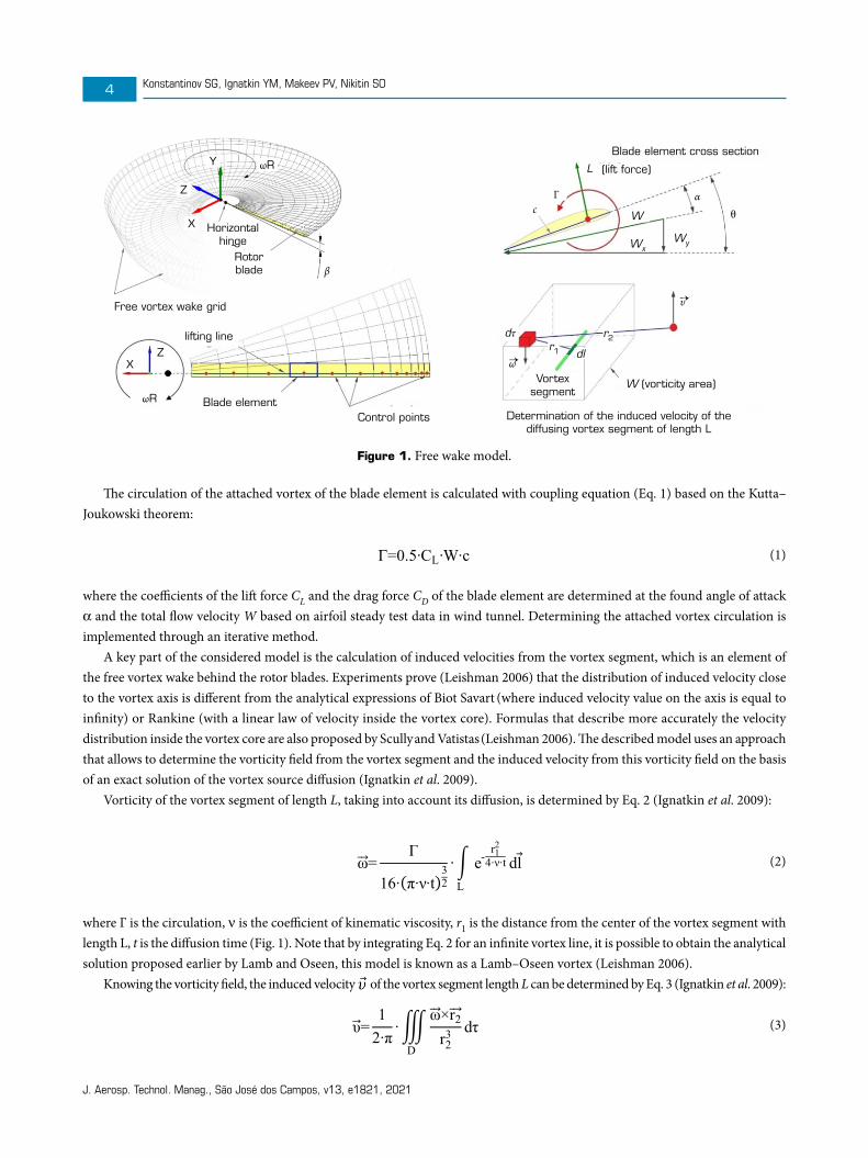
The FWM of the rotor (Ignatkin et al. 2009) developed at the Helicopter Design Department of the Moscow Aviation Institute is based on the lifting line theory and the blade element theory. Each blade element is modeled by an attached vortex segment located on a quarter of the blade element chord c (Fig. 1) with the control point in the center of the segment. For each time step Δt a quadrangular contour consisting of vortex segments with a constant circulation Γ, equal to the attached vortex circulation, descends from the blade element. The circulation of the attached vortex changes along the blade radius and depends on the blade azimuthal position. The system of vortex contours creates a free vortex wake in the form of a grid of longitudinal and transverse vortex segments (Fig. 1). The vortex wake grid is deformed at each calculated step under the influence of external and induced velocity fields.
J. Aerosp. Technol. Manag., São José dos Campos, v13, e1821, 2021
Konstantinov SG, Ignatkin YM, Makeev PV, Nikitin SO4
Y
Z
Z
X
X
Horizontal hinge
Rotor blade
Free vortex wake grid
lifting line
Blade element
Blade element cross section
(lift force)
W
W (vorticity area)
r2r1 dl
dτ
Vortex segment
Determination of the induced velocity of the diffusing vortex segment of length L
WxWy
L
Control points
ωR
ω→
υ→
Γ
ωR
β
cα
θ
Figure 1. Free wake model.
The circulation of the attached vortex of the blade element is calculated with coupling equation (Eq. 1) based on the Kutta–Joukowski theorem:
Г=0.5∙CL∙W∙c (1)
ω⃗⃗ = Г
16∙(π∙ν∙t)32
∙ ∫ e- r12
4∙ν∙t
L
dl (2)
υ⃗ = 12∙π
∙ ∭ ω⃗⃗ ×r2⃗⃗ r23 dτ
D
(3)
βi=βi-1+β̇i-1∙∆t+0.5∙β̈i-1∙∆t2 (4)
β̈∙IHH=MHH (5)
(1)
where the coefficients of the lift force CL and the drag force CD of the blade element are determined at the found angle of attack α and the total flow velocity W based on airfoil steady test data in wind tunnel. Determining the attached vortex circulation is implemented through an iterative method.
A key part of the considered model is the calculation of induced velocities from the vortex segment, which is an element of the free vortex wake behind the rotor blades. Experiments prove (Leishman 2006) that the distribution of induced velocity close to the vortex axis is different from the analytical expressions of Biot Savart (where induced velocity value on the axis is equal to infinity) or Rankine (with a linear law of velocity inside the vortex core). Formulas that describe more accurately the velocity distribution inside the vortex core are also proposed by Scully and Vatistas (Leishman 2006). The described model uses an approach that allows to determine the vorticity field from the vortex segment and the induced velocity from this vorticity field on the basis of an exact solution of the vortex source diffusion (Ignatkin et al. 2009).
Vorticity of the vortex segment of length L, taking into account its diffusion, is determined by Eq. 2 (Ignatkin et al. 2009):
Г=0.5∙CL∙W∙c (1)
ω⃗⃗ = Г
16∙(π∙ν∙t)32
∙ ∫ e- r12
4∙ν∙t
L
dl (2)
υ⃗ = 12∙π
∙ ∭ ω⃗⃗ ×r2⃗⃗ r23 dτ
D
(3)
βi=βi-1+β̇i-1∙∆t+0.5∙β̈i-1∙∆t2 (4)
β̈∙IHH=MHH (5)
(2)
where Γ is the circulation, ν is the coefficient of kinematic viscosity, r1 is the distance from the center of the vortex segment with length L, t is the diffusion time (Fig. 1). Note that by integrating Eq. 2 for an infinite vortex line, it is possible to obtain the analytical solution proposed earlier by Lamb and Oseen, this model is known as a Lamb–Oseen vortex (Leishman 2006).
Knowing the vorticity field, the induced velocity of the vortex segment length L can be determined by Eq. 3 (Ignatkin et al. 2009):
Г=0.5∙CL∙W∙c (1)
ω⃗⃗ = Г
16∙(π∙ν∙t)32
∙ ∫ e- r12
4∙ν∙t
L
dl (2)
υ⃗ = 12∙π
∙ ∭ ω⃗⃗ ×r2⃗⃗ r23 dτ
D
(3)
βi=βi-1+β̇i-1∙∆t+0.5∙β̈i-1∙∆t2 (4)
β̈∙IHH=MHH (5)
(3)
J. Aerosp. Technol. Manag., São José dos Campos, v13, e1821, 2021
Comparative Study of Coaxial Main Rotor Aerodynamics in the Hover with the Usage of Two Methods of Computational Fluid Dynamics 5
where D is the area where the vorticity field is calculated, dτ is the elementary three-dimensional volume and r2 is the distance from the velocity calculation point to the point in the vorticity field (Fig. 1).
Equation 2 does not have an analytical solution in finite limits. The numerical solution of Eq. 3 will lead to a large of computing resources costs. In order to reduce the calculation time, pre-calculated tables of induced velocities from a normalized vortex segment are used, depending on the length of the segment L, the degree of its diffusion (time t) and the distance from the segment to the point.
In the model showed in Fig. 1, rotor blade can make flapping motions relative to horizontal hinge. To determine the angle of the blade flapping β at the current calculation step i, the Taylor series expansion up to the second
derivative is used (Eq. 4):
Г=0.5∙CL∙W∙c (1)
ω⃗⃗ = Г
16∙(π∙ν∙t)32
∙ ∫ e- r12
4∙ν∙t
L
dl (2)
υ⃗ = 12∙π
∙ ∭ ω⃗⃗ ×r2⃗⃗ r23 dτ
D
(3)
βi=βi-1+β̇i-1∙∆t+0.5∙β̈i-1∙∆t2 (4)
β̈∙IHH=MHH (5)
(4)
The angular blade flapping velocity is also determined through Taylor series expansion up to the second derivative.The angular acceleration of the blade flapping is defined as Eq. 5:
Г=0.5∙CL∙W∙c (1)
ω⃗⃗ = Г
16∙(π∙ν∙t)32
∙ ∫ e- r12
4∙ν∙t
L
dl (2)
υ⃗ = 12∙π
∙ ∭ ω⃗⃗ ×r2⃗⃗ r23 dτ
D
(3)
βi=βi-1+β̇i-1∙∆t+0.5∙β̈i-1∙∆t2 (4)
β̈∙IHH=MHH (5)
(5)
where IHH is the moment of inertia of the blade relative to horizontal hinge and MHH is the moment from external forces (aerodynamic force, gravity and centrifugal force).
The FWM developed by the authors has been validated in the article (Ignatkin et al. 2009) by comparisons of calculation data with experimental data and calculations based on other models. The model provides calculation of aerodynamic characteristics for both single and multi-rotor configurations, taking into account the aerodynamic interference.
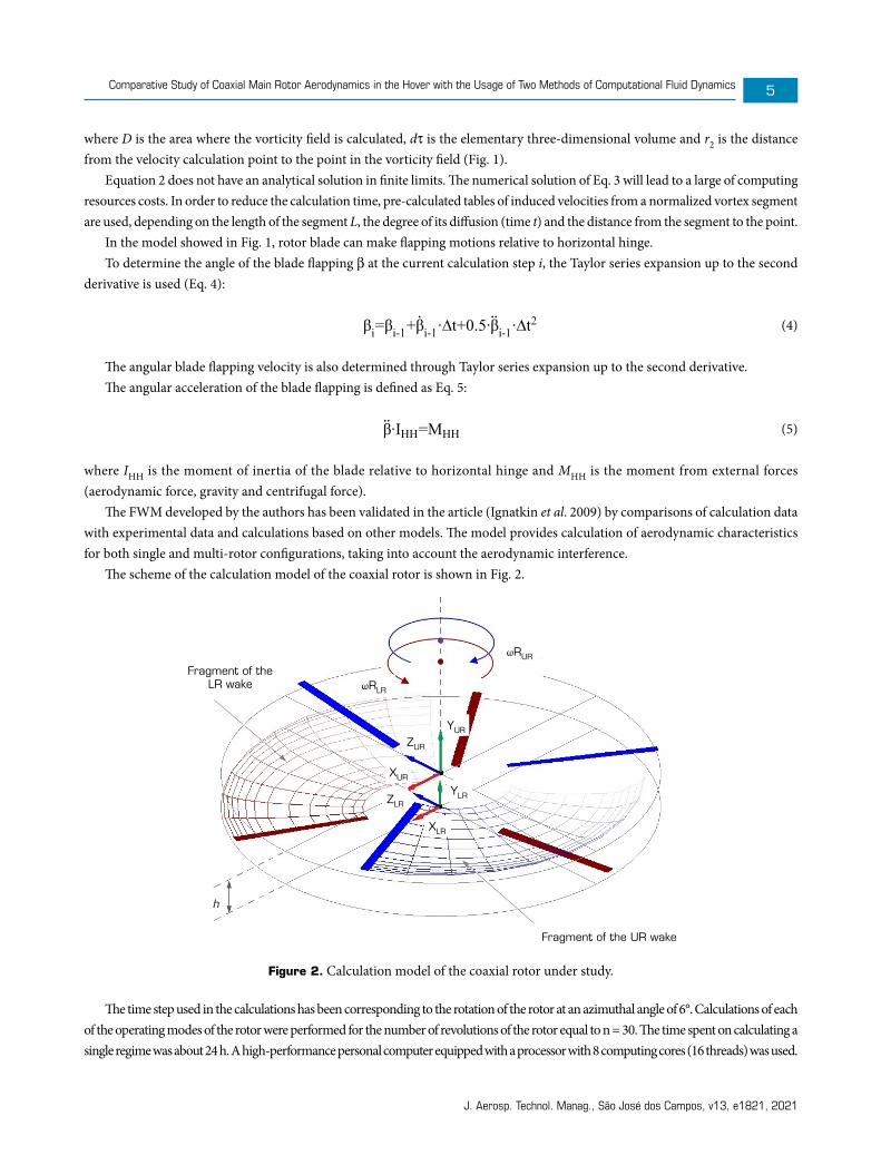
The scheme of the calculation model of the coaxial rotor is shown in Fig. 2.
Fragment of the LR wake
Fragment of the UR wake
h
ωRLR
ZUR
ZLR
XUR
XLR
YUR
YLR
ωRUR
Figure 2. Calculation model of the coaxial rotor under study.
The time step used in the calculations has been corresponding to the rotation of the rotor at an azimuthal angle of 6°. Calculations of each of the operating modes of the rotor were performed for the number of revolutions of the rotor equal to n = 30. The time spent on calculating a single regime was about 24 h. A high-performance personal computer equipped with a processor with 8 computing cores (16 threads) was used.
J. Aerosp. Technol. Manag., São José dos Campos, v13, e1821, 2021
Konstantinov SG, Ignatkin YM, Makeev PV, Nikitin SO6
UNSTEADY REYNOLDS-AVERAGED NAVIER–STOKES METHOD
Numerical modeling based on the FVM was performed in the Ansys Fluent software. In the calculations, the blades were modeled with a rigid mounting to the rotor hub. The blade cone angles for each rotor thrust values were obtained on the basis of an FWM.
The URANS equations with the k-w SST turbulence model (Menter 1993) were used for creating a viscous turbulent flow of compressible gas.
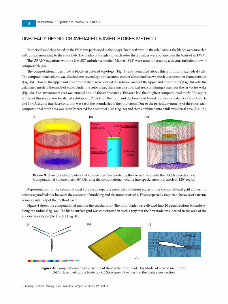
The computational mesh had a block-structured topology (Fig. 3) and contained about thirty million hexahedral cells. The computational volume was divided into several cylindrical areas, each of which had its own mesh discretization characteristics (Fig. 3b). Close to the upper and lower rotors there were located the rotation areas of the upper and lower rotors (Fig. 3b) with the calculated mesh of the smallest scale. Under the rotor areas, there was a cylindrical area containing a mesh for the far vortex wake (Fig. 3b). The environment area was situated around these three areas. This area had the roughest computational mesh. The upper border of this region was located at a distance of 2.5 R from the rotor and the lower and lateral border at a distance of 4 R (Figs. 3a and 3b). A sliding interface condition was set at the boundaries of the rotor areas. Due to the periodic symmetry of the rotor, each computational mesh area was initially created for a sector of 120° (Fig. 3с) and then combined into a full cylindrical area (Fig. 3b).
Upper rotor area
(a) (b) (c)
Lower rotor area
External area
Rotor wake area
Figure 3. Structure of computational volume mesh for modeling the coaxial rotor with the URANS method. (a) Computational volume mesh; (b) Dividing the computational volume into special areas; (c) mesh of 120° sector.
Representation of the computational volume as separate areas with different scales of the computational grid allowed to achieve a good balance between the accuracy of modeling and the number of cells. This is especially important because of extreme resource intensity of the method used.
Figure 4 shows the computational mesh of the coaxial rotor. The rotor blades were divided into 20 equal sections (chambers) along the radius (Fig. 4a). The blade surface grid was constructed in such a way that the first node was located in the area of the viscous velocity profile Y + ≤ 1 (Fig. 4b).
r/R=0.3
(a) (b) (c)
Figure 4. Computational mesh structure of the coaxial rotor blade. (a) Model of coaxial main rotor; (b) Surface mesh at the blade tip; (c) Structure of the mesh in the blade cross section.
J. Aerosp. Technol. Manag., São José dos Campos, v13, e1821, 2021
Comparative Study of Coaxial Main Rotor Aerodynamics in the Hover with the Usage of Two Methods of Computational Fluid Dynamics 7
Numerical simulation of the rotor was carried out in an unsteady setting: taking into account changes in the flow parameters over time. The initial turbulence parameters were selected based on the conditions of the average intensity of the developed turbulent flow. The relative turbulent viscosity was assumed µt/µ = 5. The value of the turbulent intensity was assumed 1%.
Preliminary test calculations were performed to study the mesh convergence. There were some meshes used with a different number of cells created by sequential, reducing the size of cells and increasing their number. The results of test calculations showed that the final mesh used in this work is sufficient for reliable calculation of aerodynamic characteristics of the coaxial main rotor under study.
The calculation of one mode for the number of revolutions of the rotor n = 25 took about 120 h with powerful supercomputer cluster.
RESULTS AND DISCUSSION
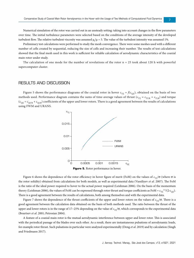
Figure 5 shows the performance diagrams of the coaxial rotor in hover сТΣ = f(сQΣ), obtained on the basis of two methods used. Performance diagram contains the sums of time-average values of thrust (сТΣ = сТUR + сТLR) and torque (сQΣ = сQUR + сQLR) coefficients of the upper and lower rotors. There is a good agreement between the results of calculations using FWM and URANS.
cT∑
0.015
0.01
0.005
0
FWM
URANS
0 0.0005 0.001 0.0015 cQ∑
Figure 5. Rotor performance in hover.
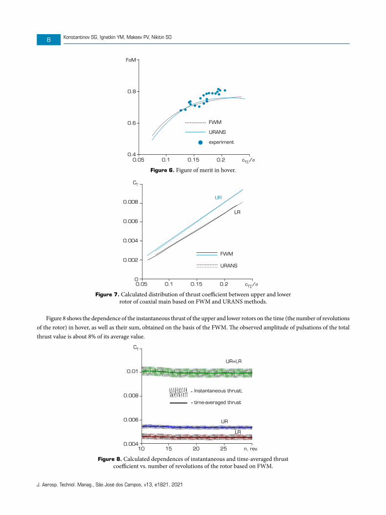
Figure 6 shows the dependence of the rotor efficiency in hover figure of merit (FoM) on the values of сТΣ/σ (where σ is the rotor solidity) obtained from calculations for both models, as well as experimental data (Vassiliyev et al. 2007). The FoM is the ratio of the ideal power required to hover to the actual power required (Leishman 2006). On the basis of the momentum theory (Leishman 2006), the values of FoM can be expressed through rotor thrust and torque coefficients as FoM = сТΣ
3/2/(2·сQΣ). There is a good agreement between the results of calculations, both among themselves and with the experimental data.
Figure 7 shows the dependence of the thrust coefficients of the upper and lower rotors on the values of сТΣ/σ. There is a good agreement between the calculation data obtained on the basis of both methods used. The ratio between the thrust of the upper and lower rotors is in the range of 17−25% depending on the value of сТΣ/σ, which corresponds to the experimental data (Bourtsev et al. 2001; Petrosian 2004).
A feature of a coaxial main rotor is the mutual aerodynamic interference between upper and lower rotor. This is associated with the periodical passage of the blades over each other. As a result, there are instantaneous pulsations of aerodynamic loads, for example rotor thrust. Such pulsations in particular were analyzed experimentally (Deng et al. 2019) and by calculation (Singh and Friedmann 2017).
J. Aerosp. Technol. Manag., São José dos Campos, v13, e1821, 2021
Konstantinov SG, Ignatkin YM, Makeev PV, Nikitin SO8
FoM
0.8
0.6
0.4
FWM
URANS
experiment
0.05 0.1 0.15 0.2 cT∑/σ
Figure 6. Figure of merit in hover.
CT
0.008
0.006
0.004
0.002
0
FWM
URANS
UR
LR
0.05 0.1 0.15 0.2 cT∑/σ
Figure 7. Calculated distribution of thrust coefficient between upper and lower rotor of coaxial main based on FWM and URANS methods.
Figure 8 shows the dependence of the instantaneous thrust of the upper and lower rotors on the time (the number of revolutions of the rotor) in hover, as well as their sum, obtained on the basis of the FWM. The observed amplitude of pulsations of the total thrust value is about 8% of its average value.
CT
0.01
0.008
0.006
0.004
Instantaneous thrust;
time-averaged thrust
UR
UR+LR
LR
10 15 20 25 n, rev.
Figure 8. Calculated dependences of instantaneous and time-averaged thrust coefficient vs. number of revolutions of the rotor based on FWM.
J. Aerosp. Technol. Manag., São José dos Campos, v13, e1821, 2021
Comparative Study of Coaxial Main Rotor Aerodynamics in the Hover with the Usage of Two Methods of Computational Fluid Dynamics 9
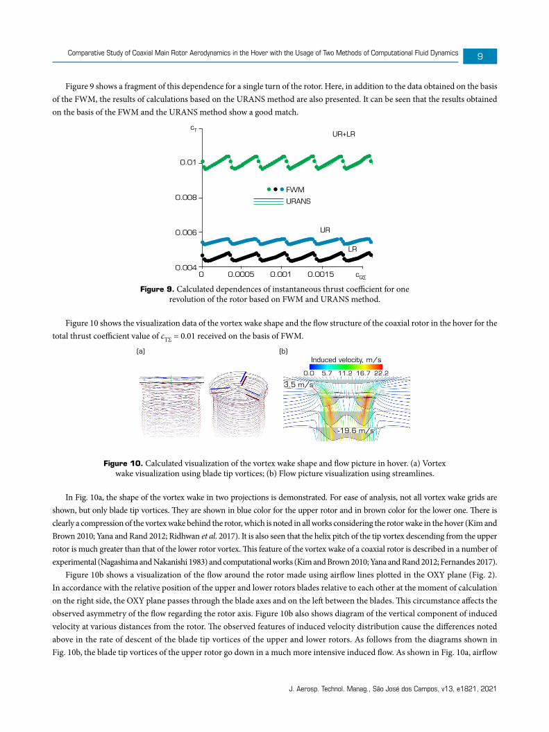
Figure 9 shows a fragment of this dependence for a single turn of the rotor. Here, in addition to the data obtained on the basis of the FWM, the results of calculations based on the URANS method are also presented. It can be seen that the results obtained on the basis of the FWM and the URANS method show a good match.
cT
0.01
0.008
0.006
0.004
FWM
URANS
UR+LR
UR
LR
0 0.0005 0.001 0.0015 cQ∑
Figure 9. Calculated dependences of instantaneous thrust coefficient for one revolution of the rotor based on FWM and URANS method.
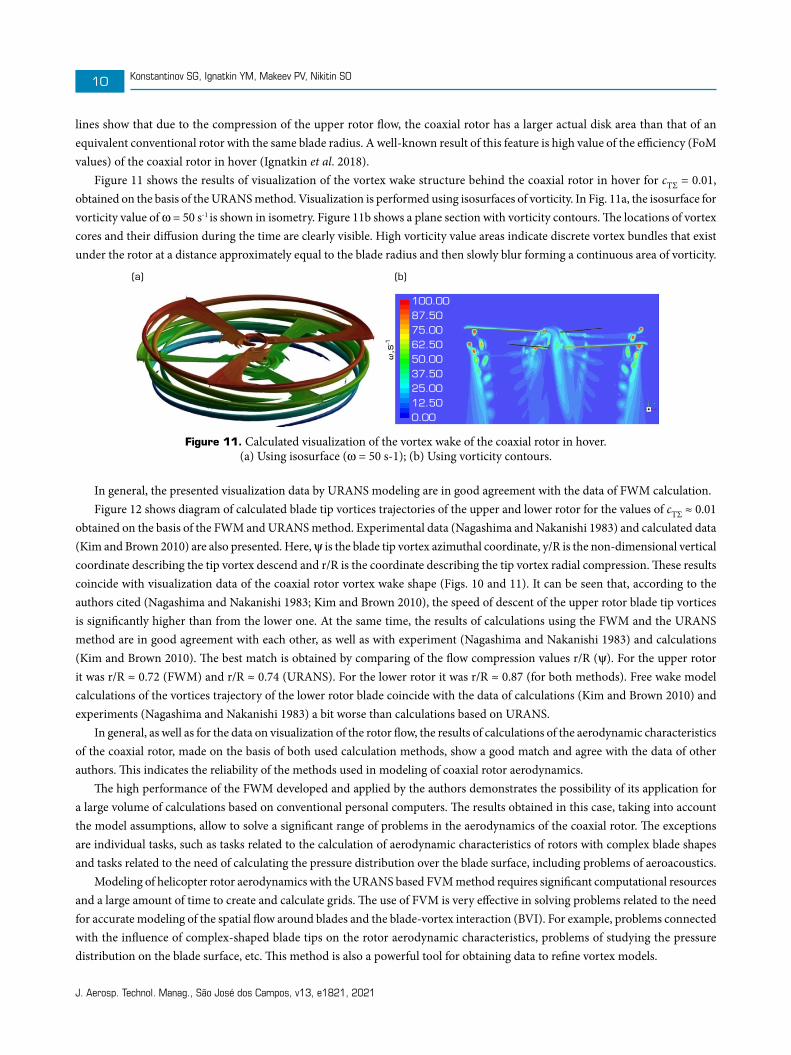
Figure 10 shows the visualization data of the vortex wake shape and the flow structure of the coaxial rotor in the hover for the total thrust coefficient value of сТΣ = 0.01 received on the basis of FWM.
Induced velocity, m/s(a) (b)
3.5 m/s
-19.6 m/s
0.0 5.7 11.2 16.7 22.2
Figure 10. Calculated visualization of the vortex wake shape and flow picture in hover. (a) Vortex wake visualization using blade tip vortices; (b) Flow picture visualization using streamlines.
In Fig. 10a, the shape of the vortex wake in two projections is demonstrated. For ease of analysis, not all vortex wake grids are shown, but only blade tip vortices. They are shown in blue color for the upper rotor and in brown color for the lower one. There is clearly a compression of the vortex wake behind the rotor, which is noted in all works considering the rotor wake in the hover (Kim and Brown 2010; Yana and Rand 2012; Ridhwan et al. 2017). It is also seen that the helix pitch of the tip vortex descending from the upper rotor is much greater than that of the lower rotor vortex. This feature of the vortex wake of a coaxial rotor is described in a number of experimental (Nagashima and Nakanishi 1983) and computational works (Kim and Brown 2010; Yana and Rand 2012; Fernandes 2017).
Figure 10b shows a visualization of the flow around the rotor made using airflow lines plotted in the OXY plane (Fig. 2). In accordance with the relative position of the upper and lower rotors blades relative to each other at the moment of calculation on the right side, the OXY plane passes through the blade axes and on the left between the blades. This circumstance affects the observed asymmetry of the flow regarding the rotor axis. Figure 10b also shows diagram of the vertical component of induced velocity at various distances from the rotor. The observed features of induced velocity distribution cause the differences noted above in the rate of descent of the blade tip vortices of the upper and lower rotors. As follows from the diagrams shown in Fig. 10b, the blade tip vortices of the upper rotor go down in a much more intensive induced flow. As shown in Fig. 10a, airflow
J. Aerosp. Technol. Manag., São José dos Campos, v13, e1821, 2021
Konstantinov SG, Ignatkin YM, Makeev PV, Nikitin SO10
lines show that due to the compression of the upper rotor flow, the coaxial rotor has a larger actual disk area than that of an equivalent conventional rotor with the same blade radius. A well-known result of this feature is high value of the efficiency (FoM values) of the coaxial rotor in hover (Ignatkin et al. 2018).
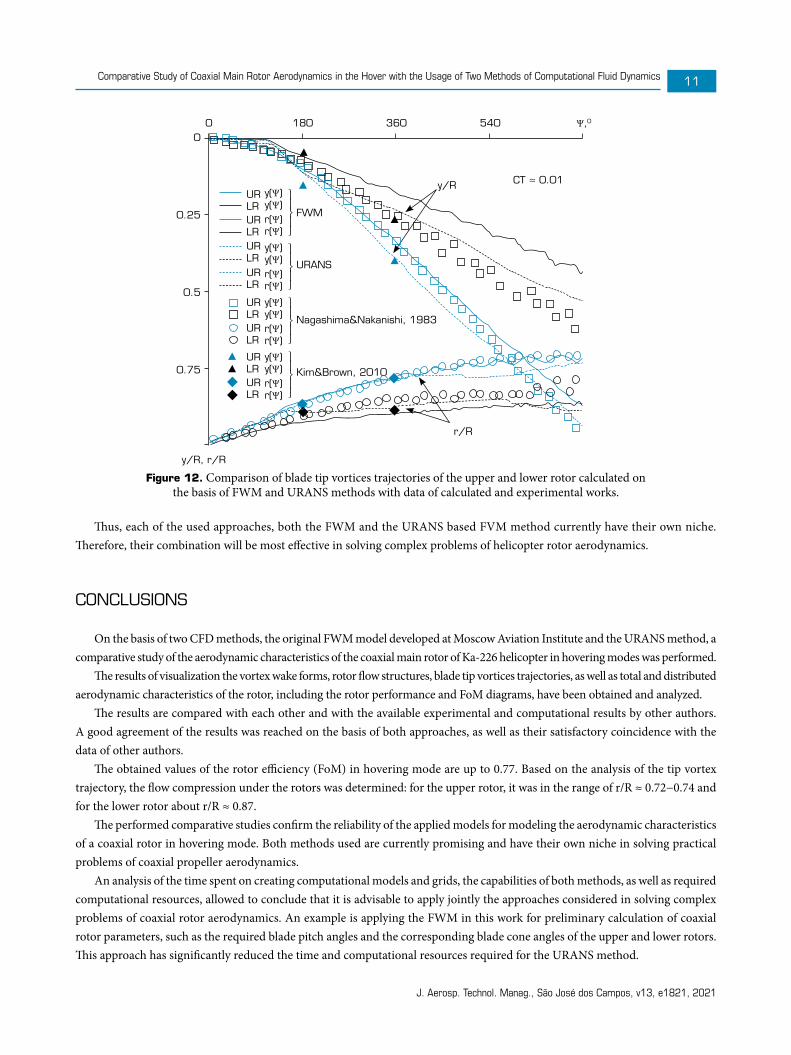
Figure 11 shows the results of visualization of the vortex wake structure behind the coaxial rotor in hover for сТΣ = 0.01, obtained on the basis of the URANS method. Visualization is performed using isosurfaces of vorticity. In Fig. 11a, the isosurface for vorticity value of ω = 50 s-1 is shown in isometry. Figure 11b shows a plane section with vorticity contours. The locations of vortex cores and their diffusion during the time are clearly visible. High vorticity value areas indicate discrete vortex bundles that exist under the rotor at a distance approximately equal to the blade radius and then slowly blur forming a continuous area of vorticity.
ω,s-
1
100.0087.5075.0062.5050.0037.5025.0012.500.00
(a) (b)
Figure 11. Calculated visualization of the vortex wake of the coaxial rotor in hover. (a) Using isosurface (ω = 50 s-1); (b) Using vorticity contours.
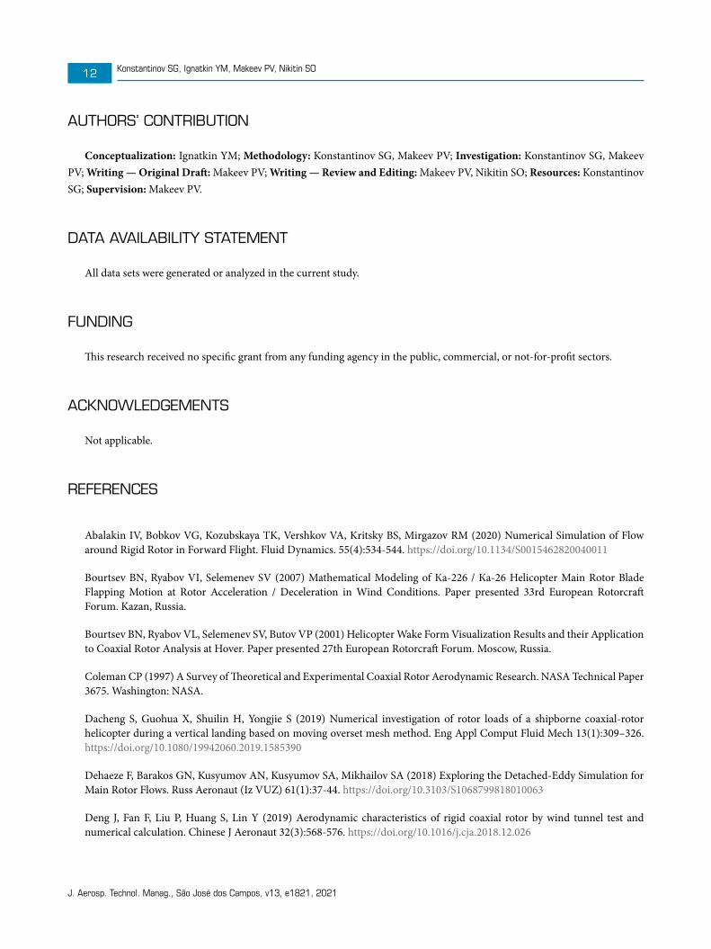
In general, the presented visualization data by URANS modeling are in good agreement with the data of FWM calculation.Figure 12 shows diagram of calculated blade tip vortices trajectories of the upper and lower rotor for the values of сТΣ ≈ 0.01
obtained on the basis of the FWM and URANS method. Experimental data (Nagashima and Nakanishi 1983) and calculated data (Kim and Brown 2010) are also presented. Here, ψ is the blade tip vortex azimuthal coordinate, y/R is the non-dimensional vertical coordinate describing the tip vortex descend and r/R is the coordinate describing the tip vortex radial compression. These results coincide with visualization data of the coaxial rotor vortex wake shape (Figs. 10 and 11). It can be seen that, according to the authors cited (Nagashima and Nakanishi 1983; Kim and Brown 2010), the speed of descent of the upper rotor blade tip vortices is significantly higher than from the lower one. At the same time, the results of calculations using the FWM and the URANS method are in good agreement with each other, as well as with experiment (Nagashima and Nakanishi 1983) and calculations (Kim and Brown 2010). The best match is obtained by comparing of the flow compression values r/R (ψ). For the upper rotor it was r/R ≈ 0.72 (FWM) and r/R ≈ 0.74 (URANS). For the lower rotor it was r/R ≈ 0.87 (for both methods). Free wake model calculations of the vortices trajectory of the lower rotor blade coincide with the data of calculations (Kim and Brown 2010) and experiments (Nagashima and Nakanishi 1983) a bit worse than calculations based on URANS.
In general, as well as for the data on visualization of the rotor flow, the results of calculations of the aerodynamic characteristics of the coaxial rotor, made on the basis of both used calculation methods, show a good match and agree with the data of other authors. This indicates the reliability of the methods used in modeling of coaxial rotor aerodynamics.
The high performance of the FWM developed and applied by the authors demonstrates the possibility of its application for a large volume of calculations based on conventional personal computers. The results obtained in this case, taking into account the model assumptions, allow to solve a significant range of problems in the aerodynamics of the coaxial rotor. The exceptions are individual tasks, such as tasks related to the calculation of aerodynamic characteristics of rotors with complex blade shapes and tasks related to the need of calculating the pressure distribution over the blade surface, including problems of aeroacoustics.
Modeling of helicopter rotor aerodynamics with the URANS based FVM method requires significant computational resources and a large amount of time to create and calculate grids. The use of FVM is very effective in solving problems related to the need for accurate modeling of the spatial flow around blades and the blade-vortex interaction (BVI). For example, problems connected with the influence of complex-shaped blade tips on the rotor aerodynamic characteristics, problems of studying the pressure distribution on the blade surface, etc. This method is also a powerful tool for obtaining data to refine vortex models.
J. Aerosp. Technol. Manag., São José dos Campos, v13, e1821, 2021
Comparative Study of Coaxial Main Rotor Aerodynamics in the Hover with the Usage of Two Methods of Computational Fluid Dynamics 11
0
0.25
0.5
0.75
y/R, r/R
y/RURLR
y(Ψ)y(Ψ)
⎫⎪⎬⎪⎭
⎫⎪⎬⎪⎭
⎫⎪⎬⎪⎭
⎫⎪⎬⎪⎭
y(Ψ)y(Ψ)
y(Ψ)y(Ψ)
y(Ψ)y(Ψ)
r(Ψ)r(Ψ)
r(Ψ)r(Ψ)
r(Ψ)r(Ψ)
r(Ψ)r(Ψ)
URLR
URLR
URLR
URLR
URLR
URLR
URLR
CT ≈ 0.01
FWM
URANS
Nagashima&Nakanishi, 1983
Kim&Brown, 2010
r/R
0 180 360 540 Ψ,0
Figure 12. Comparison of blade tip vortices trajectories of the upper and lower rotor calculated on the basis of FWM and URANS methods with data of calculated and experimental works.
Thus, each of the used approaches, both the FWM and the URANS based FVM method currently have their own niche. Therefore, their combination will be most effective in solving complex problems of helicopter rotor aerodynamics.
CONCLUSIONS
On the basis of two CFD methods, the original FWM model developed at Moscow Aviation Institute and the URANS method, a comparative study of the aerodynamic characteristics of the coaxial main rotor of Ka-226 helicopter in hovering modes was performed.
The results of visualization the vortex wake forms, rotor flow structures, blade tip vortices trajectories, as well as total and distributed aerodynamic characteristics of the rotor, including the rotor performance and FoM diagrams, have been obtained and analyzed.
The results are compared with each other and with the available experimental and computational results by other authors. A good agreement of the results was reached on the basis of both approaches, as well as their satisfactory coincidence with the data of other authors.
The obtained values of the rotor efficiency (FoM) in hovering mode are up to 0.77. Based on the analysis of the tip vortex trajectory, the flow compression under the rotors was determined: for the upper rotor, it was in the range of r/R ≈ 0.72−0.74 and for the lower rotor about r/R ≈ 0.87.
The performed comparative studies confirm the reliability of the applied models for modeling the aerodynamic characteristics of a coaxial rotor in hovering mode. Both methods used are currently promising and have their own niche in solving practical problems of coaxial propeller aerodynamics.
An analysis of the time spent on creating computational models and grids, the capabilities of both methods, as well as required computational resources, allowed to conclude that it is advisable to apply jointly the approaches considered in solving complex problems of coaxial rotor aerodynamics. An example is applying the FWM in this work for preliminary calculation of coaxial rotor parameters, such as the required blade pitch angles and the corresponding blade cone angles of the upper and lower rotors. This approach has significantly reduced the time and computational resources required for the URANS method.
J. Aerosp. Technol. Manag., São José dos Campos, v13, e1821, 2021
Konstantinov SG, Ignatkin YM, Makeev PV, Nikitin SO12
AUTHORS’ CONTRIBUTION
Conceptualization: Ignatkin YM; Methodology: Konstantinov SG, Makeev PV; Investigation: Konstantinov SG, Makeev PV; Writing — Original Draft: Makeev PV; Writing — Review and Editing: Makeev PV, Nikitin SO; Resources: Konstantinov SG; Supervision: Makeev PV.
DATA AVAILABILITY STATEMENT
All data sets were generated or analyzed in the current study.
FUNDING
This research received no specific grant from any funding agency in the public, commercial, or not-for-profit sectors.
ACKNOWLEDGEMENTS
Not applicable.
REFERENCES
Abalakin IV, Bobkov VG, Kozubskaya TK, Vershkov VA, Kritsky BS, Mirgazov RM (2020) Numerical Simulation of Flow around Rigid Rotor in Forward Flight. Fluid Dynamics. 55(4):534-544. https://doi.org/10.1134/S0015462820040011
Bourtsev BN, Ryabov VI, Selemenev SV (2007) Mathematical Modeling of Кa-226 / Кa-26 Helicopter Main Rotor Blade Flapping Motion at Rotor Acceleration / Deceleration in Wind Conditions. Paper presented 33rd European Rotorcraft Forum. Kazan, Russia.
Bourtsev BN, Ryabov VL, Selemenev SV, Butov VP (2001) Helicopter Wake Form Visualization Results and their Application to Coaxial Rotor Analysis at Hover. Paper presented 27th European Rotorcraft Forum. Moscow, Russia.
Coleman CP (1997) A Survey of Theoretical and Experimental Coaxial Rotor Aerodynamic Research. NASA Technical Paper 3675. Washington: NASA.
Dacheng S, Guohua X, Shuilin H, Yongjie S (2019) Numerical investigation of rotor loads of a shipborne coaxial-rotor helicopter during a vertical landing based on moving overset mesh method. Eng Appl Comput Fluid Mech 13(1):309–326. https://doi.org/10.1080/19942060.2019.1585390
Dehaeze F, Barakos GN, Kusyumov AN, Kusyumov SA, Mikhailov SA (2018) Exploring the Detached-Eddy Simulation for Main Rotor Flows. Russ Aeronaut (Iz VUZ) 61(1):37-44. https://doi.org/10.3103/S1068799818010063
Deng J, Fan F, Liu P, Huang S, Lin Y (2019) Aerodynamic characteristics of rigid coaxial rotor by wind tunnel test and numerical calculation. Chinese J Aeronaut 32(3):568-576. https://doi.org/10.1016/j.cja.2018.12.026
J. Aerosp. Technol. Manag., São José dos Campos, v13, e1821, 2021
Comparative Study of Coaxial Main Rotor Aerodynamics in the Hover with the Usage of Two Methods of Computational Fluid Dynamics 13
Fernandes SD (2017) Performance Analysis of a Coaxial Helicopter in Hover and Forward Flight (Master thesis). Daytona Beach: Embry-Riddle Aeronautical University. In English. [accessed Feb 03 2021] https://commons.erau.edu/cgi/viewcontent.cgi?article=1325&context=edt
Ferziger JH. (2000) Direct and Large Eddy Simulation of Turbulence. Trans Jpn Soc Mech Eng B 66(651):2754-2763. https://doi.org/10.1299/kikaib.66.651_2754
Garipova LI, Batrakov AS, Kusyumov AN, Mikhailov SA, Barakos GN (2014) Estimates of hover aerodynamics performance of rotor model. Russ Aeronaut (Iz VUZ) 57(3):223-231. https://doi.org/10.1299/kikaib.66.651_2754
Harrington RD (1951) Full-scale-tunnel investigation of the static-thrust performance of a coaxial helicopter rotor. Technical note 2318. Washington: NACA.
Ignatkin Y, Makeev P, Shomov A (2018) Calculated Research of Influence of Helicopter Main Rotors Geometry on the Efficiency in Hover Mode Based on the Nonlinear Vortex Model. Civil Aviation High Technologies 21(6):43-53. https://doi.org/10.26467/2079-0619-2018-21-6-43-53
Ignatkin YM, Konstantinov SG (2012) Investigation of the aerodynamic characteristics of the rotor of a helicopter by CFD. Trudy MAI 57(1):1-22. [accessed Feb 03 2021]. http://trudymai.ru/eng/published.php?ID=30875
Ignatkin YM, Makeev PV, Grevtsov BS, Shomov AI (2009) Nonlinear blade vortex theory of a propeller and its applications for calculating the aerodynamic characteristics of rotor and tail rotors of a helicopter. Aerospace MAI journal 16(5):24-31. [accessed Feb. 03 2021]. http://vestnikmai.ru/eng/publications.php?ID=12351
Kim HW, Brown RE (2010) A Comparison of Coaxial and Conventional Rotor Performance. J Am Helicopter Soc 55(1):12004. https://doi.org/10.4050/JAHS.55.012004
Kinzel MP, Cornelius JK, Schmitz S, Palacios JL, Langelaan JW, Adams D, Lorenz R (2019) An Investigation of the Behavior of a Coaxial Rotor in Descent and Ground Effect. Paper presented AIAA Scitech 2019 Forum. AIAA; San Diego, California, United States. https://doi.org/10.2514/6.2019-1098
Kritsky BS, Mirgazov RM, Anikin VA, Gerasimov OV (2020) Thrust pulsation of coaxial main rotor, caused by the blades relative position. Civil Aviation High Technologies 23(4):96-104. https://doi.org/10.26467/2079-0619-2020-23-4-96-104
Leishman JG (2006) Principles of Helicopter Aerodynamics. Cambridge: Cambridge University Press.
Menter FR (1993) Zonal Two Equation k-ω Turbulence Models for Aerodynamic Flows. Paper presented 24th Fluid Dynamics Conference. AIAA; Orlando, Florida, United States. https://doi.org/10.2514/6.1993-2906
Moin P, Mahesh K (1998) Direct Numerical Simulation: A Tool in Turbulence Research. Annu Rev Fluid Mech 30:539-578. https://doi.org/10.1146/annurev.fluid.30.1.539
Nagashima T, Nakanishi K (1983) Optimum performance and wake geometry of a co-axial rotor in hover. Vertica 7(3):225-239.
Petrosian EА (2004) Aerodynamics of Coaxial Helicopter. Moscow: Poligon-Press.
Ridhwan NA, Mohd N, Barakos G (2017) Performance and Wake Analysis of Rotors in Axial Flight Using Computational Fluid Dynamics. J Aerosp Technol Manag 9(2):193-202.
Singh P, Friedmann PP (2017) Application of Vortex Methods to Coaxial Rotor Wake and Load Calculations in Hover. 55th AIAA Aerospace Sciences Meeting. AIAA; Grapevine, Texas, United States. https://doi.org/10.2514/6.2017-0051
Spalart P, Allmaras S (1992) A One-Equation Turbulence Model for Aerodynamic Flows. Paper presented 30th AIAA Aerospace Sciences Meeting and Exhibit. AIAA; Reno, Nevada, United States. https://doi.org/10.2514/6.1992-439
J. Aerosp. Technol. Manag., São José dos Campos, v13, e1821, 2021
Konstantinov SG, Ignatkin YM, Makeev PV, Nikitin SO14
Strelets M (2001) Detached Eddy Simulation of Massively Separated Flows. Paper presented 39th AIAA Aerospace Sciences Meeting and Exhibit. AIAA; Reno, Nevada, United States. https://doi.org/10.2514/6.2001-879
Tan J, Sun Y, Barakos Gn (2018) Unsteady loads for coaxial rotors in forward flight computed using a vortex particle method. Aeronaut. J 122(1251):693-714. https://doi.org/10.1017/aer.2018.8
Vassiliyev BA, Kvokov VN, Pavlidi FN, Petrosian EA, Feofilov EB (2007) The Кa-226 Helicopter Flight Performance and Its Compliance with the Modern Requirements. Paper presented 33rd European Rotorcraft Forum. Curran Associates; Kazan, Russia.
Wilcox DC (1994) Turbulence Modeling for CFD. La Canada: DCW Industries Inc.
Yana J, Rand O (2012) Performance Analysis of a Coaxial Rotor System in Hover: Three Points of View. Paper presented 28th International Congress of Aeronautical Sciences. ICAS; Brisbane, Australia.