comparative characterization of both alumina and mullite
TRANSCRIPT
IOSR Journal of Engineering (IOSRJEN) www.iosrjen.org ISSN (e): 2250-3021, ISSN (p): 2278-8719 Vol. 08, Issue 5 (May. 2018), ||VII|| PP 08-20
International organization of Scientific Research 8 | P a g e
Comparative Characterization of both Alumina and Mullite Matrix Composites Manufactured Combining Filament Winding
and Freeze Gelation Processes
Thays Machry1*; Christian Wilhelmi2; Prof. Hazim Ali Al-Qureshi3; Prof. Carlos Perez Bergmann4 1Airbus SAS, Hamburg, Germany
2 Airbus Defense and Space, Friedrichshafen, Germany 3 Federal University of Santa Catarina (UFSC), Florianópolis, Brazil
4Federal University of Rio Grande do Sul (UFRGS), Porto Alegre, Brazil Corresponding Auther: Thays Machry
Abstract: Filament winding and freeze gelation technique are combined in this work to manufacture all-oxide ceramic matrix composites with different matrices.Alumina and mullite are used in combination with a silica sol to manufacture two ceramic suspensions. Fiber infiltration and lay-up is conducted with NextelTM 610 fiber with 3000 denier(organic sized)using the filament winding process. After lay-up the composite is submitted to subzero temperatures forcing the consolidation of the ceramic matrix. The combination of these processing routes is successfully implemented to build up cost-efficient composites.Homogeneous impregnation of the fiber with both ceramic suspensions is achieved. Use of different ceramic fillers influenced, however,porosity formation in the material and consequently its mechanical performance. Interlaminar shear and bending strength of composites with mullite filler are lower than the strength of composites using alumina as filler. Keywords: Composites, Al2O3, Mullite, Sol–gel processes --------------------------------------------------------------------------------------------------------------------------------------- Date of Submission: 25-04-2018 Date of acceptance: 14-05-2018 ---------------------------------------------------------------------------------------------------------------------------------------
I. INTRODUCTION Fiber reinforced ceramic matrix composites (CMC) started being significantly studied in the early
1980s in order to overcome the main drawback of monolithic ceramics, their high brittleness and low fracture toughness(Cox, Zok 1996). These materials, in special oxide based CMC, provide high strength, toughness, notch insensitivity, refractoriness and environmental stability at high temperature applications such as diffusor and exhaust from aircraft engines, stationary gas turbines, thermal protection systems and radomes.
Ceramic matrix composites are interestingespecially for gas turbine hot section components because of their superior high temperature durability compared to metals, which enables higher component operating temperatures, improves fuel efficiencyand prevent the formation of CO(Roode et al. 2005). Ceramic materials have the potential to provide 30.000 hours of trouble free operation that industrial gas turbine operators expect. Additionally, the cooling air saved due to the reduced demand for hot section component cooling can be redirected to lean out the combustor primary zone and reduce the formation of NOx(Roode et al. 2005).
Several developments involving different manufacturing methods and slurry systems have been studied resulting in composites with different microstructures and properties. Regardless of the manufacturing route used,current materials havelowinterlaminar performance and often present long processing times, which reflects directly in high manufacturing costs. Additionally,some of these compositeshave a SiC phase,leaving they more susceptible to oxidation.Therefore, further developments of ceramic matrix composites using alternative manufacturing routes are still required.
In order to pursuit these requirements the combination of filament winding and freeze gelation process is chosen. Filament winding is a well-known automated technique for matrix infiltration among fiber filaments and composite lay-up, which guaranties production reproducibility and homogeneous fiber impregnation throughout the composite. Freeze gelation is a cost-efficient consolidation technique for manufacturing monolithic ceramics and beneficent once the manufacturing time and costs are relatively low.
Freeze gelation is a process based in the colloidal processing of a sol gel suspension. A colloidal suspension of solid ceramic particles (sol) is converted to a non-crystalline gel through adjustment of the small interparticle forces that control sol stability. The adjustment of the interparticle forces can take place by
Comparative Characterization of Both Alumina and Mullite Matrix Composites Manufactured ..
International organization of Scientific Research 9 | P a g e
modification of the suspension pH or change in temperature or even pressure. The gel is then dried and sintered. (Russel-Floyd et al. 1993a; Chant et al. 1995; Chant et al.; Harris et al. 1998; Hench, West 1990).
In freeze gelation, submission of the sol gel to subzero temperatures is used to induce gelation. To achieve gelation of the suspension and prevention of re-melting of the frozen ceramic during reheating, the use of a freeze sensitive sol is necessary. The majority of colloidal sols that are irreversible after freezing are silica based (Statham et al. 1998; Brinker, Scherer 1990). The silica sol is consolidated through the bonding of its particles and formation of a three-dimensional network (Peng et al. 2015). Two mechanisms can promote this consolidation: gelation or coagulation. Gelation involves the collision of two particles and the formation of siloxane bonds (Si-O-Si) and it is method used in this study (Ismael et al. 2006).
As important as the colloidal sol is the filler. Ceramic fillers with different composition and particle sizes influence directly in the suspension stabilization and viscosity, having a consequential and crucial influence in the ice crystal growth during freezing. Higher particles sizes and presence of agglomerates often work as a barrier to the growth of ice crystals modifying the path in which the ice crystals grow and, further on, the pore morphology in the ceramic matrix (Liu et al. 2016).
Advantages of sol gel methods over conventional ceramic processing routes include high matrix homogeneity and relatively low sintering temperatures as a consequence of the high reactivity from the very high surface area of the gel (Chant et al. 1995; Statham et al. 1998; Sigmund et al. 2000; Rodeghiero et al. 1998; Tari 2003).The use of freeze gelation allows the formation of low-costceramics and homogeneous distribution of the porosity throughout the material.
II. EXPERIMENTAL
2.1 Materials and Composites Manufacture The productionsteps used for the combination of filament winding with the freeze gelation
processareillustrated in Figure 1. A ceramic slurry infiltration process (CSI) is applied for the manufacture of the composites making use of the sol gel transition method.
Silica sol Nexsil 20 from the company Nyacol containing 40 wt. % of silica nanoparticles (20 nm) is used as base for suspension manufacture. Ceramic fillers used are mullite (24,2 wt. % SiO2, 75,2 wt. % Al2O3) 21113 – 10A from Reimbold & Strick and alumina (99 wt. % Al2O3) Ceralox APA-0,5 produced by Sasol. Dolapix CE64from the company Zschimmer & Schwarz GmbH is used as deflocculating agent. Dolapix is a carboxylic and has a pH of 7. The aqueous suspensions are prepared with a total solids content of 75 wt. %.
For the preparation of the sol gel suspension mechanical mixers from IKA electronics are used. The homogenization method used for the suspensions with mullite (d50=3 µm) had to be optimized for the alumina particles taking into account their smaller particle sizes (d50=0,3 µm) and higher tendency to form agglomerates. Therefore, for the alumina suspensions a mixer with higher energy (Ultra-TURRAX T25 from IKA) is used.
After the sol gel suspension isprepared, the continuous fibers are infiltrated with the sol gel matrix in the filament winding machine (shown in Figure 2a) and directly laid-up into a mold with desired geometry. The fiber used for the composites manufacture is NextelTM 610, 3000 denier, organic sizing (PVA) from 3MTM, USA. The composites are manufactured with fiber architecture of 0°/90° built in 8 symmetric layers[0/90]2S. NextelTM 610 is composed of α-Al2O3, when exposed to temperatures above 1100°C for long time periods it shows grain growth and pore formation. At this point, the larger grains tend to grow at the expense of smaller grains because of diffusion processes at grain boundaries, leading to fiber embrittlement.
After lay-up, the composite is immediately frozen in order to force sol gel transition. Freezing is conducted at -18°C for 3 hours. The sol is converted to a rigid matrix without significant shrinkage. In this step, the structure of the material is formed and the final porosity is determined once the continuous crystals of solvent are formed in the matrix.
Subsequent drying is conducted between 50°C - 60°C for 24 hours. This step results in very low bulk shrinkage below 1%, due to low capillary stresses associated with the relatively large and open porosity.Pore sizes range typically between 1 and 10μm in diameter, which results from the nucleation and growth of ice crystals during freezing (Chant et al. 1995; Deville 2008). Matrix densification is achieved during finaltwo-step sintering at temperatures up to 1150°C (Lóh et al 2016). In Figure 2b the composite manufactured with mullite filler, fiber NextelTM 610, 3000 denier, 8 layers is shown after winding, freezing and drying.
2.2 Characterization Methods Optical Microscope and Scanning Electron Microscope (SEM)
Optical microscope Polyvar SC from Leica is used for microstructure images. Samples are embedded with epoxy resin, grinded with 125 µm, 75 µm, 40 µm, and 30 µm papers and polished with 9 µm, 6 µm, 3 µm and 1 µm paste. Scanning Electron Microscope Model JSM 6320F Scanning Microscope from the company JEOL is used. Viscosity
Comparative Characterization of Both Alumina and Mullite Matrix Composites Manufactured ..
International organization of Scientific Research 10 | P a g e
The viscosity of the ceramic suspensions are measured using a Brookfield Viscometer, model LVDV-E, from Brookfield Engineering Laboratories, USA. The viscosity of the suspensions is measured with spindle number 4 throughout a velocity range of 1 to 60 RPM. Viscosity results are given in centipoises (cP). The spindle number is selected according to the size of the container in which the ceramic slurry is tested. Mercury Intrusion
Mercury intrusion technique is used to measure the open porosity, pore size, average pore diameter, cumulative volume and pore size distribution of ceramics and composites manufactured using Pascal 140 and 440 from Fisons Instruments. The pressure applied during measurement is first from 0,0001 to 4 bar, then the samples are submitted to pressures from 1 to 400 bars.
The required equilibrated pressure is inversely proportional to the size of the pores, only slight pressure being required to intrude mercury into large macropores, whereas much greater pressures are required to force mercury into small pores. Helium Pycnometer
Helium pycnometer from Micromeritics USA, model AccuPyc 1330 is used to measure density. The equipment works based on the principle of gas displacement from a pre-defined volume (chamber) by placing a solid volume in a chamber. The size of the helium atoms enables the filling of pores up to a minimum size of approximately 0,1 nm.
The main components of a Pycnometer are a sample chamber and a reference chamber with defined volumes (VPK, VREF). These chambers are connected to each other via a valve system. High sensitivity pressure sensor determines the pressure inside the chambers. For the density determination, the sample is placed into the sample chamber and sealed. After completely air evacuation, the sample chamber is filled with a defined helium gas pressure (P1). Afterwards, the connection between the chambers is opened and the total pressure (P2) is measured. From the known chamber volume and the measured gas pressures, the inserted sample volume can be calculated according to Equation 1. With the sample weight and the measured volume (VPR) the apparent density can be calculated (Glover 2012). V
Pr = VPK − VRef ×P2
P1−P2
Equation 1
Thermogravimetry (TG) and Differential Thermal Analysis (DTA)
Simultaneously Differential Thermal Analysis (DTA) and Thermogravimetry (TG) are carried out in the equipment STA503 from the company Bähr.
In DTA, the temperature of a sample is compared with an inert reference material during a programmed change of temperature. Using this technique, the temperature in which thermal events such as melting, decomposition or change in the crystal structure occurs can be recognized. If an endothermic event takes place, the temperature of the sample will lag behind that of the reference and a minimum (endothermic peak) will be observed on the curve. On the contrary, if an exothermal event takes place, then the temperature of the sample will exceed that of the reference and a maximum (exothermic peak) will be observed on the curve. TG analysis shows changes in mass of the material as a function of temperature or time under a controlled atmosphere. Mechanical Tests
Mechanical tests are conducted in a universal test machine Zwick / Roell Z005 (Zwick, Ulm, Germany) using a load cell of 5 kN, with a crosshead speed of 0,5 mm/min. Samples for mechanical characterization are prepared using a cutting machine with diamond disc.
The following interlaminar tests are conducted: compression shear, transversal tensile and short bending test. The strength in fiber direction is measured using the four-point bending test.Fracture toughness is measured with single edge notched bending test (SENB). Compression Shear Test
The compression shear test is conducted according to the standard DIN EN 658-4 (May 2003) with samples of the dimensions 27x10x3 in mm3.
During the test the sample is compressed as indicated in the arrow in Figure 3 and the sample is forced to fail in shear between two notches.The interlaminar shear strength is calculated using Equation 2 (DIN EN 658-4) in which, ILSSc is the interlaminar shear strength in plane in megapascal (MPa),F is the shear fracture force in Newton (N),b is the average sample width in millimeters (mm) and L is the distance between notches in millimeters (mm).
ILSSC =F
bL Equation 2
Comparative Characterization of Both Alumina and Mullite Matrix Composites Manufactured ..
International organization of Scientific Research 11 | P a g e
Transversal Tensile Test The transversal tensile test followed an intern standard from the Advanced Ceramics Institute at the
University of Bremen. In this test, composites samples with dimensions of 10x10x3 mm3are glued between two metal screws using cyanoacrylate glue. After the glue is cured (20 minutes at room temperature) the sample is submitted to tensile traction in transversal direction such that the matrix between composite layers is forced to fail.
The transversal tensile strength is calculated using Equation 3, in whichτ is the strength in megapascal (MPa), F is the transversal tensile force in Newton (N) andA is the average sample area in square millimeters (mm²).
τ =F
A Equation 3
Short Bending Test The interlaminar shear strength of CMC is commonly determined by the short bending test. The
samples are tested in four-point bending with a shortdistance between the supports. The stress applied in normal direction to the layers and the test specimen dimensions must be set so that interlaminar failure occurs (DIN EN 658-5).
The interlaminar shear strength (ILSSB) is calculated according to Equation 4 where F is the applied force to fracture in Newton (N), b is the average sample width in millimeters (mm) and h is the average sample thickness in millimeters (mm).
Test design with 50 mm distance between the lower support rollers and 20 mm between the upper ones is used.
ILSSb =3F
4bh Equation 4
Four-point Bending Test Four-point bending tests are conducted with 80 mm distance between the lower support rollers and 20
mm between the upper ones. To measure deflection of the sample a sensor from Solartron Metrology (Bognor Regis, UK) AX5 (±1 mm), Linear Variable Differential Transformer (LVDT), is used.
For the bending strength calculation Equations 5is used (DIN EN 658-3) in which σ is the bendingstrength in megapascal (MPa), L is the length of the support outer span in millimeters (mm), Li is the length of the support inner span in millimeters (mm), F is the fracture force in Newton (N), b is the average sample width in millimeters (mm), and d is the deflection due to the load applied in millimeters (mm).
σ =3F L − Li
2bd2 Equation 5
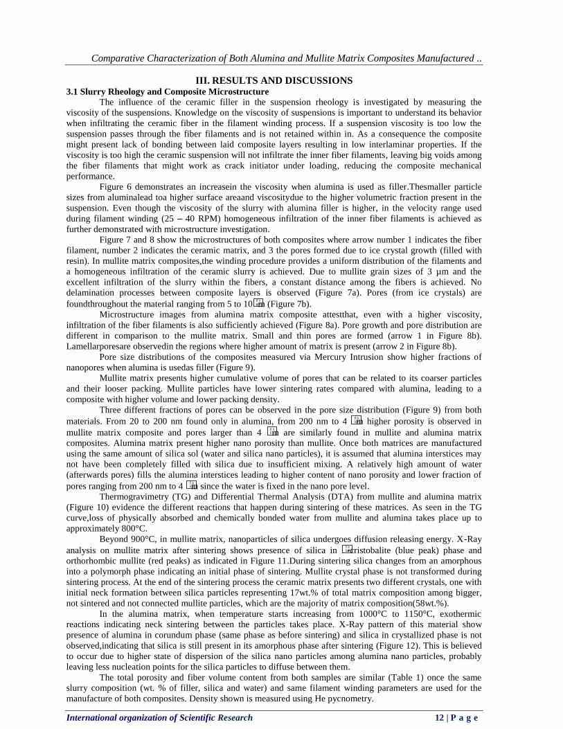
Single Edge Notched Bending (SENB) Test The single Edge Notched Bending (SENB) test is conducted according to the standard DIN EN ISO
15732 (December 2004). The test evaluates the fracture toughness of the material and KIC (plane-strainfracture toughness or critical stress intensity value) is determined. At Figure 4 a sketch of the test sample is given.
The mean value for the fracture toughness is calculated using Equation 6 (DIN EN ISO 15732). In Equation 6σ is the strength in megpascal (MPa), c is the maximum crack length admitted in meters (m), F is the fracture force in Newton (N), B is the average sample width in millimeters (mm),W is the average sample length in millimeters (mm) and is the induced crack length divided by the sample height in millimeters (mm).
KIC = σ cY =F
B W
L− l
W
3 α
2 1−α 1,5 Y Equation 6
When four point bending test is applied, Y is obtained according to Equation 7 (DIN EN ISO 15732).
Y = 1,9887 − 1,326α −3,49 −0,68α + 1,35α2) α 1 − α
1 − α 2 Equation 7
Composites Fiber Volume Content
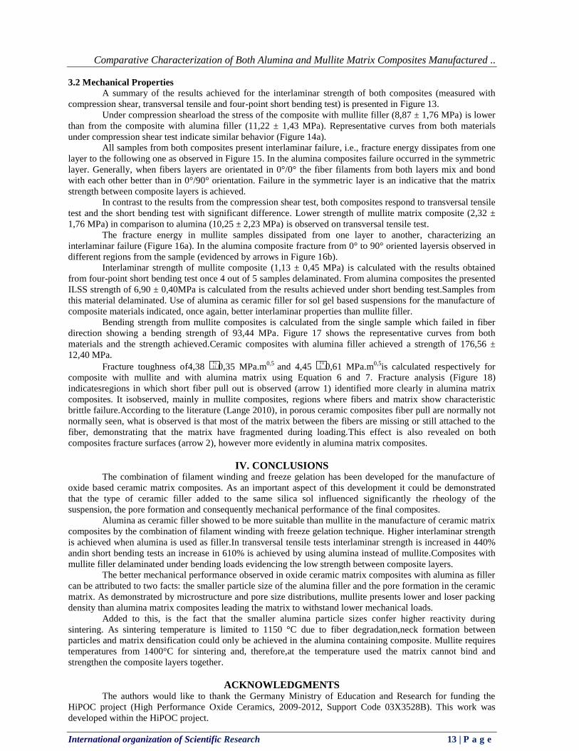
For the composite fiber volume content two image analysis programs are used: Gimp 2.4 and Image J. Since in the composite microstructure image fiber and matrix are represented in different grey scales (Figure 5a) it is necessary to identify in a binary color system what is fiber and what is matrix. Therefore, with Gimp program, the fibers are painted in black and the background in white (Figure 5b). Afterwards, the binary color image is opened in the program Image J. With this program the ratio of the black color in relation to the background is calculated. Once the black points correspond to fibers, the fiber volume percentage in the image is obtained. For each material inthis work this image analysis is made in three different places of the sample and the results presented correspond to an average
Comparative Characterization of Both Alumina and Mullite Matrix Composites Manufactured ..
International organization of Scientific Research 12 | P a g e
III. RESULTS AND DISCUSSIONS 3.1 Slurry Rheology and Composite Microstructure
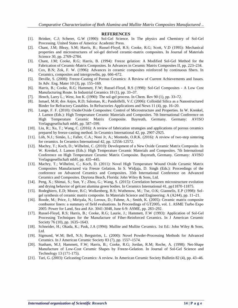
The influence of the ceramic filler in the suspension rheology is investigated by measuring the viscosity of the suspensions. Knowledge on the viscosity of suspensions is important to understand its behavior when infiltrating the ceramic fiber in the filament winding process. If a suspension viscosity is too low the suspension passes through the fiber filaments and is not retained within in. As a consequence the composite might present lack of bonding between laid composite layers resulting in low interlaminar properties. If the viscosity is too high the ceramic suspension will not infiltrate the inner fiber filaments, leaving big voids among the fiber filaments that might work as crack initiator under loading, reducing the composite mechanical performance.
Figure 6 demonstrates an increasein the viscosity when alumina is used as filler.Thesmaller particle sizes from aluminalead toa higher surface areaand viscositydue to the higher volumetric fraction present in the suspension. Even though the viscosity of the slurry with alumina filler is higher, in the velocity range used during filament winding (25 – 40 RPM) homogeneous infiltration of the inner fiber filaments is achieved as further demonstrated with microstructure investigation.
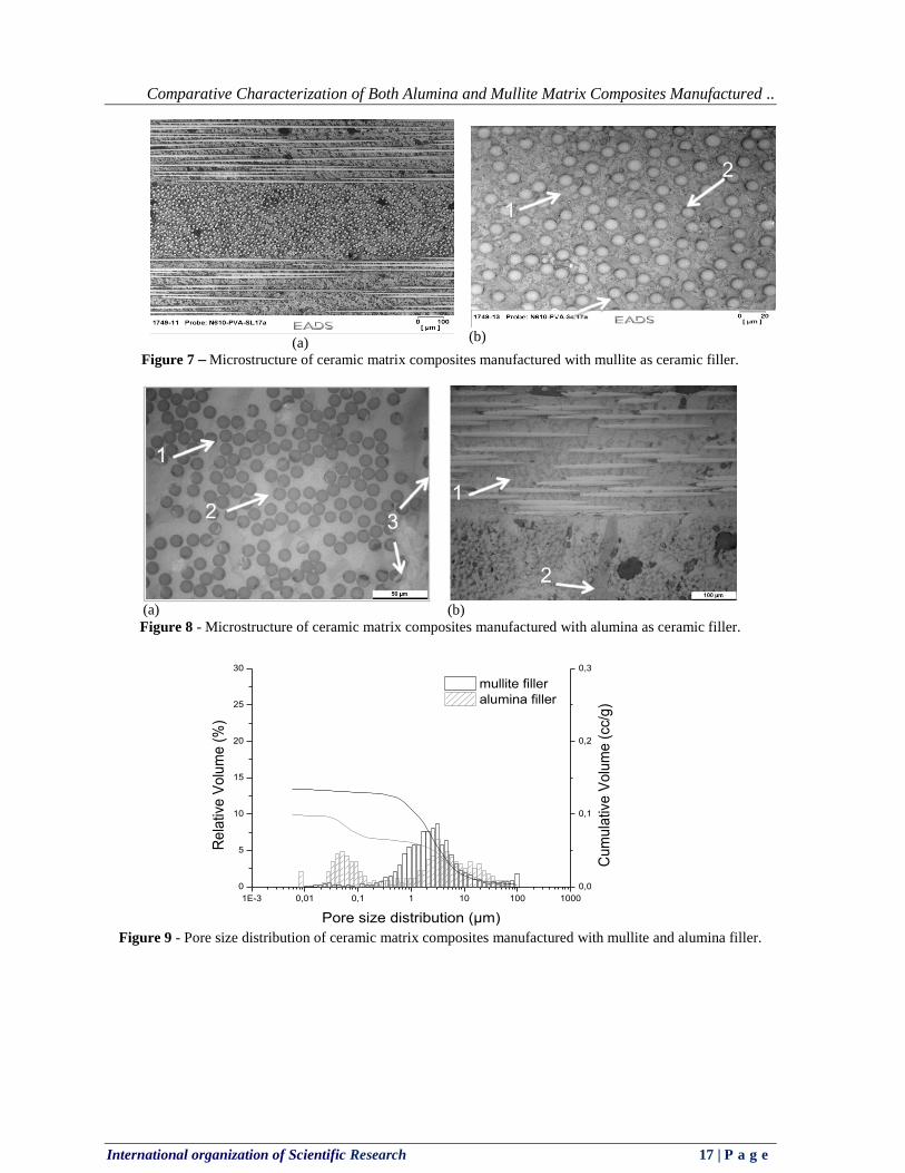
Figure 7 and 8 show the microstructures of both composites where arrow number 1 indicates the fiber filament, number 2 indicates the ceramic matrix, and 3 the pores formed due to ice crystal growth (filled with resin). In mullite matrix composites,the winding procedure provides a uniform distribution of the filaments and a homogeneous infiltration of the ceramic slurry is achieved. Due to mullite grain sizes of 3 µm and the excellent infiltration of the slurry within the fibers, a constant distance among the fibers is achieved. No delamination processes between composite layers is observed (Figure 7a). Pores (from ice crystals) are foundthroughout the material ranging from 5 to 10 m (Figure 7b).
Microstructure images from alumina matrix composite attestthat, even with a higher viscosity, infiltration of the fiber filaments is also sufficiently achieved (Figure 8a). Pore growth and pore distribution are different in comparison to the mullite matrix. Small and thin pores are formed (arrow 1 in Figure 8b). Lamellarporesare observedin the regions where higher amount of matrix is present (arrow 2 in Figure 8b).
Pore size distributions of the composites measured via Mercury Intrusion show higher fractions of nanopores when alumina is usedas filler (Figure 9).
Mullite matrix presents higher cumulative volume of pores that can be related to its coarser particles and their looser packing. Mullite particles have lower sintering rates compared with alumina, leading to a composite with higher volume and lower packing density.
Three different fractions of pores can be observed in the pore size distribution (Figure 9) from both materials. From 20 to 200 nm found only in alumina, from 200 nm to 4 m higher porosity is observed in mullite matrix composite and pores larger than 4 m are similarly found in mullite and alumina matrix composites. Alumina matrix present higher nano porosity than mullite. Once both matrices are manufactured using the same amount of silica sol (water and silica nano particles), it is assumed that alumina interstices may not have been completely filled with silica due to insufficient mixing. A relatively high amount of water (afterwards pores) fills the alumina interstices leading to higher content of nano porosity and lower fraction of pores ranging from 200 nm to 4 m since the water is fixed in the nano pore level.
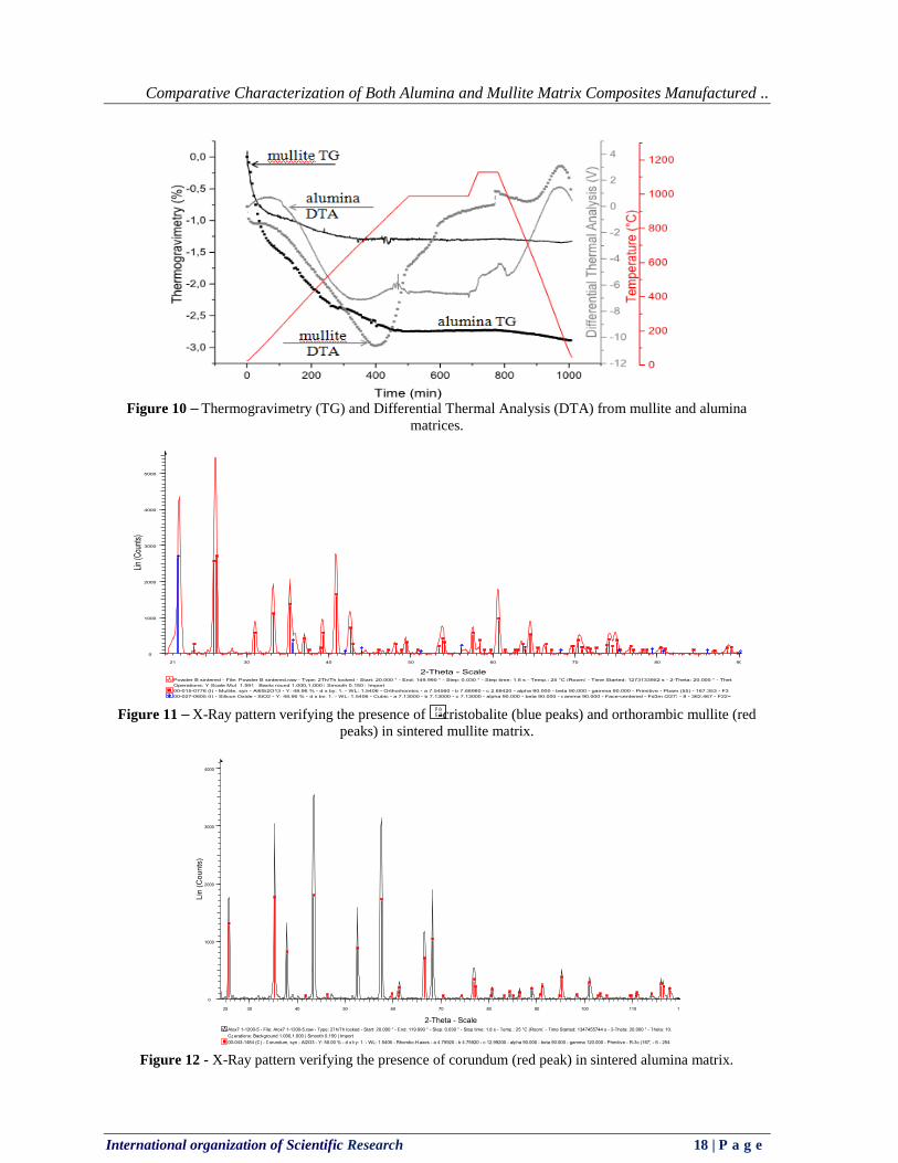
Thermogravimetry (TG) and Differential Thermal Analysis (DTA) from mullite and alumina matrix (Figure 10) evidence the different reactions that happen during sintering of these matrices. As seen in the TG curve,loss of physically absorbed and chemically bonded water from mullite and alumina takes place up to approximately 800°C.
Beyond 900°C, in mullite matrix, nanoparticles of silica undergoes diffusion releasing energy. X-Ray analysis on mullite matrix after sintering shows presence of silica in -cristobalite (blue peak) phase and orthorhombic mullite (red peaks) as indicated in Figure 11.During sintering silica changes from an amorphous into a polymorph phase indicating an initial phase of sintering. Mullite crystal phase is not transformed during sintering process. At the end of the sintering process the ceramic matrix presents two different crystals, one with initial neck formation between silica particles representing 17wt.% of total matrix composition among bigger, not sintered and not connected mullite particles, which are the majority of matrix composition(58wt.%).
In the alumina matrix, when temperature starts increasing from 1000°C to 1150°C, exothermic reactions indicating neck sintering between the particles takes place. X-Ray pattern of this material show presence of alumina in corundum phase (same phase as before sintering) and silica in crystallized phase is not observed,indicating that silica is still present in its amorphous phase after sintering (Figure 12). This is believed to occur due to higher state of dispersion of the silica nano particles among alumina nano particles, probably leaving less nucleation points for the silica particles to diffuse between them.
The total porosity and fiber volume content from both samples are similar (Table 1) once the same slurry composition (wt. % of filler, silica and water) and same filament winding parameters are used for the manufacture of both composites. Density shown is measured using He pycnometry.
Comparative Characterization of Both Alumina and Mullite Matrix Composites Manufactured ..
International organization of Scientific Research 13 | P a g e
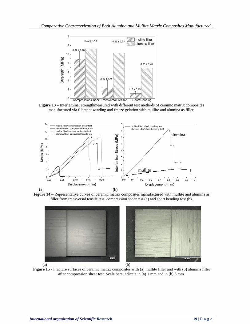
3.2 Mechanical Properties A summary of the results achieved for the interlaminar strength of both composites (measured with
compression shear, transversal tensile and four-point short bending test) is presented in Figure 13. Under compression shearload the stress of the composite with mullite filler (8,87 ± 1,76 MPa) is lower
than from the composite with alumina filler (11,22 ± 1,43 MPa). Representative curves from both materials under compression shear test indicate similar behavior (Figure 14a).
All samples from both composites present interlaminar failure, i.e., fracture energy dissipates from one layer to the following one as observed in Figure 15. In the alumina composites failure occurred in the symmetric layer. Generally, when fibers layers are orientated in 0°/0° the fiber filaments from both layers mix and bond with each other better than in 0°/90° orientation. Failure in the symmetric layer is an indicative that the matrix strength between composite layers is achieved.
In contrast to the results from the compression shear test, both composites respond to transversal tensile test and the short bending test with significant difference. Lower strength of mullite matrix composite (2,32 ± 1,76 MPa) in comparison to alumina (10,25 ± 2,23 MPa) is observed on transversal tensile test.
The fracture energy in mullite samples dissipated from one layer to another, characterizing an interlaminar failure (Figure 16a). In the alumina composite fracture from 0° to 90° oriented layersis observed in different regions from the sample (evidenced by arrows in Figure 16b).
Interlaminar strength of mullite composite (1,13 ± 0,45 MPa) is calculated with the results obtained from four-point short bending test once 4 out of 5 samples delaminated. From alumina composites the presented ILSS strength of 6,90 ± 0,40MPa is calculated from the results achieved under short bending test.Samples from this material delaminated. Use of alumina as ceramic filler for sol gel based suspensions for the manufacture of composite materials indicated, once again, better interlaminar properties than mullite filler.
Bending strength from mullite composites is calculated from the single sample which failed in fiber direction showing a bending strength of 93,44 MPa. Figure 17 shows the representative curves from both materials and the strength achieved.Ceramic composites with alumina filler achieved a strength of 176,56 ± 12,40 MPa.
Fracture toughness of4,38 0,35 MPa.m0,5 and 4,45 0,61 MPa.m0,5is calculated respectively for composite with mullite and with alumina matrix using Equation 6 and 7. Fracture analysis (Figure 18) indicatesregions in which short fiber pull out is observed (arrow 1) identified more clearly in alumina matrix composites. It isobserved, mainly in mullite composites, regions where fibers and matrix show characteristic brittle failure.According to the literature (Lange 2010), in porous ceramic composites fiber pull are normally not normally seen, what is observed is that most of the matrix between the fibers are missing or still attached to the fiber, demonstrating that the matrix have fragmented during loading.This effect is also revealed on both composites fracture surfaces (arrow 2), however more evidently in alumina matrix composites.
IV. CONCLUSIONS
The combination of filament winding and freeze gelation has been developed for the manufacture of oxide based ceramic matrix composites. As an important aspect of this development it could be demonstrated that the type of ceramic filler added to the same silica sol influenced significantly the rheology of the suspension, the pore formation and consequently mechanical performance of the final composites.
Alumina as ceramic filler showed to be more suitable than mullite in the manufacture of ceramic matrix composites by the combination of filament winding with freeze gelation technique. Higher interlaminar strength is achieved when alumina is used as filler.In transversal tensile tests interlaminar strength is increased in 440% andin short bending tests an increase in 610% is achieved by using alumina instead of mullite.Composites with mullite filler delaminated under bending loads evidencing the low strength between composite layers.
The better mechanical performance observed in oxide ceramic matrix composites with alumina as filler can be attributed to two facts: the smaller particle size of the alumina filler and the pore formation in the ceramic matrix. As demonstrated by microstructure and pore size distributions, mullite presents lower and loser packing density than alumina matrix composites leading the matrix to withstand lower mechanical loads.
Added to this, is the fact that the smaller alumina particle sizes confer higher reactivity during sintering. As sintering temperature is limited to 1150 °C due to fiber degradation,neck formation between particles and matrix densification could only be achieved in the alumina containing composite. Mullite requires temperatures from 1400°C for sintering and, therefore,at the temperature used the matrix cannot bind and strengthen the composite layers together.
ACKNOWLEDGMENTS
The authors would like to thank the Germany Ministry of Education and Research for funding the HiPOC project (High Performance Oxide Ceramics, 2009-2012, Support Code 03X3528B). This work was developed within the HiPOC project.
Comparative Characterization of Both Alumina and Mullite Matrix Composites Manufactured ..
International organization of Scientific Research 14 | P a g e
REFERENCES [1]. Brinker, C.J; Scherer, G.W (1990): Sol-Gel Science. In The physics and Chemistry of Sol-Gel
Processing. United States of America: Academic Press. [2]. Chant, J.M; Bleay, S.M; Harris, B.; Russel-Floyd, R.S; Cooke, R.G; Scott, V.D (1995): Mechanical
properties and microstructures of sol-gel derived ceramic-matrix composites. In Journal of Materials Science 30, pp. 2769–2784.
[3]. Chant, J.M; Cooke, R.G; Harris, B. (1994): Freeze gelation: A Modified Sol-Gel Method for the Fabrication of Ceramic-Matrix Composites. In Advances in Ceramic Matrix Composites II, pp. 223–234.
[4]. Cox, B.N; Zok, F. W. (1996): Advances in ceramic composites reinforced by continuous fibers. In Ceramics, composites and intergrowths, pp. 666–672.
[5]. Deville, S. (2008): Freeze-Casting of Porous Ceramics: A Review of Current Achievements and Issues. In Adv. Eng. Mater 10 (3), pp. 155–169.
[6]. Harris, B.; Cooke, R.G; Hammett, F.W; Russel-Floyd, R.S (1998): Sol-Gel Composites - A Low Cost Manufacturing Route. In Industrial Ceramics 18 (1), pp. 33–37.
[7]. Hench, Larry L.; West, Jon K. (1990): The sol-gel process. In Chem. Rev 90 (1), pp. 33–72. [8]. Ismael, M.R; dos Anjos, R.D; Salomao, R.; Pandolfelli, V.C (2006): Colloidal Silica as a Nanostructured
Binder for Refractory Castables. In Refractories Applications and News 11 (4), pp. 16–20. [9]. Lange, F. F. (2010): Oxide/Oxide Composites: Control of Microstructure and Properties. In W. Krenkel,
J. Lamon (Eds.): High Temperature Ceramic Materials and Composites. 7th International Conference on High Temperature Ceramic Matrix Composite. Bayreuth, Germany. Germany: AVISO Verlagsgesellschaft mbH, pp. 587–599.
[10]. Liu, R.; Xu, T.; Wang, C. (2016): A review of fabrication strategies and applications of porous ceramics prepared by freeze-casting method. In Ceramics International 42, pp. 2907-2925.
[11]. Lóh, N.J.; Simão, L.; Faller, C.A.; Noni Jr, A.; Montedo, O.R.K. (2016): A review of two-step sintering for ceramics. In Ceramics International 42, pp. 12556-12572.
[12]. Machry, T.; Koch, D.; Wilhelmi, C. (2010): Development of a New Oxide Ceramic Matrix Composite. In W. Krenkel, J. Lamon (Eds.): High Temperature Ceramic Materials and Composites. 7th International Conference on High Temperature Ceramic Matrix Composite. Bayreuth, Germany. Germany: AVISO Verlagsgesellschaft mbH, pp. 435–445.
[13]. Machry, T.; Wilhelmi, C.; Koch, D. (2011): Novel High Temperature Wound Oxide Ceramic Matrix Composites Manufactured via Freeze Gelation. In S. Widjaja, D. Singh (Eds.): Proceedings of the conference on Advanced Ceramics and Composites. 35th International Conference on Advanced Ceramics and Composites. Daytona Beach, Florida: John Wiley & Sons, Ltd.
[14]. Peng, X.; Shimai, S.; Sun, Y.; Zhou, G.; Wang, S. (2015): Correlation between microstructure evolution and drying behavior of gelcast alumina green bodies. In Ceramics International 41, pp11870-11875.
[15]. Rodeghiero, E.D; Moore, B.C; Wolkenberg, B.S; Wuthenow, M.; Tse, O.K; Giannelis, E.P (1998): Sol-gel synthesis of ceramic matrix composite. In Materials Science and Engineering: A (A244), pp. 11–21.
[16]. Roode, M.; Price, J.; Miriyala, N.; Leroux, D.; Fahme, A.; Smith, K. (2005): Ceramic matrix composite combustor liners: a summary of field evaluations. In Proceedings of GT2005, vol. 1. ASME Turbo Expo 2005: Power for Land, Sea and Air. 3041-3048, June 6-9: ASME, pp. 283–292.
[17]. Russel-Floyd, R.S; Harris, B.; Cooke, R.G; Laurie, J.; Hammett, F.W (1993): Application of Sol-Gel Processing Techniques for the Manufacture of Fiber-Reinforced Ceramics. In J American Ceramic Society 76 (10), pp. 1635–1643.
[18]. Schneider, H.; Okada, K.; Pask, J.A (1994): Mullite and Mullite Ceramics. 1st Ed.: John Wiley & Sons, Ltd.
[19]. Sigmund, W.M; Bell, N.S; Bergström, L. (2000): Novel Powder-Processing Methods for Advanced Ceramics. In J American Ceramic Society 83 (7), pp. 1557–1574.
[20]. Statham, M.J; Hammett, F.W; Harris, B.; Cooke, R.G; Jordan, R.M; Roche, A. (1998): Net-Shape Manufacture of Low-Cost Ceramic Shapes by Freeze-Gelation. In Journal of Sol-Gel Science and Technology 13 (171-175).
[21]. Tari, G. (2003): Gelcasting Ceramics: A review. In American Ceramic Society Bulletin 82 (4), pp. 43–46.

Comparative Characterization of Both Alumina and Mullite Matrix Composites Manufactured ..
International organization of Scientific Research 15 | P a g e
Figures
Figure 1– Schematic flowchart showing the concept for the manufacturing process of CMC via freeze gelation
and filament winding technique.
(a) (b)
Figure 2– Image of the filament winding machine (a) used to manufacture the composites and (b) winding tool with 8 layers composite madewithoxide fibers oriented in0°/90° and sol gel based suspension. Tool measures 235 X 235 mm.
Figure 3 - Sketch showing the sample tested under compression shear, the direction of the applied force and
crack propagation path.
Direction of applied force
L= 10 ± 1 mm
Notches
Thickness= 3 ± 1 mm
Crack propagation
Comparative Characterization of Both Alumina and Mullite Matrix Composites Manufactured ..
International organization of Scientific Research 16 | P a g e
Figure 4 - Sketch of sample tested in Single Edge Notched Beam showing sample and induced crack
dimensions and direction of force applied.
(a)
(b)
Figure 5 - Original microstructure image (a), black and white image after painting the fibers (b).
Figure 6 - Viscosity of sol gel suspensions manufactured with mullite and alumina filler measured using
Brookfield Viscometer.
20mm
40mm
10mm
60mm
2mm
Direction of applied force
0 10 20 30 40 50 600
5000
10000
15000
20000
25000
30000
35000
40000
45000
50000
Visc
osity
(cP)
Velocity (RPM)
slurry with mullite filler slurry with alumina filler
Comparative Characterization of Both Alumina and Mullite Matrix Composites Manufactured ..
International organization of Scientific Research 17 | P a g e
(a)
(b)
Figure 7 – Microstructure of ceramic matrix composites manufactured with mullite as ceramic filler.
(a)
(b)
Figure 8 - Microstructure of ceramic matrix composites manufactured with alumina as ceramic filler.
Figure 9 - Pore size distribution of ceramic matrix composites manufactured with mullite and alumina filler.
1E-3 0,01 0,1 1 10 100 1000
Pore size distribution (µm)
0
5
10
15
20
25
30
mullite filler alumina filler
Rel
ativ
e V
olum
e (%
)
0,0
0,1
0,2
0,3
Cum
ulat
ive
Vol
ume
(cc/
g)
1
1
2
2
3
31
2
Comparative Characterization of Both Alumina and Mullite Matrix Composites Manufactured ..
International organization of Scientific Research 18 | P a g e
Figure 10 – Thermogravimetry (TG) and Differential Thermal Analysis (DTA) from mullite and alumina
matrices.
Figure 11 – X-Ray pattern verifying the presence of -cristobalite (blue peaks) and orthorambic mullite (red
peaks) in sintered mullite matrix.
Figure 12 - X-Ray pattern verifying the presence of corundum (red peak) in sintered alumina matrix.
00-027-0605 (I) - Silicon Oxide - SiO2 - Y: 48.96 % - d x by: 1. - WL: 1.5406 - Cubic - a 7.13000 - b 7.13000 - c 7.13000 - alpha 90.000 - beta 90.000 - gamma 90.000 - Face-centered - Fd3m (227) - 8 - 362.467 - F22=
00-015-0776 (I) - Mullite, syn - Al6Si2O13 - Y: 48.96 % - d x by: 1. - WL: 1.5406 - Orthorhombic - a 7.54560 - b 7.68980 - c 2.88420 - alpha 90.000 - beta 90.000 - gamma 90.000 - Primitive - Pbam (55) - 167.353 - F3
Operations: Y Scale Mul 1.591 | Background 1.000,1.000 | Smooth 0.150 | Import
Powder B sintered - File: Powder B sintered.raw - Type: 2Th/Th locked - Start: 20.000 ° - End: 149.990 ° - Step: 0.030 ° - Step time: 1.8 s - Temp.: 25 °C (Room) - Time Started: 1273133952 s - 2-Theta: 20.000 ° - Thet
Lin (C
ount
s)
0
1000
2000
3000
4000
5000
2-Theta - Scale
21 30 40 50 60 70 80 90
00-043-1484 (C) - Corundum, syn - Al2O3 - Y: 50.00 % - d x by: 1. - WL: 1.5406 - Rhombo.H.axes - a 4.75920 - b 4.75920 - c 12.99200 - alpha 90.000 - beta 90.000 - gamma 120.000 - Primitive - R-3c (167) - 6 - 254.Operations: Background 1.000,1.000 | Smooth 0.150 | Import
Alox7 1-1200-5 - File: Alox7 1-1200-5.raw - Type: 2Th/Th locked - Start: 20.000 ° - End: 119.990 ° - Step: 0.030 ° - Step time: 1.8 s - Temp.: 25 °C (Room) - Time Started: 1347455744 s - 2-Theta: 20.000 ° - Theta: 10.
Lin
(C
oun
ts)
0
1000
2000
3000
4000
2-Theta - Scale
25 30 40 50 60 70 80 90 100 110 1
Comparative Characterization of Both Alumina and Mullite Matrix Composites Manufactured ..
International organization of Scientific Research 19 | P a g e
Figure 13 – Interlaminar strengthmeasured with different test methods of ceramic matrix composites manufactured via filament winding and freeze gelation with mullite and alumina as filler.
(a) (b) Figure 14 – Representative curves of ceramic matrix composites manufactured with mullite and alumina as
filler from transversal tensile test, compression shear test (a) and short bending test (b).
(a)
(b)
Figure 15 - Fracture surfaces of ceramic matrix composites with (a) mullite filler and with (b) alumina filler after compression shear test. Scale bars indicate in (a) 1 mm and in (b) 5 mm.
Compression Shear Transversal Tensile Short Bending0
2
4
6
8
10
12
14
Str
engt
h (M
Pa)
mullite filler alumina filler
8,87 ± 1,76
2,32 ± 1,76
1,13 ± 0,45
11,22 ± 1,43 10,25 ± 2,23
6,90 ± 0,40
alumina
mullite

Comparative Characterization of Both Alumina and Mullite Matrix Composites Manufactured ..
International organization of Scientific Research 20 | P a g e
(a)
(b)
Figure 16 - Fracture surfaces of ceramic matrix composites with (a) mullite filler and with (b) alumina filler after transversal tensile test. Scale bars indicate in 1 mm (a) and 5 mm (b).
Figure 17 –Bending stress representative curve of ceramic matrix composites manufactured with mullite and alumina filler.
(a)
(b)
Figure 18 - Scanning Electron Microscope (SEM) images from the fracture surface of mullite (a) and alumina (b) composites after Single Edge Notched Bending (SENB) test.
Table Table 1 - Properties of CMCs manufactured via filament winding and freeze gelation with mullite and alumina
filler.
Filler used in the composite
Filler Particle Size (µm)
CMC Density (g/cm³)
CMC Porosity (%)
Fiber Volume Content (%)
Mullite 3,0 2,18 32,57 41,8 Alumina 0,3 2,48 31,40 42,6
alumina
mullite
1
1
2
2
Thays Machry "Comparative Characterization Of Both Alumina And Mullite Matrix Composites Manufactured Combining Filament Winding And Freeze Gelation Processes "IOSR Journal of Engineering (IOSRJEN), vol. 08, no.5, 2018, pp. 08-20