compaq service reference guide · 2016-02-16 · service reference guide contents-ix about this...
TRANSCRIPT

b
Compaq Service Reference Guide
Part Number: 225302-002
May 2001

© 2001 Compaq Computer Corporation.
Compaq, the Compaq logo, Armada, Deskpro Registered in U. S. Patent and Trademark Office.
iPAQ is a trademark of Compaq Information Technologies Group, L.P. in the United States and other countries.
Microsoft, MS-DOS, Windows, Windows NT are trademarks of Microsoft Corporation in the United States and other countries.
Intel, Pentium, Intel Inside, and Celeron are trademarks of Intel Corporation in the United States and other countries.
Motif, OSF/1, UNIX, the "X" device, IT DialTone, and The Open Group are trademarks of The Open Group in the United States and other countries.
All other product names mentioned herein may be trademarks of their respective companies.
Compaq shall not be liable for technical or editorial errors or omissions contained herein. The information in this document is provided “as is” without warranty of any kind and is subject to change without notice. the warranties for Compaq products are set forth in the express limited warranty statements accompanying such products. Nothing herein should be construed as constituting an additional warranty.
Compaq service tool software, including associated documentation, is the property of and contains confidential technology of Compaq Computer Corporation. Service customer is hereby licensed to use the software only for activities directly relating to the delivery of, and only during the term of, the applicable services delivered by Compaq or its authorized service provider. Customer may not modify or reverse engineer, remove, or transfer the software or make the software or any resultant diagnosis or system management data available to other parties without Compaq’s or its authorized service provider’s consent. Upon termination of the services, customer will, at Compaq’s or its service provider’s option, destroy or return the software and associated documentation in its possession.
ÅWARNING: Text set off in this manner indicates that failure to follow directions could result in bodily harm or loss of life.
ÄCAUTION: Text set off in this manner indicates that failure to follow directions could result in damage to equipment or loss of information.
Printed in the U.S.A.
Service Reference GuideSecond Edition (May 2001)Part Number: 225302-002

About This Guide
This Compaq Service Reference Guide is a troubleshooting and repair guide that can be used for reference when servicing Compaq Deskpro Personal Computers, Compaq Deskpro Workstations, some Compaq Professional Workstations, and the Compaq iPAQ Desktop Personal Computer. Only authorized technicians trained by Compaq should attempt to repair this equipment.
Compaq Computer Corporation reserves the right to make changes to all Compaq products without notice.
All features identified in this document may not be available on all Compaq Products.
Symbols and ConventionsThe following text and symbols mark special messages throughout this guide:
ÅWARNING: Text set off in this manner indicates that failure to follow directions in the warning could result in bodily harm or loss of life.
ÄCAUTION: Text set off in this manner indicates that failure to follow directions could result in damage to equipment or loss of data.
Important: Text set off in this manner presents clarifying information or specific instructions.
✎ Text set off in this manner presents commentary, sidelights, or clarifying information.
The following warning symbols are located on applicable components of some products and should be observed to avoid personal injury or component damage:
Service Reference Guide Contents-ix

About This Guide
Technician Notes
Å WARNING: Only authorized technicians trained by Compaq should attempt to repair this equipment. All troubleshooting and repair procedures are detailed to allow only subassembly/module level repair. Because of the complexity of the individual boards and subassemblies, no one should attempt to make repairs at the component level or to make modifications to any printed wiring board. Improper repairs can create a safety hazard. Any indications of component replacement or printed wiring board modifications may void any warranty.
Å WARNING: To reduce the risk of personal injury from electrical shock and hazardous energy levels, only authorized service technicians should attempt to make repairs to this equipment. Do not exceed the level of repair specified in these procedures. Because of the complexity of the individual boards and subassemblies, do not attempt to make repairs at the component level or to make modifications to any printed wiring board. Improper repairs could create conditions that are hazardous.
Ä CAUTION: To properly ventilate your system, you must provide at least 3 inches (7.6 cm) of clearance at the front and back of the computer.
Ä CAUTION: The computer is designed to be electrically grounded. To ensure proper operation, plug the AC power cord into a properly grounded AC outlet only.
✎ The installation of options and servicing of this product shall be performed by individuals who are knowledgeable of the procedures, precautions, and hazards associated with equipment containing hazardous energy circuits.
Additional DocumentationThe following documentation is available to support these products:
■ User Documentation
■ Technical Training Guides
■ Compaq Service Advisories and Bulletins
■ Compaq QuickFind
■ Compaq Technical Reference Guide
■ Compaq Service Quick Reference Guide
■ Compaq Quick Troubleshooting Guide
Contents-x Service Reference Guide

Contents
About This Guide
1 Installing the Operating System1.1 Microsoft Windows 98/Me. . . . . . . . . . . . . . . . . . . . . . . . . . . . . . . . . . . . . . . . . . . 1–1
1.1.1 Installing or Upgrading Device Drivers . . . . . . . . . . . . . . . . . . . . . . . . . . . . 1–11.2 Microsoft Windows NT Workstation 4.0 or Windows 2000 Professional. . . . . . . 1–1
1.2.1 Installing or Upgrading Device Drivers . . . . . . . . . . . . . . . . . . . . . . . . . . . . 1–21.2.2 Creating an Emergency Repair Diskette . . . . . . . . . . . . . . . . . . . . . . . . . . . . 1–31.2.3 Using the Emergency Repair Diskette . . . . . . . . . . . . . . . . . . . . . . . . . . . . . 1–3
1.3 Converting to NTFS . . . . . . . . . . . . . . . . . . . . . . . . . . . . . . . . . . . . . . . . . . . . . . . . 1–31.3.1 Windows NT Workstation 4.0 . . . . . . . . . . . . . . . . . . . . . . . . . . . . . . . . . . . 1–31.3.2 Windows 2000 Professional . . . . . . . . . . . . . . . . . . . . . . . . . . . . . . . . . . . . . 1–41.3.3 Windows 98 and Windows Me . . . . . . . . . . . . . . . . . . . . . . . . . . . . . . . . . . . 1–4
1.4 Registering the Computer . . . . . . . . . . . . . . . . . . . . . . . . . . . . . . . . . . . . . . . . . . . . 1–41.5 Compaq Software . . . . . . . . . . . . . . . . . . . . . . . . . . . . . . . . . . . . . . . . . . . . . . . . . . 1–5
2 Setup Utilities and Diagnostic Features2.1 Computer Setup Utilities . . . . . . . . . . . . . . . . . . . . . . . . . . . . . . . . . . . . . . . . . . . . 2–1
2.1.1 Using Computer Setup Utilities . . . . . . . . . . . . . . . . . . . . . . . . . . . . . . . . . . 2–22.1.2 Computer Setup Menu . . . . . . . . . . . . . . . . . . . . . . . . . . . . . . . . . . . . . . . . . 2–4
2.2 Computer Diagnostics . . . . . . . . . . . . . . . . . . . . . . . . . . . . . . . . . . . . . . . . . . . . . 2–92.2.1 Create a Diagnostics Diskette . . . . . . . . . . . . . . . . . . . . . . . . . . . . . . . . . . . . 2–92.2.2 Computer Checkup (TEST) . . . . . . . . . . . . . . . . . . . . . . . . . . . . . . . . . . . . . 2–92.2.3 View System Information (INSPECT) . . . . . . . . . . . . . . . . . . . . . . . . . . . . 2–112.2.4 Compaq Diagnostics for Windows . . . . . . . . . . . . . . . . . . . . . . . . . . . . . . . 2–12
2.3 Protecting Your Software . . . . . . . . . . . . . . . . . . . . . . . . . . . . . . . . . . . . . . . . . . . 2–132.3.1 Ordering Backup Software . . . . . . . . . . . . . . . . . . . . . . . . . . . . . . . . . . . . . 2–142.3.2 Compaq Restore CD . . . . . . . . . . . . . . . . . . . . . . . . . . . . . . . . . . . . . . . . . . 2–142.3.3 Compaq Restore CD for Windows NT . . . . . . . . . . . . . . . . . . . . . . . . . . . . 2–14
3 Desktop Management3.1 Initial Configuration and Deployment . . . . . . . . . . . . . . . . . . . . . . . . . . . . . . . . . . 3–2
3.1.1 Remote System Installation. . . . . . . . . . . . . . . . . . . . . . . . . . . . . . . . . . . . . . 3–23.2 Asset Tracking and Security . . . . . . . . . . . . . . . . . . . . . . . . . . . . . . . . . . . . . . . . . . 3–3
3.2.1 Password Security . . . . . . . . . . . . . . . . . . . . . . . . . . . . . . . . . . . . . . . . . . . . . 3–53.2.2 Smart Cover Sensor. . . . . . . . . . . . . . . . . . . . . . . . . . . . . . . . . . . . . . . . . . . . 3–83.2.3 Smart Cover Lock . . . . . . . . . . . . . . . . . . . . . . . . . . . . . . . . . . . . . . . . . . . . . 3–83.2.4 Master Boot Record Security . . . . . . . . . . . . . . . . . . . . . . . . . . . . . . . . . . . 3–103.2.5 Kensington Cable Lock Provision. . . . . . . . . . . . . . . . . . . . . . . . . . . . . . . . 3–113.2.6 Fingerprint Identification Technology . . . . . . . . . . . . . . . . . . . . . . . . . . . . 3–12
3.3 Fault Notification and Recovery. . . . . . . . . . . . . . . . . . . . . . . . . . . . . . . . . . . . . . 3–123.3.1 Processor Fault Prediction and Prefailure Warranty . . . . . . . . . . . . . . . . . . 3–123.3.2 SMART Hard Drive Fault Prediction for IDE Drives . . . . . . . . . . . . . . . . 3–123.3.3 Drive Protection System for IDE Drives. . . . . . . . . . . . . . . . . . . . . . . . . . . 3–123.3.4 Ultra ATA Integrity Monitoring . . . . . . . . . . . . . . . . . . . . . . . . . . . . . . . . . 3–133.3.5 ECC Fault Prediction and Prefailure Warranty. . . . . . . . . . . . . . . . . . . . . . 3–133.3.6 Surge-Tolerant Power Supply . . . . . . . . . . . . . . . . . . . . . . . . . . . . . . . . . . . 3–133.3.7 Thermal Sensor . . . . . . . . . . . . . . . . . . . . . . . . . . . . . . . . . . . . . . . . . . . . . . 3–13
3.4 Software Updating and Management . . . . . . . . . . . . . . . . . . . . . . . . . . . . . . . . . . 3–133.4.1 Local ROM Flash . . . . . . . . . . . . . . . . . . . . . . . . . . . . . . . . . . . . . . . . . . . . 3–143.4.2 Remote ROM Flash. . . . . . . . . . . . . . . . . . . . . . . . . . . . . . . . . . . . . . . . . . . 3–153.4.3 FailSafe Boot Block ROM . . . . . . . . . . . . . . . . . . . . . . . . . . . . . . . . . . . . . 3–163.4.4 Remote Security Management . . . . . . . . . . . . . . . . . . . . . . . . . . . . . . . . . . 3–183.4.5 Remote Wakeup and Remote Shutdown. . . . . . . . . . . . . . . . . . . . . . . . . . . 3–18
Service Reference Guide iii

Contents
3.4.6 NIC Alert. . . . . . . . . . . . . . . . . . . . . . . . . . . . . . . . . . . . . . . . . . . . . . . . . . . 3–193.4.7 Replicating Original Setup . . . . . . . . . . . . . . . . . . . . . . . . . . . . . . . . . . . . . 3–193.4.8 Dual-State Power Button. . . . . . . . . . . . . . . . . . . . . . . . . . . . . . . . . . . . . . . 3–193.4.9 Power Management. . . . . . . . . . . . . . . . . . . . . . . . . . . . . . . . . . . . . . . . . . . 3–203.4.10 World Wide Web Site . . . . . . . . . . . . . . . . . . . . . . . . . . . . . . . . . . . . . . . . 3–20
3.5 Building Blocks and Partners . . . . . . . . . . . . . . . . . . . . . . . . . . . . . . . . . . . . . . . . 3–213.5.1 Desktop Management Interface (DMI) . . . . . . . . . . . . . . . . . . . . . . . . . . . . 3–213.5.2 Wired for Management . . . . . . . . . . . . . . . . . . . . . . . . . . . . . . . . . . . . . . . . 3–21
4 Ultra ATA Drive Guidelines and Features4.1 Ultra ATA Devices . . . . . . . . . . . . . . . . . . . . . . . . . . . . . . . . . . . . . . . . . . . . . . . . . 4–14.2 Drive Installation Guidelines . . . . . . . . . . . . . . . . . . . . . . . . . . . . . . . . . . . . . . . . . 4–1
4.2.1 General Application Rules . . . . . . . . . . . . . . . . . . . . . . . . . . . . . . . . . . . . . . 4–24.2.2 Special Situations . . . . . . . . . . . . . . . . . . . . . . . . . . . . . . . . . . . . . . . . . . . . . 4–2
4.3 Device 0/Device 1 Relationship . . . . . . . . . . . . . . . . . . . . . . . . . . . . . . . . . . . . . . . 4–34.4 SMART. . . . . . . . . . . . . . . . . . . . . . . . . . . . . . . . . . . . . . . . . . . . . . . . . . . . . . . . . . 4–34.5 Drive Capacities . . . . . . . . . . . . . . . . . . . . . . . . . . . . . . . . . . . . . . . . . . . . . . . . . . . 4–3
5 SCSI Devices5.1 SCSI Guidelines . . . . . . . . . . . . . . . . . . . . . . . . . . . . . . . . . . . . . . . . . . . . . . . . . . . 5–15.2 Using the Multi-Mode SCSI Cable. . . . . . . . . . . . . . . . . . . . . . . . . . . . . . . . . . . . . 5–25.3 Using SCSISelect with SCSI Devices . . . . . . . . . . . . . . . . . . . . . . . . . . . . . . . . . . 5–35.4 SMART. . . . . . . . . . . . . . . . . . . . . . . . . . . . . . . . . . . . . . . . . . . . . . . . . . . . . . . . . . 5–35.5 Jumpers . . . . . . . . . . . . . . . . . . . . . . . . . . . . . . . . . . . . . . . . . . . . . . . . . . . . . . . . . . 5–4
5.5.1 Ultra3 SCSI Hard Drive . . . . . . . . . . . . . . . . . . . . . . . . . . . . . . . . . . . . . . . . 5–45.5.2 CD-ROM or DVD-ROM Drive . . . . . . . . . . . . . . . . . . . . . . . . . . . . . . . . . . 5–55.5.3 Zip Drive . . . . . . . . . . . . . . . . . . . . . . . . . . . . . . . . . . . . . . . . . . . . . . . . . . . . 5–5
6 Routine Care and Disassembly Preparation6.1 Electrostatic Discharge Information . . . . . . . . . . . . . . . . . . . . . . . . . . . . . . . . . . . . 6–1
6.1.1 Generating Static . . . . . . . . . . . . . . . . . . . . . . . . . . . . . . . . . . . . . . . . . . . . . . 6–16.1.2 Preventing Electrostatic Damage to Equipment . . . . . . . . . . . . . . . . . . . . . . 6–26.1.3 Personal Grounding Methods and Equipment . . . . . . . . . . . . . . . . . . . . . . . 6–26.1.4 Grounding the Work Area. . . . . . . . . . . . . . . . . . . . . . . . . . . . . . . . . . . . . . . 6–26.1.5 Recommended Materials and Equipment . . . . . . . . . . . . . . . . . . . . . . . . . . . 6–3
6.2 Routine Care . . . . . . . . . . . . . . . . . . . . . . . . . . . . . . . . . . . . . . . . . . . . . . . . . . . . . . 6–36.2.1 General Cleaning Safety Precautions . . . . . . . . . . . . . . . . . . . . . . . . . . . . . . 6–36.2.2 Cleaning the Computer Case. . . . . . . . . . . . . . . . . . . . . . . . . . . . . . . . . . . . . 6–46.2.3 Cleaning the Keyboard . . . . . . . . . . . . . . . . . . . . . . . . . . . . . . . . . . . . . . . . . 6–46.2.4 Cleaning the Monitor . . . . . . . . . . . . . . . . . . . . . . . . . . . . . . . . . . . . . . . . . . 6–46.2.5 Cleaning the Mouse. . . . . . . . . . . . . . . . . . . . . . . . . . . . . . . . . . . . . . . . . . . . 6–5
6.3 Service Considerations . . . . . . . . . . . . . . . . . . . . . . . . . . . . . . . . . . . . . . . . . . . . . . 6–56.3.1 Power Supply Fan . . . . . . . . . . . . . . . . . . . . . . . . . . . . . . . . . . . . . . . . . . . . . 6–56.3.2 Tools and Software Requirements . . . . . . . . . . . . . . . . . . . . . . . . . . . . . . . . 6–56.3.3 Screws . . . . . . . . . . . . . . . . . . . . . . . . . . . . . . . . . . . . . . . . . . . . . . . . . . . . . . 6–56.3.4 Cables and Connectors . . . . . . . . . . . . . . . . . . . . . . . . . . . . . . . . . . . . . . . . . 6–66.3.5 Hard Drives . . . . . . . . . . . . . . . . . . . . . . . . . . . . . . . . . . . . . . . . . . . . . . . . . . 6–66.3.6 Lithium Coin Cell Battery. . . . . . . . . . . . . . . . . . . . . . . . . . . . . . . . . . . . . . . 6–6
iv Service Reference Guide

Contents
7 Removal and Replacement Procedures - Security and External Components7.1 Preparation for Disassembly. . . . . . . . . . . . . . . . . . . . . . . . . . . . . . . . . . . . . . . . . . 7–17.2 Security Devices . . . . . . . . . . . . . . . . . . . . . . . . . . . . . . . . . . . . . . . . . . . . . . . . . . . 7–2
7.2.1 Smart Cover Lock . . . . . . . . . . . . . . . . . . . . . . . . . . . . . . . . . . . . . . . . . . . . . 7–27.2.2 iPAQ Security Bar. . . . . . . . . . . . . . . . . . . . . . . . . . . . . . . . . . . . . . . . . . . . . 7–37.2.3 Compaq Type 1 Bracket . . . . . . . . . . . . . . . . . . . . . . . . . . . . . . . . . . . . . . . . 7–47.2.4 Compaq Type 2 Bracket . . . . . . . . . . . . . . . . . . . . . . . . . . . . . . . . . . . . . . . . 7–57.2.5 Kensington Cable Lock . . . . . . . . . . . . . . . . . . . . . . . . . . . . . . . . . . . . . . . 7–7
7.3 Access Panel/Computer Cover . . . . . . . . . . . . . . . . . . . . . . . . . . . . . . . . . . . . . . . . 7–97.3.1 Access Panel Models. . . . . . . . . . . . . . . . . . . . . . . . . . . . . . . . . . . . . . . . . . . 7–97.3.2 Computer Cover Models . . . . . . . . . . . . . . . . . . . . . . . . . . . . . . . . . . . . . . . 7–107.3.3 iPAQ Access Panels . . . . . . . . . . . . . . . . . . . . . . . . . . . . . . . . . . . . . . . . . . 7–11
7.4 Hood Sensor . . . . . . . . . . . . . . . . . . . . . . . . . . . . . . . . . . . . . . . . . . . . . . . . . . . . . 7–137.5 iPAQ Desk Attachment . . . . . . . . . . . . . . . . . . . . . . . . . . . . . . . . . . . . . . . . . . . . 7–147.6 Feet Installation. . . . . . . . . . . . . . . . . . . . . . . . . . . . . . . . . . . . . . . . . . . . . . . . . . . 7–157.7 Front Bezel and Related Components . . . . . . . . . . . . . . . . . . . . . . . . . . . . . . . . . 7–16
7.7.1 Front Bezel Secured with Tabs . . . . . . . . . . . . . . . . . . . . . . . . . . . . . . . . . . 7–167.7.2 Front Bezel Secured with Screws . . . . . . . . . . . . . . . . . . . . . . . . . . . . . . . . 7–177.7.3 iPAQ Bezels and Speaker Grill . . . . . . . . . . . . . . . . . . . . . . . . . . . . . . . . . . 7–187.7.4 Subpanel and Bezel Blanks—Convertible Minitower . . . . . . . . . . . . . . . . 7–217.7.5 Power Button—Convertible Minitower . . . . . . . . . . . . . . . . . . . . . . . . . . . 7–22
7.8 Front Trim. . . . . . . . . . . . . . . . . . . . . . . . . . . . . . . . . . . . . . . . . . . . . . . . . . . . . . . 7–237.8.1 Secured with Tabs . . . . . . . . . . . . . . . . . . . . . . . . . . . . . . . . . . . . . . . . . . . . 7–237.8.2 Secured with Screws . . . . . . . . . . . . . . . . . . . . . . . . . . . . . . . . . . . . . . . . . . 7–24
8 Removal and Replacement Procedures - Expansion Components8.1 Drives . . . . . . . . . . . . . . . . . . . . . . . . . . . . . . . . . . . . . . . . . . . . . . . . . . . . . . . . . . . 8–1
8.1.1 Convertible Minitower . . . . . . . . . . . . . . . . . . . . . . . . . . . . . . . . . . . . . . . . . 8–28.1.2 Slim Desktop/Small Form Factor . . . . . . . . . . . . . . . . . . . . . . . . . . . . . . . . . 8–58.1.3 Standard Desktop . . . . . . . . . . . . . . . . . . . . . . . . . . . . . . . . . . . . . . . . . . . . . 8–88.1.4 iPAQ Hard Drive. . . . . . . . . . . . . . . . . . . . . . . . . . . . . . . . . . . . . . . . . . . . . 8–11
8.2 Memory Expansion. . . . . . . . . . . . . . . . . . . . . . . . . . . . . . . . . . . . . . . . . . . . . . . . 8–128.2.1 440BX . . . . . . . . . . . . . . . . . . . . . . . . . . . . . . . . . . . . . . . . . . . . . . . . . . . . . 8–128.2.2 Intel 810/810e . . . . . . . . . . . . . . . . . . . . . . . . . . . . . . . . . . . . . . . . . . . . . . . 8–128.2.3 Intel 815e. . . . . . . . . . . . . . . . . . . . . . . . . . . . . . . . . . . . . . . . . . . . . . . . . . . 8–138.2.4 Intel 820. . . . . . . . . . . . . . . . . . . . . . . . . . . . . . . . . . . . . . . . . . . . . . . . . . . . 8–148.2.5 Intel 850. . . . . . . . . . . . . . . . . . . . . . . . . . . . . . . . . . . . . . . . . . . . . . . . . . . . 8–158.2.6 DIMM Installation. . . . . . . . . . . . . . . . . . . . . . . . . . . . . . . . . . . . . . . . . . . . 8–168.2.7 RIMM Installation. . . . . . . . . . . . . . . . . . . . . . . . . . . . . . . . . . . . . . . . . . . . 8–17
8.3 Expansion Card Cage . . . . . . . . . . . . . . . . . . . . . . . . . . . . . . . . . . . . . . . . . . . . . . 8–208.3.1 Removing an Expansion Card Cage . . . . . . . . . . . . . . . . . . . . . . . . . . . . . . 8–208.3.2 Riser Board . . . . . . . . . . . . . . . . . . . . . . . . . . . . . . . . . . . . . . . . . . . . . . . . . 8–21
8.4 Expansion Cards—Standard Sockets . . . . . . . . . . . . . . . . . . . . . . . . . . . . . . . . . . 8–228.5 Graphics Sockets with Retention Mechanisms . . . . . . . . . . . . . . . . . . . . . . . 8–23
8.5.1 Graphics Performance Accelerator (GPA)/AGP Inline Memory Module (AIMM) Card with a Type 1 Retention Mechanism . . . . . . . . . . . . . . . . . . . . . . . . . . . . . . . . . . . 8–238.5.2 AGP Card with a Type 1 Retention Mechanism. . . . . . . . . . . . . . . . . . . . . 8–258.5.3 GPA/AIMM Card with a Type 2 Retention Mechanism . . . . . . . . . . . . . . 8–268.5.4 AGP Card with a Type 2 Retention Mechanism. . . . . . . . . . . . . . . . . . . . . 8–278.5.5 AGP with Type 1 or Type 2 Retention Mechanism . . . . . . . . . . . . . . . . . . 8–28
8.6 iPAQ Graphics Memory Cache . . . . . . . . . . . . . . . . . . . . . . . . . . . . . . . . . . . . . . 8–298.7 iPAQ Legacy Module . . . . . . . . . . . . . . . . . . . . . . . . . . . . . . . . . . . . . . . . . . . . . . 8–308.8 iPAQ MultiBay Board . . . . . . . . . . . . . . . . . . . . . . . . . . . . . . . . . . . . . . . . . . . . . 8–31
Service Reference Guide v
Contents
9 Removal and Replacement Procedures - Small Components9.1 Battery. . . . . . . . . . . . . . . . . . . . . . . . . . . . . . . . . . . . . . . . . . . . . . . . . . . . . . . . . . . 9–19.2 Speaker . . . . . . . . . . . . . . . . . . . . . . . . . . . . . . . . . . . . . . . . . . . . . . . . . . . . . . . . . . 9–3
9.2.1 Standard Speaker. . . . . . . . . . . . . . . . . . . . . . . . . . . . . . . . . . . . . . . . . . . . . . 9–39.2.2 iPAQ Speaker . . . . . . . . . . . . . . . . . . . . . . . . . . . . . . . . . . . . . . . . . . . . . . . . 9–4
9.3 Chassis Fan . . . . . . . . . . . . . . . . . . . . . . . . . . . . . . . . . . . . . . . . . . . . . . . . . . . . . . . 9–59.3.1 Standard Fan . . . . . . . . . . . . . . . . . . . . . . . . . . . . . . . . . . . . . . . . . . . . . . . . . 9–59.3.2 Chassis Fan with Cover. . . . . . . . . . . . . . . . . . . . . . . . . . . . . . . . . . . . . . . . . 9–6
9.4 Air Baffles. . . . . . . . . . . . . . . . . . . . . . . . . . . . . . . . . . . . . . . . . . . . . . . . . . . . . . . . 9–79.4.1 Type 1 Baffle. . . . . . . . . . . . . . . . . . . . . . . . . . . . . . . . . . . . . . . . . . . . . . . . . 9–79.4.2 Type 2 Baffle. . . . . . . . . . . . . . . . . . . . . . . . . . . . . . . . . . . . . . . . . . . . . . . . . 9–9
9.5 Power Switches and Switch Cables . . . . . . . . . . . . . . . . . . . . . . . . . . . . . . . . . . . 9–109.5.1 Switch Secured with Screws . . . . . . . . . . . . . . . . . . . . . . . . . . . . . . . . . . . . 9–109.5.2 Switch Secured with Tabs—Type 1 . . . . . . . . . . . . . . . . . . . . . . . . . . . . . . 9–119.5.3 Switch Secured with Tabs—Type 2 . . . . . . . . . . . . . . . . . . . . . . . . . . . . . . 9–12
9.6 Board Guide . . . . . . . . . . . . . . . . . . . . . . . . . . . . . . . . . . . . . . . . . . . . . . . . . . . . . 9–13
10 Removal and Replacement Procedures - Base Components10.1 System Board . . . . . . . . . . . . . . . . . . . . . . . . . . . . . . . . . . . . . . . . . . . . . . . . . . . 10–1
10.1.1 System Board Secured with Screws . . . . . . . . . . . . . . . . . . . . . . . . . . . . . 10–110.1.2 System Board Removal—Small Form Factor. . . . . . . . . . . . . . . . . . . . . . 10–310.1.3 iPAQ System Board Removal. . . . . . . . . . . . . . . . . . . . . . . . . . . . . . . . . . 10–5
10.2 Power Supply . . . . . . . . . . . . . . . . . . . . . . . . . . . . . . . . . . . . . . . . . . . . . . . . . . . 10–710.3 Processor and Heatsink. . . . . . . . . . . . . . . . . . . . . . . . . . . . . . . . . . . . . . . . . . . . 10–8
10.3.1 Guidelines for Separating the Heatsink/Processor Assembly . . . . . . . . . . 10–810.3.2 Processor Installation . . . . . . . . . . . . . . . . . . . . . . . . . . . . . . . . . . . . . . . 10–910.3.3 Multiprocessor Information. . . . . . . . . . . . . . . . . . . . . . . . . . . . . . . . . . . . 10–910.3.4 Heatsink Installation . . . . . . . . . . . . . . . . . . . . . . . . . . . . . . . . . . . . . . . . 10–1010.3.5 Heatsink Removal Methods . . . . . . . . . . . . . . . . . . . . . . . . . . . . . . . . . . 10–11
10.4 Removing Drivelocks—Convertible Minitower . . . . . . . . . . . . . . . . . . . . . . . 10–1410.5 Converting a Desktop to a Minitower. . . . . . . . . . . . . . . . . . . . . . . . . . . . . . . . 10–1710.6 Removing the Slim Desktop Hard Drive Latch . . . . . . . . . . . . . . . . . . . . . . . . 10–19
A Connector Pin Assignments
B Power Cord Set RequirementsGeneral Requirements . . . . . . . . . . . . . . . . . . . . . . . . . . . . . . . . . . . . . . . . . . . . . . B–1Country-Specific Requirements . . . . . . . . . . . . . . . . . . . . . . . . . . . . . . . . . . . . . . . B–2
C POST Error Messages
D Diagnostic Indicator Lights
E Diagnostic Error CodesSpecial Error Codes . . . . . . . . . . . . . . . . . . . . . . . . . . . . . . . . . . . . . . . . . . . . . . . . . . E–10
vi Service Reference Guide

Contents
F Troubleshooting Without DiagnosticsPreliminary Checklist . . . . . . . . . . . . . . . . . . . . . . . . . . . . . . . . . . . . . . . . . . . . . . . . . . . F–1
Hard Drive . . . . . . . . . . . . . . . . . . . . . . . . . . . . . . . . . . . . . . . . . . . . . . . . . . . . . . . . F–9Hardware Installation . . . . . . . . . . . . . . . . . . . . . . . . . . . . . . . . . . . . . . . . . . . . . . . F–11Network . . . . . . . . . . . . . . . . . . . . . . . . . . . . . . . . . . . . . . . . . . . . . . . . . . . . . . . . . F–14Resolving Audio Hardware Conflicts . . . . . . . . . . . . . . . . . . . . . . . . . . . . . . . . . . F–16Troubleshooting Using Compaq IntelligentManageability Features . . . . . . . . . . . . . . . . . . . . . . . . . . . . . . . . . . . . . . . . . . . . . F–16
G System Board and Riser Board Reference Designators
H Model Number Naming for Compaq ProductsCompaq Deskpro Series of Personal Computers . . . . . . . . . . . . . . . . . . . . . . . . . . . . . H–1Compaq iPAQ Desktop Personal Computers . . . . . . . . . . . . . . . . . . . . . . . . . . . . . . . . H–2Compaq Deskpro and Professional Workstations . . . . . . . . . . . . . . . . . . . . . . . . . . . . H–3
Processors 1.0 GHz and Greater . . . . . . . . . . . . . . . . . . . . . . . . . . . . . . . . . . . . . . H–3
Service Reference Guide vii

Contents
viii Service Reference Guide

1Installing the Operating System
Depending on the model, Microsoft Windows 98, Microsoft Windows 2000 Professional, Microsoft Windows Me, or Microsoft Windows NT is preinstalled on the computer and will be configured automatically the first time the computer is turned on.
ÄCAUTION: Do not add optional hardware devices to your computer until the operating system is successfully installed. Doing so may cause errors and may prevent the operating system from installing properly.
ÄCAUTION: Once the automatic installation has begun, DO NOT TURN OFF THE COMPUTER UNTIL THE PROCESS IS COMPLETE. Turning off the computer during the installation process might damage the software that runs the computer.
1.1 Microsoft Windows 98/MeThe first time the computer is turned on, Microsoft Windows is automatically installed. This takes approximately 10 minutes, depending on the system hardware configuration. At the beginning of the installation process, the user is prompted to select the appropriate language for the operating system. Read and follow the instructions that appear on the screen to complete the installation. During this process, do not turn off your computer unless you are directed to do so.
1.1.1 Installing or Upgrading Device Drivers
To install hardware devices such as a printer, a display adapter, or network adapter after the operating system installation is completed, the operating system needs access to the appropriate software drivers for the devices.
The Windows Cab files directory and its subdirectories provide the Compaq-specific integration of the operating system and include supported device drivers. The Cab files directory path is c:\Windows\Options\Cabs.
1.2 Microsoft Windows NT Workstation 4.0 or Windows 2000 ProfessionalThe first time you turn on your computer, the operating system is automatically installed for you. This takes approximately 10 minutes, depending on the system hardware configuration. At the beginning of the installation process, the user is prompted to select the appropriate language for the operating system. Read and follow the instructions that appear on the screen to complete the installation. During this process, do not turn off your computer unless you are directed to do so.
Service Reference Guide 1–1

Installing the Operating System
If you are installing a SCSI controller you must install the SCSI device drivers before you load Windows NT onto the workstation. If you do not have the drivers on a diskette, they may be downloaded from www.compaq.com.
To load the SCSI device drivers and Windows NT:
1. Insert the Windows NT CD into the drive and start the computer.
2. When the words “Setup is inspecting your computer’s hardware configuration…” display on the monitor, press F6. This will prompt Setup to ask for the drivers.
3. Follow the online instructions for installing the drivers.
4. When prompted, choose “S” to specify an additional device.
5. Choose “Other.”
6. Select the device controller from the list presented.
7. Press Enter to continue the installation.
8. Continue with the normal Windows NT installation process.
The first time you turn on your workstation, you will be prompted to select a language for your operating system and then you will be offered a choice of installing either Microsoft Windows NT 4.0 or Windows 2000 Professional. Read and follow the instructions on the screen to complete the installation of your operating system. During this process, do not turn off your workstation unless you are directed to do so.
1.2.1 Installing or Upgrading Device Drivers
To install hardware devices such as a printer, a display adapter, or network adapter after the operating system installation is completed, the operating system needs access to the appropriate software drivers for the devices.
The I386 directory and its subdirectories provide the Compaq-specific integration of the operating system for the computer model and include device drivers supported by Windows NT or Windows 2000.
When prompted for the I386 directory on the operating system CD, replace the path specification with C:\I386 or use the browse button of the dialog box to browse the computer for the I386 folder. For Windows NT 4.0, reapply Service Pack 6A by clicking its icon located on the computer desktop. For Windows 2000, no further steps are required.
✎ When reapplying the service pack for Windows NT 4.0, and you are prompted to replace a file with a newer version, always choose Yes.
The service pack for Windows 2000 Professional has been integrated into the program.
1–2 Service Reference Guide

Installing the Operating System
1.2.2 Creating an Emergency Repair Diskette
✎ Not all Compaq computers equipped with Windows NT support this feature.
This section applies only to computers equipped with a diskette drive.
After installing Microsoft Windows NT, Compaq recommends that you create an Emergency Repair Diskette. Using one blank, formatted diskette, complete the following steps:
1. Click Start > Run.
2. In the dialog box, enter:
C:\RDISK.EXE
3. Follow the instructions that appear on the screen.
1.2.3 Using the Emergency Repair Diskette
✎ Not all Compaq computers equipped with Windows NT support this feature.
This section applies only to computers equipped with a diskette drive. The Emergency Repair Diskette cannot be used on an LS-120 drive.
To use the Emergency Repair Diskette, insert the diskette in the diskette drive and restart the computer. Follow the instructions displayed on the screen.
1.3 Converting to NTFS
1.3.1 Windows NT Workstation 4.0
While most hard drives included with a Windows NT Workstation 4.0 model are preformatted with NTFS, some models contain a primary FAT 16 partition on which the operating system and Compaq software are installed. The rest of the hard drive is divided into one or more additional partitions. Because FAT 16 only supports partitions up to 2 GB, converting to NTFS will allow hard drives larger than 2 GB to be partitioned into larger segments. To convert an existing partition from a 2 GB FAT 16 partition to a 2 GB NTFS partition:
1. Click Start > Run.
2. Type CONVERT.EXE X: /FS:NTFS where X is the drive letter designating the partition you wish to convert.
Alternatively, the Compaq Restore CD can be utilized to repartition the hard drive. The largest NTFS partition possible is 7.5 to 8.0 GB, depending on the hard drive, with a second NTFS partition created from the remaining space on the drive.
Service Reference Guide 1–3

Installing the Operating System
Ä CAUTION: The following procedures will remove all of the software applications and data files from your hard drive. Be sure to back up any data files you have created prior to converting from FAT16 to NTFS, or you will not be able to restore them.
You will be able to restore the operating system and drivers required to access the Internet from the Compaq Restore CD. The operating system (without Compaq software or optimized drivers) may be restored from the operating system installation CD or diskettes.
If the computer does not have a CD-ROM drive, other means of installation, such as a network share, will be needed for this procedure.
Insert the Compaq Restore CD, version 2.0 or higher, into the CD-ROM drive and turn on or restart the computer. Read and follow the instructions that appear on the screen to change the drive partitioning.
1.3.2 Windows 2000 Professional
To convert an existing partition from a FAT 32 partition to an NTFS partition, double-click the NTFS Convert icon on the desktop. Carefully read and follow the directions that appear on the screen.
1.3.3 Windows 98 and Windows Me
Windows 98 and Windows Me are not able to access a NTFS partition on the hard drive. Both Operating Systems will read both FAT 16 and FAT 32 partitioning but only FAT 32 is supported.
As you can not upgrade from Windows NT 4.0 to Windows 98 or Windows Me, the only time this should be an issue is when the user formatted the drive with Windows NT 4.0 and then did a clean installation of the new operating system.
1.4 Registering the ComputerThe computer should be registered with Compaq. Registration establishes a record of ownership and gives the user an opportunity to receive product announcements, updates, and other communications periodically. To register the machine, either telephone in the information or mail in the product registration card that comes with the computer.
1–4 Service Reference Guide

Installing the Operating System
1.5 Compaq SoftwareThe Microsoft Windows 98, Windows Me, Windows NT Workstation 4.0, or Windows 2000 Professional operating system is preinstalled on the computer and will be configured automatically the first time the computer is turned on. The following Compaq software will also be installed at that time on selected models:
■ Computer Setup Utilities and diagnostic features
■ Compaq Support Software including device drivers
■ Compaq Configuration Record
■ Online Compaq Safety & Comfort Guide
■ Intelligent Manageability
■ Enhanced Compaq Insight Personal Edition (Diagnostics for Windows)
■ DMI Support
■ Power Management with energy saver features
■ Security Management tools
■ Software Support Management tools
Certain drivers and utilities are available only in selected languages. You can obtain the latest version of these files, in English and selected other languages, in one of three ways:
■ Compaq Support Software CD for Compaq Desktop, Portable, and Workstation Products
■ Compaq Web site at www.compaq.com
■ Compaq Deskpro Supplement CD, which is supplied with many models
Service Reference Guide 1–5

Installing the Operating System
1–6 Service Reference Guide

2Setup Utilities and Diagnostic Features
Compaq Computer Setup Utilities and diagnostic features provide information needed about the computer system when contacting Compaq Customer Support. These tools can also be used to:
■ Change factory default settings and to set or change the system configuration, which may be necessary when you add or remove hardware.
■ Determine if all of the devices installed on the computer are recognized by the system and functioning properly.
■ Determine information about the operating environment of the computer.
■ Solve system configuration errors detected but not automatically fixed during the Power-On Self-Test (POST).
■ Establish and manage passwords and other security features.
■ Establish and manage energy-saving timeouts.
✎ All features identified in this chapter may not be available on all Compaq products.
2.1 Computer Setup UtilitiesUse Computer Setup Utilities to:
■ Modify or restore factory default settings.
■ Set the system date and time.
■ Set, view, change, or verify the system configuration including settings for processor, graphics, memory, audio, storage, communications, and input devices.
■ Modify the boot order of bootable devices such as hard drives, diskette drives, CD-ROM drives, DVD-ROM drives, or PD-CD drives.
■ Configure Quiet Drive options (for drives that support this feature).
■ Enable Quick Boot which is faster than Full Boot but does not run all of the diagnostic tests run during a Full Boot. You can set your system to:
❏ always Quick Boot (default);
❏ periodically Full Boot (from every 1 to 30 days); or
❏ always Full Boot.
■ Enable or disable Network Server Mode, which allows the computer to boot the operating system when the power-on password is enabled. The keyboard and mouse remain locked until the power-on password is entered.
Service Reference Guide 2–1

Setup Utilities and Diagnostic Features
■ Select POST Messages Enabled or Disabled to change the display status of Power-On Self-Test (POST) messages. POST Messages Disabled suppresses most POST messages, such as memory count, product name, and other non-error text messages. If a POST error occurs, the error is displayed regardless of the mode selected. To manually switch to POST Messages Enabled during POST, press any key (except F10 or F12).
■ Establish Ownership Tag, the text of which is displayed each time the system is turned on or restarted.
■ Enter the Asset Tag or property identification number assigned by your company to this computer.
■ Enable power-on password prompting during system restarts (warm boots) as well as during power-on.
■ Establish a setup password that controls access to Computer Setup and the settings described in this section.
■ Secure the integrated I/O functionality, including the serial, USB, or parallel ports; audio; or embedded NIC, so that they cannot be used until they are unsecured.
■ Enable or disable Master Boot Record (MBR) Security.
■ Enable or disable removable media boot ability.
■ Enable or disable removable media write ability.
■ Solve system configuration errors detected but not automatically fixed during the Power-On Self-Test (POST).
■ Replicate your system setup by saving system configuration information on diskette and restoring it on one or more computers.
■ Execute self-tests on a specified IDE hard drive.
■ Configure various energy-saving features including energy saver mode, system and hard drive timeouts, power button mode, and power LED behavior.
2.1.1 Using Computer Setup Utilities
To access the Computer Setup Utilities menu, complete the following steps:
1. Turn on or restart the computer. To restart the computer in Windows or Windows NT, click Start > Shut Down > Restart the Computer.
2. When the F10 Setup message appears in the lower-right corner of the screen, press the F10 key. Press Enter to bypass the title screen, if necessary.
✎ If you do not press the F10 key while the message is displayed, you must turn the computer off, then on again, to access the utility.
Pressing the F12 key initiates Network Service Boot for Remote System Installation.
2–2 Service Reference Guide

Setup Utilities and Diagnostic Features
A choice of five headings appears in the Computer Setup Utilities menu: File, Storage, Security, Power, and Advanced. Section 2.1.2 in this chapter provides more information about the features that are available.
3. Using the arrow keys or the Tab key, select the option you want and press the Enter key. To return to the Computer Setup Utilities menu, press the Esc key.
4. To apply and save changes, select File > Save Changes and Exit.
❏ If you selected an option that automatically restarted the computer, changes were applied at that time.
❏ If you have made changes that you do not want applied, select Ignore Changes and Exit.
❏ If you have already applied changes you now want to eliminate, select Set Defaults and Exit. This option will restore the original system defaults.
✎ Be sure to configure new options and drivers in the operating system after they have been configured by the Setup Utility.
Power-On Self-Test (POST)
POST is a series of diagnostic tests that runs automatically when the system is turned on, POST checks the following items to ensure that the computer system is functioning properly:
■ Keyboard
■ Memory modules
■ Diskette drives
■ All IDE and SCSI mass storage devices
■ Processors
■ Controllers
✎ If the Power-On Password is set, a key icon appears on the screen while POST is running. You will need to enter the password before continuing. Refer to Chapter 3 for information on setting, deleting, or bypassing the password.
If POST finds an error in the system, an audible and/or visual message occurs. Refer to Appendix C for POST error messages and their solutions.
Service Reference Guide 2–3

Setup Utilities and Diagnostic Features
2.1.2 Computer Setup Menu
.
Heading Option Description
File System Information Lists product name, processor type/speed/stepping, cache size, system ROM family and version, installed memory size, system board revision, chassis serial number, integrated MAC for embedded, enabled NIC (if applicable), and asset tracking number.
About Provides copyright information
Set Time and Date Allows you to set system time and date.
Save to Diskette Saves system configuration to a blank 1.44-MB diskette.
Restore from Diskette
Restores system configuration from a diskette.
Set Defaults and Exit
Restores factory default settings and clears all passwords.
Ignore Changes and Exit
Exits Computer Setup without applying or saving any changes.
Save Changes and Exit
Saves changes to system configuration and exits Computer Setup.
Storage Device Configuration
Lists all installed storage devices. The following options appear when a device is selected:
Diskette Type (For legacy diskette drives only)Identifies the highest capacity media type accepted by the diskette drive. Options are 3.5" 1.44 MB, 3.5" 720 KB, 5.25" 1.2 MB, 5.25" 360 KB, and Not Installed.
Drive Emulation (IDE devices only)Allows you to select a drive emulation type for a storage device. (For example, a Zip drive can be made bootable by selecting disk emulation.)
Drive Type Emulation Options
Hard disk No emulation options available.
Diskette None (treated as diskette drive)
Disk (treated as hard drive)
CD-ROM None (treated as CD-ROM drive)
Diskette (treated as diskette drive)
Disk (treated as hard drive)
Other (e.g., Zip drive)
None (treated as Other)
CD-ROM (treated as CD-ROM drive)
Diskette (treated as diskette drive)
Disk (treated as hard drive)
2–4 Service Reference Guide

Setup Utilities and Diagnostic Features
Storage (continued)
Device Configuration (continued)
Transfer Mode (IDE devices only)Specifies the active data transfer mode. Options (subject to device capabilities) are PIO 0, Max PIO, Enhanced DMA, Ultra DMA 0, and Max UDMA.@
Translation Mode (IDE disks only)Lets you select the translation mode to be used for the device. This enables the BIOS to access disks partitioned and formatted on other systems and may be necessary for users of older versions of Unix (e.g., SCO Unix 3.2). Options are Bit-Shift, LBA Assisted, User, and None.
Ä Ordinarily, the translation mode selected automatically by the BIOS should not be changed. If the selected translation mode is not compatible with the translation mode that was active when the disk was partitioned and formatted, the data on the disk will be inaccessible.
Translation Parameters (IDE Disks only)Allows you to specify the parameters (logical cylinders, heads, and sectors per track) used by the BIOS to translate disk I/O requests (from the operating system or an application) into terms the hard drive can accept. Logical cylinders may not exceed 1024. The number of heads may not exceed 256. The number of sectors per track may not exceed 63. These fields are only visible and changeable when the drive translation mode is set to User.
Multisector Transfers (IDE ATA devices only)Specifies how many sectors are transferred per multi-sector PIO operation. Options (subject to device capabilities) are Disabled, 8, and 16.
Quiet Drive (available on select drives only)
• PerformanceAllows the drive to operate at maximum performance.
• QuietReduces noise from the drive during operation. When set to Quiet, the drive will not operate at maximum performance.
If the drive does not support Quiet mode, the Quiet Drive option will not be displayed.
Storage Options Removable Media BootEnables/disables ability to boot the system from removable media.
✎ After saving changes to Removable Media Boot, the computer will restart. Manually, turn the computer off, then on.
Primary IDE ControllerAllows you to enable or disable the primary IDE controller.
Secondary IDE Controller
Allows you to enable or disable the secondary IDE controller.
Heading Option Description (Continued)
Service Reference Guide 2–5

Setup Utilities and Diagnostic Features
Storage (continued)
Storage Options (continued)
Diskette MBR ValidationAllows you to enable or disable strict validation of the diskette Master Boot Record (MBR).
✎ If you use a bootable diskette image that you know to be valid, and it does not boot with Diskette MBR Validation enabled, you may need to disable this option in order to use the diskette.
DPS Self-Test Allows you to execute self-tests on IDE hard drives capable of performing the Drive Protection System (DPS) self-tests.
✎ This selection will only appear when at least one drive capable of performing the IDE DPS self-tests is attached to the system.
Boot Order Allows you to specify boot order of installed peripheral devices (such as LS-120 drive, diskette drive, hard drive, SCSI drive, CD-ROM drive, or DVD-ROM drive).
Security Setup Password Enables setup (administrator) password.
See Section 3.2, “Asset Tracking and Security,” for more information.
Power-On Password
Enables power-on password.
See Section 3.2, “Asset Tracking and Security,” for more information.
Password Options Enables/disables network server mode.
Specifies prompting for power-on password.
See Section 3.2, “Asset Tracking and Security,” for more information.
✎ This selection will appear only if a power-on password is set.
Smart Cover Enables/disables Smart Cover Sensor and Cover Lock. (Feature supported on select models only.)
Lists most recent cover removal. (Feature supported on select models only.)
See Section 3.2, “Asset Tracking and Security,” for more information.
Master Boot Record Security*
Allows you to enable or disable Master Boot Record (MBR) Security. When enabled, the BIOS rejects all requests to write to the MBR on the current bootable disk. Each time the computer is powered on or rebooted, the BIOS compares the MBR of the current bootable disk to the previously saved MBR. If changes are detected, you are given the option of saving the MBR on the current bootable disk, restoring the previously saved MBR, or disabling MBR Security. You must know the setup password, if one is set.
Heading Option Description (Continued)
2–6 Service Reference Guide

Setup Utilities and Diagnostic Features
Security (continued)
Master Boot Record Security* (continued)
✎ Disable MBR Security before intentionally changing the formatting or partitioning of the current bootable disk. Several disk utilities (such as FDISK and FORMAT) attempt to update the MBR. If MBR Security is enabled and disk accesses are being serviced by the BIOS, write requests to the MBR are rejected, causing the utilities to report errors. If MBR Security is enabled and disk accesses are being serviced by the operating system, any MBR change will be detected by the BIOS during the next reboot, and an MBR Security warning message will be displayed.
Save Master Boot Record*
Saves a backup copy of the Master Boot Record of the current bootable disk.
✎ Only appears if MBR Security is enabled.
Restore Master Boot Record*
Restores the backup Master Boot Record to the current bootable disk.
✎ Only appears if all of the following conditions are true: MBR Security is enabled.A backup copy of the MBR has been previously saved.The current bootable disk is the same disk from which the backup copy of the MBR was saved.
Device Security Enables/disables serial ports A & B; parallel and USB ports; system audio; network controller (some models); and SCSI controllers.
Network Service Boot
Enables/disables Network Service Boot. (Feature supported on select models only.)
System IDs Allows you to set Asset Tag and Ownership Tag.
Allows setting of Chassis Serial Number if current number is invalid.
Also allows you to set keyboard locale setting (e.g., English or German) for System ID entry.
Allows setting of Ownership Tag and UUID.
See Section 3.2, “Asset Tracking and Security,” for more information.
Power Energy Saver Allows you to set energy saver mode to Advanced, Disabled, or Minimal.
✎ In the minimal energy saver mode setting, the hard drive and system do not go into energy saver mode, but the setting allows you to press the power button to suspend the system.This option does not apply under ACPI-enabled operating systems.
Timeouts Allows you to enable/disable timeouts or manually select timeout values.
✎ This selection will appear only when energy saver mode is set to advanced.This option does not apply under ACPI-enabled operating systems.
Heading Option Description (Continued)
Service Reference Guide 2–7

Setup Utilities and Diagnostic Features
Power (continued)
Energy Saver Options
Allows you to set power button configuration (on/off or sleep/wakeup.)
Allows user to enable/disable power LED blink in suspend mode.
✎ This selection will appear only if the energy saver mode is enabled. This option does not apply under ACPI-enabled operating systems.
Advanced** Power-On Options Allows you to set POST mode (QuickBoot or FullBoot every n days where n = 1 to 30) and enables/disables POST messages.
Enables/disables POST messages, Safe Post, F9 prompt, F10 prompt, F12 prompt, option ROM prompt, and UUID.
Allows you to select the wakeup boot source (local hard drive or remote server).
Allows you to select computer state after a power loss (On or Off).
Allows you to delay POST.
Onboard Devices Allows you to set resources for onboard system devices (serial port, parallel port, diskette controller, etc.).
PCI Devices Lists currently installed PCI devices and their IRQ settings.
Allows you to reconfigure IRQ settings for these devices or to disable them entirely. These settings have no effect under an APIC-based operating system.
Bus Options Enables/disables PCI bus mastering, PCI VGA palette snooping, PCI SERR# generation, and ECC on select models.
Device options Allows you to set printer mode (EEP+ECP), Output only, bidirectional, and NumLock state at power-on.
Enable/disable PME wakeup events, processor cache, processor number, ACPI thermal mode, and ACPI S3 support. (When ACPI S3 is enabled you may also enable/disable ACPI S3 video repost, PS/2 mouse wakeup, and hard disk reset.)
Allows you to select AGP aperture size (4, 8, 16, 32, 64, 128, or 256 MB).
Enables monitor tracking.
PCI VGA Configuration
Allows users to specify which VGA controller will be the “boot” or primary VGA controller.
Appears only if there are multiple PCI video adapters in the system.
*Option not supported on all products.**These options should be used by advanced users only.
Heading Option Description (Continued)
2–8 Service Reference Guide

Setup Utilities and Diagnostic Features
2.2 Computer Diagnostics
✎ The following section applies only to computers equipped with a diskette drive.
Compaq strongly recommends that you create a diagnostics diskette as soon as you begin to use the computer. This is a bootable diskette that allows you to test and inspect the hardware outside of the operating system by running the Computer Checkup (TEST) or View System Information (INSPECT) diagnostic programs. The diskette will play an important role in the restoration process if you ever experience a major system failure.
Another Compaq diagnostic feature is Compaq Diagnostics for Windows, described in Section 2.2.4.
2.2.1 Create a Diagnostics Diskette
DOS-Based
✎ The following section applies only to computers equipped with a diskette drive.
To create a bootable, DOS-based Diagnostic Diskette (some models may require two 1.44-MB diskettes), run the SoftPaq executable file found in C:\DIAGDISK\ to extract the necessary files. Insert a blank 1.44MB formatted diskette into the diskette drive, then run C:\DIAGDISK\PDIAG\MAKEDISK.BAT
✎ To obtain the SoftPaq executable filename, run DIR C:\DIAGDISK\SP*.EXE
Windows-Based
Not all Compaq computers equipped with Windows NT/2000 support this feature.
Using the Windows/Windows NT/Windows 2000 operating system:
Click Start > Compaq Information Center > Create Diagnostics Disk. Insert a diskette into the diskette drive and follow the instructions on the screen.
2.2.2 Computer Checkup (TEST)
Use Computer Checkup (TEST) in the following instances to:
■ Determine if all the devices installed on the computer are recognized by the system and functioning properly. Running TEST is optional but recommended after installing or connecting a new device.
✎ Third-party devices not supported by Compaq may not be detected.
■ Save, print, or display the information generated by TEST. You should run TEST and have the printed report available before placing a call to the Compaq Customer Support Center.
■ Reproduce the same environment on another computer for testing.
Service Reference Guide 2–9

Setup Utilities and Diagnostic Features
✎ Before you run TEST, you must create a diagnostics diskette. See Section 2.2.1, “Create a Diagnostics Diskette,” for instructions.
1. Turn off the computer.
2. Disconnect all peripheral devices other than the keyboard and monitor. Do not disconnect the printer if you want to test it or use it to log error messages.
3. Install loop-back and terminating plugs to test external ports if desired.
4. Cold boot your computer from the diagnostics diskette you have created. Press Enter to bypass the title screen, if necessary.
5. Select Computer Checkup (TEST).
6. Select the option to view the device list. A list of the installed hardware devices appears.
7. Verify that TEST correctly detected the devices installed. This utility will detect all devices manufactured or supported by Compaq; devices from other manufacturers may not be detected.
❏ If the list is correct, select OK and go on to step 8.
❏ If the list is incorrect, be sure that any new devices are installed properly.
8. Select one of the following from the test option menu:
❏ Quick Check Diagnostics—This option runs a quick, general test on each device with a minimal number of prompts. If errors occur, they are displayed when the testing is complete. This option will only test the first 16 MB of memory.
❏ Automatic Diagnostics—This option runs unattended, maximum testing of each device with minimal prompts. You can choose how many times to run the tests, to stop on errors, or to print or file a log of errors.
❏ Prompted Diagnostics—This option allows maximum control over the device testing process. You can choose attended or unattended testing, decide to stop on errors, or choose to print or file a log of errors.
✎ If attended testing is selected, the test itself may result in data loss.
Follow the instructions on the screen as the diagnostic tests are run on the devices. When the testing is complete, the TEST option menu is displayed again.
9. To exit TEST, press the Esc key to reach the Exit option. Then press Enter.
✎ Refer to Appendix E for a listing of the Diagnostic Error Codes.
2–10 Service Reference Guide

Setup Utilities and Diagnostic Features
2.2.3 View System Information (INSPECT)
Use View System Information (INSPECT) to:
■ View information about the system once it has been configured.
■ Save, print, or display the information generated by INSPECT. You should run INSPECT and have the printed report available before placing a call to the Compaq Customer Support Center.
■ Assist your Compaq authorized dealer, reseller, or service provider in analyzing the system by allowing the service provider to reproduce the same environment on another computer for testing.
The information provided by INSPECT includes:
■ Contents of the operating system startup files
■ Current memory configuration
■ ROM versions
■ Type of processor and coprocessor
■ Diskette, CD-ROM, DVD-ROM, tape, or hard drives installed
■ Active printer and communications interfaces
■ Modem type installed
■ Graphics settings
■ Windows WIN.INI file details
✎ Categories or items of information displayed by INSPECT are similar to but may vary slightly from those available in Compaq Diagnostics for Windows.
Before you run INSPECT, you must create a diagnostics diskette. See Section 2.2.1, “Create a Diagnostics Diskette,” for instructions.
1. Cold boot your computer from the diagnostics diskette you have created. Press Enter to bypass the title screen, if necessary.
2. Select View System Information (INSPECT).
3. Select one of the available options using the Esc key:
❏ Print the INSPECT status.
❏ Save the INSPECT status to a file.
❏ Add comments to a parameter status.
❏ Exit the utility.
4. To exit INSPECT, press the Esc key to reach the Exit option. Then press Enter.
Service Reference Guide 2–11

Setup Utilities and Diagnostic Features
2.2.4 Compaq Diagnostics for Windows
Compaq Diagnostics for Windows is a component of Intelligent Manageability that allows you to view:
■ System overview
■ AssetControl information
■ Input devices
■ Communications ports
■ Storage devices
■ Graphics information
■ Memory configuration
■ Security management settings
■ System health
■ Operating system
■ Windows version
Depending on the version, Compaq Diagnostics for Windows may include diagnostic tests to determine if all the devices installed on the computer are recognized by the system and are functioning properly.
Using Compaq Diagnostics for Windows
1. Select the Compaq Diagnostics for Windows icon, located in the Control Panel.
2. The screen displays an overview of the computer hardware and software.
3. For specific hardware and software information, select a category from the Categories menu or from the toolbar.
✎ As you move your cursor over the toolbar icons, the corresponding category names appear near the cursor.
4. To display more detailed information in a selected category, click More in the Information Level box.
✎ Categories or items of information displayed by Compaq Diagnostics for Windows are similar to but may vary slightly from the information presented in View System Information (INSPECT).
5. Review and print this information.
✎ To print the information, click File, then select Print. Select one of the following options: Detailed Report (All Categories), Summary Report (All Categories), or Current Category. Click OK to print the report you selected.
6. To exit Compaq Diagnostics for Windows, click File, then click Exit.
2–12 Service Reference Guide

Setup Utilities and Diagnostic Features
Running Diagnostic Tests
If your version of Compaq Diagnostics for Windows includes diagnostic testing utilities, four tabs will appear next to Overview: Test, Status, Log, and Error.
1. Select the Test tab.
2. Select one of the following options:
❏ Quick Test—Runs a quick, general test on each device with a minimal number of prompts.
❏ Complete Test—Runs maximum testing of each device with minimal prompts.
❏ Custom Test—Runs only the tests you select. To select specific devices or tests, find the device in the list, then click the box beside each test to select or deselect it. When selected, a red check mark appears in the box.
3. Select Interactive Mode or Unattended Mode.
4. In Interactive Mode, the diagnostic software will prompt you for input during tests that require it. Some tests require interaction and will display errors or halt testing if selected in conjunction with Unattended Mode.
5. Click the Begin Testing button.
Test Status is displayed, showing the progress and result of each test.
6. If errors are found, click the Error tab to display more detailed information and recommended actions. By following the recommended actions, you may be able to solve some problems yourself.
7. Click Print or Save the error information in case you need to contact your Compaq authorized dealer, reseller, or service provider for assistance.
8. To exit Compaq Diagnostics for Windows, click File, then click Exit.
2.3 Protecting Your SoftwareTo protect software from loss or damage, you should keep a backup copy of all system software, applications, and related files stored on the hard drive. You can order a set of backup diskettes from Compaq at nominal cost for all of the software preinstalled on the computer, or you can make a set. Refer to the operating system or backup utility documentation for instructions on making backup copies of data files. Another option is the Compaq Deskpro Supplement CD or the Compaq Restore CD which accompanies many desktop and workstation models and enables the user to selectively restore the original system software.
Service Reference Guide 2–13
Setup Utilities and Diagnostic Features
2.3.1 Ordering Backup Software
You can order all software that shipped with the product from Compaq as a single set, or you can order the various software packages separately.
✎ Before calling Compaq to place your order, be sure to have the serial number of your computer available. This number is necessary for all diskette purchases.
For a list of Compaq support telephone numbers, consult the Contacting Compaq Customer Support Guide.
2.3.2 Compaq Restore CD
The Compaq Restore CD that is shipped with select computers offers easy deployment and recovery of the system software. Along with the Microsoft operating system CD, the Compaq Restore CD enables the user to selectively restore the original system software. This can be extremely helpful in the event of hard drive failure or corruption. Required drivers that are not included on the Compaq Restore CD may be downloaded from the Compaq Web site at www.compaq.com
The Compaq Restore CD is specific to each desktop and workstation model and accompanies many computers along with the Microsoft operating system CD.
2.3.3 Compaq Restore CD for Windows NT
The Compaq Restore CD for Windows NT that is shipped with select Compaq Intel-based workstations is a set of Compaq specific drivers that enables the workstation to operate at optimum performance. Updates are available on the Compaq Web site at www.compaq.com and through subscription to the Compaq Support Software CD Kit.
The Compaq Restore CD for Windows NT installation program automatically detects the components on the workstation and determines if the drivers (support software) need to be updated.
✎ When servicing the workstation, be sure it is running the latest version of the Compaq Restore CD for optimum performance. To determine the version of the Restore CD installed, look at the version in the file properties of the SETUP.EXE file in the \WINNT\SYSTEM32\CPQNTSSD workstation directory.
The CD has these capabilities:
■ Remote capability—Allows the ability to install, remove, update, and configure components remotely by machine name (computer name). Supports distributed computing environments (DCE) perspectives.
■ Silent Setup Command Line Interface—Provides the functionality of the Graphical User Interface (GUI) in a silent command line interface and provides execution output in a log file. Provides the ability to remotely install or update drivers on multiple remote machines at one time. Also useful for Microsoft Systems Management Server Configurations.
2–14 Service Reference Guide

3Desktop Management
Compaq pioneered intelligent manageability in 1995 with the introduction of the industry's first fully manageable desktop personal computers. Since then, Compaq has led an industry-wide effort to develop the standards and infrastructure required to effectively manage desktop PCs. Compaq Intelligent Manageability provides standards-based solutions for managing and controlling desktops in a networked environment. Compaq works closely with leading management software solution providers in the industry to ensure compatibility between Intelligent Manageability and these products. Desktop Management is an important aspect of Compaq’s broad commitment to providing you with lifecycle management solutions and services to assist you with the four phases of the desktop PC life-cycle—planning, deployment, management, and transitions.
This chapter summarizes the capabilities and features of the four key components of Desktop Management:
■ Initial Configuration and Deployment
■ Asset Tracking and Security
■ Fault Notification and Recovery
■ Software Updating and Management
The chapter also contains an overview of the tools, utilities, and information Compaq provides to help you successfully deploy manageable desktop PCs.
✎ Support for specific features described in this chapter may vary by model or software version.
Service Reference Guide 3–1
Desktop Management
3.1 Initial Configuration and DeploymentCompaq computers come with a preinstalled system software image. After a very brief software “unbundling” process, the Compaq Deskpro Personal Computer or Workstation is ready to be used
You may prefer to replace the preinstalled software image with a customized set of system and application software. There are several methods for deploying a customized software image. They include:
■ Installing additional software applications after unbundling the preinstalled software image
■ Using software deployment tools, such as Microsoft MS Batch or NT Distribution Share (NTDS) to replace the preinstalled software with a customized software image
■ Using a disk cloning process to copy the contents from one hard drive to another
The best deployment method depends on your information technology environment and processes. The PC Deployment section of the Deskpro Solutions and Services Web site (www.compaq.com/im/change) provides information to help you select the best deployment method. You’ll also find guides and utilities to integrate with Microsoft or PXE-based deployment tools.
The Compaq Restore CD, ROM-based setup, and ACPI-ready hardware provide further assistance with recovery of system software, configuration management and troubleshooting, and power management.
3.1.1 Remote System Installation
Remote System Installation allows you to start and set up your system using the software and configuration information located on a network server. The Remote System Installation feature is usually used as a system setup and configuration tool, and can be used for the following tasks:
■ Deploying a software image on one or more new PCs.
■ Formatting a hard drive.
■ Installing application software or drivers.
■ Updating the operating system, application software, or drivers.
To initiate Remote System Installation, press F12 when the F12=Network Service Boot message appears in the lower-right corner of the Compaq logo screen. Follow the instructions on the screen to continue the process.
Compaq and Altiris, Inc. have partnered to provide tools designed to make the task of corporate PC deployment and management easier and less time-consuming, ultimately lowering the total cost of ownership and making Compaq PCs the most manageable client PCs in the enterprise environment.
3–2 Service Reference Guide

Desktop Management
Altiris eXpress
Altiris eXpress allows the system administrator to create and quickly deploy a customized, corporate-standard software image across one or more networked client PCs with an interface as simple to use as Windows Explorer. Altiris eXpress supports Intel’s Wired for Management and Preboot Execution Environment (PXE). Using Altiris eXpress and the Remote System Installation features of the Compaq computer, there is no need for the system administrator to visit each new PC individually to deploy the software image.
For more information, refer to the Compaq Web site at www.compaq.com/im/swdeploy
PC Transplant Pro and PC Transplant for Compaq
PC Transplant, designed to assist you in personalizing the new Compaq computer, can be downloaded free from the Compaq Web site. It lets you preserve the “personality”—the customized settings such as Start menu entries, drive and printer mappings, software application options, and so on—of an existing PC, then transfer those unique settings to a Compaq PC so that you don’t have to invest valuable time manually recreating them.
For more information, refer to the Compaq Web site at www.compaq.com/easydeploy.
3.2 Asset Tracking and SecurityCompaq AssetControl features incorporated into the computer provide key asset tracking data that can be managed using Compaq Insight Manager products and Management Solutions Partners products. Seamless, automatic integration between AssetControl features and these products enables you to choose the management tool that is best suited to your environment and to leverage your investment in existing tools.
Compaq computers and Professional Workstations are manufactured with the hardware and firmware required to fully support the DMI 2.0 standard.
Compaq also offers several solutions for controlling access to valuable components and information. Security features such as the Smart Cover Sensor and the Smart Cover Lock, available on select models, help to prevent unauthorized access to the internal components of the PC. By disabling parallel, serial, or USB ports, or by disabling removable media boot capability, you can protect valuable data assets. Memory Change and Smart Cover Sensor alerts can be automatically forwarded to Compaq Insight Manager products to deliver proactive notification of tampering with a computer's internal components.
There are three ways to manage security settings on your Compaq computers:
■ Locally, using the Compaq Computer Setup Utilities. See the Computer Setup Guide included with the computer for additional information.
■ Remotely, using the Compaq Remote Security Management software. This software enables the secure, consistent deployment and control of security settings from a central point on the network using a third-party PC LAN management application such as Microsoft SMS.
■ Remotely, using Compaq Insight Manager LC, a tool for managing PC workgroups.
The following table and sections refer to managing security features of your Computer locally through the Compaq Computer Setup Utilities. Refer to the Remote Management Setup Utilities for more information on using the Remote Security Management software.
Service Reference Guide 3–3

Desktop Management
These utilities are available on the Support Software CD or from the Compaq Web site at www.compaq.com/im/ssmwp.html. For more information on Compaq Insight Manager LC, refer to www.compaq.com/im/lc.
Feature Purpose
Removable Media Boot Control Prevents booting from the removable media drives.
Serial, Parallel, USB, or Infrared Interface Control
Prevents transfer of data through the integrated serial, parallel, USB (universal serial bus), or infrared interface.
Power-On Password Prevents use of the computer until the password is entered. This can apply to both initial computer startup and restarts.
Setup Password Prevents reconfiguration of the computer (use of the Computer Setup utility) until the password is entered.
Smart Cover Sensor Indicates that computer cover or side panel has been removed. Can be set to require the setup password to restart the computer after the cover or side panel has been removed.
Smart Cover Lock Prevents unauthorized access to internal components. This is a software-controllable cover lock, controlled by the setup password.
✎ The Smart Cover FailSafe key, is a device for manually disabling the Smart Cover Lock, is available from Compaq. You’ll need the FailSafe key in case of forgotten password, power loss, or computer malfunction.
Master Boot Record Security May prevent unintentional or malicious changes to the Master Boot Record of the current bootable disk, and provides a means of recovering the “last known good” MBR.
Memory Change Alerts Detects when memory modules have been added, moved, or removed; notifies end-user and system administrator.
✎ For information on enabling Memory Change Alerts, refer to the online Intelligent Manageability Guide.
Ownership Tag Displays ownership information, as defined by the system administrator, during system startup (protected by setup password).
3–4 Service Reference Guide

Desktop Management
3.2.1 Password Security
This computer supports two security password features—a setup password and a power-on password. The power-on password prevents unauthorized use of the computer by requiring entry of a password to access applications or data each time the computer is turned on or restarted. The setup password specifically prevents unauthorized access to Computer Setup, and can also be used as an override to the power-on password. That is, when prompted for the power-on password, entering the setup password instead will allow access to the computer.
A network-wide setup password can be established to enable the system administrator to log in to all network systems to perform maintenance without having to know the power-on password, even if one has been established.
Establishing a Setup Password Using Computer Setup
Establishing a setup password through Computer Setup prevents reconfiguration of the computer (use of the Computer Setup utility) until the password is entered.
1. Turn on or restart the computer. If you are in Windows, click Start > Shut Down > Restart the Computer.
2. When the F10 Setup message appears in the lower-right corner of the screen, press the F10 key. Press Enter to bypass the title screen, if necessary.
✎ If you do not press the F10 key while the message is displayed, you must turn the computer off, then on again, to access the utility.
3. Select Security, then select Setup Password and follow the instructions on the screen.
4. Before exiting, click File > Save Changes and Exit.
Kensington Cable Lock Provision
Inhibits access to the interior of the computer to prevent unwanted configuration changes or component removal. Can also be used to secure the computer to a fixed object to prevent theft of the computer.
✎ Install a Kensington cable lock to secure the computer to a fixed object.
For more information about Computer Setup, refer to Section 2.1, “Computer Setup Utilities.” In some cases switches may need to be set. For more information about these switches, refer to the “Connectors and Jumpers” section in the product-specific MSG or IPM.
*Not all features are available on all products.
Feature Purpose (Continued)
Service Reference Guide 3–5

Desktop Management
Establishing a Power-On Password Using Computer Setup
Establishing a power-on password through Computer Setup prevents access to the computer when power is turned on, unless the password is entered. The password must be entered each time the computer is turned on, when the key icon appears on the monitor.
1. Turn on or restart the computer. If you are in Windows, click Start > Shut Down > Restart the Computer.
2. When the F10 Setup message appears in the lower-right corner of the screen, press the F10 key. Press Enter to bypass the title screen, if necessary.
✎ If you do not press the F10 key while the message is displayed, you must turn the computer off, then on again, to access the utility.
3. Select Security, then Power-On Password and follow the instructions on the screen.
4. Before exiting, click File > Save Changes and Exit.
Entering a Power-On Password
1. Turn on or restart the computer. If you are in Windows, click Start > Shut Down > Restart the Computer.
2. When the key icon appears on the monitor, enter your current password.
✎ Type carefully; for security reasons, the characters you type do not appear on the screen.
If you enter the password incorrectly, a broken key icon appears. Try again. After three unsuccessful tries, you must turn off the computer, then turn it on again before you can continue.
Changing a Power-On or Setup Password
1. Turn off or restart the computer. If you are in Windows, click Start > Shut Down > Restart the Computer. To change the setup password, run Computer Setup.
2. When the key icon appears, type your current password, a slash (/) or alternate delimiter character, your new password, another slash (/) or alternate delimiter character, and your new password again as shown:
current password/new password/new password
Type carefully; for security reasons, the characters you type do not appear on the screen.
3. Press the Enter key.
The new password takes effect the next time you turn on the computer.
✎ Refer to the “National Keyboard Delimiter Characters” section in this chapter for information about the alternate delimiter characters.
The power-on password and setup password may also be changed using the Security options in Computer Setup.
3–6 Service Reference Guide

Desktop Management
Deleting a Power-On or Setup Password
1. Turn on or restart the computer. If you are in Windows, click Start > Shut Down > Restart the Computer. To delete the setup password, run Computer Setup.
2. When the key icon appears, type your current password followed by a slash (/) or alternate delimiter character as shown:
current password/
3. Press the Enter key.
✎ Refer to the “National Keyboard Delimiter Characters” section in this chapter for information about alternate delimiter characters.
The power-on password and setup password may able be changed using the Security options in Computer Setup.
National Keyboard Delimiter Characters
Each keyboard is designed to meet country-specific requirements. The syntax and keys that you use for changing or deleting your password depend on the keyboard that came with your computer.
Clearing Passwords
If you forget your password you cannot access the computer. Refer to the “Connectors and Jumpers” section in the product-specific MSG or IPM for instructions on clearing passwords.
/=-//
ArabicBelgianBHCSY*BrazilianChinese
-.--/
GreekHebrewHungarianItalianJapanese
/--/-
RussianSlovakianSpanishSwedish/FinnishSwiss
--!é-
CzechDanishFrenchFrench CanadianGerman
/----
KoreanLatin AmericanNorwegianPolishPortuguese
//.//
TaiwaneseThaiTurkishU.K. EnglishU.S. English
*Bosnia-Herzegovina, Croatia, Slovenia, and Yugoslavia
Service Reference Guide 3–7

Desktop Management
3.2.2 Smart Cover Sensor
Smart Cover Sensor, a feature on select computers, is a combination of hardware and software technology that can alert you when the computer cover or side panel has been removed. There are three levels of protection, as described in the following table:
Setting the Smart Cover Sensor Protection Level
1. Turn on or restart the computer. If you are in Windows, click Start > Shut Down > Restart the Computer.
2. When the F10 Setup message appears in the lower-right corner of the screen, press the F10 key. Press Enter to bypass the title screen, if necessary.
✎ If you do not press the F10 key while the message is displayed, you must turn the computer off, then on again, to access the utility.
3. Select Security, then Smart Cover and follow the instructions on the screen.
4. Before exiting, click File > Save Changes and Exit.
3.2.3 Smart Cover Lock
The Smart Cover Lock is a software-controllable cover lock featured on some desktop computers. This lock prevents unauthorized access to the internal components. Computers ship with the Smart Cover Lock in the unlocked position.
ÄCAUTION: For maximum cover lock security, be sure to establish a setup password. The setup password prevents unauthorized access to the Computer Setup utility.
Level Setting Description
Level 0 Disabled Smart Cover Sensor is disabled (default).
Level 1 Notify User When the computer is restarted, the screen displays a message indicating that the computer cover or side panel has been removed.
Level 2 Setup Password
When the computer is restarted, the screen displays a message indicating that the computer cover or side panel has been removed. You must enter the setup password to continue
3–8 Service Reference Guide

Desktop Management
Locking the Smart Cover Lock
1. Turn on or restart the computer. If you are in Windows, click Start > Shut Down > Restart the Computer.
2. When the F10 Setup message appears in the lower-right corner of the screen, press the F10 key. Press Enter to bypass the title screen, if necessary.
✎ If you do not press the F10 key while the message is displayed, you must turn the computer off, then on again, to access the utility.
3. Select Security, then select Smart Cover and follow the instructions on the screen.
4. Before exiting, click File > Save Changes and Exit.
Unlocking the Smart Cover Lock
1. Turn on or restart the computer. If you are in Windows, click Start > Shut Down > Restart the Computer.
2. When the F10 Setup message appears in the lower-right corner of the screen, press the F10 key. Press Enter to bypass the title screen, if necessary.
✎ If you do not press the F10 key while the message is displayed, you must turn the computer off, then on again, to access the utility.
3. Select Security, then select Smart Cover and the Unlocked option.
4. Before exiting, click File > Save Changes and Exit.
Using the Smart Cover FailSafe Key
If you enable the Smart Cover Lock and cannot enter your password to disable the lock, you will need a Smart Cover FailSafe Key to open the computer cover. You will need the key in any of the following circumstances:
■ Power outage
■ Startup failure
■ PC component failure (e.g., processor or power supply)
■ Forgotten password
ÄCAUTION: The Smart Cover FailSafe Key is a specialized tool available from Compaq. Be prepared; order this key before you need one.
Service Reference Guide 3–9

Desktop Management
3.2.4 Master Boot Record Security
The Master Boot Record (MBR) contains information needed to successfully boot from a disk and to access the data stored on the disk. Master Boot Record Security may prevent unintentional or malicious changes to the MBR, such as those caused by some computer viruses or by the incorrect use of certain disk utilities. It also allows you to recover the “last known good” MBR, should changes to the MBR be detected when the system is restarted.
To enable MBR Security, complete the following steps:
1. Turn on or restart the computer. If you are in Windows, click Start > Shut Down > Restart the Computer.
2. When the F10 Setup message appears in the lower-right corner of the screen, press the F10 key. Press Enter to bypass the title screen, if necessary.
✎ If you do not press the F10 key while the message is displayed, you must restart the computer to access the utility.
3. Select Security > Master Boot Record Security > Enabled.
4. Select Security > Save Master Boot Record.
5. Before exiting, click File > Save Changes and Exit.
When MBR Security is enabled, the BIOS prevents any changes being made to the MBR of the current bootable disk while in MS-DOS or Windows Safe Mode.
✎ Most operating systems control access to the MBR of the current bootable disk; the BIOS cannot prevent changes that may occur while the operating system is running.
Each time the computer is turned on or restarted, the BIOS compares the MBR of the current bootable disk to the previously-saved MBR. If changes are detected and if the current bootable disk is the same disk from which the MBR was previously saved, the following message is displayed:
1999 - Master Boot Record has changed.
Press any key to enter Setup to configure MBR Security
Upon entering Computer Setup, you must
■ Save the MBR of the current bootable disk;
■ Restore the previously saved MBR; or,
■ Disable the MBR Security feature.
You must know the setup password, if one exists.
If changes are detected and if the current bootable disk is not the same disk from which the MBR was previously saved, the following message is displayed:
2000 - Master Boot Record Hard Drive has changed.
Press any key to enter Setup to configure MBR Security
3–10 Service Reference Guide

Desktop Management
Upon entering Computer Setup, you must
■ Save the MBR of the current bootable disk; or,
■ Disable the MBR Security feature.
You must know the setup password, if one exists.
In the unlikely event that the previously saved MBR has been corrupted, the following message is displayed:
1998 - Master Boot Record has been lost.
Press any key to enter Setup to configure MBR Security
Upon entering Computer Setup, you must
■ Save the MBR of the current bootable disk; or,
■ Disable the MBR Security feature.
You must know the setup password, if one exists.
Before You Partition or Format the Current Bootable Disk
Ensure that MBR Security is disabled before you change partitioning or formatting of the current bootable disk. Some disk utilities, such as FDISK and FORMAT, attempt to update the MBR. If MBR Security is enabled when you change partitioning or formatting of the disk, you may receive error messages from the disk utility or a warning from MBR Security the next time the computer is turned on or restarted.
To disable MBR Security, complete the following steps:
1. Turn on or restart the computer. If you are in Windows, click Start > Shut Down > Restart the Computer.
2. When the F10 Setup message appears in the lower-right corner of the screen, press the F10 key. Press Enter to bypass the title screen, if necessary.
✎ If you do not press the F10 key while the message is displayed, you must restart the computer to access the utility.
3. Select Security > Master Boot Record Security > Disabled.
4. Before exiting, click File > Save Changes and Exit.
3.2.5 Kensington Cable Lock Provision
The rear panel of the computer accommodates a cable lock so that the computer can be physically secured to a work area.
✎ The cable lock can be purchased from Kensington Microware Limited or from the Compaq Bequipt Web site (www.bequipt.com and search for “cable lock”). Ask for the Kensington MicroSaver Security System, Model 64068.
Service Reference Guide 3–11
Desktop Management
3.2.6 Fingerprint Identification Technology
Eliminating the need to enter user passwords, Compaq Fingerprint Identification Technology (IT) tightens network security, simplifies the login process, and reduces the costs associated with managing corporate networks. Affordably priced and supported by Compaq computers, IT isn’t just for high-tech, high-security organizations anymore. See www.compaq.com/products/options/fit/index.html for more information.
3.3 Fault Notification and RecoveryFault Notification and Recovery features combine innovative hardware and software technology to prevent the loss of critical data and minimize unplanned downtime.
When a fault occurs, the computer displays a Local Alert message containing a description of the fault and any recommended actions. You can then view current system health by using the Compaq Management Agent. If the computer is connected to a network managed by Compaq Insight Manager LC, Compaq Insight Manager, or other management products from Compaq Management Solutions Partners, the computer also sends a fault notice to the network management application.
3.3.1 Processor Fault Prediction and Prefailure Warranty
When the processor encounters an excessive number of error checking and correcting (ECC) cache memory errors, the computer displays a Local Alert Message. This message contains detailed information about the faulty processor, allowing you to take action before you experience non-correctable cache memory errors. The Prefailure Warranty allows you to replace these processors, free of charge, before they actually fail. Processors with ECC cache memory are available on select Compaq products.
3.3.2 SMART Hard Drive Fault Prediction for IDE Drives
The SMART hard drive monitors hard drive activity to predict failures and, in some cases, fix faults before failures occur. Fault prediction and failure indication parameters, such as abnormal variations in spinup and seek times, or non-correctable read and write errors, are tracked to determine the hard drive condition. Should these errors become significant, the computer displays a warning message. The warning gives you time to back up the hard drive and replace it prior to experiencing downtime or loss of data. The Prefailure Warranty for SMART hard drives allows you to replace these drives, free of charge, before the drives fail.
SMART hard drives are compliant with the Small Form Factor Committee Specification for Self-Monitoring, Analysis, and Reporting Technology (SMART). SMART is the industry standard technology, pioneered by Compaq and originally called IntelliSafe, that allows you to prevent data loss and minimize downtime, in concert with Compaq Management Agents.
3.3.3 Drive Protection System for IDE Drives
The Compaq Drive Protection System (DPS) is a diagnostic tool built into the hard drives installed in select Compaq products. DPS is designed to help diagnose problems that might result in unwarranted hard drive replacement. When Compaq products are built, each installed hard drive is tested using DPS, and a permanent record of key information is written onto the drive. Each time DPS is run, test results are written to the hard drive. You can use this information to help diagnose conditions that caused you to run the DPS software.
3–12 Service Reference Guide

Desktop Management
3.3.4 Ultra ATA Integrity Monitoring
Ultra ATA Integrity Monitoring monitors the integrity of data as it is transferred between an Ultra ATA hard drive and the system’s core logic. If the computer detects an abnormal number of transmission errors, the computer displays a Local Alert message with recommended actions. An alert is also sent over the network to the system administrator.
3.3.5 ECC Fault Prediction and Prefailure Warranty
When the computer encounters an excessive number of error checking and correcting (ECC) memory errors, the computer displays a Local Alert message. This message contains detailed information about the errant memory module, allowing you to take action before you experience non-correctable memory errors. The Prefailure Warranty for ECC memory modules allows you to replace these modules, free of charge, before the modules actually fail. ECC memory modules are optional on all Compaq personal computers.
✎ To use this feature, you must replace the standard DIMMs or RIMMs with ECC DIMMs or ECC RIMMs.
3.3.6 Surge-Tolerant Power Supply
An integrated surge-tolerant power supply provides greater reliability when the computer is hit with an unpredictable power surge. This power supply is rated to withstand a power surge of up to 2000 volts without incurring any system downtime or data loss.
3.3.7 Thermal Sensor
The thermal sensor is a hardware and software feature that tracks the internal temperature of the computer. This feature displays a warning message when the normal range is exceeded, which gives you time to take action before internal components are damaged or data is lost.
3.4 Software Updating and ManagementCompaq provides several tools for managing and updating software on desktop computers—Altiris eXpress, Altiris PC Transplant Pro, PC Transplant for Compaq, Compaq Insight Manager LC, System Software Manager, and Remote Management Setup Utilities using Compaq Insight Manager LC, you can also monitor a workgroup of PCs from a central console and remotely update the system software, security settings, flash ROM, or hardware device drivers, for each of the managed PCs individually.
System Software Manager (SSM) is a utility that lets you update system-level software on multiple systems simultaneously. When executed on a PC client system, SSM detects both hardware and software versions, then updates the appropriate software from a central repository, also known as a file store. Support software that works with SSM is flagged with the PC Lifecycle Management icon on the Compaq Web site. To download the utility or to obtain more information on SSM, visit the Compaq Web site at http://www.compaq.com/im.
In addition to its PC configuration capabilities mentioned in a previous section, Altiris eXpress also includes easy to use software distribution capabilities. You can use Altiris eXpress to update operating systems and application software from a central console. When used in conjunction with SSM, Altiris eXpress can also update ROM BIOS and device driver software.
Service Reference Guide 3–13

Desktop Management
Finally, the Compaq Remote Management Setup Utilities, when integrated with Management Solutions Partners products, delivers an ongoing management solution. These utilities supplement the capabilities of Solutions Partners products for distributing new applications, device drivers, and other system software. The Compaq Web site includes updated ROM images and device drivers which can be distributed to client PCs using these software tools.
For more information, refer to the online Remote Management Administrators Guide. The Remote Management Administrators Guide is included with the Remote Management Setup Utilities, which are available on the Compaq Web site at www.compaq.com/im/ssmwp.html. The following sections provide information on using these utilities to accomplish various remote management functions including ROM flash, changing security settings, and wakeup/shutdown.
3.4.1 Local ROM Flash
To upgrade the ROM:
1. Insert the ROMPaq diskette in the diskette drive and turn on the computer.
2. If prompted, enter the Setup Password.
✎ If the Setup password is entered correctly, the ROMPaq utility will take over and run the ROM upgrade. If the password is not entered correctly, the procedure will terminate and no changes will be made to the ROM.
3. When the utility finishes upgrading the ROM, remove the diskette from the diskette drive and restart the computer.
ÄCAUTION: Do not turn off the power to the computer until the ROMPaq has completed the upgrade process.
ÄCAUTION: To guard against unauthorized updates to the ROM or the system BIOS, the Setup Password must be set. Refer to Section 3.2.1, “Password Security,” for more information.
3–14 Service Reference Guide

Desktop Management
3.4.2 Remote ROM Flash
This computer comes with reprogrammable flash ROM (read only memory). By establishing a setup password in Security Management, you can protect the ROM from being unintentionally updated or overwritten. This is important to ensure computer operating integrity. Should you need or want to upgrade the ROM, you may:
■ Order an upgraded ROMPaq diskette from Compaq.
■ Download the latest ROMPaq images from the Compaq World Wide Web site (www.compaq.com).
ÄCAUTION: For maximum ROM protection, be sure to establish a setup password. The setup password prevents unauthorized ROM upgrades. Compaq Insight Manager LC allows the system administrator to set the setup password on one or more PCs simultaneously.
Using Remote ROM Flash
Remote ROM Flash allows the system administrator to safely upgrade the ROM on remote Compaq Deskpro computers and Compaq Professional Workstations, directly from the centralized network management console. Enabling the system administrator to perform this task remotely, on multiple computers, results in a consistent deployment of and greater control over Compaq desktop ROM images over the network. It also results in greater productivity and lower total cost of ownership.
All desktop ROMPaq ROM images from Compaq are digitally signed to ensure authenticity and minimize potential corruption. The ROM firmware includes a Boot Block that is protected during the flash process and allows the computer to be restarted, in the unlikely event of an unsuccessful ROM flash.
✎ The computer must be powered on, or turned on through Remote Wakeup, to take advantage of Remote ROM Flash. Use of Remote ROM Flash also requires an established setup password.
For more information on enabling Remote ROM Flash, refer to the online Remote Management Administrators Guide. The Remote Management Administrators Guide is included with the Remote Management Administration Tools, and is available on the Support Software CD or at the Compaq Web Site at www.compaq.com.
Service Reference Guide 3–15

Desktop Management
3.4.3 FailSafe Boot Block ROM
The FailSafe Boot Block ROM allows for system recovery in the unlikely event of a ROM flash failure, for example, if a power failure occurs during a ROM upgrade. The Boot Block is a flash-protected section of the ROM that checks to validate the system ROM each time power to the system is turned on.
■ If the system ROM is valid, the system starts normally.
■ If the system ROM fails the validation check, the FailSafe Boot Block ROM provides enough support to start the system from a ROMPaq diskette, which will program the system ROM with a valid image. The Flash Recovery diskette is a SoftPaq downloadable from the Compaq Website at www.compaq.com.
✎ The computer ships with the Diskette Boot feature enabled. If that feature is disabled, the FailSafe Boot Block ROM will override the disabled feature to accommodate a system ROM recovery in the event a system ROM failure occurs.
Because there is no video or hard drive support from the Boot Block ROM, the keyboard lights communicate information. When the Boot Block detects an invalid system ROM, the system sounds a series of beeps (one long and three short) and flashes the three keyboard lights.
To recover the system after hearing the FailSafe Boot Block beeps, complete the following steps:
1. Remove any diskettes from the diskette drive and turn off the power.
2. Insert the ROMPaq diskette into the diskette drive.
3. Turn on power to the system.
If a setup password has been established, the Caps Lock light will turn on.
If no ROMPaq diskette is found, you will be prompted to insert one and restart the computer.
4. Enter the setup password.
If the system successfully starts from the diskette and successfully reprograms the ROM, then the three keyboard lights will turn on. A “rising tone” series of beeps also signals successful completion.
3–16 Service Reference Guide

Desktop Management
The following table lists the various keyboard light combinations as well as the meaning and action associated with each combination.
✎ Diagnostic lights do not flash on USB keyboards.
Keyboard Lights
Num Lock1
Caps Lock2
Scroll Lock3 Meaning and Required Action
OFF ON OFF System requires setup password.
Enter the setup password. The light remains turned on until you enter a valid setup password.
ON OFF OFF System could not start from diskette because the ROMPaq diskette is not present, is bad, or the drive is not ready.
Insert a valid ROMPaq diskette, turn the power off, then turn the power on.
OFF OFF ON ROM upgrade failed.
Try another ROMPaq diskette. If the light remains turned on, contact Compaq customer support.
ON ON ON ROM upgrade successfully completed.
Turn power off and back on to resume normal system operation.
Service Reference Guide 3–17

Desktop Management
3.4.4 Remote Security Management
Remote Security Management allows the system administrator to safely set or modify security features on remote Compaq desktops, directly from the centralized network management console. Enabling the system administrator to perform these tasks remotely, on multiple computers, results in consistent deployment of and greater control over desktop security parameters over the network. It also results in greater productivity and lower total cost of ownership.
✎ The computer must be powered on, or turned on through Remote Wakeup, to take advantage of Remote Security Management. Use of Remote Security Management also requires an established setup password.
For more information about the Remote Management Setup software and enabling Remote Security Management, refer to the online Remote Management Administrators Guide. The Remote Management Administrators Guide is included with the Remote Management Administration Tools, and is available on the Support Software CD or at the Compaq Web site at www.compaq.com.
3.4.5 Remote Wakeup and Remote Shutdown
If the computer has an optional network card installed, it may support the Compaq Remote Wakeup and Remote Shutdown functions. These functions allow a system administrator to power on and power off a client computer from a remote location, supported by PC LAN management tools.
✎ Third-party software tools are required to remotely distribute software.
Remote Wakeup allows the network interface controller to continue functioning, even when power to the computer has been turned off.
✎ The computer continues to consume a small amount of electricity even after you turn it off. Only when you disconnect the power cord from the electrical outlet does the computer stop consuming electricity.
To enable Remote Wakeup and Remote Shutdown, complete the following steps:
1. Double-click the Network icon, located in the Control Panel.
2. Double-click the appropriate network controller.
3. Click the Advanced Properties tab.
4. Select Remote Wakeup.
5. Change the value to ON.
6. Click OK to save and apply changes, then click OK to exit the Network dialog.
For more information on using Remote Wakeup and Remote Shutdown, refer to the online Remote Management Administrators Guide. The Remote Management Administrators Guide is included with the Remote Management Administration Tools, and is available on the Support Software CD or at the Compaq Web site at www.compaq.com.
3–18 Service Reference Guide

Desktop Management
3.4.6 NIC Alert
The NIC Alert function enables Compaq Deskpro computers to send an immediate alert to the network administrator when there is a hardware or operating system failure, or evidence of tampering, even if the system is powered off or the operating system is not yet loaded.
3.4.7 Replicating Original Setup
This procedure gives an administrator the ability to easily copy one setup configuration to other computers of the same model. This allows for faster, more consistent configuration of multiple computers. To replicate the setup:
1. Access the Computer Setup Utilities menu.
2. Click File > Save to Floppy. Follow the instructions on the screen.
✎ This requires an internal diskette drive, a MultiBay LS-120 drive, or a portable, external diskette drive.
3. To replicate the configuration, click File > Restore from Floppy, and follow the instructions on the screen.
3.4.8 Dual-State Power Button
With Advanced Configuration and Power Interface (ACPI) enabled for Windows 98 and Windows 2000, the power button can function either as an on/off switch or as a suspend button. The suspend feature does not turn off power altogether, but instead causes the computer to enter a low-power standby. This allows you to quickly power down without closing applications and to quickly return to the same operational state without any data loss.
✎ The power button suspend feature is not functional in Windows NT 4.0. Under windows NT, the power switch will act as a normal on/off button even if listed as “Suspend” in F10 Setup. If you attempt to place the system into the suspend mode, you could lose valuable data.
To change the power button configuration, complete the following steps:
1. Access the Computer Setup menu.
2. Select Power > Energy Saver. Set the power button configuration to either Advanced or Minimal to turn on the Energy Saver Options menu.
3. Select Power > Energy Saver Options. Set the power button configuration to either On/Off or Suspend/Wakeup, as desired.
For more information about the various screen and configuration options, refer to Section 2.1.1, “Using Computer Setup Utilities.”
4. Select File > Save Changes and Exit.
Service Reference Guide 3–19

Desktop Management
After configuring the power button to function as a suspend button, press the power button to put the system in a very low power state (suspend). Press the button again to quickly bring the system out of suspend to full power status. To completely turn off all power to the system, press and hold the power button for four seconds.
✎ If you have selected the “Blink LED during Energy Save” option in Computer Setup, the power-on light will blink once every second while the computer is in suspend. Refer to Section 2.1.1, “Using Computer Setup Utilities,” for more information.
3.4.9 Power Management
Power Management is a feature that saves energy by shutting down certain components of the computer when they are not in use, saving energy without having to shut down the computer. Timeouts (the period of inactivity allowed before shutting down these components) can be enabled, customized, or disabled using Computer Setup.
1. Access the Computer Setup menu.
2. Select Power > Energy Saver. Select Advanced to turn on the Timeouts menu.
3. Select Power > Timeouts. Enable, customize, or disable timeouts.
Refer to Hardware Reference Guide for more detailed information about the features of Computer Setup.
4. Select File > Save Changes and Exit.
✎ To avoid potential conflicts, never enable monitor timeouts in Windows 98 while system timeouts are enabled in Computer Setup. Use Display Properties to establish, modify, or disable Power Management settings for the monitor. To access Display Properties, right-click on the Windows Desktop, then choose Properties.
3.4.10 World Wide Web Site
Compaq engineers rigorously test and debug software developed by Compaq and third-party suppliers, and develop operating system–specific support software, to ensure the highest level of performance, compatibility, and reliability for Compaq personal computers.
When making the transition to new or revised operating systems, it is important to implement the support software designed for that operating system. If you plan to run a version of Microsoft Windows/NT Workstation/Windows 2000 that is different from the version included with your computer, you must install corresponding Compaq device drivers and utilities to ensure all features are supported and functioning properly.
Compaq has made the task of locating, accessing, evaluating, and installing the latest support software easier. You can download the software from the Compaq World Wide Web site at www.compaq.com.
The Web site contains the latest device drivers, utilities, and flashable ROM images needed to run Windows 98/2000/NT Workstation on your Compaq computer.
3–20 Service Reference Guide

Desktop Management
3.5 Building Blocks and PartnersCompaq management solutions are based on industry standards, including DMI 2.0, Web-Based Enterprise Management, Intel's "Wired for Management" (WfM), SNMP, and Net PC technologies. Microsoft, Intel, Hewlett-Packard, Novell, Veritas, Computer Associates, Tivoli, and other industry leaders work closely with Compaq to integrate their management solutions with Compaq products and initiatives, giving you, the Compaq customer, extraordinary flexibility and functionality in client management and PC ownership cost reduction.
Compaq delivers desktop management solutions through the Compaq Management Solutions Partners Program. The partnership ensures that the benefits of Intelligent Manageability are accessible through a broad range of vendors. For more information and a list of Compaq Management Solutions Partners and their products, visit www.compaq.com/im/partners/index.html on the Compaq Web site.
3.5.1 Desktop Management Interface (DMI)
The Desktop Management Task Force (DMTF) is an industry body created in 1992 with the goal of standardizing systems manageability. DMTF established the Desktop Management Interface (DMI) framework to standardize access to PC configuration data. Compaq, as a Steering Committee and Technical Committee member of the DMTF, delivers hardware and software instrumentation that supports the DMI standard.
For more information on configuring the DMI software, refer to the online Intelligent Manageability Guide.
3.5.2 Wired for Management
Intel's Wired for Management initiative is focused on reducing the support and administration cost of Intel architecture-based systems without compromising their flexibility and performance. The Wired for Management guidelines provide a baseline set of building blocks that Compaq utilizes in Intelligent Manageability to provide standardized management of desktop inventories, remote system configuration, off-hours maintenance, and next generation power management. But Compaq doesn't stop with these baseline features. Additional capabilities have been incorporated into Intelligent Manageability to provide an extensive solution for managing networked computing environments.
Required Wired for Management technologies include:
■ Desktop Management Interface (DMI) 2.0
■ Remote System Installation
■ Remote Wakeup and Remote Shutdown
■ ACPI-Ready Hardware
■ SMBIOS
■ Pre-boot execution (PXE) support
Service Reference Guide 3–21

Desktop Management
3–22 Service Reference Guide
4Ultra ATA Drive Guidelines and Features
4.1 Ultra ATA DevicesUltra ATA drives are configured by means of a cable-select feature that identifies the drives as device 0 (primary drive) or device 1 (secondary drive).
Compaq hard drives ship with jumpers preset to cable-select mode; therefore, no jumper setting changes on the existing or optional drives are required. If you purchase a third-party hard drive, refer to the documentation included with the kit to ensure proper installation and configuration of cables.
✎ If installing a second device on the primary controller, you must use an 80-conductor Ultra ATA cable for optimal performance.
Newer, Ultra ATA-66 (Ultra DMA-66) and faster drives require 40-pin, 80-conductor cables to maintain the higher data transfer rates possible with the improved technology. The computer system must support Ultra ATA-66 or higher logic for it to take advantage of the higher data transfer rates.
When using Ultra ATA-100, -66, and slower -33 drives in the same system, the drives will operate at their respective data transfer rates.
4.2 Drive Installation GuidelinesThis guideline standardizes the configuration of multiple Ultra ATA/ATAPI storage devices. It categorizes the devices by the type of media used and then ranks the device within each class.
Device Class
Device Rank
Class 1 Hard Drives
Class 2 Magnetic Storage
Class 3Optical Storage
123
LS-120Tape DriveIomega Zip Drive
R/W CD-ROM DriveDVD-ROM DriveCD-ROM Drive
Service Reference Guide 4–1

Ultra ATA Drive Guidelines and Features
4.2.1 General Application Rules
1. When replacing a hard drive, the replacement should be of the same type (Ultra ATA -33, -66, or -100) as that being removed to retain the same level of performance.
2. When possible, hard drives should be configured by themselves on the primary controller channel.
3. Ultra ATA cables should be a maximum of 18 inches in length to connect the devices to the system board.
4. If an Ultra ATA hard drive is replaced with a SCSI hard drive, a multimode LVD SCSI cable option kit will be needed.
5. When devices from all three classes are present, class 2 and class 3 devices should be combined first on the secondary controller channel.
6. When combining two devices on any controller channel, the device with the lower rank should be the primary device (master) and the higher rank the secondary device (slave).
7. The lowest class present in a configuration consisting of four devices should be placed on the primary channel with the hard drive.
8. As new devices are developed and added to the individual class lists they will be added to the bottom of the lists. This improves the chances that the new device will be configured as a primary drive (master) and lowers the chances that it will be combined with a hard drive.
9. When two hard drives are installed in a computer, an 80-conductor cable should be used. When other multiple ATAPI devices are used, a 40-conductor cable is recommended.
10. When Ultra ATA and SCSI hard drives are mixed in the same system, the Ultra ATA drive will become the boot drive unless the boot order is changed in Computer Setup (F10 Setup).
4.2.2 Special Situations
1. When combined with the Iomega Zip drive on the same controller, the DVD drive must be configured as the primary drive.
2. In all applications except an NLX minitower chassis, in which an LS-120 drive is being configured, it is assumed that the diskette drive is not present.
3. When a DVD drive using A50H firmware and an Iomega Zip drive are on the same controller, the DVD drive must be configured as the primary drive. When the DVD drive firmware is A53H, this configuration is not required.
4. DVD drives are supported on some computers that use the Intel 810 chipset. Refer to the specific documentation that came with the computer for applicability.
4–2 Service Reference Guide

Ultra ATA Drive Guidelines and Features
4.3 Device 0/Device 1 RelationshipA device 0/device 1 relationship exists when there are two hard drives connected to a single port. In this situation, one drive must be designated as the device 0 (primary drive), and the other as the device 1 (secondary drive) by the proper use of the drive jumpers. This designation is necessary because both drives cannot work simultaneously.
✎ All Compaq drives are preset at the factory to take advantage of the cable-select feature.
When the computer supports cable-select, the device 0/device 1 designations are determined by each drive’s connector location on the data cable. Device 0 is attached to the data cable connector at the farthest distance from the system board while device 1 is attached to the connector closest to the system board. When only a single drive is used, the drive should be connected to the device 0 connector. The user must set each drive’s jumpers to the cable-select setting for the computer to properly set the drive designation.
4.4 SMARTThe Self Monitoring Analysis and Recording Technology (SMART) IDE and SCSI hard drives for the Compaq Personal Computers and Workstations have built-in drive failure prediction that warns the user or the network administrator of an impending failure or crash of the hard drive. The SMART drives track fault prediction and failure indication parameters such as reallocated sector count, spin retry count, and calibration retry count. If the drive determines that a failure is imminent, it generates a fault alert.
4.5 Drive CapacitiesThe combination of the file system and the operating system used in the computer determines the maximum usable size of a drive partition. A drive partition is the largest segment of a drive that may be properly accessed by the operating system. A single hard drive may therefore be subdivided into a number of unique drive partitions in order to make use of all of its space.
The table that follows identifies the capabilities and restrictions imposed on the computer by the combinations of file and operating systems.
For example, an 8-GB drive operating in a Windows 95 environment using FAT 16 would have a total of four 2-GB drive partitions. That same drive operating in Windows NT using FAT 16 would have two 4-GB drive partitions unless the user elected to subdivide it into smaller sections. The identical drive using FAT 32 would have a single 8-GB partition unless the user elected to subdivide it into smaller sections.
Drive Partition Size
File System
Operating System Maximum Partition Size
FAT 16FAT 16FAT 32
DOS/Windows 95Windows NT
2 GB4 GB2 Terabytes
Service Reference Guide 4–3

Ultra ATA Drive Guidelines and Features
4–4 Service Reference Guide

5SCSI Devices
5.1 SCSI GuidelinesWhen installing and operating SCSI devices, you must follow these guidelines:
■ A narrow (50-pin) SCSI controller allows you to daisy-chain up to 7 additional SCSI devices. Counting the controller, that amounts to 8 total SCSI devices.
■ A wide (68-pin) SCSI controller allows you to daisy-chain up to 15 additional SCSI devices. Counting the controller, that amounts to 16 total SCSI devices.
■ If two narrow (50-pin) SCSI controllers are each connected to separate system board SCSI connectors, each controller may have seven SCSI devices attached. Counting the controller, this gives a total of 16 SCSI devices on the system.
■ Compaq does not recommend mixing different width SCSI devices on the same SCSI chain or on the same SCSI channel. Mixing devices of different widths on the same chain or channel will always result in a data transfer rate of the slowest machine in that chain. The only exception to this is that Ultra Wide SCSI devices will cause a speed degradation when mixed with other 68-pin devices.
■ If multiple SCSI devices are used, split the devices between Channels A and B for optimum performance. Cable length for the second channel should not be longer than 18 inches.
■ If two controllers are used, each may use SCSI devices having widths and speeds different from the other. If a 68-pin data cable is used on a controller having 50-pin SCSI devices, use an internal cable adapter (Compaq number 199618-001) or an external cable adapter (Compaq number 270187-B21).
ÄCAUTION: Do not route data cables near the air intake to the power supply. Cables routed in this manner may block the airflow and cause the computer to overheat.
■ All SCSI controllers require a unique SCSI ID (0-7 or 8-15) for each SCSI device installed. The controller identifies a SCSI device by its SCSI ID number rather than its location. Moving a SCSI device from one position to another on the SCSI chain does not affect communication between the controller and the device. The reserved and available SCSI ID numbers for SCSI devices are:
❏ 0 is reserved for the primary hard drive.
❏ 7 is reserved for the SCSI controller.
❏ 1 through 6 and 8 through 15 are available for all other SCSI devices.
■ 68-pin SCSI controllers require a 53 inch maximum length-twisted pair, LVD cable with built-in terminator, maximum of 5 drives with a minimum driving spacing of 5.25 inches.
Service Reference Guide 5–1

SCSI Devices
Every SCSI chain or circuit must be terminated (closed) at both ends. Some system boards have both ends of the SCSI cable connected to, and terminated by, the system board. Termination can be accomplished in one of several ways:
❏ Use a cable with a built-in terminator.
❏ Use a cable with a terminating resistor plug in the last connector.
❏ Connect a SCSI device with its termination enabled into the last connector.
❏ Connect an external SCSI device with its termination enabled to the external SCSI connector on the rear panel of the computer.
■ Turn on all external SCSI devices before turning on the power to the computer. This enables the SCSI controller to recognize the external devices.
5.2 Using the Multi-Mode SCSI CableSome products ship standard with a multi-mode SCSI cable having a terminator 1 on one end. This cable supports both low voltage differential (LVD) and single ended (SE) devices. One end of the cable connects to the internal LVD/SE connector on the system board, while the remaining connectors being used on the hard drives in the hard drive bays.
✎ The multi-mode cable included with the computer may differ from the one pictured.
For additional information about installing optional SCSI devices, refer to the documentation included with the device option kit.
1
5–2 Service Reference Guide

SCSI Devices
5.3 Using SCSISelect with SCSI DevicesThe Ultra160 and faster SCSI host adapters include the SCSISelect utility to configure the host adapter and to run the SCSI disk utilities. To run the SCSISelect utility:
■ In POST Messages Enabled mode: Press Ctrl+A when the Press<Ctrl><A> for SCSISelect Utility message appears during POST.
■ In POST Messages Disabled mode: When the Compaq logo screen appears, press any key to exit the logo screen. Immediately after exiting the logo screen, press Ctrl+A to access the SCSISelect utility
A menu appears with the following options:
■ Configure/View Host Adapter Settings
❏ SCSI Bus Interface Definitions
◆ Host Adapter SCSI ID
◆ SCSI Parity Checking
◆ Host Adapter SCSI Termination
❏ Additional Options
◆ Boot Device Options
◆ SCSI Device Configuration
◆ Advanced Configuration Options
■ SCSI Disk Utilities
Lists all SCSI devices and SCSI ID numbers
✎ For information about configuring POST message display status refer to the Computer Setup Guide for additional information.
5.4 SMARTThe Self Monitoring Analysis and Reporting Technology (SMART) IDE and SCSI hard drives for the Compaq Personal Computers and Workstations have built-in drive failure prediction that warns the user or the network administrator of an impending failure or crash of the hard drive. The SMART drives track fault prediction and failure indication parameters such as re-allocated sector count, spin retry count, and calibration retry count. If the drive determines that a failure is imminent, it generates a fault alert.
Service Reference Guide 5–3

SCSI Devices
5.5 JumpersThe specifications included below are the standard drive configurations.
5.5.1 Ultra3 SCSI Hard Drive
✎ 1. Drive intended only for non-pluggable applications. Migration to a hot-pluggable drive tray is not supported.
2. All jumper and switch settings shown in the factory default setting, including those not labeled.
3. Termination is disabled/removed.
SCSI ID Settings
SCSI ID Bit 2 Bit 1 Bit 0
0
1 jumper
2 jumper
3 jumper jumper
4 jumper
5 jumper jumper
6 jumper jumper
Default Settings
Signal Description Jumper
S Start unit command enabled
P Parity enabled jumper
W Write protect disabled
X Switch data transfer enabled
jumper
5–4 Service Reference Guide

SCSI Devices
5.5.2 CD-ROM or DVD-ROM Drive
5.5.3 Zip Drive
al.
✎ After changing the jumper settings, reboot the computer to recognize the new address.
Jumper Settings
Configuration Pair 1 Pair 2 Pair 3
Device 0 (Master) jumper
Device 1 (Slave)
Cable Select (Default) jumper
Service Reference Guide 5–5

SCSI Devices
5–6 Service Reference Guide
6Routine Care and Disassembly Preparation
This chapter provides general service information for the computer. Adherence to the procedures and precautions described in this chapter is essential for proper service.
ÄCAUTION: When the computer is plugged into an AC power source voltage is always applied to the system board. You must disconnect the power cord from the power source before opening the computer to prevent system board or component damage.
6.1 Electrostatic Discharge InformationA sudden discharge of static electricity from your finger or other conductor can destroy static-sensitive devices or microcircuitry. Often the spark is neither felt nor heard, but damage occurs. An electronic device exposed to electrostatic discharge (ESD) may not appear to be affected at all and can work perfectly throughout a normal cycle. The device may function normally for a while, but it has been degraded in the internal layers, reducing its life expectancy.
Networks built into many integrated circuits provide some protection, but in many cases, the discharge contains enough power to alter device parameters or melt silicon junctions.
6.1.1 Generating Static
The following table shows that:
■ Different activities generate different amounts of static electricity.
■ Static electricity increases as humidity decreases.
✎ 700 volts can degrade a product.
Relative Humidity
Event 55% 40% 10%
Walking across carpetWalking across vinyl floorMotions of bench workerRemoving DIPs* from plastic tube
7,500 V3,000 V400 V400 V
15,000 V5,000 V800 V700 V
35,000 V12,000 V6,000 V2,000 V
Removing DIPs* from vinyl trayRemoving DIPs* from StyrofoamRemoving bubble pack from PCBPacking PCBs in foam-lined box
2,000 V3,500 V7,000 V5,000 V
4,000 V5,000 V20,000 V11,000 V
11,500 V14,500 V26,500 V21,000 V
*These are then multi-packaged inside plastic tubes, trays, or Styrofoam.
Service Reference Guide 6–1

Routine Care and Disassembly Preparation
6.1.2 Preventing Electrostatic Damage to Equipment
Many electronic components are sensitive to ESD. Circuitry design and structure determine the degree of sensitivity. The following packaging and grounding precautions are necessary to prevent damage to electric components and accessories.
■ To avoid hand contact, transport products in static-safe containers such as tubes, bags, or boxes.
■ Protect all electrostatic parts and assemblies with conductive or approved containers or packaging.
■ Keep electrostatic sensitive parts in their containers until they arrive at static-free stations.
■ Place items on a grounded surface before removing them from their container.
■ Always be properly grounded when touching a sensitive component or assembly.
■ Avoid contact with pins, leads, or circuitry.
■ Place reusable electrostatic-sensitive parts from assemblies in protective packaging or conductive foam.
6.1.3 Personal Grounding Methods and Equipment
Use the following equipment to prevent static electricity damage to equipment:
■ Wrist straps are flexible straps with a maximum of one-megohm ± 10% resistance in the ground cords. To provide proper ground, a strap must be worn snug against bare skin. The ground cord must be connected and fit snugly into the banana plug connector on the grounding mat or workstation.
■ Heel straps/Toe straps/Boot straps can be used at standing workstations and are compatible with most types of shoes or boots. On conductive floors or dissipative floor mats, use them on both feet with a maximum of one-megohm ± 10% resistance between the operator and ground.
6.1.4 Grounding the Work Area
To prevent static damage at the work area, use the following precautions:
■ Cover the work surface with approved static-dissipative material. Provide a wrist strap connected to the work surface and properly grounded tools and equipment.
■ Use static-dissipative mats, foot straps, or air ionizers to give added protection.
■ Handle electrostatic sensitive components, parts, and assemblies by the case or PCB laminate. Handle them only at static-free work areas.
■ Turn off power and input signals before inserting and removing connectors or test equipment.
Static Shielding Protection Levels
Method Voltage
Antistatic plasticCarbon-loaded plasticMetallized laminate
1,5007,500 15,000
6–2 Service Reference Guide

Routine Care and Disassembly Preparation
■ Use fixtures made of static-safe materials when fixtures must directly contact dissipative surfaces.
■ Keep work area free of nonconductive materials such as ordinary plastic assembly aids and Styrofoam.
■ Use field service tools, such as cutters, screwdrivers, and vacuums, that are conductive.
6.1.5 Recommended Materials and Equipment
Materials and equipment that are recommended for use in preventing static electricity include:
■ Antistatic tape
■ Antistatic smocks, aprons, or sleeve protectors
■ Conductive bins and other assembly or soldering aids
■ Conductive foam
■ Conductive tabletop workstations with ground cord of one-megohm +/- 10% resistance
■ Static-dissipative table or floor mats with hard tie to ground
■ Field service kits
■ Static awareness labels
■ Wrist straps and footwear straps providing one-megohm +/- 10% resistance
■ Material handling packages
■ Conductive plastic bags
■ Conductive plastic tubes
■ Conductive tote boxes
■ Opaque shielding bags
■ Transparent metallized shielding bags
■ Transparent shielding tubes
6.2 Routine Care
6.2.1 General Cleaning Safety Precautions
1. Never use solvents or flammable solutions to clean the computer.
2. Never immerse any parts in water or cleaning solutions; apply any liquids to a clean cloth and then use the cloth on the component.
3. Always unplug the computer when cleaning with liquids or damp cloths.
4. Always unplug the computer before cleaning the keyboard, mouse, or air vents.
5. Disconnect the keyboard before cleaning it.
6. Wear safety glasses equipped with side shields when cleaning the keyboard.
Service Reference Guide 6–3

Routine Care and Disassembly Preparation
6.2.2 Cleaning the Computer Case
Follow all safety precautions in Section 6.2.1 before cleaning the computer.
To clean the computer case, follow the procedures described below:
■ To remove light stains or dirt, use plain water with a clean, lint-free cloth or swab.
■ For stronger stains, use a mild dishwashing liquid diluted with water. Rinse well by wiping it with a cloth or swab dampened with clear water.
■ For stubborn stains, use isopropyl (rubbing) alcohol. No rinsing is needed as the alcohol will evaporate quickly and not leave a residue.
■ After cleaning, always wipe the unit with a clean, lint-free cloth.
■ Occasionally clean the air vents on the computer. Lint and other foreign matter can block the vents and limit the airflow.
6.2.3 Cleaning the Keyboard
Follow all safety precautions in Section 6.2.1 before cleaning the keyboard.
To clean the tops of the keys or the keyboard body, follow the procedures described in Section 6.2.2.
When cleaning debris from under the keys, review all rules in Section 6.2.1 before following these procedures:
ÄCAUTION: Use safety glasses equipped with side shields before attempting to clean debris from under the keys.
■ Visible debris underneath or between the keys may be removed by vacuuming or shaking.
■ Canned, pressurized air may be used to clean debris from under the keys. Caution should be used as too much air pressure can dislodge lubricants applied under the wide keys.
■ If you remove a key, use a specially designed key puller to prevent damage to the keys. This tool is available through many electronic supply outlets.
ÄCAUTION: Never remove a wide leveled key (like the space bar) from the keyboard. If these keys are improperly removed or installed, the keyboard may not function properly.
■ Cleaning under a key may be done with a swab moistened with isopropyl alcohol and squeezed out. Be careful not to wipe away lubricants necessary for proper key functions. Use tweezers to remove any fibers or dirt in confined areas. Allow the parts to air dry before reassembly.
6.2.4 Cleaning the Monitor
■ Wipe the monitor screen with a clean cloth moistened with water or with a towelette designed for cleaning monitors. Do not use sprays or aerosols directly on the screen; the liquid may seep into the housing and damage a component. Never use solvents or flammable liquids on the monitor.
■ To clean the monitor body follow the procedures in Section 6.2.2 .
6–4 Service Reference Guide

Routine Care and Disassembly Preparation
6.2.5 Cleaning the Mouse
Before cleaning the mouse, ensure that the power to the computer is turned off.
■ Clean the mouse ball by first removing the retaining plate and the ball from the housing. Pull out any debris from the ball socket and wipe the ball with a clean, dry cloth before reassembly.
■ To clean the mouse body, follow the procedures in 6.2.2.
6.3 Service ConsiderationsListed below are some of the considerations that you should keep in mind during the disassembly and assembly of the computer.
6.3.1 Power Supply Fan
The power supply fan is a variable-speed fan based on the temperature in the power supply.
ÄCAUTION: The cooling fan is off only when the computer is turned off or the power cable has been disconnected.
The cooling fan is always on when the computer is either in the “On,” “Standby,” or “Suspend” modes.
You must disconnect the power cord from the power source before opening the computer to prevent system board or component damage.
6.3.2 Tools and Software Requirements
To service the computer, you need the following:
■ Torx T-15 screwdriver (Compaq screwdriver with bits, PN 161946-001)
■ Torx T-15 screwdriver with small diameter shank (for certain front bezel removal)
■ Flat-bladed screwdriver (may sometimes be used in place of the Torx screwdriver)
■ Diagnostics software
■ Compaq tamper-resistant T-15 wrench (Smart Cover FailSafe Key, PN 166527-001) or Compaq tamper-resistant bits (Smart Cover FailSafe Key, PN 166527-002)
6.3.3 Screws
The screws used in the computer are not interchangeable. They may have standard or metric threads and may be of different lengths. If an incorrect screw is used during the reassembly process, it can damage the unit. Compaq strongly recommends that all screws removed during disassembly be kept with the part that was removed, then returned to their proper locations.
✎ As each subassembly is removed from the computer, it should be placed away from the work area to prevent damage.
Service Reference Guide 6–5

Routine Care and Disassembly Preparation
6.3.4 Cables and Connectors
Most cables used throughout the unit are flat, flexible cables. These cables must be handled with care to avoid damage. Apply only the tension required to seat or unseat the cables during insertion or removal from the connector. Handle cables by the connector whenever possible. In all cases, avoid bending or twisting the cables, and ensure that the cables are routed in such a way that they cannot be caught or snagged by parts being removed or replaced.
ÄCAUTION: When servicing this computer, ensure that cables are placed in their proper location during the reassembly process. Improper cable placement can damage the computer.
6.3.5 Hard Drives
Handle hard drives as delicate, precision components, avoiding all physical shock and vibration. This applies to failed drives as well as replacement spares.
■ If a drive must be mailed, place the drive in a bubble-pack mailer or other suitable protective packaging and label the package “Fragile: Handle With Care.”
■ Do not remove hard drives from the shipping package for storage. Keep hard drives in their protective packaging until they are actually mounted in the CPU.
■ Avoid dropping drives from any height onto any surface.
■ If you are inserting or removing a hard drive, turn off the computer. Do not remove a hard drive while the computer is on or in standby mode.
■ Before handling a drive, ensure that you are discharged of static electricity. While handling a drive, avoid touching the connector. For more information about preventing electrostatic damage, refer to Section 6.1, “Electrostatic Discharge Information.”
■ Do not use excessive force when inserting a drive.
■ Avoid exposing a hard drive to liquids, temperature extremes, or products that have magnetic fields such as monitors or speakers.
6.3.6 Lithium Coin Cell Battery
The battery that comes with the computer provides power to the real-time clock and has a minimum lifetime of about three years.
See Chapter 9, “Removal and Replacement Procedures–Small Components,” for instructions on the replacement procedures.
ÅWARNING: This computer contains a lithium battery. There is a risk of fire and chemical burn if the battery is handled improperly. Do not disassemble, crush, puncture, short external contacts, dispose in water or fire, or expose it to temperatures higher than 140ºF (60ºC).
ÄCAUTION: Batteries, battery packs, and accumulators should not be disposed of together with the general household waste.
6–6 Service Reference Guide

7Removal and Replacement Procedures
Security and External Components
ÄCAUTION: When the computer is plugged into an AC power source voltage is always applied to the system board. You must disconnect the power cord from the power source before opening the computer to prevent system board or component damage.
This chapter provides general service information for the computer. Adherence to the procedures and precautions described in this chapter is essential for proper service.
After completing all necessary removal and replacement procedures, run the Diagnostics utility to verify that all components operate properly.
✎ Not all features listed in this guide are available on all computers.
7.1 Preparation for DisassemblySee Chapter 6, “Routine Care and Disassembly Preparation,” for initial procedures.
1. Remove/disengage any security devices that prohibit opening the computer.
2. Close any open software applications.
3. Exit the operating system.
4. Remove any diskette, compact disc, or MultiBay device from the computer.
5. Turn off the computer and any peripheral devices that are connected to it.
ÄCAUTION: Turn off the computer before disconnecting any cables.
Ä CAUTION: The cooling fan is off only when the computer is turned off or the power cable has been disconnected. The cooling fan is always on when the computer is in the “On,” “Standby,” or “Suspend” modes. You must disconnect the power cord from the power source before opening the computer to prevent system board or component damage.
6. Disconnect the power cord from the electrical outlet and then from the computer.
7. Disconnect all peripheral device cables from the computer.
✎ During disassembly, label each cable as you remove it, noting its position and routing. Keep all screws with the units removed.
ÄCAUTION: The screws used in the computer are of different thread sizes and lengths; using the wrong screw in an application may damage the unit.
Service Reference Guide 7–1

Removal and Replacement Procedures Security and External Components
7.2 Security Devices
7.2.1 Smart Cover Lock
The Smart Cover Lock is a software-controllable cover lock found on some desktop personal computers and workstations. This lock prevents unauthorized access to the internal components when the Smart Cover Lock and setup password are enabled.
If you enabled the Smart Cover Lock, use Computer Setup to unlock it. If you cannot enter your password to disable the lock, you will need a Smart Cover FailSafe Key (Compaq spare PN 166527-001 or 166527-002) to open the computer cover. You will also need the key in any of the following circumstances:
■ Power outage
■ Startup failure
■ PC component (e.g., processor or power supply) failure
■ Lost password
Ä CAUTION: The cooling fan is off only when the computer is turned off or the power cable has been disconnected. The cooling fan is always on when the computer is in the “On,” “Standby,” or “Suspend” modes. You must disconnect the power cord from the power source before opening the computer to prevent system board or component damage.
1. Using the Smart Cover FailSafe Key, remove the top tamper-proof screw, and loosen the bottom tamper-proof screw only enough to allow the computer access panel to be removed. Use the special Compaq tamper-resistant T-15 wrench (PN 166527-001) or screwdriver bit (PN 166527-002) for this operation.
2. Remove the access panel.
To reattach the Smart Cover Lock, secure the lock in place with the tamper-proof screws.
7–2 Service Reference Guide

Removal and Replacement Procedures Security and External Components
7.2.2 iPAQ Security Bar
1. Prepare the computer for disassembly.
ÅWARNING: Power is continuous to the system board and power supply even when the power switch is turned off. To prevent damage to the unit, disconnect the power cord from the power source or the unit before beginning disassembly procedures.
2. Remove the security bar retaining screw. Use the special Compaq tamper-resistant T-15 wrench (PN 166527-001) or screwdriver bit (PN 166527-002) for this operation.
3. Remove the security bar.
To install the security bar, reverse the above procedure.
Service Reference Guide 7–3

Removal and Replacement Procedures Security and External Components
7.2.3 Compaq Type 1 Bracket
Å
WARNING: To avoid injury, use care in handling the separated pieces of the cable lock bracket; metal edges may be sharp. Be sure to install the bracket so that sharp edges do not extend from the edges of the computer chassis.
Depending on the model, the computer includes a cable lock provision, which consists of a three-piece security bracket. The bottom part of the bracket is attached to the computer with a screw; the top part of the bracket covers the screw and prevents its removal.
1. Separate the pieces of the security bracket by bending the metal where the three pieces join.
2. Slide the tab on the narrow piece of the bracket into the notch on the back of the computer and rotate this piece toward the screw hole, then slide the U-shaped piece of the bracket between the narrow piece and the computer.
3. Position both pieces of the bracket over the screw hole and secure the bracket to the computer with the screw provided.
4. Cover the screw with the flat portion of the security bracket.
5. Install a padlock (not provided) to secure the top part of the security bracket and inhibit access to the inside of the computer. Install a cable lock (not provided) to inhibit access to the interior of the computer and secure the computer to a fixed object.
To remove the cable lock provision, reverse the above procedure.
7–4 Service Reference Guide

Removal and Replacement Procedures Security and External Components
7.2.4 Compaq Type 2 Bracket
This bracket is designed for use on desktop chassis having two cable lock bracket mounting holes. The bracket may be used either with a standard padlock or a Kensington or other cable lock depending on the opening selected on the computer.
ÅWARNING: To avoid injury, use care in handling the separated pieces of the cable lock bracket; metal edges may be sharp. Be sure to install the bracket so that sharp edges do not extend from the edges of the computer chassis.
When using the upper mounting hole on the chassis with a standard padlock, complete these steps:
1. Separate the pieces of the security bracket by bending the metal where the three pieces join.
2. Slide the tab on the dog-legged piece of the bracket 1 into the notch on the back of the computer and rotate this piece toward the screw hole, then position the U-shaped piece of the bracket 2 over the screw hole and secure the bracket to the computer with the screw provided.
3. Cover the screw with the flat portion of the security bracket 3. Then, install a padlock (not provided) to secure the top part of the security bracket and inhibit access to the inside of the computer. Install a cable (not provided) to inhibit access to secure the computer to a fixed object.
Service Reference Guide 7–5

Removal and Replacement Procedures Security and External Components
If a cable lock is used in the upper mounting hole on the chassis, complete these steps:
4. Separate the pieces of the security bracket by bending the metal where the three pieces join.
5. Slide the tab on the dog-legged piece of the bracket into the notch on the back of the computer and rotate this piece toward the screw hole, then secure the bracket to the computer with the screw provided.
6. Install the cable lock.
7–6 Service Reference Guide

Removal and Replacement Procedures Security and External Components
7.2.5 Kensington Cable Lock
Depending on the model, the rear panel of the computer accommodates a cable lock so that the computer can be physically secured to a work area
1. Loop the cable around a heavy, fixed object to which you want to secure the computer.
2. Insert the cable lock end of the cable through the loop end of the cable.
3. Insert the lock into the appropriate slot on the rear of the computer and lock with the key.
Service Reference Guide 7–7

Removal and Replacement Procedures Security and External Components
To remove the cable lock provision, reverse the above procedure.
7–8 Service Reference Guide

Removal and Replacement Procedures Security and External Components
7.3 Access Panel/Computer Cover
ÄCAUTION: Turn off the computer before disconnecting any cables.
Ä CAUTION: The cooling fan is off only when the computer is turned off or the power cable has been disconnected. The cooling fan is always on when the computer is in the “On,” “Standby,” or “Suspend” modes.
Ä CAUTION: You must disconnect the power cord from the power source before opening the computer to prevent system board or component damage.
7.3.1 Access Panel Models
1. Prepare the computer for disassembly.
2. Loosen the thumbscrews that secure the access panel to the back of the computer chassis.
3. Slide the access panel backward approximately 1-inch (2.5-cm); then lift it up and off the unit.
To replace the access panel, reverse the previous steps.
Service Reference Guide 7–9

Removal and Replacement Procedures Security and External Components
7.3.2 Computer Cover Models
1. Prepare the computer for disassembly.
2. Press in the button on each side of the front bezel to release the quick release cover latches.
3. As you slide the computer cover forward, release the buttons and allow them to return to the original position, then lift the cover up and off the unit.
To replace the computer cover, reverse the removal procedure.
7–10 Service Reference Guide

Removal and Replacement Procedures Security and External Components
7.3.3 iPAQ Access Panels
Outer Access Panels
1. Prepare the computer for disassembly.
2. Eject the drive from the MultiBay.
3. Press down on the tab on the top of the access panel 1. Rotate the panel away from the computer.
4. Lift the panel from the two tabs on the bottom wing of the chassis 2 to gain full access to the side of the computer.
To replace the access panels, align the slots on the bottom of the panel with the tabs on the chassis 2. Snap the panel into place.
Service Reference Guide 7–11

Removal and Replacement Procedures Security and External Components
Inner Access Panel
1. Prepare the computer for disassembly.
2. Remove the right access panel.
3. Remove the three screws that secure the inner access panel to the chassis.
4. Slide the inner panel towards the rear of the computer and lift it out.
To replace the inner access panel, reverse the previous steps. Angle the inner panel towards the front of the computer and align the hook on the bottom of the inner panel with the slot on the chassis.
7–12 Service Reference Guide

Removal and Replacement Procedures Security and External Components
7.4 Hood Sensor 1. Prepare the computer for disassembly.
2. Remove the access panel.
3. Rotate the drive cage to the upright position.
4. Disconnect the power cable from the system board 1.
5. Push the sensor toward the front of the computer 2.
6. Pull the sensor down through the hole in which it sits to remove it from the chassis 3, and lift it out of the computer.
Slim Desktop shown
To install the hood sensor, reverse the removal procedure.
Service Reference Guide 7–13

Removal and Replacement Procedures Security and External Components
7.5 iPAQ Desk Attachment1. Prepare the computer for disassembly.
2. Remove the left and right exterior access panels.
3. Place the computer in the desired position and mark through the mounting holes to accurately locate where the fasteners will be installed.
It will be necessary to remove the two front rubber feet before you can mark the mounting hole locations.
4. Move the computer; then drill pilot holes in the mounting surface to accept the fasteners.
ÄCAUTION: Do not drill any holes through the computer chassis. Use the existing holes in the chassis to layout the location of the desired holes.
5. Reposition the computer and install the fasteners through the computer chassis.
✎ #14 Screws are recommended for this installation.
6. Reinstall the exterior access panels.
7–14 Service Reference Guide

Removal and Replacement Procedures Security and External Components
7.6 Feet InstallationFour (4) rubber feet are mounted to the chassis, as shown below. No parts have to be removed to access the feet. The replacement feet have an adhesive surface and are shipped with a protective backing in place. Remove the backing from the feet before installation.
If necessary, remove the old feet and remove any adhesive residue from the chassis..
Deskpro EXS Shown
Service Reference Guide 7–15

Removal and Replacement Procedures Security and External Components
7.7 Front Bezel and Related ComponentsFront bezels are generally connected to the chassis using either tabs or screws. The sections below provide examples of each. However, different computers may have different tab or screw locations and slightly different bezel removal procedures.
7.7.1 Front Bezel Secured with Tabs
1. Prepare the computer for disassembly.
2. Remove the access panel.
3. Press the release tabs 1 at the top of the front bezel.
4. Rotate the front bezel away from the chassis 2 to remove it from the unit.
✎ When replacing the front bezel, ensure that the bottom hinge points are properly placed in the chassis before rotating the front bezel back into its original position.
7–16 Service Reference Guide

Removal and Replacement Procedures Security and External Components
7.7.2 Front Bezel Secured with Screws
1. Prepare the computer for disassembly.
2. Remove the access panel.
3. From the inside of the unit, remove the two screws from the left side of the front bezel 1.
✎ A Torx T-15 screwdriver with small diameter shank may be required to remove the screws that attach the front bezel to the chassis.
4. Remove the bezel, left side first 2, while making sure the two hooks on the right side of the bezel clear the slots in the chassis.
To install the front bezel, reverse the removal procedure.
Service Reference Guide 7–17

Removal and Replacement Procedures Security and External Components
7.7.3 iPAQ Bezels and Speaker Grill
Front Bezel
1. Prepare the computer for disassembly.
2. Eject the drive from the MultiBay.
3. Remove both outer access panels.
4. Remove the inner access panel.
5. Press the two tabs on the inside of the front bezel to release them 1, then rotate the bezel to the left to release the remaining two tabs 2.
To replace the front bezel, reverse the previous steps.
7–18 Service Reference Guide

Removal and Replacement Procedures Security and External Components
Top Bezel
1. Prepare the computer for disassembly.
2. Remove the right access panel.
3. Remove the inner access panel.
4. Remove the front bezel.
5. Remove the screw that secures the front of the top bezel to the chassis 1.
6. Grasp the top bezel near the front and lift it up while at the same time releasing the two tabs at the back 2.
To replace the top bezel, reverse the previous steps.
Service Reference Guide 7–19

Removal and Replacement Procedures Security and External Components
Speaker Grill
1. Prepare the computer for disassembly.
2. Eject the drive from the MultiBay.
3. Remove the two outer access panels.
4. Press the four tabs on each side of the speaker bezel to release them from the chassis, then pull the speaker bezel from the chassis.
✎ The top edge of the speaker bezel nests under the front bezel and it may be necessary to tilt the bottom the speaker bezel up to clear the obstruction.
To replace the speaker grill, reverse the previous steps.
7–20 Service Reference Guide

Removal and Replacement Procedures Security and External Components
7.7.4 Subpanel and Bezel Blanks—Convertible Minitower
The subpanel and bezel blanks must be removed from the front bezel if you are installing a mass storage device for the first time, or if you are converting the unit from a desktop to a minitower configuration or from a minitower to a desktop. See Chapter 10 for more information on changing unit configuration.
1. Prepare the computer for disassembly.
2. Lay the computer down on its large base for greater stability.
3. Remove the access panel.
4. Remove the front bezel.
5. Pull on the subpanel to remove it from the inside of the front bezel.
ÄCAUTION: Hold the subpanel straight when you pull it away from the front bezel. Pulling at an angle could damage the pins that align the subpanel within the front bezel.
6. Gently push on the bezel blanks to remove them from the subpanel.
ÄCAUTION: When replacing the subpanel, ensure that the aligning pins and any remaining bezel blanks are in the proper orientation to prevent damage to the alignment pins.
✎ The subpanel has markings on it to facilitate installation.
Service Reference Guide 7–21

Removal and Replacement Procedures Security and External Components
7.7.5 Power Button—Convertible Minitower
1. Prepare the computer for disassembly.
2. Lay the computer down on its large base for greater stability.
3. Remove the access panel.
4. Remove the front bezel.
5. Pinch the two tabs of the power button together and pull the button out of the front bezel. The spring will follow the button out of the housing.
Deskpro EXS Shown
To replace the power button, reverse the above procedure.
7–22 Service Reference Guide
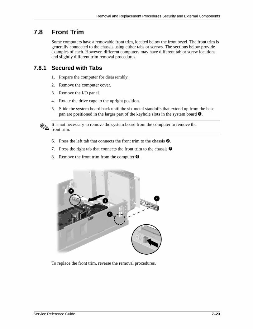
Removal and Replacement Procedures Security and External Components
7.8 Front TrimSome computers have a removable front trim, located below the front bezel. The front trim is generally connected to the chassis using either tabs or screws. The sections below provide examples of each. However, different computers may have different tab or screw locations and slightly different trim removal procedures.
7.8.1 Secured with Tabs
1. Prepare the computer for disassembly.
2. Remove the computer cover.
3. Remove the I/O panel.
4. Rotate the drive cage to the upright position.
5. Slide the system board back until the six metal standoffs that extend up from the base pan are positioned in the larger part of the keyhole slots in the system board 1.
✎ It is not necessary to remove the system board from the computer to remove the front trim.
6. Press the left tab that connects the front trim to the chassis 2.
7. Press the right tab that connects the front trim to the chassis 3.
8. Remove the front trim from the computer 4.
To replace the front trim, reverse the removal procedures.
Service Reference Guide 7–23

Removal and Replacement Procedures Security and External Components
7.8.2 Secured with Screws
1. Prepare the computer for disassembly.
2. Remove the access panel.
3. Remove the front bezel.
4. Remove the two screws connecting the trim to the front of the base pan 1.
5. Remove the trim from the computer 2.
To install the trim, reverse the removal procedure.
✎ When installing the front trim, make sure the three hooks on the bottom of the trim fit into the three associated slots in the base pan.
7–24 Service Reference Guide

8Removal and Replacement Procedures
Expansion Components
ÅWARNING: Power is continuous to the system board and power supply even when the power switch is turned off. To prevent damage to the unit, disconnect the power cord from the power source or the unit before beginning disassembly procedures.
8.1 DrivesWhen installing additional drives, follow these guidelines:
■ For optimal performance, connect hard drives to the primary controller. Connect expansion devices, such as CD-ROM, IDE tape, and diskette drives to the secondary controller.
✎ Refer to chapter 4 for more detailed information on Ultra ATA drives and to chapter 5 for SCSI drives.
■ You must install guide screws to ensure that the drive lines up correctly in the drive cage. Compaq has provided extra guide screws, which are installed in the front of the computer chassis, behind the front bezel. Some options require metric hardware. Compaq-supplied metric screws are black.
■ Drive installation requires no jumper setting changes on the existing or optional drives. All Compaq drives have the jumpers preset for cable-select installation.
■ The system automatically recognizes hard drives sold by Compaq (or any other Plug and Play hard drive) and will automatically reconfigure the computer. If you installed a third-party hard drive, or one that is not a Plug and Play device, you must run Computer Setup to reconfigure the computer.
✎ If installing a second device on the primary controller, you must use an 80-conductor Ultra ATA cable for optimal performance. This cable is available as a Compaq option.
ÄCAUTION: When servicing the computer, ensure that cables are placed in their proper locations during the reassembly process. Improper cable placement can damage the computer.
Service Reference Guide 8–1

Removal and Replacement Procedures Expansion Components
8.1.1 Convertible Minitower
Removing a Drive
1. Prepare the computer for disassembly.
2. Lay the computer down on its large base (side with feet) for greater stability.
3. Remove the access panel.
4. Remove the front bezel.
5. Disconnect the power 1 and data 2 cables from the back of the hard drive.
6. Press the drivelock mechanism to unlock the drives. Drivelock 1 secures the external drives in the desktop configuration; drivelock 2 secures all drives in the minitower configuration and the internal drives in the desktop configuration.
8–2 Service Reference Guide

Removal and Replacement Procedures Expansion Components
7. While holding the drivelock in the unlocked position, remove the drive from the drive bay.
8. Remove the four guide screws from the drive.
9. Install two guide screws on each side of the replacement drive.
✎ Metric screws (M3) have a black finish; U.S. screws have a silver finish.
Replace the drive by reversing the above procedure.
ÄCAUTION: Use only 3/16-inch or 5-mm long screws as guide screws. Longer screws can damage the internal components of the drive.
Installing a New Drive
1. Install two guide screws on each side of the replacement drive 1.
2. Ensure that the guide screws line up with the guide slots 2, then slide the drive into the drive bay until it snaps into place.
3. Connect the power and signal cables to the back of the drive.
4. Remove the bezel blank from the subpanel, if necessary.
5. Reinstall the subpanel and the front bezel.
Service Reference Guide 8–3
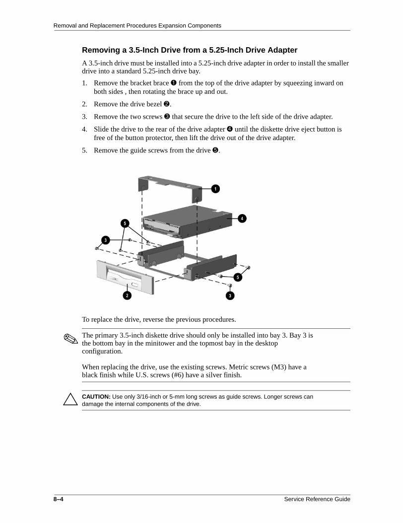
Removal and Replacement Procedures Expansion Components
Removing a 3.5-Inch Drive from a 5.25-Inch Drive Adapter
A 3.5-inch drive must be installed into a 5.25-inch drive adapter in order to install the smaller drive into a standard 5.25-inch drive bay.
1. Remove the bracket brace 1 from the top of the drive adapter by squeezing inward on both sides , then rotating the brace up and out.
2. Remove the drive bezel 2.
3. Remove the two screws 3 that secure the drive to the left side of the drive adapter.
4. Slide the drive to the rear of the drive adapter 4 until the diskette drive eject button is free of the button protector, then lift the drive out of the drive adapter.
5. Remove the guide screws from the drive 5.
To replace the drive, reverse the previous procedures.
✎ The primary 3.5-inch diskette drive should only be installed into bay 3. Bay 3 is the bottom bay in the minitower and the topmost bay in the desktop configuration.
When replacing the drive, use the existing screws. Metric screws (M3) have a black finish while U.S. screws (#6) have a silver finish.
ÄCAUTION: Use only 3/16-inch or 5-mm long screws as guide screws. Longer screws can damage the internal components of the drive.
8–4 Service Reference Guide

Removal and Replacement Procedures Expansion Components
8.1.2 Slim Desktop/Small Form Factor
Drives secured with J-slots have release levers in varying locations near the drive.
Drives Secured with J-slots
1. Prepare the computer for disassembly.
2. Remove the access panel.
3. Disconnect the drive power cable, signal cable, and audio connector from the drive, if applicable.
4. Slide the drive release latch forward 1.
✎ The drive release latch may be in a different location.
5. At the same time, push the drive 2 so the guide screws release from the J-slots, then lift it out of the drive cage 3.
Slim desktop 5.25-inch drive shown
✎ When replacing the drive, transfer the four screws from the old drive to the new one. The screws take the place of drive rails.
To install a drive, reverse the removal procedure.
Service Reference Guide 8–5

Removal and Replacement Procedures Expansion Components
Diskette Drive—Slim Desktop
1. Prepare the computer for disassembly.
2. Remove access panel.
3. Rotate the drive cage to the upright position.
4. Disconnect the drive power cable and signal cable from the drive.
5. Pull the green drive release latch away from the drive 1.
6. Slide the drive out of the drive cage 2.
To install a drive, reverse the removal procedure.
8–6 Service Reference Guide

Removal and Replacement Procedures Expansion Components
Hard Drive—Slim Desktop
1. Prepare the computer for disassembly.
2. Remove the access panel.
3. Rotate the drive cage to the upright position.
4. Lift up to unlock the green drive release latch 1.
5. Slide the hard drive toward the center of the computer, then lift up the back of the hard drive and pull the drive out of the drive cage 2.
6. Disconnect the drive power cable and signal cable from the drive.
To install a drive, reverse the removal procedure.
Service Reference Guide 8–7

Removal and Replacement Procedures Expansion Components
8.1.3 Standard Desktop
Removing the Internal, Side-Mounted, 3.5-Inch Hard Drive
1. Prepare the computer for disassembly.
2. Remove the computer cover.
3. Disconnect the power and data cables from the back of the hard drive.
4. Remove the two screws at the top of the hard drive adapter that connect the adapter to the chassis 1.
5. Slide the adapter to the right until the slots on the bottom of the adapter clear the tabs 2.
6. Tilt and lift the hard drive adapter out of the chassis 3.
✎ The bottom of the adapter must be tilted inward to remove it from the chassis.
7. Remove the drive from the drive adapter by first removing the four screws that connect the drive to the adapter, and then sliding the drive out of the adapter.
To install a side-mounted hard drive, reverse the above procedure.
✎ When installing the drive adapter into the computer, the slots in the bottom of the adapter must be lined up with the tabs in the chassis.
ÄCAUTION: Use only 3/16-inch or 5-mm long screws as guide screws. Longer screws can damage the internal components of the drive.
8–8 Service Reference Guide

Removal and Replacement Procedures Expansion Components
Removing an External 5.25-Inch Drive from the Drive Bay
1. Prepare the computer for disassembly.
2. Remove the computer cover.
3. Disconnect the drive power cable, signal cable, and audio connector, if applicable.
4. Remove the screw from the side of the drive 1.
✎ There may be more than one screw securing the drive in the drive bay.
5. Pull the drive out of the bay 2.
Right drive bay shown
To install a 5.25-inch drive into the drive bay, reverse the above procedure.
✎ It may be necessary to remove a bezel blank.
When replacing the drive, use the existing screws. Metric screws (M3) have a black finish; U.S. screws (#6-32) have a silver finish.
ÄCAUTION: Use only 3/16-inch or 5-mm long screws as guide screws. Longer screws can damage the internal components of the drive.
Service Reference Guide 8–9

Removal and Replacement Procedures Expansion Components
Removing the Diskette Drive
1. Prepare the computer for disassembly.
2. Remove the computer cover.
3. Remove the side-mounted hard drive.
4. Disconnect the data cable and the drive power cable.
5. Facing the drive, remove the retaining screw on the right side of the drive that secures the drive in the bay 1.
6. While pushing down the release latch on the bottom of the bay 2, pull the diskette drive out of the bay 3.
To install a diskette drive, reverse the above procedure.
✎ When installing a new diskette drive, be sure to exchange the guide screws from the old drive.
When replacing the drive, use the existing screws. Metric screws (M3) have a black finish; U.S. screws (#6-32) have a silver finish.
ÄCAUTION: Use only 3/16-inch or 5-mm long screws as guide screws. Longer screws can damage the internal components of the drive.
8–10 Service Reference Guide

Removal and Replacement Procedures Expansion Components
8.1.4 iPAQ Hard Drive
1. Eject the drive from the MultiBay.
2. Prepare the computer for disassembly.
3. Remove the left access panel.
4. Release the green drive latch 1 by pressing the handle and swinging it out from the drive. The drive will swing forward and away 2 from the inner access panel.
5. Disconnect the data 3 and power cables 4 from the back of the hard drive.
6. Lift the drive out of the drive cage.
To install a drive, reverse these procedures.
✎ When installing a drive, always verify that the mounting/guide screws in the new drive are in the same position as in the drive that it is replacing.
When installing the data cable, the colored wire should be closest to the drive’s power cable.
Service Reference Guide 8–11

Removal and Replacement Procedures Expansion Components
8.2 Memory Expansion
8.2.1 440BX
The 440BX comes with at least 16 megabytes of synchronous dynamic random access memory (SDRAM) dual inline memory modules (DIMMs), upgradable to 256 or 384 MB. The memory sockets on the system board can be populated with 16-, 64-, or 128-MB DIMMs. Self-refresh DIMMs are required on models with three DIMM sockets.
For proper system operation, the DIMMs must be industry standard 168-pin, 66-MHz or faster unbuffered SDRAM DIMMs. If your system processor has a bus speed of 66 MHz, Compaq recommends that any additional DIMMs also be 66 MHz. If the system bus speed is 100 MHz, the use of 100-MHz DIMMs is required. (Run Compaq Computer Setup to determine your system bus speed; see the Software Reference Guide for instructions.)
The SDRAM DIMMs must support CAS Latency 2 or 3 (CL = 2 or CL = 3). They must also contain the mandatory Joint Electronic Device Engineering Council (JEDEC) Serial Presence Detect (SPD) information.
DIMMs constructed with x4 SDRAM are not supported; the system will not start using unsupported DIMMs.
8.2.2 Intel 810/810e
✎ The Intel 810 does not support 66-MHz memory.
The Intel 810 comes with at least 32 MB of SDRAM DIMMs, and the Intel 810e comes with at least 64-MB of SDRAM DIMMs, upgradable to 512 MB.
The memory sockets on the system board can be populated with industry-standard DIMMs. These memory module slots are populated by at least one preinstalled memory module. To achieve the maximum memory support, you may be required to replace the preinstalled DIMM with a higher capacity DIMM.
For proper system operation, the DIMMs must be industry standard 168-pin, 100 MHz, unbuffered, PC100-compliant SDRAM DIMMs, depending on the model. The SDRAM DIMMs must support CAS Latency 2 or 3 (CL = 2 or CL = 3). They must also contain the mandatory Joint Electronic Device Engineering Council (JEDEC) Serial Presence Detect (SPD) information. DIMMs constructed with x4 SDRAM are not supported; the system will not start using unsupported DIMMs.
ÄCAUTION: The DIMM sockets have gold metal contacts. When upgrading memory, it Is important to use DIMMs with gold metal contacts (not tin-lead) to prevent corrosion and/or oxidation resulting from having incompatible metals in contact with each other.
8–12 Service Reference Guide

Removal and Replacement Procedures Expansion Components
8.2.3 Intel 815e
The memory sockets on the Intel 815e chipset–based system board can be populated with industry-standard DIMMs. These memory module slots are populated with at least one preinstalled memory module. To achieve the maximum memory support, you may be required to replace the preinstalled DIMM with a higher capacity DIMM.
For proper system operation, the DIMMs must be industry-standard 168-pin, unbuffered PC100- or PC133- compliant SDRAM DIMMs, depending on the model. The SDRAM DIMMs must support CAS Latency 2 or 3 (CL = 2 or CL = 3). They must also contain the mandatory Joint Electronic Device Engineering Council (JEDEC) Serial Presence Detect (SPD) information. DIMMs constructed with x4 SDRAM (16 ICs per side) are not supported; the system will not start using unsupported DIMMs.
The Intel 815e chipset supports both PC100 and PC133 SDRAM DIMMs. PC133 DIMMs should be used for optimal performance. If both PC100 and PC133 SDRAM DIMMs are installed in a computer, the system memory will run at the lower, 100 MHz speed. Some configurations of PC133 SDRAMs may run at 100 MHz instead of 133 MHz.
ÄCAUTION: Your memory module sockets have gold metal contacts. When upgrading your memory, it is important to use memory modules with gold metal contacts to prevent corrosion and/or oxidation resulting from having incompatible metals in contact with each other.
Service Reference Guide 8–13

Removal and Replacement Procedures Expansion Components
8.2.4 Intel 820
The memory sockets on the Intel 820 chipset–based system board can be populated with industry-standard RIMMs. All slots must be occupied by either a memory module or a continuity module (CRIMM). RIMM upgrade kits are available as options from Compaq.
For proper system operation, the RIMMs must be industry-standard 184-pin, PC800–compliant RAMBUS memory modules, depending on the model. They must also contain the mandatory Joint Electronic Device Engineering Council (JEDEC) Serial Presence Detect (SPD) information (1.0 or later)
✎ If you install RIMMs of varying speeds, the system will run at the speed of the slowest installed RIMM.
Follow the guidelines listed below when installing RIMMs:
■ Install RIMMs in pairs across both memory channels. Each RIMM socket populated with a RIMM or CRIMM on Channel A must be populated with an identical RIMM or CRIMM on Channel B. For examples of the correct configuration sequence, refer to the section, “RIMM Installation.”
■ RIMMs must be installed correctly. Be sure to match the two key sockets on the RIMM with the tabs on the RIMM socket. Push the RIMM down into the RIMM socket, ensuring that it is fully inserted and properly seated, and that the retaining arms are locked in place.
■ CRIMMs must be installed in all empty RIMM sockets. The CRIMMs are removed when you populate the sockets with RIMMs. For examples of the correct configuration sequence, refer to the section “RIMM Installation.”
ÄCAUTION: These guidelines must be followed when installing RIMMs or your computer will not function.
ÄCAUTION: Your memory module sockets have gold metal contacts. When upgrading your memory, it is important to use memory modules with gold metal contacts to prevent corrosion and/or oxidation resulting from having incompatible metals in contact with each other.
8–14 Service Reference Guide

Removal and Replacement Procedures Expansion Components
8.2.5 Intel 850
The memory sockets on the Intel 850 chipset–based system board can be populated with pairs of industry-standard RIMMs. All slots must be occupied by either a memory module or a continuity module (CRIMM). RIMM upgrade kits are available as options from Compaq.
For proper system operation, the RIMMs must be industry-standard 184-pin, PC800-compliant RAMBUS memory modules, depending on the model. They must also contain the mandatory Joint Electronic Device Engineering Council (JEDEC) Serial Presence Detect (SPD) information (1.0 or later). Intel 850 chipset–based Deskpro models have two Direct RAMBUS channels.
✎ If you install RIMMs of varying speeds, the system will run at the speed of the slowest installed RIMM.
Follow the guidelines listed below when installing RIMMs:
■ Install RIMMs in pairs across both memory channels. Each RIMM socket populated with a RIMM or CRIMM on Channel A must be populated with an identical RIMM or CRIMM on Channel B. For examples of the correct configuration sequence, refer to the section, “RIMM Installation.”
■ RIMMs must be installed correctly. Be sure to match the two key sockets on the RIMM with the tabs on the RIMM socket. Push the RIMM down into the RIMM socket, ensuring that it is fully inserted and properly seated, and that the retaining arms are locked in place.
■ CRIMMs must be installed in all empty RIMM sockets. The CRIMMs are removed when you populate the sockets with RIMMs. For examples of the correct configuration sequence, refer to Section 8.2.7, “RIMM Installation.”
ÄCAUTION: These guidelines must be followed when installing RIMMs or your computer will not function.
ÄCAUTION: Your memory module sockets have gold metal contacts. When upgrading your memory, it is important to use memory modules with gold metal contacts to prevent corrosion and/or oxidation resulting from having incompatible metals in contact with each other.
Service Reference Guide 8–15

Removal and Replacement Procedures Expansion Components
8.2.6 DIMM Installation
1. If the computer has a locked the Smart Cover Lock, use Computer Setup to unlock the lock and disable the Smart Cover Sensor.
2. Shut down the operating system properly, then turn off the computer and any external devices, then disconnect the power cord from the power outlet.
3. Remove the access panel and locate the memory module sockets.
ÅWARNING: To reduce risk of personal injury from hot surfaces, allow the internal system components to cool before touching.
4. Open both latches of the memory module socket 1, and insert the memory module into the socket 2.
Begin by installing a module into the socket nearest the preinstalled module, and install the modules following the numerical order of the sockets.
A memory module can be installed only one way. Match the notch on the module with the tab on the memory socket. Push the module down into the socket, ensuring that the module is fully inserted and properly seated 3.
✎ When the computer starts up, it will recognize the system memory upgrades and automatically reconfigure the computer.
Do not exceed 1 GB of memory on a system. Exceeding that limit will cause the system to halt.
8–16 Service Reference Guide

Removal and Replacement Procedures Expansion Components
8.2.7 RIMM Installation
Single Memory Channel System
ÅWARNING: To reduce the risk of personal injury when replacing or removing RIMMs, allow the module being removed from the RIMM socket sufficient time to cool. RIMM temperatures can reach 212°F (100°C).
Before installing additional RIMMs, read Sections 8.2.4 and 8.2.5 on the “Intel 820” and “Intel 850” chipsets.
■ CRIMMs or RIMMs must be installed in all unpopulated RIMM sockets.
■ Install RIMMs in pairs across both memory channels. Each RIMM socket populated with a RIMM or CRIMM on Channel A must be populated with an identical device on Channel B.
■ Do not exceed 32 Direct RDRAM devices in each Direct Rambus memory channel. A label on the RIMM will identify the number and speed of Direct RDRAM devices on the RIMM.
■ Do not mix RIMMs with different memory speeds, Performance will always reflect the speed of the slowest component.
■ Use only RIMMs that have been tested and approved by Compaq for quality and reliability.
The four RIMM sockets are numbered XMM1 and XMM2 (Channel A) and XMM3 and XMM4 (Channel B).
When installing RIMMs, you must use the configurations in the following table.
✎ CRIMMs should never be installed in socket XMM1 or XMM3.
RIMM Installation Configurations
Memory Channel A Memory Channel B
Possible Configuration
RIMM Socket XMM1
RIMM Socket XMM2
RIMM Socket XMM3
RIMM Socket XMM4
1 RIMM CRIMM RIMM CRIMM
2 RIMM RIMM RIMM RIMM
Service Reference Guide 8–17

Removal and Replacement Procedures Expansion Components
Dual Memory Channel System
Before installing additional RIMMs, read Sections 8.2.4 and 8.2.5 on the “Intel 820” and “Intel 850” chipsets.
■ CRIMMs or RIMMs must be installed in all unpopulated RIMM sockets.
■ Install RIMMs in pairs across both memory channels. Each RIMM socket populated with a RIMM or CRIMM on Channel A must be populated with an identical device on Channel B.
■ Do not exceed 32 Direct RDRAM devices in each Direct Rambus memory channel. A label on the RIMM will identify the number and speed of Direct RDRAM devices on the RIMM.
■ Do not mix RIMMs with different memory speeds, Performance will always reflect the speed of the slowest component.
■ Use only RIMMs that have been tested and approved by Compaq for quality and reliability.
When installing modules on the eight RIMM socket memory board, you must adhere to one of the following four configurations for best performance .
RIMM Installation Configurations
Memory Channel A Memory Channel B
RIMM Sockets One Pair RIMMs
Two Pair RIMMs
Three Pair RIMMs
Four Pair RIMMs
1 and 2 CRIMM CRIMM RIMM RIMM
3 and 4 RIMM RIMM RIMM RIMM
5 and 6 Empty RIMM RIMM RIMM
7 and 8 Empty CRIMM CRIMM RIMM
8–18 Service Reference Guide

Removal and Replacement Procedures Expansion Components
Installation Procedures
1. Shut down the operating system properly, then turn off the computer and any external devices, then disconnect the power cord from the power outlet.
2. Remove the access panel and locate the memory module sockets.
ÅWARNING: To reduce risk of personal injury from hot surfaces, allow the internal system components to cool before touching.
3. Open both latches of the memory module socket 1, and insert the memory module into the socket 2.
ÄCAUTION: Be sure to follow the correct configuration guidelines respective to your memory board, or your system will not function.
A memory module can be installed only one way. Match the notch on the module with the tab on the memory socket. Push the module down into the socket, ensuring that the module is fully inserted and properly seated 3.
Service Reference Guide 8–19

Removal and Replacement Procedures Expansion Components
8.3 Expansion Card Cage
8.3.1 Removing an Expansion Card Cage
Expansion card cage location and removal procedures may vary.
1. Prepare the computer for disassembly.
2. Remove the computer cover.
3. Pull the expansion card cage straight up to remove it from the chassis.
Small form factor shown
To replace the expansion card cage, reverse the removal procedures.
✎ If the expansion card cage connects to the power supply, when reinstalling the expansion card cage, ensure that the tab on the brace latches into the slot on the side of the power supply.
8–20 Service Reference Guide

Removal and Replacement Procedures Expansion Components
8.3.2 Riser Board
Riser board removal procedures may vary slightly.
1. Prepare the computer for disassembly.
2. Remove the computer cover.
3. Remove the expansion card cage.
4. Remove any expansion cards.
5. Disconnect any cables from the riser board.
6. Remove the screws that secure the riser board to the expansion card cage 1.
7. Slide the board down slightly so it clears the guide slots on the top of the expansion card cage 2.
8. Remove the riser board from the expansion card cage 3.
Small form factor shown
To replace the riser board, reverse the removal procedures.
Service Reference Guide 8–21

Removal and Replacement Procedures Expansion Components
8.4 Expansion Cards—Standard Sockets1. Prepare the computer for disassembly.
2. Remove the access panel.
If installing an expansion card, skip to step 8.
3. To remove an expansion card, disconnect any cables attached to the expansion card.
4. Remove the screw at the top of the expansion slot.
5. Hold the card at each end and carefully rock it back and forth until the connectors pull free from the socket. Be sure not to scrape the card against other components.
6. Store the card in anti-static packaging.
7. Install an expansion slot cover or new expansion card to close the open slot.
If not installing a new expansion card, skip to step 10.
8. Remove the expansion slot cover.
9. Slide the expansion card into the expansion socket and press it firmly into place.
✎ When you install an expansion card, make sure you press firmly on the card so that the entire connector seats properly in the expansion card socket.
10. Replace the screw at the top of the expansion slot.
11. Replace the access panel.
12. Connect external cables to the installed card, if needed.
13. Reconfigure the computer, if necessary.
8–22 Service Reference Guide

Removal and Replacement Procedures Expansion Components
8.5 Graphics Sockets with Retention Mechanisms The AGP expansion socket may come with a retention mechanism installed around it to hold the graphics cards securely in place. There are two different types of retention mechanisms that may be installed around the AGP expansion socket.
8.5.1 Graphics Performance Accelerator (GPA)/AGP Inline Memory Module (AIMM) Card with a Type 1 Retention Mechanism
Removing a GPA/AIMM Card 1. Prepare the computer for disassembly.
2. Remove the access panel.
3. Pull the arm on the right side of the retention mechanism 1.
4. At the same time, rotate the front of the GPA/AIMM card up until it is at a 45 degree angle 2.
5. Remove the card from the expansion socket 3.
Service Reference Guide 8–23

Removal and Replacement Procedures Expansion Components
Installing a GPA/AIMM Card
1. Prepare the computer for disassembly.
2. Remove the access panel.
3. Insert the hook 1 on the left side of the GPA/AIMM card under the loop 2 on the left side of the retention mechanism.
4. Rotate the right side of the card down until it is at a 45 degree angle 3.
5. With the GPA/AIMM card at a 45 degree angle, slide the card back towards the back of the expansion socket 4 until the fingers on the bottom of the card line up properly with the connectors in the expansion socket.
ÄCAUTION: The fingers on the bottom of the GPA/AIMM card must be properly aligned with the expansion slot during installation. Misalignment may result in damage to the card or the AGP connector.
6. While pulling the arm on the right side of the retention mechanism 5, rotate the card down into the expansion socket until seated 6.
8–24 Service Reference Guide

Removal and Replacement Procedures Expansion Components
8.5.2 AGP Card with a Type 1 Retention Mechanism
Removing an AGP Card
1. Prepare the computer for disassembly.
2. Remove the access panel.
3. Remove the screw at the top of the expansion slot.
4. Pull the arm on the right side of the retention mechanism.
5. Pull the card straight up to remove it from the expansion socket.
To install the graphics card, reverse the above procedures.
Service Reference Guide 8–25

Removal and Replacement Procedures Expansion Components
8.5.3 GPA/AIMM Card with a Type 2 Retention Mechanism
Removing a GPA/AIMM Card
1. Prepare the computer for disassembly.
2. Remove the access panel.
3. Pull the arm on the right side of the retention mechanism.
4. Pull the card straight up to remove it from the expansion socket.
To install the graphics card, reverse the above procedures.
8–26 Service Reference Guide

Removal and Replacement Procedures Expansion Components
8.5.4 AGP Card with a Type 2 Retention Mechanism
Removing an AGP Card
1. Prepare the computer for disassembly.
2. Remove the access panel.
3. Remove the screw at the top of the expansion slot.
4. Pull the arm on the right side of the retention mechanism.
5. Pull the card straight up to remove it from the expansion socket.
To install the graphics card, reverse the above procedures.
Service Reference Guide 8–27

Removal and Replacement Procedures Expansion Components
8.5.5 AGP with Type 1 or Type 2 Retention Mechanism
1. Prepare the computer for disassembly.
2. Remove the access panel.
3. Remove the screw at the top of the expansion slot.
4. Remove the AGP graphics card as you would any PCI expansion card.
To install the graphics card, reverse the above procedures.
8–28 Service Reference Guide

Removal and Replacement Procedures Expansion Components
8.6 iPAQ Graphics Memory Cache1. Prepare the computer for disassembly.
2. Remove the right access panel.
3. Remove the inner access panel.
4. Pull straight up on the cache module to disengage it from the socket on the system board.
To install the cache module, reverse the above procedures. The cache module has a large pin on one corner that ensures proper orientation.
Service Reference Guide 8–29

Removal and Replacement Procedures Expansion Components
8.7 iPAQ Legacy Module1. Prepare the computer for disassembly.
2. Pull the Legacy Module from the connector on the I/O panel.
To install the Legacy Module, align the Legacy Module over the connector on the I/O panel and snap into place.
8–30 Service Reference Guide

Removal and Replacement Procedures Expansion Components
8.8 iPAQ MultiBay Board1. Prepare the computer for disassembly.
2. Eject the drive from the MultiBay if necessary.
3. Remove the left access panel.
4. Remove the two screws securing the MultiBay board to the housing.
5. Remove the board by pulling it straight out of the system board.
✎ The MultiBay board is keyed for proper orientation.
To install the MultiBay board, reverse the above procedure.
Service Reference Guide 8–31

Removal and Replacement Procedures Expansion Components
8–32 Service Reference Guide

9Removal and Replacement Procedures
Small Components
ÄCAUTION: When the computer is plugged into an AC power source, voltage is always applied to the system board. You must disconnect the power cord from the power source before opening the computer to prevent system board or component damage.
9.1 BatteryThe battery that comes with the computer provides power to the real-time clock and has a lifetime of about three years. When replacing the battery, use the appropriate 3-volt lithium coin cell battery. To replace the battery:
1. Prepare the computer for disassembly.
2. Remove the access panel.
3. Move/remove any components necessary to gain access to the battery.
4. Lift the battery out of its holder.
5. Slide the replacement battery into position with the “plus” side up.The battery holder automatically secures the battery in the proper position.
Service Reference Guide 9–1

Removal and Replacement Procedures Small Components
6. Replace the access panel.
7. Plug in the computer and turn on power.
8. Reset the date, time, passwords, and any special system settings, using Compaq Computer Setup.
✎ If you previously saved your CMOS settings to a diskette with F10 setup, you can restore these CMOS settings using F10 setup and the diskette with the saved CMOS configuration.
ÅWARNING: This computer contains a lithium-ion battery pack. There is a risk of fire and chemical burn if the battery pack is handled improperly. Do not disassemble, crush, puncture, short external contacts, dispose in water or fire, or expose it to temperatures higher than 140ºF (60ºC).
NIn North America, dispose of nickel metal hydride or lithium-ion batteries by taking advantage of the Compaq battery recycling program. You will be provided with a postage-paid battery pack mailer preaddressed to a reclamation facility where the metals are recycled. Call the telephone number listed for your location in the Contacting Customer Support guide for more information. In Europe, do not dispose of batteries with general household waste. Dispose of or recycle them by using the public collection system or returning them to Compaq, your authorized Compaq partners, or their agents.
9–2 Service Reference Guide

Removal and Replacement Procedures Small Components
9.2 Speaker
9.2.1 Standard Speaker
1. Prepare the computer for disassembly.
2. Remove the access panel.
3. Move/remove any components necessary to gain access to the speaker.
4. Disconnect the speaker wire from the P6 connector 1.
5. Remove the four screws that connect the speaker to the chassis.
6. Remove the speaker.
To install the speaker, reverse the removal procedure.
Service Reference Guide 9–3

Removal and Replacement Procedures Small Components
9.2.2 iPAQ Speaker
1. Prepare the computer for disassembly.
2. Remove both the left and right outer access panels.
3. Remove the inner access panel.
4. Remove the speaker grill.
5. Disconnect the audio cable from the system board 1.
6. Remove the four screws from the front of the chassis that secure the speaker to the chassis.
7. Remove the speaker from the chassis.
To replace the speaker, reverse the previous steps making sure that the wire leads on the speaker are pointing down towards the bottom of the chassis.
9–4 Service Reference Guide
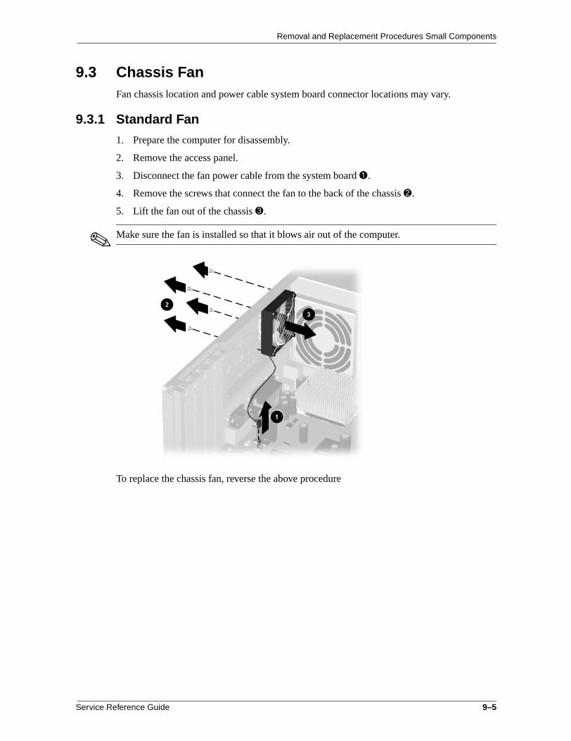
Removal and Replacement Procedures Small Components
9.3 Chassis FanFan chassis location and power cable system board connector locations may vary.
9.3.1 Standard Fan
1. Prepare the computer for disassembly.
2. Remove the access panel.
3. Disconnect the fan power cable from the system board 1.
4. Remove the screws that connect the fan to the back of the chassis 2.
5. Lift the fan out of the chassis 3.
✎ Make sure the fan is installed so that it blows air out of the computer.
To replace the chassis fan, reverse the above procedure
Service Reference Guide 9–5

Removal and Replacement Procedures Small Components
9.3.2 Chassis Fan with Cover
1. Prepare the computer for disassembly.
2. Remove the access panel.
3. Disconnect the fan power cable from the system board 1.
4. Press down on both tabs on the back of the fan 2.
5. From the front of the computer, slide the fan to the left until the hooks clear the notches in the chassis 3.
6. Pull the fan assembly toward the front and then lift it out of the computer.
To install the fan, reverse the removal procedure.
9–6 Service Reference Guide

Removal and Replacement Procedures Small Components
9.4 Air BafflesComputers are sometimes equipped with internal air baffles that redirect air flow in order to help regulate internal temperature. This section contains examples of the types of baffles currently being used. The baffle in your computer may vary.
ÄCAUTION: Always reinstall an air baffle after it has been removed. Failure to do so may cause the computer to overheat and could result in loss of data or damage to the computer.
9.4.1 Type 1 Baffle
Component Access Without Removal
To gain access to the heatsink, the air baffle can be disassembled and lifted out of the way while still attached to the computer. The chassis fan does NOT have to be removed to disassemble the air baffle while it is in the computer.
1. Prepare the computer for disassembly.
2. Remove the access panel.
3. Remove the three tabs from the slots on both sides of the air baffle 1.
4. Lift up the main flap of the air baffle. The baffle is perforated to make it easy to maneuver without completely removing it from the chassis.
ÄCAUTION: Do not force the baffle or it could tear.
✎ The air baffle remains connected to the chassis fan. The remove the air baffle from the computer, the chassis fan must be removed from the unit.
To reassemble the air baffle, reverse the above procedure.
Service Reference Guide 9–7

Removal and Replacement Procedures Small Components
Baffle Removal
The example in this section has the air baffle connected to the chassis fan. When removing the fan, you also have to remove the air baffle from the chassis. Air baffles may vary based on model.
1. Prepare the computer for disassembly.
2. Remove the access panel.
3. Disassemble the air baffle.
4. Disconnect the fan power cable from the system board.
5. Remove the four screws that secure the fan to the chassis 1.
6. Remove the fan from the chassis 2.
7. Remove the three tabs from the associated slots in the air baffle that are located on the top and on the bottom of the chassis fan.
8. Remove the air baffle from the fan 3.
To install the fan/air baffle assembly, reverse the above procedure.
✎ When installing the fan/air baffle assembly, be sure to place the chassis fan power cable through the opening in the air baffle.
9–8 Service Reference Guide

Removal and Replacement Procedures Small Components
9.4.2 Type 2 Baffle
Baffle Removal
The example in this section has the air baffle connected to the chassis fan. When removing the fan, you also have to remove the air baffle from the chassis. Air baffles may vary based on model.
1. Prepare the computer for disassembly.
2. Place the computer in the desktop position.
3. Remove the access panel.
4. Gently pull on the air baffle 1 until it comes loose from the fan assembly 2.
5. Slide the air baffle under the cables 2 for bays 1, 2, and 3.
6. Lift the air baffle from the chassis.
Service Reference Guide 9–9

Removal and Replacement Procedures Small Components
9.5 Power Switches and Switch Cables
9.5.1 Switch Secured with Screws
1. Prepare the computer for disassembly.
2. Remove the access panel.
3. Move/remove any components necessary to gain access to the power switch.
4. Disconnect the power cable from the system board 1.
5. Remove the two screws connecting the board to the chassis.
6. Remove the board from computer 2.
To install the power button/LED board, reverse the above procedure.
9–10 Service Reference Guide

Removal and Replacement Procedures Small Components
9.5.2 Switch Secured with Tabs—Type 1
1. Prepare the computer for disassembly.
2. Remove the access panel.
3. Remove the front bezel, if necessary.
4. Move/remove any components necessary to gain access to the power switch.
5. Disconnect the power/LED cable from the system board 1.
6. Push the release tab 2 toward the drive bays, then remove the power switch assembly from the chassis.
To install the new power switch, reverse the above procedure, pushing the switch assembly until it snaps into place. The power/LED connector is keyed to ensure proper installation.
Service Reference Guide 9–11

Removal and Replacement Procedures Small Components
9.5.3 Switch Secured with Tabs—Type 2
1. Prepare the computer for disassembly.
2. Remove the computer cover.
3. Disconnect the flat ribbon cable and the CD audio cable from the CD-ROM drive.
4. Disconnect the power/LED cable from the system board 1.
5. Pinch the two tabs of the power switch assembly together 2 and pull the assembly 3 from the chassis.
6. Pinch the two tabs of the Drive Activity Light assembly together 2 and pull the assembly 4 from the chassis.
7. Pinch the two tabs of the Power-on Light assembly together 2 and pull the assembly 5 from the chassis.
To install a power switch/LED cable, reverse the above procedure.
9–12 Service Reference Guide

Removal and Replacement Procedures Small Components
9.6 Board Guide1. Prepare the computer for disassembly.
2. Remove the access panel.
3. Move/remove any components necessary to gain access to the board guide.
4. Remove any full-length expansion boards.
5. Push down on the two tabs on the side of the board guide.
6. While holding the tabs down, remove the guide from the chassis.
Convertible minitower shown
To replace the board guide, reverse the above procedure.
Service Reference Guide 9–13

Removal and Replacement Procedures Small Components
9–14 Service Reference Guide

10Removal and Replacement Procedures
Base Components
ÄCAUTION: When the computer is plugged into an AC power source, voltage is always applied to the system board. You must disconnect the power cord from the power source before opening the computer to prevent system board or component damage.
10.1 System Board The illustrations below provide examples of typical system board screw locations. Screw locations vary based on computer.
✎ If the processor must be removed from the system board, the heatsink must be replaced with a new one and the top of the processor must be cleaned of all thermal pad residue before reinstallation.
Use an alcohol wipe to remove all thermal pad residue from the top of the processor. These wipes are available at most drug stores and electronic supply stores.
If the heatsink has a thermal interface attached to its bottom, peel off the protective paper (if present) before installing the heatsink. A thermal interface pad must be used between the heatsink and the processor for proper cooling.
ÄCAUTION: The top of the processor must be free of all thermal pad residue and the replacement heatsink must have a new thermal pad installed to prevent the processor from overheating. Thermal interface heat transmission is reduced if residue remains on the processor. This could lead to the processor running at a higher than normal temperature and could cause premature processor failure.
ÄCAUTION: Check the position of all cables and wires before raising or lowering the drive cage to prevent cable damage.
10.1.1 System Board Secured with Screws
1. Prepare the computer for disassembly.
2. Remove the access panel.
3. Remove all expansion boards.
4. Remove all graphics cards.
5. Disconnect all cables connected to the system board, noting their location for reinstallation.
Service Reference Guide 10–1

Removal and Replacement Procedures Base Components
6. Remove/move the baffle, as necessary.
7. Remove the screws connecting the system board to the chassis.
✎ Some system boards may be secured with screws located in the heatsink mounting brackets. In this case, the heatsink must be removed to access the screws. These screws will be longer than others used to secure the system board.
8. Slide the system board toward the front of the chassis until the external connectors are clear of the I/O panel.
9. Lift the system board out of the computer.
Standard screw locations
System board with screws in heatsink brackets
To install a system board, reverse the removal procedure.
10–2 Service Reference Guide

Removal and Replacement Procedures Base Components
10.1.2 System Board Removal—Small Form Factor
1. Prepare the computer for disassembly.
2. Remove the computer cover.
3. Remove the expansion card cage.
4. Rotate the power supply to the upright position.
5. Disconnect all cables from the system board 1.
6. Press the green release tab on the end of the I/O panel 2.
7. Swing the I/O panel away from the computer 3 until it is at a 90 degree angle.
8. Remove the panel from the chassis 4.
Service Reference Guide 10–3

Removal and Replacement Procedures Base Components
9. Slide the system board toward the rear of computer until the metal standoffs that extend up from the base pan are positioned in the larger part of the keyhole slots in the system board 1.
10. Raise the rear of the system board until it is at a 30 degree angle 2; then remove the system board by pulling it toward the rear of the computer, then lifting it up and out of the chassis 3.
To replace the system board, reverse the removal procedures.
10–4 Service Reference Guide

Removal and Replacement Procedures Base Components
10.1.3 iPAQ System Board Removal
1. Eject the drive from the MultiBay if necessary.
2. Prepare the computer for disassembly.
3. Remove both outer access panels.
4. Remove the MultiBay board.
5. Remove the hard drive.
6. Remove the right inner access panel.
7. Remove the I/O panel by pushing it out of the chassis from the inside.
8. Lay the computer down on its side for greater stability.
✎ Place a protective pad beneath the computer to protect it.
9. Disconnect any cables that are attached to the system board, noting their location for reinstallation.
Service Reference Guide 10–5

Removal and Replacement Procedures Base Components
10. Remove the four retaining screws that secure the system board to the chassis.
11. Slide the board about 0.5 inches toward the rear of the chassis, then lift it up and out of the chassis.
12. To install a system board, angle the system board toward the I/O panel opening, then set the board on the chassis.
13. Install the retaining screws to secure the system board to the chassis.
14. Install the I/O panel. The panel is set correctly when you hear it click into place.
15. Complete the installation process by reversing steps 3 through 6 above.
10–6 Service Reference Guide

Removal and Replacement Procedures Base Components
10.2 Power Supply1. Prepare the computer for disassembly.
2. Remove the access panel.
3. Disconnect all power cables from the mass storage devices and the system board 1.
4. Remove the screws that connect the power supply to the chassis 2.
✎ There may be a screw connecting the power supply to the bottom of the chassis.
5. Slide the power supply toward the front of the computer until it clears the notches in the base pan, then lift it out of the computer 3.
Slim desktop shown
To install the power supply, reverse the removal procedure.
Service Reference Guide 10–7

Removal and Replacement Procedures Base Components
10.3 Processor and Heatsink
10.3.1 Guidelines for Separating the Heatsink/Processor Assembly
The following sequential events must take place in order to remove the existing heatsink and processor assembly:
1. The heatsink and processor assembly is to be heated to an optimum temperature to break the compound bonding them together. See the following sections:
❏ “Heatsink Cool-Down Time”
❏ “Heatsink Warm-Up Time”
2. The heatsink is to be separated from the processor.
3. The processor is to be released from the processor socket.
Heatsink Cool-Down Time
The heat generated from the processor core transfers to the heatsink making the assembly too hot to handle. Once the system has been turned off, it takes approximately 13 minutes before the heatsink has cooled down enough to be safe to touch, and the compound holding it to the processor remains pliable.
Heatsink Warm-Up Time
Minimal warm-up time is required to generate enough heat to soften the compound holding the heatsink to the cold processor.
ÄCAUTION: Lifting the heatsink straight up while it is in a cold state can result in damage to the processor, because it may prematurely pull the heatsink and processor assembly out of the processor socket. If this should occur, you will need to open the processor socket, by lifting up on the processor retention lever, before attempting to install the new processor.
When turning the computer on, see the following steps to warm (but not overheat) the heatsink so it can be handled comfortably, and the compound holding it to the processor will be pliable.
1. Turn on the workstation and allow the operating system to boot.
2. Shut down the operating system properly, then turn off the workstation and any external devices.
3. Disconnect the power cord from the grounded AC outlet.
10–8 Service Reference Guide

Removal and Replacement Procedures Base Components
10.3.2 Processor Installation 1. Place the processor into the ZIF socket by orienting the pins on the processor assembly
with the socket. The processor fits only one way into the socket. Do not force the processor into the socket.
✎ The processor should be installed on the system board prior to cleaning to prevent damaging its pins.
2. Clean the top of the processor using an alcohol wipe that is available at most drug stores and electronic supply stores. If you are reusing an existing processor, be sure that all of the residue from the original thermal pad has been removed.
ÄCAUTION: Residue on top of the processor could result in the system overheating and could cause a computer failure.
3. After the alcohol used to clean the processor has evaporated, install the new heatsink with its new thermal pad on top of the processor and latch it securely in place.
CAUTION: If only one processor is installed, and you are replacing that processor, be sure to install the processor in the primary processor socket or your workstation will not function.
10.3.3 Multiprocessor Information
Some workstations have multiprocessor capability. When you install a second processor, it must be the same speed, cache size, and type as the existing processor.
ÄCAUTION: A primary processor must be installed in the primary processor slot when installing a second processor or the workstation will not function.
Multiprocessor systems require the installation of a Voltage Regulator Module (VRM) for each processor installed.
ÄCAUTION: You must install a Compaq approved VRM board when installing a second processor. Using a VRM board that is incompatible with the primary VRM b oard may severly or permanently damage the system board.
Service Reference Guide 10–9

Removal and Replacement Procedures Base Components
Hardware Abstraction Layer
To update Windows NT 4.0 or Windows 2000 to recognize a second processor using the Hardware Abstraction Layer (HAL), complete the following steps:
1. Start Windows.
2. Insert the upgrade diskette. Then select Start > Run.
3. Type
A:\setup.exe
and select OK.
4. Select Uniprocessor HAL and Kernel.
5. Select Upgrade and insert the media used to upgrade the operating system to a new Service Pack if requested; then click Retry.
6. If prompted, insert the operating system CD and click OK.
7. After the installation is complete, close the setup program and restart the computer.
✎ A manual Hardware Abstraction Layer (HAL) upgrade is necessary when installing a second processor after the system has gone through the software bundling process. If a second processor is installed prior to unbundling, a manual upgrade is not necessary.
10.3.4 Heatsink Installation
1. Install the new heatsink and secure it in place making sure the heatsink clips are properly installed and securely latched.
✎ If the heatsink has a thermal interface attached to its bottom, peel off the protective paper (if present) before installing the heatsink.
2. If an active heatsink, connect the power lead from the heatsink to the system board.
✎ After installing a new processor onto a system board, always update the system ROM to ensure that the latest version is being used on the computer. The latest System ROMPaq may be found on the Compaq Web site at www.compaq.com/support/files.
ÅWARNING: To reduce the risk of personal injury from hot surfaces, allow the internal system components to cool befire touching.
10–10 Service Reference Guide

Removal and Replacement Procedures Base Components
10.3.5 Heatsink Removal Methods
Single Clip Heatsink
1. Prepare the computer for disassembly.
2. Remove the access panel.
3. Unplug the fansink wire from the system board, and remove the fansink from the top of the heatsink 1, if necessary.
4. Remove the heatsink retaining clip 2 by pressing down on the clip’s extended tab until it releases from the safety catch.
5. Twist the heatsink 2 slightly to break its adhesion to the processor and remove the heatsink from the processor.
6. Release the processor by pulling the handle on the ZIF socket 3 out and upward.
7. Lift the processor out of the socket 4.
To install a processor, reverse the removal procedures.
Service Reference Guide 10–11

Removal and Replacement Procedures Base Components
Dual Clip Heatsink
1. Prepare the computer for disassembly.
2. Remove the access panel.
3. Remove the tabs from the slots in the air baffle and lift it away from the processor.
4. Remove the heatsink retaining clips 1 by pressing down on the clip’s extended tabs until they release from the safety catch, then lifting the clips off of the heatsink.
5. Twist the heatsink 2 clockwise to break the thermal pad seal, then lift the heatsink off the processor.
6. Pull the processor retention lever on the ZIF socket out and upward 3 to release the processor 4 from the socket.
7. Lift the processor 4 out of the socket.
To install a new processor, reverse this procedure.
10–12 Service Reference Guide

Removal and Replacement Procedures Base Components
Round Heatsink
1. Prepare the computer for disassembly.
2. Remove the computer cover.
3. Remove the expansion card cage, if necessary.
4. Unplug the fansink wire from the system board, if necessary 1.
5. Press the tab down and inward toward the heatsink to release the metal clip on the bottom of the tab from the plastic retainer on the processor socket 2.
6. Release the processor from the socket by pulling the handle on the ZIF socket out and upward 3.
7. Lift the processor out of the socket 4.
To install a new processor, reverse this procedure.
Service Reference Guide 10–13

Removal and Replacement Procedures Base Components
10.4 Removing Drivelocks—Convertible Minitower The computer chassis contains two drivelock mechanisms. Drivelock 1 secures the external drives in the desktop configuration, drivelock 2 secures all drives in the minitower and the internal drives in the desktop configuration.
1. Prepare the computer for disassembly.
2. Lay the computer down on its large base (side with feet) for greater stability.
3. Remove the access panel.
4. Remove the front bezel.
5. Remove all of the drives from the computer.
6. While standing at the rear of the unit, push the top drivelock assembly toward the front of the drive cage.
7. Lift up on the side of the drivelock mechanism nearest you, snapping the tabs out of the holes in the drive cage.
ÄCAUTION: The spring contained under the drivelock mechanism may pop out unexpectedly.
8. Remove the drivelock from the drive cage.
10–14 Service Reference Guide

Removal and Replacement Procedures Base Components
9. Remove the spring from the drivelock (see inset).
10. Press in on the tabs to release the vertical drivelock from the chassis, then lift it up and out of the system while at the same time rotating the drivelock slightly to clear the travel slots at the bottom of the drivelock.
11. Remove the spring from the post (see inset).
To reinstall the vertical drivelock, reverse the previous procedure.
Service Reference Guide 10–15

Removal and Replacement Procedures Base Components
To reinstall the horizontal drivelock:
1. Insert the left side of the drivelock (with the rounded tabs) into the slots on the drive cage.
2. Place the washer on the middle tab on the underside of the drivelock.
3. Compress the spring, then lower the drivelock onto the drive cage until it snaps into place.
10–16 Service Reference Guide

Removal and Replacement Procedures Base Components
10.5 Converting a Desktop to a Minitower1. Prepare the computer for disassembly.
2. Lay the computer down on its large base for greater stability.
3. Remove the access panel.
4. Remove the front bezel.
5. Remove the drives from the 5.25-inch drive bays by pressing drivelock 1 for desktop configuration, drivelock 2 for minitower configuration.
6. Rotate the drives 90 degrees, then reinstall them into the drive bays.
✎ The diskette drive should always be placed in bay number 3, the bay nearest the internal 3.5-inch drives, for proper placement within the chassis.
ÄCAUTION: The use of unnecessary force may result in damage to the drives.
7. Reconnect the power, signal, and audio cables to the drives.
Minitower configuration Desktop configuration
Service Reference Guide 10–17

Removal and Replacement Procedures Base Components
8. Remove the subpanel and rotate the bezel blanks 90 degrees.
ÄCAUTION: Hold the subpanel straight when you pull it away from the front bezel. Pulling the subpanel away at an angle could damage the pins that align it within the front bezel.
1 = Desktop configuration; 2 = Minitower configuration
9. Replace the subpanel, front bezel, and the computer access panel.
10. Reassemble the computer.
10–18 Service Reference Guide

Removal and Replacement Procedures Base Components
10.6 Removing the Slim Desktop Hard Drive Latch1. Prepare the computer for disassembly.
2. Remove the access panel.
3. Remove the hard drive(s).
4. Flex the latch by pressing it on its side to disengage the retaining pin from the chassis 1.
5. Lift the latch out of the chassis 2.
To install a new latch, reverse this procedure.
Service Reference Guide 10–19

Removal and Replacement Procedures Base Components
10–20 Service Reference Guide

AConnector Pin Assignments
This appendix contains the pin assignments for many computer and workstation connectors. Some of these connectors may not be used on the product being serviced.
Enhanced Keyboard
Connector and Icon Pin Signal
123
DataUnusedGround
456
+5 VDCClockUnused
Mouse
Connector and Icon Pin Signal
123
DataUnusedGround
456
+5 VDCClockUnused
Ethernet BNC
Connector and Icon Pin Signal
1 (Inside) Data
2 (Outside) Ground
Service Reference Guide A–1

Connector Pin Assignments
Ethernet RJ-45
Connector and Icon Pin Signal
1234
(+) Transmit Data(-) Transmit Data(+) Receive DataUnused
5678
Unused(-) Receive DataUnusedUnused
Ethernet AUI
Connector and Icon
Pin Signal Pin Signal
1234
GroundNegative AUI Differential CollisionPositive AUI Differential CollisionNegative AUI DifferentialTransmit
9101112
Positive AUI Differential Receive+12VGroundGround
5678
Positive AUI DifferentialTransmitGroundGroundNegative AUI Differential Receive
13141516
UnusedUnusedUnusedUnused
A–2 Service Reference Guide

Connector Pin Assignments
Parallel Interface
Connector and Icon
Pin Signal Pin Signal Pin Signal
123
StrobeData Bit 0Data Bit 1
789
Data Bit 5Data Bit 6Data Bit 7
131415
SelectAuto LinefeedError
456
Data Bit 2Data Bit 3Data Bit 4
101112
AcknowledgeBusyPaper End
161718-25
Initialize PrinterSelect INSignal Ground
Serial Interface
Connector and Icon Pin Signal
123
Carrier DetectReceive DataTransmit Data
456
Data Terminal ReadySignal GroundData Set Ready
789
Request to SendClear to SendRing Indicator
USB
Connector and Icon Pin Signal
1234
VCC- Data+ DataGround
Service Reference Guide A–3

Connector Pin Assignments
Microphone
Connector and Icon (1/8” miniphone) Pin Signal
1 (Tip) Audio
2 (Ring) Power
3 (Shield) Ground
Headphone
Connector and Icon (1/8” miniphone) Pin Signal
1 (Tip) Audio_Left
2 (Ring) Audio_Right
3 (Shield) Ground
Line-In Audio
Connector and Icon (1/8” miniphone) Pin Signal
1 (Tip) Audio_In_Left
2 (Ring) Audio_In_Right
3 (Shield) Ground
Line-Out Audio
Connector and Icon (1/8” miniphone) Pin Signal
1 (Tip) Audio_Out_Left
2 (Ring) Audio_Out_Right
3 (Shield) Ground
1 2 31 2 3
1 2 3
1 2 3
1 2 3
A–4 Service Reference Guide

Connector Pin Assignments
SCSI Low Voltage Differential/Single Ended (LVD/SE)
Connector and Icon
Pin Signal Pin Signal Pin Signal Pin Signal
1-1617-1819
GroundTERMPWRReserved
404142
-D0-D1-D1
49-5051-5253
GroundTERMPWReserved
606162
-MSG-SEL-C/D
20-343536
Ground-D12-D13
434445
-D3-D4-D5
545556
Ground-ATNGround
636465
-REQ-I/O-D
373839
-D14-D15-DP1
464748
-D6-D7-DP0
575859
-BSY-ACK-RST
666768
-D-D-D
Ultra SCSI
Connector and Icon
Pin Signal Pin Signal Pin Signal Pin Signal
1-11121314
GroundReservedOpenReserved
29303132
DB3DB4DB5DB6
37383940
ReservedTERMPWRReservedGround
45464748
RST #MSG #SEL #C/D
15-25262728
GroundDB0DB1DB2
33343536
DB7DBPGroundGround
41424344
ATN #GroundBSY #ACK #
4950
REQ #Input/Output
Service Reference Guide A–5
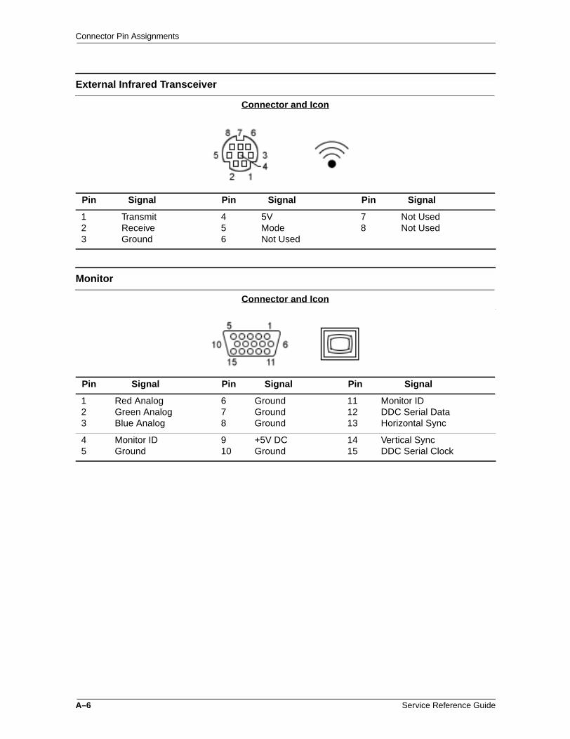
Connector Pin Assignments
External Infrared Transceiver
Connector and Icon
Pin Signal Pin Signal Pin Signal
123
TransmitReceiveGround
456
5VModeNot Used
78
Not UsedNot Used
Monitor
Connector and Icon
Pin Signal Pin Signal Pin Signal
123
Red AnalogGreen AnalogBlue Analog
678
GroundGroundGround
111213
Monitor IDDDC Serial DataHorizontal Sync
45
Monitor IDGround
910
+5V DCGround
1415
Vertical SyncDDC Serial Clock
A–6 Service Reference Guide

Connector Pin Assignments
IDE/EIDE Drive Cable
Connector
Pin Signal Pin Signal Pin Signal
12345
ResetGroundDD7DD8DD6
1516171819
DD1DD14DD0DD15Ground
2930313233
DMAKGroundINTRQIOCS16DA1
678910
DD9DD5DD10DD4DD11
2021222324
(Key)DMARQGroundDIOWGround
3435363738
PDIAG (cable detect)DA0DA2CS1FXCS3FX
11121314
DD3DD12DD2DD13
25262728
DIORGroundIORDYCSEL
3940
DASPGround
Service Reference Guide A–7

Connector Pin Assignments
Slimline CD-ROM Adapter
Connector
Pin Signal Pin Signal Pin Signal Pin Signal
12345
RESDRV_GROUNDD07D08D06
1819202122
D15GROUND(key)DRQGROUND
3536373839
A0A2CS1FXCS3FXDASP
5253545556
FP05FP06FP07FP08FP09
678910
D09D05D10D04D11
2324252627
IOWGROUNDIORGROUNDIOCHDRY
4041424344
GROUND+5VMLOG-5VMOTGROUNDAUDIO_L
5758596061
FP10FP11FP12FP13FP14
1112131415
D03D12D02D13D01
2829303132
CABLE SELECTDAKGROUNDIRQIO16
4546474849
A_GROUND_RA_GROUND_Iaudio_rFP01FP02
6263646566
FP15FP16FP17FP18FP19
1617
D14D00
3334
A1PDIAG
5051
FP03FP04
6768
FP20FP21
A–8 Service Reference Guide

Connector Pin Assignments
Accelerated Graphics Port (AGP)
Connector
Pin Signal A Signal B Pin Signal A Signal B
12345
+12 VTYPEDET#ReservedUSB-Ground
OVRCNT#+ 5V + 5V USB+Ground
3435363738
Vddq AD22AD20GroundAD18
Vddq AD21AD19GroundAD17
678910
INTA#RST#GNT#VCC3.3ST1
INTB#CLKREQ#VCC3.3ST0
3940414243
AD16VddqFRAME#ReservedGround
C/BE2#VddqIRDY#3.3VAuxGround
1112131415
ReservedPIPE#GroundWBF#SBA1
ST2RBF#GroundReservedSBA0
4445464748
ReservedVCC 3.3TRDY#STOP#PME#
ReservedVCC 3.3DEVSEL#Vddq PERR#
1617181920
VCC 3.3SBA3SB_STB#GroundSBA5
VCC 3.3SBA2SB_STBGroundSBA4
4950515253
GroundPARAD15VddqAD13
GroundSERR#C/BE1#VddqAD14
2122232425
SBA7ReservedGroundReservedVCC 3.3
SBA6ReservedGround3.3 VauxVCC 3.3
5455565758
AD11GroundAD9C/BE0#Vddq
AD12GroundAD10AD8Vddq
2627282930
AD30AD28VCC 3.3AD26AD24
AD31AD29
VCC 3.3AD27AD25
5960616263
AD_STB0#AD6GroundAD4AD2
AD_STB0AD7GroundAD5
AD3
313233
GroundAD_STB1#C/BE3#
GroundAD_STB1AD23
646566
Vddq AD0VREFGC
VddqAD1VREFCG
Service Reference Guide A–9

Connector Pin Assignments
IDE CD-ROM
Connector
Pin Signal Pin Signal Pin Signal Pin Signal
12345
RESDRV_ D06D04D02D00
1415161718
GROUNDD09D11D13D15
2728293031
D07D05D03D01Ground
40 41424344
D08D10D12D14(KEY)
678910
DREQIORDAKA1CS1FX
1920212223
GroundGroundGroundPDIAGCS3FX
3233343536
IOWOCHRDYIRQA0DASP
4546474849
GroundCABLE SELECTIO16A2Ground
111213
AUDIO_R+5VMOT1+5VMLOG1
242526
AUDIO_L+5VMOT2+5VMLOG2
373839
A_GND_R+5VMOT3DASP
4950
A_GND_L+5VMOT4
14-Pin Power
Connector for BX Chipset
Pin Signal Pin Signal Pin Signal Pin Signal
1234
+3.3 V+3.3 V SenseRTN+5 V
5678
RTN+5 VRTN+3.3 V
9101112
-12 vFan OFFON/STBY+5 V Aux
1314
+3.3 V Sense return+12 V
1
2
13
14
A–10 Service Reference Guide

Connector Pin Assignments
14-Pin Power
Connector for 810, 810e, and 820 Chipsets
Pin Signal Pin Signal Pin Signal Pin Signal
1234
+3.3 V+3.3 V AuxRTN+5 V
5678
RTN+5 VRTN+3.3 V
9101112
-12 vFan OFFON/STBY+5 V Aux
1314
Fan speed+12 V
20-Pin Power - Deskpro EP
Connector
Pin Signal Pin Signal Pin Signal Pin Signal
12345
+3.3 V+3.3 VRTN+5 VRTN
678910
+5 VRTNFan OFF+5 V Aux+12 V
1112131415
+3.3 V-12 VRTNON/STBYRTN
1617181920
RTNRTN-5 V+5 V+5 V
1
2
13
14
1
2
19
20
Service Reference Guide A–11

Connector Pin Assignments
20-Pin Power - Deskpro EN
Connector
Pin Signal Pin Signal Pin Signal Pin Signal
12345
3 V3 V/RSRTN+5 VRTN
678910
+5 VAux RTNFan OFF+5 V Aux+12 V
1112131415
+3 V-12 VRTNON/STBYRTN
1617181920
RTN/RSRTN-5 V+5 V+5 V
24-Pin Power - Power
Connector
Pin Signal Pin Signal Pin Signal Pin Signal
123456
+3.3 V+3.3 VRTN+5 VRTN+5 V
789101112
Aux RTNFan OFF+5 V Aux+12 V3.3 V AuxFan CMD
131415161718
+3.3 V-12 VRTNON/STBYRTNRTN/(R/S)
192021222324
RTN-5 V+5 V+5 V3.3 V R/SFan Sink
4-Pin Power
Connector and Icon Pin Signal
1 RTN
2 RTN
3 12.8 Vcpu
4 12.8 Vcpu
1
2
19
20
1
2
19
20
A–12 Service Reference Guide

BPower Cord Set Requirements
The voltage select switch feature on the computer permits it to operate from any line voltage between 100-120 or 220-240 volts AC.
The power cord set received with the computer meets the requirements for use in the country where you purchased the equipment.
Power cord sets for use in other countries must meet the requirements of the country where you use the computer. For more information on power cord set requirements, contact your authorized Compaq dealer, reseller, or service provider.
General Requirements
The requirements listed below are applicable to all countries:
1. The length of the power cord set must be at least 6.00 feet (1.8 m) and a maximum of 9.75 feet (3.0 m).
2. All power cord sets must be approved by an acceptable accredited agency responsible for evaluation in the country where the power cord set will be used.
3. The power cord set must have a minimum current capacity of 10A and a nominal voltage rating of 125 or 250 volts AC, as required by each country’s power system.
4. The appliance coupler must meet the mechanical configuration of an EN 60 320/IEC 320 Standard Sheet C13 connector, for mating with appliance inlet on the Switch Box.
Service Reference Guide B–1

Power Cord Set Requirements
Country-Specific Requirements
Additional requirements specific to a country are shown in parentheses and explained below.
CountryAccrediting
Agency CountryAccrediting
Agency
Australia (1)Austria (1)Belgium (1) Canada (2)
EANSWOVECEBCCSA
Italy (1)Japan (3)Norway (1)Sweden (1)
IMQMETINEMKOSEMKO
Denmark (1)Finland (1) France (1) Germany (1)
DEMKOSETIUTEVDE
Switzerland (1)United Kingdom (1)United States (2)
SEVBSIUL
1. The flexible cord must be <HAR> Type HO5VV-F, 3-conductor, 1.0 mm2 conductor size. Power cord set fittings (appliance coupler and wall plug) must bear the certification mark of the agency responsible for evaluation in the country where it will be used.
2. The flexible cord must be Type SJT or equivalent, No. 18 AWG, 3-conductor. The wall plug must be a two-pole grounding type with a NEMA 5-15P (15A, 125V) or NEMA 6-15P (15A 250V) configuration.
3. Appliance coupler, flexible cord, and wall plug must bear a "T" mark and registration number in accordance with the Japanese Dentori Law. Flexible cord must be Type VCT
or VCTF, 3-conductor, 1.0 mm2 conductor size. Wall plug must be a two-pole grounding type with a Japanese Industrial Standard C8303 (7A, 125V) configuration.
B–2 Service Reference Guide

CPOST Error Messages
An error message results if the Power-On Self-Test (POST) encounters a problem. This test runs when the system is turned on, checking assemblies within the computer and reporting any errors found.
POST Error Messages
Screen Message Beeps* Probable Cause Recommended Action
101-Option ROM Error 1L, 1S System ROM checksum.
1. Verify the correct ROM.
2. Flash the ROM if needed.
3. If an expansion card was recently added, remove it and see if the problem remains.
4. Clear CMOS.
5. If the message disappears, there may be a problem with the expansion card.
6. Replace the system board.
102-System Board Failure
None DMA, timers, etc. 1. Clear CMOS.
2. Remove expansion boards.
3. Replace the system board.
103-System Board Failure
None DMA, timers, etc. 1. Clear CMOS.
2. Remove expansion boards.
3. Replace the system board.
150-SafePost Active None A PCI expansion card is not responding.
1. Restart the computer.
2. Disable SafePost.
3. If the expansion card does not respond, replace the card.
162-System Options Not Set
2S Configuration incorrect. RTC (real-time clock) battery may need to be replaced. Battery life is approximately 3 years.
Run Computer Setup (F10 Setup).
Set the date and time under Control Panel or in F10 Setup depending on the operating system.
If the problem persists, replace the RTC battery.
* L = Long, S = Short
Service Reference Guide C–1

POST Error Messages
163-Time & Date Not Set
2S Invalid time or date in configuration memory.
RTC (real-time clock) battery may need to be replaced. Battery life is approximately five years.
CMOS jumper may not be properly installed.
Set the date and time under Control Panel or in F10 Setup depending on the operating system.
If the problem persists, replace the RTC battery.
Check for proper placement of the CMOS jumper.
164-Memory Size Error 2S Memory configuration is incorrect.
1. Run Computer Setup (F10 Setup) or Windows utilities.
2. Make sure memory module(s) (if any) are installed properly.
3. If third party memory has been added, test using Compaq-only memory.
4. Verify proper memory module type.
183-Invalid Processor Jumper Setting
2S System board jumper improperly set.
Reset system board jumpers to match processor and bus speeds.
201-Memory Error None RAM failure. 1. Run ComputerSetup (F10 Setup) or Windows utilities.
2. Ensure memory and continuity modules are installed correctly.
3. Verify proper memory module type.
4. Remove and replace memory module(s) one at a time to isolate faulty module.
5. Replace the faulty memory module(s).
6. If error persists after replacing memory modules, replace the system board.
202-Memory Type Mismatch
None Memory modules do not match each other.
Replace memory modules with matched sets.
* L = Long, S = Short
POST Error Messages (Continued)
Screen Message Beeps* Probable Cause Recommended Action
C–2 Service Reference Guide

POST Error Messages
207-ECC Corrected Single Bit Errors in Memory Socket(s) y,y
2S Single Bit ECC error. 1. Verify proper memory module type.
2. Try another memory socket.
3. Replace memory module if problem persists.
212-Failed Processor None Processor has failed to initialize.
1. Reseat the processor in its socket.
2. If the processor does not respond, replace it.
213-Incompatible memory Module in memory Socket(s) X,X, X
2S A memory module in memory socket identified in the error message is missing critical SPD information, or is incompatible with the chipset.
1. Verify proper memory module type.
2. Try another memory socket.
3. Replace memory with a module conforming to the SPD standard.
214-Memory Device Failure. Error Code: XX Memory Module Socket(s):XX
None A specific error has occurred in a RDRAM device installed in the identified socket.
1. Verify proper memory module type.
2. Try another memory socket.
3. Replace memory module if problem persists.
215-RIMM Configuration Error
None RIMMs not properly installed.
Populate RIMM sockets starting with slot no. 1 and do not leave any memory sockets empty.
301-Keyboard Error None Keyboard failure. 1. Reconnect keyboard with computer turned off.
2. Check connector for bent or missing pins.
3. Ensure that none of the keys are depressed.
4. Replace keyboard.
304-Keyboard or System Unit Error
None Keyboard failure. 1. Reconnect the keyboard with computer turned off.
2. Ensure that none of the keys are depressed.
3. Replace keyboard.
4. Replace system board.
401-Parallel Port 1 Address Assignment Conflict
2S IRQ address conflicts with another device.
Reset the IRQ.
* L = Long, S = Short
POST Error Messages (Continued)
Screen Message Beeps* Probable Cause Recommended Action
Service Reference Guide C–3

POST Error Messages
402-Monochrome Adapter Failure
1L, 2S Monochrome display controller.
Replace monochrome display controller.
403-Parallel Port 3 Address Assignment Conflict
2S IRQ address conflicts with another device.
Reset the IRQ.
404-Parallel Port Address Conflict Detected
2S Both external and internal ports are assigned to parallel port X.
1. Remove any parallel expansion cards.
2. Clear CMOS.
3. Reconfigure card resources and/or run Computer Setup (F10 Setup).
410-Audio Interrupt Conflict
2S IRQ address conflicts with another device.
Reset the IRQ.
411-Network Interface Card Interrupt Conflict
2S IRQ address conflicts with another device.
Reset the IRQ.
501-Display Adapter Failure
1L, 2S Graphics display controller.
1. Reseat the graphics card (if applicable).
2. Clear CMOS.
3. Verify that the monitor is attached and turned on.
4. Replace the graphics controller.
510-Splash Screen image corrupted
None Splash Screen image has errors.
Install latest version of ROMPaq to restore image.
511-CPU, Rear, or Front Fan not detected
None Fan is not connected or may have malfunctioned.
1. Reseat fan cable.
2. Replace the fan.
601-Diskette Controller Error
None Diskette controller circuitry or floppy drive circuitry incorrect.
1. Run Computer Setup (F10 Setup).
2. Check and/or replace cables.
3. Clear CMOS.
4. Replace diskette drive.
5. Replace the system board.
602-Diskette Boot Record Error
None Diskette in drive A not bootable.
Replace the diskette.
* L = Long, S = Short
POST Error Messages (Continued)
Screen Message Beeps* Probable Cause Recommended Action
C–4 Service Reference Guide
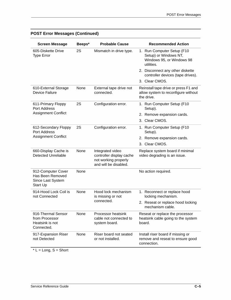
POST Error Messages
605-Diskette Drive Type Error
2S Mismatch in drive type. 1. Run Computer Setup (F10 Setup) or Windows NT, Windows 95, or Windows 98 utilities.
2. Disconnect any other diskette controller devices (tape drives).
3. Clear CMOS.
610-External Storage Device Failure
None External tape drive not connected.
Reinstall tape drive or press F1 and allow system to reconfigure without the drive.
611-Primary Floppy Port Address Assignment Conflict
2S Configuration error. 1. Run Computer Setup (F10 Setup).
2. Remove expansion cards.
3. Clear CMOS.
612-Secondary Floppy Port Address Assignment Conflict
2S Configuration error. 1. Run Computer Setup (F10 Setup).
2. Remove expansion cards.
3. Clear CMOS.
660-Display Cache is Detected Unreliable
None Integrated video controller display cache not working properly and will be disabled.
Replace system board if minimal video degrading is an issue.
912-Computer Cover Has Been Removed Since Last System Start Up
None No action required.
914-Hood Lock Coil is not Connected
None Hood lock mechanism is missing or not connected.
1. Reconnect or replace hood locking mechanism.
2. Reseat or replace hood locking mechanism cable.
916-Thermal Sensor from Processor Heatsink is not Connected.
None Processor heatsink cable not connected to system board.
Reseat or replace the processor heatsink cable going to the system board.
917-Expansion Riser not Detected
None Riser board not seated or not installed.
Install riser board if missing or remove and reseat to ensure good connection.
* L = Long, S = Short
POST Error Messages (Continued)
Screen Message Beeps* Probable Cause Recommended Action
Service Reference Guide C–5

POST Error Messages
1151-Serial Port 1 Address Conflict Detected
2S Both external and internal serial ports are assigned to COM1.
1. Remove any Comm port expansion cards.
2. Clear CMOS.
3. Reconfigure card resources and/or run Computer Setup (F10 Setup). Run Computer Setup or Windows utilities.
1152-Serial Port 2 Address Conflict Detected
2S Both external and internal serial ports are assigned to COM2.
1. Remove any Comm port expansion cards.
2. Clear CMOS.
3. Reconfigure card resources and/or run Computer Setup (F10 Setup). Run Computer Setup or Windows utilities.
1155- Serial Port Address Conflict Detected
2S Both external and internal serial ports are assigned to same IRQ.
1. Remove any Comm port expansion cards.
2. Clear CMOS.
3. Reconfigure card resources and/or run Computer Setup (F10 Setup).Run Computer Setup or Windows utilities.
1201-System Audio Address Conflict Detected
2S Device IRQ address conflicts with another device.
Reset the IRQ.
1202-MIDI Port Address Conflict Detected
2S Device IRQ address conflicts with another device.
Reset the IRQ.
1203-Game Port Address Conflict Detected
Device IRQ address conflicts with another device.
Reset the IRQ
1611- Fan failure detected
None Chassis fan not connected to the system board.
1. Reconnect the fan.
2. Replace the fan.
3. Replace the system board.
* L = Long, S = Short
POST Error Messages (Continued)
Screen Message Beeps* Probable Cause Recommended Action
C–6 Service Reference Guide

POST Error Messages
1720-SMART Hard Drive Detects Imminent Failure
None Hard drive is about to fail. (Some hard drives have a firmware patch that will fix an erroneous error message.)
1. Determine if hard drive is giving correct error message. Run the Drive Protection System test available.
2. Apply firmware patch if applicable (see www.compaq.com\support\techpubs\customer_advisories).
3. Back up contents and replace hard drive.
1721-SMART SCSI Hard Drive Detects Imminent Failure
None Hard drive is about to fail. (Some hard drives have a firmware patch that will fix an erroneous error message.)
1. Determine if hard drive is giving correct error message. Run the Drive Protection System test available.
2. Apply firmware patch if applicable.
3. Back up contents and replace hard drive.
1771-Primary Disk Port Address Assignment Conflict
2S Internal and external hard drive controllers are both assigned to the primary address.
1. Remove any disk controller expansion cards.
2. Clear CMOS.
3. Reconfigure card resources and/or run Computer Setup (F10 Setup).
1772-Secondary Disk Port Address Assignment Conflict
2S Internal and external hard drive controllers are both assigned to the primary address.
1. Remove any disk controller expansion cards.
2. Clear CMOS.
3. Reconfigure card resources and/or run Computer Setup (F10 Setup).
1780-Disk 0 Failure None Hard drive/format error. 1. Run Computer Setup (F10 Setup).
2. Clear CMOS.
3. Check cables/jumper settings.
4. Run hard drive diagnostics.
5. Disconnect additional drives.
6. Run the Drive Protection System test if available.
7. Replace the hard drive.
* L = Long, S = Short
POST Error Messages (Continued)
Screen Message Beeps* Probable Cause Recommended Action
Service Reference Guide C–7

POST Error Messages
1781-Disk 1 Failure None Hard drive/format error. 1. Run Computer Setup (F10 Setup).
2. Clear CMOS.
3. Check cable seating/jumper settings.
4. Run hard drive diagnostics.
5. Disconnect additional drives.
6. Run the Drive Protection System test if available.
7. Replace the hard drive.
1782-Disk Controller Failure
None Hard drive circuitry error.
1. Run Computer Setup (F10 Setup).
2. Clear CMOS.
3. Check cable seating /jumper settings.
4. Run hard drive diagnostics.
5. Disconnect additional drives.
6. Run the Drive Protection System test if available.
7. Check www.compaq.com\support\ techpubs\customer_advisories for possible changes when using Windows NT4.0 Service Pack 4.
8. Replace the hard drive.
9. Replace the system board.
* L = Long, S = Short
POST Error Messages (Continued)
Screen Message Beeps* Probable Cause Recommended Action
C–8 Service Reference Guide

POST Error Messages
1790-Disk 0 Failure None Hard drive error or wrong drive type.
1. Run Computer Setup (F10 Setup).
2. Clear CMOS.
3. Check cable seating /jumper settings.
4. Run hard drive diagnostics.
5. Disconnect additional drives.
6. Confirm that drive is supported on this computer (large drive ROM support).
7. Run the Drive Protection System test if available.
8. Replace the hard drive.
9. Replace the system board.
1791-Disk 1 Failure None Hard drive error or wrong drive type.
1. Run Computer Setup (F10 Setup).
2. Clear CMOS.
3. Check cable seating /jumper settings.
4. Run hard drive diagnostics.
5. Disconnect additional drives.
6. Confirm that drive is supported on this computer (l arge drive ROM support).
7. Run the Drive Protection System test if available.
8. Replace the hard drive.
9. Replace the system board.
1792-Secondary Disk Controller Failure
None Hard drive circuitry error.
1. Run Computer Setup (F10 Setup).
2. Clear CMOS.
3. Check cable seating /jumper settings.
4. Run hard drive diagnostics.
5. Disconnect additional drives.
6. Run the Drive Protection System test if available.
7. Replace the hard drive.
* L = Long, S = Short
POST Error Messages (Continued)
Screen Message Beeps* Probable Cause Recommended Action
Service Reference Guide C–9

POST Error Messages
1793-Secondary Controller or Disk Failure
None Hard drive circuitry error.
1. Run Computer Setup (F10 Setup).
2. Clear CMOS.
3. Check cable seating /jumper settings.
4. Run hard drive diagnostics.
5. Disconnect additional drives.
6. Run the Drive Protection System test if available.
7. Replace the hard drive.
1800-Temperature Alert
None Internal temperature exceeds specification.
1. Check that computer air vents are not blocked and cooling fan is running.
2. Verify processor speed selection.
3. Replace the processor.
4. Replace the system board.
1801-Microcode Patch Error
None Processor not supported by ROM BIOS.
Upgrade BIOS to proper version.
Audible 1L, 3S System ROM is bad; system is running in Failsafe Boot Block mode.
Reflash the ROM using a ROMPaq diskette. Refer to the "Failsafe Boot Block ROM" section of the Software Reference Guide.
Audible 2S Power-on successful. None.
Fixed Disk Parameter Table or BIOS Error System Halted
3L Configuration or hardware failure.
Run Computer Setup and Diagnostic Utilities.
Flashing Caps Lock LED on Keyboard
1L, 2S Graphics controller not present or incorrectly initialized.
1. Clear CMOS.
2. If graphics card has been added, remove and reseat.
3. Reset the riser board.
Flashing Num Lock LED on Keyboard (Most models. Blue LED glows on Professional Workstation 800.)
1S, 2L System memory not present.
1. Check memory module.
2. Remove and reseat memory module.
3. See "Memory" in Appendix F.
* L = Long, S = Short
POST Error Messages (Continued)
Screen Message Beeps* Probable Cause Recommended Action
C–10 Service Reference Guide

POST Error Messages
Flashing Power and Hard Drive Green LEDs (Most models. Blue LED glows on Professional Workstation 800.)
None Unseated riser board. 1. Remove riser board.
2. Wipe connector with a dry, clean cloth.
3. Reinstall riser board.
Flashing Scroll Lock LED on Keyboard (Most models. Orange LED glows on Professional Workstation 800)
2L, 1S System board hardware failure (prior to video).
Replace system board.
Green Power LED Blinks Once per Second
None Computer in normal Suspend mode.
None.
Green Power LED ON None Computer on. None.
Invalid Electronic Serial Number
None Electronic serial number has become corrupted.
1. Run Computer Setup (F10 Setup). If Setup already has data in the field or will not allow the serial number to be entered, download and run SP5572.EXE (SNZERO.EXE).
2. Run F10 Setup and try to enter serial number under Security, System ID, then save changes.
Num Lock LED on Keyboard
None Failed Boot Block. Reflash the ROM using a ROMPaq diskette.
Red Power LED Blinks Every 2 or More Seconds
None Power supply overloaded.
1. Push in power button. LED should be green.
2. Remove all AC power from computer, wait 30 seconds, then apply power.
3. Remove load from power supply by removing options one at a time until computer runs.
4. Check for damage to system board.
5. Replace system board.
6. Replace power supply.
* L = Long, S = Short
POST Error Messages (Continued)
Screen Message Beeps* Probable Cause Recommended Action
Service Reference Guide C–11
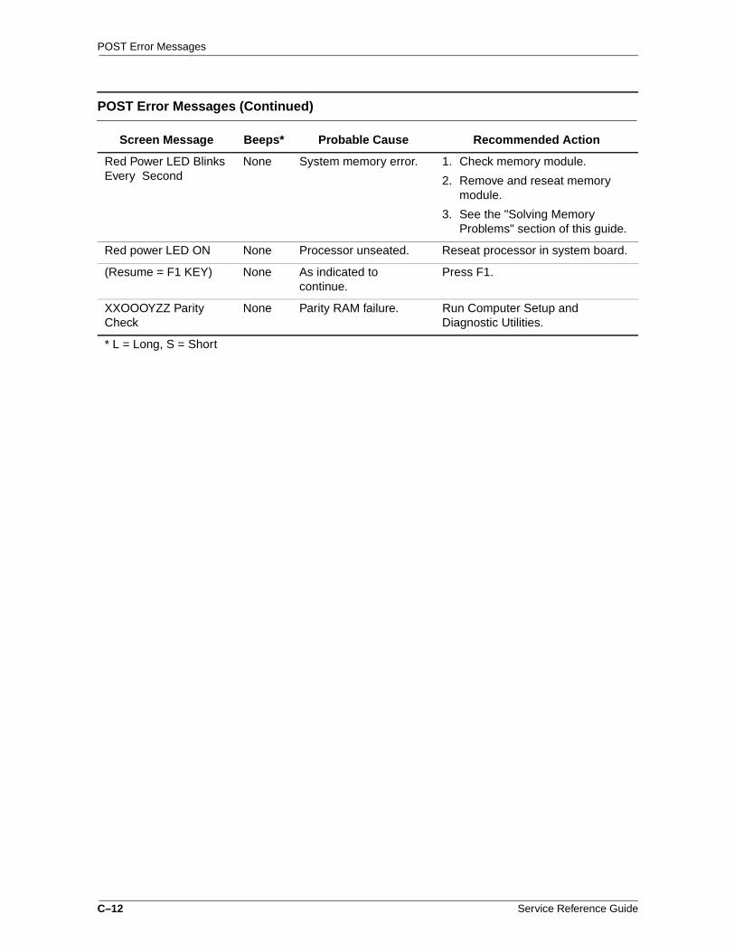
POST Error Messages
Red Power LED Blinks Every Second
None System memory error. 1. Check memory module.
2. Remove and reseat memory module.
3. See the "Solving Memory Problems" section of this guide.
Red power LED ON None Processor unseated. Reseat processor in system board.
(Resume = F1 KEY) None As indicated to continue.
Press F1.
XXOOOYZZ Parity Check
None Parity RAM failure. Run Computer Setup and Diagnostic Utilities.
* L = Long, S = Short
POST Error Messages (Continued)
Screen Message Beeps* Probable Cause Recommended Action
C–12 Service Reference Guide
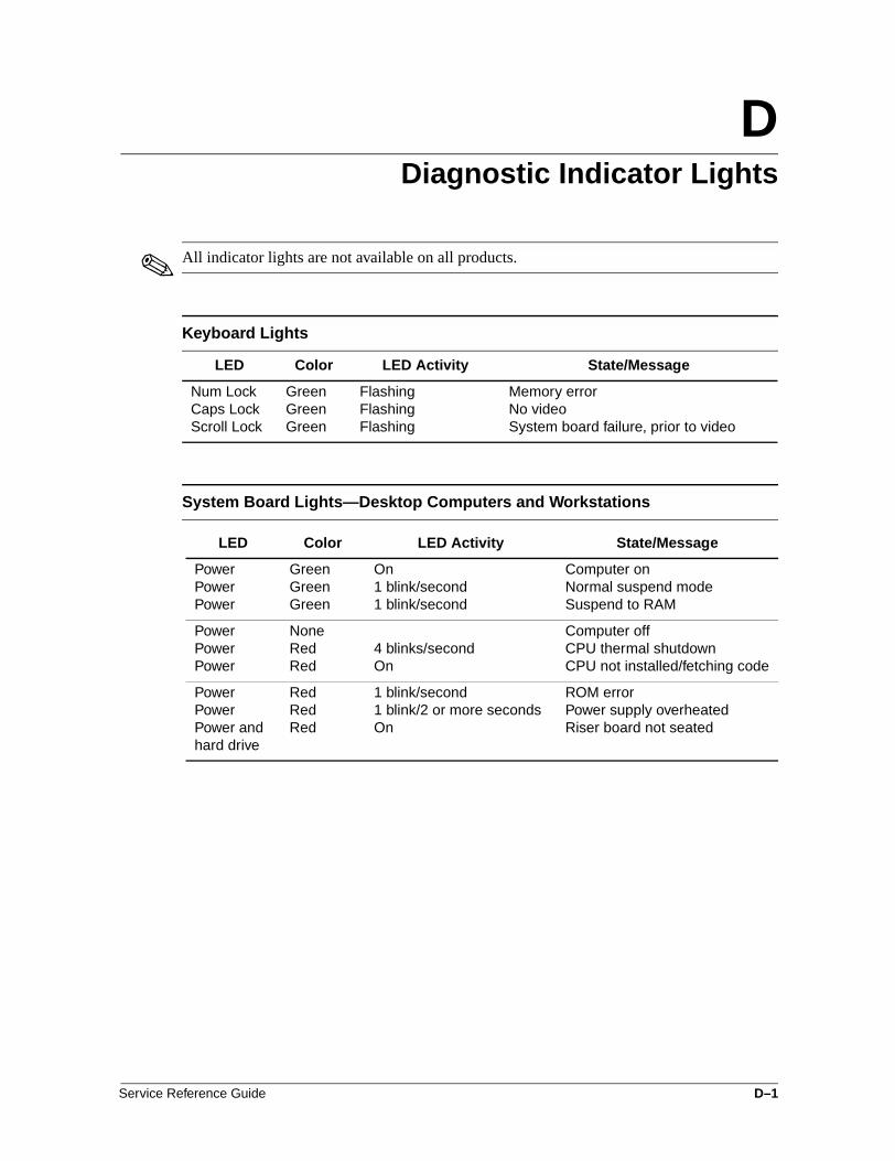
DDiagnostic Indicator Lights
✎ All indicator lights are not available on all products.
Keyboard Lights
LED Color LED Activity State/Message
Num LockCaps LockScroll Lock
GreenGreenGreen
Flashing FlashingFlashing
Memory errorNo videoSystem board failure, prior to video
System Board Lights—Desktop Computers and Workstations
LED Color LED Activity State/Message
PowerPowerPower
GreenGreenGreen
On1 blink/second1 blink/second
Computer onNormal suspend modeSuspend to RAM
PowerPowerPower
NoneRedRed
4 blinks/secondOn
Computer offCPU thermal shutdownCPU not installed/fetching code
PowerPowerPower and hard drive
RedRedRed
1 blink/second1 blink/2 or more secondsOn
ROM errorPower supply overheatedRiser board not seated
Service Reference Guide D–1

D–2 Service Reference Guide

EDiagnostic Error Codes
Diagnostic error codes occur if the system recognizes a problem while running the Compaq Diagnostics program. These error codes help identify possibly defective subassemblies.
Diagnostic error messages consist of three components, AABB-CC, where
AA = Device Code
BB = Subtest Code
CC = Error Code
The following table lists the device codes (AABB-CC) and the subtest code (AABB-CC) covered by Compaq Diagnostics Tests. Some codes listed in this table will not apply to the computers described in this manual and will not be detailed in the tables that follow.
Summary of Test Error Codes
Error Code Range Device Description
Error Code Range Device Description
0100 - 01990200 - 02100301 - 03040401 - 0498
Processor (P1)MemoryKeyboardParallel Port
3113 - 31993206 - 32063300 - 3333
Third Processor (P3)Audio SystemMediavision Spectrum 16Multimedia
0501 - 05160600 - 06990802 - 08241101 - 1109
Video Display UnitDiskette DriveMonochrome Video CardSerial Port
3400 - 34014113 - 41995100 - 51305234 - 5240
TV Tuner Card FourthProcessorPlasma Display SystemAdvanced Color Graphics (AGC)
1201 - 12101700 - 17991800 - 18231900 - 1906
ModemHard DriveCD-ROMTape Drive
6000 - 60896500 - 65996600 - 66996700 - 6799
Network CardSCSI Hard DrivesCD-ROM DrivesSCSI Tape Drives
2113 - 21992402 - 2480
2502
Second Processor (P2)Enhanced Color Graphics (ECG/VGA)Pen/Digitizer
700086018700 - 8702
Server Manager/R CardAuxiliary Input InterfaceGame Port
Service Reference Guide E–1

Diagnostic Error Codes
The remaining tables list possible error codes (AABB-CC), descriptions of each error condition, and recommended actions to resolve the error condition.
✎ Retest the system after completing each step. If the problem has been resolved, do not proceed with the remaining steps.
For assistance in the removal and replacement of a particular subassembly, see the "Removal and Replacement Procedures" chapter in the product-specific MSG.
Microprocessor
Error Code Description Recommended Action
0101-xx CPU test failed. The following steps apply to 0101-xx through 0102-xx:
0102-xx Coprocessor error. 1. Run Computer Checkup or Computer Setup and retest.
2. Replace processor and retest.
3. Replace the system board and retest.
0103-xx DMA controller failed. The following step applies to 0103-xx through 0106-xx:
0104-xx Interrupt controller failed. Replace the system board and retest.
0105-xx Port error.
0106-xx Keyboard controller self-test failed.
0107-xx CMOS RAM test failed. The following steps apply to 0107-xx through 0109-xx:
0108-xx CMOS interrupt test failed. 1. Replace the battery/clock module and retest.
0109-xx CMOS clock test failed. 2. Replace the system board and retest.
0110-xx Programmable timer test failed.
Replace the system board and retest.
0113-01 Protected mode test failed. Replace the system board and retest.
0114-01 Speaker test failed. 1. Verify the speaker connection.
2. Replace speaker (if applicable) and retest.
3. Replace the system board and retest.
0199-xx Installed devices test failed. 1. Check system configuration.
2. Verify cable connections.
3. Check switch settings.
4. Run Diagnostics utility.
5. Remove all devices except processor and replace one-at-a-time until a failure occurs.
6. Replace the system board.
E–2 Service Reference Guide

Diagnostic Error Codes
✎ Holding any key down during the boot-up sequence causes the Basic Input Output System (BIOS) to beep, as a warning of possible keyboard problems. Wait until after the system has booted, then press the Num Lock key. If the Num Lock light on the keyboard toggles on and off with each press of the key, the keyboard is functioning properly.
Memory
Error Code Description Recommended Action
0200-xx Machine ID test failed. Reinsert memory modules and retest.
0202-xx System ROM checksum failed.
The following steps apply to 0202-xx through 0212-xx:
0203-xx Write/read test failed. 1. Remove one memory module at a time until the error message stops.
0204-xx Address test failed. 2. Replace other removed modules one at a time, testing each to ensure the error does not return.
0205-xxx Walking 1s test failed. 3. Replace defective modules.
0209-xxx RAM long test failed. 4. If error continues, replace system board and retest.
0211-xx Random pattern test failed.
0212-xxx Cache test failed.
0214-xx Noise test failed. The following steps apply to 0214-xx through 0215-xx:
0215-xx Random address test failed. 1. Remove one memory module at a time until the error message stops.
2. Replace other removed modules one at a time, testing each to ensure the error does not return.
3. Replace the system board and retest.
Keyboard
Error Code Description Recommended Action
0300-xx ID test failed. The following steps apply 0300-xx through 0304-xx:
0301-xx Self-test/interface test failed. 1. Check the keyboard connection. If disconnected, turn the computer off and connect the keyboard.
0302-xx Individual key test failed. 2. Replace the keyboard and retest.
0304-xx Repeat test failed. 3. Replace the system board and retest.
Service Reference Guide E–3

Diagnostic Error Codes
Parallel Port
Error Code Description Recommended Action
0401-xx Failed or not connected. The following steps apply to 0401-xx through 0403-xx:
0402-xx Printer port test failed. 1. Connect the printer.
0403-xx Pattern test failed. 2. Check power to the printer.
3. Install the loop-back connector and retest.
4. Replace system board and retest.
Diskette Drive
Error Code Description Recommended Action
0600-xx ID drive types test failed. The following steps apply to 0600-xx through 0698-xx:
0601-xx Format failed. 1. Replace the diskette media and retest.
0602-xx Read test failed. 2. Reseat and/or replace the diskette power and signal cables and retest.
0603-xx Write, read, compare test failed.
3. Replace the diskette drive and retest.
0604-xx Random seek test failed. 4. Replace the system board and retest.
0605-xx ID media test failed.
0606-xx Speed test failed.
0609-xx Diskette reset controller failed.
0610-xx Change line test failed.
0697-xx Diskette type error.
0698-xx Diskette drive speed not within limits.
0699-xx Diskette drive/media error. 1. Replace the diskette media and retest.
2. Run Computer Setup and TEST.
E–4 Service Reference Guide

Diagnostic Error Codes
Serial Port
Error Code Description Recommended Action
1101-xx Serial port test failed. 1. Run Computer Setup or Windows NT, Windows 98/2000/ME utilities.
2. Replace the system board and retest.
Modem Communications
Error Code Description Recommended Action
1201-xx Internal test failed. The following steps apply to 1201-xx through 1210-xx:
1203-xx External termination test failed.
1. Disconnect from the phone line and retest.
1204-xx Auto originate test failed. 2. Check the phone number.
1205-xx Auto answer test failed. 3. Check the modem line.
1210-xx Direct connect test failed. 4. Replace the modem and retest.
Service Reference Guide E–5

Diagnostic Error Codes
Hard Drive
Error Code Description Recommended Action
1701-xx Format test failed. The following steps apply to 1701-xx through 1736-xx:
1702-xx Read test failed. 1. Run Computer Setup and verify drive type.
1703-xx Write/read/compare test failed.
2. Reseat or replace the hard drive signal and power cables and retest.
1704-xx Random seek test failed. 3. Clear CMOS.
1705-xx Controller test failed. 4. Run the hard drive DPS test.
1708-xx Format bad track test failed. 5. Replace the hard drive and retest.
1710-xx Park head test failed. 6. Replace the system board and retest.
1715-xx Head select test failed.
1716-xx Conditional format test failed.
1717-xx ECC* test failed.
1719-xx Power mode test failed.
1724-xx Network preparation test failed.
1736-xx Monitoring test failed.
*Error Correction Code
Tape Drive
Error Code Description Recommended Action
1900-xx ID test failed. The following steps apply to 1900-xx through 1910-xx
1901-xx Servo test failed. 1. Replace the tape cartridge and retest.
1902-xx Format or format verification test failed.
2. Reseat and/or replace the signal cable and retest.
1903-xx Sensor test failed. 3. Check the switch settings on the adapter card (if applicable).
1904-xx BOT/EOT test failed. 4. Replace the tape adapter card (if applicable) and retest.
1905-xx Read test failed. 5. Replace the tape drive and retest.
1906-xx Write/read/compare failed. 6. Replace the system board and retest.
1910-xx Tape erase test failed.
E–6 Service Reference Guide

Diagnostic Error Codes
Video
Error Code Description Recommended Action
501-xx Graphics controller test failed. The following steps apply to 501-xx through 516-xx:
502-xx Video memory test failed. 1. Replace the monitor and retest.
503-xx Video attribute test failed. 2. Replace the graphics controller and retest.
504-xx Video character test failed. 3. Replace the system board and retest.
505-xx Video 80 × 25 mode 9 × 14 character cell test failed.
506-xx Video 80 × 25 mode 8 × 8 character cell test failed.
507-xx Video 40 × 25 mode test failed.
508-xx Video 300 × 200 mode color set 0 test failed.
509-xx Video 320 × 200 mode color set 1 test failed.
510-xx Video 640 × 200 mode test failed.
511-xx Video screen memory page test failed.
512-xx Video gray scale test failed.
514-xx Video white screen test failed.
516-xx Video noise pattern test failed.
2401-xx Graphics controller test failed. 1. Reseat the video card (if applicable) and retest.
2. Replace the video card and retest.
3. Replace the system board and retest.
2402-xx Memory test failed. The following steps apply to 2402-xx through 2419-xx:
2403-xx Attribute test failed. 1. Reseat the video card (if applicable) and retest.
2404-xx Character set test failed. 2. Run the Configuration and Diagnostics utilities.
2405-xx 80 × 25 mode 9 × 14 character cell test failed.
3. Replace the monitor and retest.
2406-xx 80 × 25 mode 8 × 8 character cell test failed.
4. Replace the video/system board and retest.
2408-xx 320 × 200 mode color set 0 test failed.
Service Reference Guide E–7

Diagnostic Error Codes
2409-xx 320 × 200 mode color set 1 test failed.
2410-xx 640 × 200 mode test failed.
2411-xx Screen memory page test failed.
2412-xx Gray scale test failed.
2418-xx ECG/VGC memory test failed.
2419-xx ECG/VGC ROM checksum test failed.
2420-xx Graphics attribute test failed. Replace the monitor and retest.
2421-xx ECG/VGC 640 × 200 graphics mode test failed.
1. Reseat the video card (if applicable) and retest.
2. Replace the video/system board and retest.
2422-xx ECG/VGC 640 × 350 16 color set test failed.
The following steps apply to 2422-xx through 2456-xx:
2423-xx ECG/VGC 640 × 350 64 color set test failed.
1. Reseat the video card (if applicable) and retest.
2424-xx ECG/VGC monochrome text mode test failed.
2. Run the Configuration and Diagnostics utilities.
2425-xx ECG/VGC monochrome graphics mode test failed.
3. Replace the monitor and retest.
2431-xx 640 × 480 graphics test failed. 4. Replace the video/system board and retest
2432-xx 320 × 200 graphics (256 color mode) test failed.
2448-xx Advanced VGA Controller test failed.
2451-xx 132-column Advanced VGA test failed.
2456-xx Advanced VGA 256 Color test failed.
2458-xx Advanced VGA BitBLT test. The following steps apply to 2458-xx through 2480-xx:
2468-xx Advanced VGA DAC test. 1. Reseat the video card (if applicable) and retest.
2477-xx Advanced VGA data path test. 2. Replace the video card and retest.
2478-xx Advanced VGA BitBLT test. 3. Replace the system board and retest.
2480-xx Advanced VGA Linedraw test.
Video (Continued)
Error Code Description Recommended Action
E–8 Service Reference Guide

Diagnostic Error Codes
Audio
Error Code Description Recommended Action
3206-xx Audio System Internal Error. Replace the system board and retest.
✎ When Windows 98/2000/ ME is installed, changes to ESS sound device configuration do not take effect until the computer is restarted (turned off and on).
Network Interface
Error Code Description Recommended Action
6000-xx ID test failed. The following steps apply to 6000-xx through 6089-xx:
6014-xx Configuration test failed.* 1. Run Computer Setup or Windows NT, Windows 95, 98, 2000, or ME utilities.
6016-xx Reset test failed.* 2. Verify test procedures.
6028-xx Internal test failed.* 3. Replace the network card, if installed.
6029-xx External test failed.* 4. Replace the system board.
6054-xx Configuration test failed.**
6056-xx Reset test failed.**
6068-xx Internal test failed.**
6069-xx External test failed.**
6089-xx Open test failed.**
* Ethernet only.**Token Ring only.
CD-ROM and DVD-ROM
Error Code Description Recommended Action
3301-xx CD-ROM drive read test failed.
The following steps apply to 3301-xx through 3305-xx and 6600-xx through 6623-xx:
3305-xx CD-ROM drive seek test failed.
1. Replace the CD media and retest.
6600-xx ID test failed. 2. Check the jumper settings on the adapter card.
6605-xx Read test failed. 3. Verify that the speakers are connected.
6608-xx Controller test failed. 4. Reseat and/or replace the power and signal cables and retest.
6623-xx Random read test failed. 5. Replace the CD-ROM drive and retest.
Service Reference Guide E–9
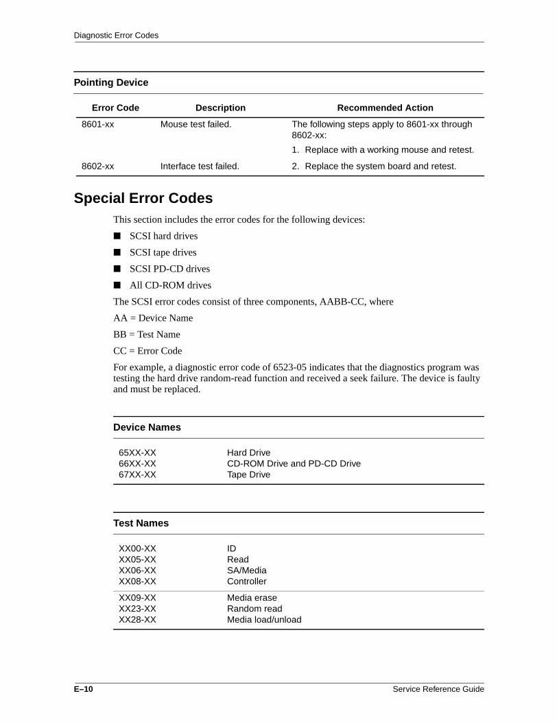
Diagnostic Error Codes
Special Error CodesThis section includes the error codes for the following devices:
■ SCSI hard drives
■ SCSI tape drives
■ SCSI PD-CD drives
■ All CD-ROM drives
The SCSI error codes consist of three components, AABB-CC, where
AA = Device Name
BB = Test Name
CC = Error Code
For example, a diagnostic error code of 6523-05 indicates that the diagnostics program was testing the hard drive random-read function and received a seek failure. The device is faulty and must be replaced.
Pointing Device
Error Code Description Recommended Action
8601-xx Mouse test failed. The following steps apply to 8601-xx through 8602-xx:
1. Replace with a working mouse and retest.
8602-xx Interface test failed. 2. Replace the system board and retest.
Device Names
65XX-XX66XX-XX67XX-XX
Hard DriveCD-ROM Drive and PD-CD DriveTape Drive
Test Names
XX00-XXXX05-XXXX06-XXXX08-XX
IDReadSA/MediaController
XX09-XXXX23-XXXX28-XX
Media eraseRandom readMedia load/unload
E–10 Service Reference Guide
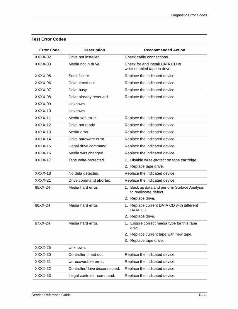
Diagnostic Error Codes
Test Error Codes
Error Code Description Recommended Action
XXXX-02 Drive not installed. Check cable connections.
XXXX-03 Media not in drive. Check for and install DATA CD or write-enabled tape in drive.
XXXX-05 Seek failure. Replace the indicated device.
XXXX-06 Drive timed out. Replace the indicated device.
XXXX-07 Drive busy. Replace the indicated device.
XXXX-08 Drive already reserved. Replace the indicated device.
XXXX-09 Unknown.
XXXX-10 Unknown.
XXXX-11 Media soft error. Replace the indicated device.
XXXX-12 Drive not ready. Replace the indicated device.
XXXX-13 Media error. Replace the indicated device.
XXXX-14 Drive hardware error. Replace the indicated device.
XXXX-15 Illegal drive command. Replace the indicated device.
XXXX-16 Media was changed. Replace the indicated device.
XXXX-17 Tape write-protected. 1. Disable write-protect on tape cartridge.
2. Replace tape drive.
XXXX-18 No data detected. Replace the indicated device.
XXXX-21 Drive command aborted. Replace the indicated device.
65XX-24 Media hard error. 1. Back up data and perform Surface Analysis to reallocate defect.
2. Replace drive.
66XX-24 Media hard error. 1. Replace current DATA CD with different DATA CD.
2. Replace drive.
67XX-24 Media hard error. 1. Ensure correct media type for this tape drive.
2. Replace current tape with new tape.
3. Replace tape drive.
XXXX-25 Unknown.
XXXX-30 Controller timed out. Replace the indicated device.
XXXX-31 Unrecoverable error. Replace the indicated device.
XXXX-32 Controller/drive disconnected. Replace the indicated device.
XXXX-33 Illegal controller command. Replace the indicated device.
Service Reference Guide E–11

Diagnostic Error Codes
XXXX-34 Invalid SCSI bus phase. Replace the indicated device.
XXXX-35 Invalid SCSI bus phase. Replace the indicated device.
XXXX-36 Invalid SCSI bus phase. Replace the indicated device.
XXXX-39 Error status from drive. Replace the indicated device.
XXXX-40 Target timed out. Replace the indicated device.
XXXX-41 SCSI bus stayed busy. Replace the indicated device.
XXXX-42 ACK/REQ lines bad. Replace the indicated device.
XXXX-43 ACK did not deassert. Replace the indicated device.
XXXX-44 Parity error. Replace the indicated device.
XXXX-50 Data pins bad. Replace the indicated device.
XXXX-51 Data line 7 bad. Replace the indicated device.
XXXX-52 MSG, C/D, and/or I/O lines bad.
Replace the indicated device.
XXXX-53 BSY never went busy. Replace the indicated device.
XXXX-54 BSY stayed busy. Replace the indicated device.
XXXX-60 Controller CONFIG-1 register bad
Replace the indicated device.
XXXX-61 Controller CONFIG-2 register bad
Replace the indicated device.
XXXX-65 Media not unloaded. Replace the indicated device.
XXXX-90 Fain failure. 1. Ensure fan(s) connected.
2. Replace nonfunctional fan(s).
XXXX-91 Over temperature. 1. Ensure proper air flow.
2. Perform required maintenance and cleaning.
XXXX-99 Autoloader reported tapes not loaded properly.
1. Install tape(s) in autoloader tape drive according to test instructions.
2. Change autoloader magazine.
Test Error Codes (Continued)
Error Code Description Recommended Action
E–12 Service Reference Guide

FTroubleshooting Without Diagnostics
Preliminary ChecklistThis section describes some simple, preliminary tests and guidelines for troubleshooting the computer without using the diagnostics.
If you encounter some minor problem with the computer or a software application, go through the following checklist for possible solutions before running any of the diagnostic utilities:
■ Are the computer and monitor connected to a working electrical outlet?
■ Is the computer turned on?
■ Is the green power light illuminated?
■ Is the monitor turned on?
■ Is the green monitor light illuminated?
■ Turn up the monitor brightness and contrast controls if the monitor is dim.
■ Press and hold any key. If the system beeps, then the keyboard is operating correctly.
■ Check all cables for loose or incorrect connections.
■ Reconfigure the computer after installing a non–Plug and Play expansion board or other option, such as a diskette drive.
■ Are all of the necessary device drivers installed?
■ Have all printer drivers been installed for each application?
■ Remove all diskettes from the diskette drives before you turn on the system.
■ Are all switches set correctly?
■ Is the NIC Remote Wakeup cable (featured on some models) connected between the NIC and the riser/system board?
■ Are all memory sockets filled on computers using RIMMs?
■ Ensure that memory module types are not mixed on the same system board. The system will not boot if RIMMs and DIMMs are mixed.
Service Reference Guide F–1

Troubleshooting Without Diagnostics
Solving Minor Problems
Problem Possible Solution
Computer will not turn on. 1. Ensure that the computer is properly connected to an external power source and the wall outlet is active.
2. A PCI or ISA card that has been installed is defective. Remove any expansion card that was just installed.
3. Reseat drive power, data, and power supply cables.
4. Disconnect all drive cables and reboot. Add devices back one at a time to isolate problem.
Computer appears locked up and won’t turn off when the power button is pressed.
Software control of the power button may not be functional. Press and hold the button for four seconds, then release. This invokes the hardware override for the power button.
Computer date and time display is incorrect.
First, reset the date and time under Control Panel. If the problem persists, the real-time clock (RTC) battery may need to be replaced. Refer to Section 9.1 in this guide. When booting from a network, the PC clock may be reset to that of the server. The PC clock may also change when using other services through the server.
Computer powered off automatically. 1. The unit temperature was exceeded because the unit is in an exceedingly hot environment or the fan is blocked. Let the unit cool down.
2. The fan may not be functioning correctly or the air vents are blocked.
3. The unit temperature was exceeded because the computer was functioning with the cover or side panel removed. Replace cover or side panel, and let the computer cool down.
4. The unit temperature was exceeded because the air baffle is not properly installed to directir flow over the processor.
Insufficient power to the components. Ensure that both power supply cables are connected to the system board (on some workstations).
Computer appears to pause periodically
Network driver is loaded and no network connection is established. Establish a network connection, or use Computer Setup or Windows Device Manager to disable the network controller.
Cannot remove computer cover or side panel.
1. Smart Lock, featured on some computers, is locked. Unlock the Smart Cover Lock using Computer Setup.
2. The Smart Cover FailSafe Key, a device for manually disabling the Smart Cover Lock, is available from Compaq. You need the FailSafe Key in cases of forgotten password, power loss, or computer malfunction.
F–2 Service Reference Guide

Troubleshooting Without Diagnostics
Computer does not boot up and power and hard drive LEDs are blinking.
Ensure that the riser board is properly seated.
Computer does not boot up and Num Lock LED is blinking; you may hear one short and two long beeps.
Memory may be improperly installed or may be bad.
The Caps Lock LED is flashing;you may hear one long and two short beeps.
The video controller is not present or is incorrectly initialized. Clear configuration memory (CMOS). If a video card has been added, remove and reseat it.
Computer does not boot up and the Scroll Lock LED is flashing; you may hear two long and one short beeps.
System board hardware failure (prior to video). Replace system board.
✎ If the standard keyboard has been replaced with a Universal Serial Bus (USB) keyboard, you will hear the beep sequences mentioned above but will not see the flashing lights.
Solving Minor Problems (Continued)
Problem Possible Solution
Service Reference Guide F–3

Troubleshooting Without Diagnostics
Diskette Drive
Problem Possible Solution
Diskette drive light stays on. 1. Diskette is damaged. In Windows 98, 2000, or Me run ScanDisk. Click Start > Programs > Accessories > System Tools > ScanDisk.In Windows NT, right–click Start, click Explore, and select a drive. Select File > Properties > Tools. Under Error-checking, click Check Now.
2. Diskette is incorrectly inserted. Remove the diskette and reinsert.
3. Software program may be damaged. Check the program diskettes.
4. Drive button is not pushed in. Push in drive button.
5. Drive cable is not properly connected. Reconnect drive cable.
Diskette drive cannot write to a diskette.
1. Diskette is not formatted. Format the diskette.
2. Diskette is write-protected. Either use another diskette that is not write-protected or disable the write protection on the diskette.
3. Writing to the wrong drive. Check the drive letter in the path statement.
4. Not enough space is left on the diskette. Use another diskette.
5. Diskette write control is enabled. Check the Removable Media write settings in Computer Setup.
Cannot format diskette. Invalid media reported. When formatting a diskette in DOS, you may need to specify diskette capacity. For example, to format a 1.44-MB diskette, type the following command at the DOS prompt:FORMAT A: /F:1440
Diskette drive cannot read a diskette. 1. Diskette is not formatted. Format the diskette.
2. Using the wrong diskette type for the drive type. Check the drive type and use a compatible diskette.
3. Reading the wrong drive. Check the drive letter in the path statement.
4. Diskette drive has been disabled by Computer Setup, Windows NT, Windows 98, 2000 or Me utilities. Run Computer Setup and enable the diskette drive.
F–4 Service Reference Guide

Troubleshooting Without Diagnostics
A problem has occurred with a disk transaction.
The directory structure is bad, or there is a problem with a file. In Windows 98, 2000, or Me run ScanDisk. Click Start > Programs > Accessories > System Tools > ScanDisk.
In Windows NT, right–click Start, click Explore, and select a drive. Select File > Properties > Tools. Under Error-checking, click Check Now.
Non-system disk message. The system is trying to start from a nonsystem diskette. Remove the diskette from the drive.
Drive not found. 1. Reseat the diskette drive cable.
2. If a second diskette drive has been installed, follow the computer reconfiguration directions in the "Hardware Installation Problems" section.
System has misidentified the diskette drive type.
If a diskette drive other than a 3.5-inch, 1.44-MB drive has been installed, ensure that the drive type is identified correctly under Computer Setup.
Diskette Drive (Continued)
Problem Possible Solution
Service Reference Guide F–5
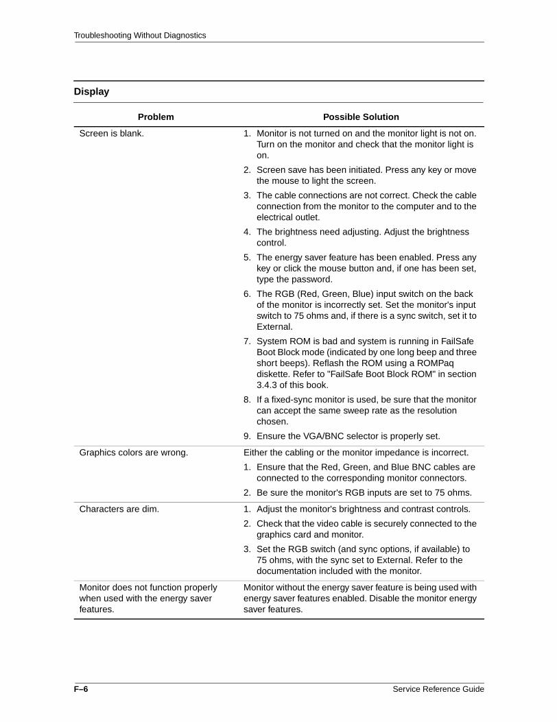
Troubleshooting Without Diagnostics
Display
Problem Possible Solution
Screen is blank. 1. Monitor is not turned on and the monitor light is not on. Turn on the monitor and check that the monitor light is on.
2. Screen save has been initiated. Press any key or move the mouse to light the screen.
3. The cable connections are not correct. Check the cable connection from the monitor to the computer and to the electrical outlet.
4. The brightness need adjusting. Adjust the brightness control.
5. The energy saver feature has been enabled. Press any key or click the mouse button and, if one has been set, type the password.
6. The RGB (Red, Green, Blue) input switch on the back of the monitor is incorrectly set. Set the monitor's input switch to 75 ohms and, if there is a sync switch, set it to External.
7. System ROM is bad and system is running in FailSafe Boot Block mode (indicated by one long beep and three short beeps). Reflash the ROM using a ROMPaq diskette. Refer to "FailSafe Boot Block ROM" in section 3.4.3 of this book.
8. If a fixed-sync monitor is used, be sure that the monitor can accept the same sweep rate as the resolution chosen.
9. Ensure the VGA/BNC selector is properly set.
Graphics colors are wrong. Either the cabling or the monitor impedance is incorrect.
1. Ensure that the Red, Green, and Blue BNC cables are connected to the corresponding monitor connectors.
2. Be sure the monitor's RGB inputs are set to 75 ohms.
Characters are dim. 1. Adjust the monitor's brightness and contrast controls.
2. Check that the video cable is securely connected to the graphics card and monitor.
3. Set the RGB switch (and sync options, if available) to 75 ohms, with the sync set to External. Refer to the documentation included with the monitor.
Monitor does not function properly when used with the energy saver features.
Monitor without the energy saver feature is being used with energy saver features enabled. Disable the monitor energy saver features.
F–6 Service Reference Guide

Troubleshooting Without Diagnostics
Blurry display or requested resolution cannot be set.
If the graphics controller was upgraded, the correct display drivers may not be loaded. Install the correct display drivers from the diskette included in the upgrade kit.
The picture is broken up; it rolls, jitters, or blinks.
1. Be sure the monitor cable is securely connected to the computer.
2. In a two-monitor system or if another monitor is in close proximity, move the monitors apart to be sure they are not interfering with the other's magnetic field.
3. Fluorescent lights or fans may be too close to the monitor.
Screen goes blank. A screen blanking utility may be installed or energy saver features may be enabled. Press any key or type password.
Monitor overheats. There is not enough ventilation space for proper airflow. Leave at least 3 inches (7.6 cm) of ventilation space. Be sure there is nothing on top of the monitor obstructing the air flow.
Cursor will not move using the arrow keys on the numeric keypad.
The Num Lock key is on. Press the key to turn it off. The Num Lock light should not be on when you want to use the arrow keys.
Display (Continued)
Problem Possible Solution
SCSI
Problem Possible Solution
System with IDE and SCSI drives will not boot from SCSI hard drive.
The IDE drive needs to be disabled. Under the Computer Setup Advanced menu, disable the primary IDE controller.
System will not boot from a SCSI drive.
1. The SCSI drive is not configured correctly.
2. Ensure that drive cabling and jumpers are set correctly. To boot a SCSI drive, the drive ID number must be set to 0.
Service Reference Guide F–7

Troubleshooting Without Diagnostics
Printer
Problem Possible Solution
Printer will not print. 1. Printer is not turned on and online. Turn the printer on and ensure it is online.
2. Run printer self-test.
3. Reseat both ends of the printer cable.
4. Verify that printer port is enabled in BIOS and in Windows using F10 Setup.
5. Try printing using the DOS command C:\ [printer port]. Where [printer port] is the port address to which the printer is connected. If the printer works, the problem is with the printer driver. Reload the driver.
6. If the computer is on a network, you may not have made the connection to the printer. Make the proper network connections to the printer.
Printer will not turn on. The cables may not be connected properly. Reconnect all cables and check the power cord and electrical outlet.
Prints garbled information. 1. The correct printer driver for the application are not installed. Install the correct printer driver for the application.
2. The cables may not be connected properly. Reconnect all cables.
Printer is offline. The printer may be out of paper. Check the paper tray and refill it if empty. Select online.
F–8 Service Reference Guide
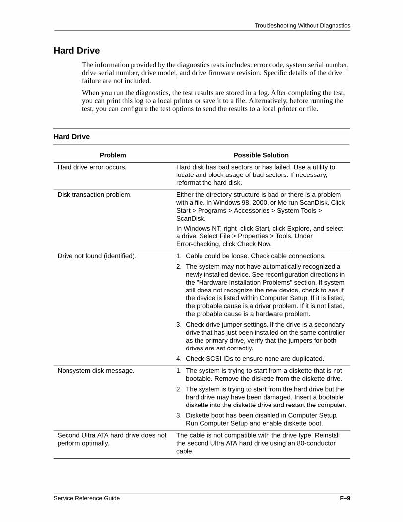
Troubleshooting Without Diagnostics
Hard Drive
The information provided by the diagnostics tests includes: error code, system serial number, drive serial number, drive model, and drive firmware revision. Specific details of the drive failure are not included.
When you run the diagnostics, the test results are stored in a log. After completing the test, you can print this log to a local printer or save it to a file. Alternatively, before running the test, you can configure the test options to send the results to a local printer or file.
Hard Drive
Problem Possible Solution
Hard drive error occurs. Hard disk has bad sectors or has failed. Use a utility to locate and block usage of bad sectors. If necessary, reformat the hard disk.
Disk transaction problem. Either the directory structure is bad or there is a problem with a file. In Windows 98, 2000, or Me run ScanDisk. Click Start > Programs > Accessories > System Tools > ScanDisk.
In Windows NT, right–click Start, click Explore, and select a drive. Select File > Properties > Tools. Under Error-checking, click Check Now.
Drive not found (identified). 1. Cable could be loose. Check cable connections.
2. The system may not have automatically recognized a newly installed device. See reconfiguration directions in the "Hardware Installation Problems" section. If system still does not recognize the new device, check to see if the device is listed within Computer Setup. If it is listed, the probable cause is a driver problem. If it is not listed, the probable cause is a hardware problem.
3. Check drive jumper settings. If the drive is a secondary drive that has just been installed on the same controller as the primary drive, verify that the jumpers for both drives are set correctly.
4. Check SCSI IDs to ensure none are duplicated.
Nonsystem disk message. 1. The system is trying to start from a diskette that is not bootable. Remove the diskette from the diskette drive.
2. The system is trying to start from the hard drive but the hard drive may have been damaged. Insert a bootable diskette into the diskette drive and restart the computer.
3. Diskette boot has been disabled in Computer Setup. Run Computer Setup and enable diskette boot.
Second Ultra ATA hard drive does not perform optimally.
The cable is not compatible with the drive type. Reinstall the second Ultra ATA hard drive using an 80-conductor cable.
Service Reference Guide F–9

Troubleshooting Without Diagnostics
Audio
Problem Possible Solution
Sound does not come out of the speaker.
Software volume control is turned down electronically, or CD-ROM volume control on the front or back of the computer is turned down. Double–click on the speaker icon located on the taskbar, then set the volume by adjusting the volume slider.
CD or DVD volume control on the front of the computer may be turned down. Increase the volume by turning the volume control dial.
External speakers not turned on. Turn on the speakers.
External speakers plugged into wrong jacks. Refer to the Computer User’s Guide or sound card documentation for proper speaker connection.
Audio cable not connected. Connect audio cable between CD or DVD drive and the system board.
Noise or silence comes from the speakers or headphones.
Computer may not detect correct speaker/headphone type or output or analog–to–digital auto–sense is not engaged.
1. If using digital speakers with a stereo jack, use the stereo–to–mono adapter to engage the auto–sense feature.
2. If a the stereo–to–mono adapter is not available, use the multimedia device properties to manually switch the audio signal from analog to digital.
3. If the headphones have a mono jack, use the multimedia device properties to manually switch the system to analog out.
✎ If you set digital as the Output mode, the internal speaker and external analog speakers will no longer output audio until you switch back to an auto–sense or analog mode.If you set analog as your Output Mode, external digital speakers will not function until you change the output mode back to auto–sense or digital mode.
F–10 Service Reference Guide

Troubleshooting Without Diagnostics
Hardware Installation
You may need to reconfigure the computer when you add or remove hardware, such as an additional diskette drive. If you install a Plug and Play device, Windows 98, 2000, or Me in most cases will automatically recognize the device and configures the computer. If a third-party Plug and Play device is not recognized, contact the device manufacturer. If you install a non–Plug and Play device, you must reconfigure the computer after completing installation of the new hardware. In Windows 98, 2000, or Me, select the Add New Hardware icon in the Control Panel and follow the instructions that appear on the screen. To reconfigure the computer in Windows NT Workstation 4.0 after installing new hardware, use the utility provided with the hardware..
Hardware Installation
Problem Possible Solutions
A new device is not automatically recognized as part of the computer system.
1. The computer needs to be reconfigured to recognize the new device. Follow the reconfiguration instructions above. If system still does not recognize the new device, but the device is listed within Computer Setup, use Computer Setup to address any resource conflicts.
2. When the system advised you of changes to the configuration, you did not accept them. Reboot the computer and follow the instructions for accepting the changes.
3. A Plug and Play board may not automatically configure when added if the default configuration conflicts with other devices. Use Windows 98, 2000, or Me Device Manager to deselect the automatic settings for the board and choose a basic configuration that doesn’t cause a resource conflict. You can also use Computer Setup to reconfigure or disable devices to resolve the resource conflict.
4. The cables for the new external device are loose or the power cables are unplugged. Check all cables, and check that pins in the cable or connector are not bent down.
5. The power switch for the new external device is not turned on. Turn off the computer, turn on the external device, and then turn the computer on to integrate the new device with the computer.
6. If the drive is a secondary drive that has just been installed on the same controller as the primary drive, verify that the jumpers for both drives are set correctly.
Insufficient power to the components.
Ensure both power supply cables are connected to the system board (some Workstations).
Installed third-party SCSI hard drive adapter not participating in the hard drive ordering sequence provided in F10 Setup and/or is always coming up as the boot device regardless of the predetermined sequence.
The third-party adapter is either not supporting BIOS Boot Specification or the Boot Vector option. A solution is not available.
Service Reference Guide F–11

Troubleshooting Without Diagnostics
DVD-ROM and CD-ROM
Problem Possible Solution
Cannot read compact disc. 1. CD is not properly seated in the drive. Eject the CD, correctly seat it in the drive, then reload.
2. CD has been loaded upside down. Eject the CD, turn it over, then reload.
System will not boot from CD-ROM or DVD drive.
1. The CD-ROM or DVD boot is not enabled through the Computer Setup utility. Run the Computer Setup utility and set the drive priorities.
2. Ensure that drive cabling and jumpers are set correctly. To boot a SCSI drive, the drive ID number must be set to 0.
Cannot eject compact disc (tray-load unit).
CD is not properly seated in the drive. Turn off the computer and insert a thin metal rod into the emergency eject hole and push firmly (a straightened paper clip can be used). Slowly pull the tray out from the drive until the tray is fully extended, then remove the CD.
Cannot eject compact disc (slot-load unit).
1. Remove the drive from the chassis.
2. Remove the front bezel from the drive.
3. Remove the top and bottom drive covers.
4. Release the clamping mechanism to retrieve the CD.
CD-ROM or DVD device is not detected; driver is not loaded.
CD-ROM or DVD drive is not connected properly or not properly terminated. Open the computer and check the drive cable.
Movie will not play in the DVD drive. Movie may be regionalized for a different country. Refer to the documentation that came with the device.
Processor
Problem Possible Solution
Computer does not recognize the second processor.
Hardware Abstract Layer (HAL) installed is for a single processor. Install the multi-processor HAL.
F–12 Service Reference Guide

Troubleshooting Without Diagnostics
Memory
Problem Possible Solution
System won't boot or does not function properly after installing additional memory modules.
Memory module is not the correct type or speed grade for the system. Replace module with the correct industry-standard device for the computer.
Out of Memory error. 1. Memory configuration may not be set up correctly; check memory configuration using Device Manager.
2. The computer has run out of memory for the application. Check the application documentation to determine the memory requirements.
Memory count during POST is wrong. Memory modules may not have been installed correctly or incorrect modules may have been used.
✎ On system boards having integrated Intel video that use 1 MB of memory for video it is normal for POST to have the memory count 1 MB short.
Insufficient memory error during operation.
1. Too many Terminate and Stay Resident programs (TSRs) are installed. Delete any unnecessary TSRs.
2. There is not enough memory for the application. Check the memory requirements for the application or add more memory.
Unit is on but there is no video and the power LED is blinking red.
Memory is not installed correctly and system is not booting. Reinstall memory modules.
Service Reference Guide F–13

Troubleshooting Without Diagnostics
Network
Some common causes and solutions for network problems are listed in the following table. These guidelines do not discuss the process of debugging network cabling.
Network
Problem Possible Solution
The Remote Wakeup feature is not functioning.
1. The feature is not available when using an AUI network connection; use an RJ-45 network connection.
2. Remote Wakeup is not enabled. Use the network control application to enable Remote Wakeup.
Network driver does not detect network controller.
Network controller is disabled. Run Computer Setup and enable network controller.
Network status link light does not turn on or flashes.
1. No active network is detected. Check cabling and network equipment for proper connection.
2. Network connection is not set up properly. Use the network control application to verify that the device is working properly.
3. System is configured for AUI connection; link LED does not apply to AUI connections.
4. Network driver is not properly loaded. Reinstall network drivers.
5. System cannot autosense the network. Disable autosensing capabilities and force the system into the correct operating mode.
Diagnostics reports a failure. Refer to www.compaq.com/support/files for the latest version of diagnostics.
1. The cable is not securely connected or is attached incorrectly. Ensure that the cable is securely attached to the network connector and that the other end of the cable is securely attached to the correct device.
2. There is a problem with the cable or a device at the other end of the cable. Ensure that the cable and device at the other end are operating correctly.
3. The network controller is defective. Replace the controller or the system board.
4. Network controller interrupt is shared with an expansion board. Under the Computer Setup Advanced menu, change the resource settings for the board.
F–14 Service Reference Guide

Troubleshooting Without Diagnostics
Diagnostics passes, but the computer does not communicate with the network.
1. Network drivers are not loaded, or driver parameters do not match current configuration. Make sure the network drivers are loaded and the driver parameters match the configuration of the network controller.
2. The network controller is not configured for this computer. In Windows 98/2000/Me/Windows NT, select the Network icon at the Control Panel.
3. Network controller interrupt with an expansion board. Under the Computer Setup Advanced menu, change the resource settings for the board.
Network controller stopped working when an expansion board was added to the computer.
1. Network drivers are not loaded or driver parameters do not match the current configuration. Make sure that the drivers are loaded and that the driver parameters match the configuration of the network controller.
2. The cable is not securely connected or is attached incorrectly. Ensure that the cable is securely attached to the network connector and that the other end of the cable is securely attached to the correct device.
3. Network controller interrupt is shared with an expansion board. Under the Computer Setup Advanced menu, change the resource settings for the board.
4. Network drivers were accidentally deleted when the drivers for the new expansion board were installed, or the files containing the network drivers are corrupted. Reinstall the network drivers, using backup diskettes.
Network controller stopped working without apparent cause.
1. The files containing the network drivers are corrupted. Reinstall the network drivers, using backup diskettes or the Compaq Restore CD.
2. The cable is not securely connected or is attached incorrectly. Ensure that the cable is securely attached to the network connector and that the other end of the cable is securely attached to the correct device.
3. The network controller is defective. Replace the network controller or system board.
Cannot connect to the network server when attempting Remote System Installation.
The network controller is not configured properly. Run Computer Setup and modify the Embedded NIC Settings.
System Setup utility reports unprogrammed EPROM.
1. Boot the workstation without the network drivers using a system boot diskette and reconfigure the controller.
2. Replace the controller.
3. Replace the system board.
Network (Continued)
Problem Possible Solution
Service Reference Guide F–15

Troubleshooting Without Diagnostics
Resolving Audio Hardware Conflicts
Hardware conflicts occur when two or more peripheral devices contend for the same signal lines or channels. Conflicts between the audio interface and another peripheral device may be due to the settings of the base I/O addresses, interrupts, or DMA channels. The audio interface typically has the following settings:
To resolve hardware conflicts:
1. Change the hardware settings of your audio card or the peripheral card in your system if the peripheral card is using the audio interface setting. You can change settings for integrated audio using Computer Setup.
2. If you are unsure of the settings of the peripheral cards, you can isolate the source of the problem by temporarily removing all cards and other essential cards such as the disk controller. After that, add the cards back one at a time until the card that is causing the conflict is found.
Troubleshooting Using Compaq IntelligentManageability Features
The Local Alert Pop-Up Dialog notifies you of an impending or actual hardware failure. If the computer is connected to a network and the Compaq Insight Management Agents are installed and configured, a Simple Network Management Protocol (SNMP) trap (message) is sent to the specified SNMP-compliant management application.
The Local Alert Pop-Up Dialog also tells you the steps you need to take prior to a hardware failure to avoid loss of data and damage to the computer. The system administrator can create a customized action message that might include contact telephone or pager numbers.
To close the Local Alert Pop-Up Dialog, click the Close button. To retrieve fault information after closing the dialog, run Compaq Insight Personal Edition.
For more detailed information, refer to the online Intelligent Manageability Guide.
Item Setting
Base I/O adressFM Synthesizer I/O addressInterrupt8-bitDMA
220H388-38BhIRQ 5Channel 1
F–16 Service Reference Guide
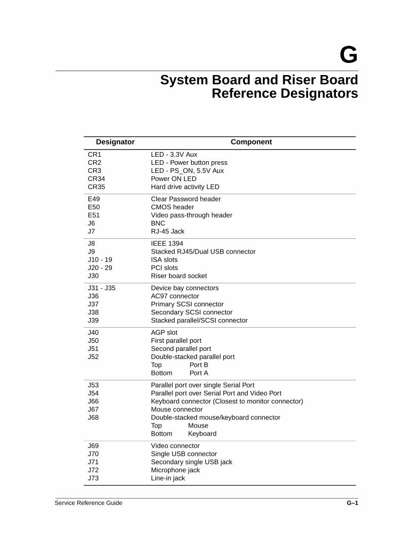
GSystem Board and Riser Board
Reference Designators
Designator Component
CR1CR2CR3CR34CR35
LED - 3.3V AuxLED - Power button pressLED - PS_ON, 5.5V AuxPower ON LEDHard drive activity LED
E49E50E51J6J7
Clear Password headerCMOS headerVideo pass-through headerBNCRJ-45 Jack
J8J9J10 - 19J20 - 29J30
IEEE 1394Stacked RJ45/Dual USB connectorISA slotsPCI slotsRiser board socket
J31 - J35J36J37J38J39
Device bay connectorsAC97 connectorPrimary SCSI connectorSecondary SCSI connectorStacked parallel/SCSI connector
J40J50J51J52
AGP slotFirst parallel portSecond parallel portDouble-stacked parallel portTop Port BBottom Port A
J53J54J66J67J68
Parallel port over single Serial PortParallel port over Serial Port and Video PortKeyboard connector (Closest to monitor connector)Mouse connectorDouble-stacked mouse/keyboard connectorTop MouseBottom Keyboard
J69J70J71J72J73
Video connectorSingle USB connectorSecondary single USB jackMicrophone jackLine-in jack
Service Reference Guide G–1

System Board and Riser Board Reference Designators
J74J75J76J77
Line-out jackHeadphone jackVolume controlDouble-stacked headphone/microphone connectorTop MicrophoneBottom Headphone
J78
J80
Double-stacked line-in/line-out connectorTop Line inBottom Line outStacked serial/audio connector
J81
J82
Primary double-stack USBTop Port 2Bottom Port 1Secondary double-stack USBTop Port 4Bottom Port 3
J83J113P1P2P3
Triple-stacked audio jack (line in, line out/headphone, microphone)Video cache connectorP/S connectorSecond P/S connector (as required)Third P/S connector (as required)
P5
P6P7P8
Main Power switch and HDD and power LED connector (pins 1-9) and SCSI LED connector (pins 10-11)Speaker connectorAudio connector (from CD-ROM)Chassis fan connector
P9P10P11P12P15
WOL connector (NIC cable)Diskette drive connectorSecond Audio connectorAlert on LAN NIC connectorAUI connector
P20P21P22P23P24
Primary IDE connectorSecondary IDE (Multibay) connectorSlimline CD-ROM connectorHeader for front audio panelHeader for front panel USB
P25 - P26P27P29P53P54
Video memory upgrade connectorMultiBay headerSCSI LED connectorFirst serial portSecond serial port
P55
P58P70
Double stack serial portTop Serial BBottom Serial ARiser edge connector (male-mates with J30)Processor (CPU) fan header for fansink
Designator Component (Continued)
G–2 Service Reference Guide

System Board and Riser Board Reference Designators
P71P89P100P120P124
Secondary CPU fan header for fansinkFloating serial port /COM port headerITP connectorSecondary chassis fan headerHood lock header
P125P216SW1SW2SW50
Hood sensor headerWhite box chassis fanProcessor speed switchSecurity hood switchClear CMOS switch
SW51XBT1XMM1XMM2 - XMM5XU1
Power button switchBattery socketMemory slot. DIMM1 or RIMM1 populated and testedFollowing memory slotsPrimary processor socket
XU2XU15
Secondary processor socketROM socket
Designator Component (Continued)
Service Reference Guide G–3

System Board and Riser Board Reference Designators
G–4 Service Reference Guide

HModel Number Naming
for Compaq Products
Compaq Deskpro Series of Personal Computers
ProductLineEN, EP,EC, EX
END/P933/10a/6/128c/vmB
Form FactorC - Convertible
MinitowerD - Desktop (DT)Ds - DT SMBL - Slim DesktopM - Minitower (MT)Ms - MT SMBm - MicrotowerS - Small Form
FactorT - Tower
Processor TypeC - CeleronP - Pentium
ProcessorSpeed,MHz (NNN)andGHz (N.N)
Hard DriveCapacity,GB
Chipset Typeblank - BX d - 820a - 810 e - 815eb - 810e f - 850c - 815 h - lite e
OperatingSystem2 - Win 20004 - Win NT 4.05 - Win 956 - 2+48 - Win 989 - 5+8m - Win ME
RemovableStorageblank - noneb - c+rc - CD-ROMd - DVDr - CDRWz - ZIP
Memory,MB RAM
Nic/Modemn - NICm - modem
Graphicsblank -
integrateda - AIMMv - nVidia1 - nM64 16 MB3 - nM64 32 MB5 - NV158 - nVanta 8 MB
SMB SoftwareB - Office 2000
Small BusinessF - Office 2000
ProfessionalP - Office 2000
PremiumW - MS WordS - Office 2000
Personal
Slash exists only when numberof characters permits use
Service Reference Guide H–1

Model Number Naming for Compaq Products
Compaq iPAQ Desktop Personal Computers
iPAQ -Legacy Free
iPAQL -Legacy Lite
iPAQL/P733/10b/2/128c
ProcessorSpeed,MHz
Chipsetb - 810ee - 815e
Hard DriveCapacity,GB
Removable Storageblank - no driveb - c + rc - CD-ROMd - DVDr - CDRWs - SuperDiskz - ZIP
Processor TypeC - CeleronP - Pentium
Memory,MB Ram
OperatingSystem2 - Win 20004 - Win NT 4.05 - Win 956 - 2 + 48 - Win 989 - 5 + 8
H–2 Service Reference Guide

Model Number Naming for Compaq Products
Compaq Deskpro and Professional Workstations
Processors 1.0 GHz and Greater
D - DeskproWorkstationP - ProfessionalWorkstationD25 - 250D30 - 300P55 - 550P60 - 600P75 - 750P80 - 800
P60/1.0+/40S+/256/2+d
ProcessorSpeed, GHz
Hard Drive Size9 - 9.1 GB
18 - 18.2 GB20 - 20 GB
Graphics2 - 2D2+ - 2D/3D3M - Mid 3D3E - Enh. 3D2X - multi 2 port4X - multi 4 portX - no graphics
Memory,MB RAM
Hard DriveTypeS - SCSIA - UATA
Optical Devicec - CD-ROMd - DVD-ROMr - CDRW
2ndProcessor
2ndHardDrive
Service Reference Guide H–3

Model Number Naming for Compaq Products
H–4 Service Reference Guide

Index
4-, 14-, 20-, 24-pin power pin assignments A–12Aaccess panel, removal and replacement 7–9access to components without baffle removal 9–7additional documentation 2–xAGP card
pin assignments A–9retention mechanism 8–23with Type 1 mechanism, removal and
replacement 8–25with Type 2 retention mechanism, removal
and replacement 8–27air baffle type 1, removal and replacement 9–8air baffle type 2, removal and replacement 9–9air flow 2–xAltiris eXpress 3–3AssetControl 3–3
Bbattery
proper disposal 9–2board guide, removal and replacement 9–13broken key icon 3–6Building Blocks and Partners 3–21
Ccable
multi-mode SCSI 5–2SCSI adapter 5–1
cable lockKensington 7–7provision 3–11type 1 7–4type 2 7–5
cable select drive 4–1card guide, removal and replacement 9–13caution symbols 2–ixcautions
AC power 7–1, 9–1, 10–1AC power source 6–1adding devices 1–1air baffle 9–7batteries 6–6cable placement 8–1cable routing 5–1cables 6–6, 7–1, 7–9, 10–1
Compaq Restore CD 1–4computer chassis 7–14cooling fan 6–5, 7–1, 7–2, 7–9drivelock spring 10–14GPA/AIMM card 8–24guide screws 8–3installation 1–1installing RIMMs 8–14, 8–15memory installation 8–19memory sockets 8–12power cord 7–9processor 10–1subpanel 7–21, 10–18
CD-ROM drivedevice sequence 4–1jumper positions 5–5
chain termination, SCSI 5–2chipset
440BX 8–12810/810e 8–12815e 8–13820 8–14850 8–15
cleaningkeyboard 6–4monitor 6–4mouse 6–5
Compaq Deskpro Supplement CD 2–13Compaq Diagnostics for Windows 2–12Compaq Drive Protection System 3–12Compaq Insight Manager LC 3–3, 3–12, 3–13Compaq Restore CD 1–3, 2–13, 2–14Compaq Restore CD for Windows NT 2–14Compaq software. See softwarecomponent access without baffle removal 9–7computer
cleaning 6–4cover, removal and replacement 7–10diagnostics 2–9registration 1–4security features 3–3
Computer Checkup (TEST) 2–9Computer Setup
menu 2–4replicating 3–19utilities 2–2
Service Reference Guide Index–1

configuration of RIMMs 8–14, 8–15, 8–17connector pin assignments A–1 to A–12conventions and symbols 2–ixconvertible desktop to minitower conversion
10–17convertible minitower, drive removal and
replacement 8–2convertible minitower, drivelock removal 10–14country-specific power cord set requirements
B–2CRIMMs
install in empty RIMM sockets 8–14, 8–15removal and replacement 8–17
Ddelimiter characters 3–7deployment, remote 3–3desk attachment, iPAQ 7–14Desktop Management Interface (DMI) 3–21desktop, converting to minitower 10–17desktop, slim
diskette drive, removal and replacement 8–6drive removal and replacement 8–5hard drive, removal and replacement 8–7
desktop, standardhard drive removal and replacement 8–8
device 0/device 1 relationship 4–3device drivers
installing/upgrading 1–1, 1–2obtaining 1–5SCSI 1–2
device sequence, all drives 4–1diagnostic
diskette 2–9error codes E–1indicator lights D–1tests 2–13
diagnostics, computer 2–9DIMMs, removal and replacement 8–16disassembly preparation 7–1diskette emergency repair 1–3documentation 2–xdrive
adapter, removal and replacement 8–4cable select 4–3capacities 4–3device designation 4–1partition size 4–3removal and replacement 8–1repartition 1–3
drivelock, horizontal, reinstalling 10–16drivelock, removal and replacement 10–14DVD-ROM drive
device sequence 4–1jumper positions 5–5
Eelectrostatic discharge. See ESDemergency repair diskette 1–3error checking and correcting (ECC)
fault prediction 3–13prefailure warranty 3–13
error codes, diagnostic E–1error codes, test
audio E–9CD-ROM/DVD-ROM E–9diskette drive E–4hard drive E–6keyboard E–3memory E–3microprocessor E–2modem communications E–5network interface E–9parallel port E–4pointing device E–10serial port E–5special E–10summary E–1tape drive E–6video E–7
ESD (electrostatic discharge)information 6–1materials and equipment 6–3preventing damage 6–2
EthernetAUI pin assignments A–2BNC pin assignments A–1RJ-45 pin assignments A–2
expansion card cage, removal and replacement 8–20
expansion card, removal and replacement 8–22
FFailSafe
beeps 3–16Boot Block ROM 3–16key 3–9recovery 3–16
fanpower supply 6–5standard, removal and replacement 9–5
Index–2 Service Reference Guide

with cover, removal and replacement 9–6FAT 32 to NTFS conversion 1–4fault prediction 3–12feet, removal and replacement 7–15Fingerprint Identification Technology 3–124-pin power pin assignments A–1214-pin power pin assignments A–10, A–11front bezel, removal and replacement 7–16front trim, removal and replacement 7–23
GGPA/AIMM card with Type 2 mechanism,
removal and replacement 8–26graphics card, removal and replacement 8–23,
8–24graphics memory cache replacement 8–29grounding methods 6–2
Hhard drive latch, Slim Desktop
removal and replacement 10–19hard drive, proper handling 6–6Hardware Application Layer (HAL) 10–10headphone pin assignments A–4heatsink
dual clip removal 10–12removal and replacement 10–10
heatsink, roundremoval and replacement 10–13
heatsink, single clipremoval and replacement 10–11
hood sensor, removal and replacement 7–13horizontal drivelock, reinstalling 10–16
Iicon, broken key 3–6ID numbers, SCSI 5–1IDE CD-ROM pin assignments A–10IDE/EIDE drive cable pin assignments A–7infrared (IR) transceiver, external, pin
assignments A–6INSPECT 2–11installation
combining Zip and DVD drives 4–2drive guidelines 4–2
Intelligent Manageability, defined 3–1interior access panel, iPAQ 7–12iPAQ
desk attachment 7–14exterior access panel 7–11front bezel removal 7–18
graphics memory cache replacement 8–29hard drive, removal and replacement 8–11interior access panel 7–12legacy module replacement 8–30MultiBay board replacement 8–31speaker grill replacement 7–20system board replacement 10–5top bezel replacement 7–19
IR transceiver. See infrared (IR) transceiver
Jjumper positions
CD-ROM drive 5–5DVD-ROM drive 5–5SCSI hard drive 5–4Zip drive 5–5
KKensington cable lock 7–7key, FailSafe 3–9keyboard
cleaning 6–4delimiter characters 3–7indicator lights D–1light combinations 3–17pin assignments A–1
Llegacy module removal and replacement 8–30lights, indicator D–1line-in audio pin assignments A–4line-out audio pin assignments A–4LS-120 drive, device sequence 4–1
MManagement Setup Utilities 3–3Master Boot Record Security
disabling 3–11enabling 3–10
memoryCRIMM installation 8–17DIMM installation 8–16expansion 8–12installation 8–19installation guidelines 8–14, 8–15RIMM installation 8–17
microphone pin assignments A–4model number naming convention
Compaq Deskpro H–1Compaq Deskpro and Professional
Workstations 1-GHz+ H–3Compaq iPAQ H–2
Service Reference Guide Index–3

monitorcleaning 6–4pin assignments A–6
mousecleaning 6–5pin assignments A–1
MultiBay board, iPAQ, removal and replacement 8–31
Nnational keyboard delimiter characters 3–7network service boot 3–2NIC Alert 3–19NTFS, converting to 1–3
Pparallel interface pin assignments A–3password
changing 3–6clearing 3–7deleting 3–7entering 3–6establishing 3–5, 3–6power-on 3–5
PC Transplant 3–3POST (Power-On Self-Test) 2–3POST error messages C–1 to C–12power button
dual state 3–19removal and replacement (CMT) 7–22
power cord set requirementscountry specific B–2general B–1
power management, setting timeouts 3–20power supply
fan 6–5removal and replacement 10–7
power switchsecured with screws, removal and replacement
9–10secured with tabs
Type 1, removal and replacement 9–11Type 2, removal and replacement 9–12
power-on password 3–5Power-On Self-Test (POST) 2–3prefailure warranty 3–12preinstalled software 3–2processor
recognizing second 10–10removal and replacement 10–9
Rrecognizing second processor 10–10registration, computer 1–4Remote Management Setup Utilities 3–13, 3–14Remote Security Management 3–18remote system installation 3–2Remote Wakeup and Shutdown 3–18removal and replacement
access panel 7–9AGP card with Type 1 mechanism 8–25AGP card with Type 2 retention mechanism
8–27air baffle 9–8, 9–9board guide 9–13card guide 9–13computer cover 7–10convertible minitower drives 8–2CRIMMs 8–17DIMMs 8–16drive adapter 8–4drivelock, convertible minitower 10–14drives 8–1expansion card 8–22expansion card cage 8–20fan
standard 9–5with cover 9–6
feet 7–15front bezel 7–16front bezel, iPAQ 7–18front trim 7–23GPA/AIMM card with Type 2 mechanism
8–26graphics card 8–23graphics memory cache, iPAQ 8–29heatsink 10–10
dual clip 10–12single clip 10–11
hood sensor 7–13horizontal drivelock 10–16iPAQ
speaker 9–4iPAQ desk attachment 7–14iPAQ exterior access panel 7–11legacy module, iPAQ 8–30MultiBay board, iPAQ 8–31power button (CMT) 7–22power supply 10–7power switch secured with screws 9–10
Index–4 Service Reference Guide

power switch secured with tabsType 1 9–11Type 2 9–12
processor 10–9RIMMs 8–17riser board 8–21side-mounted hard drive 8–8slim desktop diskette drive 8–6slim desktop drives 8–5slim desktop hard drive 8–7small form factor drives 8–5speaker 9–3speaker grill, iPAQ 7–20speaker, iPAQ 9–4standard desktop diskette drive 8–10standard desktop external drive 8–9standard desktop hard drive 8–8subpanel and bezel blanks 7–21system board with screws 10–1top bezel, iPAQ 7–19
repartition, drive 1–3required tools and software 6–5retention mechanism, AGP 8–23RIMMs
configuration guidelines 8–14, 8–15, 8–18dual memory channel system 8–18installation 8–17, 8–19removal and replacement 8–17single memory channel system 8–17
riser boarddesignators G–1removal and replacement 8–21
ROM flashlocal 3–14remote 3–15
Sscrews, correct size 6–5SCSI
cable adapter 5–1chain termination 5–2device drivers 1–2guidelines 5–1ID numbers 5–1jumper positions 5–4multi-mode cable 5–2pin assignments A–5
SCSISelect utility 5–3second processor recognition 10–10security
bar, iPAQ 7–3devices 7–2features, computer 3–3
serial interface pin assignments A–3service considerations 6–5setup 1–1
password 3–5software 1–5windows 1–1
side-mounted hard drive, removal and replacement 8–8
slim desktopdiskette drive, removal and replacement 8–6drive removal and replacement 8–5hard drive latch removal and replacement
10–19hard drive, removal and replacement 8–7
slimline CD-ROM adapter pin assignments A–8small form factor
drive removal and replacement 8–5system board removal and replacement 10–3
Smart CoverFailSafe key 3–9
spare part number 7–2lock 3–8lock, unlocking 7–2locking 3–9sensor protection level 3–8unlocking 3–9
SMART drive 4–3, 5–3hard drive fault prediction 3–12
softwareAltiris eXpress 3–3AssetControl 3–3Compaq Deskpro Supplement CD 2–13Compaq Diagnostics for Windows 2–12Compaq Drive Protection System 3–12Compaq Insight Manager LC 3–3, 3–12, 3–13Compaq Restore CD 2–13, 2–14Compaq Restore CD for Windows NT 2–14Computer Setup Utilities 2–1Insight Manager LC 3–3Management Setup Utilities 3–3ordering 2–14PC Transplant 3–3protecting 2–13recovery 2–14Remote Management Setup Utilities 3–14remote system installation 3–2required 6–5
Service Reference Guide Index–5

SCSISelect utility 5–3setup 1–5System Software Manager 3–13updating 3–13
spare part numberSmart Cover FailSafe key 7–2
speakergrill removal and replacement, iPAQ 7–20iPAQ, removal and replacement 9–4removal and replacement 9–3
standard desktopdiskette drive, removal and replacement 8–10external drive, removal and replacement 8–9hard drive removal and replacement 8–8
static electricity 6–1subpanel and bezel blanks, removal and
replacement 7–21symbols and conventions 2–ixsymbols in text 1–iisymbols, warning 2–ixsystem board
designators G–1general guidelines 10–1indicator lights D–1removal and replacement
iPAQ 10–5removal and replacement, small form factor
10–3removal and replacement, with screws 10–1
system installation, remote 3–2System Software Manager 3–13
Ttape drive, device sequence 4–1technician notes 2–xTEST (Computer Checkup) 2–9test error codes
audio E–9CD-ROM/DVD-ROM E–9diskette drive E–4hard drive E–6keyboard E–3memory E–3microprocessor E–2modem communications E–5network interface E–9parallel port E–4pointing device E–10serial port E–5special E–10
summary E–1tape drive E–6video E–7
text conventions 2–ixthermal sensor 3–13timeouts, setting 3–20tools, required 6–5top bezel, removal and replacement, iPAQ 7–19troubleshooting using Compaq Intelligent
Manageability F–16troubleshooting without diagnostics
audio F–10audio hardware conflicts F–16diskette drive F–4display F–6DVD-ROM/CD-ROM F–12hard drive F–9hardware installation F–11memory F–13minor problems F–2network F–14preliminary checklist F–1printer F–8processor F–12SCSI F–7
20-pin power pin assignments A–11, A–1224-pin power pin assignments A–12
UUltra ATA integrity monitoring 3–13Ultra SCSI pin assignments A–5unlocking Smart Cover lock 7–2USB pin assignments A–3
Vventilation, computer 2–xView System Information (INSPECT) 2–11
Wwarning symbols 2–ixwarnings
battery 6–6, 9–2cable lock bracket 7–4, 7–5hot surfaces 8–16, 8–19power 7–3, 8–1RIMM temperatures 8–17
wrench, tamper-resistant 6–5, 7–3
ZZip drive
device sequence 4–1jumper positions 5–5
Index–6 Service Reference Guide