company directive - western power
TRANSCRIPT

EE SPEC: 185/1 April 2018 - 1 of 32 -
Company Directive
ENGINEERING SPECIFICATION EE SPEC: 185/1
12kV Primary Type Indoor Circuit Breakers
NOTE: The current version of this document is stored in the WPD Corporate Information Database. Any other copy in electronic or printed format may be out of date. Copyright 2018 Western Power Distribution

EE SPEC: 185/1 April 2018 - 2 of 32 -
IMPLEMENTATION PLAN Introduction This document specifies the requirements for Western Power Distribution’s 12kV Primary Type Indoor Circuit Breakers. Main Changes This document contains minor text revisions that have been identified as being required during tendering and implementation of contracts, and the development/revision of other Standard Techniques. There is no change to items being supplied under the existing WPD Framework Contracts for 12kV Primary Type Indoor Circuit Breakers. Impact of Changes None as this document reflect the current position. Implementation Actions Managers, including Managers of Independent Connection Providers (ICPs) shall ensure that all staff and contractors involved in the tendering and purchasing of 12kV switchgear and the design, installation modification and maintenance of WPD 12kV substations are aware of, and follow, the requirements of this specification. Implementation Timetable EE SPEC: 185/1 shall be implemented on issue. The requirements of the previous version of this EESPEC in respect of equipment offered by third parties for adoption by WPD shall meet the requirements of this specification where it is: Purchased or ordered after 30 June 2017; or Purchased or ordered before 1 July 2017 and commissioned on, or after, 1st July 2018.

EE SPEC: 185/1 April 2018 - 3 of 32 -
REVISION HISTORY
Document Revision & Review Table
Date Comments Author
April 2018 Minor text revisions to
Document title
1.1 to reflect document title
2.7.1 correction Appendix E to Appendix B
3.4.14.2(a) & (b) kA for kV
3.4.14.2(b) values revised in the formula for determining the knee point voltage for high impedance protection.
Schedule A Part 1
o correction to drawing references SL12ITA & SPC12ITA
o 12C5A & 12C6A applicability to network substations changed to No
Schedule A Part 2
o Remove drawing reference SL12C7A
o 12C13A CT requirements changed to 2 sets of 3
Schedule A Part 3
o Remove drawing reference SL12B3A
o CT requirements – ratios clarified/corrected
o Requirement for TSS added to 12B4A
Schedule B Part 1
o Drawing reference corrected 12ITB
o 12C2B protection relay requirements amended to include CD option
Schedule B Part 2
o Drawing reference added to 12C8B
S Hennell / A Hood

EE SPEC: 185/1 April 2018 - 4 of 32 -
INDEX
1.0 INTRODUCTION 2.0 MODIFICATIONS AND ADDITIONS TO ENA TS 41-36 3.0 REQUIREMENTS
3.1 General 3.2 Guarantee 3.3 Auxiliary Supplies 3.4 Current Transformers 3.5 Voltage Transformers 3.6 Earthing 3.7 Small Wiring and Terminals 3.8 Fuses and Links 3.9 Protection and Alarm Relays 3.10 Ancillary Equipment 3.11 Busbar Protection 3.12 Multicore / Multipair Terminal Boxes and Glands 3.13 Interlocking 3.14 ASC Earth Fault Detection Relay 3.15 Anti-Condensation Heaters 3.16 Ferroresonance Damping Resistors 3.17 Drawings
APPENDIX A PROTECTION FUNCTIONS APPENDIX B AUXILIARY SWITCHES APPENDIX C SUPERSEDED DOCUMENTATION APPENDIX D ASSOCIATED DOCUMENTATION APPENDIX E KEY WORDS SCHEDULE A 12kV Primary Substation Switchgear and Protection (1250A Busbars) SCHEDULE B 12kV Primary Substation Switchgear and Protection (2000A Busbars)

EE SPEC: 185/1 April 2018 - 5 of 32 -
1.0 INTRODUCTION 1.1 This Technical Specification (TS) sets out Western Power Distribution (WPD)
requirements for 12kV primary type indoor circuit breakers, and busbar metering units with associated protection / control and ancillary electric equipment for use on its 11kV system.
1.2 Protection equipment associated with 12kV ring main units (RMUs), fuse switches
and fuse switch equivalents are outside the scope of this document (See latest version of EE SPEC: 2).
1.3 Transformer protection cubicles and protection requirements for outdoor circuit
breakers are specified in the latest version of EE SPEC: 87. 1.4 This document is based on and must be read in conjunction with the current version
of Energy Networks Association (ENA) Technical Specification 41-36 and other referenced Standards and Technical Specifications listed either within the ENATS or this WPD TS. WPD options, changes or additions to the ENATS requirements are stated in this WPD TS. Unless otherwise stated the requirements of the relevant part(s) of ENATS 41-36 shall apply.
1.5 Any selection of options or changes to this specification by WPD shall be made in
writing. 1.6 Unless otherwise specified in writing at time of Tender all equipment offered against
this WPD TS shall be compliant with this document. 1.7 Standard arrangements for HV Customer connections are given in ST:SD4O. 2.0 MODIFICATIONS AND ADDITIONS TO ENA 41-36 2.1 References 2.1.1 References are in accordance with EA TS 41-36 with the following additions in Table
1, below. 2.1.2 It is important that users of all standards and technical specifications ensure they are
applying the most recent editions together with any amendments. 2.1.3 Whilst the IEC base document is listed for information, the prime document that
shall take priority is the British Standard enacting the European Standard (EN) or European Harmonisation Document (HD).

EE SPEC: 185/1 April 2018 - 6 of 32 -
BS No. Title IEC / ISO base
BS HD 60269
Cartridge fuses for voltages up to and including 1000V ac and 1500V dc
IEC 60269
BS EN 60255 Specification for electrical protection relays
IEC 60255
BS EN 60688 Electrical measuring transducers for converting A.C. electrical quantities to analogue or digital signals.
IEC 60688
BS EN 60898
Circuit breakers for overcurrent protection for household and similar installations
IEC 60898
BS EN 61000-6-2 Electromagnetic compatibility (EMC) Generic standards – Immunity for industrial environments
IEC 61000-6-2
BS EN 61000-6-4 Electromagnetic compatibility (EMC) Generic standards – Emission Standard for industrial environments
IEC 61000-6-4
BSEN 61000-6-5 Electromagnetic compatibility (EMC) Generic standards – Emission Standard for Power Station and Substation Environments
IEC 61000-6-5
BS IEC 61508 Functional safety of electrical/electronic/programmable electronic safety-related systems
IEC 61508
ENATS 48-3
Instantaneous High Impedance Differential Protection
ENATS 48-4 DC Relays Associated with a Tripping Function in Protection Systems
ENATS 48-5 Environmental Test Requirements for Protection and Control Equipment and Systems
Table 1 Additional References 2.2 System earthing 2.2.1 (BSEN 62271-1 – clause 9.1) The equipment shall be suitable for use on three phase
systems in which the neutral is earthed either solidly or through a resistance or reactance of low value or through a reactor or arc suppression coil. It should be noted that parts of WPD’s network employ arc suppression coil earthing and Tenderers are advised to consider carefully the implications of this, with particular emphasis on the phase voltages during earth fault conditions.
2.3 Summary of Range (ENA TS 41-36 Schedule 2.1) 2.3.1 Schedule 2.1 of ENATS 41-36 includes items for which the required option is already
stated within the text of 41-36, for example, rated frequency. Schedule 2.1 of 41-36 is replaced in this WPD TS by Schedules A and B below. For the avoidance of doubt, where the selected option is already stated in the text of 41-36 it is not repeated within the WPD Schedules.

EE SPEC: 185/1 April 2018 - 7 of 32 -
2.4 Ratings 2.4.1 Rated short-time withstand current (ENATS 41-36 cl 1.4.5). In the interests of
standardisation the default rating option is shown in WPD Schedule A and B, however, it is the WPD User’s responsibility to check with WPD Primary System Design Team that these default ratings are sufficient for the envisaged future specific site duty. Standard EN options include 16, 20, 25 and 31.5kA.
2.4.2 Rated short-circuit breaking current (ENATS 41-36 cl 2.4.101). The rated short circuit
breaking current shall be not less than the rated short-time withstand current as specified in 2.4.1 above.
2.5 Rated Supply Voltage of Closing and Opening Devices and of Auxiliary and Control
Circuits (Ua) (ENATS 41-36 cl 1.48) 2.5.1 In addition, equipment shall operate normally when the supply voltage is within the
tolerances specified in ENATS 50-18 and EN 60694. 2.6 Cable Compartments (ENATS 41-36 clause 1.5.103.1.101) 2.6.1 It should be noted that it is WPD’s preference that the terminations should be
screened terminations of either inner cone size 3 or outer cone interface C, but if this cannot be achieved then, the supplier shall note that ENA TS 41-36 clause 1.5.103.1.101 refers to ENA TS 12-11 clause 5.7.2 which states:
“Where the facility for a fully-insulated bolted connection termination is provided, the
bushing profile shall be of an outside cone type as dimensioned in BSEN 50181. Where the
facility for a partially-insulated bolted connection cable termination is provided the bushing
design shall be to the manufacturers standard.
Cable lugs shall not be supplied, but the design of the cable compartments shall permit use of
compression or mechanical shear bolt cable lugs which have centre or off set palms with the
dimension from the centre of the hole to the closed (top) end of the barrel along the axis of
the barrel being a minimum of 23mm at 12kV and 33mm at 24kV and 36kV.”
Note, WPD use mechanical shear bolt cable lugs which have a centre palm therefore the cable box dimensions shall reflect this fact.
2.6.2 The WPD Schedules A and B do not call up insulated glands. WPD Project staff will need to modify this requirement where an existing switchboard with frame leakage busbar protection is being extended.
2.7 Auxiliary Switches (ENATS 41-36 cl 2.5.4) 2.7.1 In addition to auxiliary switches required for normal circuit breaker function, further
auxiliary switches, in accordance with Appendix B, shall be provided for WPD use and all these, including spares, shall be wired out to an accessible terminal block within the fixed portion.

EE SPEC: 185/1 April 2018 - 8 of 32 -
2.8 Accessibility of Auxiliary and Control Equipment (EN 60694 cl 5.4.2.2) 2.8.1 In addition, to provide resilience against flooding it is preferred that all HV and LV
live parts, mechanism and control equipment, including cable terminations are located as high as practicable above ground level.
3.0 REQUIREMENTS 3.1 General 3.1.1 Suppliers and Manufacturers shall satisfy the requirements of BS EN ISO 9000 and BS
EN ISO 9001 for all products supplied. 3.1.2 All equipment shall satisfy requirements of the EMC directive. EMC emissions and
immunity requirements shall, as a minimum, satisfy the requirements of the generic emission and immunity standards for industrial environments BS EN 61000-6-2 and BS EN 61000-6-4 and also all relevant EMC product standards.
3.2 Guarantee 3.2.1 The supplier of the plant / equipment covered by this specification shall provide a
guarantee for that equipment. The guarantee period that the supplier warrants will be a minimum of five (5) years from the date of completion of commissioning of the relevant plant / equipment. Note, this requirement applies to plant / equipment purchased by Independent Connection Providers (to be adopted by WPD) as well as equipment purchased directly by WPD.
3.3 Auxiliary Supplies 3.3.1 Circuit breaker spring winding motor and protection/alarm relay auxiliary supplies
for new equipment are normally rated at 110Vd.c, although in some existing WPD network substations 30Vd.c. auxiliary supplies are used instead.
3.3.2 Equipment shall operate correctly over the d.c. auxiliary voltage ranges specified in
ENATS 48-5, ENATS 50-18 and ENATS 41-36 issue 2, as applicable. 3.3.3 Tele-control auxiliary supplies are either 48Vdc or 24Vdc depending on where the
equipment is to be installed. In general a positive common rail is used with negative switching, however, for switchgear used in South Wales this polarity is reversed. Details will be confirmed at time of order.
3.4 Current Transformers 3.4.1 Current transformers (CTs) shall be in accordance with EA TS 41-36 and BSEN 61869-
2 with the following additions. Characteristics and ratios are specified in the accompanying Schedules and as set out below.
3.4.2 With the exception of neutral current transformers, all CTs shall be mounted on
bushings inside the switchgear, unless otherwise agreed by Western Power Distribution’s Policy Team.

EE SPEC: 185/1 April 2018 - 9 of 32 -
3.4.3 All connections from secondary windings shall be brought out and taken, by means of separate insulated leads, to an accessible terminal board to permit testing of individual CTs. Any joints or connections in the secondary leads shall be carried out at an accessible terminal board.
3.4.4 Irrespective of the ratio of protective CTs, the rated continuous thermal current of
the CTs (Icth) shall match the full current rating of the circuit breaker. For measurement class CTs the rated continuous thermal current (Icth) shall be 120% of the rated primary current (Ipr) of the CT unless a higher rating is specified.
3.4.5 CTs and secondary wiring within live compartments shall be fully and affectively shrouded by a substantial, earthed, metal screen. Care shall be taken to ensure that the cable sheath and its earth connections do not short out the current transformers.
3.4.6 Incoming transformer equipments call for the supply of outdoor mounted current
transformers for use with 6.6kV or 11V transformer neutral connections. The requirements for externally mounted CTs depend on its position (i.e. whether it is on the transformer side or the earth side of the earthing resistor/reactor, where fitted) and the type of neutral conductor used (cable or busbar). Requirements shall be agreed at the time of order.
3.4.7 All externally mounted CTs shall be suitable for outdoor use and shall have a IP rating
of IP54 of better. 3.4.8 CTs for use with an insulated neutral cable shall be a slip over type. Where the CT is
fitted inside a metal housing an insulated sleeve shall be fitted inside the bore between the neutral cable and the earthed portion of the housing. This insulation shall withstand 2kV ac to earth for 1 minute. The internal diameter of the bore through the housing shall be agreed at time of tender but shall in any event be not less than 55mm. The CT and, where applicable, the housing, shall be suitable for the maximum cable size specified for the application and shall also include provision for the cable screen to be passed back through each CT alongside the main cable.
3.4.9 Externally mounted CTs for use with 11kV or 6.6kV neutral busbars shall satisfy the
minimum voltage ratings in the following Table:
System Voltage Minimum Voltage Rating CT mounted on
Transformer Side of Earthing Resistor/Reactor
CT mounted on earth side of Earthing Resistor
/ Reactor
11kV or 6.6kV 7kVa.c.
(continuous rating) 2kVa.c.
(for 1 minute) Table 2 CT Voltage Ratings 3.4.10 Each current transformer forming part of a group of CTs to provide a given function
shall have a knee point voltage within 20% of the other CTs within the same group. For example, a group of 3 CTs used as part of an overcurrent and earth fault protection scheme shall have knee point voltages within 20% of each other.
EE SPEC: 185/1 April 2018 - 10 of 32 -
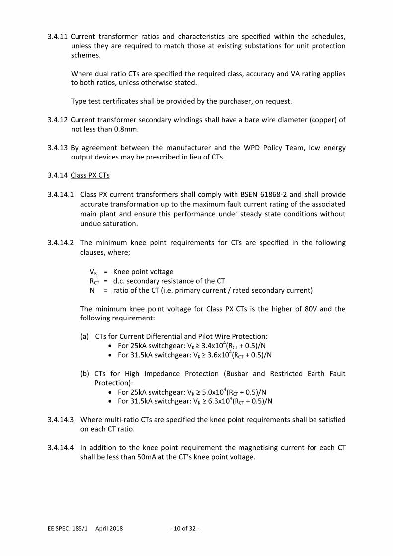
3.4.11 Current transformer ratios and characteristics are specified within the schedules, unless they are required to match those at existing substations for unit protection schemes. Where dual ratio CTs are specified the required class, accuracy and VA rating applies to both ratios, unless otherwise stated. Type test certificates shall be provided by the purchaser, on request.
3.4.12 Current transformer secondary windings shall have a bare wire diameter (copper) of not less than 0.8mm.
3.4.13 By agreement between the manufacturer and the WPD Policy Team, low energy
output devices may be prescribed in lieu of CTs. 3.4.14 Class PX CTs 3.4.14.1 Class PX current transformers shall comply with BSEN 61868-2 and shall provide
accurate transformation up to the maximum fault current rating of the associated main plant and ensure this performance under steady state conditions without undue saturation.
3.4.14.2 The minimum knee point requirements for CTs are specified in the following
clauses, where;
VK = Knee point voltage RCT = d.c. secondary resistance of the CT N = ratio of the CT (i.e. primary current / rated secondary current)
The minimum knee point voltage for Class PX CTs is the higher of 80V and the following requirement: (a) CTs for Current Differential and Pilot Wire Protection:
For 25kA switchgear: VK ≥ 3.4x10⁴(RCT + 0.5)/N For 31.5kA switchgear: VK ≥ 3.6x10⁴(RCT + 0.5)/N
(b) CTs for High Impedance Protection (Busbar and Restricted Earth Fault
Protection): For 25kA switchgear: VK ≥ 5.0x10⁴(RCT + 0.5)/N For 31.5kA switchgear: VK ≥ 6.3x10⁴(RCT + 0.5)/N
3.4.14.3 Where multi-ratio CTs are specified the knee point requirements shall be satisfied
on each CT ratio. 3.4.14.4 In addition to the knee point requirement the magnetising current for each CT
shall be less than 50mA at the CT’s knee point voltage.

EE SPEC: 185/1 April 2018 - 11 of 32 -
3.4.15 Metering Current Transformers 3.4.15.1 Metering current transformers shall have independent cores and secondary
windings from those provided for protection purposes. Provision shall be made to prevent un-authorised access to metering CTs and CT circuits.
3.4.15.2 Suitable metering CT ratios are specified in the accompanying schedules, and
chosen by WPD from the following table. 3.4.15.3 Metering CTs shall be tested to confirm compliance with BSEN 60044-1 on each
ratio. In addition to these requirements, CT errors shall be supplied for each ratio at 5%, 20%, 100% and 120% test load points at the burden specified in the following table. These additional CT errors shall either be separately tested or calculated from other error test results.
CT Ratio Options VA Rating Class Additional Error
Data 12kV Switchgear
200/100/5 300/150/5 400/200/5 600/300/5 800/400/5
1200/600/5 1600/800/5
2000/1000/5
10VA 0.2S
5%, 20%, 100% and 120% load points with a burden of 7.5VA 0.9 power factor
Table 3 Metering CT Requirements 3.4.15.4 Electronic copies of the of test certificates in PDF format, including any error tests
used as the basis of the calculations described above, shall be provided in advance of switchboard delivery for each metering current transformer. These shall be sent to the WPD project engineer by electronic mail.
3.5 Voltage Transformers 3.5.1 Voltage transformers (VTs) shall be in accordance with EA TS 41-36 with the
following additions. Dry type, encapsulated, voltage transformers are required. Facilities shall be provided for disconnecting and isolating the VT.
3.5.2 Voltage transformers used for metering and protection purposes shall comprise of
three single phase VTs connected in primary star with the centre point earthed. The secondary neutral shall also be earthed. All secondary neutral points shall be brought out to accessible terminal blocks.
3.5.3 Each VT star winding shall have a rating of 25VA per phase. Open delta windings shall
also be rated at 25VA. 3.5.4 All windings shall be rated for a voltage factor of 1.9 for 8 hours.

EE SPEC: 185/1 April 2018 - 12 of 32 -
3.5.5 All Star connected windings shall satisfy the requirements for both Class 3P and Class 0.5 irrespective of their intended use. Residual voltage windings connected to form a broken delta shall be Class 3P but are not required to satisfy Class 0.5.
3.5.6 Voltage transformer rated transformation ratios shall be in accordance with Table 4 3.5.7 Voltage transformers shall have their rated transformation ratios and voltages
shown on drawings, diagrams and rating plates as shown in Table 4.
System Voltage
Primary Winding
Secondary Windings
Protection Metering Residual[1]
Voltage (Upn) Voltage (Usn) Voltage (Usn) Voltage (Usn)
11kV 11000/√3 110/√3 110/√3 110/3
6.6kV 11000/√3
and 6600/√3
110/√3 110/√3 110/3
Table 4 VT Windings
Note 1 Where the VT is used for metering purposes an additional secondary star winding is
required.
Note 2 Voltage transformers specified for use on the 6.6kV system shall initially be selected
for use at 6.6kV. It shall be possible to subsequently convert the VT to 11kV
operation by means of internal links with minimal operational difficulty.
3.5.8 Where the three single phase voltage transformer arrangement as detailed above is
not possible or available, then a three phase 5 limb VT may be offered instead. Secondary neutral points shall be brought out and terminated in accessible terminal blocks. Three phase VTs shall have the same ratings and characteristics as detailed above.
3.5.9 Voltage Transformer Connections 3.5.9.1 VT star type secondary windings used for protection circuits shall be connected
through suitable miniature circuit breakers (MCBs) and links. The arrangement of MCBs and links shall be in accordance with Figure 1.
3.5.9.2 MCBs used for protection of the VT secondary circuits shall, unless otherwise
agreed at the time of tender, be rated at 6A and, as a minimum, satisfy the requirements of BS EN 60898. 2 adequate, normally closed auxiliary contacts shall be provided per MCB for alarm and protection blocking purposes. The status of each contact shall reflect the open/closed status of the associated MCB. MCB characteristics shall be chosen to grade with the following type and rating of fuses, over the full range of available fault current:
2A fuses to BS HD 60269-2, reference F1 and F2
2A fuses to BS HD 60269-2, reference A1

EE SPEC: 185/1 April 2018 - 13 of 32 -
3.5.9.3 Secondary windings used for metering purposed shall be fused at 6A. 3.5.9.4 VT residual windings shall be connected through removable links. 3.5.9.5 MCBs, fuses and links shall be located as close as practicable to the VT (subject to
being able to gain ready access to them with the equipment in service). 3.5.9.6 Each voltage transformer assembly shall be capable of being isolated from the
associated equipment. If isolation of the primary winding is carried out by movement of the voltage transformer assembly, a set of automatic positively-driven padlockable shutters shall be provided over the resultant apertures.
Figure 1 VT Miniature Circuit Breaker (MCB) and Link Arrangement 3.5.9.7 VT Primary windings shall be earthed independently of secondary windings.
Where three single-phase voltage transformers are used, the arrangement shall be earthed at a single point on the secondary side.
3.5.9.8 Where HV VT fuses are provided and these can be removed and replaced without
withdrawing the entire voltage transformer assembly, the means of removing the fuses shall automatically open and close automatically the access to the interior of the voltage transformer assembly and simultaneously make and break the secondary circuits.
3.5.9.9 A cover, capable of being padlocked, shall be provided so that when the entire
voltage transformer is removed from the circuit breaker equipment, access to the interior of the equipment can be prevented. It shall be possible for the circuit to be restored to service after the voltage transformer has been removed.
3.5.10 Metering Voltage Transformers 3.5.10.1 Provision shall be made for preventing access to the secondary fuses and links
associated with metering circuits and the points of access to the current and voltage wiring of the metering equipment.
3.5.10.2 Metering VTs shall be error tested by the manufacturer. In all cases individual test
certificates shall be provided. 3.5.10.3 All metering VT test certificates shall include tests to confirm compliance with
BS EN 61869-3.
Removable link
Bolted link
MCB
Key

EE SPEC: 185/1 April 2018 - 14 of 32 -
In addition, VT errors shall be supplied on brown/black (L1/L2) and black/grey (L2/L3) phases at 10VA 0.5 power factor lagging burden. These additional VT errors shall either be separately tested or alternatively calculated from other error test results.
3.5.10.4 Electronic copies of the of test certificates in PDF format, including any error tests
used as the basis of the calculations described above, shall be provided in advance of switchboard delivery for each metering voltage transformer. These shall be sent to the WPD project engineer by electronic mail.
3.5.10.5 On feeder circuits and bus section units with customer metering arrangements,
the VT connections shall, as far as possible, be before the metering current transformers in respect of normal power flow direction.
3.6 Earthing 3.6.1 Cubicle earthing requirements and earthing of small apparatus shall be in
accordance with EATS 50-18. An earth bar of not less than 25mm x 3mm copper shall be provided internally with bolted connections between cubicles. The earth bar shall be provided with means to connect the earthing of small apparatus within the cubicle.
3.7 Small wiring and Terminals 3.7.1 Small wiring and terminals shall comply with EA TS 41-36 with the following
additions:
The application of small wiring, ancillary electrical equipment and protection shall in general follow the principles in Engineering Recommendation S15.
A.C. and D.C. secondary wiring shall comprise of: o A.C. wiring: 2.5mm2 (minimum) copper stranded cable with PVC
insulation to BS6231 Type BR, or equivalent tri-rated cable complying with BS6231.
o D.C. wiring: 1.5mm2 (minimum) copper stranded cable with PVC insulation to BS6231 Type BR, or equivalent tri-rated cable complying with BS6231.
o Transducer output wiring: 1.0mm2 (minimum) stranded copper twisted pair cable with PVC insulation.
The insulation of A.C. and D.C. wiring shall be coloured white in all circuits, except earthing which shall be coloured green/yellow. A.C. and D.C. wiring shall be terminated with crimped connections in accordance with EA TS 50-18.
Terminal blocks used for protection, alarm and control circuits shall be screw clamp with spring type, in accordance with EATS 50-18 Type B. Terminal blocks for 24Vd.c. and 48Vd.c. telecontrol wiring, and for transducer output wiring shall be screw clamp type, to EATS 50-18 Type C with a hinged link for isolation purposes. Sufficient space shall be allowed so that connections can be tightened or un-tightened and wires removed and re-inserted. Spare cores shall be terminated at the terminal blocks furthest from the cable gland.
EE SPEC: 185/1 April 2018 - 15 of 32 -
All circuit breakers are to be equipped with pairs of plug test sockets of a type to be agreed at the time of tender, fitted to the trip and close circuits and connected as shown on WPD drawings. These terminals shall be mounted in accessible position within the circuit breaker control panel compartment and shall be labelled “remote trip socket” and “remote close socket”.
3.8 Fuses and Links 3.8.1 Secondary fuselinks, links and fuse carriers shall be in accordance with EATS 50-18,
BS HD 60269-2 reference A. Fuses and fuse holders up to 20A rating shall be in accordance with BS HD 60269-2 reference A1.
3.8.2 The fuse holders and bases shall be coloured as follows:
2A, 4A, 6A, 10A fuselink ratings: black colour 642 of BS 381C
16A fuselink rating: green colour 216 of BS 381C
Solid links: white 3.8.3 GE Power Controls or Mersen Red Spot fuse holders shall be provided unless
otherwise agreed at the time of tender. 3.8.4 All fuses and links shall be mounted vertically, grouped logically and consistently on
the front of the panel and shall be clearly labelled. The label shall show the function of the fuses/links and include the fuse/link number as specified on the schematic drawings. Where a double row of fuses and links is required, the labelling of the bottom row may need to be mounted on a stand-off bracket to ensure they are clearly visible. Fuses shall, as far as possible, be positioned consistently across the suite of panels and cubicles.
3.8.5 Fuse terminals shall be suitably shrouded to minimise electric shock hazards. The
incoming (supply) side of each circuit shall be connected on the bottom terminal of the fuse/link.
3.9 Protection and Alarm Relays 3.9.1 Protection, alarm and control relays shall be chosen in accordance with Schedule A
and Schedule B and with WPD’s standard drawings. Relay types shall be agreed with WPD at the time of Tender.
3.9.2 On a given suite of panels and cubicles, protection relays shall, as far as reasonably
practicable, be obtained from one relay manufacturer. The types of relays and their position shall be consistent across the suite of panels and cubicles.
3.9.3 Protection relays shall comply with ENATS 48-4, ENATS 48-5, BSEN 6025, BSEN 61810
and BSEN 61811 as appropriate and be of a type and make approved for use within Western Power Distribution. A list of approved relays and relay test blocks is included in EE SPEC:98.
3.9.4 Alternative relays can be submitted to the Technical Policy Manager for evaluation.

EE SPEC: 185/1 April 2018 - 16 of 32 -
3.9.5 Relays that can be set / programmed via a personal computer (PC) shall be provided with an accessible connection facility (e.g. a USB connection). This shall either be mounted on the front of the relay itself or on a separate connector mounted on the front of the relay panel.
3.9.6 Alarm indication functions, such as buchholz alarm, SF6 low alarm and winding
temperature alarm may be provided by programmable LEDs available on some protection relays. Alternatively, separate alarm indication relays may be provided instead.
3.9.7 Unless otherwise specified, a.c. relay inputs shall be suitable for use with 1A CT and
110V VT supplies. The d.c. auxiliary supply voltage rating shall be in accordance with the value specified on the Switchgear Enquiry/Ordering Schedule (either 110Vd.c. or 30Vd.c.). If there is any doubt over the required relay ratings the tenderer shall confirm the requirements with WPD at the time of tender.
3.10 Ancillary Equipment 3.10.1 Requirements for ancillary equipment including relays, contactors, control / selector
switches, transducers, push buttons and lamps are specified in EE SPEC: 136. 3.11 Busbar Protection 3.11.1 Busbar protection for 11kV indoor switchboards shall comprise a partial differential
protection scheme. Where space permits busbar protection relays shall be mounted on the bus-section/interconnector panel/s. If the relays cannot be accommodated on the bus-section panel/s or where there is no bus-section/interconnector panel, relays shall be mounted on a dummy switchgear panel.
3.12 Multicore / Multipair Terminal Boxes and Glands 3.12.1 Where a multicore / multipair terminal box is fitted it shall be placed so that work
can be carried out on this box with the equipment after the equipment is installed and cables jointed. With the multicores / multipairs made off, they shall not interfere with the making or breaking down of the main cable box.
3.12.2 Adequate terminal blocks shall be provided to terminate all the cores of all multicore / multipair cables. Insulated cable glands, where required shall be insulated to 4kVac. for 1 minute.
3.13 Interlocking 3.13.1 Provision for Permissive Earth and Proof of Earth interlocking shall be provided on
incoming transformer circuits (12ITA and 12ITB) as detailed in ENATS 41-36 clause 2.5.11.101.
This requirement is for use at 132/11kV and 66/11kV substations, and particularly
where double-wound secondary transformers are installed. Castell Type Q or Fortress Type H are required. Numbering/legend will be provided
at the time of order.

EE SPEC: 185/1 April 2018 - 17 of 32 -
3.14 ASC Earth Fault Detection Relay 3.14.1 The requirement for an ASC Earth Fault Detection relay will be specified at the time
of order. 3.15 Anti-Condensation Heaters 3.15.1 A heater shall be provided at an appropriate location in each panel. The heaters
shall be 230Vac. One control thermostat per switchboard shall be provided. The supply to the heater/s shall be controlled by a double pole switch which shall be located at a readily accessible position on the switchboard and clearly labelled/identified.
3.16 Ferroresonance Damping Resistors Ferroresonance damping resistors shall be provided for VT open delta windings. The
VTs and resistors shall have sufficient thermal rating to satisfy the requirements of 3.5.4.
3.17 Drawings
3.17.1 The manufacturer shall provide the following drawings for approval within one month of the commencement date of the contract or by mutually agreed date at the placement of the order. One paper copy of each drawing, prepared in accordance with EA TS 50-18 and not exceeding A1 size and one electronic copy in .pdf format shall be supplied for approval.
General Arrangement of each circuit breaker / cubicle Schematic Diagram for each circuit breaker / cubicle Wiring diagram for each circuit breaker / cubicle
3.17.2 Once approval has been obtained one further paper copy and one electronic copy in .pdf format shall be supplied. After on-site installation and commissioning of the cubicles has been completed the manufacturer shall incorporate any alterations within 3 months of the drawings being returned for correction. The manufacturer shall provide final drawings in .dwg CAD format.

EE SPEC: 185/1 April 2018 - 18 of 32 -
APPENDIX A PROTECTION FUNCTIONS
Reference Description A Alarm indication relay (used for buchholz alarm (BA), winding
temperature alarm (WTA), SF6 pressure low alarm (SF6A) etc.) AR Auto-reclose
AR(CSYNC) Auto-reclose with check synchronizing facilities AR(LLDBC) Auto-reclose with live line, dead bus charge
ASC ASC Control Relay AX Auxiliary relay
AXF Auxiliary relay with hand reset flag BBCK Busbar protection check relay
BBCKA Busbar protection check auxiliary relay 3BBOC 3 element busbar overcurrent (high impedance)
BD Biased differential BEF Balanced earth Fault CD Current Differential (unit protection) CTS CT supervision DEIT Directional IDMT earth fault
3DOCIT 3 element directional IDMT overcurrent 3DOCIT(LB) 3 element directional IDMT overcurrent with load blinding 3DOCIT(VC) 3 element voltage controlled directional IDMT overcurrent
E Instantaneous earth fault EIT IDMT earth fault
3HOC 3 element high set overcurrent IT Intertrip send/receive system
NVD Neutral voltage displacement 2OC 2 element instantaneous overcurrent 3OC 3 element instantaneous overcurrent
3OCIT 3 element IDMT overcurrent 3OV 3 element overvoltage relay PW Pilot wire protection (unit protection) RTB Relay test block SBEF Standby earth fault
SBEF1 Standby earth fault stage 1 SBEF2 Standby earth Fault stage 2
SEF Sensitive earth fault TCS Trip circuit supervision TI Trip indication relay (used in series with trip coil or trip relay coil,
e.g. buchholz trip (BT), winding temperature trip (WTT) etc.) TRS Trip relay supervision TDS Trip relay with 2.5s time delay reset contact and hand reset flag TE Trip relay with electrically reset contacts and hand reset flag TH Trip relay with hand reset contacts and flag TS Trip relay with instantaneous self reset contacts and hand reset
flag TSS Trip Supply Supervision VTS VT supervision
Z Distance protection

EE SPEC: 185/1 April 2018 - 19 of 32 -
APPENDIX B AUXILIARY SWITCHES Auxiliary switches shall comply with ENA TS 50-18. Sufficient auxiliary switches shall be provided for the associated protection and control functions. Specific requirements are defined in WPDs standard schematic drawings. In addition, each circuit breaker shall be provided with the following spare auxiliary switches, each wired back to accessible terminals blocks:
6 off normally open circuit breaker auxiliary switches 6 off normally closed circuit breaker auxiliary switches 6 off normally open busbar selector switch 6 off normally closed busbar selector switch 2 off normally open springs charged auxiliary switches 2 off normally closed springs charged auxiliary switches

EE SPEC: 185/1 April 2018 - 20 of 32 -
APPENDIX C SUPERSEDED DOCUMENTATION This document supersedes EE SPEC: 185 dated July 2017 which has now been withdrawn.
APPENDIX D ASSOCIATED DOCUMENTATION ENA TS 41-36 Switchgear for service up to 36kV (Cable and overhead line connected) ENA TS 41-24 Guidelines for design, installation, testing and maintenance of main earthing systems in substations ENA TS 50-18 Application of ancillary electrical equipment EE SPEC: 87 Protection and control cubicles for outdoor 72kV and 36kV circuit breakers and for primary substation transformers EE SPEC: 98 Approved protection, voltage control and alarm relays EE SPEC: 136 Ancillary electrical equipment for use in conjunction with switchgear and protection / control panels ST: SD4O Standard HV Connection Arrangements
APPENDIX E KEY WORDS Circuit Breaker, Panel, Cubicle, Protection, Alarm, Transducer, Telecontrol
EESPEC: 185 April 2018 - 21 of 32 -
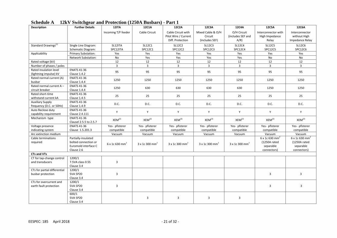
Schedule A 12kV Switchgear and Protection (1250A Busbars) - Part 1
Description
Further Details 12ITA
Incoming T/F feeder
12C1A
Cable Circuit
12C2A
Cable Circuit with Pilot Wire / Current
Diff. Protection
12C3A
Mixed Cable & O/H Circuit
(includes SEF)
12C4A
O/H Circuit (includes SEF and
A/R)
12C5A
Interconnector with High Impedance
Relay
12C6A
Interconnector without High
Impedance Relay
Standard Drawings[1] Single Line Diagram: Schematic Diagram:
SL12ITA SPC12ITA
SL12C1 SPC12C1
SL12C2 SPC12C2
SL12C3 SPC12C3
SL12C4 SPC12C4
SL12C5 SPC12C5
SL12C6 SPC12C6
Applicability Primary Substation: Yes Yes Yes Yes Yes Yes Yes
Network Substation: No Yes Yes Yes Yes No No
Rated voltage (kV) 12 12 12 12 12 12 12
Number of phases / poles 3 3 3 3 3 3 3
Rated insulation level (lightning impulse) kV
ENATS 41-36 Clause 1.4.2
95 95 95 95 95 95 95
Rated normal current (A) busbar
ENATS 41-36 Clause 1.4.4
1250 1250 1250 1250 1250 1250 1250
Rated normal current A – circuit breaker
ENATS 41-36 Clause 1.4.4
1250 630 630 630 630 1250 1250
Rated short-time withstand current kA
ENATS 41-36 Clause 1.4.5
25 25 25 25 25 25 25
Auxiliary Supply frequency (D.C. or 50Hz)
ENATS 41-36 Clause 1.4.9
D.C. D.C. D.C. D.C. D.C. D.C. D.C.
Auto Reclose duty capability requirement
ENATS 41-36 Clause 2.4.111
Y Y Y Y Y Y Y
Mechanism type ENATS 41-36 Clausel 2.5.5 to 2.5.7
XEM[2] XEM[2] XEM[2] XEM[2] XEM[2] XEM[2] XEM[2]
Voltage presence indicating system
ENATS 41-36 Clause 1.5.201.3
Yes- pfisterer compatible
Yes- pfisterer compatible
Yes- pfisterer compatible
Yes- pfisterer compatible
Yes- pfisterer compatible
Yes- pfisterer compatible
Yes- pfisterer compatible
Arc extinction medium Vacuum Vacuum Vacuum Vacuum Vacuum Vacuum Vacuum
Cable terminations required
Partially-insulated bolted connection or Euromold interface C Clause 2.6
6 x 1c 630 mm2 3 x 1c 300 mm2 3 x 1c 300 mm2 3 x 1c 300 mm2 3 x 1c 300 mm2
6 x 1c 630 mm2
(1250A rated separable
connectors)
6 x 1c 630 mm2
(1250A rated separable
connectors)
CTs and VTs
CT for tap-change control and transducers
1200/1 7.5VA class 0.5S Clause 3.4
3
CTs for partial differential busbar protection
1200/1 5VA 5P20 Clause 3.4
3 3 3
CTs for overcurrent and earth fault protection
1200/1 5VA 5P20 Clause 3.4
3 3 3
600/1 5VA 5P20 Clause 3.4
3 3 3 3

EESPEC: 185 April 2018 - 22 of 32 -
Schedule A 12kV Switchgear and Protection (1250A Busbars) - Part 1
Description
Further Details 12ITA
Incoming T/F feeder
12C1A
Cable Circuit
12C2A
Cable Circuit with Pilot Wire / Current
Diff. Protection
12C3A
Mixed Cable & O/H Circuit
(includes SEF)
12C4A
O/H Circuit (includes SEF and
A/R)
12C5A
Interconnector with High Impedance
Relay
12C6A
Interconnector without High
Impedance Relay
CT for standby earth fault protection
1200/1 15VA 5P10 Clause 3.4
1 externally mounted neutral CT
CTs for high impedance / restricted earth fault protection
1200/1 Class PX Clause 3.4
4 including 1 externally mounted
neutral CT 3 3
CTs for pilot wire protection
600/1 Class PX Clause 3.4
3
Circuit VT Clause 3.5 1 Star/star/ open delta
Busbar VT[3] Clause 3.5 (1)[1]
(Star/star/ open-delta)
(1)[1]
(Star/star/ open/delta)
(1)[1]
(Star/star/ open-delta)
(1)[1]
(Star/star/ open-delta)
Control / Relay Panel
Circuit Breaker Control Switch and Handle.
Clause 3.10 1 1 1 1 1 1 1
Local/Supervisory Switch and Handle.
Clause 3.10 1 1 1 1 1 1 1
Remote Control Terminals Clause 3.7 4 4 4 4 4 4 4
CB Open Interposing Relay
Clause 3.10 AR1 AR1 AR1 AR1 AR1 AR1 AR1
CB Close Interposing Relay
Clause 3.10 AR1 AR1 AR1 AR1 AR1 AR1 AR1
Instantaneous In/Out Relay
Clause 3.10 AR2
Instantaneous In/Out Push Buttons
Clause 3.10
PB1 PB2
SEF In/Out Relay Clause 3.10 AR2 AR2
SEF In/Out Push Buttons Clause 3.10
PB1 PB2
PB1 PB2
Auto-Reclose In/Out Relay
Clause 3.10 AR2
Auto-Reclose In/Out Push Buttons
Clause 3.10
PB1 PB2
Current / Voltage / MW and MVAR transducer
Clause 3.10 TD4 TD4 TD4 TD4 TD4 TD4
Terminal Blocks Clause 3.7 As required As required As required As required As required As required As required Fuses and Links Clause 3.8 As required As required As required As required As required As required As required

EESPEC: 185 April 2018 - 23 of 32 -
Schedule A 12kV Switchgear and Protection (1250A Busbars) - Part 1
Description
Further Details 12ITA
Incoming T/F feeder
12C1A
Cable Circuit
12C2A
Cable Circuit with Pilot Wire / Current
Diff. Protection
12C3A
Mixed Cable & O/H Circuit
(includes SEF)
12C4A
O/H Circuit (includes SEF and
A/R)
12C5A
Interconnector with High Impedance
Relay
12C6A
Interconnector without High
Impedance Relay
Test Block Clause 3.9 As specified on schematic
drawings
As specified on schematic
drawings
As specified on schematic
drawings
As specified on schematic
drawings
As specified on schematic
drawings
As specified on schematic
drawings
As specified on schematic
drawings Protection Relay 1 Clause 3.9 3DOCIT(LB)
3DOCIT(VC) TCS VTS
3OCIT EIT TCS
PW or CD 3OCIT EIT SEF TCS
3OC, 3OCIT E, EIT,
SEF AR TCS
3OCIT EIT TCS
3OCIT EIT TCS
Protection Relay 2 Clause 3.9
VTS[1] 3OCIT EIT TCS
VTS[1] VTS[1] 3BBOC
Protection Relay 3 Clause 3.9 VTS[1]
ASC Earth Fault Detection Relay
A-eberle EOR-3D (1)[3] (1)[3] (1)[3] (1)[3]
Trip relay/s Clause 3.9 TH TH TH TH TH
TH (2 off)
TH
Notes: Schedule A Part 1 Note 1: One 3 phase busbar VT and VTS relay is required per section of busbars unless all the circuits have their own feeder VTs Note 2: Alternative mechanism types will be considered at the time of tender Note 3: ASC Earth Fault Detection Relay is only required where ASC earthing is used (this typically applies to substations in Cornwall)

EESPEC: 185 April 2018 - 24 of 32 -
Schedule A 12kV Switchgear and Protection (1250A Busbars) - Part 2
Description
Further Details 12C7A
Circuit without Protection
12C8A
Outgoing Circuit with Metering
12C9A
Incoming Circuit with Metering
12C10A(M)[1]
Incoming Circuit with Directional
Protection & Partial Diff. Relay
12C11A
Incoming Circuit with Directional
Protection
12C12A(M)[1]
Incoming Circuit with Directional Protection, Pilot
Wire / Current Diff. & Partial Diff. Relay
12C13A
Incoming Circuit with Directional
Protection & Pilot Wire / Current
Diff. Protection
Standard Drawings[1] Single Line Diagram: Schematic Diagram:
SPC12C7A
SL12C8A SPC12C8A
SL12C9A SLC12C9A
SL12C10A SPC12C10A
SL12C11A SPC12C11A
SL12C12A SPC12C12A
SL12C13A SPC12C13A
Applicability Primary Substation: No Yes No No No No No
Network Substation: Yes Yes Yes Yes Yes Yes Yes
Rated voltage (kV): 12 12 12 12 12 12 12
Number of phases / poles: 3 3 3 3 3 3 3
Rated insulation level (lightning impulse) kV
ENATS 41-36 Clause 1.4.2
95 95 95 95 95 95 95
Rated normal current (A) busbar[2]
ENATS 41-36 Clause 1.4.4
1250 1250 1250 1250 1250 1250 1250
Rated normal current A – circuit breaker
ENATS 41-36 Clause 1.4.4
630 630 630 630 630 630 630
Rated short-time withstand current kA
ENATS 41-36 Clause 1.4.5
25 25 25 25 25 25 25
Auxiliary Supply frequency (D.C. or 50Hz)
ENATS 41-36 Clause 1.4.9
D.C. D.C. D.C. D.C. D.C. D.C. D.C.
Auto Reclose duty capability requirement
ENATS 41-36 Clause 2.4.111
Y Y Y Y Y Y Y
Mechanism type ENATS 41-36 Clausel 2.5.5 to 2.5.7
XEM[4] XEM[4] XEM[4] XEM[4] XEM[4] XEM[4] XEM[4]
Voltage Presence Indicating System
ENATS 41-36 Clause 1.5.201.3
Yes- pfisterer compatible
Yes- pfisterer compatible
Yes- pfisterer compatible
Yes- pfisterer compatible
Yes- pfisterer compatible
Yes- pfisterer compatible
Yes- pfisterer compatible
Arc Extinction Medium Vacuum Vacuum Vacuum Vacuum Vacuum Vacuum Vacuum
Cable Terminations Partially-insulated bolted connection or Euromold interface C Clause 2.6
3 x 1c 300 mm2 3 x 1c 300 mm2 3 x 1c 300 mm2 3 x 1c 300 mm2 3 x 1c 300 mm2 3 x 1c 300 mm2 3 x 1c 300 mm2
CTs and VTs
CTs for IDMT Protection and Analogues
600/1 5VA 5P20 Clause 3.4
3 3 2 sets of 3 2 sets of 3 2 sets of 3 2 sets of 3
CTs for Metering Details to be confirmed at time of tender. Clause 3.4
3 3 (3)[2] (3)2
CTs for transducers etc. 600/1 5VA Class 0.5S Clause 3.4
3 3
CTs for Unit Protection
600/1 Class PX Clause 3.4
3 3

EESPEC: 185 April 2018 - 25 of 32 -
Schedule A 12kV Switchgear and Protection (1250A Busbars) - Part 2
Description
Further Details 12C7A
Circuit without Protection
12C8A
Outgoing Circuit with Metering
12C9A
Incoming Circuit with Metering
12C10A(M)[1]
Incoming Circuit with Directional
Protection & Partial Diff. Relay
12C11A
Incoming Circuit with Directional
Protection
12C12A(M)[1]
Incoming Circuit with Directional Protection, Pilot
Wire / Current Diff. & Partial Diff. Relay
12C13A
Incoming Circuit with Directional
Protection & Pilot Wire / Current
Diff. Protection
Circuit VT Clause 3.5 1 Star/star/star/
open-delta
1 Star/star/star/
open-delta
1
Star/star/(star)/ open-delta[2]
1 Star/star/
open-delta
1
Star/star/(star)/ open-delta[2]
1 Star/star/
open-delta
Busbar VT Clause 3.5
Control / Relay Panel
Circuit Breaker Control Switch and Handle.
Clause 3.10 1 1 1 1 1 1 1
Local/Supervisory Switch and Handle.
Clause 3.10 1 1 1 1 1 1 1
Remote Control Terminals Clause 3.7 4 4 4 4 4 4 4
CB Open Interposing Relay. Clause 3.10 AR1 AR1 AR1 AR1 AR1 AR1 AR1
CB Close Interposing Relay Clause 3.10 AR1 AR1 AR1 AR1 AR1 AR1 AR1
Current / Voltage / MW and MVAR transducer
Clause 3.10 TD4 TD4 TD4 TD4 TD4 TD4
Terminal Blocks Clause 3.7 As required As required As required As required As required As required As required
Fuses and Links Clause 3.8 As required As required As required As required As required As required As required
Test Block Clause 3.9 As specified on schematic
drawings
As specified on schematic
drawings
As specified on schematic
drawings
As specified on schematic
drawings
As specified on schematic
drawings
As specified on schematic
drawings
As specified on schematic
drawings Protection Relay 1 Clause 3.9 3OCIT
EIT 3DOCIT
DEIT NVD TCS VTS
3OCIT EIT
3DOCIT DEIT NVD TCS VTS
3DOCIT DEIT TCS VTS
3DOCIT DEIT TCS VTS
3DOCIT DEIT TCS VTS
3DOCIT DEIT TCS VTS
Protection Relay 2 Clause 3.9
3OCIT EIT
PW or CD PW or CD
Protection Relay 3 Clause 3.9
3OCIT EIT
Trip / Supervision Relays Clause 3.9 TSS
TI (TH)[5]
TI (TI)[6]
TH TH
(TI)[7] TH
TH
Notes: Schedule A Part 2 Note 1: Where metering facilities are required the (M) suffix shall be specified otherwise the (M) shall be omitted Note 2: Metering CTs and the 2nd VT secondary star winding are only required where metering (suffix M) is specified Note 3: One 3 phase busbar VT is required per section of busbars unless all the circuits have their own feeder VTs Note 4: Alternative mechanism types will be considered at the time of tender Note 5: Hand reset trip relay is required where partial differential protection is specified Note 6: Trip indication relay is required where metering facilities (i.e. suffix M) are specified

EESPEC: 185 April 2018 - 26 of 32 -
Schedule A 12kV Switchgear and Protection (1250A Busbars) - Part 3
Description
Further Details 12B1A
Bus-section CB with 2x Partial Diff
12B2A
Bus-section CB with 1x Partial Diff Relay
12B3A
Bus-section CB without Protection
without CTs
12B4A
Bus-section CB without protection
with CTs
12B5A
Bus-section CB with 2x Partial Diff
Relays
12B6A
Bus-section Metering CB
Standard Drawings[1] Single Line Diagram: Schematic Diagram:
SL12B1 SPC12B1
SL12B2 SPC12B2
SPC12B3A
SL12B4A SPC12B4A
SL12B5A SPC12B5A
SL12B6A SPC12B6A
Applicability Primary Substation: Yes Yes No No No No
Network Substation: No No Yes Yes Yes Yes
Rated voltage (kV) 12 12 12 12 12 12
Number of phases / poles 3 3 3 3 3 3
Rated insulation level (lightning impulse withstand voltage) kV
ENATS 41-36 Clause 1.4.2 95 95 95 95 95 95
Rated normal current (A) busbar[2]
ENATS 41-36 Clause 1.4.4
1250 1250 1250 1250 1250 1250
Rated normal current A – circuit breaker
ENATS 41-36 Clause 1.4.4
1250 1250 1250 1250 1250 1250
Rated short-time withstand current kA
ENATS 41-36 Clause 1.4.5
25 25 25 25 25 25
Rated supply frequency of closing, opening and auxiliary circuits (D.C. or 50Hz)
ENATS 41-36 Clause 1.4.9
D.C. D.C. D.C. D.C. D.C. D.C.
Auto Reclose duty capability requirement
ENATS 41-36 Clause 2.4.111
Y Y Y Y Y Y
Mechanism type ENATS 41-36 Clausel 2.5.5 to 2.5.7
XEM[1] XEM[1] XEM[1] XEM[1] XEM[1] XEM[1]
Voltage Presence Indicating System
ENATS 41-36 Clause 1.5.201.3
Yes- pfisterer compatible
Yes- pfisterer compatible
Yes- pfisterer compatible
Yes- pfisterer compatible
Yes- pfisterer compatible
Yes- pfisterer compatible
Arc Extinction Medium Vacuum Vacuum Vacuum Vacuum Vacuum Vacuum
CTs and VTs
CTs for Partial Differential Busbar Protection
1200/1 or 600/1 5VA 5P20 Clause 3.4
2 sets of 3 1200/1 CTs. One set each
side of circuit breaker
2 sets of 3 1200/1 CTs. One set each side of the circuit
breaker
2 sets of 3 600/1 CTs. One set each
side of circuit breaker
2 sets of 3 600/1 CTs. One set each side of the circuit
breaker
CTs for Protection / Analogues
1200/1 5VA 5P20 Clause 3.4
3 3
600/1 5VA 5P20 Clause 3.4
3
CTs for transducers etc. 600/1 5VA Class 0.5S Clause 3.4
3

EESPEC: 185 April 2018 - 27 of 32 -
Schedule A 12kV Switchgear and Protection (1250A Busbars) - Part 3
Description
Further Details 12B1A
Bus-section CB with 2x Partial Diff
12B2A
Bus-section CB with 1x Partial Diff Relay
12B3A
Bus-section CB without Protection
without CTs
12B4A
Bus-section CB without protection
with CTs
12B5A
Bus-section CB with 2x Partial Diff
Relays
12B6A
Bus-section Metering CB
CTs for Metering Details to be confirmed at time of tender. Clause 3.4
3
Busbar VT Clause 3.5 1 Star/star/star
Control / Relay Panel
Circuit Breaker Control Switch and Handle.
Clause 3.10 1 1 1 1 1 1
Local/Supervisory Switch and Handle.
Clause 3.10 1 1 1 1 1 1
Remote Control Terminals Clause 3.7 4 4 4 4 4 4
CB Open Interposing Relay. Clause 3.10 AR1 AR1 AR1 AR1 AR1 AR1
CB Close Interposing Relay Clause 3.10 AR1 AR1 AR1 AR1 AR1 AR1
AC/DC indication interposing relay
Clause 3.10 (AR6)[2] (AR6)[2] (AR6)[2] (AR6)[2] (AR6)[2] (AR6)[2]
AC/DC/Off double pole control switch and handle
Clause 3.10 (1)[2] (1)[2] (1)[2] (1)[2] (1)[2] (1)[2]
Current / Voltage / MW and MVAR transducer
Clause 3.10 TD4 TD4 TD4
Terminal Blocks Clause 3.7 As required As required As required As required As required As required
Fuses and Links Clause 3.8 As required As required As required As required As required As required
Test Block Clause 3.9 As specified on schematic
drawings
As specified on schematic
drawings
As specified on schematic
drawings
As specified on schematic
drawings
As specified on schematic
drawings
As specified on schematic
drawings Protection Relay 1 Clause 3.9 3OCIT
EIT TCS
3OCIT EIT TCS
3OCIT EIT TCS
3OCIT EIT TCS
Protection Relay 2 Clause 3.9 3OCIT EIT
3OCIT EIT
VTS
Trip / Supervision Relays Clause 3.9 TH (2 off) TH (2 off) TSS
TH (2off) TSS
TH (2 off) TH[3]
TI Notes: Schedule A Part 3: Note 1: Alternative mechanism types will be considered at the time of tender Note 2: One AC/DC control switch, handle and interposing relay is required per switchboard Note 4: TH Trip relay is only required where partial differential busbar protection is specified

EESPEC: 185 April 2018 - 28 of 32 -
Schedule B 12kV Primary Substation Switchgear and Protection (2000A Busbars) – Part 1
Description
Further Details 12ITB
Incoming T/F feeder
12C1B
Cable Circuit
12C2B
Cable Circuit with Unit Protection
12C3B
Mixed Cable & O/H Circuit
(includes SEF)
12C4B
O/H Circuit (includes SEF and
A/R)
12C5B
Interconnector with High Impedance
Relay
12C6B
Interconnector without High
Impedance Relay
Standard Drawings[1] Single Line Diagram: Schematic Diagram:
SL12ITB SPC12ITB
SL12C1 SPC12C1
SL12C2 SPC12C2
SL12C3 SPC12C3
SL12C4 SPC12C4
SL12C5 SPSC12C5
SL12C6 SPS12C6
Applicability Primary Substation: Yes Yes Yes Yes Yes Yes Yes
Network Substation: No No No No No No No
Rated voltage (kV): 12 12 12 12 12 12 12
Number of phases / poles: 3 3 3 3 3 3 3
Rated insulation level (lightning impulse withstand voltage) kV
ENATS 41-36 Clause 1.4.2 95 95 95 95 95 95 95
Rated normal current (A) busbar
ENATS 41-36 Clause 1.4.4
2000 2000 2000 2000 2000 2000 2000
Rated normal current A – circuit breaker
ENATS 41-36 Clause 1.4.4
2000 630 630 630 630 2000 2000
Rated short-time withstand current kA
ENATS 41-36 Clause 1.4.5
25 25 25 25 25 25 25
Rated supply frequency of closing, opening and auxiliary circuits (D.C. or 50Hz)
ENATS 41-36 Clause 1.4.9
D.C. D.C. D.C. D.C. D.C. D.C. D.C.
Auto Reclose duty capability requirement
ENATS 41-36 Clause 2.4.111
Y Y Y Y Y Y Y
Mechanism type ENATS 41-36 Clause l 2.5.5 to 2.5.7
XEM[2] XEM[2] XEM[2] XEM[2] XEM[2] XEM[2] XEM[2]
Voltage presence indicating system
ENATS 41-36 Clause 1.5.201.3
Yes- pfisterer compatible
Yes- pfisterer compatible
Yes- pfisterer compatible
Yes- pfisterer compatible
Yes- pfisterer compatible
Yes- pfisterer compatible
Yes- pfisterer compatible
Arc extinction medium Vacuum Vacuum Vacuum Vacuum Vacuum Vacuum Vacuum
Cable terminations required
Partially-insulated bolted connection or Euromold interface C Clause 2.6
9 x 1c 630 mm2
(1250A rated separable
connectors)
3 x 1c 300 mm2 3 x 1c 300 mm2 3 x 1c 300 mm2 3 x 1c 300 mm2
9 x 1c 630 mm2
(1250A rated separable
connectors)
9 x 1c 630 mm2
(1250A rated separable
connectors)
CTs and VTs
CTs for partial differential busbar protection
2000/1 5VA 5P10 Clause 3.4
3 3 3
CT for tapchange control and transducers
2000/1 7.5VA class 0.5S Clause 3.4
3
CTs for over-current and earth fault protection
2000/1 5VA 5P10 Clause 3.4
3 3 3

EESPEC: 185 April 2018 - 29 of 32 -
Schedule B 12kV Primary Substation Switchgear and Protection (2000A Busbars) – Part 1
Description
Further Details 12ITB
Incoming T/F feeder
12C1B
Cable Circuit
12C2B
Cable Circuit with Unit Protection
12C3B
Mixed Cable & O/H Circuit
(includes SEF)
12C4B
O/H Circuit (includes SEF and
A/R)
12C5B
Interconnector with High Impedance
Relay
12C6B
Interconnector without High
Impedance Relay
600/1 5VA 5P20 Clause 3.4
3 3 3 3
CTs for standby earth fault protection
1200/1[4] 15VA 5P10 Clause 3.4
1 externally mounted neutral CT
CTs for high impedance / REF protection
2000/1 Class PX Clause 3.4
4 including 1 externally mounted
neutral CT 3 3
CTs for pilot wire / current differential protection
600/1 Class PX Clause 3.4
3
3Phase Feeder VT Clause 3.5 1 Star/star/
open-delta
3Phase Busbar VT Clause 3.5 (1)[1]
(Star/Star/ open-delta)
(1)[1]
(Star/Star/ open-delta)
(1)[1]
(Star/Star/ open-delta)
(1)[1]
(Star/Star/ open-delta)
Control / Relay Panel
Circuit Breaker Control Switch and Handle.
Clause 3.10 1 1 1 1 1 1 1
Local/Supervisory Switch and Handle.
Clause 3.10 1 1 1 1 1 1 1
Remote Control Terminals Clause 3.7 4 4 4 4 4 4 4
CB Open, Interposing Relay.
Clause 3.10 AR1 AR1 AR1 AR1 AR1 AR1 AR1
CB Close Interposing Relay Clause 3.10 AR1 AR1 AR1 AR1 AR1 AR1 AR1
Instantaneous In/Out Relay
Clause 3.10 AR2
Instantaneous In/Out Push Buttons
Clause 3.10
PB1 PB2
SEF In/Out Relay Clause 3.10 AR2 AR2
SEF In/Out Push Buttons Clause 3.10
PB1 PB2
PB1 PB2
Auto-Reclose In/Out Relay Clause 3.10 AR2
Auto-Reclose In/Out Push Buttons
Clause 3.10
PB1 PB2
Current, Voltage, MW and MVAR transducer
Clause 3.10 TD4 TD4 TD4 TD4 TD4 TD4
Terminal Blocks Clause 3.7 As required As required As required As required As required As required As required
Fuses and Links Clause 3.8 As required As required As required As required As required As required As required

EESPEC: 185 April 2018 - 30 of 32 -
Schedule B 12kV Primary Substation Switchgear and Protection (2000A Busbars) – Part 1
Description
Further Details 12ITB
Incoming T/F feeder
12C1B
Cable Circuit
12C2B
Cable Circuit with Unit Protection
12C3B
Mixed Cable & O/H Circuit
(includes SEF)
12C4B
O/H Circuit (includes SEF and
A/R)
12C5B
Interconnector with High Impedance
Relay
12C6B
Interconnector without High
Impedance Relay
Test Block Clause 3.9 As specified on schematic
drawings
As specified on schematic
drawings
As specified on schematic
drawings
As specified on schematic
drawings
As specified on schematic
drawings
As specified on schematic
drawings
As specified on schematic
drawings Protection Relay 1 Clause 3.9 3DOCIT(LB)
3DOCIT(VC) TCS VTS
3OCIT EIT TCS
PW or CD
3OCIT EIT SEF TCS
3OC, 3OCIT E, EIT SEF AR TCS
3OCIT EIT TCS
3OCIT EIT TCS
Protection Relay 2 Clause 3.9
VTS[1] 3OCIT EIT TCS
VTS[1] VTS[1] 3BBOC
Protection Relay 3 Clause 3.9 VTS[1]
ASC Earth Fault Detection Relay
A-eberle EOR-3D (1)[3] (1)[3] (1)[3] (1)[3]
Trip relay/s Clause 3.9 TH TH TH TH TH
TH (2 off)
TH
Notes: Schedule B Part 1: Note 1: One 3 phase busbar VT and one VTS relay is required per section of busbars unless all the circuits have their own feeder VTs Note 2: Alternative mechanism types will be considered at the time of tender Note 3: ASC earth fault detection relay is only required where ASC earthing is used (this typically applies to substations in Cornwall) Note 4: Continuous rating of 1200/1 CTs shall be at least 2000A

EESPEC: 185 April 2018 - 31 of 32 -
Schedule B 12kV Switchgear and Protection (2000A Busbars) - Part 2
Description
Further Details 12C8B
Outgoing Cable Circuit with Metering
12B1B
Bus-section CB with 2x Partial Diff
Relays for Primary Substation
12B2B
Bus-section CB with 1x Partial Diff Relay
for Primary Substation
Standard Drawings[1] Single Line Diagram: Schematic Diagram:
SL12C8B SL12C8B
SL12B1 SP12B1
SL12B2 SPC12B2
Applicability Primary Substation: Yes Yes Yes
Network Substation: No No No
Rated voltage (kV): 12 12 12
Number of phases / poles: 3 3 3
Rated insulation level (lightning impulse) kV
ENATS 41-36 Clause 1.4.2
95 95 95
Rated normal current (A) busbar[2]
ENATS 41-36 Clause 1.4.4
2000 2000 2000
Rated normal current A – circuit breaker
ENATS 41-36 Clause 1.4.4
630 2000 2000
Rated short-time withstand current kA
ENATS 41-36 Clause 1.4.5
25 25 25
Auxiliary Supply frequency (D.C. or 50Hz)
ENATS 41-36 Clause 1.4.9
D.C. D.C. D.C.
Auto Reclose duty capability requirement
ENATS 41-36 Clause 2.4.111
Y Y Y
Mechanism type ENATS 41-36 Clausel 2.5.5 to 2.5.7
XEM[1] XEM[1] XEM[1]
Voltage Presence Indicating System
ENATS 41-36 Clause 1.5.201.3
Yes- pfisterer compatible
Yes- pfisterer compatible
Yes- pfisterer compatible
Arc Extinction Medium Vacuum Vacuum Vacuum
Cable Terminations Partially-insulated bolted connection or Euromold interface C Clause 2.6
3 x 1c 300 mm2 None None
CTs and VTs
CTs for Partial Differential Busbar Protection
2000/1 5VA 5P10 Clause 3.4
2 sets of 3 2 sets of 3
CTs for OCIT and EIT Protection and Analogues
2000/1 5VA 5P10 Clause 3.4
3 3
600/1 5VA 5P20 Clause 3.4
3

EESPEC: 185 April 2018 - 32 of 32 -
Schedule B 12kV Switchgear and Protection (2000A Busbars) - Part 2
Description
Further Details 12C8B
Outgoing Cable Circuit with Metering
12B1B
Bus-section CB with 2x Partial Diff
Relays for Primary Substation
12B2B
Bus-section CB with 1x Partial Diff Relay
for Primary Substation
CTs for Metering Details to be confirmed at time of tender. Clause 3.4
3
CTs for transducer etc 600/1 5VA Class 0.5S Clause 3.4
3
Circuit VT Clause 3.5 1 Star/star/star/
open-delta
Busbar VT Clause 3.5
Control / Relay Panel
Circuit Breaker Control Switch and Handle.
Clause 3.10 1
1 1
Local/Supervisory Switch and Handle.
Clause 3.10 1 1 1
Remote Control Terminals Clause 3.7 4 4 4
CB Open Interposing Relay Clause 3.10 AR1 AR1 AR1
CB Close Interposing Relay Clause 3.10 AR1 AR1 AR1
AC/DC indication interposing relay
Clause 3.10 (AR6)[2] (AR6)[2]
AC/DC/Off double pole control switch and handle
Clause 3.10 (1)[2] (1)[2]
Current / Voltage / MW and MVAR transducer
Clause 3.10 TD4 TD4 TD4
Terminal Blocks Clause 3.7 As required As required As required
Fuses and Links Clause 3.8 As Required As required As required
Test Block Clause 3.9 As specified on schematic
drawings
As specified on schematic
drawings
As specified on schematic
drawings Protection Relay 1 Clause 3.9 3OCIT
EIT TCS
3OCIT EIT TCS
3OCIT EIT TCS
Protection Relay 2 Clause 3.9 VTS 3OCIT EIT
Trip Relays Clause 3.9 TI TH
TH (2 off)
TH (2 off)
Notes: Schedule A Part 2: Note 1: Alternative mechanism types will be considered at the time of tender Note 2: One AC/DC control switch, handle and interposing relay is required per switchboard Note 3: One 3 phase busbar VT is required per section of busbars unless all the circuits have their own feeder VTs