compact triple-band monopole antenna … triple-band monopole antenna for 2.4/5.2/5.8ghz wlan...
TRANSCRIPT

Progress In Electromagnetics Research Letters, Vol. 34, 177–186, 2012
COMPACT TRIPLE-BAND MONOPOLE ANTENNA FOR2.4/5.2/5.8GHz WLAN OPERATIONS
Y.-C. Luan*, F.-S. Zhang, and Y. Xu
National Laboratory of Antennas and Microwave Technology, XidianUniversity, Xi’an, Shaanxi 710071, P. R. China
Abstract—A novel compact monopole antenna with triple-bandoperation is proposed in this paper. The proposed antenna, fed bya 50-Ω microstrip line, consists of an inverted-L-shaped microstripfeed line loaded with a parasitic strip and a protrudent mirroredquasi-F-shaped strip on the ground plane, with a compact overallsize of 20 × 25mm2. The protrudent mirrored quasi-F-shaped stripis aimed to excite a resonant mode at 2.4 GHz. Meanwhile, withthe introduction of the parasitic strip to the inverted-L shaped strip,two adjacent resonant frequencies at 5.2/5.8 GHz are obtained. Thenumerical and experimental results exhibit the designed antennaoperates over triple frequency ranges, satisfying the standards ofwireless local area networks (WLAN) both in IEEE 802.11 b/a/g at2.4-GHz, 5.2-GHz, and 5.8-GHz. Besides, the antenna is fabricated andmeasured, and the simulation and measurement results of the returnloss, radiation patterns and peak antenna gains are studied showingthat the presented antenna is in good performance.
1. INTRODUCTION
Recently, wireless communication for wireless local area network(WLAN) has experienced tremendous growth, such as the 2.4-GHzband (2400 MHz–2484MHz) for IEEE 802.11b/g standards, the 5.2-GHz band (5150 MHz–5350MHz) and 5.8-GHz band (5725 MHz–5825MHz) for IEEE 802.11a standard. Hence, for wirelessdevice applications in the WLAN, dual- or triple-band planarantennas become the competitive candidates covering these operatingfrequencies due to the virtues of compact size, low profile, simple
Received 29 July 2012, Accepted 3 September 2012, Scheduled 12 September 2012* Corresponding author: Yu-Chen Luan (yuchen [email protected]).

178 Luan, Zhang, and Xu
fabrication and easy integration with other microwave components.To meet these requirements, various types of antenna designs havebeen studied and reported. Monopole and dipole planar antennasare investigated to fulfill dual- or triple-band operation, such as anantenna with three back-to-back pairs of dipole [1], a monopole antennawith C-shaped and S-shaped branches [2], a CPW-fed ring antennawith two L-shaped arms [3], a four-element printed dipole array withbidirectional high gain performance [4]. Dual or triple current pathsare provided by the different shaped strips of the above citations toproduce resonant frequencies at multi-bands. Some antennas withslots of different shapes and positions, including inverted E- and C-shaped slots [5], crossed double T-shaped slots [6], and inverted-Land mixing slots [7], are presented, of which the structures of sloteither cut, shift or couple with the current path to excite multi-operations. And planar inverted-F antennas (PIFA) are also showing agood performance at the desired dual or triple bands with candidates ofa PIFA consisting of three separate short-circuited patches with a triplefeed integrated [8], a PIFA with two shorted branches [9], a meanderpatch PIFA structured by two shorting pins [10]. Furthermore, somehybrid antennas composed of a simple monopole and parasitic elementsin [11, 12], with the technology of defected ground plane in [13, 14] orwith band-rejected designs of the printed wideband antenna in [15] arereported. The aforementioned designs introduce additional resonancemodes or suppress the dispensable bands for accurate expected narrowbands mitigating the interference. The above presented antennasrealize dual- or triple-band operations, but disadvantages of either largesize, complicated fabrication structure, not adequate low profile or notvery stable omni-directional radiation somewhat exist.
In this paper, a novel compact microstrip-fed monopole antennadesign with triple-band operation is proposed for 2.4/5.2/5.8 GHzWLAN applications. In the proposed design, the antenna consistsof an inverted-L strip with similar shaped parasitic element toseparate the 5 GHz band into two 5.2/5.8 GHz bands for accuratelycovering IEEE 802.11a standard of WLAN and a quasi-F-shapedprotrudent arm on the ground plane exciting the lower band for IEEE802.11 b/g of WLAN at 2.4 GHz. These design skills are adopted torealize accurate triple band operations for WLAN standard mitigatingthe unwanted interference. The proposed antenna is designed andsimulated by Ansoft HFSS simulator, and implemented with prototype.Details of the antenna design are described in the following sections,and both simulated and measured results are presented reachinga reasonable agreement with good impedance bandwidths, stableradiation characteristics and proper peak antenna gains.

Progress In Electromagnetics Research Letters, Vol. 34, 2012 179
W
L
L1
L2
ws
g
ls1
ls2
ls3
Lc
d
W2
substrate
Top view Bottom viewSide view
y
x
y
x
Wf
Lg
Figure 1. Geometry and dimensions of the proposed antenna.
2. ANTENNA DESIGN
Figure 1 illustrates the configuration of the proposed triple-bandmonopole antenna, which is designed and fabricated on Arlon AD255A(tm) substrate with relative dielectric constant (εr) of 2.55, thicknessof 1.0mm and small size of 20 × 25mm2. In the antenna design, theproposed antenna is composed of an inverted-L-shaped 50-Ω microstripfeed line with fixed width of 2.7 mm, a similar shaped parasitic stripby the side of the feed line, and a defected ground plane with aprotrudent mirrored quasi-F-shaped strip with width of 2 mm. Theprotrudent strip on the ground plane excites the lower frequency modeof 2.4-GHz for IEEE 802.11 b/g WLAN operation, with the longerhorizontal strip of length ls3 controlling this resonant band and atrigonal end at the longer horizontal strip as to improve the impedancematching condition. In order to introduce the excitation of another tworesonant modes at 5.2/5.8-GHz for IEEE 802.11a WLAN operation,the inverted-L feed line is printed on the top side of the substrate witha parasitic strip aside the feed line, which is to separate the 5-GHzband into two 5.2/5.8 GHz bands for precisely containing the IEEE802.11a standard of WLAN without frequency disturbance. Changingthe length L1 of the inverted-L feed line and the length ls1 of theparasitic element can adjust the resonant band of the IEEE 802.11astandard. The electromagnetic simulator Ansoft HFSS based on thefinite element method is applied for the required numerical analysisand to obtain the optimal geometrical parameters which are listed inTable 1.

180 Luan, Zhang, and Xu
Table 1. The optimal parameters of the proposed antenna (unit:mm).
W L Wf L1 L2 ws g ls1 ls2 W2 ls3 Lc d Lg
20 25 2.7 7 13.4 0.3 0.2 5.5 5.2 2 12.5 3.15 13 5
(a) (b)
Figure 2. Photograph of the fabricated printed triple-band monopoleantenna with optimal dimensions. (a) Top view. (b) Bottom view.
2 3 4 5 6
0
-5
-10
-15
-20
-25
Frequency (GHz)
SimulatedMeasured
S(d
B)
11
Figure 3. Simulated and measured S11 curves of the triple-bandmonopole antenna.
3. RESULTS AND DISCUSSIONS
The fabricated prototype of the proposed antenna fed by a 50-Ω SMAconnector shown in Figure 2 has been constructed and experimentally
Progress In Electromagnetics Research Letters, Vol. 34, 2012 181
(a) (b) (c)
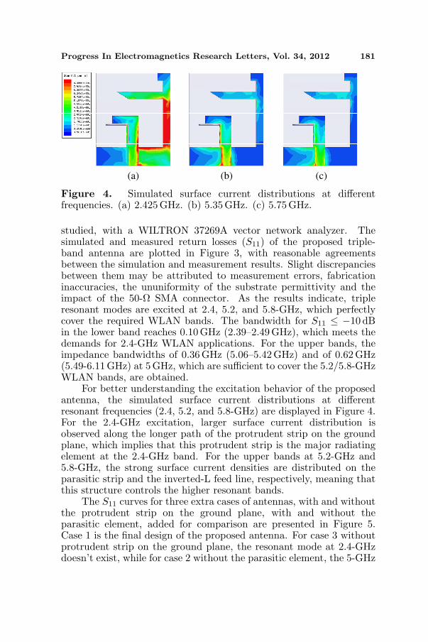
Figure 4. Simulated surface current distributions at differentfrequencies. (a) 2.425 GHz. (b) 5.35 GHz. (c) 5.75GHz.
studied, with a WILTRON 37269A vector network analyzer. Thesimulated and measured return losses (S11) of the proposed triple-band antenna are plotted in Figure 3, with reasonable agreementsbetween the simulation and measurement results. Slight discrepanciesbetween them may be attributed to measurement errors, fabricationinaccuracies, the ununiformity of the substrate permittivity and theimpact of the 50-Ω SMA connector. As the results indicate, tripleresonant modes are excited at 2.4, 5.2, and 5.8-GHz, which perfectlycover the required WLAN bands. The bandwidth for S11 ≤ −10 dBin the lower band reaches 0.10 GHz (2.39–2.49 GHz), which meets thedemands for 2.4-GHz WLAN applications. For the upper bands, theimpedance bandwidths of 0.36GHz (5.06–5.42 GHz) and of 0.62 GHz(5.49-6.11GHz) at 5GHz, which are sufficient to cover the 5.2/5.8-GHzWLAN bands, are obtained.
For better understanding the excitation behavior of the proposedantenna, the simulated surface current distributions at differentresonant frequencies (2.4, 5.2, and 5.8-GHz) are displayed in Figure 4.For the 2.4-GHz excitation, larger surface current distribution isobserved along the longer path of the protrudent strip on the groundplane, which implies that this protrudent strip is the major radiatingelement at the 2.4-GHz band. For the upper bands at 5.2-GHz and5.8-GHz, the strong surface current densities are distributed on theparasitic strip and the inverted-L feed line, respectively, meaning thatthis structure controls the higher resonant bands.
The S11 curves for three extra cases of antennas, with and withoutthe protrudent strip on the ground plane, with and without theparasitic element, added for comparison are presented in Figure 5.Case 1 is the final design of the proposed antenna. For case 3 withoutprotrudent strip on the ground plane, the resonant mode at 2.4-GHzdoesn’t exist, while for case 2 without the parasitic element, the 5-GHz

182 Luan, Zhang, and Xu
case 1 case 2 case 3 case 4
2 3 4 5 6 40
-30
-20
-10
0
case 1 case 2 case 3 case 4
S11
(dB
)
Frequency (GHz)
-
Figure 5. S11 curves of the proposed antenna in the different cases.
2 3 4 5 6-30
-20
-10
0
S11
(d
B)
Frequency (GHz)
L1 = 6.5 mm L1 = 7 mm L1 = 7.5 mm
2 3 4 5 6-30
-20
-10
0
S11
(d
B)
Frequency (GHz)
ls3 = 11.5 mm ls3 = 12.5 mm ls3 = 13.5 mm
(a) (b)
Figure 6. Simulated S11 variations for the proposed antenna ofdifferent lengths L1 and ls3. (a) L1. (b) ls3. (Other parametersare the same as in Table 1).
band isn’t separated into two bands accurately suitable for 5.2/5.8-GHzoperations. Case 4 shows that absence of the long horizontal strip onthe ground plane composing the mirrored F-shaped stub results in theimpedance mismatch.
For further investigation on resonant frequency bands, twocrucial parameters having effects on the resonant mode are analyzed.According to the simulated S11 curves for various values of L1illustrated in Figure 6(a), it is seen from the figure that increasing

Progress In Electromagnetics Research Letters, Vol. 34, 2012 183
the horizontal strip length L1 from 6.5 mm to 7.5 mm leads to theshift towards the lower frequencies of resonant modes at 5.2/5.8-GHz. Figure 6(b) shows the effect of different length ls3 on theS11 curves, indicating that the change of the length ls3 controlsthe resonant band for 2.4-GHz, simultaneously has little impact onupper ones at 5.2/5.8-GHz. Thus, from surface current distributions,and the S11 characteristic curves of different cases and various vital
0
30
60
90
120
150
180
210
240
270
300
330
-40
-30
-20
-10
0
0
30
60
90
120
150
180
210
240
270
300
330
-40
-30
-20
-10
0
EΦ (Simulated)
Eθ (Simulated)EΦ (Measured)Eθ (Measured)
(a) (b)
Figure 7. Measured and simulated normalized radiation patterns forthe proposed antenna at 2.425 GHz. (a) x-z plane. (b) y-z plane.
-40
-30
-20
-10
0
0
30
60
90
120
150
180
210
240
270
300
330
-40
-30
-20
-10
0
0
30
60
90
120
150
180
210
240
270
300
330
EΦ (Simulated)
Eθ (Simulated)EΦ (Measured)Eθ (Measured)
(a) (b)
Figure 8. Measured and simulated normalized radiation patterns forthe proposed antennas at 5.35 GHz. (a) x-z plane. (b) y-z plane.

184 Luan, Zhang, and Xu
-40
-30
-20
-10
0
0
30
60
90
120
150
180
210
240
270
300
330
-40
-30
-20
-10
0
0
30
60
90
120
150
180
210
240
270
300
330
EΦ (Simulated)
Eθ (Simulated)EΦ (Measured)Eθ (Measured)
(a) (b)
Figure 9. Measured and simulated normalized radiation patterns forthe proposed antenna at 5.75 GHz. (a) x-z plane. (b) y-z plane.
parameters of the antenna structure, we can clearly comprehend andgain a relatively deep understanding of the function of the relevantgeometrical mechanism on the impedance matching condition of theproposed antenna.
The far-field measured and simulated normalized radiationpatterns of the proposed triple-band monopole antenna are alsoinvestigated. Figures 7–9 show the measured and simulatedradiation patterns including the vertical (Eθ) and the horizontal (EΦ)polarization patterns of the proposed antenna at 2.425, 5.35 and5.75GHz, respectively. It can be obviously noticed that the nearlyomni-directional radiation in the H plane (x-z plane) and bidirectionalradiation in the E plane (y-z plane) for all the triple operation bandsare obtained, which show a monopole-like radiation characteristics.The measured results of the radiation patterns are in accordance withthe simulated ones with acceptable discrepancies which may result fromthe influence of the anechoic chamber environment. That is, stableradiation patterns have been obtained for the proposed antenna.
The measured and simulated peak gains of the proposed antennafor frequencies across the triple operating bands are stable andacceptable, as illustrated in Figure 10. The measured peak antennagains are about 1.8–2.7 dBi for the 2.4-GHz band, 2.5–3.1 dBi for the5.2-GHz band and 2.6–2.8 dBi for the 5.8 GHz band. For the 2.4-GHz band, the gain variations are less than 0.9 dBi, while for the5.2-GHz and 5.8-GHz bands, the gain variations are less than 0.6 dBi,respectively.

Progress In Electromagnetics Research Letters, Vol. 34, 2012 185
2 3 4 5 6
4
3
2
1
SimulatedMeasured
Frequency (GHz)
Pea
k G
ain (
dB
i)
Figure 10. Measured and simulated peak antenna gains of theproposed antenna for the triple bands.
4. CONCLUSION
A novel compact monopole antenna with triple-band operation isdesigned, investigated and fabricated in this paper. By introducing aparasitic element to the monopole feed line and a protrudent mirroredquasi-F-shaped strip on the ground plane, the prototype of theantenna with an area of 20× 25mm2 has achieved satisfactory multi-band performance for WLAN application, which obtains impedancebandwidths of 2.39–2.49GHz, 5.06–5.42 GHz and 5.49–6.11 GHz,respectively. The radiating mechanism and the effects of differentdimensions on the feature of the proposed antenna have also beendiscussed. Due to the good radiation pattern performance, stable gainsacross the triple bands and the above features, the proposed antennahas wide and promising applications for wireless communicationsystems.
REFERENCES
1. Wu, Y.-J., B.-H. Sun, J.-F. Li, and Q.-Z. Liu, “Triple-bandomni-directional antenna for WLAN application,” Progress InElectromagnetics Research, Vol. 76, 477–484, 2007.
2. Li, F., L.-S. Ren, G. Zhao, and Y.-C. Jiao, “Compact triple-bandmonopole antenna with C-shaped and S-shaped meander stripsfor WLAN/WiMAX applications,” Progress In ElectromagneticsResearch Letters, Vol. 15, 107–116, 2010.
3. Rezaeieh, S. A., “Compact dual band CPW-fed monopoleantenna with L-strips for WLAN/WiMAX applications,” 19thTelecommunications Forum (TELFOR), 1602–1604, 2011.

186 Luan, Zhang, and Xu
4. Li, X., L. Yang, S.-X. Gong, and Y.-J. Yang, “Bidirectionalhigh gain antenna for WLAN applications,” Progress InElectromagnetics Research Letters, Vol. 6, 99–106, 2009.
5. Zhang, S.-M., F.-S. Zhang, W.-M. Li, W.-Z. Li and H.-Y. Wu, “Amulti-band monopole antenna with two different slots for WLANand WiMAX applications,” Progress In Electromagnetics ResearchLetters, Vol. 28, 173–181, 2012.
6. Ren, F.-C., F.-S. Zhang, J.-H. Bao, B. Chen, and Y.-C. Jiao,“Compact triple-frequency slot antenna for WLAN/WiMAXoperations,” Progress In Electromagnetics Research Letters,Vol. 26, 21–30, 2011.
7. Lee, Y.-C. and J.-S. Sun, “Compact printed slot antennasfor wireless dual-and multi-band operations,” Progress InElectromagnetics Research, Vol. 88, 289–305, 2008.
8. Song, C. T. P., P. S. Hall, H. Ghafouri-Shiraz, and D. Wake,“Triple band planar inverted F antennas for handheld devices,”Electron. Lett., Vol. 36, No. 2, 112–114, 2000.
9. Hsiao, F.-R. and K.-L. Wong, “Compact planar inverted-F patchantenna for triple-frequency operation,” Microwave Opt. Technol.Lett., Vol. 33, No. 6, 459–462, 2002.
10. Dou, W. P. and Y. W. M. Chia, “Novel meandered planarinverted-F antenna for triple-frequency operation,” MicrowaveOpt. Technol. Lett., Vol. 27, No. 1, 58–60, Oct. 5, 2000; Dig.,112–115.
11. Abaga Abessolo, M. A., A. El Moussaoui, and N. Aknin,“Dual-band monopole antenna with omega particles for wirelessapplications,” Progress In Electromagnetics Research Letters,Vol. 24, 27–34, 2011.
12. Jan, J.-Y. and L.-C. Tseng, “Small planar monopole antenna witha shorted parasitic inverted-L wire for wireless communicationsin the 2.4-, 5.2-, and 5.8-GHz bands,” IEEE Trans. AntennasPropag., Vol. 52, No. 7, 1903–1905, 2004.
13. Antoniades, M. A. and G. V. Eleftheriades, “A compactmultiband monopole antenna with a defected ground plane,”IEEE Antennas Wireless Propagat. Lett., Vol. 7, 652–655, 2008.
14. Li, R.-H., X.-W. Shi, N. Zhang, Y.-F. Wang, and Y.-J. Wang,“A novel compact dual-band antenna for WLAN applications,”Microwave Opt. Technol. Lett., Vol. 54, No. 6, 1476–1479, 2012.
15. Chen, W.-S. and K.-Y. Ku, “Band-rejected design of the printedopen slot antenna for WLAN/WiMAX operation,” IEEE Trans.Antennas Propag., Vol. 56, No. 4, 1163–1169, 2008.