compact soft x-ray microscopy - diva portal9332/fulltext01.pdf · compact soft x-ray microscopy...
TRANSCRIPT

Compact Soft X-Ray Microscopy
Goran Johansson
Stockholm 2003
Doctoral Thesis
Royal Institute of Technology
Department of Physics

Akademisk avhandling som med tillstand av Kungl Tekniska Hogskolan framlagges till of-fentlig granskning for avlaggande av teknisk doktorsexamen fredagen den 23 maj 2003kl 14.00 i Kollegiesalen, Administrationsbyggnaden, Kungl Tekniska Hogskolan, Valhalla-vagen 79, Stockholm.
ISBN 91-7283-502-8
TRITA-FYS-2003:15ISSN 0280-316XISRN KTH/FYS/--03:15--SE
c© Goran Johansson, Maj 2003
Universitetsservice US ABStockholm 2003www.us-ab.com

Abstract
This thesis describes the development of soft x-ray reflective optics, instrumentation andapplications for compact soft x-ray microscopy. The microscope is based on a table-topliquid-jet-target laser-plasma source in combination with a spherical normal-incidence mul-tilayer condenser mirror and nanofabricated diffractive optics for imaging. High-resolutionimaging is performed at the wavelength 3.374 nm in the water-window (2.3 – 4.4 nm), wherenatural contrast between carbon and oxygen allows imaging of unstained biological materialin their natural aqueous environment.
The design and implementation of a compact soft x-ray reflectometer based on a laser-plasma source is described. The reflectometer allows rapid and accurate characterization ofnormal-incidence multilayer coatings used at water-window wavelengths. This instrument,which measures absolute reflectivity and multilayer period, is now used in the fabricationprocess, aiming to improve the soft x-ray normal-incidence multilayer condenser systemof the compact soft x-ray microscope. Latest results from the development process arepresented.
A new design of the compact soft x-ray microscope, with improvements in mechanicaland thermal stability, provides user-friendly and daily operation. This includes also anew nozzle design for the liquid-jet-target laser-plasma source, which enables higher sourcestability and operation with cryogenic liquids. In addition, a new experimental arrangementunder construction is briefly described. It will utilize a condenser zone plate and operateat the wavelength 2.478 nm.
Finally, performance test of the compact soft x-ray microscope is presented and dis-cussed. In addition, a project to explore the use of soft x-ray microscopy for imagingsensory cells is described. The high-resolution imaging of these cells was performed atthe synchrotron-based soft x-ray microscope at Lawrence Berkeley National Laboratory(LBNL).
ISBN 91-7283-502-8 • TRITA-FYS-2003:15 • ISSN 0280-316X • ISRN KTH/FYS/--03:15--SE
iii


List of papers
Paper 1 G. A. Johansson, M. Berglund, F. Eriksson, J. Birch, and H. M. Hertz, “Compact softx-ray reflectometer based on a line-emitting laser-plasma source”, Rev. Sci. Instrum.72, 58 (2001).
Paper 2 G. A. Johansson, M. Berglund, F. Eriksson, J. Birch, and H. M. Hertz, “Accuratemultilayer period determination with laser-plasma water-window reflectometer”, SPIE4144, 82 (2000).
Paper 3 F. Eriksson, G. A. Johansson, H. M. Hertz, and J. Birch, “Enhanced Soft X-rayReflectivity of Cr/Sc Multilayers by Ion Assisted Sputter Deposition”, Opt. Eng.41(11) 2903-2909 (2002).
Paper 4 G. A. Johansson, A. Holmberg, H. M. Hertz, and M. Berglund, “Design and perfor-mance of a laser-plasma based compact soft x-ray microscope”, Rev. Sci. Instrum.73,1193 (2002).
Paper 5 F. Eriksson, G. A. Johansson, H. M. Hertz, E. M. Gullikson, U. Kreissig, and J. Birch,“14.5% normal-incidence reflectance of Cr/Sc x-ray multilayer mirrors for the waterwindow”, submitted to Opt. Lett.
Paper 6 G. A. Johansson, S. M. Khanna, G. Denbeaux, and M. Ulfendahl, “Exploring the useof Soft X-Ray Microscopy for Imaging Sensory Cells”, submitted to Histochem. CellBiol.
Paper 7 J. de Groot, G. A. Johansson, and H. M. Hertz, “Capillary nozzles for liquid-jetlaser-plasma x-ray sources”, submitted to Rev. Sci. Instrum.
v


Contents
List of papers v
1 Introduction 1
1.1 Background . . . . . . . . . . . . . . . . . . . . . . . . . . . . . . . . . . . . 11.2 Microscopy . . . . . . . . . . . . . . . . . . . . . . . . . . . . . . . . . . . . 11.3 Soft x-ray radiation and technology . . . . . . . . . . . . . . . . . . . . . . . 2
1.3.1 The x-ray spectrum . . . . . . . . . . . . . . . . . . . . . . . . . . . 21.3.2 X-ray applications . . . . . . . . . . . . . . . . . . . . . . . . . . . . 3
1.4 Overview of the dissertation . . . . . . . . . . . . . . . . . . . . . . . . . . . 3
2 Soft x-ray sources 5
2.1 Electron-impact sources . . . . . . . . . . . . . . . . . . . . . . . . . . . . . 52.2 Synchrotron radiation . . . . . . . . . . . . . . . . . . . . . . . . . . . . . . 62.3 Free-electron lasers . . . . . . . . . . . . . . . . . . . . . . . . . . . . . . . . 72.4 Laser-produced plasmas . . . . . . . . . . . . . . . . . . . . . . . . . . . . . 82.5 Discharge sources . . . . . . . . . . . . . . . . . . . . . . . . . . . . . . . . . 102.6 X-ray lasers and high harmonic generation . . . . . . . . . . . . . . . . . . . 10
3 X-ray optics 13
3.1 Introduction . . . . . . . . . . . . . . . . . . . . . . . . . . . . . . . . . . . . 133.2 Diffractive x-ray optics . . . . . . . . . . . . . . . . . . . . . . . . . . . . . . 13
3.2.1 Diffraction gratings . . . . . . . . . . . . . . . . . . . . . . . . . . . . 143.2.2 Fresnel zone plates . . . . . . . . . . . . . . . . . . . . . . . . . . . . 14
3.3 Refractive x-ray optics . . . . . . . . . . . . . . . . . . . . . . . . . . . . . . 153.4 Reflective x-ray optics . . . . . . . . . . . . . . . . . . . . . . . . . . . . . . 16
3.4.1 Reflective properties of solid materials . . . . . . . . . . . . . . . . . 163.4.2 Grazing-incidence optics . . . . . . . . . . . . . . . . . . . . . . . . . 17
3.5 Multilayer optics . . . . . . . . . . . . . . . . . . . . . . . . . . . . . . . . . 183.5.1 Multilayer theory . . . . . . . . . . . . . . . . . . . . . . . . . . . . . 193.5.2 Optimizing multilayer coatings . . . . . . . . . . . . . . . . . . . . . 203.5.3 Multilayer fabrication . . . . . . . . . . . . . . . . . . . . . . . . . . 21
4 Multilayer mirror characterization 23
4.1 Hard x-ray diffraction . . . . . . . . . . . . . . . . . . . . . . . . . . . . . . 234.2 Soft x-ray synchrotron-based reflectometers . . . . . . . . . . . . . . . . . . 24
4.2.1 ALS reflectometer . . . . . . . . . . . . . . . . . . . . . . . . . . . . 244.2.2 BESSY reflectometer . . . . . . . . . . . . . . . . . . . . . . . . . . . 25
4.3 Compact soft x-ray reflectometer . . . . . . . . . . . . . . . . . . . . . . . . 25
vii
viii Contents
4.3.1 Experimental arrangement . . . . . . . . . . . . . . . . . . . . . . . 254.3.2 Multilayer period measurements . . . . . . . . . . . . . . . . . . . . 264.3.3 Absolute reflectivity measurements . . . . . . . . . . . . . . . . . . . 27
4.4 Conclusions . . . . . . . . . . . . . . . . . . . . . . . . . . . . . . . . . . . . 28
5 Characteristics of soft x-ray microscopy 29
5.1 Introduction . . . . . . . . . . . . . . . . . . . . . . . . . . . . . . . . . . . . 295.2 Resolution and contrast . . . . . . . . . . . . . . . . . . . . . . . . . . . . . 295.3 Sample preparation and fixation . . . . . . . . . . . . . . . . . . . . . . . . 305.4 Radiation damage . . . . . . . . . . . . . . . . . . . . . . . . . . . . . . . . 315.5 Synchrotron-based soft x-ray microscopes . . . . . . . . . . . . . . . . . . . 31
5.5.1 Transmission x-ray microscopy . . . . . . . . . . . . . . . . . . . . . 315.5.2 Scanning soft x-ray microscopy . . . . . . . . . . . . . . . . . . . . . 32
5.6 Final remarks . . . . . . . . . . . . . . . . . . . . . . . . . . . . . . . . . . . 32
6 Compact soft x-ray microscopy 33
6.1 Introduction . . . . . . . . . . . . . . . . . . . . . . . . . . . . . . . . . . . . 336.2 Soft x-ray liquid-jet laser-plasma source . . . . . . . . . . . . . . . . . . . . 34
6.2.1 Principles of operation . . . . . . . . . . . . . . . . . . . . . . . . . . 346.2.2 Characteristics of the x-ray emission . . . . . . . . . . . . . . . . . . 35
6.3 Condenser arrangement . . . . . . . . . . . . . . . . . . . . . . . . . . . . . 366.3.1 Normal-incidence spherical multilayer condenser . . . . . . . . . . . 366.3.2 Condenser zone plate . . . . . . . . . . . . . . . . . . . . . . . . . . 38
6.4 Sample holder arrangement . . . . . . . . . . . . . . . . . . . . . . . . . . . 386.5 Imaging diffractive x-ray optics . . . . . . . . . . . . . . . . . . . . . . . . . 396.6 Image detector . . . . . . . . . . . . . . . . . . . . . . . . . . . . . . . . . . 406.7 Future development . . . . . . . . . . . . . . . . . . . . . . . . . . . . . . . 40
6.7.1 Instrumentation . . . . . . . . . . . . . . . . . . . . . . . . . . . . . 406.7.2 Exposure time . . . . . . . . . . . . . . . . . . . . . . . . . . . . . . 406.7.3 Shorter wavelength . . . . . . . . . . . . . . . . . . . . . . . . . . . . 40
7 Applications of soft x-ray microscopy 41
7.1 Introduction . . . . . . . . . . . . . . . . . . . . . . . . . . . . . . . . . . . . 417.2 Performance tests of the compact soft x-ray microscope . . . . . . . . . . . 41
7.2.1 Test samples . . . . . . . . . . . . . . . . . . . . . . . . . . . . . . . 417.2.2 Toward biological applications . . . . . . . . . . . . . . . . . . . . . 42
7.3 Biological studies at XM-1 . . . . . . . . . . . . . . . . . . . . . . . . . . . . 43
8 Summary of the papers 47
9 Other publications 49
Acknowledgments 51
Bibliography 53
Chapter 1
Introduction
1.1 Background
The work presented in this dissertation is part of a soft x-ray microscopy project at theRoyal Institute of Technology (KTH), Sweden. The purpose is to develop a table-top softx-ray microscope with substantially higher resolution than optical microscopy, while stilltrying to keep the unparalleled powers and user friendliness of the latter. This is achievedby combining a laser-plasma soft x-ray source with state-of-the-art diffractive and reflectivesoft x-ray optics.
Soft x-ray microscopy is today a well established, although still young, method foranalyzing microscopic structures. The applications cover a wide range from biological tomaterials science. Several sub-methods besides absorption imaging has evolved, such asspectromicroscopy and specific labeling for functional studies.
One of the more severely limiting factors for the spread of the soft x-ray microscopytechnology is the access to suitable light sources. Virtually all existing soft x-ray microscopesin operation today are therefore located at high-brightness synchrotron radiation facilities.Moreover, appropriate synchrotrons only exist on a few places in the world which limitsthe number of available soft x-ray microscopes to a handful. Consequently, the numbers ofpresent and potential users are quite few. One way to increase the access to this promisingtechnology would be to develop a table-top soft x-ray microscope which could be locatedin a large number of small-scale laboratories. This is one of the main goals of the compactsoft x-ray microscopy project presented in this thesis.
1.2 Microscopy
The first optical compound microscopes started to emerge in the late sixteenth century. Butit was not until the theoretical foundation of light microscopy was established by Ernst Abbe[1, 2] in the end of the 19th century, that optics could be refined and the diffraction limitcould be reached. The optical microscope has since then been one of the most importanttools in the scientific laboratory, but the desire to study even smaller structures than thevisible light permit has led to the development of various high-resolution techniques.
Electron microscopy was invented in the 1930s by Knoll and Ruska, and was rapidlydeveloped into an important instrument for biology and material science research. Theuse of electrons with much shorter de Broglie wavelength than light enables a resolutioncomparable to the size of single atoms. Transmission and scanning electron microscopy are
1

2 Chapter 1. Introduction
the two main approaches for imaging, but the possibility to perform different types of x-rayand electron spectroscopy have become increasingly important.
A third very successful method for studying surface structures with atomic resolutionconsists of a group of scanning-probe techniques such as atomic force microscopy (AFM) [3]and scanning tunneling microscopy (STM) [4]. Although limited to the surface of a samplethese instruments have become very popular and can, besides the main field of materialscience, even be used for examination of wet biological samples.
Although suggestions on utilizing x-rays for microscopy came shortly after the discoveryof x-rays, the lack of suitable sources and optics inhibited development until the 1970s [5].Soft x-ray microscopy with high resolution is therefore a relatively new method and couldbe realized only after the implementation of x-ray diffractive optics. It uses a small portionof the x-ray spectrum where the wavelength is around a few nanometers and the interactionbetween atoms and the radiation is particularly strong. Microscopy using hard x-rays isstill struggling with inefficient optics, but is making good progress.
1.3 Soft x-ray radiation and technology
Since the discovery of x-rays more than a hundred years ago by the German physicist W. C.Rontgen [6], this type of electromagnetic radiation has been used extensively to investigatethe structure of matter. This section gives a very brief overview of the properties of softx-rays, and also the experimental methods and tools that are used in this research field.This is extensively covered in several text books, e.g., Ref. [7–10].
1.3.1 The x-ray spectrum
1 nm 0.1 nm10 nmWavelength
Cu-Kα
Photon energy 100 eV 1 keV 10 keV
C-K O-K
Water window
Extreme Ultraviolet
Soft X-Rays
Hard X-Rays
Figure 1.1. The portion of the electromagnetic spectrum that is referred to as the EUV andx-ray spectrum.
Figure 1.1 shows a region of the electromagnetic spectrum that is referred to as theextreme ultraviolet (EUV) and x-ray spectrum. Also marked in the figure are the K-absorption edges of carbon and oxygen which spans a narrow wavelength range that definesthe so-called water window. Furthermore, the emission line of Cu Kα is marked, which isfrequently used for x-ray diffraction.
1.4. Overview of the dissertation 3
1.3.2 X-ray applications
X-rays have been used extensively since their discovery in 1895. The first and still dominat-ing application is medical examinations [11]. Thereafter comes different x-ray techniquesused in material science to investigate the internal structures of matter. One such technique,x-ray diffraction (XRD) has spread into biology and, e.g., protein crystallography is nowan important research field. X-ray spectroscopy is vital for investigating the interactionbetween matter and photons. For example, in x-ray fluorescence (XRF), x-ray photoelec-tron spectroscopy (XPS), and Auger electron spectroscopy (AES) the emitted electronsand photons are analyzed, while the absorption processes can be studied in x-ray absorp-tion spectroscopy (XAS). EUV and soft x-ray astronomy have benefited from the advancesin x-ray optics and are, e.g., using rocket-launched telescopes to image the solar activity.Also, at EUV wavelengths, a massive research effort is made to develop a new lithographysystem with high resolution for the semiconductor industry. Finally, there is soft x-raymicroscopy which is within the scope of this thesis.
1.4 Overview of the dissertation
This thesis focuses on the development of optics, instrumentation, and applications forcompact soft x-ray microscopy. The first chapter contains a short and brief introduction tox-ray science and microscopy. Chapter two describes the different ways of generating softx-rays. The third chapter deals with x-ray optics and puts emphasis on multilayer reflectivecoatings, and then chapter 4 follows with the characterization of multilayer mirrors. Chapter5 describes the characteristics of soft x-ray microscopy from the viewpoint of its usage. Next,chapter 6 summarize compact soft x-ray microscopy and describes various experimentalarrangements in more detail. Finally, some performance tests and applications of soft x-raymicroscopy are presented in chapter 7.

Chapter 2
Soft x-ray sources
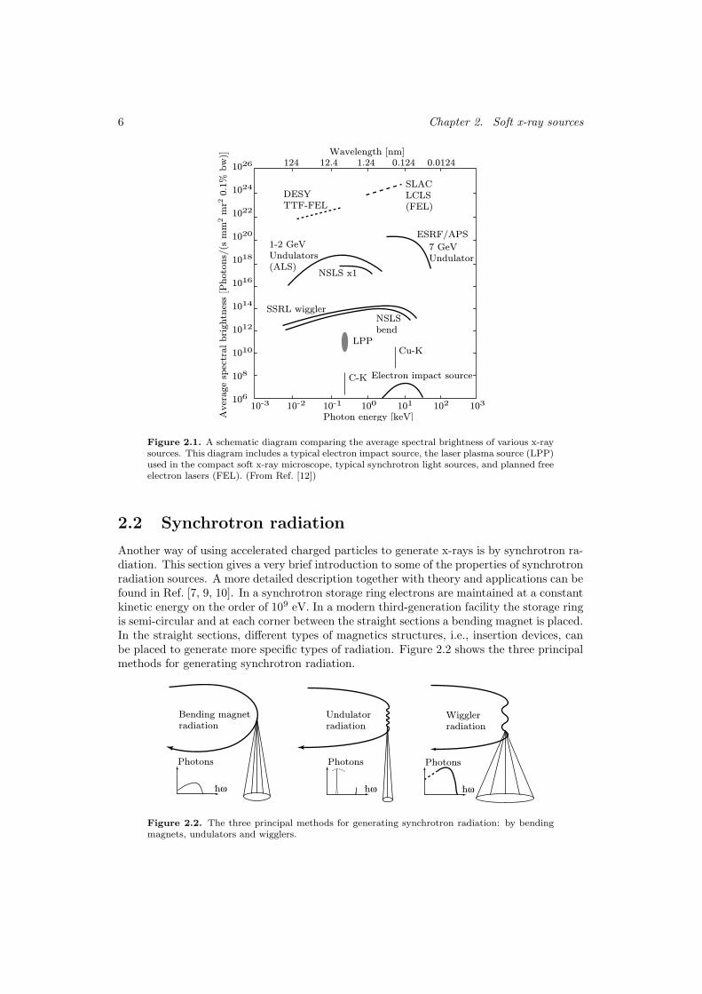
Since there are very few natural sources generating x-rays this has to be done artificially.The first type of laboratory source ever to generate x-rays was the electron-impact sourceinvented by Rontgen. This source generated rather hard x-rays and gained enormous impactin, e.g., medical diagnostics and x-ray diffraction of crystals. However, the utilization of thesoft x-ray and EUV spectral range occurred much later due to technical difficulties. It wasnot only the lack of suitable sources and optics but also the requirement of operating theexperiments in vacuum and insensitive detectors that impeded the development within thisspectral region. Today, there exist a multitude of soft x-ray sources, and the developmentof those and new ones are quite intense. Figure 2.1 shows a comparison of average spectralbrightness for various existing and planned x-ray sources. Besides synchrotron radiationsources and conventional electron impact sources, the laser plasma source (LPP) used inour compact soft x-ray microscope and planned free-electron lasers (FEL) are shown in thefigure. Generally, soft x-ray microscopy requires a monochromatic high-spectral-brightnesssource and preferably it should also be coherent and tunable in wavelength. Until today,the obvious choice has been a synchrotron radiation source, but the laser-produced plasmasources are an alternative, although it is neither coherent nor tunable. Furthermore, thedevelopment of table-top x-ray lasers and high-harmonic sources with interesting coherenceproperties show great progress. This chapter summarizes the sources and puts specialemphasis on laser-produced plasma sources since they are of decisive importance for thedevelopment of a table-top soft x-ray microscope.
2.1 Electron-impact sources
In the electron-impact source [6, 8, 13], electrons emitted from a cathode are accelerated bya high electric voltage. When the electrons impact into the target anode some of them willbe decelerated due to Coulomb interaction between the electron and a nucleus of the targetmaterial. As always when a charge is accelerated or decelerated it will emit electromagneticradiation. The result is a continuous x-ray spectrum, with photon energies ranging fromzero to the maximum that the acceleration potential can provide. Furthermore, an electronimpacting onto a target atom can also remove one of the inner-core electrons. When theatom relaxes it will emit an x-ray photon with very well-defined energy and the resultingspectrum consists of lines, with energies characteristic to the target material. Unfortunately,the electron impact source has still a very low spectral brightness in the soft x-ray region.
5
6 Chapter 2. Soft x-ray sources
1-2 GeVUndulators(ALS)
NSLS x1
Photon energy [keV]
Electron impact source
ESRF/APS
SLACLCLS(FEL)
Cu-K
C-K
LPP
DESYTTF-FEL
SSRL wigglerNSLSbend
Aver
age
spec
tral bri
ghtn
ess
[Photo
ns/
(s m
m2 m
r2 0
.1%
bw
)]
7 GeVUndulator
124 12.4 1.24 0.124 0.0124Wavelength [nm]
10-3 10010-2 10-1 101 102 103
1022
1018
1016
1014
1020
1012
1010
106
1026
1024
108
Figure 2.1. A schematic diagram comparing the average spectral brightness of various x-raysources. This diagram includes a typical electron impact source, the laser plasma source (LPP)used in the compact soft x-ray microscope, typical synchrotron light sources, and planned freeelectron lasers (FEL). (From Ref. [12])
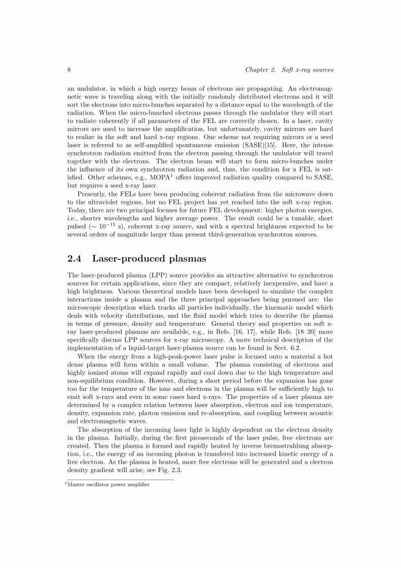
2.2 Synchrotron radiation
Another way of using accelerated charged particles to generate x-rays is by synchrotron ra-diation. This section gives a very brief introduction to some of the properties of synchrotronradiation sources. A more detailed description together with theory and applications can befound in Ref. [7, 9, 10]. In a synchrotron storage ring electrons are maintained at a constantkinetic energy on the order of 109 eV. In a modern third-generation facility the storage ringis semi-circular and at each corner between the straight sections a bending magnet is placed.In the straight sections, different types of magnetics structures, i.e., insertion devices, canbe placed to generate more specific types of radiation. Figure 2.2 shows the three principalmethods for generating synchrotron radiation.
Bending magnet
radiation
Photons
hω
Wiggler
radiation
Photons
hω
Undulator
radiation
Photons
hω
Figure 2.2. The three principal methods for generating synchrotron radiation: by bendingmagnets, undulators and wigglers.

2.3. Free-electron lasers 7
When the electron beam is bent, i.e., accelerated by these magnets, photons are emittedwith a broadband energy spectrum. The wavelength spectrum usually covers from infraredto soft x-rays. The dipole radiation from the electrons will, due to relativistic effects, betransformed into a narrow cone in the forward direction in the laboratory frame of reference.One fundamental parameter to characterize bending magnet radiation is the critical photonenergy, which is defined as the photon energy for which half the power is emitted above andhalf below, and is given by
~ωc =3e~Bγ2
2m, (2.1)
where B is the magnetic field, γ is the ratio of the electron mass m to its rest mass m0
given by γ = E/m0c2 and E is the kinetic energy of the electrons.
Insertion devices, e.g., wigglers and undulators, consisting of periodic magnetic struc-tures are placed in the straight sections between the bending magnets. These devices canproduce a more narrow photon energy spectrum and the radiation cone can also be mademore narrow. Due to the magnet structure the electrons will perform a periodic deviationfrom the straight path and, thus, radiate photons. The shape of these oscillations dependscritically on the magnetic field strength and a primary non-dimensional parameter char-acterizing the strength of these deviations is usually referred to as the magnetic deflection
parameter :
K =eB0λu2πmc
, (2.2)
where B0 is the amplitude of the periodic magnetic field and λu is the period of the magneticstructure.
For a K < 1, the insertion device is referred to as an undulator and is characterized as apartially coherent, tunable, narrow bandwidth, and high spectral brightness source. Due tothe relatively weak magnetic field the electrons will perform a near sinusoidal motion andwithin the central radiation cone defined by θcen = 1/γ
√N the bandwidth will be
∆λ
λ=
1
N, (2.3)
where N is the number of periods in the undulator.When K À 1, the device is called a wiggler and the high magnetic field will make the
deviation of the electron beam larger and non-sinusoidal. Therefore, a large number ofhigher harmonics will emerge and especially for higher photon energies these will mergeinto a continuum. Compared with bending magnets and undulators, the wiggler provideshigher photon energies and high photon flux.
Generally, the characteristics of synchrotron radiation is very high spectral brightnessdue to the narrow electron beam and, due to relativistic effects, the narrow radiation conedirected outward tangentially. Furthermore, with undulators and wigglers in combinationwith monochromators the energy of the photons can be selected with a very narrow band-width. The polarization from the different devices is well known and is frequently utilizedin experiments. The photon flux from a synchrotron storage ring is not continuous, butpulsed with a pulse length of typically 10−11 − 10−10 s and a pulse separation of the orderof ns. A synchrotron radiation source offers an excellent radiation quality and stability, butthe size of the facility and the price tag can be deterrently large.
2.3 Free-electron lasers
Free-electron lasers (FEL) are considered to be the next generation in the evolution of syn-chrotron radiation sources [12, 14]. The FEL consists of a periodic magnetic structure, i.e.,
8 Chapter 2. Soft x-ray sources
an undulator, in which a high energy beam of electrons are propagating. An electromag-netic wave is traveling along with the initially randomly distributed electrons and it willsort the electrons into micro-bunches separated by a distance equal to the wavelength of theradiation. When the micro-bunched electrons passes through the undulator they will startto radiate coherently if all parameters of the FEL are correctly chosen. In a laser, cavitymirrors are used to increase the amplification, but unfortunately, cavity mirrors are hardto realize in the soft and hard x-ray regions. One scheme not requiring mirrors or a seedlaser is referred to as self-amplified spontaneous emission (SASE)[15]. Here, the intensesynchrotron radiation emitted from the electron passing through the undulator will traveltogether with the electrons. The electron beam will start to form micro-bunches underthe influence of its own synchrotron radiation and, thus, the condition for a FEL is sat-isfied. Other schemes, e.g., MOPA1 offers improved radiation quality compared to SASE,but requires a seed x-ray laser.
Presently, the FELs have been producing coherent radiation from the microwave downto the ultraviolet regions, but no FEL project has yet reached into the soft x-ray region.Today, there are two principal focuses for future FEL development: higher photon energies,i.e., shorter wavelengths and higher average power. The result could be a tunable, shortpulsed (∼ 10−15 s), coherent x-ray source, and with a spectral brightness expected to beseveral orders of magnitude larger than present third-generation synchrotron sources.
2.4 Laser-produced plasmas
The laser-produced plasma (LPP) source provides an attractive alternative to synchrotronsources for certain applications, since they are compact, relatively inexpensive, and have ahigh brightness. Various theoretical models have been developed to simulate the complexinteractions inside a plasma and the three principal approaches being pursued are: themicroscopic description which tracks all particles individually, the kinematic model whichdeals with velocity distributions, and the fluid model which tries to describe the plasmain terms of pressure, density and temperature. General theory and properties on soft x-ray laser-produced plasmas are available, e.g., in Refs. [16, 17], while Refs. [18–20] morespecifically discuss LPP sources for x-ray microscopy. A more technical description of theimplementation of a liquid-target laser-plasma source can be found in Sect. 6.2.
When the energy from a high-peak-power laser pulse is focused onto a material a hotdense plasma will form within a small volume. The plasma consisting of electrons andhighly ionized atoms will expand rapidly and cool down due to the high temperature andnon-equilibrium condition. However, during a short period before the expansion has gonetoo far the temperature of the ions and electrons in the plasma will be sufficiently high toemit soft x-rays and even in some cases hard x-rays. The properties of a laser plasma aredetermined by a complex relation between laser absorption, electron and ion temperature,density, expansion rate, photon emission and re-absorption, and coupling between acousticand electromagnetic waves.
The absorption of the incoming laser light is highly dependent on the electron densityin the plasma. Initially, during the first picoseconds of the laser pulse, free electrons arecreated. Then the plasma is formed and rapidly heated by inverse bremsstrahlung absorp-tion, i.e., the energy of an incoming photon is transfered into increased kinetic energy of afree electron. As the plasma is heated, more free electrons will be generated and a electrondensity gradient will arise, see Fig. 2.3.
1Master oscillator power amplifier

2.4. Laser-produced plasmas 9
ne
nc
Heating zone
Critical
density
Electron heat
transport
Incident laser
light
Distance
Figure 2.3. Schematic diagram of one-dimensional electron density profile in a laserplasma(from Ref. [21])
The electron distribution tends to oscillate with a natural plasma frequency given by
ωp =
(e2neε0me
)1/2
(2.4)
where ne is the electron density, e is the electron charge,me is the electron mass, and ε0 is thepermeability of vacuum. The electron oscillation is driven by the external electromagneticfield, i.e., the incoming laser light with frequency ω, and the propagation of the incomingradiation through the plasma can occur if the condition ω > ωp is satisfied. However, whenthe laser light reaches the region where the electron density gives a plasma frequency equalto the frequency of the incoming wave (ωp = ω), the incoming laser pulse is subjected tototal reflection and can not penetrate any further into the plasma. This defines the criticalelectron density, nc. In the underdense region (ne < nc), close to the critical density, mostof the laser energy is absorbed and thermal energy is conducted into the more dense regionsby the electrons.
Several long-range interactions that could transfer energy between different processesoccur in a hot dense plasma. The collective motion and variation in density of electronsand ions could be described by wave motions. These waves are referred to as electron-acoustic and ion-acoustic waves respectively. The Debye length
λD =
(ε0kBTee2ne
)1/2
(2.5)
can be used as an indication where the short range interactions (e.g. particle collisions andscattering) of charged particles stops due to screening effects and the collective motionsbegins its influence. Here, kB is Boltzmann’s constant and Te is the electron temperature.When an incoming electromagnetic wave is able to stimulate an electron-acoustic wave andthen partly be scattered off the latter wave creating an outgoing wave shifted in directionand frequency it is known as simulated Raman scattering (SRS). Furthermore, if the incom-ing electromagnetic wave stimulates and scatters against an ion-acoustic wave it is calledsimulated Brillouin scattering (SBS). These non-linear processes emerge from particularlyhigh laser pulse intensities (> 1015 W/cm2) and could noticeably affect the emitted photonspectra from the plasma.
10 Chapter 2. Soft x-ray sources
Photon emission from the laser-produced plasma is basically a result from three pro-cesses. First, non-bound bremsstrahlung radiation from free electrons interacting withhighly charged ions producing continuum radiation. Next, recombination between free elec-trons and ions will also result in a continuum since it is a free-bound process. The free-boundspectrum begins at where the photon energy equals the ionization potential and the shapedepends on the local kinetic energy distribution of the electrons. The emitted photon willhave an energy equal to the sum of the energy of the incoming electron and the ionization po-tential. Finally, the radiative emission from the bound-bound electron transitions within theexcited ions will give line emission. The total emitted spectrum from a plasma has complexcomposition with contribution from these processes. Generally, a plasma of ions with lowatomic number will have nearly or fully ionized atoms and line emission will dominate theradiated spectrum. A plasma of higher atomic number ions will have a blackbody-shapedspectrum with superposed characteristic line emission predominantly from recombinationand bound-bound transitions. Consequently, the emission spectrum from a laser-plasmasource can be tuned by varying the target material and plasma temperature.
2.5 Discharge sources
Another way of producing plasmas is through an electric discharge through a material. Forexample, in the pinch plasma source a pulsed high current is driven through a gaseous target.The current flowing through the low density target will initially create a low temperatureplasma. However, the current will also induce a magnetic field that compress the plasmainwards. The imploding plasma will significantly increase its temperature and density and,thus, enables emission of photons with higher energies. Generally, due to the lower densityand temperature, the electrical discharge plasmas are more suitable for EUV radiationgeneration. One advantage of these types of sources is the rather high conversion efficiencyfrom electrical power to emitted radiation power. However, thermal problems makes itdifficult to run it a high power. A general overview of electrical discharge sources can befound in Ref. [9].
2.6 X-ray lasers and high harmonic generation
Light amplification by stimulated emission of radiation (LASER) has been shown for EUVand soft x-ray wavelengths [22, 23]. The most common scheme to achieve the requiredpopulation inversion for these wavelengths is through a laser-produced plasma, cf. Sect. 2.4.However, electrical discharge excitation is also pursued although mainly for the EUV region[24]. The x-ray lasers have the potential to provide a compact cost-effective partially coher-ent x-ray source with a spectral brightness that is 5 to 6 orders of magnitude higher thantoday’s third generation synchrotron sources [25]. Unfortunately, due to the short lifetimeof the plasma and the lack of suitable mirrors, most x-ray lasers are today running in theamplified spontaneous emission (ASE) mode, i.e., single pass through the gain media. Con-sequently, the divergence of emitted radiation and the coherence properties are limited bythe available length of the gain media. Furthermore, the special types of high power pumplasers required, in combination with poor conversion efficiency as regards to output averagepower, makes the use of present x-ray lasers quite limited. A review of todays research anddevelopment of soft x-ray lasers is found in Ref. [26] and a general introduction to theoryand experiments in Ref. [27].

2.6. X-ray lasers and high harmonic generation 11
Another way of producing EUV and soft x-rays are through generation of very highodd harmonics of high-intensity femtosecond laser pulses in a gaseous medium, see, e.g.,Ref. [28, 29]. Typically, the laser light intensity has to be least 1014 W/cm2 and the pulselength 20 to 100 fs. Furthermore, the parameters have to be selected in such way thationization of the conversion media (e.g. He, Ne, Ar, or Xe) is avoided. The electric fieldfrom the incident laser light will interact strongly non-linearly with the gas atoms andgenerate phase-matched harmonics that could extend up to several hundreds of orders.Consequently, the produced radiation will be coherent and have a small divergence, andthus, be of great interest for EUV and soft x-ray applications. However, energy is lost inthe not-so-high harmonics making the conversion efficiency to soft x-ray regime low.

Chapter 3
X-ray optics
3.1 Introduction
Experiments utilizing electromagnetic radiation often involve focusing or redirecting theradiation, i.e., using optical components such as lenses or mirrors. Refs. [7, 9, 10, 30, 31]contain extensive reviews of EUV and soft x-ray optics and also some references to hardx-ray optics. Specifically, references to refractive optics for hard x-rays can be found inRef. [32].
The conditions for soft x-ray and EUV optics are quite different compared to visualoptics since the refractive index is close to one and absorption is strong. Focusing opticsfor soft x-rays and EUV are therefore often based on diffraction and reflection instead ofrefraction. However, for hard x-rays, which usually experience little absorption, opticsbased on refraction is an alternative, but still hard to implement (see Sect. 3.3). A briefdiscussion on focusing circular diffraction gratings with radially increasing line density, i.e.,zone plates, is found in Sect. 3.2. Redirecting and focusing x-rays by mirrors is also a greatchallenge, since the reflectance at near-normal incidence is of the order of 10−5 or less.Higher reflectivity can be obtained by using multilayer coated mirrors or using ordinarysingle-surface mirrors at grazing angles, i.e., very small angles between the surface andthe x-ray beam, see Sect. 3.5 and Sect. 3.4. The manufacturing and characterization ofmultilayer mirrors is described in Sect. 3.5.3 and Chapter 4, respectively.
3.2 Diffractive x-ray optics
Optics based on diffraction utilize the wave properties of electromagnetic radiation [33]. Im-portant and commonly used diffractive optics in soft x-ray systems are, e.g., linear gratingsand focusing Fresnel zone plates. References [7, 30, 31] cover the theory and applicationsof soft x-ray diffractive optics.
Diffractive optics can be used either in transmission or reflection mode. In case oftransmission optics the obstruction parts of the optics can either be completely absorbingor semi-transparent with phase-shifting properties. Figure 3.1 shows two examples of soft x-ray optical systems based on diffractive optics. To the left, a typical arrangement utilizinga linear transmission grating for spectroscopy is depicted. To the right, imaging with aFresnel zone plate which is used, e.g., in soft x-ray microscopy, is illustrated.
Nanofabrication technology is required to manufacture the structures for EUV and softx-ray diffractive optics, since dimensions of single lines are typically within 1-1000 times
13

14 Chapter 3. X-ray optics
X-rays
Grating
1st order (m
=+
1)m=+2
0th order (m=0)
m=-1
m=-2
X-ray spectrum
X-rays
Image
Fresnel
zone plate
Object
Figure 3.1. Two typical examples of applications of diffractive optics for EUV and softx-rays. (LEFT) A linear diffraction grating is very useful for high-resolution spectroscopy.(RIGHT) A Fresnel zone plate used as a positive lens for imaging.
the wavelength. Today, this is successfully performed by electron beam lithography andstructures down to ∼ 20 nm have been achieved [34–38]. The materials in the structuresare usually gold, silicon, germanium or nickel, on a thin substrate of silicon nitride or puresilicon.
3.2.1 Diffraction gratings
Linear diffraction gratings are important optical components which are frequently used asmonochromators or spectrographs [39]. Their ability to deviate electromagnetic radiationis governed by the transmission grating formula at arbitrary incidence
d(sin i+ sin θ) = mλ, (3.1)
where d is the grating period, i is the angle of incidence, θ is the deviation angle, m is thediffraction order, and λ the wavelength. The resolving power of a grating is given by
λ
∆λ= mN, (3.2)
where N is the number of illuminated periods and ∆λ is the bandwidth of the radiation.
3.2.2 Fresnel zone plates
The principal purpose of a Fresnel zone plate is to act as a positive lens for focusing electro-magnetic radiation, cf. Fig. 3.1. The zone plate consists of a circular grating with outwardradially decreasing period of transparent and opaque zones. The local period is adjustedin such way that the radiation always diffracts to form a real first-order focus. From, e.g.,
3.3. Refractive x-ray optics 15
books by Attwood [7] and Michette [31] the important optical lens parameters of a Fresnelzone plate can be summarized as
D = 4N∆r, (3.3)
f = 4N(∆r)2/λ, (3.4)
F# = ∆r/λ, (3.5)
NA = λ/2∆r, (3.6)
(3.7)
where D is the diameter of the zone plate, f is the focal length, F# is the F-number, andNA the numerical aperture. All of these zone plate parameters can fully be expressed by thethree principal parameters: the total number of transparent and opaque zones (N), the outerzone width (∆r), and the wavelength (λ). From Eq. 3.4 it can be noted that the focal lengthis inversely proportional to the wavelength and, thus, a zone plate is highly chromatic. Toavoid blurring due to the chromatic aberration the relative spectral bandwidth must fulfillthe condition
∆λ
λ≤ 1
N. (3.8)
In addition, since zone plates usually employ the +1st order of diffraction, photons arelost to higher orders of diffraction. Typically the theoretical efficiency of a zone platewith alternating fully absorbing and fully transparent zones is ∼10%. However, by usinga material in the non-transparent zones that has low absorption, but large phase shiftingproperties, the efficiency can be significantly increased [40, 41].
Furthermore, it can be shown by the Rayleigh criterion that the achievable resolutionwith a zone plate is approximately equal to the outermost zone width:
Resolution =1.22fλ
D= 1.22∆r ≈ ∆r. (3.9)
Finally, the ability to perform high-resolution imaging in soft x-ray microscopy is inprincipal critically dependent on the success of nanofabricating zone plates [36, 42, 43]. Noother optical components for soft x-rays have yet matched or exceeded the imaging qualityand capabilities of Fresnel zone plates.
3.3 Refractive x-ray optics
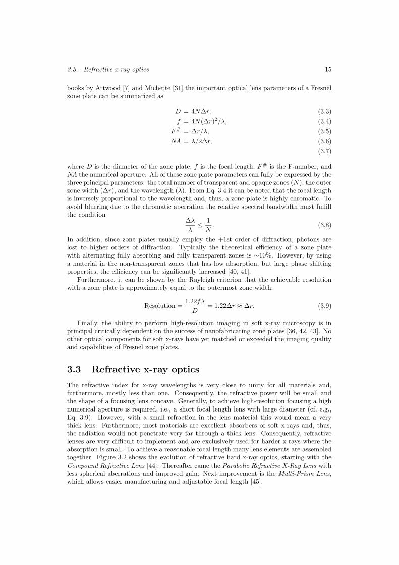
The refractive index for x-ray wavelengths is very close to unity for all materials and,furthermore, mostly less than one. Consequently, the refractive power will be small andthe shape of a focusing lens concave. Generally, to achieve high-resolution focusing a highnumerical aperture is required, i.e., a short focal length lens with large diameter (cf, e.g.,Eq. 3.9). However, with a small refraction in the lens material this would mean a verythick lens. Furthermore, most materials are excellent absorbers of soft x-rays and, thus,the radiation would not penetrate very far through a thick lens. Consequently, refractivelenses are very difficult to implement and are exclusively used for harder x-rays where theabsorption is small. To achieve a reasonable focal length many lens elements are assembledtogether. Figure 3.2 shows the evolution of refractive hard x-ray optics, starting with theCompound Refractive Lens [44]. Thereafter came the Parabolic Refractive X-Ray Lens withless spherical aberrations and improved gain. Next improvement is the Multi-Prism Lens,which allows easier manufacturing and adjustable focal length [45].
16 Chapter 3. X-ray optics
X-rays
(a) The Compound Refractive Lens
X-rays
(b) The Parabolic Refractive Lens
X-rays
(c) The Multi-Prism Lens
Figure 3.2. The evolution of refractive hard x-ray optics
3.4 Reflective x-ray optics
The rest of this chapter is dedicated to a brief description of the principles of reflectivex-ray optics. Multilayer optics, which is used as the condenser of the compact soft x-ray microscope, are covered more in detail. The multilayer condenser is currently themost critical component in the compact x-ray microscope (cf. Chapter 6) since it, with itslow average reflectivity (0.5%), severely limits the number of photons reaching the sampleand, thus, prolongs the exposure time. Several text books have detailed descriptions oftheory, application, and manufacturing of grazing-incidence and multilayer optics, see, e.g.,Refs. [7, 9, 30, 31].
3.4.1 Reflective properties of solid materials
Clearly, the optical characteristics of a material at x-ray wavelengths are guided by thesame classical equations valid for all electromagnetic radiation. However, the outcomecan be very different from what is experienced at visible wavelengths, e.g., total externalreflection instead of total internal reflection. A plane electromagnetic wave traversing amaterial can be described by
E = E0e−i(ωt−kr), (3.10)
where E0 is the amplitude of the electric field, ω the angular frequency, and t is the time.The optical properties of materials enters through the complex propagation vector k, which
3.4. Reflective x-ray optics 17
can be expressed by the complex dispersion relation:
|k| = k =ω
cn, (3.11)
in which c is the speed of light in vacuum and n is the complex refractive index. For x-raysn is usually written as
n = 1− δ + iβ, (3.12)
where δ is the refractive index decrement and β is the absorption index. Both these param-eters are dependent on the wavelength of the x-rays and are related to the complex atomicscattering factor f0 = f0
1 − if02 by
δ =nareλ
2
2πf01 (ω) (3.13)
β =nareλ
2
2πf02 (ω) (3.14)
where na is the average density of atoms and re is the classical electron radius. Althoughthere exist analytical models to calculate estimated values of f 0
1 and f02 , tabulated values
from measurements by Henke et al. [46] are commonly used.Expanding Eq. 3.10 using Eq. 3.11 and Eq. 3.12 reveals the importance and usefulness
of δ and β:
E = E0e−iω(t−r/c)
︸ ︷︷ ︸
vacuum propagation
E0e−i(2πδ/λ)r
︸ ︷︷ ︸
phase shift
E0e−(2πβ/λ)r
︸ ︷︷ ︸
attenuation
. (3.15)
The first factor represents the phase advance of the wave if it had been propagating invacuum, the second factor is the phase shift due to propagation in the material, and thelast is the attenuation of the wave amplitude due to the apsorption in the material.
The reflectance for an electromagnetic wave incident on a boundary between two differentmedia (n1 and n2) is given by the Fresnel equations
Rs =|n1 cosφ1 − n2 cosφ2|2|n1 cosφ1 + n2 cosφ2|2
(3.16)
Rp =|n2 cosφ1 − n1 cosφ2|2|n2 cosφ1 + n1 cosφ2|2
(3.17)
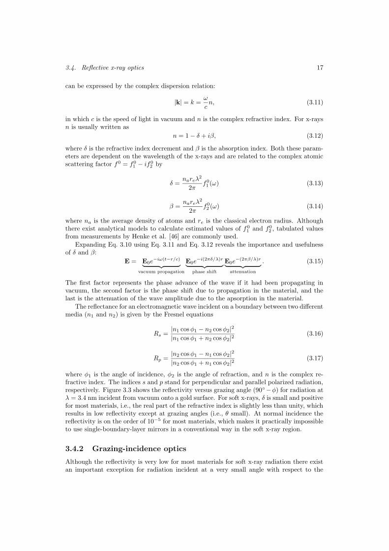
where φ1 is the angle of incidence, φ2 is the angle of refraction, and n is the complex re-fractive index. The indices s and p stand for perpendicular and parallel polarized radiation,respectively. Figure 3.3 shows the reflectivity versus grazing angle (90−φ) for radiation atλ = 3.4 nm incident from vacuum onto a gold surface. For soft x-rays, δ is small and positivefor most materials, i.e., the real part of the refractive index is slightly less than unity, whichresults in low reflectivity except at grazing angles (i.e., θ small). At normal incidence thereflectivity is on the order of 10−5 for most materials, which makes it practically impossibleto use single-boundary-layer mirrors in a conventional way in the soft x-ray region.
3.4.2 Grazing-incidence optics
Although the reflectivity is very low for most materials for soft x-ray radiation there existan important exception for radiation incident at a very small angle with respect to the
18 Chapter 3. X-ray optics
0 10 20 30 40 50 60 70 80 9010
-8
10 -6
10 -4
10 -2
100
Grazing angle [Degrees]
Ref
lect
ivit
y
s
p
Figure 3.3. Reflectivity versus angle for s and p polarized x-rays incident on an Au surface(Data from Ref. [47])
interface surface. Using Snell’s law and neglecting the absorption, the critical angle for thisphenomenon, known as total external reflection, can be calculated as
θc =√2δ. (3.18)
However, due to absorption, the reflectivity will always be slightly less than unity for thecritical and smaller angles. Using a concave spherical surface, total external reflection can beutilized to focus soft x-rays with high efficiency. Unfortunately, at such grazing-incidenceangles the aberrations become severe and/or the numerical aperture is small. This canpartly be overcome by using two or more mirrors, e.g., Kirkpatric-Baez and Wolter optics[48, 49] or using aspherical mirrors. All grazing-incidence optics are, however, difficult touse for high-resolution imaging.
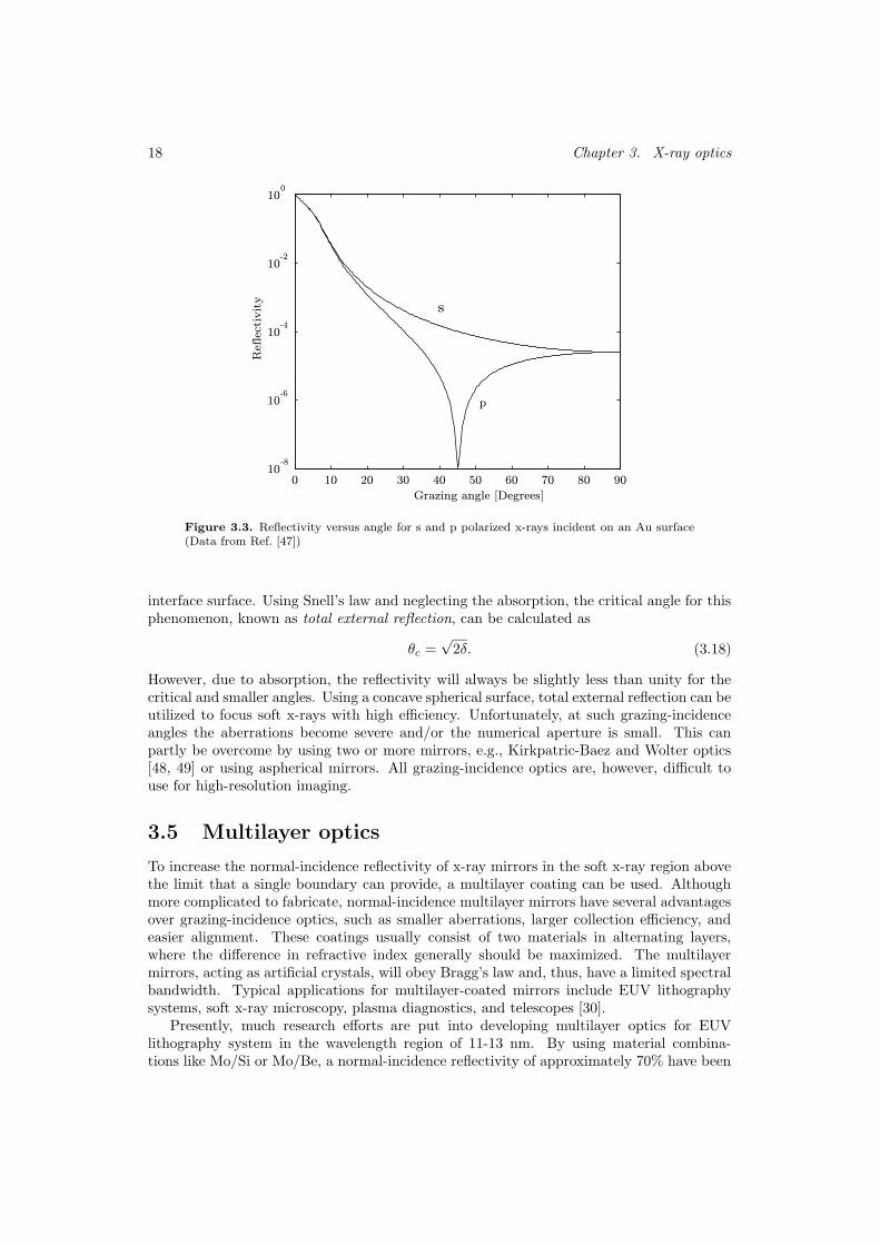
3.5 Multilayer optics
To increase the normal-incidence reflectivity of x-ray mirrors in the soft x-ray region abovethe limit that a single boundary can provide, a multilayer coating can be used. Althoughmore complicated to fabricate, normal-incidence multilayer mirrors have several advantagesover grazing-incidence optics, such as smaller aberrations, larger collection efficiency, andeasier alignment. These coatings usually consist of two materials in alternating layers,where the difference in refractive index generally should be maximized. The multilayermirrors, acting as artificial crystals, will obey Bragg’s law and, thus, have a limited spectralbandwidth. Typical applications for multilayer-coated mirrors include EUV lithographysystems, soft x-ray microscopy, plasma diagnostics, and telescopes [30].
Presently, much research efforts are put into developing multilayer optics for EUVlithography system in the wavelength region of 11-13 nm. By using material combina-tions like Mo/Si or Mo/Be, a normal-incidence reflectivity of approximately 70% have been

3.5. Multilayer optics 19
achieved [50–52]. In the soft x-ray regime, theoretical models indicate that possible normal-incidence reflectivities for Cr/Sc multilayers are 60% near a Sc absorption edge and 40%at λ = 3.374 nm [53–57], which is the wavelength used presently in the compact soft x-raymicroscope. However, due to much more severe requirements on the manufacturing process(primarily interface roughness) the experimental results so far have reached reflectivities of14.5% at the Sc absorption edge [Paper 5].
3.5.1 Multilayer theory
Scattering of electromagnetic radiation occurs at locations where the refractive index changes.At an interface, e.g., between a material and vacuum or between two materials, the scat-tered intensity is very low for soft x-rays at near-normal incidence (cf. previous sections).The idea behind multilayer structures is to choose the thickness of the layers in such a waythat the scattered radiation from each boundary interferes constructively, i.e., the reflectedradiation from each interface adds up without any difference in phase.
Furthermore, since energy and momentum must be conserved in the scattering process,i.e.,
~ωs = ~ωi + ~ωd (3.19)
~ks = ~kkki + ~kkkd (3.20)
where ~ω is the energy and ~kkk is the momentum of the electromagnetic wave, and the indicesi and s label the incident and scattered wave, respectively. The ~ωd and ~kkkd describes astationary charge density distribution “wave” which is the mathematical representation ofthe multilayer structure. Since the structure, i.e., the density distribution, does not moveωd = 0 and, thus, ωs = ωi, resulting in |kkks| = |kkki|. Considering that the multilayer structure”wave” usually is not a simple sinusoid, the more general form of Bragg’s law can be derived:
mλ = 2Λ sin θ, (3.21)
where Λ is the multilayer period (also called d-spacing), λ the wavelength, θ the grazingangle (the angle between the direction of the incident radiation and the surface), and m =(1, 2, 3, ...). Finally, taking the refraction in consideration, Eq. 3.21 turns into
mλ = 2Λ sin θ
√
1− 2δ(λ)
sin2 θ, (3.22)
where δ is the weighted real part of the refractive index for the bilayers. Clearly, Bragg’slaw gives the condition that there exist only one possible value of the multilayer period forconstructive interference, for a given wavelength and angle of incidence (neglecting higherorder reflections). In reality, the multilayer structure acts as a band-pass filter, where thespectral resolving power can roughly be estimated with [58]
λ
∆λ≈ mN, (3.23)
where N is the number of bilayers. The number of bilayers that are required to be depositeddepends on the absorption in the layer materials. For soft x-ray mirrors this value is usuallybetween 200 and 600.

20 Chapter 3. X-ray optics
3.5.2 Optimizing multilayer coatings
Generally, when optimizing multilayer interference coatings many parameters must be con-sidered. This section will only briefly discuss some of them and only in the context ofthe special case that the normal-incidence multilayer condenser in the compact microscoperepresents. Presently, the work is performed at two different wavelengths: 3.374 nm for thecarbon-ion LPP source and 2.48 nm for the nitrogen-ion LPP source [57].
A good starting point is the Fresnel reflection equations (Eq. 3.16 and Eq. 3.17), whichfor normal incidence at a boundary in the multilayer coating merge into
R =|n1 − n2|2|n1 + n2|2
=|(1− δ1 + iβ1)− (1− δ2 + iβ2)|2|(1− δ1 + iβ1) + (1− δ2 + iβ2)|2
≈ (∆δ)2 + (∆β)2
4. (3.24)
Here, δ and β are recognized from the complex refractive index, cf. Eq. 3.12 and the valuesof them are strongly wavelength dependent. At atomic resonances both of them exhibitdiscontinuities which are usually referred to as absorption edges, e.g., see Fig. 3.4. The basic
1 2 3 4 5 6
1 2 3 4 5 6
10-2
10-4
10-3
100 10-2
10-4
10-5
δ β
Wavelength λ [nm]
ScCr
δ
β
Figure 3.4. The wavelength dependence of δ and β for chromium and scandium within thewater window
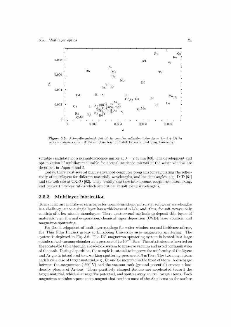
idea is to get maximum reflectivity at each boundary without losing too much radiationinside the layers due to absorption. Consequently, Eq. 3.24 gives a hint that the difference inδ-value between the two materials should be as large as possible at the selected wavelength.The choice of β is more complicated, especially for soft x-rays which could experience verystrong absorption in most materials. Clearly, one of the materials should have a low β,but the β of the other material should be selected under the consideration that ∆β shouldbe maximized without compromising the overall multilayer reflectivity due to attenuation.Figure 3.5 serves as a guide to select materials. The selected material should also bepossible to deposit and the boundaries must be possible to make sufficiently smooth andsharp. Moreover, the materials must be chemically and physically stable, i.e., no chemicalreaction and/or diffusion between the materials can be accepted.
For the first deposition experiments, our collaborators, the Thin Film Physics group atLinkoping University selected boroncarbide (B4C) and tungsten (W). Both materials arestable and have well known magnetron sputtering properties. The boroncarbide, however,contains carbon that is a strong absorbent at the selected wavelength and is thus not thebest choice for the transmission layer. For the continuing experiments Cr/Sc was selected[55, 57, 59], where scandium and chromium have a large difference in δ, cf. Fig. 3.5. However,both of them have relatively low β-values. In this case it was more important to reducethe absorption than to get a large ∆β. A Ni/V multilayer is currently developed as a
3.5. Multilayer optics 21
0 0.002 0.004 0.006 0.008
δ
0
0.002
0.004
0.006
0.008
β Hf
Hg
Ir
Mo
Nb
Os
Pb
Pt
Re
Rh
Ru
Ta
Tl
W
Zr
Au
ZnBi Er
GaGe
Pd Y
Co
Cu
Fe
Ni
CrMnAl
As
B
Be
Ce
In
La NdPr
SeSm
Sn V
Ag
Ba
BrCCa
Cd
Cs
MgRa
S
Sb
Sc
SrTe
Ti
SiP
Figure 3.5. A two-dimensional plot of the complex refractive index (n = 1 − δ + iβ) forvarious materials at λ = 3.374 nm (Courtesy of Fredrik Eriksson, Linkoping University).
suitable candidate for a normal-incidence mirror at λ = 2.48 nm [60]. The development andoptimization of multilayers suitable for normal-incidence mirrors in the water window aredescribed in Paper 3 and 5.
Today, there exist several highly advanced computer programs for calculating the reflec-tivity of multilayers for different materials, wavelengths, and incident angles, e.g., IMD [61]and the web site at CXRO [62]. They usually also take into account roughness, intermixing,and bilayer thickness ratios which are critical at soft x-ray wavelengths.
3.5.3 Multilayer fabrication
To manufacture multilayer structures for normal-incidence mirrors at soft x-ray wavelengthsis a challenge, since a single layer has a thickness of ∼λ/4, and, thus, for soft x-rays, onlyconsists of a few atomic monolayers. There exist several methods to deposit thin layers ofmaterials, e.g., thermal evaporation, chemical vapor deposition (CVD), laser ablation, andmagnetron sputtering.
For the development of multilayer coatings for water-window normal-incidence mirror,the Thin Film Physics group at Linkoping University uses magnetron sputtering. Thesystem is depicted in Fig. 3.6. The DC magnetron sputtering system is hosted in a largestainless steel vacuum chamber at a pressure of 2×10⁻⁷ Torr. The substrates are inserted onthe rotateable table through a load-lock system to preserve vacuum and avoid contaminationof the tank. During deposition, the sample is rotated to improve the uniformity of the layersand Ar gas is introduced to a working sputtering pressure of 3 mTorr. The two magnetronseach have a disc of target material, e.g., Cr and Sc mounted in the front of them. A dischargebetween the magnetrons (-300 V) and the vacuum tank (ground potential) creates a low-density plasma of Ar-ions. These positively charged Ar-ions are accelerated toward thetarget material, which is at negative potential, and sputter away neutral target atoms. Eachmagnetron contains a permanent magnet that confines most of the Ar-plasma to the surface

22 Chapter 3. X-ray optics
of the target material to improve the sputtering process. Some of the sputtered target atomswill reach the surface of the substrate and condence. The deposition rates for making Cr/Scsubstrates were in the order of 0.03 nm/s. A negative bias can be applied to the substrateto attract Ar ions and use the ion bombardment to increase the mobility of the surfaceatoms and thereby smoothen the surface. However, the intermixing between the bilayerscould also increase and reduce the reflectivity. It was found that a solenoid could be used toattract more ions, and therefore the kinetic energy could be lowered while still maintainingsurface mobility. Thus, the intermixing is reduced, because the ions do not crash into thesample. A high flux of low energy ion bombardment limits the intermixing while improvingsurface flatness. A more detailed description on the DC magnetron sputtering process isavailable in Paper 3 and Ref. [59].
Rotateable substrate table
Load-lock valve
Magnetron 2Magnetron 1
Shutters
Bias voltage
Sputtering gas inlet
Solenoid
Figure 3.6. A DC magnetron sputtering system (Courtesy of Fredrik Eriksson, LinkopingUniversity).

Chapter 4
Multilayer mirror
characterization
The properties of a multilayer structure can be described by a number of parameters, wheremultilayer period, individual layer thicknesses, roughness, intermixing, and layer densityare among the most common and important ones. All these parameters will strongly in-fluence the final reflectivity of the multilayer mirror. Accurate characterization methodsare essential to gain control of all these parameters. Several different methods like hardx-ray diffraction/reflectometery (XRD), soft x-ray reflectometry, transmission electron mi-croscopy (TEM), and atomic force microscopy (AFM) have been used during the multilayerdevelopment process.
4.1 Hard x-ray diffraction
Hard x-ray diffraction is probably the most widely used technique to study the internalstructure of solid materials [63]. During the development of multilayer mirrors for the com-pact soft x-ray microscope condenser system the nanostructural properties of the multilayerswere obtained from hard x-ray low-angle reflectivity measurements at the fabrication site inLinkoping. The diffractometer has a decoupled detector (2θ) and sample (ω) axes so thatboth coupled ω − 2θ scans and ω-rocking curves could be performed. The instrument hasa copper-anode source generating line emission at λ = 0.154 nm (Cu Kα), cf. Fig. 1.1.
Specular hard x-ray reflectivity measurements from 0.7 − 20 (2θ) were performed onall samples. The multilayer period was calculated from the position of the Bragg reflectionsand individual layer thickness and interface widths were determined by fitting a theoreticalmodel to the experimental data. Non-specular transverse ω-rocking scans for constant 2θ-values, corresponding to the first Bragg peak reflection of the investigated multilayers, werealso performed. These scans reveal how much of the x-rays that are specularly reflected anddiffusively scattered, and hence gives qualitative information about the interface roughness.
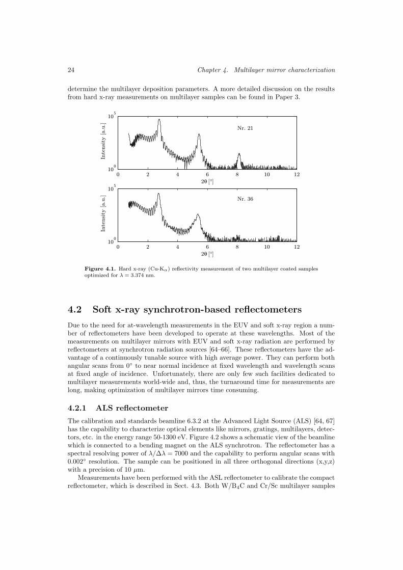
Two selected hard x-ray measurements on multilayer samples deposited at differentconditions are shown in Fig. 4.1, where the absolute reflectivity is proportional to theintensity scale in the diagram. However, when comparing these hard x-ray reflectivitymeasurements with corresponding measurements performed with the compact soft x-rayreflectometer they contradict each other, see Sect. 4.3.3. Therefore, it can be concludedthat measurement at the intended wavelength will provide most reliable information to
23
24 Chapter 4. Multilayer mirror characterization
determine the multilayer deposition parameters. A more detailed discussion on the resultsfrom hard x-ray measurements on multilayer samples can be found in Paper 3.
0 2 4 6 8 10 1210
0
105
2θ [°]
Inte
nsi
ty [a.u
.]
0 2 4 6 8 10 1210
0
105
2θ [°]
Inte
nsi
ty [a.u
.]
Nr. 21
Nr. 36
Figure 4.1. Hard x-ray (Cu-Kα) reflectivity measurement of two multilayer coated samplesoptimized for λ = 3.374 nm.
4.2 Soft x-ray synchrotron-based reflectometers
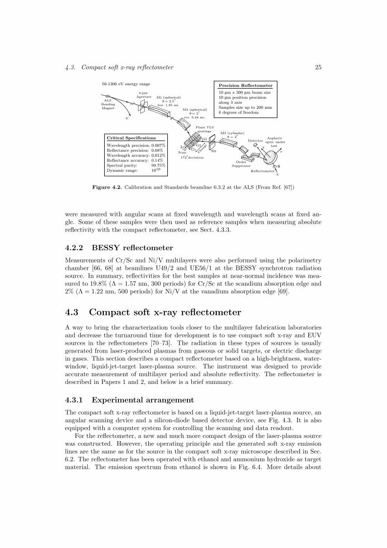
Due to the need for at-wavelength measurements in the EUV and soft x-ray region a num-ber of reflectometers have been developed to operate at these wavelengths. Most of themeasurements on multilayer mirrors with EUV and soft x-ray radiation are performed byreflectometers at synchrotron radiation sources [64–66]. These reflectometers have the ad-vantage of a continuously tunable source with high average power. They can perform bothangular scans from 0 to near normal incidence at fixed wavelength and wavelength scansat fixed angle of incidence. Unfortunately, there are only few such facilities dedicated tomultilayer measurements world-wide and, thus, the turnaround time for measurements arelong, making optimization of multilayer mirrors time consuming.
4.2.1 ALS reflectometer
The calibration and standards beamline 6.3.2 at the Advanced Light Source (ALS) [64, 67]has the capability to characterize optical elements like mirrors, gratings, multilayers, detec-tors, etc. in the energy range 50-1300 eV. Figure 4.2 shows a schematic view of the beamlinewhich is connected to a bending magnet on the ALS synchrotron. The reflectometer has aspectral resolving power of λ/∆λ = 7000 and the capability to perform angular scans with0.002 resolution. The sample can be positioned in all three orthogonal directions (x,y,z)with a precision of 10 µm.
Measurements have been performed with the ASL reflectometer to calibrate the compactreflectometer, which is described in Sect. 4.3. Both W/B4C and Cr/Sc multilayer samples
4.3. Compact soft x-ray reflectometer 25
ALSBendingMagnet
e-
4-jawAperture M1 (spherical)
θ = 2.5o
hor. 1.85 mr.
M2 (spherical) θ = 2
o
ver. 0.44 mr.
M3 (cylinder) θ = 2
o
Plane VLSgratings
172odeviation
Scan Slit
Cha
nge
G1
G2
G3
OrderSuppressor
x
y
Detector
θ
50-1300 eV energy range
Critical Specifications
z
Reflectometer
Asphericoptic under
testλ
Precision Reflectometer
Wavelength precision:Reflectance precision:Wavelength accuracy:Reflectance accuracy:Spectral purity:Dynamic range:
0.007%0.08%0.012%0.14%99.75%1010
10 µm x 300 µm beam size10 µm position precisionalong 3 axisSamples size up to 200 mm6 degrees of freedom
Figure 4.2. Calibration and Standards beamline 6.3.2 at the ALS (From Ref. [67])
were measured with angular scans at fixed wavelength and wavelength scans at fixed an-gle. Some of these samples were then used as reference samples when measuring absolutereflectivity with the compact reflectometer, see Sect. 4.3.3.
4.2.2 BESSY reflectometer
Measurements of Cr/Sc and Ni/V multilayers were also performed using the polarimetrychamber [66, 68] at beamlines U49/2 and UE56/1 at the BESSY synchrotron radiationsource. In summary, reflectivities for the best samples at near-normal incidence was mea-sured to 19.8% (Λ = 1.57 nm, 300 periods) for Cr/Sc at the scandium absorption edge and2% (Λ = 1.22 nm, 500 periods) for Ni/V at the vanadium absorption edge [69].
4.3 Compact soft x-ray reflectometer
A way to bring the characterization tools closer to the multilayer fabrication laboratoriesand decrease the turnaround time for development is to use compact soft x-ray and EUVsources in the reflectometers [70–73]. The radiation in these types of sources is usuallygenerated from laser-produced plasmas from gaseous or solid targets, or electric dischargein gases. This section describes a compact reflectometer based on a high-brightness, water-window, liquid-jet-target laser-plasma source. The instrument was designed to provideaccurate measurement of multilayer period and absolute reflectivity. The reflectometer isdescribed in Papers 1 and 2, and below is a brief summary.
4.3.1 Experimental arrangement
The compact soft x-ray reflectometer is based on a liquid-jet-target laser-plasma source, anangular scanning device and a silicon-diode based detector device, see Fig. 4.3. It is alsoequipped with a computer system for controlling the scanning and data readout.
For the reflectometer, a new and much more compact design of the laser-plasma sourcewas constructed. However, the operating principle and the generated soft x-ray emissionlines are the same as for the source in the compact soft x-ray microscope described in Sec.6.2. The reflectometer has been operated with ethanol and ammonium hydroxide as targetmaterial. The emission spectrum from ethanol is shown in Fig. 6.4. More details about

26 Chapter 4. Multilayer mirror characterization
Figure 4.3. A compact soft x-ray reflectometer based on a line-emitting laser plasma source
the principles for the liquid-jet and liquid-droplet laser-plasma sources can be found inRef. [18, 74, 75].
The scanning device consists of stepper motor and a gear to provide the θ-2θ motion ofthe sample and detector, respectively. It is located in a large vacuum chamber, which is con-nected to the source chamber through a valve. The compact reflectometer is equipped withtwo detectors, one located on the scanning device for measuring on the multilayer sampleand the other mounted stationary as a reference detector monitoring the source intensity.The two detectors are two identical assemblies of a soft x-ray silicon photodiode (AXUV-5,IRD Inc.) and a charge sensitive amplifier (A250, Amptek Inc.). The output signal fromthe amplifiers is fed to a digital oscilloscope (Tektronix Inc., TDS 620B) with averagingand measuring capabilities and then the measurements are transferred to a computer forstorage. The computer is also equipped with an I/O-card that controls the motion of thestepper motor, and thereby the scanning of the multilayer sample.
4.3.2 Multilayer period measurements
When manufacturing multilayer mirrors for the condenser in the compact soft x-ray micro-scope it is vital that the multilayer period can be accurately measured and controlled. Sincethe wavelength is fixed to one selected emission line from the source and the geometry of themicroscopy also is fixed and requires the incident angle to be near normal, the multilayerperiod has only one possible value according to Eq. 3.21. During the manufacturing processthis value has to be met with high precision. The required accuracy of the multilayer periodcan be estimated from
λ
∆λ=
Λ
∆Λ, (4.1)
which is obtained by dividing Eq. 3.21 by the differentiated version of the same equation.Assuming a mirror bandwidth of Λ/∆Λ = 80 (FWHM, W/B4C) and wavelength of λ =
4.3. Compact soft x-ray reflectometer 27
3.374 nm, a deviation of only 0.01 nm would reduce the reflectivity to half of is maximumvalue. To meet this requirement on measuring accuracy with the compact reflectometer aspecial multi-line method was developed [Paper 2]. This algorithm provide a measurementaccuracy of 0.001 nm in special cases.
4.3.3 Absolute reflectivity measurements
The main goal with the development of new multilayer mirrors for the condenser in thecompact soft x-ray microscope is to increase the efficiency and thus the reflectivity of themultilayer structure, and thereby reducing the exposure times. The reflectivity and theshape of the reflectivity curve also contain much information about properties of the internalmultilayer structure like intermixing, roughness, etc.
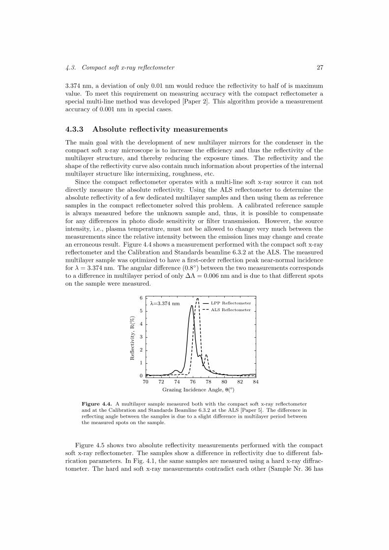
Since the compact reflectometer operates with a multi-line soft x-ray source it can notdirectly measure the absolute reflectivity. Using the ALS reflectometer to determine theabsolute reflectivity of a few dedicated multilayer samples and then using them as referencesamples in the compact reflectometer solved this problem. A calibrated reference sampleis always measured before the unknown sample and, thus, it is possible to compensatefor any differences in photo diode sensitivity or filter transmission. However, the sourceintensity, i.e., plasma temperature, must not be allowed to change very much between themeasurements since the relative intensity between the emission lines may change and createan erroneous result. Figure 4.4 shows a measurement performed with the compact soft x-rayreflectometer and the Calibration and Standards beamline 6.3.2 at the ALS. The measuredmultilayer sample was optimized to have a first-order reflection peak near-normal incidencefor λ = 3.374 nm. The angular difference (0.8) between the two measurements correspondsto a difference in multilayer period of only ∆Λ = 0.006 nm and is due to that different spotson the sample were measured.
LPP Reflectometer
ALS Reflectometer
λ=3.374 nm
70 72 74 76 78 80 82 84
Grazing Incidence Angle, θ(o)
0
1
2
3
4
5
6
Ref
lect
ivity, R
(%)
Figure 4.4. A multilayer sample measured both with the compact soft x-ray reflectometerand at the Calibration and Standards Beamline 6.3.2 at the ALS [Paper 5]. The difference inreflecting angle between the samples is due to a slight difference in multilayer period betweenthe measured spots on the sample.
Figure 4.5 shows two absolute reflectivity measurements performed with the compactsoft x-ray reflectometer. The samples show a difference in reflectivity due to different fab-rication parameters. In Fig. 4.1, the same samples are measured using a hard x-ray diffrac-tometer. The hard and soft x-ray measurements contradict each other (Sample Nr. 36 has

28 Chapter 4. Multilayer mirror characterization
20 25 30 35 40 450
1
2
3
4
5
Grazing angle [°]
Ref
lect
ivit
y [%
]
20 25 30 35 40 450
1
2
3
4
5
Grazing angle [°]
Ref
lect
ivit
y [%
]Nr. 21
Nr. 36
Figure 4.5. Absolute reflectivity measurements of two Cr/Sc samples performed with thecompact soft x-ray reflectometer. The measurements were calibrated with a reference samplemeasured at ALS
a higher soft x-ray reflectivity than Nr. 21 despite that hard x-ray reflectivity indicates theopposite). Clearly, this shows the importance of performing at-wavelength measurementsfor characterization purposes. The difference between hard and soft x-ray measurementscan be explained by different sensitivity of the two methods to layer roughness. A moredetailed discussion is found in Paper 3.
4.4 Conclusions
Presently the development of a new multilayer condenser mirror is concentrated on opti-mizing the Cr/Sc and Ni/V deposition process. Recent results show that a reflectivity of atleast 5% is possible to achieve [Paper 5] for a Cr/Sc normal-incidence mirror at the 3.374 nmemission line. Also, reflectivities up to 14.5% is achievable at near-normal incidence closeto the scandium absorption edge indicating low layer intermixing and interface roughness.The contradicting results from hard and soft x-ray measurements shows the importanceof at-wavelength measurements. The Thin Film Physics group at Linkoping University isnow preparing for full-scale deposition on spherical substrates that later can be used ascondensers in the compact soft x-ray microscope. The group is also working on multilayercoatings with Ni/V and other materials suitable for the λ = 2.48 nm emission line in theliquid nitrogen source [69].

Chapter 5
Characteristics of soft x-ray
microscopy
5.1 Introduction
The use of x-rays for microscopy purposes was suggested (Goby, 1913) shortly after Rontgen’sdiscovery of x-rays. Soft x-ray microscopy in the water-window (2.3-4.4 nm) was proposedin 1952 by Wolter [76]. However, at that time it was not possible to experimentally imple-ment the idea due to the lack of suitable soft x-ray sources and optics. The first successfulattempt to perform high-resolution x-ray microscopy was made in 1976 at a synchrotronsource in combination with diffractive x-ray optics [5]. This chapter discusses the propertiesof soft x-ray microscopy and gives a brief overview of the microscopes that are in operationtoday.
5.2 Resolution and contrast
Resolution and contrast are the two most important parameters when evaluating differentmicroscopy techniques. They are closely linked together and are measures of how muchinformation that may be obtained from an imaging process.
A strong motivation to develop soft x-ray microscopy is that it has potential to provide amuch higher resolution than visible light microscopy [77]. The Rayleigh resolution criterionstates that the minimal distance between two resolved object points is
∆rRayl. =0.61λ
NA, (5.1)
where λ is the wavelength and NA is the numerical aperture. For wavelengths in thewater-window this would suggest a theoretical resolution of a few nm provided high-NAoptics could be fabricated. However, the resolution is presently limited to 20-25 nm by thecurrently available diffractive optics that are used as imaging objectives, see, e.g., Refs. [37,38, 41, 78].
The contrast mechanism when using electromagnetic radiation with shorter wavelengths,e.g., x-rays, is rather complicated. X-ray photons interact with matter by photoelectricabsorption, and elastic and inelastic (Compton) scattering. For soft x-ray wavelengths thedominating process is photoelectric absorption. The cross section for this process is strongly
29
30 Chapter 5. Characteristics of soft x-ray microscopy
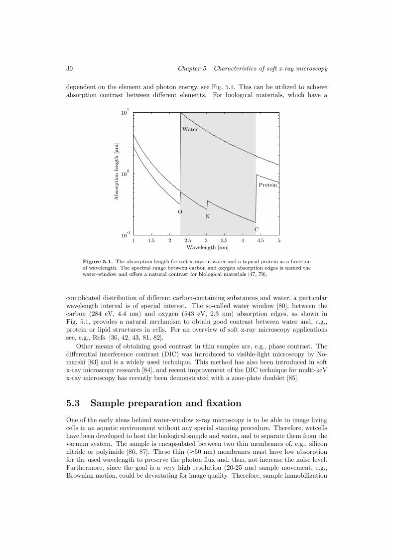
dependent on the element and photon energy, see Fig. 5.1. This can be utilized to achieveabsorption contrast between different elements. For biological materials, which have a
1 1.5 2 2.5 3 3.5 4 4.5 510
-1
100
101
Wavelength [nm]
Abso
rpti
on len
gth
[µm
]
Water
Protein
O N
C
Figure 5.1. The absorption length for soft x-rays in water and a typical protein as a functionof wavelength. The spectral range between carbon and oxygen absorption edges is named thewater-window and offers a natural contrast for biological materials [47, 79].
complicated distribution of different carbon-containing substances and water, a particularwavelength interval is of special interest. The so-called water window [80], between thecarbon (284 eV, 4.4 nm) and oxygen (543 eV, 2.3 nm) absorption edges, as shown inFig. 5.1, provides a natural mechanism to obtain good contrast between water and, e.g.,protein or lipid structures in cells. For an overview of soft x-ray microscopy applicationssee, e.g., Refs. [36, 42, 43, 81, 82].
Other means of obtaining good contrast in thin samples are, e.g., phase contrast. Thedifferential interference contrast (DIC) was introduced to visible-light microscopy by No-marski [83] and is a widely used technique. This method has also been introduced in softx-ray microscopy research [84], and recent improvement of the DIC technique for multi-keVx-ray microscopy has recently been demonstrated with a zone-plate doublet [85].
5.3 Sample preparation and fixation
One of the early ideas behind water-window x-ray microscopy is to be able to image livingcells in an aquatic environment without any special staining procedure. Therefore, wetcellshave been developed to host the biological sample and water, and to separate them from thevacuum system. The sample is encapsulated between two thin membranes of, e.g., siliconnitride or polyimide [86, 87]. These thin (≈50 nm) membranes must have low absorptionfor the used wavelength to preserve the photon flux and, thus, not increase the noise level.Furthermore, since the goal is a very high resolution (20-25 nm) sample movement, e.g.,Brownian motion, could be devastating for image quality. Therefore, sample immobilization

5.5. Synchrotron-based soft x-ray microscopes 31
is required and this can be done by letting the cell adhere to the membrane surface andstabilize it with some chemical fixation such as glutaraldehyde.
Another frequently used method is cryogenic fixation, which has been adopted fromelectron microscopy. Here, the sample is plunge frozen into liquid ethane at a temperatureof liquid nitrogen. The freezing process must be very rapid to avoid crystallization of thewater, which would destroy the sample [88].
Using sample preparation techniques it is also possible to increase contrast, e.g., byusing colloidal gold labeling to enhance certain cell structures like membranes, microtubulenetwork or actin filaments [89, 90].
5.4 Radiation damage
Soft x-ray photons have sufficient energy to ionize atoms and, thus, break chemical bonds.The sample will receive a large radiation dose, typically 105 to 106 Gray, during exposure.However, unfixed hydrated cells show structural alterations already at a dose of 104 Gray[34]. Clearly, no biological material will ever survive an exposure in a soft x-ray microscopeand low-dose experiments show that the dose required to get a 10% cell survival is D10 =2.2 Gray at 0.28 keV radiation [91]. Furthermore, in water the soft x-ray radiation ionizeswater molecules and create free radicals. These free radicals could attack and destroy abiological specimen. If the biological samples are chemically fixed they withstand up toapprox. 106 Gray [34, 92] and if they are cryogenically fixated a dose of 1010 Gray [34, 88]will not introduce any morphological changes. Finally, by using phase contrast techniquesinstead of absorption contrast the radiation dose may be reduced.
5.5 Synchrotron-based soft x-ray microscopes
Today, the few soft x-ray microscopes that are in operation are based on synchrotron sources.This section gives a very brief description of the three most successful soft x-ray microscopyprojects.
5.5.1 Transmission x-ray microscopy
A typical experimental arrangement for a transmission x-ray microscope (TXM) is shownin Fig. 5.2. The soft x-rays are directed from a synchrotron radiation source onto thecondenser zone plate. This lens focuses the radiation onto the sample and thereby providesthe illumination. A diffraction-order-sorting and monochromator aperture placed at thesample location sorts out the first diffraction order from the condenser zone plate. A microzone plate then images the sample on a soft x-ray-sensitive camera (CCD).
The Institute for X-Ray Physics in Gottingen, Germany, which pioneered soft x-raymicroscopy is now operating their transmission x-ray microscope at the BESSY II syn-chrotron facility, Berlin [5, 93–95]. The microscope utilizes a high-brigthness undulatorsource in combination with an off-axis transmission zone plate monchromator to achievea high degree of monochromaticity and a pair of rotating mirrors to match the numericalaperture of the micro zone plate. Applications for this microscope cover a wide range oftopics, e.g., biology, colloidal physics, enviromental and soil science.
The Center for X-Ray Optics (CXRO), Berkeley Lab, operates a full-field soft x-raymicroscope at beamline 6.1.2 on the Advanced Light Source (ALS) synchrotron facility[78, 89, 96, 97]. The microscope can achieve a resolution of 25 nm and can tune the energyof the photons between 250-850 eV. The exposure time is typically a few seconds for 1000

32 Chapter 5. Characteristics of soft x-ray microscopy
Condenser zone plate
Sample and order sorting aperture
Objective zone plate
Detector(CCD)
X-rays
Figure 5.2. Schematic figure of a high-resolution transmission x-ray microscope (TXM)
photons/pixel [98]. The applications include e.g., cell biology, magnetic materials, andmaterial sciences.
5.5.2 Scanning soft x-ray microscopy
At Brookhaven’s National Synchrotron Light Source (NSLS) the x-ray optics and mi-croscopy group at SUNY Stony Brook, USA operates a scanning soft x-ray microscope[99, 100]. This type of microscope uses only one zone plate and spatially coherent illumi-nation from, preferably, an undulator source. The zone plate provides a focal spot on thesample with a size limited by the resolution of the zone plate. An order-sorting apertureand the central stop of the zone plate will stop all diffraction orders except the first. A fastx-ray detector then detects the photons transmitted through the sample at that focal spot.Since there are no optical components, e.g., a micro zone plate, between the sample anddetector the losses will be minimal and the radiation dose lower than in the TXM case. Tocreate an image the sample has to be scanned in two dimensions. Furthermore, the scanningmicroscope has the ability to perform X-ray Absorption Near Edge Structure (XANES),which is an important method to image molecular or element distribution in a sample [101].
5.6 Final remarks
The growing interest in high-resolution imaging in the x-ray region has lead to developmentof various types of x-ray microscopy on several synchrotron radiation facilities. Othersynchrotron-based x-ray microscopy groups can be found at, e.g., ESRF, Grenoble, France[102], APS, Argonne National Laboratory, USA [103], and SPring-8, Japan [104].
Furthermore, there exists other types of x-ray microscopy techniques, e.g., contact mi-croscopy and holographic microscopy. In contact x-ray microscopy [105, 106] the sample inplaced directly onto an x-ray sensitive photoresist, e.g., polymethylmethacrylate (PMMA).The sample-resist combination is then exposed to x-rays and after development the im-age can be retrieved by electron microscopy or atomic force microscopy (AFM). In Fouriertransform x-ray holography, the scattered x-rays from an object is made to interfere witha spherical reference wave. The interference pattern is recorded by a charge-coupled devicecamera and final image is obtained by numerical reconstruction [107].
Traditionally, the source for soft x-ray microscopy is a bending magnet or undulatoron a synchrotron. This is an obstacle, making it difficult to transfer the microscopy tonormal-sized biological laboratories. Therefore, efforts have been made to design a compactsoft x-ray microscope. The next chapter will briefly describe such a project.

Chapter 6
Compact soft x-ray microscopy
6.1 Introduction
Although most of the experimental arrangement of a synchrotron x-ray microscope is oftable-top dimensions, the x-ray source certainly is not. This means that all users have tobring their samples to the microscope and the synchrotron radiation facility to do experi-ments, which in many cases is neither convenient nor possible. The development of a com-pact soft x-ray microscope would make it possible to place the instrument in the normal-sizebiological or material sciences laboratory. Previous attempts to develop a table-top x-raymicroscope have usually had problems with too low source brightness and/or inefficientcondenser optics [20, 36]. The division for Biomedical and X-Ray Physics, Royal Instituteof Technology (KTH), Sweden is currently developing a table-top instrument based on asoft x-ray liquid-jet laser-plasma source and are putting efforts in optimizing the bright-ness of the source and increasing the efficiency of the condenser. This compact soft x-raymicroscope is presented in, e.g., Ref. [108, 109] and Paper 4.
The currently operational version, depicted in Fig 6.1, offers a stable mechanical con-struction, easy alignment of the x-ray optics, and an easy-to-use sample handling system.That type of requirements must be fulfilled to enable the system to be used for real appli-cations, e.g., in biology.
The compact soft x-ray microscope can basically be divided into four critical subsystems:radiation source, condenser, sample and micro zone plate stage, and CCD detector. Theseare described below. The microscope has a modular design to allow easier modificationsof parts and allow major future reconfigurations, e.g., implementing a cryo sample stage.Each module is mounted on a robust vertical base plate and most of the parts are madeof aluminum to avoid misalignment due to thermal drift. The microscope can be dividedinto three vacuum systems, which can be separated from each other by vacuum valves. Thesource and condenser occupy the lower one and the sample-stage chamber is designed to bea load-lock system to allow for quick sample exchange. The detector is placed in the uppervacuum system.
A new version of compact soft x-ray microscope is also under development, see Fig. 6.2.This version is intended to use a liquid-nitrogen laser-plasma source at λ = 2.4 nm andwill have to option to use a condenser zone plate. The current status of this project is thatthe liquid-nitrogen laser-plasma source is fully operational, multilayers for the sphericalcondenser mirror is pursued, and a first test of condenser zone plate has been done, see thefollowing sections.
33
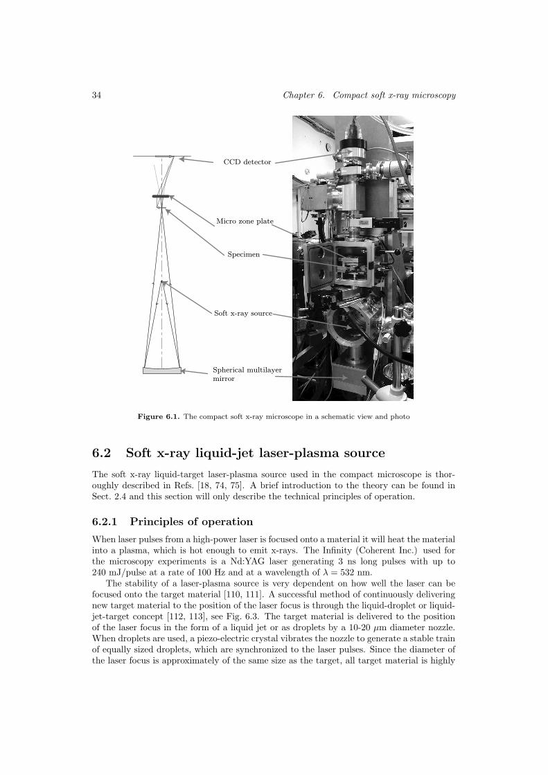
34 Chapter 6. Compact soft x-ray microscopy
Spherical multilayer
mirror
Soft x-ray source
Specimen
Micro zone plate
CCD detector
Figure 6.1. The compact soft x-ray microscope in a schematic view and photo
6.2 Soft x-ray liquid-jet laser-plasma source
The soft x-ray liquid-target laser-plasma source used in the compact microscope is thor-oughly described in Refs. [18, 74, 75]. A brief introduction to the theory can be found inSect. 2.4 and this section will only describe the technical principles of operation.
6.2.1 Principles of operation
When laser pulses from a high-power laser is focused onto a material it will heat the materialinto a plasma, which is hot enough to emit x-rays. The Infinity (Coherent Inc.) used forthe microscopy experiments is a Nd:YAG laser generating 3 ns long pulses with up to240 mJ/pulse at a rate of 100 Hz and at a wavelength of λ = 532 nm.
The stability of a laser-plasma source is very dependent on how well the laser can befocused onto the target material [110, 111]. A successful method of continuously deliveringnew target material to the position of the laser focus is through the liquid-droplet or liquid-jet-target concept [112, 113], see Fig. 6.3. The target material is delivered to the positionof the laser focus in the form of a liquid jet or as droplets by a 10-20 µm diameter nozzle.When droplets are used, a piezo-electric crystal vibrates the nozzle to generate a stable trainof equally sized droplets, which are synchronized to the laser pulses. Since the diameter ofthe laser focus is approximately of the same size as the target, all target material is highly

6.2. Soft x-ray liquid-jet laser-plasma source 35
Cooling device for
liquid nitrogen
Entrance for
laser beam
LPP source vacuum
chamber
Figure 6.2. The first part of the liquid-nitrogen LPP microscopy is completed; the liquid-nitrogen source is now fully operational.
ionized. Thus, the source will not emit debris in form of clusters and fragments of targetmaterial [114]. The size of the emitting source is typically 15-25 µm [115].
Liquid-jet laser plasma Liquid-droplet laser plasma
Nozzle
High-intensity laser pulse
Liquid
Figure 6.3. Laser pulses from a high-power laser is focused onto a material and it will heatthe material into a plasma, which is hot enough to emit x-rays. The Laser plasma source caneither be operated in liquid-jet or droplet mode.
Unfortunately, the previously used commercial ink-jet glass nozzles1 have a limited rangeof usable liquids. The materials inside the nozzle assembly dissolved when it came in contactwith ethanol and created jet instabilities. A new nozzle design and fabrication method hastherefore been developed which is based on synthetic fused silica capillary, see Paper 7.The capillary tubing and filters are compatible with most common liquids except for somestrong acids and allows that a nozzle with suitable taper and diameter can be manufacturedat one of the ends. In addition, the new nozzle design has also been found very suitable fora liquid-nitrogen laser-plasma source [116].
6.2.2 Characteristics of the x-ray emission
The emission spectrum from a laser-plasma source will depend on laser pulse energy, pulselength, and target material. For soft x-ray microscopy in the water-window, the line emissionfrom hydrogen- and helium-like carbon and nitrogen ions is particularly suitable since thestrongest emission lines from these ions lie within this wavelength region (2.3 − 4.4 nm),
1Siemens-Elema AB, Stockholm, Sweden

36 Chapter 6. Compact soft x-ray microscopy
cf. Fig. 6.4. The bandwidth of an emission line is typically λ/∆λ > 500 [117] and theintensities of the strongest lines are of the order of 1011 to 1012 photons/(sr×pulse×line).Finally, since the emission lines originate from the energy levels in the ions, the laser-plasmasource has an extremely high spectral stability.
1 1.5 2 2.5 3 3.5 4 4.50
0.1
0.2
0.3
0.4
0.5
0.6
0.7
0.8
0.9
1
Wavelength [nm]
Inte
nsi
ty [a.u
.]
C V
1s2-1s2p
C VI
1s-2p
C V
1s2-1s3p
C VI
1s-3p
C VI
1s-4p
O VII
1s2-1s2p
O VIII
1s-2p
O VIII
1s-3p
Figure 6.4. Emission spectrum from ethanol target. Several strong emission lines lie withinthe water window (2.3–4.4 nm).
The liquid-nitrogen source emits photons with λ = 2.48 nm which is close to the oxygenabsorption edge inside the water window, see Fig. 5.1. This wavelength has approx. 4×better transmission through 10 µm water than the λ = 3.374 nm emission line from car-bon ions and would, thus, reduce exposure times and/or reduce photon noise in the image.Furthermore, the liquid-nitrogen source eliminates the risk of carbon contamination of sen-sitive soft x-ray optics. However, the implementation of the condenser optics becomes morecomplicated, due to the shorter wavelength, see Sect. 6.3.
6.3 Condenser arrangement
The condenser is currently the most critical component in a compact soft x-ray microscopysystem. Although the laser-plasma source described in the previous section produces a highphoton flux, the emitted photons are almost uniformly distributed into 4π sr solid angle.This type of source therefore requires an effective condenser system to transfer as manyphotons as possible to the sample, see Fig. 6.5. The first choice fell on a spherical, normal-incidence multilayer-mirror condenser [118], since it has several attractive properties suchas: small aberrations, easy alignment, and wavelength selectivity. More on the developmentof this multilayer mirror can be found in chapter 3. In addition, the possibility of using acondenser zone plate is presently under evaluation.
6.3.1 Normal-incidence spherical multilayer condenser
The multilayer condenser mirror presently used in the compact microscope consists of 200bi-layers of W/B4C deposited on a spherical SiO2 substrate and with a multilayer periodsuitable for λ = 3.374 nm [118]. Since it is positioned 263 mm below the source (see Fig. 6.1)and has a diameter of 58 mm, the collecting solid angle is Ω = 0.03 sr taking the central
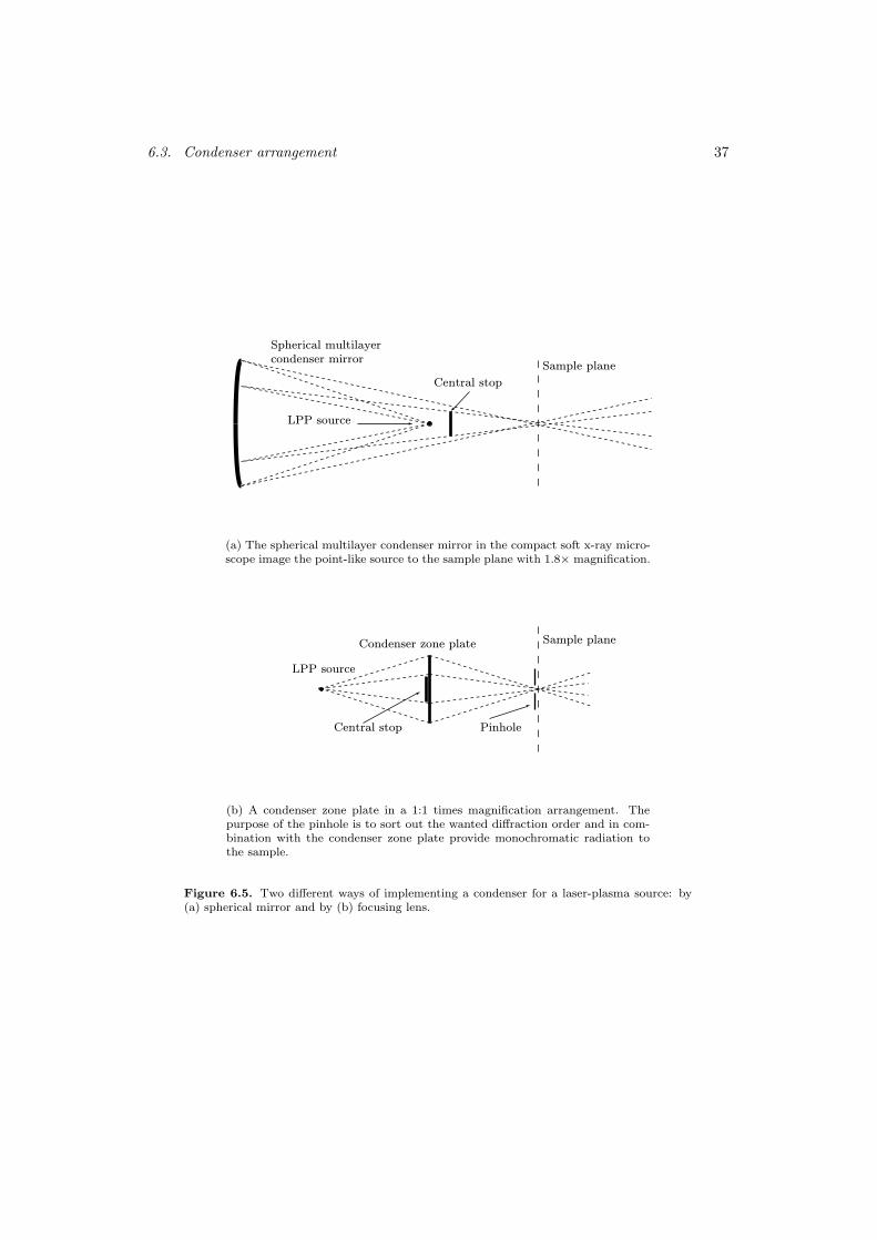
6.3. Condenser arrangement 37
Spherical multilayer
condenser mirror
LPP source
Central stop
Sample plane
(a) The spherical multilayer condenser mirror in the compact soft x-ray micro-scope image the point-like source to the sample plane with 1.8× magnification.
LPP source
Central stop
Sample planeCondenser zone plate
Pinhole
(b) A condenser zone plate in a 1:1 times magnification arrangement. Thepurpose of the pinhole is to sort out the wanted diffraction order and in com-bination with the condenser zone plate provide monochromatic radiation tothe sample.
Figure 6.5. Two different ways of implementing a condenser for a laser-plasma source: by(a) spherical mirror and by (b) focusing lens.

38 Chapter 6. Compact soft x-ray microscopy
stop into account. The theoretical reflectivity for W/B4C at the wavelength 3.374 nm isR = 5.5% and, thus, the total effective collection solid angle (Ω × R) would be approx.2× 10−3 sr (no filters included in calculations).
However, although the peak reflectivity is 3% at certain locations the average reflectivityfor the used area is of the order of 0.5%. Furthermore, only 10% of the reflected photonsreach the expected focal spot of 25 µm, while the rest are spread out over a large area (flare)[118]. This is believed to be due to mid-spatial frequency surface figure errors, which is notpossible to detect with visible interferometry. The present value of the effective collectionsolid angle of the condenser is therefore approx. 2× 10⁻⁵ sr.
Finally, using the Cr/Sc multilayer, described in Paper 5, with presently 5-6% reflectivitythe number of photons delivered to the sample plane would increase by a factor of 10. Thereare indications that the flare should be lower for Cr/Sc and, thus, the gain would be evenlarger. Unfortunately, high reflectivity usually corresponds to a narrow bandwidth andit could be hard to achieve the correct multilayer period to match the narrow emissionline coming from the LPP source over the full area of the condenser mirror. In addition,although 2% reflectivity have been achieved at λ = 2.4 nm (Ni/V Ref. [69]) the task ofdepositing large spherical mirrors with a uniform and correct multilayer period for suchshort period is extremely difficult.
6.3.2 Condenser zone plate
An alternative to a spherical condenser mirror for λ = 2.4 nm could be a condenser zoneplate (CZP). This approach is currently pursued for the new compact soft x-ray microscope[119]. Initially, two different schemes have been chosen, where the parameters have beenselected due to practical reasons regarding the laser plasma source and available nanofabri-cation techniques. The condenser concept is shown in Fig. 6.5(b), in which the CZP collectsthe photons from the laser plasma and focuses them onto the sample with a 1:1 times mag-nification. The first scheme is a zone plate used in 1st diffraction order with a diameterof 4.5 mm and a focal length of 90 mm. The theoretical diffraction efficiency would beη ≈ 20% and in combination with the collecting solid angle, Ω = 1.5 × 10⁻⁴ sr, the totaleffective collection solid angle (η×Ω) would be approx. 3× 10⁻⁵ sr. This includes the cen-tral stop to achieve the required hollow cone illumination, but does not taking into accountabsorption in filters and CZP substrate. The next arrangement would be to use the sametype of zone plate in 2nd order 1:1 imaging. The loss of efficiency due to utilizing a higherdiffraction order would be compensated by the larger collection solid angle. However, thesize of the central stop could be made smaller without losing field of view and a gain ofalmost 3 compared to the first proposal could be expected.
Although the condenser zone plate should be inferior to a multilayer condenser mirrordue to the possibility to have a much larger collection solid angle of the latter, there existseveral advantages with a zone plate. First, the zone plate can operate over a wide rangeof wavelengths within the water window compared to a single for the multilayer mirror.Next, the manufacturing of a condenser zone plate is to some extent easier than a largearea multilayer mirror, especially for shorter wavelengths.
6.4 Sample holder arrangement
The sample stage and the vacuum chamber hosting it were designed to allow fast sampleexchange, which is achieved by the possibility to seal off the sample chamber from therest of the microscope by two vacuum valves and venting it separately. Moreover, since

6.5. Imaging diffractive x-ray optics 39
the sample chamber has a small volume, the venting and pump-down time is in total lessthan 5 minutes. The sample stage is equipped with three kinematic mounts, which can beconnected and disconnected with micrometer precision. One kinematic mount connects thestage through the base plate to the microscope and the other two are used for the sampleand zone plate holder. The sample stage and, thus, the zone plate are at all times in a fixedposition, while the sample can be moved through an xyz-stage. The alignment of a sampleis performed in an optical microscope. The whole sample stage is removed from the x-raymicroscope and placed on an inverted visible light microscope and the desired part of thesample is placed in the focus of the zone plate by the xyz-stage on the sample stage.
6.5 Imaging diffractive x-ray optics
A Fresnel micro zone plate images the object onto a detector. This type of optical componentprovides the highest resolution imaging in the soft x-ray region presently and is the mostcommonly used lens in soft x-ray microscopy, see Sect. 3.2.2. The micro zone plate requiresmonochromatic radiation, cf. Eq. 3.8. This is usually not a problem in the compact softx-ray microscope since the multilayer condenser will sort out a single emission line fromthe laser-plasma source. The emission line has a sufficiently narrow spectral width to givea negligible chromatic aberration in the image, see Sect. 6.2.2. In the case of a condenserzone plate an order sorting aperture at the sample plane would be required.
The zone plate currently used in the microscope has 468 zones with an outermost zonewidth of 30 nm and a diameter of 56 µm. The material is nickel, which was electroplated ina galvanoform produced in a tri-level resist process. The efficiency at 2.4 nm is 8.5%. It wasmanufactured by Marcus Peuker, Gottingen [41]. Figure 6.6 shows a nickel zone plate with467 zones and an outer zone width of 30 nm that is about to be installed in the microscope[120].
Figure 6.6. A micro zone plate for soft x-ray microscopy. The line width of the outermostzone is 30 nm and the number of zones is 467. (Manufactured by Anders Holmberg, Biomedicaland X-Ray Physics, KTH)
40 Chapter 6. Compact soft x-ray microscopy
6.6 Image detector
The two-dimensional image detector used in the microscope is a cooled back-illuminatedcharge-coupled device (CCD). The typical quantum efficiency is 0.6 for wavelengths between1 and 20 nm [121]. The CCD has 1024×1024 pixels which are each 24 µm in square.Presently, the microscope is working with 1000× magnification and, consequently, the pixelsize projected back into the object plane is 24 nm in square.
6.7 Future development
6.7.1 Instrumentation
A special chamber for wet specimens is under development which would make it possibleto image chemically fixated cells in the microscope without removing all water first [122].With present wavelength and photon flux only very thin samples will be possible to image,since this type of chamber must have at least two membranes to separate the wet samplefrom vacuum.
Furthermore, in the future the compact soft x-ray microscope will be equipped with acryo-stage for cryo-fixed samples. This is a well developed method primarily used in electronmicroscopy, but it has also been found useful for soft x-ray microscopy [88, 100]. Cryo-fixation enables the sample to be in its natural environment, although frozen in amorphouswater. Moreover, only one membrane is necessary for holding the sample and structuralchanges due to fixation is small. Cryo-fixed samples also withstand the high radiation doseswithout structural damage, see Sect. 5.4.
6.7.2 Exposure time
One of the main issues in the future development work is to reduce the exposure time.Presently, the typical image acquisition time is 2 to 5 minutes. Below follows an estimationof possible improvement in various critical parts of the microscope system. A new laser,still of modest size, with higher average power could increase the photon flux from thesource by 5×. A size-of-target and target-material optimization could improve photon fluxby 2-3× [111]. A new condenser mirror with higher reflectivity shows potential for atleast 10× improvement [Paper 3 and 5], and reduced flare, 2-3×. Image processing, e.g.,deconvolution and noise reduction, may reduce the necessary flux a factor of 2× [123]. Ifall these improvements are realized the exposure time would be a few seconds.
6.7.3 Shorter wavelength
A long-term goal is to change the illuminating wavelength from 3.4 nm to 2.8 nm (C orN emission-lines) or 2.4 nm (N emission-line). At shorter wavelengths the contrast will beroughly the same, but the transmission through water will be improved, cf. Sect. 5.1 andSect. 6.2.2. Clearly, this will make it possible to image thicker specimens, possibly up to10 µm. A liquid-target laser-plasma source with nitrogen is already available [116, 124],but the largest obstacle is the condenser. Here, we work along two paths: a condenser zoneplate and a spherical normal-incidence multilayer mirror.
To move to shorter wavelengths means that the layers in the multilayer coating must bemade even thinner, which is a very challenging task. Nonetheless, the Thin Film group inLinkoping has already started the work on this [69].
Chapter 7
Applications of soft x-ray
microscopy
7.1 Introduction
Soft x-ray microscopy has historically been directed toward applications within the lifesciences [81, 82, 125]. However, physics and materials science applications have also beenimportant since the start and have gained increasing importance during the last years. Thisincludes, e.g., magnetic materials [126], electromigration in integrated circuit interconnects[127], and polymers [128, 129]. Interdisciplinary applications include, e.g., environmentaland soil sciences [130, 131].
The compact soft x-ray microscope project has not yet reached beyond the instrumentdevelopment stage. Presently, test samples are imaged in the microscope to characterizeand optimize the performance. It is primarily the resolution and contrast that are tested,see next section. However, the principal goal is to pursue hydrated applications withinthe life sciences and, hence, the choice of a laser-plasma source operating within the waterwindow.
Although the sample handling for soft x-ray imaging is generally quite simple, the prepa-ration and characterization of the samples can be quite complicated and require specialequipment not accessible at existing few soft x-ray microscopy facilities. Furthermore, thetime available between sample production and preparation could in some cases be not suffi-cient to transport the sample from the laboratory of production to the soft x-ray microscope.Also, some samples can be fragile and, thus, would not survive a transportation. The com-pact soft x-ray microscope would make it possible to perform x-ray microscopy inside thenormal-sized laboratory where the samples are produced. There are, however, drawbackswith the present design, such as long exposure times and a single fixed wavelength.
7.2 Performance tests of the compact soft x-ray micro-
scope
7.2.1 Test samples
In this early stage of the development of the compact soft x-ray microscope, tests of systemperformance are of fundamental importance. Several resolution tests have been performed,
41

42 Chapter 7. Applications of soft x-ray microscopy
usually with various types of test gratings [Paper 4]. Figure 7.1 shows a small area ofa 200 nm thick gold zone plate with 50 nm outer zone width. The exposure time wasapprox. 5 minutes at ∼ 1000× magnification. Furthermore, hyperbolic gratings made ofnickel have also been used as test patterns, see Paper 4. The resolution of the compactsoft x-ray microscope has not yet been fully tested due to lack of suitable high-contrastnanostructures. However, Fig. 7.1 shows that structures with a line width down to at least50 nm can be imaged with good contrast.
Figure 7.1. An imageof a gold zone plate used as a test pattern for the compact soft x-raymicroscope. The line width of the outermost zone is 50 nm.
During imaging of test structures it was discovered that the contrast in the images waslower than expected. A simple test was performed with a 4 µm metal wire, which should becompletely opaque, see Fig. 7.2(a). Clearly, there exist a high signal level behind the wirecompared to the background level outside the field of view. This can be more quantitativelyseen in Fig. 7.3(a), where it is obvious that photons are bypassing the normal imaging pathand reach the CCD camera. Furthermore, it was ruled out, by using glass plates, thepossibility that visible light photons could create the unwanted background.
Studies of the optical path inside the compact soft x-ray microscope revealed the possi-bility that photons, originating from condenser mirror flare, could pass outside the sampleand micro zone plate and then be scattered back onto the CCD camera by the holder of themicro zone plate. The wire test was once again performed, but now with a pinhole of thesame size as the field of view and located in the sample plane. Figure 7.2(b) shows a clearimprovement of the contrast compared to the previous image (Fig. 7.2(a)). Furthermore,the intensity profile, see Fig. 7.3(b), reveals a nearly zero signal level behind the wire.
7.2.2 Toward biological applications
Tests of biological specimens are currently performed to provide guidelines for the instru-ment development of the compact soft x-ray microscope for such samples. Presently, mostof the development on biological applications concerns dry specimens, since no wetcell hasbeen implemented yet. With the current wavelength and photon flux, only relatively thin(few µm) biological samples can be imaged. A wetcell, i.e., a thin chamber that protectsthe hydrated specimen from the vacuum system, is under development [122].

7.3. Biological studies at XM-1 43
(a) (b)
Figure 7.2. The two images illustrate a deterioration of the contrast due to scattered light.In image (a), a 4 µm wire is shown and the intensity profile of this wire is shown in Fig. 7.3(a).In image (b), the scattered photons have been removed by a pinhole, which is partly seen inthe lower right corner. The corresponding intensity profile is shown in Fig. 7.3(b)
To learn more about the function of a structure or a specific protein inside a cell it isessential to localize them during various times of the cell cycle. A common method fordoing this is, e.g., by immunogold labeling, which has been found very attractive for softx-ray microscopy [89, 90]. To evaluate this method for the compact soft x-ray microscope,gold particles of size 80 nm and 40 nm in diameter have been imaged in our microscope.Figure 7.4 shows an image of 80 nm gold particles compared to a scanning electron mi-croscopy (SEM) image of the same sample region. Unfortunately, the pinhole mentioned inSect. 7.2.1 to remove scattered photons, was not implemented at the time when this imagewas taken.
7.3 Biological studies at XM-1
A five month visit at the Center for X-Ray Optics, Lawrence Berkeley National Laboratory(Berkeley, USA) was part of the author’s PhD studies. During that period (Nov. 2001 –Apr. 2002) the author got the opportunity to work with the XM-1, which is a transmissionx-ray microscope located at the Advanced Light Source (ALS), see Sect. 5.5.1. He tookpart in their daily experimental activities and gained knowledge of the instrumentation andresearch methods used at a modern synchrotron radiation soft x-ray microscope.
The largest project the author took part in was in a collaboration between Mats Ulfendahl1
and Shyam Khanna2, which involved structural studies of cells from the auditory system[Paper 6]. Figure 7.5 shows an outer hair cell (OHC) from the hearing organ. At the topof the cell the sterocilia bundle is clearly visible. The sterocilia are actin-based cell surface
1Dept. of Clinical Neuroscience and Center for Hearing and Communication Research, Karolinska Institutet,Stockholm
2Dept. of Otolaryngology, College of Physicians and Surgeons, Columbia University, New York

44 Chapter 7. Applications of soft x-ray microscopy
0 2 4 6 8 10 12 14 16 18 20 220
0.2
0.4
0.6
0.8
1
Position [µm]
Inte
nsi
ty [a.u
.]
(a)
0 2 4 6 8 10 12 14 16 18 20 220
0.2
0.4
0.6
0.8
1
Position [µm]
Inte
nsi
ty [a.u
.]
(b)
Figure 7.3. The intensity profiles corresponding to the images in Fig. 7.2. The intensityprofile in (b) shows a contrast enhancement of the 4 µm wire compared to (a), due to apinhole that removes scattered photons.
protrusions or extensions. These long hair-like projections of the plasma membrane areresponsible for detection of sound in the auditory hair cells. The cells were fixed with glu-taraldehyde and mounted in hydrated state inside a wet-cell in the soft x-ray microscope.From these experiments, the conclusion could be drawn that actin filament bundles or mi-crotubule are particularly interesting to image in a soft x-ray microscope since they showa very good contrast, even compared with the surrounding cell structures. The bundlesalso show little signs of radiation damage after multiple exposure, although the plasmamembrane dissolved for the same radiation dose.
Another biological project was headed by prof. Carolyn Larabell. Cells from the 3T3 cellline were studied under mitosis, see Fig. 7.6. Unfortunately, there was no time to completethis project, but the author learned much about practical cell culture and handling.
It is the aim of the work with the compact soft x-ray microscope to obtain an imagequality similar to the synchrotron based microscopes.
7.3. Biological studies at XM-1 45
1 µm
0.5 µmSEM
TXM
Figure 7.4. An image of 80 nm gold spheres produced by the compact soft x-ray microscope(TXM) and a scanning electron microscopy (SEM) image of the same sample region. Theexposure time was 5 minutes for the TXM image and magnification 1000×.
Figure 7.5. An outer hair cell (OHC) from the auditory organ.
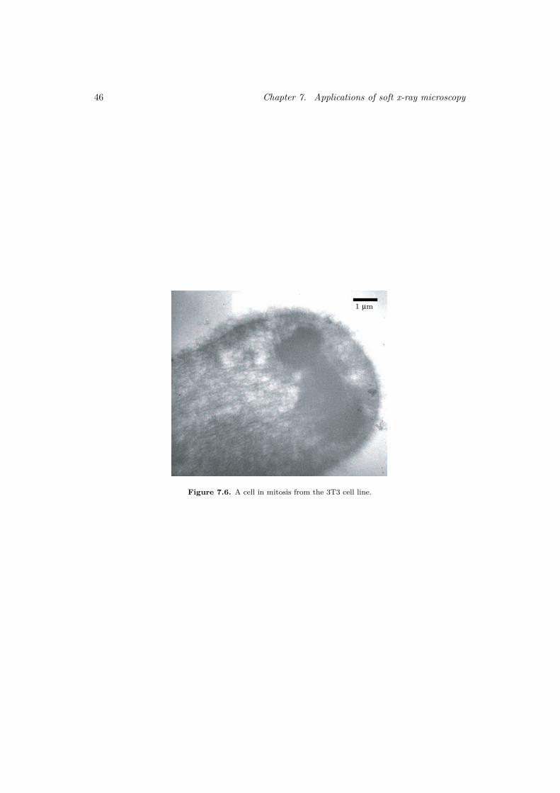
46 Chapter 7. Applications of soft x-ray microscopy
1 µm
Figure 7.6. A cell in mitosis from the 3T3 cell line.

Chapter 8
Summary of the papers
This thesis is based on the following seven papers which are all directed toward the devel-opment of a compact soft x-ray microscope.
Paper 1 presents the design and implementation of a compact soft x-ray reflectometer.The purpose of this instrument was to be able to measure multilayer period and absolutereflectivity with high accuracy on water-window multilayer mirrors. This work was a partof the effort to develop new and more efficient condenser mirrors for the compact soft x-raymicroscope.
Paper 2 describes a method using more than one reflection maximum in the angularreflectivity spectra to improve the accuracy of multilayer period measurements.
Paper 3 introduces a method to enhance the soft x-ray reflectivity of Cr/Sc multilayermirrors using ion assisted magnetron sputtering deposition. Furthermore, different charac-terization methods for multilayers are discussed and some recent results on absolute reflec-tivity measurements are presented.
Paper 4 presents a new and user-friendly design of a compact soft x-ray microscope. Theinstrument is mechanically and thermally stable and is designed for long exposure timeswithout loss of image quality and full-day operation.
Paper 5 reports on the latest progress on the development on Cr/Sc multilayers.
Paper 6 describes an experiment to evaluate the use of soft x-ray microscopy to imagesensory cells. The experiment was performed with the soft x-ray microscope at LawrenceBerkeley National Laboratory (LBNL).
Paper 7 presents a new and improved concept for capillary nozzles for liquid-jet laser-plasma x-ray sources.
The work in this thesis can be divided into three parts. The first work was concentratedon the characterization of multilayer optics and resulted in papers 1, 2, 3, and 5. Theauthor has been the main responsible for papers 1 and 2. He has done the design andimplementation of the compact soft x-ray reflectometer. The author is also responsiblefor the absolute reflectivity calibration of the instrument and has done almost all soft x-ray
47

48 Chapter 8. Summary of the papers
measurements on multilayer samples developed and manufactured by the Thin Film Physicsgroup at Linkoping University.
The author was not involved in the simulation, materials selection, and fabrication ofmultilayer mirrors. The author has been involved in characterization of multilayer sampleon-site at both the Advance Light Source, Berkeley and BESSY, Berlin.
The second part concerns work on a new design of the compact soft x-ray microscopeand is described in paper 4 and 7. The author has together with Dr. Magnus Berglunddesigned and implemented a completely new experimental arrangement for a compact softx-ray microscope. This work is described in paper 4. After an idea from the author, theconcept capillary nozzles for liquid-jet was developed [Paper 7].
Finally, paper 6 describes one of the projects that the author was involved in, during hisfive months stay at the Centre for X-Ray Optics, Lawrence Berkeley National Laboratory.The author performed the x-ray microscopy part of this project.
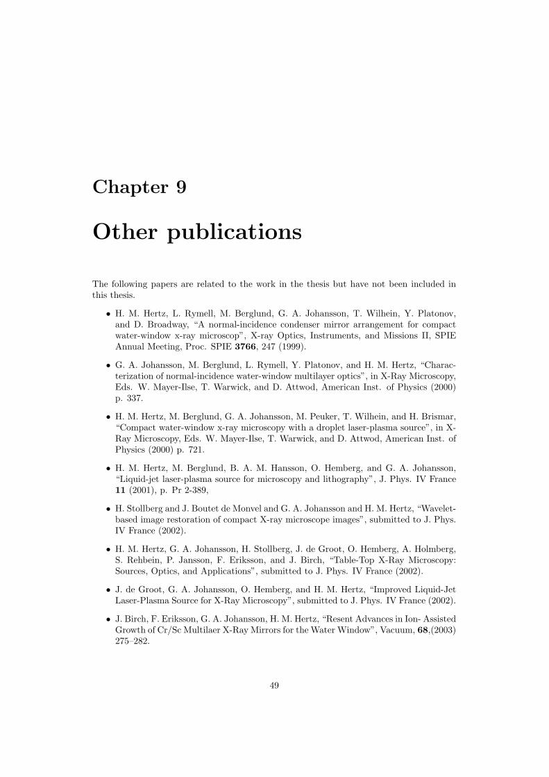
Chapter 9
Other publications
The following papers are related to the work in the thesis but have not been included inthis thesis.
• H. M. Hertz, L. Rymell, M. Berglund, G. A. Johansson, T. Wilhein, Y. Platonov,and D. Broadway, “A normal-incidence condenser mirror arrangement for compactwater-window x-ray microscop”, X-ray Optics, Instruments, and Missions II, SPIEAnnual Meeting, Proc. SPIE 3766, 247 (1999).
• G. A. Johansson, M. Berglund, L. Rymell, Y. Platonov, and H. M. Hertz, “Charac-terization of normal-incidence water-window multilayer optics”, in X-Ray Microscopy,Eds. W. Mayer-Ilse, T. Warwick, and D. Attwod, American Inst. of Physics (2000)p. 337.
• H. M. Hertz, M. Berglund, G. A. Johansson, M. Peuker, T. Wilhein, and H. Brismar,“Compact water-window x-ray microscopy with a droplet laser-plasma source”, in X-Ray Microscopy, Eds. W. Mayer-Ilse, T. Warwick, and D. Attwod, American Inst. ofPhysics (2000) p. 721.
• H. M. Hertz, M. Berglund, B. A. M. Hansson, O. Hemberg, and G. A. Johansson,“Liquid-jet laser-plasma source for microscopy and lithography”, J. Phys. IV France11 (2001), p. Pr 2-389,
• H. Stollberg and J. Boutet de Monvel and G. A. Johansson and H. M. Hertz, “Wavelet-based image restoration of compact X-ray microscope images”, submitted to J. Phys.IV France (2002).
• H. M. Hertz, G. A. Johansson, H. Stollberg, J. de Groot, O. Hemberg, A. Holmberg,S. Rehbein, P. Jansson, F. Eriksson, and J. Birch, “Table-Top X-Ray Microscopy:Sources, Optics, and Applications”, submitted to J. Phys. IV France (2002).
• J. de Groot, G. A. Johansson, O. Hemberg, and H. M. Hertz, “Improved Liquid-JetLaser-Plasma Source for X-Ray Microscopy”, submitted to J. Phys. IV France (2002).
• J. Birch, F. Eriksson, G. A. Johansson, H. M. Hertz, “Resent Advances in Ion- AssistedGrowth of Cr/Sc Multilaer X-Ray Mirrors for the Water Window”, Vacuum, 68,(2003)275–282.
49


Acknowledgments
Finally, I would like to express my gratitude to a number of people upon whom I have reliedduring my graduate studies and for my personal development:
First, to my supervisor Hans Hertz for his guidance, enthusiasm, and encouragement duringmy studies and work. His door is always open and there is always time for discussions.
Magnus Berglund, who introduced me to the world of x-ray microscopy and with whom Ihave had many interesting discussions on any subject.
Bjorn Hansson, Martin Wiklund, Oscar Hemberg, Anders Holmberg, Jaco de Groot, HeideStollberg, Mikael Otendal, Per Jansson, and Stefan Rehbein for successful experiments inthe lab and interesting discussion regarding physics and other essential things in life.
Kjell Carlsson and Anders Liljeborg for their support with optical and electron microscopy.Goran Manneberg and Milan Pokorny for clever optical and mechanical designs.
The rest of my colleagues at the division of Biomedical and X-Ray Physics: Nils Aslund,Klaus Biedermann, Mats Gustafsson, Peter Unsbo, Linda Franzen, and Thomas Koch forfruitful discussions and creating such a stimulating atmosphere.
Fredrik Eriksson, Naureen Ghafoor, and Jens Birch, our collaborators at Linkoping Univer-sity, who makes collaboration so easy. Without their work on multilayers, our compact softx-ray microscopy project would have less bright future.
Rolf Helg and Kjell Hammarstrom from the mechanical workshop at KTH. Without theirwork, none of the experiments described in this thesis would have been possible.
Mats Ulfendahl and Hjalmar Brismar for their help and support on our biologically relatedresearch.
Eric Gullikson for his help on the calibration measurements performed at ALS.
David Attwood, Greg Denbeaux, Erik Anderson, Gerd Schneider, Kathleen Fuller, AngelicPearson, Bill Bates, Weilun Chao, Chang Chang, Kristine Rosfjord, Yanwei Liu, and therest of the team at the Center for X-Ray Optics for their help and unlimited generosityduring my five month visits at Lawrence Berkeley National Laboratory.
To my family and to all my friends, who are the most essential thing in my life.
51


Bibliography
[1] E. Abbe, Schultzes Arc. f. Mikr. Anat. 9, 413 (1873).
[2] E. Abbe, J. R. Microsc. Soc. 4, 348 (1884).
[3] G. Binning, C. F. Quate, and C. Gerber, Phys. Rev. Lett. 56, 930 (1986).
[4] G. Binning, H. Rohrer, C. Gerber, and W. Weibel, Phys. Rev. Lett. 49, 57 (1982).
[5] B. Niemann, D. Rudolph, and G. Schmahl, Appl. Opt. 15, 1883 (1976).
[6] W. C. Rontgen, Sitzungsberichte Med. Phys. Gesellschaft Wurzburg pp. 137–141(1895).
[7] D. Attwood, Soft X-Rays and Extreme Ultraviolet Radiation (Cambridge UniversityPress, New York, 1999).
[8] A. G. Michette and C. J. Buckley, X-Ray Science and Technology (Institute of PhysicsPublishing, Bristol, UK, 1993).
[9] J. A. Samson and D. L. Ederer, eds., Vacuum Ultraviolet Spectroscopy I, vol. 31 ofExperimental Methods in the Physical Sciences (Academic Press, San Diego, 1998).
[10] J. A. Samson and D. L. Ederer, eds., Vacuum Ultraviolet Spectroscopy II, vol. 32 ofExperimental Methods in the Physical Sciences (Academic Press, San Diego, 1998).
[11] S. Webb, ed., The Physics of Medical Imaging, Medical Science Series (Institute ofPhysics Publishing, Bristol, 1988).
[12] http://www-ssrl.slac.stanford.edu/LCLS/.
[13] B. K. Agarwal, X-Ray Spectroscopy, vol. 15 of Springer Series in Optical Sciences
(Springer-Verlag, Berlin, Germany, 1991), 2 ed.
[14] P. G. O’Shea and H. P. Freund, Science 292, 1853 (2001).
[15] K.-J. Kim, Phys. Rev. Lett. 57(15), 1871 (1986).
[16] R. Kauffman, in Physics of Laser Plasma, edited by A. Rubenchik and S. Witkowski(North-Holland, Amsterdam, 1991), vol. 3 of Handbook of Plasma Physics, chap. 3,pp. 111–162.
[17] D. Attwood, chap. 6, in [7].
[18] L. Rymell, M. Berglund, and H. M. Hertz, Appl. Phys. Lett. 66, 2625 (1995).
53

54 BIBLIOGRAPHY
[19] M. Berglund, A Compact Soft X-ray Microscope Based on a Laser-Plasma Source,Ph.D. thesis, Royal Institute of Technology (KTH), Stockholm, Sweden (1999).
[20] J. A. Trail, A Compact Scanning Soft X-Ray Microscope, Ph.D. thesis, Stanford Uni-versity (1989).
[21] C. E. Max, in Physics of the Coronal Plasma in Laser Fusion Targets (LawrenceLivermore National Laboratory, Livermore, California, 1982), vol. I of Physics of
Laser Fusion.
[22] D. V. Korobkin, C. H. Nam, and S. Suckewer, Phys. Rev. Lett. 77(26), 5206 (1996).
[23] H. Daido, S. Sebban, N. Sakaya, Y. Tohyama, T. Norimatsu, K. Mima, Y. Kato,S. Wang, Y. Gu, G. Huang, H. Tang, K. Murai, et al., J. Opt. Soc. Amer. B 16(12),2295 (1999).
[24] B. R. Benware, C. D. Macchietto, C. H. Moreno, and J. J. Rocca, Phys. Rev. Lett.81(26), 5804 (1998).
[25] T. N. Lee, S. H. Kim, and H. J. Shin (1997), vol. 3156 of Proc. SPIE, pp. 250–259.
[26] H. Daido, Rep. Prog. Phys. 65, 1513 (2002).
[27] D. Attwood, chap. 7, in [7].
[28] A. Rundquist, C. G. Durfee III, Z. Chang, C. Herne, S. Backus, M. M. Murnane, andH. C. Kapteyn, Science 280, 1412 (1998).
[29] M. Wieland, R. Frueke, T. Wilhein, C. Spielmann, M. Pohl, and U. Kleineberg, Appl.Phys. Lett. 81(14), 2520 (2002).
[30] E. Spiller, Soft X-Ray Optics (SPIE Optical Engineering Press, Bellingham, Wash-ington, 1994).
[31] A. G. Michette, Optical Systems for Soft X-Rays (Plenum Press, New York, 1986).
[32] B. Cederstrom, A Multi-Prism Lens for Hard X-Rays, Ph.D. thesis, Royal Instituteof Technology (KTH) (2002).
[33] E. Hecht, Optics (Addison-Wesley, Reading, Massachusetts, 1987).
[34] G. Schneider, High-Resolution X-Ray Microscopy of Radiation Sensitive Material
(Cuvillier Verlag, Gttingen, Germany, 1999).
[35] G. Schmahl, D. Rudolph, G. Schneider, J. Thieme, T. Schliebe, B. Kaulich, andM. Hettwer, Microelectrics Engineering 32, 352 (1996).
[36] V. V. Aristov and A. I. Erko, eds., X-Ray Microscopy IV (Bogorodskii Pechatnik,Moscow, Russia, 19934).
[37] E. H. Anderson, D. L. Olynick, B. Harteneck, E. Veklerov, G. Denbeaux, W. Chao,A. Lucero, L. Johnson, and D. Attwood, J. Vac. Sci. Technol. B 18(6), 2970 (2000).
[38] S. J. Spector, C. J. Jacobsen, and D. M. Tennant, J. Vac. Sci. Technol. B 15, 2872(1997).

BIBLIOGRAPHY 55
[39] T. Wilhein, S. Rehbein, D. Hambach, M. Berglund, L. Rymell, and H. M. Hertz, Rev.Sci. Inst. 70, 1694 (1999).
[40] J. Kirz, J. Opt. Soc. America 64(3), 301 (1974).
[41] M. Peuker, Appl. Phys. Lett. 78(15), 2208 (2001).
[42] J. Thieme, G. Schmahl, D. Rudolph, and E. Umbach, eds., X-Ray Microscopy and
Spectromicroscopy (Springer, Heidelberg, 1998).
[43] W. Meyer-Ilse, T. Warwick, and D. Attwood, eds., X-Ray Microscopy, vol. 507 of AIPConference Proceedings (AIP Conference Proceedings, New York, USA, 2000).
[44] A. Snigirev, V. Kohn, I. Snigireva, and B. Lengeler, Nature 384, 49 (1996).
[45] B. Cederstrom, R. Cahn, M. Danielsson, M. Lundquist, and D. Nygren, Nature 404,951 (2000).
[46] B. Henke, E. Gullikson, and J. Davis, X-ray interactions: photoabsorption, scattering,
transmission, and reflection at E=50-30000 eV, Z=1-92, Atomic Data and Nuclear
Data Tables (1993).
[47] http://www.cxro.lbl.gov/optical constants/.
[48] P. Kirkpatrick and A. V. Baez, J. Opt. Soc. Amer. 38, 766 (1948).
[49] P. Kirkpatrick, Sci. Am. 180, 44 (1949).
[50] C. Montcalm et al. (1998), vol. 3331 of Proc. SPIE.
[51] G. Gutman, J. X-Ray Sci. Technol. 4, 142 (1994).
[52] D. Attwood, chap. 4, p. 112, in [7].
[53] N. N. Salashenko and E. A. Shamov, Opt. Commun. 134, 7 (1997).
[54] N. N. Salashenko, A. A. Fraerman, S. V. Mitenin, K. A. Prokhorov, and E. A. Shamov,Nucl. Instrum. Meth. A 405, 292 (1998).
[55] F. Schafers, H.-C. Mertins, F. Schmolla, I. Packe, N. N. Salashenko, and E. A. Shamov,Appl. Opt. 37(4), 719 (1998).
[56] F. Schafers, M. Mertin, D. Abramsohn, A. Gaupp, H.-C. Mertins, and N. N.Salashenko, Nucl. Inst. & Meth. in Phys. Res. A 467–468, 349 (2001).
[57] J. Birch, F. Eriksson, G. A. Johansson, and H. M. Hertz, Vacuum 68, 275 (2003).
[58] A. G. Michette and C. J. Buckley, chap. 7, p. 285, in [8].
[59] F. Eriksson, Multilayer X-ray Mirrors for Water Window Wavelengths, Licentiatethesis, Linkoping University (2001).
[60] H.-C. Mertins, F. Schafers, H. Grimmer, D. Clemens, P. Boni, and M. Horisberger,Appl. Opt. 37(10), 1873 (1998).
[61] D. Windt, Computers in Physics 12, 360 (1998).
[62] http://www.cxro.lbl.gov.

56 BIBLIOGRAPHY
[63] B. D. Cullity, Elements of x-ray diffraction (Prentice-Hall, Inc., New Jersey,1978,2001), 3 ed.
[64] J. H. Underwood, E. M. Gullikson, M. Koike, P. J. Batson, P. E. Denham, K. D.Franck, R. Tackaberry, and W. F. Steele, Rev. Sci. Inst. 67, 5 (1996).
[65] D. Fuchs, M. Krumrey, P. Muller, F. Scholze, and G. Ulm, Rev. Sci. Inst. 66, 2248(1995).
[66] F. Schafers, H.-C. Mertins, A. Gaupp, W. Gudat, M. Mertin, I. Packe, F. Schmolla,S. Di Fonzo, G. Soullie, W. Jark, R. Walker, X. Le Cann, et al., Appl. Opt. 38(19),4074 (1999).
[67] E. M. Gullikson, S. Mrowka, and B. B. Kaufmann (2001), vol. 4144 of Proc. SPIE.
[68] M. R. Weiss, R. Follath, K. J. S. Sawhney, F. Senf, J. Bahrdt, W. Frentrup, A. Gaupp,S. Sasaki, M. Scheer, H. C. Mertins, D. Abramsohn, F. Schafers, et al., Nucl. Inst. &Meth. in Phys. Res. A 467-468, 449 (2001).
[69] F. Eriksson, N. Ghafoor, J. Birch, G. A. Johansson, F. Schafers, H.-C. Mertins, andD. Abramsohn, in BESSY Annual Report (http://www.bessy.de/publications/, 2002).
[70] J. A. Trail, R. L. Byer, and T. W. Barbee, Jr., Appl. Phys. Lett. 52, 269 (1988).
[71] S. Nakayama, M. Yanagihara, M. Yamamoto, H. Kimura, and T. Namioka, Phys.Scripta 41, 754 (1990).
[72] E. M. Gullikson, J. H. Underwood, P. C. Batson, and V. Nikitin, J. X-Ray Sci.Technol. 3, 283 (1992).
[73] D. L. Windt and W. K. Waskiewicz, in Multilayer Optics for Advanced X-Ray Appli-
cations (1992), vol. 1547 of Proc. SPIE, pp. 144–158.
[74] L. Malmqvist, L. Rymell, M. Berglund, and H. M. Hertz, Rev. Sci. Inst. 67, 4150(1996).
[75] L. Rymell and H. M. Hertz, Opt. Commun. 103, 105 (1993).
[76] H. Wolter, Ann. Physik 10(94) (1952).
[77] C. Jacobsen, J. Kirz, and S. Williams, Ultramicroscopy 47, 55 (1992).
[78] G. Denbeaux, E. Anderson, W. Chao, T. Eimuller, L. Johnson, M. Khler, C. Larabell,M. Le Gros, P. Fischer, A. Pearson, G. Schutz, D. Yager, et al., Nucl. Inst. & Meth.in Phys. Res. A 467–468, 841 (2001).
[79] D. Attwood, Soft X-Rays and Extreme Ultraviolet Radiation, chap. 9, p. 371, in [7](1999).
[80] D. Sayre, J. Kirz, R. Feder, D. M. Kim, and E. Spiller, Science 196, 1339 (1977).
[81] J. Kirz, C. Jacobsen, and M. Howells, Q. Rev. Biophys 28(1), 33 (1995).
[82] C. Jacobsen, Trends in Cell Biology 9, 44 (1999).
[83] R. D. Allen, G. B. David, and G. Nomarski, Z. wiss. Mikr. 69, 193 (1969).

BIBLIOGRAPHY 57
[84] G. Schmahl and D. Rudolph, in X-Ray Microscopy Instrumentation and Biological
Applications, edited by P. C. Cheng and G. J. Jan (Springer, Berlin, 1987).
[85] T. Wilhein, B. Kaulich, and J. Susini, Opt. Commun. 193, 19 (2001).
[86] B. Niemann, G. Schneider, P. Guttmann, D. Rudolph, and G. Schmahl, in Aristovand Erko [36], pp. 66–75.
[87] U. Neuhausler, C. Jacobsen, D. Schulze, D. Stott, and S. Abend, J. Synchrotron Rad.7, 110 (2000).
[88] G. Schneider, Ultramicroscopy 75, 85 (1998).
[89] W. Meyer-Ilse, D. Hamamoto, A. Nair, S. A. Lelievre, G. Denbeaux, L. Johnson, A. L.Pearson, D. Yager, M. A. Legros, and C. A. Larabell, J. Microscopy 201, 395 (2001).
[90] H. N. Chapman, C. Jacobsen, and S. Williams, Ultramicroscopy 62, 191 (1996).
[91] K. Shinohara and A. Ito, J. Microscopy 161, 463 (1991).
[92] S. Williams, X. Zhang, C. Jacobsen, J. Kirz, S. Lindaas, J. Van’t Hof, and S. S.Lamm, J. Microscopy 170(2), 155 (1993).
[93] B. Niemann, D. Rudolph, and G. Schmahl, Opt. Commun. 12, 160 (1974).
[94] G. Schmahl, D. Rudolph, B. Niemann, P. Guttmann, J. Thieme, G. Schneider,C. David, M. Diehl, and T. Wilhein, Optik 93(3), 95 (1993).
[95] P. Guttmann, B. Niemann, J. Thieme, D. Hambach, G. Schneider, U. Wiesemann,D. Rudolph, and G. Schmahl, Nucl. Inst. & Meth. in Phys. Res. A 467–468, 849(2001).
[96] W. Meyer-Ilse, H. Medecki, L. Jochum, E. Anderson, D. Attwood, C. Magowan,R. Balhorn, M. Moronne, D. Rudolph, and S. G., Synchrotron Radiation News 8(3),29 (1995).
[97] W. Meyer-Ilse, G. Denbeaux, L. Johnson, W. Bates, A. Lucero, and E. Anderson, inMeyer-Ilse et al. [43], pp. 129–134.
[98] http://www.als.lbl.gov/als/als users bl/6.1.2-Datasheet.pdf.
[99] C. Jacobsen, S. Williams, E. Anderson, M. T. Browne, C. J. Buckley, D. Kern, J. Kirz,M. Rivers, and X. Zhand, Opt. Commun. 86, 351 (1991).
[100] J. Maser, A. Osanna, Y. Wang, C. Jacobsen, J. Kirz, S. Spector, B. Winn, andD. Tennant, J. Microscopy 197(1), 68 (2000).
[101] X. Zhang, H. Ade, C. Jacobsen, J. Kirz, S. Lindaas, S. Williams, and S. Wirick, Nucl.Inst. & Meth. in Phys. Res. A 347, 431 (1994).
[102] J. Susini, R. Barret, B. Kaulich, S. Oestreich, and Salome, in Meyer-Ilse et al. [43],pp. 19–26.
[103] I. McNulty, S. P. Frigo, C. C. Retsch, Y. Wang, Y. P. Feng, Y. Qian, E. Trakhtenberg,B. Tieman, B.-C. Cha, K. Goetze, T. Mooney, and W. S. Haddad (1998), vol. 3449of Proc. SPIE, pp. 67–74.
58 BIBLIOGRAPHY
[104] A. Takeuchi, H. Takano, K. Uesugi, and Y. Suzuki (2001), vol. 4499 of Proc. SPIE,pp. 29–37.
[105] Y. Wang and C. Jacobsen, J. Microscopy 191(2), 159 (1997).
[106] J. M. Rajyaguru, M. Kado, D. Torres, M. Richardson, and J. Muszynski, J. Mi-croscopy 188(2), 96 (1997).
[107] I. McNulty, J. Kirz, C. Jacobsen, E. H. Anderson, M. R. Howells, and D. P. Kern,Science 256(5059), 1009 (1992).
[108] M. Berglund, L. Rymell, M. Peuker, T. Wilhein, and H. M. Hertz, J. Microscopy 197,268 (2000).
[109] M. Berglund, A Compact Soft X-ray Microscope Based on a Laser-Plasma Source,Ph.D. thesis, Royal Inst. of Tech. (KTH), Stockholm (1999).
[110] O. Hemberg, B. A. M. Hansson, M. Berglund, and H. M. Hertz, J. Appl. Phys. 88(9),5421 (2000).
[111] J. de Groot, O. Hemberg, A. Holmberg, and H. M. Hertz, manuscript in preparationfor J. Appl. Phys.
[112] L. Rymell and H. M. Hertz, Opt. Commun. 103, 105 (1993).
[113] L. Malmqvist, L. Rymell, M. Berglund, and H. M. Hertz, Rev. Sci. Inst. 67, 4150(1996).
[114] L. Rymell and H. M. Hertz, Rev. Sci. Inst. 66, 4916 (1995).
[115] M. Berglund, L. Rymell, and H. M. Hertz, Appl. Phys. Lett. 69, 1683 (1996).
[116] P. Jansson, Stable Liquid-Nitrogen-Jet Target for Laser-Plasma X-Ray Generation,Master’s thesis, Royal Institute of Technology (KTH), Stockholm, Sweden (2002).
[117] T. Wilhein, D. Hambach, B. Niemann, M. Berglund, L. Rymell, and H. M. Hertz,Appl. Phys. Lett. 71, 190 (1997).
[118] H. M. Hertz, L. Rymell, M. Berglund, G. A. Johansson, T. Wilhein, Y. Platonov,and D. Broadway, in X-Ray Optics, Instruments, and Missions II (1999), vol. 3766of Proc. SPIE, pp. 247–251.
[119] Gerd Schneider and Stefan Rehbein, personal communication.
[120] Anders Homberg, personal communication.
[121] T. Wilhein, Gedunnte CCDs: Charakterisierung und anwendungen im bereich weicher
rontgenstrahlung, Ph.D. thesis, University of Gottingen (1994).
[122] Heide Stollberg, personal communication.
[123] H. Stollberg, J. Boutet de Monvel, G. A. Johansson, and H. M. Hertz, submitted toJ. Phys. IV France (2002).
[124] M. Berglund, L. Rymell, H. M. Hertz, and T. Wilhein, Rev. Sci. Inst. 69, 2361 (1998).
[125] G. Schmahl, D. Rudolph, B. Niemann, and O. Christ, Q. Rev. Biophys 13, 297 (1980).

BIBLIOGRAPHY 59
[126] P. Fischer, G. Denbeaux, T. Ono, T. Okuno, T. Eimuller, D. Goll, and G. Schutz, J.Phys. D: Appl. Phys. 35, 2391 (2002).
[127] G. Schneider, G. Denbeaux, E. Anderson, W. Bates, F. Salmassi, P. Nachimuthu,A. Pearson, D. Richardson, D. Hambach, N. Hoffmann, W. Hasse, and K. Hoffmann,Nucl. Inst. & Meth. in Phys. Res. B 199, 469 (2003).
[128] X. Zhang, C. Jacobsen, S. Lindaas, and S. Williams, J. Vac. Sci. Technol. B 13, 1477(1995).
[129] S. G. Urquhart, A. P. Hitchcock, A. P. Smith, H. W. Ade, W. Lidy, E. G. Rightor,and G. E. Mitchell, J. Electr. Spectros. Relat. Phenom. 100, 119 (1999).
[130] J. Thieme and J. Niemeyer, Progr Colloid Polym Sci 111, 193 (1998).
[131] C. Schmidt, J. Thieme, U. Neuhausler, U. Schulte-Ebbert, G. Abbt-Braun, C. Specht,and C. Jacobsen, in Meyer-Ilse et al. [43], pp. 313–318.
