compact plastic limit switches with positive opening ...us.azbil.com/uploadedspecs/qqhgiljk.pdf1...
TRANSCRIPT

1
LJK-NSeries
CATALOG LISTING
Positive opening mechanism meets standards worldwide. A wide variety of actuators is available.
Compact plastic limit switches with positive opening mechanism
The LJK-N conforms to IEC standards, and is certified by UL and CSA. For equipment and facilities to be exported anywhere in the world, use the LJK-N with confidence.
Positive opening mechanism forces contacts open.* •Can prevent problems caused by contact fusing.
•Can be used also as a safety limit switch.
Wide variety, with 33 catalog listings in the lineup •Actuators: 11 types
•Contact configuration Snap action: N.C. x 1 + N.O. x 1 Slow action: N.C. x + N.O. x 1 (BBM: break before make), N.C. x 2
*Except for the steel wire and spring rod types.
Internal switch mechanismType of actuator Contact configuration Catalog listing
Snap actionSlow action BBM
Slow actionSnap action
Slow action BBMSlow actionSnap action
Slow action BBMSlow actionSnap action
Slow action BBMSlow actionSnap action
Slow action BBMSlow actionSnap action
Slow action BBMSlow actionSnap action
Slow action BBMSlow actionSnap action
Slow action BBMSlow actionSnap action
Slow action BBMSlow actionSnap action
Slow action BBMSlow actionSnap action
Slow action BBMSlow action
N.C. x 1 + N.O. x 1N.C. x 1 + N.O. x 1
N.C. x 2N.C. x 1 + N.O. x 1N.C. x 1 + N.O. x 1
N.C. x 2N.C. x 1 + N.O. x 1N.C. x 1 + N.O. x 1
N.C. x 2N.C. x 1 + N.O. x 1N.C. x 1 + N.O. x 1
N.C. x 2N.C. x 1 + N.O. x 1N.C. x 1 + N.O. x 1
N.C. x 2N.C. x 1 + N.O. x 1N.C. x 1 + N.O. x 1
N.C. x 2N.C. x 1 + N.O. x 1N.C. x 1 + N.O. x 1
N.C. x 2N.C. x 1 + N.O. x 1N.C. x 1 + N.O. x 1
N.C. x 2N.C. x 1 + N.O. x 1N.C. x 1 + N.O. x 1
N.C. x 2N.C. x 1 + N.O. x 1N.C. x 1 + N.O. x 1
N.C. x 2N.C. x 1 + N.O. x 1N.C. x 1 + N.O. x 1
N.C. x 2
LJK-N2118F12LJK-N2518F12LJK-N2718F12LJK-N2145F12LJK-N2545F12LJK-N2745F12LJK-N2139F12LJK-N2539F12LJK-N2739F12LJK-N2149F12LJK-N2549F12LJK-N2749F12LJK-N2110F12LJK-N2510F12LJK-N2710F12LJK-N2102F12LJK-N2502F12LJK-N2702F12LJK-N2103F12LJK-N2503F12LJK-N2703F12LJK-N2121F12LJK-N2521F12LJK-N2721F12LJK-N2127F12LJK-N2527F12LJK-N2727F12LJK-N2106F12LJK-N2506F12LJK-N2706F12LJK-N2108F12LJK-N2508F12LJK-N2708F12
Resin roller lever
Resin adjustable roller lever
50mm dia. resin roller lever
50mm dia. resin adjustable roller lever
Plunger
Resin roller plunger
Resin cross roller plunger
Resin one-way roller (horizontal)
Resin one-way roller (vertical)
Steel wire
Spring rod
Positive opening mechanism
2
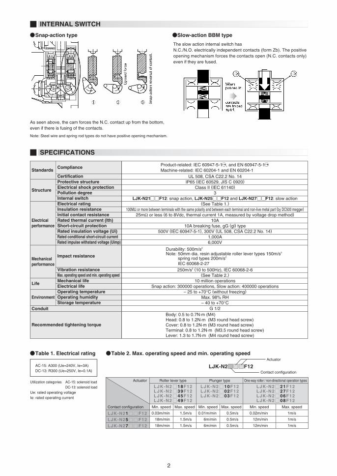
INTERNAL SWITCH
SPECIFICATIONS
AC-15: A300 (Ue=240V, Ie=3A)DC-13: R300 (Ue=250V, Ie=0.1A)
Utilization categories AC-15: solenoid load DC-13: solenoid loadUe: rated operating voltageIe: rated operating current
StandardsCompliance
CertificationProtective structureElectrical shock protectionPollution degree
Electricalperformance
Internal switchElectrical ratingInsulation resistanceInitial contact resistanceRated thermal current (Ith)Short-circuit protectionRated insulation voltage (Ui)Rated conditional short-circuit currentRated impulse withstand voltage (Uimp)
Mechanicalperformance
Impact resistance
Vibration resistanceMax. operating speed and min. operating speedMechanical lifeElectrical life
EnvironmentOperating temperatureOperating humidityStorage temperature
Recommended tightening torque
Structure
Life
Conduit
UL 508, CSA C22.2 No. 14IP65 (IEC 60529, JIS C 0920)
Class II (IEC 61140)3
LJK-N21 F12: snap action, LJK-N25 F12 and LJK-N27 F12: slow action(See Table 1.)
100MΩ or more between terminals with the same polarity and between each terminal and non-live metal part (by DC500 megger)25mΩ or less (6 to 8Vdc, thermal current 1A, measured by voltage drop method)
10A10A breaking fuse, gG (gl) type
500V (IEC 60947-5-1), 300V (UL 508, CSA C22.2 No. 14)1,000A6,000V
250m/s2 (10 to 500Hz), IEC 60068-2-6(See Table 2.)
10 million operationsSnap action: 300000 operations, Slow action: 400000 operations
– 25 to +70°C (without freezing)Max. 98% RH– 40 to +70°C
Durability: 500m/s2 Note: 50mm dia. resin adjustable roller lever types 150m/s2
spring rod types 200m/s2
IEC 60068-2-27
Body: 0.5 to 0.7N·m (M4)Head: 0.8 to 1.2N·m (M3 round head screw)Cover: 0.8 to 1.2N·m (M3 round head screw)Terminal: 0.8 to 1.2N·m (M3.5 round head screw) Lever: 1.3 to 1.7N·m (M4 round head screw)
G 1/2
LJK-N21 F12LJK-N25 F12LJK-N27 F12
Min. speedContact configuration
Contact configuration
Max. speed Min. speed Max. speed Min. speed Max. speed
Roller lever type Plunger type One-way roller / non-directional operation types
LJK-N2 18F12LJK-N2 39F12LJK-N2 45F12LJK-N2 49F12
Actuator
Actuator
LJK-N2 10F12LJK-N2 02F12LJK-N2 03F12
LJK-N2 21F12LJK-N2 27F12LJK-N2 06F12LJK-N2 08F12
0.03m/min
18m/min
18m/min
1.5m/s
1.5m/s
1.5m/s
0.01m/min
6m/min
6m/min
0.5m/s
0.5m/s
0.5m/s
0.02m/min
12m/min
12m/min
1m/s
1m/s
1m/s
As seen above, the cam forces the N.C. contact up from the bottom, even if there is fusing of the contacts.
Note: Steel wire and spring rod types do not have positive opening mechanism.
The slow action internal switch hasN.C./N.O. electrically independent contacts (form Zb). The positive opening mechanism forces the contacts open (N.C. contacts only) even if they are fused.
Snap-action type
Table 1. Electrical rating Table 2. Max. operating speed and min. operating speed
Slow-action BBM type
Product-related: IEC 60947-5-1 , and EN 60947-5-1 Machine-related: IEC 60204-1 and EN 60204-1
3
Free position
TT
POPT2
PT1
MD MD
PT1
PT2
PO
TT TT
PO
PT
2
PT
1
MD
MD
PT2PT1
MD
PT2
PT1
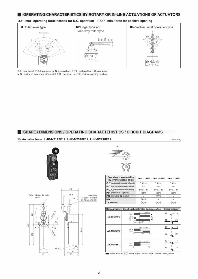
•Roller lever type •Plunger type and one-way roller type
•Non-directional operation type
O.F.: max. operating force needed for N.C. operation P.O.F: min. force for positive opening
T.T.: total travel. P.T.1: pretravel for N.C. operation. P.T.2: pretravel for N.O. operation.M.D.: minimum movement differential. P.O.: minimum travel to positive opening position.
Resin roller lever: LJK-N2118F12, LJK-N2518F12, LJK-N2718F12
Catalog listing Operating characteristics by dog operation Circuit diagram
LJK-N2118F12
LJK-N2518F12
LJK-N2718F12
Operating characteristics by lever rotational angle
O.F. (max. operating force needed for N.C. operation)
P.O. (min. travel to positive opening position)
P.O.F. (minimum force for positive opening)
PT1 (pretravel for N.C. operation)
PT2 (pretravel for N.O. operation)
MDTT (total travel)
LJK-N2118F12
0.1N·m
50°0.15N·m
(25°)–
(16°)(70°)
LJK-N2518F12
0.1N·m
47°0.15N·m
(28°)(38°)
–(70°)
LJK-N2718F12
0.1N·m
41°0.15N·m
(27°)–
–(70°)
30°
Roller: 19 dia. x 5.5 width, plastic
: Contacts closed : Contacts open (P): Min. travel to positive opening position
Roller lever can also be mounted on the opposite side.
39.8
24
2515
30
30
22
20
53.6 26
54.5
81.6
R2.
15 ( 2
)
R2.15 (2 )
2
18.1
6
(2)
( 108
.1)
G 1/2
37
44.5
1421-2213-1421-2213-14
0° 70°
50°(P)25°
16°
13
22 21
14 13
22 21
21-2213-14
0° 70°
47°(P)28°
38°
11-1221-22
0° 70°
41°(P)27° 12 11
22 21
(unit: mm)
OPERATING CHARACTERISTICS BY ROTARY OR IN-LINE ACTUATIONS OF ACTUATORS
SHAPE / DIMENSIONS / OPERATING CHARACTERISTICS / CIRCUIT DIAGRAMS

4
50mm dia. resin roller lever: LJK-N2139F12, LJK-N2539F12, LJK-N2739F12
R26 to 75
38.1
29.1
20 25
42.3
30
39.7
G 1/222
30
( 108
to 1
57) ( 5
3.5
to 1
02.5
)
( 35.
5 to
84.
5)
R2.15
( 2)
R2.15 (2 )
2 (2)
30°
30°
49.5
25
15
20
22
30
30
G 1/2
37
42
20
3378
(12
6) R2.
15 ( 2
)
R2.15 (2 )
2 (2)
81.6
15
81.6
Roller lever can also be mounted on the opposite side.
Roller lever can also be mounted on the opposite side.
Catalog listing Operating characteristics by dog operation Circuit diagram
LJK-N2139F12
LJK-N2539F12
LJK-N2739F12
Operating characteristics by lever rotational angle
O.F. (max. operating force needed for N.C. operation)
P.O. (min. travel to positive opening position)
P.O.F. (minimum force for positive opening)
PT1 (pretravel for N.C. operation)
PT2 (pretravel for N.O. operation)
MDTT (total travel)
LJK-N2139F12
0.1N·m
50°0.15N·m
(25°)–
(16°)(70°)
LJK-N2539F12
0.1N·m
47°0.15N·m
(28°)(38°)
–(70°)
LJK-N2739F12
0.1N·m
41°0.15N·m
(27°)–
–(70°)
: Contacts closed : Contacts open (P): Min. travel to positive opening position
1421-2213-1421-2213-14
0° 70°
50°(P)25°
16°
13
22 21
14 13
22 21
21-2213-14
0° 70°
47°(P)28°
38°
11-1221-22
0° 70°
41°(P)27° 12 11
22 21
Catalog listing Operating characteristics by dog operation Circuit diagram
LJK-N2145F12
LJK-N2545F12
LJK-N2745F12
Operating characteristics by lever rotational angle
O.F. (max. operating force needed for N.C. operation)
P.O. (min. travel to positive opening position)
P.O.F. (minimum force for positive opening)
PT1 (pretravel for N.C. operation)
PT2 (pretravel for N.O. operation)
MDTT (total travel)
LJK-N2145F12
0.1N·m
50°0.15N·m
(25°)–
(16°)(70°)
LJK-N2545F12
0.1N·m
47°0.15N·m
(28°)(38°)
–(70°)
LJK-N2745F12
0.1N·m
41°0.15N·m
(27°)–
–(70°)
: Contacts closed : Contacts open (P): Min. travel to positive opening position
1421-2213-1421-2213-14
0° 70°
50°(P)25°
16°
13
22 21
14 13
22 21
21-2213-14
0° 70°
47°(P)28°
38°
11-1221-22
0° 70°
41°(P)27° 12 11
22 21
Resin adjustable roller lever: LJK-N2145F12, LJK-N2545F12, LJK-N2745F12 (unit: mm)
Roller: 19 dia. x 5.5 width, plastic
Roller: 50 dia. x 10 width, plastic
5
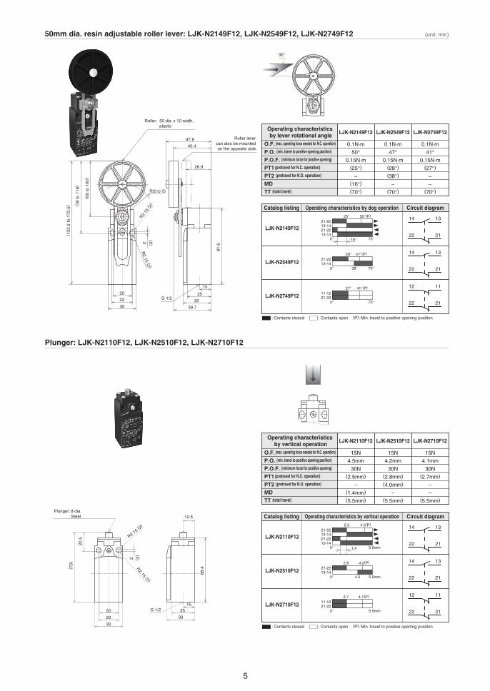
Plunger: LJK-N2110F12, LJK-N2510F12, LJK-N2710F12
50mm dia. resin adjustable roller lever: LJK-N2149F12, LJK-N2549F12, LJK-N2749F12
Roller: 50 dia. x 10 width, plastic
40.4
26.9
20 25
47.9
30
39.7
G 1/222
30
( 78
to 1
18)
( 60
to 1
00)
( 132
.5 to
172
.5)
R2.15
( 2)
R2.15 (2 )
2 ( 2)
30°
Plunger: 8 dia. Steel 12.5
2520
22
30
30
G 1/2
R2.15 (2)
R2.15 (2 )
2
20.5
( 75)
(2)
(unit: mm)
15
81.6
15
68.4
R35 to 75
Roller lever can also be mounted on the opposite side.
Catalog listing Operating characteristics by dog operation Circuit diagram
LJK-N2149F12
LJK-N2549F12
LJK-N2749F12
Operating characteristics by lever rotational angle
O.F. (max. operating force needed for N.C. operation)
P.O. (min. travel to positive opening position)
P.O.F. (minimum force for positive opening)
PT1 (pretravel for N.C. operation)
PT2 (pretravel for N.O. operation)
MDTT (total travel)
LJK-N2149F12
0.1N·m
50°0.15N·m
(25°)–
(16°)(70°)
LJK-N2549F12
0.1N·m
47°0.15N·m
(28°)(38°)
–(70°)
LJK-N2749F12
0.1N·m
41°0.15N·m
(27°)–
–(70°)
: Contacts closed : Contacts open (P): Min. travel to positive opening position
1421-2213-1421-2213-14
0° 70°
50°(P)25°
16°
13
22 21
14 13
22 21
21-2213-14
0° 70°
47°(P)28°
38°
11-1221-22
0° 70°
41°(P)27° 12 11
22 21
Catalog listing Operating characteristics by vertical operation Circuit diagram
LJK-N2110F12
LJK-N2510F12
LJK-N2710F12
Operating characteristics by vertical operation
O.F. (max. operating force needed for N.C. operation)
P.O. (min. travel to positive opening position)
P.O.F. (minimum force for positive opening)
PT1 (pretravel for N.C. operation)
PT2 (pretravel for N.O. operation)
MDTT (total travel)
LJK-N2110F12
15N
4.5mm
30N(2.5mm)
–(1.4mm)
(5.5mm)
LJK-N2510F12
15N
4.2mm
30N(2.8mm)
(4.0mm)
–(5.5mm)
LJK-N2710F12
15N
4.1mm
30N(2.7mm)
–
–(5.5mm)
: Contacts closed : Contacts open (P): Min. travel to positive opening position
1421-2213-1421-2213-14
0° 5.5mm
4.5(P)2.5
1.4
13
22 21
14 13
22 21
21-2213-14
0° 5.5mm
4.2(P)2.8
4.0
11-1221-22
0° 5.5mm
4.1(P)2.7 12 11
22 21
6
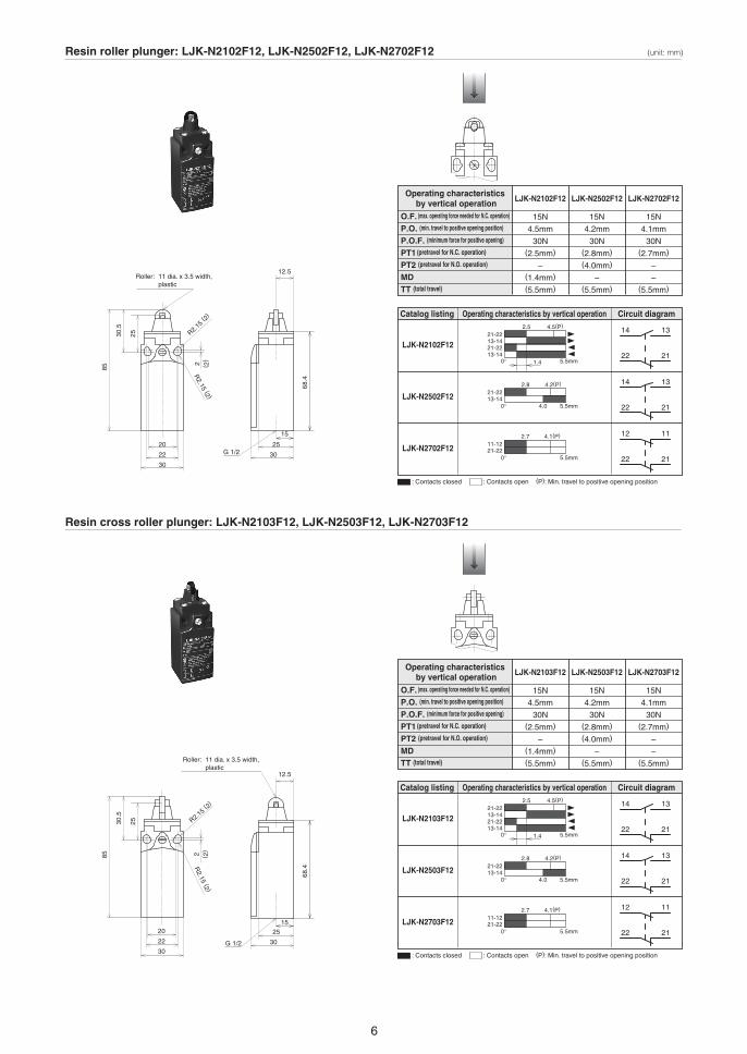
Resin cross roller plunger: LJK-N2103F12, LJK-N2503F12, LJK-N2703F12
Resin roller plunger: LJK-N2102F12, LJK-N2502F12, LJK-N2702F12
Roller: 11 dia. x 3.5 width, plastic
12.5
2520
22
30
30G 1/2
R2.15
( 2)
R2.15 (2 )
2 ( 2)
Roller: 11 dia. x 3.5 width, plastic
12.5
2520
22
3030G 1/2
R2.15 ( 2)
R2.15 (2 )
285
30.5
25
( 2)
(unit: mm)
15
68.4
15
68.4
85
30.5
25
Catalog listing Operating characteristics by vertical operation Circuit diagram
LJK-N2103F12
LJK-N2503F12
LJK-N2703F12
Operating characteristics by vertical operation
O.F. (max. operating force needed for N.C. operation)
P.O. (min. travel to positive opening position)
P.O.F. (minimum force for positive opening)
PT1 (pretravel for N.C. operation)
PT2 (pretravel for N.O. operation)
MDTT (total travel)
LJK-N2103F12
15N
4.5mm
30N(2.5mm)
–(1.4mm)
(5.5mm)
LJK-N2503F12
15N
4.2mm
30N(2.8mm)
(4.0mm)
–(5.5mm)
LJK-N2703F12
15N
4.1mm
30N(2.7mm)
–
–(5.5mm)
: Contacts closed : Contacts open (P): Min. travel to positive opening position
1421-2213-1421-2213-14
0° 5.5mm
4.5(P)2.5
1.4
13
22 21
14 13
22 21
21-2213-14
0° 5.5mm
4.2(P)2.8
4.0
11-1221-22
0° 5.5mm
4.1(P)2.7 12 11
22 21
Catalog listing Operating characteristics by vertical operation Circuit diagram
LJK-N2102F12
LJK-N2502F12
LJK-N2702F12
Operating characteristics by vertical operation
O.F. (max. operating force needed for N.C. operation)
P.O. (min. travel to positive opening position)
P.O.F. (minimum force for positive opening)
PT1 (pretravel for N.C. operation)
PT2 (pretravel for N.O. operation)
MDTT (total travel)
LJK-N2102F12
15N
4.5mm
30N(2.5mm)
–(1.4mm)
(5.5mm)
LJK-N2502F12
15N
4.2mm
30N(2.8mm)
(4.0mm)
–(5.5mm)
LJK-N2702F12
15N
4.1mm
30N(2.7mm)
–
–(5.5mm)
: Contacts closed : Contacts open (P): Min. travel to positive opening position
1421-2213-1421-2213-14
0° 5.5mm
4.5(P)2.5
1.4
13
22 21
14 13
22 21
21-2213-14
0° 5.5mm
4.2(P)2.8
4.0
11-1221-22
0° 5.5mm
4.1(P)2.7 12 11
22 21

1 27
Roller: 14 dia. x 5.5 width, plastic
30°
25
20
22
30 (12.5) 30G 1/2
2
( 95.
5)
( 41)
( 2)
Resin one-way roller (vertical): LJK-N2127F12, LJK-N2527F12, LJK-N2727F12
Resin one-way roller (horizontal): LJK-N2121F12, LJK-N2521F12, LJK-N2721F12
Roller: 14 dia. x 5.5 width, plastic
15
25
20
10
22
30 30
G 1/2
R2.15 ( 2)
R18
R2.15 (2 )
2
( 93.
7)
68.4
( 39.
2)
19
( 2)
13.2
10
R18
1915
30°
(unit: mm)
15
68.4
Catalog listing Operating characteristics by dog operation Circuit diagram
LJK-N2121F12
LJK-N2521F12
LJK-N2721F12
Operating characteristicsby dog operation
O.F. (max. operating force needed for N.C. operation)
P.O. (min. travel to positive opening position)
P.O.F. (minimum force for positive opening)
PT1 (pretravel for N.C. operation)
PT2 (pretravel for N.O. operation)
MDTT (total travel)
LJK-N2121F12
6N
15.9mm
10N(9mm)
–(5.2mm)
–
LJK-N2521F12
6N
14.9mm
10N(10mm)
(14.1mm)
–
–
LJK-N2721F12
6N
14.6mm
10N(9.6mm)
–
–
–
: Contacts closed : Contacts open (P): Min. travel to positive opening position
1421-2213-1421-2213-14
0° 5.2mm
15.9(P)9 13
22 21
14 13
22 21
21-2213-14
0° 14.1mm
14.9(P)10
11-1221-22
0°
14.6(P)9.6 12 11
22 21
Catalog listing Operating characteristics by dog operation Circuit diagram
LJK-N2127F12
LJK-N2527F12
LJK-N2727F12
Operating characteristicsby dog operation
O.F. (max. operating force needed for N.C. operation)
P.O. (min. travel to positive opening position)
P.O.F. (minimum force for positive opening)
PT1 (pretravel for N.C. operation)
PT2 (pretravel for N.O. operation)
MDTT (total travel)
LJK-N2127F12
6N
15.9mm
10N(9mm)
–(5.2mm)
–
LJK-N2527F12
6N
14.9mm
10N(10mm)
(14.1mm)
–
–
LJK-N2727F12
6N
14.6mm
10N(9.6mm)
–
–
–
: Contacts closed : Contacts open (P): Min. travel to positive opening position
1421-2213-1421-2213-14
0° 5.2mm
15.9(P)9 13
22 21
14 13
22 21
21-2213-14
0° 14.1mm
14.9(P)10
11-1221-22
0°
14.6(P)9.6 12 11
22 21
R2.15 (2)
R2.15 (2)
1 28
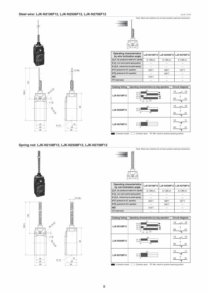
Steel wire: LJK-N2106F12, LJK-N2506F12, LJK-N2706F12Note: Steel wire switches do not have positive opening mechanism.
Note: Steel wire switches do not have positive opening mechanism.
15
1.2 dia.
25
20
22
30 30
G 1/2
R2.15 ( 2)
R2.15 (2 )
2
196.
5
6969
142
( 2)
Spring rod: LJK-N2108F12, LJK-N2508F12, LJK-N2708F12
15
6.4 dia.
25
20
22
30 30
G 1/2
R2.15 ( 2)
R2.15 (2 )
2
182.
5
128
( 2)
(unit: mm)
Catalog listing Operating characteristics by dog operation Circuit diagram
LJK-N2108F12
LJK-N2508F12
LJK-N2708F12
Operating characteristicsby rod inclination angle
O.F. (max. operating force needed for N.C. operation)
P.O. (min. travel to positive opening position)
P.O.F. (minimum force for positive opening)
PT1 (pretravel for N.C. operation)
PT2 (pretravel for N.O. operation)
MDTT (total travel)
LJK-N2108F12
0.13N·m
–
–(25°)
–(15°)
–
LJK-N2508F12
0.13N·m
–
–(28°)(40°)
–
–
LJK-N2708F12
0.13N·m
–
–(27°)
–
–
–
: Contacts closed : Contacts open (P): Min. travel to positive opening position
1421-2213-1421-2213-14
0° 15°
25° 13
22 21
14 13
22 21
21-2213-14
0° 40°
28°
11-1221-22
0°
27° 12 11
22 21
Catalog listing Operating characteristics by dog operation Circuit diagram
LJK-N2106F12
LJK-N2506F12
LJK-N2706F12
Operating characteristics by wire inclination angle
O.F. (max. operating force needed for N.C. operation)
P.O. (min. travel to positive opening position)
P.O.F. (minimum force for positive opening)
PT1 (pretravel for N.C. operation)
PT2 (pretravel for N.O. operation)
MDTT (total travel)
LJK-N2106F12
0.13N·m
–
–(25°)
–(15°)
–
LJK-N2506F12
0.13N·m
–
–(28°)(40°)
–
–
LJK-N2706F12
0.13N·m
–
–(27°)
–
–
–
: Contacts closed : Contacts open (P): Min. travel to positive opening position
1421-2213-1421-2213-14
0° 15°
25° 13
22 21
14 13
22 21
21-2213-14
0° 40°
28°
11-1221-22
0°
27° 12 11
22 21
1 29
HANDLING PRECAUTIONS
1.Mounting the switch
4.Operating environment2.Wiring
3.Adjustment
Always tighten each part of the safety switch to the tightening
torque recommended in the product specifications. If any part is
tightened excessively, the screw and/or other parts may be
damaged.
Mount the dog so that no force is directly applied to the actuator in
the free state.
Do not use any glue or lubricant containing silicone. Doing so
might result in faulty electrical conductivity.
Do not use in a location subject to splashing with strong acid or
alkali.
Do not perform wiring work with the power turned ON. Doing so
might cause an electrical shock or cause the device to operate
suddenly.
Do not apply excessive force (force 5 times larger that the O.F.) to
the actuator when it is beyond the operation limit position. Doing
so might break the switch.
Adjust the actuator motion so that it exceeds the specified P.O.
(travel to positive opening position) but does not exceed the
operation limit position.