compact modular valve assembly modular blocks size 06
TRANSCRIPT

Modular Blocks Size 06 (CETOP 03) with Built-in Valves
P A B T
0,75 (0.03)
5,1 0.20( )15,5 (0.61)
25,9 (1.16)31( )1.22
31,75 (1.25)
TP
B
A
4xM5-6Hx13 (10-24 UNC)
12,7
0.50
()21
,50.8
5(
)30
,21.1
8(
)40
,51.5
9(
)
G
A
B
C
Subject to change · Modular blocks size 06 (CETOP 03) with built-in valves_0057_2en_03/2021
www.argo-hytos.com Page 1
Compact Modular Valve Assembly
› Simple creation of complicated hydraulic circuits › Flexible connection solution › Wide range of valves available › Circuit creation without the use of pipes and hoses › Saves build-in space
Technical Features
Vertically integrated modular blocks with built-in valves are assembled into a single unit using four M5 or 10-24 UNC threaded bolts and mounted to a base, e.g. to a subplate, a parallel circuit manifold with side ports or another block. The connection plate diagram con-forms with ISO 4401. The surface of upper block is usually closed with connected directio-nal control valve with body or with a blanking plate.
Content
Functional Description
pageA. Valves with body on the upper surface (CETOP valves) 2Directional control valves with body 2Proportional directional control valves with body 2Blanking plates 2B. Valves built-in modular blocks 3Directional control valves, spool type 3Poppet valves, direct acting 4Poppet valves, pilot operated 6Check valves 8Check valves, pilot to open 9Load shuttle valves 9Pressure relief valves, direct acting 10Pressure relief valves, pilot operated 11Pressure relief valves operated by solenoid 12Proportional pressure relief valves 12Pressure reducing – relieving valves, direct acting 13Pressure reducing – relieving valves, pilot operated 14Proportional pressure reducing – relieving valves 15Sequence spool valve, hydraulically operated 15Overcenter valves 16Throttle valves with bypass check valve 17Throttle valves 18Flow control valves with 2-way pressure compensator 19Flow control valves with 3-way pressure compensator bypass type 20Pressure compensators 21C. Subplates and manifolds 23Subplates DP 23Parallel circuit manifolds with side ports 23Base manifolds 23Base manifolds with a connected parallel circuit manifold 24D. Fastening material - studs and nuts 25Metric threads 25
Vertically integrated valves according to diagram
Connection diagram size 06 according to ISO 4401
Example of a vertically integrated valves size 06

PRM9-06
RPE3-063
DK1-06
RPEW4-06
Subject to change · Modular blocks size 06 (CETOP 03) with built-in valves_0057_2en_03/2021
www.argo-hytos.comPage 2
Directional Control Valves with Body
The valves control the movement direction of the actuator and usually close the upper surface of vertically integrated modular valves. The most commonly used are solenoid operated with one solenoid (4/2) or two solenoids (4/3, 4/2 with detent assembly of spool). However, they can also be operated manually, hydraulically or pneumatically.
Proportional Directional Control Valves with Body
The valves can be used instead of standard valves. In addition to controlling the fluid flow direction, they enable smooth control of volumetric flow, and thus the moving speed of piston rod or hydraulic motor. To ensure the repeatability of regulation, it is necessary to stabilize the pressure drop on the control edges of spool using a two-way or a three-way pressure compensator. An electronic control unit is necessary for the valve control. It can be integrated on the top surface of the valve (on-board ECU) or located on an external standardised plate. Proportional valves allow comfortable, continuous remote control via electric command signal. The built-in spool position sensor as a feedback reduces the valve hysteresis to 0.5 %.
Product name
Datasheet no.
Max. pressure [bar (PSI)] P,A,B / T
Max. flow [l/min (GPM)]
Description
PRM2-06 HA 5104 350 / 210 (5080 / 3050) 40 (11) Proportional directional control valve without feedback
PRM7-06 HA 5119 350 / 210 (5080 / 3050) 40 (11) Proportional direcional control valve with spool position & system feedback
PRM8-06 HA 5178 350 / 210 (5080 / 3050) 140 (37) Proportional directional control valve without feedback - pilot operated
PRM9-06 HA 5129 350 / 210 (5080 / 3050) 30 (7.9)Proportional directional control valve with spool position & system feedback and possible connection to CAN-bus line
Blanking Plates
They can be used for closing the channels on the top surface of vertical integrated modular valves instead of a top valve with body. The plates enable various channels connection.
Product name
Datasheet no. Material / max. pressure [bar (PSI)] Description
DK1-06 HA 0003 Grey cast Iron / 320 (4640) Blanking plate
A. Valves with Body on the Upper Surface (CETOP Valves)
Caution:Modular blocks made of gray cast iron may be used up to pressure of 350 bar (5080 PSI). For higher system pressure up to 420 bar (6090 PSI), it is necessary to use modular blocks made of steel.
Caution:The valve pressure drop (ΔpV), given for specific flow volume in the valve datasheet, is increased by the pressure loss of the modular block (ΔpB) after assembly. The amount depends of the way of internal connection.Δp = ΔpV + ΔpB
Product name
Datasheet no.
Max. pressure [bar (PSI)] P,A,B / T
Max. flow [l/min (GPM)]
Description
RPE3-06 HA 4010 350 / 210 (5080 / 3050) 80 (21.1) Solenoid operated directional control valve
RPEW4-06 HA 4035 350 / 210 (5080 / 3050) 80 (21.1)Solenoid operated directional control valve with wire box
RPEL1-06 HA 4056 250 / 100 (3630 / 1450) 50 (13.2)Solenoid operated directional control valve, lightline
RPR3-06 HA 4004 350 / 100 (5080 / 1450) 80 (21.1)Manually operated directional control valve (with locked spool position or proportional control)
RPH2-06 HA 4005 350 / 130 (5080 / 1890) 80 (21.1)Hydraulically operated directional control valve with control pressure of 30 to 160 bar
RPH3-06 HA 4006 350 / 160 (5080 / 2320) 80 (21.1)Hydraulically / pneumatically operated directional control valve with control pressure of 2 to 25 bar

P A B T
P A B T
Subject to change · Modular blocks size 06 (CETOP 03) with built-in valves_0057_2en_03/2021
www.argo-hytos.com Page 3
Directional Control Valves, Spool Type
2/2 directional control valves, built in modular block, are often used as stop valves, connecting or unloading valves.
B. Valves Built-in Modular Blocks
Functional description Functional symbol Valve Max. flow [l/min (GPM)] Modular blocks Ordering no. *
Block height mm(in)
Stop valve in P channel
SD2E-B2/H2I11HA 4060
SD2E-B2/L2I11HA 4060
60 (15.9)
50 (13.2)
SB-06B2-1P1-GV-BHA 0028
SB-06B2-1P1-GV-BHA 0028
3006950050 (1.97)
3006950050 (1.97)
Stop valve in A channel
SD2E-B2/H2I11HA 4060
SD2E-B2/L2I11HA 4060
60 (15.9)
50 (13.2)
SB-06B2-1A2-GV-BHA 0028
SB-06B2-1A2-GV-BHA 0028
3206790050 (1.97)
3206790050 (1.97)
Stop valve in B channel
SD2E-B2/H2I11HA 4060
SD2E-B2/L2I11HA 4060
60 (15.9)
50 (13.2)
SB-06B2-1B2-GV-BHA 0028
SB-06B2-1B2-GV-BHA 0028
3106290050 (1.97)
3106290050 (1.97)
Stop valve in T channel
SD2E-B2/H2I11HA 4060
SD2E-B2/L2I11HA 4060
60 (15.9)
50 (13.2)
SB-06B2-1T2-GV-BHA 0028
SB-06B2-1T2-GV-BHA 0028
3045380050 (1.97)
3045380050 (1.97)
Stop valve in A and B channels
SD2E-B2/H2I11HA 4060
SD2E-B2/L2I11HA 4060
60 (15.9)
50 (13.2)
SB-06B2-2C2-GV-BHA 0028
SB-06B2-2C2-GV-BHA 0028
3176110050 (1.97)
3176110050 (1.97)
Connecting valve A → B
SD2E-B2/H2I12HA 4060
SD2E-B2/L2I12HA 4060
60 (15.9)
50 (13.2)
SB-06B2-1AB2-GV-BHA 0028
SB-06B2-1AB2-GV-BHA 0028
3098700050 (1.97)
3098700050 (1.97)
Unloading valve P → T
SD2E-B2/H2I12HA 4060
SD2E-B2/L2I12HA 4060
60 (15.9)
50 (13.2)
SB-06B2-1PT2-GV-BHA 0028
SB-06B2-1PT2-GV-BHA 0028
3005280050 (1.97)
3005280050 (1.97)
Unloading valve A → T
SD2E-B2/H2I12HA 4060
SD2E-B2/L2I12HA 4060
60 (15.9)
50 (13.2)
SB-06B2-1AT2-GV-BHA 0028
SB-06B2-1AT2-GV-BHA 0028
3056890050 (1.97)
3056890050 (1.97)
Unloading valve B → T
SD2E-B2/H2I12HA 4060
SD2E-B2/L2I12HA 4060
60 (15.9)
50 (13.2)
SB-06B2-1BT2-GV-BHA 0028
SB-06B2-1BT2-GV-BHA 0028
3070840050 (1.97)
3070840050 (1.97)
Unloading valves A → T, B → T
SD2E-B2/H2I12HA 4060
SD2E-B2/L2I12HA 4060
60 (15.9)
50 (13.2)
SB-06B2-2D2-GV-BHA 0028
SB-06B2-2D2-GV-BHA 0028
3014380050 (1.97)
3014380050 (1.97)
* block only

SD2E-B2/H SD2E-B2/L
P A B T
Subject to change · Modular blocks size 06 (CETOP 03) with built-in valves_0057_2en_03/2021
www.argo-hytos.comPage 4
Valves:
Product name Datasheet no.
Max. pressure [bar PSI)]
Max. flow [l/min (GPM)] Description
SD2E-B2/H HA 4060 350 (5080) 60 (15.9) Screw-in cartridge 2/2 directional control valve, spool type (C-10-2)
SD2E-B2/L HA 4060 250 (3630) 50 (13.2)Screw-in cartridge 2/2 directional control valve, spool type, lightline design (with reduced performance) (C-10-2)
Poppet Valves, Direct Acting
Poppet valves, built in modular block, are leak proof and are commonly used as stop valves, safety, connecting or unloading valves. The direct acting valves are bidirectional valves and can be used in both flow directions.
Functional description Functional symbol Valve Max. flow [l/min (GPM)] Modular blocks Ordering no.*
Block height mm(in)
Stop valve in P channel
ROE3-042S6MP06HA 4073
SD1E-A2/H2S6HA 4070
25 (6.6)
30 (7.9) SB-06A2-1P1-GV-BHA 0028
40 (1.58)
3097010050 (1.97)
Stop valve in A channel
ROE3-042S6MA06HA 4073
SD1E-A2/H2S6HA 4070
25 (6.6)
30 (7.9) SB-06A2-1A1-GV-BHA 0028
40 (1.58)
2806350050 (1.97)
Stop valve in B channel
ROE3-042S6MB06HA 4073
SD1E-A2/H2S6HA 4070
25 (6.6)
30 (7.9) SB-06A2-1B1-GV-BHA 0028
40 (1.58)
3067750050 (1.97)
Stop valve in A and B channels
ROE3-042S6MC06HA 4073
SD1E-A2/H2S6HA 4070
25 (6.6)
30 (7.9) SB-06A2-2C1-GV-BHA 0028
40 (1.58)
2806360050 (1.97)
Safety (stop) valve in P channel
ROE3-042S5MP06HA 4073
SD1E-A2/H2S5HA 4070
25 (6.6)
30 (7.9) SB-06A2-1P1-GV-BHA 0028
40 (1.58)
3097010050 (1.97)
Safety (stop) valve in Achannel
ROE3-042S5MA06HA 4073
SD1E-A2/H2S5HA 4070
25 (6.6)
30 (7.9) SB-06A2-1A1-GV-BHA 0028
40 (1.58)
2806350050 (1.97)
Safety (stop) valve in Bchannel
ROE3-042S5MB06HA 4073
SD1E-A2/H2S5HA 4070
25 (6.6)
30 (7.9) SB-06A2-1B1-GV-BHA 0028
40 (1.58)
3067750050 (1.97)
* block only

SD1E-A2ROE3-04
P A B T
P A B T
P A B TP T
B
a b
Subject to change · Modular blocks size 06 (CETOP 03) with built-in valves_0057_2en_03/2021
www.argo-hytos.com Page 5
Functional description Functional symbol Valve Max. flow [l/min (GPM)] Modular blocks Ordering no.*
Block height mm(in)
Safety (stop) valves in A and B channels
ROE3-042S5MC06HA 4073
SD1E-A2/H2S5HA 4070
25 (6.6)
30 (7.9) SB-06A2-2C1-GV-BHA 0028
40 (1.58)
2806360050 (1.97)
Connecting valve A → B
ROE3-042S5MX06HA 4073
SD1E-A2/H2S5HA 4070
25 (6.6)
30 (7.9) SB-06A2-1AB2-GV-BHA 0028
40 (1.58)
3012280050 (1.97)
Unloading valve P → T
ROE3-042S5MG06HA 4073
SD1E-A2/H2S5HA 4070
25 (6.6)
30 (7.9) SB-06A2-1PT2-GV-BHA 0028
40 (1.58)
3147420050 (1.97)
Unloading valve A → T
ROE3-042S5MD06HA 4073
SD1E-A2/H2S5HA 4070
25 (6.6)
30 (7.9) SB-06A2-1AT2-GV-BHA 0028
40 (1.58)
3015940050 (1.97)
Unloading valve B → T
ROE3-042S5ME06HA 4073
SD1E-A2/H2S5HA 4070
25 (6.6)
30 (7.9) SB-06A2-1BT2-GV-BHA 0028
40 (1.58)
3067780050 (1.97)
Unloading valves A → T, B → T
ROE3-042S5MF06HA 4073
SD1E-A2/H2S5HA 4070
25 (6.6)
30 (7.9) SB-06A2-2D2-GV-BHA 0028
40 (1.58)
3085520050 (1.97)
Valves:
Product name Datasheet no.
Max. pressure [bar (PSI)]
Max. flow[l/min (GPM)] Description
ROE3-042xxxx06 HA 4073 250 (3630) 25 (6.6) 2/2 poppet valve, direct acting, built-into modular block
SD1E-A2 HA 4070 350 (5080) 30 (7.9) Screw-in cartridge 2/2 poppet valve, direct acting (C-8-2)
* block only
Top blanking platefor B-port control P → B or B → T ROE3-042S5MJ06
HA 4073 25 (6.6)
40 (1.58)

P A B T
Subject to change · Modular blocks size 06 (CETOP 03) with built-in valves_0057_2en_03/2021
www.argo-hytos.comPage 6
Poppet Valves, Pilot Operated
Pilot operated poppet valves close leak free only in one direction, according to the valve symbol. In the opposite direction the valve is open.
Functional description Functional symbol Valve Max. flow [l/min (GPM)] Modular blocks Ordering no.*
Block height mm(in)
Stop valve in P channel
SD3E-B2/H2O2HA 4063
SD3E-B2/L2O2HA 4063
75 (19.8)
60 (15.9)
SB-06B2-1P1-GV-BHA 0028
SB-06B2-1P1-GV-BHA 0028
3006950050 (1.97)
3006950050 (1.97)
Stop valve in A channel, flow direction from the actuator
SD3E-B2/H2O2HA 4063
SD3E-B2/L2O2HA 4063
75 (19.8)
60 (15.9)
SB-06B2-1A1-GV-BHA 0028
SB-06B2-1A1-GV-BHA 0028
3002150050 (1.97)
3002150050 (1.97)
Stop valve in A channel, flow direction to the actuator
SD3E-B2/H2O2HA 4063
SD3E-B2/L2O2HA 4063
75 (19.8)
60 (15.9)
SB-06B2-1A2-GV-BHA 0028
SB-06B2-1A2-GV-BHA 0028
3206790050 (1.97)
3206790050 (1.97)
Stop valve in B channel, flow direction from the actuator
SD3E-B2/H2O2HA 4063
SD3E-B2/L2O2HA 4063
75 (19.8)
60 (15.9)
SB-06B2-1B1-GV-BHA 0028 SB-06B2-1B1-GV-BHA 0028
3070810050 (1.97)
3070810050 (1.97)
Stop valve in B channel, flow direction to the actuator
SD3E-B2/H2O2HA 4063
SD3E-B2/L2O2HA 4063
75 (19.8)
60 (15.9)
SB-06B2-1B2-GV-BHA 0028
SB-06B2-1B2-GV-BHA 0028
3106290050 (1.97)
3106290050 (1.97)
Stop valve in T channel
SD3E-B2/H2O2HA 4063
SD3E-B2/L2O2HA 4063
75 (19.8)
60 (15.9)
SB-06B2-1T2-GV-BHA 0028
SB-06B2-1T2-GV-BHA 0028
3045380050 (1.97)
3045380050 (1.97)
Stop valves in A and B channels, flow direction from the actuator
SD3E-B2/H2O2HA 4063
SD3E-B2/L2O2HA 4063
75 (19.8)
60 (15.9)
SB-06B2-2C1-GV-BHA 0028
SB-06B2-2C1-GV-BHA 0028
3011950050 (1.97)
3011950050 (1.97)
Stop valves A and B channels, flow direction to the actuator
SD3E-B2/H2O2HA 4063
SD3E-B2/L2O2HA 4063
75 (19.8)
60 (15.9)
SB-06B2-2C2-GV-BHA 0028
SB-06B2-2C2-GV-BHA 0028
3176110050 (1.97)
3176110050 (1.97)
Safety (stop) valve in Pchannel
SD3E-B2/H2L2HA 4063
SD3E-B2/L2L2HA 4063
75 (19.8)
60 (15.9)
SB-06B2-1P1-GV-BHA 0028
SB-06B2-1P1-GV-BHA 0028
3006950050 (1.97)
3006950050 (1.97)
Safety (stop) valve in A channel, flow direction from the actuator
SD3E-B2/H2L2HA 4063
SD3E-B2/L2L2HA 4063
75 (19.8)
60 (15.9)
SB-06B2-1A1-GV-BHA 0028
SB-06B2-1A1-GV-BHA 0028
3002150050 (1.97)
3002150050 (1.97)
Safety (stop) valve in A channel, flow directionto the actuator
SD3E-B2/H2L2HA 4063
SD3E-B2/L2L2HA 4063
75 (19.8)
60 (15.9)
SB-06B2-1A2-GV-BHA 0028
SB-06B2-1A2-GV-BHA 0028
3206790050 (1.97)
3206790050 (1.97)
* block only

P A B T
P A B T
SD3E-B2
Subject to change · Modular blocks size 06 (CETOP 03) with built-in valves_0057_2en_03/2021
www.argo-hytos.com Page 7
Valves:
Product name Datasheet no. Max. pressure [bar (PSI)]
Max. flow[l/min (GPM)] Description
SD3E-B2/H HA 4063 420 (6090) 75 (19.8) Screw-in cartridge 2/2 poppet valve, pilot operated (C-10-2)
SD3E-B2/L HA 4063 250 (3630) 60 (15.9)Screw-in cartridge 2/2 poppet valve, pilot operated, lightline design (with reduced performance) (C-10-2)
Functional description Functional symbol Valve Max. flow [l/min (GPM)] Modular blocks Ordering no.*
Block height mm(in)
Safety (stop) valve in B channel, flow direction from the actuator
SD3E-B2/H2L2HA 4063
SD3E-B2/L2L2HA 4063
75 (19.8)
60 (15.9)
SB-06B2-1B1-GV-BHA 0028
SB-06B2-1B1-GV-BHA 0028
3070810050 (1.97)
3070810050 (1.97)
Safety (stop) valve in B channel, flow direction to the actuator
SD3E-B2/H2L2HA 4063
SD3E-B2/L2L2HA 4063
75 (19.8)
60 (15.9)
SB-06B2-1B2-GV-BHA 0028
SB-06B2-1B2-GV-BHA 0028
3106290050 (1.97)
3106290050 (1.97)
Safety (stop) valve in T channel
SD3E-B2/H2L2HA 4063
SD3E-B2/L2L2HA 4063
75 (19.8)
60 (15.9)
SB-06B2-1T2-GV-BHA 0028
SB-06B2-1T2-GV-BHA 0028
3045380050 (1.97)
3045380050 (1.97)
Safety (stop) valves in A and B channels, flow direction from the actuator
SD3E-B2/H2L2HA 4063
SD3E-B2/L2L2HA 4063
75 (19.8)
60 (15.9)
SB-06B2-2C1-GV-BHA 0028
SB-06B2-2C1-GV-BHA 0028
3011950050 (1.97)
3011950050 (1.97)
Safety (stop) valves in A and B channels, flow direction to the actuator
SD3E-B2/H2L2HA 4063
SD3E-B2/L2L2HA 4063
75 (19.8)
60 (15.9)
SB-06B2-2C2-GV-BHA 0028
SB-06B2-2C2-GV-BHA 0028
3176110050 (1.97)
3176110050 (1.97)
Connecting valve A → B
SD3E-B2/H2L2HA 4063
SD3E-B2/L2L2HA 4063
75 (19.8)
60 (15.9)
SB-06B2-1AB2-GV-BHA 0028
SB-06B2-1AB2-GV-BHA 0028
3098700050 (1.97)
3098700050 (1.97)
Unloading valve P → T
SD3E-B2/H2L2HA 4063
SD3E-B2/L2L2HA 4063
75 (19.8)
60 (15.9)
SB-06B2-1PT2-GV-BHA 0028
SB-06B2-1PT2-GV-BHA 0028
3005280050 (1.97)
3005280050 (1.97)
Unloading valve A → T
SD3E-B2/H2L2HA 4063
SD3E-B2/L2L2HA 4063
75 (19.8)
60 (15.9)
SB-06B2-1AT2-GV-BHA 0028
SB-06B2-1AT2-GV-BHA 0028
3056890050 (1.97)
3056890050 (1.97)
Unloading valve B → T
SD3E-B2/H2L2HA 4063
SD3E-B2/L2L2HA 4063
75 (19.8)
60 (15.9)
SB-06B2-1BT2-GV-BHA 0028
SB-06B2-1BT2-GV-BHA 0028
3070840050 (1.97)
3070840050 (1.97)
Unloading valves A → T,B → T
SD3E-B2/H2L2HA 4063
SD3E-B2/L2L2HA 4063
75 (19.8)
60 (15.9)
SB-06B2-2D2-GV-BHA 0028
SB-06B2-2D2-GV-BHA 0028
3014380050 (1.97)
3014380050 (1.97)
* block only

P A B T
P A B T
MVJ3-06SC1F-B2
Subject to change · Modular blocks size 06 (CETOP 03) with built-in valves_0057_2en_03/2021
www.argo-hytos.comPage 8
Check Valves
Check valves enable the fluid flow only in one direction. They are often connected to the pump pressure pipeline to prevent a backflow caused by excessive load on the actuator. The modular block can be provided with one or two built-in check valves. The free flow direction can be chosen.
Functional description Functional symbol Valve Max. flow [l/min (GPM)] Modular blocks Ordering no.*
Block height mm(in)
Check valve in P channel, flow directionto the actuator
MVJ3-06PHA 5018
SC1F-B2HA 5017
50 (13.2)
120 (31.7) SB-06B2-1P2-GV-BHA 0028
40 (1.58)
3001810050 (1.97)
Check valve in A channel, flow direction from the actuator
MVJ3-06AHA 5018
SC1F-B2HA 5017
50 (13.2)
120 (31.7) SB-06B2-1A2-GV-BHA 0028
40 (1.58)
3206790050 (1.97)
Check valve in B channel, flow direction from the actuator
MVJ3-06BHA 5018
SC1F-B2HA 5017
50 (13.2)
120 (31.7) SB-06B2-1B2-GV-BHA 0028
40 (1.58)
3106290050 (1.97)
Check valve in T channel, flow direction from the actuator
MVJ3-06THA 5018
SC1F-B2HA 5017
50 (13.2)
120 (31.7) SB-06B2-1T1-GV-BHA 0028
40 (1.58)
3164800050 (1.97)
Check valve in A channel,flow directionto the actuator
MVJ3-06CHA 5018
SC1F-B2HA 5017
50 (13.2)
120 (31.7) SB-06B2-1A1-GV-BHA 0028
40 (1.58)
3002150050 (1.97)
Check valve in B channel,flow directionto the actuator
MVJ3-06DHA 5018
SC1F-B2HA 5017
50 (13.2)
120 (31.7) SB-06B2-1B1-GV-BHA 0028
40 (1.58)
3070810050 (1.97)
Check valves in A and Bchannels, flow direction to the actuator
MVJ3-06ABHA 5018
SC1F-B2HA 5017
50 (13.2)
120 (31.7) SB-06B2-2C1-GV-BHA 0028
40 (1.58)
3011950050 (1.97)
Check valves in P and T channels, flow direction P to the actuator and T from the actuator
MVJ3-06PTHA 5018
50 (13.2)40 (1.58)
Valves:
Product name
Datasheet no.
Max. pressure[bar (PSI)]
Max. flow[l/min (GPM)] Description
MVJ3-06 HA 5018 350 (5080) 50 (13.2) Check valve built-into modular block
SC1F-B2 HA 5017 420 (6090) 120 (31.7) Screw-in cartridge check valve (C-10-2)
* block only

P A B T
P A B T
P A B T
P A B T
X
Subject to change · Modular blocks size 06 (CETOP 03) with built-in valves_0057_2en_03/2021
www.argo-hytos.com Page 9
Check Valves, Pilot to Open
Pilot operated check valves are used for load holding when the pump is switched off. The valve can be built in A, B or both channels of modular block according to acting direction of the load.
Functional description Functional symbol Valve Max. flow [l/min (GPM)] Modular blocks Ordering no.*
Block height mm(in)
Pilot operated valve in A channel, control pressure from B
2RJV1-06/MAHA 5021
60 (15.9)40 (1.58)
Pilot operated valve in B channel, control pressure from A
2RJV1-06/MBHA 5021
60 (15.9)40 (1.58)
Pilot operated valves in A and B channels
2RJV1-06/MCHA 5021
60 (15.9)40 (1.58)
Valves:
Product name Datasheet no. Max. pressure [bar (PSI)]
Max. flow[l/min (GPM)] Description
2RJV1-06/M HA 5021 320 (4640) 60 (15.9) Pilot operated check valve built into modular block
Load Shuttle Valves
The valves connect the output channel with one of two input channels depending on the pressure value. They are often used for pressure (load) sensing at a double-acting actuator.
Functional description Functional symbol Valve Max. flow [l/min (GPM)] Modular blocks Ordering no.*
Block height mm(in)
Load shuttle valve sensing the pressure in A and B channels of double-acting actuator
LV1-063/MHA 5030
40 (11)40 (1.58)
Valves:
Product name Datasheet no. Max. pressure [bar (PSI)]
Max. flow[l/min (GPM)] Description
LV1-063/M HA 5030 320 (4640) 40 (11) Load shuttle valve built into modular block
* block only
* block only

P A B T
P A B T
VPP2-04/xx06 SR1A-B2
Subject to change · Modular blocks size 06 (CETOP 03) with built-in valves_0057_2en_03/2021
www.argo-hytos.comPage 10
Pressure Relief Valves, Direct Acting
Pressure relief valves limit the maximum system pressure and protect the system against overloading. They are connected parallel to the pump or actuator.
Functional description Functional symbol Valve Max. flow [l/min (GPM)] Modular blocks Ordering no.*
Block height mm(in)
Pressure relief valve in P channel (P → T)
VPP2-04/MP06HA 5094
SR1A-B2HA 5064
40 (11)
60 (15.9) SB-06B2-1PT1-GV-BHA 0028
40 (1.58)
3000360050 (1.97)
Pressure relief valve in A channel (A → T)
VPP2-04/MA06HA 5094
SR1A-B2HA 5064
40 (11)
60 (15.9) SB-06B2-1AT1-GV-BHA 0028
40 (1.58)
3000380050 (1.97)
Pressure relief valve in B channel (B → T)
VPP2-04/MB06HA 5094
SR1A-B2HA 5064
40 (11)
60 (15.9) SB-06B2-1BT1-GV-BHA 0028
40 (1.58)
3002120050 (1.97)
Pressure relief valve in A channel (A → B)
VPP2-04/ME06HA 5094
SR1A-B2HA 5064
40 (11)
60 (15.9) SB-06B2-1AB1-GV-BHA 0028
40 (1.58)
3038050050 (1.97)
Pressure relief valve in B channel (B → A)
SR1A-B2HA 5064
60 (15.9) SB-06B2-1AB2-GV-BHA 0028
3098700050 (1.97)
Crossport pressure relief valves (A ↔ B)
VPP2-04/MC06HA 5094
SR1A-B2HA 5064
40 (11)
60 (15.9) SB-06B2-2C3-GV-BHA 0028
40 (1.58)
2806430050 (1.97)
Two independent pressure relief valves (A → T and B → T)
VPP2-04/MD06HA 5094
SR1A-B2HA 5064
40 (11)
60 (15.9) SB-06B2-2D1-GV-BHA 0028
40 (1.58)
3075580050 (1.97)
Valves:
Product name Datasheet no. Max. pressure [bar (PSI)] Max. flow[l/min (GPM)] Description
VPP2-04/xx06 HA 5094 320 (4640) 40 (11) Pressure relief valve, direct acting, built into modular block
SR1A-B2 HA 5064 420 / 250 (6090 / 3630) 60 (15.9) Screw-in cartridge pressure relief valve, direct acting (C-10-2)
* block only
P A B T
P A B T
VPN1-06/M SR4A-B2
Subject to change · Modular blocks size 06 (CETOP 03) with built-in valves_0057_2en_03/2021
www.argo-hytos.com Page 11
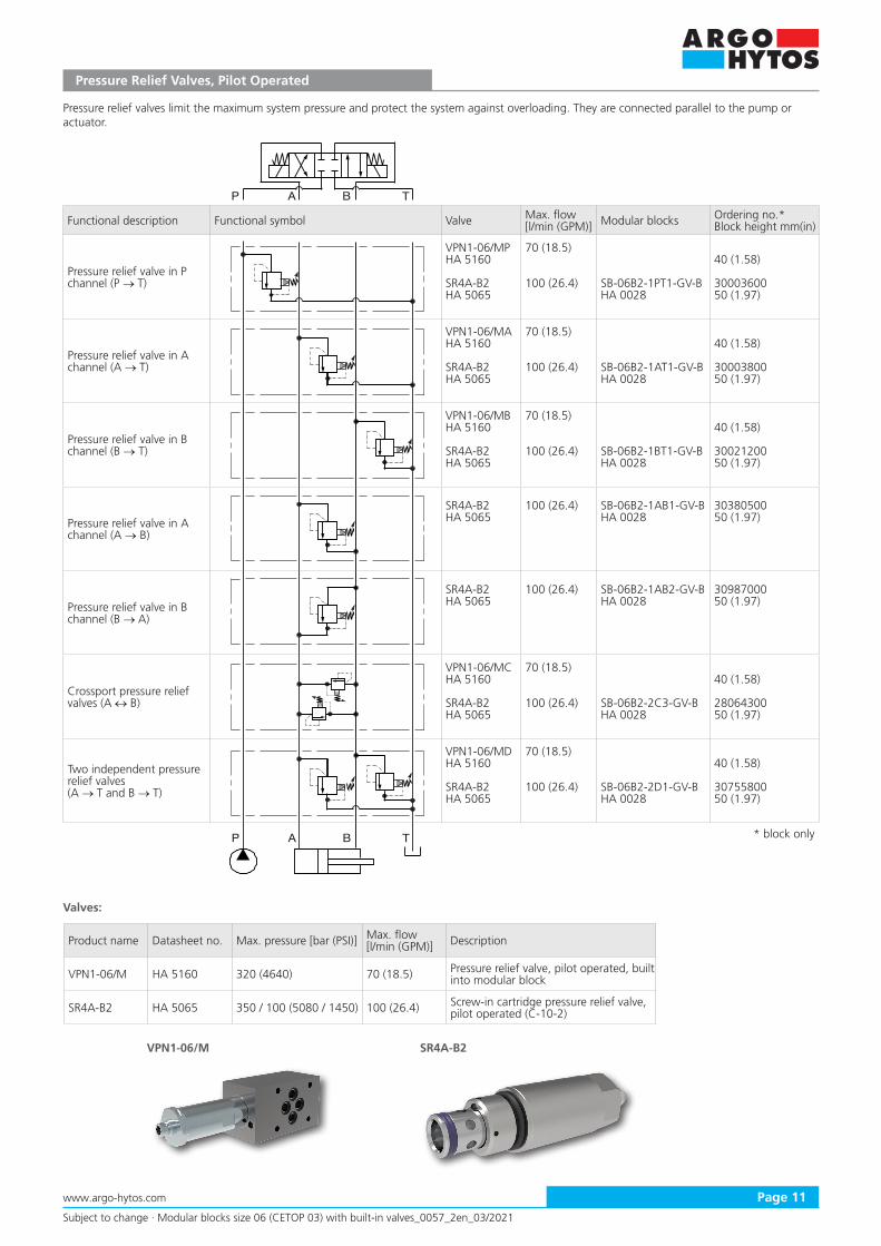
Pressure Relief Valves, Pilot Operated
Pressure relief valves limit the maximum system pressure and protect the system against overloading. They are connected parallel to the pump or actuator.
Functional description Functional symbol Valve Max. flow [l/min (GPM)] Modular blocks Ordering no.*
Block height mm(in)
Pressure relief valve in P channel (P → T)
VPN1-06/MPHA 5160
SR4A-B2HA 5065
70 (18.5)
100 (26.4) SB-06B2-1PT1-GV-BHA 0028
40 (1.58)
3000360050 (1.97)
Pressure relief valve in A channel (A → T)
VPN1-06/MAHA 5160
SR4A-B2HA 5065
70 (18.5)
100 (26.4) SB-06B2-1AT1-GV-BHA 0028
40 (1.58)
30003800 50 (1.97)
Pressure relief valve in B channel (B → T)
VPN1-06/MBHA 5160
SR4A-B2HA 5065
70 (18.5)
100 (26.4) SB-06B2-1BT1-GV-BHA 0028
40 (1.58)
30021200 50 (1.97)
Pressure relief valve in A channel (A → B)
SR4A-B2HA 5065
100 (26.4) SB-06B2-1AB1-GV-BHA 0028
3038050050 (1.97)
Pressure relief valve in B channel (B → A)
SR4A-B2HA 5065
100 (26.4) SB-06B2-1AB2-GV-BHA 0028
3098700050 (1.97)
Crossport pressure relief valves (A ↔ B)
VPN1-06/MCHA 5160
SR4A-B2HA 5065
70 (18.5)
100 (26.4) SB-06B2-2C3-GV-BHA 0028
40 (1.58)
28064300 50 (1.97)
Two independent pressure relief valves (A → T and B → T)
VPN1-06/MDHA 5160
SR4A-B2HA 5065
70 (18.5)
100 (26.4) SB-06B2-2D1-GV-BHA 0028
40 (1.58)
30755800 50 (1.97)
Valves:
Product name Datasheet no. Max. pressure [bar (PSI)] Max. flow[l/min (GPM)] Description
VPN1-06/M HA 5160 320 (4640) 70 (18.5) Pressure relief valve, pilot operated, built into modular block
SR4A-B2 HA 5065 350 / 100 (5080 / 1450) 100 (26.4) Screw-in cartridge pressure relief valve, pilot operated (C-10-2)
* block only

P A B T
P A B T
T
P
/p
ma
xp
min
P A B T
P A B T
SR4P2-B2
Subject to change · Modular blocks size 06 (CETOP 03) with built-in valves_0057_2en_03/2021
www.argo-hytos.comPage 12
Pressure Relief Valves Operated by Solenoid
The solenoid operated relief valves switch between two adjusted pressure values or adjusted maximum and minimum system pressure (combined relief and unloading function). The pressure values are adjusted mechanically with the help of two adjusting screws.
Functional description Functional symbol Valve Max. flow [l/min (GPM)] Modular blocks Ordering no.*
Block height mm(in)
Pressure relief / unloading valve in P channel (P → T), switching between adjusted p1 and p2
SR4E-B2HA 5068
60 (15.9) SB-06B2-1PT1-GV-BHA 0028
3000360050 (1.97)
Valves:
Product name
Datasheet no.
Max. pressure [bar (PSI)]
Max. flow[l/min (GPM)] Description
SR4E-B2 HA 5068 350 / 100 (5080 / 1450)
60 (15.9) Screw-in cartridge pressure relief valve operated by solenoid (C-10-2)
Proportional Pressure Relief Valves
The valves enable continuous adjustment of the maximum system pressure depending on the command control signal. The valves with a negative characteristic create the maximum pressure at zero control signal (opposite function)
Functional description Functional symbol Valve Max. flow [l/min (GPM)] Modular blocks Ordering no.*
Block height mm(in)
Continuous adjustment of maximum pressure in P channel (P → T)
SR4P2-B2HA 5117
SRN4P1-B2HA 5138
80 (21.1)
80 (21.1)
SB-06B2-1PT1-GV-BHA 0028
SB-06B2-1PT1-GV-BHA 0028
3000360050 (1.97)
3000360050 (1.97)
Valves:
Product name
Datasheet no.
Max. pressure [bar (PSI)]
Max. flow[l/min (GPM)] Description
SR4P2-B2 HA 5117 350 / 100 (5080 / 1450)
80 (21.1)Screw-in cartridge proportional pressure relief valve, pilot operated (C-10-2)
SRN4P1-B2 HA 5138 350 / 100 (5080 / 1450)
80 (21.1)Screw-in cartridge proportional pressure relief valve with negative characteristic, pilot operated (C-10-2)
* block only
* block only

P A B T
P A B T
M
M
M
M
SP2A-B3VRP2-06
Subject to change · Modular blocks size 06 (CETOP 03) with built-in valves_0057_2en_03/2021
www.argo-hytos.com Page 13
Pressure Reducing Valves, Direct Acting
Reducing valves maintain a constant set pressure. They are often used for adjusting the pressure on an actuator, it means the force acting on the piston rod or the torque on the shaft of hydraulic motor. Three-way valves protect the pipeline leading to the actuator against pressure overloading as a relief valves and allow the back flow from the actuator to the tank.
Functional description Functional symbol Valve Max. flow [l/min (GPM)] Modular blocks Ordering no.*
Block height mm(in)
Reduced pressure setting in P channel, additionally gauge port M
VRP2-06-PHA 5145
SP2A-B3HA 5146
50 (13.2)
60 (15.9) SB-06B3-1P2-GV-BHA 0028
40 (1.58)
3078640050 (1.97)
Reduced pressure setting in A channel, bypass check valve for back flow, additionally gauge port M
VRP2-06-AHA 5145
50 (13.2)45 (1.77)
Reduced pressure setting in B channel, bypass check valve for back flow, additionally gauge port M
VRP2-06-EHA 5145
50 (13.2)45 (1.77)
Reduced pressure setting in P channel, the valve controlled by pressure in B channel, additionally gauge port M
VRP2-06-BHA 5145
50 (13.2)40 (1.58)
Valves:
Product name Datasheet no. Max. pressure [bar (PSI)] P, A, B / T
Max. flow[l/min (GPM)] Description
VRP2-06 HA 5145 350 / 210 (5080 / 3050) 50 (13.2) Pressure reducing-relieving valve, direct acting, built into modular block
SP2A-B3 HA 5146 420 / 200 (6090 / 2900) 60 (15.9) Screw-in cartridge reducing-relieving valve, direct acting (C-10-3)
* block only

P A B T
P A B T
M
M
M
M
M
SP4A-B3VRN2-06
Subject to change · Modular blocks size 06 (CETOP 03) with built-in valves_0057_2en_03/2021
www.argo-hytos.comPage 14
Pressure Reducing Valves, Pilot Operated
Reducing valves maintain a constant set pressure. They are often used for adjusting the pressure on an actuator, it means the force acting on the piston rod or the torque on the shaft of hydraulic motor. Three-way valves protect the pipeline leading to the actuator against pressure overloading as a relief valves and allow the back flow from the actuator to the tank. Pilot operated valves need permanent small flow through the pilot stage to assure the continuous constant pressure regulation.
Functional description Functional symbol Valve Max. flow [l/min (GPM)] Modular blocks Ordering no.*
Block height mm(in)
Reduced pressure setting in P channel, additionally gauge port M
VRN2-06/MPHA 5155
SP4A-B3HA 5144
40 (11)
60 (15.9) SB-06B3-1P2-GV-BHA 0028
45 (1.77)
30786400 50 (1.97)
Reduced pressure setting in A channel, additionally gauge port M
SP4A-B3HA 5144
60 (15.9) SB-06B3-1A2-GV-BHA 0028
2806440050 (1.97)
Reduced pressure setting in A channel, bypass check valve for back flow, additionally gauge port M
VRN2-06/MAHA 5155
40 (11)45 (1.77)
Reduced pressure setting in B channel, bypass check valve for back flow, additionally gauge port M
VRN2-06/MBHA 5155
40 (11)45 (1.77)
Reduced pressure setting in B channel, additionally gauge port M
VRN2-06/MCHA 5155
40 (11)45 (1.77)
Valves:
Product name Datasheet no. Max. pressure [bar (PSI)] P, A, B / T
Max. flow[l/min (GPM)] Description
VRN2-06 HA 5155 320 / 160 (4640 / 2320) 40 (11) Pressure reducing-relieving valve, pilot operated, built into modular block
SP4A-B3 HA 5144 350 / 100 (5080 / 1450) 60 (15.9) Screw-in cartridge reducing-relieving valve, pilot operated (C-10-3)
* block only
P A B T
P A B T
M
SP4P2-B3
P A B T
A B TP
SS4A-A3
Subject to change · Modular blocks size 06 (CETOP 03) with built-in valves_0057_2en_03/2021
www.argo-hytos.com Page 15
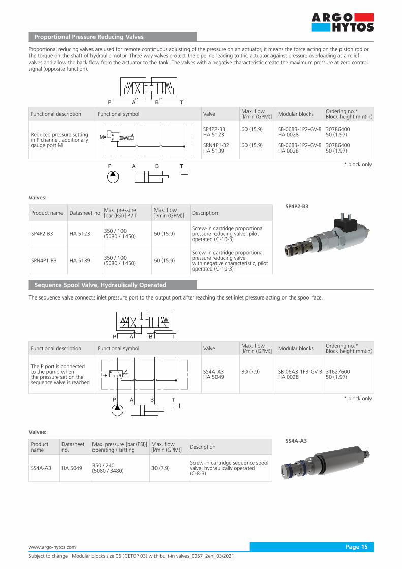
Proportional Pressure Reducing Valves
Proportional reducing valves are used for remote continuous adjusting of the pressure on an actuator, it means the force acting on the piston rod or the torque on the shaft of hydraulic motor. Three-way valves protect the pipeline leading to the actuator against pressure overloading as a relief valves and allow the back flow from the actuator to the tank. The valves with a negative characteristic create the maximum pressure at zero control signal (opposite function).
Functional description Functional symbol Valve Max. flow [l/min (GPM)] Modular blocks Ordering no.*
Block height mm(in)
Reduced pressure setting in P channel, additionally gauge port M
SP4P2-B3HA 5123
SRN4P1-B2HA 5139
60 (15.9)
60 (15.9)
SB-06B3-1P2-GV-BHA 0028
SB-06B3-1P2-GV-BHA 0028
3078640050 (1.97)
3078640050 (1.97)
Valves:
Product name Datasheet no. Max. pressure [bar (PSI)] P / T
Max. flow[l/min (GPM)] Description
SP4P2-B3 HA 5123 350 / 100(5080 / 1450) 60 (15.9)
Screw-in cartridge proportional pressure reducing valve, pilot operated (C-10-3)
SPN4P1-B3 HA 5139 350 / 100(5080 / 1450) 60 (15.9)
Screw-in cartridge proportional pressure reducing valve with negative characteristic, pilot operated (C-10-3)
Sequence Spool Valve, Hydraulically Operated
The sequence valve connects inlet pressure port to the output port after reaching the set inlet pressure acting on the spool face.
Functional description Functional symbol Valve Max. flow [l/min (GPM)] Modular blocks Ordering no.*
Block height mm(in)
The P port is connected to the pump when the pressure set on the sequence valve is reached
SS4A-A3HA 5049
30 (7.9) SB-06A3-1P3-GV-BHA 0028
3162760050 (1.97)
Valves:
Product name
Datasheet no.
Max. pressure [bar (PSI)]operating / setting
Max. flow[l/min (GPM)] Description
SS4A-A3 HA 5049 350 / 240(5080 / 3480) 30 (7.9)
Screw-in cartridge sequence spool valve, hydraulically operated (C-8-3)
* block only
* block only

P A B T
P A B T
SOB5A-BP3/HSO5A-BP3/H
Subject to change · Modular blocks size 06 (CETOP 03) with built-in valves_0057_2en_03/2021
www.argo-hytos.comPage 16
Overcenter Valves
Overcenter valves ensure the load position when the pump is off and enable continuous, safe movement control of the load acting in the movement (negative) direction of the actuator, which is accelerated by load. Non-balanced and fully balanced valves with ventilation of spring space are available.
Functional description Functional symbol Valve Max. flow [l/min (GPM)] Modular blocks Ordering no.*
Block height mm(in)
Non-balanced overcenter valve in A channel, cont-rolled by pressure from B channel
SO5A-BP3/HHA 5199
40 (11) SB-06BP3-1A1-GV-BHA 0028
4107290053 (2.09)
Non-balanced overcenter valve in B channel, cont-rolled by pressure from A channel
SO5A-BP3/HHA 5199
40 (11) SB-06BP3-1B1-GV-BHA 0028
4105420053 (2.09)
Non-balanced overcenter valves in A and B channels, crossport controlled
SO5A-BP3/HHA 5199
40 (11) SB-06BP3-2C2-GV-BHA 0028
4104720053 (2.09)
Fully balanced overcenter valve in A channel, cont-rolled by pressure from B channel
SOB5A-BP3/HHA 5197
40 (11) SB-06BP3-1A1-GV-BHA 0028
4107290053 (2.09)
Fully balanced overcenter valve in B channel, cont-rolled by pressure from A channel
SOB5A-BP3/HHA 5197
40 (11) SB-06BP3-1B1-GV-BHA 0028
4105420053 (2.09)
Fully balanced overcenter valves in A and B channels, crossport controlled
SOB5A-BP3/HHA 5197
40 (11) SB-06BP3-2C2-GV-BHA 0028
4104720053 (2.09)
Valves:
Product name Datasheet no. Max. pressure [bar (PSI)] Max. flow[l/min (GPM)] Description
SO5A-BP3/H HA 5199 420 / 350 (6090 / 5080) 40 (11) Screw-in cartridge overcenter valve, non-balanced
SOB5A-BP3/H HA 5197 420 / 350 (6090 / 5080) 40 (11) Screw-in cartridge overcenter valve, fully balanced with atmospheric ventilation
* block only
P A B T
P A B T
Subject to change · Modular blocks size 06 (CETOP 03) with built-in valves_0057_2en_03/2021
www.argo-hytos.com Page 17
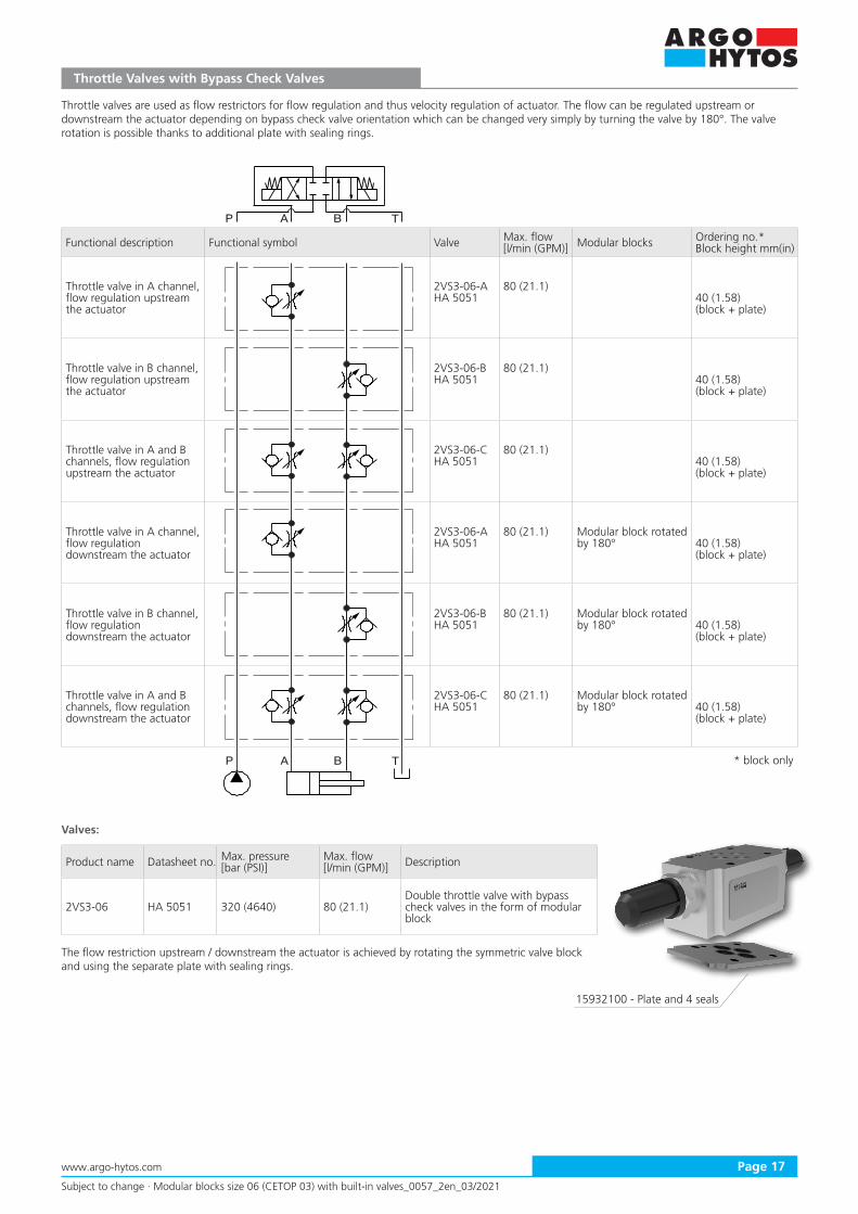
Throttle Valves with Bypass Check Valves
Throttle valves are used as flow restrictors for flow regulation and thus velocity regulation of actuator. The flow can be regulated upstream or downstream the actuator depending on bypass check valve orientation which can be changed very simply by turning the valve by 180°. The valve rotation is possible thanks to additional plate with sealing rings.
Product name Datasheet no. Max. pressure [bar (PSI)]
Max. flow[l/min (GPM)] Description
2VS3-06 HA 5051 320 (4640) 80 (21.1)Double throttle valve with bypass check valves in the form of modular block
The flow restriction upstream / downstream the actuator is achieved by rotating the symmetric valve block and using the separate plate with sealing rings.
Valves:
Functional description Functional symbol Valve Max. flow [l/min (GPM)] Modular blocks Ordering no.*
Block height mm(in)
Throttle valve in A channel, flow regulation upstream the actuator
2VS3-06-AHA 5051
80 (21.1)40 (1.58)(block + plate)
Throttle valve in B channel, flow regulation upstream the actuator
2VS3-06-BHA 5051
80 (21.1)40 (1.58)(block + plate)
Throttle valve in A and B channels, flow regulation upstream the actuator
2VS3-06-CHA 5051
80 (21.1)40 (1.58)(block + plate)
Throttle valve in A channel, flow regulation downstream the actuator
2VS3-06-AHA 5051
80 (21.1) Modular block rotated by 180° 40 (1.58)
(block + plate)
Throttle valve in B channel, flow regulation downstream the actuator
2VS3-06-BHA 5051
80 (21.1) Modular block rotated by 180° 40 (1.58)
(block + plate)
Throttle valve in A and B channels, flow regulation downstream the actuator
2VS3-06-CHA 5051
80 (21.1) Modular block rotated by 180° 40 (1.58)
(block + plate)
* block only
15932100 - Plate and 4 seals
ST21A-A2ST2C1A-A2
ST21A-B2
P A B T
P A B T
Subject to change · Modular blocks size 06 (CETOP 03) with built-in valves_0057_2en_03/2021
www.argo-hytos.comPage 18
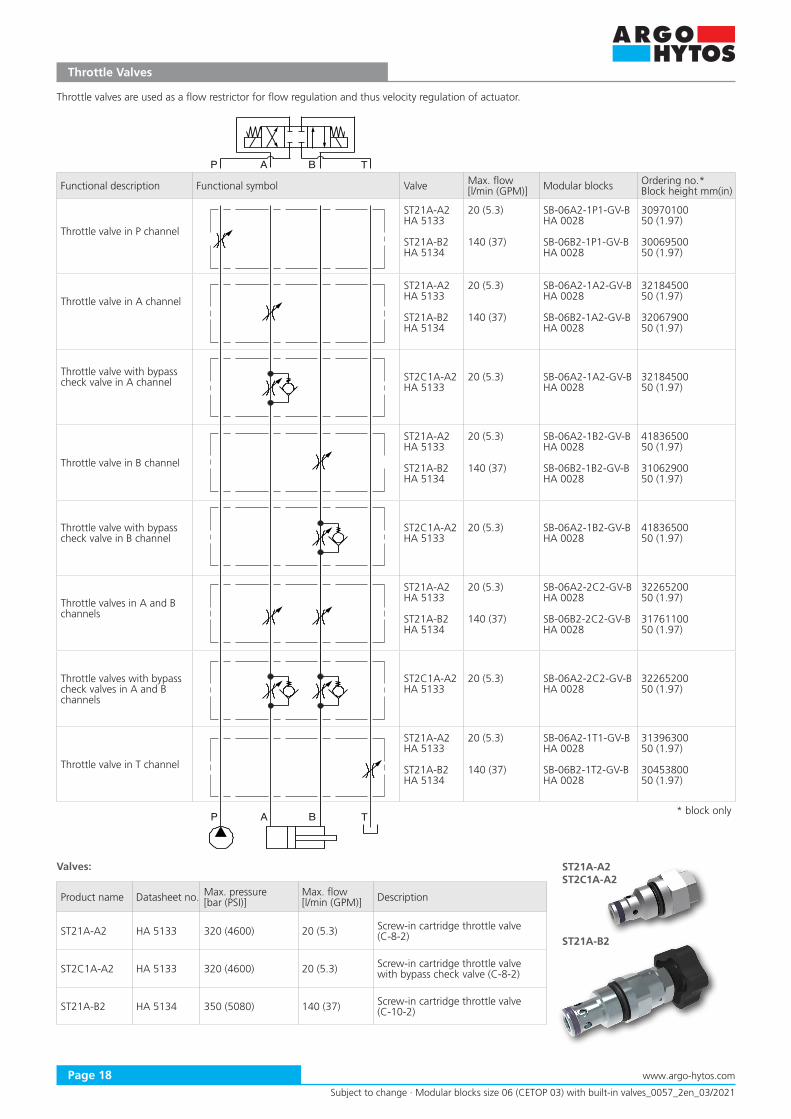
Throttle Valves
Functional description Functional symbol Valve Max. flow [l/min (GPM)] Modular blocks Ordering no.*
Block height mm(in)
Throttle valve in P channel
ST21A-A2HA 5133
ST21A-B2HA 5134
20 (5.3)
140 (37)
SB-06A2-1P1-GV-BHA 0028
SB-06B2-1P1-GV-BHA 0028
3097010050 (1.97)
3006950050 (1.97)
Throttle valve in A channel
ST21A-A2HA 5133
ST21A-B2HA 5134
20 (5.3)
140 (37)
SB-06A2-1A2-GV-BHA 0028
SB-06B2-1A2-GV-BHA 0028
3218450050 (1.97)
3206790050 (1.97)
Throttle valve with bypass check valve in A channel ST2C1A-A2
HA 513320 (5.3) SB-06A2-1A2-GV-B
HA 00283218450050 (1.97)
Throttle valve in B channel
ST21A-A2HA 5133
ST21A-B2HA 5134
20 (5.3)
140 (37)
SB-06A2-1B2-GV-BHA 0028
SB-06B2-1B2-GV-BHA 0028
4183650050 (1.97)
3106290050 (1.97)
Throttle valve with bypass check valve in B channel
ST2C1A-A2HA 5133
20 (5.3) SB-06A2-1B2-GV-BHA 0028
4183650050 (1.97)
Throttle valves in A and B channels
ST21A-A2HA 5133
ST21A-B2HA 5134
20 (5.3)
140 (37)
SB-06A2-2C2-GV-BHA 0028
SB-06B2-2C2-GV-BHA 0028
3226520050 (1.97)
3176110050 (1.97)
Throttle valves with bypass check valves in A and B channels
ST2C1A-A2HA 5133
20 (5.3) SB-06A2-2C2-GV-BHA 0028
3226520050 (1.97)
Throttle valve in T channel
ST21A-A2HA 5133
ST21A-B2HA 5134
20 (5.3)
140 (37)
SB-06A2-1T1-GV-BHA 0028
SB-06B2-1T2-GV-BHA 0028
3139630050 (1.97)
3045380050 (1.97)
Valves:
Product name Datasheet no. Max. pressure [bar (PSI)]
Max. flow[l/min (GPM)] Description
ST21A-A2 HA 5133 320 (4600) 20 (5.3) Screw-in cartridge throttle valve (C-8-2)
ST2C1A-A2 HA 5133 320 (4600) 20 (5.3) Screw-in cartridge throttle valve with bypass check valve (C-8-2)
ST21A-B2 HA 5134 350 (5080) 140 (37) Screw-in cartridge throttle valve (C-10-2)
Throttle valves are used as a flow restrictor for flow regulation and thus velocity regulation of actuator.
* block only

P A B T
P A B T
Subject to change · Modular blocks size 06 (CETOP 03) with built-in valves_0057_2en_03/2021
www.argo-hytos.com Page 19
Flow Control Valves with Two-way Pressure Compensator
Flow control valves with two-way pressure compensator maintain a set flow rate independent of the pressure induced by load and supply pressure fluctuation. Constant pressure drop on the valve and thus the constant flow rate is maintained by throttling.
Functional description Functional symbol Valve Max. flow [l/min (GPM)] Modular blocks Ordering no.*
Block height mm(in)
Flow control valve with 2-way pressure compensator in P channel
VSS3-062/MHA 5050
SF22A-B2HA 5067
40 (11)
40 (11) SB-06B2-1P2-GV-BHA 0028
40 (1.58)
3001810050 (1.97)
Flow control valve with 2-way pressure compensator in A channel, flow regulation upstream the actuator
VSS1-206-xA-11HA 5032
SF22A-B2HA 5067
22 (5.8)
40 (11) SB-06B2-1A1-GV-BHA 0028
40 (1.58)
3002150050 (1.97)
Flow control valve with 2-way pressure compensator in A channel, flow regulation downstream the actuator
SF22A-B2HA 5067
40 (11) SB-06B2-1A2-GV-BHA 0028
3206790050 (1.97)
Flow control valve with 2-way pressure compensator and bypass check valve in A channel, flow regulation upstream the actuator
VSS1-206-xB-11HA 5032
22 (5.8)40 (1.58)
Flow control valve with 2-way pressure compensator and bypass check valve in A channel, flow regulation downstream the actuator
VSS1-206-xC-11HA 5032
22 (5.8)40 (1.58)
Flow control valve with 2-way pressure compensator in B channel, flow regulation upstream the actuator
SF22A-B2HA 5067
40 (11) SB-06B2-1B1-GV-BHA 0028
3070810050 (1.97)
Flow control valve with 2-way pressure compensator in B channel, flow regulation downstream the actuator
SF22A-B2HA 5067
40 (11) SB-06B2-1B2-GV-BHA 0028
3106290050 (1.97)
Flow control valve with 2-way pressure compensator in T channel
SF22A-B2HA 5067
40 (11) SB-06B2-1T1-GV-BHA 0028
3164800050 (1.97)
* block only

P A B T
P A B T
SF32A-B3/H VSS1-306
VSS3-06/M VSS1-206 SF22A-B2
Subject to change · Modular blocks size 06 (CETOP 03) with built-in valves_0057_2en_03/2021
www.argo-hytos.comPage 20
Valves:
Product name Datasheet no. Max. pressure [bar (PSI)]
Max. flow[l/min (GPM)] Description
VSS3-06/M HA 5050 320 (4640) 40 (11) Flow control valve with 2-way pressure compensator built into modular block
VSS1-206 HA 5032 320 (4640) 22 (5.8)Flow control valve with 2-way pressure compensator and bypass check valve built into modular block
SF22A-B2 HA 5067 350 (5080) 40 (11) Screw-in cartridge flow control valve with 2-way pressure compensator (C-10-2)
Flow Control Valves with Three-way Pressure Compensator Bypass Type
Flow control valves with three-way pressure compensator bypass type maintain a set flow rate independent of the pressure induced by load and supply pressure fluctuation. Constant pressure drop on the valve and thus the constant flow rate is maintained by dividing the flow. Undesired flow for actuator function is diverted to tank.
Functional description Functional symbol Valve Max. flow [l/min (GPM)] Modular blocks Ordering no.*
Block height mm(in)
Flow control valve with 3-way pressure compensator bypass type in P channel
VSS1-306HA 5033
SF32A-B3/HHA 5070
16 (4.2)
50 (13.2) SB-06B3-1P4-GV-BHA 0028
40 (1.58)
3388120060 (2.36)
Valves:
Product name Datasheet no. Max. pressure [bar (PSI)]
Max. flow[l/min (GPM)] Description
VSS1-306 HA 5033 320 (4640) 16 (4.2) Flow control valve with 3-way pressure compensator built into modular block
SF32A-B3/H HA 5070 350 (5080) 50 (13.2)Screw-in cartridge flow control valve with 3-way pressure compensator(C-10-3)
* block only

LS
LS
LS
LS
X2
P A B T
P A B T
Subject to change · Modular blocks size 06 (CETOP 03) with built-in valves_0057_2en_03/2021
www.argo-hytos.com Page 21
Pressure Compensators
Pressure compensators are used for stabilisation of pressure drop on valves. When used with proportional directional control valves they assure repeatability of flow regulation at the load or supply fluctuation. Two-way pressure compensator regulates the pressure drop by throttling of the flow, three-way pressure compensator by flow dividing. The two-way pressure compensator has two possible connections. Meter-in connection is used for positively acting load, meter-out connection is used for negatively acing load (in the moving direction of actuator).
Functional description Functional symbol Valve Max. flow [l/min (GPM)] Modular blocks Ordering no.*
Block height mm(in)
Two-way pressure compensator in P channel, meter-in connection, controlled by pressure from A channel, additionally port for LS regulation
TV2-062/MAHA 5166
35 (9.3)40 (1.58)
Two-way pressure compensator in P channel, meter-in connection, controlled by pressure from B channel, additionally port for LS regulation
TV2-062/MBHA 5166
35 (9.3)40 (1.58)
Two-way pressure compensator in P channel, meter-in connection, controlled by pressure from A or B channel via load shuttle valve, additionally port for LS regulation
TV2-062/MCHA 5166
35 (9.3)40 (1.58)
Two-way pressure compensator in P channel, meter-in connection, controlled by pressure from A or B channel via load shuttle valve, additionally 2 ports for LS regulation
TV2-062/MCXHA 5166
35 (9.3)40 (1.58)
Two-way pressure compensator with bypass check valve in A and B channels, meter-out connection
TV2-062/MDHA 5166
35 (9.3)63.5 (2.5)
Two-way pressure compensator with bypass check valve in A channel, meter-out connection
TV2-062/MEHA 5166
35 (9.3)63.5 (2.5)
Two-way pressure compensator with bypass check valve in B channel, meter-out connection
TV2-062/MFHA 5166
35 (9.3)63.5 (2.5)
Three-way pressure compensator controlled by pressure from A channel
TV2-063/MAHA 5168
40 (11)40 (1.58)
Three-way pressure compensator controlled by pressure from B channel
TV2-063/MBHA 5168
40 (11)40 (1.58)
Three-way pressure compensator controlled by pressure from A and B channels via load shuttle valve
TV2-063/MCHA 5168
40 (11)40 (1.58)
* block only
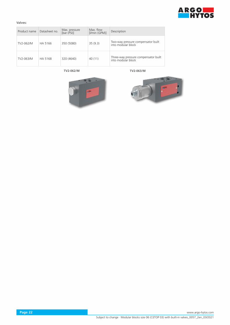
TV2-062/M TV2-063/M
Subject to change · Modular blocks size 06 (CETOP 03) with built-in valves_0057_2en_03/2021
www.argo-hytos.comPage 22
Valves:
Product name Datasheet no. Max. pressure [bar (PSI)]
Max. flow[l/min (GPM)] Description
TV2-062/M HA 5166 350 (5080) 35 (9.3) Two-way pressure compensator built into modular block
TV2-063/M HA 5168 320 (4640) 40 (11) Three-way pressure compensator built into modular block

Subject to change · Modular blocks size 06 (CETOP 03) with built-in valves_0057_2en_03/2021
www.argo-hytos.com Page 23
Base Manifold
Base manifold DP6 with built-in pressure relief valve is designed for assembly of one (CETOP) valve with body or integrated modular assembly. It has been designed for hydraulic powerpacks but can be used separately.
Product name Datasheet no. Material / Max. pressure [bar (PSI)]
Max. flow [l/min (GPM)] Description
DP6-06 HA 0012 Steel / 350 (5080) 50 (13.2) Base manifold with built-in pressure relief valve
Subplates DP
Subplates DP-06 are used for connection of one (CETOP) valve with body or integrated modular assembly. The under side is provided with threaded ports for fittings and pipeline connection.
C. Subplates and Manifolds
Integrated modular blocks create a flexible control assembly, which is connected to the hydraulic circuit with the help of subplate or base block provided threaded side ports.
Product name Datasheet no. Material / Max. pressure [bar (PSI)] Description
DP-06 HA 0002 Gray cast iron / 350 (5080) Subplate
Parallel Circuit Manifolds with Side Ports
Parallel circuit manifolds DR2-06 enable multiple vertical integration by extending the number of connecting patterns (from 1 to 10). Plates are produced from low carbon steel or mechanically hardened aluminium alloy ENAW 7575, specified for working pressure up to 320 bar. The front section can be fitted optionally with a built-in pressure relief valve and unloading valve (P-T). Each section is designed to control one actuator.
Product name Datasheet no. Material / Max. pressure [bar (PSI)] Description
DR2-06 HA 0026 Aluminium alloy / 320 (4640)Steel / 350 (5080) Parallel circuit manifolds with common P and T channels

ZB06 PD06
12
3
BA
TPBA
PT
A B
P T
4
4
1
2
3
Subject to change · Modular blocks size 06 (CETOP 03) with built-in valves_0057_2en_03/2021
www.argo-hytos.comPage 24
Base Manifolds with a Connected Parallel Circuit Manifolds
The base manifold is a multifunctional part for connection of parallel circuit manifold with groups of integrated valves, creating the control circuit. The base manifold enables connection to the pump and back pipeline in the building the complete hydraulic drives. The upper surface is designed for connection of PD06 parallel circuit manifold with vertically integrated modular valves. Side connecting pattern DN06 is designed for (CETOP) valve with body, which is used for drive control.
Product name Datasheet no. Material / Max. pressure [bar (PSI)]
Max. flow [l/min (GPM)] Description
ZB06 HA 0010 Aluminium alloy / 250 (3630) Steel / 320 (4640) 50 (13.2) Base manifold for power packs
PD06 HA 0006 Aluminium alloy / 250 (3630)Parallel circuit manifold with common P and T channels designed for assembly to the base manifold ZB06
Connection example of the hydraulic power pack using a base manifold (1) with a control valve (2) on the side face. The parallel circuit manifolds PD (3) with vertically grouped modular valves (4) is connected with bolts to the upper surface of the base manifold.

5,4
(0.2
1)
10 (0.39)10 (0.39)
8,8
(0.3
5)
20 (0.79)
14,5 (0.57)
M5
15 (0.59)L
M5
10 (0.39)
M5
Subject to change · Modular blocks size 06 (CETOP 03) with built-in valves_0057_2en_03/2021
www.argo-hytos.com Page 25
D. Fastening Material
Fastening material for vertical integration of modular valves and the calculation of the length of studs and screws can be found in Datasheet no. HA 0020.
Metric Threads dimensions in millimeters (in)
Studnut M5Studrod M5xL (lenght L see the table) Strenght class - GR.8 ISO 10.9
Calculating of Stud Length
Calculation formula: L = LP + ∑HM + LB + LN
L - total length of the studrodLP -thread length projection into subplate / block = 10 mm (0.39 in)∑HM - SUM of all heights of all installed sandwich valves LB - length of directional valve projection = 37.3 mm (1.47 in)LN - length of thread in the nut (LNmin - LNmax) = 6 mm (0.24 in) - 14 mm (0.55 in)
Studrods - order numbers of separate elements or kits
M5 Torque to 8.9 Nm (6.6 lbf.ft)
Item Length L Weight Item number Max. pressure
[mm] kg / 100 pcs 1pc Kit* [bar]
Studrod 70 1.0 20197400 16103500 350Studrod 77 1.1 15609500 16105100 350Studrod 82 1.2 20197600 16103600 350Studrod 88 1.2 16679400 16105200 350Studrod 93 1.3 24233200 33884500 350Studrod 98 1.4 20197800 16103700 350Studrod 102 1.4 20197900 16103800 350Studrod 110 1.6 15609700 16103900 350Studrod 115 1.6 20198100 16108200 350Studrod 120 1.8 20198200 23678300 350Studrod 125 1.8 24233300 33884800 350Studrod 130 1.8 15609600 16104000 350Studrod 136 1.9 15609800 16104100 350Studrod 144 2.0 20198500 16104200 350Studrod 150 2.1 20198600 33885000 350Studrod 158 2.2 20198700 33885200 320Studrod 166 2.3 20198800 23686800 320Studrod 170 2.4 16679500 16104300 320Studrod 177 2.5 20199000 16108300 320Studrod 180 2.5 20199100 16104500 320Studrod 185 2.6 20199200 16104600 320Studrod 190 2.7 20199300 23679200 320Studrod 202 3.0 20199400 16105300 320Studrod 210 3.1 20199500 16104700 250Studrod 215 3.2 20199600 16104800 250Studrod 222 3.3 20199700 16104900 250Studrod 230 3.4 20199800 33885600 250Studrod 242 3.4 23698400 23685200 250Studrod 250 3.5 20199900 16105500 200Studrod 255 3.6 20200000 16105000 200Studrod 262 3.7 20200100 16105400 200Nut M5 0.7 15630800
Caution!*Kits include 4 studrods + 4 nuts

Subject to change · Modular blocks size 06 (CETOP 03) with built-in valves_0057_2en_03/2021
www.argo-hytos.comPage 26
Remarks:
This document is intented to aid circuit creation by means of vertical integration and identification of modular blocks in relation to their individual valves. If the required modular valve was not found in the above selection, we recommend you the following procedure:
› Select the required valve from the constantly updated product catalogue at www.argo-hytos.com › Available blocks for specific valve are listed in the table “Technical Data” of datasheet. › Select the appropriate modular block for screw-in cartridge valves according to type and function of the valve in datasheet no. HA 0028. › In the same way, you can choose in-line body for screw-in cartridge valves from datasheet SB 0018. › If you need to make the cavity for screw-in cartridge valve in your own block, cavity drawings and the associated tools are found
in datasheet SMT 0029. › It is possible to realize different hydraulic function using the unified type of block. E.g. the same block type 1PT1 can be used for pressure
relief valve and appropriate type of unloading valve. › Generally, there is a recommendation to not connect pressure line (P) to the electric operated valves in such way that the solenoid core
tube is loaded by undesired pressure peaks. These valves should be connected to the pump in radial direction. › Connection symbols of pilot operated poppet valves (one-way valves) and pressure valves show their connection which is necessary for
their proper function. For better understanding see data sheets of the valves. › If the required modular blocks is not listed, please contact our sales department.