compact magnetic wheeled robot with high mobility … magnetic wheeled robot with high mobility for...
TRANSCRIPT

Compact Magnetic Wheeled Robot With High Mobility for InspectingComplex Shaped Pipe Structures
Fabien Tache, Wolfgang Fischer,Roland Siegwart
Autonomous Systems Lab(http://www.asl.ethz.ch)
Eidgenossische TechnischeHochschule Zurich (ETHZ)8092 Zurich, Switzerland
{ftache,wfischer,rsiegwart}@ethz.ch
Roland MoserALSTOM (Switzerland) Ltd
ALSTOM Power Service(http://www.alstom.com)5401 Baden, Switzerland
Francesco MondadaLaboratoire de Systemes
Robotiques (http://lsro.epfl.ch)Ecole Polytechnique Federale de
Lausanne (EPFL)1015 Lausanne, [email protected]
Abstract— This paper describes a compact robot with twomagnetic wheels in a bicycle arrangement, which is intendedfor inspecting the inner casing of pipes with complex shapedstructures. The locomotion concept is based on an adaptedmagnetic wheel unit integrating two lateral lever arms. Thesearms allow for slightly lifting off the wheel in order to locallydecrease the magnetic force, as well as laterally stabilizingthe wheel unit. The robot has the main advantage to becompact and mechanically simple. It features 5 active degreesof freedom: 2 driven wheels each equipped with an active lifter-stabilizer and 1 steering unit. This paper also presents thedesign and implementation of a prototype robot and its highmobility is shown. It is able to pass 90◦ convex and concaveobstacles with any inclination regarding the gravity. Finally, itonly requires limited space to maneuver, since turning on spotaround the rear wheel is possible.
I. INTRODUCTION
Using mobile robots carrying sensing tools for internalpipe inspection is an attractive alternative to conventionalinspection methods. By avoiding disassembling complexstructures or excavating deep pipe constructions, inspectionand then outage time can be saved. Furthermore, thesesystems allow for inspecting locations that are not reachableusing conventional tools.
As mentioned in [1], [2] and [3], many locomotion systemswere developed for maneuvering about in different kinds ofpipe environments. When climbing ability is required, themost common solution is to use spreading systems [3], whichare not suitable for environment with high abrupt diameterchanges. In these cases, the locomotion concept is combinedwith an attachment system such as grasps, suction cups [4],adhesive polymers [5] or (electro) magnetic elements.
The in-pipe environment considered in this paper requiresa compact locomotion system with climbing ability, as wellas a high degree of mobility for negotiating obstacles. Theenvironment is a complex structure with narrow sections,high abrupt diameter changes and inclined elements. Sincethe first attachment concepts listed above usually imply com-plex mechanics and since the environment is ferromagnetic,magnetic wheels were selected [6] for this application.
The following state of the art then focuses on mobile ro-bots with magnetic elements and describes their limitations.Simple compact systems such as Magnebots [7], Tripod [8],Osaka Gas inspection robot [9] and Nanomag [10] have alimited mobility. They are not designed for passing obstacles:they can at most travel on slightly curved surfaces (e.g. onthe outside of tanks) or go over small size steps (smaller thanthe wheel radius).
In comparison, Fischer [11], Yukawa [12] and Kawaguchi[13] robots implemented special mechanisms to negotiatespecific complex obstacles. The first two are designed forvertical walls and the outer surfaces of pipes. They aim topass difficult obstacles such as sharp ridges which do notprovide magnetic attraction force, but these robots require alot of space and many DoF. The last one is more related tothis work, since it is designed for inspecting the inner casingof pipes, but can only pass over a single step obstacle thanksto a passive wheel mechanism.
Fig. 1. Compact robot with two magnetic wheels in bicycle arrangement
A previous paper [6] describes in details why the existinglocomotion systems cannot be used in this very restrictiveenvironment and proposes a novel adapted magnetic wheel

unit allowing for negotiating complex obstacles. This paperthen presents the design and implementation of a compacttwo wheels robot with bicycle wheel configuration (Fig. 1)based on this concept. The prototype proves the feasibilityof the concept and tests show the high mobility of the robotwhich can negotiate complex obstacles.
The paper is organized as follows. After having presentedthe characteristics of the challenging environment in SectionII, Section III reminds the concept of the adapted magneticwheel unit and its advantages towards mobility and miniatur-ization. Design considerations are then explained in SectionIV. While the robot implementation is described in SectionV, preliminary results obtained with the first prototype arepresented in Section VI. After having described the currentprototype limitations, improvements and future work areproposed.
II. REQUIREMENTS: APPLICATION AND ROBOTNECESSARY MOBILITY
This section gives an overview of a specific ferromagneticenvironment for which non-destructive testing (NDT) isdesired and the challenges it addresses to the necessarylocomotion system.
g
200 mm
Tripple step
Gap
50 mm
(a1)
(b)
(d)(d)
(c2)
(c1)(e)
700 mm(a2)
Fig. 2. 3D CAD model of a typical environment
An efficient inspection robot allows for bringing the in-spection sensor to any location in the environment. Here isthe list of the application requirements, as depicted on the3D CAD model (Fig. 2):
a) the wide range of inner diameters encountered. The di-ameter varies from 200mm (this defines the maximumrobot space envelope) up to 700mm.
b) the local abrupt inner diameter changes, up to 50mmon Figure 2. These can be seen as 90◦ convex orconcave obstacles.
c) the complex arrangement and sequence of these obsta-cles such as triple steps or gap.
d) the environment is composed of horizontal pipe el-ements, as well as vertical elements. Generally anyinclination can be encountered. Climbing ability is thenrequired.
e) The locomotion system has to be able to maneuver(turn on spot) in narrow locations and to be able totravel on circumferential paths, which can also haveany orientation regarding gravity.
Furthermore, since the system is intended for inspection,it has to embed NDT sensors. Thus the robot should be ableto carry its own mass plus some extra payload (estimatedto 500g) corresponding to the mass of the sensors andtheir manipulation tools. Finally, the inspection system mustnot damage the environment. Every part which is in directcontact with it has to be equipped with a protecting material,typically rubber.
III. 2 + 4 WHEELS LOCOMOTION CONCEPT
As analyzed in [6], it is a complex task to design auniversal system able to face any combination of 90◦ surfacetransitions. In this previous paper, it is also shown that anadapted wheel (Fig. 3) is necessary to get rid of the unwantedmagnetic force (Fmag2), when one or several wheels are incontact with 2 different surfaces (e.g. a 90◦ concave edge).
Fmag1Fmag1
Fmag2Fmag2
Fig. 3. The lever arm mechanism is applied, in order to slightly lift offthe wheel and locally decrease the unwanted magnetic force Fmag2 [6]
Among the potential wheels configurations illustrated inFigure 4, arrangements 2©, 3© and 4© have a major problem:there is a magnetic force decrease, when the wheels arenot standing perpendicularly to the pipe surface (Fig. 5,bottom). The best solution to avoid this problem would be toimplement complex passive mechanics with virtual center ofrotation on the wheel-to-surface contact point as illustrated inFigure 5 (right). This solution allows for ensuring a maximalmagnetic adhesion (Fig. 5, top), but unfortunately uses toomuch space, is complex and heavy. On the other hand, the2 aligned wheels (bicycle wheel configuration) arrangement1© in Fig. 4, which is not dependant on the pipe diameter,
has the main drawback to be laterally unstable.
1
2
3
4
Side view
Front view
5
Magnetic wheel Non-magnetic wheelMagnetic or non-magnetic contact point
Fig. 4. 2 to 4 wheels arrangements: matrix of top view regarding side andfront views [6]

The chosen locomotion concept consists in assembling twoadapted magnetic wheels unit integrating an active rotarylifter mechanism (Fig.3), which can also be used as wheelstabilizer. Indeed, this compromise including 2 + 4 wheels(configuration 5© in Fig. 4) has the advantages of the 2aligned wheels robots: it is mechanically much simplerand consequently smaller than other wheel configurations.Moreover, it can be laterally stabilized thanks to the 4 lateralnon-magnetic wheels.
FFmagmag FFmagmag
αα*F*Fmagmagαα*F*Fmagmag
Fig. 5. Left: magnetic wheel without and with ground adaptation. Right:example of a 3 magnetic wheels robot with cumbersome passive mechanicsand actuators
This paper then presents the design and implementation ofa robot (Fig. 1) with 2 aligned magnetic wheels integratingthe lifter-stabilizer function. Steering is ensured thanks toan active DoF on the front wheel and surface adaptation isensured thanks to the free joint in the fork (Fig. 6). Thissystem has then the main advantages to have high mobilitywhile being mechanically simple and compact. It only has 5active DoF (2 driven wheels, 1 active steering and 2 lifter-stabilizer arms pairs) and 1 free joint.
Steering actuatorFree joint
Fig. 6. The free joint on the fork allows for adapting to differentenvironments: flat or curved surface
IV. ROBOT DESIGNA robot which can drive on surfaces with any orientation
regarding gravity requires special design attention. In orderto avoid the robot to fall, to ensure stability, to allow climbingand obstacle passing ability, a good compromise between themagnetic force of the wheels, the robot mass and the powerof the actuators has to be found.
This section then presents the robot model, the mainassumptions, the worst cases and their consequences on thedesign.
A. Magnetic wheels tests
Since data about magnetic wheel performance (relationbetween the magnetic force Fmag , its mass and size) arenecessary for the calculation, some tests were performed.
Fmag_ref 0.4 * Fmag_ref
15°
Fmag_ref
Fmag_ref 0.4 * Fmag_ref
a b c
Fig. 7. Main results of the magnetic wheel tests
The most critical results are illustrated in Figure 7:a) the magnetic force of a tilted wheel decreases to 75%
at 3◦, 55% at 10◦ and even 40% at only 15◦.b) the same reference magnetic force (Fmag ref ) is mea-
sured on both contact points for a wheel positioned ona 90◦ concave edge.
c) the magnetic force decreases fast on sharp edges: 40%of the reference force when the wheel is positioned ona 90◦ convex edge.
B. Robot model: forces and torques
The following forces and torques are considered in therobot model (Fig. 8): the magnetic forces (Fmag ix), therobot weight which includes the payload (mg), the actuatortorques Ti, the traction forces (Tr ix) and the reaction forces(Rix) which define the necessary friction coefficient (µix =Tr ix/Rix). The main mechanical dimensions used are therobot length L, the wheel diameter r and the position of thecenter of mass (xCM , zCM ).
gg
TT11TT22
mgmg
FFmag_2amag_2a
RR2b2b
RR2a2a
RR1a1a
FFmag_2bmag_2b
FFmag_1amag_1a
TTr_2ar_2a
TTr_2br_2b TTr_1ar_1aµµ2a2aµµ2b2b
µµ1b1b
LL
rr
zzCMCM
xxCMCM
Fig. 8. Forces model of the robot
The static equilibrium force and torque equations werecalculated for all robot positions on various obstacles and theresults analyzed, in order to extract the worst cases, whichare described afterwards.
C. Necessary magnetic force
The magnetic force aims to ensure that the wheel does notlose contact (Fig. 9a), but also provides enough traction force

to move. Assuming a minimum friction coefficient µ of 0.5(measured), the absolute worst case is to ensure that the robotis able to provide enough traction when climbing a doublestep, on the ceiling, when one wheel is on a sharp edge andthe other needs to get detached from a double contact point asdepicted on Figure 9b. This case sets the minimum magneticforce. The force should however not be over-dimensioned tominimize the load on the lifting mechanism.
a b c
Fig. 9. Worst cases. (a): not loosing contact, (b): not slipping, (c): maximalwheel actuator torque
D. Necessary wheel actuator torque
The wheels actuators have to be strong enough to drive therobot in any situations. For the wheels actuators, two worstcases can be distinguished. The absolute worst case happenswhen the robot is climbing vertically and 1 wheel cannotprovide much traction (Fig. 9c). This calculation determinesthe absolute maximum intermittent load on the wheel motor.The worst case, determining the maximum continuous loadon the wheels actuators, happens when the robot climbs avertical wall for a long time.
E. Necessary lifter actuator torque
Concerning the lifters actuators, the worst case happenswhen a wheel has to be lifted in the narrowest tube (re-spectively 200mm of diameter). Indeed, in this situation thelifter lever arm (xlift) is the longest and the lifter forceFlift = (Fmag + mg/2) × L/(L − xlift) is the highest.The required torque Tlift = Flift × xlift is then maximum.Since the lifter only works in intermittent mode, there is nocontinuous load worst case.
Fmag
mg
Flift
L
r
xlift Fmag
Flift/2 Flift/2mg
Fig. 10. Worst case regarding lifter-stabilizer actuator torque: lifting thewheel in the narrowest tube
F. Necessary steering actuator torque
The steering torque (Ts) necessary to turn the front wheelcan be deduced from the wheel geometry and the frictionforces (Ffr i) between the wheel and the surface: Ts = µ×
(Fmag +mg/2)×b/2. The steering torque is high for a robotequipped with magnetic wheels, due to the magnetic forceswhich are several times higher than the robot weight.
gTsteer
Ts
αg
Tsteer
Ts
Ffr_1 Ffr_2Fmag
Rmg
Fmag
R
α
β1
TTssFFfr_1fr_1
FFfr_2fr_2
µ
b
β2
Fig. 11. Necessary steering torque
The effective torque (Tsteer) of the steering actuatordepends on the robot geometry and its location in theenvironment as depicted in Figure 11. The steering axis isinclined from an angle α to satisfy the ground clearanceconstraint on sharp obstacles (Fig. 13c). This inclination isalso set, so that the angle β between the steering axis and thesurface normal vector remains small for extreme positions ofthe robot: on a flat surface (Fig. 11, left) and on a curvedsurface (Fig. 11, right).
V. IMPLEMENTATION
Now that the main design issues have been presented, thefeasibility of the concept is demonstrated by a prototypeimplementation. This section explains the main constraints inthe implementation process of the magnetic wheel bicycle,composed of 2 adapted wheel units, of which one can besteered.
A. Wheel unit
The main challenge is to implement a compact wheelunit integrating the coaxial wheel and lifter mechanisms andtheir actuators. As illustrated in schematic 12, the followingchoices have been made:
• Both actuators (wheel and lifter) have been positionedon top of the wheel for compactness.
• The power transmission (wheel and lifter) is ensured by2 stages of spur gears, one on each side of the wheel.
• Collision with obstacle in front of the wheel unit mustalso be avoided (Fig. 12, right).
B. Steering unit and assembly
The robot is then the assembly of two similar wheel unitsand a steering unit that is added to the front wheel. Thefollowing constraints require special attention:
• There must be no mechanical collisions, when the frontwheel is steered at 90◦ in the narrowest space as shownin Figure 6 (right).
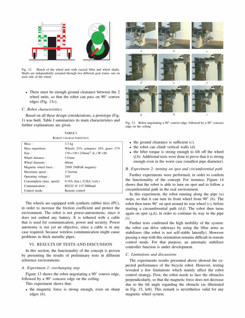
Fig. 12. Sketch of the wheel unit with coaxial lifter and wheel shafts.Shafts are independently actuated through two different gear trains: one oneach side of the wheel
• There must be enough ground clearance between the 2wheel units, so that the robot can pass on 90◦ convexedges (Fig. 13c).
C. Robot characteristics
Based on all these design considerations, a prototype (Fig.1) was built. Table I summarizes its main characteristics andfurther explanations are given.
TABLE IROBOT CHARACTERISTICS
Mass : 3.3 kgMass repartition: Wheels: 23%, actuators: 18%, gears: 17%Size : 170×130×220mm3 (L×W×H)Wheel distance : 115mmWheel diameter : 60mmMagnetic wheel force : 250N (NdFeB magnets)Maximum speed : 2.7m/minOperating voltage : 24VConsumption (max. speed): 0.19A (hor.), 0.28A (vert.)Communication : RS232 @ 115’200baudControl mode: Remote control
The wheels are equipped with synthetic rubber tires (PU),in order to increase the friction coefficient and protect theenvironment. The robot is not power-autonomous, since itdoes not embed any battery. It is tethered with a cablethat is used for communication, power and security. Powerautonomy is not yet an objective, since a cable is in anycase required, because wireless communication might causeproblems in thick metallic pipes.
VI. RESULTS OF TESTS AND DISCUSSION
In this section, the functionality of the concept is provenby presenting the results of preliminary tests in differentreference environments.
A. Experiment 1: overhanging step
Figure 13 shows the robot negotiating a 90◦ convex edge,followed by a 90◦ concave edge on the ceiling.
This experiment shows that:• the magnetic force is strong enough, even on sharp
edges (b).
a b c
d e f
g h i
Fig. 13. Robot negotiating a 90◦ convex edge, followed by a 90◦ concaveedge on the ceiling
• the ground clearance is sufficient (c).• the robot can climb vertical walls (d).• the lifter torque is strong enough to lift off the wheel
(f,h). Additional tests were done to prove that it is strongenough even in the worst case (smallest pipe diameter).
B. Experiment 2: turning on spot and circumferential path
Further experiments were performed, in order to confirmthe functionality of the concept. For instance, Figure 14shows that the robot is able to turn on spot and to follow acircumferential path in the real environment.
In this experiment, the robot running along the pipe (a)stops, so that it can turn its front wheel from 90◦ (b). Therobot then turns 90◦ on spot around its rear wheel (c), beforestarting a circumferential path (d-f). The robot then turnsagain on spot (g,h), in order to continue its way in the pipe(i).
Further tests confirmed the high mobility of the system:the robot can drive sideways by using the lifter arms asstabilizers (the robot is not self-stable laterally). Howeverpassing a step with this orientation remains difficult in remotecontrol mode. For that purpose, an automatic stabilizercontroller function is under development.
C. Limitations and discussions
The experiments results presented above showed the ex-pected performance of the bicycle robot. However, testingrevealed a few limitations which mainly affect the robotcontrol strategy. First, the robot needs to face the obstaclesperpendicularly, so that the magnetic force does not decreasedue to the tilt angle regarding the obstacle (as illustratedin Fig. 15, left). This remark is nevertheless valid for anymagnetic wheel system.

a b c
d e f
g h i
Fig. 14. Robot turning on spot and then following a circumferential path(real environment)
Another limitation comes from the two aligned drivenwheels structure and the irreversibility of their power trans-mission trains. This wheel configuration implies a goodcontrol strategy: powering one wheel does not allow forforcing the movement of the other one, moreover a badspeed (or torque) repartition between them implies the robotdeformation or slippage (which should be avoided on a robotwhich is intended to climb).
Fig. 15. Necessity to maintain ground contact. Left: correctly approachingthe obstacle. Right: reducing wheel distance when turning
The same remark implies when the robot steers its frontwheel to 90◦ position. Indeed, the wheel distance has tobe controlled, in order to avoid the front wheel tilt and amagnetic force decrease as depicted on Figure 15 (right).Next developments address these issues.
VII. CONCLUSION AND FUTURE WORK
In this paper, an in-pipe environment, for which a mo-bile robot brings attractive advantages over conventionalinspection methods is presented. Its complex shaped structurerequires a locomotion system with a high degree of mobility,in order to negotiate complex combinations of step obstacleswith several inclinations regarding gravity. Based on theconcept of an adapted magnetic wheel unit already proposedin [6], a two-wheeled robot with bicycle wheel configurationis proposed, implemented and tested.
This robot has the advantage to be compact and mechan-ically simple. It only has 5 active DoF and 1 free joint,moreover the aligned wheel arrangement makes it almostindependent of the pipe radius. The preliminary experimentsshowed that the robot mobility fulfills the application re-quirements and that the concept is feasible.
At the moment, the robot can be remote controlled by atrained user that has a good overview on the scene. However,since this will not be the case in the real closed environment,an automatic control is required. Ongoing work first consistsin integrating sensors that help ensuring a correct distancebetween the wheels, in order to avoid the robot deformation(or slippage) and to ensure front wheel contact when steering.Moreover, an automatic stabilizer arms positioning system isnecessary. Later on, higher level control functionalities willbe implemented, in order to decrease the user interactionwith the active system.
VIII. ACKNOWLEDGEMENTSWe would like to thank Gilles Caprari for his fruitful ad-
vices and ALSTOM for supporting this work as explorationresearch.
REFERENCES
[1] B.Bruce, R.Gordon, M.Sullivan, and C.Neary, “Internal repair ofpipelines - technology status assessment report,” Edison WeldingInstitute, Columbus, USA, Tech. Rep. DE-FC26-02NT4163, 2002.
[2] H.Schempf, “In-pipe-assessment robot platforms - phase I - state-of-the-art review,” CMU, Pittsburgh, USA, Report to National EnergyTechnology Laboratory REP-GOV-DOE-20041102, Nov. 2004.
[3] S. Roh and H. R. Choi, “Differential-drive in-pipe robot for movinginside urban gas pipelines,” IEEE Transactions on Robotics, vol. 21,no. 1, pp. 1–17, Feb. 2005.
[4] F.Cepolina, R.C.Michelini, R.P.Razzoli, and M.Zoppi, “Gecko, aclimbing robot for walls cleaning,” in International Workshop onAdvances in Service Robotics (ASER03), Bardolino, Italy, Mar. 2003.
[5] M. Greuter, G. Shah, G. Caprari, F. Tache, R. Siegwart, and M. Sitti,“Toward micro wall-climbing robots using biomimetic fibrillar ad-hesives,” in Proc. of the International Symposium on AutonomousMinirobots for Research and Edutainment (AMIRE’2005), Fukui,Japan, Sept. 2005.
[6] F. Tache, W. Fischer, R. Moser, F. Mondada, and R. Siegwart,“Adapted magnetic wheel unit for compact robots inspecting complexshaped pipe structures,” in Proc. of the 2007 IEEE/ASME InternationalConference on Advanced Intelligent Mechatronics (AIM’2007), Zurich,Switzerland, Sept. 2007.
[7] A. H.Slocum, S. Awtar, and J. Hart, “Magnebots - a magnetic wheelsbased overhead transportation concept,” in Proc. of the 2nd IFACConference on Mechatronics Systems, Berkeley, USA, Dec. 2002.
[8] Jireh Industries LTD. (2007, July). [Online]. Available:http://www.jireh-industries.com
[9] T. Sogi, Y. Kawaguchi, H. Morisaki, K. Ohkawa, N. Kai, andH. Hayakawa, “Inspection robot for spherical storage tanks,” in Proc.of the 26th International Conference on Industrial Electronics Controland Instrumentation (IECON’2000), Nagoya, Japan, Oct. 2000.
[10] Inuktun. (2006, July). [Online]. Available: http://www.inuktun.com[11] W.Fischer, F.Tache, and R.Siegwart, “Magnetic wall climbing robot
for thin surfaces with specific obstacles,” in Proc. of the InternationalConference on Field and Service Robotics (FSR’07), Chamonix,France, July 2007.
[12] T. Yukawa, H. Okano, and S. Komatsubara, “Mechanisms for themovement of piping inspection robot with magnetic elements,” inProc. of the Sixth IASTED International Conference on Robotics andApplications (RA’05), Cambridge, USA, Nov. 2005.
[13] Y.Kawaguchi, I.Yoshida, H.Kurumatani, T.Kikuta, and Y.Yamada,“Internal pipe inspection robot,” in Proc. of the IEEE InternationalConference on Robotics and Automation (ICRA’95), Nagoya, Japan,May 1995, pp. 857–862.