comp-jt with dynamic cell selection, global precoding...
TRANSCRIPT
International Journal of Wireless & Mobile Networks (IJWMN) Vol. 7, No. 3, June 2015
DOI : 10.5121/ijwmn.2015.7303 27
COMP-JT WITH DYNAMIC CELL SELECTION, GLOBAL PRECODING MATRIX
AND IRC RECEIVER FOR LTE-A
Heba Raafat Ahmed 1
, Essam Sourour 2 and Hassan M. Elkamchouchi
3
1Department of Electrical Engineering, Pharos University, Alexandria, Egypt
2,3Department of Electrical Engineering, Alexandria University, Alexandria, Egypt
ABSTRACT
Coordinated multi-point transmission and reception (CoMP) is introduced in LTE-A to mitigate co-channel
interference and improve the cell-edge user experience. In this paper we propose a joint transmission
scheme for LTE-CoMP and we enhance the performance of CoMP with two techniques: 1- dynamic MIMO
cell selection and 2- closed loop MIMO with global precoding matrix selection. A cell-edge user selects the
base stations that jointly transmit the desired signal from the available ones (we assumed 3). The user also
selects the closed loop precoding matrices for MIMO in a joint fashion to fit the independent MIMO
channels from two base stations (eNBs). In addition, edge users are likely to be subject to severe Co-
channel interference from eNBs outside the joint transmission set.To address co-channel interference from
the base station(s) that are not included in CoMP joint transmission set, the user equipment employs
Minimum Mean Squared Error receiver with Interference Rejection Combining (MMSE-IRC). We illustrate
the effect of fading correlation between elements of the transmit and receive antennas. Also, the effect of
the desired to interference eNB power ratio in case of medium correlation for 3 and 4 layers using MMSE-
IRC receiver is studied. Also we compare the BER performance for 3 and 4 layers in case of different
values of the desired to interference eNB power ratio. Simulation results show that the performance of
CoMP with cell selection considerably improves the performance. Also, global selection of the precoding
matrices outperforms local selection. In addition, using MMSE-IRC gives much better performance than
the conventional minimum mean square error (MMSE) in the presence of co-channel interference.
KEYWORDS
LTE-A; CoMP; MIMO; Joint transmission; Codebook; Capacity; MMSE; MMSE-IRC.
1.INTRODUCTION
The Long Term Evolution (LTE) Release 10 (Rel-10) broadband network is developed by the
Third Generation Partnership Project (3GPP) and denoted as LTE-Advanced (LTE-A). LTE-A is
expected to be the dominating mobile communication system in the near future. LTE-A targets 1
Gb/s downlink (DL) and 500 Mb/s uplink (UL) throughputs to meet the IMT-Advanced
requirements [1]-[5].
The performance improvements of LTE-Advanced are achieved with advanced physical layer
techniques including carrier aggregation, enhanced. Interference coordination techniques, and
enhanced multiple-antenna schemes (MIMO) [6]-[9].
In 3GPP LTE/LTE-A Release 8-10, partial DL channel state information is provided to the eNB
transmitter through the closed loop MIMO mode. Codebook-based MIMO precoding technique

International Journal of Wireless & Mobile Networks (IJWMN) Vol. 7, No. 3, June 2015
28
has been used to reduce the feedback overhead [6]. The user equipment (UE) selects and feeds
back the precoding matrix index (PMI) together with channel quality indicator (CQI) to the eNB.
In this paper we extend the closed-loop MIMO concept to be used with CoMP-JT. [3].
So there are two ways for mitigating interference and improving the cell-edge user performance
in Long Term Evolution-Advanced (LTE-A) system. First method is coordinated multi-point
transmission and reception (CoMP) and second method is interference rejection combining (IRC)
receiver, which is explained below.
One of the major enhancements in LTE-A is the employment of CoMP technology. In the
downlink, CoMP allows multiple eNBs to transmit to a UE collaboratively. This is done through:
a) Dynamic Point Selection (DPS), i.e., dynamic selection of the transmission point, b) Joint
Transmission (JT), i.e., transmitting the same information from multiple eNBs to the same UE
coherently, or c) Coordinated Scheduling/Beam-forming (CS/CB) [10],[11]. eNBs communicate
with one another through the backhaul network such as X2 interface via fiber optics. Figures 1, 2,
and 3 show three different schemes for CoMP [12]. Among these three types of DL CoMP
techniques this paper is interested in JT. JT is particularly promising in the presence of co-
channel interference because the signals transmitted from multiple eNBs are coherently combined
by the UE in a constructive manner, achieving high SINR and throughput for the UE [13, 14].
Figure 1. Joint Transmission cooperative (JT).
Figure 2. Dynamic Point Selection cooperative (DPS).
Figure 3. Coordinated scheduling/beam forming (CS/CB).
In our previous work, e.g., [15], we studied the performance of downlink CoMP-JT with closed-
loop MIMO in LTE-A networks. Edge UEs receive the desired signal from two eNBs: serving
eNB and remote eNB. Each eNB applies a precoding matrix to the vector of transmitted
modulation symbols. For compatibility with LTE specifications, the precoding codebook of LTE-
A [16] is used. We denote the conventional method for selecting the precoding matrix as the local

International Journal of Wireless & Mobile Networks (IJWMN) Vol. 7, No. 3, June 2015
29
precoding scheme. In this scheme the UE selects the precoding matrix for each eNB based on its
corresponding channel, as depicted in figure 4. On the other hand, in the global precoding scheme
the UE selects the two precoding matrices for the serving and remote eNBs jointly to fit the
distributed channel from the two eNBs. Both the local and global precoding require the same
number of feedback bits. However, the global precoding scheme requires more search in the UE.
To enhance CoMP performance, in this paper we consider the case when the UE is allowed to
select the two jointly transmitting eNBs which makes considerable improvement. We show that
combining the cell selection and precoding matrix selection techniques alleviate the severity of
the interferenceThe cost is extra UE processing, extra feedback bits and backhaul overhead.
To further combat inter-cell interference the UE employs Interference Rejection Combining
(IRC) based on the Minimum Mean Square Error (MMSE) criteria. IRC has been recently
proposed to mitigate co-channel interference for edge users [17]-[21]. The conventional MMSE
receiver treats the interference as being independent across the receive antennas (i.e., white
interference). MMSE-IRC is a straightforward extension to the MMSE receiver employing the
correlation matrix of the interfering signal across the receive antennas. Due to its simplicity,
MMSE-IRC has replaced MMSE as the baseline MIMO receiver in LTE-A systems [22].
In this paper we couple the CoMP, which is the interference mitigation method from the network
side, with MMSE-IRC as the interference mitigation method from the UE side.
To confirm the achieved performance gain we also study the effect of fading correlation among
MIMO antennas. In addition, the effect of the desired to interference eNB power ratio in case of
medium correlation for 3 and 4 layers using MMSE-IRC receiver is studied. Also we compare the
BER performance for 3 and 4 layers in case of different values of the desired to interference eNB
power ratio.
1.1.Related Work
It is known that, at low mobility, closed-loop MIMO outperforms open-loop MIMO (obviously at
the cost of feedback overhead) [6]. Enhancing CoMP-JT performance with closed loop MIMO is
generally suggested in the literature [13, 14]. However, specific implementation, performance
analysis and tradeoffs have not been sufficiently studied. In [11] closed loop MIMO precoding is
considered for CoMP. A global precoding matrix codebook is created using a clustering
algorithm from a large number of channel samples, generated through simulation. While the
designed codebook matches well to the considered channel model it is not a standard LTE-A. In
[23] Adaptive and distributed CoMP scheduling algorithm, in conjunction with open-loop
MIMO, is proposed which could operate in either JT or CS/CB modes. In order to maximize the
sum-rate of UEs under JT mode, beam-forming matrix is calculated using maximum capacity
criteria. In [12] a general formulation of CoMP JT and DPS is provided. Edge users can switch
between the modes of CoMP or fall back to the single eNB based on channel condition. However,
neither one of the above mentioned references (or, to the best knowledge of the authors, any other
CoMP reference) studied the LTE-A codebook in a closed loop MIMO scheme with CoMP.
Moreover, most CoMP literature focuses on the capacity improvements without providing link
level BER performance. Our current paper covers this gap.
The rest of this paper is organized as follows. Section II presents the system model employed in
this paper. In section III we describe the CoMP-JT eNBs selection algorithm. In Section IV we
present the algorithm for local and global precoding matrix selection with CoMP-JT. In Section V
we provide the MMSE-IRC receiver structure. Section VI is devoted for the simulations result.
Section VII concludes the paper.

International Journal of Wireless & Mobile Networks (IJWMN) Vol. 7, No. 3, June 2015
30
2.CoMP SYSTEM MODEL
We consider the scenario where a cell-edge UE is located at equal distance from 3 eNBs. This
UE, equipped with nr receive antennas, receives the desired signal from two eNBs: serving eNB
and remote eNB. The third eNB becomes a source of inter-cell interference. Each eNB is
equipped with nt transmit antennas and applies a precoding matrix to the vector of transmitted
modulation symbols with nl layers. For LTE compatibility, the precoding codebook of LTE-A
[16] is used. The received signal at subcarrier k at the UE is given by:
( ) ( ) ( ) ( ) ( ), , ,s k s r k r i k ik k k k= + + +y H W H W s H W x v (1)
Where s(k) is a column vector of size nl of desired symbols at subcarrier k. The covariance matrix
of s(k) is given by ls n=C I , where
lnI is the identity matrix of size nl. Similar to s(k), x(k) is a
vector of interfering symbols with the same size and covariance matrix. Also, in (1) H is the
channel matrix with size nr☓nt and W is the precoding matrix with size nt☓nl. The subscripts s, r
and i in (,s k
H , Ws), ( ,r kH , Wr) and (
,i kH , Wi) indicate the serving, remote and interfering eNBs,
respectively. The same precoding matrix is used for all the UE allocated subcarriers. Finally, v(k)
is a vector with size nr representing the AWGN with covariance matrix 1
rv nγ −=C I , where γ is the
average SNR in each receive antenna due to each desired eNB. To simplify notation, in what
follows we may drop the subcarrier index k. The 3 channel matrices H in (1) are independent and
identically distributed (i.i.d). Each channel matrix is correlated according to 1 2 1 2
UE o eN B=H R H R , where RUE and ReNB are the UE and eNB antenna correlation matrices,
respectively. Each element in the nr☓nt channel matrix Ho is independent complex Gaussian with
zero mean and unit variance.
3.DYNAMIC CELL SELECTION
We consider the scenario where the UE is allowed to select the serving and remote eNBs in (1)
from the 3 near-by eNBs. This requires overhead in the backhaul network to make the UE data
available to any 2 eNBs. In addition, at least in our implementation, the UE should acquire the
channel state information for the 3 eNBs. We show in the numerical results that this additional
complexity generously pays-back with performance enhancement.
Inspired by [24, 25], in this paper we propose to use capacity selection criteria for selecting the
two serving eNBs. It is consistently shown ([24] and many similar papers) that other selection
criteria (for example SINR) provide insignificant performance benefit. Denote the estimated
channel matrices from the 3 eNBs to the UE as HeNB1, HeNB2 and HeNB3 (including antenna
correlation). Channel estimation is typically performed using the cell-specific reference signals
transmitted from each eNB [26]. Define [ ]X Y as the matrix formed by concatenating 2 matrices
X and Y. The UE forms the 3 distributed channel matrices: [ ]1 1 2eN B eN B=H H H ,
[ ]2 1 3eN B eN B=H H H and [ ]3 2 3eN B eN B=H H H , each with size nr☓2nt. The UE selects the
two eNBs that maximize the distributed channel capacity. Specifically, the two jointly
transmitting eNBs are selected as follows.

International Journal of Wireless & Mobile Networks (IJWMN) Vol. 7, No. 3, June 2015
31
( ) 2
1log det
t
H
m n m m
k t
CK n
γ = +
∑H I H H , (2)
( )( ){ }1,2 ,3
arg m axselected m
m
C∈
=H H . (3)
In (2), K is the number of allocated subcarriers to the UE. Also AH is the Hermitian of matrix A.
Note that (2) is not the accurate capacity formula since it does not take into account the
interference caused by the third eNB (see for example equation (2) in [27]). However, with
accurate formula no significant difference was found, while large matrix inversion was incurred.
Once, the two jointly transmitting eNBs are decided the next step is to select their precoding
matrices.
4.CoMP-JT PRECODING MATRIX SELECTION
We denote the conventional method for selecting the precoding matrix as the local precoding
scheme. This is the scheme used in closed-loop MIMO without CoMP-JT. In this scheme the UE
selects the precoding matrix for each eNB based on its corresponding channel. On the other hand,
in the global precoding scheme the UE selects the two precoding matrices for the serving and
remote eNBs jointly to fit the distributed channel from the two eNBs. Both the local and global
precoding schemes require the same number of feedback bits. However, the global precoding
scheme requires more processing in the UE. For example, if the number of transmit antennas in
each eNB is 4, the number of precoding matrices in LTE-A codebook is 16 [16]. If the number of
receive antennas in the UE is 4, then in the local precoding scheme the UE searches the two
codebooks separately for each eNB based on each corresponding 4☓4 channel. On the other hand,
in the global precoding scheme the UE searches a global codebook comprising of 16☓16 = 256
precoding matrices of all possible combinations of the two local codebooks. In this case the
distributed channel is 4☓8 joint channel.
4.1.CoMP-JT With Local Precoding Matrix
The received signal from the two eNBs is given by (1). The UE separately selects the best Ws
based on Hs and the best Wr based on Hr according to their respective channel capacity. Several
metrics have been proposed in the literature [24, 25]. SINR maximization criteria provided the
best performance it most cases. Capacity maximization is very slightly inferior but less complex.
Hence, in this paper we employ the capacity maximization criteria. The maximum capacity
criterion is given by:
( ) ( )( )1log det
l
H H
m n m k k m
k
CK
γ= +∑W I W H H W , (4)
{ }( )( )arg max
m
select mW W
C∈
=W W . (5)
The selections in (4) and (5) are repeated separately for Hk = Hs,k and Hk = Hr,k to get Ws and Wr,
respectively. The set of precoding matrices to search is that of LTE-A [16].

International Journal of Wireless & Mobile Networks (IJWMN) Vol. 7, No. 3, June 2015
32
Figure 4. CoMP-JT system with locally selected precoding matrices
4.2.CoMP-JT With Global Precoding Matrix
An alternative approach is to consider the two eNBs as a large distributed antenna array, and the
two channels as one distributed channel H with dimension nr☓2nt. Similar to [11] the UE should
select a single global precoding matrix for this composite channel. We can rewrite (1) as:
( ) ( ) ( ) ( ),k i k ik k k k= + +y H W s H W x v (6)
In (6) Hk is the global channel at subcarrier k and W is the global precoding matrix. These are
given by:
, ,k s k r k = H H H and
TT T
s r = W W W (7)
In (7) AT is the transpose of the matrix A. Now, the global precoding matrix W is selected using
(4) and (5). However, the codebook to select from includes all possible combinations of Ws and
Wr. For example, with 4 transmit antennas the LTE-A codebook includes 16 precoding matrices.
Hence, the global codebook includes 16 x 16 = 256 precoding matrices with all permutations.
5.INTERFERENCE REJECTION COMBINING RECEIVER
Recently, the problem of interference cancellation and suppression has attracted a lot of attention.
Co-channel interference is mitigated by means of several techniques operating either at the
network side (like CoMP) or at the UE receiver (like MMSE-IRC).
In Release 8 LTE the MMSE was considered the baseline MIMO receiver upon which the
minimum performance requirements for the UE are set. This is based on the assumption that co-
channel interference from adjacent cells is uncorrelated across the receive antennas. To mitigate
the effect of co-channel interference release 11 LTE introduced MMSE-IRC receivers as the
baseline. Fig.5 describe the scenarios where the MMSE receiver and MMSE-IRC receiver should
be used.

International Journal of Wireless & Mobile Networks (IJWMN) Vol. 7, No. 3, June 2015
33
Figure 5. MMSE-IRC receiver.
Here, we employ MMSE-IRC with CoMP-JT. At this point the jointly transmitting eNBs and
their precoding matrices have been selected. We now modify the received signal (1) as:
( ) ( ) ( ) ( ) ( ) ( )1
ik k k k k kf
= + +y G s G x v . (8)
Comparing to (1), ( ) , ,s k s r k rk = +G H W H W is the composite channel matrix of the
desired modulation symbols vector s(k) and ( ) ,i i k ik =G H W is the composite interference channel
matrix of the interference modulation symbols vector x(k). The interference precoding matrix Wi
is randomly selected from the LTE-A codebook [16].
A conventional method to reduce co-channel interference is power control. In (8) the added factor
f is the power ratio between the desired signal from each desired eNB and the interference signal.
This can be considered a form of coordinated scheduling CoMP where the interfering eNB
allocates the same subcarriers to a center UE and reduces the transmit power on these subcarriers.
Note that in LTE-A power control is only for the data carrying subcarriers and not for the cell-
specific reference signals. Hence, the process of joint transmission eNBs selection and precoding
matrix selection described in sections III and IV above is not affected by power control.
The MMSE-IRC symbol estimator is given by [21]:
( )1
1 1 1ˆ H H
s n n
−− − −
= +s C G C G G C y . (9)
In (9) Cn is the covariance matrix for the interference plus noise terms in (8). The conventional
MMSE receiver assumes that interference is uncorrelated across the receiving antennas.
In this case Cn would be given by ( )1 1
rn nfγ − −= +C I . The MMSE-IRC takes the
interference correlation into consideration. In this case in v= +C C C , where Ci is the
interference covariance matrix, which needs to be estimated. Methods for estimating Ci are
available in the literature and are outside the scope of this paper. For example the 3GPP
document [21, section 4.3] provides an algorithm for this estimation using the LTE reference
signals. In this paper we assume perfect knowledge of the interference covariance matrix. Hence,
Cn is given from (8) by:

International Journal of Wireless & Mobile Networks (IJWMN) Vol. 7, No. 3, June 2015
34
( )1 1
r
H
n n i ifγ − −= +C I G G . (10)
Hence, the MMSE-IRC receiver is given by:
( )1
1 1ˆl
H H
n n n
−− −= +s I G C G G C y . (11)
6.SIMULATION RESULTS
A CoMP network with a UE at equal distance from 3 eNBs is simulated. The employed channel
model is the Extended Typical Urban (ETU) and Extended Pedestrian (EPA) specified by LTE
[28, Annex B]. The delay spread of the ETU channel model is higher than the EPA model. Since
antenna correlation has a significant effect on the performance of CoMP and MMSE-IRC we
consider low and medium correlation [29, Annex B]. We compare eNB selection as in section III
above to the case of UE receiving from the first 2 eNBs (denoted as no eNB selection). We also
compare local and global precoding matrix selection. In addition, we compare the performance of
MMSE and MMSE-IRC as in section V. we study the effect of the desired to interference eNB
power ratio f in case of medium correlation for 3 and 4 layers using MMSE-IRC receiver. Also
the BER performance between 3 and 4 layers in case of different values of the desired to
interference eNB power ratio f is compared.
Table I shows the simulation parameters. In this paper, we ignore the feedback latency of the
precoding matrix selection (i.e., sufficiently slow fading channel).
Note that the UE is allocated 5 Resource Blocks (900 kHz). This moderate bandwidth justifies
fixing the precoding matrix over all subcarriers.
All results show the coded BER versus Eb/No , defined by ( )b oE N QRγ= , where γ is the SNR
defined before, R is the code rate and Q is the modulation index.
TABLE I. SIMITULATION PARAMETER
Parameter Value
Number of eNBs 2 desired + 1 interference
TTI size 14 OFDM symbols (normal CP LTE)
System bandwidth 20 MHZ
Channels coding scheme Turbo coding, Log Map, rate R=1/3
Type of receiver MMSE, MMSE-IRC
Modulation scheme QPSK (Q=2)
Number of Resource Blocks for UE 5
Fading channel model ETU, EPA with prefect channel
estimation
Detection algorithm MMSE, MMSE-IRC

International Journal of Wireless & Mobile Networks (IJWMN) Vol. 7, No. 3, June 2015
35
Power ratio desired/interference per eNB f = 0,3,10 dB
Number of transmit antennas = number of receive
antenna nt = nr = 4
Number of layers nl = 3 or 4
Wireless frame Lengths 10ms
Sub-frame length 1 ms
Length of time slot 0.5 ms
Sampling frequency 32.72 MHz
Sub-carrier interval 15KHz
Figure 6 compares local and global precoding matrix in the cases with and without selecting the 2
jointly transmitting eNBs and 1 interference eNB. For this figure we employ low antenna
correlation with ETU channel, f = 3 dB and nl =3 layers using MMSE-IRC receiver. It is clear
from this figure that global precoding matrix selection considerably outperforms local precoding
matrix selection. Also, for both cases, selecting the 2 jointly transmitting eNB provides additional
performance gain. This justifies the extra processing in the UE side.
-4 -3 -2 -1 0 1 2 3 4 510
-5
10-4
10-3
10-2
10-1
100
Eb/N
o in dB
Bit
Err
or
Rate
Global precoding, eNB selection
Global precoding, no selection
Local precoding, no selection
Local precoding, eNB selection
Local precoding
Global precoding
low correlation,ETU channel,3 layers, f =3 dB
Figure 6. BER of global and local precoding matrix in CoMP-JT with and without cell selection at low
correlation using IRC receiver for 3 layers and f = 3 dB under ETU channel model.
Figure 7 repeats that same results of Figure 6 but for EPA channel. Compared to Figure 6, The
ETU channel shows a better performance than the EPA due to the increased frequency
selectivity.

International Journal of Wireless & Mobile Networks (IJWMN) Vol. 7, No. 3, June 2015
36
-4 -2 0 2 4 6 8 1010
-7
10-6
10-5
10-4
10-3
10-2
10-1
100
Eb/N
o in dB
Bit
Err
or
Rate
IRC with global precoding matrix with selection eNBs
IRC with global precoding matrix without selection eNBs
IRC with local precoding matrix with selection eNBs
IRC with local precoding matrix without selection eNBs
global precoding matrix
local precoding matrix
low correlation, EPA channel, 3 layer, f= 3dB
Figure 7. BER of global and local precoding matrix in CoMP-JT with and without cell selection at low
correlation using IRC receiver for 3 layers and f = 3 dB under EPA channel model.
Figure 8 repeats that same results of Figure 6 but for nl = 4 layers. Compared to Figure 6, not
surprisingly the 3 layers case shows lower BER than the 4 layers case. It is interesting to see that
the relative gain that is achieved due to selecting the jointly transmitting eNBs and global
precoding matrix selection is higher than the case of 3 layers. This supports our claim that the
additional processing and overhead needed to implement the techniques presented in this paper
are well paid-back for in terms of improved performance.
-4 -2 0 2 4 6 8 10 12 1410
-6
10-5
10-4
10-3
10-2
10-1
100
Eb/N
o in dB
Bit
Err
or
Rate
IRC with local precoding matrix withoutselection for eNBs
IRC with local precoding matrix with selection for eNBs
IRC with global precoding matrix with selection for eNBs
IRC with global precoding matrix without selection for eNBs
global precoding matrix
local precoding matrix
low correlation ,ETU channel,4 layers,f= 3 dB
Figure 8. BER of global and local precoding matrix in CoMP-JT with and without cell selection at low
correlation using IRC receiver for 4 layers and f = 3 dB under ETU channel model.
Figure 9 repeats that same results of Figure 6 but for MMSE receiver. Compared to Figure 6, it is
clear from these figures that the MMSE-IRC improves the performance considerably compared to
the MMSE.

International Journal of Wireless & Mobile Networks (IJWMN) Vol. 7, No. 3, June 2015
37
-4 -2 0 2 4 6 8 1010
-7
10-6
10-5
10-4
10-3
10-2
10-1
100
Eb/N
o in dB
Bit
Err
or
Rate
MMSEwith global precoding matrix with selection
MMSE with global precoding matrix without selection
MMSE with local precoding matrix without selection
MMSE with local precoding matrix with selection
low correlation ETU channel -3layer
global precoding matrix
local precoding matrix
Figure 9. BER of global and local precoding matrix in CoMP-JT with and without cell selection at low
correlation using MMSE receiver for 3 layers and f = 3 dB under ETU channel model.
Figure 10 repeats that same results of Figure 8 but for MMSE receiver. Compared to Figure 8, it is
clear from these figures that the MMSE-IRC improves the performance considerably compared to
the MMSE.
-4 -2 0 2 4 6 8 10 12 1410
-6
10-5
10-4
10-3
10-2
10-1
100
Eb/N
o in dB
Bit
Err
or
Rate
MMSE with local precoding matrix without selection for eNBs
MMSE with local precoding matrix with selection for eNBs
MMSE with global precoding matrix with selection for eNBs
MMSE with global precoding matrix without selection for eNBs
global precoding matrix
local precoding matrix
low correlation,ETU channel,4 layer,f =3 dB
Figure 10. BER of global and local precoding matrix in CoMP-JT with and without cell selection at low
correlation using MMSE receiver for 4 layers and f = 3 dB under ETU channel model.
Figure 11 repeats that same results of Figure 7 but for MMSE receiver. Compared to Figure 7, it is
clear from these figures that the MMSE-IRC improves the performance considerably compared to
the MMSE.

International Journal of Wireless & Mobile Networks (IJWMN) Vol. 7, No. 3, June 2015
38
-4 -2 0 2 4 6 8 1010
-5
10-4
10-3
10-2
10-1
100
Eb/N
o in dB
Bit
Err
or
Ra
te
MMSE with global precoding matrix with selection eNBs
MMSE with global precoding matrix without selection eNBs
MMSE with local precoding matrix with selection eNBs
MMSE with local precoding matrix without selection eNBs
global precoding matrix
local precodingmatrix
low correlation,EPA channel,3 layers, f = 3 dB
Figures 11. BER of global and local precoding matrix in CoMP-JT with and without cell selection at low
correlation using MMSE receiver for 3 layers and f = 3 dB under EPA channel model.
Figures 12 and 13 compares MMSE and MMSE-IRC in case global and local precoding matrix
respectively and with selecting the 2 jointly transmitting eNBs and 1 interference eNB. For this
figures we employ low antenna correlation with f = 0 dB and nl = 4 layers under ETU channel
model. It clear from figures that the MMSE-IRC improves the performance considerably
compared to the MMSE.
-4 -2 0 2 4 6 8 10 12 1410
-5
10-4
10-3
10-2
10-1
100
Eb/N
o in dB
Bit
Err
or
Rate
MMSE with global precoding matrix with selection eNB
IRC with global precoding matrix with selection eNB
low correlation,ETU channel ,4 layers,f= 0 dB
Figure 12. Comparison between MMSE and MMSE-IRC with global precoding matrix and with cell
selection at low correlation and f = 0 dB under ETU channel model.

International Journal of Wireless & Mobile Networks (IJWMN) Vol. 7, No. 3, June 2015
39
-5 0 5 10 15 2010
-3
10-2
10-1
100
Eb/N
o in dB
Bit
Err
or
Rate
MMSE with local precoding matrix with selection eNB
IRC with local precoding matrix with selection eNB
low correlation, ETU channel,4 layers,f = 0 dB
Figure 13. Comparison between MMSE and MMSE-IRC with local precoding matrix and with cell
selection at low correlation and f = 0 dB under ETU channel model.
Figures 14 and 15 repeat that same results of Figure 6 but for medium antenna correlation under
ETU and EPA channel model respectively. Compared to Figure 6, we can observe an overall
degradation in performance, which is expected to due to the loss in diversity. However, the relative
gain that is achieved due to selecting the jointly transmitting eNBs and global precoding matrix
selection is higher that the case of low correlation. This indicates that the methods described in this
paper are more rewarding in the presence of antenna correlation. By comparing Figures 14 and 15,
we found that the ETU channel shows a better performance than the EPA due to the
increased frequency selectivity.
-5 0 5 10 15 20 2510
-5
10-4
10-3
10-2
10-1
100
Eb/N
o in dB
Bit
Err
or
Rate
Local precoding, eNB selection
Local precoding, no selection
Global precoding, eNB selection
Global precoding, no selection
Global precoding
medium correlation , ETU channel ,3 layers, f = 3 dB
Local precoding
Figure 14. BER of global and local precoding matrix in CoMP-JT with and without cell selection at
medium correlation using IRC receiver for 3 layers and f =3 dB under ETU channel model.

International Journal of Wireless & Mobile Networks (IJWMN) Vol. 7, No. 3, June 2015
40
-5 0 5 10 15 2010
-5
10-4
10-3
10-2
10-1
100
Eb/N
o in dB
Bit
Err
or
Rate
IRC with local precoding matrix without selection for eNBs
IRC with local precoding matrix with selection for eNBs
IRC with global precoding matrix with selection for eNBs
IRC with global precoding matrix without selection for eNBs
Local precoding matrix
global precoding matrix
medium correlation,EPA channel,3 layers ,f= 3 dB
Figure 15. BER of global and local precoding matrix in CoMP-JT with and without cell selection at
medium correlation using IRC receiver for 3 layers and f = 3dB under EPA channel model.
Figure 16 repeats that same results of Figure 8 but for medium antenna correlation. Compared to
Figure 8 we can observe an overall degradation in performance, which is expected to due to the
loss in diversity. However, the relative gain that is achieved due to selecting the jointly
transmitting eNBs and global precoding matrix selection is higher that the case of low correlation.
This indicates that the methods described in this paper are more rewarding in the presence of
antenna correlation.
0 5 10 15 20 25 3010
-5
10-4
10-3
10-2
10-1
100
Eb/N
o in dB
Bit
Err
or
Rate
IRC with local precoding matrix without selection for eNBs
IRC with local precoding matrix with selection for eNBs
IRC with global precoding matrix with selection for eNBs
IRC with global precoding matrix without selection for eNBs
global precoding matrix
local precoding matrix
medium correlation,ETU channel,4 layers,f =3 dB
Figure 16. BER of global and local precoding matrix in CoMP-JT with and without cell selection at
medium correlation using IRC receiver for 4 layers and f =3 dB under ETU channel model.
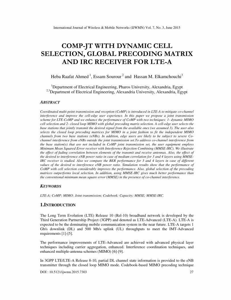
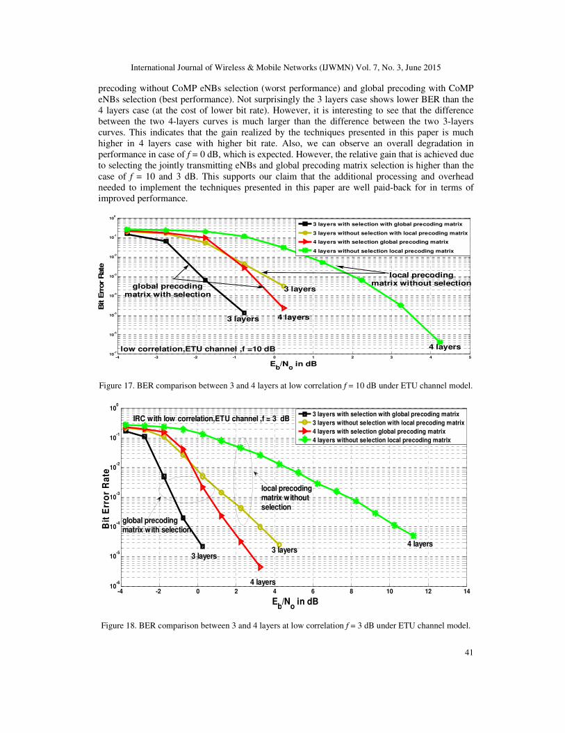
Figures 17, 18 and 19 compare the BER performance of nl =3 and 4 layers in case of f = 10, 3 and
0 dB respectively. To avoid crowding the figure we show only the two extreme cases: local
International Journal of Wireless & Mobile Networks (IJWMN) Vol. 7, No. 3, June 2015
41
precoding without CoMP eNBs selection (worst performance) and global precoding with CoMP
eNBs selection (best performance). Not surprisingly the 3 layers case shows lower BER than the
4 layers case (at the cost of lower bit rate). However, it is interesting to see that the difference
between the two 4-layers curves is much larger than the difference between the two 3-layers
curves. This indicates that the gain realized by the techniques presented in this paper is much
higher in 4 layers case with higher bit rate. Also, we can observe an overall degradation in
performance in case of f = 0 dB, which is expected. However, the relative gain that is achieved due
to selecting the jointly transmitting eNBs and global precoding matrix selection is higher than the
case of f = 10 and 3 dB. This supports our claim that the additional processing and overhead
needed to implement the techniques presented in this paper are well paid-back for in terms of
improved performance.
-4 -3 -2 -1 0 1 2 3 4 510
-7
10-6
10-5
10-4
10-3
10-2
10-1
100
Eb/N
o in dB
Bit E
rror R
ate
3 layers with selection with global precoding matrix
3 layers without selection with local precoding matrix
4 layers with selection global precoding matrix
4 layers without selection local precoding matrix
3 layers
4 layers
3 layers
4 layers
global precodingmatrix with selection
low correlation,ETU channel ,f =10 dB
local precodingmatrix without selection
Figure 17. BER comparison between 3 and 4 layers at low correlation f = 10 dB under ETU channel model.
-4 -2 0 2 4 6 8 10 12 1410
-6
10-5
10-4
10-3
10-2
10-1
100
Eb/N
o in dB
Bit
Err
or
Ra
te
3 layers with selection with global precoding matrix
3 layers without selection with local precoding matrix
4 layers with selection global precoding matrix
4 layers without selection local precoding matrix
local precodingmatrix withoutselection
global precodingmatrix with selection
IRC with low correlation,ETU channel ,f = 3 dB
4 layers
3 layers3 layers
4 layers
Figure 18. BER comparison between 3 and 4 layers at low correlation f = 3 dB under ETU channel model.

International Journal of Wireless & Mobile Networks (IJWMN) Vol. 7, No. 3, June 2015
42
-4 -2 0 2 4 6 8 10 12 1410
-6
10-5
10-4
10-3
10-2
10-1
100
Eb/N
o in dB
Bit
Err
or
Ra
te
3 layers with selection with global precoding matrix
3 layers without selection with local precoding matrix
4 layers with selection global precoding matrix
4 layers without selection local precoding matrix
local precoding matrixwithout selection
IRC with low correlation,ETU channel ,f= 0dB
4 layers
3 layers
4 layers
3 layers
global precodingmatrix with selection
Figure 19. BER comparison between 3 and 4 layers at low correlation f = 0 dB under ETU channel model.
Figures 20, 21, 22 and 23 study the effect of the desired to interference eNB power ratio f in case
of medium correlation for 3 and 4 layers respectively using MMSE-IRC receiver. For Figures 20
and 21 we employ global precoding matrix while Figures 22 and 23 we employ local precoding
matrix. It is clear from those figures that increasing value of f (interference power reduction) gives
better performance. This supports the need for power control in LTE.
-2 0 2 4 6 8 10 1210
-5
10-4
10-3
10-2
10-1
100
Eb/N
o in dB
Bit
Err
or
Ra
te
f= 0 dB
f=10 dB
f= 3 dB
medium correlation,ETU channel,3layers
global precoding matrix with selection for eNBs
Figure 20. BER comparison between different values for f in case of 3 layers at medium correlation using
MMSE-IRC receiver under ETU channel for global precoding matrix with selection.

International Journal of Wireless & Mobile Networks (IJWMN) Vol. 7, No. 3, June 2015
43
0 5 10 15 20 25 3010
-6
10-5
10-4
10-3
10-2
10-1
100
Eb/N
o in dB
Bit
Err
or
Rate
IRC with f= 3 dB
IRC with f= 10 dB
IRC with f= 0 dB
medium correlation ,ETU channel,4layers
global precoding matrix,selection for eNB
Figure 21. BER comparison between different values for f in case of 4 layers at medium correlation using
MMSE-IRC receiver under ETU channel for global precoding matrix with selection.
-5 0 5 10 15 2010
-5
10-4
10-3
10-2
10-1
100
Eb/N
o in dB
Bit
Err
or
Rate
f= 0 dB
f= 10 dB
f= 3 dB
medium correlation ,ETU channel,3 layers
local precoding matrix with selection for eNBs
Figure 22. BER comparison between different values for f in case of 3 layers at medium correlation using
MMSE-IRC receiver under ETU channel for local precoding matrix with selection.

International Journal of Wireless & Mobile Networks (IJWMN) Vol. 7, No. 3, June 2015
44
0 5 10 15 20 25 3010
-5
10-4
10-3
10-2
10-1
100
Eb/N
o in dB
Bit
Err
or
Rate
IRC with f= 3 dB
IRC with f= 0 dB
IRC with f= 10 dB
local precoding matrix withselection for eNBs
medium correlation,ETU channel ,4 layers
Figure 23. BER comparison between different values for f in case of 4 layers at medium correlation using
MMSE-IRC receiver under ETU channel for local precoding matrix with selection.
7.CONCLUSION
In this paper, the LTE-A downlink performance is presented in the case of CoMP-JT with local
and global precoding matrix selection with and without dynamic transmitting eNB selection. We
conclude that global precoding matrix selection outperforms the conventional local precoding
matrix and dynamic selection for CoMP eNBs gives better performance in all cases. The relative
gain that is achieved due to selecting the jointly transmitting eNBs and global precoding matrix
selection in case of medium correlation is higher that the case of low correlation. This indicates
that the methods described in this paper are more rewarding in the presence of antenna correlation.
This applies to MMSE and MMSE-IRC. In all cases MMSE-IRC gives much better performance
than MMSE receiver. Also we conclude that increasing value of the power ratio between the
desired signal from each desired eNB and the interference signal gives better performance. This
supports the need for power control in LTE. We found that the ETU channel shows a better
performance than the EPA due to the increased frequency selectivity.
REFERENCES [1] P. Bhat, S. Nagata, L. Campoy, I. Berberana, T. Derham, G. Liu, X. Shen, P. Zong and J. Yang,
Verizon, “LTE-Advanced: An Operator Perspective,” IEEE Communications Magazine, February
2012.
[2] ITU-R Rec. M.1645, “Framework and Overall Objectives of the Future Development of IMT-2000
and Systems Beyond IMT-2000,” 2003.
[3] S. Parkvall and D. Astely, “The Evolution of LTE Toward LTE Advanced,” J. Commun., vol. 4, pp.
146–54, Apr. 2009.
[4] “ITU Paves Way for Next-Generation 4G Mobile Technologies,”ITU press release, 21 Oct. 2010.
[5] S. Sesia, I. Toufik and M. Baker “LTE – The UMTS Long Term Evolution: From Theory to
Practice,” John Wiley & Sons, Ltd., 2009, ISBN: 978-0-470-69716-0.
[6] D. Gesbert, M. Shafi, Da-shan Shiu, P.J. Smith and A. Naguib,“From Theory to Practice: An
Overview of MIMO Space-Time Coded Wireless Systems,” IEEE Journal on Selected Areas in
Communications, vol. 21, no.3, pp. 281-302, April 2003.
[7] D. Gesbert, M. Kountouris, R. Heath, C. -B. Chae and T. Salzer,“Shifting the MIMO Paradigm,”
IEEE Singal Processing Magazine, vol. 24, no. 5, pp. 36-46, September 2.

International Journal of Wireless & Mobile Networks (IJWMN) Vol. 7, No. 3, June 2015
45
[8] L. Liu, R. Chen, K. Sayana, Z. Shi ,Y. Zhou and S. Geirhofer “Downlink MIMO in LTE- Advanced:
SU-MIMO vs. MU-MIMO,” IEEE Communications Magazine , February 2012 0163-6804.
[9] J. Lee, J. Han, and J. Zhang, “MIMO technologies in 3GPP LTE and LTE-Advanced,” EURASIP
Journal on Wireless Communications and Networking, Vol 2009, May 20.
[10] M. Sawahashi, Y. Kishiyama, D. Nishikawa and M. Tanno “Coordinated Multipoint
Transmission/Reception Techniques for Lte-Advanced,” IEEE Wireless Communications, June 2010
1536-1284.
[11] H. Dung, C. Zhu, Y. Xu, Y. Wang, Z. Ding “Joint Transmission Using Global Code word and
Codebook Design for Coordinated Multipoint Processing (CoMP),” Globecom Workshops (GC
Wkshps), Anaheim, CA, Dec. 2012, pp. 1118 – 1122.
[12] H. Määttänen, K. Hämäläinen , J. Venäläinen , K. Schober, M. Enescu and M. Valkama, "System-
level performance of LTE-Advanced with joint transmission and dynamic point selection schemes,"
EURASIP Journal on Advances in Signal Processing 2012, 2012:247.
http://asp.eurasipjournals.com/content/2012/1/247.
[13] C. Yang, S. Han, X. Hou and A. Molisch, “How do we design CoMP to achieve its promised
potential?” IEEE Wireless Communications, February 2013.
[14] J. Lee, Y. Kim, and H. Lee, B. Loong, D.Mazzarese, J.Liu, W. Xiao, and Y. Zhou, “Coordinated
Multipoint Transmission and Reception in LTE-Advanced Systems,” IEEE Communications
Magazine, November 2012.
[15] H. Raafat, E. Sourour and H. Elkamchouchi “Performance of Joint Transmission CoMP With Global
Precoding Matrix and IRC Receiver for LTE-A,” International Conference on New Technologies,
Mobility and Security (NTMS), vol.7, Paris, France, July 2015.
[16] 3GPP TR 36.211 v11.4.0, “Evolved Universal Terrestrial Radio Access (E-UTRA); Physical channels
and modulation Release 11,” September. 2013.
[17] A. Davydov, G. Morozov and A. Papathanassiou “Advanced Interference Suppression Receiver for
LTE-Advanced Systems,” International Symposium on Personal, Indoor and Mobile Radio
Communications' 2013, vol.24, 978-1-4577-1348-4.
[18] 3GPP TR 36.829, “Enhanced performance requirement for LTE User Equipment (UE),” V.11.1.0,
December 2012.
[19] Y. Ohwatari, N. Miki, Y. Sagae, Y. Okumura “Investigation on Interference Rejection Combining
Receiver for Space–Frequency Block Code Transmit Diversity in LTE-Advanced Downlink,” IEEE
Trans. on Vehicular Technology, January 2014, Vol. 63, pp 191 - 203.
[20] H. Kai, J. Fujiang “An Improved Signal Detection Algorithm of LTE System in Interference
Environment,” Journal of Networks, March 2014, Vol. 9, pp793-798.
[21] Y. Sagae, Y. Ohwatari and Y. Sano “Improved Interference Rejection and Suppression Technology in
LTE Release 11 Specifications,” NTT DOCOMO Technical Journal, 2013 Vol. 15.
[22] 3GPP TR 36.829 V.11.1.0, “Enhanced performance requirement for LTE User Equipment (UE),
December 2012.
[23] K. Kwak, H. Lee, H. Je, J. Hong and S. Choi, "Adaptive and Distributed CoMP Scheduling in LTE-
Advanced Systems," IEEE 78th Vehicular Technology Conference (VTC Fall), 2013, pp.1 to 5, 2-5
Sept. 2013.
[24] R. Heath, S. Sandhu, and A. Paulraj, "Antenna selection for spatial multiplexing systems with linear
receivers," IEEE Communications Letters, vol.5, no.4, pp.142, 144, April 2001.
[25] D. Love and R. Heath, “Limited feedback unitary precoding for spatial multiplexing systems,” IEEE
Transactions on Information Theory, vol. 51, no. 8, pp. 2967 to 2976, Aug. 2005.
[26] 3GPP TR 36.211 v11.4.0, “Evolved Universal Terrestrial Radio Access (E-UTRA); Physical channels
and modulation Release 11,” September. 2013.
[27] J. Wang “Decorrelation Based Receive Transformation for MIMO System under Multi-user Co-
Channel Interference,” IEEE Wireless Communications Letters, VOL. 3, NO. 3, June 2014.
[28] 3GPP TR 36.521, “User Equipment (UE) conformance specification Radio transmission and
reception,” V.9.2, September 2010.
[29] 3GPP TR 36.101 v12.7.0, “Evolved Universal Terrestrial Radio Access (E-UTRA); User Equipment
(UE) radio transmission and reception, Release 12,” March. 2015.