community action nepal construction ethos - theuiaa.org · 2 can construction ethos introduction at...
TRANSCRIPT

In partnership with
COMMUNITY ACTION NEPAL
Registered Charity No. 1067772
www.canepal.org.uk www.wyg.com
Community Action NepalConstruction EthosMarch 2017

CAN Construction Ethos
Opening of Prok Health Post, North Gorkha
Front cover: Melamchi Health Post, Helambu

www.canepal.org.uk
Contents
Introduction 2
1. Ethos 4
1.1 Reducing Donor Dependency 4
1.2 Project Individuality 6
1.3 Repair, Rebuild or Relocate? 6
1.4 Heritage and Vernacular Architecture 7
1.5 Professional Oversight 10
2. Implementation 11
2.1 Project Planning and Oversight 11
2.2 Dry Stone Masonry Walls 16
2.3 Building Confi guration 24
2.4 Foundations 28
2.5 Floor and Roof Construction 31
2.6 Repair and Retrofi tting 32
2.7 Reinforced Concrete 33
Conclusion 37
Glossary 38
List of Figures 39
Biblography 39

2 CAN Construction Ethos
Introduction At Community Action Nepal (CAN), we differentiate ourselves from other charities by refl ecting the culture,
era, economy and values of the communities in which we operate; this is manifested in our aspirations toward
delivering aid through our various projects. Our approach to our projects is quite simple: to deliver help where
help is needed the most, straying off the beaten track and giving aid to the most rural and poverty struck
regions in the mountain areas of Nepal.
Nepal has a long history of devastating earthquakes due to its location between the converging Indian and
Eurasion plates; it is also one of the least developed countries in the world. This combination results in severe
infrastructure, economic and human loss in the event of an earthquake.
Within many areas hit with natural disasters there is a danger that whoever can ‘shout the loudest’ will receive
the most help. In our experience, these are not always the places and people that need it most. Rural villages
in the foothills of the Himalayas are largely inaccessible by vehicles and can be up to a week’s walk from the
Kyanjin, Langtang Valley

www.canepal.org.uk 3
nearest road head; consequently, their voices are often not heard. It is these villages for whom CAN was
created and this has proved to be a challenging logistical constraint.
Our approach is to deliver buildings through engagement with local people. We expect a substantial portion
of the labour to be carried out by the locals themselves; this can include carrying wood from the forest to
carpenters, stone from quarries to the stone-mason or bags of cement from the nearest road. Instead of
constructing the buildings for locals, this hard work and perseverance contributes to a sense of ownership of
the project from the community. Where appropriate, we have relaxed this condition since the 2015 earthquake
in recognition of the extreme hardships faced by local community.
The purpose of this report is to produce a clear and transparent understanding for our trustees, donors and
supporters of our aspirations and the objectives we seek to achieve though our projects. It will set out:
• The principles that form our ethos and our approach to construction projects (Part 1); and
• The technical requirements of construction that will be implemented to comply with the ethos (Part 2).

4 CAN Construction Ethos
1. Ethos
Community Centre, Kyanjin, Langtang Valley
1.1 Reducing Donor Dependency
Western construction methods have played a substantial role in the redevelopment of Nepal; however we
promote the use of traditional building techniques with local materials. There are a number of contributing
factors for this but the most signifi cant is the reliance on outside aid that western construction methods
create.
When reinforced concrete or steel frame buildings in remote regions are damaged by an earthquake, it is
unlikely that the local community will have the skills or equipment to, fi rst, assess the damage and safety

www.canepal.org.uk 5
of the building, and second, carry out the required repairs, demolition or reconstruction. This consequently
leaves the local community dependent on outside aid once again, creating a circle of donor dependency. In
urban areas such as Kathmandu or locations close to suffi cient transport infrastructure, western alternatives
may be more suitable to optimise time and cost. The relationship between the site specifi c constraints and
the potential construction method should always be evaluated before arriving at a solution, and there is not
always a one size fi ts all answer.
In contrast to urban areas, many of our projects are inaccessible by road; this makes the use of local materials
an increasingly viable option before the collateral benefi ts are even considered. Where local materials and skills
are used and the building is substantially damaged during an earthquake, the remedial works can be carried
out by the locals themselves, reducing their reliance on outside aid.
An illustration of ‘Donor Dependency’ can be seen in Figure 1 below. This gives clearer understanding of
the issues created by western construction methods within rural areas of Nepal. The illustration of ‘Local
Dependency’ is also shown to demonstrate a simplifi ed understanding behind our ethos, which is to use local
skills and materials where they are available.
Natural Disaster
Utilise Local
Materials and Skills
TraditionalConstruction
Methods
PromotesLocal
Dependency
DonorDependency
NaturalDisaster
Requires Imported Materials and Skills
Promotes Donor
Dependency
WesternConstruction
Methods
LocalDependency
Figure 1: Circle of Dependency

6 CAN Construction Ethos
1.2 Project Individuality
Each project is unique and has its own set of requirements. A ‘one size fi ts all’ approach to construction
often results in buildings that are not fi t for purpose and do not address the hazards of its location. Fully
understanding the individual requirements of a project and the constraints, hazards and risks of its site are
therefore fundamental to our ethos.
1.3 Repair, Rebuild or Relocate?
Where we have an existing building (whether built previously by CAN or where we have taken over the
operation of an existing building), we take into consideration more than just the building’s current condition
to determine a way forward. An initial assessment, “The 3 R’s”, is undertaken to better understand the most
suitable actions for each project:
• Repair: can the building be repaired to achieve suffi cient structural strength to withstand future
earthquakes?
• Rebuild: if repair is not physically or fi nancially feasible, should the building be demolished and rebuilt?
• Relocation: is the building in a safe and suitable location? If not, can it be relocated?
Figure 2: High Risk of Landslide, Milareppa, Helambu
Geologist inspecting a large crack in the hillside overlooking the village of Milareppa. The large cracks in the earth could trigger a landslide with even the smallest magnitude of earthquakes or prolonged monsoon rain. It was therefore recommended that the collapsed/ damaged buildings below be relocated to a location with a lower level of risk (Pearson, 2016, pp. 31-35).

www.canepal.org.uk 7
Following the devastating earthquakes in 2015, more lives were lost through landslides than building collapse.
The location of buildings is therefore critical, and the relocation of existing buildings may be necessary. This
may be required, for example, where the building location or potential site has poor ground conditions or has a
high risk of landslide.
We also listen to and recognise the cultural and religious wishes of the local community during this initial
assessment. We strongly take their views consideration and make recommendations on the best way forward
to provide a safe building.
1.4 Heritage and Vernacular Architecture
Construction methods used throughout rural Nepal mostly involve the use of local materials, construction
techniques and skills. Post-earthquake, there has been a common misconception that traditional stone
masonry buildings are unsafe and, where possible, there has been a desire to rebuild with western methods
and materials (mainly reinforced concrete). Stone masonry construction has been employed throughout Nepal
for centuries and a depth of knowledge has developed to improve its seismic performance. Unfortunately, this
knowledge has largely been lost primarily due to the length of time since the last major earthquake (1934).
In addition to reducing donor dependency, we therefore encourage the use of traditional construction methods
to remind rural communities that their vernacular buildings are capable of surviving signifi cant earthquakes,
and encourage the transfer of this history and knowledge to the next generation. This is the legacy we aim to
create through our projects throughout Nepal, and extends through more than just the construction of a single
building.

8 CAN Construction Ethos
1.4.1 Local Skills
The Nepalese have worked with stone and wood for many generations and, in turn, have become competent,
if not masterful, in the process. Unfortunately, it cannot be guaranteed that buildings constructed with western
construction methods will be built to the quality required to achieve seismic-resilience, even in cases where a
demonstrator is brought in to teach the new techniques.
We are committed to vernacular building methods as it allows us to build on the existing skills of the local
community and expand the capacity of local experts. It is therefore logical to employ local building experts
and encourage them to play a signifi cant role in the reconstruction.
Figure 3: Local stonemasons

www.canepal.org.uk 9
1.4.2 Traditional Construction Techniques
Where possible, using local materials and traditional building methods allows the local community to rebuild
or repair damaged buildings. As they are able to do so without outside aid, it reduces the likelihood of donor
dependency syndrome. As we have already discussed, the construction methods we encourage are based on
centuries old techniques, with some modifi cations to improve seismic performance as highlighted in Figure 4.
The key areas of seismic performance focus on all CAN projects are:
• Building confi guration;
• Foundations;
• Through stones;
• Ring beams;
• Internal wood panels;
• Stones above head height;
• Strong connections; and
• Roof Construction. No stones above head height
Roof truss
Internal timber lining
Through stones
Ring beams
Regular floor plan
Foundations
Figure 4: Seismically-resilient traditional construction techniques

10 CAN Construction Ethos
1.5 Professional Oversight
We encourage the appointment of local construction professionals throughout the design and construction to
ensure our projects meet the Nepal building codes and best practice standards. This also has the benefi t of
reducing language and cultural barriers, increases ownership of the solution and reduces donor dependency.
Should there be lack of local experts, we engage with international experts to provide the required governance
and educate locals to increase their construction skills and knowledge, particularly in relation to hazard
resilience.
It has been our experience that the onsite presence of a suitably qualifi ed and experienced overseer makes a
substantial contribution to improving the quality of the fi nal building. The overseer supervises the construction
and has the responsibility to ensure the approved design translates through to the fi nal building to the
standard expected. They can also be vital in the training of local builders in the theory behind the seismically-
resilient building techniques and such training is more likely to result in improved workmanship.
Figure 5: Site visits and professional oversight, Shree Himalayan Primary School, Helambu

www.canepal.org.uk 11
2. Implementation2.1 Project Planning and Oversight
Each project is unique and has its own set of requirements. A ‘one size fi ts all’ approach to construction
often results in buildings that are not fi t for purpose and do not address the hazards of its location. Fully
understanding the individuality of a building and its location is therefore fundamental to CANs ethos.
Each site, and each building, should therefore be reviewed independently with its location, ground conditions,
constraints, hazards and function reviewed to ascertain the most appropriate way forward for the project.
It may not always be the case that local construction methods and materials are appropriate so, where
necessary, we will support the most appropriate alternative construction method, ensuring it meets the needs
of the community and mitigates any residual constraints.

12 CAN Construction Ethos
The community has a great infl uence over the project and we work hand in hand with the local residents to
ensure they play a signifi cant role in all projects. Early engagement to determine the requirements of the
community makes sure the building and service provided by CAN and our partners:
• Serves the needs of the community appropriately and in a sustainable manner;
• Contributes to reducing donor dependency; and
• Is driven by the community and will be used to its fullest capacity.
We advocate a consensus design approach and do not impose a building or construction method on a
community that neither asked nor wanted it. No decision over the project is made at any stage without the
‘buy in’ and acceptance of local residents.
2.1.1 Community Engagement
Community engagement is fundamental to our ethos. It is our belief that an organisation should not impose
a building upon a community where it has not been requested. The community should also be engaged
throughout the project, from the initial request, development of the requirements, design and, fi nally,
construction. This ‘buy in’ and engagement is critical to the community accepting ownership of the fi nal
building and service it provides.
We have always tried to achieve this through ‘shramdam’; this is a contribution from the village, normally in the
region of 10% of the total cost of the project. This can be manifested through labour contributions and buying
materials.
Figure 6: Community Engagement, Lihi, North Gorkha

www.canepal.org.uk 13
2.1.2 Site Selection
The choice of site is critical; the foundations, structural and architectural design mitigate the risk of injury
or fatality of the site on the building occupants. The following should be taken into consideration in the site
selection at the start of a project:
Figure 7: Building adjacent to steep slope, Lihi Health Post,
Nubri Valley
• The ground should be of fi rm soil or rock,
preferably with a consistent soil type across the
site;
• If building on loose sand, or uncompacted soil or
soft clay is unavoidable, the ground fl oor should
be built-up on compacted earth;
• The site should not be on or near a steep slope
(greater than 1 in 3 gradient) to avoid the risk
of landslides and ensure a simpler design and
construction process. If building near a slope is
unavoidable, appropriate retaining walls should be
constructed (see section 2.4.2);
• Moderate slopes (less than 1 in 3 gradient)
covered in boulders or debris indicate moderate
risk of future landslides but its stability should be
assessed by a suitably qualifi ed professional;
• Avoid riverbanks, streams and shallow
groundwater as this increases the risk of
liquefaction in the event of an earthquake;
• Avoid proximity to large trees; and
• The site should be close to the village and with
safe access.

14 CAN Construction Ethos
2.1.3 Access
As mentioned previously, accessibility is key factor that must be considered; the distance of the proposed site
from the nearest road can mean that the use of imported materials is not a feasible option in some cases. This
could be due to the fact heavy machinery, such as mixers, will be unable to arrive at the site; in this example,
bonding concrete in large quantities is almost impossible to achieve through man power alone. Consideration
should therefore be given to what skills will be readily available on site and defi ne a practical approach to
developing a construction methodology.
Once materials have arrived on site they need to be safely stored to minimize damage and ensure they are fi t
for purpose through months of exposure to the elements.
2.1.4 Government Approved Design
In certain instances the government will stipulate the construction method and materiality of a project. The
common example for CAN following the 2015 earthquake is the mandatory use of a Reinforced Concrete (RC)
Frame for schools in Sindhupalchok. If the design is dictated by the National Reconstruction Authority, we will
work within the constraints set out to meet the planning and construction approval. This will require putting
reasonable and pragmatic quality assurance measures in place. These should include quality measurements,
such as cube tests for concrete (see section 2.7), regular project progress reports and assigning a suitably
skilled and experienced overseer to the project.
2.1.5 Quality Management Plan
Based on the knowledge gathered through initial site investigations and community engagement, we can then
understand the project constraints and produce a quality management plan to mitigate residual risks.
A typical quality management plan should be prepared to identify and record these key constraints and risks
associated with the project. The requirements of the proposed construction method should be considered and
a methodology produced to plan how the building works will be carried out. Mitigation, supervision and quality
controls may be required to ensure the building is of the correct standard. Milestones and checkpoints would
also be introduced to break down the construction works into signifi cant stages where quality checks can be
undertaken and signed off for the building to progress to the next stage.

www.canepal.org.uk 15
2.1.6 Site Supervision
Following the completion of the design and approvals stage of the project, it has unfortunately been our
experience that the fi nal design is not always carried out to the required standards. This is often a result of
one of many factors:
• Design drawings not available on site;
• Corners cut to save cost;
• Lack of suffi cient local construction skills and knowledge; or
• Lack of understanding of the purpose of seismically-resilient details.
A suitably qualifi ed and experienced overseer should be appointed and approved by CAN, who will be
responsible for ensuring that the fi nal building is in line with the approved design and constructed to
acceptable standards.
Project Planning and Oversight Summary• Each site, and each building, should be reviewed independently with its loca on, ground condi-
ons, constraints, hazards and func on reviewed to ascertain the most appropriate way forward for the project;
• The community should be engaged and consulted throughout the life of the project to ensure the fi nal building is fi t for purpose;
• The site should be carefully selected to avoid signifi cant hazards. Residual hazards and mi ga on measures should be recorded in a Quality Management Plan; and
• Suitably qualifi ed and experience site supervisor (‘overseer’) should be appointed to oversee construc on on site.
16 CAN Construction Ethos
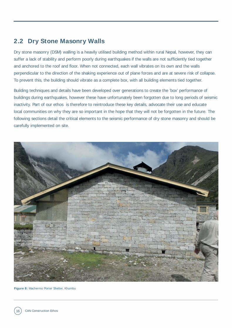
2.2 Dry Stone Masonry Walls
Dry stone masonry (DSM) walling is a heavily utilised building method within rural Nepal, however, they can
suffer a lack of stability and perform poorly during earthquakes if the walls are not suffi ciently tied together
and anchored to the roof and fl oor. When not connected, each wall vibrates on its own and the walls
perpendicular to the direction of the shaking experience out of plane forces and are at severe risk of collapse.
To prevent this, the building should vibrate as a complete box, with all building elements tied together.
Building techniques and details have been developed over generations to create the ‘box’ performance of
buildings during earthquakes, however these have unfortunately been forgotten due to long periods of seismic
inactivity. Part of our ethos is therefore to reintroduce these key details, advocate their use and educate
local communities on why they are so important in the hope that they will not be forgotten in the future. The
following sections detail the critical elements to the seismic performance of dry stone masonry and should be
carefully implemented on site.
Figure 8: Machermo Porter Shelter, Khumbu

www.canepal.org.uk 17
2.2.1 Wall Thickness
The thickness of dry stone masonry walls is critical to their structural stability and performance in an
earthquake. Too thin and they will be unstable and not provide enough insulation; too thick and they will
attract higher seismic forces, put more strain on the building and also be uneconomical.
From best practice standards and experience in the region, walls should be approximately 380mm to 450mm
(15 inches to 18 inches) thick.
2.2.2 Connections
To create the ‘box’ effect of the building, the main structural components of the building (load-bearing walls,
fl oor and roof) should be strongly connected together to ensure they vibrate and move together.
Intersec ons
The intersections of walls (corners and T-junctions) are particularly vulnerable during earthquakes. Unless
there are suffi cient connections, separation of the wall can occur as the walls vibrate independently and
react differently to the forces they experience. When the walls separate they lose their integrity and collapse;
subsequently, the roof will likely also collapse causing a signifi cant risk of fatality. Past earthquakes have
shown that ring beams and through stones at intersections are extremely effective at tying the walls together
(see section 2.2.3). Research has also shown that buildings with ring beams maintain their structural integrity
under higher earthquake forces.
Floor and Roof Connec ons
All load-bearing walls should be anchored to the fl oor and roof at 1800mm (6 feet) centres and within 600mm
(2 feet) from a corner (see section 2.5).

18 CAN Construction Ethos
2.2.3 Ring Beams
Ring beams, or timber bands, have been used in stone masonry construction for centuries. They consist of
a continuous band around the wall of the building located at the plinth, lintel and roof level. In addition to
holding the walls together, ring beams reduce the effective height of the wall thereby reducing its bending
stresses and preventing delamination and risk of collapse. They can also fl ex and move independently without
the structural integrity of the building being compromised. Ring beams are traditionally made of timber, a
natural locally sourced material, which can be collected by the villages at low cost.
Figure 9: Working ring beam, Lapcha
Building in Lapcha, (not constructed by CAN), which survived the 2015 earthquake without suffering catastrophic damage. This can be attributed to the inclusion of ring beams within the design, conveying a tried and tested working example.
Figure 10: Timber ring beams during construction, Bihi Health Post

www.canepal.org.uk 19
Timber
Timber ring beams consist of a pair of parallel timber bands (50mm x 100mm or 2inches x 4inches) aligned
to the inner and outer edges of the wall, connected by perpendicular runners (25mm x 50mm or 1inches x
2inches) at 450mm (18inches) centres.
Corners should be strengthened with diagonal bracing the same size as the runners.
It is important that the runners be properly nailed into the bands to ensure they are connected and work
together. The studs forming the bands should also be properly spliced and nailed together to ensure continuity
of the band and prevent the band pulling apart under seismic loads.
The ring beam at plinth level should be constructed at least 300mm (1 foot) above ground level.
<450mm (18inches) <450mm
(18inches)
<450mm (18inches)
300mm / 1foot 300mm / 1 foot
Figure 11: Timber ring beam splicing detail
<450mm (18inches)
Corner bracing
Parallel bands
Figure 12: Timber ring beam corner detail Figure 13: Timber ring beam intersection detail

20 CAN Construction Ethos
Concrete
A reinforced concrete ring beam is one continuous band, with a width equal to that of the wall. If the concrete
is properly mixed, placed and compacted, a reinforced concrete ring beam has a longer life span than
timber and has connects better with the stone. The depth of the RC band is dependent on the number of
reinforcement bars that are included (two bars 75mm, four bars 150mm); this is dependent on the distance
between crosswalls and the intended level of earthquake shaking. Reinforcement bars must be linked every
150mm and be well bent at corners with 400mm hooks.
Figure 14: Concrete ring beams
2.2.4 Through Stones
One of the main causes of collapse in stone masonry walls is delamination (two layers of the wall peel
apart and collapse outward). Delamination can be prevented by incorporating long stones extending the full
thickness of the wall (‘through-stones’) to tie the wall together and prevent collapse.
Through stones should be included in all dry stone masonry construction at the locations indicated on the
fi gures below. To be effective, through stones should be included every 1200mm (4 feet) horizontally, and
600mm (2 feet) vertically.

www.canepal.org.uk 21
Figure 15: Through stone
Real life representation of a through stone being used in a CAN project at Prok Health Post. A relatively simple adjustment to the dry stone wall offers signifi cant structural benefi ts to the building.
Figure 16: Wall delamination, Machermo Porter Shelter,
Khumbu
Traditional Nepalese building (Machermo Health Post), constructed using no through stones within the wall structure. The building was damaged in the 2015 earthquake providing a classic example of delamination. It can clearly be seen where the outer wall has ‘peeled away’ from the inner wall, resulting in collapse and compromising the building’s structure.
Figure 17: Through stone intersection detail Figure 18: Through stone corner detail
< 1200mm / 4 feet < 1200mm / 4 feet
< 600m
m / 2 feet Through stones

22 CAN Construction Ethos
2.2.5 Stones Above Head Height
Nepalese buildings traditionally include pitched roofs, which result in gable elevations. During an earthquake,
the area of wall in the gable above the eaves height acts as a vertical cantilever, vibrates independently and
collapses unless suffi ciently tied to the roof. Collapse of the gable wall is common during earthquakes. This
creates two signifi cant risks:
• Roof collapse; and
• Major injury or fatality to anyone in the vicinity of the wall from stones falling above head height.
Stones should therefore not be built above the eaves level on gable ends; tin sheets, timber panels or
polycarbonate to be used as substitute at gable ends, ensuring any materials falling from above head height
do not pose a signifi cant threat to life.
Figure 19: Collapsed gable wall Figure 20: Panelling in gable elevation
An example of where a stone constructed gable end has failed during an earthquake; the wall structure has remained intact, however the stone gable has not been tied to the roof and therefore collapsed. This demonstrates the importance of replacing these sections with lightweight materials.

www.canepal.org.uk 23
2.2.6 Internal Wood Panels
One of the main causes of death in the 2015 earthquake was stone masonry walls collapsing inwards and onto
the buildings’ occupants. To reduce this risk, a wooden box structure should be formed on the internal face of
the dry stone wall to redirect the collapsing wall outwards. The box should be formed of minimum 2inch thick
timber planks; thinner timber panels will not support the weight of the collapsing stone and should therefore
not be used.
Figure 21: Internal timber lining forcing stone masonry collapse to outside Figure 22: Timber lining ‘catching’ collapsed stone, Machermo
DSM Walls Summary• Walls should be approximately 380mm to 450mm (15 inches to 18 inches) thick.
• Timber or reinforced concrete ring beams MUST be included in the construc on at plinth, lintel and roof level and must be suffi ciently spliced and connected by runners at 450mm (18 inch) centres;
• Through stones must be included every 1200mm (4 feet) horizontally, and 600mm (2 feet) ver -cally to prevent delamina on and wall collapse;
• No stones should be included in the gable end above eaves height; and
• Rooms must be lined internally with minimum 2inch thick mber planks.

24 CAN Construction Ethos
2.3 Building Confi guration
2.3.1 Floor Plan
The building as a whole or its various blocks should be kept symmetrical where possible as asymmetry
leads to torsion during an earthquake and signifi cantly increases the risks of collapse. A simple rectangular
shape should be used for the buildings as regular shapes have been shown to perform substantially better
during earthquakes. However, long narrow rectangular blocks are particularly vulnerable in the event of an
earthquake. It is therefore desirable to restrict the length of a block to no longer than three times its width
(Figure 23). In some instances, where a larger building is required, the building should be split into smaller
more manageable rectangular blocks, with adequate separation in-between. Although this confi guration is
far from ideal, particularly when the rooms will be used in conjunction with one another daily, it is necessary
to ensure the building maintains its structural stability in the event of future quakes. Figure 24 illustrates how
larger buildings would be split up into separate blocks.
When a building is split into separate blocks, a minimum gap of 3cm should be allowed to ensure the
individual blocks do not collide during the effects of seismic activity. The separation should be treated just
like an expansion joint and may be fi lled/ covered with a weak material that will crush or crumble during an
earthquake so each block can still perform independently. In longer buildings, for additional strength it is also
advisable to separately enclose rooms with a wall rather than having one large, long room (longer than three
times its depth).
< 3X
X
> X/8 < X
/4X
< 3X
Figure 23: Building length to breadth ratio
Figure 24: Building shape confi gurations

www.canepal.org.uk 25
2.3.2 Height
The height of a building has a detrimental effect on its stability during an earthquake. Research determines
that the maximum height of stone masonry walls be 3.5m with cement mortar (2.7m with mud mortar). We do
not advocate the construction of two storey buildings and encourage the construction of two separate single
storey buildings (separated as per section 2.3.1).
We do, however, recognise that there are sites where this is not feasible and the availability of land can
infl uence the decision. In such cases, we encourage taking necessary precautions to mitigate risk. Where two
storeys are required, we will propose timber frame and cladding for the upper storey of the building to reduce
the risk of injury or fatality.
Figure 25: Two storey building, Chhokangpara, Tsum Valley
The entire second storey of this home in Tsum Valley is constructed from timber. This requires a substantial increase in workmanship and quality in the carpentry; competent and skilled wood workers are therefore a necessary asset in order to ensure the building is completed to a suitable standard. Fire safety precautions may also need to be determined due to the additional volume of such a fl ammable material.

26 CAN Construction Ethos
2.3.3 Openings
Openings within a wall weaken its overall strength and so careful consideration of the size and location of
windows and doors is required. Very large windows should generally be avoided, and openings on opposite
walls should be of a similar size to ensure parallel walls have an equal strength (parallel walls of varying
strength create the risk of building torsion). The following guidelines should therefore be followed:
Loca on
It is critical that the intersection of walls (corners and T junctions) are strong to prevent collapse (see section
2.2.2). Openings should therefore be located as close to the centre of a wall as possible, and the minimum
distance from the corner or intersection (B4) should be 600mm (2 feet) or more than 25% of the wall height
(H1), whichever is greater.
Size
To avoid the building ‘twisting’ under an earthquake, parallel walls should be of equal strength. As openings
weaken the strength of a wall, the sizes and position of doors should be equal. The overall width of openings
in a wall should not be greater than 1/3 of the length of the wall (B1+B2+B3 < 0.3L1; B5+B6 < 0.3L2).
B1
B3
B1
B3
Parallel openings of similar size and location
B1
B4
B2
B3 B4 B4
B3 B5 B6
L1 L2
B4 B4 B4H1
Figure 26: Location of openings
Figure 27: Size of openings

www.canepal.org.uk 27
Building Confi gura on Summary • Floor plans should simple and symmetrical;
• The length of a building should be less than three mes its depth;
• L or U shaped buildings should be split into blocks;
• Single storey construc on should always be priori sed unless site constraints preclude it; and
• Large openings in walls should avoided and openings in parallel walls should be of a similar size and loca on.

28 CAN Construction Ethos
2.4 Foundations
Foundations are the substructure from which the building gains its strength and is therefore a crucial
component in the building’s stability and seismic-resilience. Minimum standards are recommended in order to
ensure the building sits upon a suitable platform and so the following guidance should be carefully followed.
2.4.1 Ground Conditions
The proposed site should have a consistent soil type throughout, and if this is not possible, a foundation of
variable width or depth should be constructed. If the foundations are designed to the same standards all the
way around, it will not provide a suffi cient platform for the building and differential settlement will occur. The
foundations need to take into consideration the soil composition below and account for the conditions.
Dimensions
For a wall thickness of 450mm (1 foot 6inches), the foundations should be approximately 750mm wide (3
feet 6inches). If the wall thickness is less than 450mm then the foundation width may be reduced but should
not be less than 600mm (2 feet). A 600mm minimum depth is suggested for foundations on a hard, stiff soil;
however where there is a soft or clay soil area should be a minimum of 1.8m in order to provide suffi cient
strength.
Figure 29: Excavations for foundations to bedrock

www.canepal.org.uk 29
2.4.2 Retaining Walls
Retaining walls should be started 900mm (3 feet) below the soil. The base should be at least half as wide as
the wall height, which should not be more than 2400mm (8feet). The wall should be angled into the slope at
1:5 (15degrees) with the stones at 90degrees to the angle of the wall. Through stones should be included in
the retaining at 600mm (2feet) intervals along the height and length of the wall.
Retaining walls should also be ‘caged’ with wire to prevent stones falling down hill and damaging the building
should the wall delaminate.
Buildings should not be built next to retaining walls; the minimum distance from retaining walls either above or
below the building should be equal to the height of the retaining wall.
H1
H1H1
15 (1:5)
90
Max
240
0mm
(8fe
et)
900m
m(3
feet
)
Figure 30: Retaining wall positions

30 CAN Construction Ethos
Figure 31: Lihi Health Post, North Gorkha
Figure 32: Melamchi Health Post, Helambu
This building has been constructed too close to the retaining wall. The retaining wall is also not

www.canepal.org.uk 31
2.5 Floor and Roof Construction
Roof structures in traditional stone masonry construction are typically formed of timber trusses with
lightweight sheet cladding. The rigidity provided by the roof and fl oor diaphragm, in combination with strong
wall connections, completes the ‘box’ action of the building. The connections of the fl oor and roof to the walls
are critically important to the stability of the walls to prevent them vibrating individually and separating (out-of-
plane collapse).
Unfortunately, traditional construction in remote villages typically gives little consideration to the contribution
the roof can make to the seismic performance of the building. Even in cases where we have provided clear
details, they are not always followed by the local builders. This is largely down to not understanding the
substantial role the roof plays in the overall structural stability of the building.
Traditional roof construction in remote regions will consist of a series of central posts with chords/rafters
positioned and connected between the post and the top of the external wall. This method does not help
tie the walls together; the structure is weak and not suffi ciently connected to form a rigid diaphragm. The
following elements should be included in the roof construction to improve the seismic performance:
• Trusses should have diagonal bracing to give the truss suffi cient stability as shown in fi gure 33;
• Cross bracing on the roof plane should be included to prevent the trusses spreading; and
• Rafters should be connected to a roof band with galvanised wire (timber construction) at 1800mm (6feet)
centres; and
• Floor joists should be securely anchored to the plinth ring beam with 3mm galvanised wire.
600m
m
(3fe
et)
External ground level
Floor joistPlinth ring beam
Foundations
King postRafter
Purlins
Brace
Figure 33: Roof ‘King’ truss Figure 34: Floor beam connection

32 CAN Construction Ethos
2.6 Repair and Retrofi tting
Repair of buildings damaged by an earthquake requires careful consideration as it is diffi cult to return the
building back to its original structural strength for it to be able to withstand future shocks. Structural cracks
are often ‘patched up’ and do not address the structural defi ciencies the building now has; however, as the
cracks have been visually removed, the occupants then have a false sense of security that the building is safe.
Repair to buildings fall into three categories:
• Repair of architectural (i.e. non-structural) elements;
• Structural repair; and/or
• Retrofi tting (introducing seismic-resilient details).
The primary consideration in the assessment of the reparability of the building is the ability to return,
or improve, its structural integrity to withstand future earthquakes. The extent of the works can vary
substantially and the assessment should be carried out by a suitably qualifi ed and experienced professional
and signed off by a CAN engineer. Seismic repair or retrofi t may require works to the individual elements of
the building, but these should contribute to its overall performance in an earthquake (i.e. contributing to the
‘box effect’).
Points to be considered in the assessment will include:
• Level of damage to load bearing walls and feasibility of increasing their lateral strength;
• Can sources of weakness be eliminated (excessively large openings, asymmetrical plan, etc)?
• Cost and availability of funding - repair shouldn’t be considered when the cost exceeds the cost of
demolition and rebuild;
• Site conditions; and
• Availability of materials and skills.

www.canepal.org.uk 33
2.7 Reinforced Concrete
2.7.1 CAN Ethos
CAN does not advocate or promote the use of structural Reinforced Concrete (RC) on the majority of our
projects. The below key reasons explain this ethos:
• The majority of our project sites are in remote and challenging locations with no or limited road access.
This makes the delivery of materials and equipment a logistical and often expensive prospect;
• The materials and skillsets required to build in RC are not native or found in our project locations. This
requires importing both the materials and skills, and in turn does not benefi t the local village economy.
This can isolate existing local skills and trades, mostly made up of skilled carpenters and stones masons;
• It is very diffi cult to provide quality assurance during the construction phase using RC. There are limited
or no facilities to provide cube tests, slump tests and other quality measures for the concrete. In most
locations, the concrete will be mixed by hand in small quantities and cast into large beam and column
shuttering. This provides an inconsistent and often under-strength structural element, and there is no
reassurance and measurement to know the fi nal strength of the building or structure;
Figure 35: Abandoned damaged concrete structure

34 CAN Construction Ethos
• A damaged RC structure requires signifi cant equipment and/or manpower to demolish and remove
the material safely, which is often not available within the remote mountain villages. This leads to
abandoned structures with the only means of removal being through donor involvement or funding,
thereby contributing to donor dependency;
• The use of RC does not match the vernacular and traditional building methods of the remote regions of
the Himalayas. Introducing large quantities of concrete increases the risk that traditional carpentry and
stone masonry skills are lost in the long term, and that the heritage of the villages and communities
may be eroded and lost over time. This can damage the character of the villages and potentially harm
the tourist (trekking) industry upon which many communities are heavily reliant in order to build a
sustainable local economy.
The above list is not exhaustive but provides clear guidance and justifi cation of our advocacy for local building
materials and employment of local building expertise.
Figure 36: Concrete buildings

www.canepal.org.uk 35
2.7.2 Quality Assurance
We recognise that in certain locations, and depending on Government and Local Authority recommendations,
that Reinforced Concrete can be the most cost effective and pragmatic solution. In these instances,
we advocate that clear and robust Quality Assurance processes are in place and adhered to. In such
circumstances we recommend the following Quality Assurance measures are put in place:
• An appropriate, site specifi c, design is created by a suitably qualifi ed and experienced architect/
engineer, and is approved at the correct Government level of sign off;
• A construction programme is produced and key construction milestones are established;
• An experienced and qualifi ed Construction Project Manager or Overseer (appointed by CAN) is present
throughout construction to ensure quality standards are met and adhered to. They will be responsible
for signing off key milestones;
• A suitably qualifi ed and experienced Contractor is appointed through the correct procurement route
(depending on capital value of the project). The Contractor should have a track record for constructing
similar sized projects in Reinforced Concrete. They should have also delivered projects in similar
locations where they have had to overcome logistical and access issues; and
• The Contractor produces a simple yet clear Quality Management Plan setting out its building
methodology, equipment, storage of materials and quality measures being used. Quality measures
should include cube tests and any other practical quality measures for the structure. This should be
signed off by the Construction Project Manager.
Given the remote locations and challenges of working in Nepal the above should be approached in a pragmatic
and sensible manner.

36 CAN Construction Ethos
2.7.3 Post-earthquake Damage Assessment
We recommend that all projects have a simple and clear damage assessment guide handed over with the
building. In the case of any future disasters, the guide could be used to provide high level guidance for a non-
technical person to carry out an initial damage assessment of the building. In the case of Reinforced Concrete,
it is a safety mechanism to allow the building occupants to know whether they should permanently evacuate
the building before a proper qualifi ed assessment can be carried out. The guide should point out where critical
failures can be identifi ed and, through diagrams, show what structural and non-structural failures look like.
Figure 37: Post-earthquake damage to RC frame building, Bahrabise
Figure 38: Catastrophic failure to RC column, Bahrabise

www.canepal.org.uk 37
ConclusionCommunity Action Nepal’s ethos is distinctly manifested in the way it operates and chooses to undertake
construction works; with an unmistakable passion to maintain the spirit of a culture, era, and community
within the rural Nepalese locations within which it operates. CAN’s ethos can be categorised into a handful
of sections which it applies to each project to ensure the best possible construction with regards to safety,
robustness, culture, reparability and practicality for the locals.
CAN supports the use of local materials and traditional methods wherever possible within its projects to
ensure the locals can build, repair and maintain their own infrastructure; eliminating the endless circle of
donor dependency. The CAN ethos aims to not only construct buildings, but also minimize the risk of fatality
amongst the local community in the event of future quakes by managing residual risks. This can be done by
fi rst identifying the risks and then taking action to minimize them from occurring. An example of this could
be stones falling from above head height, the risk of which can be eliminated by using a lightweight tin sheet
as a substitute. This report contains a detailed breakdown of the preferred construction methods for each
section of the building and a how they link towards achieving CAN’s ethos and good practice guidelines. CAN
uses traditional techniques where possible, however, in some cases they may not be adequate enough to offer
substantial seismic protection or governmental defi ned design may stipulate otherwise. In such instances,
alternative methods are adopted and taught to the locals where feasible.
In essence, each project is treated with unparalleled individuality, making sure every decision made is directly
suited to the individual project as well as meeting the needs of the local residents. This subsequently creates
a building that CAN’s ethos has been moulded to, and not a building that has been moulded around CAN’s
ethos.

38 CAN Construction Ethos
GlossaryBox Effect Effect created when structural elements (fl oors, walls and roof) are strongly connection and the
building vibrates as a monolithic box. Past earthquakes show buildings with box effect perform better and level
of damage is reduced.
Delamination Common failure of stone masonry walls without through stones; exterior wall wythes ‘peel’
apart due to earthquake vibrations leading to partial or total wall collapse.
Diaphragm Floor, ceiling or braced roof structure strongly connected to walls distributing lateral forces to
vertical elements (walls or columns) and contributing to ‘box’ effect.
Dry Stone Masonry Construction method of load bearing walls built with two layers of either irregular or
regular (‘dressed’) stone without mortar.
In-plane Forces Earthquake forces acting along the length of a wall.
Irregular Building Building with asymmetrical confi guration either vertically or horizontally, i.e. a sudden
change in plan or elevation. L-, or U-shaped buildings, buildings with setbacks or missing walls are classed as
irregular. Not desirable in seismically active regions.
Lateral Loads Loads acting in a horizontal direction.
Liquefaction Earthquake induced phenomenon occuring when loose, granular soils become saturated, lose
their strength and behave as a liquid.
Out-of-plane Load Seismic load acting at a right angle to the wall surface
Out-of-plane Collapse Wall collapse as a result of out-of-plane or lateral loads. Walls are weaker under out-
of-plane loads and are more prone to collapse.
RC Reinforced Concrete
Ring beam Horizontal band made of timber or concrete located at plinth lintel and roof. Reduce effective wall
height and tie the walls together to create ‘box’ effect.
Through Stones Long stones connecting two wall wythes together to prevent delamination.
Wythe Stone masonry walls usually contain two exterior wythes built of large stone boulders. Each vertical
leaf (layer) is a wythe.

www.canepal.org.uk 39
BiblographyGovernment of Nepal; Centre of Resilient Development; MRB Associates (2016). Seismic Retrofi tting Guidelines of Buildings in Nepal
Engineering, I. A. (2004). General Concepts of Earthquake Resistant Design. Guidelines for Earthquake Resistant Non-Engineered Construction, 66–69.
Government of Nepal, Department of Urban Development and Building Construction (1994). Nepal National Building Code. Guidelines for Earthquake Resistant Building Construction: Low Strength Masonry
Jitendra Bothara, S. B. (2011). Improving the Seismic Performance of Stone Masonry Buildings. Oakland: Earthquake Engineering Research Institute.
Pearson, W & Utting, G. (2016). Milarepa - Health Post. CAN - Post Earthquake Reconstruction Report, 30–32
Scott, D. (2016). Community Action Nepal: One Year on Progress Report.
List of FiguresFigure 1: Circle of Dependency 5
Figure 2: High Risk of Landslide, Milareppa, Helambu 6
Figure 3: Local stonemasons 8
Figure 4: Seismically-resilient traditional construction techniques 9
Figure 5: Site visits and professional oversight, Shree Himalayan Primary School, Helambu 10
Figure 6: Community Engagement, Lihi, North Gorkha 12
Figure 7: Building adjacent to steep slope, Lihi Health Post, Nubri Valley 13
Figure 8: Machermo Porter Shelter, Khumbu 16
Figure 9: Working ring beam, Lapcha 18
Figure 10: Timber ring beams during construction, Bihi Health Post 18
Figure 11: Timber ring beam splicing detail 19
Figure 12: Timber ring beam corner detail 19
Figure 13: Timber ring beam intersection detail 19
Figure 14: Concrete ring beams 20
Figure 15: Through stone 21
Figure 16: Wall delamination, Machermo Porter Shelter, Khumbu 21
Figure 17: Through stone intersection detail 21
Figure 18: Through stone corner detail 21
Figure 19: Collapsed gable wall 22
Figure 20: Panelling in gable elevation 22
Figure 21: Internal timber lining forcing stone masonry collapse to outside 23
Figure 22: Timber lining ‘catching’ collapsed stone, Machermo 23
Figure 23: Building length to breadth ratio 24
Figure 24: Building shape confi gurations 24
Figure 25: Two storey building, Chhokangpara, Tsum Valley 25
Figure 27: Size of openings 26
Figure 26: Location of openings 26
Figure 29: Excavations for foundations to bedrock 28
Figure 30: Retaining wall positions 29
Figure 31: Lihi Health Post, North Gorkha 30
Figure 32: Melamchi Health Post, Helambu 30
Figure 33: Roof ‘King’ truss 31
Figure 34: Floor beam connection 31
Figure 35: Abandoned damaged concrete structure 33
Figure 36: Concrete buildings 34
Figure 37: Post-earthquake damage to RC frame building, Bahrabise 36
Figure 38: Catastrophic failure to RC column, Bahrabise 36

WYG
Arndale Court
Headingley, Leeds
LS6 2UJ
T: +44 (0)113 278 7111
www.wyg.com
If you would like any more
information please contact:
Community Action Nepal
Stewart Hill Cottage
Hesket Newmarket
Wigton, Cumbria
CA7 8HX
T (Offi ce): +44 (0)17684 84842
www.canepal.org.uk
Registered Charity No. 1067772