communication / function manual en - · pdf filecommunication / function manual ... 5...
TRANSCRIPT

WE CREATE MOTION
EN
Communication / Function Manual
Motion Control
Series MCBL 300x COSeries MCDC 300x COSeries 3564...B COSeries 32xx...BX4 COSeries 22xx...BX4 COD

2
Imprint
Version:2nd edition, 17.12.2013
Copyrightby Dr. Fritz Faulhaber GmbH & Co. KGDaimlerstr. 23 / 25 · 71101 Schönaich
All rights reserved, including those to the translation.No part of this description may be duplicated, repro-duced, stored in an information system or processed or transferred in any other form without prior express writ-ten permission of Dr. Fritz Faulhaber GmbH & Co. KG.
This technical manual has been prepared with care.Dr. Fritz Faulhaber GmbH & Co. KG cannot accept any liability for any errors in this technical manual or for the consequences of such errors. Equally, no liability can be accepted for direct or consequential damages resulting from improper use of the equipment.
The relevant regulations regarding safety engineering and interference suppression as well as the requirements specified in this technical manual are to be noted and fol-lowed when using the software.
Subject to change without notice.
The respective current version of this technical manual is available on FAULHABER‘s internet site:www.faulhaber.com

3
Guide to the document
Notes on the initial start-up of a FAULHABER Motion Control system at the PC in the default configuration
Quick Start Page 8
Specification of the CANopen communication protocol
CANopen protocol description Page 16
Overview of the supported drive profiles according to CiA 402
Functional description Page 36
Detailed description of the parameters for the implemented Function blocks within the drive
Commissioning Page 73
Description of all the drive's parameters and commands, broken down into functional areas
Parameter description Page 84
Overview
Overview of the FAULHABER Motion Control Drives documents
Document Contents
Technical Manual Device installation, safety, specification
Communication and function manual (CANopen FAULHABER)Communication and function manual (CANopen CiA)Communication and function manual (RS232)
Initial start-up, function overview, protocol description and parameter description.
Motion Manager instruction manual Operation of the "FAULHABER Motion Manager" PC software for configuration and commissioning
Product data sheets Technical limit and operating data

4
Table of Contents
1 Important Information 61.1 Symbols used in this manual 6
1.2 Additional information 7
2 Quick Start 82.1 Start with unconfigured controller 8
2.2 Set node number and baud rate 9
2.3 Operation using FAULHABER Motion Manager 10
2.3.1 Configuring the drives 10
2.3.2 Activate CANopen nodes 10
2.3.3 Operation in one of the CANopen CiA 402 drive profiles 11
2.4 Operation using own host application 14
2.4.1 Activate CANopen nodes 14
2.4.2 Configuring the drives 14
2.4.3 Operation in one of the CANopen CiA 402 drive profiles 15
3 CANopen protocol description 163.1 Introduction 16
3.2 PDOs (process data objects) 19
3.3 SDO (service data object) 21
3.4 Emergency object (error message) 23
3.5 SYNC Object 25
3.6 NMT (network management) 26
3.7 Entries in the object dictionary 30
4 Functional description 364.1 Device control 37
4.1.1 State machine of the drive 37
4.1.2 Selection of the operating mode 41
4.2 Factor group 42
4.3 Profile position mode and position control function 45
4.4 Homing mode 50
4.5 Profile velocity mode 54
4.6 Drive data 57
4.7 Inputs / outputs 58
4.7.1 Limit switch connections and switching level 58
4.7.2 Special functions of the fault pin 60
4.7.3 Query the input states 62
4.8 Error handling 63
4.8.1 Query of the device state 64

5
Table of Contents
4.9 Technical information 65
4.9.1 Ramp generator 65
4.9.2 Sinus commutation 68
4.9.3 Current controller and I²t current limitation 68
4.9.4 Overtemperature protection 70
4.9.5 Under-voltage monitoring 70
4.9.6 Overvoltage regulation 70
4.9.7 Setting the controller parameters for velocity and position controller 70
5 Commissioning 735.1 Node number and baud rate 73
5.2 Basic settings 75
5.3 Configuration using the Motion Manager 76
5.3.1 Connection setting 77
5.3.2 Motor selection 78
5.3.3 Drive configuration 78
5.4 Data set management 83
5.5 Diagnosis 83
5.5.1 Status display 83
5.5.2 Trace function 83
6 Parameter description 846.1 Communication objects according to CiA 301 84
6.2 Manufacturer-specific objects 90
6.3 Drive profile objects according to CiA 402 96

6
1 Important Information
1.1 Symbols used in this manual
WARNING! Warning!This pictogram with the wording "Warning!" indicates an imminent danger which can result in physical injuries.
f This arrow points out the appropriate action to take to prevent the imminent danger.
CAUTION! Caution!This pictogram with the wording "Caution!" indicates an imminent danger which can result in slight physical injuries or material damage.
f This arrow points out the appropriate precautions.
REGULATION! Regulations, guidelines and directivesThis pictogram with the wording "Regulation" indicates a statutory regulation, guideline or directive which must be observed in the respective context of the text.
NOTE NoteThis "Note" pictogram provides tips and recommendations for use and handling of the component.

7
1 Important Information
1.2 Additional information
WARNING! Risk of injuriesFailure to comply with the safety instructions during installation and operation can result in irrepara-ble damage to the device and a risk of injuries to the operating personnel.
f Please read through the whole of your drive's technical manual before installing the drive.
f Keep this communication and function manual in a safe place for subsequent use.
NOTE Always use the current version of the FAULHABER Motion Manager.
The respective current version is available to download from www.faulhaber.com/MotionManager.
Motion Manager 5 or higher is required to operate and configure this device family!
NOTE The information given in this instruction manual refers to the standard version of the drives.
Please refer to any additional information sheet provided in the event of differences in information due to a customer-specific motor modification.
NOTE Motion Controllers with a CANopen interface are designed as slaves in a CANopen environment and always require a connection with a CANopen Master to operate.

8
2 Quick Start
2.1 Start with unconfigured controller
In the unconfigured state node number 255 is set as the default in the Motion Control systems and automatic detection of the baud rate is active.
The start of an unconfigured FAULHABER Motion Controller or a Motion Control system with CAN-open interface is divided into 4 steps.
Step 1: Set node number and baud rate by means of LSS
The correct node number and baud rate is set via the LSS service according to CiA 305. You can use the FAULHABER Motion Manager or another CANopen configuration tool for this. You can then set up communication to the drive node immediately; it appears with the correct name in the Motion Manager’s tree view.
Step 2: Set motor and controller data via the Motor Wizard
Set the right motor for the Motion Controller. This preconfigures the controllers for the set motor and the corresponding load.
Step 3: Set application parameters using the Configuration Wizard
Use the configuration dialog to adjust at least the basic settings such as operating mode, range lim-its, etc. to your application and to optimise the Hall sensor signals of external BL controllers.
Step 4: Operating the drive via the Tuning Wizard
If you are operating the motor for the first time, use the Tuning Wizard to adjust it. Here you can adjust the controller amplifications precisely to your application.
Step 5: Further settings
If necessary, you can also use the Configuration Wizard to make further application-specific settings. Alternatively, you can also start up the drive directly at your control.
To facilitate introduction, this chapter highlights the initial steps for commissioning and operation of FAULHABER Motion Controllers with CANopen interface. However, the detailed documentation must always be read and taken into account, particularly Chapter 5.2 “Basic settings”!

9
2 Quick Start
2.2 Set node number and baud rate
The standard units are delivered without valid node address (node ID = 0xFF) and with automatic baud rate detection set.
In order to set the baud rate and node address, the unit must first be connected via CAN to an ap-propriate configuration tool, which supports the LSS protocol (layer setting services and protocol) according to CiA DSP305.
NOTE FAULHABER Motion Manager installed on a PC with supported CAN interface can also be used for this. The LSS compatible configuration tool can be used to set the node address and baud rate, either in Global mode, if only one drive is connected, or in Selective mode via the serial number, if a drive is to be configured in the network (see Chapter 5.1 “Node number and baud rate”).
If the FAULHABER Motion Manager is to be used as the configuration tool, proceed as follows:
The following steps are necessary for commissioning using the default configuration:
1. Connect the drive unit to a voltage source (24V). For details of connection cable assignment and the operating voltage range of the drive, see Chapter 3 “Installation” in the technical manual.
2. Connect drive unit to the CAN interface of the PC and switch on or connect PC to the CAN net-work.
3. Start FAULHABER Motion Manager.
4. Activate CAN interface as communication interface and configure using the menu item “Terminal – Connections…” or the Connection Wizard.
5. Select menu item “CAN - LSS (DSP305)…”.
6. Select Configuration mode:
a. Globally configure individual drive (LSS Switch Mode Global) if only one LSS node is connected and you do not want to enter any further data.
b. Selectively configure specified nodes (LSS Switch Mode Selective) if a node is to be configured in the network. If the node has not yet been found in the Node Explorer, enter the serial num-ber of the drive node to be configured here, otherwise the data fields are already correctly preset.
7. In the next dialog, select the required transfer rate or “Auto” and enter the required node num-ber.
8. Press “Send” button.
9. The settings are transferred and are permanently stored in the controller. The Motion Manager then calls up the Scan function again and the node should now be displayed with the correct node number in th e Node Explorer. After switching off and on again, the drive will operate with the set configuration.
10
2 Quick Start
2.3 Operation using FAULHABER Motion Manager
The FAULHABER Motion Manager provides easy access to the CANopen state machine using menu entries, which can be opened either with the node explorer’s context menu (right-click) or with the “CAN” menu. The required node must have been activated beforehand by double clicking in the node explorer. The current statuses are always displayed in the status line at the bottom edge of the Motion Manager window.
Further information on the state machine of a CANopen node is given in Chapter 3 “CANopen proto-col description”.
NOTE For simplified use, the Motion Manager also provides special commands for the CO variants. Those can be entered directly in the command input line or selected from the Commands menu. After sending the command, a command interpreter is activated which converts the command into a cor-responding CAN message frame.
2.3.1 Configuring the drives
CAUTION! Check basic settingsIncorrect values in the Motion Controller's settings can result in damage to the controller and / or drive.
Motion Control systems with electronics built-onto the motor are already preset in the factory. Mo-tion controllers with a connected motor must be equipped with current limitation values suitable for the motor and suitable controller parameters before being started up. In Motion Manager the motor wizard is available for selection of the motor and corresponding suitable basic parameters.
Other settings, e.g. for the function of the fault output, can be made under the “configuration – drive functions” menu item, where a convenient dialog is provided (see Chapter 5.3 “Configuration using the Motion Manager”). The configuration dialog is also available for direct access in the wizard bar of the Motion Manager (configuration wizard).
2.3.2 Activate CANopen nodes
In order to drive a motor using the Motion Manager, follow the procedure below (assuming a valid node number and matching baud rate are set):
Start network nodes.
Select the “CANopen Network Management (NMT) – Start Remote Node” entry in the node explor-er’s context menu or in the “CAN” menu.
The state of the node is then “operational”, PDO communication is now available!

11
2 Quick Start2.3 Operation using FAULHABER Motion Manager
2.3.3 Operation in one of the CANopen CiA 402 drive profiles
Activate drive using the CiA 402 state machine:
A CiA 402 drive must be activated according to a fixed sequence of steps. The necessary commands are directly available in the context menu of the drive node:
� Shutdown
Select “Device Control (DSP402) – Shutdown” entry using the context menu in node explorer or using the “CAN” menu.
� Switch On
Select the “Device Control (DSP402) – Switch on” entry using the context menu in node explorer or using the “CAN” menu.
� Enable Operation
Select the “Device Control (DSP402) - Enable Operation” entry using the context menu in node explorer or using the “CAN” menu.
Alternatively, you can also simply press the green “Switch on output stage” button or F5, in order to carry out these steps all at once.
Drive motor (examples):
1. Drive motor with 100 rpm velocity control:
Set profile velocity mode:
� Select the “Motion Control (DSP402) - modes_of_operation (6060h)” entry in the node ex-plorer’s context menu or in the “CAN” menu.
� Enter value 3 for the “profile velocity mode” in the dialogue box the necessary command is entered directly in the command field of the Motion Manager.
� Press “Send” button next to the command field.

12
2 Quick Start2.3 Operation using FAULHABER Motion Manager
Set target velocity to value 100:
� Select the “Motion Control (DSP402) - target_velocity (60FFh)” entry using the context menu of the node explorer or using the “CAN” menu.
� Enter value 100 for the target velocity in the dialogue box the necessary command is en-tered directly in the command field of the Motion Manager.
� Press “Send” button next to the command field.
Stop motor:
� Set target velocity to value 0 (object 0x60FF) or
� Select “Disable Operation” from the toolbar.

13
2 Quick Start2.3 Operation using FAULHABER Motion Manager
2. Move motor relatively by 10 000 increments:
Set profile position mode:
� Select the “Motion Control (DSP402) - modes_of_operation (6060h)” entry in the node ex-plorer’s context menu or in the “CAN” menu.
� Enter value 1 for the “Profile Position Mode” in the dialogue box the necessary command is entered directly in the command field of the Motion Manager.
� Press “Send” button next to the command field.
Set target position to value 10 000:
� Select the “Motion Control (DSP402) - target_position (607Ah)” entry in the node explorer’s context menu or in the “CAN” menu.
� Enter value 10 000 for the target position in the dialogue box the necessary command is entered directly in the command field of the Motion Manager.
� Press “Send” button next to the command field.
Move to target position: Set “New set-point” and “rel” in controlword.
� Select the “Motion Control (DSP402) - new_setpoint_rel” entry in the node explorer’s context menu or in the “CAN” menu.

14
2 Quick Start
2.4 Operation using own host application
2.4.1 Activate CANopen nodes
The broadcast command “Start Remote Node” with CAN ID 0 is used to start either an individual node or the whole network and to set it to “operational“ status:
11 bit identifier 2 bytes user dataID 0x000 01 00
The first data byte contains the start command “Start Remote Node”, the second data byte contains the node address or 0 for the whole network.
All functions can be proceeded after the node has been started. The drive can now be activated and operated using the device control functions according to CiA DSP402.
The identifiers of the individual objects are preset according to the predefined connection set and depend on the node number (see Chapter 3.6 “NMT (network management)”):
Object CAN ID DescriptionTxPDO1 0x180 + Node ID Receive drive data (e.g. status values)RxPDO1 0x200 + Node ID Send data to the drives (e.g. control commands)TxPDO2 0x280 + Node ID Receive drive data (e.g. status values)RxPDO2 0x300 + Node ID Send data to the drives (e.g. control commands)TxPDO3 0x380 + Node ID Receive drive data (e.g. status values)RxPDO3 0x400 + Node ID Send data to the drives (e.g. control commands)TxPDO4 0x480 + Node ID Receive drive data (e.g. status values)RxPDO4 0x500 + Node ID Send data to the drives (e.g. control commands)TxSDO1 0x580 + Node ID Read entry of the object dictionaryRxSDO1 0x600 + Node ID Write entry of the object dictionary
In delivery status, after they are switched on, the drives are in operating mode modes of operation = 1 (profile position mode). The drive is controlled by using the device control state machine, which is operating using the controlword (object 0x6040 or RxPDO) and is queried using the statusword (object 0x6041 or TxPDO).
2.4.2 Configuring the drives
The drive can be configured by means of SDO transfer using the objects of the object dictionary.
NOTE Use of the FAULHABER Motion Manager is recommended for the basic settings (see Chapter 5.2 “Basic settings”).

15
2 Quick Start2.4 Operation using own host application
2.4.3 Operation in one of the CANopen CiA 402 drive profiles
A CiA 402 drive must be activated according to a fixed sequence of steps (see Chapter 4.1 “Device control”). Write access to the controlword is possible using the object dictionary at address 0x6040 or using RxPDO:
1. Shutdown:
Controlword = 0x00 06
2. Switch on:
Controlword = 0x00 07
The drive is then in “Switched On” status. Operation must then be released to enable drive com-mands to be executed.
3. Enable operation:
Controlword = 0x00 0F
The drive is then in “operation enabled” status, in which it can be operated using the corre-sponding objects of the adjusted control mode (see Chapter 4.1 “Device control” and Chapter 4.2 “Factor group”).
4. Drive motor (examples):
Drive motor with 500 rpm velocity control:
Modes of operation (object 0x6060): Set 3 (profile velocity mode) by SDO access.
Target velocity (object 0x60FF): 500
Stop motor:
� Set Target Velocity to value 0 (Object 0x60FF) or
� Controlword = 0x00 07 (Disable Operation).
Move motor relatively by 10 000 increments:
Modes of Operation (Object 0x6060): Set 1 (Profile Position Mode) by means of SDO access.
Target Position (Object 0x607A): 10 000
Controlword = 0x00 7F (New set-point, Change set immediately, rel)

16
3 CANopen protocol description
3.1 Introduction
� CANopen is a standardised software protocol based on the CAN hardware (Controller Area Net-work).
� The international CAN Organisation CAN in Automation e.V. (CiA) defines the communication profile in DS301 (description of the communication structure and methods for parameter access, control and monitoring functions).
� Device profiles are specified for the different devices, such as DSP402 for drives and DS401 for I / O devices (general device description from the view of the user).
� Public data is managed using the object dictionary (parameter table, access to entries via Index and subindex).
� There are two data communication objects:
• PDOs (process data objects for control and monitoring)
• SDOs (service data objects for access to the object dictionary)
� Further objects are available for network management, node monitoring and synchronisation.
� CANopen supports up to 127 nodes per network segment with transmission rates up to 1 Mbit/s.
� The communication is message based, each communication object is assigned its own 11 bit iden-tifier.
Guide
Introduction Page 16
PDOs (process data objects) Page 19
SDO (service data object) Page 21
Emergency object (error message) Page 23
SYNC Object Page 25
NMT (network management) Page 26
Entries in the object dictionary Page 30

17
3 CANopen protocol description3.1 Introduction
FAULHABER Motion Controllers support the CANopen communication profile in accordance with CiA DS301 V4 and the device profile for drives and Motion Control in accordance with CiA DSP402 V3; these support the following communication objects:
� 4 transmit PDOs
� 4 receive PDOs
� 1 server SDO
� 1 emergency object
� NMT with node guarding and heartbeat
� 1 SYNC object
The identifier configuration of the CANopen objects is preset according to the “predefined con-nection set” (see Chapter 3.6 “NMT (network management)”). The data assignment of the PDOs is preset according to the “PDO set for servo drive” according to CiA DSP402 V3 and can be changed by the user (dynamic PDO mapping).
Many manufacturers offer CANopen libraries for PC and PCS systems, via which the individual objects can be conveniently accessed, without having to worry about the internal structure.
The FAULHABER Motion Manager also enables easy access to the individual objects via a graphic user interface.
Motor
CAN
CA
N n
od
e
Ob
ject
Dic
tio
nar
yEr
ror
Han
dlin
g
n*, Pos*Motor Control
Control Word
Status Word
n, Pos
EMCY
PDO1 … DPO4
SDO
CiA 402 Drive State MachineCiA 301 CANopen State Machine
NMTGuarding
A Faulhaber Motion Controller addressed via CANopen is, like all CANopen devices, separated into the communication part and the actual controller. In the communication part the communication services are implemented according to CiA 301, the drive itself is implemented according to the CAN-open device profile 402. The drive’s parameters are accessed via the CANopen object dictionary.

18
3 CANopen protocol description3.1 Introduction
The tasks of the communication services are first described here briefly. A detailed description is given in sections 3.1 to 3.6.
Network management: NMT
For each CANopen node, communication is activated via the network management of the CANopen Master and can therefore also be monitored for its current state.
Parameter storage in the object dictionary
All the drive’s parameters, as well as the setpoint and actual values, can be addressed in the object dictionary under an index number (0x1000 – 0x6FFF) and a subindex (0x00 – 0xFF). A differentiation is made between simple parameters, such as setpoint value, and structured parameters such as the parameters of the velocity controller.
All CANopen accesses to the controller are made via the object dictionary.
Access to all parameters: SDO
The CANopen Master can access the parameters of the CANopen node via the Service Data Object. To this end, with each SDO access, precisely one parameter is read, or if possible is also written. With each SDO access, precisely one node can be addressed in the network; write accesses are also always confirmed.
Access to realtime data: PDO
The Process Data Objects can be used to access several drive parameters simultaneously via a CAN telegram. This means, for example, that setpoint values can be specified or several actual values can be queried simultaneously.
The parameters to be sent or received in a PDO can be freely configured. As the message IDs of the PDOs can be freely configured this means, for example, that several drive nodes can also receive setpoint values with the same PDO.
To this end, Faulhaber Motion Controllers or CO variant Motion Control systems provide up to 4 PDOs per node and data direction. PDOs are only sent or received if communication is in the “opera-tional” state.
Synchronisation: SYNC object
A Sync telegram can be used to synchronise the different applications at the CAN bus. Setpoint and actual values sent via PDOs are typically synchronised.
Error handling: EMCY
With the EMCY telegram the higher-level control can be informed about errors that have occurred in the drive node, either in the communication or in the actual drive. To this end, the error code is transmitted asynchronously in a CAN message; it is not necessary to continuously query the state.
Control of the drive: CiA 402 state machine
The drive is switched on and if necessary deactivated again via the drive’s state machine. In case of an error the drive can switch to error state.
Transitions to other states are initiated by the high-level control using bits 0 … 3 of the controlword.
The current state is indicated by bits 0 … x of the statusword.
In order for the drive to be operated in one of the modes, it must be in “Operation Enabled” state.

19
3 CANopen protocol description
3.2 PDOs (process data objects)
PDOs correspond to a CAN message frame with up to 8 bytes and are used to transmit process data, i.e. to control and monitor the device’s behaviour. The PDOs are designated from the point of view of the field device. Receive PDOs (RxPDOs) are received by the field device and contain, e.g. control data, send PDOs (TxPDOs) are sent by the field device and contain, e.g. monitoring data.
PDOs can only be transmitted if the device is in “operational” state (see Chapter 3.6 “NMT (network management)”).
PDO communication types:
� Event controlled: Data are automatically sent following a change to the device.
� Remote request (RTR): Data are sent following a request message frame.
� Synchronised: Data are sent following receipt of a SYNC object.
See Chapter 3.5 “SYNC Object” for information on setting the various types of transmission.
FAULHABER Motion Controllers provide the following PDOs in their default configuration: the user can adjust the identifier (COB ID) and data content (PDO mapping) of the PDO to their individual needs. A maximum of 4 parameters can be mapped in a PDO.
RxPDO1: Controlword
11 bit identifier 2 bytes user data0x200 (512d) + Node ID LB HB
Contains the 16 bit controlword according to CiA DSP402, which controls the state machine of the drive unit. The PDO refers to object index 0x6040 in the object dictionary. The bit allocation is de-scribed in Chapter 4.1 “Device control”.
TxPDO1: Statusword
11 bit identifier 2 bytes user data0x180 (384d) + Node ID LB HB
Contains the 16 bit statusword according to CiA DSP402, which displays the state machine of the drive unit. The PDO refers to object index 0x6041 in the object dictionary. The bit allocation is de-scribed in Chapter 4.1 “Device control”.
RxPDO2: Controlword, Target Position (pp)
11 bit identifier 2 to 6 bytes user data0x300 (768d) + Node ID LB HB LLB LHB HLB HHB
Contains the 16-bit controlword and, in Profile Position Mode (pp), the 32-bit value of the target position (Object 0x607A).

20
3 CANopen protocol description3.2 PDOs (process data objects)
TxPDO2: Statusword, Position Actual Value
11 bit identifier 2 to 6 bytes user data0x280 (640d) + Node ID LB HB LLB LHB HLB HHB
Contains the 16-bit statusword and the 32-bit value of the actual position (object 0x6064).
RxPDO3: Controlword, Target Velocity (pv)
11 bit identifier 2 to 6 bytes user data0x400 (1024d) + Node ID LB HB LLB LHB HLB HHB
Contains the 16-bit controlword and in Profile Velocity Mode (pv) the 32-bit value of the target velocity (Object 0x60FF).
TxPDO3: Statusword, Velocity Actual Value
11 bit identifier 2 to 6 byte user data0x380 (896d) + Node ID LB HB LLB LHB HLB HHB
Contains the 16-bit statusword and the 32-bit value of the actual speed (object 0x6064).
RxPDO4: Controlword, Target Position Internal Value (pp)
11 bit identifier 2 bytes user data0x500 (1280d) + Node ID LB HB LLB LHB HLB HHB
Contains the 16-bit controlword and in Profile Position Mode (pp) the 32-bit value of the target posi-tion in internal units (Object 0x357A).
TxPDO4: Position Actual Value, Velocity Actual Value
11 bit identifier 8 bytes user data0x480 (1152d) + Node ID LB HB LLB LHB HLB HHB
Contains the 32-bit value of the actual position (object 0x6064) and the 32-bit value of the actual speed (object 0x606C).
The mapping settings are stored in the communication objects 0x1600 to 0x1603 and 0x1A00 to 0x1A03.
NOTE Changing the data content of individual PDOs requires a CANopen configuration tool, which sup-ports dynamic PDO mapping. The FAULHABER Motion Manager can be used for this task.
If mapping parameters are described without complying with the specified mapping procedure, SDO error 0x06090030 is sent. If, for a number of mapped objects, a larger value is entered than the valid entries that exist in the respective subindices of the mapping parameter objects, SDO error 0x06020000 is sent. If the number of mapped objects is 0, a PDO with length 0 is sent.
NOTE In the default configuration (transmission type 255), TxPDOs, which contain the statusword, are sent automatically if the status of the statusword changes. Alternatively, PDOs can be queried cyclically via SYNC or RTR.

21
3 CANopen protocol description
3.3 SDO (service data object)
The service data object can be used to read and describe parameters in the object dictionary (OD). They are accessed via the 16 bit index and the 8 bit subindex. The Motion Controller functions as a server, i.e. it makes data available (upload) at the request of the client (PC, PCS) (Upload) or receives data from the client (download).
Byte0 Byte1-2 Byte3 Byte4Command Specifier 16 bit index 8 bit subindex 1-4 byte parameter data
Entry in the object dictionary
A differentiation is made between 2 SDO transfer types:
� Expedited transfer: Transfer of 4 bytes maximum
� Segmented transfer: Transfer of more than 4 bytes
As, apart from for query of the version and the device name, only 4 bytes maximum are transferred by the FAULHABER Motion Controllers, only the expedited transfer is described in the following.
The size of the message frames is always 8 bytes and their structure is as follows:
Read OD entries: Client Server, Upload Request
11 bit identifier 8 bytes user data0x600 (1536d) + Node ID 0x40 Index LB Index HB Subindex 0 0 0 0
Server Client, Upload Response
11 bit identifier 8 bytes user data0x580 (1408d) + Node ID 0x4x Index LB Index HB Subindex LLB (D0) LHB (D1) HLB (D2) HHB (D3)
Byte0 (0x4x) gives the number of valid data bytes in D0-D3 and the transfer type and is coded for expedited transfer ( 4 data bytes) as follows:
� 1 data byte in D0: Byte0 = 0x4F
� 2 data bytes in D0-D1: Byte0 = 0x4B
� 3 data bytes in D0-D2: Byte0 = 0x47
� 4 data bytes in D0-D3: Byte0 = 0x43
Write OD entries: Client Server, Download Request
11 bit identifier 8 bytes user data0x600 (1536d) + Node ID 0x2x Index LB Index HB Subindex LLB (D0) LHB (D1) HLB (D2) HHB (D3)
Byte0 (0x2x) gives the number of valid data bytes in D0-D3 and the transfer type and is coded for expedited transfer ( 4 data bytes) as follows:
� 1 data byte in D0: Byte0 = 0x2F
� 2 data bytes in D0-D1: Byte0 = 0x2B
� 3 data bytes in D0-D2: Byte0 = 0x27
� 4 data bytes in D0-D3: Byte0 = 0x23
If it is not necessary to specify the number of data bytes: Byte0 = 0x22
Server Client, Download Response
11 bit identifier 8 bytes user data0x580 (1407d) + Node ID 0x60 Index LB Index HB Subindex 0 0 0 0
22
3 CANopen protocol description3.3 SDO (service data object)
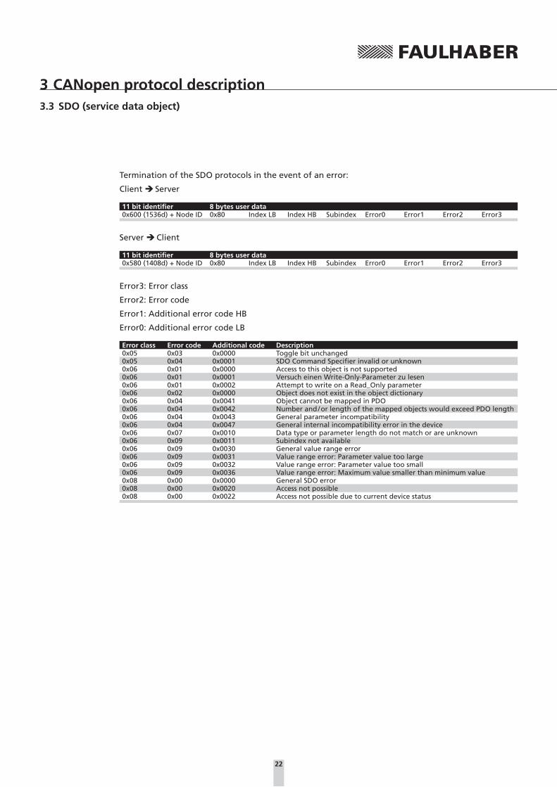
Termination of the SDO protocols in the event of an error:
Client Server
11 bit identifier 8 bytes user data0x600 (1536d) + Node ID 0x80 Index LB Index HB Subindex Error0 Error1 Error2 Error3
Server Client
11 bit identifier 8 bytes user data0x580 (1408d) + Node ID 0x80 Index LB Index HB Subindex Error0 Error1 Error2 Error3
Error3: Error class
Error2: Error code
Error1: Additional error code HB
Error0: Additional error code LB
Error class Error code Additional code Description0x05 0x03 0x0000 Toggle bit unchanged0x05 0x04 0x0001 SDO Command Specifier invalid or unknown0x06 0x01 0x0000 Access to this object is not supported0x06 0x01 0x0001 Versuch einen Write-Only-Parameter zu lesen0x06 0x01 0x0002 Attempt to write on a Read_Only parameter0x06 0x02 0x0000 Object does not exist in the object dictionary0x06 0x04 0x0041 Object cannot be mapped in PDO0x06 0x04 0x0042 Number and / or length of the mapped objects would exceed PDO length0x06 0x04 0x0043 General parameter incompatibility0x06 0x04 0x0047 General internal incompatibility error in the device0x06 0x07 0x0010 Data type or parameter length do not match or are unknown0x06 0x09 0x0011 Subindex not available0x06 0x09 0x0030 General value range error0x06 0x09 0x0031 Value range error: Parameter value too large0x06 0x09 0x0032 Value range error: Parameter value too small0x06 0x09 0x0036 Value range error: Maximum value smaller than minimum value0x08 0x00 0x0000 General SDO error0x08 0x00 0x0020 Access not possible0x08 0x00 0x0022 Access not possible due to current device status

23
3 CANopen protocol description
3.4 Emergency object (error message)
The emergency object informs other bus devices of errors that have occurred.
The size of the emergency object is always 8 bytes and its structure is as follows:
11 bit identifier 8 bytes user data0x80 (128d) + Node ID Error0 (LB) Error1 (HB) Error reg. FE0 (LB) FE1 (HB) 0 0 0
The first two bytes contain the 16 bit error code, the third byte contains the error register (content of object 0x1001), bytes 4 and 5 contain the 16 bit FAULHABER error register (content of object 0x2320), the remaining bytes are unused (always 0).
The error register identifies the error type. The individual error types are bit coded and are assigned the respective error codes in the following table. The object 0x1001 can be used to query the last value of the error register.
The following error code table lists all errors reported by emergency message frames, provided the corresponding error is set in the emergency mask for the FAULHABER error register (see Chapter 4.8 “Error handling”). Only those errors for which an emergency mask is given in this table are reported.
Emergency Error Codes
Error code Error Emergency mask Error register bit0x0000 No error0x1000 Generic error 00x2000 Current0x2300 Current, device output side0x2310 Continuous over current 0x0001 10x3000 Voltage0x3200 Voltage inside the device0x3210 Over voltage 0x0004 20x4000 Temperature0x4300 Drive temperature0x4310 Over temperature 0x0008 30x5000 Device hardware0x5500 Data storage0x5530 Flash memory error 0x0010 50x6000 Device software0x6100 Internal software 0x1000 50x8000 Monitoring0x8100 Communication0x8110 CAN overrun (objects lost) 0x0080 40x8120 CAN in error passive mode 0x0040 40x8130 Life guard or heartbeat error 0x0100 40x8140 Recovered from bus off 0x0200 40x8200 Protocol error0x8210 PDO not processed due to length
error0x4000 4
0x8220 PDO length exceeded 0x2000 40x8400 Velocity speed controller (deviation) 0x0002 50x8600 Positioning controller0x8611 Following error (deviation) 0x0002 50xFF00 Device specific0xFF01 Conversion overflow 0x0800 0

24
3 CANopen protocol description3.4 Emergency object (error message)
Error Register
Bit Meaning0 Generic error1 Current2 Voltage3 Temperature4 Communication error (overrun, error state)5 Device profile specific6 Reserved (always 0)
Example:
If, in the error mask of the FAULHABER error register 0x2321, bit 1 is set under subindex 1, an emer-gency telegram with 8 data bytes 0x10 0x23 0x01 0x00 0x00 0x00 0x00 0x00 is sent if the continuous current limiting value set via object 0x2333 is longer than the error delay time set via object 0x2322.
Handling CAN errors
CAN overrun (objects lost): If the Master sends telegrams faster than they can be processed by the Controller, messages are lost. The Controller reports this with the emergency telegram 0x8110. Bit 4 (communication error) is set in the error register and bit 7 (CAN overrun) is set in the FAULHABER error register. This error is sent with a time delay and is not withdrawn by an emergency telegram 0x000. The corresponding bits in the error register and in the FAULHABER error register are not deleted.
CAN in error passive mode: If errors occur on the CAN bus and the CAN module of the drive switches to “error passive” state, emergency telegram 0x8120 is sent. Bit 4 (communication error) is set in the error register and bit 6 (CAN in error passive mode) is set in the FAULHABER error register. The error is withdrawn if the drive switches back to “error active”.
Recovered from bus off: If the CAN module of the drive is in “bus-off” state and then receives valid messages again, the emergency telegram 0x8140 is sent to report that the “bus-off” state has been exited again. Bit 4 (communication error) is set in the error register and bit 9 (recovered from bus off) is set in the FAUL-HABER error register. This message is not withdrawn, the corresponding bits in the error register and in the FAULHABER error register are not deleted.
Deviation errors
If the maximum permissible velocity deviation set via object 0x2322.02 has been exceeded the emer-gency error 0x8611 is sent in Profile Velocity Mode and the emergency error 0x8400 is sent in Profile Position Mode. The error is reset if the DSP402 state machine switches or new positioning is started.

25
3 CANopen protocol description
3.5 SYNC Object
The SYNC object is a short message frame without data content, which is used to trigger synchronous PDOs and therefore enables quasi simultaneous starting of processes on different devices.
The identifier of the SYNC object can be set in the object dictionary under Index 0x1005 (default: 0x80).
11 bit identifier No user data0x80
Whether a PDO is to be triggered by a SYNC object or not can be set using the transmission type in the communication parameter objects of corresponding PDOs (see Chapter 6.1 “Communication objects according to CiA 301”).
A differentiation is made between the following PDO transmission types:
Transmission type Meaning255 Asynchronous (process-controlled)253 Asynchronous, only on request (RTR)
1 … 240 Synchronous, cyclicalPDO is repeatedly sent following a SYNC object The given value simultaneously represents the num-ber of SYNC objects which have to have been received before the PDO is sent again (1 = PDO is sent with each SYNC object).
0 Synchronous, acyclicPDO is sent or executed once following a SYNC object, if it has changed its content (new parameter query or status change)
Synchronous receive PDO:
The command transmitted with the PDO is not executed until the SYNC objects is received. In this way, e.g. several axles can be synchronised with each other.
NOTE In the case of RxPDOs, the transmission types 1-240 are identical to transmission type 0.
Synchronous transmit PDO:
After receiving a SYNC object, the PDO is sent as quickly as possible with the current data (Synchro-nous Window Length = 0):
SYNCObject
SynchronousWindowLength
SynchronousPDOs
AsynchronousPDOs
time
SYNCObject
SYNCObject
NOTE Transmission types 1-240 can also be used to group nodes.

26
3 CANopen protocol description
3.6 NMT (network management)
After switching on and initialisation has been successfully performed, the FAULHABER Motion Controllers are automatically in the “pre-operational” state. Apart from via NMT messages, in this state it is only possible to communicate with the device via service data objects (SDOs), to make or query parameter settings. FAULHABER Motion Controllers are delivered complete with useful default settings for all objects; therefore, in general it is not necessary to assign parameters with the system start. Necessary parameter settings are usually performed once, e.g. with the help of the FAULHABER Motion Manager and are then permanently stored in the data flash. These settings are then immedi-ately available following the system start.
Start a CANopen node (Start Remote Node):
11 bit identifier 2 bytes user data0x000 0x01 Node ID
Start the whole network (Start all Remote Nodes):
11 bit identifier 2 bytes user data0x000 0x01 0x00
The devices are then in “operational” state. The device is now fully functional and can be operated via PDOs.
The state diagram is given in the following:
(14)
(13)
(12)
(3)
(4) (5)(7)
(6)
(2)
(8) (9)
(10)
(11)
(1)Power on or Hardware Reset
Initialisation
Pre-Operational
Operational
Stopped
(1) At Power on the initialisation state is entered autonomously
(2) Initialisation finished – enter PRE-OPERA-TIONAL automatically
(3), (6) Start_Remote_Node indication
(4), (7) Enter PRE-OPERATIONAL_State indication
(5), (8) Stop_Remote_Node indication
(9), (10), (11) Reset_Node indication
(12), (13), (14) Reset_Communication indication
In the “Stopped” (“Prepared”) state, the device is in the error state and can no longer be operated using SDO and PDOs. Only NMT messages are received, to cause a state change. State changes can be performed with the help of the NMT services:
An NMT message frame always consists of 2 bytes on the identifier 0x000:
11 bit identifier 2 bytes user data0x000 CS Node ID
CS: Command specifier
Node ID: Node address (0 = all nodes)

27
3 CANopen protocol description3.6 NMT (network management)
The possible values for the Command Specifier CS are listed in the following table:
State transition Command Specifier CS Explanation(1) – The initialisation status is reached autonomously on switching on.(2) – Following initialisation the pre-operational status is reached automati-
cally, at the same time the boot-up message is sent.(3), (6) CS = 0x01 (1d) Start_Remote_Node. Starts the device and releases the transmission of
PDOs.(4), (7) CS = 0x80 (128d) Enter_Pre-Operational. Stops the PDO transmission, SDO continues to
be active.(5), (8) CS = 0x02 (2d) Stop_Remote_Node. Device changes to error state, SDO and PDO are
switched off.(9), (10), (11) CS = 0x81 (129d) Reset_Node. Performs a reset. All objects are reset to power-on de-
faults.(12), (13), (14) CS = 0x82 (130d) Reset_Communication. Resets the communication functions.
Boot-Up Message:
Following the initialisation phase, the FAULHABER Motion Controller sends the Boot-Up Message, a CAN message with one data byte (Byte0 = 0x00) on the identifier of the node guarding message (0x700 + Node ID):j
11 bit identifier 1 bytes user data0x700 (1792d) + Node ID 0x00
The boot-up message signals the end of the initialisation phase of a newly activated module, which can then be configured or started.
Node guarding / life guarding:
The node guarding object can be used to query the momentary state of the device. To do this, by setting a remote frame, the master sends a request (request message frame) on the guarding identi-fier of the node to be monitored. This then replies with the guarding message, which contains the current status of the node and a toggle bit.
The following diagram describes the node guarding protocol:
indication
indication
response
indication
response
Life Guarding Event*
request
request
NMT Master NMT SlaveCOB-ID = 1792 + Node-ID
COB-ID = 1792 + Node-ID
0 1
0 1
confirm
confirm
indication
Node Guarding Event*
Node Life Time
NodeGuardTime
*if guarding error
Remote transmit request
Node/Life Guarding
Remote transmit request
7t
6…0s
7t
6…0s
t: Toggle bit. Initially 0, changes its value in each guarding message frame.
s: Status:
s = 0x04 (4d): Stopped
s = 0x05 (5d): Operational
s = 0x7F (127d): Pre-operational
If a node life time > 0 is set (objects 0x100C and 0x100D), a life-guarding-error is set, if no more node guarding queries of the master arrive within the given life time (life-guarding).
The response to a life-guarding-error can be set via the error mask of the FAULHABER error register (object 0x2321). By default the emergency telegram 0x8130 is sent.

28
3 CANopen protocol description3.6 NMT (network management)
Heartbeat:
The Motion Controller can not only be set as the Heartbeat Producer but also as the Heartbeat Con-sumer.
A heartbeat producer cyclically sends a message, which is received by one or several heartbeat con-sumers in the network. Application of a heartbeat consumer can therefore respond, if no heartbeat message of the heartbeat producer to be monitored arrives within the heartbeat consumer time.
The following diagram describes the Heartbeat protocol:
indication
indication
indication
Heartbeat Event
request
HeartbeatProducer
HeartbeatConsumer
COB-ID = 1792 + Node-ID
0 1
HeartbeatProducer
Time HeartbeatConsumer
Time
HeartbeatConsumer
Time
7r
6…0s
indication
indication
indication
request
0 1
7r
6…0s
r: Reserved (always 0)
s: Status of the Heartbeat Producer
s = 0x00 (0d): Bootup
s = 0x04 (4d): Stopped
s = 0x05 (5d): Operational
s = 0x7F (127d): Pre-operational
If a producer heartbeat time > 0 is set (object 0x1017) the Motion Controller functions as a heartbeat producer and sends a heartbeat message at the set time interval.
After switching on the bootup message corresponds to the first heartbeat message. Further heart-beats follow at intervals equal to the heartbeat producer time.
NOTEOnly one of the two monitoring mechanisms, lifeguarding or heartbeat, may be activated!
If an attempt is made to set a node guarding time > 0 while heartbeat producer is activated, the SDO error 0x08000020 is sent. If a producer heartbeat time > 0 is set, the node guarding times are set to 0.
The Motion Controller can also act as a heartbeat consumer, in order to monitor the presence of the master.
If, in addition to the producer heartbeat time, a consumer heartbeat time > 0 is set (object 0x1016.01) this monitoring mechanism is activated in the Motion Controller. In this case the node ID of the master to be monitored and the monitoring time (heartbeat consumer time) must be entered here; this must always be larger than the heartbeat producer time of the master.
If the Motion Controller then does not receive any heartbeat message from the master within the set heartbeat consumer time, a heartbeat event is triggered. The response to a heartbeat event can be set using the error mask of the FAULHABER error register (Object 0x2321). By default, the emergency telegram 0x8130 is sent.
NOTEIn the event of fatal communication errors by default the FAULHABER Motion Controllers switch to the NMT “Pre-Operational” state. If another behaviour is required it can be set using object 0x1029.

29
3 CANopen protocol description3.6 NMT (network management)
Identifier distribution:
CANopen provides default identifiers in the ”predefined connection set” for the most important objects. These are made up of a 7 bit node address (node ID) and a 4 bit function code in accordance with the following schema:
Function Code
10Bit-No.:COB-Identifier
0
Node-ID
Following the first allocation of a valid node number via the LSS protocol the FAULHABER Motion Controllers operate with these default identifiers (COB IDs):
Object Function code (binary) Resulting COB ID Communication parameters at indexNMT 0000 0 –SYNC 0001 128 (80h) 1005h
Object Function code (binary) Resulting COB ID Communication parameters at indexEMERGENCY 0001 129 (81h) – 255 (FFh) 1014hPDO1 (tx) 0011 385 (181h) – 511 (1FFh) 1800hPDO1 (rx) 0100 513 (201h) – 639 (27Fh) 1400hPDO2 (tx) 0101 641 (281h) – 767 (2FFh) 1801hPDO2 (rx) 0110 769 (301h) – 895 (37Fh) 1401hPDO3 (tx) 0111 897 (381h) – 1023 (3FFh) 1802hPDO3 (rx) 1000 1025 (401h) – 1151 (47Fh) 1402hPDO4 (tx) 1001 1153 (481h) – 1279 (4FFh) 1803hPDO4 (rx) 1010 1281 (501h) – 1407 (57Fh) 1403hSDO (tx) 1011 1409 (581h) – 1535 (5FFh) 1200hSDO (rx) 1100 1537 (601h) – 1663 (67Fh) 1200hNMT error control 1110 1793 (701h) – 1919 (77Fh)
The COB IDs of the PDOs, of the SYNC object and the EMERGENCY object can be changed via the object dictionary.
NOTE If the node number is changed via the LSS protocol the COB IDs of the PDOs and the EMCY object remain unchanged. If, after changing the node number, these COB IDs are once again to be set according to the prede-fined connection set, the node number 0xFF (255) must be set beforehand (unconfigured LSS nodes). If the node number is changed via the Motion Manager the changeover to the predefined connec-tion set takes place automatically, so that all COB IDs are once again set according to the new num-ber. With this process all other communication settings are also set to their default values.

30
3 CANopen protocol description
3.7 Entries in the object dictionary
The configuration parameters are managed in the CANopen object dictionary. The object dictionary is divided into three areas:
1. Communication parameters (index 0x1000 – 0x1FFF)
2. Manufacturer specific area (index 0x2000 – 0x5FFF)
3. Standardised device profiles (0x6000 – 0x9FFF)
The 1st area contains the objects according to DS301, the 2nd area is reserved for manufacturer-spe-cific objects and the 3rd area contains the objects according to DSP402 supported by the FAULHABER Motion Controllers.
Each object can be referenced via its index and subindex (SDO protocol).
Overview of the available objects:
a.) Communication objects according to CiA DS301:
Index Sub-index
Name Typ Attr. Map Meaning
0x1000 Device type Unsigned32 ro Device type0x1001 Error register Unsigned8 ro yes Error register0x1003 Predefined error field ARRAY rw Fault memory
0 Number of errors Unsigned8 rw1 Standard error field Unsigned32 ro2 Standard error field Unsigned32 ro
0x1005 COB ID SYNC Unsigned32 rw Identifier of the SYNC object0x1008 Manufacturer device name String const Device names0x1009 Manufacturer hardware version String const Hardware version0x100A Manufacturer software version String const Software version0x100C Guard time Unsigned16 rw Lifeguarding monitoring time0x100D Life time factor Unsigned8 rw Lifeguarding factor0x1010 Store parameters ARRAY Save
0 Number of entries Unsigned8 ro1 Save all parameters Unsigned32 rw2 Save communication parameters Unsigned32 rw3 Save application parameters Unsigned32 rw
0x1011 Restore default parameters ARRAY Restore0 Number of entries Unsigned8 ro1 Restore all factory parameters Unsigned32 rw Factory settings2 Restore factory communication
parametersUnsigned32 rw
3 Restore factory application param-eters
Unsigned32 rw
4 Restore all saved parameters Unsigned32 rw Last saved settings5 Restore saved communication
parametersUnsigned32 rw
6 Restore saved application param-eters
Unsigned32 rw
0x1014 COB ID EMCY Unsigned32 rw Identifier of the emergency object0x1016 Consumer heartbeat time ARRAY rw Heartbeat monitoring time
0 Number of entries Unsigned8 ro1 Consumer heartbeat time Unsigned32 rw
0x1017 Producer heartbeat time Unsigned16 rw Heartbeat send time interval0x1018 Identity object RECORD Device identity
0 Number of entries Unsigned8 ro1 Vendor ID Unsigned32 ro2 Product code Unsigned32 ro3 Revision number Unsigned32 ro4 Serial number Unsigned32 ro
0x1029 Error behaviour Behaviour in the event of faults0 Number of entries Unsigned8 ro1 Communication error Unsigned8 rw

31
3 CANopen protocol description3.7 Entries in the object dictionary
Index Sub-index
Name Typ Attr. Map Meaning
Server SDO parameter0x1200 1st server SDO parameter SDO RECORD SDO settings
0 Number of entries Unsigned8 ro1 COB ID client to server (rx) Unsigned32 ro2 COB ID server to client (tx) Unsigned32 ro
Receive PDO communication parameter0x1400 Receive PDO1 communication
parameterRECORD RxPDO1 communication parameter
0 Number of entries Unsigned8 ro1 COB ID Unsigned32 rw2 Transmission type Unsigned8 rw
0x1401 Receive PDO2 communication parameter
RECORD RxPDO2 communication parameter
0 Number of entries Unsigned8 ro1 COB ID Unsigned32 rw2 Transmission type Unsigned8 rw
0x1402 Receive PDO3 communication parameter
RECORD RxPDO3 communication parameter
0 Number of entries Unsigned8 ro1 COB ID Unsigned32 rw2 Transmission type Unsigned8 rw
0x1403 Receive PDO4 communication parameter
RECORD RxPDO4 communication parameter
0 Number of entries Unsigned8 ro1 COB ID Unsigned32 rw2 Transmission type Unsigned8 rw
Receive PDO mapping parameter0x1600 Receive PDO1 mapping parameter RECORD RxPDO1 mapping parameter
0 Number of mapped objects Unsigned8 rw Default: 11 PDO mapping entry 1 Unsigned32 rw Default: 0x60402 PDO mapping entry 2 Unsigned32 rw Default: 0x03 PDO mapping entry 3 Unsigned32 rw Default: 0x04 PDO mapping entry 4 Unsigned32 rw Default: 0x0
0x1601 Receive PDO2 mapping parameter RECORD RxPDO2 mapping parameter0 Number of mapped objects Unsigned8 rw Default: 21 PDO mapping entry 1 Unsigned32 rw Default: 0x60402 PDO mapping entry 2 Unsigned32 rw Default: 0x607A3 PDO mapping entry 3 Unsigned32 rw Default: 0x04 PDO mapping entry 4 Unsigned32 rw Default: 0x0
0x1602 Receive PDO3 mapping parameter RECORD RxPDO3 mapping parameter0 Number of mapped objects Unsigned8 rw Default: 21 PDO mapping entry 1 Unsigned32 rw Default: 0x60402 PDO mapping entry 2 Unsigned32 rw Default: 0x60FF3 PDO mapping entry 3 Unsigned32 rw Default: 0x04 PDO mapping entry 4 Unsigned32 rw Default: 0x0
0x1603 Receive PDO4 mapping parameter RECORD RxPDO4 mapping parameter0 Number of mapped objects Unsigned8 rw Default: 21 PDO mapping entry 1 Unsigned32 rw Default: 0x60402 PDO mapping entry 2 Unsigned32 rw Default: 0x257A3 PDO mapping entry 3 Unsigned32 rw Default: 0x04 PDO mapping entry 4 Unsigned32 rw Default: 0x0
32
3 CANopen protocol description3.7 Entries in the object dictionary
Index Sub-index
Name Typ Attr. Map Meaning
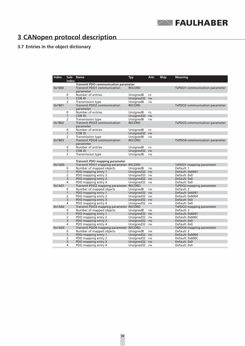
Transmit PDO communication parameter0x1800 Transmit PDO1 communication
parameterRECORD TxPDO1 communication parameter
0 Number of entries Unsigned8 ro1 COB ID Unsigned32 rw2 Transmission type Unsigned8 rw
0x1801 Transmit PDO2 communication parameter
RECORD TxPDO2 communication parameter
0 Number of entries Unsigned8 ro1 COB ID Unsigned32 rw2 Transmission type Unsigned8 rw
0x1802 Transmit PDO3 communication parameter
RECORD TxPDO3 communication parameter
0 Number of entries Unsigned8 ro1 COB ID Unsigned32 rw2 Transmission type Unsigned8 rw
0x1803 Transmit PDO4 communication parameter
RECORD TxPDO4 communication parameter
0 Number of entries Unsigned8 ro1 COB ID Unsigned32 rw2 Transmission type Unsigned8 rw
Transmit PDO mapping parameter0x1A00 Transmit PDO1 mapping parameter RECORD TxPDO1 mapping parameter
0 Number of mapped objects Unsigned8 rw Default: 11 PDO mapping entry 1 Unsigned32 rw Default: 0x60412 PDO mapping entry 2 Unsigned32 rw Default: 0x03 PDO mapping entry 3 Unsigned32 rw Default: 0x04 PDO mapping entry 4 Unsigned32 rw Default: 0x0
0x1A01 Transmit PDO2 mapping parameter RECORD TxPDO2 mapping parameter0 Number of mapped objects Unsigned8 rw Default: 21 PDO mapping entry 1 Unsigned32 rw Default: 0x60412 PDO mapping entry 2 Unsigned32 rw Default: 0x60643 PDO mapping entry 3 Unsigned32 rw Default: 0x04 PDO mapping entry 4 Unsigned32 rw Default: 0x0
0x1A02 Transmit PDO3 mapping parameter RECORD TxPDO3 mapping parameter0 Number of mapped objects Unsigned8 rw Default: 21 PDO mapping entry 1 Unsigned32 rw Default: 0x60412 PDO mapping entry 2 Unsigned32 rw Default: 0x606C3 PDO mapping entry 3 Unsigned32 rw Default: 0x04 PDO mapping entry 4 Unsigned32 rw Default: 0x0
0x1A03 Transmit PDO4 mapping parameter RECORD TxPDO4 mapping parameter0 Number of mapped objects Unsigned8 rw Default: 21 PDO mapping entry 1 Unsigned32 rw Default: 0x60642 PDO mapping entry 2 Unsigned32 rw Default: 0x606C3 PDO mapping entry 3 Unsigned32 rw Default: 0x04 PDO mapping entry 4 Unsigned32 rw Default: 0x0

33
3 CANopen protocol description3.7 Entries in the object dictionary
b.) Manufacturer-specific objects:
Index Sub-index
Name Typ Attr. Map Meaning
0x2310 Digital input settings ARRAY Digital input setting0 Number of entries Unsigned8 ro1 Negative limit switch Unsigned8 rw2 Positive limit switch Unsigned8 rw3 Homing switch Unsigned8 rw5 Switch polarity Unsigned8 rw6 Polarity for homing limit Unsigned8 rw
0x2311 Digital input status ARRAY State of the digital inputs0 Number of entries Unsigned8 ro1 Input status Unsigned8 ro yes2 Input level Unsigned8 ro yes
0x2313 Analog input status ARRAY Analog input voltages [mV]0 Number of entries Unsigned8 ro1 Inp. 1 ADC value Integer16 ro yes3 Inp. 3 ADC value Integer16 ro yes4 Inp. 4 ADC value Integer16 ro yes (only MCDC)5 Inp. 5 ADC value Integer16 ro yes (only MCDC)
0x2314 Analog input status raw ARRAY Analog input voltages in digits0 Number of entries Unsigned8 ro1 Inp. 1 ADC value raw Integer16 ro yes2 Inp. 2 ADC value raw Integer16 ro yes3 Inp. 3 ADC value raw Integer16 ro yes4 Inp. 4 ADC value raw Integer16 ro yes5 Inp. 5 ADC value raw Integer16 ro yes6 Inp. 6 ADC value raw Integer16 ro yes7 Inp. 7 ADC value raw Integer16 ro yes8 Inp. 8 ADC value raw Integer16 ro yes
0x2315 Fault-pin settings ARRAY Fault pin setting0 Number of entries Unsigned8 ro1 Fault-pin function Unsigned8 rw3 Digital output status Unsigned8 rw / ro *) yes
0x2316 Input threshold level Unsigned8 rw Switching level of the digital inputs0x2320 FAULHABER fault register Unsigned16 ro yes FAULHABER fault register0x2321 Error mask ARRAY Error masks
0 Number of entries Unsigned8 ro1 Emergency mask Unsigned16 rw2 Fault mask Unsigned16 rw3 Errout mask Unsigned16 rw
0x2322 Error handling ARRAY Error handling0 Number of entries Unsigned8 ro1 Error delay Unsigned16 rw2 Deviation Unsigned16 rw
0x2323 Device status ARRAY Current device status0 Number of entries Unsigned8 ro1 Housing temperature Unsigned16 ro yes2 Internal temperature Unsigned16 ro yes3 Max. temperature limit Unsigned16 ro4 Min. temperature limit Unsigned16 ro
0x2330 Filter settings ARRAY Filter parameters0 Number of entries Unsigned8 ro1 Sampling rate Unsigned16 rw2 Gain scheduling Unsigned16 rw
0x2331 Velocity control parameter set ARRAY Velocity controller parameters0 Number of entries Unsigned8 ro1 Proportional term POR Unsigned16 rw yes2 Integral term I Unsigned16 rw yes
0x2332 Position control parameter set ARRAY Position controller parameters0 Number of entries Unsigned8 ro1 Proportional term PP Unsigned16 rw yes2 Derivative term PD Unsigned16 rw yes
0x2333 Current control parameter set ARRAY Current controller parameters0 Number of entries Unsigned8 ro1 Continuous current limit Unsigned16 rw yes2 Peak current limit Unsigned16 rw yes3 Integral term CI Unsigned16 rw yes
0x2334 Actual current limit Unsigned16 ro yes Current current limiting
*) Dependent on the configuration of the motion controller

34
3 CANopen protocol description3.7 Entries in the object dictionary
Index Sub-index
Name Typ Attr. Map Meaning
0x2338 General settings ARRAY General controller settings0 Number of entries Unsigned8 ro1 Pure sinus commutation Unsigned16 rw (not MCDC)2 Activate position limits in velocity
modeUnsigned16 rw
3 Activate position limits in position mode
Unsigned16 rw
0x2350 Motor data RECORD Motor data0 Number of entries Unsigned8 ro1 Speed constant KN Unsigned16 rw2 Terminal resistance RM Unsigned32 rw3 Pole number Unsigned16 rw (not MCDC)5 Thermal time constant TW1 Unsigned16 rw
0x2351 Encoder data RECORD Encoder data0 Number of entries Unsigned8 ro1 Sensor type Unsigned8 rw2 Resolution external encoder Unsigned32 rw3 Resolution internal encoder Unsigned32 ro
0x2361 Velocity actual value unfiltered Integer16 ro yes Actual speed unfiltered0x2400 Baudrate set Unsigned8 ro Set baud rate0x2562 Position demand internal value Integer32 ro yes Last target position in internal units0x257A Target position internal value Integer32 rw yes Target position in increments0x257B Position range limit internal value ARRAY Internal position limits in incre-
ments0 Number of entries Unsigned8 ro1 Min. position range limit Integer32 ro yes2 Max. position range limit Integer32 ro yes
0x257D Software position limit internal value
ARRAY Position limits in increments
0 Number of entries Unsigned8 ro1 Min. position limit Integer32 rw yes2 Max. position limit Integer32 rw yes
*) Dependent on the configuration of the motion controller

35
3 CANopen protocol description3.7 Entries in the object dictionary
c.) Objects of the drive profile according to CiA DSP402:
Index Sub-index
Name Typ Attr. Map Meaning
0x6040 Controlword Unsigned16 rw yes Drive control0x6041 Statusword Unsigned16 ro yes Status display0x6060 Modes of operation Integer8 rw yes Operating mode changeover0x6061 Modes of operation display Integer8 ro yes Set operating mode0x6062 Position demand value Integer32 ro yes Last target position scaled0x6063 Position actual internal value Integer32 ro yes Actual position in increments0x6064 Position actual value Integer32 ro yes Actual position scaled0x6067 Position window Unsigned32 rw yes Target position window0x6068 Position window time Unsigned16 rw yes Time in target position window0x606B Velocity demand value Integer32 ro yes Target velocity0x606C Velocity actual value Integer32 ro yes Current speed value0x606D Velocity window Unsigned16 rw yes End velocity window0x606E Velocity window time Unsigned16 rw yes Time in end velocity window0x606F Velocity threshold Unsigned16 rw yes Velocity threshold value0x6070 Velocity threshold time Unsigned16 rw yes Velocity threshold time0x6078 Current actual value Unsigned16 ro yes Current value0x607A Target position Integer32 rw yes Target position0x607B Position range limit ARRAY Maximum range limits
0 Number of entries Unsigned8 ro1 Min. position range limit Integer32 rw2 Max. position range limit Integer32 rw
0x607C Homing offset Integer32 rw yes Reference point offset0x607D Software position limit ARRAY Set range limits
0 Number of entries Unsigned8 ro1 Min. position limit Integer32 rw yes2 Max. position limit Integer32 rw yes
0x607E Polarity Unsigned8 rw yes Polarity (direction of rotation)0x607F Max. profile velocity Unsigned32 rw yes Maximum permissible velocity0x6081 Profile velocity unsigned32 rw yes Maximum velocity during operation0x6083 Profile acceleration Unsigned32 rw yes Acceleration value0x6084 Profile deceleration Unsigned32 rw yes Braking ramp value0x6085 Quick stop deceleration Unsigned32 rw yes Quick stop braking ramp value0x608F Position encoder resolution ARRAY Encoder resolution for factor con-
version0 Number of entries Unsigned8 ro1 Encoder increments Unsigned32 ro2 Motor revolutions Unsigned32 ro
0x6091 Gear ratio ARRAY Gear conversion factor0 Number of entries Unsigned8 ro1 Motor revolutions Unsigned32 rw2 Shaft revolutions Unsigned32 rw
0x6092 Feed constant ARRAY Feed conversion factor0 Number of entries Unsigned8 ro1 Feed Unsigned32 rw2 Shaft revolutions Unsigned32 rw
0x6093 Position factor ARRAY rw Position conversion factor0 Number of entries Unsigned8 ro1 Position factor numerator Unsigned32 ro2 Position factor divisor Unsigned32 ro
0x6098 Homing method Integer8 rw yes Homing method0x6099 Homing speed ARRAY Homing velocity
0 Number of entries Unsigned8 ro1 Switch seek velocity Unsigned32 rw yes2 Homing velocity Unsigned32 rw yes
0x609A Homing acceleration Unsigned32 rw yes Homing acceleration0x60FA Control effort Integer32 ro yes Controller output0x60FD Digital inputs Unsigned32 ro yes State of digital inputs0x60FF Target velocity Integer32 rw yes Target velocity0x6502 Supported drive modes Unsigned32 ro yes Supported operating modes
“Yes” in the “Map” column indicates that PDO mapping is supported for this object (see Chapter 3.2 “PDOs (process data objects)”).
A detailed description of the individual objects is given in Chapter 6 “Parameter description”.

36
4 Functional description
The CANopen device profile for drives and Motion Control applications (CiA 402) of the CANopen user organisation CAN in Automation (CiA) is based on the general CANopen protocol description CiA 301 as described in Chapter 4.
Communication with the drive takes place via the mechanisms described there. Before the drive can be addressed the baud rate must be set and a node number assigned to the CAN node. In addition, the underlying CANopen node must be activated using the network management (NMT) (see Chap-ter 3.6 “NMT (network management)”).
Guide
Device control Page 37
Profile position mode and position control function Page 45
Homing mode Page 50
Profile velocity mode Page 54
Drive data Page 57

37
4 Functional description
4.1 Device control
FAULHABER Motion Control systems support “device control” from the CiA 402 profile and the “pro-file position mode”, “profile velocity mode” and “homing mode” operating modes.
4.1.1 State machine of the drive
Motor
ProfileVelocityMode
ProfilePositionMode
HomingMode
Modes of operation
Device Controlstate machine
Drive Profile 402
Application layer and communication profile DS 301
CAN network
CAN node
The drive behaviour is mapped in CANopen via a state machine. The states can be controlled with the controlword and displayed with the status-word:
0 14
15
13
1
2
9
8
10
1212
11
16
7
3 6
4 5
StartFault
Reaction Active
FaultNot Ready to
Switch On
Ready toSwitch On
Switched On
OperationEnable
Quick StopActive
Switch OnDisabled
Power Disabled
Fault
Power Enabled
After switching on and the initialisation has been successfully performed, the FAULHABER drive is immediately in “switch on disabled” state. At the same time, transitions 0 and 1 are run through autonomously.
A change in state within the state machine of the drive according to CiA 402 cannot be made until the underlying CANopen node is in the “operational” state (see Chapter 3.6 “NMT (network man-agement)”).
The “shutdown” command places the drive in “ready to switch on” state (transition 2).
The “switch on” command then switches on the power stage. The drive is now enabled and is in “switched on” state (transition 3).
The “enable operation” command places the drive in “operation enabled” state, the drive’s normal operating mode (transition 4). The “disable operation” command places the drive back in “switched on” state and is used, e.g. to terminate a running operation (transition 5).

38
4 Functional description4.1 Device control
The state changes shown in the diagram are executed by the following commands:
Command TransitionsShutdown 2, 6, 8Switch on 3Disable voltage 7, 9, 10, 12Quick stop 7, 10, 11Disable operation 5Enable operation 4, 16Fault reset 15
Controlword (0x6040)
The commands for executing state changes are executed by a combining bits 0 – 3 in the control-word. The controlword is located in the object dictionary under index 0x6040 and is usually transmit-ted with PDO1.
Index Sub-index
Name Type Attr. Default value
Meaning
0x6040 0 Controlword Unsigned16 rw 0 Drive control
The bits in the controlword have the following meaning:
Bit Function Commands for device control state machine
Shu
t-d
ow
n
Swit
ch o
n
Dis
able
vo
lt-
age
Qu
ick
sto
p
Dis
able
o
per
atio
n
Enab
le
op
erat
ion
Fau
lt r
eset
0 Switch on 0 1 X X 1 1 X1 Enable voltage 1 1 0 1 1 1 X2 Quick stop 1 1 X 0 1 1 X3 Enable operation X 0 X X 0 1 X4 New set-point /homing operation start5 Change set immediately6 abs / rel7 Fault reset 0->18 Halt9 010 011 012 013 014 015 0
Meaning of the other bits in the controlword:
Function DescriptionNew set-point 0: No new target position specified
1: New target position specifiedChange set immediately Not used. New positioning jobs are always started immediately.abs / rel 0: Target position is an absolute value
1: Target position is a relative valueFault reset 0->1: Reset faultHalt 0: Movement can be made
1: Stop drive
The command sequences for starting a positioning, a speed control operation or a homing sequence are explained in the following sections.

39
4 Functional description4.1 Device control
Example
Step sequence of the transitions in order to set a drive in Enable Operation state:
1. Shutdown:
Controlword = 0x00 06
2. Switch on:
Controlword = 0x00 07
The drive is then in “Switched On” status. Operation must then be released to enable drive com-mands to be executed:
3. Enable operation:
Controlword = 0x00 0F
The drive is then in “Operation Enabled” state, in which it can be operated using the correspond-ing objects of the preset mode.
Example
Step sequence of the transitions to get a drive from the error state:
1. Fault reset:
Controlword = 0x00 80
2. Shutdown:
Controlword = 0x00 06
3. Switch on:
Controlword = 0x00 07
The drive is then in “Switched On” status. Operation must then be released to enable drive com-mands to be executed:
4. Enable Operation:
Controlword = 0x00 0F
The drive is then in “Operation Enabled” state, in which it can be operated using the correspond-ing objects of the preset mode.
NOTE The current state of the drive state machine (see Chapter 4.1.1 “State machine of the drive”) is indi-cated by bits 0 … 6 of the statusword.
Important In all cases, only the transitions defined in the current state can be implemented!
Quick stop:
The drive is decelerated with the deceleration ramp given under quick stop deceleration (0x6085). It then maintains its current position in profile position mode.
Statusword (0x6041)
The drive’s current status is mapped in bits 0 – 6 of the statusword. In the event of status changes, in its default setting, the FAULHABER Motion Controller automatically sends all PDOs, which contain the statusword. The statusword is located in the object dictionary under Index 0x6041.
Index Sub-index
Name Type Attr. Default value
Meaning
0x6041 0 Statusword Unsigned16 ro 0 Status display

40
4 Functional description4.1 Device control
The bits of the statusword have the following meaning:
Bit Function State of the device control state machine
No
t re
ady
to
swit
ch o
n
Swit
ch o
n
dis
able
d
Rea
dy
to
swit
ch o
n
Swit
ched
on
Op
erat
ion
en
able
d
Qu
ick
sto
p
acti
ve
Fau
lt r
eac-
tio
n a
ctiv
e
Fau
lt
0 Ready to switch on 0 0 1 1 1 1 1 01 Switched on 0 0 0 1 1 1 1 02 Operation enabled 0 0 0 0 1 1 1 03 Fault 0 0 0 0 0 0 1 14 Voltage enabled X X X X X X X X5 Quick stop X X 1 1 1 0 X X6 Switch on disabled 0 1 0 0 0 0 0 07 Warning8 09 Remote10 Target reached11 Internal limit active12 Set-point acknowledge /speed / hom-
ing attained13 Deviation error14 015 0
Meaning of the other bits in the statusword:
Function DescriptionWarning not usedRemote not usedTarget reached 0: Target position or target velocity not yet reached
1: Target position or target velocity reached. (Halt = 1: Drive has reached speed 0)
Set-point acknowledge
Homing attained
Speed
0: New target position not yet adopted (profile position mode)1: New target position adopted0: Homing position not yet detected1: Homing position detected0: Speed not equal to 0 (profile velocity mode)1: Speed 0
Deviation error 0: No error1: Error
Bit 10 (target reached) is set if the drive has reached its target position in profile position mode or has reached its target velocity in profile velocity mode. Specification of a new target value deletes the bit.
Bit 11 (internal limit active) indicates that a internal range limit has been reached.
Bit 12 (Setpoint acknowledge / Speed) is set after receiving a new positioning command (controlword with new setpoint) and is reset when the new setpoint has been reset in the controlword (handshake for positioning command). In Profile Velocity Mode the bit is set at speed 0 and is reset if speed is not equal to 0.
NOTEIn the "Fault reaction active" state the drive is stopped with the deceleration ramp set in object 0x6084 and then in "Fault" state it attempts to keep the velocity at zero.

41
4 Functional description4.1 Device control
4.1.2 Selection of the operating mode
The modes of operation parameter is used to select the active drive profile, the modes of operation display entry can be used to read back the current mode of operation.
Modes of Operation (0x6060)
Index Sub-index
Name Type Attr. Default value
Meaning
0x6060 0 Modes of operation Integer8 rw 1 Operating mode changeover
FAULHABER Motion Control systems support the following operating modes:
1 CiA 402 profile position mode (position control)
3 CiA 402 profile velocity mode (velocity control)
6 CiA 402 homing mode (homing)
The operating modes according to CiA 402 are described in the following sections.
Modes of Operation Display (0x6061)
Index Sub-index
Name Type Attr. Default value
Meaning
0x6061 0 Modes of operation display Integer8 ro 1 Display of the set operating mode
The set operating mode can be queried here, the meaning of the return values corresponds to the values of the object 0x6060.

42
4 Functional description
4.2 Factor group
The objects of the factor group can be used to convert the internal position values into user defined units. Internal position values are given in increments and are dependent on the resolution of the encoder used. User-defined units depend on the respective encoder resolution and on attached linear reduction.
Current position in user-defined units:
position actual value =position actual internal value × feed constant
position encoder resolution × gear ratio
Gear ratio between revolutions at the motor and at the output:
gear ratio =motor revolutions
shaft revolutions
Revolutions at the output:
feed constant =feed
shaft revolutions
Encoder resolution
position encoder resolution =encoder increments
motor revolutions
The following chart gives the conversion from user units into internal units using the parameters of the position factor object (0x6093). Position factor only shows an intermediate value, which is calcu-lated from the parameters of the position encoder resolution (0x608F), gear ratio (0x6091) and feed constant (0x6092) objects. Position encoder resolution also only shows an intermediate value which, depending on the sensor type selected via the encoder data object (0x2351), contains the respective encoder resolution.
× =
0x608F.01Encoder
increments
0x6091.01Motor
revolutions
0x6092.02Shaft
revolutions× ×
× ×0x608F.02
Motorrevolutions
0x6091.02Shaft
revolutions
0x6092.01Feed
0x6093.01Position factor
numerator
0x6093.02Position factor
divisor
0x6064Position actual
value
0x6063Position actualinternal value
read/write
read only
MCBL MCDC
0x2351.02Ext. Encoder resolution
0x2351.02Ext. Encoder resolution
0x2351.03Int. Encoder
resolution (3000)
0x2351.01Sensor Type

43
4 Functional description4.2 Factor group
When setting the conversion factors ensure that the resulting resolution is still large enough. The maximum resolution with user units is obtained with gear ratio = 1 and feed constant = encoder resolution. Further, it must also be noted that the counter of the position factor is always smaller than 2 × 10⁹.
As the numerator and the denominator of the actual position factor are calculated from the indi-vidual conversion factors, a number overflow can occur during the transmission, which is signalled by the SDO error 0x06040047. This error can also occur on switching over the sensor type or on chang-ing the encoder resolution.
If an overflow occurs during subsequent calculations the emergency telegram 0xFF01 is sent and bit 11 (conversion overflow) is set in the FAULHABER error register. If there are no longer any conversion errors after correcting the factors, the error is deleted and the emergency telegram 0x0000 is sent.
NOTE The Motion Controller basically manages its position parameters in internal units. These are only converted with the help of the position factor on writing or reading out. For this reason the fac-tor group should be set before the very first parameterisation and if possible should no longer be changed!
Position Encoder Resolution (0x608F)
Index Sub-index
Name Typ Attr. Default value Meaning
0x608F 0 Number of entries Unsigned8 ro 2 Number of object entries1 Encoder increments Unsigned32 ro 3 000 / 2 048 *) Position resolution of the set
sensor2 Motor revolutions Unsigned32 ro 1 Number of motor revolutions
with the pulse rate named in subindex 1
*) BL-Controller / MCDC (MCBL-AES: 4096)
Gear Ratio (0x6091)
Index Sub-index
Name Typ Attr. Default value Meaning
0x6091 0 Number of entries Unsigned8 ro 2 Number of object entries1 Motor revolutions Unsigned32 rw 1 Number of motor revolutions2 Shaft revolutions Unsigned32 rw 1 Number of revolutions of the
output shaft
Feed Constant (0x6092)
Index Sub-index
Name Typ Attr. Default value Meaning
0x6092 0 Number of entries Unsigned8 ro 2 Number of object entries1 Feed Unsigned32 rw 3 000 / 2 048 *) Feed in user units2 Shaft revolutions Unsigned32 rw 1 Number of revolutions of the
output shaft
*) BL-Controller / MCDC (MCBL-AES: 4096)
On delivery the user units are set according to the encoder resolution, i.e. positioning takes place in internal units. In the case of the brushless controllers these are 3 000 incr/rev, for the MCDC 2 048 incr/rev and for the MCBL-AES: 4096 incr/rev

44
4 Functional description4.2 Factor group
NOTEIf you set a different encoder resolution and want to keep the same maximum internal resolution as before, set the feed constant to the same resolution; otherwise the preset user units are retained.
Example of user units in angular degrees:
Set the feed constant to 360 per revolution in order to obtain a 1° resolution.
Position Factor (0x6093)
Index Sub-index
Name Type Attr. Default value Meaning
0x6093 0 Number of entries Unsigned8 ro 2 Number of object entries1 Position factor numerator Unsigned32 ro 1 Numerator of the position
factor2 Position factor divisor Unsigned32 ro 1 Denominator (divisor) of the
position factor
This object is only used to display the conversion factor set using the gear ratio (0x6091), feed con-stant (0x6092) and position encoder resolution (0x608F).
Polarity (0x607E)
Index Sub-index
Name Type Attr. Default value Meaning
0x607E 0 Polarity Unsigned8 rw 0 Direction of rotation
This object can be used to globally change the direction of rotation, i.e. the default and actual values for the position and speed are multiplied by –1:
Bit 7 = 1 negative direction of rotation in positioning mode
Bit 6 = 1 negative direction of rotation in velocity mode
NOTE The change to the position factor and polarity affects the set values for the position range limit (0x607B), software position limit (0x607D), position window (0x6067) and homing offset (0x607C), which change accordingly. These values must then be checked again and if necessary adjusted! In the case of negative polarity it is also necessary to note that the sign of the limits changes at the same time and therefore the minimum limit becomes larger than the maximum limit!

45
4 Functional description
4.3 Profile position mode and position control function
Controller structure for position control in profile position mode
Gat
e D
rive
rG
ate
Dri
ver
--
IE
IE
Ramp generator
Target Reached
Pos Window / Pos Window Time
Target Pos (0x607A)
Pos-Factor (0x6093)
SW Pos-Limit (0x607D) Homing Offset (0x607C)
n controllerPos. controller
3
PI
Iact.
nact.Posact.
Position and velocity calculation
l2t current limitation
BL Motor
DC Motor
Hall IE
IE
Gat
e D
rive
r
Operating mode overviewIn profile position mode the drive is positioned in the transferred target position.
In order for the drive to be operated in profile position mode, this operating mode must be set in the modes of operation parameter (0x6060). In addition, the drive must be in operation enabled state via its state machine.
In general, after switching on a homing sequence must be performed via homing mode in order to reset the position value to zero at the homing limit switch (see Chapter 4.4 “Homing mode”).
A position setpoint value is specified via the target position object (0x607A). The positioning process is started by a change from 0 to 1 of bit 4 (New setpoint in the controlword). Bit 6 in the controlword can be used to additionally specify whether the setpoint value is to be interpreted in absolute or relative terms.
Operation in profile position mode requires correctly set velocity and position controllers.
In addition to the setpoint value, the software position limit object (0x607D) can be used to specify range limits for the movement range. These range limits are activated by default, but can be deacti-vated using the general settings object (0x2338).
The set maximum values for acceleration, deceleration ramp and speed are additionally taken into account.
Notification of the higher level controlAttainment of the target position is signalled by bit 10 “target reached” in the statusword of the drive. If the transmission type for the particular PDO is set to 255, the PDO is transmitted asynchro-nously, triggered by the change in state.

46
4 Functional description4.3 Profile position mode and position control function
Basic settingsThe position control parameter set object (0x2332) can be used to set the proportional amplification and a differential term for the position controller.
Positioning range limits can be defined relative to the reference position using the software position limit object (0x607D).
The position window object (0x6067) can be used to define a window around the target position. The target position is signalled as being reached using bit 10 (target reached) in the statusword, if the actual position stays within the position window for at least the time set in the position window time object (0x6068).
Software Position Limit (0x607D)
Index Sub-index
Name Type Attr. Default value
Meaning
0x607D 0 Number of entries Unsigned8 ro 2 Number of object entries1 Min position limit Integer32 rw –1,8 · 109 Lower positioning range limit2 Max position limit Integer32 rw +1,8 · 109 Upper positioning range limit
The positioning range limits are specified in the units defined by the user and are converted in the internal display using the objects of the factor group.
Position Control Parameter Set (0x2332)
Index Sub-index
Name Type Attr. Default value
Meaning
0x2332 0 Number of entries Unsigned16 ro 2 Number of object entries1 Proportional term PP Unsigned16 rw *) Position controller P term2 Derivative term PD Unsigned16 rw *) Position controller D term
*) Dependent on the factory configuration of the motion controller
Position Window (0x6067)
Index Sub-index
Name Type Attr. Default value
Meaning
0x6067 0 Position window Unsigned32 rw 20 Target position window
Symmetrical area around the target position, which is used for the “Target Reached” message. It is specified in user-defined units, according to the given Position Factor.
Position Window Time (0x6068)
Index Sub-index
Name Type Attr. Default value
Meaning
0x6068 0 Position window time Unsigned16 rw 200 Time in target position window
If the drive stays within the range of the position window for at least the time set here in millisec-onds, bit 10 is set in the statusword (target reached).

47
4 Functional description4.3 Profile position mode and position control function
Query current values / position control functionThe last target position can be read back to index 0x6062 in user-defined units via the position de-mand value object.
The current position can be read back in internal units using the position actual value object on index 0x6063 and in user-defined units using index 0x6064. The description of the objects is given in Chapter 6.3 “Drive profile objects according to CiA 402”.
Additional settingsIncremental encoder as position sensor
By default, the position for BL motors is evaluated using the analog hall sensors with a resolution of 3 000 increments per revolution. Alternatively, it is also possible to work with an incremental sensor as position sensor in profile position mode for BL motors. The sensor type and the resolution of the external encoder are set via object 0x2351. In the case of DC motors the position is always recorded via an incremental encoder.
Ramp generator
The output of the position controller is additionally limited by a ramp generator to the permissible acceleration and deceleration values and the maximum speed.
A trapezoidal profile with linear speed ramps only is supported.
Profile Velocity (0x6081) and Max Profile Velocity (0x607F)
Index Sub-index
Name Type Attr. Default value
Meaning
0x6081 0 Profile velocity Unsigned32 rw *) Maximum speed0x607F 0 Max profile velocity Unsigned32 rw *) Maximum speed
*) Dependent on the factory configuration of the motion controller
Maximum velocity and maximum allowed velocity during positioning. They are specified in rpm.
Profile Acceleration (0x6083) and Profile Deceleration (0x6084)
Index Sub-index
Name Type Attr. Default value
Meaning
0x6083 0 Profile acceleration Unsigned32 rw 30 000 Maximum acceleration0x6084 0 Profile deceleration Unsigned32 rw 30 000 Maximum delay
Acceleration and braking value. It is specified in 1/s².
Quick Stop Decelaration (0x6085)
Index Sub-index
Name Type Attr. Default value
Meaning
0x6085 0 Quick stop deceleration Unsigned32 rw 30 000 Braking ramp value for quick stop
Braking ramp for quick stop. It is specified in 1/s².

48
4 Functional description4.3 Profile position mode and position control function
Velocity controller / current limitationThe controller parameters of the secondary velocity controller can also be adjusted (object 0x2331). In addition the drive can be protected against overload via the peak and continuous current limiting values (object 0x2333) (see Chapter 4.5 “Profile velocity mode”).
Motion control commandsA position set-point is specified using the target position object (0x607A). The positioning process is started by a change from 0 to 1 of bit 4 (New setpoint in the controlword). Bit 6 in the controlword can be used to additionally specify whether the set-point should be interpreted as being absolute or relative.
Target Position (0x607A)
Index Sub-index
Name Type Attr. Default value
Meaning
0x607A 0 Target position Integer32 rw 0 Target position
The target position is specified in the units defined by the user and is converted in the internal dis-play using the objects of the factor group.
Adoption of a new target position is acknowledged by the drive via the statusword with set bit 12 (acknowledge setpoint). The drive signals that the target position has been reached via the statusvalue with set bit 10 (target reached). “Target Reached” remains set until new positioning is started or the output stage is switched off.
If a new setpoint value is specified during positioning (new setpoint), this is accepted immediately and the drive moves to the new target position. In this way, motion profiles can be run through con-tinuously without having to decelerate the drive to velocity 0 in between times.
Before renewed execution of a positioning operation bit 4 in the controlword must always be reset, which is acknowledged by the drive with reset bit 12 in the statusword.
A statusword with reset bit 12 (Setpoint Acknowledge = 0) signals the readiness to accept a new positioning job.

49
4 Functional description4.3 Profile position mode and position control function
Positioning sequence:
Prerequisite: NMT state “operational”, drive state “operation enabled” and modes of operation (0x6060) set to profile position mode (1).
1. Set target position (0x607A) to the required value.
2. In the controlword, set bit 4 (new set-point) to “1” and set bit 6 (abs / rel) depending on whether absolute or relative positioning is required.
3. The drive responds with bit 12 (set-point acknowledge) set in the statusword and starts the posi-tioning.
4. Controlword bit 4 can now be reset again, which is acknowledged with a reset bit 12 in the statusword.
As soon as bit 12 in the statusword has been reset, new positioning can be started by changing the status of bit 4 (New Setpoint) in the controlword from “0” to “1”. Positioning jobs are always executed immediately (Change set immediately). The user must decide whether the drive should wait for the target position to be reached or whether ongoing positioning is to be updated with a new setpoint value.
5. The drive signals that the target position has been reached via the statusword with set bit 10 (target reached).
velocity
v2
v1
t0 t1 t2 t3 time
velocity
v2
v1
t0 t1 t2 time
NOTEIn the case of relative positioning the new target position is added to the last target position.

50
4 Functional description
4.4 Homing mode
The objects within this range are available for homing mode. In general, after switching on a hom-ing sequence must be performed to reset the position value at the homing limit switch. Object 0x2310 can be used to set which inputs are to be used as homing limit switches (see Chapter 4.7.1 “Limit switch connections and switching level”).
Homing Offset (0x607C)
Index Sub-index
Name Type Attr. Default value
Meaning
0x607C 0 Homing offset Integer32 rw 0 Zero point displacement from the reference position
Homing Method (0x6098)
Index Sub-index
Name Type Attr. Default value
Meaning
0x6098 0 Homing method Integer8 rw 20 Homing method
The following homing methods defined in DSP402 are supported:
1 to 14: Homing with index pulse (if available)
17 to 30: Homing without index pulse
33, 34: Homing at index pulse (if available)
35: Homing at the current position
NOTE Limit switches limit the movement range (negative / positive limit switch), but at the same time can also be used as reference switches for the zero position. A homing switch is a separate reference switch for the zero position.
Method 1 and 17
Homing at the lower limit switch (negative limit switch)
If the limit switch is inactive, the drive moves in the direction of the lower limit switch first, until its positive edge has been detected. If the limit switch is active, the drive moves upward out of the limit switch until the negative edge has been detected. With method 1, the drive then continues moving on the next index pulse at which the home position is set.
Method 2 and 18
Homing at the upper limit switch (positive limit switch)
If the limit switch is inactive, the drive moves in the direction of the upper limit switch first, until its positive edge has been detected. If the limit switch is active, the drive moves downward out of the limit switch until the negative edge has been detected. With method 2, the drive then continues moving on the next index pulse at which the home position is set.

51
4 Functional description4.4 Homing mode
Method 3, 4 and 19, 20
Homing at a positive homing switch (positive home switch)
Depending on the state of the homing switch, the drive moves in one direction or the other up to the falling (3, 19) or rising (4, 20) edge. There is only one rising edge of the homing switch in the direction of the upper limit switch. The polarity of the homing switch used here is simultaneously set to 1 (rising edge), regardless of the original setting in the polarity parameter of object 0x2310.
19
19
20
20
Home Switch
3
3
4
4
Home Switch
Index Pulse
Method 5, 6 and 21, 22
Homing at a negative homing switch (negative home switch)
Depending on the state of the homing switch, the drive moves in one direction or the other up to the falling (5, 21) or rising (6, 22) edge. There is only one falling edge of the homing switch in the direction of the upper limit switch. The FAULHABER HP parameter for the limit switch used is simul-taneously set to 0 here (falling edge).
Method 7 to 14 and 23 to 30
Homing at homing switch (home switch)
These methods use a limit switch which is only active within a defined path range. A differentiation is made between the response to the two edges.
With Methods 7 to 14, after the edge has been detected, the drive continues moving up to the index pulse at which the homing position is then set.
Method 7 and 23: Homing at bottom of falling edge.
Start in positive direction, if switch inactive
Home Switch
Positive Limit Switch

52
4 Functional description4.4 Homing mode
Method 8 and 24: Homing at bottom of rising edge.
Start in positive direction, if switch inactive.
Method 9 and 25: Homing at top of rising edge.
Always start in positive direction.
Method 10 and 26: Homing at top of falling edge.
Always start in positive direction.
Method 11 and 27: Homing at top of falling edge.
Start in negative direction, if switch inactive.
Method 12 and 28: Homing at top of rising edge.
Start in negative direction, if switch inactive.
Method 13 and 29: Homing at bottom of rising edge.
Always start in negative direction.
Method 14 and 30: Homing at bottom of falling edge.
Always start in negative direction.
Method 33 and 34
Homing at the index pulse
Drive moves in negative (33) or positive (34) direction up to the index pulse.
Method 35
The position counter is reset at the current position.
NOTE Limit switches and homing switches are approached in velocity mode, an index pulse in positioning mode. The set range limits (0x607D), provided they are activated for the respective mode (0x2338), are also taken into account.

53
4 Functional description4.4 Homing mode
Homing Speed (0x6099)
Index Sub-index
Name Type Attr. Default value
Meaning
0x6099 0 Number of entries Unsigned8 ro 2 Number of object entries1 Switch seek velocity Unsigned32 rw 400 Speed during search for switch2 Homing velocity Unsigned32 rw 100 Speed during search for zero
The specifications are given in rpm.
Homing Acceleration (0x609A)
Index Sub-index
Name Type Attr. Default value
Meaning
0x609A 0 Homing acceleration Unsigned32 rw 50 Acceleration during homing
It is specified in 1/s².
Procedure for a homing sequence:
Prerequisite: NMT state “operational”, drive state “operation enabled” and modes of operation (0x6060) set to homing mode (6).
1. Set homing limit switch (0x2310), homing method (0x6098), homing speed (0x6099) and homing acceleration (0x609A) to the required value.
2. In the controlword, set bit 4 (Homing operation start) to “1”.
3. The drive responds with “0” on bit 12 and bit 10 of the statusword and starts the reference run.
4. If the homing position has been reached and the reference run has been completed, the drive sets bit 12 (Homing Attained) and bit 10 (Target Reached) in the statusword to “1”.
A currently ongoing reference run can be cancelled by resetting bit 4 in the controlword, which is acknowledged with set bit 10 (Target Reached) and reset bit 12 (Homing Attained) in the statusword.
Before renewed execution of a reference run bit 4 in the controlword must always be reset.

54
4 Functional description
4.5 Profile velocity mode
Controller structure in profile velocity mode
Gat
e D
rive
rG
ate
Dri
ver
-
IE
IE
Ramp generator
Target reached
Velocity window / Velocity window time
Target velocity (0x60FF)
Velocity thresold / Velocity thersold time
n controller
Speed = 0
PI
Iact.
nact.
l2t current limitation
Gat
e D
rive
rPosition and
velocity calculation
BL Motor
DC Motor
Hall IE
IE
Operating mode overviewIn the profile velocity mode the speed of the drive is controlled by a PI controller. This ensures that the drive is operated without deviation from the specified values, provided it is not overloaded.
In order for the drive to be operated in profile velocity mode, this operating mode must be set in the modes of operation parameter (0x6060). In addition, the drive must be in operation enabled state via its state machine.
The target velocity is set via the target velocity object (0x60FF) in the object dictionary. In profile ve-locity mode the drive directly follows each new transferred setpoint value. At the same time, the set maximum values for acceleration, deceleration ramp and speed are also taken into account.
Notification of the higher level controlAttainment of the target velocity is signalled by bit 10 “target reached” in the statusword of the drive. A stopped drive is signalled via bit 12 “Speed = 0”. If the transmission type for the particular PDO is set to 255, the PDO is transmitted asynchronously, triggered by the change in state.
Operation in profile velocity mode requires a velocity controller correctly adjusted to the application.

55
4 Functional description4.5 Profile velocity mode
Basic settingsThe velocity control parameter set object (0x2331) can be used to set the proportional gain and the I term for the velocity controller.
Velocity Control Parameter Set (0x2331)
Index Sub-index
Name Type Attr. Default value
Meaning
0x2331 0 Number of entries Unsigned8 ro 2 Number of object entries1 Proportional term POR Unsigned16 rw *) P term2 Integral term I Unsigned16 rw *) I term
*) Dependent on the factory configuration of the motion controller
The sampling rate can be set between 1 and 20 as a multiple of the internal sampling rate using the sampling rate object (0x2330.01).
The internal sampling rate is 0.2 ms. For MCDC and MCBL-AES 0.1 ms.
Filter Settings (0x2330)
Index Sub-index
Name Typ Attr. Default value
Meaning
0x2330 0 Number of entries Unsigned8 ro 1 Number of object entries1 Sampling rate Unsigned16 rw 1 Sampling rate factor
Value = 1 … 202 Gain scheduling Unsigned16 rw 0 1 = Reduced controller gain within
the target corridor during position-ing
Actual velocity valueIn BL motors the current velocity is determined by evaluating the analog hall sensor signals. Alterna-tively an external incremental encoder can be used for the velocity recording. The sensor type and the resolution of the external encoder are set via object 0x2351.
In DC motors, the velocity is always determined using the incremental encoder.
Additional settingsMovement limits
The software position limits (0x607D) can also be activated for velocity mode via the general settings object (0x2338).
Ramp generator
After specifying a new target speed using the target velocity object (0x60FF), the drive is acceler-ated or braked to the new speed in the profile velocity mode using the acceleration deposited in the profile acceleration object (0x6083). The parameter is valid in both directions!
Current limitation
The peak and continuous current limiting values (object 0x2333) can be used to protect the drive against overload.

56
4 Functional description4.5 Profile velocity mode
Motion control commandsA velocity set-point is specified using the target velocity object (0x60FF). Provided the drive is in operation enable state (see Chapter 4.1 “Device control”), the drive is accelerated directly to the new target velocity.
The parameter velocity window (0x606D) is used to define a window around the target velocity, within which the target velocity is signalled as being reached, if the velocity remains within the tar-get window for at least the time in using the parameter velocity window time (0x606E).
The attained target velocity is signalled in the statusword by bit 10 “target reached”.
The parameter velocity threshold (0x606F) is used to define a threshold value for the velocity, below which the drive is signalled as being at a standstill, if the velocity remains below the threshold value for at least the time defined using the parameter and velocity threshold time (0x6070).
Stoppage is signalled in the statusword by bit 12 “speed=0”.
Target Velocity (0x60FF)
Index Sub-index
Name Type Attr. Default value
Meaning
0x60FF 0 Target velocity Integer32 rw 20 Target velocity
The target velocity is specified in rpm.
The last set target velocity can be queried using the velocity demand value object (0x606B).
The current velocity value can be queried using the object velocity actual value (0x606C).
The description of the objects is given in Chapter 6.3 “Drive profile objects according to CiA 402”.
Complex motion profilesEvaluation of bits 10 “target reached” and 12 “speed = 0” in the statusword can be used to deliber-ately shut down specific velocity profiles. The acceleration is defined using the profile acceleration object (0x6083).
NOTE Ensure that the position limits for velocity mode (0x2338.02) are not activated, if the drive is not to stop at the set range limits! Also check whether the maximum velocity (0x607F) is set to a value smaller than the required target velocity.

57
4 Functional description
4.6 Drive data
Fundamental properties of the drive system are stored in the motor data (0x2350) and encoder data (0x2351) objects.
Motor data
The velocity constant, the connection resistance, the pole number for brushless motors and the thermal time constant are required as parameters for the motor monitoring models. These values are already set for integrated units. These values are suitably preassigned for external controls by select-ing a motor type in the Motion Manager’s Motor Wizard.
Motor Data (0x2350)
Index Sub-index
Name Typ Attr. Default value
Meaning
0x2350 0 Number of entries Unsigned8 ro 5 Number of object entries1 Speed constant KN Unsigned16 rw *) Velocity constant2 Terminal resistance RM Unsigned32 rw *) Connection resistance3 Pole number Unsigned16 rw 2 / 4 *) Pole number for BL motors
(not MCDC)5 Thermal time constant TW1 Unsigned16 rw *) Thermal time constant 1
*) Dependent on the factory configuration of the motion controller
Encoder Data (0x2351)
Index Sub-index
Name Typ Attr. Default value
Meaning
0x2351 0 Number of entries Unsigned8 ro 3 / 2 *) Number of object entries1 Sensor type Unsigned8 rw 0 0 = analog Hall (int. encoder)
1 = incremental encoder (ext.)10 = incremental + Hall104 = absolute encoder AES-4096(not MCDC)
2 Resolution external encoder Unsigned32 rw 2 048 4 edge resolution of an externally connected incremental encoder
3 Resolution internal encoder Unsigned32 ro 3 000 Resolution of the internal Hall sen-sor encoder (not MCDC)
*) BL-Controller / MCDC
Sensor type:
The following combinations are supported as position encoder systems for brushless motors:
� Analog Hall sensors (3 000 increments/revolution, fixed)
� Analog Hall sensors + incremental encoder (resolution depends on the incremental encoder)
� AES encoder (e.g. AES-4096)
An incremental encoder with selectable resolution is supported as the position encoder for DC motors.
External encoder resolution:
If using an external incremental encoder its resolution must be given for 4 edge evaluation (4 times the pulse rate).
Internal encoder resolution:
If using the analog Hall sensors of the brushless motors as position encoders, a fixed 3 000 pulses per revolution are supplied.
MCDC only uses an external encoder, therefore the sensor type changeover is not available here. In the case of AES controllers the resolution is defined by the sensor type, an external encoder cannot be used here.

58
4 Functional description
4.7 Inputs / outputs
4.7.1 Limit switch connections and switching level
The connections
� AnIn
� Fault
� 3. Input
� 4., 5. Input (only MCDC)
can be used as reference and limit switch inputs.
The zero crossing of the Hall sensor signals is also available as index pulse for BL motors. The index pulse occurs once or twice per revolution depending on the motor type (two pole or four pole).
The index pulse of an external encoder can also be connected to the fault pin, enabling the actual position to be exactly zeroed.
The anIn and fault connections are designed as interrupt inputs, which means that they are edge-triggered. All other inputs are not edge-triggered, so that the signal here must be applied for at least 500 μs to enable it to be reliably detected. The maximum response time to level changes at all inputs is 500 μs.
Digital input configuration
Switching level
The input threshold level object (0x2316) can be used to set the switching level of all digital inputs to 5V-TTL-compatible or 24V PLC-compatible (default). The precise details of the respective switching thresholds and the approved voltage ranges are given in the data sheet of the control used.
Input Threshold Level (0x2316)
Index Sub-index
Name Typ Attr. Default value
Meaning
0x2316 0 Input threshold level Unsigned8 rw 1 Switching level0 = 5V-TTL, 1 = 24V-PLC
Limit switch and homing switch setting
The available digital inputs can each be configured as limit switches or homing switches for use within a DSP402 homing method. The upper and lower limit switches are additionally used as range limit switches, beyond which the drive cannot move (hard blocking).
If lower and upper limit switches are not used for a DSP402 homing method, their switch polarity can be defined using the switch polarity parameter (rising or falling edge valid). By default, homing methods 1, 2, 17 and 18 assume a positively switching limit switch. If, on the other hand, a negative switching limit switch is to be used the required polarity must be set here accordingly and in addition the polarity parameter for the homing limit must be set to 1.
NOTE The input configuration cannot be changed in homing mode. For this you must switch to profile position or profile velocity mode!
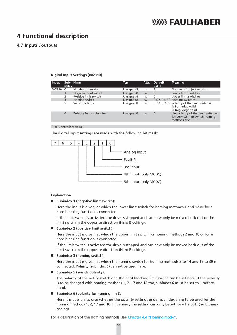
59
4 Functional description4.7 Inputs / outputs
Digital Input Settings (0x2310)
Index Sub-index
Name Typ Attr. Default value
Meaning
0x2310 0 Number of entries Unsigned8 ro 6 Number of object entries1 Negative limit switch Unsigned8 rw 0 Lower limit switches2 Positive limit switch Unsigned8 rw 0 Upper limit switches3 Homing switch Unsigned8 rw 0x07 / 0x1F *) Homing switches5 Switch polarity Unsigned8 rw 0x07 / 0x1F *) Polarity of the limit switches
1: Pos. edge valid0: Neg. edge valid
6 Polarity for homing limit Unsigned8 rw 0 Use polarity of the limit switches for DSP402 limit switch homing methods also
*) BL-Controller / MCDC
The digital input settings are made with the following bit mask:
7 6 5 4 3 2 1 0
Analog input
Fault-Pin
3rd input
4th input (only MCDC)
5th input (only MCDC)
Explanation
� Subindex 1 (negative limit switch):
Here the input is given, at which the lower limit switch for homing methods 1 and 17 or for a hard blocking function is connected.
If the limit switch is activated the drive is stopped and can now only be moved back out of the limit switch in the opposite direction (Hard Blocking).
� Subindex 2 (positive limit switch):
Here the input is given, at which the upper limit switch for homing methods 2 and 18 or for a hard blocking function is connected.
If the limit switch is activated the drive is stopped and can now only be moved back out of the limit switch in the opposite direction (Hard Blocking).
� Subindex 3 (homing switch):
Here the input is given, at which the homing switch for homing methods 3 to 14 and 19 to 30 is connected. Polarity (subindex 5) cannot be used here.
� Subindex 5 (switch polarity):
The polarity of the notify switch and the hard blocking limit switch can be set here. If the polarity is to be changed with homing methods 1, 2, 17 and 18 too, subindex 6 must be set to 1 before-hand.
� Subindex 6 (polarity for homing limit):
Here it is possible to give whether the polarity settings under subindex 5 are to be used for the homing methods 1, 2, 17 and 18. In general, the setting can only be set for all inputs (no bitmask coding).
For a description of the homing methods, see Chapter 4.4 “Homing mode”.

60
4 Functional description4.7 Inputs / outputs
The limit switch functions for the fault pin are only accepted if this is configured as reference input (fault pin function 4) (ensure you always save the setting with SAVE) via object 0x2315.01!
In the default configuration all inputs are configured as homing inputs. A homing switch can there-fore be connected at each input. However, it is recommended that only the homing input at which the reference switch is actually connected be given.
If a homing method is run without defining the necessary switches in 0x2310 beforehand the hom-ing run does not start!
4.7.2 Special functions of the fault pin
The error connection (fault pin) can be configured as input or output for different tasks using the fault pin settings object (0x2315):
Fault-Pin Settings (0x2315)
Index Sub-index
Name Typ Attr. Map Default value
Meaning
0x2315 0 Number of entries Unsigned8 ro 3 Number of object entries1 Fault-pin function Unsigned8 rw 0 Function of the fault pin
0 = Error output2 = Digital output4 = Reference input5 = Position output
3 Digital output status Unsigned8 rw / ro *) yes *) Change the state of the pin in the digital output function0 = Clear output1 = Set output2 = Toggle output
*) Dependent on the set fault-pin function (0x2315.01)
Fault-Pin Function (0x2315.01)
Value Function Description0 Error output Fault pin as error output2 Digital output Fault pin as digital output. The output is set to low level.4 Reference input Fault pin as reference or limit switch input5 Position output Fault pin as output for display of the condition: “target position reached".
In the function as output the connection is designed as an open collector; this means that when the output is set the connection is drawn to low level.
Fault pin as error outputIn the error output function the output is set as soon as an error occurs in the FAULHABER error register and the errout mask in object 0x2321 is set to 1 for the corresponding error (see also Chapter 4.8 “Error handling”).

61
4 Functional description4.7 Inputs / outputs
Additional settings
Delayed signalling
In order to hide the transient occurrence of errors, for example, during the acceleration phase, the error handling object (0x2322.01) can be used to set an error delay, which indicates how long an er-ror must be queued before it is displayed at the error output (see Chapter 4.8 “Error handling”). The error delay affects the errors: “Continuous over current”, “Deviation” and “Over voltage”.
Example:
Wait 2 seconds before displaying error:
� Error delay = 200 (object 0x2322.01)
Fault pin as digital outputIn the digital output function the fault pin can be used as a universal digital output. The digital out-put can be set or deleted via object 0x2315.03:
Digital Output Status (0x2315.03)
Value Function Description0 Clear output Set digital output to low level1 Set output Set digital output to high level2 Toggle output Switch to digital output
Fault pin as reference inputIn the reference input function the fault pin has the function of a digital input and can be used as a limit switch or homing switch according to object 0x2310 or can be used to connect the index pulse of an incremental encoder.
Fault pin as “Position reached” outputIn the position output function the output is set if the target position has been reached in profile position mode, according to the conditions in position window (0x6067) and position window time (0x6068). The output is reset with the next positioning start command.
NOTE Configure before applying a voltageIf a voltage is applied to the fault pin while it is not configured as an input the electronics can be damaged.
Configure the fault pin as an input first before applying external voltage!

62
4 Functional description4.7 Inputs / outputs
4.7.3 Query the input states
The state of the digital inputs can be queried via the digital input status object (0x2311), namely as direct input level (subindex 02) ore polarity evaluated (subindex 01) in accordance with the entry under 0x2310.05. The state is displayed according to the bit mask of object 0x2310 (see Chapter 4.7.1 “Limit switch connections and switching level”).
Digital Input Status (0x2311)
Index Sub-index
Name Typ Attr. Map Default value
Meaning
0x2311 0 Number of entries Unsigned8 ro 2 Number of object entries1 Input status Unsigned8 ro yes State of the digital inputs polarity
evaluated.2 Input level Unsigned8 ro yes State of the digital inputs (applied
level)
The voltage applied at the analog input and at the other inputs can be queried in millivolts or in digits via the analog input status object (0x2313) and analog input status raw object (0x2314). The analog input can therefore also supply a measurement signal for the higher-level control.
Analog Input Status (0x2313)
Index Sub-index
Name Typ Attr. Map Default value
Meaning
0x2313 0 Number of entries Unsigned8 ro 3 / 5 *) Number of object entries1 Inp. 1 ADC value Integer16 ro yes Voltage at input 1 in mV
(AnIn)3 Inp. 3 ADC value Integer16 ro yes Voltage at input 3in mV
(3rd In)4 Inp. 4 ADC value Integer16 ro yes Voltage at input 4 in mV
(only MCDC)5 Inp. 5 ADC value Integer16 ro yes Voltage at input 5 in mV
(only MCDC)
*) BL-Controller / MCDC
Analog Input Status Raw (0x2314)
Index Sub-index
Name Typ Attr. Map Default value
Meaning
0x2314 0 Number of entries Unsigned8 ro 8 Number of object entries1 Inp. 1 ADC value raw Integer16 ro yes Digital value at input 12 Inp. 2 ADC value raw Integer16 ro yes Digital value at input 23 Inp. 3 ADC value raw Integer16 ro yes Digital value at input 34 Inp. 4 ADC value raw Integer16 ro yes Digital value at input 45 Inp. 5 ADC value raw Integer16 ro yes Digital value at input 56 Inp. 6 ADC value raw Integer16 ro yes Digital value at input 67 Inp. 7 ADC value raw Integer16 ro yes Digital value at input 78 Inp. 8 ADC value raw Integer16 ro yes Digital value at input 8
This object can also be used to read out the current raw values of the internally used digital inputs.
NOTE The objects for querying the input states can be mapped in PDOs. The PDOs can then be queried cy-clically via SYNC or RTR. Automatic sending of a PDOs in the event of a state change is not possible, as PDOs can only be sent automatically if the statusword is changed.

63
4 Functional description
4.8 Error handling
FAULHABER fault register (0x2320)
Index Sub-index
Name Typ Attr. Default value
Meaning
0x2320 0 fault register Unsigned16 ro FAULHABER fault register
The FAULHABER error register contains, bit-coded, the last errors to occur.
The errors are coded as follows and can be masked by adding the required error types via the error mask object (0x2321):
Error-bit Error Description0x0001 Continuous over current Set continuous current limiting exceeded0x0002 Deviation Set maximum permissible speed deviation exceeded0x0004 Over voltage Overvoltage detected0x0008 Over temperature Maximum coil or MOSFET temperature exceeded0x0010 Flash memory error Memory error0x0040 CAN in error passive mode CAN controller in error passive mode0x0080 CAN overrun (objects lost) Overrun of the CAN input buffer0x0100 Life guard or heartbeat error CAN monitoring error0x0200 Recovered from bus off Exit CAN bus error "Bus off"0x0800 Conversion overflow Computing overflow0x1000 Internal software Internal software error0x2000 PDO length exceeded PDO length too long, but is processed0x4000 PDO not processed due to length
errorPDO length too short, cannot be processed
Each of these errors also corresponds to an emergency error code (see Chapter 3.4 “Emergency ob-ject (error message)”).
Error Mask (0x2321)
Index Sub-index
Name Typ Attr. Default value
Meaning
0x2321 0 Number of entries Unsigned8 ro 3 Number of object entries1 Emergency mask Unsigned16 rw 0xFFFF Errors which trigger an emergency
telegram2 Fault mask Unsigned16 rw 0 Errors which are treated as DSP402
faults and affect the state machine (fault state)
3 Errout mask Unsigned16 rw 0x00FF Errors which set the error output
The error mask describes the handling of internal errors according to the coding given above.
NOTE On setting the fault mask (subindex 2) the corresponding bits are also copied into the emergency mask (subindex 1).
NOTE Set subindex 2 of object 0x2321 to 0x0001, in order to switch off the drive in the event of overcur-rent and to set it in the fault state. A value of 0x0101 also switches off the drive in the event of a CAN lifeguard or heartbeat error.
NOTE Set subindex 3 of object 0x2321 to 0 if the error output (fault pin) is not display any errors or to 0xFFFF if all errors (including CAN errors) are to be displayed.

64
4 Functional description4.8 Error handling
The error handling object (0x2322) can be used to make additional error processing settings.
Error delay: Error delay time, which specifies how long one of the following errors has to be queued before it is reported: Continuous overcurrent, deviation, overvoltage.
Deviation: Largest, in terms of the amount, permissible deviation of the actual velocity from the target velocity. If this value is exceeded it is reported after the error delay time has expired.
Error Handling (0x2322)
Index Sub-index
Name Typ Attr. Default value
Meaning
0x2322 0 Number of entries Unsigned8 ro 2 Number of object entries1 Error delay Unsigned16 rw 200 Error delay time in 1/100 s
Value = 0 … 65 5352 Deviation Unsigned16 rw 30 000 Permissible velocity deviation
in rpmValue = 0 … 30 000
4.8.1 Query of the device state
The device status object (0x2323) is available for monitoring the current device status; it can be used to query the current temperatures and temperature thresholds in °C.
Device Status (0x2323)
Index Sub-index
Name Typ Attr. Default value
Meaning
0x2323 0 Number of entries Unsigned8 ro 4 Number of object entries1 Housing temperature Unsigned16 ro Housing temperature2 Internal temperature Unsigned16 ro Coil or MOSFET temperature resist-
ance3 Max. temperature limit Unsigned16 ro Upper temperature threshold4 Min. temperature limit Unsigned16 ro Lower temperature threshold
The values of the upper and lower temperature threshold show the switching on and switching off threshold of the integrated overtemperature protection (see Chapter 4.9.4 “Overtemperature pro-tection”).

65
4 Functional description
4.9 Technical information
4.9.1 Ramp generator
In all modes the set-point is controlled by the ramp generator.
Basic ramp generator function
t
t
t
a [1/s²]
v [rpm]
Pos
profile acceleration
profile deceleration
profile velocity
This can be used to separately set the parameters for maximum acceleration (profile acceleration), maximum delay (profile deceleration) and maximum speed (profile velocity) for specific applications.
Basic settings
Index Sub-index
Name Type Attr. Default value
Meaning
0x6081 0 Profile velocity Unsigned32 rw *) Maximum velocity in 1/s²Value = 0 … 30 000
0x6083 0 Profile acceleration Unsigned32 rw 30 000 Maximum acceleration in 1/s²Value = 0 … 30 000
0x6084 0 Profile deceleration Unsigned32 rw 30 000 Maximum deceleration in 1/s²Value = 0 … 30 000
*) Dependent on the factory configuration of the motion controller

66
4 Functional description4.9 Technical information
Ramp generator in profile velocity mode
Intervention of the ramp generator in velocity mode
Target velocity
Downstream of the ramp generator
t
t
t
a [1/s²]
v [rpm]
Pos
profile acceleration
profile deceleration
profile velocity
In velocity mode the ramp generator acts like a filter on the target velocity. The target value is limited to the profile velocity value and target velocity value changes are limited according to the profile acceleration and profile deceleration.

67
4 Functional description4.9 Technical information
Ramp generator in profile position mode
Intervention of the ramp generator in positioning mode
Target Position
Downstream of the ramp generator
t
t
t
a [1/s²]
v [rpm]
Pos
profile acceleration
profile deceleration
profile velocity
In positioning mode a preset speed is determined by the position controller from the difference between the target position and actual position.
In the ramp generator, the preset speed output by the position controller is limited to the profile velocity value and accelerations are limited according to the acceleration ramp (profile acceleration).
In positioning mode the deceleration process is not extended as, before reaching the limit position, the speed has to be reduced so that the target position can be reached without overshooting.
According to the equation of motion:
2a s = v2 vmax = 2a s
a: acceleration [m/s2]
v: velocity [m/s]
s: remaining distance [m]
the maximum speed nmax must be limited proportional to the remaining distance.
The allowable delay, or rather the technically possible delay depending on the motor and inertia of the load, is set here using the parameter profile deceleration.

68
4 Functional description4.9 Technical information
4.9.2 Sinus commutation
The outstanding feature of FAULHABER motion controllers for brushless motors is their so-called sinus commutation. This means that the specified rotating field is always ideally positioned relative to the rotor. As a result, torque fluctuations can be reduced to a minimum, even at very low speeds. In addition, the motor runs particularly quietly.
The sinus commutation is further enhanced by so-called flat-top modulation, which enables more modulation. As a result, higher no-load speeds are possible.
The parameter pure sinus commutation in the object general settings can even be used to set the system so that the sinus commutation switches to block commutation in the upper speed range. This full modulation enables the complete speed range of the motor to be utilised.
General Settings (0x2338)Index Sub-
indexName Typ Attr. Default
valueMeaning
0x2338 0 Number of entries Unsigned8 ro 3 Number of object entries1 Pure sinus commutation Unsigned16 rw 1 0 = full control
1 = limiting to sine-wave form(not MCDC)
2 Activate position limits in velocity mode
Unsigned16 rw 0 1 = use set positioning range limits, including in velocity mode
3 Activate position limits in position mode
Unsigned16 rw 1 0 = no range limits in positioning mode
4.9.3 Current controller and I²t current limitation
Intervention of the current limiting controller
Gat
e D
rive
rG
ate
Dri
ver
-
-
Ramp generator n controller
Higher-level controller
Peak current
Continuous current
3
PI
Iact.
Imax
Commutation velocity calculation
I2t limit current calculation
BL Motor
DC Motor
Hall IE
Gat
e d
rive
r
The FAULHABER Motion Controllers are equipped with an integral current controller, which enables torque limitation.
The current controller operates as a limitation controller. Depending on the previous loading, the I²t current limitation limits to the allowable peak current or continuous current. As soon as the motor current exceeds the currently allowed maximum value the current controller limits the voltage.
Due to its design as a current limiting controller, current control in the thermally relaxed state has no effect on the dynamic of the velocity control. The time response of this limitation can be adjusted using the parameter CI.
The default values for CI limit the current to the allowable value after around 5ms.
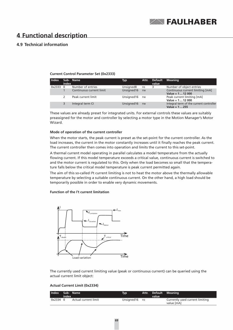
69
4 Functional description4.9 Technical information
Current Control Parameter Set (0x2333)
Index Sub-index
Name Typ Attr. Default value
Meaning
0x2333 0 Number of entries Unsigned8 ro 3 Number of object entries1 Continuous current limit Unsigned16 rw Continuous current limiting [mA]
Value = 1 … 12 0002 Peak current limit Unsigned16 rw Peak current limiting [mA]
Value = 1 … 12 0003 Integral term CI Unsigned16 rw Integral term of the current controller
Value = 1 … 255
These values are already preset for integrated units. For external controls these values are suitably preassigned for the motor and controller by selecting a motor type in the Motion Manager’s Motor Wizard.
Mode of operation of the current controller
When the motor starts, the peak current is preset as the set-point for the current controller. As the load increases, the current in the motor constantly increases until it finally reaches the peak current. The current controller then comes into operation and limits the current to this set-point.
A thermal current model operating in parallel calculates a model temperature from the actually flowing current. If this model temperature exceeds a critical value, continuous current is switched to and the motor current is regulated to this. Only when the load becomes so small that the tempera-ture falls below the critical model temperature is peak current permitted again.
The aim of this so-called I²t current limiting is not to heat the motor above the thermally allowable temperature by selecting a suitable continuous current. On the other hand, a high load should be temporarily possible in order to enable very dynamic movements.
Function of the I²t current limitation
max.
Limitation
Duration
Motor
criticalModel TimeTT
I
I
I
I
I
TimeLoad variation
The currently used current limiting value (peak or continuous current) can be queried using the actual current limit object:
Actual Current Limit (0x2334)
Index Sub-index
Name Typ Attr. Default value
Meaning
0x2334 0 Actual current limit Unsigned16 ro Currently used current limiting value [mA]

70
4 Functional description4.9 Technical information
4.9.4 Overtemperature protection
If the MOSFET temperature of the external controllers or the coil temperature of the drives with integrated controller exceeds a preset limit value more than one second, the motor is switched off. The FAULHABER error mask (object 0x2321) can be used to set the further response to an overtem-perature error (EMCY, fault state or error output).
� The following conditions must be fulfilled in order to reactivate the motor:
� Temperature below the preset limit value
� Target velocity set to 0 rpm
� Actual motor speed less than 50 rpm
NOTE Determining the coil temperatureThe housing temperature is measured and the power loss concluded from the current measurement. The MOSFET or coil temperature is calculated from these values via a thermal model. In most applica-tions, this method represents a thermal motor protection device.
4.9.5 Under-voltage monitoring
If the supply voltage falls below the lower voltage threshold, the power stage is switched off. The Motion Controller remains active. When the voltage returns within the permissible range, the power stage is switched on again immediately.
4.9.6 Overvoltage regulation
If the motor is operated as a generator, it produces energy. Usually power supply units are not able to feed this energy back into the power line. For this reason, the supply voltage at the motor in-creases, and depending on the speed, the allowable maximum voltage may be exceeded.
In order to avoid irreparable damage to components, FAULHABER motion controllers for brushless motors contain a controller which adjusts the rotor displacement angle if a limit voltage (32 V) is ex-ceeded. Motion controllers for DC motors contain a ballast circuit which is activated if a limit voltage (32 V) is exceeded. As a result, the energy generated in the motor is converted, and the voltage of the electronics remains limited to 32 V. This method protects the drive during generating operation and rapid braking.
4.9.7 Setting the controller parameters for velocity and position controller
The preset controller parameters must be optimised in order to optimally adjust the controller to the respective application.
NOTE Controller sampling rateThe digital controller operates with a sampling rate of 200 μs, with 100 μs for MCDC and MCBL-AES. When needed the sampling rate can be increased up to 2 ms via the parameter sampling rate (object 0x2330.01).

71
4 Functional description4.9 Technical information
Default behaviour:
Without further settings, the gain set in the proportional term parameter POR is effective for the velocity controller in profile velocity mode.
In profile position mode the gain set via the proportional term parameter POR is increased within the target corridor by the value of the derivative term parameter PD. This enables faster adjustment to the stoppage in the target position without having to over-stimulate the controller during the transition phenomena. To this end, the parameter PD must be set carefully and should typically be a maximum of 50% of the base value POR; otherwise there is a risk of instability.
The following controller parameters are available:
Filter Settings (0x2330)
Index Sub-index
Name Typ Attr. Default value
Meaning
0x2330 0 Number of entries Unsigned8 ro 2 Number of object entries1 Sampling rate Unsigned16 rw 1 Sampling rate factor
Value = 1 … 202 Gain scheduling Unsigned16 rw 0 1 = Reduced controller gain within
the target corridor during positioning
Gain scheduling:
If gain scheduling (0x2330.02) is activated the controller gain POR is reduced successively in position-ing mode, as soon as the drive is located within the target corridor (0x6067). This enables a much “gentler” stoppage to be achieved in the target position. As soon as the drive leaves the target cor-ridor, POR is immediately increased back to the set value.
Regelabweichung
PV Mode: Proportional term PORPP Mode: Proportional term POR + derivative term PD
PP Mode + gain schedule: Reduced proportional term POR
Reg
lerv
erst
ärku
ng
target window
NOTEThe “Gain scheduling” function only becomes active for sampling rates with a factor larger than 3 (sampling rate > 3).

72
4 Functional description4.9 Technical information
Velocity Control Parameter Set (0x2331)
Index Sub-index
Name Typ Attr. Default value
Meaning
0x2331 0 Number of entries Unsigned8 ro 2 Number of object entries1 Proportional term POR Unsigned16 rw *) Proportional gain of the velocity
controllerValue = 1 … 255
2 Integral term I Unsigned16 rw *) Integral term of the velocity con-trollerValue = 1 … 255
*) Dependent on the factory configuration of the motion controller
Position Control Parameter Set (0x2332)
Index Sub-index
Name Typ Attr. Default value
Meaning
0x2332 0 Number of entries Unsigned8 ro 2 Number of object entries1 Proportional term PP Unsigned16 rw *) Proportional gain of the position
controllerValue = 1 … 255
2 Derivative term PD Unsigned16 rw *) Differential term of the velocity controllerValue = 1 … 255
*) Dependent on the factory configuration of the motion controller
In the case of integrated units these values are already preset, however, they can be adjusted to the driving load using the Motion Manager’s Motor Wizard. These values are suitably preassigned for external controls by selecting a motor type in the Motion Manager’s Motor Wizard.
The controller tuning Wizard in Motion Manager can be used to further adjust several controller parameters, in order to optimally adjust the controller to the respective application.
Possible procedure
It is recommended that you begin with the default settings of the Motor Wizard and then further optimise the velocity controller first and then the position controller.
1.) Optimise velocity controller:
Use, for example, the controller tuning Wizard to make velocity jumps between 1/3 and 2/3 of the maximum velocity and at the same time increase the controller gain POR gradually, until the con-troller becomes unstable. The controller gain must then be reduced again until reliable stability exists. Under certain circumstances it may be necessary to optimise the integral term I accordingly.
2.) Optimise position controller:
Specify appropriate motion profiles for the application, e.g. using the controller tuning Wizard. If the system does not function stably with these settings, stability can be achieved by reducing the I term of the velocity controller or reducing the P term of the position controller. Then increase the P term of the position controller gradually up to the system’s stability limit. The stability can then be restored, either by increasing the D term of the position controller or by reducing the I term of the velocity controller.

73
5 Commissioning
The drive unit must be connected to a PC via a CAN adapter or a host control with CAN interface in order to make the basic settings for commissioning.
NOTE Connection of the CAN interface is described in the technical manual. For the communication setup, ensure that the same transfer rate is set for all nodes (see Chapter 2.2 “Set node number and baud rate”) and the terminating resistances are used!
FAULHABER Motion Manager provides a convenient device configuration option using graphic dia-logues.
The configuration can also be carried out using your own programming or other CANopen configu-ration tools.
5.1 Node number and baud rate
The node address and transfer rate are set using the network in accordance with the LSS protocol according to CiA DSP305 V1.1 (layer setting services and protocol).
A configuration tool which supports the LSS protocol is therefore required for the setting, e.g. FAUL-HABER Motion Manager.
The configuration tool is the LSS master, and the drives act as LSS slaves.
LSS slaves can be configured in two ways:
1. “switch mode global” switches all connected LSS slaves to configuration mode. However, only one LSS slave may be connected to set the baud rate and node ID.
2. “switch mode selective” switches precisely one LSS slave in the network to configuration mode. For this, the vendor ID, product code, revision number and serial number of the node to be ad-dressed must be known.
Guide
Node number and baud rate Page 73
Basic settings Page 75
Configuration using the Motion Manager Page 76
Page 83
Diagnosis Page 83

74
5 Commissioning5.1 Node number and baud rate
The following baud rates (bit timing parameters) can be set:
Baud rate Index1 000 kbit/s 0
800 kbit/s 1500 kbit/s 2250 kbit/s 3125 kbit/s 450 kbit/s 620 kbit/s 710 kbit/s 8
In addition, index 0xFF can be used to activate automatic baud rate detection.
The following node numbers can be set:
1 … 127.
Node ID 255 (0xFF) indicates that the node has not yet been configured, which causes the node to retain in LSS-Init status after it is switched on until a valid node number is transferred to it. Only then is the NMT initialisation continued.
NOTE At the transition from node ID 255 (unconfigured) to a valid node number all communication set-tings are set to their default values. The COB IDs of the PDOs and the EMCY objects are then reset according to the predefined connection set (see Chapter 3.6 “NMT (network management)”
The LSS protocol also supports the reading of of LSS addresses, consisting of the vendor ID, product code, revision number and serial number of connected units and reading out of the set node ID.
Identifiers 0x7E5 (from the master) and 0x7E4 (from the slave), on which the protocol is worked through, are used for LSS communication.
Following configuration, the set parameters are backed up in the flash memory, so that they are available again after switching off and on.
FAULHABER controllers use vendor ID, product code and serial number only to activate the “switch mode selective”. 0.0 can always be transferred for the revision number, as this value is ignored in the protocol.
Vendor ID: 327
Product code: 3150
Please refer to the CiA document DSP 305 for a detailed description of the LSS protocol.
If automatic baud rate detection is activated, the drive can be used in a network with any trans-mission rate in accordance with the table above and after 3 message frames on the bus line at the latests, the baud rate of the network is detected and the drive has adjusted itself to it. Here it must be noted that the initial message frames cannot be processed and booting takes a little longer.

75
5 Commissioning
5.2 Basic settings
In the case of external motion controllers, several basic settings have to be made during the initial start-up to adjust the controller to the connected motor.
If drive units are integrated, these basic settings are made in the factory so it is only necessary to adjust to the respective application.
CAUTION! Risk of destruction!Failure to observe these basic settings can result in destruction of components!
f The basic settings described in the following must be noted and observed
The following basic settings must be made for external motion controllers:
� Motor type or motor data of the connected motor
� Resolution of an external encoder, if used
� Current limitation values, adjusted to the motor type and application
� Controller parameters, adjusted to the motor type and application
In addition, FAULHABER Motion Manager can be used to synchronise the hall sensor signals of BL motors for smooth start-up and optimisation of the phase angle for the best efficiency.
The configuration must then be adjusted to the respective application for all motion controllers (in-tegrated and external). In particular, the following basic settings are important:
� Operating mode
� Current limiting values
� Controller parameters
� Function of the digital inputs/outputs
Warning! Risk of destructionIf using the Fault Pin as input, the desired function must be programmed before applying external voltage!
Configuration of these parameters with the help of the FAULHABER Motion Manager is explained in greater detail in the following chapter.

76
5 Commissioning
5.3 Configuration using the Motion Manager
“FAULHABER Motion Manager” PC software provides a simple option for configuring the drive unit
and for performing initial tests and optimisation.
The software is available for Microsoft Windows and can be downloaded free of charge from the
FAULHABER internet site: www.faulhaber.com.
Motion control systems with electronics built onto the motor are already pre-parameterised in the factory.
Motion controllers with an externally connected motor must be equipped with current limitation values suitable for the motor and suitable controller parameters before being started up.
The motor selection Wizard is available for selecting the motor and the suitable basic parameters.
Other settings, e.g. for the function of the fault pin, can be made under the “configuration – drive functions” menu item, where a convenient dialog is provided (see Chapter 5.3.3 “Drive configura-tion”). The configuration dialog is also available for direct access in the wizard bar of the Motion Manager.
A tuning wizard, with which the controller parameters of the speed and positioning controller can be adjusted to the application, is also provided.

77
5 Commissioning5.3 Configuration using the Motion Manager
5.3.1 Connection setting
If no drive nodes are found when the Motion Manager is started, a connection wizard appears. In the first step, the “Motion Controller with CAN-interface” product group must be selected. The con-nection wizard can also be started at any time via the wizard bar.
Connection wizard (Step 1: Selection of the controller)
In the second step, the CAN interface used and, if applicable, the baud rate can be set. Information on the supported CAN interfaces is given in the instruction manual of the Motion Manager or you can contact FAULHABER for information.
The interface found by the driver must then be explicitly adopted again as a once-off action.
Connection wizard (Step 2: Selection of Interface)
Devices which are already set to a baud rate are then found by the Motion Manager and are dis-played in the Node Explorer.
Devices which have not yet been configured can be assigned a node number and baud rate in a further step.

78
5 Commissioning5.3 Configuration using the Motion Manager
5.3.2 Motor selection
External motion controllers must be adjusted to the connected motor.
The Motor Wizard is provided for this purpose; it can be opened via the Wizard bar of the Motion Manager.
After selecting the required FAULHABER motor from a list and setting the sensor type used, as well as entering an inertia factor for the load to be operated, in addition to the motor and current limit-ing values, suitable controller parameters are also determined and transferred to the drive.
Refer to the Motion Manager instruction manual for details of how to use the Motor Wizard.
5.3.3 Drive configuration
The Motor Wizard has already set sensible default settings for the motor/sensor combination se-lected.
A configuration dialog with several pages for further drive configuration and adjustment to the required application is available in the Motion Manager’s Wizard bar or under the menu item: “Con-figuration – Drive functions... “.
The settings of the register pages are not transferred to the drive until the “Send” button is pressed. The current state of the drive is also read back and the dialog is updated accordingly. At the same time, invalid combinations of settings are corrected, as they will not be accepted by the drive.
The settings are permanently saved in the drive using the “SAVE” button.
NOTE In addition, settings can be made using the CANopen object browser (Menu: "CAN – CANopen Object dictionary – CANopen object browser…“), which shows the whole object dictionary. The PDO mapping dialog can be used to adjust the PDO data layout to the required application.
Basic settingsWithin the scope of the commissioning, the following settings must be made in the Basic Settings tab:
� DSP402 mode
� Positioning range limits
� Velocity range limit
� Encoder settings
� Commutation settings for BL motors
DSP402 modes
It is possible to switch between Profile Position Mode (position control), Profile Velocity Mode (veloc-ity control) and Homing Mode (reference run) modes.
Positioning range limits
The movement range can be monitored and limited in various operating modes. The limits of this movement rage can be given here in unit of the actual position. Object 0x2338.02 of the general set-tings can be used to activate the range limits for profile velocity mode too. By default the monitor-ing is only active in profile position mode and in the homing modes.

79
5 Commissioning5.3 Configuration using the Motion Manager
Encoder type and optimisation
If an incremental encoder attached to the motor is to be evaluated its effective resolution must be given for 4 edge evaluation. If using the internal encoder, no further inputs are necessary.
A button, with which the Optimisation Wizard can be started, is available for adjusting Hall sensor signals and phase angles to the connected motor for externally connected BL motors with analog Hall sensors.
NOTE Ensure that the motor can freely rotate before starting the encoder optimisation.
Commutation setting for BL motors
By default the Motion Controller for BL motors uses pure sinus commutation.
This means the motor runs with the lowest possible losses and noise.
Alternatively, at higher velocities it is possible to use the object 0x2338.01 of the general settings to also allow overriding of the output signals similar to block commutation. The whole velocity range of the drive can be used as a result.
NOTE On changing between pure sinus commutation and operation with block commutation in the upper velocity range the controller gain is also increased accordingly.
Factor groupConversion factors of internal user-defined position values can be given in the “Factor Group” tab.
Conversion factors for position values
Most position details are preset and displayed in user units. The objects of the factor group are avail-able for converting internal units into user units.
Factors for a given gear reduction and a feed rate can be given here.
The conversion factor for position values is determined from these depending on the respective encoder resolution.
Controller settingsChanges to the default set controller and current limiting parameters can be made in the “Velocity Controller” and “Position Controller” tabs of the drive configuration dialog.
In addition, under the “Configuration – Controller Parameters...” menu item, there is another dialog in which the parameters can be changed online and the result can be observed directly or can be recorded using die trace function in Motion Manager.

80
5 Commissioning5.3 Configuration using the Motion Manager
Current controller
The continuous current parameter can be used to give the thermally allowable continuous current for the application.
Motors and the Motion Controller can be overloaded within certain limits. Therefore, higher currents can also be allowed for dynamic processes. The maximum peak current value is given via the peak current parameter.
Depending on the drive’s load, the internal current monitoring limits the output current to the peak current or the allowable continuous current.
NOTE Risk of irreparable damage!The continuous current value given should never be above the thermally allowable continuous cur-rent of the motor according to its data sheet.
The peak current value given must never be above the maximum peak output current of the existing electronics.
The current controller of the Motion Controller operates as a current limiting controller and there-fore in an unlimited case has no effect on the dynamics of the velocity control. The speed of the limiting can be set using the parameter CI. If using the default values for your motor, the current is limited to the allowable value after around 5ms.
If a FAULHABER motor was selected via the Motor Wizard, parameters are already set here with which the motor can be operated safely.
Further details are given in Chapter 4.9.3 “Current controller and I²t current limitation”
Velocity controller
The velocity controller is designed as a PI controller. The sampling rate can be set as multiples of the basic sampling rate of the drive, the proportional gain POR and the integral component I.
If a FAULHABER motor was selected via the Motor Wizard, parameters are already set here with which the motor can be operated safely.
If the motor is exposed to additional loads, the inertia of the load must be compensated for by a higher proportional term and if necessary slower sampling; in most applications the integral term can remain unchanged.
Further notes on setting are given in Chapter “The following conditions must be fulfilled in order to reactivate the motor:”
Ramp generator
The ramp generator limits the velocity change at the input of the velocity controller via the profile acceleration and profile deceleration parameters and the maximum default speed profile velocity.
The profile acceleration and profile velocity parameters can be freely selected depending on the ap-plication; the profile deceleration parameter is used to specify the deceleration behaviour in posi-tioning mode. For large loads, the deceleration ramp must be limited using the profile deceleration parameter, in order to achieve dead beat (overshoot-free) run-in in the target position.
Further notes on setting are given in Chapter 4.9.1 “Ramp generator”

81
5 Commissioning5.3 Configuration using the Motion Manager
Position controller
The position controller is designed as a proportional controller. An additional D term also acts, but only within the target corridor.
The proportional term uses the position deviation in increments to calculate the maximum default velocity for the secondary velocity controller. The ramp generator is used to additionally limit the ac-celeration and maximum velocity.
Dead beat run-in in the target position can be preferentially achieved by adjusting the deceleration ramp to the load. For a well-attenuated transient condition in the limit position, the parameter PP must be reduced proportionally to the load inertia.
Further notes on setting are given in Chapter “The following conditions must be fulfilled in order to reactivate the motor:”
Target corridor
The position window and position window time parameters define a range about the target posi-tion and a dwell time within this range, until the “Target Reached” bit is set in the statusword. If the transmission type is set to 255 for the PDO that contains the statusword (default setting), the target position is signalled via an asynchronously sent PDO. Within this corridor the D term of the position controller is active and the ramp generator is inactive.
Error handlingIn the “Error handling” tab of the drive configuration dialog it is possible to set how the Motion Controller is to respond to certain fault events.
Basically, errors can be signalled via an emergency telegram and via the error output. It is also pos-sible to set that the drive is to switch to DSP402 error state if certain errors occur.
The error delay parameter specifies how long an overcurrent, overvoltage or velocity deviation error has to be queued before it is signalled.
Maximum permissible velocity deviation
In the error handling object the deviation parameter can be used to specify a maximum permissible velocity deviation for the velocity controller.
If this barrier is exceeded for longer than the time set with the error delay parameter, an error is sig-nalled via the fault pin or via a CANopen emergency message, depending on the setting in the error mask object.
Inputs/outputs and homingThe “Inputs/outputs and Homing” tab of the drive configuration dialog can be used to specify the function of the digital inputs and outputs and to define the homing settings.
Input level and edge
The switching thresholds of the digital inputs are either directly 5V TTL compatible or are adjusted to the switching level of 24V PCS outputs. The setting is made via the input threshold level parameter.
Precise details of the thresholds are given in the drive’s data sheet.

82
5 Commissioning5.3 Configuration using the Motion Manager
Function of the fault pin
The fault pin can be used both as an input and as an output. The required function can be selected using the “Fault Pin Function” radiobuttons.
NOTE Do not connect 24V to the fault pin, if the fault pin is configured as a digital output (ERROUT / DIGOUT)!
For the default function as a fault output, the delay time can be specified via the error delay param-eter in the “Error Handling” tab in order to suppress the response, e.g. to individual short overcur-rent pulses.
In the “Position Output” function the output displays reaching of the target position as a digital signal (low means target position is reached).
In the “Digital Output” function the output can be set and deleted from a higher-level control via the digital output status parameter (object 0x2315.03).
In the “Reference Input” function the fault pin can be used as a reference input for connecting a homing or reference switch
Function of the digital inputs
The displayed input matrix can be used to set use of the available digital inputs:
� Limit switches are limiting switches that when activated block the respective movement direction. The polarity bit can be used to set whether the positive or the negative edge is to be valid for the activation.
� Homing switches are reference switches for resetting the position to zero with certain homing methods. Here the polarity is predefined by the selected homing method.
� Limit switches can also be used like homing switches to reset the position to zero with certain homing methods. Here the polarity is also predefined by the selected homing method. However, if, in deviation from DSP402, the polarity is to be changed, this can be set using the polarity bit, provided the “Use polarity for homing mode limit switches” function is activated.

83
5 Commissioning
5.4 Data set management
Save parameters
The settings of a drive can be saved as a backup or as a file for configuration of other drives.
The Motion Manager provides the option of reading out the current drive configuration via the CANopen object browser and saving it as an XDC file (XML device configuration file).
Transfer parameters to the drive
In the Motion Manager, previously saved XDC files can be opened in the CANopen object browser where they can be edited if necessary and transferred to the drive.
NOTE Run the SAVE command to permanently save a transferred parameter set in the drive.
5.5 Diagnosis
5.5.1 Status display
The status display is used for continuous checking of the main operating states.
Internal states, error flags and the state of the digital inputs are signalled. In addition, the internally measured housing temperature, the statusword and further actual values are displayed here.
The display is updated by Motion Manager via cyclical querying of the state data.
Internal states
Partially autonomous states of the Motion Controller are displayed. These are the error flags, the housing temperature and the states of the digital inputs.
The current limiting flag is set if the maximum current has been set to continuous current by the i²t monitoring.
Device state (DSP402)
The individual bits of the DSP402 statusword and the current actual position and actual velocity are displayed.
5.5.2 Trace function
Motion Manager provides a trace function as an additional diagnosis tool with which the internal parameters can be graphically recorded. This enables the dynamic behaviour of the drive to be moni-tored, which is useful, e.g. for optimisation of the controller parameters.

84
6 Parameter description
6.1 Communication objects according to CiA 301
Device Type
Index Subindex Name Type Attr. Map Default value Meaning0x1000 0 Device type Unsigned32 ro 0x00420192 Specification of the device
type
Contains information on the device type, divided into two 16-bit fields:
byte: MSB LSB
Additional information Device profile number
Device profile number = 0x192 (402d) Additional information = 0x42 (Servo drive, type-specific PDO mapping)
Error Register
Index Subindex Name Type Attr. Map Default value Meaning0x1001 0 Error register Unsigned8 ro yes Error register
The error register contains, bit coded, the types of errors that have most recently occurred. For a description of the error register see Chapter 3.4 “Emergency object (error message)”.
Pre-defined Error Field (error memory)
Index Subindex Name Type Attr. Map Default value Meaning0x1003 0 Number of errors Unsigned8 rw Number of stored errors
1 Standard error field Unsigned32 ro Last error2 Standard error field Unsigned32 ro Error before last
The error memory contains the coding of the last error to occur. The standard error field is divided into two 16-bit fields:
byte: MSB LSB
Error register Error code
The meaning of the individual error codes is described in Chapter 3.4 “Emergency object (error mes-sage)”.
The error memory is deleted by writing “0” on subindex 0.
COB ID SYNC
Index Subindex Name Type Attr. Map Default value Meaning0x1005 0 COB ID SYNC Unsigned32 rw 0x80 CAN object identifier of the
SYNC object
Manufacturer Device Name
Index Subindex Name Type Attr. Map Default value Meaning0x1008 0 Manufacturer device name Vis-String const Device name
Use the segmented SDO protocol to read out the device name, as it can be larger than 4 bytes.

85
6 Parameter description6.1 Communication objects according to CiA 301
Manufacturer Hardware Version
Index Subindex Name Type Attr. Default value Meaning0x1009 0 Manufacturer hardware
versionVis-String const Hardware Version
Use the segmented SDO protocol to read out the hardware version, as it can be larger than 4 bytes.
Manufacturer Software Version
Index Subindex Name Type Attr. Default value Meaning0x100A 0 Manufacturer software ver-
sionVis-String const Software Version
Use the segmented SDO protocol to read out the software version, as it can be larger than 4 bytes.
Guard Time
Index Subindex Name Type Attr. Default value Meaning0x100C 0 Guard time Unsigned16 rw 0 Monitoring time for
Life Guarding
Specification of the Guard Time in milliseconds, 0 switches off the monitoring.
Life Time Factor
Index Subindex Name Type Attr. Default value Meaning0x100D 0 Life time factor Unsigned8 rw 0 Time factor for Life Guarding
The life time factor multiplied by the guard time gives the life time for the node guarding protocol (see Chapter 3.6 “NMT (network management)”). 0 switches off life guarding.
Store Parameters
Index Subindex Name Type Attr. Default value Meaning0x1010 0 Number of entries Unsigned8 ro 3 Number of object entries
1 Save all parameters Unsigned32 rw 1 Saves all parameters2 Save communication param-
etersUnsigned32 rw 1 Save communication param-
eters only3 Save application parameters Unsigned32 rw 1 Save application parameters
only
This object saves configuration parameters in the non-volatile flash memory. Read access provides information about the storage options.
The storage process is triggered by writing the “save” signature on the relevant subindex:
Signature MSB LSB
ISO 8859 ("ASCII") e v a s
hex 65h 76h 61h 73h
CAUTION! Flash memoryThe Flash memory is designed for 10 000 write cycles. If this command is executed more than 10 000 times, the function of the Flash memory can no longer be guaranteed.
f Do not execute command more than 10 000 times.

86
6 Parameter description6.1 Communication objects according to CiA 301
Restore Default Parameters
Index Subindex Name Type Attr. Default value Meaning0x1011 0 Number of entries Unsigned8 ro 6 Number of object entries
1 Restore all factory parameters Unsigned32 rw 1 Factory settings2 Restore factory communica-
tion parametersUnsigned32 rw 1
3 Restore default application parameters
Unsigned32 rw 1
4 Restore all saved parameters Unsigned32 rw 1 Last saved settings5 Restore saved communication
parametersUnsigned32 rw 1
6 Restore saved application parameters
Unsigned32 rw 1
This object loads default configuration parameters (status on delivery or last saved status).
Read access provides information about the restore options.
The restore process is triggered by writing the “load” signature on the relevant subindex:
Signature MSB LSB
ISO 8 859 („ASCII“) d a o l
hex 64h 61h 6Fh 6Ch
If the default parameters are to be finally saved, a save command must be executed after restoring.
NOTEThe as-delivered state (factory configuration) can only be loaded if the drive is switched off (switch on disabled)!
COB ID Emergency Message
Index Subindex Name Type Attr. Default value Meaning0x1014 0 COB ID EMCY Unsigned32 rw 0x80 + Node ID CAN object identifier of the
Emergency Object
Consumer Heartbeat Time
Index Subindex Name Typ Attr. Default value Meaning0x1016 0 Number of entries Unsigned8 ro 1 Number of object entries
1 Consumer heartbeat time Unsigned32 rw 0 Heartbeat monitoring time
The value of the consumer heartbeat time is divided into 3 blocks:
� Bits 0 … 15 contain the consumer heartbeat time in milliseconds
� Bits 16 … 23 contain the node number to which the heartbeat message is to be sent (master node ID)
� Bits 24 … 31 are unused (reserved).
At value 0 the consumer heartbeat function is deactivated.
Producer Heartbeat Time
Index Subindex Name Typ Attr. Default value Meaning0x1017 0 Producer heartbeat time Unsigned16 rw 0 Heartbeat send time interval
Contains the producer heartbeat time interval in milliseconds. At value 0 the producer heartbeat function is deactivated.

87
6 Parameter description6.1 Communication objects according to CiA 301
Identity Object
Index Subindex Name Type Attr. Default value Meaning0x1018 0 Number of entries Unsigned8 ro 4 Number of object entries
1 Vendor ID Unsigned32 ro 327 Manufacturer ID number(FAULHABER: 327)
2 Product code Unsigned32 ro 3 150 Product ID number3 Revision number Unsigned32 ro Version number4 Serial number Unsigned32 ro Serial number
Error Behaviour
Index Subindex Name Typ Attr. Default value Meaning0x1029 0 Number of entries Unsigned8 ro 1 Number of object entries
1 Communication error Unsigned8 rw 0 Behaviour in case of commu-nication errors0 = pre-operational state1 = no state change2 = Stopped state
By default, in the event of fatal communication errors the FAULHABER Motion Controllers switch to the NMT “Pre-Operational”. If another behaviour is required it can be set using subindex 1 of this object.
Server SDO Parameter
Index Subindex Name Type Attr. Default value Meaning0x1200 0 number of entries Unsigned8 ro 2 Number of object entries
1 COB ID client to server (rx) Unsigned32 ro 0x600 + Node ID
CAN object identifier of the server RxSDO
2 COB ID server to client (tx) Unsigned32 ro 0x580 + Node ID
CAN object identifier of the server TxSDO
Receive PDO1 Communication Parameter
Index Subindex Name Type Attr. Default value Meaning0x1400 0 Number of entries Unsigned8 ro 2 Number of object entries
1 COB ID Unsigned32 rw 0x200 + Node ID
CAN object identifier of the server RxPDO1
2 Transmission type Unsigned8 rw 255 (asynchr.). PDO transmission type
Receive PDO2 Communication Parameter
Index Subindex Name Type Attr. Default value Meaning0x1401 0 Number of entries Unsigned8 ro 2 Number of object entries
1 COB ID Unsigned32 rw 0x300 + Node ID
CAN object identifier of the server RxPDO2
2 Transmission type Unsigned8 rw 255 (asynchr.). PDO transmission type
Receive PDO3 Communication Parameter
Index Subindex Name Type Attr. Default value Meaning0x1402 0 Number of entries Unsigned8 ro 2 Number of object entries
1 COB ID Unsigned32 rw 0x400 + Node ID
CAN object identifier of the server RxPDO3
2 Transmission type Unsigned8 rw 255 (asynchr.). PDO transmission type
Receive PDO4 Communication Parameter
Index Subindex Name Type Attr. Default value Meaning0x1403 0 Number of entries Unsigned8 ro 2 Number of object entries
1 COB ID Unsigned32 rw 0x500 + Node ID
CAN object identifier of the server RxPDO4
2 Transmission type Unsigned8 rw 255 (asynchr.). PDO transmission type

88
6 Parameter description6.1 Communication objects according to CiA 301
Receive PDO1 Mapping Parameter
Index Subindex Name Type Attr. Default value Meaning0x1600 0 Number of mapped objects Unsigned8 rw 1 Number of objects mapped
1 PDO mapping entry 1 Unsigned32 rw 0x60400010 Reference to 16 bit control-word (0x6040)
2 PDO mapping entry 2 Unsigned32 rw 03 PDO mapping entry 3 Unsigned32 rw 04 PDO mapping entry 4 Unsigned32 rw 0
Receive PDO2 Mapping Parameter
Index Subindex Name Type Attr. Default value Meaning0x1601 0 Number of mapped objects Unsigned8 rw 2 Number of objects mapped
1 PDO mapping entry 1 Unsigned32 rw 0x60400010 Reference to 16 bit controlword (0x6040)
2 PDO mapping entry 2 Unsigned32 rw 0x607A0020 Reference to 32 bit target position (0x607A)
3 PDO mapping entry 3 Unsigned32 rw 04 PDO mapping entry 4 Unsigned32 rw 0
Receive PDO3 Mapping Parameter
Index Subindex Name Type Attr. Default value Meaning0x1602 0 Number of mapped objects Unsigned8 rw 2 Number of objects mapped
1 PDO mapping entry 1 Unsigned32 rw 0x60400010 Reference to 16 bit control-word (0x6040)
2 PDO mapping entry 2 Unsigned32 rw 0x60FF0020 Reference to 32 bit target velocity (0x60FF)
3 PDO mapping entry 3 Unsigned32 rw 04 PDO mapping entry 4 Unsigned32 rw 0
Receive PDO4 Mapping Parameter
Index Subindex Name Type Attr. Default value Meaning0x1603 0 Number of mapped objects Unsigned8 rw 2 Number of objects mapped
1 PDO mapping entry 1 Unsigned32 rw 0x60400010 Reference to 16 bit control-word (0x6040)
2 PDO mapping entry 2 Unsigned32 rw 0x257A0020 Reference to 32 bit target po-sition internal value (0x257A)
3 PDO mapping entry 3 Unsigned32 rw 04 PDO mapping entry 4 Unsigned32 rw 0
Transmit PDO1 Communication Parameter
Index Subindex Name Type Attr. Default value Meaning0x1800 0 Number of entries Unsigned8 ro 2 Number of object entries
1 COB ID Unsigned32 rw 0x180 + Node ID
CAN object identifier of the TxPDO1
2 Transmission type Unsigned8 rw 255 (asynchr.). PDO transmission type
Transmit PDO2 Communication Parameter
Index Subindex Name Type Attr. Default value Meaning0x1801 0 Number of entries Unsigned8 ro 2 Number of object entries
1 COB ID Unsigned32 rw 0x280 + Node ID
CAN object identifier of the TxPDO2
2 Transmission type Unsigned8 rw 255 (asynchr.). PDO transmission type

89
6 Parameter description6.1 Communication objects according to CiA 301
Transmit PDO3 Communication Parameter
Index Subindex Name Type Attr. Default value Meaning0x1802 0 Number of entries Unsigned8 ro 2 Number of object entries
1 COB ID Unsigned32 rw 0x380 + Node ID
CAN object identifier of the TxPDO3
2 Transmission type Unsigned8 rw 255 (asynchr.). PDO transmission type
Transmit PDO4 Communication Parameter
Index Subindex Name Type Attr. Default value Meaning0x1803 0 Number of entries Unsigned8 ro 2 Number of object entries
1 COB ID Unsigned32 rw 0x480 + Node ID
CAN object identifier of the TxPDO4
2 Transmission type Unsigned8 rw 255 (asynchr.). PDO transmission type
Transmit PDO1 Mapping Parameter
Index Subindex Name Type Attr. Default value Meaning0x1A00 0 Number of mapped objects Unsigned8 rw 1 Number of objects mapped
1 PDO mapping entry 1 Unsigned32 rw 0x60410010 Reference to 16 bit status-word (0x6041)
2 PDO mapping entry 2 Unsigned32 rw 03 PDO mapping entry 3 Unsigned32 rw 04 PDO mapping entry 4 Unsigned32 rw 0
Transmit PDO2 Mapping Parameter
Index Subindex Name Type Attr. Default value Meaning0x1A01 0 Number of mapped objects Unsigned8 rw 2 Number of objects mapped
1 PDO mapping entry 1 Unsigned32 rw 0x60410010 Reference to 16 bit status-word (0x6041)
2 PDO mapping entry 2 Unsigned32 rw 0x60640020 Reference to 32 bit position actual value (0x6064)
3 PDO mapping entry 3 Unsigned32 rw 04 PDO mapping entry 4 Unsigned32 rw 0
Transmit PDO3 Mapping Parameter
Index Subindex Name Type Attr. Default value Meaning0x1A02 0 Number of mapped objects Unsigned8 rw 2 Number of objects mapped
1 PDO mapping entry 1 Unsigned32 rw 0x60410010 Reference to 16 bit status-word (0x6041)
2 PDO mapping entry 2 Unsigned32 rw 0x606C0020 Reference to 32 bit velocity actual value (0x606C)
3 PDO mapping entry 3 Unsigned32 rw 04 PDO mapping entry 4 Unsigned32 rw 0
Transmit PDO4 Mapping Parameter
Index Subindex Name Type Attr. Default value Meaning0x1A03 0 Number of mapped objects Unsigned8 rw 2 Number of objects mapped
1 PDO mapping entry 1 Unsigned32 rw 0x60640020 Reference to 32 bit position actual value (0x6064)
2 PDO mapping entry 2 Unsigned32 rw 0x606C0020 Reference to 32 bit velocity actual value (0x606C)
3 PDO mapping entry 3 Unsigned32 rw 04 PDO mapping entry 4 Unsigned32 rw 0

90
6 Parameter description
6.2 Manufacturer-specific objects
Digital Input Settings (0x2310)
Index Subindex Name Typ Attr. Map Default value Meaning0x2310 0 Number of entries Unsigned8 ro 6 Number of object entries
1 Negative limit Unsigned8 rw 0 Lower limit switches2 Positive limit Unsigned8 rw 0 Upper limit switches3 Homing Unsigned8 rw 0x07 / 0x1F *) Homing switches5 Polarity Unsigned8 rw 0x07 / 0x1F *) Polarity of the limit switches
1: Pos. edge valid0: Neg. edge valid
6 Polarity for homing limit Unsigned8 rw 0 Use polarity of the limit switches for DSP402 limit switch homing methods also
*) BL-Controller / MCDC
Settings of the digital inputs in accordance with the bit mask in Chapter 4.7 “Inputs / outputs”.
Digital Input Status (0x2311)
Index Subindex Name Typ Attr. Map Default value Meaning0x2311 0 Number of entries Unsigned8 ro 2 Number of object entries
1 Input status Unsigned8 ro yes State of the digital inputs polarity evaluated
2 Input level Unsigned8 ro yes State of the digital inputs (applied level)
State of the digital inputs in accordance with bit mask in Chapter 4.7 “Inputs / outputs”.
Analog Input Status (0x2313)
Index Subindex Name Typ Attr. Map Default value Meaning0x2313 0 Number of entries Unsigned8 ro 3 / 5 *) Number of object entries
1 Inp. 1 ADC value Integer16 ro yes Voltage at input 1 [mV] (AnIn)
3 Inp. 3 ADC value Integer16 ro yes Voltage at input 3 [mV] (3rd In)
4 Inp. 4 ADC value Integer16 ro yes Voltage at input 4 [mV] (only MCDC)
5 Inp. 5 ADC value Integer16 ro yes Voltage at input 5 [mV] (only MCDC)
*) BL-Controller / MCDC
Voltages at the analog inputs in mV.
Analog Input Status Raw (0x2314)
Index Subindex Name Typ Attr. Map Default value Meaning0x2314 0 Number of entries Unsigned8 ro 8 Number of object entries
1 Inp. 1 ADC value raw Integer16 ro yes Digital value at input 12 Inp. 2 ADC value raw Integer16 ro yes Digital value at input 23 Inp. 3 ADC value raw Integer16 ro yes Digital value at input 34 Inp. 4 ADC value raw Integer16 ro yes Digital value at input 45 Inp. 5 ADC value raw Integer16 ro yes Digital value at input 56 Inp. 6 ADC value raw Integer16 ro yes Digital value at input 67 Inp. 7 ADC value raw Integer16 ro yes Digital value at input 78 Inp. 8 ADC value raw Integer16 ro yes Digital value at input 8
Raw values read in at the internally used analog inputs.

91
6 Parameter description6.2 Manufacturer-specific objects
Fault-Pin Settings (0x2315)
Index Subindex Name Typ Attr. Map Default value Meaning0x2315 0 Number of entries Unsigned8 ro 3 Number of object entries
1 Fault-pin function Unsigned8 rw 0 Function of the fault pin0 = Error output2 = Digital output4 = Reference input5 = Position output
3 Digital output status Unsigned8 rw / ro *)
yes *) Change the state of the pin in the digital output function0 = Clear output1 = Set output2 = Toggle output
*) Dependent on the configuration of the motion controller
Fault pin settings.
Input Threshold Level (0x2316)
Index Subindex Name Typ Attr. Map Default value Meaning0x2316 0 Input threshold level Unsigned8 rw 1 Switching level
0 = 5V-TTL, 1 = 24V-PLC
Switching level of the digital inputs.
FAULHABER Fault Register (0x2320)
Index Subindex Name Typ Attr. Map Default value Meaning0x2320 0 Fault register Unsigned16 ro yes FAULHABER fault register
Error Mask (0x2321)
Index Subindex Name Typ Attr. Map Default value Meaning0x2321 0 Number of entries Unsigned8 ro 3 Number of object entries
1 Emergency mask Unsigned16 rw 0xFFFF Errors which trigger an emer-gency telegram
2 Fault mask Unsigned16 rw 0 Errors which are treated as DSP402 faults and affect the state machine (fault state)
3 Errout mask Unsigned16 rw 0x00FF Errors which set the error output
The error coding described in Chapter 4.8 “Error handling” applies to the FAULHABER error register and the error mask.
Error Handling (0x2322)
Index Subindex Name Typ Attr. Map Default value Meaning0x2322 0 Number of entries Unsigned8 ro 2 Number of object entries
1 Error delay Unsigned16 rw 200 Error delay time in 1/100 sValue = 0 … 65 535
2 Deviation Unsigned16 rw 30 000 Permissible velocity deviation in rpmValue = 0 … 30 000
Additional settings for the error handling.
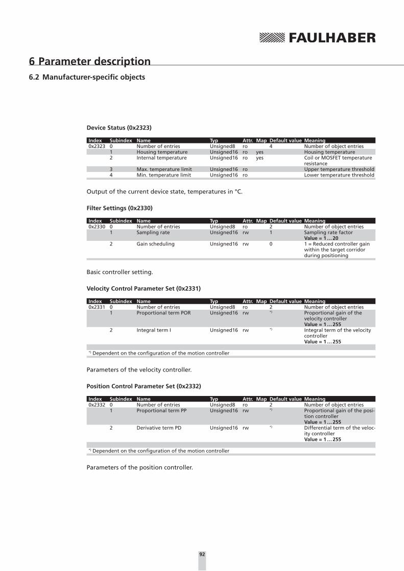
92
6 Parameter description6.2 Manufacturer-specific objects
Device Status (0x2323)
Index Subindex Name Typ Attr. Map Default value Meaning0x2323 0 Number of entries Unsigned8 ro 4 Number of object entries
1 Housing temperature Unsigned16 ro yes Housing temperature2 Internal temperature Unsigned16 ro yes Coil or MOSFET temperature
resistance3 Max. temperature limit Unsigned16 ro Upper temperature threshold4 Min. temperature limit Unsigned16 ro Lower temperature threshold
Output of the current device state, temperatures in °C.
Filter Settings (0x2330)
Index Subindex Name Typ Attr. Map Default value Meaning0x2330 0 Number of entries Unsigned8 ro 2 Number of object entries
1 Sampling rate Unsigned16 rw 1 Sampling rate factorValue = 1 … 20
2 Gain scheduling Unsigned16 rw 0 1 = Reduced controller gain within the target corridor during positioning
Basic controller setting.
Velocity Control Parameter Set (0x2331)
Index Subindex Name Typ Attr. Map Default value Meaning0x2331 0 Number of entries Unsigned8 ro 2 Number of object entries
1 Proportional term POR Unsigned16 rw *) Proportional gain of the velocity controllerValue = 1 … 255
2 Integral term I Unsigned16 rw *) Integral term of the velocity controllerValue = 1 … 255
*) Dependent on the configuration of the motion controller
Parameters of the velocity controller.
Position Control Parameter Set (0x2332)
Index Subindex Name Typ Attr. Map Default value Meaning0x2332 0 Number of entries Unsigned8 ro 2 Number of object entries
1 Proportional term PP Unsigned16 rw *) Proportional gain of the posi-tion controllerValue = 1 … 255
2 Derivative term PD Unsigned16 rw *) Differential term of the veloc-ity controllerValue = 1 … 255
*) Dependent on the configuration of the motion controller
Parameters of the position controller.

93
6 Parameter description6.2 Manufacturer-specific objects
Current Control Parameter Set (0x2333)
Index Subindex Name Typ Attr. Map Default value Meaning0x2333 0 Number of entries Unsigned8 ro 3 Number of object entries
1 Continuous current limit Unsigned16 rw yes *) Continuous current limiting [mA]Value = 1 … 12 000
2 Peak current limit Unsigned16 rw yes *) Peak current limiting [mA]Value = 1 … 12 000
3 Integral term CI Unsigned16 rw yes *) Integral term of the current controllerValue = 1 … 255
*) Dependent on the configuration of the motion controller
Current limiting values and parameters of the current controller.
Actual Current Limit (0x2334)
Index Subindex Name Typ Attr. Map Default value Meaning0x2334 0 Actual current limit Unsigned16 ro yes Currently used current limit-
ing value
General Settings (0x2338)
Index Subindex Name Typ Attr. Map Default value Meaning0x2338 0 Number of entries Unsigned8 ro 3 Number of object entries
1 Pure sinus commutation Unsigned16 rw 1 0 = full control1 = limiting to sine-wave form(not MCDC)
2 Activate position limits in velocity mode
Unsigned16 rw 0 1 = use set positioning range limits, including in velocity mode
3 Activate position limits in position mode
Unsigned16 rw 1 0 = no range limits in posi-tioning mode
General commutation and range limit settings.
By default the range limits are activated in profile position mode. If there are no mechanical limits in the application the limits an also be deactivated in order to carry out unlimited relative positioning. In this case counting continues at 0 if the upper or lower limit is exceeded.
Motor Data (0x2350)
Index Subindex Name Typ Attr. Map Default value Meaning0x2350 0 Number of entries Unsigned8 ro 5 Number of object entries
1 Speed constant KN Unsigned16 rw *) Velocity constant2 Terminal resistance RM Unsigned16 rw *) Connection resistance3 Pole number Unsigned16 rw 2 / 4 *) Pole number for BL motors
(not MCDC)5 Thermal time constant TW1 Unsigned16 rw *) Thermal time constant 1
*) Dependent on the factory configuration of the motion controller
Data sheet values of the connected motor.

94
6 Parameter description6.2 Manufacturer-specific objects
Encoder Data (0x2351)
Index Subindex Name Typ Attr. Map Default value Meaning0x2351 0 Number of entries Unsigned8 ro 3 Number of object entries
1 Sensor type Unsigned8 rw 0 0 = analog Hall (int. encoder)1 = incremental encoder (ext.)10 = incremental + Hall104 = absolute encoder AES-4096(not MCDC)
2 Resolution external encoder Unsigned32 rw 2 048 4 edge resolution of an exter-nally connected incremental encoder
3 Resolution internal encoder Unsigned32 ro 3 000 Resolution of the internal Hall sensor encoder(not MCDC)
Setting of the encoder to be used.
Velocity Actual Value Unfiltered (0x2361)
Index Subindex Name Typ Attr. Map Default value Meaning0x2361 0 Velocity actual value unfil-
teredInteger16 ro Actual speed unfiltered
Baudrate Set (0x2400)
Index Subindex Name Typ Attr. Map Default value Meaning0x2400 0 Baudrate set Unsigned8 ro 0xFF Set baud rate
This object can be used to query which baud rate is set. The index of the set baud rate or 0xFF is returned, if AutoBaud is set.
Baudrate Index Baudrate Index1 000 kbit 0 125 kbit 4800 kbit 1 50 kbit 6500 kbit 2 20 kbit 7250 kbit 3 10 kbit 8
AutoBaud 0xFF
Position Demand Internal Value (0x2562)
Index Subindex Name Typ Attr. Map Default value Meaning0x2562 0 Position demand internal
valueInteger32 ro yes Last target position in inter-
nal units
Target Position Internal Value (0x257A)
Index Subindex Name Typ Attr. Map Default value Meaning0x257A 0 Target position internal value Integer32 rw yes Target position in internal
units

95
6 Parameter description6.2 Manufacturer-specific objects
Position Range Limit Internal Value (0x257B)
Index Subindex Name Typ Attr. Map Default value Meaning0x257B 0 Number of entries Unsigned8 ro 2 Number of object entries
1 Minimum position range limit Integer32 ro yes –1,8 · 106 Internal lower positioning range limit in internal units
2 Maximum position range limit
Integer32 ro yes +1,8 · 106 Internal upper positioning range limit in internal units
Software Position Limit Internal Value (0x257D)
Index Subindex Name Typ Attr. Map Default value Meaning0x257D 0 Number of entries Unsigned8 ro 2 Number of object entries
1 Min. position limit Integer32 rw yes –1,8 · 106 Lower positioning range limit in internal units
2 Max. position limit Integer32 rw yes +1,8 · 106 Upper positioning range limit in internal units

96
6 Parameter description
6.3 Drive profile objects according to CiA 402
Controlword (0x6040)
Index Subindex Name Type Attr. Map Default value Meaning0x6040 0 Controlword Unsigned16 rw yes Drive control
The bits in the controlword are described in Chapter 4.1 “Device control”.
Statusword (0x6041)
Index Subindex Name Type Attr. Map Default value Meaning0x6041 0 Statusword Unsigned16 ro yes Status display
*) PDO mapping possible
The bits in the statusword are described in Chapter 4.1 “Device control”.
Modes of Operation (0x6060)
Index Subindex Name Type Attr. Map Default value Meaning0x6060 0 Modes of operation Integer8 rw yes 1 Operating mode changeover
FAULHABER Motion Control systems support the following operating modes:
1 CiA 402 profile position mode (position control)
3 CiA 402 profile velocity mode (velocity control)
6 CiA 402 homing mode (homing)
Modes of Operation Display (0x6061)
Index Subindex Name Type Attr. Map Default value Meaning0x6061 0 Modes of operation display Integer8 ro yes 1 Display of the set operating
mode
The set operating mode can be queried here, the meaning of the return values corresponds to the values of the object 0x6060.
Position Demand Value (0x6062)
Index Subindex Name Type Attr. Map Default value Meaning0x6062 0 Position demand value Integer32 ro yes Last target position in use-
runits
Position Actual Value (0x6063)
Index Subindex Name Type Attr. Map Default value Meaning0x6063 0 Position actual value Integer32 ro yes Actual position in internal
units

97
6 Parameter description6.3 Drive profile objects according to CiA 402
Position Actual Value (0x6064)
Index Subindex Name Type Attr. Map Default value Meaning0x6064 0 Position actual value Integer32 ro yes Actual position in userunits
Position Window (0x6067)
Index Subindex Name Type Attr. Map Default value Meaning0x6067 0 Position window Unsigned32 rw yes 20 Target position window in
userunits
Position Window Time (0x6068)
Index Subindex Name Type Attr. Map Default value Meaning0x6068 0 Position window time Unsigned16 rw yes 200 Time in target position win-
dow in ms
Velocity Demand Value (0x606B)
Index Subindex Name Type Attr. Map Default value Meaning0x606B 0 Velocity demand value Integer32 ro yes Target velocity in rpm
Velocity Actual Value (0x606C)
Index Subindex Name Type Attr. Map Default value Meaning0x606C 0 Velocity actual value Integer32 ro yes Actual velocity in rpm
Velocity Window (0x606D)
Index Subindex Name Type Attr. Map Default value Meaning0x606D 0 Velocity window Unsigned16 rw yes 20 End velocity window in rpm
Velocity Window Time (0x606E)
Index Subindex Name Type Attr. Map Default value Meaning0x606E 0 Velocity window time Unsigned16 rw yes 200 Time in end velocity window

98
6 Parameter description6.3 Drive profile objects according to CiA 402
Velocity Threshold (0x606F)
Index Subindex Name Type Attr. Map Default value Meaning0x606F 0 Velocity threshold Unsigned16 rw yes 20 Velocity threshold value in
rpm
Velocity Thresold Time (0x6070)
Index Subindex Name Type Attr. Map Default value Meaning0x6070 0 Velocity threshold time Unsigned16 rw yes 200 Time below the velocity
threshold value in ms
Current Actual Value (0x6078)
Index Subindex Name Typ Attr. Map Default value Meaning0x6078 0 Current actual value Integer16 ro yes Current motor current input
in mA
Target Position (0x607A)
Index Subindex Name Type Attr. Map Default value Meaning0x607A 0 Target position Integer32 rw yes Target position in userunits
Position Range Limit (0x607B)
Index Subindex Name Typ Attr. Map Default value Meaning0x607B 0 Number of entries Unsigned8 ro 2 Number of object entries
1 Min. position range limit Integer32 ro –1,8 · 109 Internal lower positioning range limit in userunits
2 Max. position range limit Integer32 ro +1,8 · 109 Internal upper positioning range limit in userunits
Homing Offset (0x607C)
Index Subindex Name Type Attr. Map Default value Meaning0x607C 0 Homing offset Integer32 rw yes 0 Zero point displacement from
the reference position in userunits

99
6 Parameter description6.3 Drive profile objects according to CiA 402
Software Position Limit (0x607D)
Index Subindex Name Type Attr. Map Default value Meaning0x607D 0 Number of entries Unsigned8 ro 2 Number of object entries
1 Min. position limit Integer32 rw yes –1.8 · 109 Lower positioning range limit in userunits
2 Max. position limit Integer32 rw yes +1.8 · 109 Upper positioning range limit in userunits
Range limits settable in user units.
Polarity (0x607E)
Index Subindex Name Type Attr. Map Default value Meaning0x607E 0 Polarity Unsigned8 rw yes 0 Direction of rotation
This object can be used to globally change the direction of rotation, i.e. the default and actual values for position and speed are multiplied by –1:
Bit 7 = 1 negative direction of rotation in positioning mode
Bit 6 = 1 negative direction of rotation in velocity mode
Max Profile Velocity (0x607F)
Index Subindex Name Type Attr. Map Default value Meaning0x607F 0 Max profile velocity Unsigned32 rw yes *) Maximum velocity in rpm
Value = 0 … 30 000
*) Dependent on the factory configuration of the motion controller
Profile Velocity (0x6081)
Index Subindex Name Type Attr. Map Default value Meaning0x6081 0 Profile velocity Unsigned32 rw yes *) Maximum velocity in rpm
Value = 0 … 30 000
*) Dependent on the factory configuration of the motion controller
Profile Acceleration (0x6083)
Index Subindex Name Type Attr. Map Default value Meaning0x6083 0 Profile acceleration Unsigned32 rw yes 30 000 Maximum acceleration in 1/s²
Value = 0 … 32 000

100
6 Parameter description6.3 Drive profile objects according to CiA 402
Profile Deceleration (0x6084)
Index Subindex Name Type Attr. Map Default value Meaning0x6084 0 Profile deceleration Unsigned32 rw yes 30 000 Maximum delay in 1/s²
Value = 0 … 32 000
Quick Stop Decelaration (0x6085)
Index Subindex Name Type Attr. Map Default value Meaning0x6085 0 Quick stop deceleration Unsigned32 rw yes 30 000 Quick stop braking ramp
value in 1/s²Value = 0 … 32 000
Position Encoder Resolution (0x608F)
Index Subindex Name Type Attr. Map Default value Meaning0x608F 0 Number of entries Unsigned8 ro 2 Number of entries
1 Encoder increments Unsigned32 ro 3 000 / 2 048 *) Resolution of the external en-coder for 4 edge evaluation
2 Motor revolutions Unsigned32 ro 1 Number of motor revolu-tions with the pulse number named in subindex 1
*) BL-Controllers / MCDC
The value of the encoder resolution is copied from the settings in the encoder data object (0x2351) and cannot be changed here.
Gear Ratio (0x6091)
Index Subindex Name Typ Attr. Map Default value Meaning0x6091 0 Number of entries Unsigned8 ro 2 Number of entries
1 Motor revolutions Unsigned32 rw 1 Number of motor revolu-tions
2 Shaft revolutions Unsigned32 rw 1 Number of revolutions of the output shaft
Feed Constant (0x6092)
Index Subindex Name Typ Attr. Map Default value Meaning0x6092 0 Number of entries Unsigned8 ro 2 Number of entries
1 Feed Unsigned32 rw 3 000 / 2 048 *) Feed in userunits2 Shaft revolutions Unsigned32 rw 1 Number of revolutions of
the output shaft
*) BL-Controllers / MCDC
The gear ratio ad feed constant factors can be used to specify a gear ratio and a feed value for con-verting into user units (see Chapter 4.2 “Factor group”).
On delivery the user units are set to the default encoder resolution (3 000 or 2 048 increments per revolution).

101
6 Parameter description6.3 Drive profile objects according to CiA 402
Position Factor (0x6093)
Index Subindex Name Type Attr. Map Default value Meaning0x6093 0 Number of entries Unsigned8 ro 2 Number of object entries
1 Position factor numerator Unsigned32 ro 1 Numerator of the position factor
2 Position factor divisor Unsigned32 ro 1 Denominator (divisor) of the position factor
internal position =position in userunits × position factor numerator
position factor denominator
The position factor is calculated from the position encoder resolution (0x608F), gear ratio (0x6091) and feed constant (0x6092) and cannot be changed here (see Chapter 4.2 “Factor group”)
Homing Method (0x6098)
Index Subindex Name Type Attr. Map Default value Meaning0x6098 0 Homing method Integer8 rw yes 20 Homing method according to
CiA 402
Homing Speed (0x6099)
Index Subindex Name Type Attr. Map Default value Meaning0x6099 0 Number of entries Unsigned8 ro 2 Number of object entries
1 Switch seek velocity Unsigned32 rw yes 400 Speed during switch search in rpmValue = 0 … 30 000
2 Homing velocity Unsigned32 rw yes 100 Speed during search for zero in rpmValue = 0 … 30 000
Homing Acceleration (0x609A)
Index Subindex Name Type Attr. Map Default value Meaning0x609A 0 Homing acceleration Unsigned32 rw yes 50 Acceleration during homing
in 1/s²Value = 0 … 30 000
Control Effort (0x60FA)
Index Subindex Name Type Attr. Map Default value Meaning0x60FA 0 Control effort Unsigned32 ro yes Controller output

102
6 Parameter description6.3 Drive profile objects according to CiA 402
Digital Inputs (0x60FD)
Index Subindex Name Typ Attr. Map Default value Meaning0x60FD 0 Digital inputs Unsigned32 ro yes State of digital inputs
By way of the following bits, the digital inputs object indicates which switch is switched on or off:
� Bit 0: Negative limit switch
� Bit 1: Positive limit switch
� Bit 2: Homing switch
Target Velocity (0x60FF)
Index Subindex Name Type Attr. Map Default value Meaning0x60FF 0 Target velocity Integer32 rw yes Target velocity in rpm
Value = 0 … 30 000
Supported Drive Modes (0x6502)
Index Subindex Name Typ Attr. Map Default value Meaning0x6502 0 Supported drive modes Unsigned32 ro yes 0×25 Supported operating modes
The Supported Drive Modes object indicates the operating modes supported by the FAULHABER Mo-tion Control System:
� Bit 0: Profile position mode (pp)
� Bit 2: Profile velocity mode (pv)
� Bit 5: Homing mode (hm)

103
Notes

WE CREATE MOTIONMA05037 English, 2nd edition, 12.2013© DR. FRITZ FAULHABER GMBH & CO. KGSubject to change without notice
DR. FRITZ FAULHABERGMBH & CO. KGAntriebssysteme
Daimlerstraße 23 / 2571101 Schönaich · GermanyTel. +49(0)7031/638-0Fax +49(0)7031/[email protected]