commonwealth of pennsylvania - dot.state.pa.us 8/pub 8.pdf · concrete collar for pipe extension...
TRANSCRIPT


COMMONWEALTH OF PENNSYLVANIA
DEPARTMENT OF TRANSPORTATION
CONSTRUCTION MANUAL
2008 Edition
Pub 8 (4-08)

This Page Left Intentionally Blank

Table of Contents
Introduction
Section 000—Organization of an Engineering District (Construction) 1. General Policies and Provisions ............................................................................................000-1 2. District Executive ..................................................................................................................000-2 3. Assistant District Executive—Design ...................................................................................000-3 4. Assistant District Executive—Maintenance ..........................................................................000-4 5. Assistant District Executive—Construction ..........................................................................000-5 6. Assistant Construction Engineer............................................................................................000-6 7. Structure Control Engineer ....................................................................................................000-7 8. Materials Engineer.................................................................................................................000-8 9. Construction Services Engineer.............................................................................................000-9 10. Proposal and Work Order Review.......................................................................................000-10 11. Inspector-in-Charge .............................................................................................................000-11 12. Inspectors.............................................................................................................................000-12 13. Labor Compliance/EEO Coordinator ..................................................................................000-13 14. Finals Unit ...........................................................................................................................000-14 15. Geotechnical Engineer.........................................................................................................000-15
Section 100—General Policies and Provisions 1. Relations with the Contractor ................................................................................................100-1 2. Relations with Public Utility Companies ..............................................................................100-3 3. Relations with Railroads........................................................................................................100-4 4. Relations with the Federal Highway Administration ............................................................100-5 5. Legal Relations and Responsibility to the Public ..................................................................100-6 6. Provision for Right-of-Way...................................................................................................100-7 7. Incident Management Plan ....................................................................................................100-8 8. Constructability Review ........................................................................................................100-9 9. Pre-Bid Conference .............................................................................................................100-10 10. Pre-Construction Conference...............................................................................................100-11 11. Project Records....................................................................................................................100-13 12. Performance and Progress ...................................................................................................100-15 13. Measuring Quantities and Payments ...................................................................................100-16
PennDOT Publication 8 TOC-i

Table of Contents 14. Work Authorizations ...........................................................................................................100-17 15. Work Orders ........................................................................................................................100-18 16. Preservation and Protection of Monuments and Markers....................................................100-19 17. Notice to Property Owners ..................................................................................................100-20 18. Survey and Stake-Out ..........................................................................................................100-21
Section 200—Earthwork 1. Clearing and Grubbing ..........................................................................................................200-1 2. Demolition, Disposal, and Storage of Existing Structures and Buildings .............................200-4 3. Excavation .............................................................................................................................200-8 4. Embankment Placement ......................................................................................................200-17 5. Waste Material.....................................................................................................................200-25 6. Borrow Excavation ..............................................................................................................200-27 7. Compaction..........................................................................................................................200-30 8. Subgrade ..............................................................................................................................200-33 9. Geotextiles ...........................................................................................................................200-38 10. Flowable Fill........................................................................................................................200-41
Section 300—Base Courses 1. Importance of Base Courses ..................................................................................................300-1 2. Types of Bases.......................................................................................................................300-3
A. Cement Treated Permeable Base Course .....................................................................300-3 B. Bituminous Concrete Base Courses.............................................................................300-6 C. Superpave Asphalt HMA Base Course......................................................................300-10 D. Aggregate Bituminous Base Course ..........................................................................300-14 E. Aggregate-Cement Base Course ................................................................................300-17 F. Cold Recycled Bituminous Base Course, Cold-in-Place ...........................................300-21 G. Cold Recycled Bituminous Base Course, Central Plant ............................................300-24 H. Asphalt Treated Permeable Base Course ...................................................................300-27
Section 350—Subbase 1. Subbase..................................................................................................................................350-1
Section 400—Flexible Pavement 1. Bituminous Paving with Conventional & Superpave Mixture Design, Construction of
Plant-Mixed Hot Mix Asphalt (HMA) Courses, Standard and Restricted Performance Specification (RPS) ...............................................................................................................400-1
2. Evaluation of Bituminous Pavement Ride Quality and Payment of Incentive ....................400-10 3. Bituminous Tack Coat .........................................................................................................400-12 4. Bituminous Prime Coat .......................................................................................................400-14 5. Heavy-Duty Membranes......................................................................................................400-16 6. Asphalt Joint and Crack Sealing..........................................................................................400-18
PennDOT Publication 8 TOC-ii

Table of Contents 7. Bituminous Seal Coat & Bituminous Seal Coat Using Precoated Aggregate;
Bituminous Surface Treatment & Bituminous Surface Treatment Using Pre-Coated Aggregate.............................................................................................................................400-20
8. Slurry Seal ...........................................................................................................................400-23 9. Removal of Existing Surface Course...................................................................................400-25 10. Milling of Bituminous Pavement Surface, Profile Milling, Variable Depth .......................400-27 11. Preparation of Bases ............................................................................................................400-29 12. Operation of Paver...............................................................................................................400-31
A. Checking Thickness of Mat .......................................................................................400-32 13. Hand Spreading and Finishing.............................................................................................400-34 14. Compacting Binder and Wearing Courses ..........................................................................400-36 15. Constructing Longitudinal Joints.........................................................................................400-38 16. Constructing Transverse Joints............................................................................................400-40 17. Testing HMA.......................................................................................................................400-42 18. Protection of Surface Courses .............................................................................................400-44 19. Shoulder Construction .........................................................................................................400-45
Section 500—Rigid Pavement 1. Reinforced or Plain Cement Concrete Pavements, Reinforced or Plain Cement
Concrete Pavement (RPS), and Protective Coating for Cement Concrete Pavement............500-1 2. Pavement Relief Joint ............................................................................................................500-7 3. Bridge Approach Slabs ..........................................................................................................500-9 4. Evaluation of Concrete Pavement Ride Quality and Payment of Incentive ........................500-12 5. Longitudinal Grooving of Existing Concrete Pavement, Transverse Grooving of
Concrete pavements for Retexturing, and Diamond Grinding of Concrete Pavement........500-15 6. Pressure Relief Joint, Longitudinal Joint Cleaning and Sealing, Joint Rehabilitation,
Transverse Joint Cleaning and Sealing, and Crack Cleaning and Sealing ..........................500-18 7. Sawing and Sealing of Bituminous Overlays ......................................................................500-22 8. Concrete Pavement Patching and Continuously Reinforced Concrete Pavement
Patching ...............................................................................................................................500-24 9. Thin Bonded Portland Cement Concrete Overlay ...............................................................500-29 10. Concrete Pavement Spall Repair .........................................................................................500-32 11. Rubblizing of Concrete Pavements .....................................................................................500-35
Section 600—Incidental Construction 1. Pipe Culverts..........................................................................................................................600-1
A. Endwalls, Inlets, Manholes, and Spring Boxes............................................................600-5 2. Grade Adjustment of Existing Miscellaneous Structures ......................................................600-8 3. Rebuilt Miscellaneous Structures ........................................................................................600-11 4. Pipe Underdrain and Pavement Base Drain.........................................................................600-14 5. Subgrade Drains ..................................................................................................................600-16 6. Stone Backfill for Miscellaneous Drainage .........................................................................600-18 7. Subsurface Drain Outlet ......................................................................................................600-20 8. End Sections and Slope Pipe Fittings ..................................................................................600-22 9. Slotted Drains ......................................................................................................................600-24
PennDOT Publication 8 TOC-iii
Table of Contents 10. Concrete Collar for Pipe Extension .....................................................................................600-26 11. Permanent Impact Attenuating Devices ..............................................................................600-29 12. Guide Rails ..........................................................................................................................600-31 13. Metal Median Barriers.........................................................................................................600-34 14. Concrete Glare Screen .........................................................................................................600-37 15. Concrete Median Barrier .....................................................................................................600-40 16. Right-of-Way Fence ............................................................................................................600-43 17. Gabions................................................................................................................................600-46 18. Curbs and Gutters ................................................................................................................600-48
A. Plain Cement Concrete Curb .....................................................................................600-48 B. Plain Concrete Mountable Curb.................................................................................600-51 C. Bituminous Concrete Curb ........................................................................................600-54 D. Plain Cement Concrete Gutter and Curb Gutter ........................................................600-56
19. Shoulder Rumble Strips.......................................................................................................600-59 20. Brick Masonry .....................................................................................................................600-61 21. Modular Architectural Block System ..................................................................................600-64 22. Cement Concrete Paving for Stream Beds ..........................................................................600-66 23. Pre-Cast Cement Concrete Block Slope Wall, Cast-in-Place Cement Concrete Slope
Wall .....................................................................................................................................600-69 24. Stone Slope Walls................................................................................................................600-72 25. Random Stone Slope Wall...................................................................................................600-75 26. Cement Concrete Sidewalks ................................................................................................600-78 27. Selected Material Surfacing.................................................................................................600-81 28. Permanent Barricades ..........................................................................................................600-83 29. Slab Stabilization.................................................................................................................600-85 30. Waterproofing......................................................................................................................600-88 31. Slabjacking ..........................................................................................................................600-90 32. Construction Surveying .......................................................................................................600-92 33. Built-Up Curb Ramps..........................................................................................................600-94 34. Temporary Impact Attenuating Devices and Reset Temporary Impact Attenuating
Devices ................................................................................................................................600-96
Section 800—Roadside Development 1. Stockpiling Topsoil or Topsoil Mixture, Topsoil Furnished and Placed, Placing
Stockpiled Topsoil or Topsoil Mixture..................................................................................800-1 2. Seeding and Soil Supplements...............................................................................................800-6 3. Water Course and Slope Erosion Protection..........................................................................800-9 4. Plants, Planting, and Transplanting .....................................................................................800-11 5. Sodding................................................................................................................................800-13 6. Selective Tree Removal and Trimming...............................................................................800-16 7. Temporary Protective Fence for Existing Plant Material ....................................................800-18 8. Erosion and Sedimentation Control Measures/Environmental Compliance .......................800-20
A. Unforeseen Water Pollution Control .........................................................................800-21 B. Rock Lining and Rock Basin .....................................................................................800-23 C. Rock Energy Dissipator and Paved Energy Dissipator..............................................800-26 D. Temporary Slope Pipe Drain .....................................................................................800-30
PennDOT Publication 8 TOC-iv
Table of Contents
E. Dewatering Basin.......................................................................................................800-32 F. Rock Barrier...............................................................................................................800-34 G. Concrete Block Revetment Systems..........................................................................800-36 H. Geocell Confinement System ....................................................................................800-39 I. Sedimentation Pond, Sediment Trap, and Sedimentation Structure Cleaning...........800-42 J. Standboxes .................................................................................................................800-46 K. Diversion Ditch..........................................................................................................800-48 L. Silt Barrier Fence .......................................................................................................800-50 M. Sediment Filter Bags..................................................................................................800-52 N. Wetland Mitigation ....................................................................................................800-54 O. Working Around Existing Wetlands..........................................................................800-56 P. Working in Stream Channels .....................................................................................800-58
Section 900—Traffic Accommodation and Control 1. Maintenance and Protection of Traffic During Construction and During Temporary
Suspension of Work (including Placing and Resetting Temporary Concrete Barriers) ........900-1 2. Temporary Bridge and Approaches.......................................................................................900-3 3. Highway Lighting & Sign Lighting.......................................................................................900-5 4. Post Mounted Signs ...............................................................................................................900-9
A. Post Mounted Signs: Type A and Type B ...................................................................900-9 B. Post Mounted Signs: Type C and Type E..................................................................900-13 C. Post Mounted Signs: Type D and Type F..................................................................900-16
5. Structure Mounted Signs .....................................................................................................900-18 6. Delineation Devices and Distance Markers.........................................................................900-20 7. Steel Sign Structures............................................................................................................900-22 8. Traffic Signals (General) .....................................................................................................900-25 9. Traffic Signal Supports........................................................................................................900-28 10. Controller Assembly and Traffic Signal Systems................................................................900-30 11. Electrical Distribution and Traffic Signal Communication.................................................900-33 12. Signal Heads and Detectors .................................................................................................900-36 13. Hot Thermoplastic Pavement Markings, Preformed Thermoplastic Pavement
Markings, and Cold Plastic Pavement Markings or Legends ..............................................900-38 14. Waterborne Pavement Markings and Epoxy Pavement Markings ......................................900-42 15. Pavement Marking Removal ...............................................................................................900-45 16. Snowplowable Raised Pavement Markers...........................................................................900-47
Section 1000—Structures 1. Cement Concrete Construction............................................................................................1000-1
A. Concrete Formwork ...................................................................................................1000-1 B. Reinforcement Bars (Rebar) ......................................................................................1000-4 C. Concrete Placement ...................................................................................................1000-7 D. Concrete Curing.......................................................................................................1000-10 E. Protective Coating of Reinforced Concrete Surfaces ..............................................1000-13
PennDOT Publication 8 TOC-v
Table of Contents 2. Cement Concrete Structures ..............................................................................................1000-16
A. Footings ...................................................................................................................1000-16 B. Abutments................................................................................................................1000-20 C. Integral Abutments ..................................................................................................1000-24 D. Piers .........................................................................................................................1000-27 E. Bridge Decks............................................................................................................1000-31 F. Bridge Parapets ........................................................................................................1000-36 G. Placement of Concrete Beams .................................................................................1000-40 H. Reinforced Concrete Retaining Walls .....................................................................1000-44 I. Reinforced Concrete Box Culverts ..........................................................................1000-48
3. Piles ...................................................................................................................................1000-52 4. Drilled Caissons.................................................................................................................1000-56 5. Mechanically Stabilized Earth (MSE) Walls.....................................................................1000-59 6. Permanent Soldier Pile Walls ............................................................................................1000-64 7. Sound Barriers ...................................................................................................................1000-67 8. Temporary Excavation Support System ............................................................................1000-71 9. End Dams ..........................................................................................................................1000-74
A. Tooth Expansion Dam with Drain Trough ..............................................................1000-74 B. Armored Preformed Neoprene Compression Dam..................................................1000-76 C. Neoprene Strip Seal Dam.........................................................................................1000-78
10. Preformed Neoprene Compression Joint Seals for Bridges...............................................1000-80 11. Structural Backfill..............................................................................................................1000-82 12. Structural Drainage............................................................................................................1000-84
A. Downspouting..........................................................................................................1000-84 B. Scuppers...................................................................................................................1000-86
13. Removal of Existing Bridges or Culverts ..........................................................................1000-87 14. Concrete Repairs................................................................................................................1000-89
A. Concrete Bridge Deck Repair ..................................................................................1000-89 B. Scarification .............................................................................................................1000-91 C. Epoxy Injection Crack Repairs ................................................................................1000-92 D. Pressure Mortar Pointing and Grouting (Guniting) .................................................1000-94
15. Latex Modified Mortar or Concrete Wearing Surface.......................................................1000-96 16. Timber Structures ..............................................................................................................1000-99 17. Continuous Span Construction ........................................................................................1000-102 18. Structural Steel ................................................................................................................1000-104 19. Structural Steel Painting ..................................................................................................1000-108
A. Painting Existing Structural Steel ..........................................................................1000-108 B. Spot/Zone Maintenance of Structural Steel ...........................................................1000-112
20. Anchor Bolts....................................................................................................................1000-115 21. Beam Seats/Bearings .......................................................................................................1000-117 22. Railings/Hand Railings/Pedestrian Railings....................................................................1000-120
Glossary
PennDOT Publication 8 TOC-vi

Publication “8” Introduction
This version of the Construction Manual (Publication 8) updates the previous version dated 1975. The Construction Manual is to be used as a guide and a reference for the Inspector in the field. It contains valuable information not found in other manuals or publications.
This manual should assist the Inspector in performing his duties by providing him with what is considered good construction practices on the different phases of the project. The contractor may have a better method than those outlined herein but he must obtain the same end result. The updated Publication 8 will reference the Publication 408, Standard Drawings and other contract documents, but it is NOT a contract governing document. The information contained in Publication 8 has been developed based on Publication 408/2007. Since changes do occur, user's of this manual are to determine the Publication 408 version applicable to their project and whether the contract documents include any special provisions that would modify the information that is presented in this manual.
The updated manual follows the sections of Publication 408 except sections 700 and 1100 are not included. Information relative to these sections is included in other sections. The chapters within the sections are organized using the following format:
• Chapter Title • Introduction • References • Material & Equipment • Construction Methods • Measuring & Payment Methods • Documentation • Key Elements checklist
While all sections are important the “Key Elements checklist” could be considered the heart of the manual and identifies the key elements that must be considered before, during and after a given construction operation. It also includes a checklist of what to look for while inspecting this operation.
PennDOT Publication 8 Introduction-1

Publication “8” Introduction
This Page Left Intentionally Blank
PennDOT Publication 8 Introduction-2
Section 000—Organization of an Engineering District (Construction)
PennDOT Publication 8 000-i
Table of Contents 1. General Policies and Provisions ............................................................................................000-1 2. District Executive ..................................................................................................................000-2 3. Assistant District Executive—Design ...................................................................................000-3 4. Assistant District Executive—Maintenance ..........................................................................000-4 5. Assistant District Executive—Construction ..........................................................................000-5 6. Assistant Construction Engineer............................................................................................000-6 7. Structure Control Engineer ....................................................................................................000-7 8. Materials Engineer.................................................................................................................000-8 9. Construction Services Engineer.............................................................................................000-9 10. Proposal and Work Order Review.......................................................................................000-10 11. Inspector-in-Charge .............................................................................................................000-11 12. Inspectors.............................................................................................................................000-12 13. Labor Compliance/EEO Coordinator ..................................................................................000-13 14. Finals Unit ...........................................................................................................................000-14 15. Geotechnical Engineer.........................................................................................................000-15

Section 000—Organization of an Engineering District (Construction)
PennDOT Publication 8 000-ii
This Page Left Intentionally Blank

Section 000—Organization of an Engineering District (Construction)
PennDOT Publication 8 000-1
1. General Policies and Provisions This chapter addresses general policies and provisions regarding the organization of an engineering district.
The Pennsylvania Department of Transportation divides the Commonwealth into eleven Engineering Districts, each headed by a district executive. The district executive is assisted in the operation of the Engineering District by the following individuals and their staff: assistant district executive—design, assistant district executive—maintenance, assistant district executive—construction, community relations coordinator, district fiscal control officer, and district human resources officer.
A typical District is organized along the following lines, however it should be noted that several districts have organizational variances under the ADEs for instance one has the contract management unit in construction other units are under different ADEs depending on the District. One District has a fourth ADE.
Section 000—Organization of an Engineering District (Construction)
PennDOT Publication 8 000-2
2. District Executive The district executive is in charge of all work performed in the District. This includes all functions, including design, construction and maintenance of highways and bridges, coordination with municipalities, and issuance of permits for access to state highways and design of traffic signals. The district executive’s responsibility also includes programming, budgeting, personnel assignments, and performance review.
It is the district executive’s responsibility to ensure that all contracts for work within the District are fulfilled as written, including compliance with the specifications, drawings, special provisions, and standard drawings.
Section 000—Organization of an Engineering District (Construction)
PennDOT Publication 8 000-3
3. Assistant District Executive—Design The assistant district executive (ADE)—design is responsible for coordinating all activities in the District concerning the design of highways and bridges. The activities include those related to geotechnical issues, structures, planning organizations, and plan and contract development. Surveying, utility relocations, and right-of-way also come under the jurisdiction of the ADE—design.
Section 000—Organization of an Engineering District (Construction)
PennDOT Publication 8 000-4
4. Assistant District Executive—Maintenance The assistant district executive (ADE)–maintenance is responsible for coordinating all activities related to accidents, traffic, roadside maintenance, municipal services, access and hauling permits, and maintenance of roadways and bridges (including snow removal). County maintenance managers and their staff report to the ADE—maintenance.
Section 000—Organization of an Engineering District (Construction)
PennDOT Publication 8 000-5
5. Assistant District Executive—Construction The assistant district executive (ADE)–construction is responsible for coordinating all activities related to contract construction work. To accomplish this, the ADE has a staff that includes a support services engineer, assistant construction engineers, materials engineers and individuals responsible for safety, equal employment opportunity (EEO), labor compliance, work orders, finals, and audits. The safety, EEO, and labor compliance functions are often assigned to one individual.
Section 000—Organization of an Engineering District (Construction)
PennDOT Publication 8 000-6
6. Assistant Construction Engineer The assistant district construction engineer (ACE) is responsible for overseeing and monitoring several construction projects within the District. This ACE is the immediate supervisor of the inspector-in-charge and functions as a coordinator between the inspector-in-charge and district units to assist in resolving issues and problems.
The ACE chairs the pre-construction meeting, conducts final inspections, and monitors the progress of the project (including estimates). The ACE also assists the inspector-in-charge in resolving compliance issues with the contractor and in obtaining assistance in resolving project issues.

Section 000—Organization of an Engineering District (Construction)
PennDOT Publication 8 000-7
7. Structure Control Engineer The structure control engineer is responsible for providing specialized engineering guidance and direction relating to structures. The structure control engineer should inspect all bridge foundations during construction, review deck placement procedures, review falsework submissions, and be consulted whenever non-routine construction problems are encountered. In some Districts, an ACE also serves as the structure control engineer.
Section 000—Organization of an Engineering District (Construction)
PennDOT Publication 8 000-8
8. Materials Engineer The materials engineer is responsible for approval and monitoring of aggregate sources, bituminous concrete plants, and Portland cement concrete plants. This responsibility includes plants established on the project sites.
The materials engineer and staff members review quality control plans for the various facilities and project-specific plans for paving operations. The staff provides inspection and monitoring at bituminous and concrete plants, as well as periodic sampling, inspection, and testing of aggregate sources. They are also available for assistance with project-related issues.
Section 000—Organization of an Engineering District (Construction)
PennDOT Publication 8 000-9
9. Construction Services Engineer The construction services engineer is responsible for a number of functions. These include: monitoring contractors’ compliance with labor requirements (such as wage rates, and trainees), monitoring contractors’ safety plans, monitoring contractors’ compliance with EEO requirements; and processing work orders and other information related to construction contracts. Duties assigned to the construction services engineer may vary by District.
Section 000—Organization of an Engineering District (Construction)
PennDOT Publication 8 000-10
10. Proposal and Work Order Review One individual in the District Construction Unit is responsible for work order and proposal review. He or she reviews proposals for construction projects prior to bid, with an emphasis on items such as clarity, completeness, constructability, and bidability, then provides comments to the design project manager to ensure that the highest-quality plans are provided for bid to contractors.
During the construction of projects, conditions sometimes require adjustments to quantities or additional items not anticipated in the design process. Also, the Department sometimes finds it necessary to have the contractor perform the work using the force account procedure. In such instances, work orders must be generated by the project inspection staff and submitted to the District for review and approval.
Section 000—Organization of an Engineering District (Construction)
PennDOT Publication 8 000-11
11. Inspector-in-Charge The inspector-in-charge of a project is responsible for all inspection work on a project, and for providing direction and guidance to the inspectors. He or she monitors the various contractor activities, visits field operations, reviews reports and other records, and monitors sampling and testing of materials.
The inspector-in-charge is responsible for explaining to a property owner how the project will affect the owner’s property. He or she should not discuss damages or indicate what settlement the property owner will receive; the right-of-way administrator provides this information. The inspector-in-charge, however, is responsible for notifying the contractor not to trespass or do any work on private property unless the contractor has written permission from the property owner.
If the inspector-in-charge finds that a structure or slope will extend beyond the right-of-way limit, he or she should report this to the assistant district construction engineer before construction is started. He or she should also report any condition that will require more work or material than indicated in the contract.
The inspector-in-charge also ensures that the contractor’s maintenance and protection of traffic efforts are in compliance with the approved plans, and directs appropriate changes when required. If a detour is utilized, the inspector-in-charge is responsible for monitoring the detour conditions.
Section 000—Organization of an Engineering District (Construction)
PennDOT Publication 8 000-12
12. Inspectors
Inspectors are assigned to a construction project to assist the inspector-in-charge in monitoring the contractors operations. Inspectors have various levels of experience and carry titles and responsibilities accordingly.
Inspectors monitor the contractor’s work for compliance with the contract, observe and document quality control testing, record information, and document quantities for completed work.

Section 000—Organization of an Engineering District (Construction)
PennDOT Publication 8 000-13
13. Labor Compliance/EEO Coordinator Department construction contracts contain two requirements relative to the contractor’s workforce:
• Wage rates for various classifications of employees, including laborers, operators, carpenters, and flaggers.
• A commitment by the contractor to have a certain portion of the work performed by Disadvantaged Business Enterprises (DBE), Women’s Business Enterprises (WBE), or Minority Business Enterprises (MBE).
The construction inspection staff is responsible for monitoring wage rates through interviews and payroll reviews. Contractor payrolls are also submitted to the district labor compliance officer for review and approval. If the project staff identify a problem, the district labor compliance officer assists in its resolution.
At the time the contractor submits a bid, he or she commits to subcontracting a percentage of the work to DBE, WBE, or MBE firms. During the course of construction, this percentage is closely monitored via payrolls and estimates. The district EEO coordinator will periodically visit the project site for spot reviews or to assist the inspection staff in resolving issues.
Section 000—Organization of an Engineering District (Construction)
PennDOT Publication 8 000-14
14. Finals Unit The finals unit conducts a final audit of the project records after the completion of construction. Duties for this unit vary by District. Staff is usually available to assist in setting up project records and may perform periodic audits to ensure conformance.
Section 000—Organization of an Engineering District (Construction)
PennDOT Publication 8 000-15
15. Geotechnical Engineer The geotechnical engineer is responsible for all work related to geology and associated engineering. He or she is responsible for oversight of geotechnical research and design for foundations, slopes, and other issues in the design phase. The geotechnical engineer also assists with construction related issues, such as foundations, sinkholes, slides, and unstable material.

Section 000—Organization of an Engineering District (Construction)
PennDOT Publication 8 000-16
This Page Left Intentionally Blank

Section 100—General Policies and Provisions
Table of Contents 1. Relations with the Contractor ................................................................................................100-1 2. Relations with Public Utility Companies ..............................................................................100-3 3. Relations with Railroads........................................................................................................100-4 4. Relations with the Federal Highway Administration ............................................................100-5 5. Legal Relations and Responsibility to the Public ..................................................................100-6 6. Provision for Right-of-Way...................................................................................................100-7 7. Incident Management Plan ....................................................................................................100-8 8. Constructability Review ........................................................................................................100-9 9. Pre-Bid Conference .............................................................................................................100-10 10. Pre-Construction Conference...............................................................................................100-11 11. Project Records....................................................................................................................100-13 12. Performance and Progress ...................................................................................................100-15 13. Measuring Quantities and Payments ...................................................................................100-16 14. Work Authorizations ...........................................................................................................100-17 15. Work Orders ........................................................................................................................100-18 16. Preservation and Protection of Monuments and Markers....................................................100-19 17. Notice to Property Owners ..................................................................................................100-20 18. Survey and Stake-Out ..........................................................................................................100-21
PennDOT Publication 8 100-i
Section 100—General Policies and Provisions
PennDOT Publication 8 100-ii
This Page Left Intentionally Blank
Section 100—General Policies and Provisions
1. Relations with the Contractor This chapter addresses relations with the contractor—the individual, firm, or corporation that has agreed to perform the construction work in accordance with the conditions and costs contained in the contract.
Reference Publication 408, Section 105 (Control of Work)
Discussion Department personnel and inspectors should cooperate with the contractor and the contractor’s representatives in accomplishing the work. It is, however, the responsibility of the Department and its inspectors to strictly enforce all contract requirements, specifications, special provisions, and drawings.
The contractor is responsible for the entire project from the date the notice to proceed is issued until final acceptance as noted in the acceptance certificate. The presence of Department personnel and inspectors does not relieve the contractor of his or her responsibility to perform all work in accordance with the contract documents.
The contractor must assign a superintendent or representative to the project that is experienced and familiar with the work and with PennDOT’s policies and procedures. The inspector cannot act as the contractor’s superintendent or foreman, nor operate or adjust any of the construction equipment. However, if the contractor’s representative or superintendent fails to control the work effectively, it is the duty of the Inspector-in-Charge to notify his supervisor.
If poor workmanship is found on an operation or any item of work is found unsatisfactory, resulting in construction that does not meet Department specifications, the inspector should immediately notify the contractor. The inspector, however, should not give orders to laborers or other workmen on the project.
If the contractor fails to take corrective action, the Inspector-in-Charge should immediately notify his supervisor. All facts, including warning dates, detailed records, and any agreements made, should be recorded in a PSA.
PennDOT Publication 8 100-1
Section 100—General Policies and Provisions The inspector should know in advance what materials and equipment the contractor will need and may offer the contractor any advice that will help the contractor to perform the work according to specifications. The inspector has the authority to reject materials or hold up the work until a decision can be obtained from the Inspector-in-Charge or other authority. Inspectors should use their own judgement when making decisions on small points not covered in written instruction, but important points should be brought to the attention of the Inspector-in-Charge or a higher authority. The contractor should immediately be notified if these situations occur.
When it is expected that the contractor may make claims, the Inspector-in-Charge of the project should notify the Department promptly. Detailed records should be kept of all labor, materials, and equipment used on this part of the work.
The Inspector-in-Charge is responsible for scheduling the inspectors to ensure that they are on the job prior to the contractor commencing any operation and that they remain on the job until all operations have been completed. If the contractor desires to complete certain operations beyond normal working hours, the assigned inspector should remain on the job and notify the Inspector-in-Charge.
The contractor and Inspector-in-Charge should coordinate a list of emergency contacts and telephone numbers. The Inspector-in-Charge should maintain a list of all inspectors and their telephone numbers to reach them in the event of an emergency.
PennDOT Publication 8 100-2

Section 100—General Policies and Provisions 2. Relations with Public Utility Companies This chapter addresses relations with public utilities that own utilities or structures in the right-of-way or within the project boundaries.
Reference Publication 408, Section 105 (Control of Work)
Discussion When the Department has been notified that a project is to start, the district staff makes arrangements for clearing right-of-way obstructions to avoid delays. Arrangements must also be made for the removal, resetting, construction, or reconstruction of public utilities or utility structures that may otherwise delay the contractor’s operations. However, these Department arrangements do not relieve the contractor of his or her responsibility for public and private structures on the project.
Upon execution of the contract, the contractor must notify the responsible officers of the utility about their utilities or structures in the right-of-way or within the project. Advance notice of the contractor’s plan of operations must be given in time for the utility to make arrangements to schedule necessary work prior to or concurrently with the contractor’s own operations. In the event that the contractor performs the utility work, the utility may arrange for a representative to be on-site.
The contractor should cooperate with utilities by arranging to perform contract work around such utilities or structures. If there is any possibility of interference or damage to such utilities or structures, the contractor should make arrangements before the work is started to ensure that all parties take precautionary measures. Prior to any excavation, the Inspector-in-Charge should verify that the contractor has notified PA One Call (the entity that, by law, notifies all utilities with facilities in the construction area that construction is proceeding).
It is the responsibility of the contractor to be fully informed of the location of public utilities or structures that may affect the project. The Department will show any known public utilities or structures on the drawings, but the showing or leaving off of utilities or structures that are on, under, or over the project does not change the contractor’s responsibility.
PennDOT Publication 8 100-3
Section 100—General Policies and Provisions 3. Relations with Railroads This chapter addresses relationships with railroads.
References Publication 408, Section 107 (Legal Relations and responsibilities to the Public)
Publication 2, Project Office Manual, Part B, Section 1.9-1 (Notifying Railroads of Construction)
Discussion In general, construction projects involving railroads comprise one of two scenarios: those in which railroad personnel perform the work or those in which the contractor performs the work.
On projects where railroad personnel perform the work, the Inspector-in-Charge should ensure that railroad work is completed so as not to delay the Department’s contractor. The following information should be recorded on the daily PSA:
• Amount of railroad work by phase (such as track work and electrification) completed to date
• Amount of labor and equipment used for each phase
• Quantity of each material used for each phase
• Hours railroad personnel are present for flagging purposes
When the Department receives a railroad invoice, it must be verified with the daily records before it can be processed for payment.
On projects where a contractor is performing the work, the Inspector-in-Charge should be certain that a railroad inspector is always present and the number of hours railroad personnel are present for flagging purposes.
The Inspector-in-Charge is also responsible for pursuing the Public Utility Commission’s (PUC) order and being well acquainted with the portions of the order that directly relate to the railroad work performed before or during construction. The contractor must provide sufficient advance notice in writing to all affected railroad companies that highway construction work is proceeding at or near their facilities, unless the PUC order directs the Department to do so.
All parties must ensure compliance with the PUC order and special provision requirements regarding notification to, and coordination and cooperation with, railroad officials. Further, all parties must adhere to all requirements pertaining to the work, safety, movement of trains, public and personal liability insurance, and to any other related matters.
PennDOT Publication 8 100-4

Section 100—General Policies and Provisions 4. Relations with the Federal Highway Administration This chapter addresses relations with the Federal Highway Administration (FHWA).
Reference Publication 408, Section 107 (Legal Relations and Responsibilities to the Public)
Discussion On projects where federal funding is involved, the terms are contained in an agreement between the Department and the FHWA. If the federal government pays any portion of the project cost, federal laws pertaining to the project must be observed.
The Department is responsible for the engineering supervision and inspection of the project. After the award of the contract, no change in methods, items, quantities, or drawings can be made, unless the changes are first approved by the FHWA. In cases where changes are required, FHWA approval must be obtained before any of the work is started. If this protocol is not strictly followed, the Department may be required to pay the cost of any work that was not authorized in advance.
FHWA representatives make periodic inspections of construction projects. Every important feature of the project should be pointed out to them, including extra work and recommended changes. The Inspector-in-Charge should note on the PSA any advice or suggestions offered by the FHWA representatives and immediately pass them on to the Department.
PennDOT Publication 8 100-5
Section 100—General Policies and Provisions 5. Legal Relations and Responsibility to the Public
Reference Publication 408, Section 107 (Legal Relations and Responsibility to the Public)
Discussion The construction and maintenance of roadways and bridges in Pennsylvania is publicly funded. PennDOT is responsible for planning and supervising the construction and maintenance of many of these roadways and bridges. An inspector, as a representative of the Department, has an obligation to see that all construction is properly performed to ensure the public that funds are spent wisely
The inspector’s relations with the public should always be professional and courteous. When asked a question to which a factual answer can be given, the inspector should do so politely. If the inspector is uncertain how to respond or if the question is about specific action the Department may or may not take, the inspector should refrain from guessing or offering personal opinions. The inspector, however, can suggest the name of the person or agency to contact for the correct information or answer, or indicate that he or she will discuss the question with his or her supervisor and that the supervisor will contact the individual. An inspector should never argue with the public at any time. Any complaints or criticisms should be relayed to the Inspector-in-Charge for further action.
Inspectors and all PennDOT employees should:
• Comply with all federal, state and local laws, ordinances, and regulations that have appropriate jurisdiction over the project and affect the conduct of work or that apply to employees on the project.
• Comply with all orders or decrees that have been or may be enacted by any legal bodies or tribunals having authority or jurisdiction over the work, material, employees, or contract.
The law may require that certain ordinances, regulations, orders, or decrees be posted. If so, it is the Inspector-in-Charge’s duty to do so. It is also beneficial for the inspector to become familiar with more of the legal responsibilities associated with relations with the public. These are outlined in Publication 408, Section 107.
PennDOT Publication 8 100-6
Section 100—General Policies and Provisions 6. Provision for Right-of-Way This chapter addresses provision for right-of-way, the area of land that the Department obtains and uses for highway purposes.
Reference Publication 408, Section 107 (Legal Relations and Responsibility to the Public)
Discussion The Commonwealth acquires a right-of-way over private land through a formal legal process. The right-of-way required is based on a right-of-way plan prepared by the designer, a legal document signed by the Secretary of Transportation, giving the Department the right to use the land for highway purposes. As such, the right-of-way plan must be filed in the courthouse of the county in which the project is located.
The Department notifies property owners, in writing, of the need for their property. Real estate specialists contact the property owners to explain the impact, answer questions, and negotiate a settlement. If the acquisition of the property requires the owners to move, they may also be eligible for moving expenses and other costs.
One goal of the process is to negotiate an amicable settlement with the property owner. If this fails, the Department may use a process called condemnation to acquire the property. Condemnation provides a mechanism to expedite possession of the property for the Department. Under the condemnation process, the property owner is compensated according to certain laws and procedures. Payment to the property owners is based on the local market value of the property, based on an appraisal.
The Department is responsible for securing all necessary rights-of-way in advance of construction. Any exceptions are indicated in the proposal and contract, and may include dates the contractor must wait for access to the property.
Obtaining rights-of-way or permission to do highway work on private land is the responsibility of the Department’s Right-of-Way Unit.
PennDOT Publication 8 100-7
Section 100—General Policies and Provisions 7. Incident Management Plan This chapter addresses incident management plans. These plans provide predetermined procedures, detours, and notifications that are implemented when incidents occur on the project that result in stoppages or significant delays to the flow of traffic.
References Publication 10A (Design Manual 1A)
Publication 10 (Design Manual 1), Chapter 7.F
Discussion Construction projects frequently require lane restrictions or temporary traffic elimination during the construction season. The heavy traffic volumes on some projects often result in incidents that impede traffic flow or cause significant backups.
The Department requires an incident management plan during final design to address these incidents, including planned detours and response measures. The plan identifies actions or responsibilities to be assumed by the contractor as part of the contract (e.g., the availability of tow trucks to remove disable vehicles).
The plan is developed by the designer, with input from the District Traffic Unit, state and local police, emergency response organizations, municipalities, schools, and local PennDOT Maintenance Districts.
The plan includes protocols and procedures, including contacts to be notified by the contractor or inspection staff. It also includes predetermined detours or alternate routing that is signed and can be quickly implemented.
The plan must be coordinated with municipalities so that local officials are informed and can assist accordingly. It is also necessary to meet with emergency services officials to identify emergency access points and other requirements.
The Department also confers with school districts to identify the impact of the project on school bus routes. Implementation of detours and alternate routes must be promptly conveyed to schools.
PennDOT Publication 8 100-8

Section 100—General Policies and Provisions 8. Constructability Review This chapter addresses constructability reviews.
Reference Publication 10A (Design Manual 1A), Appendix D (Constructability Review Procedures for Highway and Bridge Projects)
Discussion The Department’s design process provides for the performance of constructability reviews. The purpose of the reviews is to refine a project’s design and increase its construction efficiency. Increased efficiency reduces the need for change orders and offers the potential to reduce disputes, cost overruns, and delays.
Reviews are performed by a team comprised of District design and construction staff, sometime supported by consultant staff. On some projects, reviews are performed at various stages of design, depending on project complexity and size.
The review teams generate a report of their findings and recommendations. The District design staff evaluates these recommendations and develops an implementation plan.
PennDOT Publication 8 100-9

Section 100—General Policies and Provisions 9. Pre-Bid Conference This chapter addresses pre-bid conferences, which are held to clarify items relative to the construction of projects.
References Strike Off Letter 420-03-22 (Pre-Bid Conferences)
Publication 2, Project Office Manual, Part A, Section 2.1-1 (Pre-Bid Conferences)
Publication 51M (Contract Proposal Preparation Guide)
Discussion Pre-bid conferences are held for more complex projects to emphasize and clarify project details or requirements for the contractors and subcontractors. The meeting is chaired by the District design project manager and includes appropriate senior District design and construction staff. Contractor attendance is occasionally, but not usually, mandatory.
The chairperson covers the following: project identification, schedule, restrictions and rationale behind them, construction plan details, special provisions, unique or complex issues, right-of-way, and utility status. The chairperson also entertains questions from contractors. Official responses to all questions are detailed via meeting minutes. Where appropriate, an addendum may be issued for clarification of a particular issue or issues.
PennDOT Publication 8 100-10
Section 100—General Policies and Provisions 10. Pre-Construction Conference This chapter addresses procedures for pre-construction conferences.
References Publication 408, Section 108 (Performance and Progress)
Publication 2, Project Office Manual, Part A, Section 3.1-1
Discussion A pre-construction conference is held when the Department issues a notice to proceed to the contractor but before the actual work starts. Conference attendees should include:
• Contractor
• Key subcontractors
• Representatives from affected utilities
• State police personnel
• Staff from impacted municipalities
• Key Department staff (e.g., Assistant Construction Engineer, Inspector-in-Charge, designer, materials engineer, right-of-way coordinator, utility relocation coordinator, EEO/DBE/MBE/WBE representative, traffic staff, geotechnical engineer, FHWA representative, and environmental staff).
The purpose of the conference is to discuss the project schedule, unique project features, District procedures for submittals, reviews, and procedures. The following topics should be addressed:
• Execution of the contract
• Addenda
• Insurance
• Contractor project staffing
• Equal opportunity commitments
• Subcontractor procedures
• Pre-qualification issues
• Materials/suppliers approval
• Quality control plans
• Inspection/testing procedures
• Progress schedule
PennDOT Publication 8 100-11

Section 100—General Policies and Provisions
• Right-of-way status
• Utility status
• Water supplies
• Estimates
• Maintenance and protection of traffic
• Incident management plans
• Safety
• Environmental mitigation compliance
• Erosion and sedimentation control plans
• Permits
• Labor compliance
• Special provisions and features
PennDOT Publication 8 100-12
Section 100—General Policies and Provisions 11. Project Records This chapter addresses procedures for completing project records.
References Publication 408, Section 112 (Project Records)
Publication 408, Section 688 (Microcomputer System)
Publication 2, Project Office Manual, Part B, Section 1
Discussion Keeping accurate project records are essential to a well-managed project and one of the primary responsibilities of the inspector. To better understand how to keep thorough and accurate records, the following list defines the references and reports the inspector must be familiar with:
Publication 408—Pennsylvania Department of Transportation’s specifications book, providing specifications on material, equipment, and construction methods for virtually every type of roadway and bridge project undertaken in the Commonwealth.
Project Office Manual (POM)—A compilation of Department policies and procedures relating to field administration and inspection of construction contracts, used as reference for District staff in complying with these policies and procedures.
Project Site Activity (PSA)—A daily report used to document any work that is performed on the project, such as excavation or concrete placement. The PSA should include references to any other source document or logbook used during the work activity, including the FSB or CID.
All payments are made on a PSA by contract item number. Therefore, the PSA must be turned into the CDS NeXtGen operator daily, along with any other paperwork received during the day, such as concrete, asphalt or stone delivery tickets, and material certifications. The NeXtGen operator enters this information into the system to generate an estimate to pay the contractor.
Field Survey Book (FSB)—A logbook used in the field to record information to help in writing a PSA. For example, an FSB could be used to record the lengths of driving piles to use in calculating payment for the work on a PSA.
Concrete Inspector’s Diary (CID)—A logbook used in the field to record information relating to concrete placement.
Construction Documentation System Next Generation (CDS NeXtGen)—The computer system that is used to enter payments for the contractor or subcontractors for work performed. The CDS NeXtGen system is part of PennDOT’s ECMS system.
Engineering Construction Management System (ECMS)—The computer system that manages all construction activities for every project in the state.
PennDOT Publication 8 100-13
Section 100—General Policies and Provisions Contract Item Number—A number used for a work activity, generated from the ECMS system. The contract item number corresponds with specific sections of Publication 408 and is usually found on the summary sheets in the project plans and in the project contract.
The first digit in the contract item number defines whether the job is in English or metric and if it is a modified or special item. The next three digits reference the applicable section of Publication 408. The last four digits reference specifics about materials or equipment used in the project; these digits are also found on the summary sheet of the project plans.
Using contract item number 2601-0014 as an example, the first digit (2) indicates that the job is in. The next three digits (601) refer to Section 601 of Publication 408 (Pipe Culverts). The last four digits (0014) reference the specific type of pipe to be used (reinforced concrete pipe, galvanized corrugated, or PVC pipe).
Understanding how the contract item number is created helps the inspector to know where to look on the plans and where to look in Publication 408 to assist in inspecting the work. The contract item number also serves as a reminder to check the contract for special provisions or modifications.
PennDOT Publication 8 100-14
Section 100—General Policies and Provisions 12. Performance and Progress This chapter addresses the performance and progress consideration related to a construction project.
Reference Publication 408, Section 108 (Performance and Progress)
Discussion Work on the project must be performed by prequalified contractors and subcontractors. Replacement of any subcontractors listed in the contractor’s bid must be approved by the Department.
The contractor is expected to advance the work according to the approved schedule. The contractor is expected to appropriately monitor of the schedule and to take corrective action when necessary. It may also be necessary to revise the schedule on a multi-year project.
PennDOT Publication 8 100-15

Section 100—General Policies and Provisions 13. Measuring Quantities and Payments This chapter addresses measuring quantities and payments for project work performed by the contractor.
References Publication 408, Section 109 (Measurement of Quantities)
Publication 408, Section 110 (Payment)
Publication 2, Project Office Manual (Various Sections)
Discussion Work performed is measured in the units shown in the measurement and payment sections of the specifications and in the schedule of prices in the proposal, unless otherwise specified. The described units of measurements are per Publication 408, Section 109.
It is the inspector’s responsibility to accurately inspect, measure, compute, and make payment for items of work performed under the contract. In determining quantities, the inspector may have to field measure portions of the work completed, count each items, or collect delivery tickets that show the amount of material delivered to the job site and used in completing the work. Publication 2, Project Office Manual, Part B, Section 1 provides guidance on documentation.
No matter how measurement is made, all information should be properly recorded on a PSA. This information may also be recorded in other project documentation as required, such as in a CID when concrete has been placed. If there are any significant differences between plan quantity and actual quantity, an explanation should be documented and reference made to where the differences occurred.
Payments made on a PSA are entered into the CDS NeXtGen system, which is used to process payment to the contractor. Payment for items of work performed is made at the contract price per unit of measure, as specified in Publication 408, Section 109, for the item complete in place, or portions thereof. Quantities can be paid in full, as a percentage of the total, or in portions as an operation progresses (if agreed to by contractor).
When work conditions are classified as additional work, extra work, or extra work on a force account basis, a work order is needed to identify the work and price to be paid. This type of payment must be authorized and processed by the Department and negotiated with the contractor.
Key Elements Checklist Pay quantities are documented.
Material certifications are received.
Testing information and results are recorded.
Calculations are documented.
PennDOT Publication 8 100-16
Section 100—General Policies and Provisions 14. Work Authorizations This chapter addresses work authorization issued to the contractor by the District representative to perform additional work and extra work that is not covered by plan tabulations. This authorization provides the contractor with permission to proceed with the work.
References Publication 408, Section 110 (Payment)
PennDOT Form CS-373 (Authorization for Contract Work)
ECMS Construction Contract Administration Procedures Guide (June 2004)
Discussion The District representative, usually the Inspector-in-Charge, generates a work authorization when it is determined that additional or extra work beyond plan tabulations is required to successfully complete the project. The work authorization is issued as outlined in Publication 408, Section 110. The work authorization is generated through ECMS using Form CS-373. The contractor and Department representative must sign the work authorization (either electronically or manually) before any of the work can be performed.
The work authorization specifies how the work will be paid. This is an indicator to the inspector that the work will be paid at a contract unit price or if the inspector will have to keep force account records for future payment of the work. It will also let the inspector know what item number to use to report the work on the PSA.
Key Elements Checklist The work authorization is generated in ECMS and the contractor’s signature is obtained
before any of the work is performed.
Work authorizations are obtained for additional work and extra work as described in Publication 408, Section 110.
PennDOT Publication 8 100-17

Section 100—General Policies and Provisions 15. Work Orders A work order is an order that is signed by the engineer authorizing the performance of additional work, extra work, or extra work on a force account basis.
References Publication 408, Section 110 (Payment)
Publication 2, Project Office Manual, Part B, Section 3
Strike Off Letter 422-05-09 (Work Order Processing)
Discussion On any construction project, accepted quantities for original contract work may vary from the estimate quantities shown in the schedule of prices, or when the District Executive determines that work having no quantity or price in the contract is necessary to complete the project. A work order must be processed to either balance the original contract quantities, to add additional or extra work to the contract, or for rebates or penalties. Work orders are also needed to process payments resulting from negotiated dispute and claim settlements, court awards, and payments for approved value engineering. Work orders are processed through the ECMS and are submitted to the Department and FHWA for approval.
The contractor receives a work authorization prior to performing any additional or extra work. When this work is completed, a work order is generated through the ECMS to pay for the additional or extra work.
Key Elements Checklist There is an approved work authorization for additional work and the contractor has
signed the work authorization.
The correct work order category is used on the work order, such as additional or extra work, administrative work, legal work, or value engineering.
Work orders are processed and sent for approval through ECMS.
Work orders are established as outlined in Publication 408, Section 110 and Publication 2, Project Office Manual, Part B, Section 3, per ECMS.
PennDOT Publication 8 100-18
Section 100—General Policies and Provisions 16. Preservation and Protection of Monuments and Markers This chapter addresses the preservation and protection of monuments and markers by the contractor.
References Publication 408, Section 105 (Control of Work)
Publication 408, Section 107 (Legal Relations and Responsibility to the Public)
Discussion Monument and markers are used by the contractor’s surveyors to establish the location of utilities, rights-of-way, drainage structures, base and center lines, and others construction related items. A list of monuments and markers established by the Department is included in the construction drawings.
It is the contractor's responsibility to protect any monuments or markers. The contractor must make every effort to mark and protect these monuments and markers from accidental damage.
Any land monuments, property markers, or permanent benchmarks located inside or near the right-of way must be protected or removed. If a monument must be removed, the Department must first correctly reference it.
Key Elements Checklist Monuments are markers are protected.
The Department has properly referenced monuments and markers that must be relocated.
PennDOT Publication 8 100-19

Section 100—General Policies and Provisions 17. Notice to Property Owners This chapter addresses notice to owners whose property is adjacent to the project.
Reference Publication 2, Project Office Manual Part A, Section 1.2-1 (Notifying Interested Parties Prior to Start of Construction Activities)
Discussion Prior to the notice to proceed, the District Right-of-Way Unit must contact all property owners adjacent to the project. The Department must inform them of the impact on their property (e.g., full take, partial take, construction easements, no impact) as it pertains to the project, as well as complete negotiations with them (with any exceptions noted).
The contractor and the Inspector-in-Charge should notify the property owners once the contractor is given the notice to proceed but prior to the start of construction. This notification is intended to give the property owner time to remove personal property from the right-of-way. This is especially critical if the work will restrict the owner’s access to the property.
In the event that the work requires the contractor to enter private property, project personnel need to consult with the District Right-of-Way Unit to determine if the Department received permission from the property owner. Forms are available for obtaining the property owner’s permission in cases of acquired rights-of-way or when there is no right-of-way acquisition.
Any questions should be referred to the Inspector-in-Charge for follow up.
PennDOT Publication 8 100-20

Section 100—General Policies and Provisions 18. Survey and Stake-Out Survey and stake-out is one of the most important operations on the project. Survey and stake-out is not a once-and-done procedure. Rather, the contractor may need to re-survey the same areas at various times throughout the project depending on the type of construction. There are several methods of surveying for PennDOT projects; these are described in Publication 408, Section 686.
Survey and stake-out generally consists of the contractor’s survey crew surveying the project site and placing the following types of markers or survey stakes:
Right-of-way lines—Ribbons tied to trees along the right-of-way line or a line of stakes delineating the right-of-way.
Excavation and fill grade stakes—Stakes that have the depths of cut or fill written on them as reference for the contractor’s crew as they complete the work.
Slope stakes—Stakes that mark either the top or toe of a fill or cut slope.
Roadway grade stakes—Stakes that run along the alignment of the roadway (set on the centerline or offset a specified distance from the edge lines), marked with information regarding the station and roadway grade, slope, and profile.
Hubs—Stakes offset from a particular reference point that are used by the survey crew during survey operations as a set reference point.
Structure survey stakes—Stakes set specifically for structure construction.
Contractors vary in how they mark their survey. Therefore, it is important for the inspector to ask the contractor to explain the stake marking system.
Survey and stake-out are basic to inspections. Once the markers or stakes are set, they help control elevations, distances, depths, and lengths as well as provide a reference point to document. Markers and stakes are also the only way to check the contractor’s work and verify that construction is proceeding properly in relation to horizontal and vertical alignment of key elements of the project.
References Publication 408, Section 105 (Control of Work)
Publication 408, Section 686 (Construction Surveying)
Material & Equipment Contractors use a variety of survey equipment, including various models of optical and laser levels, transits, theodolites, total stations, and GPS equipment (described below). Any survey equipment is acceptable as long as the equipment and the surveyor can maintain the accuracy and tolerances for the specific construction activities as dictated by the plans and specifications.
Other equipment used in a survey includes measuring instruments (e.g., tape measures, steel and cloth tapes, wooden rulers, measuring wheels), hardwood stakes, nails & PK nails, flagging (ribbon), and paint.
PennDOT Publication 8 100-21

Section 100—General Policies and Provisions GPS Survey
A Global Positioning System (GPS) survey is distinct from other methods of conventional survey. GPS is a satellite-based positioning and navigation system owned and operated by the United States Department of Defense, and used in a number of private and public applications. The system is accessible 24 hours a day, 365 days a year.
GPS incorporates NAVSTAR, a constellation of orbiting satellites that provide continuous real-time data, including accurate location information (latitude, longitude, and altitude), precise time, and passive all-weather information, to surveyors throughout the world.
GPS significantly enhances many of the functions provided by a conventional survey. GPS satellites orbit the earth every 12 hours and emit continuous signals. The signals are so accurate, time can be figured to within a millionth of a second and location to within few feet.
However, even with GPS survey, errors can occur. To minimize errors, surveyors often draw data from multiple satellites and determine an average reading. When surveying with GPS, rather than measuring the absolute positions of the points, measurement of the baseline between two points is computed instead.
Measuring & Payment Methods Construction surveying is paid as a lump sum item in four payments as follows:
• 25% of the amount bid when 10% of the total contract price is completed
• 25% of the amount bid when 30% of the total contract price is completed
• 20% of the amount bid when 90% of the total contract price is completed
• The remaining 30% upon completion of the project
Unforeseen or additional work beyond the original scope can be paid either as a negotiated price or on a force account basis.
Documentation On the PSA, document:
♦ Type of survey equipment used
♦ Location and types of stakes placed
♦ Qualifications of the survey crew
♦ Type of surveying as described in the plans and Publication 408, Section 686
♦ Any irregularities in the survey
Key Elements Checklist Slopes and Limits of Excavation
During the grading operations, side slopes in a cut or fill are as shown on the drawings.
PennDOT Publication 8 100-22
Section 100—General Policies and Provisions
Before grading operations are begun, the slope and limits of excavation are set in place as described in the specifications.
Survey stakes are placed correctly and include references for future construction of ditches, slopes, and shoulders.
For limits of work, and specifically for clearing and grubbing, the contractor may use offset hubs.
For cut and fill areas, stakes are set for some distance to show the locations of the edges of the roadway and the amount of cut and fill required. For this purpose, a number of tall stakes may be set in a row at a uniform distance from the center line of the roadway.
Stakes used for cut and fill areas are clear of the excavation limits and grading operation. The distance above or below grade at that point, actual elevation of the grade, and cut and fill distances are noted on the stakes.
Tops of slopes are rounded off as shown in the drawings and wherever else necessary to reduce the amount of material falling from the slopes onto the shoulders, to make planting easier, and to improve appearance. Rounding of a slope is not required if the soil is solid rock, hard shale, or other hard material.
If it is found that the greatest depth of cut is above 1,200 mm (4½ feet), each stake can be marked at a point 1,500 mm (5 feet) above ground.
Using string lines and lock levels at these points, a check by eye is made to determine whether or not the line and the grade is correct.
If there are any errors, corrections are made before grading operations are started.
Preservation and Protection of Survey Stakes
Survey stakes are protected for the duration of the project and during all construction operations.
Before starting work, the contractor furnishes and places guard stakes 600 mm to 1,200 mm (2 feet to 4 feet) high next to all construction stakes.
The contractor protects all stakes from dislocation or damage.
If a stake is too low to check grade elevation, a series of lock level checks are taken on an equal distance moving along the slope, moving the level to the 1,800 mm (6 feet) rule. This operation is repeated until the desired elevation is achieved.
Where the embankment is too high, the contractor’s surveyor relocates the stakes on the embankment to facilitate construction and inspection.
The inspector in charge is notified of missing or damaged stakes.
PennDOT Publication 8 100-23
Section 100—General Policies and Provisions
This Page Left Intentionally Blank
PennDOT Publication 8 100-24

Section 200—Earthwork
PennDOT Publication 8 200-i
Table of Contents 1. Clearing and Grubbing ........................................................................................................... 200-1 2. Demolition, Disposal, and Storage of Existing Structures and Buildings .............................. 200-4 3. Excavation .............................................................................................................................. 200-8 4. Embankment Placement ....................................................................................................... 200-17 5. Waste Material...................................................................................................................... 200-25 6. Borrow Excavation ............................................................................................................... 200-27 7. Compaction........................................................................................................................... 200-30 8. Subgrade ............................................................................................................................... 200-33 9. Geotextiles ............................................................................................................................ 200-38 10. Flowable Fill......................................................................................................................... 200-41

Section 200—Earthwork
PennDOT Publication 8 200-ii
This Page Left Intentionally Blank

Section 200—Earthwork
PennDOT Publication 8 200-1
1. Clearing and Grubbing
This chapter addresses clearing and grubbing, the first of several operations that are required to bring the construction site to subgrade. Clearing and grubbing is the satisfactory removal of materials that cannot be used in the work. These materials include trees, stumps, shrubs, topsoil, buildings, fences, and other obstacles interfering with the work.
References Publication 408, Section 201 (Clearing and Grubbing)
Publication 408, Section 203 (Class 1, Class 1A, and Class 1B Excavation)
Publication 2, Project Office Manual, Part C.2.1-1
Erosion and Sedimentation Plan and Permit
Approved Waste Site Document
Approved Contract
Approved Contract Drawings
Material & Equipment There is no material required for this operation, but the contractor may be required to stockpile topsoil that is stripped from the site for later use.
There are various types of equipment used in clearing and grubbing, including chain saws, log skidders, wood chippers and grinders, harvesters, fellers and bunchers, delimbers, bulldozers, scrapers and pans, excavators, and dump trucks.
Construction Methods Clearing and grubbing is usually the first construction operation performed. The process for clearing and grubbing involves cutting and removing trees (clearing) or other obstructions within the project site, removing stumps and brush, and removing topsoil and organic material (grubbing). The work also includes disposal of removed material, salvaging and storing material, stockpiling topsoil, and chipping and stockpiling wood waste material.
Section 200—Earthwork
PennDOT Publication 8 200-2
The demolition of structures, such as buildings, garages, sheds, sign stone, fences, signs, markers, and guide rails, is also performed during this phase. The contract may require that certain items, such as guide rails, signs, and posts, be reserved for PennDOT reuse.
Measuring & Payment Methods This activity is paid either by the hectare (acre) or as part of a lump sum payment. When the unit of payment is lump sum, progress payments of a percentage of the lump sum can be made throughout the operation until the full amount is paid as agreed to by the department and the contractor.
Demolition of dwellings and outbuildings are sometimes paid as a separate lump sum.
Documentation On the PSA document:
♦ Manpower, hours, and equipment for the covered operation
♦ Station-to-station limits of the area being cleared and grubbed
♦ Left or right offset distances of the area being cleared and grubbed
♦ Number of loads of topsoil stockpiled and the location of the stockpile
♦ Location of wasted material (e.g., stumps, buildings, limbs)
♦ Notation on whether the contractor is salvaging logs for resale or use
♦ An estimate of what percentage of the total is complete
Key Elements Checklist The contractor abides by laws pertaining to fire prevention, pollution control, and soil
waste disposal.
Where topsoil exists, it is removed to the full depth directed or specified from all areas where excavation and/or fills are required under the contract.
Topsoil is closely piled adjacent to the building site, where directed, and where it will not interfere with operations under this or other contracts.
Materials that cannot be used in the work are removed. Under certain conditions, salvage materials are removed and stored.
All shrubs and stumps are entirely removed from all areas within the grading limits and where so approved. Trees within the grading limits are removed as indicated on the drawings.
Special care is taken not to destroy valuable or historical trees as well as any tree that is to not be disturbed.
Stumps in a cut area are removed during the excavation operation.
Section 200—Earthwork
PennDOT Publication 8 200-3
The method of disposing of material is in accordance with PennDOT requirements and removed under all federal, state, and local laws governing this type of work. Organic material from the clearing and grubbing cannot be used in constructing fill areas within the project.
Temporary or permanent erosion control is in place if the soil is erodible after clearing, polluting water supplies on or near the project.
Contractor does not begin grading operations in an area until clearing and grubbing is completed.
Grading and erosion control plans are reviewed.
Clearing and grubbing limits are inspected and quantities measured.
Contract special provisions for disposal of wood have been checked.
Topsoil salvaging is monitored to ensure proper drainage and erosion control.
Materials designated for PennDOT maintenance are removed and stored on the job site. Notify PennDOT maintenance of the availability of those materials.
If the contractor intends to burn brush, stumps or unmarketable timber, they must have written approval from DEP Air Quality Division and local municipal approval depending on the local burning ordinances and laws.

Section 200—Earthwork
PennDOT Publication 8 200-4
2. Demolition, Disposal, and Storage of Existing Structures and Buildings This chapter addresses the total or partial demolition of buildings and other structures (e.g., foundations, inlets, manholes), as well as the refinishing of party walls of buildings.
Total demolition includes the removal of indicated buildings and structures wholly within the right-of-way. Partial demolition involves the removal of indicated buildings and structures partially located within the right-of-way. Refinishing party walls involves the removal of indicated buildings and structures to the party wall that separates them from other buildings and structures outside of the right-of-way.
References Publication 408, Section 202 (Total Demolition or Partial Demolition of Buildings and Other Structures)
Publication 408, Section 203 (Class 1, Class 1A, and Class 1B Excavation)
Publication 408, Section 804 (Seeding and Soil Supplements)
Publication 408, Section 805 (Mulching)
Approved Contract Drawings
Approved Contract
Contract Special Provisions
Contractor’s Demolition Plan
Agreement between the property owner and the Department
Material & Equipment Depending on the type of demolition, all or some of the following materials may be required: cement, fine aggregate, lime, water, Class E-1 or E-2 emulsified asphalt, caulking compound, metal lathing mesh, roofing material, insulating board, and asphalt mastic.
For demolition activities, the contractor uses equipment such as excavators, bulldozers, loaders, dump trucks (both on-road and off-road), and cranes.
Construction Methods Prior to commencing with demolition operations, the contractor should make arrangements with the proper authorities to ensure that all utility services are disconnected from the structure. For safety, the utilities must be turned off at the point that the service line connects to the supply system. In most cases, an approved contractor’s demolition plan is required prior to the start of demolition work.
In demolishing buildings or structures, the contractor uses excavators or bulldozers, depending on the size of the building. In some instances, the contractor uses a crane and wrecking ball; however, this method is more hazardous and is not permitted next to a public
Section 200—Earthwork
PennDOT Publication 8 200-5
thoroughfare or any other area where it will create a public hazard. For small structures, such as a single-family dwelling, the contractor usually pushes the building over with a bulldozer and loads the debris into dump trucks with an excavator. The debris is then hauled to an approved disposal site. For larger structures, the building may be torn down in smaller sections with an excavator. In this case, temporary shoring of the remaining structure may be required for the safety of the workers. If required, the contractor has submitted shoring plans for Department approval.
In some instances, only a portion of a building is slated for demolition. Partial demolition is best accomplished one floor at a time, beginning with the topmost floor. The contractor provides temporary shoring to help stabilize the portion of the building that is to remain. After completing the partial demolition, the contractor must take steps to temporarily weatherproof the exterior of the remaining structure. Remaining party walls are refinished per specifications and contract drawings.
All utility services to the remaining portion of building must remain in service, using temporary connections during the demolition, if necessary. The contractor is responsible for permanent reconnections to the remaining building.
Once the demolition is completed, any subsurface areas are backfilled using accepted embankment construction methods. Any cellar floors or other solid surface areas should be rubblized to allow for proper drainage of subsurface water.
The contractor then removes any remaining debris from the site. Afterward, the area is seeded and, if directed, mulched per Publication 408, Sections 804 and 805 respectively.
Measuring & Payment Methods Demolition, disposal, and storage are paid as a lump sum. Refinishing party walls is paid as a lump sum. Progress payments of a percentage of the lump sum can be made throughout the operation until the full amount is paid. Utility Disconnections / Reconnections and Treatment of Disturbed Areas are considered incidental to this item of work.
Documentation 1. On the PSA, document:
♦ Location of the demolition
♦ Manpower, hours, and equipment for the covered operation
♦ Location of the wasted material and truckload volume estimates
♦ Traffic control check and stop-and-go traffic time, if required
♦ Weather conditions
♦ Utility connections

Section 200—Earthwork
PennDOT Publication 8 200-6
2. Obtain other required documentation:
♦ The contractor’s approved demolition plan, if required, prior to the start of demolition work
♦ Burning permits and authorizations are obtained
♦ Material certification
Key Elements Checklist The Department has taken possession of the property and it has been vacated.
Information or an agreement between the Department and the property (previous) owner for salvaged material or contents to be retained by the previous owner should be obtained.
Utility disconnections and reconnections are reported.
Private wells must be sealed.
Prior to demolition, the inspector reviews the approved demolition plans with drawing plans and reviews the contract and special provisions.
Party walls are refinished per Publication 408, Section 203.3.
Cellar floors and other surface areas are rubbilized properly.
The contractor removes and disposes of material that is not left in place or used in new construction.
The contractor complies with the National Emission Standards for Asbestos as noted in the Federal Register, Volume 55, N 224.
The contractor abides by laws pertaining to fire prevention, pollution control, and soil waste disposal.
Materials to be saved are removed without damage and stored where easily available to the Department. If the material is for PennDOT county maintenance use, the county maintenance manager is notified when this material is available. If the plans or specifications do not identify material to be saved as Department property, the material becomes the property of the contractor.
Junk, debris, and rubbish are not disposed of on private property.
Protection is maintained on all openings in the ground, for unstable walls, and other hazardous areas.
If required, the contractor has submitted shoring plans for Department approval.
Dust control is maintained.
Subsurface areas are backfilled as required.
Areas disturbed by the demolition are treated with seeding supplements or as directed.

Section 200—Earthwork
PennDOT Publication 8 200-7
Pictures are taken during the stages of demolition.
Final payment is made only after all of the project specifications for the operation, including clean up, are met.
The Inspector-in-Charge is notified of any deviations in the contractor's operation from those previously approved.

Section 200—Earthwork
PennDOT Publication 8 200-8
3. Excavation This chapter addresses the various classes of excavation used in construction projects.
There are six classes of excavation: Class 1, Class 1A, Class 1B, Class 2, Class 3, and Class 4. It is necessary to understand the classification of excavation to ensure accurate documentation and payment.
Class 1 excavation is the most commonly performed class. Class 1 excavation can be considered general-purpose excavation and is used in a variety of applications as shown on the standard drawings, including:
• The construction of embankment benches and the removal of existing pavements not being rehabilitated as indicated or directed
• The removal of unsuitable material with a bottom width of 2.5 m (8 feet) or more
• The placement of topsoil as indicated or directed
• The removal and stockpiling of topsoil in excess of the depth incidental to clearing and grubbing operations
• The removal of unforeseen slides and rock ledges
• The removal of stone fences, piles of dirt and stones, boulders, and portions of structures above natural ground in excess of the specified volume
Class 1A excavation is used for removing unsuitable material below subgrade. The bottom width of the excavation is less than 2.5 m (8 feet) and sawcutting may be necessary.
Class 1B excavation incorporates sawcutting and the removal of pavement to neat lines for roadway rehabilitation as indicated or directed, this is the removal of existing pavement that will be replaced with new pavement.
Class 2 excavation is used for inlet, outlet and parallel ditches; stream channels; structures removed below grade and not replaced; spillways; and half-circle pipes.
Class 3 excavation is used for grade separation and drainage structures; retaining walls, abutments, piers, and wingwalls.
Class 4 excavation is used for pipes, pipe arches, standard endwalls for pipes; and excavation in excess of the standard depth for underdrains, drain outlets, and subgrade drains. Excavation for pipes and endwalls can be very dangerous due to potential collapse or cave-in. Proper bracing and shoring is critical and strict adherence to OSHA regulations is imperative.
The limits of Class 4 excavation can generally be found on the standard drawings. Excavation for pipe trenches should maintain the least amount of disturbance possible to trench walls and foundation. Standing water should be removed by pumping or outletting. Flowing water must be controlled or diverted in whatever way possible to minimize erosion and saturation of the pipe trench.

Section 200—Earthwork
PennDOT Publication 8 200-9
In general and as excavation begins, the inspector ensures that the control points for alignment and elevation have been properly established. During excavation, the width, depth, and grade of the excavation should be verified using the control points, and compared with contract drawings and requirements. Accurate measurements and records must be kept to ensure proper documentation and payments.
Excavated material should be placed or stockpiled a safe distance from the edge of open excavation so that material does not fall or slide back into excavated area. This minimizes the potential for re-excavation and provides protection for workers in the trench.
References Publication 408, Section 203 (Class 1, Class 1A, and Class 1B Excavation)
Publication 408, Section 204 (Class 2, Class 3, and Class 4 Excavation)
RC Standard 10M (Classification of Earthwork)
RC Standard 11M (Classification of Earthwork for Structures)
Publication 2, Project Office Manual, Part B, Section 1
Publication 2, Project Office Manual, Part C, Section 2
Approved Project Contract
Contract Special Provisions
Approved Contract Drawings
Approved Cross Sections
Soils Reports and Profiles
Department of Environmental Protection (DEP) Permits
County Conservation District Permits
Erosion and Sedimentation Control Plans
Blasting Plan
Material & Equipment Materials used in blasting operations include explosives, detonation cords, and aggregate, which is used to fill blast holes after explosives are set.
The contractor uses a variety of equipment, including bulldozers, backhoes, scrapers, excavators, and front-end loaders, to excavate and load material. Equipment used in stream channel and other wet excavation also includes water pumps (of various sizes and types), cranes, equipment for placing sheet piling (for coffer dams as necessary), draglines, and clamshell buckets. Dump trucks, scrapers, and off-road trucks may be used to transport excavated material. Rollers and other compaction equipment are needed for embankment construction.
Section 200—Earthwork
PennDOT Publication 8 200-10
The contractor needs equipment such as a drill rig, explosive mix truck, and a magazine truck for blasting operations.
Construction Methods Prior to the start of work, all required permits, easements, and agreements (e.g. borrow or waste agreements) must be submitted, approved, and on file in the project office. In addition, all plans and specifications for this work must be approved and available.
Prior to excavation, clearing and grubbing are completed and all required erosion and sedimentation controls are in place, inspected, and functional.
The contractor’s crew places grade stakes and survey control points. The control points are used to maintain elevation and alignment as work progresses. After the inspector verifies these items, the actual excavation may start.
Existing material is excavated to the lines and elevations shown on the contract plans and cross sections. The contractor and inspector continually monitor these lines and elevations to assure adherence to the plans.
Control of Slopes
The slopes of a cut section are made with good power equipment and attention to detail, as slopes should have an even appearance. During the cut, the side slopes are checked to ensure that they are as shown on the drawings and cross sections.
Rounding of the top of slope is completed as it helps to prevent material from falling from the slope and gives the slope a more finished appearance. The rounding should be in compliance with the drawings or as necessary. Areas of solid rock, hard shale, or other hard material are usually not rounded, as they are generally stable.
The material excavated may not be the type of material expected. It should be compared to the material encountered with soil profiles, soils reports, and contract drawings. Should the material deviate from what is indicated in the contract documents and a change in the slope appears to be warranted, the Assistant Construction Engineer and District soils engineer should be consulted.
When an excavation is completed to the lines shown on the plan cross sections, it may be necessary to undercut or over excavate below the indicated lines due to unsuitable soil conditions. These areas should be tested for non-movement under the weight of compaction equipment. If required, the area to be undercut should be over excavated to a width and depth sufficient to remove the unsuitable material and allow slope to properly drain the undercut. It may be necessary or beneficial to place geotextile as a separator layer prior to filling and compacting the undercut.
Erosion on bare slopes must be treated in a timely fashion. Slopes should be seeded and mulched as soon as possible, ideally as they are constructed. Additional work, such as installation of erosion matting, contour ditching, or additional erosion control methods, may be needed in problem areas.
Section 200—Earthwork
PennDOT Publication 8 200-11
Cuts should be full-width, with no undermining of slopes. Slopes are seeded and mulched as soon as possible, ideally as the excavation proceeds. Upon completion of excavation, the work area is cleaned up and restored in accordance with contract requirements.
Stream Channel and Other Wet Excavation
The Assistant Construction Engineer or Inspector-In-Charge inspects new drainage channels that have a bottom width of 2.5 m (8 feet) or more. The contractor informs the ACE or the IIC, in writing, when the excavation had been completed according to the drawings and other requirements. If the channel is satisfactory, it is cross-sectioned, with the measurements used as the basis for current and final payments for this portion of the work. If the ACE or IIC orders, in writing, additional work on the channel, the additional excavation is measured and paid separately.
Occasionally, a large amount of water flows into an excavation from the adjacent ground. The Inspector-in-Charge should evaluate the situation to determine if there is a way of cutting off or diverting the water flow to keep the excavated material as dry as possible. Unless work to be done in a stream channel is shown on the contract drawings, the contractor cannot waste or deposit any material or perform any work in the stream without a permit from DEP.
The contractor is not permitted to ford streams with equipment without constructing causeways or temporary stream crossings. These temporary encroachments likewise require a permit, normally obtained by the contractor through either county soils conservation or DEP, before they can be constructed.
In performing excavation in a stream channel, the contractor should use a backhoe, clam bucket, dragline, or other equipment capable of working outside the existing channel. If excavation will in any way affect the aquatic life in the stream, the proper agencies should be contacted to allow them to analyze the impact on the aquatic life and provide an appropriate course of action. The inspector should check plans and contract documents to ensure areas adjacent to the stream are not wetlands, which require special effort.
The inspector should ensure that the contractor does not pollute any water sources with fuels, oils, bitumens, or other contaminants, and that these materials are located in such a manner that accidental discharges or runoff will not cause water pollution. Care should also be taken in locating job site lavatories to ensure the protection of nearby waterways.
If the work will impact aquatic life, the Pennsylvania Fish & Boat Commission must be given advanced notice.
The contractor must install and maintain all required erosion and sedimentation control measures in accordance with approved erosion and sedimentation pollution control plans and construct any needed causeways or temporary stream crossings. The contractor cannot ford or encroach upon the stream until these measures are in place. These temporary encroachments require a permit prior to construction. Any changes to the plans for crossings, diversions, or causeways require a permit amendment.

Section 200—Earthwork
PennDOT Publication 8 200-12
The contractor first constructs cofferdams or temporary stream diversions. Lines and dimensions are then excavated as shown on the contract drawings. If excavated material is to be used for the embankment and is too wet for that purpose, the material is dried to usable moisture content before use. The material should be tested using the proctor test to determine optimum moisture content, and the maximum dry density to determine suitability of fill material and if drying or wetting is required. Info about the soil is also needed for nuclear gauge testing.
Ditch and Drainage Excavation
Ditches parallel to an embankment should be dug prior to embankment construction. Ditches parallel to the proposed roadway should be shaped as the cut is made. In either case, the drainage ditches will permit rainwater and groundwater, run off and prevent softening of the soil under the foundation.
Parallel ditches in a cut section should be constructed as excavation proceeds. All ditches are graded and maintained to provide positive drainage. Permanent ditches are constructed to the lines and elevations shown on the plans and cross sections and are lined per contract documents, if applicable.
Upon completion of the excavation, drainage is maintained to minimize future problems and the work area is restored according the contract documents.
Permanent ditches and drainage channels are shown on contract as-built plans and cross sections.
Excavation of Private Driveways
The Department must receive written approval from the driveway owner before excavation is started. This approval should be obtained as quickly as possible to avoid any delay to the contractor’s schedule. All approvals signed by the property owners are to be filed with the District Right-of-Way Unit once the project is completed. Information on work performed on private driveways, or reasons for not doing the work, is shown on the as-built construction drawings.
Blasting
Pre-Split Blasting
Pre-split blasting is used to split the area to be excavated from the final slope.
In pre-split blasting, the contractor drills a series of holes directly along the final slope to be excavated on a cut line as shown on the cross sections. A charge that is large enough to split the area away from the final slope is then set in the holes. The remainder of the hole is filled with aggregate. After the blast is complete, the rock is split from the slope and is excavated, leaving the final cross sectional slope intact.

Section 200—Earthwork
PennDOT Publication 8 200-13
Controlled Blasting
Controlled blasting is used to break hard shale or rock into manageable pieces, allowing excavation by conventional means.
In controlled blasting, the contractor drills a series of holes in a specified pattern, dictated by the type of rock. Charges are then set in the holes. The remainder of the hole is filled with aggregate. As a result of the blasting, the material is broken into pieces that can be excavated.
Measuring & Payment Methods Payment for excavation is calculated by the cubic meter (cubic yard). In measuring the excavation, cross sections may be taken, plotted, digitized, and computed to derive excavation volume. The excavation sections should also be verified by the Departments surveyors when the contractor is accepting payment based on plan quantities.
Temporary payments may be made based on assumed truck volume and truckload count, subject to verification by final volume derived from cross sections. Truckload count is usually limited to large excavations. The cubic yard per truck are derived from the measured dimensions of the truck bed. The contractor and Inspector-in-Charge agree to a load factor for each type of truck hauling excavated material.
Excavation utilizing control of slopes and limits of excavation is also paid by the cubic meter (cubic yard). Actual efforts for control and limit are incidental to Class 1 excavation.
Pre-split blasting is paid by the meter (yard), based on the depth of acceptable pre-split holes.
Controlled blasting is paid incidental to Class 1 excavation. The cost for the blasting is contained in the contractor’s bid price for the excavation.
Documentation 1. On the PSA, document:
♦ An item description and location
♦ Manpower, hours, and equipment for the covered operation
♦ Details of the excavation , including specific methods used
♦ Details on the disposition of excavated material (e.g., used for backfill, embankment, wasted) and location
♦ Information on any sampling and testing performed
♦ Details on any deviation from plans and specifications
♦ Any unusual occurrences
♦ References to the Field Book, if applicable

Section 200—Earthwork
PennDOT Publication 8 200-14
♦ Measurements and volume calculations
♦ Truck counts (for calculating payments)
♦ Payments
♦ Information as noted in Publication 2, Project Office Manual, Part B, Section 1 related to blasting
2. In the Field Book, record:
♦ Sketches and dimensions of excavated areas for future reference and verification of quantities
♦ The truck bed dimensions and volume calculations
3. Obtain any other required documentation:
♦ DEP permits
When then project has a NPDES permit the project staff performs a site inspection on a regular basis as required by the permit and after significant precipitation events as required by the permit. Information is provided to DEP or Soil conservation as required.
♦ The contractor has signed the NPDES permit as the co-permitee prior to the start of work.
♦ County soil conservation district permits
♦ Approved form from driveway owner, if required
♦ Department approved blasting plan
♦ Plan of correction for missing holes
♦ Copies of shot reports/ground seismic records (within 14 days of blasting)
♦ Material certification
Key Elements Checklist Wetlands are delineated and protected by placing orange construction fence around the
perimeter to keep equipment out of the wetlands.
All required permits, easements, and agreements (e.g., borrow and waste agreements) are submitted, processed, approved, and on file in the project office prior to the start of work.
All plans and specifications are approved and available.
All erosion and sedimentation control plans are in place and functioning in compliance with the approved erosion and sedimentation control plan.
The contractor’s survey crew lays out the work area and establishes control points for alignment, elevations, and slopes. Survey controls are verified for accuracy.
Section 200—Earthwork
PennDOT Publication 8 200-15
The area of the proposed excavation is cross-sectioned and staked out before production work is begun.
Clearing and grubbing is completed in the work area.
Ditches are constructed as excavation progresses.
Excavation area is properly graded and compacted; cross drains (bleeders) are cut as appropriate at the end of each day.
Perform Non-Movement or Nuclear gauge testing as determined by soil and rock properties. (>20% retained on a ¾” sieve, use Non-movement)
Topsoil is removed and stockpiled for the restoration of the work area.
During excavation, excavated material is monitored for changes that require additional sampling and testing.
Widths, elevations, and lengths are verified as excavation continues. Actual dimensions are checked against plans.
Existing pavements with 900 mm (3 feet) of the finished grade are removed.
Slope lines are excavated in such a manner that the slopes are stable and neat.
The top of the slope is rounded as shown on contract documents or as necessary.
Excavation beyond the proposed slope lines is not completed without the written approval of the District.
Excavations are braced, shored, or laid back at 2:1 (as per OSHA requirements) as necessary.
Material suitable for the project is not wasted.
Parallel ditches are constructed and maintained as excavation proceeds to properly divert water and maintain a dry excavation area.
Rock is broken to allow its incorporation into the embankment.
Excavation is full-width as shown on contract plans and cross sections.
Slopes are not undercut.
Slopes are seeded and mulched as soon as possible to stabilize the slope and minimize erosion.
Extra erosion control measures are incorporated for problem areas.
The contractor’s equipment does not ford or encroach waterways.
Temporary causeways or stream crossings are placed prior to any stream encroachment.
The contractor’s equipment operates as far as possible outside of the stream channel.
The Fish & Boat Commission has been given advance notice of the work will impact aquatic life.
Section 200—Earthwork
PennDOT Publication 8 200-16
Ground water seepage is monitored and the excavation remains as dry as conditions permit.
Fuels, oils, bitumens, or other contaminants are located such that an accidental spill will not impact the watercourse.
Measurements and volumes are recorded during and at the completion of work.
Cross ditches in cut excavations are outleted to a channel or parallel ditch.
Wet material is dried and used in embankment. (No extra payment is made for drying materials.)
If the contractor chooses to waste wet material, no payment is made for replacement material.
Unstable material below subgrade is identified, as it should be undercut and measured for final pay. The Inspector-in-Charge or construction manager has established the need for undercut.
The contractor’s quality control technician performs compaction testing and the results are documented.
Compaction and stability is checked by visual observation (non-movement) of the subgrade under compaction equipment, if appropriate. Instability is corrected before placing the first lift of fill.
Special equipment (e.g., water, special compacting and aeration equipment) is substantiated and confirmed.
The contractor’s blasting plan has been reviewed and approved by the District prior to beginning blasting operations.
Blasting is conducted in a manner that prevents injury to persons, damage to public property inside and outside of the permit area, adverse impacts on any underground mine or utilities, and changes in the course of surface or ground water outside the permit area.
If pre-split blasting is conducted, test sections per Publication 408, Section 283.
Restoration of the work area is in accordance with the approved restoration plan.
Section 200—Earthwork
PennDOT Publication 8 200-17
4. Embankment Placement Embankments are foundations that provide support for an above ground pavement structure. An embankment is much more than a pile of rocks and dirt: it is a planned and built structure comprised of soils, rock, shale, granular mortar, or random material.
Two types of structures are used to provide above ground support to pavement structures: a bridge structure or an embankment structure. While bridges may be needed to span a ravine or water crossing, most situations call for the construction of an embankment as the most practical and cost-effective method of supporting a roadway structure.
Embankments are a major component of highway construction. A roadway is only as good as its base; therefore, attention to detail is imperative as the foundation is prepared and the embankment is constructed. A poorly constructed embankment is likely to fail. As a result, the overlying pavement will settle, creating a rough riding surface, which may break up and necessitate replacement. On the other hand, a well-constructed embankment provides a long lasting and smooth riding highway with minimum maintenance.
Embankments should be placed and constructed on firm and stable ground. Particular attention must be paid in preparing the existing ground before the placement of embankment material begins.
To ensure a well-constructed embankment, the inspector must be thoroughly familiar with how the embankment is to be constructed. This includes familiarity with the content of the specifications, contract special provisions, contract drawings, and cross sections.
Benches, Sliver Fills, and Toe Keys
Constructing an embankment against a slope in a construction area should include benches cut into the existing slope to prevent the embankment from slipping along the slope. The importance of the benching cannot be overstated. Details necessary to construct the benches are generally depicted on the drawings and cross sections. If the details shown are insufficient or inadequate, the Inspector-in-Charge should ask the Assistant Construction Engineer for additional direction.
Removal of any existing vegetation and topsoil is crucial to the proper construction of any embankment, especially in areas requiring benching. The dimensions and slope of the benches are generally detailed on the construction plans and cross sections, and construction should adhere to these requirements as closely as possible. If permitted, the larger the benches, the better, as benches provide the means for the embankment to lock in to the original ground and reduce the potential of slip or slide along the interface.
Ideally, benches should be sloped to drain water; therefore, an outlet must be provided. Trapped water is detrimental to stability, especially in an area that is subject to slides. Whatever method is approved, the objective is to get rid of the water before its presence leads to an expensive and potentially dangerous situation.

Section 200—Earthwork
PennDOT Publication 8 200-18
Material excavated from benching should be incorporated into the embankment, if suitable. Accurate records should be kept of the location and dimensions of the benches. Provisions should be made to drain the benches if at all possible since these areas are prone to water retention.
Sliver fills are constructed where a portion of the highway is to be constructed in a cut area but the cut is not wide enough to support the entire highway structure. Sliver fills, by their nature, are relatively narrow. Attention to detail is paramount when constructing sliver fills to ensure that benching is properly construction, quality material is placed, and compaction meets required density. Drainage at the interface of the existing ground and the embankment material is crucial to the stability of the finished product
Toe keys are benches cut into original ground at the outside edge of the base of the embankment. Toe keys, as with all benches, are constructed to help stabilize and lock-in embankments to prevent movement or failure of the finished roadway. Toe keys should also be detailed in the construction drawings and cross sections.
Lateral Benches
Generally, when the contract plans require an embankment to fill a depression or low area, the ends of the embankment will meet the original ground at an angle perpendicular to the proposed roadway alignment. This angle is known as transverse or lateral.
When construction plans require the building of embankments, the interface between existing original ground and the embankment requires the construction of benches necessary to tie the ends of the embankment to the original ground.
Frozen Materials
Frozen material should not be placed in an embankment. It is impossible to fully compact frozen material; frozen material incorporated in the embankment will thaw, resulting in a wet and unstable embankment.
Specifications prohibit the placement of frozen material in an embankment or the placement of embankment material on frozen ground or a frozen layer of fill. Should a layer of fill or the natural ground be frozen, the contractor may opt to push the frozen material out of the work area in order to continue with embankment placement.
References Publication 408, Section 203 (Class 1, Class 1A, and Class 1B Excavation)
Publication 408, Section 206 (Embankment)
Approved Project Contract
Contract Special Provisions
Approved Contract Drawings
Approved Cross Sections

Section 200—Earthwork
PennDOT Publication 8 200-19
Soils Reports and Profiles
DEP Permits
Publication 2, Project Office Manual, Part B, Section 6
County Conservation District Permits
Erosion and Sedimentation Control Plans
Material & Equipment Material used in the preparation of original ground may include shale, rock, random material, granular material, or soil. These materials are used to fill low areas or depressions (caused by gullies, old stream channels, stump holes, topsoil, or pavement removal) in order to provide a firm and stable foundation for embankment placement.
Materials used for embankment construction include rock, shale, soil, random material, or granular material as defined by the specifications. All materials for the work must be acceptable. If the material used is excavated from the project, it must be approved by the Inspector-in-Charge. Borrow excavation may be necessary if on-site project quantity is not sufficient to complete embankment.
Equipment typically used for this work includes excavators, bulldozers, scrapers, rollers (smooth drum and a sheeps foot type), dump trucks, and off-road trucks. If appropriate, the contractor also needs compaction testing equipment.
Construction Methods Obtaining stable embankments is the responsibility of the contractor and must be verified by the PennDOT inspector. Contract specifications detail compaction requirements. All required permits must be approved and on file before construction activities begin. In addition, all required erosion and sedimentation control measures should be in place, inspected, and functional.
Prior to placing material, the contractor’s survey crew establishes the limits of the proposed embankment and sets slopes stakes as the embankment construction proceeds. The contractor is responsible for any damage to private property caused by the increased width of embankment placements.
Clearing and grubbing in the embankment area must be completed in accordance with specifications and special provisions, if applicable. Existing depressions in the embankment area must be backfilled to the level of the adjacent ground. The original ground beneath the embankment should be brought to a firm and stable condition; compaction equipment should be on sight and approved before embankment placement begins.
If the embankment is placed on soft areas, the weight of the embankment will cause water to squeeze out of the soft spots, causing the embankment to settle unevenly. Uneven settlement may eventually lead to the failure of any overlying structure. Therefore, soft spots should be addressed to avoid potential problems in the future.
Section 200—Earthwork
PennDOT Publication 8 200-20
If areas of water, swamp, or saturated unsuitable material are encountered, the specifications detail allowable methods to mediate these areas. Generally, a substantial layer(s) of rock is used to bridge these areas and provide a uniform and stable base upon which to construct the embankment. Undercutting may be directed for the removal of unsuitable material. The Assistant District Construction Engineer should determine the quantity of this unsuitable material to be removed and disposed of. If approved, the contractor may be permitted to end dump rock to an elevation that establishes a solid working platform.
The contractor must employ methods that prevent ground water from seeping into the lower part of an embankment and causing a condition that may produce a slide. Should springs or water seeps appear in the foundation area before the beginning of embankment placement and no provision has been made in the contract documents, the Assistant District Construction Engineer and the District soils engineer must be notified before the contractor begins work.
If the contract drawings require that additional material be added to an existing embankment, the existing surface should be proof-rolled in compliance with the specifications. Areas that are deemed unsuitable should be removed and recompacted before any additional material is placed. Material that is unsuitable due to excessive moisture content should be scarified, dried to lesser moisture content, and recompacted.
If embankment is constructed where old concrete or bituminous pavement is present, the existing pavement must be rubbilized and recompacted in accordance with the specifications.
Two important items must be monitored constantly as the construction of the embankment proceeds: the moisture content of the material placed and the compaction of the embankment. Material placed in a condition of less than optimum moisture content will not compact to required density. Dry material may need to have water added before compaction. Material that is too wet will roll or pump beneath the compaction equipment and must be removed.
Compaction is the process of achieving the maximum density of a particular material at optimum moisture content. Material compaction can be achieved using various methods and equipment. Compaction and moisture content go hand-in-hand in obtaining a dense and stable embankment. Verify compaction by non-movement or proof rolling (> 20% retained on a ¾” sieve) or by nuclear gauge testing (<20% material retained on ¾” as determined by a sieve shaker test.)
Embankment material should be placed in full-width layers (lifts). The depth of the lifts may vary depending upon the type of material placed; the specifications detail allowable limits. However, an individual lift should be the same depth throughout its entirety. Each lift should be compacted to maximum density before placing additional material on top. Material should not be placed faster than it can be compacted.
As material arrives at the embankment construction area, the material is usually end-dumped from off-road trucks or dump trucks. Bulldozers are usually used to level the material to the specified lift depth before compaction. Again, attention must be paid to ensure that material is not placed beyond the limits dictated by the contract documents.

Section 200—Earthwork
PennDOT Publication 8 200-21
The contractor places material with a coarse texture, such as rock, random material, or shale, in the outside of the embankment. Finer material is placed in the center of the embankment to produce a gradual transition in size. Large rock should be broken into a size suitable for incorporation into the embankment lift or, if not broken, the rock should be pushed out of the lift for future breaking or removal.
When the contract specifies rock embankment up to subgrade elevation, a lift of selected granular material of adequate thickness should be placed on the top. This lift of granular material will fill voids in the rock and allow the fine grading as specified.
Embankment areas must be graded and compacted in such a manner that depressions in the surface are kept to a minimum, as well as to permit water runoff. Depressions and low spots in the surface cause water to pond and soak into the embankment, softening the lift. If it is necessary to continue embankment after a rain event, any mud or soft areas should be removed and replaced with suitable material before resuming placement. Equipment travel on a wet embankment surface should be kept to a minimum to reduce damage to previously placed material. The embankment should be sealed with a smooth drum roller at the end of each day or when rain is imminent to prevent water from soaking into the embankment.
The contractor is responsible for the construction and protection of the embankment. Should any damage occur from displacement, rutting, natural causes, shrinkage of embankment materials, or carelessness, the contractor is obligated to correct the deficiency at no additional cost to the Department.
The contractor constructs benches in compliance with the contract drawings and cross sections. Embankment material is placed full-width and to the lift depth specified. Material is then compacted to specified requirements.
Lifts should be graded to drain water. The interface between the original ground and the embankment material must also be adequately drained.
Granular material is used on the finished surface of the embankment to allow fine grading as specified.
Measuring & Payments Methods Embankment construction is usually incidental to excavation or borrow excavation. When required, embankment is measured (in its final position) by the cubic meter (cubic yard), according to the specifications.
Preparation of original ground is paid in cubic meters (cubic yards). Temporary payments may be made based on assumed truck volume and truckload count, subject to verification of the final volume derived from measurements or cross sections. The cubic yards per truck is derived from the measured dimensions of the truck bed. The contractor and Inspector-in-Charge agree to a load factor for each type of truck hauling excavated material
Excavation and removal of unsuitable material not addressed by the contract documents is paid as Class 1 excavation.

Section 200—Earthwork
PennDOT Publication 8 200-22
Documentation 1. On the PSA, document
♦ An item description and location
♦ Manpower, hours, and equipment for the covered operation
♦ Details of embankment placement, including specific methods used
♦ Information on any sampling or testing performed
♦ Details regarding material compaction
♦ Details on any deviation from plans and specifications
♦ The source of the material placed in the embankment
♦ Methods used for draining embankment and benches
2. Obtain other required documentation:
♦ DEP permits
♦ When then project has a NPDES permit the project staff performs a site inspection on a regular basis as required by the permit and after significant precipitation events as required by the permit. Information is provided to DEP or Soil conservation as required.
♦ The contractor has signed the NPDES permit as the co-permitee prior to the start of work.
♦ County conservation district permits
♦ Material certification
Key Elements Checklist Contract drawings and cross sections are approved and available.
Proctors are run to determine compaction testing method.
All required erosion and sedimentation control measures are in place, inspected, and functional.
All permits and easements required by the contract are submitted, processed, approved, and on file in the project office before work begins.
Embankment foundation areas are inspected to ensure that clearing and grubbing is completed as required.
The foundation area is inspected for any soft spots or wet areas not specifically addressed in the contract drawings. To ensure stability, any such deficient areas are remedied before placement of embankment.
Section 200—Earthwork
PennDOT Publication 8 200-23
Low spots, depressions, or stump holes are filled with acceptable material to the level of the adjacent ground.
The embankment is sealed with a smooth drum roller at the end of each workday or when wet weather is imminent.
Swampy or wet areas are addressed. These areas may require rock placement to provide a stable work platform.
Embankment material is neither too wet nor too dry for proper placement and compaction.
As material is placed, lift depths are checked to ensure compliance with the specifications.
Compaction is monitored to ensure compliance with requirements. No material is placed on top of a preceding lift until compaction requirements have been met.
The embankment is sealed with a smooth drum roller at the end of each workday or when wet weather is imminent.
Material is placed full-width, if possible.
Oversized rock is broken to a size that allows incorporation into the required lift depth. Rock that cannot be broken is removed from the embankment.
Constant checks are made and verified with plans, cross sections, and specifications to assure compliance.
Each lift is as uniform as practical with no low areas where water may puddle. If possible, each lift is graded to drain water.
When the embankment reaches plan elevation, the top lift is comprised of granular material.
Necessary excavation is performed prior to placing embankment material (e.g., toe keys are properly constructed, required benching has been completed). Toe keys and benching are in compliance with contract plans and cross sections.
Benches are constructed for each lift as embankment proceeds and constructed to the dimensions shown in the contract documents.
Construction traffic on the embankment is kept to a minimum to reduce rutting or other damage.
The top lift of the embankment comprises material of a size that allows fine grading as specified in the contract documents.
Side slopes are shaped to a final template as embankment placement proceeds.
Accurate measurements and dimensions are obtained as needed or required.
Excavation is in compliance with alignment and grade as shown on the contract drawings.

Section 200—Earthwork
PennDOT Publication 8 200-24
Drainage ditches and channels are maintained so that water does not pond.
Upon completion of excavation, the work area is restored according to contract documents.
Measurements and/or cross sections are obtained for any permanent ditches or drainage channels requiring payment.
Measurements and cross sections are shown on project as-built drawings.
Section 200—Earthwork
PennDOT Publication 8 200-25
5. Waste Material This chapter addresses the satisfactory disposal of waste material from earthwork operations.
References Publication 408, Section 105 (Borrow Areas and Waste Areas)
Approved Contracts
Approved Waste Plan
Borrow and/or Waste Agreement (signed by property owner)
DEP permits, if appropriate
Publication 2, Project Office Manual, Part B, Section 1
Publication 2, Project Office Manual, Part B, Section 4
County Conservation District Approvals
Material and Equipment Equipment used in the disposal of waste material includes bulldozers, excavators, dump trucks, rollers, compactors, and seeding and mulching equipment.
Construction Methods The contractor loads waste material from the project into dump trucks or other hauling equipment and hauls the waste to a designated waste area. The material is placed and compacted in the same manner as for embankment construction. Once all material is in the waste area, it is graded for positive drainage. The appropriate seeding formula and mulch is then applied.
At on-site waste disposal areas, frequent moisture-density tests are performed to ensure the soils placed meet specification requirements.
The contractor may be required to perform other items if required by DEP permits.
Measuring & Payment Methods Disposal of waste material is incidental to other construction work, unless otherwise directed.
Documentation 1. On the PSA, document:
♦ An item description and location of work performed
♦ Manpower, hours, and equipment for the covered operation
♦ Measurement and quantities of material wasted
♦ Location where material is disposed

Section 200—Earthwork
PennDOT Publication 8 200-26
♦ Any specific requirements met, if applicable
2. Obtain other required documentation:
♦ DEP permits, if applicable
♦ Borrow and/or waste agreement from landowner, if applicable
Key Elements Checklist The contractor abides by laws pertaining to fire prevention, pollution control, and soil
waste disposal.
County Conservation District approves waste area and E & S controls.
Topsoil has been removed and stockpiled and the site has been prepared.
The District Executive and the Federal Highway Administration (FHWA) are notified when unexpectedly large quantities of material are wasted on FHWA projects.
The contractor cannot dispose of waste material by placing it on property next to the project if it creates an unsightly condition along the highway. If waste material is to be disposed of off the project limits, the contractor furnishes the District Executive with a borrow and/or waste agreement, signed by the property owner.
Spread material has a neat appearance when seen from the highway, is not a source of trouble to the landowner, and does not interfere with any existing drainage.
At on-site waste disposal areas, frequent moisture-density tests are performed to ensure the soils placed meet specification requirements.
For off site disposal areas, permit requirements are checked for any special conditions or requirement.
Material disposal is prompt and in a manner that does not delay the final inspection.
All waste areas are seeded and mulched as directed by the roadside development specialist in accordance with the specifications.

Section 200—Earthwork
PennDOT Publication 8 200-27
6. Borrow Excavation This chapter addresses excavation required to supply material needed on a project in addition to the material available from project operations. These excavations are called borrow excavations. Borrow excavation is classified as common, foreign, or selected, depending on where the material is obtained.
Common borrow excavation occurs when extra material, measured before and after excavation, is obtained from a location within the limits of the project or outside of the right-of-way limits. Foreign borrow excavation occurs when extra material cannot be obtained from within the project limits, must be obtained elsewhere, and cannot be measured before or after excavation. Selected borrow excavation occurs when material for the work is obtained from sources outside the project limits that cannot be measured before or after excavation and is used for specific items of work due to quality or size requirements.
References Publication 408, Section 205 (Borrow Excavation)
Publication 408, Section 686 (Construction Surveying)
RC Standard 72M
Approved Project Contract
Contract Special Provisions
Soils Reports and Soils Profiles
Approved Permits and Agreements
Erosion and Sedimentation Control Plan
Material & Equipment Equipment typically used to excavate and load material includes bulldozers, backhoes, excavators, scrapers, drag lines, clamshell buckets, and front-end loaders. Dump trucks, scrapers, and off-road trucks are used to transport and dump the excavated material.
Rollers and compactors are used to compact the material and to seal the surface of the excavation at the end of the workday. Seeding and mulching equipment is used to see and mulch borrow areas.
Construction Methods All required permits and agreements must be obtained before the work begins.
Borrow pits should be identified early enough to allow sufficient time for sampling and laboratory testing. Test results must be forwarded to the District soils engineer before the material is incorporated into the project. If more than one type or classification of material is obtained from the same borrow pit, samples must be taken and submitted for each type of material. These separate materials must be removed consecutively rather than concurrently
Section 200—Earthwork
PennDOT Publication 8 200-28
and the pit must be sectioned between the different operations. Samples of different materials should not be mixed.
When borrow excavation is required, excavation cannot begin until the material and placement sequence has been accepted in writing, and an erosion and sediment control plan has been submitted and accepted by the county conservation district, the Pennsylvania DEP, and by PennDOT. The Department also requires a signed agreement with the property owner.
The inspector should make certain the borrow pit is cleared of vegetation, debris, unsuitable material, topsoil, and overburden before production work begins. The removed topsoil is stockpiled for reuse in restoring the pit.
During excavation, the material is monitored for changes. The District soils engineer must be notified of changes and if previously unsampled material is found during the course of borrow pit excavation (in which case additional sampling and testing is required).
Final cross sections must be taken after the last of the material has been removed from the borrow pit. After completion of the cross sections, the borrow pit should be restored according to the approved restoration plan.
Measuring & Payment Methods In measuring the excavation, cross sections may be taken, plotted, digitized, and computed to derive excavation volume,
Payment for common borrow excavation is by the cubic meter (cubic yard). In foreign borrow, payment is also made in cubic meter (cubic yard), measured as compacted material in the completed embankment.
In selected borrow excavation, payment can be made by the tonne (ton) or by the cubic meter (cubic yard), where the material is measured in place as compacted material, using the average end area method.
Documentation 1. On the PSA, document
♦ Manpower, hours, and equipment for the covered operation
♦ An item description and location
♦ Details of the excavation, including specific methods used
♦ Source of borrow material
♦ Details on the disposition of excavated material (e.g., backfill, embankment, stockpiled) and its location
♦ Information on any sampling and testing performed

Section 200—Earthwork
PennDOT Publication 8 200-29
♦ Details on any deviation from plans and specifications
♦ Any unusual occurrences
♦ Reference to Field Book, if applicable
♦ Reference to plotted and digitized cross sections, if used
♦ Measurements and volume calculations
♦ Reference to the project file for delivery tickets (if selected borrow excavation is performed)
♦ Payments
2. In the Field Book, record sketches and dimensions of excavated areas for future reference and verification of quantities. Payment calculations may also be shown in the Field Book.
3. Obtain required permits and easements.
Key Elements Checklist Borrow excavation is not permitted until all available suitable materials have been
exhausted, unless otherwise approved by the District.
The Department is notified of the excavation at least two weeks before the beginning of work to allow for sampling and testing.
Any required preliminary sampling and testing is completed and test reports are on file.
The area of the proposed excavation is cross sectioned and staked out before production work is begun.
Topsoil is removed and stockpiled for the restoration of the work area.
During excavation, excavated material is monitored for changes that require additional sampling and testing.
All erosion and sedimentation controls are in place and functioning in compliance with approved erosion and sediment control plan.
The excavation is properly drained.
Final cross sections are taken as the last of the material is removed from the borrow pit. Final cross sections and actual layout are shown on contract as-built drawings.
Restoration of the work area is in accordance with the approved restoration plan.

Section 200—Earthwork
PennDOT Publication 8 200-30
7. Compaction This chapter addresses compaction methods and equipment, and applies to embankment, benches, and subgrade compaction.
Compaction is the process of making particles of a given material fit together in the smallest possible space. Proper compaction is important because it makes material more stable and increases its supporting or load bearing capacity.
Materials are comprised of different grain sizes and physical compositions; hence, each material has unique compaction characteristics. When a given material is fully compacted, the spaces or voids between particles are limited to their smallest possible configuration. The greatest density obtainable through compaction is the maximum density.
The moisture content of a given material directly correlates to the material’s ability to be compacted to maximum density. The maximum water content needed to achieve maximum density is known as optimum moisture content. Every material has its own optimum moisture content, determined by conducting proctor tests. Too little or too much moisture inhibits adequate compaction.
In general, there are five different methods used to compact materials.
The first method is to allow the material to settle and compact on its own with no mechanical assistance. This method is time consuming and the results are unpredictable; therefore, it is rarely used.
The second method, known as surcharging, involves placing of the excess material to a given height above the plan elevation. This material is kept in place for a certain amount of time. Compaction is obtained by the weight of the excess material, which is removed after the required amount of time.
The third method involves forcing the particles together, much the same as a snowball is formed by squeezing snow in the hands. Most non-vibratory rollers and compactors compact material in a similar manner.
The fourth method of compaction involves applying weight and vibration. This method is used for broken stone or sandy material that is difficult to compact. Generally speaking, these materials are not compacted, they are consolidated. Vibratory rollers and plate tampers achieve compaction through consolidation. The amount of compaction achieved depends upon the amplitude (frequency) of machine vibration, how fast the machine is moved forward and backward, and the weight of the machine.
The fifth compaction method incorporates tampers. Tampers are usually gasoline powered and used in areas that are inaccessible to large rollers. Hand tampers are also used, but are often not as effective as mechanical tampers.

Section 200—Earthwork
PennDOT Publication 8 200-31
References Publication 408, Section 206 (Embankment)
Publication 408, Section 210 (Subgrade)
Publication 19 (Field Test Manual—PTMs)
Approved Project Contract
Contract Special Provisions
Approved Contract Drawings
Approved Cross Sections
Soil Reports and Profiles
Contractor’s Approved Quality Control Plan
Permits and Approvals
Erosion and Sedimentation Control Plan
Material & Equipment Materials used for compaction are those specified for embankment and/or backfill of the various types.
Equipment typically used includes vibratory compactors, vibratory rollers, tandem rollers, three-wheel rollers, rubber tired rollers, sheep’s foot rollers, and tampers. Equipment requirements vary by the type of material and its application.
The contractor also needs equipment, including sand cone and nuclear testing equipment, for testing the compaction and moisture of the material used.
Construction Methods Material used for embankment structure backfill or other work is placed in appropriate layers per specifications and standards. Compaction is applied using the appropriate equipment, depending on the material and its application.
After compaction, the contractor’s certified materials technician performs compaction testing using either the sand cone or nuclear procedures. If appropriate (as noted in the contractor’s approved quality control plan), the visual non-movement under equipment procedure may be used.
Test results are obtained, evaluated, and accepted prior to placing the next layer.
Measuring & Payment Methods Compaction is incidental to either embankment or excavation.

Section 200—Earthwork
PennDOT Publication 8 200-32
Documentation 1. On the PSA, document:
♦ An item description and location
♦ Manpower, hours, and equipment for the covered operation
♦ Details of compaction, including specific methods used
♦ Pertinent information on specific equipment used
♦ Information on any sampling and/or testing performed
♦ Details on any deviation from plans and specifications
♦ Any unusual occurrences
♦ Reference to field books, if applicable
2. In the Field Book, record sketches and dimensions of excavated areas for future reference and verification of quantities.
3. Obtain other required documentation
♦ Permits
♦ Material certification
Key Elements Checklist All required easements and permits are submitted, processed, approved, and on file in the
project office before work begins.
All required erosion and sedimentation control measures are in place, inspected, and functional prior to beginning work.
Areas to be compacted are graded to specified tolerances.
Areas are graded to drain water.
Material is placed in appropriate layers prior to compaction.
Compaction equipment is capable of compacting the specific material.
As compaction progresses, the moisture content of the material is monitored for proper compaction.
Compacted material does not displace beneath compaction equipment.
Compacted material complies with specifications related to surface tolerance and density.
Section 200—Earthwork
PennDOT Publication 8 200-33
8. Subgrade Subgrade is defined as the top surface of the roadbed at the top of an embankment or the low point of an excavation. In either situation, subgrade is generally located at a point below the finished travel surface.
Subgrade provides the foundation, strength, and load bearing capacity for the subbase, base course, and pavement. The finished subgrade also provides the final drainage surface for water finding its way through the subbase.
In addition to a smooth appearance, the subgrade must have the strength or bearing capacity to provide uniform support for the overlying structure. If the subgrade does not have adequate strength or bearing capacity, failure of the pavement will be the eventual result. Therefore, a stable subgrade is extremely important.
On some projects, the designers may recognize situations where special methods or procedures are required to provide a stable subgrade. Usually, the contract special provisions will outline the construction methods to follow for the situation.
References Publication 408, Section 206 (Embankment)
Publication 408, Section 210 (Subgrade)
Publication 408, Section 212 (Class 2, Class 3, and Class 4 Excavation)
Publication 408, Section 220 (Flowable Backfill)
Publication 408, Section 686 (Construction Surveying)
Approved Project Contract
Contract Special Provisions
Approved Contract Drawings
Approved Cross Sections
Soils Reports and Profiles
DEP Permits
County Conservation District Permits
Erosion and Sedimentation Control Plans
Material & Equipment Materials used in stabilizing subgrades include Class 4 geotextile (as defined in Publication 408, Section 212), chemical palliatives, suitable and approved materials for backfill, and flowable backfill (as defined in Publication 408, Section 220). Granulated and/or fine-textured material is used for final grading.

Section 200—Earthwork
PennDOT Publication 8 200-34
Equipment used for this work includes excavators, bulldozers, power graders, rollers, front-end loaders, backhoes, dump trucks, and automated grading machines. String lines, straightedges, and templates configured for cross slope and/or crown are also used.
The contractor also needs equipment, including sand cone and nuclear testing equipment, for testing the compaction and moisture of material used.
Construction Methods The contractor places grade stakes and reference lines along both sides of the subgrade. These stakes and lines are offset to a location outside the limits of actual grading. Reference elevations are then placed on the grade stakes. Generally, stringlines are run between grade stakes along both sides of the subgrade.
When the embankment or excavation is complete, the top surface is graded in reasonably close conformity to the grade line and cross section shown on the contract plans and cross sections. The subgrade should then be proof-rolled to verify stability and overall condition. Proof rolling may indicate soft or unsuitable areas that need corrective action (e.g. high spots that require removal or low spots that require material). If corrective action is necessary, a method of correction is determined.
Stabilization of subgrade and embankment can be done in one of several ways: by excavating and replacing the unsuitable material; through the use of chemical palliatives; scarifying the area and drying to acceptable moisture levels; or thorough the use of flowable backfill.
The contractor removes unsuitable material in a manner that minimizes damage to the surrounding area. This may be as simple as excavating a small area with a backhoe or excavator. Material removal in large areas may require a bulldozer. Unsuitable material should be removed to such depth as necessary to assure a stable subgrade.
The removed material should not be used to backfill the excavation unless measures are taken to correct the deficiency and the material is deemed to be acceptable.
After all unsuitable material has been removed, replaced, backfilled, and recompacted, and all deficient areas have been corrected, the final preparation of the subgrade begins. Grading to plan alignment and elevations is the first step in the preparation process. Usually, grading is accomplished using power graders and/or automated grading machines.
If the subgrade is drier than allowable limits, water is added a little at a time. If the subgrade is wetter than allowable limits, the material is either dried or removed and replaced. The subgrade is then rolled and compacted to the specified density. Upon compaction completion, the grade is rechecked for allowable tolerances and proof-rolled again.
The contractor’s quality control technician performs compaction testing per specification requirements.
Section 200—Earthwork
PennDOT Publication 8 200-35
Measuring & Payment Methods Construction of subgrade and all components of the operation are incidental to the immediate overlying structure and are not payable as separate items.
Removal of unsuitable material in cut areas is paid as either Class 1 or Class 1A excavation, depending on the bottom width as specified in Publication 408, Section 203.
Removal of unsuitable material in an embankment area is not payable unless directed by the Department or the unsuitable material is in a newly constructed and accepted embankment area. When required, payment is by the cubic meter (cubic yard). Temporary payments may be made based on assumed truck volume and truckload count, subject to verification by final volume derived from measurements or cross sections. Truckload count is usually limited to large volumes. The cubic yard per truck is derived from the measured dimensions of the truck bed. The contractor and Inspector-in-Charge agree to a load factor for each type of truck hauling excavated material.
Documentation 1. On the PSA, document:
♦ An item description and location
♦ Manpower, hours, and equipment for the covered operation
♦ Details of the construction, including specific methods used
♦ Details regarding any sampling or testing performed (e.g., proof rolling, moisture testing, compaction testing)
♦ Details on any deviation from plans and specifications
♦ Any unusual occurrences
♦ Reference to the Field Book, if applicable
♦ Measurements and volume calculations, if required
♦ Payments, if required
2. In the Field Book, record:
♦ Sketches and dimensions of excavated areas for future reference and verification of quantities
♦ Truck bed dimensions and volume calculations
♦ Compaction information

Section 200—Earthwork
PennDOT Publication 8 200-36
3. Obtain other required documentation:
♦ DEP permits
♦ County conservation district permits
♦ Material certification
Key Elements Checklist All required permits and easements are submitted, processed, approved, and on file in the
project files before work begins.
All required erosion and sedimentation control measures are in place, inspected, and functional.
Subgrade is fine graded within allowable tolerances mandated in the specifications.
Subgrade contains no low or high spots, soft areas, or objectionable material.
Subgrade is tested for compaction density and moisture content. Results are in compliance with specifications.
Subgrade is tested for surface irregularities using stringlines, a template, and a straightedge. Irregularities in excess of allowable tolerances are corrected, recompacted, and rechecked.
Finished subgrade is protected from damage.
Test results are recorded and reported.
When checking subgrade, the stringline is stretched across the grade from the reference lines is taut and perpendicular to the grade.
Measurements taken from the stringline to the subgrade surface are in accordance with specified tolerances.
When utilizing a template, the correct cross slope is calculated and implemented.
If using a straightedge, a straightedge is placed parallel to the subgrade centerline.
Areas requiring correction are removed to the dimensions necessary to achieve stability and a good load bearing foundation for the overlying structure.
Grade stakes are set along both sides of the subgrade.
Reference grades placed on the grade stakes are accurate.
Calculated grades and cross slopes are accurate and properly displayed.
Subgrade is proof-rolled to identify soft or deficient (e.g., rutted, frozen) areas. All deficient areas are corrected.
Material is within moisture content limits mandated in the specifications.
Compaction is monitored to ensure compliance with requirements.

Section 200—Earthwork
PennDOT Publication 8 200-37
Areas excavated for removal of unsuitable material are compacted prior to placing approved backfill material.
Excavated areas are backfilled in accordance with project specifications.
Any stabilization method employed is approved by the Department before the work begins.
Subgrade is graded in close conformity to plan lines and grades as detailed on plan drawings and cross sections.
Subgrade is proof-rolled after stabilization methods have been applied to ensure stability and suitability for placement of the overlying structure.
Compaction is monitored to ensure compliance with contract provisions.
Subgrade is graded to drain water to the sides to minimize saturation.
Accurate measurements and/or cross sections are taken and recorded.
Payments are made, if required, based on these measurements and/or cross sections.

Section 200—Earthwork
PennDOT Publication 8 200-38
9. Geotextiles This chapter addresses the use of geotextile applications in earthwork, from grade stabilization to erosion control.
Geotextiles are classified by class and type based on intended use. The composition of these fabrics is detailed in Publication 408, Section 735; intended application and placement details are covered in Section 212.
The classes or types and applications of geotextiles in earthwork are as follows:
Class 1—Subsurface Drainage
Class 2—Erosion Control
Type A or B as specified in contract documents
Class 3—Sedimentation Control
Type A or B as specified in contract documents
Class 4—Layer Separation (Type A)
Class 4—Stabilization (Type B)
Class 4—Reinforcement (Type C)
References Publication 408, Section 212 (Class 2, Class 3, and Class 4 Excavation)
Publication 408, Section 735 (Geotextiles)
Approved Project Contract
Contract Special Provisions
Approved Contract Drawings
Approved Cross Sections
Permits
Erosion and Sedimentation Control Plans
RC Standards
Material & Equipment Materials for this work include the indicated or specified geotextile material and steel securing pins.
Section 200—Earthwork
PennDOT Publication 8 200-39
Construction Methods Areas to receive the geotextile should be prepared in a satisfactory manner. Preparation includes clearing of vegetation, large stones and other debris, and grading to a relatively smooth condition. Any remedial work or compaction must be completed prior to placing the fabric.
The contractor must place the fabric in a manner that avoids wrinkling the material and in a loose, unstretched condition to lessen the chance of shifting, puncturing, or tearing the material. If the fabric is not wide or long enough to cover the designated area, joining edges are either overlapped or sewn as specified. Steel pins or an alternate securing method (if approved) are used to anchor the fabric in place. Equipment is not permitted on the placed fabric. Overlying material is then placed on the fabric.
Measuring & Payment Methods Payments for the placement of geotextile is as follows:
• Class 1 by the meter (linear foot), measured by the length of trench.
• Class 2 by the square meter (square yard) for the type indicated or specified.
• Class 3 by the meter (linear foot) for the type indicated or specified and as measured by the length of sedimentation device.
• Class 4 by the square meter (square yard) for the type indicated or specified.
• Geotextile may be incidental to other operations as specified.
Documentation 1. On the PSA, document:
♦ An item description and location
♦ Manpower, hours, and equipment for the covered operation
♦ Details of geotextile placement, including specific methods used
♦ Details regarding any remedial work performed and area preparation
♦ Details on any deviation from plans and specifications
♦ Any unusual occurrences
♦ Reference to the Field Book if applicable
♦ Reference to any files containing pertinent information
♦ Measurements and area calculations
♦ Payments
2. In the Field Book, record sketches and dimensions of excavated areas for future reference and verification of quantities.

Section 200—Earthwork
PennDOT Publication 8 200-40
3. Obtain other required documentation:
♦ Permits
♦ Material certification
Key Elements Checklist All required easements and permits are submitted, processed, approved, and on file in the
project office prior to beginning work.
All required erosion and sedimentation control measures are in-place, inspected, and functional before work begins.
Geotextile material is certified and approved for use on the project.
Area to receive geotextile is cleared of vegetation, large rocks, and debris.
Remedial work and compaction is completed prior to placement of fabric. Compaction testing (if required) is also completed.
Geotextile is placed in a loose and unstretched manner without wrinkles, reducing the potential for fabric shifting, puncturing, or tearing.
Geotextile is pinned with steel securing pins or as otherwise specified.
Adjoining edges are overlapped or sewn as specified.
Equipment is not permitted on the placed fabric.
Any fabric that is damaged is removed and replaced.
Section 200—Earthwork
PennDOT Publication 8 200-41
10. Flowable Fill This chapter addresses the application of flowable backfill, a mixture of coarse aggregate, fine aggregate, water, and air entraining agents (either cement or pozzolans, or a combination of both). Flowable backfill may also include bottom ash or other admixtures.
Flowable backfill is designated by type for use as follows:
Type A and Type B—used when future excavation of the backfill may be necessary, as at utility trenches, pipe trenches, bridge abutments, and around box or arch culverts.
Type C—used when excavation of the backfill is not anticipated, including replacing unsuitable soils below structure foundations, filling abandoned conduits, tunnels, and mines, and backfilling around pipe culverts where extra strength is needed.
Type D—used for construction in areas requiring low-density backfill material, as in abutments over highly deformable soils, backfilling retaining walls, filling vaults, and backfilling buried structures.
References Publication 408, Section 220 (Flowable Backfill)
Publication 408, Section 704 (Cement Concrete)
Approved Project Contract
Contract Special Provisions
Approved Contract Plans
Approved Cross Sections
Project Mix Designs
Erosion and Sedimentation Control Plan
Permits
Concrete Inspector’s Diary (CID)
RC Standard 30M
Material & Equipment Material requirements for flowable backfill are specified in Publication 408, Sections 220 and 704.
Equipment typically used for this work includes a cement mixer truck or other acceptable means of transporting the material, concrete testing and placement tools, and a concrete pump truck (as necessary).

Section 200—Earthwork
PennDOT Publication 8 200-42
Construction Methods Prior to the start of work, mix designs and test results (density and strength) are submitted, processed, approved, and on file in the project office.
The type of flowable backfill material used is based and mixed according to the specifications. Prior to placement, the area is prepared as indicated in the contract plans and placed according to Publication 408, Section 220.
Measuring & Payment Methods Payment for flowable backfill is by the cubic meter (cubic yard).
Flowable backfill may be incidental to other operations as specified.
Documentation 1. On the PSA, document:
♦ An item description and location
♦ Manpower, hours, and equipment for the covered operation
♦ Details on placement, including specific methods used
♦ Reference to the approved mix design
♦ Reference to the CID
♦ Reference to field books (if applicable)
♦ Details on sampling and testing performed
♦ Details on any deviation from plans and specifications
♦ Any unusual occurrences
♦ Measurements and volume calculations
♦ Payments
2. In the Field Book, record sketches and dimensions of excavated areas for future reference and verification of quantities.
3. In the CID, record the results of concrete testing.
4. Obtain other required documentation:
♦ Required and approved easements and permits
♦ Material certification
♦ Approved concrete mix design

Section 200—Earthwork
PennDOT Publication 8 200-43
Key Elements Checklist All required easements and permits are submitted, processed, approved, and on file in the
project office prior to beginning work.
All required erosion and sedimentation control measures are in-place, inspected, and functional.
Material delivered to the work site matches the mix design and is the specified type of flowable backfill.
The approved sequence of operations (quality control plan) is submitted, approved, and in-hand prior to material placement.
Backfill does not contact aluminized materials.
Flowable backfill is not placed in flowing water. If the area cannot be dewatered, the material is placed using a tremie procedure approved by the Department.
Testing of material and molding of compressive strength specimens are monitored in accordance with provisions of Publication 408, Section 220.
Test information and other pertinent information is recorded in the CID.
Accurate measurements of the area backfilled are obtained.
Quantity of backfill required is accurately calculated, recorded, and reported.

Section 200—Earthwork
PennDOT Publication 8 200-44
This Page Left Intentionally Blank
Section 300—Base Courses
Table of Contents 1. Importance of Base Courses ..................................................................................................300-1 2. Types of Bases.......................................................................................................................300-3
A. Cement Treated Permeable Base Course .....................................................................300-3 B. Bituminous Concrete Base Courses.............................................................................300-6 C. Superpave Asphalt HMA Base Course......................................................................300-10 D. Aggregate Bituminous Base Course ..........................................................................300-14 E. Aggregate-Cement Base Course ................................................................................300-17 F. Cold Recycled Bituminous Base Course, Cold-in-Place ...........................................300-21 G. Cold Recycled Bituminous Base Course, Central Plant ............................................300-24 H. Asphalt Treated Permeable Base Course ...................................................................300-27
_________________________________________________________________________ PennDOT Publication 8 300-i

Section 300—Base Courses
This Page Left Intentionally Blank
_________________________________________________________________________ PennDOT Publication 8 300-ii

Section 300—Base Courses
1. Importance of Base Courses When a pavement section is constructed with a strong base course placed on a good subbase and subgrade, it will carry any normal traffic load and be serviceable for many years. Many of the older roads in Pennsylvania were built in this way and still provide good service under heavy traffic.
To obtain good results, the base course (or base) should be well constructed and have uniform strength. If there are weak areas in the base, due to improper thickness, poor material quality, improper drainage, segregation, or lack of adequate compaction, the extended forces of traffic will prematurely deteriorate the pavement. Ultimately, these failures necessitate repairs that cost the Department money that could be used for other projects.
Types of Bases
Many types of bases provide good service. The base should be constructed so that the pressure of a vehicle tire applied to a small area on the road surface will be spread over a much larger area of the subbase or subgrade, supporting the vehicle without failure. To illustrate this concept, consider the following analogy: If a man steps directly on soft mud, his foot will sink into the mud. However, if he lays a wide board on the mud and steps on it, the board will not sink as deeply because it spreads the man’s weight. A base course acts in much the same way as the board in spreading the weight of a vehicle.
Bases are of three general types: rigid, crushed aggregate, or one in which soil particles and/or aggregates are held together by a cementing material.
A rigid base spreads the load by slab action. A base of Portland cement concrete is an example. The rigid base is the strongest type of base course; however, a rigid base of Portland cement concrete is costly. Therefore, this type of base is used typically on higher-class highways and roadways with large volumes of heavy vehicles.
A crushed aggregate base (CAB) spreads the load because the edges and corners of the individual aggregate lock the base together. This particular base was widely used in the past; however, because of increasing labor costs and decreasing skilled labor, the unit price of this type of base course has risen sharply. It is specified mostly for township or other local roads.
_________________________________________________________________________ PennDOT Publication 8 300-1
Section 300—Base Courses
Most contracts that specify a CAB are changed in the field by the inspector in charge and replaced with a flexible base of higher quality.
A third type of base is one in which soil particles and/or aggregates are held tightly together by some cementing material, such as Portland cement, lime-pozzolan, asphalt, or tar. This type of base is the most popular because of the ease in handling and placing it, which also makes it more economical. Also, this type of base can be more readily patched or reconstructed if a failure occurs to the subgrade.
These types of bases include the following:
Cement Treated Permeable Base Course
A cement treated permeable base course (CTPBC) is composed of aggregate and cement uniformly blended and mixed with water. The mixed material is spread with a mechanical spreader or asphalt paver and compacted with steel-wheeled rollers. The work is cured with white membrane concrete curing compound immediately after completion. No traffic is permitted on the base for three days. All work is performed in accordance with Publication 408, Section 303.
Bituminous Concrete Base Course
A bituminous concrete base course consists of a layer or layers of hot-mixed, hot-laid bituminous concrete. The base course is comprised of bituminous material and aggregates. The construction requirements for a bituminous concrete base course are similar to those for placing plant mix pavements as described in Section 400, Chapter 3 of this manual.
Superpave Asphalt Mixture Design, Standard Construction, HMA Base Course
A superpave asphalt mixture design, standard construction, HMA base course consists of a layer or layers of hot-mixed, hot-laid bituminous base course. This pavement course is comprised of a plant-mixed HMA base course prepared using a volumetric mixture design developed with the superpave gyratory compactor. The construction requirement for the base course are similar to those for placing a bituminous concrete base course, with specific requirements described in Section 400, Chapter 3 of this manual.
_________________________________________________________________________ PennDOT Publication 8 300-2
Section 300—Base Courses 2. Types of Bases
A. Cement Treated Permeable Base Course This subchapter addresses cement treated permeable base courses (CTPBC) on a prepared surface. If the course is placed on subgrade, the work includes the preparation of the subgrade.
References Publication 212 (Traffic Control)
Publication 408, Section 106 (Control of Material)
Publication 408, Section 108 (Performance and Progress)
Publication 408, Section 303 (Cement Treated Permeable Base Course)
Publication 408, Section 711 Concrete Curing Material
PTM 1, Method of Test for Probability Sampling
Approved Traffic Control Plans
Approved Concrete Paving Quality Control Plan
Approved Cement Treated Permeable Base Mix Designs
Material & Equipment Materials for the work include an approved cement treated aggregate mixture and white membrane curing compound or white polyethylene sheeting material, used for curing.
The cement treated permeable base consists of Type 1 or Type 2 cement, Type A or Type B coarse aggregate, and water. These materials must meet the requirements outlined in Publication 408, Section 303. The cement treated permeable base must be supplied by an approved cement concrete batch plant listed on the contractor’s approved material source of supply and mixed according to an approved mix design.
The contractor uses an asphalt paver or mechanical spreader, equipped with a screed, tracklines that operate outside of the freshly placed CTPBC, plate vibrator, and fully automated sensors to control profile and transverse grades. Steel-wheel rollers that meet the requirements of Publication 408, Section 303 are also used in constructing the permeable base course.
Construction Methods Well in advance of placing the cement treated permeable base course, the contractor thoroughly sprinkles the subbase (including rubblized pavement) with water to ensure that the surface will absorb water and is moist. Using a paver or mechanical spreader meeting the requirements outlined in Publication 408, Section 303, the contractor places the CTPBC in lifts of 100 mm (4 inches) compacted depth. The base course is then compacted with a steel wheel power roller as specified in Publication 408, Section 303.
_________________________________________________________________________ PennDOT Publication 8 300-3

Section 300—Base Courses
Immediately after compaction, the base course is covered with white membrane curing compound or polyethylene sheeting for curing as specified in Publication 408, Section 303. The CTPBC is cured as specified for a minimum of three days before placing the subsequent lifts. Traffic is not permitted on the base course, with the exception of equipment required to place the next CTPBC lifts or pavement course.
The inspector in charge checks surface tolerance and determines depth check locations using PTM 1 as specified in Publication 408, Section 303. For depth checks, the contractor drills a 150 mm (6 inches) diameter test hole at each location and the inspector measures the depth of the material. If the base is defective in depth, surface tolerance or other defects, the inspector and the contractor follow the remediation procedures outlined in Publication 408, Section 303.
All work must be completed in strict accordance to the approved quality control plans.
Measuring & Payment Methods Cement treated permeable base courses are paid by the square meter (square yard). The area of the work is field measured, with computations and payment shown on a PSA. The measured width for payment should not exceed plan width unless authorized by a department representative.
Documentation On the PSA, document:
♦ That traffic control, if required, was set up per traffic control plans or Publication 212
♦ An item description and location
♦ Details of the paving operation, including materials used, tests performed, and equipment used
♦ Reference that information on placement is in the Concrete Inspector’s Diary (CID)
♦ Any of the statements in the Key Elements Checklist that can be included to provide details as to what occurred during the paving
♦ Payment. If applicable, indicate partial payments, as agreed to by the contractor, and reference any documentation that may have a schedule of payments
Key Elements Checklist All outside agencies have been notified about the paving, as well as the time and date it is
to occur.
A PennDOT approved copy of the approved mix design and approved quality control plan is on site.
All safety devices, such as flaggers, cones, lights, and warning signs, are in place as required.
_________________________________________________________________________ PennDOT Publication 8 300-4

Section 300—Base Courses
Traffic patterns for maintenance and protection of traffic are in place per the approved project traffic control plan.
The subbase is moist before base course is placed.
Only steel-wheeled rollers are used for compaction.
Finished surfaces are tested using a 3 m (10 feet) straight edge. Irregularities of more than 12.5 mm (½ inch) are corrected.
Immediately after compaction, the base course is covered with white polyethylene sheeting for curing as specified in Publication 408, Section 303.
No traffic or additional courses are allowed on the course for three days after placement.
Surface is protected from rain prior to the initial set.
Depth is checked every 2,500 m2 (3,000 square yards).
Material certification (Form CS-4171) is obtained for all material incorporated into the work prior to payment.
Delivery tickets are obtained for materials.
Water timing is performed according to the specifications.
At the conclusion of the paving activities, both daily and at job completion, all traffic patterns are removed and traffic is restored to normal flow, if applicable.
_________________________________________________________________________ PennDOT Publication 8 300-5
Section 300—Base Courses B. Bituminous Concrete Base Courses
This subchapter addresses bituminous concrete base courses. A bituminous concrete base course consists of a layer or layers of hot-mixed, hot-laid bituminous concrete. The base course is comprised of bituminous material and aggregates.
The construction of a bituminous concrete base course is similar to placing plant mix pavements as described in Section 400, Chapter 3 of this manual.
References Publication 212 (Traffic Control)
Publication 408, Section 106 (Control of Work)
Publication 408, Section 108 (Performance and Progress)
Publication 408, Section 305 (Bituminous Concrete Base Course)
Publication 408, Section 401 (Flexible Pavements)
Publication 408, Section 702 (Bituminous Material)
Approved Bituminous Paving Quality Control Plan
PTM 402 (Determining in Place Density of Construction Materials by use of Nuclear Gauges)
PTM 403 (Determining In-Place Density of Bituminous Cocnrete Using Electrical Impedance Measurement Methods)
Approved Bituminous Mix Design
Approved Traffic Control Plans
Material & Equipment The materials required to produce the bituminous concrete base course must meet the requirements outlined in Publication 408, Section 305. The bituminous concrete base course must also be supplied by an approved bituminous batch plant listed on the contractor’s approved material source of supply and mixed using an approved mix design. The approved mix design must be supplied to the project inspector in charge and must be signed and dated by the district materials engineer each year. The contractor must also provide an approved asphalt paving quality control plan.
The contractor must supply a material certification (Form CS-4171) as specified in Publication 408, Section 106, a bill of lading, and a certificate of analysis for the bituminous material on the first day of paving and each time there is a five day or longer break in paving. The bituminous material vendor’s bill of lading should list all the information required as outlined in Publication 408, Section 702. For reference, a copy of the approved mix design, asphalt paving quality control plan, and bill of lading must be kept with the paving inspector during paving operations.
_________________________________________________________________________ PennDOT Publication 8 300-6
Section 300—Base Courses
Usually the contractor will paint guide marks showing alignment, direction and changes in cross slope of the lift of base course being placed. These marks aid the paving crew in placing the base course material at the proper location and depth.
The bituminous concrete base course must be delivered in tightly sealed vehicles. When the air temperature is below 10 °C (50F), the truck body should be insulated on all sides, double walled, or heated.
The contractor uses pavers that are self-contained and power propelled, with activated screeds or activated strike off assemblies and automatic screed controls. Steel wheel, pneumatic tire, or vibratory rollers as specified in Publication 408, Section 108 are used to compact the bituminous concrete base course. The contractor also uses an asphalt paver equipped with a screed plate vibrator and fully automated sensors to control grade.
The contractor and the inspector need a thermometer or infrared temperature gun to check the temperature of the bituminous material when it arrives on the project to ensure it is within minimum and maximum heating temperatures specified in Publication 408, Section 401 for the type of asphalt cement used (such as PG 58-28). Typically, the temperature is checked for each of the first five loads and then on every third load. The contractor typically uses a nuclear gauge to check the density of the compacted base course. An electrical impedance gauge may also be used to check the density.
Construction Methods The bituminous concrete base course arrives on the project in hauling equipment meeting the requirements of Publication 408, Section 401 and is end dumped into the paver hopper. At this time, the inspector checks the material temperature to ensure it is within limits specified in Publication 408, Section 401. Paver screeds should be checked with a srtingline prior to paving to insure proper adjustment. A crown of 1/16th to 1/8th of an inch is typical. Augers should be within 18” of extension to insure minimal segregation of base course material.
The contractor must use a paver meeting the requirements of Publication 408, Section 401 to place the base course to the required elevation, cross slope, and width. Material placement depth is controlled as specified in Publication 408, Section 305.
The base course is compacted behind the paver using rollers that meet the requirements of Publication 408, Section 108. Compaction density of the material is determined by one of the methods outlined in Publication 408, Section 401. If the compaction of the base course is to be accepted by the Optimum-Rolling Pattern, the contractor’s technician must establish an optimum rolling pattern as specified in PTM 402 or PTM 403. The contractor’s paving technician may determine an optimum rolling pattern when the density of the paving is accepted under Non-Movement or Pavmement Cores, but it is not required by Publication 408.
The inspector in charge determines depth check locations using PTM 1 as specified in Publication 408, Section 305. For depth checks, the contractor drills a 150 mm (6 inches) diameter test hole at each location and the inspector measures the depth of the material. If the
_________________________________________________________________________ PennDOT Publication 8 300-7
Section 300—Base Courses
base is defective in depth, the inspector and the contractor follow the remediation procedures outlined in Publication 408, Section 305.
All testing of the base course must be performed according to the approved quality control plan and Publication 408, Section 305 specifications.
Measuring & Payment Methods Bituminous concrete base course are paid by the square meter (square yard). The area is field measured, with computations and payment shown on a PSA. The measurement for payment of the width should not exceed plan width unless authorized by a department representative.
Occasionally, base course materials are used as build-up material and paid by the tonne (ton). See Section 400 Chapter 10 of this manual for details on asphalt build-up courses.
Documentation On the PSA, document:
♦ That traffic control, if required, was set up per traffic control plan or Publication 212
♦ An item description and location
♦ Details of the paving operation, including materials used, tests performed, and equipment used
♦ Any of the statements in the Key Elements Checklist that can be included to provide details as to what occurred during the paving
♦ Payment. If applicable, indicate partial payments, as agreed to by the contractor, and reference any documentation that may have a schedule of payments
♦ References to or calculations showing test locations
Key Elements Checklist All outside agencies have been notified about the paving, as well as the time and date it is
to occur.
A PennDOT approved copy of the approved mix design and approved quality control plan is on site.
All safety devices, such as flaggers, cones, lights, and warning signs, are in place as required.
Traffic patterns for maintenance and protection of traffic are in place per the approved project traffic control plan.
Delivery tickets are obtained for all materials.
The base course is not placed on a wet surface or if the air or surface temperature is 2 °C (35F) or lower.
_________________________________________________________________________ PennDOT Publication 8 300-8
Section 300—Base Courses
If a depth of 130 mm (5 inches) or more is needed, construction is done with two lifts of equal compacted depth, with no layer less than 65 mm (2½ inches) or more than 103 mm (5 inches).
If the temperature is below 5 °C (40F), only base courses greater than 200 mm (8 inches) are constructed in two equal lifts of not less than 100 mm (4 inches).
Care is taken to avoid paving in the rain. If rain begins during paving operations, the contractor immediately calls the plant and halts production. The IIC or district materials engineer is consulted for further instructions.
The contractor uses a material transfer unit as often as practical to avoid material segregation. Care is also taken to keep the paver moving at a constant speed. The paving machine operator should keep the screws in the rear of the paver adequately covered.
Material temperature is taken as it is dumped out of the truck and immediately behind the paver to ensure that the temperature is in the range specified in Publication 408, Section 305.
One test location, using PTM 1, is marked in each of three sublots for the day’s paving
All traffic, including construction vehicles, are kept off of the newly constructed asphalt mat until the temperature is below 140F
Lifts do not exceed the compacted depth indicated in Publication 408. Uncompacted depth is periodically checked to ensure proper compacted depth.
Material certification (Form CS-4171 or Form TR-465) is obtained for all material incorporated into the work.
At the conclusion of the paving activities, both daily and at job completion, all traffic patterns are removed and traffic is restored to normal flow, if applicable.
_________________________________________________________________________ PennDOT Publication 8 300-9

Section 300—Base Courses C. Superpave Asphalt HMA Base Course
This subchapter addresses superpave asphalt mixture design, standard construction, HMA base courses. This base course consists of a layer or layers of hot-mixed, hot-laid bituminous material. This pavement course is a plant-mix HMA base course prepared using a volumetric mixture design developed with the superpave gyratory compactor.
The construction of a superpave asphalt HMA base course is similar to that of a bituminous concrete base course as described in Section 400, Chapter 3 of this manual.
References Publication 212 (Traffic Control)
Publication 408, Section 106 (Control of Material)
Publication 408, Section 108 (Performance and Progress)
Publication 408, Section 309 (Superpave Asphalt Mixture Design, Standard Construction, HMA Base Course)
Publication 408, Section 409 (Superpave Mixture Design, Standard and RPS Construction of Plant Mixed HMA Courses)
Publication 408, Section 702 (Bituminous Material)
PTM 402 (Determining In-Place Density of Construction Materials by Use of a Nuclear Gauge)
PTM 403 (Determining In-Place Density of Bituminous Concrete Using Electrical Impedance Measurement Methods)
Approved Bituminous Mix Design
Approved Bituminous Paving Operation Quality Control Plan
Approved Traffic Control Plans
Material & Equipment The material required to produce the superpave HMA base course must meet the requirements of Publication 408, Section 409, be supplied by an approved bituminous batch plant as listed on the contractor’s approved source of supply, and mixed using an approved bituminous mix design. The contractor must supply the inspector in charge with a copy of the bituminous material vender’s bill of lading. The bill of lading should contain all of the required information outlined in Publication 408, Section 702. The contractor must also supply a certificate of analysis and a certification of compliance (Form CS-4171), as specified in Publication 408, Section 106. The contractor will submit their QC Plan for Department approval. This plan must be approved prior to beginning paving operations.
The vehicles used to deliver the superpave HMA base course to the project must be tightly sealed with covers sized to protect the entire load. When the air temperature is below 10 °C (50F), all sides of the truck body should be insulated, double walled or heated.
_________________________________________________________________________ PennDOT Publication 8 300-10
Section 300—Base Courses
In constructing the base course, the contractor uses an asphalt paver equipped with screed plate vibrator and fully automated sensors to control grade. Steel-wheel rollers are also used. The contractor uses a bituminous paver that is self contained and power propelled, with activated screeds or strike off assemblies and automatic screed controls, meeting all other requirements of Publication 408, Section 409. Rollers used to compact the base course must meet the requirements of Publication 408, Section 108.
The contractor and the inspector need a calibrated thermometer or an infrared temperature gun used to check the temperature of the material when it arrives on the project to ensure it is within specifications. The contractor also needs a nuclear gauge used to check the density of the compacted base course.
Construction Methods The superpave HMA base course material is delivered in vehicles meeting the requirements of Publication 408, Section 409 and is then end dumped in to the paver hopper or material transfer unit. At this time, the inspector checks the material temperature to ensure it meets the requirements specified in Publication 408, Section 409.
The paver places the bituminous material to the plan grade and cross slope, in lifts as specified in Publication 408, Section 309. The material is then compacted to the required density, using rollers meeting the requirements of Publication 408, Section 108. Using a nuclear gauge or electrical impedance gauage, the contractor’s technician establishes an optimum rolling pattern, following the procedures outlined in PTM 402 or PTM 403.
The inspector in charge determines depth check locations using PTM 1 as specified in Publication 408, Section 309. For depth checks, the contractor drills a 150 mm (6 inches) diameter test hole at each location and the inspector measures the depth of the material. If the base is defective in depth, the inspector and the contractor follow the remediation procedures outlined in Publication 408, Section 309.
All required tests on the superpave HMA base, as outlined in Publication 408, Sections 309 and 409, must be performed and all work must be completed in strict accordance to the contractor’s approved quality control plans.
Measuring & Payment Methods Superpave HMA base courses are paid by the square meter (square yard) or tonne (ton). The area of the work is field measured, with computations and payment shown on a PSA. The measured width for payment would not exceed plan width unless authorized by a department representative.
Documentation On the PSA, document:
♦ Traffic control, if required, was set up per traffic control plans or Publication 213
♦ An item description and location
_________________________________________________________________________ PennDOT Publication 8 300-11

Section 300—Base Courses
♦ Details of the paving operation, including materials used, tests performed, and equipment used
♦ Any of the statements in the Key Elements Checklist that can be included to provide details as to what occurred during the paving
♦ Payment. If applicable, indicate partial payments, as agreed to by the contractor, and reference any documentation that may have a schedule of payments
Key Elements Checklist All outside agencies have been notified about the paving, as well as the time and date it is
to occur. The contractor’s paving crew includes an HMA field technician to control the placement of the bituminous mixture.
A PennDOT approved copy of the approved mix design and approved quality control plan is on site.
All safety devices, such as flaggers, cones, lights, and warning signs, are in place as required.
Traffic patterns for maintenance and protection of traffic are in place per the approved project traffic control plan.
The base course is not placed on a wet surface or if the air or surface temperature is 2 °C (35F) or lower.
If the indicated depth of a Superpave 25.0 mm HMA base course is more than 150 mm (6 inches), place the HMA base course in two or more layers of equally compacted depth, with no layer less than 80 mm (3 inches) or no more than 150 mm (6 inches).
If the indicated depth of a Superpave 37.5 mm HMA base course is more than 200 mm (8 inches), place the HMA base course in two or more layers of equally compacted depth, with no layer less than 100 mm (4 inches) or no more than 200 mm (8 inches).
Delivery tickets are obtained for materials.
Appropriate paperwork is obtained for the tack coat.
An approved bituminous paving quality control plan is on file.
Care is taken to avoid paving in the rain. If rain begins during paving operations, the contractor immediately calls the plant and halts production. The IIC or district materials engineer is consulted for further instructions.
The contractor uses a material transfer unit as often as practical to avoid material segregation. Care is also taken to keep the paver moving at a constant speed. The paving machine operator should keep the augers in the rear of the pave adequately covered.
Material temperature is taken as it is dumped out of the truck and immediately prior to placement to ensure that the temperature is in the range specified in Publication 408, Section 409.
For depth tests, use PTM 1 to determine test location as specified in Section 309.
_________________________________________________________________________ PennDOT Publication 8 300-12
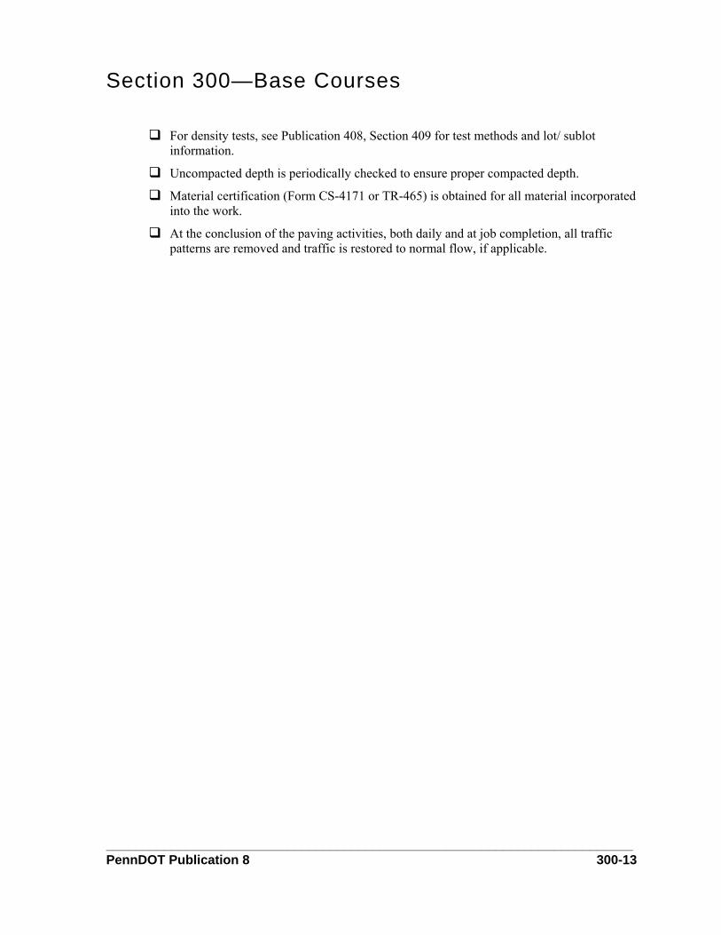
Section 300—Base Courses
For density tests, see Publication 408, Section 409 for test methods and lot/ sublot information.
Uncompacted depth is periodically checked to ensure proper compacted depth.
Material certification (Form CS-4171 or TR-465) is obtained for all material incorporated into the work.
At the conclusion of the paving activities, both daily and at job completion, all traffic patterns are removed and traffic is restored to normal flow, if applicable.
_________________________________________________________________________ PennDOT Publication 8 300-13
Section 300—Base Courses D. Aggregate Bituminous Base Course
This subchapter addresses the construction of a bituminous-treated, aggregate base course. If the course is placed on subgrade, the work includes the preparation of the subgrade.
References Publication 212 (Traffic Control)
Publication 408, Section 106 (Control of Material)
Publication 408, Section 108 (Performance and Progress)
Publication 408, Section 320 (Aggregate Bituminous Base Course)
Publication 408, Section 460 (Bituminous Tack Coat)
Publication 408, Section 702 (Bituminous Material)
Approved Mix Designs
Approved Bituminous Paving Quality Control Plans
Approved Traffic Control Plans
Material & Equipment Material for the work includes a class PG 64-22 or emulsified asphalt. The materials used to produce aggregate bituminous base course, such as bituminous material and coarse aggregate, must meet the requirements of Publication 408, Section 320.
All material must be from approved suppliers listed on the contractor’s approved material source of supply. The contractor must supply a copy of the bituminous material vendor’s bill of lading. The bill of lading should contain the information required by Publication 408, Section 702. The contractor must also supply a copy of the material certification (Form CS-4171) as specified in Publication 408, Section 106.
The material is hauled from the mix plant to the project, using vehicles that are tight, clean and have protective covers that are not torn nor have holes. In placing the base, the contractor uses a spreader, bituminous distributor, and compaction equipment.
The spreader used is adjustable, self-propelled, and capable of placing and screeding the base material without segregation. Rollers meeting the requirements of Publication 408, Section 108 are used to compact the base material to the required density.
If in-place mixing and spreading is done, the contractor needs a travel plant to place the material as outlined in Publication 408, Section 320. If the travel plant is not equipped to meter the liquid bituminous material, the contractor needs a bituminous distributor meeting the requirements of Publication 408, Section 460 to apply the bituminous material as specified in Publication 408, Section 320.
The inspector and the contractor need a thermometer or infrared temperature gun to check the temperature of the base material to ensure it is within specifications. The contractor may also
_________________________________________________________________________ PennDOT Publication 8 300-14
Section 300—Base Courses
need a nuclear gauge to check the compaction density of the base to ensure it meets the requirements specified in Publication 408, Section 320.
Construction Methods If batched at a mixing plant, the base material arrives on the project in hauling equipment meeting the requirements of Publication 408, Section 320, then end dumped into a spreader that meets the requirements of Publication 408, Section 320. All mixing and spreading of the base materials must also meet the requirements outlined in Publication 408, Section 320.
Using rollers that meet the requirements of Publication 408, Section 108, the contractor compacts the base material to the specifications outlined in Publication 408, Section 320.
If in-place mixing and spreading is done, the contractor needs a travel plant as specified in Publication 408, Section 320 to spread the base material. If the travel plant is not equipped to meter the liquid bituminous material, the contractor must use a distributor truck that meets the requirements of Publication 408, Section 460 to apply the bituminous material. The base material is mixed, compacted, and finished in a continuous operation, with finishing completed in daylight hours. The base material is then tested for density, surface tolerance, and depth as specified in Publication 408, Section 320.
The inspector in charge determines depth check locations using PTM 1 as specified in Publication 408, Section 320. For depth checks, the contractor drills a 150 mm (6 inches) diameter test hole at each location and the inspector measures the depth of the material. If the base is defective in depth, the inspector and the contractor follow the remediation procedures outlined in Publication 408, Section 320.
All work must be completed in strict accordance to the approved quality control plans.
Measuring & Payment Methods Aggregate bituminous base courses paid by the square meter (square yard). The area is field measured, with computations and payment shown on a PSA. The payment width should not exceed plan width unless authorized by a department representative.
Documentation On the PSA, document:
♦ Traffic control, if required, was set up per traffic control plans and Publication 213
♦ An item description and location
♦ Details of the paving operation, including materials used, tests performed, and equipment used
♦ Any of the statements in the Key Elements Checklist that can be included to provide details as to what occurred during the paving
♦ Payment. If applicable, indicate partial payments, as agreed to by the contractor, and reference any documentation that may have a schedule of payments
_________________________________________________________________________ PennDOT Publication 8 300-15

Section 300—Base Courses Key Elements Checklist
All outside agencies have been notified about the paving, as well as the time and date it is to occur.
A PennDOT approved copy of the approved mix design and approved paving quality control plan is on site.
All safety devices, such as flaggers, cones, lights, and warning signs, are in place as required.
Traffic patterns for maintenance and protection of traffic are in place per the approved project traffic control plan.
Water is sprayed uniformly through the aggregate prior to application of the emulsified pavement to ensure moisture content of 2% to 8% when tested with PTM 106.
Paperwork is on file for all bituminous material.
The temperature of the bituminous material is maintained when added to the mixture.
Distributors are calibrated.
Base courses of 150 mm (6 inches) or less are constructed in one layer.
If a depth of 150 mm (6 inches) or more is needed, construction is done with two lifts of equal compacted depth, with no layer less than 75 mm (3 inches) or more than 150 mm (6 inches) in depth.
Only necessary shaping and processing equipment is allowed to travel over the spread mixture.
Mixture that is contaminated or displaced is removed and replaced.
Base course is compacted to 100% of design density. If using asphalt cement, compact to at least 90% of the design density.
Tack coat is applied between layers.
Base course is mixed, compacted, and finished in a continuous operation during daylight hours.
One field density test is taken for each 2,500 m2 (3,000 square yards).
Depth is tested every 2,500 m2 (3,000 square yards).
Only necessary traffic is allowed on the base course.
Material certification (Form CS-4171) is obtained for all material incorporated into the work prior to payment.
Delivery tickets are obtained for all materials.
At the conclusion of the paving activities, both daily and at job completion, all traffic patterns are removed and traffic is restored to normal flow, if applicable.
_________________________________________________________________________ PennDOT Publication 8 300-16

Section 300—Base Courses E. Aggregate-Cement Base Course
This subchapter addresses the construction of a cement-treated aggregate base course. If placed on subgrade, construction includes preparing the subgrade as specified.
References Publication 212 (Traffic Control)
Publication 408, Section 106 (Control of Material)
Publication 408, Section 108 (Performance and Progress)
Publication 408, Section 320 (Aggregate Bituminous Base Course)
Publication 408, Section 321 (Aggregate Cement Base Course)
Publication 408, Section 460 (Tack Coat)
AASHTO T-134 (Moisture Density Relations of Soil Cement Mixtures)
Approved Mix Designs
Approved Concrete Paving Quality Control Plans
Approved Traffic Control Plans
Material & Equipment Material for the work includes Type C or better coarse aggregate and Class RS-1 of CRS-1 emulsified asphalt. The materials required to produce and to place the aggregate cement base course must meet the requirements outlined in Publication 408, Section 321. The cement and coarse aggregate are mixed either by a central mix plant or mixed in-place as specified in Publication 408, Section 321. Regardless, the materials must be mixed per the approved mix design. All materials are provided by a supplier listed on the contractor’s approved source of supply. All material used must be certified (Form CS-4171), as specified in Publication 408, Section 106.
Material mixed at a central mix plant must be transported to the project in vehicles meeting the requirement specified in Publication 408, Section 320.
The contractor needs a mechanical spreader that is adjustable, self-propelled, and capable of placing and screeding the base material without segregation. Rollers meeting the requirements of Publication 408, Section 108 are used to compact the base course as specified in Publication 408, Section 321.
The contractor also needs a distributor truck meeting the requirements of Publication 408, Section 460, to apply the bituminous cure as specified in Publication 408, Section 321.
Construction Methods For aggregate cement base course mixed at a central mix plant, the base course is delivered to the project site in hauling vehicles that meet the requirements of Publication 408, Section 320, then end dumped into the mechanical spreader. The contractor spreads the material to
_________________________________________________________________________ PennDOT Publication 8 300-17

Section 300—Base Courses
grade following the lift placement depth requirements specified in Publication 408, Section 321.
If the base course material is mixed in-place, the contractor spreads materials uniformly on the prepared area as specified in Publication 408, Section 321. Using a roller, the base is compacted to the required density specified in Publication 408, Section 321. The inspector determines optimum moisture content and maximum dry weight density in the field according to AASHTO T-134.
The contractor must mix, compact, and finish the base course in a continuous operation and complete the finishing in daylight hours. Compaction must be completed 3 hours after adding the water. After compaction and finishing, the contractor prepares the base and, using a distributor truck, applies the bituminous cure as specified in Publication 408, Section 321. The aggregate cement base course is tested for density, surface tolerance, and depth as specified in Publication 408, Section 321.
The inspector in charge determines depth check locations using PTM 1 as specified in Publication 408, Section 321. For depth checks, the contractor drills a 150 mm (6 inches) diameter test hole at each location and the inspector measures the depth of the material. If the base is defective in depth, the inspector and the contractor follow the remediation procedures outlined in Publication 408, Section 321.
All work must be completed in strict accordance to the approved quality control plans.
Measuring & Payment Methods Aggregate cement base courses are paid by the square meter (square yard). The area is field measured, with computations and payments shown on a PSA. The payment width should not exceed the plan width unless authorized by a Department Representative.
Documentation On the PSA, document:
♦ Traffic control, if required, was set up per traffic control plans and Publication 213
♦ An item description and location
♦ Details of paving operation, including material used, tests performed, and equipment used
♦ Any of the statements in the Key Elements Checklist that can be included to provide details as to what occurred during the paving
♦ Payment. If applicable, indicate partial payments, as agreed to by the contractor, and reference any documentation that may have a schedule of payments
Key Elements Checklist All outside agencies have been notified about the paving, as well as the time and date it is
to occur.
_________________________________________________________________________ PennDOT Publication 8 300-18

Section 300—Base Courses
A PennDOT approved copy of the approved mix design and approved paving quality control plan is on site.
All safety devices, such as flaggers, cones, lights, and warning signs, are in place as required.
Traffic patterns for maintenance and protection of traffic are in place per the approved project traffic control plan.
Delivery tickets are obtained for all materials.
Distributors are calibrated.
Aggregate and cement is mixed to prevent formation of cement balls when water is added.
Mixture is not spread or placed if the base area is excessively wet or frozen. Work is performed only if the temperature is 5 °C (40F) or above.
Base courses of more than 200 mm (8 inches) are constructed in two equal lifts, with each no less than 100 mm (4 inches) and no more than 200 mm (8 inches). A maximum compacted depth of 200 mm (8 inches) is allowed if the required compaction density can be attained for the full depth of each layer.
The loose base course mixture is compacted to at least 100% of the maximum dry mass density.
Base course mixing, compacting and finishing are done in a continuous operation during daylight hours.
If directed, surface scarifying and recompacting are done during the shaping operation to eliminate imprints left by equipment.
After completion, material is swept free of foreign material and moistening and rolling is done to integrate loose and dry surface material.
Bituminous material is applied at a rate of 0.45 liters/m2 to 0.68 liters/m2 (0.10 gallon per square yard to 0.15 gallon per square yard).
Sufficient moisture is maintained in the surface of the base course to prevent penetration of the bituminous material. If necessary, water is immediately applied to fill voids before applying bituminous materials.
The entire surface is covered to protect the base course.
Fine aggregate is spread if traffic is to be maintained before bituminous course is placed.
The base course is kept from freezing.
Density determinations are made as specified in Publication 408, Section 320. Sections that are below five pounds per cubic foot density are replaced.
Areas that are deficient in depth are surface scarified and additional material is placed.
_________________________________________________________________________ PennDOT Publication 8 300-19

Section 300—Base Courses
Material certification (Form CS-4171) is obtained for all material incorporated into the work.
At the conclusion of the paving activities, both daily and at the job completion, all traffic patterns are removed and traffic is restored to normal flow, if applicable.
_________________________________________________________________________ PennDOT Publication 8 300-20

Section 300—Base Courses F. Cold Recycled Bituminous Base Course, Cold-in-Place
This subchapter addresses the on-grade construction and material processing of a cold recycled bituminous base course that uses bituminous material combined with RAP, RAM, or virgin aggregates. Construction typically includes milling to an indicated depth, adding and mixing emulsified asphalt, placing, compacting, and testing.
References Publication 212 (Traffic Control)
Publication 242, Chapter 5
Publication 408, Section 106 (Control of Material)
Publication 408, Section 108 (Performance and Progress)
Publication 408, Section 341 (Cold Recycled Bituminous Base Course Cold In-Place)
Publication 408, Section 703 (Aggregate)
Approved Mix Designs
Approved Bituminous Paving Quality Control Plans
Approved Traffic Control Plans
Material & Equipment The materials used to produce the cold recycled base course must meet the requirements outlined in Publication 408, Section 341. The bituminous material would be one of the types listed in Publication 408, Section 341 and added to the reclaimed material per the approved mix design. All materials must be from the suppliers listed on the contractor’s approved material source of supply. The contractor must supply a copy of the material certification (Form CS-4171) as specified in Publication 408, Section 106.
The contractor uses equipment capable of milling the existing pavement, mixing and placing the material, and automatically metering liquids with a variation of not more than plus or minus 2% by weight of liquids.
The contractor needs rollers meeting the requirements of Publication 408, Section 108 to compact the base material to the requirements of Publication 408, Section 341. The contractor also needs to construct a test strip and check the density of the compacted base course as specified in Publication 408, Section 341.
Construction Methods The contractor takes samples of the reclaimed material and performs testing to establish the mix design. At least three weeks prior to the planned start of the mixture production, the mix design is submitted to the district materials engineer for review. Refer to Bulletin 27, Chapter 2 for procedures.
_________________________________________________________________________ PennDOT Publication 8 300-21

Section 300—Base Courses
The contractor uses equipment capable of processing the asphalt pavement material on grade, including the mixing and placing operations. The contractor uses a single train or multiple unit train of equipment to construct the cold recycled bituminous base course.
The inspector measures the milled depth and records at least one measurement on a PSA in each 2,500 m2 (3,000 square yards) to ensure that the pavement is milled to the depth indicated. Using a nuclear gauge, the contractor’s technician sets up a density control strip of approximately 500 m2 (600 square yards). Using the control strip, the technician determines the density required to compact the base course as specified in Publication 408, Section 341. If directed, the contractor checks the surface tolerance using a 3 m (10 feet) straight edge as specified in Publication 408, Section 341.
The inspector in charge determines depth check locations using PTM 1 as specified in Publication 408, Section 341. For depth checks, the contractor drills a 150 mm (6 inches) diameter test hole at each location and the inspector measures the depth of the material. If the base is defective in depth, the inspector and the contractor follow the remediation procedures outlined in Publication 408, Section 341.
The base course is cured and protected as specified in Publication 408, Section 341.
Measuring & Payment Methods Payment for cold in-place recycled bituminous base courses is in three parts.
The recycled bituminous base course is paid by the square meter (square yard). This area is field measured, with computations and payment shown on a PSA. The payment width would not exceed the plan width unless authorized by a department representative. Coarse aggregate is paid by the tonne (ton), for the total incorporated into the work and shown on the material delivery tickets. Bituminous material is paid in liter (gallon) for the total incorporated into the work, measured by an acceptable method
Documentation On the PSA, document:
♦ Traffic control, if required, was set up per traffic control plans and Publication 213
♦ An item description and location
♦ Details of paving operation, including material used, tests performed, and equipment used
♦ Any of the statements in the Key Elements Checklist that can be included to provide details as to what occurred during the paving
♦ Payment. If applicable, indicate partial payments, as agreed to by the contractor, and reference any documentation that may have a schedule of payments
Key Elements Checklist All outside agencies have been notified about the paving, as well as the time and date it is
to occur.
_________________________________________________________________________ PennDOT Publication 8 300-22
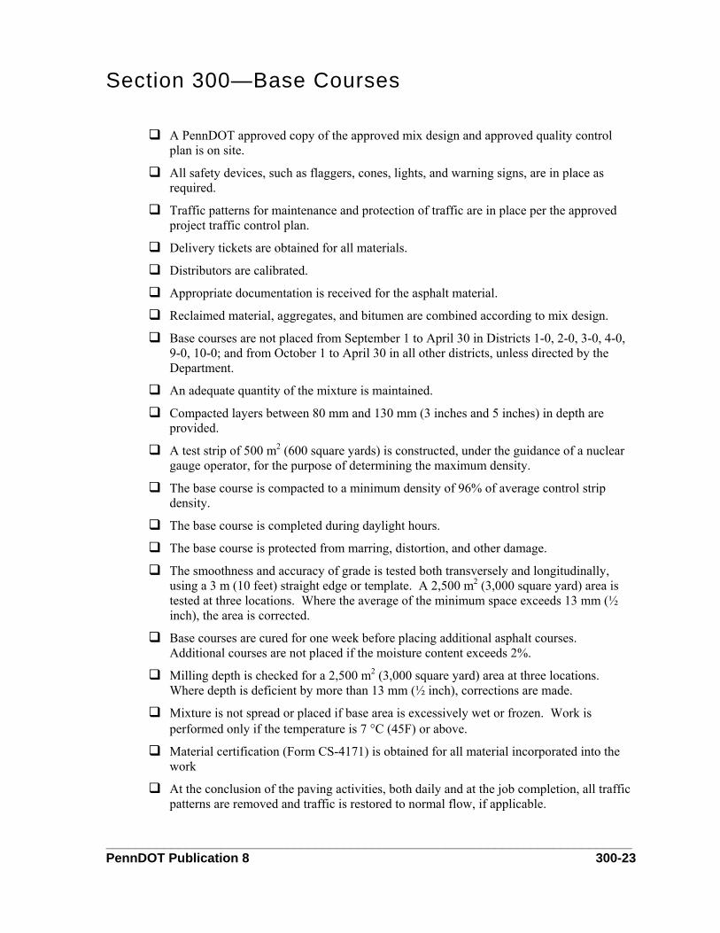
Section 300—Base Courses
A PennDOT approved copy of the approved mix design and approved quality control plan is on site.
All safety devices, such as flaggers, cones, lights, and warning signs, are in place as required.
Traffic patterns for maintenance and protection of traffic are in place per the approved project traffic control plan.
Delivery tickets are obtained for all materials.
Distributors are calibrated.
Appropriate documentation is received for the asphalt material.
Reclaimed material, aggregates, and bitumen are combined according to mix design.
Base courses are not placed from September 1 to April 30 in Districts 1-0, 2-0, 3-0, 4-0, 9-0, 10-0; and from October 1 to April 30 in all other districts, unless directed by the Department.
An adequate quantity of the mixture is maintained.
Compacted layers between 80 mm and 130 mm (3 inches and 5 inches) in depth are provided.
A test strip of 500 m2 (600 square yards) is constructed, under the guidance of a nuclear gauge operator, for the purpose of determining the maximum density.
The base course is compacted to a minimum density of 96% of average control strip density.
The base course is completed during daylight hours.
The base course is protected from marring, distortion, and other damage.
The smoothness and accuracy of grade is tested both transversely and longitudinally, using a 3 m (10 feet) straight edge or template. A 2,500 m2 (3,000 square yard) area is tested at three locations. Where the average of the minimum space exceeds 13 mm (½ inch), the area is corrected.
Base courses are cured for one week before placing additional asphalt courses. Additional courses are not placed if the moisture content exceeds 2%.
Milling depth is checked for a 2,500 m2 (3,000 square yard) area at three locations. Where depth is deficient by more than 13 mm (½ inch), corrections are made.
Mixture is not spread or placed if base area is excessively wet or frozen. Work is performed only if the temperature is 7 °C (45F) or above.
Material certification (Form CS-4171) is obtained for all material incorporated into the work
At the conclusion of the paving activities, both daily and at the job completion, all traffic patterns are removed and traffic is restored to normal flow, if applicable.
_________________________________________________________________________ PennDOT Publication 8 300-23
Section 300—Base Courses G. Cold Recycled Bituminous Base Course, Central Plant
This subchapter addresses the construction of a cold recycled bituminous base course, central plant mix, using a combination of RAP, RAM, or virgin aggregates, mixed with bituminous material in a continuous or batch type mixer.
References Publication 212 (Traffic Control)
Publication 242, Chapter 5
Publication 408, Section 106 (Control of Work)
Publication 408, Section 108 (Performance and Progress)
Publication 408, Section 341 (Cold Recycled Bituminous Base Course, Cold in Place)
Publication 408, Section 342 (Cold Recycled Bituminous Base Course, Central Plant Mix)
Bulletin 27, Chapter 2
Approved Quality Control Plans
Approved Traffic Control Plans
Approved Mix Design
Material & Equipment The materials used to produce the cold recycled base course must meet the requirements outlined in Publication 408, Section 341. The bituminous material would be one of the types listed in Publication 408, Section 341 and added to the reclaimed material per the approved mix design. All materials must be from the suppliers listed on the contractor’s approved material source of supply. The contractor must supply a copy of the material certification (Form CS-4171) as specified in Publication 408, Section 106.
To haul the material from the central mix plant, the contractor must use vehicles that are clean, tight, and if required, have protective covers. The contractor needs mixing equipment that conforms to Publication 242, Chapter 5 and is capable of mixing the pulverized reclaimed material and additive into a homogeneous mixture.
A mechanical spreader is used to place the material on a prepared surface to a uniform depth conforming to Publication 242, Chapter 5. Rollers meeting the requirements of Publication 408, Section 108 are used to compact the base course to the required density. The contractor also needs a nuclear gauge to establish and check the density of the compacted base course as specified in Publication 408, Section 341.
Construction Methods The contractor takes samples of the reclaimed material and performs testing to establish the mix design as specified in Publication 408, Section 341. At least three weeks before the planned start of mixture production, the mix design must be submitted to the district materials engineer for review.
_________________________________________________________________________ PennDOT Publication 8 300-24
Section 300—Base Courses
The base course material is mixed at the central mix plant per the approved mix design and delivered to the project in vehicles meeting the requirements of Publication 408, Section 342. The material is then end dumped from the hauling vehicles into the mechanical spreader.
The spreader is placed the base material to the indicated compacted depth. After placement rollers are used to compact the base. Using a nuclear gauge, the contractor’s technician sets up a density control strip of approximately 500 m2 (600 square yards). Using the control strip, the technician determines the density required to compact the base course as specified in Publication 408, Section 341.
The base course is cured and protected, and the surface is tested, as specified in Publication 408, Section 341. At the direction of the inspector, the contractor tests the base course depth as specified in Publication 408, Section 342.
The inspector in charge determines depth check locations using PTM 1 as specified in Publication 408, Section 342. For depth checks, the contractor drills a 150 mm (6 inches) diameter test hole at each location and the inspector measures the depth of the material. If the base is defective in depth, the inspector and the contractor follow the remediation procedures outlined in Publication 408, Section 342.
Measuring & Payment Methods Payment for central plant mixed cold recycled bituminous base courses is in three parts.
The recycled bituminous base course is paid by the square meter (square yard). The area is field measured, with computations and payment shown on a PSA. The payment for width would not exceed plan width unless authorized by a department representative. Coarse aggregate is paid by the tonne (ton) for the amount incorporated into the work, as shown on the delivery tickets. Bituminous material is paid in liter (gallon) for the amount incorporated into the work as measured by an acceptable method.
Documentation On the PSA, document:
♦ Traffic control, if required, was set up per traffic control plans and Publication 213
♦ An item description and location
♦ Details of paving operation, including material used, tests performed, and equipment used
♦ Any of the statements in the Key Elements Checklist that can be included to provide details as to what occurred during the paving
♦ Payment. If applicable, indicate partial payments, as agreed to by the contractor, and reference any documentation that may have a schedule of payments
Key Elements Checklist All outside agencies have been notified about the paving, as well as the time and date it is
to occur.
_________________________________________________________________________ PennDOT Publication 8 300-25
Section 300—Base Courses
A PennDOT approved copy of the approved mix design and approved quality control plan is on site.
All safety devices, such as flaggers, cones, lights, and warning signs, are in place as required.
Traffic patterns for maintenance and protection of traffic are in place per the approved project traffic control plan.
Mixture is transported in clean, tightly sealed vehicles.
Reclaimed material, aggregates, and bitumen are combined according to mix design.
Base courses are not placed from September 1 to April 30 in Districts 1-0, 2-0, 3-0, 4-0, 9-0, 10-0; and from October 1 to April 30 in all other districts, unless directed by the Department.
An adequate quantity of the mixture is maintained.
Compacted layers between 80 mm to 130 mm (3 inches to 5 inches) in depth are provided.
A test strip of 500 m2 (600 square yards) is constructed, under the guidance of a nuclear gauge operator, for the purpose of determining the maximum density.
The base course is compacted to a minimum density of 96% of average control strip density.
The base course is completed during daylight hours.
The base course is protected from marring, distortion, and other damage.
The smoothness and accuracy of grade is tested both transversely and longitudinally, using a 3 m (10 feet) straight edge or template. A 2,500 m2 (3,000 square yard) area is tested at three locations. Where the average of the minimum space exceeds 13 mm (½ inch), the area is corrected.
Base courses are cured for one week before placing additional asphalt courses. Additional courses are not placed if the moisture content exceeds 2%.
Milling depth is checked at one location every 2,500 m2 (3,000 square yards). Where depth is deficient by more than 13 mm (½ inch), the material is removed and replaced.
Mixture is not spread or placed if base area is excessively wet or frozen. Work is performed only if the temperature is 7 °C (45F) or above.
Material certification (Form CS-4171) is obtained for all material incorporated into the work.
At the conclusion of the paving activities, both daily and at job completion, all traffic patterns are removed and traffic is restored to normal flow, if applicable.
_________________________________________________________________________ PennDOT Publication 8 300-26
Section 300—Base Courses H. Asphalt Treated Permeable Base Course
This subchapter addresses the construction of an asphalt treated permeable base course (ATPBC) on a prepared surface. If placed on subgrade, this work includes the preparation of the subgrade.
References Publication 212 (Traffic Control)
Publication 408, Section 106 (Control of Work)
Publication 408, Section 360 (Asphalt Treated Permeable Base Course)
Publication 408, Section 702 (Bituminous Material)
Publication 408, Section 703 (Aggregates)
Approved Bituminous Paving Quality Control Plans
Approved Traffic Control Plans
Approved Bituminous Mix Design
Material & Equipment Materials for the work include approved asphalt cement, Class PG 64-22, as well as coarse and fine aggregates. The materials used to produce asphalt treated permeable base course must meet the requirements outlined in Publication 408, Section 360. These include asphalt cement class PG 64-22, coarse aggregate Type A or Type B, fine aggregate Type A or Type B, hydrated lime, and a heat stable anti-stripping additive. These materials must be mixed as specified in Publication 408, Section 360 and approved mix designs. All material must be from the suppliers listed on the contractor’s approved source of supply. The contractor must supply a copy of the material certification (Form CS-4171) for the materials used as specified in Publication 408, Section 106 prior to making payment for the work.
The material is hauled to the project site in vehicles (such as dump trucks) that are clean, tightly sealed, and have protective covers.
The contractor uses a paver that is self contained and power propelled, with activated screeds or activated strike off assemblies and automatic screed controls. The paver should be capable of spreading and finishing the mixture to the width and depth indicated, and meet all other requirements specified in Publication 408, Section 401. The contractor can also use a mechanical spreader to place the base course. Steel wheel rollers, with a manufacturer’s certified mass weight of 7 tonnes to 9 tonnes (8 tons to 10 tons) as specified in Publication 408, Section 360, are used to compact the base.
The contractor and the inspector need a calibrated thermometer or an infrared temperature gun to check the temperature of the material when it arrives on the project to ensure it is within specifications for the PG 64-22 asphalt cement and Publication 408, Section 360.
_________________________________________________________________________ PennDOT Publication 8 300-27

Section 300—Base Courses Construction Methods
The base material is hauled to the project site in vehicles meeting the requirement of Publication 408, Section 401, then end dumped into the bituminous paver or mechanical spreader. At this time, the inspector checks the material temperature to ensure it is within specifications.
A paver or mechanical spreader places the material, using automatic screed controls to provide the indicated cross slope and depth and automated sensors to control the profile and transverse grade. The material is placed in maximum 100 mm (4 inches) compacted lifts and is allowed to cool to 38 °C (100F) before placing the next layer or pavement course.
After the material has sufficiently cooled, the contractor rolls the base with a steel wheel roller in static mode as specified in Publication 408, Section 360 to prevent shoving or lateral movement. The base course is compacted until it supports the weight of the paving equipment and is sufficiently stable to avoid shoving or lateral movement.
The surface tolerance is checked with a 3 m (10 feet) straight edge as specified in Publication 408, Section 360. The base course is protected and the asphalt treated base course is checked for depth as specified in Publication 408, Section 360.
The inspector in charge determines depth check locations using PTM 1 as specified in Publication 408, Section 360. For depth checks, the contractor drills a 150 mm (6 inches) diameter test hole at each location and the inspector measures the depth of the material. If the base is defective in depth by 13 mm (1/2 inch) or more, the inspector and the contractor follow the remediation procedures outlined in Publication 408, Section 360.
Measuring & Payment Methods Asphalt treated permeable base courses are paid by the square meter (square yard). The area is field measured, with computations and payment shown on a PSA. The width payment would not exceed the plan width unless authorized by a department representative.
Documentation On the PSA, document:
♦ Traffic control, if required, was set up per traffic control plans and Publication 212
♦ An item description and location
♦ Details of paving operation, including material used, tests performed, and equipment used
♦ Any of the statements in the Key Elements Checklist that can be included to provide details as to what occurred during the paving
♦ Payment. If applicable, indicate partial payments, as agreed to by the contractor, and reference any documentation that may have a schedule of payments
_________________________________________________________________________ PennDOT Publication 8 300-28
Section 300—Base Courses Key Elements Checklist
All outside agencies have been notified about the paving, as well as the time and date it is to occur.
A PennDOT approved copy of the approved mix design and approved quality control plan is on site.
All safety devices, such as flaggers, cones, lights, and warning signs, are in place as required.
Traffic patterns for maintenance and protection of traffic are in place per the approved project traffic control plan.
ATPBC is not placed on surfaces that are frozen or where the surface and air temperature is below 2 °C (35F).
The mixture is placed in compacted lifts of a maximum of 100 mm (4 inches).
Automated sensors are used to control transverse grade and profile.
Lifts are allowed to cool to 38 °C (100F) before placing the next lift.
Vibratory roller in operated in static mode only.
A minimum of two roller passes are used to compact material. Compaction occurs only when the mat has cooled enough to prevent shoving or lateral movement.
Aggregate is not crushed with compaction.
ATPBC is placed so that is overlaps the edge of previously placed adjacent lanes by 25 mm to 50 mm (1 inch to 2 inches).
At the end of the day and for any interruption of 30 minutes or more, a vertical bulkhead of full depth is installed.
The finished surface is tested at locations that appear irregular and at transverse joints and paving notches. To do so, a 3 m (10 feet) straightedge is held in contact with the surface and parallel to the road centerline. In successive positions, the pavement surface is tested from one side to the other. The straight edge is advanced to the next location by moving it along the pavement centerline by not more than 1.5 m (5 feet). Irregularities of more than 13 mm (½ inch) are corrected by loosing surface and removing or adding mixture.
One test core of 150 mm (6 inches) is drilled for every 2,500 m2 (3,000 square yards) of compacted base course. Sections that are deficient by 13 mm (½ inch) or more are removed and replaced.
With the exception of work-related traffic, traffic is not permitted on ATPBC.
The surface of the course is protected from damage.
ATPBC deficient in surface tolerance, depth, or asphalt content is removed and replaced.
_________________________________________________________________________ PennDOT Publication 8 300-29

Section 300—Base Courses
Material certification (Form CS-4171) is obtained for all material incorporated into the work.
At the conclusion of the paving activities, both daily and at job completion, all traffic patterns are removed and traffic is restored to normal flow, if applicable.
_________________________________________________________________________ PennDOT Publication 8 300-30

Section 350—Subbases
Table of Contents 1. Subbase....................................................................................................................................350-1
PennDOT Publication 8 350-i

Section 350—Subbases
This Page Left Intentionally Blank
PennDOT Publication 8 350-ii

Section 350—Subbases
PennDOT Publication 8 350-1
1. Subbase The chapter addresses the preparation of subgrade and the compacted aggregate subbase.
References Publication 408, Section 210 (Subgrade)
Publication 408, Section 320 (Aggregate-Bituminous Base Course)
Publication 408, Section 350 (Subbase)
Publication 408, Section 703 (Aggregate)
Bulletin 14 (Approved Aggregate Producers)
Approved Source of Supply
Standard Drawings
Material Certifications
Approved Traffic Control Plans
Material & Equipment The aggregate used for subbases is Type C, Type 2A, or open graded subbase (OGS) as specified in Publication 408, Section 703. The aggregate must be supplied by a supplier listed in Bulletin 14 and on the contractor’s approved material source of supply. Prior to payment being made, the contractor must provide a copy of the material certification for the aggregate (Form CS-4171) as specified in Publication 408, Section 106.
The contractor uses a spreader and steel-wheel roller in constructing the subbase. To place the base material, the contractor needs an adjustable, self-propelled mechanical spreader capable of placing and screeding the base material without segregation. The contractor may use an autograder to trim the subbase to grade. Rollers meeting the requirements of Publication 408, Section 108, are used to compact the base material.
A nuclear gauge may be used to check the compaction density of the subbase. If more than 20 percent of the material is retained on the 18 mm (3/4 inch) sieve, the compaction is checked manually for non-movement under compaction, with the results recorded on a Report on

Section 350—Subbases
PennDOT Publication 8 350-2
Compaction Density-Nonmovement (Form TR-478A). Either the onsite materials inspector or District materials personnel can provide direction as to what method is appropriate for checking compaction of the subbase.
Construction Methods The contractor prepares the subgrade as specified in Publication 408, Section 210 and to plan grades. The subbase material is delivered to the project site from the approved supplier in dump trucks and is end-dumped into an approved spreader.
Using the spreader, the contractor places the subbase material to the depth and width requirements shown on the plan and for the indicated type of pavement as specified in Publication 408, Section 350. After the subbase material is placed, it is compacted as specified in Publication 408, Section 350 with rollers meeting the requirements of Publication 408, Section 108.
If the subbase material meets the gradation requirements specified in Publication 408, Section 350, the contractor’s technician tests the compaction density of the compacted subbase as specified. The completed subbase is checked for surface tolerance and depth, and is maintained as specified in Publication 408, Section 350. If the depth is deficient, the defective area is scarified, additional materials are placed and blended with those in place, and the area is re-compacted.
Measuring & Payment Methods This item is usually paid by the square meter (square yard), based on field measurements. For some special cases subbase may also be paid by the cubic meter (cubic yard) or the metric ton (ton).
Payment for the subbase is 75% of the estimated material payment amount until subsequent pavement is placed. This usually occurs for subbase paid for by the square yard. Once the subbase is covered with the next pavement course the remaining 25% is paid.
Documentation On the PSA, document:
♦ That traffic control, if required, was set up as per the traffic control plan or Publication 212
♦ An item description and location
♦ Details of the paving operation, including materials used, tests performed, and equipment used
♦ Any of the statements in the Key Elements Checklist that can be included to provide details as to what occurred during the paving
♦ Payment. If applicable, indicate partial payments, as agreed to by the contractor, and reference any documentation that explains the details of the partial payments
Section 350—Subbases
PennDOT Publication 8 350-3
Key Elements Checklist All safety devices, such as flaggers, cones, lights, and warning signs, are in place as
required.
Traffic patterns for the maintenance and protection of traffic are in place per the approved project traffic control plan.
Subgrade is prepared as specified in Publication 408, Section 210.
Subbase is not placed on soft, muddy, or frozen areas.
Subbase depth and elevation are controlled per plans and specifications.
Material is placed on the subgrade without segregation.
For rigid pavement, a course of 2A aggregate is placed to a minimum compacted depth of 75 mm (3 inches) directly on the subgrade. A course of OGS aggregate is placed on top of the 2A aggregate to a minimum compacted depth of 100 mm (4 inches). (The required depth of subbase is shown on the typical sections of the contract drawings.)
For flexible pavement, each layer of 2A aggregate is placed to a compacted depth no greater than 200 mm (8 inches). (The required depth of subbase is shown on the typical sections of the contract drawings.)
The subbase is compacted and maintained at least 460 m (1,500 linear feet) in advance of placing the succeeding paving course. The 2A aggregate subbase is compacted to at least 100% of dry-mass density.
The in place density is determined at specified locations. The project materials technician or designated District materials technician is consulted for nuclear density requirements. Locations for density tests are determined using PTM 1.
Depth is tested at each density location.
If subbase is deficient by 13 mm (½ inch) or more from the required depth, it is considered defective and must be either corrected or removed and replaced.
Traffic is not permitted on subbase constructed of OGS aggregate. Traffic is minimized or eliminated from any subbase until it is checked and approved for the placement of base courses.
If the subbase was open to weather for 60 days or more, it is retested for surface irregularities and depth.
At the conclusion of the construction activities, both daily and at job completion, all traffic patterns are removed and traffic is restored to normal flow, if applicable.

Section 350—Subbases
PennDOT Publication 8 350-4
This Page Left Intentionally Blank
Section 400—Flexible Pavement
Table of Contents 1. Bituminous Paving with Conventional & Superpave Mixture Design, Construction of
Plant-Mixed Hot Mix Asphalt (HMA) Courses, Standard and Restricted Performance Specification (RPS) ...............................................................................................................400-1
2. Evaluation of Bituminous Pavement Ride Quality and Payment of Incentive....................400-10 3. Bituminous Tack Coat .........................................................................................................400-12 4. Bituminous Prime Coat .......................................................................................................400-14 5. Heavy-Duty Membranes......................................................................................................400-16 6. Asphalt Joint and Crack Sealing..........................................................................................400-18 7. Bituminous Seal Coat & Bituminous Seal Coat Using Precoated Aggregate;
Bituminous Surface Treatment & Bituminous Surface Treatment Using Pre-Coated Aggregate.............................................................................................................................400-20
8. Slurry Seal ...........................................................................................................................400-23 9. Removal of Existing Surface Course...................................................................................400-25 10. Milling of Bituminous Pavement Surface, Profile Milling, Variable Depth .......................400-27 11. Preparation of Bases ............................................................................................................400-29 12. Operation of Paver...............................................................................................................400-31
A. Checking Thickness of Mat .......................................................................................400-32 13. Hand Spreading and Finishing.............................................................................................400-34 14. Compacting Binder and Wearing Courses ..........................................................................400-36 15. Constructing Longitudinal Joints.........................................................................................400-38 16. Constructing Transverse Joints............................................................................................400-40 17. Testing HMA.......................................................................................................................400-42 18. Protection of Surface Courses .............................................................................................400-44 19. Shoulder Construction .........................................................................................................400-45
PennDOT Publication 8 400-i

Section 400—Flexible Pavement
This Page Left Intentionally Blank
PennDOT Publication 8 400-ii
Section 400—Flexible Pavement
1. Bituminous Paving with Conventional & Superpave Mixture Design, Construction of Plant-Mixed Hot Mix Asphalt (HMA) Courses, Standard and Restricted Performance Specification (RPS) This chapter addresses bituminous paving operations with conventional mixture design and Superpave mixture design, both standard and RPS, using plant mixed HMA.
References Publication 213 (Traffic Control)
Publication 408, Section 108 (Character of Workers, Methods and Equipment)
Publication 408, Section 401 (Bituminous Paving)
Publication 408, Section 409 (Superpave Mixture Design, Standard and RPS Construction of Plant Mixed HMA Courses)
Publication 408, Section 420 (Bituminous Wearing ID2)
Publication 408, Section 422 (Bituminous Wearing FJ-1 and FJ-1C)
Publication 408, Section 424 (Bituminous Wearing ID3)
Publication 408, Section 430 (Bituminous Wearing FB-2)
Publication 408, Section 439 (Bituminous Wearing FB-1)
Publication 408, Section 421 (ID2 Standard)
Publication 408, Section 430 (Asphalt Cement Class PG 64-22 or 58-28 for ID2 binder for FB-2 binder)
Publication 408, Section 430 (Asphalt Cement for FB-1, excluding Class PG 64-22 and 58-28)
Publication 408, Section 431 (FB-2)
Publication 408, Section 440 (FB-1)
Publication 408, Section 460 (Bituminous Tack Coat)
Publication 408, Section 702 (Bituminous Material)
PennDOT Publication 8 400-1
Section 400—Flexible Pavement Publication 408, Section 703 (Coarse Aggregate)
RC Standard 28M (Overlay Transitions and Paving Notches)
Publication 2, Project Office Manual, Part C, Section 4 (Flexible Pavements)
Approved Quality Control Plan
Approved Bituminous Mix Designs
PTM 1 (Probability Sampling)
PTM 402 (Determining the Density of In-Place Construction Material Using a Nuclear Gauge)
PTM 403 (Determining In-Place Density of Bituminous Concrete Using Electrical Impedance Measurement Methods)
PTM 737 (Measuring the Thickness of Bituminous Concrete Base Course)
PTM 746 (Sampling Bituminous Mixtures)
PTM 747 (Determination of Distributor Application Rate in the Field)
RC Standard 28M (Overlays Transitions and Paving Notches)
Publication 35 (Bulletin 15), Approved Construction Materials
Publication 37 (Bulletin 25), Specifications of Bituminous Materials
Material & Equipment The type and class of bituminous material is furnished as required by the applicable pavement section (Aggregates Coarse and Fine) conforming to gradations of Table A, Section 703 and Table B, Section 703 of Publication 408. Bituminous material is mixed at a batch or drum plant, usually a commercial plant or occasionally a portable plant set up on a project. The bituminous material is produced in accordance with the mix design submitted by the producer and approved by the district materials engineer as well as the plant quality control plan. The bituminous producer will also submit a quality control plan for approval from the district materials engineer.
When material is delivered to the project, each truck will have a delivery ticket (either computer generated or prepared by hand) noting items such as the state route, county or district, material type, date and time, quantity of material on the load, cumulative quantity of material delivered, and truck number. At the conclusion of the paving day, the driver of the last truck of that day or the first truck the next day should provide the inspector material certification (Form CS-4171) for the material incorporated in the paving.
In laying the pavement, the contractor utilizes bituminous pavers with activated screeds and automatic screed controls. Bituminous hauling equipment should be tightly sealed with covers of sufficient size and quality to protect the intire load. From October 1 to April 30, haul trucks must have insulation on all sides of the truck body, a double walled truck body or a heated truck body. Rollers must be steel wheel, pneumatic tire, or vibratory, meeting the requirements of Publication 408, Section 108 and operated according to the manufacturer’s recommendations.
PennDOT Publication 8 400-2
Section 400—Flexible Pavement The contractor’s technician will determine the number and size of rollers to be used to achieve required compaction, by establishing a rolling pattern as specified in PTM 402 or PTM 403. By employing proper roller size, speed, and amplitude frequency, shoving and cracking of the pavement should be eliminated.
Inspectors must have a thermometer or infrared temperature gun capable of reading temperatures up to 205 °C (400F) to check the temperature of the bituminous material when it is discharged from the truck to the paver hopper to ensure that the material is within specifications.
A 1,200 mm (4 feet) level is also required to check cross slope of the new pavement to ensure it meets plan typicals and cross sections. A 3 m (10 feet) straightedge is also required to check the surface of the pavement and to check the profile at construction joints. This will ensure a smooth ride and that the surface is within the tolerances noted in Publication 408, Sections 401 and 409.
The contractor may use a roto mill to mill paving notches and paving transitions in existing pavements per RC Standard 28M. The contractor uses a self-propelled paver with activated screeds and automatic screed controls capable of producing a finished surface of specified evenness. The texture must meet the requirements of Publication 408, Sections 401 and 409.
Hand tools are used to place blacktop material in locations inaccessible to pavers. Shovels and lutes are used for moving and leveling blacktop placed by hand. The contractor is not allowed to use rakes when placing blacktop. Using rakes will cause segregation of the bituminous mixture.
Overlays
Overlays consist of a placing a binder or wearing course over existing pavements, as indicated by the contract drawings and specifications. Specifications for materials used in overlays are listed in Publication 408, Sections 401 and 409, depending on the type of material required by contract drawings.
Scratch & Leveling Courses
A scratch course is used to adjust an existing bituminous roadway to a new cross slope. The cross slope is changed by placing a course of bituminous pavement with the depth varying transversely across the roadway. When viewing a cross section in the plans, a scratch course will look like a wedge.
A leveling course is used to bring and uneven roadway surface to a consistent grade by filling in depressions such as wheel ruts.
Due to the usually thin depth of scratch and leveling courses, the bituminous mixture is made of a fine aggregate.
Patching
The contractor uses a concrete saw to cut the limits of existing pavement where the patch is to be placed. Excavating equipment, such as a backhoe, grade-all, and track excavator, is used
PennDOT Publication 8 400-3

Section 400—Flexible Pavement to remove material. Dump trucks haul the excavated material to an approved waste area. A wacker or vibratory plate might be used to compact the subbase if it is disturbed. A roto milling machine can also be used to remove existing pavement in the patch area.
The contractor uses a distributor to apply the tack coat to the vertical edges of patches. The distributor must meet the requirements of Publication 408, Section 460. A mechanical paver may be needed for larger asphalt patches. The paver must meet all the requirements of Publication 408, Sections 401 and 409.
For smaller asphalt patches, the contractor may use hand tools, such as square shovels, lutes, and a straightedge. Rollers and hand tampers are used to compact material. Rollers must meet the requirements of Publication 408, Section 108.
Construction Methods Traffic control is set up according to the project traffic control plan and Publication 213. The pavement surface is cleaned as directed and according to Publication 408, Section 401.
A tack coat is applied according to Publication 408, Section 460 specifications. Vertical faces of longitudinal and horizontal joints, curbs, and gutters are painted with asphalt.
The contractor sets the paver to the proper cross slope and depth, and the strike off screed is heated.
The bituminous material is discharged from dump trucks or transfer units into the paver hopper. The paving joint (transverse/longitudinal) is checked with a 3 m (10 feet) straight edge to ensure a smooth transition (as indicated in Publication 408, Sections 401 and 409). The paver then places the bituminous material at the required pavement depth and cross slope.
The contractor’s certified nuclear technician, using a nuclear gauge or electrical impedance gauge, establishes a rolling pattern for density as specified in PTM 402. The number of rollers, as well as the number of passes each roller will make, is determined by the rolling pattern.
Prior to placing another course of bituminous material, the previously placed course is cleaned and the vertical edges of the existing pavement are tack coated. If the base course is an existing pavement, a tack coat is applied to the entire surface.
After the pavement is placed, the contractor and the inspector check the depth and cross slope directly behind the paver. Once rolling begins, the contractor’s technician, using a nuclear gauge to ensure proper density, establishes a rolling pattern as specified in PTM 402. The rolling pattern determines the number of rollers, the size of the rollers, and the number of roller passes required to achieve the required density. Once paving is complete, cores are taken in locations established by the inspector.
The new pavement surface temperature must be below 60 °C (140F) before opening to traffic and equipment. To check for surface smoothness, the straightedge is slid along the pavement
PennDOT Publication 8 400-4
Section 400—Flexible Pavement surface, not exceeding half its length at a time. To check for smoothness at a construction joint, the straightedge is laid longitudinally across the joint.
Scratch & Leveling Courses
The contractor uses the same methods for placement of scratch and leveling courses as with other courses of blacktop. However, the compaction methods for these courses are different. In order to compact these thin, inconsistent layers of blacktop, the contractor will use a pneumatic roller. A pneumatic roller uses air-filled rubber tires instead of a steel drum for compacting the lift of blacktop.
Bituminous Patching
The areas to be patched are laid out by a department representative.
The limits of the area to be patched are cut with a concrete saw if excavating equipment is to be used for material removal. The use of a concrete saw ensures a vertical edge on the patches and protects the remaining pavement from damage that might be caused by excavating equipment. If a roto milling machine is used to remove the pavement, it will also create a vertical edge.
The material from the patch area is then excavated. The subbase is repaired and compacted, if necessary. The vertical edges of the pavement are tacked using an approved bituminous material as listed in Publication 408, Section 460. The asphalt material required by project plan documents is placed according to the contractor’s approved quality control plan and requirements of applicable sections of Publication 408. Bituminous material is compacted as required by Publication 408, Sections 401 and 409 and according to the contractor’s approved quality control plan. The density of the bituminous material is checked either by the contractor’s technician (using a nuclear gauge), or is accepted by visual non-movement under the compaction equipment, as noted in Publication 408, Section 401 and 409. The newly-placed surface is not opened to traffic until the surface temperature is below 60 °C (140F).
Measuring & Payment Methods Payment for tonnage items is based on the amount of material incorporated into the work, using weight noted on the delivery tickets received from the bituminous trucks. Square meter (square yard) items are field measured; computations must be shown on a PSA or spreadsheet. Yield tests are performed to check the amount of material placed.
Square meter (square yard) items can be paid progressively, based on construction station lengths. The final payment, adjusted for progress payments, is based on field measurements and computations. The pavement width measurement should not exceed plan width unless authorized by a department representative. The final payment, adjusted for progress payments, is based on field measurements and computations. The pavement width measurement should not exceed the plan width unless authorized by a department representative.
Asphalt patches can be paid by the square meter (square yard), including sawing and excavating or the excavation and patching material can be paid as individual units, depending
PennDOT Publication 8 400-5
Section 400—Flexible Pavement on contract specifications. If asphalt patching is paid in square meter (square yard), the patches are field measured and computations are shown on a PSA. If paid in units (e.g., Class 1 or 1B excavation), the excavated areas are field measured, with computations made in cubic meter (cubic yard) and payments included on a PSA. Bituminous material is paid by the tonne (ton), using the amount of material incorporated into the work as recorded on the delivery tickets.
Documentation On the PSA, document:
♦ That traffic control is set up according to the project traffic control plan or Publication 213
♦ Manpower and equipment used in the operation
♦ Material temperatures taken
♦ Results of a yield test and computations
♦ Affirmation of the tack application rate per PTM 747
♦ Witness to the rolling pattern being established per PTM 402 or PTM 403 by the contractor’s technician
♦ Verification of loose depth checks by both the inspector and the contractor
♦ Construction stations where material was placed and the type and amount of material placed
♦ Cross slope checks before and after compaction, as well as the width of pavement before compaction
♦ Station-to-station of newly-placed pavement, which lane was paved, and the direction
♦ Identification of core and loose box sample locations, and verification of the contractor taking them, per Publication 408, Sections 401 and 409, using PTM 1. (Occasionally, these computations are kept in a field survey book.)
♦ Verification of the surface temperature of the newly-placed pavement, confirming that the temperature was below 60 °C (140F) before it was opened to hauling equipment and traffic
♦ Any problems with the pavement placement, including location and a description of the problem
♦ Weather conditions at time of paving, especially early and late in the season
♦ That proper hauling equipment was used to deliver material to the job site
♦ That the surface was clean, dry, and approved before paving
♦ That the tack coat was applied according to Publication 408 specifications and that the application rate was per PTM 747
PennDOT Publication 8 400-6

Section 400—Flexible Pavement
♦ Material temperature checks taken and documented on delivery tickets
♦ That the paver is equipped with the proper screed controls
♦ That the existing pavement surface to be overlaid was prepared per Publication 408, Sections 401 and 409
♦ That the approved mix design and quality control plan for bituminous paving has been obtained
♦ That the existing pavement surface was prepared according to Publication 408, Sections 401 and 409, and the name of the approving inspector
♦ That material was compacted by a pneumatic tire roller to visual non-movement and recorded on Form TR-478A (scratch & leveling courses)
♦ The removal of existing pavement from the patch area and where the excavated material was taken (pavement patching)
♦ Required subbase repairs, if required
♦ How material was compacted and that the compaction was checked either with a nuclear gauge by the contractor’s technician or verified by visual non-movement under compaction equipment
♦ Payment computations with measurements taken in the field
Key Elements Checklist Traffic control is set up according to the project traffic control plan or per Publication
213.
Material testing locations are calculated using PTM 1.
Fuel oil or other solvents that may damage the paving material are not carried on the paving equipment.
The mix design and temperature of the material in the truck is verified at the beginning of paving operation.
Verify paver is set to proper cross slope and depth prior to paving.
Paver screed must be heated prior to paving.
Cross slope at the beginning of paving is checked to ensure it conforms to typical sections.
Core sample locations are identified and witnessed as taken.
Course thickness is measured from density cores.
Loose box samples are collected.
Yield on tonnage projects is regularly monitored; yield on square yard projects is randomly monitored.
Segregation, dust balls, mat cracking, and uncoated aggregate are randomly monitored.
PennDOT Publication 8 400-7
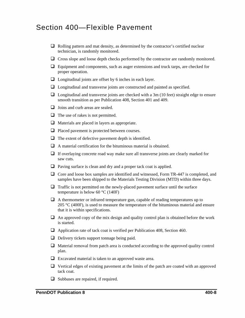
Section 400—Flexible Pavement
Rolling pattern and mat density, as determined by the contractor’s certified nuclear technician, is randomly monitored.
Cross slope and loose depth checks performed by the contractor are randomly monitored.
Equipment and components, such as auger extensions and truck tarps, are checked for proper operation.
Longitudinal joints are offset by 6 inches in each layer.
Longitudinal and transverse joints are constructed and painted as specified.
Longitudinal and transverse joints are checked with a 3m (10 feet) straight edge to ensure smooth transition as per Publication 408, Section 401 and 409.
Joins and curb areas are sealed.
The use of rakes is not permitted.
Materials are placed in layers as appropriate.
Placed pavement is protected between courses.
The extent of defective pavement depth is identified.
A material certification for the bituminous material is obtained.
If overlaying concrete road way make sure all transverse joints are clearly marked for saw cuts.
Paving surface is clean and dry and a proper tack coat is applied.
Core and loose box samples are identified and witnessed, Form TR-447 is completed, and samples have been shipped to the Materials Testing Division (MTD) within three days.
Traffic is not permitted on the newly-placed pavement surface until the surface temperature is below 60 °C (140F)
A thermometer or infrared temperature gun, capable of reading temperatures up to 205 °C (400F), is used to measure the temperature of the bituminous material and ensure that it is within specifications.
An approved copy of the mix design and quality control plan is obtained before the work is started.
Application rate of tack coat is verified per Publication 408, Section 460.
Delivery tickets support tonnage being paid.
Material removal from patch area is conducted according to the approved quality control plan.
Excavated material is taken to an approved waste area.
Vertical edges of existing pavement at the limits of the patch are coated with an approved tack coat.
Subbases are repaired, if required. PennDOT Publication 8 400-8
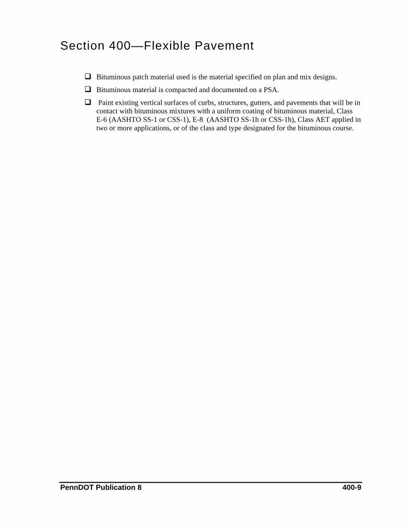
Section 400—Flexible Pavement
Bituminous patch material used is the material specified on plan and mix designs.
Bituminous material is compacted and documented on a PSA.
Paint existing vertical surfaces of curbs, structures, gutters, and pavements that will be in contact with bituminous mixtures with a uniform coating of bituminous material, Class E-6 (AASHTO SS-1 or CSS-1), E-8 (AASHTO SS-1h or CSS-1h), Class AET applied in two or more applications, or of the class and type designated for the bituminous course.
PennDOT Publication 8 400-9

Section 400—Flexible Pavement
2. Evaluation of Bituminous Pavement Ride Quality and Payment of Incentive This chapter addresses evaluating a bituminous pavement surface profile and determining the ride quality incentive associated with the surface profile.
References Publication 213 (Traffic Control)
Publication 408, Section 404 (Evaluation of Bituminous Pavement Ride Quality and Payment)
PTM 428 (Measuring Pavement Profile using a Light Weight Profiler)
Material & Equipment The contractor uses a lightweight profiler that has been verified by the department and which has a PennDOT certification sticker. The profiler must be an all terrain or golf cart type vehicle. In some instances, PennDOT may be running the profiler. Check the contract specifications for this case.
The profiler is calibrated each day for distance and profile; this activity should be witnessed.
Construction Methods Refer to PTM 428 for instructions on profiler operation.
The contractor must provide traffic control and sweep the pavement as necessary to accommodate testing.
The profiler is started 30 m (100 feet) before the area that is to be tested. The profiler makes a pass on the right wheel path and the left wheel path of each travel lane, traveling through the test area and 30 m (100 feet) beyond the test area. An average is calculated from the results of the two runs. Some profilers run both wheel paths at the same time.
Measuring & Payment Methods A full lot size is 161 meter (528 foot) of a single pavement lane, which is noted in Publication 408, Section 404. After the contractor runs the profiler, profile readings will be given to the inspector-in-charge. Payment is made according to Publication 408, Section 404.
Documentation On the PSA, document:
♦ Equipment type
♦ The PennDOT certification expiration date of the lightweight profiler
♦ That the operator is certified per PTM 428
♦ That the daily profiler calibration was for distance and profile was witnessed
PennDOT Publication 8 400-10
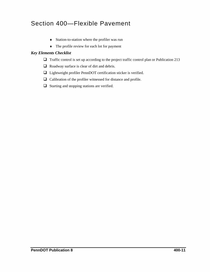
Section 400—Flexible Pavement
♦ Station-to-station where the profiler was run
♦ The profile review for each lot for payment
Key Elements Checklist Traffic control is set up according to the project traffic control plan or Publication 213
Roadway surface is clear of dirt and debris.
Lightweight profiler PennDOT certification sticker is verified.
Calibration of the profiler witnessed for distance and profile.
Starting and stopping stations are verified.
PennDOT Publication 8 400-11
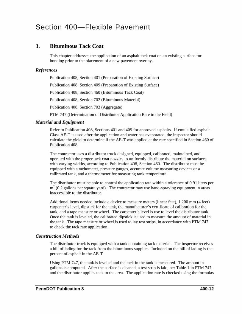
Section 400—Flexible Pavement
3. Bituminous Tack Coat This chapter addresses the application of an asphalt tack coat on an existing surface for bonding prior to the placement of a new pavement overlay.
References Publication 408, Section 401 (Preparation of Existing Surface)
Publication 408, Section 409 (Preparation of Existing Surface)
Publication 408, Section 460 (Bituminous Tack Coat)
Publication 408, Section 702 (Bituminous Material)
Publication 408, Section 703 (Aggregate)
PTM 747 (Determination of Distributor Application Rate in the Field)
Material and Equipment Refer to Publication 408, Sections 401 and 409 for approved asphalts. If emulsified asphalt Class AE-T is used after the application and water has evaporated, the inspector should calculate the yield to determine if the AE-T was applied at the rate specified in Section 460 of Publication 408.
The contractor uses a distributor truck designed, equipped, calibrated, maintained, and operated with the proper tack coat nozzles to uniformly distribute the material on surfaces with varying widths, according to Publication 408, Section 460. The distributor must be equipped with a tachometer, pressure gauges, accurate volume measuring devices or a calibrated tank, and a thermometer for measuring tank temperature.
The distributor must be able to control the application rate within a tolerance of 0.91 liters per m2 (0.2 gallons per square yard). The contractor may use hand-spraying equipment in areas inaccessible to the distributor.
Additional items needed include a device to measure meters (linear feet), 1,200 mm (4 feet) carpenter’s level, dipstick for the tank, the manufacturer’s certificate of calibration for the tank, and a tape measure or wheel. The carpenter’s level is use to level the distributor tank. Once the tank is leveled, the calibrated dipstick is used to measure the amount of material in the tank. The tape measure or wheel is used to lay test strips, in accordance with PTM 747, to check the tack rate application.
Construction Methods The distributor truck is equipped with a tank containing tack material. The inspector receives a bill of lading for the tack from the bituminous supplier. Included on the bill of lading is the percent of asphalt in the AE-T.
Using PTM 747, the tank is leveled and the tack in the tank is measured. The amount in gallons is computed. After the surface is cleaned, a test strip is laid, per Table 1 in PTM 747, and the distributor applies tack to the area. The application rate is checked using the formulas
PennDOT Publication 8 400-12
Section 400—Flexible Pavement noted in PTM 747. If the contractor uses an emulsified asphalt tack, the inspector should ensure that all of the water has evaporated before the bituminous pavement is placed.
Measuring & Payment Methods Tack coat may be paid by the square meter (square yard) or by the liter (gallon). The applications rate is checked according to PTM 747 and the area is field measured and computed to square yard and recorded on a PSA.
If paid by the liter (gallon), the distributor tank is measured per PTM 747 and the liter (gallon) applied are computed. The amount applied can also be determined by using the truck volume measuring device, but the device must be accurate.
Documentation On the PSA, document:
♦ Manpower and equipment used in the operation
♦ That the bill of lading was received from the bituminous material supplier
♦ That gauges on the distributor truck were checked and the temperature of the asphalt material in the tank was recorded
♦ The application rate of the tack and that it was checked per PTM 747
♦ Construction station where material was placed, which lane was paved, and the direction
♦ Calculations for payments for m2 (square yard) payment or liters (gallons), along with verification, via contractor ticket, of the number of liters (gallons) used
♦ Witness to tack coat application
Key Elements Checklist The distributor truck complies with Publication 408, Section 460.
The bituminous supplier has provided a bill of lading and the material is certified.
Material temperatures are within the limits shown on the bill of lading.
The surface is clean and dry.
Spray nozzles are clear and provide uniform spray.
The application rate is checked in the field, according to PTM 747.
All uncoated, lightly coated, or excessively coated areas are corrected.
Treated surfaces are protected against damage until succeeding construction.
A 1,200 mm (4 feet) level and a measuring device are used to compute the application rate.
If emulsified asphalt is used, all water has evaporated after its application and prior to paving.
PennDOT Publication 8 400-13
Section 400—Flexible Pavement
4. Bituminous Prime Coat This chapter addresses the conditioning and treating of an absorbent non-bituminous base course or existing absorbent surface with an application of bituminous material and, if required, a blotter material.
References Publication 213 (Traffic Control)
Publication 408, Section 461 (Bituminous Prime Coat)
Publication 408, Section 401 (Construction of Plant Mixed HMA Courses)
Publication 408, Section 460 (Bituminous Tack Coat)
Publication 408, Section 702 (Bituminous Material)
Publication 408, Section 703 (Aggregate)
PTM 747 (Determination of Distributor Application Rate in the Field)
Material & Equipment The material supplier will provide a bill of lading for the bituminous material, usually accompanying the first load of bituminous material.
The inspector should verify that the temperature of the bituminous material is within minimum and maximum heating temperatures shown on the bill of lading. The inspector should also verify that the material temperature is within minimum and maximum application temperatures as shown in Publication 408, Section 461.
The contractor uses a distributor designed, calibrated, equipped, and operated to uniformly apply material on surfaces with varying widths. The distributor should be equipped with a tachometer, pressure gauges, accurate volume measuring devices, or a calibrated tank. A thermometer for measuring the temperature of the material in the tank, a power operated pump, and spray bars with lateral and vertical adjustments should be available.
The contractor can use hand-spraying equipment in areas inaccessible to the distributor.
The inspector should use a device capable of measuring m (linear feet) for laying out a test strip in the field, per PTM 747, to check the application rate of the bituminous material. If the volume of material in the distributor tank is computed using the calibrated tank method per PTM 747, a 1,200 mm (4 feet) carpenter’s level is also required.
Construction Methods The surface receiving a prime coat is conditioned according to Publication 408, Sections 461 and 401. The bituminous material arrives at the project in a distributor truck. The contractor and the inspector check the temperature of the material in the distributor tank to ensure it is within minimum and maximum application temperatures shown in Publication 408, Section 461.
PennDOT Publication 8 400-14

Section 400—Flexible Pavement The distributor spray bars are set to the correct width and the contractor sprays the area to receive the prime coat. Areas that are uncoated or lightly coated should be re-sprayed.
Twenty-four hours after applying the prime coat, excess material is blotted with a fine aggregate, per Publication 408, Section 461. The treated surface must be maintained and protected against damage until adequately stable.
Measuring & Payment Methods This item is paid in square meter (square yard). Treated areas are field measured, computed to square meter (square yard), and computations recorded on a PSA. Progress payments can be made using construction station lengths, with the final adjusted payment based on final field measurements. All computations and payments are documented on a PSA.
Documentation On the PSA, document:
♦ That the base was conditioned per Publication 408, Sections 461 and 401
♦ That a bill of lading was obtained from the bituminous supplier, showing the minimum and maximum heating temperatures of the bituminous material
♦ Manpower and equipment used in the operation
♦ The temperature of the bituminous material in the distributor tank and that the temperature was within the specifications shown in Publication 408, Section 461
♦ Station-to-station where the bituminous material was placed
♦ The application rate of bituminous material using the procedures shown in PTM 747 and that the rate was within the specifications of Publication 408, Section 461
♦ Payment computations
Key Elements Checklist Traffic control is set up according to the traffic control plan or Publication 213.
The base is conditioned per Publication 408, Sections 461 and 401.
A copy of the bill of lading for the bituminous material is obtained from the supplier before the material is applied.
The distributor truck is equipped with all gauges required per Publication 408, Section 460 and calibrated.
The application rate of bituminous material is verified using the procedures shown in PTM 747 and the temperature of the bituminous material in the distributor tank is within specifications shown in Publication 408, Section 461.
Material certifications are obtained.
The treated area is protected and maintained until succeeding construction.
PennDOT Publication 8 400-15
Section 400—Flexible Pavement
5. Heavy-Duty Membranes This chapter addresses the placement of heavy-duty membranes over transverse joints, longitudinal joints, and random cracks in existing concrete pavements.
References Publication 213 (Traffic Control)
Publication 408, Section 467 (Heavy Duty Membranes)
Publication 408, Section 702 (Bituminous Material)
Bulletin 15 (Approved Construction Materials)
Manufacturer’s Installation Recommendations
Material & Equipment The heavy-duty membrane must come from an approved supplier as listed in Bulletin 15. The inspector should verify that there are no tears in the membrane material and take a linear measurement of the applied membrane.
The use of primers and binders may be required. These materials must be applied according to the manufacturer’s recommendations. Asphalt cement (Class PG 64-12 or PG 58-28) must meet the requirements of Publication 408, Sections 467 and 702. The contractor must receive approval for the supply source prior to starting work.
The contractor uses an air compressor to remove dirt and debris in joints and cracks. If cracks or joints are more than 6 mm (1/4 inch) wide, the contractor fills the joints or cracks with PG 64-22 or PG 58-28 using a tar buggy to heat and apply the asphalt.
Construction Methods The contractor removes all the dirt and debris from the joints and cracks. If the joints and cracks are more than 6 mm (1/4 inch) wide, they must be filled with asphalt per Publication 408, Section 467.
The surface is prepared according to the membrane manufacturer’s recommendations. If required, a manufacturer-recommended primer or binder is applied. The membrane is centered over the crack or joint and placed following the manufacturer’s instructions, incorporating all temperature and equipment requirements. All edges are securely bonded as indicated in Publication 408, Section 467.
Measuring & Payment Methods Heavy-duty membrane placement is paid in square meter (square yard). Application areas are field measured and square meter (square yard) are computed, with computations and payments documented in a PSA. Progress payment can be made using construction station lengths and plan widths. The final adjusted payment is based on field measurements.
PennDOT Publication 8 400-16

Section 400—Flexible Pavement
Documentation On the PSA, document:
♦ That a copy of the approved source of supply was obtained
♦ That surface cracks and joints were clean and dry and the surface prepared according to the manufacturer’s recommendations
♦ That any required asphalt is in accordance with Publication 408, Section 467 and was heated to the specifications set forth in Publication 408, Sections 401 and 409
♦ Station-to-station, lane, and direction of the application
♦ Manpower and equipment used in the operation
♦ Measurements and computations for payments
Key Elements Checklist An approved copy of the material source of supply is obtained.
Joints and cracks are clean and dry.
The surface receiving the membrane is prepared according to the manufacturer’s recommendations and Publication 408, Section 467.
Joint or cracks more than 6 mm (1/4 inch) in width are filled with asphalt material specified in Publication 408, Section 467.
The asphalt is heated to the temperatures specified in Publication 408, Sections 401 and 409.
Primers or binders, if required, are applied according to the manufacturer’s recommendations.
Membrane is placed in approximately the center of the crack or joint.
Traffic flow is reestablished according to the manufacturer’s recommendations and in accordance with the specifications in Publication 408.
A copy of the materials certification is received along with the manufacturers recommendations.
Strips with loose edges are rebonded or replaced prior to placing pavement
PennDOT Publication 8 400-17
Section 400—Flexible Pavement
6. Asphalt Joint and Crack Sealing This chapter addresses the cleaning and sealing of longitudinal and transverse joints, as well as cleaning and sealing cracks in existing pavement surfaces. The work is part of the routine maintenance required prior to placing an overlay.
References Publication 213 (Traffic Control)
Publication 408, Section 469 (Asphalt Joint and Crack Sealing)
Publication 408, Section 705 (Joint Material)
Material & Equipment The material required for this work is shown in Publication 408, Section 469. The material supplier will provide a bill of lading for the bituminous material if a bituminous wearing course FJ-1 is required. Obtain material from a source listed in Bulletin 15 or Bulletin 41, as applicable.
The contractor uses an air compressor to blow out joints and cracks, as outlined in Publication 408, Section 469. A tar buggy is used to heat the sealing material to temperatures recommended by the manufacturer.
Construction Methods The joints or cracks are cleaned and dried by air or routing. Pavement located 100 mm to 150 mm (4 inches to 6 inches) on either side of the joint or crack is cleaned. Joints or cracks 6 mm to 25 mm (1/
4 inch to 1 inch) wide are sealed with asphalt sealant. Larger cracks or joints (those larger than 25 mm [1 inch] wide) are sealed with an FJ-1 wearing course.
Measuring & Payment Methods Asphalt joint and crack sealing is paid by the meter (linear foot). Sealed joints and cracks are field measured. Joints or cracks or joints sealed with FJ-1 wearing course are paid by the tonne (ton), based on the weight recorded on the delivery tickets and the tonne (ton) incorporated in to the work.
Documentation On the PSA, document:
♦ That traffic control was set up according to a project traffic control plan or Publication 213
♦ That joints and cracks were prepared per Publication 408, Section 469
♦ That the sealing material used was an approved material as listed in Publication 408, Section 469 and was heated to the manufacturer’s recommended pouring temperature
♦ That the joints were sealed per Publication 408, Section 469
♦ Station-to-station where joints or cracks were sealed PennDOT Publication 8 400-18

Section 400—Flexible Pavement
♦ Manpower and equipment used in the operation
♦ The total meters (linear feet) of cracks or joints that the contractor sealed
Key Elements Checklist Traffic control is set up according to the project traffic control plan or Publication 213.
Joints or cracks are clean and dry and prepared according to Publication 408, Section 469.
Compressed air stream pressure should be as specified in Publication 408, Section 469.
Material shown in Publication 408, Section 469 is used and heated according to the manufacturer’s recommended pouring temperature.
Width of the joints and cracks is measured. Joints or cracks wider than 25 mm (1 inch) are sealed with an FJ-1 wearing course per Publication 408, Section 469. Joints or cracks 6 mm to 25 mm (1/4 inch to 1inch) wide are sealed with asphalt sealant.
Filled cracks and joints are level with the pavement surface.
Material certifications are obtained.
Placement occurs only when air temperatures are within a specified range.
PennDOT Publication 8 400-19

Section 400—Flexible Pavement
7. Bituminous Seal Coat & Bituminous Seal Coat Using Precoated Aggregate; Bituminous Surface Treatment & Bituminous Surface Treatment Using Pre-Coated Aggregate This chapter addresses the application of bituminous material, immediately followed by an application of a coarse aggregate or bituminous coated coarse aggregate. If only one layer of bituminous material and aggregate is placed, the work is considered Bituminous Seal Coat. If two layers of bituminous material and aggregate are placed, the work is considered Bituminous Surface Treatment.
References Publication 408, Section 108 (Character of Workers, Methods and Equipment)
Publication 408, Section 460 (Bituminous Tack Coat)
Publication 408, Section 469 (Asphalt Joint and Crack Sealing)
Publication 408, Section 470 (Bituminous Seal Coat)
Publication 408, Section 702 (Bituminous Material)
Publication 408, Section 703 (Aggregate)
PTM 747 (Determination of Distributor Application Rate in the Field)
Publication 25 (Bulletin 15), Approved Construction Materials
Publication 213 (Traffic Control)
Material & Equipment The bituminous material is job-specific and listed in Publication 408, Section 470. The coarse aggregate must also meet the requirements of Publication 408, Section 470. The bituminous material and coarse aggregate is normally stored at a bituminous batch plant.
The contractor uses a distributor designed, equipped, calibrated, maintained, and operated to uniformly apply material on surfaces with varying widths. The distributor must be equipped with a tachometer, pressure gauges, accurate volume measuring device or a calibrated tank, a thermometer to measure the temperature of tank contents, a power operated pump, full circulation spray bars, and all other requirements of Publication 408, Section 460.
To spread the coarse aggregate, the contractor uses a mechanical spreader capable of spreading 8.1 kg/m2 to 13.6 kg/m2 (15 to 25 lbs/square yards) and that meets all other requirements of Publication 408, Section 470. To roll the aggregate, the contractor must use a pneumatic tire roller meeting the requirements of Publication 408, Section 108.
The inspector needs a device capable of measuring meters (feet), such as a tape measure or a calibrated measuring wheel, to lay out a test strip (per PTM 747) to verify the application rate of the bituminous material.
Traffic is not permitted on the newly completed surface until the roadway material obtains adequate stability.
PennDOT Publication 8 400-20

Section 400—Flexible Pavement
Construction Methods Two weeks prior to the start of work, the contractor must submit a seal coat design for approval by the department. The area to receive the seal coat must be cleaned and cracks sealed according to Publication 408, Sections 469 and 470.
The contractor uses a distributor to apply the bituminous material at a rate within plus or minus 10% of the design rate. Immediately after applying the bituminous material, the contractor spreads a single layer of coarse aggregate with a mechanical spreader. The spreader is calibrated using a method acceptable to the inspector-in-charge (as outlined in Publication 408, Section 470) before the layer of coarse aggregate is applied. The aggregate is rolled with a pneumatic tire roller that meets the requirements of Publication 408, Section 108. Traffic is not permitted on the newly completed surface until the roadway material obtains adequate stability.
For Bituminous Surface Treatment, the second application of bituminous material is applied following the requirements of Publication 408, Section 480. Immediately after, the second application of coarse aggregate is placed, again in accordance with Publication 408, Section 480. To roll the aggregate, the contractor uses a pneumatic tire roller. If back rolling is required, the contractor may use a pneumatic tire roller or a steel wheel tandem roller. All rollers must all meet the requirements of Publication 408, Section 108.
Measuring & Payment Methods This item of work is normally paid in square meter (square yard). The area where the seal coat was applied is field measured, with computations documented on a PSA. Progress payments can be made using construction station lengths and plan widths, with final adjusted payment based on actual field measurements. All computations and payments are shown on a PSA. The width measured in the field should not exceed the plan width unless authorized by a department representative.
Documentation 1. Obtain a copy of the contractor’s approved seal coat design.
2. On the PSA, document:
♦ That traffic control was set up according to the project traffic control plan or Publication 213
♦ That the materials used are the same as those listed on the seal coat design and that the materials meet the requirements of Publication 408, Section 470
♦ That the air temperature, surface temperature, and condition of the area sealed are within specifications listed in Publication 408, Section 470
♦ Affirmation of the application rate per PTM 747
♦ Verification that the mechanical spreader was calibrated by an acceptable procedure
♦ Station-to-station, which lane, and what direction material was placed
PennDOT Publication 8 400-21
Section 400—Flexible Pavement
♦ Manpower and equipment used in the operation
♦ That the coarse aggregate material was rolled with a pneumatic tire roller meeting the requirements of Publication 408, Section 108. If back rolled, document which surface was back rolled and the type of roller used
♦ That the newly completed surface was not opened to traffic until the material obtained adequate stability
♦ That material certification is received for asphalt placed.
Key Elements Checklist Traffic control is set up according to the project traffic control plan or Publication 213.
Surfaces to be sealed are prepared per Publication 408, Section 469 and 470.
Weather conditions are within specifications listed in Publication 408, Section 470.
The calibrations of the distributor and mechanical spreader are verified.
Bituminous material is heated per the specification in Publication 408, Section 470.
Application rate is in accordance to PTM 747.
Aggregates are dry and from the same source of supply listed on the seal coat design.
A bill of lading is obtained for bituminous material from the bituminous supplier for each shipment of material.
Material certifications are obtained.
Material is not applied between the dates shown in Publication 408, Section 470.
Material has obtained adequate stability before opening to traffic.
PennDOT Publication 8 400-22
Section 400—Flexible Pavement
8. Slurry Seal This chapter addresses the construction of a bituminous slurry seal course. Type I is used to seal cracks, fill voids, and correct surface erosion. Type II is used to fill surface voids, correct severe surface erosion, and provide minimum wearing surface. Type III is used to provide a new moderate wearing surface or to build up a crown.
References: Publication 213 (Traffic Control)
Publication 408, Section 482 (Slurry Seal)
Publication 408, Section 702 (Bituminous Material)
Publication 408, Section 703 (Aggregates)
Publication 408, Section 720 (Water)
Material & Equipment The bituminous material and aggregate used for this work is listed in Publication 408, Section 482. The bituminous material and course aggregate for this operation are usually stored at a bituminous batch plant.
The contractor must use a self-propelled, continuous flow mixing apparatus capable of accurately proportioning, combining, and mixing the materials into a homogenous blend with an asphalt film of sufficient thickness to furnish the desired binding properties. The apparatus must incorporate bins, tanks, and receptacles of sufficient size, a measuring device for meters (feet), a mechanical mixer, and a distributor for placing the finished mixtures, as required by Publication 408, Section 482.
The contractor also needs a mechanically-operated squeegee-type distributor meeting the requirements of Publication 408, Section 482, as well as auxiliary equipment, such as hand squeegees, shovels, surface cleaning machines, and other hand equipment necessary to perform the work according to Publication 408, Section 482.
The inspector needs a thermometer to check slurry seal temperatures. The temperature of the slurry is checked in the distributor prior to application to ensure it is within the application temperature specified in the bill of lading, as outlined in Publication 408, Section 702.
Construction Methods The contractor must submit a slurry seal mix design and a quality control plan for approval prior to the start of work.
The contractor prepares the existing surface per Publication 408, Section 482. Depending on the requirements of the job, the contractor places Type I, Type II, or Type III slurry seals. Slurry is placed using the equipment shown in Publication 408, Section 482.
Traffic is prohibited from the surface until the slurry seal has completely cured.
PennDOT Publication 8 400-23

Section 400—Flexible Pavement
Measuring & Payment Methods Slurry seal is paid in square meter (square yard) based on actual field measurements and computations. Progress payments can be made using station-to-station construction lengths and plan widths. The final adjusted payment is based on actual field measurements. The width measured in the field for payment should not exceed plan width unless authorized by a department representative.
Documentation 1. On the PSA, document:
♦ That traffic control is set up per a traffic control plan and Publication 213
♦ That conditioning of the existing surface is performed per Publication 408, Section 482
♦ Manpower and equipment used in the operation
♦ The type of slurry seal used per Publication 408, Section 482
♦ That the equipment used to mix and place the slurry seal meets the requirements of Publication 408, Section 482
♦ Station-to-station construction lengths, land, and direction of the work performed
♦ That the temperature of the slurry seal components is within the range designated by the minimum and maximum application temperatures shown on the bill of lading
♦ Field measurements and computations
2. Obtain a copy of the contractor’s approved slurry seal mix design and a copy of the bill of lading for the bituminous materials from the bituminous supplier, showing material minimum and maximum heating temperatures.
Key Elements Checklist A copy of the approved slurry seal mix design and approved quality control plan is
obtained.
A copy of the bill of lading for the bituminous material is obtained.
Traffic control is set up per the project traffic control plan or Publication 213, if required
Existing surface is conditioned per Publication, 408 Section 482.
Material temperatures are within the application range shown in Publication 408, Section 482 and the bill of lading.
Equipment meets the requirements of Publication 408, Section 482.
PennDOT Publication 8 400-24
Section 400—Flexible Pavement
9. Removal of Existing Surface Course This chapter addresses the removal of an existing surface course.
References Publication 213 (Traffic Control)
Publication 408, Section 490 (Removal of Existing Surface Course)
Material & Equipment Most commonly, the contractor uses a milling machine to remove an existing surface course. Another method the contractor may use is to saw cut the limits of pavement removal and use excavating equipment, such as a front loader or gradeall, to remove the surface course.
Construction Methods The contractor must submit and receive approval for the removal procedure. The project special provisions may specify requirements for the operation, while areas of removal may be shown on the project plan or be directed by a department representative.
Material removed is hauled to an approved waste area or a department-designated area. If, during the removal, the existing base or adjacent pavement surface is damaged, the contractor must repair the damage.
Measuring & Payment Methods Removal of an existing surface course is paid in square meter (square yard) using actual field measurements, with computations shown on a PSA. Progress payments can be made using station-to-station lengths and plan widths. The final adjusted payment is based on actual field measurements.
Documentation On the PSA, document:
♦ That traffic control is set up per a traffic control plan or Publication 213
♦ Manpower and equipment used in the operation
♦ That the contractor used an approved method to remove existing pavement
♦ Station-to-station, lane, and direction of the work performed
♦ That the edges of the remaining bituminous surface were trimmed to a neat vertical line
♦ That the excavated material was hauled to an approved waste area
PennDOT Publication 8 400-25

Section 400—Flexible Pavement
Key Elements Checklist Traffic control is set up per a project traffic control plan or Publication 213.
The contractor’s removal method is approved.
Any damage to the base course and adjacent surface is repaired by the contractor.
PennDOT Publication 8 400-26
Section 400—Flexible Pavement
10. Milling of Bituminous Pavement Surface, Profile Milling, Variable Depth This chapter addresses the milling of an existing bituminous pavement surface, variable depth and profile milling.
References Publication 408, Section 491 (Milling of Bituminous Pavement Surface)
Publication 408, Section 492 (Profile Milling of Bituminous Pavement Surface)
Publication 213 (Traffic Control)
Material & Equipment The contractor needs a milling machine designed and built for milling existing bituminous pavements. The machine should have an automatic grade and slope control system, be capable of milling concrete patches, and meet all of the requirements of Publication 408, Sections 491 or 492, whichever applies. The contractor may also need a survey instrument to establish finish grades.
Hauling equipment, including dump trucks or front loaders, is used to remove milled material from the work area. The contractor uses a power broom to sweep the milled surface after the milling operation is complete.
The inspector needs a 1,200 mm (4 feet) level to check the cross slope of the milled pavement to ensure it meets plan requirements and a device, such as a tape measure or engineer’s rule, to measure the depth of the milled area. A survey instrument may be required for the contractor to establish finish grades for the milling operation.
Construction Methods Variable depth milling involves milling existing bituminous pavement down to an existing concrete pavement or base course. Profile milling involves milling of an existing pavement to establish a uniform profile and cross slope.
On both profile and variable depth milling operations, the contractor establishes milling control grades and marks these on the pavement or on offset stakes.
The contractor uses a milling machine with automatic grade and slope controls to mill the pavement surface as required by plan
Measuring & Payment Methods Milling is paid in square meter (square yard). The areas are field measured and computed on a PSA for payment. Progress payments can be made based on construction station lengths and plan widths, with the final adjusted payment based on actual field measurements. All computations and payments are documented on a PSA.
PennDOT Publication 8 400-27

Section 400—Flexible Pavement
Documentation On the PSA, document:
♦ That traffic control was set up per a traffic control plan or Publication 213
♦ Manpower and equipment used in the operation
♦ Whether variable depth or profile milling is being performed
♦ Station-to-station length, what lane, and where the work was performed
♦ That the milling equipment used by the contractor produces a surface tolerance that meets the requirements of Publication 408, Section 401
♦ That the inspector checked the cross slope of the milled surface and it met plan requirements
♦ That the rate of milling does not tear the mat
♦ That the milled pavement surface is maintained free of loose material and dust
♦ That the milled material was taken to an approved waste area or a department designated site
Key Elements Checklist Traffic control is set up per the project traffic control plan or Publication 213.
The milling machine is capable of milling the existing pavement to plan profile and cross slope. The milling machine is equipped with automatic grade and slope controls.
The contractor has established and laid out the proper grade and cross slope.
The rate of milling does not tear the mat.
Milling does not damage utility covers. If damage occurs to any utility covers, the contractor replaces them.
The finished surface should be free of gouges, grooves, and ridges and meet the requirements of Publication 408, Section 401 and plan requirements.
Milled material is hauled to an approved waste area and the hauling is documented on a PSA.
PennDOT Publication 8 400-28

Section 400—Flexible Pavement
11. Preparation of Bases This chapter addresses the preparation of a base course before a binder course is placed.
References Publication 213 (Traffic Control)
Publication 408, Section 401 (Conventional Mixture Design, Standard and RPS Construction of Plant Mixed HMA Courses)
Publication 408, Section 409 (Superpave Mixture Design, Standard and RPS Construction of Plant Mixed HMA Courses)
Publication 408, Section 460 (Bituminous Tack Coat)
PTM 747 (Determination of Distributor Application Rate in the Field)
Material & Equipment A bituminous material meeting the requirements of Publication 408, Sections 401 and 409 may be applied to the existing vertical surfaces of curbs, structures, gutters, and pavements. A tack coat meeting the requirements of Publication 408, Section 460 is applied to existing surfaces before overlaying.
The contractor needs a power broom to sweep the base course, if necessary, before application of the tack coat, if required. The contractor needs a distributor designed, equipped, calibrated, maintained, and operated to uniformly apply material on surfaces with varying widths up to 4.6 m (15 feet). The distributor must also be equipped with a tachometer, pressure gauges, accurate volume measuring devices or a calibrated tank, a thermometer for measuring the temperatures of tank contents, a power operated pump, and full circulation spray bars with lateral and vertical adjustments. The distributor must meet all requirements of Publication 408, Section 460.
The inspector needs a 1,200 mm (4 feet) level to check the cross slope of the existing base to ensure it meets plan requirements. The inspector also needs a 3,000 mm (10 feet) straightedge to check the existing base surface for irregularities that may require correction before overlay placement.
Construction Methods The contractor must condition the existing base per the requirements of Publication 408, Sections 401 and 409.
The contractor applies a tack coat meeting the requirements of Publication 408, Sections 401 and 409. The tack coat is applied with a distributor meeting the requirements of Publication 408, Section 460
Measuring & Payment Methods If required, the cleaning and sealing of existing joints and cracks is paid by the meter (linear foot), using field measurements and paid on a PSA. If a scratch leveling course is required, it
PennDOT Publication 8 400-29
Section 400—Flexible Pavement is paid by the tonne (ton) of material incorporated into the work, as shown on the delivery tickets.
The tack coat is paid in square meter (square yard). The areas of application are field measured, computed, and paid on a PSA. Progress payments can be made on square meter (square yard) items, using construction station lengths and plan widths. The final adjusted payment is based on actual field measurements.
Documentation On the PSA, document:
♦ That traffic control was set up per the project traffic control plan or Publication 213
♦ That the existing base was conditioned per the requirements of Publication 408, Sections 401 and 409
♦ The individual who approved the base for overlaying
♦ That an approved tack coat was applied and the application rate was applied per PTM 747
♦ Computations for the application rate
Key Elements Checklist Traffic control is set up per the project traffic control plan or Publication 213.
The base must be checked and approved by the inspector-in-charge before the overlaying operation begins.
The base course is inspected for cracks, faulty joints, and faulty drainage, and required patching is completed. If the base is rutted or has depressions of 25 mm (1 inch) or greater, a scratch course of binder or wearing may be required before the binder course is placed.
All unsuitable material, patches, and excess crack or joint sealer is removed.
All joints are cleaned and resealed.
Tack coat application per PTM 747 and as per Publication 408, Section 460.
Material certifications are obtained.
A bill of lading for the bituminous material used for tack is received from the bituminous supplier.
PennDOT Publication 8 400-30
Section 400—Flexible Pavement
12. Operation of Paver This chapter addresses the operation of a bituminous paver.
References Publication 408, Section 401 (Conventional Mixture Design, Standard and RPS Construction of Plant Mixed HMA Courses)
Publication 408, Section 409 (Superpave Mixture Design, Standard and RPS Construction of Plant Mixed HMA Courses)
Material & Equipment Pavers should be self-contained and power propelled, with activated screeds and automatic screed controls capable of producing a finished surface of specified evenness and texture. The paver must meet all the requirements of Publication 408, Sections 401 and 409.
The paver must be set at the required depth and cross slope at the beginning of the paving operation. Prior to compaction, the inspector should check the mat behind the paver for uniformity. If the mat is not uniform, the inspector should check the screed and make sure the screed is hot. Slow, continuous movement of the paver provides for a uniform ride surface. However, any adjustments to the paver are made by the contractor.
Documentation On the PSA, document:
♦ The type and size of the paver and that it meets all the requirements of Publication 408, Sections 401 and 409
♦ That the automatic screed was activated and the screed was kept hot during the paving operation
♦ That the cross slope and mat thickness was verified at the beginning of paving and checked randomly throughout the paving operation
Key Elements Checklist The paver has activated screeds with automatic screed controls and meets all of the
requirements in Publication 408, Sections 401 and 409.
The texture of the mat behind the paver is uniform.
After the first truckload is placed, depth and cross slope are verified. The mass per m2 (weight per square yard) is computed to determine yield.
The paver carries no oils, solvents, or debris that would damage the pavement.
PennDOT Publication 8 400-31

Section 400—Flexible Pavement
A. Checking Thickness of Mat This subchapter addresses the measurement of bituminous pavement before and after compaction.
References Publication 408, Section 401 (Conventional Mixture Design, Standard and RPS Construction of Plant Mixed HMA Courses)
Publication 408, Section 409 (Superpave Mixture Design, Standard and RPS Construction of Plant Mixed HMA Courses) PTM 737 (Measuring the Thickness of Bituminous Concrete Course)
Approved Quality Control Plan
Material & Equipment The contractor needs a bituminous concrete coring machine capable of drilling 150 mm (6 inches) cores through the pavement.
In addition, the contractor and the inspector need a metal measuring device that is capable of being inserted through the pavement mat, before and after compaction, to verify the depth of the mat.
Construction Methods The contractor, using a measuring device inserted through the mat behind the paver, takes depth checks of the mat before and after compaction.
For courses with density acceptance, cores are taken by the contractor in accordance with the approved quality control plan and are measured by the inspector according to PTM 737. For courses with acceptance by visual non-movement under compaction equipment for density, the inspector calculates the mass per m2 (weight per square yard) for verification of yield. The yield should be checked randomly throughout the paving operation.
Measuring & Payment Methods There are no measuring and payment methods associated with this item.
Documentation On the PSA, document:
♦ That depth checks were taken by the inspector and the contractor in the loose and compacted mat
♦ That core locations were calculated per Publication 408, Sections 401 and 409
PennDOT Publication 8 400-32

Section 400—Flexible Pavement
♦ That the inspector witnessed the contractor removing pavement cores and that the cores were measured by the inspector, using procedures shown in PTM 737 (The core measurements are documented on a PSA or in a Field Survey Book.)
♦ That the yield of material placed was calculated in mass per m2 (weight per square yard)
Key Elements Checklist A measuring device capable of being inserted through pavement mat is obtained.
Depth checks taken by the contractor are witnessed.
Core locations are identified and core taking is witnessed.
Cores are measured using procedures outlined in PTM 737 and the results documented on a PSA.
Mass per m2 (weight per square yard) is calculated to verify the yield.
PennDOT Publication 8 400-33
Section 400—Flexible Pavement
13. Hand Spreading and Finishing This chapter addresses the spreading and finishing of bituminous material with hand tools.
References Publication 408, Section 401 (Conventional Mixture Design, Standard and RPS Construction of Plant Mixed HMA Courses)
Publication 408, Section 409 (Superpave Mixture Design, Standard and RPS Construction of Plant Mixed HMA Courses)
Material & Equipment The contractor uses a variety of hand tools, including lutes, shovels, a straight edge, and a level, for hand spreading and finishing. Lutes and shovels are used in placing and striking off newly-placed material, while a 3,000 mm (10 feet) straightedge and 1,200 mm (4 feet) level are used to check the pavement cross slope and profile. In addition, the contractor needs a vibratory plate and hand tamper to compact the material.
The inspector also need a 1,200 mm (4 feet) level to check the cross slope of the pavement, as well as a 3,000 mm (10 feet) straight edge to check the new pavement profile.
Construction Methods In spreading and finishing bituminous pavements, hand tools are only to be used in areas where mechanical spreading cannot be performed.
The contractor places the material by end dumping it into position or by using equipment such as a front end loader. The material is then shoveled and hand-luted into position.
Before rolling, the material is checked with a 3,000 mm (10 feet) straight edge and a 1,200 mm (4 feet) level for profile and cross slope. When the material is spread by hand, a greater allowance is made for the reduction of thickness during compaction. After the material is placed and checked, the contractor compacts the material with a vibratory plate or a hand tamper.
Measuring & Payment Methods This work is incidental to the material placed.
Documentation On the PSA, document:
♦ Manpower and equipment used in the operation
♦ That the material was placed by hand because the area was not accessible to paving equipment
♦ That the cross slope was verified before compaction and that depth checks were verified for the material being placed
PennDOT Publication 8 400-34
Section 400—Flexible Pavement
♦ That the contractor verified the cross slope and profile of the new surface with a 3,000 mm (10 feet) straightedge
♦ Station-to-station, lane, direction, and where the work was performed
♦ How the material was compacted
Key Elements Checklist Hand tools used meet the requirements of Publication 408, Sections 401 and 409. Rakes
are not permitted.
Neither oils nor solvents are used to clean tools (to protect the pavement mat).
Material temperature is verified prior to placement.
Prior to compacting, a straight edge and level are used to verify surface profile and cross slope.
Prior to compaction, depth checks are taken and the results recorded.
Material certifications are obtained.
PennDOT Publication 8 400-35
Section 400—Flexible Pavement
14. Compacting Binder and Wearing Courses This chapter addresses is the compaction of a binder and wearing course.
References Publication 408, Section 401 (Conventional Mixture Design, Standard and RPS Construction of Plant Mixed HMA Courses)
Publication 408, Section 409 (Superpave Mixture Design, Standard and RPS Construction of Plant Mixed HMA Courses)
PTM 402 (Determining the Density of In-Place Construction Material Using a Nuclear Gauge)
PTM 403 (Determining In-Place Density of Bituminous Concrete Using Electrical Impedance Measurement Methods)
Approved Quality Control Plan
Material & Equipment The contractor must supply rollers meeting the requirements of Publication 408, Section 108. The number, size, and number of roller passes is determined by the contractor’s technician, who uses a nuclear gauge to set up a rolling pattern per PTM 402 or PTM 403. The contractor is required to supply the nuclear gauge or electrical impedance gauge as well as a certified operator.
The inspector needs a thermometer capable of measuring the surface temperature of the newly-placed material.
Construction Methods After the pavement is placed, the rolling operation begins directly behind the paver. The contractor’s technician, using a nuclear gaug or electrical impedance gauge and information from the quality control paving plan, establishes a rolling pattern following the procedures outlined in PTM 402 or PTM 403. This procedure ensures that the required density is achieved. The number, type, and number of roller passes are established by the rolling pattern.
The joint is pinched with a roller, which is placed approximately 100 mm (4 inches) onto the uncompacted material from the existing pavement and operates parallel to the transverse joint. The initial roll across the joint parallel to the pavement centerline should be done slowly with a tandem roller, with a first pass of 900 to 1,200 mm (3 to 4 feet). Roller pass overlays should be one-half the width of the roller.
Traffic is not permitted on the pavement until the surface temperature is below 60 °C (140F).
Measuring & Payment Methods This work is incidental to the type of material placed
PennDOT Publication 8 400-36

Section 400—Flexible Pavement
Documentation On the PSA, document:
♦ That the contractor’s technician established a rolling pattern with a nuclear gauge, using the procedures outlined in PTM 402
♦ That the material was rolled using the established rolling pattern
Key Elements Checklist Using a nuclear gauge, a rolling pattern is established by the contractor’s technician to
determine the number of rollers, number of roller passes, and types of rollers.
The breakdown roller stays close to the paver. Rubber tired rollers are usually used for scratch leveling courses.
The rollers meet the requirements of Publication 408, Section 108.
PennDOT Publication 8 400-37

Section 400—Flexible Pavement
15. Constructing Longitudinal Joints This chapter addresses the construction of longitudinal joints in bituminous paving.
References Publication 408, Section 108 (Character of Workers; Methods and Equipment)
Publication 408, Section 401 (Conventional Mixture Design, Standard and RPS Construction of Plant Mixed HMA Courses)
Publication 408, Section 409 (Superpave Mixture Design, Standard and RPS Construction of Plant Mixed HMA Courses)
RC Standard 28M (Overlay Transitions and Paving Notches)
Material & Equipment The contractor needs a bituminous paver and rollers meeting the requirements of Publication 408, Sections 401 and 409. The rollers must meet the requirements of Publication 408, Section 108.
A 3 m (10 feet) straight edge is used to verify that the joints are smooth and uniform.
Construction Methods Longitudinal joints are offset about 150 mm (6 inches) from the joint in the layer immediately below. Plan joint locations should be calculated to ensure that the joint in the top layer is at approximately pavement centerline.
Vertical joints may be used in base, binder, and wearing courses. The abutting lane is placed on the same day, if possible.
A notched wedge joint can be used on binder and wearing courses if the mix is 19 mm (3/4 inch) as shown in the RC standards. The abutting lane joint is painted with a thin coat of bituminous material as specified in Publication 408, Sections 401 and 409.
The joint is pinched with a roller. Pinching is accomplished by making a first roll on approximately 100 mm (4 inches) of the uncompacted pavement at the longitudinal joint adjacent to the existing or newly compacted pavement. (The roller straddles the uncompacted material and the pavement.)
Measuring & Payment Methods This work is incidental to the type of material placed
PennDOT Publication 8 400-38

Section 400—Flexible Pavement
Documentation On the PSA, document:
♦ That the joint was either a straight vertical joint or a notched wedge joint
♦ That a coat of bituminous material, meeting the requirements of Publication 408, Sections 401 and 409, was applied to the joint before the abutting lane was placed
♦ That the material was not overlapped at the joint and that the joint was compacted properly
♦ That the material was placed per all requirements of Publication 408, Sections 401 and 409
♦ That the contractor constructed the joints following the procedures of the approved quality control plan
Key Elements Checklist A copy of the contractor’s quality control plan is obtained.
A nearly vertical edge or a notched wedge exists per RC Standard 28-M.
Joints are offset 1,500 mm (6 inches) from the joint in the layer immediately below. The top joint is at approximate pavement centerline.
The joint is coated with an approved bituminous material before an abutting lane is placed.
The joint is rolled to ensure that it is closed and compacted.
The contractor follows the approved quality control plan.
PennDOT Publication 8 400-39
Section 400—Flexible Pavement
16. Constructing Transverse Joints This chapter addresses the construction of transverse joints in bituminous pavements.
References Publication 408, Section 401 (Conventional Mixture Design, Standard and RPS Construction of Plant Mixed HMA Courses)
Publication 408, Section 409 (Superpave Mixture Design, Standard and RPS Construction of Plant Mixed HMA Courses)
RC Standard 28M (Overlay Transitions and Paving Notches)
Material & Equipment The contractor needs a bituminous paver and hand tools meeting the requirements of Publication 408, Sections 401 and 409. Rollers must meet the requirements of Publication 408, Section 108.
The contractor also needs a 3 m (10 feet) straight edge to check joints transversely and longitudinally, ensuring that they are smooth and uniform.
Construction Methods A strip of roofing paper, burlap, or white plastic can be put down to make a joint at the end of the day’s paving (this is called a papered joint). Bituminous material is then placed on the strip. With this method, rollers coming off the pavement will not damage or round the joint.
Immediately prior to paving, the excess material and plastic can be removed, and a vertical joint with a tack coat meeting Publication 408 standards is constructed. When starting to pave at a transverse joint on an existing pavement, the contractor should place wooden blocks thick enough to allow for the compaction of the material on the existing pavement. The paver screed is then set down on the wooden blocks to start paving at the joint. As a rule of thumb, an asphalt material is expected to compact approximately 20% under compaction equipment. The thickness of the wooden blocks should be calculated using this 20% compaction rule.
The joint is pinched with a roller, which is placed approximately 100 mm (4 inches) onto the uncompacted material from the existing pavement and operating parallel to the transverse joint. The initial roll across the joint parallel to the pavement centerline should be done slowly with a tandem roller, with a first pass of 900 to 1,200 mm (3 to 4 feet). Roller pass overlays should be one-half the width of the roller.
Measuring & Payment Methods This work is incidental to the type of material placed.
PennDOT Publication 8 400-40
Section 400—Flexible Pavement
Documentation On the PSA, document:
♦ That the joint was vertical and perpendicular to pavement surface
♦ That a bituminous material was applied to the existing vertical edge (before an abutting lane was placed) that meets all the requirements of Publication 408, Sections 401 and 409
♦ That the rolling operation for the compaction of material at the joint was performed per Publication 408, Sections 401 and 409 and the contractor’s quality control plan
♦ That the joint was checked with a string line or straight edge to ensure it meets specifications outlined in Publication 408, Sections 401 and 409
Key Elements Checklist The joint is nearly vertical and the tack coat applied, meeting the requirements of
Publication 408, Sections 401 and 409.
Rollers meet the requirements of Publication 408, Section 108.
The joint is rolled per the contractor’s approved quality control plan.
The joint is checked with a string line or a straight edge before and after compaction of to ensure it meets specifications outlined in Publication 408, Sections 401 and 409.
PennDOT Publication 8 400-41
Section 400—Flexible Pavement
17. Testing HMA This chapter addresses tests for pavement density, pavement surfaces, and loose box samples.
References Publication 408, Section 401 (Conventional Mixture Design, Standard and RPS Construction of Plant Mixed HMA Courses)
Publication 408, Section 409 (Superpave Mixture Design, Standard and RPS Construction of Plant Mixed HMA Courses)
PTM 402 (Determining the Density of In-Place Construction Material Using a Nuclear Gauge)
PTM 403 (Determining In-Place Density of Bituminous Concrete Using Electrical Impedance Measurement Methods)
Material & Equipment The contractor is required to have a nuclear gauge meeting the requirements of Publication 408, Sections 401 and 409 to test for pavement density and to establish a rolling pattern (using procedures outlined in PTM 402). The contractor also needs a core machine to remove 150 mm (6 inches) diameter cores for density testing and depth checks.
The inspector needs a 3,000 mm (10 feet) straight edge to check the pavement profile for irregularities. Both the inspector and the contractor need a 1,200 mm (4 feet) level to check the cross slope of the newly-placed pavement.
The inspector needs a thermometer to check the temperature of the bituminous material to ensure it is within the specifications shown in Publication 408, Sections 401 and 409.
Construction Methods The contractor’s technician uses a nuclear gauge or an electrical impedance gauge to establish a rolling pattern (following the requirements of PTM 402 or PTM 403) to ensure that material is compacted to the required density.
The inspector selects the loose box and core samples according to PTM 1, PTM 729 and PTM 746 at the frequencies specified in Publication 408, Sections 401 and 409. Samples are identified by the inspector and collected by the contractor’s technician, with the inspector witnessing the collection of the samples. The samples are shipped by the inspector to the Materials Testing Division (MTD) for testing.
The surface of the pavement is checked with a 3,000 mm (10 feet) straight edge. The straight edge is placed on the pavement surface parallel to the roadway centerline and advanced in stages of not more than half the length of the straight edge. A string line can also be used to check pavement profile, using a 15 m (50 feet) string line and three wooden blocks of the same thickness. The string line is stretched across the top of two blocks placed 15 m (50 feet) apart, while the third block is slid under the string to check for irregularities.
PennDOT Publication 8 400-42
Section 400—Flexible Pavement
Measuring & Payment Methods This work is incidental to the type of material placed.
Documentation On the PSA, document:
♦ That bituminous material temperatures were taken and within the requirements outlined in Publication 408, Sections 401 and 409
♦ That the inspector identified core and loose box sample locations and witnessed the contractor taking them
♦ Computations for locations and stations of where loose box and core samples
♦ Station-to-station, lane, and direction of work and any defects
♦ That the contractor’s technician used a nuclear gage (following the guidelines of PTM 402) to establish a rolling pattern and that the activity was witnessed by an inspector
Key Elements Checklist The contractor’s technician used a nuclear gauge to check density and establish a rolling
pattern per PTM 402.
Material temperatures are verified at time of placement.
The pavement surface is verified with a straight edge per Publication 408, Section 401. The pavement is defective if irregularities are more than 5 mm (3/16 inch) in size.
The binder course is uniform and to grade and cross slope, ensuring a good ride quality on the wearing course surface.
Core locations for density are established per Publication 408, Sections 401 and 409.
Loose box samples for mixture acceptance are taken per Publication 408, Sections 401 and 409.
PennDOT Publication 8 400-43

Section 400—Flexible Pavement
18. Protection of Surface Courses This chapter addresses the protection of newly-placed surface courses.
References Publication 408, Section 401 (Conventional Mixture Design, Standard and RPS Construction of Plant Mixed HMA Courses)
Publication 408, Section 409 (Superpave Mixture Design, Standard and RPS Construction of Plant Mixed HMA Courses)
Publication 408, Section 105 (Control of Work)
Publication 408, Section 107 (Opening Sections of Project to Traffic)
Publication 408, Section 901 (Maintenance and Protection of Traffic During Construction)
Publication 213 (Traffic Control)
Material & Equipment The inspector and the contractor need a calibrated surface thermometer or infrared temperature gun to check the surface temperature of the newly-placed bituminous course.
Construction Methods The contractor sets up traffic control per the traffic control plan or Publication 213. After the paving operation is completed, vehicular traffic or hauling equipment is not permitted on newly-compacted courses for 24 hours or until the mixture uniformly cools to a temperature of 60 °C (140F) or lower. The contractor maintains the course as specified in Publication 408, Sections 105, 107, and 901.
Measuring & Payment Methods This work is incidental to the type of material placed.
Documentation On the PSA, document:
♦ That traffic control was set up per the traffic control plan or Publication 213
♦ That traffic was not permitted on the newly constructed pavement course until the surface temperature of the course was below 60 °C (140F)
Key Elements Checklist Surface temperature of the newly-placed bituminous course is checked with a calibrated
surface thermometer or infrared temperature gun.
Traffic is not permitted on the newly placed bituminous course until the surface temperature is below 60 °C (140F).
PennDOT Publication 8 400-44

Section 400—Flexible Pavement
19. Shoulder Construction This chapter addresses the construction of all types of bituminous shoulders.
References Publication 408, Section 651 (Paved Shoulders Type 1, 1-F, 1-I, 1-S, and 1-SP)
Publication 408, Section 653 (Paved Shoulders Type 3)
Publication 408, Section 654 (Paved Shoulders Type 4)
Publication 408, Section 656 (Paved Shoulders Type 6, 6-F, 6-I, 6-S, and 6-SP)
Publication 408, Section 657 (Paved Shoulders Type 7)
RC Standard 25M (Shoulders)
Publication 2, Project Office Manual, Part C, Section 4 (Flexible Pavements)
Approved Quality Control Plan
Approved Bituminous Mix Designs
Material & Equipment Required materials are shown on RC Standard 25M or in Publication 408 for the type of shoulder to be constructed. There may also be a typical drawing on the project plan showing the configuration of the shoulder and what types of materials are to be used.
A 1,200 mm (4 feet) shoulder is usually paved monolithic with the lane paving, depending on the type of shoulder under construction. A 1,200 mm (4 feet) extension on the paver screed should be used if possible. Sometimes, the shoulder is placed with a widener.
The right shoulder, also referred to as the 3,000 mm (10 feet) shoulder, is placed with a paver meeting the requirements of Publication 408, Sections 401 and 409. The width of the shoulder dictates the type of paving equipment required.
The contractor needs a distributor meeting the requirements of Publication 408, Section 460, as well as a mechanical aggregate spreader (for certain types of shoulders). Rolling equipment is determined by the type of shoulder to be constructed and the requirements of Publication 408, Section 108.
The inspector needs a 3,000 mm (10 feet) straightedge to check the shoulder profile and shoulder construction joints, per Publication 408, Sections 401 and 409, and a 1,200 mm (4 feet) level to check the cross slope to ensure it meets plan requirements. The inspector also needs a thermometer or infrared temperature gun capable of reading temperatures to 205 °C (400F) to check the temperature of the bituminous material before placement to ensure it is within specifications.
Construction Methods Construction methods vary depending on the type of shoulder constructed. Shoulders are constructed per plan drawings, and must meet the requirements of Publication 408 and RC
PennDOT Publication 8 400-45
Section 400—Flexible Pavement Standard 25M. Unless a shoulder is required to carry traffic to accommodate a future MPT stage, it would not be constructed using the same pavement structure as the adjacent lanes. Typically, the contractor constructs the lanes, then comes back and places additional subbase for the shoulder. Once the additional subbase has been fine graded and compacted, the shoulder is constructed using the pavement structure identified in the contract. Most shoulders consist of a base course and wearing course. Blacktop courses for shoulders are constructed using the same methods as for travel lanes. Shoulders 3 m (10 feet) and wider are usually constructed with a paver; shoulders less than 3 m (10 feet) wide are constructed using a widener.
Measuring & Payment Methods Depending on the contract documents, shoulders are usually paid by the square meter (square yard). The shoulders are field measured and computed, with computations and payments shown on a PSA. Progress payments can be made based on construction station lengths and plan widths. The final adjusted payment is based on actual field measurements. The measured width in the field for payment should not exceed plan width unless authorized by a department representative.
Documentation On the PSA, document:
♦ The type of shoulder being constructed and that the shoulder is constructed per Publication 408 specifications and RC Standard 25M for the type indicated
♦ Manpower and equipment used in the operation
♦ Station-to-station where work was performed
♦ All of the construction activities in preparing and placing the type of shoulders indicated on plan drawings, ensuring that the construction meets Publication 408 specifications and RC Standard 25M specifications
Key Elements Checklist Surface (subbase or existing pavement) preparation is approved before shoulders are
placed.
A copy of the contractors approved mix design and quality control plan is obtained and reviewed.
Tack coat is applied per specifications.
All material placed is within specifications.
Material is compacted per specifications.
Cross slope and depth of courses is verified and in accordance with pavement structure for type of shoulder.
PennDOT Publication 8 400-46

Section 500—Rigid Pavement
Table of Contents 1. Reinforced or Plain Cement Concrete Pavements, Reinforced or Plain Cement
Concrete Pavement (RPS), and Protective Coating for Cement Concrete Pavement............500-1 2. Pavement Relief Joint ............................................................................................................500-7 3. Bridge Approach Slabs ..........................................................................................................500-9 4. Evaluation of Concrete Pavement Ride Quality and Payment of Incentive ........................500-12 5. Longitudinal Grooving of Existing Concrete Pavement, Transverse Grooving of
Concrete pavements for Retexturing, and Diamond Grinding of Concrete Pavement........500-15 6. Pressure Relief Joint, Longitudinal Joint Cleaning and Sealing, Joint Rehabilitation,
Transverse Joint Cleaning and Sealing, and Crack Cleaning and Sealing ..........................500-18 7. Sawing and Sealing of Bituminous Overlays ......................................................................500-22 8. Concrete Pavement Patching and Continuously Reinforced Concrete Pavement
Patching ...............................................................................................................................500-24 9. Thin Bonded Portland Cement Concrete Overlay ...............................................................500-29 10. Concrete Pavement Spall Repair .........................................................................................500-32 11. Rubblizing of Concrete Pavements .....................................................................................500-35
PennDOT Publication 8 500-i

Section 500—Rigid Pavement
This Page Left Intentionally Blank
PennDOT Publication 8 500-ii
Section 500—Rigid Pavement
1. Reinforced or Plain Cement Concrete Pavements, Reinforced or Plain Cement Concrete Pavement (RPS), and Protective Coating for Cement Concrete Pavement This chapter addresses:
• Reinforced or plain cement concrete pavements
• Reinforced or plain cement concrete pavement restrictive performance standards (RPS)
• Protective coatings for cement concrete pavement
References Publication 408, Section 501 (Reinforced or Plain Cement Concrete Pavements)
Publication 408, Section 506 (Reinforced or Plain Cement Concrete Pavement RPS)
Publication 408, Section 503 (Protective Coating for Cement Concrete Pavement)
Publication 408, Section 704 (Cement Concrete)
RC Standard 21M (Reinforced Concrete Pavement)
RC Standard 27M (Plain Concrete Pavement)
Bulletin 15 (Approved Construction Materials)
Approved Source of Supply
Approved Quality Control Plans
Approved Traffic Control Plans
Material & Equipment The materials used for the cement concrete pavement and RPS pavement include an approved concrete mix, delivered from the supplier by concrete trucks or produced on site. The material used for the protective coating is boiled linseed oil, supplied by an approved vender listed in Bulletin 15.
PennDOT Publication 8 500-1
Section 500—Rigid Pavement
The contractor uses a slip form paver or finishing equipment and steel forms, as well as a sprayer to apply the protective coating. Load transfer units for are used for joints, as are concrete saws for sawing joints. The contractor also needs concrete testing equipment to test the concrete as specified in Bulletin 15.
Construction Methods Prior to construction, the subbase is graded and properly compacted. If a slip form paver is to be used, grade lines are established. If steel forms are required, they should be in place and inspected. On some projects, a base is placed on the subbase prior to concrete paving.
Load transfer units, premolded expansion material, rebar, and dowel bars are installed or available for installation during the placement operation. Concrete is delivered to the site from the concrete supplier or produced at an on-site plant. Concrete is placed using either a slip form machine or paver (if steel form placement is used). After the concrete is placed, it is floated and any irregularities are corrected.
The contractor’s certified technician performs testing as required by the quality control plan; PennDOT representatives witness all testing.
Curing is applied according to the specifications. All joint sawing, if applicable, must also be performed according to the specifications. If steel forms are used, they must be removed, with concrete patching as appropriate.
Measuring & Payment Methods Plain or reinforced concrete pavements, RPS pavements, and protective coatings are paid by the square meter (square yard).
Payments for RPS pavements are made on a lot-by-lot basis at the contract price and then adjusted for pavement characteristics such as depth, compressive strength, and air content. Payment is calculated using the multiple characteristics formula found in Publication 408, Section 506.
Documentation 1. On the PSA, document:
♦ An item description and location
♦ Details of the paving operation, including manpower, materials, testing, and equipment
♦ That all work was performed as approved concrete quality control plan
♦ Reference to the Field Book and CID
♦ Payment. If applicable, indicate partial payments, as agreed to by the contractor, and reference any documentation that may have a schedule of payments
♦ Details of the protective coating application, including application rates, materials, testing, and equipment.
PennDOT Publication 8 500-2

Section 500—Rigid Pavement
2. In the Field Book, document the dimensions of the element where the concrete is placed, to verify these dimensions in the future and to calculate concrete pay quantities.
3. In the CID, document all concrete testing performed, all concrete placed, and that batch mixer slips and concrete delivery tickets were received.
4. Obtain other required documentation:
♦ Material certifications
♦ An approved quality control plan and approved mix designs (prior to concrete placement)
♦ Any other ACI/PennDOT-required documents
Key Elements Checklist All outside agencies have been notified about the paving, as well as the time and date it is
to occur.
Traffic control is in place per the approved traffic control plan.
All safety devices, such as flaggers, cones, lights, and warning signs, are in place as required.
Grade lines or forms have been set to grade and checked prior to concrete placement.
Subbase is clean, graded to proper grade, and approved prior to concrete placement.
Construction traffic is not permitted on the subbase after the grade has been approved.
Testing equipment is calibrated as required prior to concrete placement.
Concrete is tested for temperature, air, and slump, per the quality control plan.
Water is sprinkled on the subbase before paving to ensure a moist base course and to cool the surface temperature below 46 ºC (115F). Operations are discontinued if the surface temperature of the base cannot be kept below 46 ºC (115F).
Paving is discontinued when the air temperature falls below 4 ºC (40F). Concrete temperature must be between 10 ºC and 32 ºC (50F and 90F).
If the air temperature rises above 30 ºC (85F), concrete temperatures are taken every 30 minutes and at the conclusion of the mixing cycle. Operations are discontinued if concrete temperature rises above 32 ºC (90F). Aggregate or mixing water is cooled to lower the concrete temperature to the desired range of 10 ºC and 32 ºC (50F to 90F).
Steel forms not less than 3 m (10 feet) in length are used, with form depth and base width equal to pavement depth.
Forms are cleaned and oiled before each use, set to proper grade, accurately aligned, and secured with steel pins.
PennDOT Publication 8 500-3

Section 500—Rigid Pavement
When slip-form paving, edge slump is avoided; however, edge slump not exceeding 3 mm (1/8 inch) between adjacent lanes and 6 mm (1/4 inch) between lanes and shoulders is acceptable.
Premolded expansion joint filler is placed not less than 12 mm (1/2 inch), adjacent to all manholes, inlets, and similar appurtenances, as well as where pavement adjoins rigid structures, bridges, or culverts.
Reinforcing steel is free of defect (light rust from storage is acceptable).
Acceptable supports are used for reinforcing steel and mesh.
Rebar, dowel bars, or load transfer units are set in place, properly spaced and fastened per specifications and plans.
Dowel bars are used as specified RC Standard 20M.
The location of load transfer units is accurately marked for later sawcutting of transverse joints.
Transverse joints are placed perpendicular to centerline, forming a continuous joint across the entire pavement.
Longitudinal joints are constructed according to standard drawings and specifications. If more than a 30-minute interruption occurs, a transverse joint, using a bulkhead, is constructed.
Locations for transverse saw cuts for contraction joints are accurately marked directly over the corresponding dowel bar basket.
Contraction joints are placed in the second lane of paving to reflect joints and cracks from the first lane.
Where indicated, transverse expansion joints are placed.
Tiebars are placed as indicated. Fifteen tiebars from the day’s paving are selected and tested for pullout resistance.
Immediately after placement, the concrete is struck-off and screeded with a finishing machine, as necessary, to consolidate the concrete and to leave a uniformly textured surface.
Water is not added to the concrete to assist in finishing.
Manual strike-off methods are not used unless directed.
After the concrete has been struck off and consolidated, a float is used to smooth and fill open-textured pavement, as necessary.
While concrete is still plastic, the surface is tested using a 3 m (10 feet) straightedge to ensure that the surface meets requirements.
A textured finish with grooves is created. (Refer to Publication 408, Section 501 for specifications.)
The concrete is cured immediately after placement, using the curing method directed.
PennDOT Publication 8 500-4
Section 500—Rigid Pavement
The concrete cures for 96 hours for normal strength or 72 hours for HES.
If the air temperature is expected to fall below 4 ºC (40F), a high-low thermometer is placed on the concrete surface and monitored. A concrete temperature of at least 4 ºC (40F) is maintained for at least four days and until the concrete reaches 3,000 psi. If the temperature falls between 4 ºC and 2 ºC (40F and 35F), the cure period is extended by an additional day. If the temperature falls below 2 ºC (35F), the concrete is considered defective and is removed and replaced.
Concrete quality control test cylinders are cured as in-place concrete.
All concrete joints are sealed before the surface is open to traffic.
After the concrete has hardened, the surface is tested using a straightedge, as specified previously. High points in excess of 6 mm (1/4 inch) are removed by grinding.
Steel forms are removed after the minimum required time, usually after the concrete has set as directed. Honeycombed areas are patched.
Vehicles and people are not allowed on the surface for at least 96 hours or until 3,000 psi is achieved.
Pavement surfaces are protected from rain.
One core is drilled for each 2,500 m2 (3,000 square yards) of pavement in each lane, to test for depth. If depth is deficient by more than 6 mm (1/4 inch), additional cores are drilled at 30 m (100 feet) intervals in both directions to determine the extent of the discrepancy.
Every tenth core is submitted for compressive strength testing. If core strength is less than 26 MPa (3,750 psi), an investigation and written evaluation is provided.
Any work that is considered defective is removed and replaced, at a minimum of 3 m (10 feet), unless otherwise directed to decrease payment for concrete left in place.
In RPS, each lot is 4,680 m2 (5,600 square yards). Each lot is divided into four equal sublots of 1,170 m2 (1,400 square yards). Partial lots (e.g., end of paving or lane) are combined with the previous lot or made into a new smaller lot based on the procedures outlined in Publication 408, Section 506.
One core is drilled for each sublot of pavement in each lane to test for depth. Each lot is accepted if the average core depth is the design thickness minus 12 mm (1/2 inch) and not more than one sublot has a core depth of the design thickness minus 12 mm (1/2 inch).
Each sublot is tested for plastic air content and compressive strength. Two test cylinders are molded from each test location, as determined by PTM 1.
Payment amounts are adjusted based on deficiencies found from the testing, following procedure noted in Publication 408, Section 506.
Concrete surfaces are thoroughly dry and cleaned of all foreign matter before protective coating is applied.
PennDOT Publication 8 500-5
Section 500—Rigid Pavement
A minimum of 28 days elapses before protective coating is applied to surfaces cured with white membrane curing compound.
Seven days elapses after removing curing covers and before applying protective coating on all other type of curing.
Protective coating is applied according to manufacturer’s recommendations. Unless directed, the protective coating is applied in weather suitable for drying, when the air temperature and concrete surface temperature are between 2 ºC and 40 ºC (35F and 100F). A 24-hour dry time is allowed between coats.
When the first application of the protective coating is applied to surfaces carrying traffic, the surface is closed to traffic for at least 4 hours and until tackiness has disappeared.
After the second application of the protective coating has been applied, the surface is closed to traffic for at least 6 hours or until tackiness has disappeared and no pick up results from use.
Protective coating application rates are verified.
At the conclusion of the construction activities, both daily and at job completion, all traffic patterns are removed and traffic is restored to normal flow, if applicable.
PennDOT Publication 8 500-6
Section 500—Rigid Pavement 2. Pavement Relief Joint
This chapter addresses the construction of a pavement relief joint, including subbase material and necessary excavation.
References Publication 408, Section 305 (Bituminous Concrete Base Course)
Publication 408, Section 309 (Bituminous Concrete Base Course)
Publication 408, Section 420 (Wearing Course)
Publication 408, Section 501 (Concrete Subslab)
Publication 408, Section 504 (Pavement Relief Joint)
RC Standard 24M (Pavement Relief Joint)
Certified Material
Approved Quality Control Plans
Approved Traffic Control Plans
Material & Equipment Materials for the work include concrete, rebar, subbase, and bituminous material. If required, the contractor may use metal and wood forms.
Bituminous and concrete testing equipment may be required. Equipment including concrete vibrators, screeds, trowels, floats and curing materials may used for placing the concrete subslab. Compaction equipment and hand tools may be used for placement of bituminous and subbase material.
Construction Methods After the subbase has been properly prepared, graded, and compacted, a subslab is placed according to the standard drawings, Publication 408 specifications, and contract documents.
The roadway and approved slab are then constructed, followed by the placement of a bituminous base course and binding course in the pavement relief joint.
Measuring & Payment Methods Payment for this item is made by the meter (linear foot).
Documentation 1. On the PSA, document:
♦ An item description and location
♦ Details of the joint placement, including manpower, materials, testing, and equipment
♦ Reference to the Field Book and CID, if applicable.
PennDOT Publication 8 500-7
Section 500—Rigid Pavement
♦ Payment. If applicable, indicate partial payments, as agreed to by the contractor, and reference any documentation that may have a schedule of payments
2. In the Field Book, document required information for bituminous material received and the results of testing.
3. In the CID, document all concrete testing performed, all concrete placed, and that batch mixer slips and concrete delivery tickets were received.
4. Obtain other required documentation:
♦ Material certifications
♦ An approved quality control plan and approved mix designs (prior to concrete placement)
♦ Any other ACI/PennDOT-required documents
Key Elements Checklist All safety devices, such as flaggers, cones, lights, and warning signs, are in place as
required.
Traffic control is in place per the approved project traffic control plan.
The contractor’s certified technician tests the concrete, bituminous material, and subbase material and the results are recorded.
Excavation for the concrete subslab is conducted after subbase is constructed.
The concrete subslab is construction as specified in Publication 408, Section 501.
The bituminous concrete base course is construction as specified in Publication 408, Section 305.
The bituminous wearing course is construction as specified in Publication 408, Section 422.
Concrete dimensions, rebar clears, sizes, and spacing are verified as required by RC Standard 24M.
At the conclusion of the construction activities, both daily and at job completion, all traffic patterns are removed and traffic is restored to normal flow, if applicable.
PennDOT Publication 8 500-8
Section 500—Rigid Pavement 3. Bridge Approach Slabs
This chapter addresses reinforced cement concrete approach slabs, including the joint adjacent to bridge superstructures.
References Publication 408, Section 501 (Reinforced or Plain Cement Concrete Pavements)
Publication 408, Section 505 (Bridge Approach Slabs)
RC Standards 23M (Bridge Approach Slabs)
Approved Source of Supply
Certified Material
Approved Quality Control Plans
Approved Traffic Control Plans
Material & Equipment Class AA concrete is usually used for approach slabs. The concrete must be supplied by an approved concrete batch plant and mixed using an approved mix design for the class indicated.
Burlap, liquid membrane, weeper hoses, polyurethane, and heaters are among the materials used for approach slab curing.
Formwork may be constructed of wood or steel. Epoxy coated rebar is also used for approach slab construction.
Equipment, including pumps, buckets, and conveyors, is required to place concrete. Concrete vibrators are important for acceptable concrete consolidation. Equipment for testing the concrete or other materials is used as required.
For finishing concrete, the contractor uses deck finishing machines, vibrating screeds, floats, trowels, and tinning tools. Equipment such as excavators and rollers are used to place and compact subbase material beneath the approach slab.
Construction Methods The bridge should be backfilled according to the standard drawings, Publication 408, and contract requirements. After the subbase is placed to grade and properly compacted, the bridge approach slab is formed. If required, rebar and dowels are installed.
The concrete is then placed. A neoprene seal is installed between the bridge and the slab. After placement, the concrete is cured and longitudinal joint saw cuts are made (if required).
Measuring & Payment Methods Payment for this item is made by the square meter (square yard).
PennDOT Publication 8 500-9
Section 500—Rigid Pavement Documentation
1. On the PSA, document:
♦ An item description and location
♦ Details of the subbase, rebar, and concrete placement operation, including manpower, materials, testing, and equipment
♦ Reference to the Field Book and CID, if applicable.
♦ Payment. If applicable, indicate partial payments, as agreed to by the contractor, and reference any documentation that may have a schedule of payments
2. In the Field Book, provide sketches and quantity calculations, if required.
3. In the CID, document all concrete testing performed, all concrete placed, and that batch mixer slips and concrete delivery tickets were received.
4. Obtain other required documentation:
♦ Material certifications
♦ An approved quality control plan and approved mix designs (prior to concrete placement)
♦ Any other ACI/PennDOT-required documents
Key Elements Checklist All safety devices, such as flaggers, cones, lights, and warning signs, are in place as
required.
Traffic control is in place per the approved project traffic control plan.
The subbase is brought to grade and compacted as specified.
The slabs are constructed as shown on roadway construction standards and as specified in Publication 408, Section 501; however, a longitudinal joint is not required.
Formwork and rebar are checked as they are placed, with attention to coating, spacing, size, number, and clearances. During formwork and rebar placement, dowels for the Type E joints (if applicable) are installed between the approach slab and the roadway pavement.
Weather conditions and forecasts are within the requirements of Publication 408, Section 501 to ensure that placement of concrete is feasible for that day.
A check of top rebar clearances, concrete depths, and out-to-out (slab width) measurements is performed prior to concrete placement. This may be done using a string line or a dry run of the finishing machine.
Bulkhead material is ready in case operations are stopped unexpectedly for extended periods of time.
PennDOT Publication 8 500-10

Section 500—Rigid Pavement
The contractor’s certified technician tests the concrete in accordance to the specifications and the concrete quality control plan. Test results are within specified limits.
Approach slab concrete is cured as specified in Publication 408, Section 501.
A neoprene compression seal is installed as specified between the approach slab and the bridge structure.
Saw cut and seal joints as required in Publication 408, Section 501.
At the conclusion of the construction activities, both daily and at job completion, all traffic patterns are removed and traffic is restored to normal flow, if applicable
PennDOT Publication 8 500-11

Section 500—Rigid Pavement 4. Evaluation of Concrete Pavement Ride Quality and Payment of
Incentive This chapter addresses evaluating concrete pavement surface profile and determining the associated ride quality incentive.
References Publication 408, Section 507 (Evaluation of Pavement Ride Quality and Payment of Incentive)
PTM 428 (Measuring Pavement Profile Using a Light Weight Profiler)
Approved Quality Control Plans
Approved Traffic Control Plans
Project Contract
Material & Equipment The equipment for the work includes Department-approved pavement surface profile measuring equipment and a grinder for corrective action, if required. A certified operator must operate equipment.
Construction Methods Prior to the construction of work, traffic control is established per the traffic control plan and the pavement is cleaned of any debris.
Lots are determined according to the specifications. Pavement ride quality is tested in specified areas, using approved pavement profiling equipment. The testing equipment is calibrated daily; results of the tests are provided to a Department representative.
Areas not tested with the profiling equipment are tested with a 3 m (10 feet) straightedge. Those areas considered defective are corrected or replaced.
Measuring & Payment Methods The proposal will include an item and a predetermined payment amount for the evaluation of bituminous concrete pavement ride quality and payment of incentive. The contract item will have a unit of measure in dollars, a unit price of $1.00, and a quantity equal to a predetermined amount.
An incentive payment for ride quality is determined by a Department representative per lot, based on the International Roughness Index (IRI) and Table A in Publication 408, Section 507.
PennDOT Publication 8 500-12

Section 500—Rigid Pavement Documentation
1. On the PSA, document:
♦ An item description and location
♦ Details of the operation, including manpower, equipment, testing, and equipment calibrations.
♦ References to file locations for the results of testing.
♦ Payment. If applicable, indicate partial payments, as agreed to by the contractor, and reference any documentation that may have a schedule of payments
2. Obtain other required documentation:
♦ An approved quality control plan
♦ Any other PennDOT-required documents
Key Elements Checklist All safety devices, such as flaggers, cones, lights, and warning signs, are in place as
required.
Traffic controls are in place per the approved project traffic control plan.
All pavement profiling equipment is verified by the Department in accordance with PTM 428.
All pavement profiling equipment is calibrated daily (prior to testing).
The equipment operator is Department-certified.
Using equipment, profile is measured in all areas of pavement, excluding the following: bridge decks, ramps less than 460 m (1,500 feet) in length, tapered pavements less than 3.6 m (12 feet) wide, partial lots shorter than 30 m (100 feet), shoulders, median, and other pavement indicated.
Approach slabs and pavement relief joints are included in the testable area.
A lot is determined as 161 m (528 feet) of a single pavement lane with the same lot type. Lot types include Type 1, where traffic speed is greater then 45 miles per hour, and Type 2, where traffic speed less than or equal to 45 miles per hour.
Necessary station marking is provided.
Pavement is swept prior to testing.
The surface profile is determined for each lot and profile data is immediately submitted to the Department representative.
PennDOT Publication 8 500-13
Section 500—Rigid Pavement
The excluded area is tested with a 3 m (10 feet) straightedge. At each stage, the straight edge is held in contact with the surface and parallel to the road centerline. In successive positions, the pavement surface is tested from one side to the other. Each stage involves advancing 1.5 m (5 feet) until the entire area has been tested. Grinding may be required to bring excluded areas into compliance.
Lot IRI is compared to Table A in Publication 408, Section 507.4 to determine if correction is required.
In the excluded areas, high points and depressions in excess of 6 mm (¼ inch) are considered defective. Carbide or diamond grinding equipment is used to correct defective areas per specifications in Publication 408, Section 507.3.
Payment is determined per Table A in Publication 408, Section 507.4. The table describes how much is paid per lot or if corrective action or required.
At the conclusion of the construction activities, both daily and at job completion, all traffic patterns are removed and traffic is restored to normal flow, if applicable.
PennDOT Publication 8 500-14

Section 500—Rigid Pavement 5. Longitudinal Grooving of Existing Concrete Pavement, Transverse
Grooving of Concrete pavements for Retexturing, and Diamond Grinding of Concrete Pavement This chapter addresses the cutting of longitudinal grooves in existing concrete pavement, cutting of transverse grooves in existing concrete pavement to replace the original texture, and diamond grinding of existing concrete surfaces.
References Publication 408, Section 510 (Longitudinal Grooving of Existing Concrete Pavement)
Publication 408, Section 514 (Diamond Grinding of Concrete Pavement)
Publication 408, Section 517 (Transverse Grooving of Concrete Pavement for Retexturing)
Approved Quality Control Plans
Approved Traffic Control Plans
Material & Equipment The equipment for this work includes a PennDOT-approved milling machine or other grooving equipment.
For diamond grinding, the contractor uses equipment such as a roadway grinder or milling machine with diamond blades, as well as equipment to test longitudinal surface roughness (e.g., roadway profiler).
Construction Methods The contractor must perform longitudinal grooving, diamond grinding, and transverse grooving in accordance with contract plans and specifications. In addition, traffic control must be in place before work begins.
Longitudinal Grooving
Using approved equipment, the contractor grinds the pavement to the required depths, without grinding bridge decks or traffic control patterns. Slurry is removed as the operation proceeds.
Diamond Grinding
Using approved equipment, the contractor grinds the pavement surface to provide uniform cross slope. Slurry is removed as the operation proceeds and deviations are corrected.
Transverse Grooving
Using approved equipment, transverse grooving is applied to the pavement surface as indicated. Slurry is removed as the operation proceeds.
PennDOT Publication 8 500-15

Section 500—Rigid Pavement Measuring & Payment Methods
Payments for longitudinal grooving, diamond grinding, and transverse grooving are made by the square meter (square yard), as measured on the ground or grooved area.
An incentive payment might be made for diamond grooving if the minimum IRI specified in Publication 408, Section 507 is attained
Documentation 1. On the PSA, document:
♦ An item description and location
♦ Details of the grooving or grinding operation, including manpower, testing, and equipment
♦ Payment. If applicable, indicate partial payments, as agreed to by the contractor, and reference any documentation that may have a schedule of payments
2. Obtain other required documentation:
♦ An approved quality control plan
♦ Any other PennDOT-required documents
Key Elements Checklist In General
All outside agencies have been notified about the operation as well as the time and date it is to occur.
All safety devices, such as flaggers, cones, lights, and warning signs, are in place as required.
Traffic controls are in place per the approved project traffic control plan.
Slurry is prevented from flowing across lanes occupied by traffic.
Slurry is cleaned from the roadway after the operation.
At the conclusion of the construction activities, both daily and at job completion, all traffic patterns are removed and traffic is restored to normal flow, if applicable.
Longitudinal Grooving and Transverse Grooving
Grinding begins and ends at lines normal to pavement centerline.
Existing pavement surface is satisfactorily grooved longitudinally between limiting stations. However, bridge decks are not grooved.
Flailing-type equipment is prohibited.
Grooves are cut 2.5 mm (3/32 inch) wide, with a tolerance of plus or minus 1.5 mm (1/16 inch), with a 9 mm (¾ inch) center-to-center spacing and a depth of 5 mm (3/16 inch).
PennDOT Publication 8 500-16
Section 500—Rigid Pavement
Grooves are not to be cut within 150 mm (6 inches) of longitudinal joint of the edge of pavement. This area usually contains the traffic control stripping and should not be disturbed.
Roadway and adjacent lanes are clean of cutting slurry.
Existing pavement surface is grooved between limiting stations.
Existing longitudinal paint lines are not disturbed.
Diamond Grinding
Pavement is ground in longitudinally and in either direction, unless otherwise specified.
A uniformly finished surface is created to eliminate joint or crack faults and to provide positive lateral drainage.
The entire surface is textured without over-grinding minor depressions.
The texture should be created with parallel grooves between 2.3 mm and 3.3 mm (0.09 inch and 0.13 inch) wide, with a “land area” between grooves of 1.52 mm to 2.79 mm (0.060 inch to 0.110 inch) and a width between “peaks” of 1.5 mm (1/16 inch).
Pavement is restored to the original cross slope.
Uniform cross slope is maintained, with checks at 30 m (100 feet) intervals.
Areas with deviations greater than 6 mm (¼ inch) in 3.6 m (12 feet) are corrected.
Test locations and results are recorded.
Pavement surface roughness is tested in the longitudinal direction and results are submitted.
PennDOT Publication 8 500-17
Section 500—Rigid Pavement 6. Pressure Relief Joint, Longitudinal Joint Cleaning and Sealing, Joint
Rehabilitation, Transverse Joint Cleaning and Sealing, and Crack Cleaning and Sealing This chapter addresses the construction of a pressure relief joint, cleaning and sealing of longitudinal joints and transverse joints, joint rehabilitation (Type 1 and Type 2), and crack cleaning and sealing.
References Publication 408, Section 511 (Pressure Relief Joint)
Publication 408, Section 512 (Longitudinal Joint Cleaning and Sealing)
Publication 408, Section 513 (Joint Rehabilitation)
Publication 408, Section 521 (Transverse Joint Cleaning and Sealing)
Publication 408, Section 590 (Crack Cleaning and Sealing)
Approved Quality Control Plans
Approved Traffic Control Plans
Approved Source of Supply
Material & Equipment Some of the material required, such as joint sealant, joint backing material and tape bond breaker, must the requirements of the applicable Publication 408 sections. All material must be from an approved supplier.
The primary equipment for this work is a concrete saw, sandblaster, water blaster, air compressor, and equipment used to place joint material. All of these must meet the requirements of the applicable Publication 408 sections.
Construction Methods Pressure Relief Joint
The joint is saw cut to the full depth and width of the pavement. The area is sandblasted and clean, and an approved sealing material or lubricant adhesive is applied.
Longitudinal Joint Cleaning and Sealing
Existing material is removed from the joints, which are then cleaned and flushed as necessary. When the joint is dry and cleaned, the contractor applies the approved sealant.
Joint Rehabilitation
The contractor repairs the appropriate spalls, then saw cuts a joint sealer reservoir. After the joint is flushed, bond breaker is installed, the joint is cleaned, and an approved sealant is applied.
PennDOT Publication 8 500-18
Section 500—Rigid Pavement
Transverse Joint Cleaning and Sealing
The process for transverse joint cleaning and sealing is the same as that for a longitudinal joint.
Crack Cleaning and Sealing
The contractor saw cuts or grinds cracks as required. The cracks are then flushed and cleaned, and the appropriate sealer applied.
Measuring & Payment Methods Payment for these items of work is made by the meter (linear foot). The payment for joint rehabilitation includes the cleaning and sealing of small, unrepaired spalls and any shoulder damage
Documentation 1. On the PSA, document:
♦ An item description and location
♦ Details of the operation, including manpower, materials, testing, and equipment
♦ Payment. If applicable, indicate partial payments, as agreed to by the contractor, and reference any documentation that may have a schedule of payments
2. Obtain other required documentation:
♦ Material certifications
♦ An approved quality control plan
♦ Any other PennDOT-required documents
Key Elements Checklist In General
All safety devices, such as flaggers, cones, lights, and warning signs, are in place as required.
Traffic controls are in place per the approved project traffic control plan.
At the conclusion of the construction activities, both daily and at job completion, all traffic patterns are removed and traffic is restored to normal flow, if applicable.
Pressure Relief Joint
A joint opening is sawed 100 mm (4 inches) wide, full depth and full width.
Existing concrete material is removed.
All vertical surfaces are sandblasted and immediately cleaned with 100 psi compressed air.
PennDOT Publication 8 500-19

Section 500—Rigid Pavement
Sealing material is placed at the specified temperature.
Joint sides are coated with either sealant or lubricant adhesive, according to the manufacturer’s recommendations
Longitudinal Joint Cleaning and Sealing
The longitudinal joints are cleaned of all existing sealing material and other foreign material through sawing, sandblasting, or water blasting.
Existing saw cuts are cleaned to a depth of 40 mm (1½ inches).
Original formed construction joints are cleaned to a depth 20 mm (¾ inch).
If a saw is used, joints are flushed with water.
Joints are dry and blown clean with compressed air before the sealant is applied.
Joint sealing material is heated to and applied the specified temperature.
Joint is sealed 3 mm to 6 mm (1/8 inch to ¼ inch) below the pavement surface.
Joint Rehabilitation
The work is performed after all spall repairs at the joint are completed.
Unrepaired spalls 50 mm (2 inches) or smaller are cleaned and sealed.
The joint sealant reservoir is sawed to the depth and width required, centered on the existing joint.
The joint is flushed with water after the cut.
Bond breaker tape is placed on the bottom of the joint reservoir. The tape should extend no more than 3 mm (1/8 inch) up the reservoir face.
If an existing joint is wider than the required reservoir width, it is cleaned to the depth required. The vertical face should be water blasted or sandblasted, rather than saw cut.
Joints are dry and blown clean with compressed air before the sealant is applied.
Joint sealing material is heated to and applied the specified temperature.
In Type 2 repairs, the existing steel plate extending into the new joint sealant reservoir by more than 6 mm (¼ inch) is removed.
Any damage to the existing shoulders is repaired at no additional expense to the Department.
Transverse Joint Cleaning and Sealing
The transverse joints are cleaned of all existing sealing material and other foreign material through sawing, sandblasting, or water blasting.
To provide a clean, newly exposed concrete surface, existing sealant and other foreign material is cleaned off of transverse joints to a depth of 38 mm (1½ inches).
PennDOT Publication 8 500-20
Section 500—Rigid Pavement
Before placing backer rod, vertical faces of the joint are cleaned by sandblasting and air blasting.
The backer rod is placed to a depth of 25 mm (1 inch) below the pavement surface prior to sealing the joint. The backer rod is 3 mm (1/8 inch) larger in diameter than the joint opening.
Joints are clean and dry before sealant is placed.
The joint is filled to a level 3 mm to 6 mm (1/8 inch to ¼ inch) below the pavement surface.
Crack Cleaning and Sealing
Cracks are sawed or ground to a width of 18 mm (¾ inch) wide and a depth of 25 mm (1 inch).
Cracks are flushed with water immediately after sawing or grinding, but are not sealed on the same day.
Before placing sealant, the crack is cleaned with compressed air.
Cracks are filled to a level 3 mm to 6 mm (1/8 inch to ¼ inch) below the pavement surface.
PennDOT Publication 8 500-21
Section 500—Rigid Pavement 7. Sawing and Sealing of Bituminous Overlays
This chapter addresses the saw cutting of new bituminous courses directly above existing or constructed transverse joints (in the underlying concrete pavement) and sealing the reservoir.
References Publication 408, Section 515 (Sawing and Sealing of Bituminous Overlays)
Approved Quality Control Plans
Approved Traffic Control Plans
Approved Source of Supply
Material & Equipment The materials for the work include approved sealing material and bond breaker tape. All materials must be from an approved supplier.
The contractor typically uses a concrete saw to saw the joints and a tar buggy or a distributor truck to heat and place the joint sealant material.
Construction Methods Before placing the bituminous material, the contractor identifies and marks existing transverse joints. After the bituminous material has cooled, saw cuts and reservoirs are created according the specifications.
The contractor then cleans and flushes the joint, applied bond breaker tape, and seals the joints.
Measuring & Payment Methods This item is paid by the meter (linear foot).
Documentation 1. On the PSA, document:
♦ An item description and location
♦ Details of the operation, including manpower, materials, testing, and equipment
♦ Payment. If applicable, indicate partial payments, as agreed to by the contractor, and reference any documentation that may have a schedule of payments
2. Obtain other required documentation:
♦ Material certifications
♦ An approved quality control plan
♦ Any other PennDOT-required documents
PennDOT Publication 8 500-22
Section 500—Rigid Pavement Key Elements Checklist
All safety devices, such as flaggers, cones, lights, and warning signs, are in place as required.
Traffic controls are in place per the approved project traffic control plan.
All existing transverse joints are located and referenced prior to placing bituminous courses.
Saw-cuts are made directly above existing transverse joints.
Saw cuts are made after bituminous courses have cooled and within seven days of the placement of the wearing course.
Saw cuts are made only in the lane with existing joints and are extended through all widening.
Separate cuts are made when joints in adjacent lanes are more than 25 mm (1 inch) apart.
If the wearing course is to be placed in the following construction season, saw cuts 25 mm (1 inch) deep and 3 mm (1/8 inch) wide are made in the last placed bituminous course.
The table in Publication 408, Section 515.3 is referenced regarding the dimensions of the saw cut.
If wet sawing, the cut is flushed with water.
Sealing material is placed when reservoir surfaces are clean and dry, not on the same day as saw cuts.
Prior to placing sealant, the cut is cleaned with compressed air.
Sealing is done only if the air temperature is above 4 °C (40F) and below 32 °C (90F).
Sealant is heated and applied within manufacturer’s recommendations. A batch is heated for no more than six hours.
Bond breaker tape is placed immediately prior to placing sealant.
Sealant reservoir is filled to a level 3 mm to 6 mm (1/8 inch to 1/4 inch) below the pavement surface.
Material is prevented from spreading over pavement surface.
At the conclusion of the construction activities, both daily and at job completion, all traffic patterns are removed and traffic is restored to normal flow, if applicable.
PennDOT Publication 8 500-23
Section 500—Rigid Pavement 8. Concrete Pavement Patching and Continuously Reinforced Concrete
Pavement Patching This chapter addresses the construction of one course, full depth, normal strength and accelerated strength cement concrete pavement patches and continuously reinforced concrete pavement patching. Patching is done in one-lane widths. If diamond grinding is to be incorporated in the work, the pavement surface is tested in the longitudinal direction as specified.
The work may include patching existing or new pavement joints. It may also include normal and accelerated concrete for pavement patching and continuously reinforced concrete pavement patching of three types:
Type A, patches between 1.80 m and 6.00 m (6 feet and 20 feet) long
Type B, patches between 6.01 m and 20.00 m (20.1 feet and 65 feet) long
Type C, patches between 20.01 m and 150.00 m (65.1 feet and 500 feet) long
References Publication 408, Section 516 (Concrete Pavement Patching)
Publication 408, Section 518 (Continuously Reinforced Concrete Pavement Patching)
Publication 408, Section 501 (Reinforced and Plain Cement Concrete Paving)
Publication 408, Section 704 (Concrete Strength)
RC Standard 21M (Reinforced Concrete Pavement)
RC Standard 26M (Concrete Pavement Rehabilitation [Patching])
RC Standard 27M (Plain Concrete Pavement)
Approved Concrete Mix Design
Approved Quality Control Plans
Approved Traffic Control Plans
Approved Source of Supply
Material & Equipment The contractor uses a variety of materials in plain or reinforced concrete pavement patching. Depending upon the type of patching, these include Class AA cement concrete, reinforcing steel, expansion joint filler, dowels and load transfer units, joint sealer, graphite lubricant, concrete cure, subbase, anchors, and welding material. All materials must be from an approved source of supply.
Specifications for normal strength concrete are found in Publication 408, Section 704. Specifications for accelerated strength concrete are found in Publication 408, Section 704 (ignoring Table A). Concrete must have 28-day compressive strength of 3,750 psi and the
PennDOT Publication 8 500-24
Section 500—Rigid Pavement
contractor must submit a mix design with a minimum target compressive strength of 1,500 psi after seven hours.
For patching operations, the contractor needs a concrete saw, concrete drilling equipment, equipment to remove existing concrete (such as a crane or a track excavator), compaction equipment, such as a wacker or roller, to compact subbase if necessary, steel or wood forms, and finishing equipment, such as a vibratory screed. Testing equipment meeting the requirements of Publication 408, Section 704 is used to test all concrete.
Construction Methods In advance of the operation, a PennDOT representative marks the patch limits. The contractor then saws the limits of the patch. Sometimes, the contractor will make additional cuts within the patch to expedite material removal. Using a lifting device and other equipment, the existing concrete is lifted out; care is taken not to disturb the subbase or subgrade.
Unsuitable subbase is removed and replaced. Expansion material is installed as required. If the patch includes a transverse joint, the existing concrete is drilled and dowels are installed per standards. Continuously reinforced patches require the installation of rebar.
Forms of steel or wood are used for the patch. The contractor’s certified technician tests the concrete; then concrete is then placed. After placement, the concrete is finished using either a vibratory screen or other finishing equipment, depending on the length of the patch.
Measuring & Payment Methods Patching both existing and new joints is paid by the meter (linear foot), while plain and reinforced cement concrete pavement patching is paid by the square meter (square yard). Subbase is paid by the cubic meter (cubic yard), with excavation included in the unit price.
When joint cleaning and sealing is part of the contract, the sealing of longitudinal joints is incidental to that item, not to concrete pavement patching.
Documentation 1. On the PSA, document:
♦ An item description and location
♦ Details of the patching operation, including manpower, materials, testing, and equipment
♦ Reference to the Field Book and CID
♦ Payment. If applicable, indicate partial payments, as agreed to by the contractor, and In the Field Book, document the dimensions of the element where the concrete is placed, to verify these dimensions in the future and to calculate concrete pay quantities.
PennDOT Publication 8 500-25
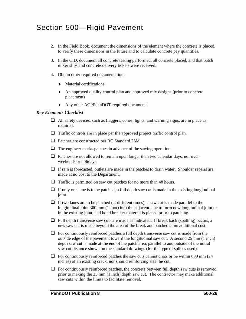
Section 500—Rigid Pavement
2. In the Field Book, document the dimensions of the element where the concrete is placed, to verify these dimensions in the future and to calculate concrete pay quantities.
3. In the CID, document all concrete testing performed, all concrete placed, and that batch mixer slips and concrete delivery tickets were received.
4. Obtain other required documentation:
♦ Material certifications
♦ An approved quality control plan and approved mix designs (prior to concrete placement)
♦ Any other ACI/PennDOT-required documents
Key Elements Checklist All safety devices, such as flaggers, cones, lights, and warning signs, are in place as
required.
Traffic controls are in place per the approved project traffic control plan.
Patches are constructed per RC Standard 26M.
The engineer marks patches in advance of the sawing operation.
Patches are not allowed to remain open longer than two calendar days, nor over weekends or holidays.
If rain is forecasted, outlets are made in the patches to drain water. Shoulder repairs are made at no cost to the Department.
Traffic is permitted on saw cut patches for no more than 48 hours.
If only one lane is to be patched, a full depth saw cut is made in the existing longitudinal joint.
If two lanes are to be patched (at different times), a saw cut is made parallel to the longitudinal joint 300 mm (1 foot) into the adjacent lane to form new longitudinal joint or in the existing joint, and bond breaker material is placed prior to patching.
Full depth transverse saw cuts are made as indicated. If break back (spalling) occurs, a new saw cut is made beyond the area of the break and patched at no additional cost.
For continuously reinforced patches a full depth transverse saw cut is made from the outside edge of the pavement toward the longitudinal saw cut. A second 25 mm (1 inch) depth saw cut is made at the end of the patch area, parallel to and outside of the initial saw cut distance shown on the standard drawings (for the type of splices used).
For continuously reinforced patches the saw cuts cannot cross or be within 600 mm (24 inches) of an existing crack, nor should reinforcing steel be cut.
For continuously reinforced patches, the concrete between full depth saw cuts is removed prior to making the 25 mm (1 inch) depth saw cut. The contractor may make additional saw cuts within the limits to facilitate removal.
PennDOT Publication 8 500-26
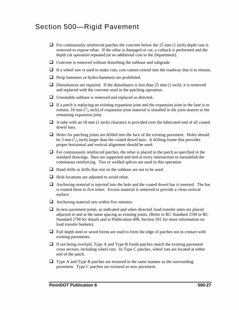
Section 500—Rigid Pavement
For continuously reinforced patches the concrete below the 25 mm (1 inch) depth cuts is removed to expose rebar. If the rebar is damaged or cut, a cutback is performed and the depth cut operation repeated (at no additional cost to the Department).
Concrete is removed without disturbing the subbase and subgrade.
If a wheel saw is used to make cuts, cuts cannot extend into the roadway that is to remain.
Drop hammers or hydro-hammers are prohibited.
Disturbances are repaired. If the disturbance is less than 25 mm (1 inch), it is removed and replaced with the concrete used in the patching operation.
Unsuitable subbase is removed and replaced as directed.
If a patch is replacing an existing expansion joint and the expansion joint in the lane is to remain, 18 mm (3/4 inch) of expansion joint material is installed in the joint nearest to the remaining expansion joint.
A tube with an 18 mm (1 inch) clearance is provided over the lubricated end of all coated dowel bars.
Holes for patching joints are drilled into the face of the existing pavement. Holes should be 3 mm (1/8 inch) larger than the coated dowel bars. A drilling frame that provides proper horizontal and vertical alignment should be used.
For continuously reinforced patches, the rebar is placed in the patch as specified in the standard drawings. Bars are supported and tied at every intersection to reestablish the continuous reinforcing. Ties or welded splices are used in this operation
Hand drills or drills that rest on the subbase are not to be used.
Hole locations are adjusted to avoid rebar.
Anchoring material is injected into the hole and the coated dowel bar is inserted. The bar is rotated three to five times. Excess material is removed to provide a clean vertical surface.
Anchoring material sets within five minutes.
In new pavement joints, as indicated and when directed, load transfer units are placed adjacent to and at the same spacing as existing joints. (Refer to RC Standard 21M or RC Standard 27M for details and to Publication 408, Section 501 for more information on load transfer baskets).
Full depth steel or wood forms are used to form the edge of patches not in contact with existing pavements.
If not being overlaid, Type A and Type B finish patches match the existing pavement cross section, including wheel ruts. In Type C patches, wheel ruts are located at either end of the patch.
Type A and Type B patches are textured in the same manner as the surrounding pavement. Type C patches are textured as new pavement.
PennDOT Publication 8 500-27
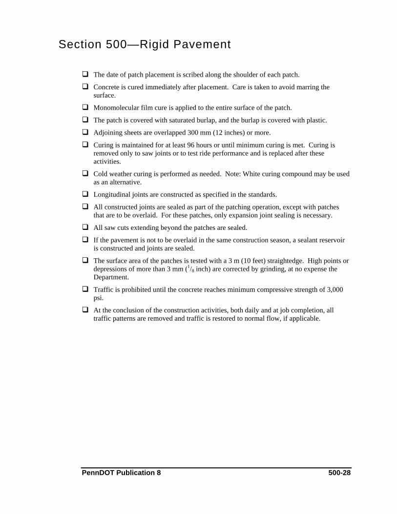
Section 500—Rigid Pavement
The date of patch placement is scribed along the shoulder of each patch.
Concrete is cured immediately after placement. Care is taken to avoid marring the surface.
Monomolecular film cure is applied to the entire surface of the patch.
The patch is covered with saturated burlap, and the burlap is covered with plastic.
Adjoining sheets are overlapped 300 mm (12 inches) or more.
Curing is maintained for at least 96 hours or until minimum curing is met. Curing is removed only to saw joints or to test ride performance and is replaced after these activities.
Cold weather curing is performed as needed. Note: White curing compound may be used as an alternative.
Longitudinal joints are constructed as specified in the standards.
All constructed joints are sealed as part of the patching operation, except with patches that are to be overlaid. For these patches, only expansion joint sealing is necessary.
All saw cuts extending beyond the patches are sealed.
If the pavement is not to be overlaid in the same construction season, a sealant reservoir is constructed and joints are sealed.
The surface area of the patches is tested with a 3 m (10 feet) straightedge. High points or depressions of more than 3 mm (1/8 inch) are corrected by grinding, at no expense the Department.
Traffic is prohibited until the concrete reaches minimum compressive strength of 3,000 psi.
At the conclusion of the construction activities, both daily and at job completion, all traffic patterns are removed and traffic is restored to normal flow, if applicable.
PennDOT Publication 8 500-28

Section 500—Rigid Pavement 9. Thin Bonded Portland Cement Concrete Overlay
This chapter addresses the construction of a thin bonded Portland cement concrete overlay or inlay, including surface preparation and joint sawing and sealing.
References Publication 408, Section 524 (Thin Bonded Portland Cement Concrete Overlay)
Publication 408, Section 501 (Reinforced or Plain Cement Concrete Pavements)
Publication 408, Section 704 (Cement Concrete)
Approved Quality Control Plans
Approved Traffic Control Plans
Approved Source of Supply
Material & Equipment Materials for the work include Class AA cement concrete, concrete admixtures, concrete cure, joint sealant, joint backing, tape bond breaker, and grout. All materials must be from an approved source of supply.
The contractor uses a self-propelled mechanical scarifier capable of uniformly removing the old surface to the depth indicated. Shot blasting, water blasting, or sand blasting equipment, capable of removing loose concrete and or rust from exposed rebar, is also used. The contractor also uses concrete saws, a 15-pound chipping hammer, and an air compressor. Paving equipment used to place the concrete must meet the specifications of Publication 408, Section 501. The contractor also needs concrete testing equipment as specified in Publication 408, Section 704.
Construction Methods After a PennDOT representative defines the limits of the overlay, the contractor scarifies the existing surface with a mechanical scarifier. Where necessary, the contractor may use shot blasting, water, sandblasting, or a chipping hammer. The remaining pavement is sounded to ensure all loose, deteriorated material has been removed.
Existing longitudinal and transverse joints are marked and the contractor cleans the surface prior to the placement of grout. The contractor’s certified technician tests the concrete, then the concrete is placed per standards and specifications. Joints are sawed and filled with an approved sealant.
Measuring & Payment Methods Surface preparation is paid by the square meter (square yard), as is extra-depth surface preparations and Portland cement concrete overlay.
PennDOT Publication 8 500-29

Section 500—Rigid Pavement Documentation
1. On the PSA, document:
♦ An item description and location
♦ Details of the overlay operation, including manpower, materials, testing, and equipment
♦ Reference to the Field Book and CID
♦ Payment. If applicable, indicate partial payments, as agreed to by the contractor, and
2. In the Field Book, document the dimensions of the element where the concrete is placed, to verify these dimensions in the future and to calculate concrete pay quantities.
3. In the CID, document all concrete testing performed, all concrete placed, and that batch mixer slips and concrete delivery tickets were received.
4. Obtain other required documentation:
♦ Material certifications
♦ An approved quality control plan and approved mix designs (prior to concrete placement)
♦ Any other ACI/PennDOT-required documents
Key Elements Checklist All safety devices, such as flaggers, cones, lights, and warning signs, are in place as
required.
Traffic controls are in place per the approved project traffic control plan.
Pavement surface is scarified to the indicated depth.
Exposed or loose rebar is cut off and removed.
Any deteriorated concrete is removed.
Pavement is sounded to ensure that deteriorated and delaminated concrete is removed.
If inlaying, existing transverse steel plates are removed.
The scarified pavement is cleaned and covered with polyethylene sheeting the day before the operation begins. Sheeting is removed at 30 m (100 feet) intervals in front of the operation.
The surface is cleaned with compressed air immediately before grouting and is kept clean.
All longitudinal and transverse joints are marked so that they can be located after overlay. The engineer approves the method for marking joints.
PennDOT Publication 8 500-30

Section 500—Rigid Pavement
Grout used has the consistency of latex paint. If course aggregate is visible after the operation, the grout is too thin.
Grout is mixed on site, no more than 90 minutes prior to placement.
Grout is placed immediately ahead of paver and an even coating is applied.
Concrete is placed before the grout has dried. If the grout starts to dry before the concrete is placed, it must be removed and replaced.
Bond strength is checked after seven days. Three cores are obtained, as directed. Acceptable bond strength is 200 psi at seven days. If the average of the three cores is below the acceptable strength, the area is considered defective. Cores are obtained every 9 m (30 feet) in each direction of the defective core to determine the limits of the defective work.
Concrete slump of 25 mm to 50 mm (1 inch to 2 inches) is provided for slipform paving and 50 mm to 75 mm (2 inches to 3 inches) for fixed form paving.
Curing is completed using only burlap or white concrete curing.
Joint backing material is placed in the existing transverse joints prior to overlay.
Joints are saw cut to the full depth of the overlay, directly over the existing joint, and to the width of the existing joint.
A sealant reservoir is constructed as in standard drawings. Backer material is placed and joint is sealed.
Maximum edge slump allowed in the outside (150 mm or 6 inches next to shoulder) is 6 mm (1/4 inch). Maximum allowed in the inside (150 mm or 6 inches next to additional lane) is 3 mm (1/8 inch).
Concrete is sounded prior to opening to traffic to determine if newly placed overlay has bonded. Defective areas are replaced.
Traffic is not permitted on the surface until the concrete has reached 3,000 psi.
Defective pavement overlay is removed and replaced.
At the conclusion of the construction activities, both daily and at job completion, all traffic patterns are removed and traffic is restored to normal flow, if applicable.
PennDOT Publication 8 500-31
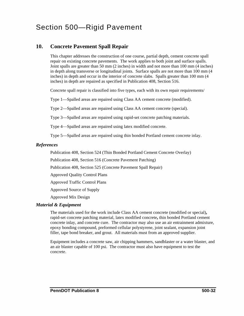
Section 500—Rigid Pavement 10. Concrete Pavement Spall Repair
This chapter addresses the construction of one course, partial depth, cement concrete spall repair on existing concrete pavements. The work applies to both joint and surface spalls. Joint spalls are greater than 50 mm (2 inches) in width and not more than 100 mm (4 inches) in depth along transverse or longitudinal joints. Surface spalls are not more than 100 mm (4 inches) in depth and occur in the interior of concrete slabs. Spalls greater than 100 mm (4 inches) in depth are repaired as specified in Publication 408, Section 516.
Concrete spall repair is classified into five types, each with its own repair requirements/
Type 1—Spalled areas are repaired using Class AA cement concrete (modified).
Type 2—Spalled areas are repaired using Class AA cement concrete (special).
Type 3—Spalled areas are repaired using rapid-set concrete patching materials.
Type 4—Spalled areas are repaired using latex modified concrete.
Type 5—Spalled areas are repaired using thin bonded Portland cement concrete inlay.
References Publication 408, Section 524 (Thin Bonded Portland Cement Concrete Overlay)
Publication 408, Section 516 (Concrete Pavement Patching)
Publication 408, Section 525 (Concrete Pavement Spall Repair)
Approved Quality Control Plans
Approved Traffic Control Plans
Approved Source of Supply
Approved Mix Design
Material & Equipment The materials used for the work include Class AA cement concrete (modified or special), rapid-set concrete patching material, latex modified concrete, thin bonded Portland cement concrete inlay, and concrete cure. The contractor may also use an air entrainment admixture, epoxy bonding compound, preformed cellular polystyrene, joint sealant, expansion joint filler, tape bond breaker, and grout. All materials must from an approved supplier.
Equipment includes a concrete saw, air chipping hammers, sandblaster or a water blaster, and an air blaster capable of 100 psi. The contractor must also have equipment to test the concrete.
PennDOT Publication 8 500-32

Section 500—Rigid Pavement Construction Methods
The contractor (under the supervision of a PennDOT representative) tests the area with a light hammer to define the limits of delineation. Spall areas are prepared per the specifications. Loose concrete is removed and the area is scarified as required.
After cleaning and sandblasting the area as required, the contractor applies the grout and epoxy bonding compound. The contractor’s certified technician tests the concrete, then the concrete is applied. Curing is applied as required.
Measuring & Payment Methods Spall repair, regardless of type, is paid by the square meter (square yard). Joint sealing is paid by the meter (linear foot).
Documentation 1. On the PSA, document:
♦ An item description and location
♦ Details of the repair operation, including manpower, materials, testing, and equipment
♦ Reference to the Field Book (if applicable) and CID
♦ Payment. If applicable, indicate partial payments, as agreed to by the contractor, and
2. In the CID, document all concrete testing performed, all concrete placed, and that batch mixer slips and concrete delivery tickets were received.
3. Obtain other required documentation:
♦ Material certifications
♦ An approved quality control plan and approved mix designs (prior to concrete placement)
♦ Any other ACI/PennDOT-required documents
Key Elements Checklist All safety devices, such as flaggers, cones, lights, and warning signs, are in place as
required.
Traffic controls are in place per the approved project traffic control plan.
Pavement around spalls is sounded with a light hammer to detect delaminated areas.
The area to be replaced is marked approximately 75 mm (3 inches) beyond delaminated areas.
All repairs are marked out square.
PennDOT Publication 8 500-33
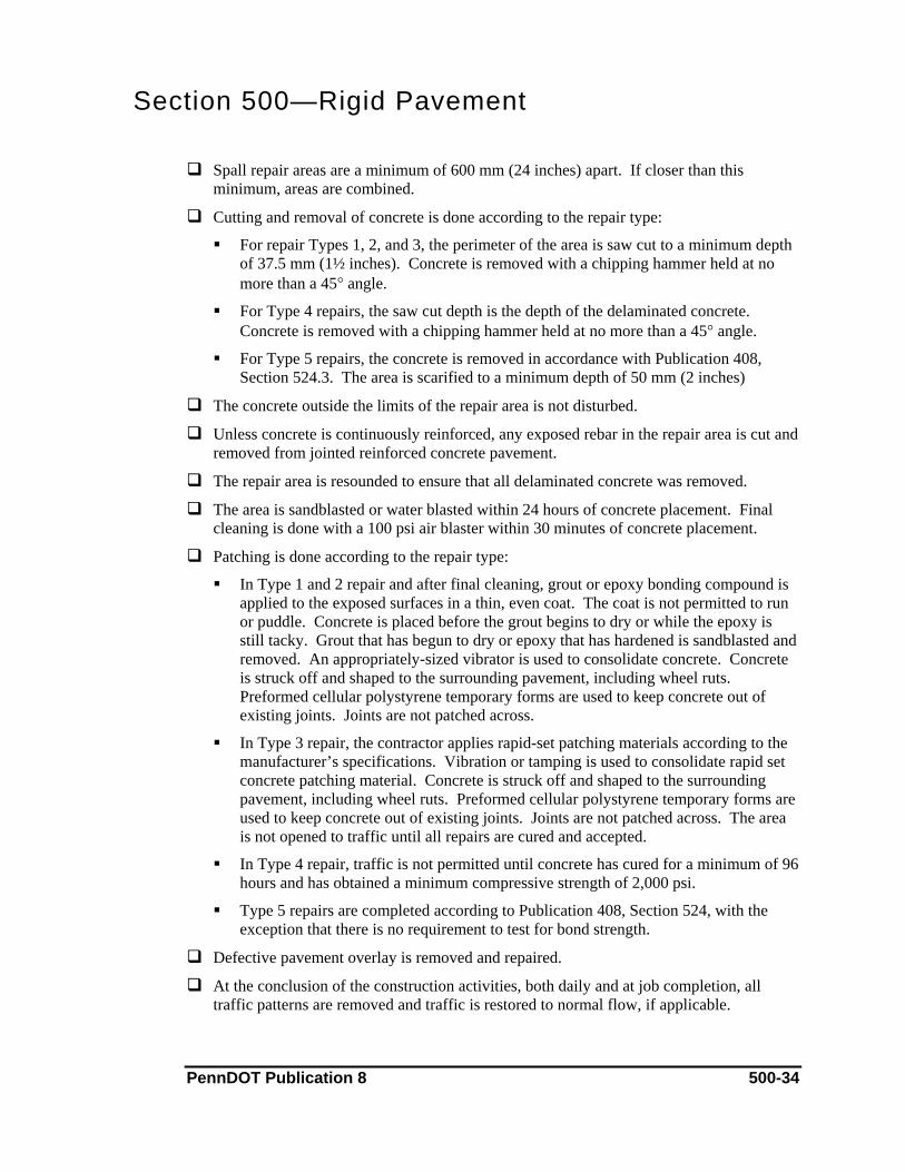
Section 500—Rigid Pavement
Spall repair areas are a minimum of 600 mm (24 inches) apart. If closer than this minimum, areas are combined.
Cutting and removal of concrete is done according to the repair type:
For repair Types 1, 2, and 3, the perimeter of the area is saw cut to a minimum depth of 37.5 mm (1½ inches). Concrete is removed with a chipping hammer held at no more than a 45° angle.
For Type 4 repairs, the saw cut depth is the depth of the delaminated concrete. Concrete is removed with a chipping hammer held at no more than a 45° angle.
For Type 5 repairs, the concrete is removed in accordance with Publication 408, Section 524.3. The area is scarified to a minimum depth of 50 mm (2 inches)
The concrete outside the limits of the repair area is not disturbed.
Unless concrete is continuously reinforced, any exposed rebar in the repair area is cut and removed from jointed reinforced concrete pavement.
The repair area is resounded to ensure that all delaminated concrete was removed.
The area is sandblasted or water blasted within 24 hours of concrete placement. Final cleaning is done with a 100 psi air blaster within 30 minutes of concrete placement.
Patching is done according to the repair type:
In Type 1 and 2 repair and after final cleaning, grout or epoxy bonding compound is applied to the exposed surfaces in a thin, even coat. The coat is not permitted to run or puddle. Concrete is placed before the grout begins to dry or while the epoxy is still tacky. Grout that has begun to dry or epoxy that has hardened is sandblasted and removed. An appropriately-sized vibrator is used to consolidate concrete. Concrete is struck off and shaped to the surrounding pavement, including wheel ruts. Preformed cellular polystyrene temporary forms are used to keep concrete out of existing joints. Joints are not patched across.
In Type 3 repair, the contractor applies rapid-set patching materials according to the manufacturer’s specifications. Vibration or tamping is used to consolidate rapid set concrete patching material. Concrete is struck off and shaped to the surrounding pavement, including wheel ruts. Preformed cellular polystyrene temporary forms are used to keep concrete out of existing joints. Joints are not patched across. The area is not opened to traffic until all repairs are cured and accepted.
In Type 4 repair, traffic is not permitted until concrete has cured for a minimum of 96 hours and has obtained a minimum compressive strength of 2,000 psi.
Type 5 repairs are completed according to Publication 408, Section 524, with the exception that there is no requirement to test for bond strength.
Defective pavement overlay is removed and repaired.
At the conclusion of the construction activities, both daily and at job completion, all traffic patterns are removed and traffic is restored to normal flow, if applicable.
PennDOT Publication 8 500-34
Section 500—Rigid Pavement 11. Rubblizing of Concrete Pavements
The chapter addresses rubblizing and seating of existing concrete pavements prior to pavement overlay. Rubblizing comprises two types:
Type 1—rubblizing pavement in to pieces with a maximum horizontal direction of 300 mm (12 inches).
Type 2—rubblizing pavement in to pieces with a maximum horizontal dimension of 200 mm (8 inches), with at least 50% of the pieces in each square yard having a maximum horizontal dimension of 100 mm (4 inches).
References Publication 408, Section 526 (Rubblizing of Concrete Pavements)
Approved Traffic Control Plans
Approved Rubblizing Plan
Material & Equipment Material for the work may include coarse aggregate to fill excavations. This material must be from an approved supplier.
Equipment for the work includes mechanical or sonic rubblizing equipment and a 50-ton pneumatic-tired roller.
Construction Methods The contractor removes the bituminous pavement overlaying concrete that is to be rubblized. This material is then rubblized using mechanical or sonic equipment. Depending on the specifications, concrete and reinforcing steel may be required to be free of bond.
The contractor seats the rubblized pavement with a pneumatic tired roller. The surface is cleaned and loose material is removed.
Measuring & Payment Methods Rubblizing and seat concrete pavement is paid by the square meter (square yard). Payment for Class 1A excavation, Class 1B excavation, and coarse aggregate is based on volume (cubic meter [cubic yard]).
Documentation 1. On the PSA, document:
♦ An item description and location
♦ Details of the operation, including manpower, materials, testing, and equipment
♦ Payment. If applicable, indicate partial payments, as agreed to by the contractor, and reference any documentation that may have a schedule of payments
PennDOT Publication 8 500-35
Section 500—Rigid Pavement
2. Obtain other required documentation:
♦ Material certification, if applicable
♦ An approved quality control plan
♦ Any other PennDOT-required documents
Key Elements Checklist All safety devices, such as flaggers, cones, lights, and warning signs, are in place as
required.
Traffic controls are in place per the approved project traffic control plan.
The approved rubblizing plan is followed.
Before the rubblizing process begins, overlaying bituminous material is removed.
Mechanical or sonic equipment capable of rubblizing concrete through full depth is used.
For Type 2 rubblizing, pieces are free of bond with reinforcement to ensure proper seating.
Two full depth 0.9 m x 3.6 m (3 feet by 12 feet) sections of rubblized pavement are excavated within the first 1.0 km (½ mile) of the operation to ensure proper rubblization. This is repeated whenever some aspect of the operation changes. Excavated area areas are filled with coarse aggregate in 150 mm (6 inches) lifts
Any exposed rebar at the surface is cut off and removed.
Any steel plates in the concrete joints are removed.
Care is used to prevent shattering the pavement edges adjacent to bituminous base repairs.
Extreme care is used to prevent damage to underground utilities, drainage, approach slabs, and bridge decks. Repairs to these areas are made at no cost to Department.
A pneumatic-tired roller (not a vibratory roller) is used to seat the rubblized pavement. All areas are rolled.
The final seating is satisfactory when vertical deflection under roller is less that 18 mm (¾ inch).
Unsatisfactory areas are undercut and unsuitable material is removed.
Approval is obtained from the bridge engineer before 50-ton rollers are permitted to cross bridges.
After final seating, the surface is cleaned and swept.
Traffic is prohibited on the roadway after this operation.
Overlay is completed within 60 days of final seating.
PennDOT Publication 8 500-36
Section 500—Rigid Pavement
Rubblized pavement is not exposed to freezing conditions.
At the conclusion of the construction activities, both daily and at job completion, all traffic patterns are removed and traffic is restored to normal flow, if applicable.
PennDOT Publication 8 500-37
Section 500—Rigid Pavement
This Page Left Intentionally Blank
PennDOT Publication 8 500-38

Section 600—Incidental Construction
Table of Contents 1. Pipe Culverts..........................................................................................................................600-1
A. Endwalls, Inlets, Manholes, and Spring Boxes............................................................600-5 2. Grade Adjustment of Existing Miscellaneous Structures ......................................................600-8 3. Rebuilt Miscellaneous Structures ........................................................................................600-11 4. Pipe Underdrain and Pavement Base Drain.........................................................................600-14 5. Subgrade Drains ..................................................................................................................600-16 6. Stone Backfill for Miscellaneous Drainage.........................................................................600-18 7. Subsurface Drain Outlet ......................................................................................................600-20 8. End Sections and Slope Pipe Fittings ..................................................................................600-22 9. Slotted Drains ......................................................................................................................600-24 10. Concrete Collar for Pipe Extension .....................................................................................600-26 11. Permanent Impact Attenuating Devices ..............................................................................600-29 12. Guide Rails ..........................................................................................................................600-31 13. Metal Median Barriers.........................................................................................................600-34 14. Concrete Glare Screen .........................................................................................................600-37 15. Concrete Median Barrier .....................................................................................................600-40 16. Right-of-Way Fence ............................................................................................................600-43 17. Gabions................................................................................................................................600-46 18. Curbs and Gutters ................................................................................................................600-48
A. Plain Cement Concrete Curb .....................................................................................600-48 B. Plain Concrete Mountable Curb.................................................................................600-51 C. Bituminous Concrete Curb ........................................................................................600-54 D. Plain Cement Concrete Gutter and Curb Gutter ........................................................600-56
19. Shoulder Rumble Strips.......................................................................................................600-59 20. Brick Masonry .....................................................................................................................600-61 21. Modular Architectural Block System ..................................................................................600-64 22. Cement Concrete Paving for Stream Beds ..........................................................................600-66 23. Pre-Cast Cement Concrete Block Slope Wall, Cast-in-Place Cement Concrete Slope
Wall .....................................................................................................................................600-69 24. Stone Slope Walls................................................................................................................600-72 25. Random Stone Slope Wall...................................................................................................600-75
PennDOT Publication 8 600-i

Section 600—Incidental Construction 26. Cement Concrete Sidewalks ................................................................................................600-78 27. Selected Material Surfacing.................................................................................................600-81 28. Permanent Barricades ..........................................................................................................600-83 29. Slab Stabilization.................................................................................................................600-85 30. Waterproofing......................................................................................................................600-88 31. Slabjacking ..........................................................................................................................600-90 32. Construction Surveying .......................................................................................................600-92 33. Built-Up Curb Ramps..........................................................................................................600-94 34. Temporary Impact Attenuating Devices and Reset Temporary Impact Attenuating
Devices ................................................................................................................................600-96
PennDOT Publication 8 600-ii
Section 600—Incidental Construction
1. Pipe Culverts Corrugated Metal Pipe-Arch Culverts
Metal Plate Culverts
Combination Storm Sewer and Underdrain
This chapter addresses the construction or reconstruction of pipe culverts, construction or reconstruction of corrugated metal pipe-arch culverts, construction of metal plate pipes, metal plate pipe-arches, metal plate arch culverts and the construction of a combinations storm sewer and underdrain.
References Publication 408, Section 601 (Pipe Culverts)
Publication 408, Section 602 (Corrugated Metal Pipe - Arch Culverts
Publication 408, Section 603 (Metal Plate Culverts)
Publication 408, Section 604 (Combination Storm Sewer and Underdrain)
Publication 408, Section 703 (Aggregates)
Publication 408, Section 735 (Geotextiles)
RC Standard 30M (Subsurface Drains)
RC Standard 32M (Slope Pipe Fittings, Pipe Connections)
RC Standard 33M (End Sections for Pipe Culverts)
Publication 2, Project Office Manual, Part C, Section 6 (Incidental Construction)
Publication 2, Project Office Manual, Part A, Section 2 (Shop Inspection)
Publication 213 (Traffic Control), if required
Material & Equipment Pipe culverts can be made from reinforced concrete, ductile iron, corrugated metallic coated steel, corrugated aluminum alloy, coated corrugated galvanized steel, polyethylene, and polyvinyl chloride. The materials used to manufacture the pipe must meet the requirements
PennDOT Publication 8 600-1
Section 600—Incidental Construction
of Publication 408, Section 601. The pre-cast reinforced concrete pipe should be inspected and stamped by the manufacturer’s inspector and should arrive on the project with the inspection stamp as outlined in Publication 2, Project Office Manual. The pipe should be thoroughly checked (inside and outside) for visible damage, including cracks, chip and spalls. In addition to the pipe, the contractor must use (AASHTO) No. 8 coarse aggregate for pipe trench bedding and No. 2A coarse aggregate for pipe trench backfill. Coarse aggregates must meet the requirements of Publication 408, Section 703 and RC Standard 30M. All material used must be from the suppliers listed on the contractor’s approved material source of supply. The material used for corrugated metal pipe-arch culverts are outlined in Publication 408, Sections 601 and 602. The contractor uses No. 2A coarse aggregate as pipe bedding and pipe trench backfill. The coarse aggregate must meet the requirements of Publication 408, Section 703 and must be free of foreign material. All material used must be from the suppliers listed on the contractor’s approved material source of supply. The materials used to manufacture metal plate pipes, metal plate pipe arches, and metal plate arches are outlined in Publication 408, Section 603. The contractor must submit shop drawings, showing all physical properties of the plates and joint design, for approval. All material used must be from the suppliers listed on the contractor’s approved material source of supply. No. 2A coarse aggregate is used as bedding and backfill material per RC Standard 30M. This material is usually stored at an approved 2A coarse aggregate supplier. The type of material used for the pipe fabrication of combination storm sewer and underdrain is determined by plan documents and must meet the requirements shown in Publication 408, Section 604. The No. 57 coarse aggregate used for backfill, as shown on RC Standard 30M, must meet the requirements of Publication 408, Section 703. The Class 1 geotextile that is shown on RC Standard 30M for encasement of the No. 57 aggregate must meet the requirements shown in Publication 408, Section 735. The pipe could be either reinforced concrete pipe (RCP) or perforated metal pipe. If RCP is used, it must be inspected and stamped by the manufacturer’s inspector and should arrive on the project stamped as outlined in Publication 2, Project Office Manual. When used to construct combination storm sewer and under drain, RCP is also referred to as “open-joint” pipe because the top portion of the pipe joints are left unsealed or open to allow groundwater to enter the pipe. All material used must be from the suppliers listed on the contractor’s approved material source of supply.
The contractor would need an excavator, such as a backhoe, excavator, trencher or gradall, to excavate the pipe trench per RC Standard 30M. The contractor needs a roller or a mechanical tamper to compact the bottom of the trench and to compact trench backfill according to RC Standard 30M and Publication 408, Section 601. The contractor needs a front loader or excavator to place the trench bedding and backfill per the requirements of Publication 408, Section 601 and RC Standard 30M. A dump truck is necessary to haul excess excavated material from the pipe trench to an approved waste area.
The contractor needs a survey instrument to lay out the location of and to set elevations for the placement. The contractor needs a level and string line or an electronic laser system to control the alignment and grade of the pipe trench excavation and pipe placement, as well as a nuclear gauge to check the density of the trench backfill after compaction. The contractor may also need a shore box for the excavation, depending on the depth of trench and the type of material the trench is in (as outlined in OSHA Standards).
PennDOT Publication 8 600-2

Section 600—Incidental Construction
The inspector should have a measuring device (tape measure, 6-foot rule, survey rod) to measure the pipe trench width and depth in m (feet).
Construction Methods If required, traffic control is established per Publication 213. The contractor lays out the pipe run; a level and string line or electronic laser system is set up to control the alignment and grade of the excavation. The contractor then excavates the pipe trench to the dimensions shown on RC Standard 30M for the type and size of pipe being placed and, if required by OSHA standards, places a shore box in the trench. The “bell” end of the pipe is always upstream of the flow. To properly tie the pipe into the inlet box, the bell end must be cut off. After the pipe is tied into the inlet box, the void around the pipe and box is sealed with grouted inside and outside. Occasionally, the void is too large for grout; in these situations, the void is sealed with bricks and grout. The bricks are then parged to reinforce the seal. The construction of metal plate pipes, metal plate pipe arches, and metal plate arch culverts is performed as outlined in Publication 408, Section 603. Bedding and backfill material is placed according to RC Standard 30M for the type of pipe being placed.
Measuring & Payment Methods Pipe culverts are paid by the meter (linear foot) for the total length of pipe placed. If the pipe runs from inlet to inlet, the pipe is measured from the inside face of the inlet box to the inside face of the inlet box. If the pipe does not connect to an inlet on both ends, the pipe is measured to the end as it protrudes from a slope or to its connection to an outlet item, such as an endwall. The pipe item includes all backfill and bedding material used in the placement.
Metal plate pipes and pipe arches are paid by the meter (linear foot). Bedding, backfill and concrete paving are incidental to the placement.
Combination storm sewer and underdrain excavation is paid by the cubic meter (cubic yard) for the type indicated. This is field measured, with computations and payment shown on a PSA. Class 1 geotextile is paid by the meter (linear foot); this is also field measured, and documented and paid on a PSA. No. 57 coarse aggregate is paid by the cubic meter (cubic yard). This, too, is field measured, with computations and payment shown on a PSA. Computation of the No. 57 coarse aggregates requires a deduction of the volume of pipe placed. CDS NeXtGen contains a program to assist with this calculation, see your CDS Operator for guidance. Class 1 excavation, if required by RC Standard 30M, is paid by the cubic meter (cubic yard). Class 2 excavation for the installation of half-circle pipe (including bedding and anchors) is also paid by the cubic meter (cubic yard). Class 4 excavation is paid by the cubic meter (cubic yard) within the pay limits shown on RC Standard 30M.
Cleaning of existing pipes, if required, is paid by the meter (linear foot). All meter (linear foot) items and all cubic meter (cubic foot) items are field measured. Computations for cubic meter (cubic yard) must be shown on a PSA. The CDS NeXtGen software includes a pipe payment computation program, consult the CDS operator for guidance.
PennDOT Publication 8 600-3
Section 600—Incidental Construction Documentation
1. On the PSA, document:
♦ That the pipe placed was the proper size, type, and class indicated
♦ That any reinforced concrete pipe used was inspected and stamped at the fabrication facilities.
♦ The type of metal plate pipe, metal plate pipe arch, or the metal plate arch culvert placed and that it meets the requirements of the plan documents and the culvert excavation and backfill was performed per Publication 408, Sections 603 and 601 and RC Standard 30M
♦ That the pipe trench was excavated meeting the requirements of RC Standard 30M
♦ That bedding and pipe trench backfill was placed according to Publication 408, Section 601 and RC Standard 30M
♦ That backfill was placed and compacted in a manner meeting the requirements of Publication 408, Section 601 and RC Standard 30M
♦ How the contractor controlled the alignment and grade of the pipe (e.g., using a level and string line or laser)
♦ Station-to-station and offset from baseline where the pipe was placed
♦ Computations and payments
2. Document that that the compaction of the subbase was approved through visual non-movement under compaction equipment on Form TR-478A. If compaction was approved by nuclear density method, use Form TR-4276A.
Key Elements Checklist If required, traffic control is established per Publication 213.
Pipe is inspected for defects or damage.
Contractor controls alignment and grade of the pipe by an acceptable method.
Pipe trench is excavated per RC Standard 30M and OSHA Standards are followed.
Bedding material and backfill material are placed in a manner meeting the requirements of RC Standard 30M for the type of pipe used.
The contractor has an acceptable method for controlling water that may flow through or gather in the pipe trench. See Section 800, Chapter 11 (E & S Control Measures/Environmental Compliance).
Pipe trench backfill is compacted to the requirements shown on RC Standard 30M for the type of pipe placed.
The inspector accepts pipe trench backfill compaction either through the use of nuclear density or by visual non-movement under compaction equipment.
PennDOT Publication 8 600-4

Section 600—Incidental Construction
Corrugated metal pipe joints are connected properly with metal bands and bolts provided by the manufacturer.
Pipe joints are sealed as outlined in Publication 408, Section 601.
Material certification (Form CS-4171) is obtained from the contractor for all material incorporated into the work.
A. Endwalls, Inlets, Manholes, and Spring Boxes This subchapter addresses the construction of endwalls, inlets, manholes, and spring boxes.
References Publication 408, Section 605 (Endwalls, Inlets, Manholes, and Spring Boxes)
Publication 408, Section 704 (Cement Concrete)
Publication 408, Section 711 (Concrete Curing Material)
Publication 408, Section 714 (Pre-Cast Concrete Products)
Publication 408, Section 1001 (Cement Concrete Structures)
RC Standard 31M (Endwalls)
RC Standard 34M (Inlets)
RC Standard 39M (Standard Manholes)
Approved Concrete Quality Control Plan
Approved Concrete Mix Design
Publication 2, Project Office Manual, Part A, Section 2 (Shop Inspection)
Publication 213 (Traffic Control), if required
Material & Equipment The materials required to construct and place inlets, endwalls, manholes and spring boxes are outlined in Publication 408, Section 605 and RC Standards 31M, 34M, and 39M. If inlets, endwalls, manholes, or spring boxes are pre-cast at a fabrication plant, they must arrive on the project stamped by an inspector as outlined in Publication 2, Project Office Manual. They also must be stamped with the information required by Publication 408, Section 714. All material used must be from suppliers listed on the contractor’s approved material source of supply.
The contractor needs an excavator, such as a backhoe, excavator, or gradall, to excavate for the inlet, endwall, manhole, or spring box. The contractor needs a front loader or an excavator to place backfill material and a mechanical tamper to compact backfill. A dump truck is necessary to haul excess excavated material to an approved waste area.
If the contractor is placing pre-cast units, a backhoe, gradall, or excavator could be used to set these in place. If the unit is cast-in-place, the contractor needs concrete testing equipment
PennDOT Publication 8 600-5

Section 600—Incidental Construction
meeting the requirements of Publication 408, Section 704 to test the concrete as specified in Publication 408, Section 704 and the contractor’s concrete quality control plan.
A survey instrument is required to establish finish grades for the inlet, endwall, manhole, or spring box.
Construction Methods If required, traffic control is established per Publication 213.
The inlet, endwall, manhole, or spring box location is laid out and offset stakes are set with the bottom of box elevations. The contractor uses these to control the excavation. Excavation is completed and bedding is placed and compacted.
If cast-in-placed concrete is used, the contractor’s certified concrete technician tests the concrete in accordance with the specifications and the concrete quality control plan.
Forms are constructed to the dimensions shown on the standard drawings for the type indicated and concrete is placed. After the concrete is cured, the forms are removed and the structure is backfilled. The backfill material is compacted to visual non-movement under compaction equipment.
If the contractor uses pre-cast units, the bedding is prepared, the units are set into place, and the units are backfilled.
After the inlet box and the adjoining pipe is in place, a small amount of concrete is placed in the bottom of the box to create flow lines. The placed concrete is hand-troweled to create a depressed channel that ties in with the pipe.
Measuring & Payment Methods Inlets, manholes, and spring boxes are paid each complete in-place, which includes excavation and backfill of the structure. Endwalls can be paid each or by the cubic meter (cubic yard) for the class of concrete indicated. This item is field measured and computed on a PSA.
Endwall excavation is paid in cubic meter (cubic yard) for the class of excavation indicated, which is field measured. All computations are shown on a PSA.
Documentation 1. On the PSA, document:
♦ That the units were inspected on arrival
♦ That the fabricator of pre-cast units stamped them per Publication 408, Section 714 and Publication 2, Project Office Manual and that an inspector at the fabricator stamped them per Publication 2, Project Office Manual
♦ What type of unit the contractor was working on
PennDOT Publication 8 600-6

Section 600—Incidental Construction
♦ That the excavation was performed per RC standards and that calculations for concrete and excavation were documented
♦ Station-to-station and offset from baseline where the unit was located
♦ Computations and payments
2. In the CID, document all concrete testing performed, all concrete placed, and that batcher mixer slips and concrete delivery tickets were received.
3. Document that that the compaction of the subbase was approved through visual non-movement under compaction equipment on Form TR-478A. If compaction was approved by nuclear density method, use Form TR-4276A.
Key Elements Checklist If required, traffic control is established per Publication 213.
Pre-cast units are checked on arrival to ensure that an inspector at the fabricator has stamped them and that they are stamped with the proper information.
Units are checked for damage, such as crack, spalls, and missing steps.
The contractor constructs the indicated unit and at the location shown on plan at the correct elevation.
The unit, excavation, and backfill meet the requirements of Publication 408, Section 605 and RC Standards 31M, 34M, and 39M.
Compaction of backfill material to visual non-movement is witnessed and recorded on Form TR-478A (Compaction Density Non-Movement).
The finished grade and alignment of the unit is correct.
The contractor’s certified concrete technician has tested the concrete in accordance to the specifications and the concrete quality control plan. Test results are with the specified limits.
Air temperature conforms to specifications for concrete placement.
Material certification (Form CS-4171) is obtained from the contractor for all material incorporated into the work.
PennDOT Publication 8 600-7

Section 600—Incidental Construction 2. Grade Adjustment of Existing Miscellaneous Structures
This chapter addresses the grade adjustment of existing inlets, manholes, or utility boxes to a vertical height of 100 mm (4 inches) or less.
References Publication 408, Section 606 (Grade Adjustment of Existing Miscellaneous Structures)
Publication 408, Section 704 (Cement Concrete)
Publication 408, Section 711 (Concrete Curing Material)
Publication 408, Section 1001 (Cement Concrete Structures)
RC Standard 31M (Endwalls)
RC Standard 34M (Inlets)
RC Standard 39M (Standard Manholes)
Publication 2, Project Office Manual, Part A, Section 2 (Shop Inspection)
Approved Concrete Quality Control Plan
Approved Concrete Mix Design
Publication 213 (Traffic Control), if required
Material & Equipment The material used must conform to the requirements specified for new structures of the type indicated and meet the requirements of Publication 408, Section 606. Adjustments can be made with cast in place concrete or pre-cast extensions.
Sometimes, the contractor uses extensions that are pre-cast by a manufacturer listed in Bulletin 15 and from a fabricator listed on the contractor’s approved material source of supply. Pre-cast extensions must be inspected and stamped by the manufacturer’s inspector at the manufacturer and should arrive on the project stamped as outlined in Publication 2, Project Office Manual. All material used must be from suppliers listed on the contractor’s approved material source of supply.
The contractor needs equipment, such as a backhoe, excavator, or gradall, to excavate around the structure that is to be adjusted. A hand-held concrete saw may be needed to saw the existing structure at the limits of removal. An air compressor is necessary to run jack hammers to remove the existing structure and a mechanical tamper is needed to compact backfill material after the rehabilitation is complete.
If the structure adjustment involves cast-in-place concrete, concrete testing equipment is required. Generators may be needed to run the electrical hand tools for constructing forms. A dump truck is necessary to haul debris to an approved waste area.
PennDOT Publication 8 600-8
Section 600—Incidental Construction
A survey instrument is required to set grades for the structure that is to be raised. If the structure adjustments are cast-in-place, concrete testing equipment as specified in Publication 408, Section 704 would be used.
The inspector needs a device to measure vertical mm (vertical inches), such as a tape measure or an engineer’s rule, to check the height of the rebuilt structure.
Construction Methods If required, traffic control is established per Publication 213.
The contractor places off set grade stakes with finish grades marked on them at the structure to be adjusted and the structure is marked at the removal line. A concrete saw is used to saw the existing structure at the removal line (if removal is necessary). The saw cut is made about 25 mm (1 inch) deep.
The portion of the structure to be removed is removed using jackhammers. If a pre-cast unit is placed, the contractor places a full bed of mortar on the existing structure and sets the pre-cast unit in place. If the work involves cast-in-place concrete, the contractor’s certified concrete technician tests the concrete in accordance with the specifications and the concrete quality control plan. The contractor constructs forms and places reinforcement as required and places the required class of concrete. After the concrete is cured, the structure is backfilled. The backfill material is compacted to visual non-movement under compaction equipment.
Measuring & Payment Methods This item is paid by the set complete in place, which includes removing and cleaning the existing casting, constructing the structure walls to the required elevation, and replacing casting on a full mortar bed as required.
Documentation 1. On the PSA, document:
♦ The type of structure adjusted
♦ How the contractor removed the existing structure and how it was reconstructed
♦ That pre-cast units are from the contractor’s approved source of supply and that an inspector at the fabricator stamped them
♦ Station-to-station and offset from baseline where the work is to be performed
♦ How the structure was backfilled
♦ Computations and payments
2. In the CID, document all concrete testing performed, all concrete placed, and that batcher mixer slips and concrete delivery tickets were received.
PennDOT Publication 8 600-9

Section 600—Incidental Construction
3. Document that that the compaction of the subbase was approved through visual non-movement under compaction equipment on Form TR-478A. If compaction was approved by nuclear density method, use Form TR-4276A.
Key Elements Checklist If required, traffic control is established per Publication 213.
The adjustment to the structure is not greater than 100 mm (4 inches).
The contractor’s certified concrete technician has tested the concrete in accordance to the specifications and the concrete quality control plan. Test results are within specified limits.
Air temperature conforms to specifications for concrete placement.
If pre-cast units are used, they are from the contractor’s approved material source of supply.
The top of structure is set at finished grade.
Structures are backfilled according to standards and specifications.
Compaction of backfill material to visual non-movement is witnessed & recorded on form TR-478A.
Material certification (Form CS-4171) is obtained from the contractor for all material incorporated into the work.
PennDOT Publication 8 600-10
Section 600—Incidental Construction 3. Rebuilt Miscellaneous Structures
This chapter addresses the rebuilding of existing inlets, manholes, or utility boxes of heights in excess of 100 mm (4 inches).
References Publication 408, Section 606 (Grade Adjustment to Existing Miscellaneous Structures)
Publication 408, Section 607 (Rebuilt Miscellaneous Structures)
Publication 408, Section 704 (Cement Concrete)
Publication 408, Section 711 (Concrete Curing Material)
Publication 408, Section 1001 (Cement Concrete Structures)
RC Standard 31M (Endwalls)
RC Standard 34M (Inlets)
RC Standard 39M (Standard Manholes)
Publication 2, Project Office Manual, Part A, Section 2 (Shop Inspection)
Approved Concrete Quality Control Plan
Approved Concrete Mix Design
Publication 213 (Traffic Control), if required
Material & Equipment The material must conform to the requirements specified for new structures of the type indicated as outlined in Publication 408, Section 605. All material used must be from suppliers listed on the contractor’s approved material source of supply.
If cast-in-place concrete is used, it must meet the requirements of Publication 408, Section 704 and the contractors concrete quality control plan. If pre-cast risers are used, they must be inspected and stamped by the manufacturer’s inspector and should arrive on the project stamped.
The contractor needs equipment, such as a backhoe, excavator, or gradall, to excavate around the structure that is to be rebuilt. A hand-held concrete saw may be needed to saw the existing structure at the limits of removal. An air compressor and jackhammers are necessary to remove the existing structure and a mechanical tamper is needed to compact backfill material after the rebuild is complete.
If the structure rebuild involves cast-in-place concrete, concrete testing equipment is required. Electrical hand tools and the generators to run them may be needed in constructing forms. A dump truck is necessary to haul excess debris to an approved waste area.
A survey instrument is required to set grades for the rebuilt structure. If the structure rebuilds are cast-in-place, concrete testing equipment as specified in Publication 408, Section 704 would be used.
PennDOT Publication 8 600-11
Section 600—Incidental Construction
The inspector needs a device to measure vertical mm (vertical inches) to check the height of the structure.
Construction Methods If required, traffic control is established per Publication 213.
The contractor places offset stakes, with finish grades and alignment marked on them, on the shoulder of the road. A level and string line is used to match the finish grade and alignment, while the stakes are used to control the depth and alignment of the rebuilt portion of the structure.
The structure is marked at the removal line and cut about 25 mm (1 inch) deep at this line with a concrete saw. This creates a smooth edge. A jackhammer is used to remove the remaining portion of the structure. Debris from demolition is hauled to an approved waste area.
If pre-cast risers are used to rebuild the structure, a full bed of mortar is placed on the existing surface before placing the riser. If the rebuilt structure is cast-in-place, the contractor’s certified concrete technician tests the concrete in accordance with the specifications and the concrete quality control plan. The contractor constructs forms to grade and places the required class of concrete. After the concrete has cured, the structure is backfilled. The backfill material is compacted to visual non-movement under compaction equipment.
Measuring & Payment Methods Rebuilt items are paid by the vertical meter (vertical foot), which is field measured. Payment calculation is made on a PSA.
Documentation 1. On the PSA, document:
♦ The type of structure rebuilt
♦ Station and offset from baseline for the location of the structure being rebuilt
♦ The procedure the contractor used to remove portions of the existing structure
♦ The method used to rebuild the structure, such as cast-in-place or pre-cast units. If pre-cast units are used, document that the unit was inspected at the fabricator, stamped by the inspector, and that the pre-cast unit is from a supplier listed on the contractor’s approved source of supply
♦ How the structure was backfilled and compacted
♦ Computations and payments
2. In the CID, document all concrete testing performed, all concrete placed, and that batcher mixer slips and concrete delivery tickets were received.
PennDOT Publication 8 600-12
Section 600—Incidental Construction
3. Document that that the compaction of the subbase was approved through visual non-movement under compaction equipment on Form TR-478A. If compaction was approved by nuclear density method, use Form TR-4276A.
Key Elements Checklist If required, traffic control is established per Publication 213.
Vertical adjustment is to grade and is greater than 100 mm (4 inches).
The contractor’s certified concrete technician has tested the concrete in accordance to the specifications and the concrete quality control plan. Test results are within specified limits.
Air temperature conforms to specifications for concrete placement.
If pre-cast units are used, they are from a supplier that is listed on the contractor’s approved source of supply.
The structure is rebuilt meeting the requirements of Publication 408, Section 605.
Rebuilt structures are backfilled per standards and specifications.
Compaction of backfill material to visual non-movement is witnessed & recorded on form TR-478A
Material certification (Form CS-4171) is obtained from the contractor for all material incorporated into the work.
PennDOT Publication 8 600-13
Section 600—Incidental Construction 4. Pipe Underdrain and Pavement Base Drain
This chapter addresses the construction of pipe underdrains and pavement base drains. The drains are used to channel water from the pavement area.
References Publication 408, Section 212 (Geotextiles)
Publication 408, Section 610 (Pipe Underdrain & Pavement Base Drain)
Publication 408, Section 703 (Aggregate)
RC Standard 30M (Subsurface Drains)
Publication 213 (Traffic Control), if required
Material & Equipment The material used to construct the pipe is outlined in Publication 408, Section 610 and must meet the requirements of the applicable Publication 408 sections. The coarse aggregate used for backfill must meet the requirements of Publication 408, Section 703 and RC Standard 30M for the type of pipe installation required. Class 1 geotextile used to encapsulate the coarse aggregate as shown on the standard drawings must meet the requirements of Publication 408, Section 212. All material used must be from the suppliers listed on the contractor’s approved material source of supply.
The contractor may use a trencher or backhoe to excavate the trench for the pavement base drain and underdrain. A trench roller or a mechanical tamper is needed to compact the bottom of the trench after it is excavated.
A vibratory plate is used to consolidate the coarse aggregate after it is placed atop the pipe, while a dump truck with a chute or a front-end loader is used to place aggregate in the trench.
The contractor needs a measuring device, such as a tape measure, to lay out the pipe location, which is then marked with marking paint. The inspector also needs a tape measure or folding rule to measure the pipe trench depth and width to ensure it is excavated according to the requirements of RC Standard 30M.
The contractor needs a survey instrument to control the grade of the pipe. Grade stakes are usually set every 15 m (50 feet).
Construction Methods If required, traffic control is established per Publication 213.
Pipe underdrains and pavement base drains are normally installed after the subbase is poured. The contractor marks out the pipe run with points and marks all outlets. Some outlets run out the slope on the side of the road, some connect to draining outlet boxes. The contractor then excavates the trench using a trencher or backhoe. The bottom of the trench is rolled with a trench roller or compacted with a mechanical tamper.
PennDOT Publication 8 600-14
Section 600—Incidental Construction
If geotextile is used, the trench is lined with the geotextile and a small amount of coarse aggregate is placed at the bottom of the trench prior to laying the pipe. The entire trench is then filled with coarse aggregate and consolidated with a vibratory plate compactor.
Measuring & Payment Methods Pipe underdrains, pavement base drains, and Class 1 geotextile are paid by the meter (linear foot). After installation, these are field measured and payment calculation is made on a PSA.
If the contractor is required to excavate the trench deeper than the depth shown on the standard drawing, the contractor is paid extra for anything over the required depth shown in the RC standards. This extra payment is made using Class 4 excavation. Additional coarse aggregate placed because of the extra trench excavation is paid by cubic meter (cubic yard). This is field measured and computed on a PSA.
Documentation On the PSA, document:
♦ The type and size of base drain or underdrain placed
♦ That the pipe trench was excavated and prepared per RC Standard 30M
♦ That the coarse aggregate used for backfill was the type indicated on RC Standard 30M and was consolidated using a vibratory plate tamper
♦ Station-to-station and the offset distance of the pipe placement
♦ Computations and payments
Key Elements Checklist If required, traffic control is established per Publication 213.
The coarse aggregate used is from a source that is listed on the contractors approved source of supply.
The trench is excavated to the dimensions shown on RC Standard 30M.
Aggregate, geotextile, and backfill are placed per RC Standard 30M.
Coarse aggregate used for backfill is consolidated using a vibratory plate tamper, as a roller could damage the pipe.
Excess excavated material from the pipe trench is hauled to an approved waste area.
Material certification (Form CS-4171) is obtained from the contractor for all material incorporated into the work.
PennDOT Publication 8 600-15

Section 600—Incidental Construction 5. Subgrade Drains
This chapter addresses the construction of a drain in the subgrade to channel water from under the pavement area. The subgrade drain is constructed when a water problem is encountered. In addition to channeling water, the drain helps to stabilize the subgrade and make a solid grade for the placement of the subbase.
References Publication 408, Section 612 (Subgrade Drains)
Publication 408, Section 735 (Geotextiles)
RC Standard 30M (Subsurface Drains)
Publication 213 (Traffic Control), if required
Material & Equipment The contractor uses a coarse aggregate as indicated in Publication 408, Section 612 and RC Standard 30M. Geotextile is used to enclose the coarse aggregate as indicated in RC Standard 30M. The geotextile must meet the requirements of Publication 408, Section 735. Where geotextile is not indicated, bituminous paper must be used as shown in the RC Standard 30M. All material used must be from the suppliers listed on the contractor’s approved material source of supply.
The contractor needs equipment such as a trencher, backhoe, or gradall to excavate the subgrade trench. The equipment must be capable of excavating the trench to the dimensions shown on RC Standard 30M for the type indicated.
A trench roller or mechanical tamper is required to compact the bottom of trench and to compact the backfill. The contractor also needs equipment, such as a dump truck with a chute, front-end loader or gradall, to place coarse aggregate backfill.
The contractor needs a survey instrument to control the grade of the trench. The inspector needs a device, such as a tape measure or engineering rule, to measure the width and depth of the subgrade drain trench to ensure it meets the requirements of RC Standard 30M.
Construction Methods If required, traffic control is established per Publication 213.
The inspector-in-charge lays out the location for the subgrade drain. The contractor, using an acceptable method, excavates the subgrade drain trench. A survey instrument is used to control the grade to ensure it meets the proper slope requirements.
The contractor places Class 1 geotextile, if required, in the bottom of the excavation. After the geotextile is placed, the contractor backfills with coarse aggregate per RC Standard 30M. The coarse aggregate is compacted using an acceptable method. If geotextile is not required, bituminous paper is placed on top of coarse aggregate backfill.
PennDOT Publication 8 600-16
Section 600—Incidental Construction Measuring & Payment Methods
Subgrade drains are paid by the meter (linear foot), which includes the backfill and bituminous paper used to place the drain. The subgrade drain is field measured and a payment is made on a PSA.
Geotextile is also paid the meter (linear foot). Geotextile is field measured, with payment is made on a PSA.
Documentation On the PSA, document:
♦ The reason a subgrade drain is needed and the location of the drain
♦ How the trench was excavated and the dimensions of the trench
♦ What type of coarse aggregate was used for backfill and, if required, that the subgrade drain was enclosed with Class 1 geotextile
♦ That the coarse aggregate backfill was compacted
♦ Computations and payments
Key Elements Checklist If required, traffic control is established per Publication 213.
The slope of the drain meets the requirements of Publication 408, Section 612.
The trench is excavated to the dimensions shown on RC Standard 30M.
The coarse aggregate used in the construction of the subgrade drain is from an approved source of supply.
Coarse aggregate backfill is compacted.
Subgrade drains are outleted.
Material certification (Form CS-4171) is obtained from the contractor for all material incorporated into the work.
PennDOT Publication 8 600-17

Section 600—Incidental Construction 6. Stone Backfill for Miscellaneous Drainage
This chapter addresses the furnishing and placing of stone backfill for miscellaneous drainage, such as sumps, springs, wells, and sink holes, as indicated or directed.
References Publication 408, Section 212 (Geotextiles)
Publication 408, Section 613 (Stone Backfill for Miscellaneous Drainage)
Publication 408, Section 703 (Aggregate)
Publication 213 (Traffic Control), if required
Material & Equipment The coarse aggregate used in this work is type C or better (such as No. 1 and No. 57 aggregate); steel slag is not to be used. The contractor, if allowed, can use acceptable clean, sound, hard, and durable slabs of local stone no larger than 150 mm (6 inches) in any dimension. If local stone is used, the contractor must place a 150 mm (6 inches) layer of No. 57 stone on top. All material used must be from the suppliers listed on the contractor’s approved material source of supply.
The coarse aggregate must meet the requirements of Publication 408, Section 703. Class 1 geotextile, meeting the requirements of Publication 408, Section 212 is used to enclose the coarse aggregate.
The contractor needs equipment capable of placing coarse aggregate, such as an excavator, gradall, backhoe or front-end loader. The equipment is acceptable if it can properly place the aggregate in the drainage structure.
The inspector needs a tape measure or engineering rule to measure trench excavation.
Construction Methods If required, traffic control is established per Publication 213.
This work is job-specific, as outlined in project documents. The contractor places the stone and geotextile according to the job requirements.
Measuring & Payment Methods This work is paid by the cubic meter (cubic yard). The aggregate backfill area is field measured, with computation and payment shown on a PSA.
Documentation On the PSA, document:
♦ Where the stone backfill was placed and for what reason
♦ The type of coarse aggregate used
PennDOT Publication 8 600-18
Section 600—Incidental Construction
♦ If the contractor used Class 1 geotextile
♦ If the use of local stone was permitted, it met the requirements of Publication 408, Section 613 and that No. 57 stone was placed on top in a 150 mm (6 inches) layer
♦ Computations and payments
Key Elements Checklist If required, traffic control is established per Publication 213.
Material used is the material outlined on contract documents for the type of work being performed.
Material used is from the supplier that is listed on the contractors approved source of supply.
Material certification (Form CS-4171) is obtained from the contractor for all material incorporated into the work.
PennDOT Publication 8 600-19

Section 600—Incidental Construction 7. Subsurface Drain Outlet
This chapter addresses the construction of subsurface drain outlets for pavement base drain and underdrain.
References Publication 408, Section 206 (Embankment)
Publication 408, Section 610 (Pipe Underdrain and Pavement Base Drain)
Publication 408, Section 615 (Subsurface Face Drain Outlets)
RC Standard 30M (Subsurface Drains)
RC Standard 31M (Endwalls)
TC Standard 7604 (Delineation)
Publication 213 (Traffic Control), if required
Material & Equipment Materials used in this work include a solid pipe meeting the requirements of Publication 408, Sections 615 and 610. Unless otherwise directed, the outlet pipe should be made of the same material as the underdrain or pavement base drain.
If indicated on the plans or as directed, the contractor needs concrete outlet endwalls for the end of outlet plastic pipes (meeting the requirements of RC Standard 31M). In addition, the contractor needs red flexible delineators, meeting the requirements of Publication 408, Section 615 and TC Standard 7604, to place at the endwall to mark the location (of the outlet. All material used must be from suppliers listed on the contractor’s approved material source of supply.
The contractor needs equipment such as a backhoe, gradall, excavator, or trencher capable of excavating the pipe trench to the dimensions shown on RC Standard 30M. A mechanical tamper is used to compact the pipe trench bottom and the backfill placed on top of the pipe. To place backfill material, the contractor needs a backhoe, front-end loader, gradall, or excavator. If pre-cast concrete endwalls are required, a backhoe is used to place them.
The contractor needs a survey instrument and a measuring device to lay out the outlets and to control the slope of the outlet pipe. The inspector needs a tape measure or engineering rule to check the dimensions of the pipe trench excavation and the dimensions of the concrete endwall to ensure that they meet the requirements of RC Standards 30M and 31M.
Construction Methods If required, traffic control is established per Publication 213.
The contractor lays out the outlet location and excavates the trench to the requirements of RC Standard 30M.and contract documents. A 50 mm (2 inches) layer of embankment material is then placed and compacted using a mechanical tamper.
PennDOT Publication 8 600-20
Section 600—Incidental Construction
The pipe is placed and connected to the base drain or underdrain with bands or split couplings. The outlet ends of the pipes are connected to the pre-cast or cast-in-place endwalls or outleted into an existing drainage structure. Cast-in-place endwalls must meet the requirements of RC Standard 31M.
After the pipe is placed, the trench is backfilled with embankment material. This backfill is placed in 100 mm (4 inches) lifts and thoroughly tamped. Lastly, if an endwall is used, a red flexible delineator is placed at the outlet to mark the location.
Measuring & Payment Methods The outlet pipe is paid by the meter (linear foot) and includes the excavation up to 900 mm (36 inch) depth. The pipe is field measured and paid on a PSA. If the contractor is required to excavate the trench over 900 millimeter (36 inch) in depth or 600 millimeter (24 inch) in width, the extra excavation is paid as Class 4 excavation in cubic meter (cubic yard). This is also field measured and computed on a PSA.
Each subsurface drain outlet endwall and red subsurface drain outlet markers are paid each. These are field counted and paid on a PSA.
Documentation On the PSA, document:
♦ The location for the outlet, what type of outlet, and size of pipe that was used
♦ That a concrete endwall was set, if required
♦ That the excavation and backfill of the pipe trench was done per RC Standard 30M
♦ That a red flexible delineator was placed at the endwall
♦ Computations and payments
Key Elements Checklist If required, traffic control is established per Publication 213.
Outlet pipe meets the requirements of Publication 408, Section 615.
The pipe has positive gravity flow to the outlet.
If plastic pipe is used, a concrete endwall is used on the outlet end.
The pipe trench is excavated and backfilled per the requirements of RC Standard 30M.
Material certification (Form CS-4171) is obtained from the contractor for all material incorporated into the work.
PennDOT Publication 8 600-21
Section 600—Incidental Construction 8. End Sections and Slope Pipe Fittings
The chapter addresses the construction of end sections and slope pipe fittings.
References Publication 408, Section 601 (Pipe Culverts)
Publication 408, Section 616 (End Sections & Slope Pipe Fittings)
Publication 408, Section 703 (Aggregates)
RC Standard 32M (Slope Pipe Fittings)
RC Standard 33M (End Sections for Pipe Culverts)
Publication 2, Project Office Manual, Part A, Section 2 (Shop Inspection)
Publication 2, Project Office Manual, Part C, Section 6 (Markings for Reinforced Concrete Pipe)
Publication 213 (Traffic Control), if required
Material & Equipment The end sections for pipe culverts can be made of concrete, metallic-coated steel, or aluminum alloy meeting the requirements of Publication 408, Section 601. The slope pipe fittings are made of steel that meets the requirements of Publication 408, Section 601 and RC Standard 32M. Coarse aggregate that meets the requirements of Publication 408, Section 703 is used for backfill as indicated for slope pipes in RC Standard 32M. All material used must be from the suppliers listed on the contractor’s approved material source of supply.
The contractor needs equipment, such as a backhoe, excavator, or gradall, to excavate for the end sections and slope pipe fittings. An excavator, backhoe, front-end loader, or gradall are used to place end sections and slope pipe fittings and then to backfill them. A mechanical tamper is needed to compact the backfill material.
The contractor needs a survey instrument to establish grade for the end section or slope pipe. The established grade is used to control the slope of the pipe to ensure it meets plan requirements. The contractor may also need a nuclear gauge to check the backfill compaction density.
Construction Methods If required, traffic control is established per Publication 213.
The contractor sets grades for the end section or slope pipe and excavates to these grades. The contractor then places the end section or slope pipe and backfills in 100 mm (4 inches) lifts to required compaction.
Measuring & Payment Methods End sections or slope pipe fittings are paid each on a PSA when they are completely in place. Payment includes excavation and backfill.
PennDOT Publication 8 600-22

Section 600—Incidental Construction Documentation
1. On the PSA, document:
♦ The type of end section or pipe fitting placed and that it meets the requirements of Publication 408, Sections 616 and 601 and RC Standards 32M and 33M
♦ The location of the end section or pipe fitting placed
♦ That the excavation, placement of end section or pipe fittings, and backfill was completed per Publication 408, Section 601 and RC Standards 32M and 33M
♦ Computations and payments
2. Document that that the compaction of the subbase was approved through visual non-movement under compaction equipment on Form TR-478A. If compaction was approved by nuclear density method, use Form TR-4276A.
Key Elements Checklist If required, traffic control is established per Publication 213.
The excavation, placement of end section, and backfill meet the requirements of Publication 408, Sections 615 and 601 and RC Standards 32M and 33M.
The end section or slope pipe fittings meet the requirements of the plan documents and specifications.
If concrete end sections are used, they have an inspection stamp and a stamp from the manufacturer with the requirements of Publication 2, Project Office Manual, Part C, Section 6.
Material certification (Form CS-4171) is obtained from the contractor for all material incorporated into the work.
Backfill compaction is accepted by the inspector either by the use of nuclear density or by visual non-movement under compaction equipment. If accepted using visual non-movement under compaction equipment, acceptance is recorded on Form TR-478A (Compaction Density Non-movement).
PennDOT Publication 8 600-23
Section 600—Incidental Construction 9. Slotted Drains
The chapter addresses the construction of drains with continuous slotted openings.
References Publication 408, Section 106 (Material Certification)
Publication 408, Section 350 (Subbase)
Publication 408, Section 617 (Slotted Drains)
Bulletin 15 (Approved Construction Materials)
RC Standard 30M (Subsurface Drains)
Publication 213 (Traffic Control), if required
Material & Equipment Slotted drains are fabricated from metallic coated steel pipes, meeting the requirements of Publication 408, Section 601, or pre-cast polymer concrete troughs as listed in Bulletin 15 and certified per Publication 408, Section 106. The coarse aggregate used to backfill around the slotted drain must meet the requirements of Publication 408, Section 350. All material used must be from the suppliers listed on the contractor’s approved material source of supply.
The contractor needs equipment such as a backhoe, excavator, or gradall capable of excavating the trench to the requirements of RC Standard 30M for pipe and to the manufacturer’s recommendations for pre-cast polymer concrete sections.
A backhoe, front loader, or excavator is used to place pipe in the trench and to backfill the material according to the requirements of Publication 408, Section 350. The contractor also needs compaction equipment such as a walk behind roller or mechanical tamper to compact the backfill material to the requirements of Publication 408, Section 350.
The contractor needs a survey instrument to lay out pipe and establish grades to control pipe placement. Grades for the pipe placement are marked on offset stakes. The contractor and the inspector both need a device, such as a tape measure or engineering rule, to measure the pipe trench to ensure it meets required specifications.
Construction Methods If required, traffic control is established per Publication 213.
The contractor lays out the pipe location and sets grade stakes to control the grade of the pipe trench excavation and pipe placement. The contractor then excavates the trench and places the pipe. The contractor must follow the manufacturer’s recommendations for pre-cast polymer concrete troughs.
The contractor places and compacts the backfill material according to requirements. Temporary covers are placed over the drain during construction to prevent foreign materials from infiltrating the drain.
PennDOT Publication 8 600-24
Section 600—Incidental Construction Measuring & Payment Methods
Slotted drains are paid by the meter (linear foot). At completion of the work, the drain is field measured and paid on a PSA.
Documentation 1. On the PSA, document:
♦ The type of slotted drain placed (pipe or a pre-cast polymer concrete trough)
♦ That the excavation, the placement of the drain, and the backfill was completed per Publication 408, Section 617 and RC Standard 30M for pipe
♦ If pre-cast polymer concrete troughs were used, that the excavation, the placement, and the backfill was performed according to the manufacturer’s recommendations
♦ How the backfill material was compacted and how it was approved (nuclear density test or visual non-movement under compaction equipment)
♦ The station-to-station and offset of the drain placement
♦ Computations and payments
2. Document that compaction of backfill was approved through visual non-movement under compaction equipment (Form TR-478A) or by nuclear density method (Form TR-4276A).
Key Elements Checklist If required, traffic control is established per Publication 213.
Pipe grades are set.
If slotted pipe is used, excavation and backfill is completed per Publication 408, Section 601 and RC Standard 30M.
If pre-cast polymer concrete troughs are used, the manufacturer’s recommendation for excavation and placement are followed.
The drain is adequately supported until adjacent construction is completed.
The drain is temporarily covered during construction to prevent infiltration of foreign material.
Material certification (Form CS-4171) is obtained from the contractor for all material incorporated into the work.
Backfill compaction is accepted by visual non-movement under compaction equipment and recorded on Form TR-478A or approved by nuclear density method using Form TR- 4276A.
PennDOT Publication 8 600-25
Section 600—Incidental Construction 10. Concrete Collar for Pipe Extension
The chapter addresses the construction of a pipe collar for extending pipes from an endwall or other structure.
References Publication 408, Section 618 (Concrete Collar for Pipe Extensions)
Publication 408, Section 704 (Cement Concrete)
Publication 408, Section 711 (Concrete Curing Material)
Publication 408, Section 1001 (Cement Concrete Structures)
RC Standard 32M (Concrete Collar for Pipe Extension)
Approved Concrete Quality Control Plan
Approved Concrete Mix Design
Publication 213 (Traffic Control), if required
Material & Equipment The contractor uses non-shrinking mortar to grout reinforcement in place as shown on RC Standard 32M. The mortar must meet the requirements of Publication 408, Section 1001. No. 5 rebar, meeting the requirements of Publication 408, Section 709, is used for dowels as shown on RC Standard 32M. Class A concrete that meets the requirements of Publication 408, Section 704 and the concrete quality control plan is needed to construct the collar as shown on RC Standard 32M; the contractor must also have appropriate concrete testing equipment. All material used must be from the suppliers listed on the contractor’s approved material source of supply.
The contractor may need an air compressor to operate jackhammers in removing a portion of existing endwall footer, if required. The air compressor may also be used to operate an air drill to drill holes in the existing endwall for placement of reinforcement as shown in RC Standard 32M.
The contractor needs equipment, such as a backhoe, excavator, or gradall, to excavate the pipe trench per RC Standard 32M. Equipment, including a front-end loader, backhoe, excavator, or gradall, is required to place the pipe and backfill material. To compact the pipe trench backfill, the contractor needs equipment such as a mechanical tamper or walk behind roller capable of compacting the backfill to the required density.
The contractor uses a survey instrument to establish grades for the pipe extension. Grades are marked on offset stakes at the location of the pipe. If the pipe extension is more than 6 m (20 feet), the contractor needs a nuclear gauge to check the compacted density of the pipe trench backfill. The contractor may also use a laser beam to control the grade and the alignment of the pipe being placed. The inspector needs a measuring tape or an engineering rule to check the dimensions of the excavation.
PennDOT Publication 8 600-26
Section 600—Incidental Construction Construction Methods
If required, traffic control is established per Publication 213.
The contractor, using a survey instrument, sets up grade stakes to control the excavation for pipe extension. Existing endwall portions are removed, if required by plan documents.
The contractor drills 25 mm (1 inch) holes for reinforcement as shown on RC Standard 32M, then grouts the reinforcement in the holes using a non-shrink mortar. The pipe extension is then set in place. Forms are constructed for placing Class A concrete to the dimensions shown on RC Standard 32M. Prior to placement, the contractor’s certified concrete technician tests the concrete in accordance with the specifications and the concrete quality control plan.
After the concrete is cured, the pipe is backfilled to the requirements of RC Standard 30M.
Measuring & Payment Methods Concrete collars for pipe extensions are paid as a lump sum, which includes all work and material.
Documentation 1. On the PSA, document:
♦ The type, size, and the location of the pipe
♦ That the existing endwall was prepared for the pipe extension per plan drawings or RC Standard 32M
♦ That the forms were checked and approved by an inspector and were approved for the placement of concrete
♦ That the pipe was placed and backfilled per RC Standard 30M
♦ The method used to approve the pipe trench backfill compaction (using a nuclear gauge or by visual non-movement under compaction equipment)
♦ Computations and payments
2. In the CID, document all concrete testing performed, all concrete placed, and that batcher mixer slips and concrete delivery tickets were received.
3. Document that that the compaction of the subbase was approved through visual non-movement under compaction equipment on Form TR-478A. If compaction was approved by nuclear density method, use Form TR-4276A.
Key Elements Checklist If required, traffic control is established per Publication 213.
The existing endwall is prepared per RC Standard 32M.
PennDOT Publication 8 600-27
Section 600—Incidental Construction
The contractor constructs forms for the collar to the dimensions shown on RC Standard 32M.
The contractor’s certified concrete technician has tested the concrete in accordance to the specifications and the concrete quality control plan. Test results are within specified limits.
The air temperature conforms to specifications for concrete placement.
The pipe and backfill meet the requirements for their type.
The backfill compaction density is accepted by the inspector through nuclear density using a nuclear gauge or by visual non-movement under compaction equipment. If the backfill is accepted by visual non-movement under compaction equipment, the inspector records this on Form TR-478A (Density Compaction Non-Movement).
Material certification (Form CS-4171) is obtained from the contractor for all material incorporated into the work.
PennDOT Publication 8 600-28
Section 600—Incidental Construction 11. Permanent Impact Attenuating Devices
The chapter addresses furnishing and installing a permanent impact attenuating device, including all components and hardware.
References Publication 408, Section 619 (Permanent Impact Attenuating Devices)
Bulletin 15 (Approved Construction Materials)
Publication 2, Project Office Manual, Part C, Section 6 (Impact Attenuators)
Manufacturer’s Information
Publication 213 (Traffic Control), if required
Material & Equipment The material used is job-specific for the type of permanent impact attenuating device required. The attenuator is supplied from a manufacturer listed in Bulletin 15; the contractor submits information regarding the manufacturer of the attenuator for approval prior to performing any work. All material used must be from the suppliers listed on the contractor’s approved material source of supply.
Depending on the type of end treatment required, the contractor may need a power post driver, power auger, and air compressor. The post driver and power auger are used to install wooden posts for certain types of end treatments, while the air compressor is used to operate hand tools to install the device.
The contractor may need a 1,200 mm (4 feet) level to level the attenuator during installation, depending on the type of attenuator required.
Construction Methods If required, traffic control is established per Publication 213.
The contractor installs the attenuator specified on the plan at the end of the guide rail run. As there are various manufacturers of permanent impact attenuating devices, the specific instructions for the type used must be followed.
Measuring & Payment Methods Attenuators are paid as individual items, including tail end treatment when required by plan specifications.
Documentation On the PSA, document:
♦ The type of impact attenuating device installed
♦ The station-to-station and location of the installation
PennDOT Publication 8 600-29

Section 600—Incidental Construction
♦ That the attenuator was from a manufacturer listed on Bulletin 15 and that it was installed according to the manufacturer recommendations and instructions
♦ Computations and payments
Key Elements Checklist If required, traffic control is established per Publication 213.
The attenuator is from the manufacturer listed on the contractor’s approved source of supply.
The attenuator is installed according to the manufacturer’s recommendations and instructions.
Material certification (Form CS-4171) is obtained from the contractor for all material incorporated into the work.
PennDOT Publication 8 600-30

Section 600—Incidental Construction 12. Guide Rails
The chapter addresses the installation of new guide rails, resetting of existing guide rails, and removal of existing guide rails.
References Publication 408, Section 620 (Guide Rail)
Publication 408, Section 704 (Cement Concrete)
Publication 408, Section 709 (Reinforcement Steel)
Publication 408, Section 1109 (Guide Rail and Metal Median Barrier)
RC Standard 50M (Guide Rail Transitions at End of Structure)
RC Standard 52M (Type 2 Strong Post Guide Rail)
RC Standard 53M (Type 2 Weak Post Guide Rail)
Approved Concrete Quality Control Plan
Approved Concrete Mix Design
Publication 213 (Traffic Control), if required
Material & Equipment The material used for guide rail posts and rails must meet the requirements of Publication 408, Section 1109.
Concrete and rebar are used to construct anchor blocks per RC Standards 52M and 53M. The contractor uses Class A cement concrete, meeting the requirements of Publication 408, Section 704 and the concrete quality control plan; the contractor must also have appropriate concrete testing equipment. Rebar must meet the requirements of Publication 408, Section 709. All material used must be from the suppliers listed on the contractor’s approved material source of supply.
The contractor uses a truck-mounted mechanical post driver to drive the guide rail post. The driver should be capable of driving the post plumb without damaging the guide rail post. The contractor needs excavating equipment or a power auger to excavate for the end anchor blocks to the dimensions required in RC Standards 52M and 53M. Usually, an air compressor is used to operate hand tools, such as air wrenches and air drills, used to erect the guide rail and to tighten bolts on the guide rail.
If the contractor is to remove the guide rail, equipment capable of pulling existing posts, such as a truck mounted post driver, is needed, as is a flatbed truck to haul the post and rail off the project.
The contractor and inspector need a 1,200 mm (4 feet) level to check guide rail posts to ensure they are plumb. The contractor and inspector also need a tape measure capable of measuring m (feet) to lay out and check the spacing on the guide rail posts to ensure they meet the requirements of RC Standards 52M and 53M.
PennDOT Publication 8 600-31
Section 600—Incidental Construction Construction Methods
If required, traffic control is established per Publication 213.
The contractor lays out the location of the guide rail with each post location marked. The contractor uses a level and string line stretched on stakes at the front face of the post to control alignment.
The contractor drives the guide rail posts so that they are plumb and aligned, as well as properly spaced. The contractor then hangs the offset brackets and rail sections on the posts and tightens all bolts. If resetting of the guide rail is required, the contractor takes down the guide rail, stores it until construction is complete and then reinstalls the rail. If the guide rail is removed and is not going to be reused, it is hauled away from the job site. Galvanizing is applied to areas damaged or field cut.
Construct the concrete anchor blocks as required. The contractor’s certified concrete technician tests the concrete in accordance to the specifications and the concrete quality control plan.
Measuring & Payment Methods Guide rail that is newly installed, reset, or removed is paid by the meter (linear foot). The guide rail is field measured and paid on a PSA. End anchors and end treatments are paid as individual items and are paid on a PSA when completed in place.
Documentation 1. On the PSA, document:
♦ That traffic control, if required, was established per Publication 213
♦ The type of guide rail placed and its location
♦ That the guide rail was placed per RC standards
♦ If the guide rail is removed, its location and where it was disposed (The contract documents will usually note where the removed guide rail is to be disposed.)
♦ If the guide rail is reset, the location of the removed guide rail, where the guide rail was stored, and where the guide rail was reset
♦ Computations and payments
2. In the CID, document all concrete testing performed, all concrete placed, and that batcher mixer slips and concrete delivery tickets were received.
PennDOT Publication 8 600-32

Section 600—Incidental Construction Key Elements Checklist
If required, traffic control is established per Publication 213.
The contractor’s certified concrete technician has tested the concrete in accordance to the specifications and the concrete quality control plan. Test results are within specified limits.
Verify concrete anchor blocks are constructed as per RC Standards 52M and 53M.
The air temperature conforms to specifications for concrete placement.
Guide rail is laid out and erected for the type indicated per RC Standards 32M and 33M.
The rail is at the proper height required by the RC standards.
The post driver does not damage any of the guide rail post when driving them in place.
All bolts are tightened.
Satisfactory protection is provided at exposed unfinished ends of guiderails.
Guide rails are attached on posts driven during the day before the end of the day.
Material certification (Form CS-4171) is obtained from the contractor for all material incorporated into the work.
PennDOT Publication 8 600-33

Section 600—Incidental Construction 13. Metal Median Barriers
This chapter addresses the placement of a new metal medial barrier, resetting of an existing barrier, and removal of an existing metal median barrier.
References Publication 408, Section 420 (Bituminous Wearing Course)
Publication 408, Section 621 (Metal Median Barrier)
Publication 408, Section 704 (Cement Concrete)
Publication 408, Section 709 (Reinforcement Bars)
Publication 408, Section 1109 (Guide Rail and Metal Median Barrier)
RC Standard 54M (Barrier Placement at Obstructions)
RC Standard 55M (Type 2 Weak Post Median Barrier)
Approved Concrete Quality Control Plan
Approved Concrete Mix Design
Publication 213 (Traffic Control), if required
Material & Equipment The material used to construct the metal median barrier must meet the requirements of Publication 408, Section 1109. The concrete and rebar used to construct anchor blocks must meet the requirements of Publication 408, Sections 704 and 709, and the concrete quality control plan. In addition, the contractor must have the appropriate equipment to test the concrete.
If postholes are drilled through concrete or bituminous pavement, the contractor must use a bituminous wearing course, meeting the requirements of Publication 408, Section 420, and asphalt cement to seal the bituminous wearing course (PG-64-22 or PG-58-28). All material used must be from the suppliers listed on the contractor’s approved material source of supply.
The contractor needs a truck-mounted mechanical post driver to drive the barrier post. The driver should be capable of driving the post to the required depth without damaging the posts. A power auger or excavating equipment such as a backhoe, capable of excavating to the dimensions required for an anchor block, is also required.
An air compressor is used to operate hand tools, such as an air wrench and air drill, used to install and remove the rail elements. If the contractor removes an existing barrier, equipment capable of pulling existing posts, such as a truck mounted post driver, is needed, as is a flat bed truck to haul posts and rails off of the project.
The contractor and inspector need a device capable of measuring m (linear feet) to lay out and check rail and post locations. The contractor also needs a 1,200 mm (4 feet) level to check the posts to ensure they are plumb. The rail and post locations should meet the requirements of RC Standards 54M and 55M.
PennDOT Publication 8 600-34
Section 600—Incidental Construction Construction Methods
If required, traffic control is established per Publication 213.
The contractor lays out the location of the metal median barrier and marks each post location, then uses a level and string line attached to stakes at the front edge of the post location to control the alignment of the barrier.
The contractor drives the post, erects rail elements, and constructs end anchors per plans and RC Standards 54M and 55M. If the barrier is to be reset, the contractor removes the barrier and stores it until it is reset. If the barrier is to be removed, the contractor removes the barrier and hauls it away from the job site.
Concrete anchor blocks are constructed as required. Prior to placement, the contractor’s certified concrete technician tests the concrete in accordance to the specifications and the concrete quality control plan.
Measuring & Payment Methods Installing a new metal median barrier, resetting an existing metal median barrier, and removing an existing metal median barrier are all paid by the meter (linear foot). The items are field measured and paid on a PSA.
End treatments are paid as individual items and are paid on a PSA when completed in place.
Documentation 1. On the PSA, document:
♦ The type and location of metal barrier placed and installed according to RC Standards 54M and 55M and per Publication 408, Section 621
♦ If the barrier is removed, its location and where it was disposed (The contract documents will usually note where the removed barrier is to be disposed.)
♦ If the barrier is reset, the location of the removed barrier, where the barrier was stored, and where the barrier was reset
♦ Computations and payments
2. In the CID, document all concrete testing performed, all concrete placed, and that batcher mixer slips and concrete delivery tickets were received.
Key Elements Checklist If required, traffic control is established per Publication 213.
The contractor’s certified concrete technician has tested the concrete in accordance to the specifications and the concrete quality control plan. Test results are within specified limits.
The air temperature conforms to specifications for concrete placement.
PennDOT Publication 8 600-35
Section 600—Incidental Construction
The metal median barrier is laid out and erected for the type indicated on the plans.
Rail elements are installed at the required height.
The post driver does not damage the post while driving it into the ground.
All bolts are tightened during assembly.
Material certification (Form CS-4171) is obtained from the contractor for all material incorporated into the work.
PennDOT Publication 8 600-36
Section 600—Incidental Construction 14. Concrete Glare Screen
This chapter addresses the construction of a cement concrete glare screen, a 1,320 mm (52 inches) high concrete barrier used to separate opposing lanes of traffic. Its purpose is to eliminate headlight glare from opposing traffic.
References Publication 408, Section 622 (Concrete Glare Screen)
Publication 408, Section 623 (Concrete Median Barrier)
Publication 408, Section 704 (Cement Concrete)
Publication 408, Section 711 (Concrete Curing Material)
Publication 408, Section 1001 (Cement Concrete Structures)
RC Standard 59M (Concrete Glare Screen)
Publication 2, Project Office Manual, Part A, Section 2 (Shop Inspection)
Approved Concrete Quality Control Plan
Approved Concrete Mix Design
Publication 213 (Traffic Control), if required
Material & Equipment Cement concrete glare screen are constructed of Class AA concrete meeting the requirements of Publication 408, Section 704. Materials used to construct a cast-in-place or pre-cast concrete glare screen in the field are outlined in Publication 408, Section 622 and RC Standard 59M.
If a pre-cast concrete glare screen is used, it should be inspected and stamped by an inspector at the fabricator as specified in Publication 2, Project Office Manual, Part A, Section 2. All material used must be from the suppliers listed on the contractor’s approved material source of supply.
The contractor may need a concrete saw to remove existing pavement in order to place the concrete glare screen. If a pre-cast concrete screen is used, the contractor needs equipment such as a gradall or small crane to place it. If the contractor slip forms the concrete glare screen in-place, a slip form machine capable of placing the concrete to the dimensions and specifications shown in Publication 408, Section 704 and RC Standard 59M is required.
If the concrete glare screen is cast-in-place or slip formed, the contractor needs concrete testing equipment meeting the requirements of Publication 408, Section 704.
PennDOT Publication 8 600-37
Section 600—Incidental Construction Construction Methods
If required, traffic control is established per Publication 213.
The contractor constructs a concrete glare screen using cast-in-place, slip form, or precast methods. Regardless of the method of constructing the glare screen, first, the contractor must prepare the base and establish the proper grade.
For the cast-in-place method, the formwork and reinforcement bars are placed as per plans. For slip-form method of placement, the reinforcement bar is set into position and the slip-form machine is “dry-run” to check reinforcement bar clearances. After final adjustments to formwork and reinforcement bars, the concrete is placed. Prior to placing the concrete the contractor’s certified concrete technician tests the concrete in accordance with the specifications and approved quality control plan. After the concrete is placed, curing is applied as required.
For precast concrete glare screen, the sections are set into place on the prepared base and locked together with a steel plate. Alignment is checked both vertically and horizontally across the joints with a straight edge.
Measuring & Payment Methods Concrete glare screens are paid by the meter (linear foot). The screen is field measured and paid on a PSA. The end transitions are paid each and paid complete on a PSA after they are set in place.
Documentation 1. On the PSA, document:
♦ The type of concrete glare screen placed and its location
♦ If the glare screen is cast-in-place, that forms and reinforcement were checked and approved prior to concrete placement
♦ If the glare screen is slip formed, that reinforcement was checked and approved prior to concrete placement
♦ That the slip form operation was performed according to the contractor’s concrete quality control plan
♦ What type of cure was applied and that it was applied per specifications
♦ If a pre-cast glare screen was placed, how it was set in place
♦ Computations and payments
2. In the CID, document all concrete testing performed, all concrete placed, and that batcher mixer slips and concrete delivery tickets were received.
PennDOT Publication 8 600-38

Section 600—Incidental Construction Key Elements Checklist
If required, traffic control is established per Publication 213.
The contractor’s concrete mix design and concrete quality control plan are obtained.
The contractor’s certified concrete technician has tested the concrete in accordance to the specifications and the concrete quality control plan. Test results are within specified limits.
The air temperature conforms to specifications for concrete placement.
Concrete glare screen dimensions meet the requirements of RC Standard 59M.
If pre-cast concrete glare screen is used, it has an inspection stamp on it when it arrives on the project.
If the glare screen is constructed by slip forming, the reinforcement is properly braced to prevent it from shifting out of alignment.
Construction joints meet the requirements of Publication 408, Section 623 and RC Standard 59M.
Material certification (Form CS-4171) is obtained from the contractor for all material incorporated into the work.
PennDOT Publication 8 600-39

Section 600—Incidental Construction 15. Concrete Median Barrier
This chapter addresses the construction of a concrete median barrier, placed to prevent traffic from crossing the median area into opposing traffic.
References Publication 408, Section 623 (Concrete Median Barrier)
Publication 408, Section 704 (Cement Concrete)
Publication 408, Section 711 (Concrete Curing Material)
Publication 408, Section 1001 (Cement Concrete Structures)
RC Standard 57M (Concrete Median Barriers)
RC Standard 58M (Single Face Concrete Barrier)
Publication 2, Project Office Manual, Part A, Section 2 (Shop Inspection)
Approved Concrete Quality Control Plan
Approved Concrete Mix Design
Publication 213 (Traffic Control), if required
Material & Equipment Class AA concrete meeting the requirements of Publication 408, Section 704 is used to construct the median barrier. Materials used to construct cast-in-place, slip form, or pre-cast concrete barriers in the field are outlined in Publication 408, Section 623 and RC Standards 57M and 58M.
If the median barrier is cast-in-place or slip formed, all concrete tests must meet the requirements of Publication 408, Section 704 and the concrete must be produced from an approved mix design. If the contractor uses a pre-cast concrete barrier, the barrier must be inspected and stamped by an inspector at the fabricator as specified in Publication 2, Project Office Manual, Part A, Section 2. All materials used must meet the requirements shown on the contractor’s approved quality control plan and be from the suppliers listed on the contractor’s approved material source of supply.
The contractor may need a concrete saw to remove existing pavement in order to place the concrete barrier. To prepare the base, the contractor needs equipment such as a gradall or backhoe. The contractor also needs equipment such as a roller or mechanical tamper to compact the base before placing the barrier.
If a slip form barrier is placed, the contractor needs a slip form machine capable of placing the concrete to the dimensions shown on RC Standards 57M and 58M. If a pre-cast barrier is specified, the contractor needs equipment to set it in place, such as a gradall or small crane.
If the concrete barrier is cast-in-place or slip formed, the contractor also needs concrete testing equipment meeting the requirements of Publication 408, Section 704.
PennDOT Publication 8 600-40

Section 600—Incidental Construction Construction Methods
If required, traffic control is established per Publication 213.
The contractor prepares the base per RC Standards 57M and 58M and constructs the barrier either as cast-in-place, slip form, or pre-cast sections meeting the requirements of Publication 408, Section 623. If cast-in-place or slip forming methods are used, the contractor’s certified concrete technician tests the concrete in accordance with the specifications and the concrete quality control plan.
Regardless of the method, the work involves preparing the base and setting it to proper grade. For slip form barriers, the rebar cage is then set and the slip form machine places the concrete around the cage. It is important that the cage is properly braced to prevent the slip form machine from pushing the rebar out of alignment.
For pre-cast barriers, pre-cast sections are set into place on the base and locked together with a steel plate. When the barrier is cast-in-place, the barrier is formed and reinforced prior to placing concrete.
Curing is applied as required for both slip form and cast-in-place barriers.
Measuring & Payment Methods Concrete median barrier is paid by the meter (linear foot). This barrier is field measured and paid on a PSA. Barrier end transitions are paid each and are paid on a PSA after completion.
Documentation 1. On the PSA, document:
♦ The type, size, and location of the barrier
♦ That the base was prepared per RC standards and approved
♦ If the barrier is cast-in-place, that reinforcement and forms were checked and approved for the placement of concrete
♦ If the barrier is slip formed, that reinforcement was checked and approved for placement of the concrete
♦ That the slip form operation was performed per the contractor’s concrete quality control plan
♦ What type of concrete cure was applied and that it was applied per specifications
♦ If a pre-cast barrier was placed, how it was set
♦ Computations and payments
2. In the CID, document all concrete testing performed, all concrete placed, and that batcher mixer slips and concrete delivery tickets were received.
PennDOT Publication 8 600-41

Section 600—Incidental Construction Key Elements Checklist
If required, traffic control is established per Publication 213.
An approved copy of the concrete mix design and the contractor’s quality control plan are obtained.
Barrier dimensions meet the requirements of RC Standards 57M and 58M for the type indicated. If cast in place, rebar locations, types and sizes are checked.
The contractor’s certified concrete technician has tested the concrete in accordance to the specifications and the concrete quality control plan. Test results are within specified limits.
The air temperature conforms to specifications for concrete placement.
If the barrier is constructed by slip forming, the reinforcement is properly braced to prevent it from shifting out of alignment.
If a pre-cast barrier is used, it has an inspection stamp on it when it arrives on the project. Checks are made for defects and damage.
Joints are constructed to the requirements of Publication 408, Section 623 and RC Standards 57M and 58M.
Proper curing is applied.
Material certification (Form CS-4171) is obtained from the contractor for all material incorporated into the work.
PennDOT Publication 8 600-42
Section 600—Incidental Construction 16. Right-of-Way Fence
This chapter addresses the construction of Type 1, Type 2, and Type 3 right-of-way fences, placed to control access to a highway.
References Publication 408, Section 624 (Right-of-Way Fence)
Publication 408, Section 704 (Cement Concrete)
Publication 408, Section 711 (Concrete Curing Material)
Publication 408, Section 1110 (Right-of-Way Fence)
RC Standard 60M (Right-of-Way Fence)
RC Standard 61M (Right-of-Way Fence Gates)
Approved Concrete Quality Control Plan
Approved Concrete Mix Design
Publication 213 (Traffic Control), if required
Material & Equipment The materials used to fabricate a right-of-way fence, post, and all hardware, as well as galvanizing, are outlined in Publication 408, Section 1110. The contractor may use Class A cement concrete for the footing of end posts, corner posts, pull posts, and braces. The concrete should meet the requirements of Publication 408, Section 704 and the concrete quality control plan. The contractor must also have the appropriate concrete testing equipment.
The contractor may need ground rods and ground wires to ground the fence if it crosses under an electrical transmission line (the ground is placed directly under the electrical lines). If so, these materials must meet the requirements of Publication 408, Section 624. All materials used must be from the suppliers listed on the contractor’s approved material source of supply.
A right-of-way fence is usually constructed using hand tools, including a manually operated post driver to install the fence posts. A sledgehammer is used to drive anchor rods. Often, the contractor uses air-actuated tools, requiring an air compressor. Shovels and a fence stretcher are used to tighten the fence during erection.
The contractor may have to clear and grub the right-of-way line before erecting the fence. If this is required, chain saws are used to cut trees. Excavating equipment such as a bulldozer, track front loader, or excavator is used to remove stumps and create a reasonably smooth ground profile at the fence line.
The contractor needs a survey instrument to lay out the right-of-way fence line. If the contractor constructs concrete post anchors instead of drive anchors, concrete testing equipment meeting the requirements of Publication 408, Section 704 is needed.
PennDOT Publication 8 600-43
Section 600—Incidental Construction Construction Methods
If required, traffic control is established per Publication 213. Prior to any concrete work, the contractor’s certified concrete technician tests the concrete in accordance with the specifications and the concrete quality control plan.
Using a survey instrument, the contractor lays out the right-of-way fence line. If required, the contractor clears and grubs the right-of-way line to ensure it is clear and has a reasonably smooth ground profile. The contractor then lays out post locations per RC Standard 60M for the type of right-of-way fence indicated. Posts are then driven, anchors are excavated , concrete is placed for post anchors (if required), and the fence is installed per Publication 408, Section 624 and RC Standard 60M for the type of right-of-way fence indicated.
Measuring & Payment Methods Right-of-way fence is paid by the meter (linear foot), which includes the line post and all hardware to install the fence. This is field measured and paid on a PSA.
End posts, corner posts, pull posts, and gates are paid each. These are counted after they are installed and paid each on a PSA. The contract drawings and RC Standard 60M show where each type of post is required.
If Class 2 excavation is needed to smooth the profile of the ground per specifications, it is paid in cubic meter (cubic yard), if directed by the department representative and greater than 150 millimeter (6 inch), lesser amounts are incidental to the work). Class 2 excavations are field measured, with computations and payment shown on a PSA. Check with the inspector-in-charge regarding Class 2 excavation for right-of-way fence.
Documentation 1. On the PSA, document:
♦ The type of right-of-way fence installed and was installed per Publication 408, Section 624 and RC Standard 60M for the type indicated
♦ If the contractor uses concrete for the post anchors, the amount of the concrete placed
♦ Station-to-station of the fence placement
♦ Measurements and calculations for Class 2 excavation, if required
♦ Computations and payments
2. In the CID, document all concrete testing performed, all concrete placed, and that batcher mixer slips and concrete delivery tickets were received.
Key Elements Checklist If required, traffic control is established per Publication 213.
The right-of-way fence line is clear and the ground line is reasonably smooth.
The fence is erected according to RC Standard 60M for the type indicated.
PennDOT Publication 8 600-44

Section 600—Incidental Construction
All galvanized items are thoroughly inspected before and after erection to determine if any defects exist due to improper application of zinc coating or handling, storage, loading, or stacking.
If concrete is used for post anchors, a copy of the approved concrete mix design is obtained.
The contractor’s certified concrete technician has tested the concrete in accordance to the specifications and the concrete quality control plan. Test results are within specified limits.
The air temperature conforms to specifications for concrete placement.
After installation, the fence is checked to ensure there are no depressions greater than 75 mm (3 inches) under the fence.
Material certification (Form CS-4171) is obtained from the contractor for all material incorporated into the work.
PennDOT Publication 8 600-45

Section 600—Incidental Construction 17. Gabions
This chapter addresses the furnishing, assembling, and filling of open wire mesh baskets with aggregate to form gabions. Gabions are used for channel lining, slope walls, and channel deflectors to eliminate erosion.
References Publication 408, Section 212 (Geotextiles)
Publication 408, Section 626 (Gabions)
Publication 408, Section 735 (Geotextiles)
Bulletin 14 (Approved Aggregate Suppliers)
RC Standard 43M (Gabions)
Publication 213 (Traffic Control), if required
Material & Equipment The wire mesh used to construct gabion baskets must meet the requirements of Publication 408, Section 626 for the type indicated. The aggregate used to fill the baskets must also meet the requirements of Publication 408, Section 626 and be furnished by an approved supplier listed in Bulletin 14. Class 2 Type B geotextile material is used per RC Standard 43M and must meet the requirements of Publication 408, Sections 212 and 735. All material used must be from the suppliers listed on the contractor’s approved material source of supply.
A survey instrument is used to set grades for the placement of gabion baskets. The contractor needs equipment such as a track hoe, gradall, or a track front-end loader capable of excavating material to the required depth for the type of gabion being placed. Dump trucks are needed to haul the excess excavated material to an approved waste area. The contractor also needs equipment such as a roller or mechanical tamper to compact the entire foundation area where gabion baskets are to be placed.
If Type B gabions are installed, the contractor can use small power equipment such as a backhoe or small front end loader to place the aggregate in the gabion baskets.
Construction Methods If required, traffic control is established per Publication 213.
Using a survey instrument, the contractor sets finish grades on offset stakes and excavates the foundation to the required depth. After the foundation is excavated, it is compacted with a roller or mechanical tamper to a smooth, firm, even surface free of debris.
After compaction, the contractor places Class 2 Type B geotextile. The gabion baskets are then assembled and set to line and grade. A description for assembling the baskets can be found in Publication 408, Section 626. Contractors must also follow the manufacturer’s recommendations. If Type A gabions are indicated, aggregate is placed by hand (at least
PennDOT Publication 8 600-46
Section 600—Incidental Construction
along the exposed faces). Type B gabions can be filled using small power equipment. After the gabion baskets are filled with aggregate, the lids are secured.
Measuring & Payment Methods Gabions are paid by the cubic meter (cubic yard). They are field measured, with computations and payment shown on a PSA.
Documentation On the PSA, document:
♦ The type of gabion placed and its location
♦ That the contractor excavated the foundation to line and grade and that the foundation was compacted per Publication 408, Section 626
♦ That geotextile was placed and anchored per Publication 408, Section 212
♦ That the wire mesh baskets were assembled per Publication 408, Section 626 and RC Standard 43M and that they were set to line and grade
♦ The type of aggregate used to fill the baskets and that it meets the requirements of Publication 408, Section 626
♦ Computations and payments
Key Elements Checklist If required, traffic control is established per Publication 213.
The contractor sets grades to control the alignment and finish grade of the gabions.
Compaction and finish of gabion foundation is checked.
Geotextile is placed per RC Standard 43M and Publication 408, Section 212.
Wire mesh baskets are assembled per Publication 408, Section 626.
Aggregate used to fill the baskets meets the requirements of Publication 408, Section 626 and is from an approved supplier listed on Bulletin 14.
There is no nuclear density compaction requirement, but the inspector should visually inspect the compacted foundation to make sure it is able to support the baskets.
Material certification (Form CS-4171) is obtained from the contractor for all material incorporated into the work.
PennDOT Publication 8 600-47
Section 600—Incidental Construction 18. Curbs and Gutters
A. Plain Cement Concrete Curb This subchapter addresses the construction of a plain cement concrete curb.
References Publication 408, Section 630 (Plain Cement Concrete Curb)
Publication 408, Section 704 (Cement Concrete)
Publication 408, Section 711 (Concrete Curing Material)
RC Standard 64M (Curbs and Gutters)
Approved Concrete Quality Control Plan
Approved Concrete Mix Design
Publication 213 (Traffic Control), if required
Material & Equipment The contractor uses Class A concrete meeting the requirements of Publication 408, Section 704 and the concrete quality control plan. The concrete must be supplied by an approved supplier and mixed using an approved mix design. All other materials required to complete the curb in the field are outlined in Publication 408, Section 630. All material used must be from the suppliers listed on the contractor’s approved material source of supply.
The contractor needs equipment such as a backhoe capable of removing existing curbs, pavement, and sidewalks. Equipment, including a mechanical tamper, is needed to compact the base material under the curb. The contractor may use a curb machine capable of placing the curb to the dimensions shown on RC Standard 64M to place the curb. If the curb is constructed with cast-in-place concrete, the contractor also needs equipment to test the concrete and vibrators to consolidate the concrete.
A level is needed to control the grade of the curb.
Construction Methods If required, traffic control is established per Publication 213.
If necessary, the contractor removes the existing curb, pavement, or sidewalk, forming neat lines. Excess material is hauled to an approved waste area.
The contractor prepares the curb base and sets forms (metal or wood) to the line and grade of the dimensions shown on RC Standard 64M for the type of curb indicated on plan. Class A concrete is placed in the forms and vibrated properly. Prior to placement, the contractor’s certified concrete technician tests the concrete in accordance with the specifications and the concrete quality control plan. After placement, the top surface is troweled smooth and a broomed finish is applied, if necessary.
PennDOT Publication 8 600-48
Section 600—Incidental Construction
The contractor may use an acceptable self-propelled curb machine to place the curb. (Curb depressions or handicapped access ramp depressions may need to be cast-in-place if a curb machine is used.) After the concrete is placed and finished, curing materials are applied. After the forms are removed, the contractor installs construction joints and backfills the curb as soon as possible.
Measuring & Payment Methods Plain cement concrete curb is paid by the meter (linear foot). This is field measured and paid on a PSA. If Class 1 excavation is required, it is paid by the cubic meter (cubic yard). This is also field measured, with computations and payment shown on a PSA.
Documentation 1. On the PSA, document:
♦ The size, type, station-to-station, and location of the curb
♦ If excavation is required, the type of excavation and where the excavated material was hauled
♦ That the base material was prepared and compacted, if necessary
♦ That the contractor set forms and that they were approved for concrete placement
♦ How the concrete was placed and what type of cure was applied
♦ That the curb joints were constructed per Publication 408, Section 630 and RC Standard 64M
♦ That the curb was backfilled per specifications
♦ Computations and payments
2. In the CID, document all concrete testing performed, all concrete placed, and that batcher mixer slips and concrete delivery tickets were received.
Key Elements Checklist If required, traffic control is established per Publication 213.
Forms are set to line and grade and to the dimensions outlined in RC Standard 64M.
The contractor’s certified concrete technician has tested the concrete in accordance to the specifications and the concrete quality control plan. Test results are within specified limits.
The air temperature conforms to specifications for concrete placement.
The concrete is placed and vibrated properly.
Concrete curing methods meet the requirements of Publication 408, Section 711.
After forms are removed, contraction joints are constructed per RC Standard 64M.
After the forms are removed, curbs are backfilled as soon as possible.
PennDOT Publication 8 600-49

Section 600—Incidental Construction
An approved concrete mix design is obtained for the concrete used.
Material certification (Form CS-4171) is obtained from the contractor for all material incorporated into the work.
PennDOT Publication 8 600-50
Section 600—Incidental Construction B. Plain Concrete Mountable Curb
This subchapter addresses the construction of a plain concrete mountable curb.
References Publication 408, Section 350 (Subbase)
Publication 408, Section 630 (Plain Cement Concrete Curb)
Publication 408, Section 633 (Plain Concrete Mountable Curb)
Publication 408, Section 704 (Cement Concrete)
Publication 408, Section 711 (Concrete Curing Material)
RC Standard 65M (Concrete Mountable Curbs)
RC Standard 67M (Curb Ramps)
Approved Concrete Quality Control Plan
Approved Concrete Mix Design
Publication 213 (Traffic Control), if required
Material & Equipment The mountable curb is constructed with Class A concrete meeting the requirements of Publication 408, Sections 630 and 704 and the concrete quality control plan. The concrete must be supplied by an approved supplier and mixed using an approved concrete mix design. If subbase material is required, it must meet the requirements of Publication 408, Section 350. Other materials required to construct the mountable curb are outlined in Publication 408, Section 630. All materials used must be from the suppliers listed on the contractor’s approved material source of supply.
The contractor needs equipment such as a backhoe or excavator capable of removing existing curbs, pavement, and sidewalks. Equipment, including a small roller or mechanical tamper, is needed to compact the base material under the curb. The contractor may use a self-propelled curb machine capable of placing the curb to the dimensions shown on RC Standard 65M, to place the curb. If the curb is constructed with cast-in-place concrete, the contractor also needs equipment to test the concrete and vibrators to consolidate the concrete
A level is needed to control the grade of the curb.
Construction Methods If required, traffic control is established per Publication 213.
If necessary, the contractor removes the existing curb, pavement, or sidewalk, forming neat lines. Excess material is hauled to an approved waste area.
The contractor prepares the curb base and sets forms (metal or wood) to the line and grade of the dimensions shown on RC Standard 65M for the type indicated on plan. Class A concrete is placed in the forms and vibrated in place. Prior to placement, the contractor’s certified
PennDOT Publication 8 600-51

Section 600—Incidental Construction
concrete technician tests the concrete in accordance with the specifications and the concrete quality control plan. After placement, the top surface is troweled smooth and finish is applied, if necessary.
The contractor may use an acceptable self-propelled curb machine to place the curb. After the concrete is placed and finished, curing materials are applied. As soon as possible after the forms are removed, the curb is backfilled.
Measuring & Payment Methods Concrete mountable curb is paid by the meter (linear foot). After placement, the curb is field measured and paid on a PSA. If Class 1 excavation is required, it is paid in cubic meter (cubic yard). Excavation is also field measured, with computations and payment shown on a PSA.
Subbase placement is incidental to the curb construction.
Documentation 1. On the PSA, document:
♦ The type, size, station-to-station, and location of the curb
♦ If excavation is required, the type of excavation and where the excavated material was hauled
♦ That the base material was prepared per RC Standard 65M
♦ That the contractor set forms to line and grade and that the inspector approved them for concrete placement
♦ How the concrete was placed and what type of cure was applied
♦ That the curb joints were constructed per Publication 408, Section 630 and RC Standard 64M
♦ Computations and payments
2. In the CID, document all concrete testing performed, all concrete placed, and that batcher mixer slips and concrete delivery tickets were received.
Key Elements Checklist If required, traffic control is established per Publication 213.
Forms are set to line and grade and to RC Standard 65M dimensions.
The contractor’s certified concrete technician has tested the concrete in accordance to the specifications and the concrete quality control plan. Test results are within specified limits.
The air temperature conforms to specifications for concrete placement.
Concrete is placed and vibrated according to specifications.
PennDOT Publication 8 600-52
Section 600—Incidental Construction
Concrete curing meets the requirements of Publication 408, Section 711.
Curb joints are constructed per RC Standard 65M.
An approved copy of the concrete mix design for the concrete used is obtained.
After the forms are removed, the curb is backfilled as soon as possible.
Material certification (Form CS-4171) is obtained from the contractor for all material incorporated into the work.
PennDOT Publication 8 600-53
Section 600—Incidental Construction C. Bituminous Concrete Curb
This subchapter addresses the construction of a hot-mixed, hot-laid bituminous curb on a completed bituminous surface.
References Publication 408, Section 401 (Flexible Pavements)
Publication 408, Section 460 (Bituminous Tack Coat)
Publication 408, Section 636 (Bituminous Concrete Curb)
Approved Bituminous Mix Design
Publication 213 (Traffic Control), if required
Material & Equipment Materials used in the bituminous concrete curb must meet all of the applicable requirements outlined in Publication 408, Section 636. The contractor submits a mix design for approval before starting any work. The material must be mixed at an approved bituminous mixing plant. All material used must be from the suppliers listed on the contractor’s approved material source of supply.
The contractor needs a distributor or hand spraying equipment to apply a tack coat before placing the curb; the tack coat application must meet the requirements of Publication 408, Section 460. The contractor also needs an acceptable self-propelled extruding curb paver, as well as equipment to haul the hot-mix material from the batch plant to the project site. The hauling equipment should meet the requirements of Publication 408, Section 401.
The contractor and the inspector need a thermometer or infrared temperature gun capable of reading temperatures up to 204 °C (400F) to check the temperature of the bituminous material when it arrives on the project. The temperature of the material must be within the range shown in Publication 408, Section 636.
Construction Methods If required, traffic control is established per Publication 213. The contractor cleans the existing surface and applies a tack coat.
The bituminous material arrives on the project in acceptable hauling equipment as outlined in Publication 408, Section 401. The material is mixed at an approved bituminous batch plant and according to the approved mix design. A self-propelled extruding curb paver is used to place the bituminous material. The contractor places the bituminous mixture in the paver hopper without segregation and then extrudes the mixture through the mold to provide the proper compaction and surface texture
The contractor uses chalk lines or a level and string line to maintain the proper alignment and grade of the completed curb. If placement is interrupted or if the temperature of the bituminous mixture drops below 135 °C (275F), a vertical joint must be cut in the curb.
PennDOT Publication 8 600-54

Section 600—Incidental Construction
When new material is placed next to the vertical joint, the contractor must place a uniform coat of hot asphalt cement as outlined in Publication 408, Section 636.
Newly completed curb is protected form traffic or other disturbances for at least 12 hours.
Measuring & Payment Methods The bituminous concrete curb is paid by the meter (linear foot). After completion and acceptance of the curb, it is field measured and paid on a PSA.
Documentation On the PSA, document:
♦ The type of curb, and the station to station where the curb was placed
♦ That the existing surface where curb is to be placed is clean and a tack coat applied that meets the requirements of Publication 408, Section 460
♦ The type of bituminous paver used and methods used to properly calibrate equipment
♦ Application rates and yield calculations
♦ That the bituminous material was within the temperature range shown in Publication 408, Section 636 when it was placed
♦ That the newly completed curb was protected from traffic or any other disturbance for at least 12 hours
♦ Computations and payments
Key Elements Checklist If required, traffic control is established per Publication 213.
A tack coat, meeting the requirements of Publication 408, Section 460, is applied to the existing pavement before placing the new curb.
A copy of the approved bituminous mix design is obtained.
The temperature of the bituminous material is within the range shown in Publication 408, Section 636.
The newly placed curb does not show signs of sagging, cracking, or distortion and conforms to the line and grade show in the plans.
Material certification (Form CS-4171) is obtained from the contractor for all material incorporated into the work.
PennDOT Publication 8 600-55

Section 600—Incidental Construction D. Plain Cement Concrete Gutter and Curb Gutter
This subchapter addresses the construction of a plain cement concrete gutter and a plain cement concrete curb gutter.
References Publication 408, Section 640 (Plain Cement Concrete Gutter)
Publication 408, Section 641 (Plain Cement Concrete Curb Gutter)
Publication 408, Section 704 (Cement Concrete)
Publication 408, Section 711 (Concrete Curing Material)
RC Standard 64M (Curbs and Gutters)
Approved Concrete Quality Control Plan
Approved Concrete Mix Design
Publication 213 (Traffic Control), if required
Material & Equipment The Class AA concrete for the work must meet the requirements of Publication 408, Section 704 and the concrete quality control plan. It must also be supplied from an approved concrete batch plant and mixed using an approved concrete mix design for the class of concrete used. Other materials required to construct concrete gutters and concrete curb gutters should meet the applicable requirements as are outlined in Publication 408, Sections 640 and 641. All material used must be from the suppliers listed on the contractor’s approved material source of supply.
The contractor needs excavating equipment such as a backhoe, gradall, or an excavator to prepare the foundation area as outlined in Publication 408, Section 640. Equipment, including a mechanical tamper, is also required to compact the embankment material in the foundation. A generator and small power hand tools are necessary to construct forms.
The contractor needs a survey instrument to establish grades for the new gutter or curb gutter. Grades are marked on offset stakes and used to control the alignment and grade. Concrete testing equipment is used to test the concrete and vibrators are used to consolidate the concrete.
Construction Methods If required, traffic control is established per Publication 213.
Using a survey instrument, the contractor lays out the gutter or curb gutter and sets finish grades.
The contractor excavates and constructs the foundation area per Publication 408, Section 640. Forms are then constructed to the dimensions shown on RC Standard 64M. After the forms are completed and approved by the inspector, the contractor places Class AA concrete in the
PennDOT Publication 8 600-56

Section 600—Incidental Construction
forms. Prior to placing the concrete, the contractor’s certified concrete technician has tested the concrete in accordance to the specifications and the concrete quality control plan.
After the concrete is placed, vibrated, and finished, curing is applied. As soon as possible after the forms are removed, the gutter or curb gutter is backfilled.
Measuring & Payment Methods Gutters and curb gutters are paid by the square meter (square yard). After placement is complete, they are field measured, with computations and payment shown on a PSA.
If Class 1 excavation is required, it is paid by the cubic meter (cubic yard). The excavation is also field measured, with computations and payment shown on a PSA.
Documentation 1. On the PSA, document:
♦ That the contractor laid out the gutter or curb gutter per plan location and grades
♦ The measurements for the Class 1 excavation and where the excess excavated material was taken
♦ That the contractor set forms to the dimensions shown on RC Standard 64M and that the forms were approved for concrete placement
♦ How the concrete was placed, vibrated, and what type of cure was applied
♦ That joints were constructed per RC Standard 64M
♦ Computations and payments
2. In the CID, document all concrete testing performed, all concrete placed, and that batcher mixer slips and concrete delivery tickets were received.
Key Elements Checklist If required, traffic control is established per Publication 213.
An approved copy of the concrete mix design is obtained.
The foundation area is prepared to the shape and dimensions shown on RC Standard 64M.
Forms are set to line and grade before the concrete is placed.
The contractor’s certified concrete technician has tested the concrete in accordance to the specifications and the concrete quality control plan. Test results are within specified limits.
The air temperature conforms to specifications for concrete placement.
Concrete is placed, vibrated, finished, and cured properly.
PennDOT Publication 8 600-57

Section 600—Incidental Construction
Material certification (Form CS-4171) is obtained from the contractor for all material incorporated into the work.
The gutter of curb gutter is backfilled properly.
PennDOT Publication 8 600-58
Section 600—Incidental Construction 19. Shoulder Rumble Strips
This chapter addresses the construction of rumble strips on bituminous and concrete shoulders.
References Publication 408, Section 660 (Shoulder Rumble Strips)
RC Standard 25M (Shoulders)
Publication 213 (Traffic Control), if required
Material & Equipment The contractor needs a milling machine capable of providing a smooth cut without tearing and snagging the asphalt or concrete and capable of producing rumble strips as shown on RC Standard 25M. The machine should be equipped with guides to provide uniformity and consistency in the alignment of each cut with respect to the roadway. The contractor also needs equipment such as a power broom, front loader, and a dump truck to clear and remove grinding debris from the shoulder after milling.
The inspector needs a measuring tape or folding rule to check the dimensions of the milled rumble strips to ensure that they meet the requirements of RC Standard 25M.
Construction Methods If required, traffic control is established per Publication 213.
Using a milling machine capable of providing rumble strips as shown in RC Standard 25M, the contractor mills the rumble strips at the plan locations. After the rumble strips are milled, the contractor sweeps the shoulder with a power broom. The debris is loaded into a dump truck and hauled to an approved waste area.
Measuring & Payment Methods Concrete and bituminous rumble strips are paid by the meter (linear foot). These items are field measured after completion and paid on a PSA.
Documentation On the PSA, document:
♦ That the contractor used a milling machine meeting the requirements of Publication 408, Section 660 to mill rumble strips on the shoulder
♦ That the contractor milled the rumble strips to the requirements of RC Standard 25M
♦ The station-to-station, location, and shoulder (left or right) milled
♦ How the shoulder was cleared and what equipment was used after milling
♦ That the milling debris was hauled to an approved waste area
♦ Computations and payments
PennDOT Publication 8 600-59
Section 600—Incidental Construction Key Elements Checklist
If required, traffic control is established per Publication 213.
The milling machine meets the requirements outlined in Publication 408, Section 660.
Rumble strips are milled at the offset from pavement joint as shown on RC Standard 25M.
Rumble strips are milled to the dimensions shown on RC Standard 25M.
A guide is used on the milling machine to control alignment.
Damage to the shoulder is appropriately repaired.
Debris left from milling is cleaned up and hauled to an approved waste area.
PennDOT Publication 8 600-60

Section 600—Incidental Construction 20. Brick Masonry
This chapter addresses the construction of brick masonry.
References Publication 408, Section 663 Brick Masonry
Publication 408, Section 704 (Cement Concrete)
Publication 408, Section 705 (Joint Material)
Publication 408, Section 711 (Concrete Curing Material)
Publication 408, Section 713 (Masonry Units)
Publication 408, Section 1001 (Cement Concrete Structures)
Approved Concrete Quality Control Plan
Approved Concrete Mix Design
Publication 213 (Traffic Control), if required
Material & Equipment The brick used for the masonry must meet the requirements of Publication 408, Section 713. The mortar must meet the requirements of Publication 408, Section 705. Class A concrete used for the footer of the structure must meet the requirements of Publication 408, Section 704 and the concrete quality control plan. All materials used must be from the suppliers listed on the contractor’s approved material source of supply.
The contractor needs equipment such as a backhoe, gradall, or excavator to excavate for the masonry structure footer. Equipment such as a mechanical tamper is required to compact the bottom of the footer excavation.
The contractor needs a survey instrument to set grades for the masonry structure, as well as a carpenter’s level or level and string line level to keep brick courses level.
Concrete testing equipment used to test the concrete placed in masonry footers must meet the requirements of Publication 408, Section 704.
Construction Methods If required, traffic control is established per Publication 213.
The contractor constructs (on site) a masonry sample, placed as outlined in Publication 408, Section 663.
Using a survey instrument, the contractor lays out and sets grades for the masonry structure, then excavates the foundation area to the required dimensions. The bottom of the excavation is compacted to ensure it is firm and even.
PennDOT Publication 8 600-61
Section 600—Incidental Construction
The contractor then sets forms to the dimensions required and to grade. After an inspector approves the forms, the contractor places Class A concrete in the forms. Prior to placing the concrete, the contractor’s certified concrete technician tests the concrete in accordance with the specifications and the concrete quality control plan.
After the concrete is placed and finished, it is cured per Publication 408, Section 704. After the concrete has cured for at least 12 hours, the contractor constructs the masonry structure to the required dimensions and grade.
Measuring & Payment Methods Brick masonry, Class A concrete, and excavation for the class indicated are paid by the cubic meter (cubic yard). These items are field measured, with computations and payment shown on a PSA.
Documentation 1. On the PSA, document:
♦ The type of masonry structure constructed
♦ That the contractor laid out and set grades per project plan
♦ That the excavation met the requirements of the type of structure indicated
♦ That the foundation was prepared properly and forms were set to the required dimensions
♦ That the inspector approved the forms and foundation for placement of concrete
♦ That the concrete was placed, vibrated, and finished per specifications
♦ That the concrete was cured properly
♦ That a masonry sample panel was constructed on site, meeting the requirements of Publication 408, Section 663
♦ That all masonry work was performed according to Publication 408, Section 663
♦ Calculations and payments
2. In the CID, document all concrete testing performed, all concrete placed, and that batcher mixer slips and concrete delivery tickets were received.
Key Elements Checklist If required, traffic control is established per Publication 213.
Footers are excavated and constructed as detailed on the project plan and meet the requirements of Publication 408, Section 663.
The contractor’s certified concrete technician has tested the concrete in accordance to the specifications and the concrete quality control plan. Test results are within specified limits.
PennDOT Publication 8 600-62
Section 600—Incidental Construction
The air temperature conforms to specifications for concrete placement.
The contractor constructs (on site) a masonry sample, placed as outlined in Publication 408, Section 663.
Bricks are placed, pointed, and cured to the requirements of Publication 408, Section 663.
Material certification (Form CS-4171) is obtained from the contractor for all material incorporated into the work.
PennDOT Publication 8 600-63
Section 600—Incidental Construction 21. Modular Architectural Block System
This chapter addresses the construction of a modular architectural block system. This system may be used for a nonstructural landscape architectural application, according to the manufacturer’s recommendations.
References Publication 408, Section 664 (Modular Architectural Block System)
Publication 213 (Traffic Control), if required
Material & Equipment The modular architectural blocks and all of the materials required to install the blocks are outlined in Publication 408, Section 664. All materials must meet all the applicable requirements of Publication 408, Section 664. All material used must be from the suppliers listed on the contractor’s approved material source of supply.
The contractor submits shop drawings of the blocks for approval prior to placement. The blocks must meet the requirements of the shop drawings and the requirements of Publication 408, Section 664. Blocks are rejected if they have defects that indicate imperfect portioning, mixing or molding; non-uniform or contrasting coloration; surface defects such as honeycombing; or areas damaged beyond repair.
The contractor needs equipment such as a track hoe, backhoe, or gradall to excavate as required to place the block system. The contractor also needs a front-end loader, gradall, or excavator to place a 200 mm (8 inches) thick aggregate base per Publication, 408 Section 664 and shop drawings. A vibratory plate is used to compact the course aggregate backfill as outlined in Publication 408, Section 664.
The contractor uses a survey instrument to lay out and set grades for the architectural block system. The contractor also needs a level to control the block course.
Construction Methods If required, traffic control is established per Publication 213.
The contractor lays out the location of the modular architectural block system. The contractor then excavates the work area, places Class 2, Type A geotextile, constructs a level 200 mm (8 inches) base, and places the block system per the shop drawings. The block system is then backfilled.
The contractor must be familiar with the installation of the block system and be certified by the manufacturer. If the contractor is not certified, a trained technician from the block manufacturer must be on site.
PennDOT Publication 8 600-64

Section 600—Incidental Construction Measuring & Payment Methods
The modular architectural block system is paid by the square meter (square foot). The system is field measured on the vertical face of the blocks (including the vertical face concealed by the finish grade), with computations and payment shown on a PSA. Excavation is incidental to this item.
Documentation On the PSA, document:
♦ The type of modular architectural block system used and the location placed
♦ That the blocks were made and erected per the approved shop drawings and the requirements of Publication 408, Section 664
♦ That the blocks were inspected when they arrived on the project and that they met the requirements outlined in Publication 408, Section 664
♦ Reasons for rejecting blocks, if applicable
♦ How the backfill was placed and compacted
♦ That the contractor was certified by the manufacturer of the blocks system to install the blocks or that a certified technician from the manufacturer was on site
♦ Calculations and payments
Key Elements Checklist If required, traffic control is established per Publication 213.
Approved shop drawings for the block system are obtained.
The blocks are inspected for defects when they arrive on the project as outlined in Publication 408, Section 664.
The contractor is certified by the manufacturer to install the block system. If the contractor is not certified, a trained technician from the block manufacturer is on site.
Material certification (Form CS-4171) is obtained from the contractor for all material incorporated into the work.
PennDOT Publication 8 600-65
Section 600—Incidental Construction 22. Cement Concrete Paving for Stream Beds
This chapter addresses the construction of reinforced cement concrete paving for stream beds. The paving is usually needed at a drainage structure to prevent erosions of the stream bed under and adjacent to the structure.
References Publication 408, Section 667 (Cement Concrete Paving for Stream Bed)
Publication 408, Section 704 (Cement Concrete)
Publication 408, Section 709 (Reinforcement Steel)
Publication 408, Section 711 (Concrete Curing Material)
RC Standard 21M (Reinforced Concrete Pavement)
RC Standard 40M (Slope Protection)
Approved Concrete Quality Control Plan
Approved Concrete Mix Design
Publication 213 (Traffic Control), if required
Material & Equipment The contractor uses Class A cement concrete meeting the requirements of Publication 408, Section 704 and the concrete quality control plan to construct the cement concrete paved stream bed. The concrete must be from an approved concrete batch plant and batched from an approved mix design. The reinforcement used in the concrete must meet the requirements of Publication 408, Section 709 and RC Standard 21M. Other materials used to construct the paved stream bed must meet the applicable requirements of Publication 408, Section 667. All material used must be from the suppliers listed on the contractor’s approved material source of supply.
The contractor needs equipment such as a track hoe, backhoe, gradall, or front-end loader to excavate the stream bed to the required depth. A dump truck is used to haul excess excavated material to an approved waste area.
Equipment such as a mechanical tamper, walk-behind roller, or roller is needed to compact the foundation. The contractor also needs a concrete saw to construct contraction joints per Publication 408, Section 667 and RC Standard 21M, and a vibrator to consolidate the concrete.
A survey instrument is required to lay out and set grade for the concrete paving. The contractor also needs concrete testing equipment meeting the requirements of Publication 408, Section 704 to test the concrete placed in the stream bed.
PennDOT Publication 8 600-66

Section 600—Incidental Construction Construction Methods
If required, traffic control is established per Publication 213.
The contractor lays out the limits of excavation for the paving and sets grade stakes to control the finished grade and alignment. The contractor then excavates to subgrade and hauls excess excavated material to an approved waste area. The foundation area is prepared, and forms and reinforcement are placed according to RC Standard 21M.
Forms and reinforcement are placed, the inspector approves them for concrete placement. Prior to placing concrete, the contractor’s certified concrete technician tests the concrete in accordance with the specifications and the concrete quality control plan. After the concrete is placed, it is vibrated, and cured. Refer to Publication 408, Section 711 for curing requirements. As soon as possible after placing the concrete, the contractor saws the contraction joints per Publication 408, Section 667.
Measuring & Payment Methods Cement concrete paving for stream beds and excavation are paid by the cubic meter (cubic yard). The paving and excavation are field measured, with computations and payment shown on a PSA. Payment for exceeded plan width cannot be made unless authorized by the Department.
Documentation 1. On the PSA, document:
♦ That the contractor excavated for placement of concrete pavement to the grades shown on the project plan
♦ Excess excavated material was hauled to an approved waste area.
♦ That the foundation area was prepared, compacted, and approved by the inspector for placement of forms
♦ That the contractor set concrete forms to the approved line and grade
♦ That the concrete was placed, vibrated, finished, and cured according to the requirements of Publication 408, Section 704
♦ That concrete pavement was constructed per RC Standard 40M
♦ That reinforcement was placed per RC Standard 21M
♦ Calculations and payments
2. In the CID, document all concrete testing performed, all concrete placed, and that batcher mixer slips and concrete delivery tickets were received.
Key Elements Checklist If required, traffic control is established per Publication 213.
Excavation is to plan grades.
PennDOT Publication 8 600-67
Section 600—Incidental Construction
Excess excavated material is hauled to an approved waste area.
Foundation area is compacted, firm, and has an even surface.
Forms and reinforcement are placed to the dimensions shown on the project plan and meet the requirements of Publication 408, Section 667 and RC Standard 21M.
An approved copy of the concrete mix design for the class of concrete used is obtained.
The contractor’s certified concrete technician has tested the concrete in accordance to the specifications and the concrete quality control plan. Test results are within specified limits.
The air temperature conforms to specifications for concrete placement.
Construction joints are constructed and sealed as outlined in Publication 408, Section 667 and RC Standard 21M.
Material certification (Form CS-4171) is obtained from the contractor for all material incorporated into the work.
PennDOT Publication 8 600-68

Section 600—Incidental Construction 23. Pre-Cast Cement Concrete Block Slope Wall, Cast-in-Place Cement
Concrete Slope Wall This chapter addresses the construction of a pre-cast cement concrete block wall or cast-in-place cement concrete slab slope wall.
References Publication 408, Section 673 (Pre-Cast Block or Cast-In Place Concrete Slope Wall)
Publication 408, Section 704 (Cement Concrete)
Publication 408, Section 709 (Reinforcement Steel)
Publication 408, Section 711 (Cement Curing Material)
Publication 408, Section 713 (Masonry Units)
BC Standard 731M (Standard Cement Concrete Slope Wall)
Approved Concrete Quality Control Plan
Approved Concrete Mix Design
Publication 213 (Traffic Control), if required
Material & Equipment The primary material used to construct concrete slope walls is Class A concrete meeting the requirements of Publication 408, Section 704 and the concrete quality control plan. The concrete must be produced by an approved supplier and batched from an approved mix design. If pre-cast blocks are used, they must also be from an approved supplier and meet the requirements of Publication 408, Section 713.
Prior to block or concrete placement, Class 2, Type B geotextile is installed according to the requirements of Publication 408, Section 673. Reinforcement used in the concrete must meet the requirements of Publication 408, Section 709. Other materials used to construct slope walls must meet the applicable requirements outlined in Publication 408, Section 673. All material used must be from the suppliers listed on the contractor’s approved material source of supply.
The contractor needs excavating equipment such as a excavator, backhoe, gradall, or front-end loader to prepare the foundation area as shown on BC Standard 731M. The contractor also needs a survey instrument to lay out and establish grades for the slope wall. Established grades are marked on offset stakes and used to control the grade and alignment of the slope wall. The contractor also needs concrete testing equipment, meeting the requirements of Publication 408, Section 704, to test the concrete placed in the slope wall, as well as a vibrator to consolidate the concrete.
PennDOT Publication 8 600-69

Section 600—Incidental Construction Construction Methods
If required, traffic control is established per Publication 213.
The contractor lays out and establishes finish grades, marked on offset stakes, to control the grade and alignment of the slope wall construction. The foundation area is prepared as outlined in Publication 408, Section 673 and BC Standard 731M, including the placement of Class 2, Type B geotextile and sand.
If pre-cast blocks are used, they are placed per Publication 408, Section 673 and BC Standard 731M. If a cast-in place slope wall is constructed, the contractor sets the forms and places the reinforcement; this operation must be approved by the inspector prior to concrete placement. The contractor’s certified concrete technician tests the concrete in accordance with the specifications and the concrete quality control plan. The contractor then places, vibrates, and cures the concrete.
All joints in the concrete are constructed as outlined in Publication 408, Section 673 and BC Standard 731M. Concrete slabs formed in the cast-in-place slope wall cannot be more than 5m (16 feet) in length or width unless directed for closures.
Measuring & Payment Methods Pre-cast cement concrete block and cast-in place slope walls are paid by the square meter (square yard). After completion, they are field measured, with computations and payments shown on a PSA.
Documentation 1. On the PSA, document:
♦ The type of slope wall constructed and the location
♦ That the foundation area was prepared to grade meeting the requirements of Publication 408, Section 673 and BC Standard 731M
♦ If pre-cast blocks is used, they were inspected, meet the requirements of Publication 408, Section 713, and are from an approved source of supply
♦ That the contractor submitted the source of supply for approval prior to performing any work
♦ That the blocks and toe wall are placed and constructed per Publication 408, Section 673 and BC Standard 731M
♦ If cast-in-place concrete is used, forms and reinforcement are placed according to Publication 408, Section 673 and BC Standard 731M
♦ How the concrete was placed, vibrated, and cured
♦ Calculations and payments
2. In the CID, document all concrete testing performed, all concrete placed, and that batcher mixer slips and concrete delivery tickets were received.
PennDOT Publication 8 600-70
Section 600—Incidental Construction Key Elements Checklist
If required, traffic control is established per Publication 213.
The foundation area is prepared per Publication 408, Section 673 and BC Standard 731M.
If pre-cast blocks are used, they are inspected when they arrive on project to ensure they meet the requirements of Publication 408, Section 713.
Pre-cast blocks are placed as outlined in Publication 408, Section 673 and BC Standard 731M.
An approved concrete mix design for the class of concrete placed is obtained.
Reinforcement meeting the requirements of Publication 408, Section 709 and BC Standard 731M is placed.
Pre-cast blocks are from the supplier shown on the contractor’s approved source of supply.
If a cast-in-place slope wall is used, concrete slabs do not exceed 5 m (16 feet) in length or width.
Forms and reinforcement bars were approved for placement in concrete.
The contractor’s certified concrete technician has tested the concrete in accordance to the specifications and the concrete quality control plan. Test results are within specified limits.
The air temperature conforms to specifications for concrete placement.
Material certification (Form CS-4171) is obtained from the contractor for all material incorporated into the work.
PennDOT Publication 8 600-71

Section 600—Incidental Construction 24. Stone Slope Walls
This chapter addresses the construction of a stone slope wall or a mortared stone slope wall.
References Publication 408, Section 674 (Stone Slope Wall)
Publication 408, Section 704 (Cement Concrete)
Publication 408, Section 711 (Concrete Curing Material)
Publication 408, Section 705 (Joint Material)
Publication 408, Section 735 (Geotextiles)
Publication 408, Section 1001 (Cement Concrete Structures)
RC Standard 40M (Slope Protection)
Approved Concrete Quality Control Plan
Approved Concrete Mix Design
Publication 213 (Traffic Control), if required
Material & Equipment The stone used for the stone slope wall must meet the requirements specified in Publication 408, Section 674. If the plan drawings show a concrete toe wall, the concrete must meet all the requirements for Class A concrete specified in Publication 408, Section 704 and the concrete quality control plan.
Class 2, Type B geotextile is used per Publication 408, Section 674 and RC Standard 40M; the geotextile must also meet all the requirements in Publication 408, Section 735. Other materials required to construct the stone slope wall must meet the applicable requirements listed in Publication 408, Section 674. All material used must be from the suppliers listed on the contractor’s approved material source of supply.
The contractor needs equipment such as backhoe, gradall, or excavator to prepare the foundation area, including excavating for anchor walls and a toe wall. The contractor may need a portable mixer to mix mortar if a mortared stone slope wall is to be placed. The mortar may be premixed and delivered from an approved concrete batch plant in a concrete mixer.
The contractor needs a survey instrument to lay out and set grades for the stone slope wall. If concrete is used, the contractor needs concrete testing equipment meeting the requirements of Publication 408, Section 704.
PennDOT Publication 8 600-72

Section 600—Incidental Construction Construction Methods
If required, traffic control is established per Publication 213.
The contractor lays out the area of the stone slope wall and prepares the location to grade as specified on plan. If required by plan drawings, anchor walls, cut off walls, and a toe wall are excavated, forms are constructed, and reinforcement is placed and approved by the inspector prior to concrete placement. In addition, the contractor’s certified concrete technician tests the concrete in accordance with the specifications and the concrete quality control plan. Class 2 Type B geotextile is then placed as specified on RC Standard 40M.
The depth of the stone placement is shown on the plan drawings. Stone meeting the specifications is hand-placed as specified in RC Standard 40M. If a mortared stone slope wall is used, the contractor places the stone and mortar as specified in Publication 408, Section 674. After placement, the mortar is cured with water for at least three days.
Measuring & Payment Methods Stone slope walls and mortared stone slope walls are paid by the cubic meter (cubic yard) after completion. The walls are field measured, with computations and payment shown on a PSA.
Documentation 1. On the PSA, document:
♦ The type of stone slope wall placed and its location
♦ That the stone met the requirements of Publication 408, Section 674 and was supplied from an approved source
♦ If a stone slope wall is constructed, that the stone was placed as specified in Publication 408, Section 674 and that Class 2 Type B geotextile was placed per specifications
♦ If concrete toe walls, cut off walls, and anchor walls are constructed, how the concrete was placed, vibrated, and cured
♦ If mortar is used for a mortared stone slope wall, how the mortar was mixed, placed, and cured
♦ Calculations and payments
2. In the CID, document all concrete testing performed, all concrete placed, and that batcher mixer slips and concrete delivery tickets were received.
Key Elements Checklist If required, traffic control is established per Publication 213.
The area of the stone wall placement is prepared per plan drawings or RC Standard 40M.
PennDOT Publication 8 600-73
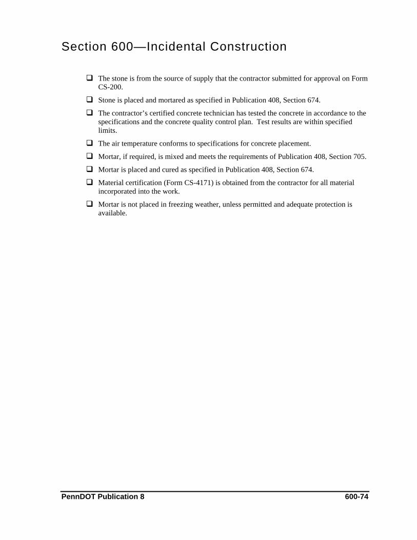
Section 600—Incidental Construction
The stone is from the source of supply that the contractor submitted for approval on Form CS-200.
Stone is placed and mortared as specified in Publication 408, Section 674.
The contractor’s certified concrete technician has tested the concrete in accordance to the specifications and the concrete quality control plan. Test results are within specified limits.
The air temperature conforms to specifications for concrete placement.
Mortar, if required, is mixed and meets the requirements of Publication 408, Section 705.
Mortar is placed and cured as specified in Publication 408, Section 674.
Material certification (Form CS-4171) is obtained from the contractor for all material incorporated into the work.
Mortar is not placed in freezing weather, unless permitted and adequate protection is available.
PennDOT Publication 8 600-74
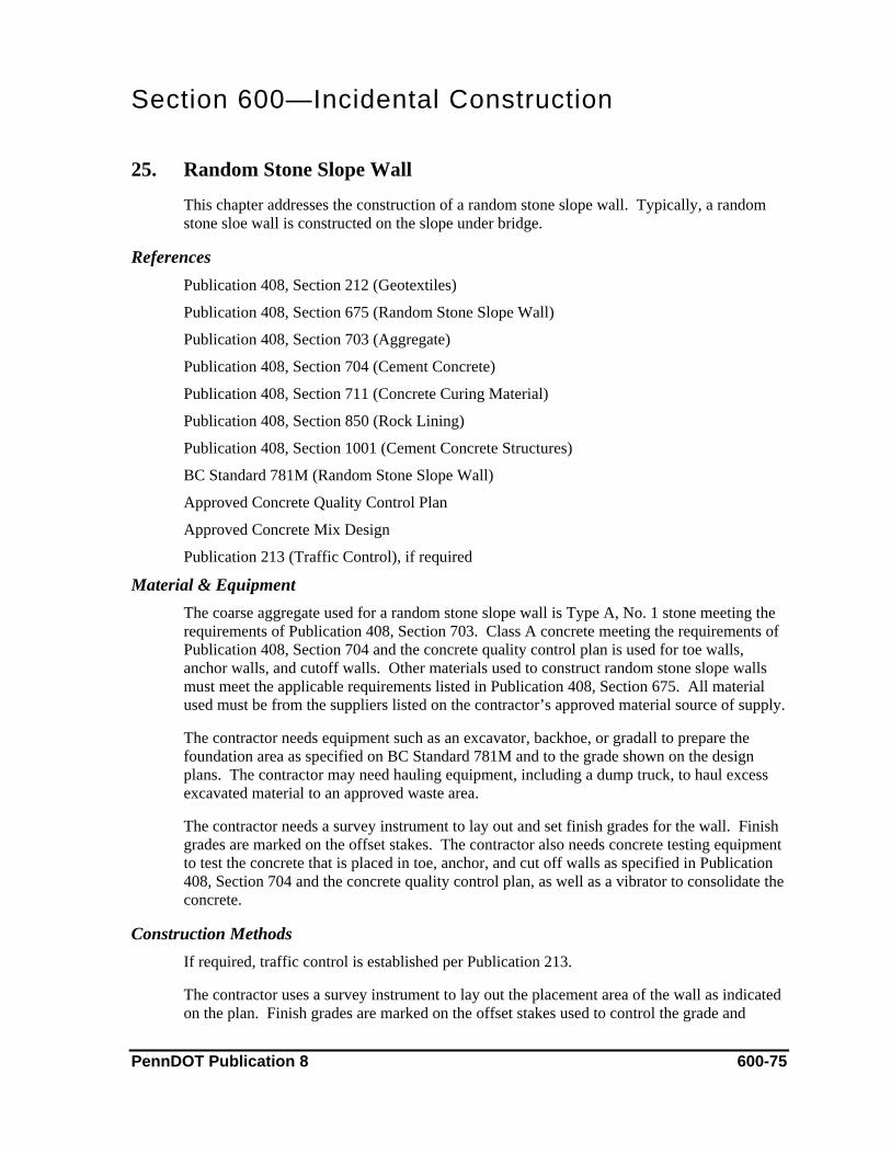
Section 600—Incidental Construction 25. Random Stone Slope Wall
This chapter addresses the construction of a random stone slope wall. Typically, a random stone sloe wall is constructed on the slope under bridge.
References Publication 408, Section 212 (Geotextiles)
Publication 408, Section 675 (Random Stone Slope Wall)
Publication 408, Section 703 (Aggregate)
Publication 408, Section 704 (Cement Concrete)
Publication 408, Section 711 (Concrete Curing Material)
Publication 408, Section 850 (Rock Lining)
Publication 408, Section 1001 (Cement Concrete Structures)
BC Standard 781M (Random Stone Slope Wall)
Approved Concrete Quality Control Plan
Approved Concrete Mix Design
Publication 213 (Traffic Control), if required
Material & Equipment The coarse aggregate used for a random stone slope wall is Type A, No. 1 stone meeting the requirements of Publication 408, Section 703. Class A concrete meeting the requirements of Publication 408, Section 704 and the concrete quality control plan is used for toe walls, anchor walls, and cutoff walls. Other materials used to construct random stone slope walls must meet the applicable requirements listed in Publication 408, Section 675. All material used must be from the suppliers listed on the contractor’s approved material source of supply.
The contractor needs equipment such as an excavator, backhoe, or gradall to prepare the foundation area as specified on BC Standard 781M and to the grade shown on the design plans. The contractor may need hauling equipment, including a dump truck, to haul excess excavated material to an approved waste area.
The contractor needs a survey instrument to lay out and set finish grades for the wall. Finish grades are marked on the offset stakes. The contractor also needs concrete testing equipment to test the concrete that is placed in toe, anchor, and cut off walls as specified in Publication 408, Section 704 and the concrete quality control plan, as well as a vibrator to consolidate the concrete.
Construction Methods If required, traffic control is established per Publication 213.
The contractor uses a survey instrument to lay out the placement area of the wall as indicated on the plan. Finish grades are marked on the offset stakes used to control the grade and
PennDOT Publication 8 600-75
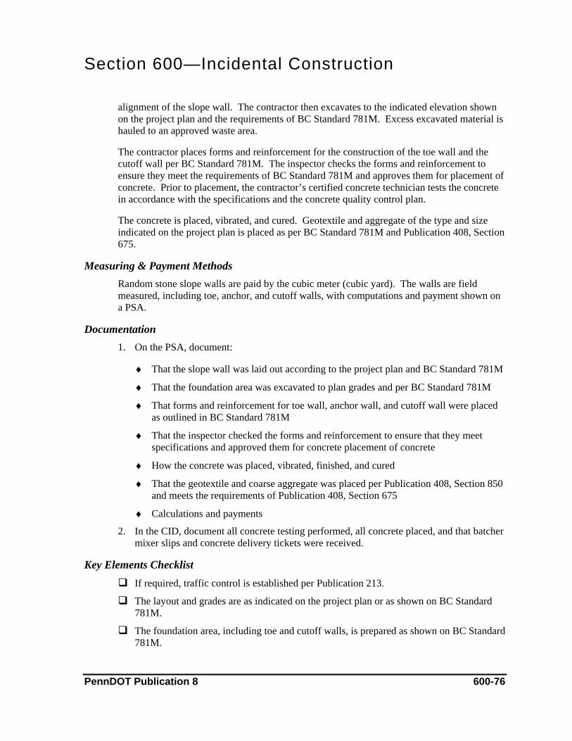
Section 600—Incidental Construction
alignment of the slope wall. The contractor then excavates to the indicated elevation shown on the project plan and the requirements of BC Standard 781M. Excess excavated material is hauled to an approved waste area.
The contractor places forms and reinforcement for the construction of the toe wall and the cutoff wall per BC Standard 781M. The inspector checks the forms and reinforcement to ensure they meet the requirements of BC Standard 781M and approves them for placement of concrete. Prior to placement, the contractor’s certified concrete technician tests the concrete in accordance with the specifications and the concrete quality control plan.
The concrete is placed, vibrated, and cured. Geotextile and aggregate of the type and size indicated on the project plan is placed as per BC Standard 781M and Publication 408, Section 675.
Measuring & Payment Methods Random stone slope walls are paid by the cubic meter (cubic yard). The walls are field measured, including toe, anchor, and cutoff walls, with computations and payment shown on a PSA.
Documentation 1. On the PSA, document:
♦ That the slope wall was laid out according to the project plan and BC Standard 781M
♦ That the foundation area was excavated to plan grades and per BC Standard 781M
♦ That forms and reinforcement for toe wall, anchor wall, and cutoff wall were placed as outlined in BC Standard 781M
♦ That the inspector checked the forms and reinforcement to ensure that they meet specifications and approved them for concrete placement of concrete
♦ How the concrete was placed, vibrated, finished, and cured
♦ That the geotextile and coarse aggregate was placed per Publication 408, Section 850 and meets the requirements of Publication 408, Section 675
♦ Calculations and payments
2. In the CID, document all concrete testing performed, all concrete placed, and that batcher mixer slips and concrete delivery tickets were received.
Key Elements Checklist If required, traffic control is established per Publication 213.
The layout and grades are as indicated on the project plan or as shown on BC Standard 781M.
The foundation area, including toe and cutoff walls, is prepared as shown on BC Standard 781M.
PennDOT Publication 8 600-76
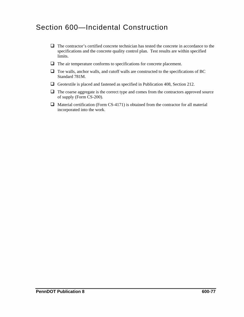
Section 600—Incidental Construction
The contractor’s certified concrete technician has tested the concrete in accordance to the specifications and the concrete quality control plan. Test results are within specified limits.
The air temperature conforms to specifications for concrete placement.
Toe walls, anchor walls, and cutoff walls are constructed to the specifications of BC Standard 781M.
Geotextile is placed and fastened as specified in Publication 408, Section 212.
The coarse aggregate is the correct type and comes from the contractors approved source of supply (Form CS-200).
Material certification (Form CS-4171) is obtained from the contractor for all material incorporated into the work.
PennDOT Publication 8 600-77
Section 600—Incidental Construction 26. Cement Concrete Sidewalks
This chapter addresses the construction of a cement concrete sidewalk on an aggregate bed.
References Publication 408, Section 350 (Subbase)
Publication 408, Section 676 (Cement Concrete Sidewalks)
Publication 408, Section 704 (Cement Concrete)
Publication 408, Section 711 (Concrete Curing Material)
Publication 408, Section 1001 (Cement Concrete Structures)
Approved Concrete Quality Control Plan
Approved Concrete Mix Design
Publication 213 (Traffic Control), if required
Material & Equipment Class A concrete meeting the requirements of Publication 408, Section 704 and the concrete quality control plan is used to construct the sidewalks. The concrete must be produced by an approved supplier and batched from an approved mix design. The coarse aggregate base material used for the subbase must meet the requirements of Publication 408, Section 350. Other materials required to construct the sidewalk must meet the applicable requirements listed in Publication 408, Section 676. All materials used must be from the suppliers listed on the contractor’s approved material source of supply.
The contractor needs small equipment such as a backhoe or gradall to excavate for the sidewalk to the dimensions and grade indicated on the project plan and Publication 408, Section 676. Equipment such as a mechanical tamper or a small walk behind roller is used to compact the foundation area and the coarse aggregate bed as outlined in Publication 408, Section 676. A dump truck or other hauling equipment is used to haul excess excavated material to an approved waste area. The contractor uses a small front-end loader to place the coarse aggregate base material.
The contractor needs a survey instrument to lay out and set grades for the placement of the sidewalk. If matching existing sidewalk, the contractor may stretch a level and string line from existing end to existing end. The contractor also needs concrete testing equipment meeting the requirements of Publication 408, Section 704 to test the concrete placed in the sidewalk, as well as a vibrator to consolidate the concrete.
Construction Methods If required, traffic control is established per Publication 213.
The contractor lays out and excavates the sidewalk location to grade. The foundation area must be smooth, even, and compacted. The contractor then places and compacts the aggregate base.
PennDOT Publication 8 600-78

Section 600—Incidental Construction
Forms are set to line and grade and to the indicated dimensions shown on the project plan and in Publication 408, Section 676. The inspector must approve the base and forms before concrete is placed. The contractor’s certified concrete technician tests the concrete in accordance with the specifications and the concrete quality control plan.
Concrete is then placed, vibrated, finished, and cured. Normally, a broomed finish is applied. After the concrete has cured, the contractor seals the joints. After the forms are removed, the contractor backfills along the sidewalk with acceptable embankment material.
Measuring & Payment Methods Cement concrete sidewalk is paid by the square meter (square yard). After completion, the sidewalk is field measured, with computations and payment shown on a PSA. Areas beyond plan widths cannot be paid unless authorized by the department.
If Class 1A excavation is required to remove unsuitable material below the foundation subgrade elevation, it is paid by the cubic meter (cubic yard). Excavation is also field measured, with computations and payment shown on a PSA.
Documentation 1. On the PSA, document:
♦ The size and location of the sidewalk
♦ That the foundation area and aggregate base was prepared per Publication 408, Section 676
♦ How the contractor compacted the base and that the inspector approved the compaction based on visual non-movement under compaction equipment
♦ That the contractor set the forms to the indicated dimensions and to line and grade
♦ How the contractor placed, vibrated, finished, and cured the concrete
♦ That all joints were constructed and sealed per Publication 408, Section 676
♦ How the sidewalk was backfilled
♦ Calculations and payments
2. In the CID, document all concrete testing performed, all concrete placed, and that batcher mixer slips and concrete delivery tickets were received.
3. Document that that the compaction of the subbase was approved through visual non-movement under compaction equipment on Form TR-478A. If compaction was approved by nuclear density method, use Form TR-4276A.
Key Elements Checklist If required, traffic control is established per Publication 213.
The foundation area is firm, even, and to required grade.
PennDOT Publication 8 600-79

Section 600—Incidental Construction
The aggregate base material is the type indicated and is from the approved supplier listed on the contractors approved source of supply Form CS-200.
The base is compacted properly.
The forms are set to line and grade and to the dimensions indicated.
The contractor’s certified concrete technician has tested the concrete in accordance to the specifications and the concrete quality control plan. Test results are within specified limits.
The air temperature conforms to specifications for concrete placement.
The joints in the sidewalk are laid out per Publication 408, Section 676.
Proper curing measures are undertaken.
The newly-constructed side wall is protected from pedestrian foot traffic by caution tape, safety fence, and other measures.
A material certification form (CS-4171) is obtained from the contractor for all material incorporated into the work.
PennDOT Publication 8 600-80
Section 600—Incidental Construction 27. Selected Material Surfacing
This chapter addresses the finishing and placing of a selected material on a prepared area.
References Publication 408, Section 108 (Character of Workers, Methods, and Equipment)
Publication 408, Section 677 (Selected Material Surfacing)
Publication 408, Section 703 (Aggregates)
Publication 213 (Traffic Control), if required
Material & Equipment The coarse aggregate used is job-specific and must meet the requirements of the type indicated in Publication 408, Section 703. The aggregate must also be furnished by the supplier listed on the contractor’s approved source of supply.
The contractor needs a spreader box to place the aggregate and may use a grader to grade the aggregate. Compaction equipment, meeting the requirements of Publication 408, Section 108, is used to compact the aggregate.
The contractor also needs a survey instrument to lay out and set grades for material placement.
Construction Methods If required, traffic control is established per Publication 213.
The base is prepared as indicated and approved by the inspector. The contractor then spreads the aggregate uniformly on the prepared base, without segregation of coarse and fine material, to the required depth and grade. After the aggregate is placed, it is compacted with a roller meeting the requirements of Publication 408, Section 108. The aggregate is compacted to visual non-movement under compaction equipment and approved by the inspector.
Measuring & Payment Methods Selected material surfacing is paid by the cubic meter (cubic yard) or tonne (ton). If paid by the cubic meter (cubic yard), the material is field measured, with computations and payment made on a PSA. Areas where material was placed beyond plan widths cannot be paid unless authorized by the department.
If the aggregate is paid by the tonne (ton), payment is based on the quantity incorporated into the work as shown on the delivery ticket.
PennDOT Publication 8 600-81

Section 600—Incidental Construction Documentation
1. On the PSA, document:
♦ That the foundation area was prepared as indicated and approved
♦ How the aggregate was placed and that it was placed uniformly and without segregation
♦ That the aggregate was placed to the indicated depth and grade
♦ How the contractor compacted the aggregate and that the aggregate was compacted to visual non-movement under compaction equipment
♦ Station-to-station where the work was performed
♦ Calculations and payments
2. Document that that the compaction of the subbase was approved through visual non-movement under compaction equipment on Form TR-478A. If compaction was approved by nuclear density method, use Form TR-4276A.
Key Elements Checklist If required, traffic control is established per Publication 213.
The foundation area is prepared as indicated.
The aggregate is from the source shown on the contractors approved source of supply.
The aggregate is placed uniformly and without segregation.
The aggregate is compacted properly and documented.
Material certification form (CS-4171) is obtained from the contractor for all material incorporated into the work
PennDOT Publication 8 600-82

Section 600—Incidental Construction 28. Permanent Barricades
This chapter addresses the construction of permanent barricades.
References Publication 408, Section 678 (Permanent Barricades)
Publication 408, Section 704 (Cement Concrete)
RC Standard 63M (Permanent Barricades)
Approved Concrete Quality Control Plan
Approved Concrete Mix Design
Publication 213 (Traffic Control), if required
Material & Equipment The materials used to manufacture the barricade and construct the permanent barricades in the field must meet the applicable requirements outlined in Publication 408, Section 678 and RC Standard 63M. If concrete footings are required, Class A concrete must meet the requirements of Publication 408, Section 704 and the approved concrete quality control plan The concrete must be supplied by an approved concrete batch plant and mixed using an approved concrete mix design. All material used must be from the suppliers listed on the contractor’s approved material source of supply.
The contractor needs a mechanical post driver or a power auger to drive post or auger holes as outlined in Publication 408, Section 678 and RC Standard 63M. In addition, the contractor needs a 1,200 mm (4 feet) level to plumb vertical posts and level horizontal channels. If concrete footings are used, the contractor needs concrete testing equipment meeting the requirements of Publication 408, Section 704.
Construction Methods If required, traffic control is established per Publication 213.
The contractor lays out the locations for the vertical posts. The vertical posts are either driven or a hole is augured and the posts are set in concrete footings that meet the requirements of RC Standard 63M. If concrete footing are constructed, the contractor’s certified concrete technician tests the concrete in accordance to the specifications and the concrete quality control plan. The contractor then erects barricade panels of the type indicated on the plan, per Publication 408, Section 678 and RC Standard 63M.
Measuring & Payment Methods Permanent barricades are paid by the meter (linear foot) to the indicated plan length and field measured to ensure that they meet that plan length. Payment for barriers exceeding plan length is made if authorized by the Department.
PennDOT Publication 8 600-83

Section 600—Incidental Construction Documentation
1. On the PSA, document:
♦ The type of permanent barricade placed and the location
♦ That the barricade meets the requirements of Publication 408, Section 678 and RC Standard
♦ How the contractor placed the vertical post (either by driving the vertical post or by using concrete footings)
♦ Calculations and payments
2. In the CID, document all concrete testing performed, all concrete placed, and that batcher mixer slips and concrete delivery tickets were received.
Key Elements Checklist If required, traffic control is established per Publication 213.
Permanent barricades are from an approved manufacturer shown on the contractors approved material source of supply.
Permanent barricades are erected to the specifications shown in Publication 408, Section 678 and RC Standard 63M.
If concrete footings are constructed, the contractor’s certified concrete technician has tested the concrete in accordance to the specifications and the concrete quality control plan. Test results are within specified limits.
The air temperature conforms to specifications for concrete placement.
Material certification (Form CS-4171) is obtained from the contractor for all material incorporated into the work.
PennDOT Publication 8 600-84
Section 600—Incidental Construction 29. Slab Stabilization
This chapter addresses the filling of voids beneath existing rigid base courses of pavements.
References Publication 408, Section 679 (Slab Stabilization)
RC Standard 26M (Concrete Pavement Rehabilitation)
ASTM AC-939 (Check the Flow of Grout)
Approved Quality Control Plan
Approved Grout Mix Design
Publication 213 (Traffic Control), if required
Material & Equipment The materials required to do this work must meet the applicable requirements listed in Publication 408, Section 679. In addition, the contractor must submit a grout mix design to the department for approval prior to starting work. All material used must be from the suppliers listed on the contractor’s approved source of supply.
The contractor needs a duel-tire single axle vehicle with an 80 kN (18,000 pound) single-axle load to perform a deflection test on the existing pavement, as specified in Publication 408, Section 679 and RC Standard 26M. In addition, a grout plant (meeting the requirements of Publication 408, Section 679) and a water tanker to supply water to the grout pump are needed. The contractor also needs a drill capable of drilling the grout holes through the pavement and base material, such as a core drill and diamond tip core barrels. Vertical movement testing equipment is necessary to measure slab lift.
The contractor needs four gauges capable of detecting slab movement to within 0.03 mm (0.001 inch) for deflection testing as outlined in Publication 408, Section 679.
Construction Methods If required, traffic control is established per Publication 213.
The contractor, along with the inspector, performs a deflection test on joints and cracks as directed. The test is performed per Publication 408, Section 679. The inspector advises the contractor on which joints and cracks require stabilization as determined by the deflection test results.
Grout holes are drilled per RC Standard 26M or as directed. The grout is mixed in the grout plant using the proportions shown on the approved mix design. Gauges meeting the requirements of Publication 408, Section 679 are placed on the existing pavement to monitor lift. The contractor pumps grout into the grout holes, not exceeding a maximum pressure of 1.4 MPa (200 lbs per square inch) or until the grout comes out of another hole. After completion, drilled holes are filled with non-shrink grout. The pavement areas that were
PennDOT Publication 8 600-85
Section 600—Incidental Construction
stabilized are closed to traffic for a minimum of 12 hours. Twenty-four hours after grouting, the stabilized joints or cracks are re-tested.
Measuring & Payment Methods The deflection test is paid each as completed on a PSA. Drill holes (including patching with non-shrink grout) are also paid each. They are field counted and paid on a PSA.
Grout material is paid by kilogram (pound) for the actual amount incorporated into the work. The department will not pay for wasted grout material.
Documentation On the PSA, document:
♦ The field stations of all joints and cracks checked by deflection tests
♦ Inspector’s witness to the deflection tests
♦ Which joints or cracks needed to be stabilized
♦ That the contractor drilled the grout holes per RC Standard 26M
♦ That the grout plant met the requirements of Publication 408, Section 679
♦ That the grout was mixed according to the approved mix design
♦ That the grout was pumped and the pavement was monitored for vertical movement per Publication 408, Section 679
♦ The number of bags of cement used in grouting the holes
♦ That the drill holes were patched with non-shrink grout
♦ That the inspector witnessed the retest of the joints and cracks after 24 hours and the results of the retest
♦ Calculations and payments
Key Elements Checklist If required, traffic control is established per Publication 213.
Deflection tests are performed per Publication 408, Section 679 and RC Standard 26M.
Advise contractor which joints and cracks require stabilization.
Holes are drilled per Publication 408, Section 679 and RC Standard 26M.
Grout is mixed according to the approved mix design.
The flowability of the grout is checked, using the procedures of ASTM CS-939, to ensure it meets the requirements shown on the mix design. This is checked at least twice a day.
When pumping grout, the maximum pressure of 1.4 MPa (200 lbs per square inch) is not exceeded and the existing pavement is monitored for vertical movement.
The grouted area is closed to traffic for a minimum of 12 hours.
PennDOT Publication 8 600-86

Section 600—Incidental Construction
Grouted areas are re-tested after 24 hours and before acceptance.
Material certification (Form CS-4171) is obtained from the contractor for all material incorporated into the work.
PennDOT Publication 8 600-87
Section 600—Incidental Construction 30. Waterproofing
This chapter addresses the furnishing and placing of adhesive preformed membrane waterproofing systems to concrete or other surfaces.
References Publication 408, Section 108 (Character of Workers, Methods, and Equipment)
Publication 408, Section 680 (Waterproofing)
BC Standard 788M (Typical Waterproofing and Expansion Details)
Publication 213 (Traffic Control), if required
Material & Equipment The type of waterproofing system is usually specified on the project plan. If waterproofing system is not specified on the plan, the contractor submits a waterproofing system listed in Bulletin 15 for approval. All material must meet the requirements of the type indicated and the requirements of Publication 408, Section 680. All material used must be from the suppliers listed on the contractor’s approved material source of supply.
The contractor needs a power broom to clean the surface of the pavement before placing the waterproofing on a horizontal surface. If the membrane is to be placed on a bridge deck, the contractor needs a bituminous paver to place the leveling coarse and the bituminous overlay as shown on BC Standard 788M.
Compaction requires a pneumatic tire roller and a tandem steel wheel roller, which must meet the requirements of Publication 408, Section 108. The pneumatic tire roller is used to compact the leveling coarse while the tandem steel wheel roller is used to compact the surface coarse. The contractor also needs a core drill to drill drain holes as shown on BC Standard 788M.
The contractor and the inspector need a thermometer or infrared temperature gun capable of reading temperatures to 204 °C (400F). This device is used to check the temperature of the bituminous material when it arrives on project to ensure it meets the requirements of applicable sections of Publication 408 for the type of material being placed.
Construction Methods If required, traffic control is established per Publication 213.
A trained manufacturer’s technical representative or factory trained licensed installer must be present during every phase of application.
The contractor prepares the surface to be waterproofed per Publication 408, Section 680, BC Standard 788M, and the manufacturer’s recommendations. If required, the surface is conditioned and primed according to the manufacturer’s recommendations.
PennDOT Publication 8 600-88

Section 600—Incidental Construction
The membrane is installed and protected as outlined in Publication 408, Section 680 and BC Standard 788M.
Measuring & Payment Methods Waterproofing systems are paid by the square meter (square yard). These areas are field measured after completion, with computations and payment made on a PSA.
Documentation On the PSA, document:
♦ The type and the location the placed waterproofing system
♦ That the pavement surface was prepared per Publication 408, Section 680, BC Standard 788M, and the manufacturer’s recommendation for the type indicated
♦ That the membrane was placed per Publication 408, Section 680
♦ If the waterproofing is placed on a bridge deck, that the leveling bituminous coarse and the surface bituminous coarse were placed per Publication 408, Section 680 and BC Standard 788M
♦ How the bituminous material was compacted and approved
♦ That a manufacturer’s technical representative was on-site during the waterproofing application or that the system was installed by a factory-trained licensed installer
♦ Calculations and payments
Key Elements Checklist If required, traffic control is established per Publication 213.
The waterproofing system is the one that was specified on the project plan and the one submitted for approval on the contractor’s source of supply form (CS-200).
The surface is prepared per Publication 408, Section 680 and the manufacturer’s recommendations.
If waterproofing is placed on a bridge deck, an approved bituminous mix design is obtained for the leveling and surface coarse.
There is a manufacturer’s representative on-site or the work is completed by a trained, licensed installer.
Material certification (Form CS-4171) is obtained from the contractor for all material incorporated into the work.
PennDOT Publication 8 600-89
Section 600—Incidental Construction 31. Slabjacking
This chapter addresses filling voids beneath existing rigid base courses or pavements and pressure jacking the pavement or base course with cement grout to grade.
References Publication 408, Section 679 (Slab Stabilization)
Publication 408, Section 681 (Slabjacking)
RC Standard 26M (Concrete Pavement Rehabilitation)
ASTM AC-939 (Check the Flow of Grout)
Approved Quality Control Plan
Approved Grout Mix Design
Publication 213 (Traffic Control), if required
Material & Equipment The grout used in slabjacking must meet the requirements of Publication 408, Section 681 and Section 679. The contractor submits a grout mix design meeting the requirements outlined in Publication 408, Sections 679 and 681 for approval prior to performing any work. The grout is mixed as outlined in the approved mix design.
The contractor needs a core drill to drill grout holes through the existing pavement that is to be jacked. Hole patterns are set up per RC Standard 26M or as directed.
A grout plant meeting the requirements of Publication 408, Section 679 is used to mix and pump the jack grout. A water tanker is necessary for supplying water to the grout plant.
The contractor needs a survey instrument to set grades on the offset stakes that will be used for the jacking operation. The existing pavement is jacked to these finish grades.
Construction Methods The contractor submits a grout mix design for approval prior to performing any work. If required, traffic control is established per Publication 213.
The contractor uses a survey instrument to set finish grades, which are marked on offset stakes. A level and string line is stretched between the stakes to control the slabjacking. Drill holes are laid out per RC Standard 26M or as directed.
The contractor drills the holes and mixes the grout in a grout plant according to the approved mix design. The grout is pumped into the holes as required to jack the pavement to the finish grade as outlined in Publication 408, Section 681. After grouting is completed, the grout holes are filled with nonshrink grout as specified in Publication 408, Section 679.
PennDOT Publication 8 600-90
Section 600—Incidental Construction Measuring & Payment Methods
The drill holes are paid each, counted in the field, and paid on a PSA. Grout material is paid according to the number of bags of grout incorporated into the work. No payment is made for wasted grout.
Documentation On the PSA, document:
♦ That the contractor set grades to control the jacking operation
♦ That the grout holes were laid out and drilled per RC Standard 26M or as directed
♦ That the grout was mixed according to the approved mix design and pumped, all within the requirements of Publication 408, Section 681
♦ That the pavement was jacked to the required elevation and did not exceed the limits shown in Publication 408, Section 681
♦ Calculations and payments
Key Elements Checklist If required, traffic control is established per Publication 213.
An approved copy of the grout mix design is obtained.
Holes are drilled per RC Standard 26M or as directed.
Grout is mixed according to the approved mix design.
A flow test on the grout is performed at least twice a day per ASTM AC-939 specifications.
Pavement is jacked to the required elevation.
Material certification (Form CS-4171) is obtained from the contractor for all material incorporated into the work.
PennDOT Publication 8 600-91

Section 600—Incidental Construction 32. Construction Surveying
This chapter addresses construction surveying for roadways, roadway appurtenance, and structures. The work involves preserving vertical and horizontal controls and stationing throughout the construction phase, up to and including final inspection, and to provide the Department inspection force with surveying control points to ensure the quality of construction activities.
References Publication 408, Section 686 (Construction Surveying)
Publication 122M (Department Surveying and Mapping Manual)
Publication 213 (Traffic Control), if required
Material & Equipment The contractor needs surveying instruments, such as an Electronic Distance Measurement (EDM), transit, or level, capable of performing the survey work for the type indicated
Construction Methods If required, traffic control is established per Publication 213.
The contractor performs the construction surveying as outlined in Publication 408, Section 686 to control the project.
Measuring & Payment Methods Construction surveying is paid by lump sum. The payments are made as a percentage of the lump sum, based on the percentage of the total contract amount completed, which is outlined in Publication 408, Section 686.
Documentation On the PSA, document:
♦ The type of surveying performed and what is being surveyed
♦ The type of survey equipment used
♦ The activities that the surveyor performed, such as setting finish grade stakes or setting benchmarks, and why the activities were performed
♦ Calculations and payments
Key Elements Checklist If required, traffic control is established per Publication 213.
The contractor performs the required surveying for the type indicated as outlined in Publication 408, Section 686.
PennDOT Publication 8 600-92

Section 600—Incidental Construction
New benchmark disks are placed as directed.
Survey work is performed by a professional land surveyor or professional engineer.
PennDOT Publication 8 600-93
Section 600—Incidental Construction 33. Built-Up Curb Ramps
This chapter addresses the construction of a built-up curb ramp on a completed surface.
References Publication 408, Section 401 (Flexible Pavements)
Publication 408, Section 460 (Bituminous Tack Coat)
Publication 408, Section 694 (Built-Up Curb Ramps)
RC Standard 67M (Curb Ramps)
Approved Bituminous Mix Design
Publication 213 (Traffic Control), if required
Material & Equipment The bituminous material required is indicated on the project plan and must meet the requirements of the applicable Publication 408 sections. Types of bituminous material used are outlined in Publication 408, Section 694. Bituminous material must be from an approved bituminous batch plant and batched from an approved bituminous mix design.
The contractor needs a distributor meeting the requirements of Publication 408, Section 460 to apply a tack coat to the existing pavement, as well as a dump truck meeting the requirements of Publication 408, Section 401. Equipment such as a mechanical tamper or small roller is used to compact the bituminous material after placement.
The contractor and inspector need a thermometer or infrared temperature gun capable of reading temperatures to 204 °C (400F). These devices are used to check the temperature of the bituminous material when it arrives on the project to ensure that it is within specifications.
Construction Methods If required, traffic control is established per Publication 213.
The contractor lays out the location for the curb ramp according to the project plan and the dimensions shown on RC Standard 67M. The contractor then applies a tack coat meeting the requirements of Publication 408, Section 460 to the existing pavement. Bituminous material of the type indicated is placed per Publication 408, Section 694 and RC Standard 67M. The material is then compacted with a mechanical tamper or small roller.
Measuring & Payment Methods Built-up curb ramps are paid by the tonne (ton) for the amount of bituminous material incorporated into the work, as shown on the bituminous material delivery ticket.
PennDOT Publication 8 600-94

Section 600—Incidental Construction Documentation
1. On the PSA, document:
♦ The location of the curb ramp
♦ That the existing pavement where the ramp was constructed was cleaned and a tack coat applied per Publication 408, Section 460
♦ That the bituminous material met the requirements of Publication 408, Section 694, was from an approved bituminous batch plant, and batched from an approved bituminous mix design
♦ That bituminous material temperatures were taken and that they met the requirements for the type indicated shown in Publication 408, Section 401
♦ That the curb ramp was constructed per RC Standard 67M
♦ How the material was compacted
♦ Calculations and payments
2. On the bituminous material ticket, document the temperature of the material.
Key Elements Checklist If required, traffic control is established per Publication 213.
An approved mix design for the bituminous material is obtained.
The curb ramp is constructed to the dimensions shown on the plan or per RC Standard 67M.
Bituminous material was compacted properly.
Material certification (Form CS-4171) is obtained from the contractor for all material incorporated into the work.
PennDOT Publication 8 600-95
Section 600—Incidental Construction 34. Temporary Impact Attenuating Devices and Reset Temporary
Impact Attenuating Devices This chapter addresses the furnishing, placing, resetting, and removing of temporary impact attenuating devices used for the maintenance and protection of traffic during construction.
References Publication 408, Section 696 (Temporary Impact Attenuating Devices)
Publication 408, Section 697 (Reset Temporary Impact Attenuating Devices)
Publication 2, Project Office Manual, Part C, Section 6 (Impact Attenuators)
Publication 213 (Traffic Control), if required
Material & Equipment The impact attenuator must be supplied by a manufacturer listed in Bulletin 15 and be one of the types shown in Publication 2, Project Office Manual, Part C, Section 6. The contractor submits shop drawings of the attenuator for approval prior to construction to ensure the device meets plan specifications. All material used must be from the suppliers listed on the contractor’s approved material source of supply.
The contractor may need a portable generator to power hand tools used for anchoring the attenuator to the existing pavement, as well as a level to install the attenuator if required by the manufacturer’s specifications.
Construction Methods The contractor submits shop drawings of the temporary attenuators to the Department for approval prior to performing any work.
If required, traffic control is established per Publication 213.
The contractor places the temporary attenuator of the type indicated on the maintenance and protection traffic plan. The attenuator is placed per the manufacturer’s specifications. If the temporary attenuator is reset, the contractor removes the attenuator from one construction area and resets it at another location as indicated within the project limits.
Measuring & Payment Methods Temporary impact attenuating devices are paid each, which includes placement and removal. After placement, the temporary attenuating device is paid on a PSA.
The Department will pay for the repair of temporary attenuating devices by force account. Temporary attenuators that have been reset are paid each, once they have been moved from one location and reset in another location.
PennDOT Publication 8 600-96

Section 600—Incidental Construction Documentation
On the PSA, document: ♦ The type of temporary impact attenuator placed and its location
♦ That the attenuator was placed according to the manufacturer’s specifications for the type indicated on the maintenance and protection of traffic plan
♦ If a temporary attenuator is reset, the reset location and that it was reset according to the manufacturer’s specifications
♦ Calculations and payments
Key Elements Checklist If required, traffic control is established per Publication 213.
A copy of approved shop drawings for the type of temporary impact attenuator installed is obtained.
The temporary impact attenuator is installed according to the manufacturer’s specifications.
Material certification (Form CS-4171) is obtained from the contractor for all material incorporated into the work.
PennDOT Publication 8 600-97
Section 600—Incidental Construction
This Page Left Intentionally Blank
PennDOT Publication 8 600-98

Section 800—Roadside Development
Table of Contents 1. Stockpiling Topsoil or Topsoil Mixture, Topsoil Furnished and Placed, Placing
Stockpiled Topsoil or Topsoil Mixture..................................................................................800-1 2. Seeding and Soil Supplements...............................................................................................800-6 3. Water Course and Slope Erosion Protection..........................................................................800-9 4. Plants, Planting, and Transplanting .....................................................................................800-11 5. Sodding................................................................................................................................800-13 6. Selective Tree Removal and Trimming...............................................................................800-16 7. Temporary Protective Fence for Existing Plant Material ....................................................800-18 8. Erosion and Sedimentation Control Measures/Environmental Compliance .......................800-20
A. Unforeseen Water Pollution Control .........................................................................800-21 B. Rock Lining and Rock Basin .....................................................................................800-23 C. Rock Energy Dissipator and Paved Energy Dissipator..............................................800-26 D. Temporary Slope Pipe Drain .....................................................................................800-30 E. Dewatering Basin.......................................................................................................800-32 F. Rock Barrier...............................................................................................................800-34 G. Concrete Block Revetment Systems..........................................................................800-36 H. Geocell Confinement System ....................................................................................800-39 I. Sedimentation Pond, Sediment Trap, and Sedimentation Structure Cleaning...........800-42 J. Standboxes .................................................................................................................800-46 K. Diversion Ditch..........................................................................................................800-48 L. Silt Barrier Fence .......................................................................................................800-50 M. Sediment Filter Bags..................................................................................................800-52 N. Wetland Mitigation ....................................................................................................800-54 O. Working Around Existing Wetlands..........................................................................800-56 P. Working in Stream Channels .....................................................................................800-58
PennDOT Publication 8 800-i

Section 800—Roadside Development
This Page Left Intentionally Blank
PennDOT Publication 8 800-ii
Section 800—Roadside Development
1. Stockpiling Topsoil or Topsoil Mixture, Topsoil Furnished and Placed, Placing Stockpiled Topsoil or Topsoil Mixture This chapter addresses the process of separating and salvaging topsoil or topsoil mixture encountered during project grading, and depositing it in stockpiles at locations within the right-of-way. The chapter also addresses the furnishing and placing of topsoil from on or off-site stockpiles, preparing indicated areas, and placing topsoil or topsoil mixture on the prepared areas.
References Publication 408, Section 801 (Stockpiling Topsoil or Topsoil Mixture)
Publication 408, Section 802 (Topsoil Furnished or Placed)
Publication 408, Section 803 (Placing Stockpiled Topsoil or Topsoil Mixture)
Publication 408, Section 804 (Seeding and Soil Supplements)
Publication 408, Section 805 (Mulching)
Publication 212 (Official Traffic Control Devices)
Publication 213 (Traffic Control)
Publication 450 (Roadside and Landscape Development Construction Inspection Handbook)
Contract Special Provisions
Erosion and Sedimentation Plan
Approved Traffic Control Plan
Material & Equipment Topsoil consists of friable loamy soil with organic material reasonably free of subsoil, clay, lumps, stones, roots, and branches. Topsoil mixture consists of topsoil combined with organic plant matter, such as crushed or shredded tree branches, stems, bark, leaves, seeds, and roots.
PennDOT Publication 8 800-1
Section 800—Roadside Development
Equipment used in the stockpiling and placement process includes bulldozers, excavators, front-end loaders, payloaders, scrapers, sheepsfoot compactors, and gradalls, as well as hauling equipment, such as on-road and off-road trucks.
Additional equipment, such as a self-powered land clearing shredder, mounted on a bulldozer or loader, is needed for processing topsoil mixtures. The contractor may also used hand tools, such as shovels and rakes, and a tractor with a stone rake.
Construction Methods The contractor is responsible for removing on-site topsoil or topsoil material after clearing and grubbing and prior to other construction.
Stockpiling Topsoil
Once the clearing and grubbing (removal of stumps and roots) is completed and verified by the inspector, the contractor uses a bulldozer or scraper to push the topsoil off of the subsoil and into piles. If the slope is too steep for a bulldozer or scraper, an excavator or gradall may be used for removing topsoil. Care must be taken to avoid mixing the subsoil with the topsoil.
If the topsoil is to be stockpiled off-site, it is loaded into hauling vehicles and delivered to the designated stockpile area.
A stockpile is constructed using a front-end loader or bulldozer. The topsoil must not be compacted or stockpiled in wet or frozen condition. The project erosion and sedimentation plan may require seeding and mulching of the stockpile and/or other erosion and sedimentation control measures. The stockpile area should be within the right-of-way or easement area and not in the way of future construction, unless the contractor has obtained approval for the off-site storage.
Unused topsoil should be leveled and graded uniformly as specified in Publication 408, Section 803, then seeded and mulched as described in Publication 408, Sections 804 and 805.
Stockpiling Topsoil Mixture
During clearing and grubbing, the contractor uses a self-powered land clearing shredder to shred all vegetation as specified in Publication 408, Section 801. A bulldozer is used to push the topsoil and the pulverized vegetation off of the subsoil and into piles to create a topsoil mixture. If the slope is too steep for a bulldozer or scraper, an excavator or gradall may be used to remove the material.
If the topsoil mixture is to be stockpiled off-site, it is loaded into hauling vehicles and delivered to the designated area.
A stockpile is constructed using a front-end loader or bulldozer. The topsoil mixture must not be compacted and must be kept moist. The project erosion and sedimentation plan may require seeding and mulching of the stockpile and/or other erosion and sedimentation control measures. The stockpile area should be within the right-of-way or easement area and not in
PennDOT Publication 8 800-2
Section 800—Roadside Development
the way of future construction, unless the contractor has obtained approval for the off-site storage.
Topsoil Furnished and Placed
After the topsoil is removed from an off-site location, the contractor must recondition the removal area by grading the area, preparing the surface for seeding, and seeding and mulching the area. The contractor prepares the area for topsoil placement as specified in Publication 408, Section 802. Once the site is prepared, the topsoil is placed, spread, and compacted as specified in Publication 408, Section 802
Stockpiled Topsoil Placement and Stockpiled Topsoil Mixture Placement
The contractor should use a method of removing the topsoil from the stockpiles that does not contaminate the topsoil with foreign materials.
The contractor prepares the area for topsoil or topsoil mixture placement as specified in Publication 408, Section 803. Once the site is prepared, the topsoil or topsoil mixture is placed, spread, and compacted as specified in Publication 408, Section 803. Any unused stockpiles of topsoil or topsoil mixture should be uniformly graded, then seeded and mulched.
Measuring & Payment Methods Stockpiling of the topsoil and topsoil mixture is incidental to clearing and grubbing, excavation, and borrow excavation. Payment for topsoil is made by the cubic meter (cubic yard), measured in its final position.
Topsoil furnished and placed is measured in the hauling trucks at the point of placement. The inspector measures and records the inside dimensions of the truck beds to calculate the volume of the truck. The inspector then counts the number of loads hauled and multiplies the total number of loads by the truck volume to arrive at a pay quantity.
Placing stockpiled topsoil or topsoil mixture is paid by the cubic meter (cubic yard). The material is measured in the hauling trucks at the point of placement. The inspector measures and records the inside dimensions of the truck beds to calculate the volume of the truck. The inspector then counts the number of loads hauled and multiplies the total number of loads by the truck volume to arrive at a pay quantity.
Documentation 1. On the PSA, document:
♦ An item description
♦ Actual location of the work
♦ Details of work performed for that day, including materials used, test performed, and equipment used
♦ Payment. If applicable, indicate partial payments, as agreed to by the contractor, and reference any documentation that may have a schedule of payments
PennDOT Publication 8 800-3
Section 800—Roadside Development
2. For placement of topsoil or topsoil mixture, document in the Field Book:
♦ The dimensions of the haul truck beds
♦ Computations for the hauling volume of the trucks
3. Obtain certifications for topsoil furnished and placed
Key Elements Checklist Traffic control, if required, is set up according to the project traffic control plan or per
Publication 213.
At the conclusion of the activities, both daily and at job completion, all traffic patterns are removed and traffic is restored to normal flow, if applicable.
Stockpiling Topsoil
Clearing and grubbing is completed.
As the contractor removes the topsoil from the area, it remains free of contaminants (e.g., rocks, sticks, roots, stumps, and subsoil).
The contractor removes all of the topsoil, taking care not to mix subsoil with the topsoil.
Stockpiles are built away from other materials and on the right-of-way.
Stockpiled topsoil is not compacted.
The stockpiled topsoil is reasonably dry and unfrozen.
Stockpiled topsoil that is not needed for the project is graded.
Seeding and soil supplements are applied as specified in Publication 408, Section 804.
Mulch is applied as directed in Publication 408, Section 805.
All erosion and sedimentation requirements for the stockpiles have been met.
Stockpiling Topsoil Mixture
The contractor adequately shreds all the vegetation within the size limits specified in Publication 408, Section 801 or special provisions.
The topsoil and the shredded vegetation are adequately mixed.
The topsoil mixture is free of contaminants (e.g., rocks, sticks, roots, stumps, and subsoil).
Topsoil mixture stockpiles are not compacted.
The topsoil stockpiles are kept moist but not wet.
Topsoil Furnished and Placed
Topsoil furnished and placed is certified as specified in Publication 408, Section 803.
Topsoil is obtained from outside the right-of-way, where the soil quality has the proven ability to sustain crops.
PennDOT Publication 8 800-4
Section 800—Roadside Development
PennDOT approves topsoil source, depth, and methods of removal.
As the contractor removes the topsoil from the area, is it free of contaminants (e.g., rocks, sticks, roots, stumps, and subsoil).
The area on the project to be covered is graded and soil is loosened to a depth of 50 mm (2 inches).
The contractor reconditions the area of topsoil removal.
The material is reasonably dry and unfrozen.
Place topsoil on the prepared areas and unless otherwise indicated, spread and compact to a 100 mm (4 inches) uniform depth ±40 mm (±1 1/2 inches).
The material is properly compacted.
The compactor is within the weight of 180 kg/m (120 lb per foot) as specified.
Placing Stockpiled Topsoil or Topsoil Mixture
As the contractor removes the topsoil from stockpiles using an acceptable method that does not mix the topsoil with contaminants (e.g., rocks, sticks, roots, stumps, and subsoil).
Soil surfaces are scarified and loosened to a depth of 150 mm (6 inches). Particles of debris and foreign matter 50 mm (2 inches) or larger are removed.
Loosened soil is moistened to optimum moisture content.
Place topsoil on the prepared areas and unless otherwise indicated, spread and compact to a 100 mm (4-inch) uniform depth ±40 mm (±1 1/2 inches).
Place stockpiled mixture to a depth of 150 mm ± 25 mm (6 inches ± 1 inch) measured in place after compaction.
The material is reasonably dry and unfrozen.
The topsoil is free of large stones and other foreign materials detrimental to mowing.
The material is properly compacted.
The compactor is within the weight of 180 kg/m (120 lb/ft) as specified
The contractor returns unused topsoil or topsoil mixture to stockpiles and reconditions the area of topsoil removal.
PennDOT Publication 8 800-5

Section 800—Roadside Development 2. Seeding and Soil Supplements
This chapter addresses seeding and soil supplementation in areas disturbed by earthwork. The work includes seeding various perennial and annual narrow leaf grasses and legumes, then applying soil supplements, including lime, fertilizer, hay or straw mulch, mulch tack, and mulch control netting, to encourage plant growth.
References Publication 408, Section 804 (Seeding and Soil Supplements)
Publication 408, Section 805 (Mulching)
Publication 450 (Roadside and Landscape Development Construction Inspection Handbook)
Contract Drawings
Contract Special Provisions
Material & Equipment Seed used must be appropriately formulated, inspected, and certified by Pennsylvania Department of Agriculture. Soil supplements include fertilizer, pulverized agricultural lime, inoculant for treating legumes, and herbicides conforming to applicable federal and state pesticide regulations. Hay, straw, wood fiber, or pellet mulch is used to maintain moisture and inhibit weed growth. Mulch binder, a fibrous, biodegradable blend of organic matter, is mixed with water and sprayed onto the mulch to hold it in place. Mulch control netting, comprised of plastic or coconut coir yarn, may also be installed to hold the mulch in place.
The contractor uses a hydroseeder to apply the seed mixture and mulch binder and a mulch cannon to apply the mulch. Flatbed trucks are used to haul the material to the work site.
Construction Methods Seeding and Mulching
Final grading and cleanup should be performed as part of excavation. Seed and mulch are not to be applied until area is at final grade, unless the area is to be temporarily seeded. As part of the cleanup, large rocks and debris that would interfere with efficient mowing of the area are removed.
The seeding formula is mixed in the hydroseeder according to table in Publication 408, Section 804. Water is obtained from an acceptable location. The quantity of seed, fertilizer, lime, and inoculant is determined by the size of the area to be seeded. Due to capacity limitations, the contractor may need to mix seed in several small batches.
The seed mixture is applied to prepared areas using the hydroseeder at or above the specified rate. For topsoil areas, the soil is loosened as specified in Publication 408, Section 804 prior to the application of the seeding mixture.
Mulch and mulch binder are applied in a uniform blanket, again using the hydroseeder at or above the specified rate.
PennDOT Publication 8 800-6
Section 800—Roadside Development
Mulch Control Netting
Mulch control netting is installed after the seed mixture, mulch, and mulch binder are applied as specified in Publication 408, Section 805. If coconut coir netting is used, the fabric is stretched over the mulch and anchored with wood stakes along its edges as specified in Publication 408, Section 805.
Measuring & Payment Methods The contractor is paid for the actual pounds of seed used. However, the inspector must calculate the application rate (kilograms per square meter [pounds per square yard]) of seed and mulch to ensure that the minimum seeding and mulching rates in Publication 408, Sections 804 and 805 have been met; also refer to Publication 450.
The seeding application rate is calculated in two-steps. First, the surface area of the seeded locations is determined by measuring the dimensions of the seeded areas and calculating the square meter (square yard) covered. Refer to Publication 408, Section 804 Table A for seed application rates. Second, this area is divided into the number of kilogram (pound) of seed used to cover the area. The result is the seeding application rate. The same process is followed when calculating the mulching and mulch binder rates. For mulch application rates, refer to Publication 408, Section 805.
Mulch control netting is paid in square meter (square yard). The length and width of the area covered is measured and multiplied together to calculate the surface area. Overlaps are only measured once.
Documentation 1. On the PSA, document:
♦ An item description
♦ Actual location of the work performed
♦ Details of work performed for that day
2. In the Field Book, document:
♦ Dimensions of the locations seeded
♦ Computations to calculate the total area seeded
♦ Computations to verify that minimum seed application rates were achieved
♦ Length and width dimensions for mulch control netting and computations for area.
3. On Form M-609 (Roadside Activity Report), document:
♦ List of men and equipment and time worked
♦ List of the work performed, including quantities
♦ Weather and field conditions
4. Obtain material certifications.
PennDOT Publication 8 800-7
Section 800—Roadside Development Key Elements Checklist
The seeding areas are measured and seeding quantities determined.
Do not use seed with a test date older than nine months.
The seed is tested and certified, and is delivered in unopened bags.
The contractor uses the proper quantities of fertilizer, lime, and inoculant and maintains growth to final inspection.
The contractor applies the seeding mixture evenly and at the rate specified in Publication 408, Section 804.
The contractor applies the mulch binder and mulch at the correct rates specified in Publication 408, Section 805
The appropriate mulch is applied for the type of seed used (e.g., straw on Formula B and Formula L seed; hay on remaining formulas).
The mulch control netting is stapled or staked to ensure that the wind will not displace it.
Maintain grass and legume ground cover areas, within the grading limits, until the entire project has been completed. Mow as specified in Publication 408, Section 804.3(k).
Water must be obtained from an acceptable location.
When water is obtained from fire hydrants it must be metered.
PennDOT Publication 8 800-8

Section 800—Roadside Development 3. Water Course and Slope Erosion Protection
This chapter addresses water course and slope erosion protection through the use of rock lining, geotextiles, and synthetic mats.
References Publication 408, Section 806 (Water Course and Slope Erosion Protection)
Publication 408, Section 804 (Seeding and Soil Supplements)
Publication 408, Section 805 (Mulching)
Publication 450 (Roadside and Landscape Development Construction Inspection Handbook)
Contract Special Provisions
Contract Drawings
Material & Equipment Materials used in water course and slope erosion protection include erosion control mulch blankets, erosion control mats, turf reinforcement mats, and anchoring devices, as well as seed, soil supplements, and mulch.
The contractor uses small equipment, including small front-end loaders and excavators, and assorted hand tools, such as spades, picks, anchor pin guns, and hammers. Pick up trucks are usually used for transporting materials.
Construction Methods The area is prepared for mat placement through final grading and dressing of the slope or swale, and removing all rocks and debris. If an erosion control and revegetation mat is used, the appropriate seeding is then applied. The mat is then unrolled onto the protected surface (without deforming its shape) and anchored.
If a turf reinforcement mat is used, both seeding and topsoil must be applied after the mat is placed.
Measuring & Payment Methods Erosion control blankets are paid by the square meter (square yard), based on the surface area of the blanket as calculated by the inspector. The calculated surface area is only for the area covered by the mat and does not include overlap of adjacent mat pieces.
When mat placement requires more than a day, progress payments may be made. Payment is based on the estimated dimensions of the mat placed. Once the placement of the mat is completed, final measurements are taken and the final payment calculated. Estimated payments are then reconciled with the actual payment due.
PennDOT Publication 8 800-9
Section 800—Roadside Development Documentation
1. On the PSA, document:
♦ An item description
♦ Actual location of the work performed
♦ Details of work performed for that day
2. In the Field Book, document:
♦ Dimensions of the locations where the work was performed
♦ Computations for area
3. On Form M-609 (Roadside Activity Report), document any seeding or mulching done in conjunction with the mat installation.
4. Obtain material certifications.
Key Elements Checklist The area requiring mat placement is at final grade and is properly dressed.
If required, seed and mulch are applied prior to mat placement.
The mat is applied without stretching or deforming.
Anchors are driven so that their tops are flush with the ground.
If required, topsoil, seed or mulch is applied to mat after installation.
PennDOT Publication 8 800-10

Section 800—Roadside Development 4. Plants, Planting, and Transplanting
This chapter addresses the furnishing and placement of trees, shrubs, vines, and other woody and herbaceous plants. The work incorporates mulching around trees (placement of shredded bark, gravel, compost, or wood chips) and the preparation of beds for shrubs or herbaceous plants (tilling, weed barrier placement, and mulching).
References Publication 408, Section 805 (Mulching)
Publication 408, Section 808 (Plants, Planting, and Transplanting)
Publication 450 (Roadside and Landscape Development Construction Inspection Handbook)
Contract Special Provisions
Contract Drawings
RC Standard 91M (Bracing and Planting Details)
Material & Equipment Materials for the work include plants (trees, shrubs, herbaceous plants, and woody stemmed plants), wrapping material, fertilizer, and mulch (wood chips, shredded bark, washed gravel, or crushed aggregate), as well as stakes and collar strap attachments to stabilize plantings.
The contractor uses a variety of equipment to haul and place materials, including pick-up trucks, medium-duty stake trucks, all-terrain vehicles, small loaders or backhoes, and tractors with post hole augers or front-end loader. Hand tools, such as picks, shovels, and mattocks, are also used in the work.
Construction Methods Once the inspector has verified the location for each type of plant, the contractor prepares the planting area. This includes digging holes, applying fertilizer or mulch, and installing tree stakes, tree shelters, or tree ties, if required. If small seedlings are planted in an area of existing growth, tree shelters should be installed immediately after planting.
Measuring & Payment Methods Plants are paid as an each item, based on verification of the number of plants for each individual item number and plan location.
Shrub bed preparation is paid as a surface area quantity. The inspector measures the dimensions and calculates the size of the bed in square meter (square yard). Weed barrier mat and mulching are also paid by the square meter (square yard) for planting beds, based on the inspector calculations. If the mat or mulching is placed at a planting pit for an individual plant, payment is incidental to the plant payment.
Initial watering is incidental to plant placement. Maintenance watering is paid at a price per 1,000 liters (1,000 gallons). The water volume used must be easily measurable in either liter (gallon) or cubic meter (cubic foot).
PennDOT Publication 8 800-11

Section 800—Roadside Development Documentation
1. On the PSA, document:
♦ An item description
♦ Actual location of the work performed
♦ Details of work performed for that day
2. In the Field Book, document:
♦ Dimensions of shrub bed preparation
♦ Computations for surface area of shrub bed preparation
3. On Form M-609 (Roadside Activity Report), document:
♦ List of men and equipment and the time worked
♦ List of the work performed, including quantities
♦ Weather and field conditions
4. Obtain material certifications.
Key Elements Checklist The state nursery inspection certificate is provided with each shipment.
The PennDOT District Roadside Development Unit has inspected the plants and completed Form CS-6104 (Plant Material Inspection Report).
The plants are healthy and ready to plant.
The plants are stored properly and protected from the elements.
Planting locations are determined and marked.
The planting site is graded and detrimental materials are removed.
Plant pits and shrub beds are prepared in accordance with the standard drawings and contract provisions.
Care is taken not to damage the plants during the planting process.
An adequate amount of the correct fertilizer is provided during planting.
Plants are adequately watered during planting.
The root systems of the trees are not damaged while placing tree stakes.
Tree stakes and shelters (if required) are installed as the planting is completed.
Tree tie straps are installed properly.
If required, the proper type and amount of mulch (if any) is used.
Plantings are properly maintained during the establishment period.
PennDOT Publication 8 800-12

Section 800—Roadside Development 5. Sodding
This chapter addresses the furnishing, placement, and cultivating of established turf grass (sod) on a designated prepared surface.
References Publication 408, Section 804 (Seeding and Soil Supplements)
Publication 408, Section 809 (Sodding)
Publication 450 (Roadside and Landscape Development Construction Inspection Handbook)
Contract Drawings
Contract Special Provisions
Turfgrass Producers International’s Guideline Specifications to Turfgrass Sodding (current edition)
Material & Equipment The grass comprising the sod should be of two or more Kentucky bluegrass varieties, with no more than 10% of the sod comprising other fine-bladed turf grass species. The sod must be free of weeds, harmful insects, and disease, and be certified by the state Department of Agriculture from which the sod is obtained. The sod should also be relatively free of thatch and well-moistened.
The sod typically comprises segments 300 mm to 600 mm (12 inches to 24 inches) wide and 0.6 m to 1.8 m (2 feet to 6 feet) long. The root system should be approximately 18 mm (¾ inch) thick, with a grass height of no more than 37.5 mm (1½ inches).
Equipment used in the sod bed preparation includes bulldozers, excavators, front-end loaders, and compactors, as well as hauling equipment, such as on-road and off-road trucks.
In placing the sod, the contractor uses equipment such as a small front-end loader, usually of a skid-steer type, and a small roller. Hand tools, including shovels, spades, and hand tampers, are also used.
Construction Methods The contractor must place sod within 36 hours of harvest. If the sod must be stored temporarily, the contractor must protect it from drying out.
In preparing the site, the contractor grades the area to be covered as specified in Publication 408, Section 809. The contractor places the sod by hand; joints should be tight and pieces should not overlap. The sod should be placed in a straight line with the rows placed tightly against each other, with transverse joints broken or staggered.
The sod should be moistened before and after it is placed. Once the sod is completely in place, the top of the sod should be flush with the surrounding finished grade, and lime and fertilizer applied. After the sod is saturated, it should be tamped to close the joints and to
PennDOT Publication 8 800-13
Section 800—Roadside Development
ensure good contact with sod bed. The surface should be tamped smooth, even, and free of bumps and depressions. A roller may be used to complete firming and smoothing of the sod, provided it meets the mass requirements noted in Publication 408, Section 809.3(d).
Measuring & Payment Methods Sodding is paid by the square meter (square yard), based on the measured dimensions of the placed sod. If directed, required watering is paid at a set price per 1,000 liters (1,000 gallons). The water used can be measured using a flow meter or by counting the number of tanks of water of a known volume and multiplying the total loads by the volume of the tank.
If required, mowing (after the initial mowing) is paid in acres. The inspector should measure the dimensions of the area mowed, calculate the area in square meter (square foot) and converted to acres.
Documentation 1. On the PSA, document:
♦ An item description
♦ Actual location of the work performed
♦ Details of work performed for that day
2. In the Field Book, document:
♦ Dimensions of the locations where the work was performed
♦ Computations for area
3. On Form M-609 (Roadside Activity Report), document:
♦ List of men and equipment and the time worked
♦ List of the work performed, including quantities
♦ Weather and field conditions
4. Obtain material certifications.
Key Elements Checklist Sod is placed within 36 hours of being cut.
The cut sod been kept sufficiently moist.
The sod is free of weeds, insects, and diseases.
The height of the grass is less 37.5 mm (1½ inches).
The sod bed is graded and moistened prior to sod placement.
The air and sod temperatures are above freezing.
The joints between sections of sod are tight and transverse joints are staggered.
The sod is moistened after placement and prior to tamping.
PennDOT Publication 8 800-14

Section 800—Roadside Development
The placed sod is tamped to a smooth, even finish.
The sod is properly maintained until the project is accepted.
Sod is not placed when the ground is frozen or when freezing conditions are present, and should be maintained as specified in Publication 408, Section 809.
PennDOT Publication 8 800-15

Section 800—Roadside Development 6. Selective Tree Removal and Trimming
This chapter addresses the removal or trimming of trees and shrubs within or immediately adjacent to the right-of-way. This work also includes treatment of tree injuries and the removal of stumps, debris, and unwanted vegetation.
References Publication 408, Section 810 (Selective Tree Removal and Trimming)
Publication 450 (Roadside and Landscape Development Construction Inspection Handbook)
Contract Drawings
Contract Special Provisions
Material & Equipment Herbicide is the primary material used in this work.
The contractor uses equipment, such as pick-up trucks, bucket trucks, bulldozers, and excavators, and tools, including limb chippers, chainsaws, handsaws, tree trimmers, and stump grinders, in the removal, trimming, and treatment of trees and shrubs.
On-road or off-road trucks are used to haul the debris from the work site.
Construction Methods A Department representative marks the trees and shrubs to be removed; this may involve individual trees or shrubs or sample areas.
The contractor must cut any tree, shrub, or other vegetation to be removed to the ground line or a height specified in Publication 408, Section 810. Trees should be removed in such a way that they will not damage the surrounding vegetation. If removal can not occur without damaging the surrounding vegetation, the tree should be sectioned as it is removed.
The contractor applies herbicide to live stumps the day of cutting and according to manufacturer’s directions. If suckers or sprouts develop on stumps prior to final inspection, the stumps must be retreated with herbicide.
When trimming trees, the contractor removes living and dead branches as specified in Publication 408, Section 810. Work-related injuries to the remaining trees and shrubs are treated according to accepted agricultural practices.
Measuring & Payment Methods Selective tree removal and trimming can be paid as an each item (based on the number of trees removed or trimmed) or by the acre (with dimensions extend to the dripline of the trees removed or trimmed).
Payment can also be made as a lump sum (a contracted, fixed amount for the removal or trimming of the trees). Progress payments can be made based on the dimensions (acreage) of
PennDOT Publication 8 800-16

Section 800—Roadside Development
the work completed. Once the removal or trimming is completed, final measurements are taken and the final payment calculated. Estimated payments are then reconciled with the actual payment due.
Documentation 1. On the PSA, document:
♦ An item description
♦ Actual location of the work performed
♦ Details of work performed for that day
2. In the Field Book, document:
♦ Dimensions of the locations where the work was performed (for units of area and lump sum payments)
♦ Computations for area (for units of area and lump sum payments)
3. A completed Form M-609 (Roadside Activity Report) may be required when payment is made each or by the acre.
4. Obtain material certification.
Key Elements Checklist The trees and vegetation to be removed are marked.
The removed trees and shrubs are cut at the ground line or to a height of not more than 100 mm (4 inches) as directed.
Tree removal does not damage surrounding vegetation.
Tree injuries are appropriately treated.
Brush, limbs, and other debris are disposed of properly.
Check local and DEP regulations for burning and stump disposal
Herbicide is applied to live stumps the day of cutting.
PennDOT Publication 8 800-17
Section 800—Roadside Development 7. Temporary Protective Fence for Existing Plant Material
This chapter addresses the erection of a temporary protective fence for delineating and protecting existing wetlands and areas of plant materials from construction activities.
References Publication 408, Section 811 (Temporary Protective Fence for Existing Plant Material)
Contract Drawings
Contract Special Provisions
Material & Equipment Materials used include standard wooden snow fence, orange safety fence, or other suitably sufficient fencing, along with high-carbon steel posts capable of holding the fencing material, to create a substantial barrier.
The contractor uses equipment such as a pickup truck, sledge hammers, and fence post bars in the construction of the temporary protective fence.
Construction Methods After the contractor and the Inspector-in-Charge determine the location of the fence, posts are driven as needed around the area to be protected. Fencing is attached to the posts with tie-wire.
The contractor must ensure that the fence remains in position and that no one enters the area within the protective fence.
Measuring & Payment Methods Protective fencing is paid in meter (linear foot). The inspector measures the actual length placed and uses that measurement to calculate payment.
Documentation On the PSA, document:
♦ An item description
♦ Actual location of the work performed
♦ Details of work performed for that day
♦ Quantity of fence erected that day (usually measured to the nearest linear foot)
PennDOT Publication 8 800-18
Section 800—Roadside Development Key Elements Checklist
The area to be fenced off requires protection.
The inspector-in-charge and the contractor are in agreement on the position of the fence.
The fence and posts are of acceptable quality.
The completed fence provides a substantial barrier against entry into the protected area.
PennDOT Publication 8 800-19

Section 800—Roadside Development 8. Erosion and Sedimentation Control Measures/Environmental
Compliance This chapter addresses erosion and sedimentation control measures and issues related to environmental compliance.
Erosion and sedimentation occurs naturally; however, the rate at which erosion and sedimentation occurs can be accelerated by construction excavation or soil disturbance, lack of vegetation to protect the soil, or excessive changes in topography. These conditions can readily erode and transport soil into nearby waterways, clogging them with fine sediments known as silt, clay, or colloids. Runoff from bare soil may also contain chemicals and other pollutants that may be washed into waterways.
In an attempt to control sediment pollution, Pennsylvania’s Department of Environmental Protection’s (DEP) Chapter 102 Erosion and Sedimentation Control regulations require that all persons, agencies, and municipalities engaged in earthmoving activities develop, implement, and maintain erosion and sedimentation control measures. DEP also requires that the erosion and sedimentation measures must be set forth in a plan and must be available at the site at all times during construction.
Prior to the start of construction, the contractor submits an erosion and sediment pollution control (E&SPC) plan for approval and acceptance by the Department and other agencies. The plan outlines the schedule for accomplishing temporary and permanent erosion and water pollution abatement. An E&SPC plan is required for all earth disturbances of 4,180 m2 (5,000 square feet) or greater, for earth disturbances in high quality or exceptional value watersheds, or if other DEP permits require it.
In most cases, certain permits must also be obtained. These include an Erosion and Sediment Control Permit (required for projects that disturb between 0.4 and 2.0 ha (1.0 and 5.0 acres) and have a point-source discharge to waters of the commonwealth) and a National Pollution Discharge Elimination System (NPDES) Permit (required for all projects disturbing greater than 2.0 ha [5.0 acres]).
An E&SPC plan is used to identify potential erosion problems and to define effective and economical measures to be used, along with construction operations, to minimize erosion and sedimentation. The E&SPC assists in controlling erosion and sedimentation during the construction process rather than waiting until construction is complete. The plan is also intended to minimize the flow of any sediment and other pollutants generated during the construction project into nearby waterways.
The E&SPC plan should include the following:
• The existing topographic features, including maps and plan drawings, of the project and its surrounding area.
• The characteristics of the earth disturbance activity, and the proposed alteration and erosion and sedimentation pollution control measures and facilities to the project site.
PennDOT Publication 8 800-20
Section 800—Roadside Development
• Detailed instruction in the contract, special provisions and other plans to define the staging, sequencing, and scheduling of operations, as well as the installation and maintenance of such measures and facilities.
• Procedures to ensure that the proper measures for recycling or disposal of materials associated with or from the project site are undertaken.
• A narrative report describing the project and indicating the purpose and the engineering assumptions and supporting calculations for control measures and facilities.
A number of control measures are discussed in this chapter. These include rock linings, rock basins, rock energy dissipaters, paved energy dissipaters, geocell confinement systems, silt barrier fencing, sedimentation ponds, diversion ditches, standboxes, and other measures.
During a construction project, everyone’s goal is to control erosion and the resulting pollution of the waters of the commonwealth. This can be partially achieved by thoughtful planning and scheduling of construction earthmoving activities. Site inspections are conducted to assure that measures are properly implemented, controls are installed, and sequences are followed.
A. Unforeseen Water Pollution Control This subchapter addresses the construction or installation of temporary or permanent control measures, as ordered during the contract life, to control unforeseen pollution of surface and groundwater resources.
References Publication 408, Section 845 (Unforeseen Water Pollution Control)
Construction Plans
RC Standard 70M (Erosion and Sedimentation Pollution Control)
Erosion and Sediment Pollution Control Plans
Material & Equipment Erosion and sediment pollution control devices-and the equipment to install the devices are shown on the standard drawings. Water pollution control measures and devices are used as directed by the Inspector-in-Charge. These devices may include erosion control blankets and mats, geotextile fabrics, silt barrier fence, inlet protection, and straw bales.
Construction Methods The contractor is required to provide water pollution control measures to prevent or abate unforeseen pollution of surface and groundwater resources. It is also the contractor’s responsibility to install, maintain, and monitor all necessary erosion and sediment pollution control measures and facilities during the construction project.
If directed, contractor must place pollution control measures outside of the authorized construction area right-of-way.
PennDOT Publication 8 800-21
Section 800—Roadside Development Measuring & Payment Methods
(a) Contract Items. The Department will pay for performance of work, identified as having similar items listed in the contract, at the contract unit price.
(b) Non-Contract Items. The Department will pay for items of work not identified in the contract as follows:
1. Negotiated Price. At price agreed upon with the Department before before performing the work. If applicable, agreement is also required with FHWA.
2. Force Account Basis. Section 110.03(d).
Documentation 1. On the PSA, document:
♦ Item description and location of work performed
♦ Labor and equipment used
♦ Brief description of the work performed
♦ Description of the existing type of water pollution and if control is being achieved as best possible
2. Obtain material certifications.
Key Elements Checklist Construction plans and E&SPC plans are reviewed.
Water pollution control methods are in place prior to earthwork operations.
If the work includes any permits or additional approved plans by other agencies; copies are on file.
Interferences with free discharge of any waterways during construction are remediated.
Inlets, ditches, or any type of drainage systems are protected from sediments.
Excavated material is not placed in swales or ditches.
Streambeds are not used as a roadway between operation sites.
Water pollution control devices are inspected regularly to ensure that the contractor is maintaining and continuing controls.
All water originating outside of the construction project is kept separate from that originating within the project.
PennDOT Publication 8 800-22

Section 800—Roadside Development B. Rock Lining and Rock Basin
This subchapter addresses the construction of an indicated class rock lining (a measure to prevent excessive soil erosion under the rock from an existing flow channel) and the construction of a rock basin of the size and type indicated.
References Publication 408, Section 735 (Geotextiles)
Publication 408, Section 850 (Rock Lining)
Publication 408, Section 853 (Rock Basin)
RC Standard 70M (Erosion and Sedimentation Pollution Control)
Construction Plans
Erosion and Sediment Pollution Control Plans
Approved Quality Control Plan
Material & Equipment The material and equipment needed to construct the rock lining includes rocks of a specified size, Class 2 geotextile. Material for the rock basin includes Class R-7 rock (as indicated) Class 2, Type A geotextile (as specified), and grout.
In constructing the rock lining or the rock basin, the contractor uses a loader, backhoe, excavation equipment, dump trucks, mixer trucks, and grout mixer as well as various hand tools. The contractor also needs concrete testing equipment to test the air content in the grout.
Construction Methods The contractor prepares the area for the rock lining; work may include backfilling or excavation to remove unsuitable material and large stones from the protected area. The area is graded to a relatively smooth condition and constructed with a 2:1 slope, per RC Standard 70M, unless otherwise specified.
The contractor places Class 2 geotextile, as directed. Specified rock is then placed (according to the design) onto the geotextile material in an even distribution pattern minimizing voids using equipment such as a gradall, backhoe, or a track excavator. Rocks may be rearranged after placement to produce uniform distribution.
Rock basins must be constructed per contract drawings and specifications. Prior to rock basin construction, the contractor prepares the area; work may include clearing or grubbing, excavation for removal of unsuitable material or large stones, or backfilling. The area is then graded to a relatively smooth condition. The contractor installs geotextile in areas with ground contact, as specified, then evenly distributes specified rock size (according to the design) onto the geotextile with a minimum of voids. The rock is placed in a manner that will not damage the geotextile. A full course thickness of rock is placed in one operation to
PennDOT Publication 8 800-23
Section 800—Roadside Development
prevent segregation. Rocks may be rearranged after placement to produce uniform distribution.
The contractor’s certified technician tests the grout for entrained air as specified in Publication 408, Section 853. The rock is then saturated with water and voids between rock pieces are filled as directed with approved grout. The surface is swept with a stiff broom.
If the work is performed during hot weather, saturated burlap is used to protect grouted rock and keep it moist for at least three days after grouting.
Measuring & Payment Methods In rock lining, the rock is paid by the square or cubic meter (square or cubic yard). Geotextile is paid by the square meter (square yard) and excavation is paid by the cubic meter (cubic yard) for class indicated.
Rock basin construction is paid as an each item, complete in-place.
Documentation 1. On the PSA, document:
♦ Item description and location of work performed
♦ Labor and equipment used on the operation
♦ Preparation work performed by the contractor
♦ Description of the work performed
♦ Quantity of unsuitable material excavated and location of disposal
♦ Quantity and type of rock received and verified from collected from delivery tickets
♦ Quantity of geotextile material used
♦ Reference to item folders for material certifications received
♦ Reference to the Field Book with recorded information
♦ Any deviation from the plans, such as excessive erosion
♦ Measurements and calculations for materials and excavation
♦ Payments
2. Ensure that concrete is properly documented:
♦ In the CID, document the required information for each load of grout and the results of testing
♦ If the grout is supplied from a ready-mix plant and not mixed on-site, obtain delivery tickets for each load of concrete as it arrives on the project
♦ Prior to concrete placement, obtain an approved quality control plan and approved mix designs
PennDOT Publication 8 800-24
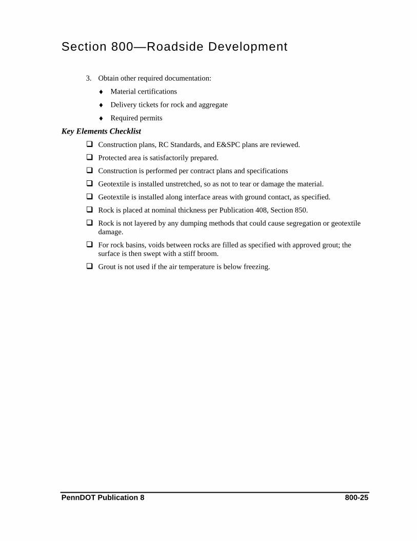
Section 800—Roadside Development
3. Obtain other required documentation:
♦ Material certifications
♦ Delivery tickets for rock and aggregate
♦ Required permits
Key Elements Checklist Construction plans, RC Standards, and E&SPC plans are reviewed.
Protected area is satisfactorily prepared.
Construction is performed per contract plans and specifications
Geotextile is installed unstretched, so as not to tear or damage the material.
Geotextile is installed along interface areas with ground contact, as specified.
Rock is placed at nominal thickness per Publication 408, Section 850.
Rock is not layered by any dumping methods that could cause segregation or geotextile damage.
For rock basins, voids between rocks are filled as specified with approved grout; the surface is then swept with a stiff broom.
Grout is not used if the air temperature is below freezing.
PennDOT Publication 8 800-25
Section 800—Roadside Development C. Rock Energy Dissipator and Paved Energy Dissipator
This subchapter addresses the construction of a rock energy dissipator of the class indicated, to dissipate energy and control erosion at pipe outlets with high water discharge velocity. It also addresses the construction of a paved energy dissipator consisting of a reinforced cement concrete channel embedded with stones or solid pre-cast blocks.
References Publication 408, Section 851 (Rock Energy Dissipator)
Publication 408, Section 852 (Paved Energy Dissipator)
Publication 408, Section 1001 (Cement Concrete Structures)
RC Standard 70M (Erosion and Sedimentation Pollution Control)
Construction Plans
Erosion and Sedimentation Control Plans
Approved Quality Control Plan
Approved Concrete Mix Design
Material & Equipment Material for the rock energy dissipator includes rock, Class 2 geotextile, and grout, all as specified. In constructing the rock energy dissipator, the contractor uses equipment such as loaders, backhoes, excavators, dump trucks, concrete testing equipment, and various hand tools.
Materials for the paved energy dissipator include Class A cement concrete, steel-welded wire fabric reinforcements, joint sealer, pre-molded expansion joint filler, bituminous paper, and pre-cast concrete blocks or stones of acceptable quality, if required. In constructing the paved energy dissipator, the contractor uses excavation and compaction equipment, a concrete mixer and or concrete delivery truck, concrete testing equipment, vibrators, and various hand and finishing tools.
Construction Methods The rock energy dissipator and the paved energy dissipator must be constructed per contract plans, standards, and specifications.
The contractor prepares the area for the rock energy dissipator; this work may include clearing or grubbing, excavation to remove unsuitable material or large stones, or backfilling of the area to be protected. The area is then graded to a relatively smooth condition.
Geotextile is installed in place along interface areas with ground contact, as specified, and in a loose and unstretched condition. Specified rock size, as shown on construction plans and drawings, is evenly distributed onto the geotextile with a minimum number of voids. The rock is also placed in a manner that will not damage the geotextile. A full-course thickness of
PennDOT Publication 8 800-26
Section 800—Roadside Development
rock should be placed in one operation in a manner that prevents segregation. Rocks may be rearranged after placement to produce uniform distribution.
The contractor’s certified technician tests the grout for entrained air as specified in Publication 408, Section 851. Rocks are then saturated with water, voids between rock pieces filled as directed with approved grout, and the surface swept with a stiff broom. Saturated burlap is used to protect the grouted rock during hot weather and must be kept moist for at least three days after grouting.
Prior to constructing the paved energy dissipator, the contractor excavates the area to the required paving depth and removes and replaces any unsuitable material below the bottom of the paving. The area is then compacted to a firm, even surface to provide an acceptable foundation.
Before the concrete is placed, the contractor’s certified technician tests all concrete according to the approved quality control plan. Concrete cylinders must also be molded for compressive strength tests, if required. The concrete is placed and finished as specified in Publication 408, Section 1001, with reinforcement mesh set in the concrete during placement. The contractor must pave and construct joints as specified in Publication 408, Section 852.
Measuring & Payment Methods Construction of a rock energy dissipator is paid as an each item, complete in-place. Construction of a paved energy dissipator is paid by the cubic meter (cubic yard).
Excavation for the removal of unsuitable material is also paid by the cubic meter (cubic yard), at the same rate as the class of excavation for the ditch or channel above the paving. These are field measured and paid on a PSA.
Documentation 1. On the PSA, document:
♦ An item description and location of work being performed
♦ Labor and equipment used on the operation
♦ Description of work performed during operation
♦ That materials used are per specifications
♦ Quantity of geotextile used;
♦ Quantity and type of rock received and verified from delivery tickets
♦ Reference to the Filed Book with recorded information;
♦ Any deviation from plans
♦ Measurements and calculations for materials used, if required
♦ Payment
PennDOT Publication 8 800-27

Section 800—Roadside Development
2. Ensure that concrete is properly documented:
♦ In the CID, document the required information for each load of concrete and the results of testing
♦ Delivery tickets for each load of concrete as it arrives on the project
♦ Prior to concrete placement, obtain an approved quality control plan and approved mix designs
3. Obtain other required documentation:
♦ Material certifications
♦ Delivery tickets for rock and aggregate
♦ Required permits
Key Elements Checklist Rock Energy Dissipator
RC standards and erosion and sedimentation control plans are reviewed.
Construction is performed per contract plans and specifications.
Geotextile is placed in a loose and unstretched condition.
Geotextile is not damaged during rock placement.
Voids are minimized during rock placement.
A full course thickness of rock is placed in one operation in a manner to prevent segregation.
Rock is not placed in layers, by dumping into chutes, or in any manner likely to cause segregation.
Grout is tested for entrained air as specified.
Voids between rock are filled as specified, with approved grout; the surface is then swept with a stiff broom.
Grout is not placed if the air temperature is below freezing.
Grouted rock is protected during hot weather using saturated burlap and kept moist for at least three days.
Paved Energy Dissipator
Construction is performed per contract plans and specifications.
The foundation area is prepared per plans.
The inspector contacted the concrete plant and has given the release for concrete.
Concrete testing for temperature, air, and slump is witnessed according to the approved quality control plan.
PennDOT Publication 8 800-28
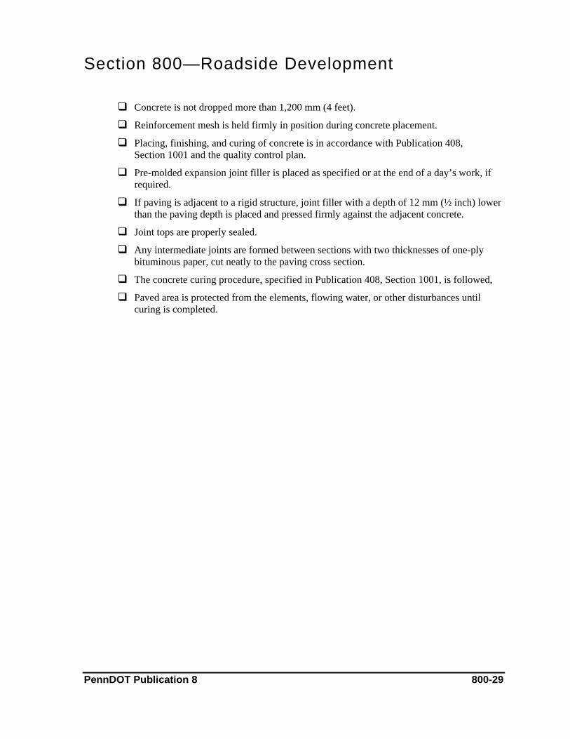
Section 800—Roadside Development
Concrete is not dropped more than 1,200 mm (4 feet).
Reinforcement mesh is held firmly in position during concrete placement.
Placing, finishing, and curing of concrete is in accordance with Publication 408, Section 1001 and the quality control plan.
Pre-molded expansion joint filler is placed as specified or at the end of a day’s work, if required.
If paving is adjacent to a rigid structure, joint filler with a depth of 12 mm (½ inch) lower than the paving depth is placed and pressed firmly against the adjacent concrete.
Joint tops are properly sealed.
Any intermediate joints are formed between sections with two thicknesses of one-ply bituminous paper, cut neatly to the paving cross section.
The concrete curing procedure, specified in Publication 408, Section 1001, is followed,
Paved area is protected from the elements, flowing water, or other disturbances until curing is completed.
PennDOT Publication 8 800-29

Section 800—Roadside Development D. Temporary Slope Pipe Drain
This subchapter addresses the installation of a temporary slope pipe drain, used to temporarily drain water from the work area until permanent drainage is installed.
References Publication 408, Section 601 (Pipe Culverts)
Publication 408, Section 616 (End Sections and Slope Pipe Fittings)
Publication 408, Section 735 (Geotextiles)
Publication 408, Section 854 (Temporary Slope Pipe Drain)
RC Standard 70M (Erosion and Sedimentation Pollution Control)
Construction Plans
Erosion and Sediment Pollution Control Plans
Material & Equipment Material used for the work includes a metal end section, pipe (inlet and outlet), fill slope pipe, and Class 2 geotextile. The contractor uses excavation and compaction equipment in installing the slope pipe drain.
Construction Methods The contractor constructs a berm of compacted embankment material along the work area, if required. The metal end section is installed at the inlet end to channel the flow of water into temporary pipe. The pipe is installed and anchored to slope at the length required to reach a suitable discharge area.
Geotextile is placed at the discharge area of pipe and secured in place. Rock may also be placed, if necessary, to prevent erosion.
Measuring & Payment Methods Temporary slope pipe drains are paid as an each item, complete in-place.
Documentation 1. On the PSA, document:
♦ An item description and location of work performed
♦ Labor and equipment used on the operation
♦ Brief description of the work performed during operation
♦ Quantity of materials used
♦ Reference to plans or drawings
♦ Reference to the Field Book with recorded information
PennDOT Publication 8 800-30
Section 800—Roadside Development
♦ Measurements and calculations
♦ Payments
2. Obtain material certifications.
Key Elements Checklist Drawings and plans are reviewed.
Geotextile is not damaged during placement.
Metal end sections are installed per specifications.
Pipe allows proper water flow.
Pipe connections are tightly secured.
Erosion is minimized at the discharge area.
Frequent inspections for accumulated sediment at the inlet or any damage to pipe are conducted.
PennDOT Publication 8 800-31
Section 800—Roadside Development E. Dewatering Basin
This subchapter addresses the construction of a basin for removing sediment from pumped water.
References Publication 408, Section 206 (Embankment)
Publication 408, Section 703 (Aggregate)
Publication 408, Section 804 (Seeding and Soil Supplements)
Publication 408, Section 805 (Mulching)
Publication 408, Section 850 (Rock Lining)
Publication 408, Section 855 (Dewatering Basin)
RC Standard 70M (Erosion and Sedimentation Pollution Control)
Construction Plans
Erosion and Sedimentation Control Plans
Material & Equipment Material used includes Class R-3 rock, No. 67 aggregate, embankment material (if required), seeding and soil supplements (if specified), and mulch (if specified). The contractor uses excavation and compaction equipment in constructing the dewatering basin.
Construction Methods The dewatering basin must be constructed per drawings and RC Standards. The process may include clearing and grubbing of the area, excavation; and embankment formation to the required dimensions.
Rock and aggregate is placed at the outlet end as indicated on plans. Seeding, soil supplements, and mulch are applied as specified.
Measuring & Payment Methods Construction of dewatering basins is paid as an each item, complete in-place and includes removal.
Documentation 1. On the PSA, document:
♦ An item description and location of work performed
♦ Labor and equipment used on the operation
♦ Description of the work performed during operation
♦ That the work is performed per drawings and specifications
PennDOT Publication 8 800-32
Section 800—Roadside Development
♦ Quantity and type of rock and aggregate received and verified from delivery tickets
♦ Quantity and type of seeding, soil supplements, and mulch
♦ Reference to field books with necessary recorded information
♦ Any deviation from plans
♦ Measurements and calculations for materials
♦ Payments
2. On Form M-609 (Roadside Activity Report), document (for seed and mulch):
♦ List of men and equipment and time worked
♦ List of the work performed, including quantities
♦ Weather and field conditions
3. Obtain other required documentation:
♦ Material certifications
♦ Delivery ticks for items such as tock, aggregate, and seedlings
Key Elements Checklist Construction plans, RC standards, and erosion and sedimentation control plans are
reviewed.
Construction is according to plans.
Necessary permits are obtained and copies are on file.
Aggregate is placed at nominal thickness, as indicated.
Pump discharge does not cause erosion at outlet.
Sediment particles are removed by dewatering system.
When the dewatering is no longer required, or if otherwise directed, the site is reconditioned and area restored as specified.
PennDOT Publication 8 800-33

Section 800—Roadside Development F. Rock Barrier
This subchapter addresses the construction of a rock barrier, including a coarse aggregate filter blanket. This may be used to remove sediment from runoff water or to control sediment originating in a channel.
References Publication 408, Section 703 (Aggregates)
Publication 408, Section 850 (Rock)
Publication 408, Section 856 (Rock Barrier)
RC Standard 70M (Erosion and Sedimentation Pollution Control)
Construction Plans
Erosion and Sedimentation Control Plans
Material & Equipment Material for the work includes Class R-7 rock, No. 57 and No. 67 coarse aggregate (as indicated), and Class 3, Type B geotextile, if specified. In constructing the rock barrier, the contractor uses a bulldozer, loader, backhoe, excavation equipment, and a variety of hand tools.
Construction Methods The rock barrier must be constructed as shown on construction plans and drawings.
The contractor determines the required length of the ditch or depression slope. If geotextile is required, a trench is excavated on the upstream side of the rock barrier.
The rock barrier is constructed to be equal in height to one-half the total depth of the channel. Rock pieces are evenly distributed with minimum voids. Coarse aggregate is used to construct a filter blanket as shown on construction plans and drawings. The top of the rock barrier is then tapered to the depth specified, with a depression in the center of flowline.
Measuring & Payment Methods Rock is paid by the square meter (square yard) or cubic meter (cubic yard). Coarse aggregate is paid by the cubic meter (cubic yard). Payment for geotextile is as specified in the contract documents.
Documentation 1. On the PSA, document:
♦ An item description and location of work performed
♦ Labor and equipment used on the operation
♦ Description of the work performed during operation
PennDOT Publication 8 800-34

Section 800—Roadside Development
♦ That materials used are per specifications
♦ Quantity and type of rock and aggregate received and verified from delivery tickets
♦ Quantity of geotextile used
♦ Reference to Field Book with recorded information
♦ Any deviation from plans
♦ Measurements and calculations for materials used
♦ Payments
2. Obtain other required documentation:
♦ Material certifications
♦ Delivery tickets for rock and aggregate
♦ Required permits
Key Elements Checklist Construction plans, RC standards, and erosion and sedimentation control plans are
reviewed.
Construction is performed per contract plans and specifications.
Trench is excavated per plans for installing geotextile.
Geotextile is placed as shown on construction plans and drawings.
During rock placement, there are minimum voids.
Rock barrier is constructed to be equal in height to one-half the total depth of the channel, with a depression of 150 mm to 300 mm (6 inches to 12 inches) in the center of the flowline.
Inspections are frequently conducted to determine if aggregate must be replaced or if any repairs are necessary.
Contractor removes any accumulated sediment per specifications.
PennDOT Publication 8 800-35

Section 800—Roadside Development G. Concrete Block Revetment Systems
This subchapter addresses the construction of an articulating system of interlock pre-cast concrete blocks or cable-connected pre-cast concrete block mats for erosion protection of slopes and channels.
References Publication 408, Section 703 (Aggregate)
Publication 408, Section 713 (Masonry Units)
Publication 408, Section 714 (Precast Concrete Products)
Publication 408, Section 802 (Topsoil Furnished and Placed)
Publication 408, Section 804 (Seeding and Soil Supplements)
Publication 408, Section 805 (Mulching)
Publication 408, Section 806 (Water Course and Slope Erosion Protection)
Publication 408, Section 857 (Concrete Block Revetment Systems)
Construction Plans
Erosion and Sedimentation Control Plans
Material & Equipment Materials used in the work include pre-cast concrete blocks, stainless steel cable (used for connected block systems), geotextile, soil anchors, backfill, and aggregate. If directed, topsoil, seeding and soil supplements, mulch, and an erosion control mulch blanket are also used.
In constructing the concrete block revetment system, the contractor uses a backhoe, bulldozer, and compaction equipment.
Construction Methods The contractor prepares and excavates the area by removing obstructions, including tree roots, large stones, or debris, to a depth specified below subgrade. The slope area is graded to provide a smooth surface. Any voids or soft areas are backfilled with suitable material and compacted. Fine grading is performed in areas as needed before placing geotextile.
Geotextile is placed on the prepared area, as specified, and is anchored or secured by acceptable methods. Concrete blocks are placed over the geotextile according to the manufacturer’s instructions and contract plans and specifications.
Cable-connected concrete block systems are secured to the slope with soil anchors as indicated. After the blocks are placed, open areas of the block are backfilled with topsoil or aggregate, to the top of blocks, as indicated. Backfilling must be completed within seven days of placing geotextile.
PennDOT Publication 8 800-36
Section 800—Roadside Development Measuring & Payment Methods
Concrete block revetment systems are paid by the square meter (square yard), as field measured. If aggregate backfill if used, payment is incidental to the work. All other materials are paid as specified in the applicable Publication 408 sections.
Documentation 1. On the PSA, document:
♦ An item description and location of work performed
♦ Labor and equipment used on the operation
♦ Description of the work performed during operation
♦ That work being performed is per contract plans and specifications
♦ Quantity of geotextile material used
♦ Reference to item folders for material certifications received
♦ Reference to Field Book with recorded information
♦ Any deviation from plans (such as excessive erosion)
♦ Measurements and calculations for materials used
♦ Payments
2. On Form M-609 (Roadside Activity Report), document (for seed and mulch):
♦ List of men and equipment and time worked
♦ List of the work performed, including quantities
♦ Weather and field conditions
3. Obtain other required documentation:
♦ Material certifications.
♦ Delivery tickets for aggregate, if required
♦ Required permits
Key Elements Checklist Construction and erosion and sedimentation control plans are reviewed.
Work is performed per contract plans and specifications.
Area is satisfactorily prepared prior to placing geotextile.
Geotextile is placed in an unstretched condition, so as not to tear or damage the material.
Geotextile is securely anchored.
PennDOT Publication 8 800-37

Section 800—Roadside Development
Concrete block systems are properly placed and securely anchored in slope per plans and specifications.
Backfill material is placed as indicated.
Backfilling is completed within seven days of placing geotextile.
If aggregate is used as backfill, the size of aggregate is per manufacturer’s recommendations and contract plans.
Unsound or damaged blocks are not used.
Application of seeding, soil supplements, and mulch is per specifications.
PennDOT Publication 8 800-38

Section 800—Roadside Development H. Geocell Confinement System
This subchapter addresses furnishing and maintaining a geocell confinement system for slope erosion protection.
References Publication 408, Section 212 (Geotextiles)
Publication 408, Section 737 (Geocell)
Publication 408, Section 735 (Geotextiles)
Publication 408, Section 804 (Seeding and Soil Supplements)
Publication 408, Section 805 (Mulching)
Publication 408, Section 858 (Geocell Confinement System)
Construction Plans
Erosion and Sedimentation Control Plans
Material & Equipment Materials for the work include stakes, fasteners, No. 2A or 67 coarse aggregate (as indicated), Class 2, Type B, non-woven geotextile. In addition, topsoil, seeding, soil supplements, and mulch are also used.
In constructing geocell confinement system, the contractor uses a bulldozer, loader, dump truck, and compaction equipment.
Construction Methods The contractor prepares the area by clearing large rocks, vegetation, and debris, then grading the surface smooth. Geotextile is then placed on prepared area, in a loose unstretched condition, as specified. The geotextile is anchored or secured by an acceptable methods, such as with securing pins or aggregate.
Geocell confinement sections are placed on the geotextile by expanding the material with its longer dimensions parallel to slope direction, up and down. Sections should be flush or slightly lower than adjacent final grade and anchored in place, as indicated.
Backfill is placed flush with the top of cells and compacted. Seeding and soil supplements and mulch are then applied as indicated.
Measuring & Payment Methods Geotextile confinement systems are paid by the square meter (square yard). The unit price includes backfill as indicated. Geotextile is paid by the square meter (square yard).
Seeding and soil supplements are paid as indicated in Publication 408, Section 804, while mulch is paid according to Publication 408, Section 805.
PennDOT Publication 8 800-39
Section 800—Roadside Development Documentation
1. On the PSA, document:
♦ An item description and location of work performed
♦ Labor and equipment used on the operation
♦ Description of the work performed during operation
♦ That the work is performed per drawings and plans
♦ Quantity of geotextile used
♦ Quantity of geocell material used
♦ Reference to item folders for material certifications received
♦ Reference to any field books with recorded information
♦ Any deviation from plans
♦ Measurements and calculations for materials used
♦ Payments
2. On Form M-609 (Roadside Activity Report), document (for seed and mulch):
♦ List of men and equipment and time worked
♦ List of the work performed, including quantities
♦ Weather and field conditions
3. Obtain other required documentation:
♦ Material certifications.
♦ Delivery tickets for aggregate, if required
♦ Required permits
Key Elements Checklist Erosion and sedimentation control plan is reviewed.
Prior to placing geotextile, the area is satisfactorily prepared and graded.
Geotextile is placed in unstretched condition, so as not to tear or damage material.
Geotextile is securely anchored.
Geocell confinement sections are kept unexpanded until the time of installation.
Geocell confinement sections are placed onto the geotextile by expanding the material with its longer dimensions parallel to slope direction, up and down.
Geocell sections are installed flush or slightly lower than adjacent final grade and anchored in place, as indicated.
PennDOT Publication 8 800-40

Section 800—Roadside Development
Adjacent sections of geocell are properly fastened.
Backfill is placed flush with top of cells, as indicated.
The contractor does not operate equipment on geocell sections or uncompacted material; only compaction equipment is permitted.
Application of seeding, soil supplements, and mulch is per specifications.
Geocell confinement systems are properly maintained until the completion of project. Maintenance includes regrading, replacing fill material, reseeding, and mulching.
PennDOT Publication 8 800-41
Section 800—Roadside Development I. Sedimentation Pond, Sediment Trap, and Sedimentation Structure Cleaning
This subchapter addresses the construction of a sediment pond, sediment trap, and sedimentation structure cleaning.
A sediment pond impounds water in a storage area. This settling pond incorporates a controlled stormwater release structure to collect and store sediment produced by construction activities. The pond has a riser and pipe outlet with a spillway to slow the release of runoff and to provide some sediment filtration. By removing sediment, the pond helps to prevent clogging of offsite conveyance systems and to control sediment loadings in receiving waterway.
A sediment-collecting trap allows sediment to settle out of runoff. The trap incorporates an outlet or spillway constructed of aggregate to slow the release of runoff. A sediment trap is most often used at the outlets of stormwater diversion structures, channels, slope drains, or any other runoff conveyance that discharges waters containing erosion sediment and debris. Cleaning of sedimentation structures involves the removal and disposal of sediment deposited in erosion and sedimentation control structures or devices.
References Publication 408, Section 206 (Embankment)
Publication 408, Section 601 (Pipe Culverts)
Publication 408, Section 703 (Aggregate)
Publication 408, Section 704 (Cement Concrete)
Publication 408, Section 735 (Geotextiles)
Publication 408, Section 804 (Seeding and Soil Supplements)
Publication 408, Section 805 (Mulching)
Publication 408, Section 850 (Rock Lining)
Publication 408, Section 853 (Rock Basin)
Publication 408, Section 859 (Sedimentation Pond)
Publication 408, Section 860 (Sedimentation Trap)
Publication 408, Section 861 (Cleaning Sedimentation Structures)
RC Standard 70M (Erosion and Sedimentation Pollution Control)
Approved Concrete Quality Control Plan
Approved Concrete Mix Design.
Construction Plans
Erosion and Sedimentation Pollution Control Plans
PennDOT Publication 8 800-42

Section 800—Roadside Development Material & Equipment
Materials used in a sediment pond construction include Class A concrete, a riser pipe assembly, corrugated metal pipe, and an anti-seep collar. If specified, seeding, soil supplements, and mulch are also used. The contractor needs excavation equipment in constructing the dam and concrete testing equipment.
Material used in the construction of sediment traps includes aggregate of a specified size or Class R3 rock, as well as Class 3 geotextile (Type B). The contractor uses excavation equipment in construction.
For cleaning of sediment structures, the contractor uses loading and hauling equipment to remove and dispose of sediment, including backhoes, track excavators gradalls, and dump trucks.
Construction Methods Prior to constructing the sedimentation pond, the contractor performs any necessary clearing and grubbing of the storage area and embankment foundation site. A key trench is excavated the full length of the dam and an emergency spillway is excavated in natural, undisturbed ground. The pipe spillway is then installed at the location indicated, with the anti-seep collar attached as specified.
The footing for the riser pipe is constructed using Class A concrete, as specified. The contractor’s certified technician tests the concrete as specified in Publication 408, Section 704. The pipe is then backfilled with suitable embankment material. A rock basin is constructed at the outlet end of pipe and embankment material is placed as specified. If required, seeding, soil supplements, and mulch are applied.
Prior to constructing the trap, the contractor clears and grubs the site, if required. The contractor then excavates for construction of the trap and for forming embankments, as shown on the plans. Class 3 geotextile, Type B as specified is used to line the sediment trap. A stone outlet comprised of placed aggregate or rock is then constructed at the discharge point. After the sediment trap is completed, seeding, soil supplements, and mulch are placed, if required.
Cleaning of a sediment structure is required when accumulated sediment reaches a point one-third of the depth of the sediment structure or device. The contractor removes and disposes of the sediment. During the operation, the contractor should not damage the structure or device. Waste must be disposed of in approved manner.
Measuring & Payment Methods There are a number of different payments associated with sedimentation pond and sediment trap construction. Class 1 excavation is paid by the cubic meter (cubic yard). The riser pipe assembly is paid as a lump sum. Corrugated metal pipe is paid by the meter (linear foot). The anti-seep collar and rock basin are paid as each item.
PennDOT Publication 8 800-43
Section 800—Roadside Development
Refer to Publication 408, Section 206 regarding payment for embankments. If seeding and soil supplements are necessary, payment calculation is outlined in Publication 408, Section 804. Refer to Publication 408, Section 805 for payment of mulch; to Section 703 for payment of aggregate; to Section 850 for payment of rock; and to Section 212 for payment of geotextiles.
Sediment removal and disposal is paid in cubic meter (cubic yard). The removed sediment is usually measured by the number of full loads hauled multiplied by the rated capacity of the hauling equipment, in cubic meter (cubic yard). Cross-sectional measurements are used for large quantities and when hauling equipment is not used.
Documentation 1. On the PSA, document:
♦ An item description and location of work performed
♦ Labor and equipment used on the operation
♦ Description of work performed during the operation
♦ Quantity of unsuitable material excavated
♦ Quantity and type of rock received and verified from delivery tickets
♦ Reference to the Field Book with recorded information
♦ Any deviation from plans, such as excessive erosion
♦ Measurements and calculations for materials and excavation
♦ Payments
2. Ensure that concrete is properly documented:
♦ In the CID, document the required information for each load of concrete and the results of testing
♦ Obtain delivery tickets for each load of concrete as it arrives on the project
♦ Prior to concrete placement, obtain an approved concrete quality control plan and approved mix designs
3. On Form M-609 (Roadside Activity Report), document (for seed and mulch):
♦ List of men and equipment and time worked
♦ List of the work performed, including quantities
♦ Weather and field conditions
PennDOT Publication 8 800-44

Section 800—Roadside Development
4. Obtain other required documentation:
♦ Material certifications.
♦ Delivery tickets for aggregate, if required
♦ Required permits
Key Elements Checklist Plans and drawings are reviewed.
The emergency spillway is placed in undisturbed ground, not in the embankment area.
The crest of the emergency spillway for a sediment pond is constructed at the specified height above top of riser.
The anti-seep collar and its connections to pipe are watertight.
The pipe is backfilled with suitable embankment material to prevent dam leakage along the pipe. Coarse aggregate should not be used as backfill material around pipe.
The embankment is compacted in layered lifts.
The embankment is stabilized as directed in the specifications, and is seeded and mulched, if required.
Care is taken not to damage geotextile material during placement.
The sediment trap is frequently inspected to ensure that it is draining properly and that there is no damage from erosion.
Depth of the spillway is checked and maintained, at the minimum distance specified, below the low point of trap embankment.
When the sedimentation pond or trap is no longer required, or if otherwise directed, the site is reconditioned by filling in excavated areas and removing embankments, riser pipe assemblies, corrugated metal pipe, and anti-seep collars. All areas specified are restored.
The structure or device is not damaged during sediment removal.
Accumulated sediment is removed when it reaches a point one-third of the depth of the sediment structure or device to prevent erosion into construction areas or nearby waterways.
Sediment is disposed of in an approved manner or per the erosion and sedimentation control plan.
PennDOT Publication 8 800-45
Section 800—Roadside Development J. Standboxes
This subchapter addresses the construction of wooden standboxes for the pipe size indicated. This is a temporary measure used in conjunction with endwall inlet areas to control water flow and to retain silt deposits during the duration of the project or as directed.
References Publication 408, Section 735 (Geotextile)
Publication 408, Section 862 (Standboxes)
Construction Plans
RC Standard 70M (Erosion and Sedimentation Pollution Control)
Erosion and Sedimentation Control Plans
Material & Equipment Material for the work includes acceptable-grade plywood, galvanized steel hardware, and Class 3 geotextile as specified.
Construction Methods The contractor must construct and install the standbox per RC Standard 70M and contract drawings. Holes are drilled in concrete endwalls as specified and as necessary to attach standbox. Geotextile is also placed as specified.
After removing the standbox, the contractor must repair holes in the endwall as required with an approved grout.
Measuring & Payment Methods The construction and removal of standboxes is paid as an each item.
Documentation 1. On the PSA, document:
♦ An item description and location of work performed
♦ Labor and equipment used on the operation
♦ Description of work performed during the operation
♦ That construction and installation of the standbox is being performed per drawings and specifications
♦ Payments
2. Obtain other required documentation:
♦ Material certifications.
♦ Required permits
PennDOT Publication 8 800-46
Section 800—Roadside Development Key Elements Checklist
RC standards and erosion and sedimentation control plans are reviewed.
Construction and installation are performed according to contract drawings and specifications.
Geotextile of the specified type is placed as indicated.
The standbox is securely placed to prevent floating.
Contractor periodically cleans the area upstream of the standbox and disposes of sediment in an approved manner.
When the standbox is removed, the contractor fills holes and patches areas of construction joints on endwalls, as specified in contract drawings and specifications.
PennDOT Publication 8 800-47
Section 800—Roadside Development K. Diversion Ditch
This subchapter addresses the construction of a diversion ditch across a slope. Its purpose is to divert surface runoff at a non-erosive velocity to a stable outlet.
References Publication 408, Section 804 (Seeding and Soil Supplements)
Publication 408, Section 805 (Mulching)
Publication 408, Section 864 (Diversion Ditch)
RC Standard 70M (Erosion and Sedimentation Pollution Control)
Erosion and Sediment Pollution Control Plans
Material & Equipment Material used in the work includes Class 3 geotextile, seeding and soil supplements, and mulch. To complete the work, the contractor uses both excavation and compacting equipment.
Construction Methods Prior to construction, the contractor excavates and removes obstructions or unsuitable materials that would interfere with the proper functioning of the ditch or impede runoff flow. Fill material is placed and compacted if necessary.
The contractor uses excavated material to construct a windrow on the low side of the ditch, which is then compacted with a heavy wheel load or other acceptable compaction method.
Geotextile material is placed on slope area or as directed on plans. Soil supplements, Formula D seed, and mulch are applied to the entire ditch area, as specified in Publication 408, Sections 804 and 805.
Measuring & Payment Methods Diversion ditch construction is paid by the meter (linear foot).
Documentation 1. On the PSA, document:
♦ An item description and location of work performed
♦ Labor and equipment used on the operation
♦ Brief description of work performed during the operation
♦ Quantity of materials used
♦ Reference to item folders for material certifications received
♦ Reference to plans or drawings
PennDOT Publication 8 800-48
Section 800—Roadside Development
♦ Reference to field books with recorded information
♦ Measurements and calculations
♦ Payments
2. On Form M-609 (Roadside Activity Report), document (for seed and mulch):
♦ List of men and equipment and time worked
♦ List of the work performed, including quantities
♦ Weather and field conditions
3. Obtain other required documentation:
♦ Material certifications.
♦ Required permits
Key Elements Checklist Construction and erosion and sedimentation control plans are reviewed.
Seed, soil supplements, and mulch are applied according to specifications and manufacturer’s recommendations.
A windrow is constructed with excavated material on low side of ditch to minimize overflow.
The diversion ditch has an adequate runoff outlet to a point where water outflow will not cause damage.
The diversion ditch is protected from damage from construction activities.
PennDOT Publication 8 800-49
Section 800—Roadside Development L. Silt Barrier Fence
This subchapter addresses the construction of silt barrier fencing. This fencing is used to control excessive silt runoff from areas where the soil is disturbed during construction.
References Publication 408, Section 735 (Geotextiles)
Publication 408, Section 865 (Silt Barrier Fence)
RC Standard 70M (Erosion and Sedimentation Pollution Control)
Erosion and Sediment Pollution Control Plan
Material & Equipment Material for the work includes Class 2 geotextile (Type A or B) as specified, wood or steel posts, and hardware. The contractor uses equipment such as a small trenching machine, shovels, and hand tools, as well as compaction equipment.
Construction Methods The contractor installs the posts and attached mesh support, then excavates a trench at level grade per plans. Geotextile fabric is then installed and attached securely to the mesh support as indicated.
The trench is backfilled to bury the bottom of the fabric and compacted.
Measuring & Payment Methods Silt barrier fence is paid by the meter (linear foot).
Documentation 1. On the PSA, document:
♦ An item description and location of work performed
♦ Labor and equipment used on the operation
♦ Brief description of work performed during the operation
♦ Quantity of materials used
♦ That materials are installed per contract drawings and manufacturer’s recommendations
♦ Reference to item folders for material certifications received
♦ Measurements and calculations
♦ Payments
PennDOT Publication 8 800-50

Section 800—Roadside Development
2. Obtain other required documentation:
♦ Material certifications.
♦ Required permits
Key Elements Checklist RC standards and erosion and sedimentation control plans are reviewed.
Posts are securely installed.
Fencing is erected in a continuous fashion to eliminate unwanted gaps along the ground line.
There is minimum sagging of the fencing material during installation.
Fencing installation follows specifications and manufacturer’s recommendations, which also includes any necessary overlapping.
Silt fencing is inspected and repaired or replaced as necessary.
Fencing is frequently inspected for tears or gapping.
When no longer needed, fencing is removed and the area is restored to its original condition.
County Conversation District notified and approved location prior to earth moving operations
PennDOT Publication 8 800-51

Section 800—Roadside Development M. Sediment Filter Bags
This subchapter addresses the installation of sediment filter bags made of geotextile. The bags are used to filter water from dewatered construction areas prior to discharge into waterways.
References Publication 408, Section 845 (Unforeseen Water Pollution Control)
Construction Plans
RC Standard 70M (Erosion and Sedimentation Pollution Control)
Erosion and Sediment Pollution Control Plans
Special Provisions
Material & Equipment Material for the work includes sediment filter bags, No. 57 coarse aggregate or straw, Class R-3 rock (if required), and Class 4 geotextile.
Equipment used includes water pumps and equipment that for clearing and excavating.
Construction Methods Prior to construction, the contractor clears and grades the area.
Class 4 geotextile is placed as specified. A surface-level platform is then constructed with coarse aggregate to stabilize the area. If specified, straw may be used instead of aggregate if the existing area is already stabilized. The sediment filter bag is placed on the stabilized area.
Slopes are stabilized with Class R-3 rock.
A pump discharge hose is connected to the sediment filter bag as specified by manufacturer and clamped securely.
Measuring & Payment Methods Sediment filter bags are paid as an each item.
Documentation 1. On the PSA, document:
♦ An item description and location of work performed
♦ Labor and equipment used on the operation
♦ Description of work performed during the operation
♦ That filter bags are furnished and installed per plans and drawings
♦ Quantity and type of rock received and verified from delivery tickets
PennDOT Publication 8 800-52
Section 800—Roadside Development
♦ Quantity of straw used, if applicable
♦ Quantity of geotextile material used, if applicable
♦ Reference to Field Books with recorded information
♦ That the pumping operation is satisfactory and that sediment filtering is achieved
♦ Payments
2. Obtain other required documentation:
♦ Material certifications.
♦ Delivery tickets for aggregate, if required
♦ Required permits
Key Elements Checklist Construction plans, RC standards, special provisions, and erosion and sedimentation
control plans are reviewed.
Site is cleared but not grubbed.
Geotextile is not damaged during placement and is used as specified in contract plans and specifications.
The coarse aggregate (or other approved material) platform is placed to the specified dimensions and depths per contract drawings and specifications.
When straw is specified instead of aggregate, it is distributed as required by contract plans and specifications.
Pump discharge hose is double clamped to the filter bag.
Pumping rate is as specified on the plan drawings. (Pumping rates vary depending on the size of the filter bag and the type and amount of sediment discharged to the bag.)
Pumping rate (gallons per minute) does not exceed the 50 percent the maximum specified by the manufacturer on the bag label.
The pumping operation is monitored to ensure that the sediment filter bag is functioning properly.
Sediment filter bags are inspected daily for damage and proper water discharge. If problems are detected, the contractor ceases pumping and immediately corrects the problem.
Sediment filter bags are replaced and properly disposed of when the flow rate decreases due to accumulated sediment or as specified.
When sediment filtering is no longer needed, or otherwise directed, the area is reconditioned and restored as specified.
PennDOT Publication 8 800-53

Section 800—Roadside Development N. Wetland Mitigation
This subchapter addresses wetland mitigation.
Wetlands, more commonly known as marshes, bogs, swamps, wet meadows, and shallow ponds, are protected by both federal and state laws. Dams, water obstructions, and encroachments in bodies of water of the commonwealth, including wetlands, are also regulated by state and federal statues. The Army Corps of Engineers regulates these activities under the authority of the Clean Water Act 404 Permit Program. The Pennsylvania Department of Environmental Protection regulates these activities under the authority of the Dam Safety and Encroachment Act’s Chapter 105 Permit Program.
Through the Environmental Resource and Wetland Resource Permit programs, the Department and the water management districts work with applicants to avoid or minimize adverse impacts to wetlands and surface waters. It is a regulatory preference that the wetlands are kept undisturbed. However, when impacts are unavoidable, the applicant may have the option to restore, enhance, or preserve comparable habitats in the area in order to offset those impacts.
Wetland substitution or replacement at another site often provides a solution for preserving wetland habitats. This is known as mitigation. Mitigation is the process of lessening, compensating for, or offsetting impacts to wetlands or endangered species habitat resulting from development.
Proposed construction projects that will adversely impacts wetlands typically require some type of compensatory mitigation plan to replace the loss of wetland functions. Compensatory mitigation is defined as “the restoration, creation, enhancement, or in exceptional cases, preservation of wetlands and/or other aquatic resources for the purpose of compensating for unavoidable impacts.” The Army Corps of Engineers is responsible for determining the appropriate form and amount of compensatory mitigation required. The Department also requires an applicant to institute wetland replacement measures. Wetlands must be replaced at a minimum area, function, and value ratio of 1:1.
Types of compensatory mitigation procedures include the following:
Project-Specific Mitigation compensates for wetland impacts resulting from a specific project. The work requires either on-site or off-site wetland establishment; restoration, and enhancement, as well as protection and maintenance. Mitigation is performed after the permit is issued; the permittee is responsible for implementing and successfully completing the mitigation.
Mitigation Banking involves establishing a wetland mitigation bank: a large area constructed, restored, or preserved wetland set aside for the purpose of providing future compensatory mitigation for development activities. Mitigation banking typically involves the consolidation of small, fragmented wetland mitigation projects into one large contiguous site. Mitigation banks are a form of “third-party” compensatory mitigation and the value of a bank is determined by quantifying the wetland functions restored or created in terms of “credits.” Permittee, upon approval of regulatory agencies, can acquire these credits to meet
PennDOT Publication 8 800-54
Section 800—Roadside Development
their requirements for compensatory mitigation. The bank sponsor is responsible for the implementation and success of the project.
In-Lieu Fee Mitigation occurs when a permittee provides funds to an in-lieu-fee sponsor, generally a public agency or non-profit organization, instead of completing project-specific mitigation or purchasing credits from a mitigation bank. The fee administrator is responsible for the success of the mitigation.
PennDOT Publication 8 800-55
Section 800—Roadside Development O. Working Around Existing Wetlands
This subchapter addresses the contractor’s responsibilities in working around existing wetlands.
In Pennsylvania, wetlands are regulated by the Dam Safety and Encroachments Act (25 Pa. Code Chapter 105), which reviews all water-related activities to protect and conserve the natural resources of the commonwealth. Current state and federal regulations of the Pennsylvania Department of Environmental Protection and the United States Army Corps of Engineers are largely based on our improved understanding of wetland functions and have greatly increased the preservation and protection of wetlands.
References Project Contract
Erosion and Sediment Pollution Control Plan
Project Special Provisions
Publication 2, Project Office Manual
Pennsylvania Department of Environmental Protection regulations
Key Elements Checklist During any construction project involving activities near wetland areas, the identified
areas are properly flagged, or otherwise identified in advance on the site, to properly delineate and define wetlands to ensure they are protected.
Project erosion and sediment control plan measures are implemented and maintained to ensure continuing, effective operation.
Necessary permits or approvals are obtained from regulatory agencies.
Impacts to wetlands and waters are avoided or minimized to the maximum extent possible during the construction project.
Fencing is used as a simple means of protecting wetlands.
The buffer zone around a wetland is fenced off as an extra protection measure. Buffer zones are vegetated strips of land used for temporary or permanent water quality benefits. They are used to decrease the velocity of stormwater runoff, which in turn helps to prevent soil erosion. Buffer zones can be newly planted or comprise an area or strip of vegetation that is left undisturbed during construction.
Buffer zones are protected. These measures protect against disturbances such as grade changes, excavation, damage from equipment, and other activities. These measures also help protect the wetland vegetation in adjacent buffer zone areas.
Setbacks from wetlands, riparian areas, and surface waters are provided.
Open spaces, vegetated natural buffers, and riparian areas are retained.
PennDOT Publication 8 800-56

Section 800—Roadside Development
Preventive construction techniques (minimal impact development) and careful site management are employed to minimize the impact of construction activities on existing vegetation and wetlands.
Barriers are placed to prevent the encroachment of equipment within protected areas.
Equipment, construction materials, topsoil, and fill dirt are not placed within protected areas.
PennDOT Publication 8 800-57

Section 800—Roadside Development P. Working in Stream Channels
This subchapter addresses working in stream channels.
Dams, water obstructions, and encroachments in bodies of water of the commonwealth, including wetlands, are regulated by state and federal statues. The United States of Army Corps of Engineers regulates these activities under the authority of the Clean Water Act 404 Permit Program. The Pennsylvania Department of Environmental Protection regulates these activities under the authority of the Dam Safety and Encroachment Act’s Chapter 105 Permit Program. Conservation districts are delegated to administer parts of this program by granting certain types of permits for water encroachment and other activities. Activities and structures in or near a regulated stream or its adjacent floodway are included in this program. A regulated stream is any channel with a defined bed and banks that can convey water.
The objective of the Clean Water Act (CWA) is “to restore and maintain the chemical, physical, and biological integrity of the Nation’s waters.” To achieve this goal, the CWA prohibits the discharge of dredged or fill material into waters of the United States unless a permit issued by the Army Corps of Engineers or approved state under CWA Section 404 authorizes such a discharge.
The contractor must perform any indicated work in a waterway in accordance to the requirements of any permits or approvals issued by any governing agencies. The contractor is not permitted to conduct any work in a waterway before obtaining the required permits or approvals.
References Publication 2, Project Office Manual
Contract Plans
Project Special Provisions
Erosion and Sedimentation Control Plan
Pennsylvania Department of Environmental Protection regulations
Key Elements Checklist Construction and erosion and sedimentation control plans are reviewed.
All erosion and sedimentation control measures are implemented before any work begins, and are maintained and monitored during the project.
The contractor does not begin any work in a stream until the necessary permits or approvals are obtained from the Army Corps of Engineers, the Pennsylvania Department of Environmental Protection, the Pennsylvania Department of Conservation and Natural Resources, and the Pennsylvania Fish and Boat Commission.
All required permits are filed on the project before any work begins.
The contractor conducts work in waterways according to permit requirements.
PennDOT Publication 8 800-58
Section 800—Roadside Development
If working in a stream will in any way affect or disrupt fish life, the Pennsylvania Fish and Boat Commission is given sufficient advanced notice.
If possible, work is scheduled for low-flow seasons.
The contractor’s equipment does not encroach on waterways.
The contractor limits the equipment and vehicles used to the minimum necessary to complete the operation.
If excavation occurs in a stream channel, a backhoe, clam bucket, drag line, or other equipment capable of working outside the existing channel is used.
In-channel excavations are performed from the top of the banks wherever possible. At locations where this is not possible, a temporary crossing or causeway must be provided for any equipment working from within the channel, prior to any stream encroachment.
The contractor may dry wet material excavated from a stream channel to an acceptable moisture content for embankment construction, if it is determined to be suitable material.
Excavated channel materials that will later be used as backfill is placed in a temporary stockpile located outside the channel.
Hazardous or pollutive materials used, such as fuels, oils, or bitumens, are stored in a location such that the waterway will not be subject to accidental spill or release of contaminated substances.
Any pumped water from excavated areas is filtered prior to discharge into waterways.
All disturbed areas within the existing channel are completed and stabilized before flow is redirected into the channel.
Upon completion of work, the area is stabilized and restored per specifications.
PennDOT Publication 8 800-59

Section 800—Roadside Development
This Page Left Intentionally Blank
PennDOT Publication 8 800-60
Section 900—Traffic Accommodation and Control
Table of Contents 1. Maintenance and Protection of Traffic During Construction and During Temporary
Suspension of Work (including Placing and Resetting Temporary Concrete Barriers) ........900-1 2. Temporary Bridge and Approaches.......................................................................................900-3 3. Highway Lighting & Sign Lighting.......................................................................................900-5 4. Post Mounted Signs ...............................................................................................................900-9
A. Post Mounted Signs: Type A and Type B ...................................................................900-9 B. Post Mounted Signs: Type C and Type E..................................................................900-13 C. Post Mounted Signs: Type D and Type F..................................................................900-16
5. Structure Mounted Signs .....................................................................................................900-18 6. Delineation Devices and Distance Markers.........................................................................900-20 7. Steel Sign Structures............................................................................................................900-22 8. Traffic Signals (General) .....................................................................................................900-25 9. Traffic Signal Supports........................................................................................................900-28 10. Controller Assembly and Traffic Signal Systems................................................................900-30 11. Electrical Distribution and Traffic Signal Communication.................................................900-33 12. Signal Heads and Detectors .................................................................................................900-36 13. Hot Thermoplastic Pavement Markings, Preformed Thermoplastic Pavement
Markings, and Cold Plastic Pavement Markings or Legends ..............................................900-38 14. Waterborne Pavement Markings and Epoxy Pavement Markings ......................................900-42 15. Pavement Marking Removal ...............................................................................................900-45 16. Snowplowable Raised Pavement Markers...........................................................................900-47
PennDOT Publication 8 900-i
Section 900—Traffic Accommodation and Control
PennDOT Publication 8 900-ii
This Page Left Intentionally Blank
Section 900—Traffic Accommodation and Control
1. Maintenance and Protection of Traffic During Construction and During Temporary Suspension of Work (including Placing and Resetting Temporary Concrete Barriers) The chapter addresses the maintenance and protection of traffic during construction and during the temporary suspension of work. It includes furnishing, installing, maintaining, and relocating temporary concrete barriers used as traffic control devices.
References Publication 408, Section 704 (Cement Concrete)
Publication 408, Section 901 (Maintenance and Protection of Traffic)
RC Standard 57M (Concrete Median Barrier)
RC Standard 58M (Single Face Concrete Barrier)
RC Standard 59M (Concrete Glare Screen)
Publication 2, Project Office Manual, Part A, Section 2 (Maintenance and Protection of Traffic)
Publication 2, Project Office Manual, Part B, Section 6 (Reuse of Concrete Median Barrier)
Publication 2, Project Office Manual, Part C, Section 6 (Impact Attenuators)
Publication 2, Project Office Manual, Part C, Section 7 (Pre-Cast Concrete Median Barrier)
Publication 213 (Traffic Control)
Approved Source of Supply
Material & Equipment The barrier used is the pre-cast type indicated in RC Standards 57M, 58M, and 59M. Pre-cast barrier is made of AAA concrete meeting the requirements of Publication 408, Section 704. New barriers should arrive at the site stamped by the manufacturer’s inspector. If the barrier is not new and the stamp is not visible, the barrier is accepted only by certification and if it meets the requirements outlined in Publication 2, Project Office Manual, Part B, Section 6.
PennDOT Publication 8 900-1
Section 900—Traffic Accommodation and Control
The contractor needs a gradeall or a small crane to set the barrier into position, as well as a tape measure or a measuring wheel to lay out the barrier end transition locations.
Construction Methods If required, traffic control is established per Publication 213.
Once the barrier is on site, it is set into position per the plan or as directed. The barrier is set to the direction of traffic flow. If the barrier is to be reset, it is moved from one location to another on the project. Delineators must be placed as required.
Measuring & Payment Methods Temporary concrete barrier and reset temporary concrete barrier is paid by the meter (linear foot) in-place; payment also includes its removal. The barrier is field measured, with payment made on a PSA.
Documentation 1. On the PSA, document:
♦ The type of barrier placed and its location
♦ Details of the operation, including manpower, materials, and equipment
♦ That the barrier meets the requirements of the RC Standard for the type of barrier indicated
2. Obtain other required documentation:
♦ Delivery tickets verifying that the barrier delivered is the one that is required
♦ Material certifications
Key Elements Checklist Traffic control is set up per the traffic control plan or Publication 213.
The barrier meets all of the specifications for the type of barrier indicated.
The barrier is set per the traffic control plan or Publication 213.
The barrier is set in the direction of traffic.
Barriers are fastened per the specifications of the RC Standards or plan.
At the conclusion of the construction activities, both daily and at job completion, all traffic patterns are removed and traffic is restored to normal flow, if applicable.
Delineators placed per RC Standard 57M.
Temporary Impact Attenuating Devices placed or end protected for oncoming traffic.
Barrier repaired per Publication 2, Project Office Manual, prior to opening to traffic.
PennDOT Publication 8 900-2
Section 900—Traffic Accommodation and Control 2. Temporary Bridge and Approaches
This chapter addresses the design, furnishing, placement, maintenance, and removal of a temporary bridge and approaches.
References Publication 408, Section 105 (Control of Work)
Publication 408, Section 901 (Maintenance and Protection of Traffic During Construction)
Publication 408, Section 903 (Temporary Bridge and Approaches)
Publication 213 (Traffic Control)
Approved Source of Supply
E&S Permits
Material & Equipment The materials required for this work are indicated on the detailed drawings submitted to and approved by a Department representative.
The equipment required to construct the temporary bridge and approaches is dictated by the type of structure constructed and consistent with equipment used in constructing a permanent structure of the same type. For example, a crane might be used to set beams and a track hoe could be used to excavate for the abutments. Regardless of the structure type, the contractor needs a survey instrument to lay out and set grades for the temporary bridge and approaches.
Construction Methods The contractor submits a temporary bridge and approach design to the Department for approval. After the design is approved, the temporary bridge is constructed according to the approved design and the specifications of Publication 408, Section 903.
The contractor establishes and maintains traffic control in the temporary area per Publication 408, Section 901. When the temporary bridge and approaches are no longer needed, the contractor removes and disposes of them as directed. The grade in the entire disturbed area is then restored as specified in Publication 408, Section 105.
Measuring & Payment Methods Temporary bridge and approaches are paid as a lump sum item. Payment includes placement, maintenance and protection of traffic, and removal.
The work might also be paid as separate lump sum items: lump sum item for the bridge placement, lump sum item for traffic control and maintenance, and lump sum item for the removal of the bridge. Percentages of the lump sum might be paid as the work is completed.
PennDOT Publication 8 900-3
Section 900—Traffic Accommodation and Control Documentation
1. On the PSA, document:
♦ The type of a temporary bridge constructed and its location
♦ Details of the operation, including manpower, materials, and equipment
♦ That the contractor constructed the temporary bridge and approaches according to the approved design plans
2. Obtain material certifications and any other PennDOT-required documents.
Key Elements Checklist Traffic control is set up and maintained per Publication 408, Section 901, the traffic
control plan, and Publication 213.
The bridge and approaches are constructed per the approved designs.
After bridges and approaches are removed, the area is restored per Publication 408, Section 105.
At the conclusion of the construction activities, both daily and at job completion, all traffic patterns are removed and traffic is restored to normal flow, if applicable.
PennDOT Publication 8 900-4

Section 900—Traffic Accommodation and Control 3. Highway Lighting & Sign Lighting
This chapter addresses the furnishing, installation, erection, and wiring of highway lighting and sign lighting systems. Highway lighting work includes furnishing and installing electrical power supply and distribution systems. Sign lighting includes work includes furnishing and installing complete electrical distribution, control, and illumination systems.
References Publication 408, Section 704 (Cement Concrete)
Publication 408, Section 910 (Highway Lighting)
Publication 408, Section 920 (Sign Lighting)
RC Standard 80M (Highway Lighting Foundations)
RC Standard 81M (Highway Lighting Junction Boxes Light Duty)
RC Standard 82M (Highway Lighting Junction Boxes Heavy Duty)
RC Standard 83M (Highway Lighting—Lighting Pole Details)
RC Standard 84M (Highway Lighting and Electrical Details)
TC Standard 8715 (Sign Lighting)
Publication 213 (Traffic Control)
Approved Source of Supply
Approved Concrete Quality Control Plan
Publication 2, Project Office Manual, Part B, Section 1 (Guidelines for Highway and Sign Lighting Agreements with Electric Utility Companies)
Publication 2, Project Office Manual, Part B, Section 6 (Procedure for Approval of Highway and Sign Lighting Materials)
Publication 2, Project Office Manual, Part C, Section 11 (Inspection, Erection, and Acceptance of Galvanized Steel Construction Items)
Material & Equipment The materials required for highway lighting are job-specific and shown on the project highway lighting plan. All materials required to perform this work are listed in Publication 408, Section 910 and must meet the specification of applicable sections of Publication 408 and RC Standards. Materials required to construct sign lighting are shown on the project plan and must meet the requirements outlined in Publication 408, Section 910 and TC Standard 8715.
The contractor may need a backhoe to excavate for junction boxes and conduit trenches; a trencher could also be used to excavate trenches. A truck-mounted power auger may be needed to excavate for light pole foundations. Small compaction equipment, such as a mechanical tamper, is needed to compact the trench backfill.
PennDOT Publication 8 900-5
Section 900—Traffic Accommodation and Control
The contractor needs a survey instrument to lay out and establish grades for light pole foundations and service pole locations, equipment to test the concrete used for pole foundations, and a level to plumb light poles. The contractor also needs testing equipment to perform voltage and lux (foot-candle) readings and other system component tests.
Construction Methods If required, traffic control is established per Publication 213.
Highway Lighting
The contractor lays out the new highway lighting per the project highway lighting plan. The contractor then excavates for light pole foundations and conduit trenches, then excavates and places junction boxes per the project plan.
Light pole foundations are placed as shown on the RC Standard 80M for the type indicated If concrete is used for the foundations, the contractor’s certified concrete technician tests the concrete in accordance to the specifications. Ground rods are tested prior to placing concrete. The conduit is then placed and backfilled per RC Standard 84M for the number and size indicated.
The wire pulled through the conduit runs to the junction boxes and main power supply. All electrical wiring and testing is done per plan specifications, Publication 408, Section 910, and RC Standard 84M. Light poles and luminaries are set according to plan and RC Standard 83M. Testing of system components is performed per Publication 408, Section 910.
Sign Lighting
The contractor augers or excavates holes for sign lighting service poles at the locations shown on the plan, then places the service poles. The contractor then excavates for conduit, places junction boxes on the sign structure, and pulls the wire through the conduit.
Sign lighting is placed according to the plan and TC Standard 8715. The contractor connects the power supply and performs all tests as specified in Publication 408, Section 920. Conduit markers are placed as shown on the plan and per RC Standard 84M.
Measuring & Payment Methods Most highway lighting items are paid each as outlined in Publication 408, Section 910. These are paid complete on a PSA after placement.
Cable, trenches, conduit, conduit sleeve, and pull wire are paid by the meter (linear foot). These items are field measured and paid on a PSA. Complete power supply is paid each after installation. Testing of the entire lighting system is paid in a lump sum after all testing is completed.
Sign lighting is paid as a lump sum item. Payment includes costs associated with manpower, equipment, and electrical energy needed for testing.
PennDOT Publication 8 900-6
Section 900—Traffic Accommodation and Control Documentation
1. On the PSA, document:
♦ Details of the operation, including manpower, materials, testing, and equipment
♦ The type of lighting (such as conventional or high-mast) placed
♦ The stations where all elements of the highway lighting, including light pole foundations, conduit, junction boxes and all other elements, were placed and that these elements were placed at plan locations or if adjusted, the new location
♦ That rebar, concrete, and pole anchor bolts were placed in the foundation per Publication 408 specifications and per RC Standards
♦ That ground rods were placed per specifications and tested.
♦ That all tests performed on the highway lighting were witnessed and test results were recorded on the indicated form listed in Publication 408, Section 910
♦ The sign where the lighting is placed and its location
♦ The locations of the service pole for sign lighting
♦ That trench excavation, conduit, and junction boxes were placed per the project plan and RC Standards 81M and 84M
♦ That the luminaries are the size indicated and are mounted on the sign per the project plan and TC Standard 8715
♦ References to the Field Book and CID, if applicable
2. In the CID, document all concrete testing performed, all concrete placed, and that batch mixer slips and concrete delivery tickets were received.
3. Obtain other required documentation:
♦ Warranties and/or guarantees
♦ Catalog cuts
♦ Material certifications
♦ Approved concrete quality control plans and approved mix designs
♦ As-built drawings (five copies) upon completion of work
♦ Any other PennDOT-required documents
Key Elements Checklist Traffic control is set up per the project traffic control plan or Publication 213.
Catalog cuts, drawings, and manufacturer’s specifications for all lighting materials are inspected and approved.
Foundation excavations are approved prior to the continuation of foundation construction.
PennDOT Publication 8 900-7
Section 900—Traffic Accommodation and Control
Light poles are set plumb.
All required highway lighting tests are performed and recorded on the appropriate Department forms.
All conduit marks are set according to the project plan and RC Standards.
The service pole is set within the right-of-way and the locations shown on the plan.
All work is performed according to the specifications of Publication 408, Sections 910 and 920 and TC Standard 8715.
All required sign lighting tests are performed and recorded on the appropriate forms listed in Publication 408, Section 920.
At the conclusion of the construction activities, both daily and at job completion, all traffic patterns are removed and traffic is restored to normal flow, if applicable.
PennDOT Publication 8 900-8
Section 900—Traffic Accommodation and Control 4. Post Mounted Signs
This chapter addresses the installation of post mounted signs. There are six types of post mounted signs:
Type A—Fabricated aluminum signs on steel “S” or “W” beam posts with breakaway systems
Type B—Flat sheet signs on breakaway steel posts
Type C—Flat sheet signs on wooden posts
Type D—Flat sheet aluminum signs with stiffners on steel pipe supports
Type E—Fabricated aluminum signs on wood or composite posts
Type F—Signs on existing posts or posts installed for other purposes
Most sign posts are mounted in a Class A concrete foundation that incorporates rebar. The Class A concrete used for the sign foundations must meet the requirements of Publication 408, Section 704, be supplied from an approved concrete batch plant, and be batched from an approved mix design. Prior to placement, the contractor’s certified concrete technician tests the concrete to ensure it is within specifications.
The rebar used in the sign foundation must meet the requirements of Publication 408, Section 709. After the cement and rebar are placed, the concrete must be cured.
A. Post Mounted Signs: Type A and Type B This subchapter addresses the furnishing and installation of Type A fabricated aluminum signs on steel “S” or “W” beam posts with breakaway systems and Type B flat sheet sign on breakaway steel posts.
References Publication 408, Section 704 (Cement Concrete)
Publication 408, Section 930 (Post Mounted Signs, Type A)
Publication 408, Section 931 (Post Mounted Signs, Type B)
TC Standard 8702A (Post Mounted Signs, Type A)
TC Standard 8702B (Post Mounted Signs, Type B)
Publication 213 (Traffic Control)
Approved Source of Supply
Approved Concrete Quality Control Plan
Approved sign fabrication for Type A signs
Publication 2, Project Office Manual, Part C, Section 11 (Inspection, Erection, and Acceptance of Galvanized Steel Construction Items)
PennDOT Publication 8 900-9

Section 900—Traffic Accommodation and Control Material & Equipment
Materials used to construct the Type A and Type B signs must meet the requirements listed in Publication 408, Sections 930 and 931, respectively.
The contractor may use a truck-mounted power auger or a backhoe to excavate the foundations of Type A signs. A small crane may be needed to erect the signs on the posts. The contractor needs a survey instrument to lay out Type A sign locations and set elevations for the top of the sign foundations, as well as to level the vertical post for the sign.
If the sign is to be placed on existing pavement, the contractor may need equipment to drill through concrete or bituminous pavement. The contractor also needs hand tools to drive the post and erect the sign, as well as a level to plumb the vertical post. A measuring device, such as a measuring wheel, is used to establish the location of the signs.
Construction Methods If required, traffic control is established per Publication 213.
Type A Signs
The contractor lays out the location of the sign as shown on the plan drawings and marks finished grade on offset stakes for the sign foundations. The contractor then excavates the sign foundations to the dimensions required for the sign per TC Standard 8702A. Rebar and Class A concrete is then placed in the foundations.
After the concrete has cured, the contractor places the vertical post on breakaways mounted to the foundations per TC Standard 8702A, then mounts the sign to the post per standards. The area around the sign is restored per plan requirements.
Type B Signs
The contractor lays out the location of the signs as shown in the plan drawings or as directed, meeting the requirements of TC Standard 8702B. If required, then contractor drills the hole for the sign; hole size is determined by the size of the post and the chart shown on TC Standard 8702B.
The contractor then drives the anchor posts, attaches the sign, and mounts the sign to the post per TC Standard 8702B.
Measuring & Payment Methods Type A signs are paid by the square meter (square foot) for the sign size shown on the plan. The unit price includes removal of existing signs and erection of posts.
Steel “S” or “W” beam posts are paid by the kilogram (pound) installed. The weight of the post is listed on the post invoice received from the contractor. Breakaway systems are paid each installed.
PennDOT Publication 8 900-10
Section 900—Traffic Accommodation and Control
Type B signs are also paid by the square meter (square foot) for the sign size indicated on the plan; payment cannot exceed that which is associated with the size shown. Payment includes the removal of existing signs.
Documentation 1. On the PSA, document:
♦ The location and legend of the sign (Type A or Type B) erected
♦ Details of the operation, including manpower, materials, testing , and equipment
♦ That the sign was installed per the applicable Publication 408 sections and TC standards
♦ That the footings for Type A signs were constructed per TC Standard 8702A for the size of sign required
♦ That the disturbed area around the sign was restored per specifications and the project plan after the sign was erected
♦ Reference to the Field Book and CID, if applicable
2. In the CID, document all concrete testing performed, all concrete placed, and that batch mixer slips and concrete delivery tickets were received.
3. Obtain other required documentation:
♦ Material certifications
♦ An approved concrete quality control plan and approved mix designs
♦ Any other PennDOT-required documentation
Key Elements Checklist In General
Traffic control, if required, is set up per Publication 213.
Reflective sheeting is not damaged during sign erection.
Signs and posts are checked for twists, bends, and other damage before and after erection.
Concrete is finished flush with the adjacent ground and in a way that prevents standing water against the post.
Anti-theft hardware is used when required.
The sign (Type A or Type B) is the size and legend shown on plan or approved drawings
At the conclusion of the construction activities, both daily and at job completion, all traffic patterns are removed and traffic is restored to normal flow, if applicable.
Type A Signs
Posts meet the requirements of TC Standard 8702A for the size of sign placed.
PennDOT Publication 8 900-11
Section 900—Traffic Accommodation and Control
Construction meets the specifications of Publication 408, Section 930 and TC Standard 8702A.
The contractor scribes the month, day, and year of installation on the back of the sign as specified in Publication 408, Section 930.
Type B Signs
The anchor and signposts meet the requirements of TC Standard 8702B for the size of sign placed.
Construction meets the specifications of Publication 408, Section 931 and TC Standard 8702B.
Anchor driving depth requirements are met.
The contractor scribes the month, day, and year of installation on the back of the sign as specified in Publication 408, Section 931.
PennDOT Publication 8 900-12
Section 900—Traffic Accommodation and Control B. Post Mounted Signs: Type C and Type E
This subchapter addresses the furnishing and installation of Type C flat sheet signs on wood posts and Type E fabricated signs on wood or composite posts.
References Publication 408, Section 704 (Cement Concrete)
Publication 408, Section 932 (Post Mounted Signs, Type C)
Publication 408, Section 934 (Post Mounted Signs, Type E)
TC Standard 8702C (Post Mounted Signs, Type C)
TC Standard 8702E (Post Mounted Signs, Type E)
Publication 213 (Traffic Control)
Approved Source of Supply
Material & Equipment The materials required to manufacturer and erect Type C signs are outlined in Publication 408, Section 932 and must meet the requirements of TC Standard 8702C. Materials required to fabricate and install Type E signs are listed in Publication 408, Section 934 and must meet the requirements of TC Standard 8702E.
The contractor needs a power auger or a backhoe capable of excavating footings to the dimensions shown on the standards for the sign type. The contractor also needs hand tools to erect the sign and post, or a man lift to erect the sign.
Survey instruments are used to lay out sign location and set grades for the footings. A level is used to plumb vertical post.
Construction Methods If required, traffic control is established per Publication 213.
The contractor lays out the location for the post foundation at the location shown on the plan. The foundation is then excavated to the dimensions shown on the standards for the sign type.
The contractor places the post (with shim plates and bars attached) in the sleeve in the excavated foundation as shown on the standards for the sign type. Class A concrete is placed in the foundation. After the concrete has cured, the contractor mounts the sign according to the applicable Publication 408 sections and standards for the sign type.
After erection of the signs is complete, the area is restored as indicated on the plan drawings.
PennDOT Publication 8 900-13

Section 900—Traffic Accommodation and Control Measuring & Payment Methods
Post mounted signs Type C and Type E are paid by the square meter (square foot); payment includes removal of existing signs. The sign size is shown on plan; the dimensions used to compute sign area cannot exceed those shown on plan. The area of the sign is computed and paid on a PSA.
Documentation 1. On the PSA, document:
♦ The type of sign placed (Type C or Type E) and its legend
♦ The plan and actual location of the sign
♦ Details of the operation, including manpower, materials, testing, and equipment
♦ That the foundations were excavated per TC Standard 8702C for Type C signs and per TC Standard 8702E for Type E signs
♦ That the concrete, the post, shim plates, and sleeves were placed per TC Standard 8702C and Publication 408, Section 932 for Type C signs, or per TC Standard 8702E and Publication 408, Section 934 for Type E signs
♦ That after the installation was completed, the area was restored per specifications and plan requirements
♦ Reference to the Field Book and CID, if applicable
2. In the CID, document all concrete testing performed, all concrete placed, and that batch mixer slips and concrete delivery tickets were received.
3. Obtain other required documentation:
♦ Material certifications
♦ An approved concrete quality control plan and approved mix designs
♦ Any other PennDOT-required documentation
Key Elements Checklist In General
Traffic control, if required, is set up per Publication 213.
Posts cut in the field are treated with original post preservative.
Concrete is finished flush with the adjacent ground and in a way that prevents standing water against the post.
The sign erected is the one that is shown on the plan for that location.
At the conclusion of the construction activities, both daily and at job completion, all traffic patterns are removed and traffic is restored to normal flow, if applicable.
PennDOT Publication 8 900-14
Section 900—Traffic Accommodation and Control
Type C Signs
Foundations for the signposts are excavated to the dimensions shown on the TC Standard 8702C.
The sign is mounted on the post as specified in TC Standard 8702C.
The contractor scribes the month, day, and year of installation on the back of the sign as specified in Publication 408, Section 932.
Type E Signs
Foundations for the signposts are excavated to the dimensions shown on the TC Standard 8702E.
The sign is mounted on the post as specified in TC Standard 8702E.
The contractor scribes the month, day, and year of installation on the back of the sign as specified in Publication 408, Section 934.
A plastic cap is placed over the top end of the post.
PennDOT Publication 8 900-15
Section 900—Traffic Accommodation and Control C. Post Mounted Signs: Type D and Type F
This subchapter addresses the furnishing and installation of post mounted signs Type D and Type F. Type D signs are flat aluminum signs with stiffners on street pipe supports, fastened to fabricated structural steel mounting brackets. Type F signs are signs installed on existing posts or posts installed for other purposes.
References Publication 408, Section 933 (Post Mounted Signs, Type D)
Publication 408, Section 935 (Post Mounted Signs, Type F)
TC Standard 8702D (Post Mounted Signs, Type D)
Publication 213 (Traffic Control)
Approved Source of Supply
Material & Equipment The materials required to manufacture and install Type D signs must meet the requirements outlined in Publication 408, Section 933 and TC Standard 8702D. The materials required to fabricate and install Type F signs must meet the requirements of Publication 408, Section 935.
The contractor needs drilling equipment and hand tools to erect Type D signs, and a level to plumb the vertical posts. For Type F signs, the contractor needs hand tools to mount the sign to an existing post, as well as a tape measure to establish the mounting height of the sign.
Construction Methods If required, traffic control is established per Publication 213.
For Type D signs, all work must be completed according to TC Standard 8702D. The contractor lays out the location of the sign and the mounting bracket hole pattern. Holes are then drilled and the approved adhesive anchors are placed. The post is mounted to the mounting bracket and the sign is mounted to the post.
For Type F signs, the contractor mounts the signs by attaching it to supports on the standard drawings for post mounted signs Type A, B, C, D, or E, as appropriate. The sign is mounted per Publication 408, Section 935.
Measuring & Payment Methods Type D signs are paid by the square meter (square foot) of sign placed. The sign size is shown on the plan and standards. Payment cannot exceed these dimensions.
Type F signs are also paid by the square meter (square foot). The unit price includes the removal of existing signs as necessary. The dimensions of the sign must meet the requirements of the plan for the type indicated; payment cannot exceed these dimensions.
PennDOT Publication 8 900-16
Section 900—Traffic Accommodation and Control Documentation
1. On the PSA, document:
♦ The location and type of sign placed
♦ Details of the operation, including manpower, materials, and equipment
♦ That the adhesive anchor system was as shown on standards or a system submitted by the contractor and approved by the Department
♦ That the mounting brackets, pipe, and sign were mounted per TC Standard 8702D
♦ That the Type F sign was mounted per the appropriate standard for that type of sign
♦ That the signs were placed per plan specifications
2. Obtain material certifications and other PennDOT-required documentation.
Key Elements Checklist Traffic control, if required, is set up as per Publication 213.
The Type D or Type F sign is the one that is indicated on plan.
The Type D sign mounting bracket adhesive anchor system is the system shown on standards or a system submitted by the contractor and approved by the Department.
The Type D sign mounting bracket, pipe, and sign stiffeners meet the requirements of TC Standard 8702D.
The Type F sign is mounted as specified in Publication 408, Section 935.
The contractor scribes the month, day, and year of installation on the back of the Type D or Type F sign as specified in Publication 408, Sections 933 and 935 (respectively).
At the conclusion of the construction activities, both daily and at job completion, all traffic patterns are removed and traffic is restored to normal flow, if applicable.
PennDOT Publication 8 900-17
Section 900—Traffic Accommodation and Control 5. Structure Mounted Signs
The chapter addresses the furnishing and installation of signs mounted on overhead structures.
References Publication 408, Section 930 (Post Mounted Sign, Type A)
Publication 408, Section 936 (Structure Mounted Signs)
Publication 408, Section 1103 (Traffic Signing and Marking)
Publication 408, Section 1105 (Fabricated Structural Steel)
TC Standard Drawings
Publication 213 (Traffic Control)
Approved Source of Supply
Material & Equipment The materials used for the fabrication and mounting of signs, such as flat sheet aluminum and fabricated structural steel, must meet the requirements of Publication 408, Sections 930, 936, 1103, and 1105 and the TC Standard Drawings.
The contractor may need a man lift to access the mounting area and a crane may be needed to lift the mounting brackets and sign. The contractor also needs a level to ensure that the sign is mounted horizontally.
Construction Methods If required, traffic control is established per Publication 213.
The contractor removes the existing sign (if required), then erects that type of sign indicated per TC standards and Publication 408 specifications. The sign is mounted level and erected in a manner that does not twist, bend, or deform the sign.
Measuring & Payment Methods Structure mounted signs are paid by the square meter (square foot), based on the measurement of the sign. The dimensions used for payment cannot exceed standard or plan dimensions unless authorized. The unit price includes removal of existing signs and mounting hardware.
Documentation 1. On the PSA, document:
♦ The location and type of sign placed
♦ Details of the operation, including manpower, materials, and equipment
PennDOT Publication 8 900-18

Section 900—Traffic Accommodation and Control
2. That the sign was mounted per plan specifications and the appropriate standard for that type of sign
3. Obtain material certifications and other PennDOT-required documentation.
Key Elements Checklist Traffic control, if required, is set up as per Publication 213.
The type and size of the sign is the one that is indicated on plan.
The sign is mounted according to the project plan, standards, and specifications for the type indicated.
The sign is mounted level and is not twisted, bent, or deformed.
At the conclusion of the construction activities, both daily and at job completion, all traffic patterns are removed and traffic is restored to normal flow, if applicable.
PennDOT Publication 8 900-19

Section 900—Traffic Accommodation and Control 6. Delineation Devices and Distance Markers
This chapter addresses the furnishing and installation of delineation devices (of the type and color indicated) and distance markers on supports or breakaway steel posts.
References Publication 408, Section 937 (Delineation Devices)
Publication 408, Section 938 (Distance Markers)
TC Standard 7604 (Delineation)
TC Standard 8710 (Distance Markers)
Publication 213 (Traffic Control)
Approved Source of Supply
Material & Equipment The materials used fabricate and install delineators must meet the requirements of Publication 408, Section 937 and TC Standard 7604 for the type of delineator indicated. Material used to fabricate and erect distance markers must meet the requirements outlined in Publication 408, Section 938 and TC Standard 8710.
The contractor uses small hand tools to install delineators. If the delineators are located in a paved area, the contractor also needs a core drill capable of drilling through the pavement.
The contractor uses hand tools to drive posts and mount distance markers. The contractor also needs a measuring device to establish the location of delineators and distance markers.
Construction Methods If required, traffic control is established per Publication 213.
The contractor lays out the delineators per TC Standard 7604 and the project plan for the type of delineator indicated. Delineators are placed per Publication 408, Section 937 and TC Standard 7604.
A Department representative establishes the location of the initial distance marker. The contractor then lays out the remainder of the markers in 1.6 km (1 mi) increments. Distance markers are placed per Publication 408, Section 938 and TC Standard 8710.
The Department survey unit must layout all references for S.P.A.R.E. markings signs.
Measuring & Payment Methods Delineators are paid each installed. Distance markers are also paid each installed; payment includes posts and supports.
Both delineators and distance markers are field counted and paid on a PSA.
PennDOT Publication 8 900-20

Section 900—Traffic Accommodation and Control Documentation
1. On the PSA, document:
♦ Details of the operation, including manpower, materials, and equipment
♦ The type of delineators placed
♦ The station-to-station location of placement
♦ That delineators were placed per plan and TC Standard 7604 for the type of delineator indicated
♦ The quantity and location of placed distance markers
♦ How the contractor established the locations for the distance markers
♦ That the distance markers were placed per Publication 408, Section 938 and TC Standard 8710
2. Obtain material certifications and any other PennDOT-required documentation.
Key Elements Checklist Traffic control, if required, is set up per Publication 213.
Delineators are installed according to the requirements of Publication 408, Section 937 and TC Standard 7604.
Reflective material on the delineator is facing the correct direction.
Distance markers are placed according to the requirements of Publication 408, Section 938 and TC Standard 8710.
Distance markers are laid out accurately.
Anti-theft nuts and bolts are used in mounting distance markers.
PennDOT Publication 8 900-21
Section 900—Traffic Accommodation and Control 7. Steel Sign Structures
This chapter addresses the construction of overhead steel sign structures.
References Publication 408, Section 704 (Cement Concrete)
Publication 408, Section 709 (Reinforcement Bars)
Publication 408, Section 948 (Steel Sign Structures)
Publication 408, Section 1105 (Fabricated Structural Steel)
BC Standards
Approved Source of Supply
Approved Concrete Quality Control Plan
Approved Sign Structure Shop Drawings
Material & Equipment Fabricated structural steel used for the sign structure, as well as rebar and concrete used in the foundations, must meet all of the specifications listed in Publication 408 sections and BC standards.
The contractor uses a track hoe or backhoe to excavate the structure foundations. A crane is used to erect the fabricated structural steel columns and trusses.
The contractor needs a survey instrument to lay out and set plan elevations for structure foundations, and equipment to test the concrete placed for the foundations. A level is needed to ensure that the structure is levelly erected and a Skidmore-Wilhelm calibrator is needed to perform require bolt installation tests.
Construction Methods If required, traffic control is established per Publication 213.
After laying out the location of the foundations, the contractor excavates the foundations to the required dimensions and elevation. Then contractor then places forms and rebar in the foundations as required by the plan and standards.
After the inspector approves the excavation and rebar, the contractor’s certified concrete technician tests the concrete to ensure it meets the requirements of the concrete quality control plan. The concrete is then placed in the foundations.
After the concrete has cured and meets the required strength, the structural steel columns and trusses are erected.
Bolts must be tested per Publication 408, Section 1105 before erection over traffic.
PennDOT Publication 8 900-22
Section 900—Traffic Accommodation and Control Measuring & Payment Methods
Steel sign structures are paid as a lump sum item; payment includes removal of existing signs. Class 3 excavation for the foundations is paid by the cubic meter (cubic yard), with field measurements, computations, and payments shown on a PSA.
Class A concrete is paid by the cubic meter (cubic yard), with field measurement, computations, and payments shown on a PSA. The measurement used for payment cannot exceed the dimensions required by standards for the type of foundation constructed.
Rebar is paid by the kilogram (pound), based on invoice weights of the rebar incorporated into the work.
Documentation 1. On the PSA, document:
♦ The type and location of the structure
♦ Details of the operation, including manpower, materials, testing, and equipment
♦ That Class 3 excavation for the foundations was completed to plan elevations
♦ That forms and rebar were placed, inspected, and approved as required by plan and standards
♦ How the fabricated steel for the columns and trusses was erected
♦ That bolt tests were performed and recorded on the applicable PennDOT form
♦ Reference to the Field Book and CID, if applicable
2. In the CID, document all concrete testing performed, all concrete placed, and that batch mixer slips and concrete delivery tickets were received.
3. Obtain other required documentation:
♦ Material certifications
♦ An approved concrete quality control plan and approved mix designs
♦ Any other PennDOT-required documentation
Key Elements Checklist Traffic control is set up per the project traffic control plan or Publication 213, if required.
Sign foundations are excavated to the plan dimensions and elevations.
Rebar is placed in the foundation per standards.
Concrete is properly placed in the foundations.
All concrete testing and results are recorded in the CID.
The structure is erected according to the project plan and shop drawings.
PennDOT Publication 8 900-23

Section 900—Traffic Accommodation and Control
All required bolt tests are performed and the results recorded.
At the conclusion of the construction activities, both daily and at job completion, all traffic patterns are removed and traffic is restored to normal flow, if applicable.
PennDOT Publication 8 900-24
Section 900—Traffic Accommodation and Control 8. Traffic Signals (General)
This chapter addresses the furnishing and installation of operational traffic signals, including controller assemblies, traffic signal supports, electrical distribution systems, traffic signal heads, detectors, and communications systems.
References Publication 408, Section 704 (Cement Concrete)
Publication 408, Section 950 (Traffic Signals-General)
TC Standard 7800 (Signals)
Publication 213 (Traffic Control)
Approved Source of Supply
Approved Concrete Quality Control Plan
Traffic Signal Permit
M&P Plan for Temporary Signals
Material & Equipment Within three weeks from the notice to proceed, the contractor submits a tabulation of all traffic signal project materials to the Department for review and acceptance. This includes the type of materials, manufacturers, model numbers, and the Department’s certificate of approval number for each item to be supplied. Catalog cuts may be required for further clarification when requested by the Department. All materials must meet the requirements of Publication 408, Section 950 and TC Standard 7800.
The contractor needs excavating equipment, such as a backhoe or a track excavator, to excavate the foundation for signal poles per TC Standard 7800. The contractor also needs a small crane to erect signal poles, signal arms, and signal heads; a man lift may also be necessary to erect signal heads.
Survey instruments are used to lay out the location of the signal pole and to establish finish grade on top of the pole foundation. The contractor also needs concrete testing equipment, meeting the requirements of Publication 408, Section 704, to test the concrete placed in the signal pole foundation.
Construction Methods If required, traffic control is established per Publication 213.
The contractor lays out the location for the signal per plan. The layout is verified by the District Signal Unit prior to excavating. The contractor then excavates the footer to the required elevation and places rebar and anchor bolts per TC Standard 7800. Concrete of the class required in the foundation is then placed.
PennDOT Publication 8 900-25

Section 900—Traffic Accommodation and Control
After the required cure period, the contractor erects the pole and places the signal head. The contractor then sets the control cabinet, electrical supply, and all other equipment required by plan and TC Standard 7800. After installation is completed, a 24-hour operating test is performed for 30 consecutive days.
Measuring & Payment Methods The removal and storage of existing traffic signal material, the restoration of areas damaged by construction, and testing are incidental to the work specified in Publication 408, Sections 951 through 957.
Documentation 1. On the PSA, document:
♦ The location and the part of the traffic signal system placed
♦ Details of the operation, including manpower, materials, testing, and equipment
♦ That all work was completed per plan requirements, Publication 408, Section 950, and TC Standard 7800
♦ References to the Field Book and CID
2. Ensure that concrete is properly documented:
♦ In the CID, document the required information for each load of concrete and the results of testing
♦ Obtain delivery tickets for each load of concrete as it arrives at the project
♦ Prior to concrete placement, obtain an approved concrete quality control plan and approved mix designs
♦ Obtain any other required ACI/PennDOT documents
3. Obtain other documentation:
♦ Material certifications
♦ Wiring diagrams
♦ Instruction manuals
♦ Warranties and guaranties
♦ Catalog cuts, if required
PennDOT Publication 8 900-26

Section 900—Traffic Accommodation and Control Key Elements Checklist
Traffic control, if required, is set up per Publication 213.
All the material used was submitted to the Department for approval.
All work is performed as outlined in Publication 408, Section 950 and TC Standard 7800.
At the conclusion of the construction activities, both daily and at job completion, all traffic patterns are removed and traffic is restored to normal flow, if applicable.
PennDOT Publication 8 900-27
Section 900—Traffic Accommodation and Control 9. Traffic Signal Supports
This chapter addresses the furnishing and installation of complete and operational traffic signs/systems for the mounting of traffic controls, devices, and luminaries.
References Publication 408, Section 704 (Cement Concrete)
Publication 408, Section 951 (Traffic Signal Supports)
TC Standard 780 (Traffic Signal Support)
Publication 213 (Traffic Control)
Approved Source of Supply
Approved Concrete Quality Control Plan
Traffic Signal Permit
Material & Equipment The Class A concrete required for the signal foundations must be supplied from an approved concrete batch plant and mixed from an approved mix design. All other materials required to place the signal supports are listed in Publication 408, Section 951 and must meet the requirements the section and of TC Standard 7801.
The contractor needs excavating equipment, such as a track excavator or a backhoe, capable of excavating the foundation to the dimensions required for the type indicated and as shown on TC Standard 7801. The contractor also needs a small crane to place the signal pole and the mast arm.
Survey instruments are used to establish the location of the signal pole and to establish finish grades for the top of the pole foundation. Concrete testing equipment, meeting the requirements of Publication 408, Section 704, is used to test the concrete placed in the signal foundations.
Construction Methods If required, traffic control is established per Publication 213.
The contractor lays out the location of the signal pole per the project plan. Foundation grades are set on offset stakes and the contractor excavates for the foundation per TC Standard 7801. The contractor then places rebar and anchors bolts
Prior to placing concrete, the contractor’s certified concrete technician tests the concrete per specifications. If acceptable, the concrete is placed per TC Standard 7801.
After the concrete has cured, the contractor backfills around the foundation per Publication 408, Section 951. The pole and mast arm is set as indicated and the signal is installed per plan and TC Standard 7801. After installation is complete, the contractor restores the construction area as indicated on the plan and specifications.
PennDOT Publication 8 900-28
Section 900—Traffic Accommodation and Control Measuring & Payment Methods
Traffic signal supports are paid each for the type installed. After installation, these are be paid complete on a PSA.
Documentation 1. On the PSA, document:
♦ The location of the signal pole, plan station, and actual station
♦ Details of the operation, including manpower, materials, testing, and equipment
♦ That the foundation was constructed per TC Standard 7801
♦ The type of support placed and that it was the one indicated on the plan
♦ How the foundation was backfilled
♦ That the area around the signal construction was restored as indicated on the plan and per specifications
♦ References to the Field Book and CID
2. Ensure that concrete is properly documented:
♦ In the CID, document the required information for each load of concrete and the results of testing
♦ Obtain delivery tickets for each load of concrete as it arrives at the project
♦ Prior to concrete placement, obtain an approved concrete quality control plan and approved mix designs
♦ Obtain any other required ACI/PennDOT documents
3. Obtain material certifications and any other required documentation.
Key Elements Checklist Traffic control, if required, is set up as per Publication 213.
The Department has approved changes in location due to obstructions and other conditions.
Foundation excavations are inspected and approved prior to continuation of work.
The foundation is constructed per TC Standard 7801 for the type of support indicated on the plan.
Concrete is allowed to properly set before the installation of supports.
The vertical alignment of the shaft and the alignment of the mast arm are checked after the signal is in place.
At the conclusion of the construction activities, both daily and at job completion, all traffic patterns are removed and traffic is restored to normal flow, if applicable.
PennDOT Publication 8 900-29

Section 900—Traffic Accommodation and Control 10. Controller Assembly and Traffic Signal Systems
This chapter addresses the furnishing and installation of a traffic signal controller assembly and the system equipment for the control of traffic signals.
References Publication 408, Section 704 (Cement Concrete)
Publication 408, Section 950 (Traffic Signals-General)
Publication 408, Section 952 (Controller Assembly)
Publication 408, Section 953 (Traffic Signal System)
TC Standards 7801 (through 7805 (Traffic Signal Installation))
Publication 213 (Traffic Control)
Approved Source of Supply
Approved Concrete Quality Control Plan
Traffic Signal Permit
Material & Equipment The controller assembly material is listed in and must meet the requirements of Publication 408, Section 952. The controller cabinet must be approved as outlined in Publication 408, Section 950. Materials required for traffic signal systems are listed in and must meet the requirements of Publication 408, Section 953.
If a concrete foundation is required, the concrete must be from an approved concrete batch plant and batched from an approved mix design. The concrete must also meet all of the requirements of Publication 408, Section 704 for the class indicated
The contractor may need equipment, such as a backhoe, gradeall, or track excavator, to excavate for controller cabinet foundations or poles, as well as to excavate conduit trenches per TC Standard 7801. The contractor also needs hand tools used to mount the controller cabinet per TC Standard 7802, and a small crane to set poles and mast arms and to mount signals.
Survey instruments are used to lay out the location for the controller cabinet and establish finished grades for the concrete foundation, if required. Concrete testing equipment, meeting the requirements of Publication 408 Section 704, is used to test the concrete placed in the concrete foundation.
Construction Methods If required, traffic control is established per Publication 213.
The contractor lays out the location for the controller cabinet as shown on the plan. If the cabinet is mounted on a concrete foundation, the contractor then excavates the foundation. The foundation must be constructed per TC Standard 7802.
PennDOT Publication 8 900-30

Section 900—Traffic Accommodation and Control
The contractor then places the required conduit and ground rod. The ground rod is tested as specified in Publication 408, Section 910. Rebar and concrete is then placed in the foundation. Prior to placement, the contractor’s certified concrete technician test the concrete to ensure it is within specifications.
After the concrete has cured, the contractor mounts the cabinet and pole per plan and TC Standard 7802. The controller is then put into operation and tested as outlined in Publication 408, Section 952.
The contractor lays out the location of the traffic signal system equipment per plan and TC Standards 7801 through 7805. The work is performed according to Publication 408, Section 953 and TC Standards 7801 through 7805.
After installation of traffic signal systems, a 30-day operational test is conducted on the system. The contractor provides initial system training during the first week of the testing period and performs all tests required by Publication 408, Section 953.
Measuring & Payment Methods Controller assemblies are paid each installed. Payment includes the required buss interface unit (BIU) and detector card rack assembly. This is paid complete on a PSA when installed. If a time clock is incorporated, it is also paid each on a PSA when installed.
Master controller assemblies are paid each and paid complete on a PSA when installed. System training is paid as a lump sum item after training is completed.
Documentation 1. On the PSA, document:
♦ Details of the operation, including manpower, materials, testing, and equipment
♦ The construction station where the controller cabinet is placed
♦ That the controller assembly placed is the one shown on plan and as approved by the Department
♦ If the controller cabinet is mounted on a concrete foundation, that the foundation was excavated, a ground rod placed and tested, and conduit placed as shown on the plan
♦ That the contractor placed rebar and concrete in the foundation per TC Standard 7802
♦ That the controller assembly was installed according to the requirements of Publication 408, Section 952 and TC Standard 7802
♦ That all tests required by Publication 408, Section 952 were performed on the controller
♦ The type of traffic signal installed
♦ The plan and actual station locations of the traffic signal system
PennDOT Publication 8 900-31
Section 900—Traffic Accommodation and Control
♦ That all work for traffic signal systems, including testing, was performed according to Publication 408, Section 953 and TC Standards 7801 through 7805, as applicable
♦ That system training was performed as required
♦ References to the Field Book and CID
2. Ensure that concrete is properly documented:
♦ In the CID, document the required information for each load of concrete and the results of testing
♦ Obtain delivery tickets for each load of concrete as it arrives at the project
♦ Prior to concrete placement, obtain an approved concrete quality control plan and approved mix designs
♦ Obtain any other required ACI/PennDOT documents
3. Obtain other documentation:
♦ Material certifications
♦ Wiring diagrams
♦ Instruction manuals
♦ Warranties and guaranties
Key Elements Checklist Traffic control, if required, is set up as per Publication 213.
The controller assembly installed is the one that the contractor submitted for approval to the Department.
The controller assembly is installed per plan, Publication 408, Section 952, and TC Standard 7802.
All required tests are performed on the controller assembly per specifications.
All traffic signal system components installed are as indicated on plan and approved by the Department.
All signal system work is performed per Publication 408, Section 953 and TC standards.
System training is performed as required.
The traffic signal system is tested as outlined in Publication 408, Section 953.
At the conclusion of the construction activities, both daily and at job completion, all traffic patterns are removed and traffic is restored to normal flow, if applicable.
PennDOT Publication 8 900-32
Section 900—Traffic Accommodation and Control 11. Electrical Distribution and Traffic Signal Communication
This chapter addresses the furnishing and installation of the electrical distribution service for the control and illumination of traffic signals and the equipment to provide communication between controller assemblies within a system.
References Publication 408, Section 704 (Cement Concrete)
Publication 408, Section 910 (Highway Lighting)
Publication 408, Section 950 (Traffic Signals, General)
Publication 408, Section 954 (Electrical Distribution)
Publication 408, Section 957 (Traffic Signal Communication)
TC Standard 7804 (Electrical Distribution)
Publication 213 (Traffic Control)
Approved Source of Supply
Approved Concrete Quality Control Plan
Traffic Signal Permit
Material & Equipment The materials required to install the electrical distribution service are listed in and must meet the requirements of Publication 408, Sections 950 and 954. The materials required for signal communications must meet the requirements of Publication 408, Section 957.
The contractor may need a power auger or other equipment to excavate for service per TC Standard 7804. The contractor also needs a backhoe, trencher, and mechanical tamper to excavate and backfill conduit trenches.
Survey equipment is used to lay out the location of the service as shown on the plan. Concrete testing equipment, meeting the requirements of Publication 408, Section 704, is used to test concrete placed in foundations, if required.
Construction Methods If required, traffic control is established per Publication 213.
The contractor lays out the location and installs the electrical distribution services as indicated on the project plan and TC Standard 7804. All conduit, grounds, and electrical wires are installed per Publication 408, Section 954, TC Standard 7804, and plan drawings. After installation, the contractor tests the signal wiring circuits as specified in Publication 408, Section 954.
Traffic signal communications components are laid out at locations as require by the plan. Installation is performed per Publication 408, Section 957 and TC Standard 7804.
PennDOT Publication 8 900-33
Section 900—Traffic Accommodation and Control Measuring & Payment Methods
Conduit, trench and backfill, and signal cable are paid by the meter (linear foot). The unit price includes cable, identification tags, and cable lashings. All of these items are field measured and paid on a PSA.
Junction boxes and electrical service are paid each; payment is made on a PSA after installation. Control cables, communication cables, and instrument cables are paid by the meter (linear foot). These, too, are field measured and paid on a PSA.
Documentation 1. On the PSA, document:
♦ Details of the operations, including manpower, materials, and equipment
♦ The type of electrical distribution service installed
♦ Plan station and actual station of the service installation
♦ That all trenches, conduit, grounds, and wire were constructed per plan, Publication 408, Section 954, and TC Standard 7804
♦ Witness to all required tests performed on the electrical distribution, as listed in Publication 408, Section 954
♦ That the electrical service was inspected as required by the utility company
♦ Type (control, communication, or instrument) and placement of the signal communications system
♦ That the installation of the traffic signal communication system was performed per Publication 408, Section 957 and TC Standard 7804
♦ That cables were tested as specified in Publication 408, Section 954 as applicable
♦ Reference to the Field Book and CID
2. Ensure that concrete is properly documented:
♦ In the CID, document the required information for each load of concrete and the results of testing
♦ Obtain delivery tickets for each load of concrete as it arrives at the project
♦ Prior to concrete placement, obtain an approved concrete quality control plan and approved mix designs
♦ Obtain any other required ACI/PennDOT documents
3. Obtain material certifications and any other required documentation.
PennDOT Publication 8 900-34
Section 900—Traffic Accommodation and Control Key Elements Checklist
Traffic control, if required, is set up per Publication 213.
The electrical distribution service meets the requirements shown on the plan, Publication 408, Section 954, and TC Standard 7804.
The electrical service is inspected as required by the utility company.
Check local requirements.
Testing of the electrical distribution is performed as specified in Publication 408, Section 954.
Communication cables are spliced only at terminal ends.
Communication cables are tested per Publication 408, Section 954.
All work is performed per plan, TC Standards, and specifications.
Excavated paved areas are restored with equivalent paving.
At the conclusion of the construction activities, both daily and at job completion, all traffic patterns are removed and traffic is restored to normal flow, if applicable.
PennDOT Publication 8 900-35
Section 900—Traffic Accommodation and Control 12. Signal Heads and Detectors
This chapter addresses the furnishing and installation of assemblies for the control and illumination of vehicular traffic or pedestrian signals and devices to sense the presence or passage of vehicles or pedestrians.
References Publication 408, Section 950 (Traffic Signals, General)
Publication 408, Section 955 (Signal Heads)
Publication 408, Section 956 (Detectors)
TC Standard 7805 (Signal Heads)
TC Standard 7806 (Detectors)
Publication 213 (Traffic Control)
Approved Source of Supply
Traffic Signal Permit
Material & Equipment The material required for signal heads is listed in and must meet the requirements of Publication 408, Section 955. Materials required for detectors are outlined in and must meet the requirements of Publication 408, Section 956.
The contractor may need a small crane and a man lift to mount the signal heads. For installing detectors, the contractor needs a concrete saw capable of sawing pavement. The contractor also needs a rotary drill to drill through the curb to place conduit, an air compressor to clean the saw cut prior to placing the sensor, and equipment and material to seal the saw cuts.
A tape measure or measuring wheel is used to lay out the location of the detector.
Construction Methods If required, traffic control is established per Publication 213.
The contractor installs the type of signal heads as shown on the plan and per Publication 408, Section 955 and TC Standard 7805 at the indicated locations. After installation, the contractor performs all required operational tests outlined in Publication 408, Section 950.
The contractor lays out the location of the detector and saw cuts the pavement per standards for the type indicated. The saw cut is cleaned per Publication 408, Section 956. The contractor then places the sensor wire and seals the pavement per Publication 408, Section 956 and TC Standard 7806.
PennDOT Publication 8 900-36

Section 900—Traffic Accommodation and Control Measuring & Payment Methods
Traffic and pedestrian signal heads are paid each when installed and operational. Payment is made on a PSA.
Detector lead-in cable and loop sensors are paid by the meter (linear foot). These items are filed measured and paid complete in a PSA. All other parts of the detector system are paid each when installed, with payments listed on a PSA.
Documentation 1. On the PSA, document:
♦ Details of the operation, including manpower, materials, and equipment
♦ The type of signal head installed and its location
♦ That the signal head installed is as indicated on the plan and that it was approved by PennDOT
♦ That the signal heads were installed as specified in Publication 408, Sections 950 and 955, and TC Standard 7805
♦ The type of detector installed and that it is the one indicated on the plan
♦ That the detector was placed at the plan-specified location
♦ That the detector was placed per Publication 408, Section 956 and TC Standard 7086
♦ That a video detector, if required, was mounted per the manufacturer’s instructions
♦ All tests required by Publication 408, Section 950 and 956 were performed
2. Obtain material certifications and other required documentation.
Key Elements Checklist Traffic control, if required, is set up per Publication 213.
The signal heads are the ones indicated on plan and as approved by PennDOT.
Signal head installation is performed per Publication 408, Section 955 and TC Standard 7805.
Signals are covered with opaque material to hide signal indicators from traffic until the signal is put into operation.
The detector installed is as shown on the plan and as approved by PennDOT.
The detector is installed per Publication 408, Section 956, TC Standard 7806, and plan.
All tests required are performed as outlined in Publication 408, Sections 950 and 956.
At the conclusion of the construction activities, both daily and at job completion, all traffic patterns are removed and traffic is restored to normal flow, if applicable.
PennDOT Publication 8 900-37

Section 900—Traffic Accommodation and Control 13. Hot Thermoplastic Pavement Markings, Preformed Thermoplastic
Pavement Markings, and Cold Plastic Pavement Markings or Legends This chapter addresses the furnishing and installation of hot thermoplastic and preformed thermoplastic pavement markings, and cold plastic pavement markings or legends.
References Publication 408, Section 960 (Hot Thermoplastic Pavement Markings)
Publication 408, Section 961 (Cold Plastic Pavement Markings or Legends)
Publication 408, Section 963 (Pavement Marking Removal)
Publication 408, Section 965 (Preformed Thermoplastic Pavement Markings)
TC Standard 7600 (Pavement Markings)
Bulletin 15 (Approved Construction Materials)
Publication 213 (Traffic Control)
Approved Source of Supply
Manufacturer’s Recommendations
Pavement Marking Plan
Material & Equipment Material and equipment used in the operation must be listed in and meet the requirements of the following:
• Publication 408, Section 960 for hot thermoplastic pavement markings
• Publication 408, Section 961 for cold plastic pavement markings or legends
• Publication 408, Section 965 and Bulletin 15 for preformed thermoplastic pavement markings
The contractor needs equipment to prepare the roadway surface; this equipment is specified in the various Publication 408 sections listed above for the specific type of marking placed. In applying hot thermoplastic and preformed thermoplastic pavement markings, the contractor must also use the manufacturer’s required equipment and specifications.
A dry mil gauge to check the thickness of the placed markings to ensure that the pavement markings are within Publication 408 specifications.
PennDOT Publication 8 900-38
Section 900—Traffic Accommodation and Control Construction Methods
If required, traffic control is established per Publication 213.
Markings are laid out and approved by the department prior to placement.
The contractor prepares the area to receive the markings according to the applicable Publication 408 sections (e.g., 960, 961, or 965) and the manufacturer’s recommendations, if applicable. Note: Grinding is only acceptable for the removal of thermoplastic, cold plastic, or epoxy marking materials; therefore, the contractor must obtain approval of the proposed removal method before starting any work.
To delineate locations for hot thermoplastic pavement markings, the contractor marks the pavement at 12 m (40 feet) intervals. The Inspector-in-Charge must review and accept the locations. Markings are applied according to plan, Publication 408, Section 960 specifications, and the manufacturer’s recommendations.
Preformed thermoplastic pavement markings are applied as indicated on the project plan, Publication 408, Section 765, and the manufacturer’s recommendations.
Cold plastic pavement markings or legends are applied per the project plan, TC Standard 7600, and Publication 408, Section 961 specifications. If the markings or legends are inlaid as part of a bituminous resurfacing project, they are applied according to the manufacturer’s recommendations and Publication 408, Section 961 guidelines.
The contractor must guarantee the markings for a period of 180 days from the date of acceptance.
Measuring & Payment Methods Hot thermoplastic and preformed thermoplastic lines are paid by the meter (linear foot), and are field measured and paid on a PSA. Hot thermoplastic and preformed thermoplastic legends and typical legends (e.g., turning arrows or railroad crossing) are paid each complete on a PSA after installation.
Cold plastic pavement marking lines are paid by the meter (linear foot), and are field measured and paid on a PSA. Cold plastic pavement markings or legends are paid each for the type indicated and paid complete on a PSA after installation.
Documentation 1. On the PSA, document:
♦ The details of the operation, including manpower, materials, testing, and equipment.
Hot Applied Material
♦ The type of hot thermoplastic pavement markings applied (e.g., skip line, edge lines, or a legend)
♦ That the area was prepared according to the manufacturer’s recommendations and Publication 408, Section 963
PennDOT Publication 8 900-39
Section 900—Traffic Accommodation and Control
♦ The station-to-station location of placement
♦ How the contractor applied the markings
♦ That the markings were placed according to and met all of the requirements specified in Publication 408, Section 960
Cold Applied Material
♦ The type of cold plastic pavement markings or legends placed
♦ The station-to-station of placement
♦ That the pavement surface was prepared per Publication 408, Sections 961 and 963
♦ That inlaid markings or legends were placed according to Publication 408, Section 961 and the manufacturer’s recommendations
♦ That cold plastic pavement markings or legends were placed per plan, TC Standard 7600, and Publication 408, Section 961 specifications
2. Obtain material certifications and other required documentation.
Key Elements Checklist In General
The contractor has provided a schedule of operations at least five day before beginning work.
Traffic control, if required, is set up per Publication 213.
Reflective testing is performed as required.
Defective markings are repaired or removed as determined by the Department.
At the conclusion of the construction activities, both daily and at job completion, all traffic patterns are removed and traffic is restored to normal flow, if applicable.
Hot Thermoplastic Pavement Markers
The roadway is prepared per the manufacturer’s recommendations and Publication 408, Section 963.
Markings are applied according to the requirements of Publication 408, Section 960.
Preformed Thermoplastic Pavement Markers
The roadway is prepared per Publication 408, Sections 963 and 965 and the manufacturer’s recommendations.
Pavement markings are applied per publication 408, Section 965, TC Standard 7600, manufacturer’s recommendations and the project plan.
PennDOT Publication 8 900-40

Section 900—Traffic Accommodation and Control
Cold Plastic Pavement Markings or Legends
The roadway surface is prepared per Publication 408, Section 961 and the manufacturer’s recommendations.
Bituminous pavement is at the manufacturer’s recommended temperature when inlaying markings.
Pavement markings are placed prior to final compaction of bituminous pavement.
PennDOT Publication 8 900-41

Section 900—Traffic Accommodation and Control 14. Waterborne Pavement Markings and Epoxy Pavement Markings
The chapter addresses the furnishing and application of waterborne pavement markings and reflectorized, two-component epoxy resin pavement markings with glass beads.
References Publication 408, Section 962 (Waterborne Pavement Markings)
Publication 408, Section 963 (Pavement Marking Removal)
Publication 408, Section 964 (Epoxy Pavement Markings)
TC Standard 7600 (Pavement Markings)
Bulletin 15 (Approved Construction Materials)
Publication 213 (Traffic Control)
Approved Source of Supply
Manufacturer’s Recommendations
Pavement Marking Plan
Material & Equipment The materials and equipment required for waterborne pavement markings must meet the requirements of Publication 408, Section 962.
The materials required for epoxy pavement markings must meet the requirements of Publication 408, Section 964 and must be from an approved source listed on Bulletin 15. The contractor must also obtain specifications from the from the epoxy manufacturer regarding the proper mix ratios, proper temperatures, proper mixing techniques, and all other data required to apply the material correctly.
The contractor must supply the Inspector-in-Charge with four sample plates of each color: two plates with glass beads and two plates without glass beads. The sample pieces are used to check the thickness and reflexivity of the epoxy paint.
Application equipment for epoxy pavement markings must meet all of the requirements of Publication 408, Section 964. If directed, the contractor may need equipment specified in Publication 408, Section 963 for preparing the pavement prior to applying markings.
The inspector needs a wet mil gauge to check the thickness of the waterborne markings to ensure that they meet the requirements of Publication 408, Sections 962 and 964.
Construction Methods At least five days before beginning work, the contractor must provide the Inspector-in-Charge with a schedule of operations. The contractor must also supply the Inspector-in-Charge with manufacturer’s instructions for the installation of the materials, application temperatures, proper mixing techniques, and any other information necessary to correctly complete the application.
PennDOT Publication 8 900-42

Section 900—Traffic Accommodation and Control
After markings are laid out they are approved by the Department prior to placement.
If required, traffic control is established per Publication 213.
For waterborne pavement markings, the contractor marks out the location of the new pavement markings by placing paint spots at 12 m (40 feet) intervals. The contractor then applies the pavement markings as shown on the plan and per Publication 408, Section 962 specifications.
All paint applications, including protection of the painted surface, must follow the specifications of Publication 408, Section 962.
For epoxy pavement markings, the contractor prepares the pavement per Publication 408, Section 963 and as directed. The epoxy paint is applied using specified equipment operated by a certified technician as required by Publication 408, Section 964. After application, the contractor maintains protection from traffic until the epoxy paint is sufficiently dry, to prevent dirt pickup or tracking.
Measuring & Payment Methods Waterborne pavement markings and epoxy pavement markings are paid by the meter (linear foot). The application truck is equipped with a calibrated measuring device, which automatically and continuously measures the length of each line placed. This measurement is the basis for payment, which is then shown on a PSA. This measurement can be spot-checked in the field using a calibrated measuring wheel.
Legends are paid each, paid on a PSA after application.
Documentation 1. On the PSA, document:
♦ Details of the operation, including manpower, materials, testing, and equipment
♦ The type of waterborne or epoxy markings placed
♦ That the roadway surface was prepared per Publication 408, Section 962 for waterborne markings and Publication 408, Section 963 for epoxy markings before the markings were applied
♦ The color of waterborne or epoxy paint and station-to-station location of placement
♦ That the applied waterborne markings met the requirements of Publication 408, Section 962 and TC Standard 7600
♦ That thickness of the applied epoxy markings and that they met the requirements of Publication 408, Section 964
♦ That the waterborne or epoxy painted surface was protected for an adequate time (e.g. a minimum of 30 minutes or as listed in the manufacturer’s recommendations) to allow the markings to dry
2. Obtain material certifications and other required documentation.
PennDOT Publication 8 900-43
Section 900—Traffic Accommodation and Control Key Elements Checklist
In General
Traffic control, if required, is set up as per Publication 213.
Material that may hinder abrasion of the paint is removed.
Reflectivity meets requirements, as established by a reflectometer.
Legends are not applied with hand brushes or rollers.
After application, the pavement markings are protected until sufficiently dry.
At the conclusion of the construction activities, both daily and at job completion, all traffic patterns are removed and traffic is restored to normal flow, if applicable.
Waterborne Markings
The application equipment and that the pavement markings are applied per plan and per Publication 408, Section 962.
Atmospheric and pavement conditions are suitable for the work, as confirmed by the Inspector-in-Charge.
All work is performed as outlined in Publication 408, Section 962.
Glass beads may be hand-applied.
Epoxy Pavement Markings
Pavement is prepared per Publication 408, Section 962.
Application equipment meets the specifications of Publication 408, Section 964.
Pavement markings are applied at the thickness specified in Publication 408, Section 964.
PennDOT Publication 8 900-44

Section 900—Traffic Accommodation and Control 15. Pavement Marking Removal
This chapter addresses the removal of pavement markings and legends.
References Publication 408, Section 963 (Pavement Marking Removal)
Publication 213 (Traffic Control)
Material & Equipment The contractor may use a sand blaster, shot blaster, or water blaster to remove existing lines. A grinder may be used to remove thermoplastic, cold plastic, or epoxy marking material. The contractor must obtain approval of the proposed removal method before beginning any of the work.
The contractor and the inspector both need a measuring device to check the pavement surface after line removal to ensure the pavement is not grooved more than 0.8 mm (1/32 inch). The inspector would also need a measuring wheel to measure the removal area.
Construction Methods If required, traffic control is established per Publication 213.
Once the method of removal is approved, the Inspector-in-Charge directs the contractor as to which lines or markings are to be removed. Pavement markings are removed using an approved method described in Publication 408, Section 963.
The contractor is responsible for collecting and removing all roadway residues, including sand, dust, and marking material, created by the removal operation. Any damage caused by the removal operation should be repaired.
Measuring & Payment Methods Removal of lines can be paid by the meter (linear foot) or by the square meter (square foot). The area is field measured and paid on a PSA. Legends removed are paid each on a PSA after removal.
Documentation On the PSA, document:
♦ The details of the operation, including manpower, materials, and equipment
♦ The type of pavement markings removed
♦ The station-to-station location of the removal operation
♦ That residue created by the removal operation was removed from the roadway
PennDOT Publication 8 900-45
Section 900—Traffic Accommodation and Control Key Elements Checklist
Traffic control, if required, is set up per Publication 213.
An approved method is used to remove pavement markings.
The method used to remove pavement markings does not damage existing pavement, as outlined in Publication 408, Section 963.
Residue created by the removal operation is removed from the roadway.
Pavement damaged caused by the removal process is repaired.
Transverse and longitudinal joint seals are not damaged.
Black paint is not used to cover existing lines.
At the conclusion of the construction activities, both daily and at job completion, all traffic patterns are removed and traffic is restored to normal flow, if applicable.
PennDOT Publication 8 900-46
Section 900—Traffic Accommodation and Control 16. Snowplowable Raised Pavement Markers
This chapter addresses the furnishing, installation, and replacement of snowplowable, retro-reflective, raised pavement markers.
References Publication 408, Section 966 (Raised Snowplowable Pavement Markets)
TC Standard 7602 (Snowplowable Reflective Pavement Markers)
Bulletin 15 (Approved Construction Materials)
Publication 213 (Traffic Control)
Approved Source of Supply
Material & Equipment The materials required for snowplowable raised pavement markers are listed in Publication 408, Section 966 and supplied by a manufacturer listed on Bulletin 15.
The contractor needs a measuring wheel to lay out the locations of the markers per TC Standard 7602, a concrete saw capable of sawing the existing pavement to the dimensions shown on TC Standard 7602, and an air compressor to clean out the saw cuts before markers are placed.
Construction Methods If required, traffic control is established per Publication 213.
The contractor lays out the location of the markers per the project plan and TC Standard 7602.
To install (or replace) the markers, depressions are saw cut per TC Standard 7602. The saw cuts are then cleaned, an adhesive is applied, and the markers placed per plan, TC Standard 7602, and Publication 408, Section 966.
Measuring & Payment Methods Raised snowplowable pavement markers are paid each. After installation, markers are field counted and paid on a PSA.
Documentation 1. On the PSA, document:
♦ The details of the operation, including manpower, materials, and equipment
♦ That the marker locations were laid out as per plan and TC Standard 7602
♦ That the existing pavement was saw cut to the dimensions shown on TC Standard 7602 for the installation of the markers
PennDOT Publication 8 900-47

Section 900—Traffic Accommodation and Control
♦ That the marker locations were prepared and markers placed per Publication 408 Section 966, TC Standard 7602, and project plan
♦ The station-to-station location of placement
2. Obtain material certifications and other required documentation.
Key Elements Checklist Traffic control is set up as per Publication 213.
Saw cut depressions for the installation of the markers meet the specifications shown on TC Standard 7602.
Devices are not placed on cracking, checking, or spotting pavement.
Devices are not placed within 100 mm (4 inches) of pavement joints.
Markers are installed per Publication 408, Section 966, TC Standard 7602, and plan.
Adhesive used is that recommended by the pavement marker manufacturer.
At the conclusion of the construction activities, both daily and at job completion, all traffic patterns are removed and traffic is restored to normal flow, if applicable.
PennDOT Publication 8 900-48
Section 1000—Structures
Table of Contents 1. Cement Concrete Construction............................................................................................1000-1
A. Concrete Formwork ...................................................................................................1000-1 B. Reinforcement Bars (Rebar) ......................................................................................1000-4 C. Concrete Placement ...................................................................................................1000-7 D. Concrete Curing.......................................................................................................1000-10 E. Protective Coating of Reinforced Concrete Surfaces ..............................................1000-13
2. Cement Concrete Structures ..............................................................................................1000-16 A. Footings ...................................................................................................................1000-16 B. Abutments................................................................................................................1000-20 C. Integral Abutments ..................................................................................................1000-24 D. Piers .........................................................................................................................1000-27 E. Bridge Decks............................................................................................................1000-31 F. Bridge Parapets ........................................................................................................1000-36 G. Placement of Concrete Beams .................................................................................1000-40 H. Reinforced Concrete Retaining Walls .....................................................................1000-44 I. Reinforced Concrete Box Culverts ..........................................................................1000-48
3. Piles ...................................................................................................................................1000-52 4. Drilled Caissons.................................................................................................................1000-56 5. Mechanically Stabilized Earth (MSE) Walls.....................................................................1000-59 6. Permanent Soldier Pile Walls ............................................................................................1000-64 7. Sound Barriers ...................................................................................................................1000-67 8. Temporary Excavation Support System ............................................................................1000-71 9. End Dams ..........................................................................................................................1000-74
A. Tooth Expansion Dam with Drain Trough ..............................................................1000-74 B. Armored Preformed Neoprene Compression Dam..................................................1000-76 C. Neoprene Strip Seal Dam.........................................................................................1000-78
10. Preformed Neoprene Compression Joint Seals for Bridges...............................................1000-80 11. Structural Backfill..............................................................................................................1000-82 12. Structural Drainage............................................................................................................1000-84
A. Downspouting..........................................................................................................1000-84 B. Scuppers...................................................................................................................1000-86
PennDOT Publication 8 1000-i

Section 1000—Structures 13. Removal of Existing Bridges or Culverts ..........................................................................1000-87 14. Concrete Repairs................................................................................................................1000-89
A. Concrete Bridge Deck Repair ..................................................................................1000-89 B. Scarification .............................................................................................................1000-91 C. Epoxy Injection Crack Repairs ................................................................................1000-92 D. Pressure Mortar Pointing and Grouting (Guniting) .................................................1000-94
15. Latex Modified Mortar or Concrete Wearing Surface.......................................................1000-96 16. Timber Structures ..............................................................................................................1000-99 17. Continuous Span Construction ........................................................................................1000-102 18. Structural Steel ................................................................................................................1000-104 19. Structural Steel Painting ..................................................................................................1000-108
A. Painting Existing Structural Steel ..........................................................................1000-108 B. Spot/Zone Maintenance of Structural Steel ...........................................................1000-112
20. Anchor Bolts....................................................................................................................1000-115 21. Beam Seats/Bearings .......................................................................................................1000-117 22. Railings/Hand Railings/Pedestrian Railings....................................................................1000-120
PennDOT Publication 8 1000-ii
Section 1000—Structures
1. Cement Concrete Construction This chapter addresses elements common to the construction of most concrete structures. These elements typically include concrete formwork, reinforcement bars (rebar), concrete placement, concrete curing, and protective coatings.
The following subchapters outline the general considerations and requirements associated with each of these elements.
A. Concrete Formwork The subchapter addresses the construction of concrete formwork.
References Publication 408, Section 105 (Control of Work)
Publication 408, Section 1001 (Cement Concrete Structures)
Approved Structure Plans
Approved Shop Drawings
Contract Special Provisions
Material & Equipment Forms are usually made from steel or wood. Architectural formwork may be required by special provision for some projects.
The contractor uses cranes, man-lifts, track hoes, and other lifting equipment in placing formwork. Ties, spreaders, braces, bolts, chairs, and whalers are used to hold the formwork in place.
Construction Methods The contractor submits required falsework drawings for approval to the structure control engineer prior to the construction of the formwork.
The formwork is placed using alignment, grade, and other required dimensions set by the contractor’s surveyor. Bracing, ties, and whalers are used to secure the formwork. All
PennDOT Publication 8 1000-1

Section 1000—Structures
materials to be embedded in the concrete are secured to the formwork as required. The form work is then sprayed with a form releasing agent. In addition all forms used in load bearing falsework require certification from a state-registered professional engineer to ensure that the falsework system has been assembled as shown on the signed and sealed falsework drawings.
After concrete placement, the formwork is removed according to the specifications and spray cured if required.
Measuring & Payment Methods Formwork is incidental to the concrete placed in the forms.
Documentation 1. On the PSA, document:
♦ An item description and location
♦ Details of construction of the specific elements formed
♦ A reference to the Field Book, if applicable
2. In the Field Book, document the dimensions of the element where the concrete is placed, to verify these dimensions in the future and to calculate concrete pay quantities.
3. Obtain any certifications or approved shop drawings for formwork, if required, prior to formwork placement.
Key Elements Checklist Approved plans and shop drawings for formwork, with load bearing requirements for
elements such as piers caps, overhangs, arches, and box culverts, are obtain prior to the start of formwork placement.
The contractor has laid out the formwork grade, alignment, and dimensions, using required surveying methods and a copy of the survey shots are on file.
Forms are clean and oiled (when applicable) prior to use. Formwork that is reused has no obvious defects.
Stay-in-place (SIP) deck forms (and included hardware) have certifications, are free from damage, and constructed according to the approved shop drawings. SIP forms are cut using saws, shears, and similar tools in the field, but cannot be cut by burning. Damage to SIP coatings (not including weld burns) are repaired using approved methods.
Deck, overhang, and other load-bearing form construction allow for camber and settlement after loading.
Forms are secured and strong enough to withstand concrete loading and vibration with tolerable loss of alignment, dimension, shape, and mortar leakage.
Forms are checked during concrete placement for loss of dimension and alignment.
Do not use form support systems that will cause unacceptable overstress or deformation to permanent bridge members.
PennDOT Publication 8 1000-2

Section 1000—Structures
Wooden spreaders used inside the forms are removed during concrete placement.
Steel spacers used to secure formwork during concrete placement are embedded into the concrete which will leave no material within 40 mm (1 ½ inches) of the surface as required.
Chamfer, architectural lining, rebar, bulkheads, and joints, are secured prior to concrete placement.
Epoxy bonding material is placed as per maufacuter’s specs.
Holes in placed concrete from form ties and bolts are patched with an approved non-shrink grout.
Parapets are formed with fixed steel or wooden forms, or by methods of slip forming. When slip forming is used, a quality control plan has been submitted and approved prior to placement. Refer to Publication 408, Section 1001 for specified durations required for formwork that is to stay in place after concrete placement.
Formwork accommodates curing procedures, such as heat, blankets, wet burlap, and flood curing.
Close attention is given to formwork placed on muddy or frozen ground.
Formwork accommodates drainage from storm runoff.
PennDOT Publication 8 1000-3

Section 1000—Structures B. Reinforcement Bars (Rebar)
This chapter addresses the installation requirements of reinforcement bars (rebar) on a structure.
References Publication 408, Section 1002 (Reinforcement Bars)
Publication 408, Section 709 (Reinforcement Steel)
BC Standard 736M (Reinforcement Bar Fabrication Details)
Material & Equipment Rebar may be epoxy coated or uncoated. It should be inspected as it is delivered for damage and to ensure that the specifications, such as size, length, and bar mark, are consistent on delivery tags, certifications, and structure plans. Delivery tags should remain on the rebar until it is placed.
Rebar must be stored off the ground on blocking. When storing for over 2 months, cover with a protective material to prevent deterioration of epoxy coating, due to exposure to sunlight. Provide ventilation to prevent condensation from forming under the covering.
Construction Methods The contractor uses the delivery tags on the rebar to coordinate placement with the structural plans. Rebar is secured according to the plans, using tie wire, rebar chairs, approved Bulletin 15 or of the material concrete blocks, no greater than 100 mm (4 inch) surface area exposed to the face of placement, or other accepted methods.
Measuring & Payment Methods Rebar is measured and paid as part of the lump sum or in kilogram (pound). A good rule is to pay for all the bars per concrete placement that have been partially or entirely incased in concrete.
Mechanical Splice Systems are paid as Each or Lump Sum
Epoxy paint for painting the splice area after assembly is incidental, if epoxy-coated reinforcement bars and mechanical splice systems are used.
Documentation 1. On the PSA, document:
♦ An item description and location, structure number
♦ Construction details of the particular structural element in which the rebar is placed
♦ Reference to the Field Book for payment calculation
PennDOT Publication 8 1000-4
Section 1000—Structures
2. In the Field Book, document:
♦ An itemized list of the placed rebar, including bar mark, size number, length, weight, and other pertinent information
♦ A calculation for payment of mass (weight) in kilograms (pounds) or lump sum
3. Obtain certifications delivered with the rebar.
Key Elements Checklist Prior to Placement
Rebar is certified and certification paperwork is on file in the job office.
Rebar is free of dirt, oil, rust, and other foreign materials prior to placement.
Delivery tags, structure plans, certifications, and field measurement are in agreement with one another.
Damaged rebar has either been repaired with approved methods or discarded. Minor incorrect bends may be corrected; however, the use of heat is not permitted.
Rebar is stored off the ground with identification tags attached and protected as necessary.
Placement
Rebar is placed according to structure plans, with close attention to proper location, size, spacing, and coatings, as well as top, bottom, and side clearances.
Splices are the correct lengths and at the correct locations, according to structure plans and as required by BC Standard 736M. Welded and mechanical splices are to be used only when indicated by the structure plans or when approved by the engineer. Mechanical couplers require testing, and approval prior to concrete placement. Epoxy rebar cannot be welded.
Splices are placed in such a way as to not compromise spacing or clearances.
Provide epoxy coating for mechanical splice systems
Tie bars at all perimeter intersections and at all intersections on the top mat of bridge decks and in bridge barriers. For other intersections, when bar spacing is greater than or equal to 300 mm (12 inches), tie all intersections; when bar spacing is less than 300 mm (12 inches), either tie all intersections or tie alternate intersections in each direction to provide a staggered tie layout.
If stirrups in precast bridge elements are not epoxy-coated during fabrication, epoxy-coat the exposed portion of the bars.
Epoxy rebar is tied with epoxy tie wire.
Rebar is tied in a manner to avoid its movement during concrete placement and when walked on.
Rebar chairs are galvanized, plastic coated, or epoxy coated.
PennDOT Publication 8 1000-5

Section 1000—Structures
Rebar is supported with blocks of the same type of concrete, if concrete is placed directly on the ground.
Do not weld rebar.
PennDOT Publication 8 1000-6

Section 1000—Structures C. Concrete Placement
This subchapter addresses the placement of concrete for a structure or structural element.
References Publication 408, Section 501 (Concrete Subslab)
Publication 408, Section 704 (Cement Concrete)
Publication 408, Section 706 (Concrete Bonding Compound)
Publication 408, Section 711 (Concrete Curing Materials and Admixtures)
Publication 408, Section 1001 (Cement Concrete Structures)
Publication 408, Section 1002 (Reinforcement Bars)
BC Standard Drawings
Approved Contract Plans
Contract Special Provisions
Approved Concrete Quality Control Plan
Approved Concrete Mix Design
Material & Equipment Concrete placed must be supplied from an approved concrete plant and mixed using an approved concrete mix design for the class of concrete indicated.
The contractor uses a variety of materials and equipment for concrete placement. These include concrete testing equipment, a concrete bucket, hopper, tremie tubes, and vibrators, as well as various hand tools, including floats, trowels, lutes, and shovels. The contractor also uses lifting equipment that can handle the loads of placing concrete, such as cranes, track hoes, concrete pump truck, and conveyors.
Construction Methods A meeting is held prior to concrete placement to ensure that all parties involved understand how the placement is to be performed and to ensure that the contractor, inspection staff, and concrete supplier are prepared for placement.
***Note on a pre-deck placement meeting is required.
Prior to concrete placement, the contractor sets and properly braces formwork, and places all rebar. The contractor’s PennDOT certified concrete technician tests the concrete for air, slump, and temperature in accordance with Publication 408, Section 704 and the approved concrete quality control plan. Mixer trucks are checked for yearly calibration. Compression cylinders are molded at a sample location determined by PTM 1 as necessary.
PennDOT Publication 8 1000-7
Section 1000—Structures
The concrete is placed in the formwork using appropriate lifts and is consolidated using a mechanical vibrator. The surface of the concrete is then finished and curing is applied as required. If necessary, cool/cold weather protection is placed over the concrete.
Measurement & Payment Methods Concrete placement is paid by the cubic meter (cubic yard) or as a lump sum.
Documentation 1. On the PSA, document:
♦ An item description and location
♦ Details of construction of the specific elements where the concrete is placed
♦ Reference to the Field Book and CID
2. In the Field Book, document the dimensions of the element where the concrete is placed, to verify these dimensions in the future and to calculate concrete pay quantities.
3. Ensure that concrete is properly documented:
♦ In the CID, document the required information for each load of concrete and the results of testing
♦ Obtain delivery tickets for each load of concrete as it arrives at the project
♦ Prior to concrete placement, obtain an approved concrete quality control plan and approved mix designs
♦ Obtain any other required ACI/PennDOT documents
Key Elements Checklist An approved concrete quality control plan is on file and in the inspector’s possession
during placement.
An approved mix design is on file and in the inspector’s possession during placement.
The concrete plant has been authorized to release the concrete.
Bearing area for the foundation has been approved.
Formwork has been set and checked by the inspection staff.
Rebar and other embedded elements are in place and checked by the inspection staff.
The contractor’s certified concrete technician has tested the concrete in accordance to the specifications and the concrete quality control plan. Test results are with specified limits.
Weather conditions, air temperatures, and forecasts are within the requirements of Publication 408, Sections 501 and 1001 to ensure placement of concrete is feasible for that day.
PennDOT Publication 8 1000-8
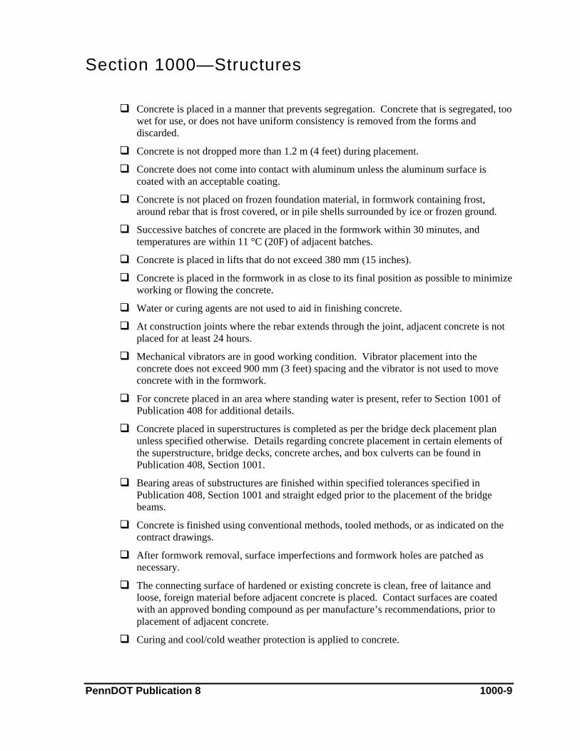
Section 1000—Structures
Concrete is placed in a manner that prevents segregation. Concrete that is segregated, too wet for use, or does not have uniform consistency is removed from the forms and discarded.
Concrete is not dropped more than 1.2 m (4 feet) during placement.
Concrete does not come into contact with aluminum unless the aluminum surface is coated with an acceptable coating.
Concrete is not placed on frozen foundation material, in formwork containing frost, around rebar that is frost covered, or in pile shells surrounded by ice or frozen ground.
Successive batches of concrete are placed in the formwork within 30 minutes, and temperatures are within 11 °C (20F) of adjacent batches.
Concrete is placed in lifts that do not exceed 380 mm (15 inches).
Concrete is placed in the formwork in as close to its final position as possible to minimize working or flowing the concrete.
Water or curing agents are not used to aid in finishing concrete.
At construction joints where the rebar extends through the joint, adjacent concrete is not placed for at least 24 hours.
Mechanical vibrators are in good working condition. Vibrator placement into the concrete does not exceed 900 mm (3 feet) spacing and the vibrator is not used to move concrete with in the formwork.
For concrete placed in an area where standing water is present, refer to Section 1001 of Publication 408 for additional details.
Concrete placed in superstructures is completed as per the bridge deck placement plan unless specified otherwise. Details regarding concrete placement in certain elements of the superstructure, bridge decks, concrete arches, and box culverts can be found in Publication 408, Section 1001.
Bearing areas of substructures are finished within specified tolerances specified in Publication 408, Section 1001 and straight edged prior to the placement of the bridge beams.
Concrete is finished using conventional methods, tooled methods, or as indicated on the contract drawings.
After formwork removal, surface imperfections and formwork holes are patched as necessary.
The connecting surface of hardened or existing concrete is clean, free of laitance and loose, foreign material before adjacent concrete is placed. Contact surfaces are coated with an approved bonding compound as per manufacture’s recommendations, prior to placement of adjacent concrete.
Curing and cool/cold weather protection is applied to concrete.
PennDOT Publication 8 1000-9

Section 1000—Structures D. Concrete Curing
This subchapter addresses methods of curing concrete. Curing is one of the key elements in quality concrete construction, as it directly affects concrete strength, appearance, and durability. Curing is best accomplished by maintaining a stable environment, in terms of temperature and moisture, for a required period of time after the concrete is placed.
References Publication 408, Section 704 (Cement Concrete)
Publication 408, Section 711 (Concrete Curing Materials and Admixtures)
Publication 408, Section 1001 (Cement Concrete Structures)
PTM 611
Approved Shop Drawings
Contract Special Provisions
Approved Concrete Quality Control Plan
Approved Concrete Mix Design
Material & Equipment Materials for the work include those to maintain moisture, such water, membrane spray cure, burlap, polyurethane, and weeper hoses. Blankets, straw, foam insulation, heaters, plastic, and radiant heat may be used for maintaining temperatures during cool and cold weather curing. Curing boxes, lime baths, and storage areas are required for the protection and curing of concrete cylinders, and high/low thermometers are required to accurately maintain proper curing temperatures for cylinders and placed concrete.
Construction Methods Prior to construction, the contractor submits a concrete quality control plan for approval. The plan must include targeted curing temperature requirements for placed concrete.
When concrete arrives on the project, the contractor is required to make compressive strength cylinders for both quality control and acceptance, which are then placed in a curing box for the first 24 hours after they are molded. After 24 hours, the quality control cylinders are cured in the same manner as the placed concrete; the acceptance are taken to a lime bath.
After concrete is placed for a particular element and all finish work is complete, curing is placed and maintained as required. The contractor may flood cure, place wet burlap and polyurethane, apply membrane spray cure, cover with insulation, or apply heating as required by the weather conditions for that particular concrete placement.
Measuring & Payment Methods Payment for curing is incidental to the placed concrete.
PennDOT Publication 8 1000-10
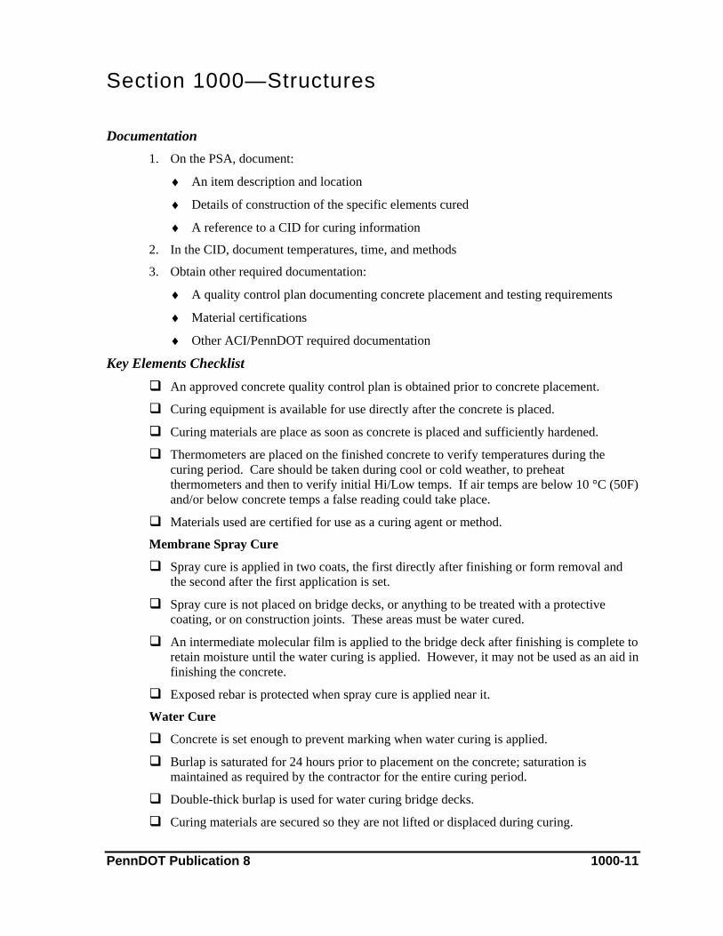
Section 1000—Structures Documentation
1. On the PSA, document:
♦ An item description and location
♦ Details of construction of the specific elements cured
♦ A reference to a CID for curing information
2. In the CID, document temperatures, time, and methods
3. Obtain other required documentation:
♦ A quality control plan documenting concrete placement and testing requirements
♦ Material certifications
♦ Other ACI/PennDOT required documentation
Key Elements Checklist An approved concrete quality control plan is obtained prior to concrete placement.
Curing equipment is available for use directly after the concrete is placed.
Curing materials are place as soon as concrete is placed and sufficiently hardened.
Thermometers are placed on the finished concrete to verify temperatures during the curing period. Care should be taken during cool or cold weather, to preheat thermometers and then to verify initial Hi/Low temps. If air temps are below 10 °C (50F) and/or below concrete temps a false reading could take place.
Materials used are certified for use as a curing agent or method.
Membrane Spray Cure
Spray cure is applied in two coats, the first directly after finishing or form removal and the second after the first application is set.
Spray cure is not placed on bridge decks, or anything to be treated with a protective coating, or on construction joints. These areas must be water cured.
An intermediate molecular film is applied to the bridge deck after finishing is complete to retain moisture until the water curing is applied. However, it may not be used as an aid in finishing the concrete.
Exposed rebar is protected when spray cure is applied near it.
Water Cure
Concrete is set enough to prevent marking when water curing is applied.
Burlap is saturated for 24 hours prior to placement on the concrete; saturation is maintained as required by the contractor for the entire curing period.
Double-thick burlap is used for water curing bridge decks.
Curing materials are secured so they are not lifted or displaced during curing. PennDOT Publication 8 1000-11
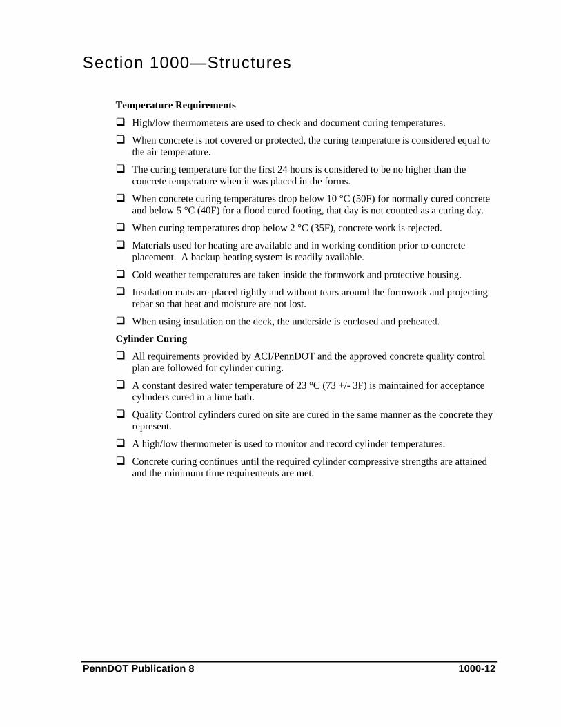
Section 1000—Structures
Temperature Requirements
High/low thermometers are used to check and document curing temperatures.
When concrete is not covered or protected, the curing temperature is considered equal to the air temperature.
The curing temperature for the first 24 hours is considered to be no higher than the concrete temperature when it was placed in the forms.
When concrete curing temperatures drop below 10 °C (50F) for normally cured concrete and below 5 °C (40F) for a flood cured footing, that day is not counted as a curing day.
When curing temperatures drop below 2 °C (35F), concrete work is rejected.
Materials used for heating are available and in working condition prior to concrete placement. A backup heating system is readily available.
Cold weather temperatures are taken inside the formwork and protective housing.
Insulation mats are placed tightly and without tears around the formwork and projecting rebar so that heat and moisture are not lost.
When using insulation on the deck, the underside is enclosed and preheated.
Cylinder Curing
All requirements provided by ACI/PennDOT and the approved concrete quality control plan are followed for cylinder curing.
A constant desired water temperature of 23 °C (73 +/- 3F) is maintained for acceptance cylinders cured in a lime bath.
Quality Control cylinders cured on site are cured in the same manner as the concrete they represent.
A high/low thermometer is used to monitor and record cylinder temperatures.
Concrete curing continues until the required cylinder compressive strengths are attained and the minimum time requirements are met.
PennDOT Publication 8 1000-12

Section 1000—Structures E. Protective Coating of Reinforced Concrete Surfaces
This subchapter covers the application of protective coatings (sealers) for reinforced concrete surfaces.
References Publication 408, Section 503 (Protective Coating for Cement Concrete)
Publication 408, Section 1019 (Protective Coating for Reinforced Concrete Structures)
Bulletin 15, Approved Construction Materials
Approved Contract Drawings
Contract Special Provisions
Material & Equipment Materials for this process include boiled linseed oil, epoxy resin, and penetrating sealer. To ensure that the material is free of defects, it must be stored in properly sealed containers, is not frozen, and each part of a two-component systems (those which require mixing) is fully packaged.
These sealers can be applied using hand or power sprayers, brushes, rollers, brooms, or other devices that ensure proper application.
Construction Methods The area to be sealed must be clean and free of all foreign debris. When using epoxy resin, the surface must be cleaned with a muriatic acid solution, sandblasting, or other approved method.
The process may require one or two coats of sealant, depending on the material used. Typically, the sealer is sprayed on. Boiled linseed oil and epoxy resin should be applied in two coats, with a drying period of 24 hours between coats. When penetrating sealer is used, only one coat may be required; however, follow the manufacturer’s instructions for precise application.
Measuring & Payment Methods Protective coatings are paid as part of the structure lump sum or by the square meter (square yard). This measurement can be used to determine the amount of sealant required, based on its application rate per square meter (square yard).
The Department will pay for additional maintenance and protection of traffic, if necessary for the application of additional protective coating to bridge decks experiencing excessive cracking, as specified in Section 110.03(d). Payment can be made daily or at the completion of this activity. If applicable, partial payment can be made as agreed to by the contractor and inspection staff. Typically, these materials are not paid as stored materials.
PennDOT Publication 8 1000-13

Section 1000—Structures Documentation
1. On the PSA, document:
♦ An item description and location
♦ Structural element sealed
♦ Calculation of the m2 (square yard) for payment
♦ Calculation of the application rate
♦ Payment record
♦ Any other documentation to detail the day’s activities
2. Obtain other required documentation:
♦ Material certifications
♦ Other ACI/PennDOT required documentation
Key Elements Checklist Area to be sealed is measured and the amount of material required is calculated.
The surface is thoroughly clean and dry.
The sealant used is certified and correct.
Boiled Linseed Oil
Membrane-forming curing compound is not applied to the area where boiled linseed oil is to be applied.
Linseed oil is applied to a dry surface as soon as possible after completion of construction, except for bridge decks (for which there is a waiting period of 14 days).
Linseed oil is applied only when the temperature is between 2 °C (35F) and 40 °C (100F).
The initial coat is checked for total and uniform coverage, assuring that the minimum coverage rate of 1L/11 m2 (0.02 gal/square yard) is met. Four hours elapses before traffic is permitted.
The second coat is applied 24 hours after the application of the first coat. Inspection verifies that total and uniform coverage has been achieved. Traffic is not permitted within six hours of application of the second coat.
Epoxy Resin
Membrane-forming curing compound is not applied to areas where resin is to be applied.
Epoxy resin is applied 28 days after the concrete is placed, unless otherwise permitted.
All surfaces to be sealed are cleaned with a muriatic acid solution, sandblasting, or other acceptable method.
PennDOT Publication 8 1000-14

Section 1000—Structures
Resin is applied only when the temperature is between 16 °C (60F) and 32 °C (90F).
The initial coat is checked for total and uniform coverage, ensuring that the specified rate of application is met.
Twenty-four hours elapses between the first and second coats, and total and uniform coverage has been achieved.
A representative sample of each component will be taken for the required tests.
Penetrating Sealer
The sealer has been applied according to the manufacturer’s instructions.
PennDOT Publication 8 1000-15
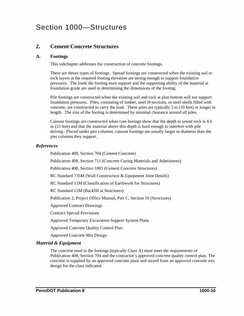
Section 1000—Structures 2. Cement Concrete Structures
A. Footings This subchapter addresses the construction of concrete footings.
There are threes types of footings. Spread footings are constructed when the existing soil or rock layers at the required footing elevation are strong enough to support foundation pressures. The loads the footing must support and the supporting ability of the material at foundation grade are used in determining the dimensions of the footing.
Pile footings are constructed when the existing soil and rock at plan bottom will not support foundation pressures. Piles, consisting of timber, steel H-sections, or steel shells filled with concrete, are constructed to carry the load. These piles are typically 3 m (10 feet) or longer in length. The size of the footing is determined by minimal clearance around all piles.
Caisson footings are constructed when core borings show that the depth to sound rock is 4.6 m (15 feet) and that the material above this depth is hard enough to interfere with pile driving. Placed under pier columns, caisson footings are usually larger in diameter than the pier columns they support.
References Publication 408, Section 704 (Cement Concrete)
Publication 408, Section 711 (Concrete Curing Materials and Admixtures)
Publication 408, Section 1001 (Cement Concrete Structures)
BC Standard 735M (Wall Construction & Equipment Joint Details)
RC Standard 11M (Classification of Earthwork for Structures)
RC Standard 12M (Backfill at Structures)
Publication 2, Project Office Manual, Part C, Section 10 (Structures)
Approved Contract Drawings
Contract Special Provisions
Approved Temporary Excavation Support System Plans
Approved Concrete Quality Control Plan
Approved Concrete Mix Design
Material & Equipment The concrete used in the footings (typically Class A) must meet the requirements of Publication 408, Section 704 and the contractor’s approved concrete quality control plan. The concrete is supplied by an approved concrete plant and mixed from an approved concrete mix design for the class indicated.
PennDOT Publication 8 1000-16
Section 1000—Structures
In addition to concrete, the contractor’s materials include steel or wood formwork, rebar, and rebar support systems (e.g., mortar blocks, wire chairs, and plastic chairs).
The contractor uses various equipment and materials for excavation, lifting, and concrete finishing. Excavation activities incorporate track hoes, dump trucks, and hydraulic hammers. Cranes, man lifts, track hoes, and other acceptable equipment are used for lifting. Concrete buckets, vibrators, finishing tools, and concrete testing equipment are used in conjunction with concrete placement.
Construction Methods Prior to construction, the contractor’s engineer provides the footing layout, using grade stakes showing the depth of cuts and work points. The contractor then excavates to the required elevation, and, if necessary, constructs a temporary excavation support system approved by the structure control engineer as the excavation progresses. This system may be necessary if one or more of the following conditions exists during excavation: the depth of the excavation exceeds 1.2 m (4 feet), the extracted material is very unstable, or the required slope lay back cannot be achieved. Refer to Chapter 8 for information on temporary excavation support systems.
The contractor constructs the required footings, and if appropriate, installs piling. (Reference Chapters 3, 4, and 6 for details on piles, caissons, and soldier pile walls.) If spread footings are required, the district structure control engineer reviews and approves the bottom of footing elevation after excavation. If the bottom of footing elevation is found to be of unstable material the area is under cut as directed by the structure control engineer. The under cut is then back filled with acceptable material to the bottom of footer elevation. The contractor’s engineer then lays out the footings with necessary work points and the contractor sets the formwork using alignment, grade, and other required dimensions set by the contractor’s surveyor and the contract drawings. All materials to be embedded in the concrete, including rebar, are secured to the formwork as required.
The contractor’s PennDOT certified concrete technician tests the concrete in accordance with the specifications and the approved concrete quality control plan. The contractor then places the concrete and compressive strength cylinders are molded as specified in Publication 408, Section 704. The lifts used to place the concrete cannot exceed 380 mm (15 inches) and the concrete must be vibrated as required.
Once the concrete is finished, appropriate curing is placed. (Refer to Chapter 1.D. regarding curing.) Formwork is removed after a specified period, and if needed, additional curing is completed after the formwork is removed. After specified strengths in the concrete cylinder breaks are achieved, all curing is removed.
Measuring & Payment Methods Excavation is paid as part of the Class 3 excavation line item under the structure lump sum or in cubic meter (cubic yard). Under cut areas will be paid by additional Class 1 excavation in cubic meter (cubic yard). Rebar is paid in kilogram (pound) under a separate line item number. Concrete is paid as part of the concrete line item under the structure lump sum or in cubic meter (cubic yard). Formwork and curing is incidental to the concrete item number.
PennDOT Publication 8 1000-17
Section 1000—Structures
Measurements and payments for temporary excavation support, piles, and drilled caissons are made under an individual line item number.
Documentation 1. On the PSA, document:
♦ An item description and location
♦ Details of the day’s construction activities associated with the footings
♦ Reference to the Field Book and CID, if applicable
2. In the Field Book, document information regarding construction of the footings that is not included on the PSA, such as dimensions, volume calculations, and calculated pay quantities.
3. Ensure that concrete is properly documented:
♦ In the CID, document the required information for each load of concrete and the results of testing
♦ Obtain delivery tickets for each load of concrete as it arrives at the project
♦ Prior to concrete placement, obtain an approved concrete quality control plan and approved mix designs
♦ Obtain any other required PennDOT documents
Key Elements Checklist Excavation is completed to the bottom of the footing elevation. Contractor supplies
footing grade elevation shots.
The district structure control engineer has inspected and approved the bottom of spread footings elevation prior to concrete placement, if applicable.
The contractor has removed water from the excavation and has measures in place to prevent water from entering the excavation.
If the footing has been placed within a waterway, a cofferdam has been placed (if required).
Where the material at the bottom of the footing is different than expected, the structure control engineer has requested that additional samples be taken at various depths to determine what action may be required.
If additional excavation is necessary to achieve suitable material, the contractor has been informed by PennDOT to perform the excavation and to be compensated for the work.
Accurate measurements of the length, width, and depth of the excavation are kept.
Formwork is constructed to match the contract drawings.
Formwork is properly aligned, plumb, and adequately braced.
PennDOT Publication 8 1000-18

Section 1000—Structures
Formwork is clean and oiled as specified to ensure its removal does not damage the new concrete. Formwork that is reused has no obvious defects.
Embedded elements are secured to formwork prior to concrete placement.
When wooden spreaders are removed, steel spacers are embedded in the concrete as required.
Formwork is removed after a specified period of time and/or cylinder breaks are sufficient.
Rebar mark, size, type, quality, length, and bending configuration are verified.
Bar spacing and clearances are checked relative to the plans.
On epoxy-coated rebar, all areas of damage have been touched-up with approved epoxy paint.
Splice and embedment lengths are as shown on the contract drawings.
Mechanical splices are tested prior to placing concrete
All rebar is certified and certification paperwork is on file at the job office.
A copy of the approved concrete quality control plan is on site and in the inspector’s possession.
Forms and rebar are accepted by inspection.
The concrete air meters are calibrated.
The concrete plant has a release for concrete delivery.
The contractor’s certified concrete technician has tested the concrete in accordance to the specifications and the concrete quality control plan. Test results are within specified limits.
A sufficient number of testing cylinders has been molded for the required compressive strength testing.
Concrete is placed in lifts not exceeding 380 mm (15 inches) and is properly vibrated.
During placement, concrete does not drop more than 1.2 m (4 feet).
The weather conditions conform to specifications.
Concrete is finished as required.
Curing is placed. Water curing, spray curing, or a combination of both may be used.
Temperatures are verified during the curing period.
If insulating blankets are used, they are properly secured.
PennDOT Publication 8 1000-19
Section 1000—Structures B. Abutments
This subchapter addresses the construction of concrete abutment walls.
References Publication 408, Section 704 (Cement Concrete)
Publication 408, Section 711 (Concrete Curing Materials and Admixtures)
Publication 408, Section 1001 (Cement Concrete Structures)
BC Standard 735M (Wall Construction & Expansion Joint Detail)
RC Standard 11M (Classification of Earthwork for Structures)
RC Standard 12M (Backfill at Structures)
Publication 2, Project Office Manual, Part C, Section 10 (Structures)
Approved Contract Drawings
Contract Special Provisions
Approved Concrete Quality Control Plan
Approved Concrete Mix Design
Material & Equipment Materials used for abutments includes steel or wood formwork, rebar, and concrete (typically Class A), as well as rebar support systems which incorporate items such as wire or plastic chairs. The concrete must be supplied by an approved concrete plant and mixed using an approved mix design for the class indicated.
The contractor uses a variety of lifting equipment, including cranes, man-lifts, and track hoes. Concrete buckets, vibrators, finishing tools, and concrete testing equipment are used in conjunction with concrete placement. Often, drawings require that abutments incorporate architectural treatment.
Construction Methods The contractor’s engineer provides the layout of the abutment wall, with necessary work points, on top of the footing and the formwork is set to the work points according to the contract drawings. Rebar is then placed and secured.
The contractor’s PennDOT certified concrete technician tests the concrete in accordance with the specifications and the approved concrete quality control plan.
The contractor places hoppers and tremie tubes or other acceptable devices within the formwork to prevent concrete from free falling more than 1.2 m (4 feet). Concrete is tested in accordance to the approved quality control plan and compressive strength cylinders are molded. The concrete is placed in lifts not to exceed 380 mm (15 inches) and is vibrated as required. The concrete is finished on top of the abutment as shown on the approved contract drawings. Bearing areas of substructures are finished as required by specifications.
PennDOT Publication 8 1000-20
Section 1000—Structures
After concrete placement, curing is placed. More than one type of curing can be used, depending on the part of the abutment being cured. (Refer to Chapter 1.D. regarding curing.) Formwork is removed after the specified time; if needed, additional curing is placed after formwork removal.
After specified concrete strengths are achieved, all curing is removed.
Measuring & Payment Methods Concrete is paid as part of the concrete line item under the structure lump sum or by the cubic meter (cubic yard). Rebar may be measured and paid per kilogram (pound) or as part of a lump sum. Protective coatings for concrete surfaces may be paid in square meter (square yard) or as part of the lump sum.
Formwork and curing are incidental to the concrete item number.
Documentation 1. On the PSA, document:
♦ An item description and location
♦ Details of the construction activities for the abutment wall occurring that day
♦ Reference to the Field Book and CID, if applicable
2. In the Field Book, document the required information regarding the construction of the abutment wall that is not in the PSA, such as dimensions, volume calculations, and calculated pay quantities.
3. Ensure that concrete is properly documented:
♦ In the CID, document the required information for each load of concrete and the results of testing
♦ Obtain delivery tickets for each load of concrete as it arrives at the project
♦ Prior to concrete placement, obtain an approved concrete quality control plan and approved mix designs
♦ Obtain any other required ACI/PennDOT documents
Key Elements Checklist A minimum of 12 hours elapses between footing placement and abutment wall
construction. If the footings are on piles, construction cannot begin until 48 hours have elapsed.
If required, PennDOT approved shop/working drawings for formwork are obtained prior to commencing construction. Written acceptance is obtained from the contractor’s engineer upon completion of the formwork. A copy of the written acceptance from the contractor’s engineer is placed in the job files prior to the concrete placement.
Formwork is built to match the contract drawings.
PennDOT Publication 8 1000-21
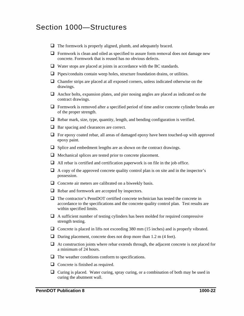
Section 1000—Structures
The formwork is properly aligned, plumb, and adequately braced.
Formwork is clean and oiled as specified to assure form removal does not damage new concrete. Formwork that is reused has no obvious defects.
Water stops are placed at joints in accordance with the BC standards.
Pipes/conduits contain weep holes, structure foundation drains, or utilities.
Chamfer strips are placed at all exposed corners, unless indicated otherwise on the drawings.
Anchor bolts, expansion plates, and pier nosing angles are placed as indicated on the contract drawings.
Formwork is removed after a specified period of time and/or concrete cylinder breaks are of the proper strength.
Rebar mark, size, type, quantity, length, and bending configuration is verified.
Bar spacing and clearances are correct.
For epoxy coated rebar, all areas of damaged epoxy have been touched-up with approved epoxy paint.
Splice and embedment lengths are as shown on the contract drawings.
Mechanical splices are tested prior to concrete placement.
All rebar is certified and certification paperwork is on file in the job office.
A copy of the approved concrete quality control plan is on site and in the inspector’s possession.
Concrete air meters are calibrated on a biweekly basis.
Rebar and formwork are accepted by inspectors.
The contractor’s PennDOT certified concrete technician has tested the concrete in accordance to the specifications and the concrete quality control plan. Test results are within specified limits.
A sufficient number of testing cylinders has been molded for required compressive strength testing.
Concrete is placed in lifts not exceeding 380 mm (15 inches) and is properly vibrated.
During placement, concrete does not drop more than 1.2 m (4 feet).
At construction joints where rebar extends through, the adjacent concrete is not placed for a minimum of 24 hours.
The weather conditions conform to specifications.
Concrete is finished as required.
Curing is placed. Water curing, spray curing, or a combination of both may be used in curing the abutment wall.
PennDOT Publication 8 1000-22

Section 1000—Structures
Thermometers are placed on the finished concrete to verify temperatures during the curing period. Care should be taken during cool or cold weather, to preheat thermometers and then to verify initial Hi/Low temps. If air temps are below 10 °C (50F) and/or below concrete temps a false reading could take place.
If insulating blankets are needed, they are properly secured during windy weather.
Bearing areas of substructures are finished as required.
After the abutment wall concrete is placed, superstructure beams cannot be erected on top of the abutment wall for a minimum of three days beyond placement and then only if the concrete has obtained the required minimum strength as specified in Publication 408, Section 1001.
Backfill operations behind the abutment wall may not begin until seven days after placing the last concrete and then only if the concrete has achieved the seven-day minimum mix design compressive strength as specified in Publication 408.
PennDOT Publication 8 1000-23

Section 1000—Structures C. Integral Abutments
This chapter covers the construction procedures for constructing an integral abutment structure. An integral abutment consists of the piles, pile cap, girders, (steel or concrete) end diaphragms, deck and approach slabs all being cast monolithically by reinforcement steel and concrete.
References Publication 408, Section 704 (Cement Concrete)
Publication 408, Section 1001 (Cement Concrete Structures)
Publication 408, Section 1002 (Reinforcement)
Publication 408, Section 1005 (Piles)
BC standard 788M (Neoprene Pads under Girders)
RC Standard 12M (Structure Backfill)
Approved Structure Plans
Contract Special Provisions
Material & Equipment The material required to construct the integral abutment structure would be specified in the project documents such as the plan drawings and contract special provisions. The piles used in the abutment would meet the requirements of the structure plans and Publication 408 specifications. The class of concrete required would be supplied by an approved concrete plant and would be tested by the contractor’s technician before placement to insure it meets the requirements of Publication 408.
The contractor would place reinforcement as shown on the plan drawings, which would be checked by the inspector to insure that the reinforcement has the required size and spacing. All material would be certified by the contractor on Form CS-4171 that it meets the requirements of the applicable Publication 408 section.
The contractor may need excavating equipment such as a track excavator, backhoe, or a front end loader capable of excavating the abutment foundation to the required dimensions and elevations. A drill capable of pre-drilling holes to the size and depth required for the pile installation would be needed. The contractor would need a pile hammer capable of driving piles to the required depth. The pile hammer data would be submitted by the contractor to the department for approval before driving any piles. The contractor would need a crane of adequate size to set the required girders. The crane also might be used to place concrete with a concrete bucket. The contractor would need a deck finishing machine capable of finishing the deck concrete to the required elevation, cross slope, and texture.
The contractor and the inspection staff would need concrete testing equipment used to test the concrete that is to be placed to insure it meets the requirements of Publication 408 specifications.
PennDOT Publication 8 1000-24

Section 1000—Structures Construction Methods
The contractor’s engineer lays out the locations for the abutments and the abutment foundations are excavated as per plan. Pile locations are laid out in the abutments and these locations are predrilled to the required diameter and depth. The piles are set in the predrilled holes and the space around the pile is filled with sand or pea gravel. The piles are then driven to the plan required refusal. The contractor constructs forms to the plan dimensions for the pile cap. After the forms are constructed, reinforcement as shown on the plan drawings is placed. The contractor then places the required class of concrete in the pile cap forms to the bottom of girder elevation. After the concrete is cured and meets the required strength, the type of girders indicated on the plan are set in place. The contractor then sets forms and places reinforcement on the deck and end diaphragms as shown on the structure plan. The contractor sets up a concrete deck finishing machine and a dry run is performed to insure the deck is the plan depth, the reinforcement has the required clearance, and the deck has the required cross slope. After the dry run has been performed and approved by the inspector, the contractor places, finishes and cures the required class of concrete to within 1.2 m (4 feet) of the front faces of the abutments. Concrete is then placed in the end diaphragms and after a 2 hour time elapse the concrete in the 1.2 m (4 feet) blockout in the deck at the front face of the abutment is placed. The wing walls are then constructed as shown on plan and after the deck concrete has cured and meets the required strength, the parapets are constructed as indicated on the structure plan.
Measuring & Payment Methods The structure is paid as a lump sum. Percentages of the lump sum would be paid on a PSA as the structure work is completed.
Documentation 1. On the PSA, document:
♦ An item description and location
♦ Details of the construction activities for the abutment wall occurring that day
♦ Reference to the Field Book and CID, if applicable
2. In the Field Book, document the required information regarding the construction of the abutment wall that is not in the PSA, such as dimensions, volume calculations, and calculated pay quantities.
3. Ensure that concrete is properly documented:
♦ In the CID, document the required information for each load of concrete and the results of testing
♦ Obtain delivery tickets for each load of concrete as it arrives at the project
♦ Prior to concrete placement, obtain an approved concrete quality control plan and approved mix designs
♦ Obtain any other required ACI/PennDOT documents
PennDOT Publication 8 1000-25

Section 1000—Structures
4. In a Pile Log, document all of the necessary information (e.g., pile length and size, splice length, depth of penetration, blow counts) about the pile prior, during, and after driving
Key Elements Checklist Verify that the abutment foundations are excavated to plan dimensions and elevations.
Verify that the pile locations are laid out as per plan.
Verify the pile pre-drilling to insure holes are drilled to required diameter and depth.
Verify that the piles are set in pre-drilled holes and the void around the piles filled with sand or pea gravel before driving the piles.
Verify that the deck concrete is placed before the concrete is placed in the end diaphragms except the 1.2 m (4 feet) portion of the deck from the front face of the abutment, which will be placed two hours after placing the concrete in the end diaphragms
Verify that all work is performed as per plan and specifications.
PennDOT Publication 8 1000-26

Section 1000—Structures D. Piers
This subchapter addresses the construction concrete pier sections above the footings.
There are a variety of pier types, as well as methods to construct them. This subchapter specifically discusses hammerhead piers, multi-column bent piers, and solid shaft wall type piers.
References Publication 408, Section 704 (Cement Concrete)
Publication 408, Section 711 (Concrete Curing Materials and Admixtures)
Publication 408, Section 1001 (Cement Concrete Structures)
Publication 408, Section 1019 (Protective Coating for Reinforced Concrete Structures)
BC Standard 735M (Wall Construction & Expansion Joint Details)
RC Standard 11M (Classification of Earthwork for Structures)
RC Standard 12M (Backfill at Structures)
Publication 2, Project Office Manual, Part C, Section 10 (Structures)
Approved Structure Plans
Approved Shop Drawings
Contract Special Provisions
Approved Concrete Quality Control Plan
Approved Concrete Mix Design
Material & Equipment Class A concrete is usually used in the construction of piers. The concrete must be supplied from an approved concrete plant and mixed using an approved mix design for the class of concrete indicated. Large quantities of rebar and concrete, as well as membrane curing compounds and protective concrete coatings, are also used for pier construction.
Cranes, man-lifts, concrete pumps, track hoes, and other lifting equipment may be used to place formwork, rebar and concrete. Forms are usually made of steel or wood, and ties, spreaders, braces, bolts, chairs, and whalers may be required to hold pier formwork in place. Concrete buckets, vibrators, finishing tools, and concrete testing equipment are used in conjunction with concrete placement.
Due to the height of the work, additional safety equipment, including safety harnesses, lanyards, and rebar caps, is often required. Often, the drawings require that piers incorporate architectural treatment.
PennDOT Publication 8 1000-27

Section 1000—Structures Construction Methods
The contractor submits required shop drawings for approval prior to construction.
After the footing is constructed, the contractor ties additional rebar to the projected footing steel for the pier column/shaft sections. Formwork is then placed using alignment, grade, and other required dimensions from the structure plans set by the contractor’s surveyor.
For piers with caps, formwork (per approved shop drawings) and rebar are placed for the cap sections. Beam seats, dowels, bearings, and other embedded fixtures are accounted for in the forms prior to cap concrete placement. Due to the tight spacing of larger bars, some of the rebar in the top of the cap is left temporarily untied until the concrete reaches the rebar layer. This is done so that concrete can easily flow to the bottom of the cap with minimal segregation and free fall. Designers may incorporate a larger space in the cap rebar for this purpose.
The contractor’s PennDOT certified concrete technician tests the concrete in accordance with the specifications and approved concrete quality control plan. Concrete for the column/shaft sections placed and cured using approved methods.
Concrete is properly placed and cured in the cap sections. Once cured, a protective coating is applied to the concrete as required by the structure plans.
Measuring & Payment Methods Most of the pier construction is paid as part of the bridge lump sum.
Rebar may be measured and paid per kilogram (pound) or as part of a lump sum. Protective coatings for concrete surfaces may be paid in square meter (square yard) or as part of the lump sum. Formwork and curing are incidental to the concrete item number.
Documentation 1. On the PSA, document:
♦ An item description and location
♦ Details of construction of the specific methods and materials used for the particular pier construction
♦ A reference to the Field Book and CID, if applicable
2. In the Field Book, document:
♦ Dimensions of the area or element formed, for future dimension verification and concrete pay quantities
♦ An itemized list of the rebar placed including, the bar mark, size, number, length, weight, and any other important information
PennDOT Publication 8 1000-28

Section 1000—Structures
3. Ensure that concrete is properly documented:
♦ In the CID, document the required information for each load of concrete and the results of testing
♦ Obtain delivery tickets for each load of concrete as it arrives at the project
♦ Prior to concrete placement, obtain an approved concrete quality control plan and approved mix designs
♦ Obtain any other required ACI/PennDOT documents
4. Prior to placement, obtain shop drawings for cap formwork.
Key Elements Checklist Formwork is constructed to match the contract drawings.
Formwork is properly aligned, plumb, and adequately braced.
During footing construction, rebar projecting from the footing to the pier section is to the length specified in the bridge plans.
Work on pier stem sections does not proceed until footing concrete is in place for 48 hours for pile footings and 12 hours for other footings.
Rebar is tied in place or tied on the ground and placed using a crane or other lifting equipment.
Rebar in pier columns and caps is checked and its condition thoroughly documented.
Due to the visibility of piers, care is taken to provide quality formwork and good vibration techniques for concrete placement in all pier sections.
The contractor’s PennDOT certified concrete technician has tested the concrete in accordance to the specifications and the concrete quality control plan. Test results are within specified limits.
The weather conditions conform to specifications.
Concrete does not freefall more than 1.2 m (4 feet) and is placed in 380 mm (15 inches) maximum lifts. Elephant trunks, tremies, or concrete pumps may be used in this process.
Where formwork from previous concrete column lifts remains in place and is adequately braced, work may continue on upper sections of the column 24 hours after the concrete placement of the lower sections.
Where formwork from previous concrete column lifts does not remain in place or is supported by a previous lift, work may continue on upper sections five days after the concrete placement of the lower sections and only if the concrete attains the minimum compressive strength of the concrete.
Cap forms supported by pier columns are not placed until five days after the column concrete placement and then only if the required compressive strength of the column concrete is reached.
PennDOT Publication 8 1000-29
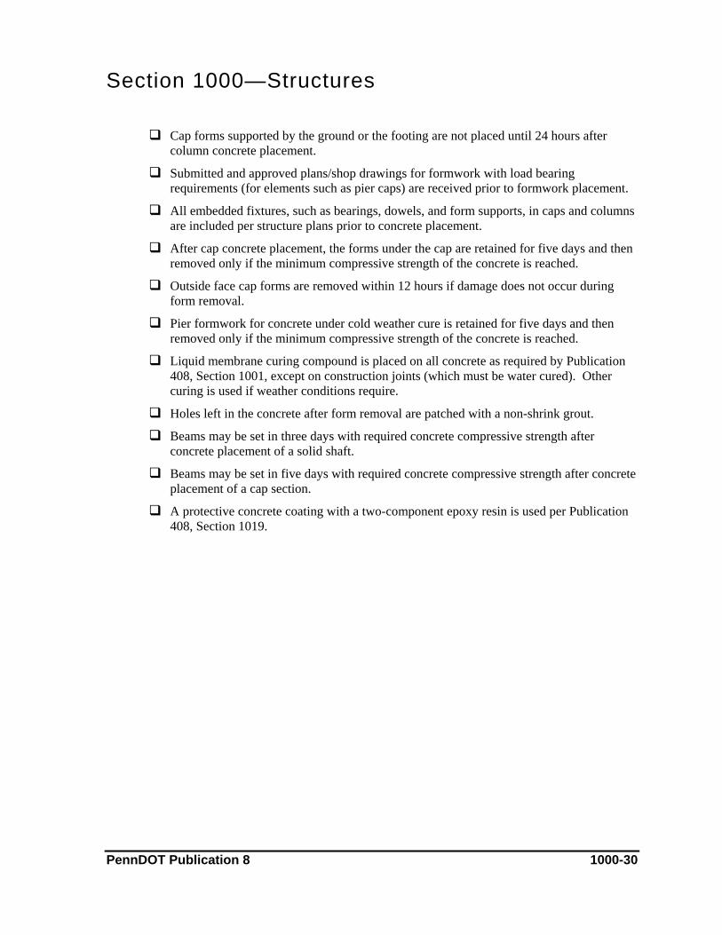
Section 1000—Structures
Cap forms supported by the ground or the footing are not placed until 24 hours after column concrete placement.
Submitted and approved plans/shop drawings for formwork with load bearing requirements (for elements such as pier caps) are received prior to formwork placement.
All embedded fixtures, such as bearings, dowels, and form supports, in caps and columns are included per structure plans prior to concrete placement.
After cap concrete placement, the forms under the cap are retained for five days and then removed only if the minimum compressive strength of the concrete is reached.
Outside face cap forms are removed within 12 hours if damage does not occur during form removal.
Pier formwork for concrete under cold weather cure is retained for five days and then removed only if the minimum compressive strength of the concrete is reached.
Liquid membrane curing compound is placed on all concrete as required by Publication 408, Section 1001, except on construction joints (which must be water cured). Other curing is used if weather conditions require.
Holes left in the concrete after form removal are patched with a non-shrink grout.
Beams may be set in three days with required concrete compressive strength after concrete placement of a solid shaft.
Beams may be set in five days with required concrete compressive strength after concrete placement of a cap section.
A protective concrete coating with a two-component epoxy resin is used per Publication 408, Section 1019.
PennDOT Publication 8 1000-30
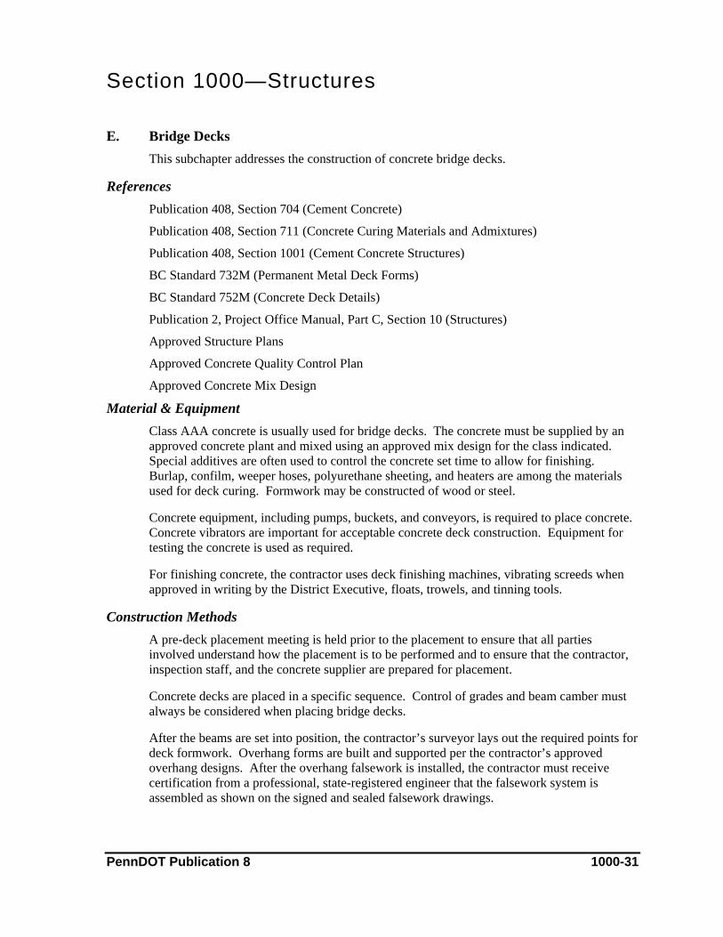
Section 1000—Structures E. Bridge Decks
This subchapter addresses the construction of concrete bridge decks.
References Publication 408, Section 704 (Cement Concrete)
Publication 408, Section 711 (Concrete Curing Materials and Admixtures)
Publication 408, Section 1001 (Cement Concrete Structures)
BC Standard 732M (Permanent Metal Deck Forms)
BC Standard 752M (Concrete Deck Details)
Publication 2, Project Office Manual, Part C, Section 10 (Structures)
Approved Structure Plans
Approved Concrete Quality Control Plan
Approved Concrete Mix Design
Material & Equipment Class AAA concrete is usually used for bridge decks. The concrete must be supplied by an approved concrete plant and mixed using an approved mix design for the class indicated. Special additives are often used to control the concrete set time to allow for finishing. Burlap, confilm, weeper hoses, polyurethane sheeting, and heaters are among the materials used for deck curing. Formwork may be constructed of wood or steel.
Concrete equipment, including pumps, buckets, and conveyors, is required to place concrete. Concrete vibrators are important for acceptable concrete deck construction. Equipment for testing the concrete is used as required.
For finishing concrete, the contractor uses deck finishing machines, vibrating screeds when approved in writing by the District Executive, floats, trowels, and tinning tools.
Construction Methods A pre-deck placement meeting is held prior to the placement to ensure that all parties involved understand how the placement is to be performed and to ensure that the contractor, inspection staff, and the concrete supplier are prepared for placement.
Concrete decks are placed in a specific sequence. Control of grades and beam camber must always be considered when placing bridge decks.
After the beams are set into position, the contractor’s surveyor lays out the required points for deck formwork. Overhang forms are built and supported per the contractor’s approved overhang designs. After the overhang falsework is installed, the contractor must receive certification from a professional, state-registered engineer that the falsework system is assembled as shown on the signed and sealed falsework drawings.
PennDOT Publication 8 1000-31

Section 1000—Structures
Deck pans (SIP forms) or removable wooden forms are placed between the beams per approved shop drawings (deck grade cuts and fills from contractor survey) and checked by a department representative. Deck rebar and other embedded fixtures in the deck are then placed per plans.
The deck finishing machine is placed on tracks usually attached to the overhang formwork. When using deck pans, the deck machine must run in the same direction as the laps of the deck pans. Deck machine tracks and cross slopes are adjusted as required to attain acceptable concrete finishing depths and verified with a dry run of the deck finishing machine over the entire deck as outlined in Publication 2, Project Office Manual, Part C, Section 10.
The contractor’s PennDOT certified technician tests the concrete in accordance with the specifications and the approved concrete quality control plan. The concrete is placed with a pump, bucket, conveyor, or other device and consolidated as required with concrete vibrator. A finish machine is used to finish the concrete to the correct depth and cross slope. Depths are checked periodically during placement as outlined in Publication 2, Project Office Manual, Part C, Section 10. Workers, using trowels, floats, and tinning rakes, will give the deck its final finish.
Materials such as burlap, heat, and weeper hoses, are placed for curing. After curing, a protective concrete coating (usually boiled linseed oil) is applied.
Measuring & Payment Methods Concrete for decks is paid as part of the lump sum bridge structure or by the cubic meter (cubic yard). Rebar is paid in kilogram (pound) or as part of the bridge lump sum.
Documentation 1. On the PSA, document:
♦ An item description and location
♦ Details of construction of the specific methods and materials used for deck construction
♦ Reference to the CID
♦ Reference to the Field Book or other documents containing the results of a dry run and an actual concrete depth check of the deck
♦ A payment calculation or reference to a pay calculation in the Field Book, if applicable
2. In the Field Book, document:
♦ Measurement and payment calculations
♦ The results of the deck finishing machine dry run and actual concrete placement depth check
♦ An itemized list of the rebar placed including, the bar mark, size, number, length, weight, and any other important information
PennDOT Publication 8 1000-32
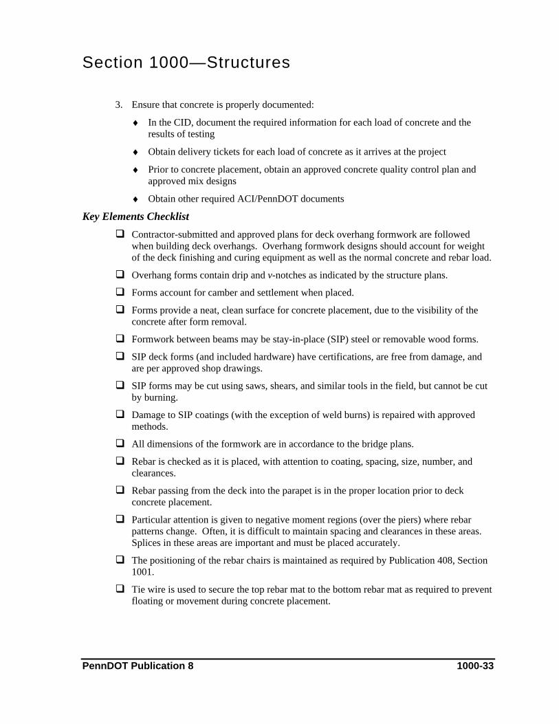
Section 1000—Structures
3. Ensure that concrete is properly documented:
♦ In the CID, document the required information for each load of concrete and the results of testing
♦ Obtain delivery tickets for each load of concrete as it arrives at the project
♦ Prior to concrete placement, obtain an approved concrete quality control plan and approved mix designs
♦ Obtain other required ACI/PennDOT documents
Key Elements Checklist Contractor-submitted and approved plans for deck overhang formwork are followed
when building deck overhangs. Overhang formwork designs should account for weight of the deck finishing and curing equipment as well as the normal concrete and rebar load.
Overhang forms contain drip and v-notches as indicated by the structure plans.
Forms account for camber and settlement when placed.
Forms provide a neat, clean surface for concrete placement, due to the visibility of the concrete after form removal.
Formwork between beams may be stay-in-place (SIP) steel or removable wood forms.
SIP deck forms (and included hardware) have certifications, are free from damage, and are per approved shop drawings.
SIP forms may be cut using saws, shears, and similar tools in the field, but cannot be cut by burning.
Damage to SIP coatings (with the exception of weld burns) is repaired with approved methods.
All dimensions of the formwork are in accordance to the bridge plans.
Rebar is checked as it is placed, with attention to coating, spacing, size, number, and clearances.
Rebar passing from the deck into the parapet is in the proper location prior to deck concrete placement.
Particular attention is given to negative moment regions (over the piers) where rebar patterns change. Often, it is difficult to maintain spacing and clearances in these areas. Splices in these areas are important and must be placed accurately.
The positioning of the rebar chairs is maintained as required by Publication 408, Section 1001.
Tie wire is used to secure the top rebar mat to the bottom rebar mat as required to prevent floating or movement during concrete placement.
PennDOT Publication 8 1000-33

Section 1000—Structures
Rebar is placed per plans, is free from damage, frost, dirt, and debris, and is tied 100% before concrete is ordered. Care is taken to prevent the operating deck finishing machine from damaging the rebar.
Rebar damaged during construction is repaired with an approved material or replaced.
Materials, such as beam stirrups, lifting eyes, diaphragm bars, and dowels, are coated.
All formwork and rebar is checked per structure plans.
Burlap is soaked in water tanks 24 hours in advance to insure moist condition.
An approved quality control and deck concrete placement plan is obtained. Planned procedures are per deck placement sequences as required by the structure plans.
The contractor’s PennDOT certified technician has tested the concrete in accordance to the specifications and the approved concrete quality control plan. Test results are within specified limits.
Weather conditions and forecasts are within the requirements of Publication 408, Sections 501 and 1001 to ensure that placement of concrete is feasible for that day.
A dry run of the finishing machine, including measuring and recording top rebar clearances, concrete depths, and out-to-out (deck width) measurements at the specified locations as required by Publication 2, Project Office Manual, Part C, Section 10, is performed and approved by the engineer. After the deck finishing machine is at the correct cross slope and a successful dry run has been completed, the deck machine and rails can no longer be adjusted without the consent of the engineer.
Expansion dam openings are set properly for current weather conditions.
Bulkhead material is ready in case operations are stopped unexpectedly for extended periods of time.
Scuppers are set and secured to the proper grade prior to deck concrete placement.
Concrete is placed in a continuous operation and in such a way that the finishing machine will not bulldoze the concrete.
The rate of concrete placement meets a minimum of 6 m (20 linear feet) per hour.
Concrete is discharged in a manner that prevents excessive loads on the formwork.
Concrete is carefully and properly vibrated before the finishing machine is run.
After concrete is vibrated, no walking or disturbing rebar extending into the parapet area is permitted.
Placed concrete is checked for depth and top mat rebar clearance per Publication 2, Project Office Manual, Part C, Section 10. Results are recorded and compared with the dry run depths.
After finishing, the concrete is checked with a 3 m (10 feet) straight edge for irregularities. High areas are cut and refinished, while low areas are filled, reconsolidated, and refinished.
PennDOT Publication 8 1000-34

Section 1000—Structures
Finished concrete is tinned using a tinning rake with tine spacing per Publication 408, Section 501.
Immediately after tinning, an intermediate monomolecular film (confilm) curing agent is applied. Additional coats are applied as needed to prevent the surface from drying before wet burlap is applied. The curing agent is not used to aid in the finishing of the concrete.
After intermediate curing is placed, the deck is water cured for seven days and as long as required to attain minimum compressive strengths (determined from concrete cylinder testing). Usually, two layers of wet burlap with weeper hoses are used in this process.
Curing temperatures of the deck are monitored closely and recorded in the CID for each day of the curing period.
Preparations (e.g., blankets, hay, heaters) for cool and cold weather curing are made. Low temperature readings, as indicated in Publication 408, Section 1001, may cause extended curing time. In severe cases, concrete may need to be removed.
Membrane curing is not permitted for bridge decks.
Formwork may be removed after the required time and the concrete strength requirements are met as indicated in Publication 408, Section 1001.
Parapets cannot be constructed until five days have elapsed since deck concrete placement and then only if concrete has reached the required strength.
Traffic is prohibited on the bridge until authorized and then only after 14 days and when minimum required compressive strength is reached.
A protective coating (usually boiled linseed oil) is applied after the 14-day waiting period or as required.
PennDOT Publication 8 1000-35

Section 1000—Structures F. Bridge Parapets
This subchapter addresses the construction of bridge parapets.
References Publication 408, Section 704 (Cement Concrete)
Publication 408, Section 711 (Concrete Curing Materials and Admixtures)
Publication 408, Section 1001 (Cement Concrete Structures)
BC Standard 752M (Concrete Deck Slab Details)
Approved Structure Plans
Approved Concrete Quality Control Plan
Approved Concrete Mix Design
Contract Special Provisions
Material & Equipment Class AA concrete is usually used for parapets. The concrete must meet the requirements of Publication 408, Section 704 and the approved concrete quality control plan. The concrete must be supplied by an approved concrete plant and mixed from an approved mix design for the class indicated. Formwork is composed of steel or wood.
Slip forming requires the use of a slip forming machine. Concrete vibrators contained in the slip form machine or in hand-held types and concrete testing equipment are important in acceptable parapet construction.
Construction Methods Fixed Form Parapets
Prior to formwork placement, rebar must be in place according to structure plans and specification requirement.
Formwork is placed using the alignment, grade, and other required dimensions set by the contractor’s surveyor from the structure plans. All materials to be embedded in the concrete, such as guide rail connections and noise wall attachments, are secured to the formwork as required.
The contractor’s PennDOT certified concrete technician tests the concrete in accordance with the specifications and the approved concrete quality control plan. Concrete is placed in lifts and consolidated with a concrete vibrator. After the concrete is placed, the formwork is removed according to the specifications. Lastly, the concrete is patched as required and proper curing performed.
PennDOT Publication 8 1000-36

Section 1000—Structures
Slip Form Parapets
Initially, a test section for the engineer’s approval is placed.
Prior to slip forming operations, rebar must be in place according to structure plans and specification requirement.
The contractor may place bulkheads in the parapet to create starting and ending points for the slip form concrete placement. The contractor then sets the alignment of the slip form machine and performs a dry run to check rebar clearances and proper parapet size, location, and other placement considerations.
The contractor’s PennDOT certified concrete technician tests the concrete in accordance with the specifications and approved concrete quality control plan. After an approved dry run, concrete supply trucks feed concrete to the slip form machine, which will place and consolidate the parapet concrete. After the concrete is extruded it is repaired as required by the engineer and finished with vertical brushing. Lastly, curing is performed as required.
Measuring & Payment Methods Concrete for parapets is paid as part of the lump sum bridge structure or as a cubic meter (cubic yard) item. Rebar is paid in kilogram (pound) or as part of the lump sum bridge item.
Documentation 1. On the PSA, document:
♦ An item description and location
♦ Details of construction of the specific methods and materials used for parapet construction
♦ Reference to the Field Book and CID
♦ A payment calculation or reference to a pay calculation in the Field Book, if applicable
2. In the Field Book, document:
♦ Measurement and payment calculations
♦ An itemized list of the rebar placed including, the bar mark, size, number, length, weight, and any other important information
3. Ensure that concrete is properly documented:
♦ In the CID, document the required information for each load of concrete and the results of testing
♦ Obtain delivery tickets for each load of concrete as it arrives at the project
♦ Prior to concrete placement, obtain an approved concrete quality control plan and approved mix designs
♦ Obtain any other required ACI/PennDOT documents
PennDOT Publication 8 1000-37
Section 1000—Structures Key Elements Checklist
An approved concrete bonding compound is used between new and existing concrete when specified.
The contractor’s PennDOT certified concrete technician has tested the concrete in accordance to the specifications and the approved concrete quality control plan. Test results are within specified limits.
The weather conditions conform to specifications.
All placement, consolidation, finishing, and curing equipment is ready for use prior to concrete delivery.
Vibrators, as specified in Publication 408, Section 1001, are used for concrete consolidation. Their use is especially important to the visual and structural results of concrete placement.
Concrete is properly cured as required, using membrane spray cure, wet burlap, heat, or other method as required by the specifications. Note: Membrane spray cure is not used if the concrete is treated with protective coatings, such as linseed oil or penetrating sealer.
Due to the small dimensions of a parapet, particular attention is given to maintaining proper curing temperatures.
Holes from formwork ties are patched with an approved non-shrink grout.
Deck concrete meets time and strength requirements, per Publication 408, Section 1001, before parapet concrete is placed.
Construction traffic and speed on the bridge after parapet concrete placement is regulated in accordance with Publication 408, Section 1001.
Parapets rejected due to defects are replaced at no additional cost to the Department.
Fixed Form Parapets
As parapets are visible to the public, parapet forms are clean, undamaged, in good condition, tight fitting, and oiled prior to concrete placement.
Chamfer strips, V notches, joints, rebar, and other embedded materials are in place and checked prior to concrete placement.
Concrete is placed in lifts as specified in Publication 408, Section 1001.
Forms are checked (with a straight edge) on the front, top, and rear for loss of dimension and shape before, during, and after concrete placement. Corrective action is taken as necessary.
Slip Form Parapets
Prior to placement, the contractor received approval for the concrete quality control plan.
For engineer approval, a 15 m (50 feet) slip form parapet test strip is constructed using the identical method used for the actual parapets. The test strip may be actual bridge parapet if the engineer approves. If the first test strip is not acceptable to the engineer,
PennDOT Publication 8 1000-38
Section 1000—Structures
modifications are made and a second test strip is made, as required. If the contractor or the engineer do not find the test strip results acceptable, fixed form parapets may need to be used.
Concrete cores are taken from the test section and sent to the Bureau of Construction and Materials.
Rebar clearance in the test section may be checked using a pachometer.
Concrete defects are repaired per the engineer’s approval. Defects, such as honeycombing, sags, and tears that cannot be fixed without water or extra concrete are rejected.
Prior to concrete placement, a dry run of the slip form machine is performed and documented to check the clearances of rebar and other fixtures in the parapet.
Rebar and bulkheads are braced, as required, to withstand the force of the slip form concrete placement.
Saw cut joints are marked prior to concrete placement so that the rebar is avoided when the saw cuts are made.
During slip forming, the only traffic allowed on the bridge is the slip form machine and the concrete delivery truck.
Slip form concrete is vertically brush finished.
Careful attention is given to freshly placed slip form concrete to ensure that there is no tearing, slumping, or loss of shape.
PennDOT Publication 8 1000-39

Section 1000—Structures G. Placement of Concrete Beams
This subchapter addresses the placement of concrete beams for bridge superstructures. In general, there are three types of concrete beams: I-beams, spread box beams, and adjacent box beams.
I-beams are I-shaped beams that are usually used for larger spans. Spread box beams are square or rectangular-shaped beams used for smaller spans. Adjacent box beams are similar to spread box beams except they are placed adjacent to one another and tend to be less deep than either I-beams or spread box beams. Adjacent box beams are used when the overall superstructure is required to be smaller due to vertical clearance restrictions.
References Publication 408, Section 1080 (Prestressed Concrete Bridge Superstructure)
BD Standard 620M (Lateral Bracing Criteria)
BD Standard 652M (Beam Size and Section Properties)
BD Standard 653M (Typical Framing Plans and Details)
BD Standard 655M (Typical Superstructure Sections)
BD Standard 656M (Typical Longitudinal Sections)
BD Standard 657M (I-Beam and Box Beam Bridges)
BC Standard 775M (Miscellaneous Prestress Details)
BC Standard 788M (Typical Waterproofing and Expansion Details)
Approved Structure Plans
Approved Shop Drawings
Contract Special Provisions
Material & Equipment Pre-stressed concrete beams should arrive on the project stamped by the plant inspector and constructed as per the approved shop drawings and stored in a manner similar to their final configuration on the bridge seats.
The contractor uses equipment such as cranes and skid beams to place the concrete beams. Cranes are used as required by the approved erection plans; skid beams are used for more difficult placements.
Non-shrink mortar should be used for filling bearing pad gaps and shear keys.
PennDOT Publication 8 1000-40

Section 1000—Structures Construction Methods
In General
Beams are placed on the beam seat bearing by crane. The contractor checks for gaps between the neoprene pad and the beam and, if necessary, lifts the beam, fills the gaps with non-shrink mortar (as specified in Publication 408, Section 1080), and resets the beam. An approved fall protection system is then placed on the beams
Adjacent Box Beams
Shear keys are cleaned prior to setting the beams. After the beams are set, longitudinal joints are filled with mortar and cured. Post tensioning strands are placed laterally through fabricated sleeves in the beams and post tensioned together as specified in BC Standard 775M. If a bituminous surface is to be used, a protective tar coating is then applied to the top of the beams.
Skid Beam
The contractor may use a skid beam for beam picks that are too far or too heavy for cranes to handle alone. A skid beam is a lighter beam that, unlike conventional concrete beams, can be picked at various locations on the beam to allow erection cranes to set the skid beam on near or far beam seats.
Once the skid beam is in place, the end of the beam that will actually sit on the far beam seat is removed from the rear carrier and placed on the skid beam; the other end of the beam remains on the carrier of the delivery truck. A near side crane—that which is on the same side as the delivery truck—guides the intended far side of the beam as the delivery truck backs toward the bridge, sliding the beam on the skid beam toward the far beam seat.
When the far end of the beam is guided near enough for safe picking on the far side, a second crane picks the far end of the beam. The near crane is then used to pick the near side of the beam from the delivery truck. At this point, the beam is then set using conventional methods.
Measuring & Payment Methods Concrete beams are paid as part of the lump sum bridge payment.
Documentation 1. On the PSA, document:
♦ An item description and location of the work
♦ Details of the construction, including specific methods and materials used for beam erection
♦ Payment calculation for the lump sum payment percentage
PennDOT Publication 8 1000-41

Section 1000—Structures
2. Obtain other required documentation:
♦ Approved shop drawings, showing beam detail and dimensions
♦ An approved erection plan detailing erection procedures as well as crane requirements
♦ A submitted and approved plan for a fall protection system
♦ Delivery tickets verifying that the beam delivered is the one that is required.
♦ Certification from the beam manufacturer.
Key Elements Checklist Approved beam shop drawings and erection plans are strictly followed.
Upon delivery, beams are checked for a plant inspector’s stamp. Items such as dimensions and camber are verified.
Beams are checked for damage, twisting, and cracking that may result from delivery and construction activities. Damaged beams may need to be replaced, as determined by the district structure control engineer.
Beams are stored in the upright position and are supported by skid plates in a manner similar to their final positioning on the bearing pads.
Beams are lifted using the manufacturer-provided lifting eyes located at the ends of the beams. A prestressed beam is never lifted at the middle section of the beam.
Crane location, size, picking, and setting procedures strictly adhere to the approved erection plans.
Skid beams (if applicable) are of the type and size required by the approved erection plans.
The location and concrete finish of the bearing/beam seat is checked prior to bearing and beam placement.
After the beam is set on the bearing, it is checked for proper overhang on the rear, left, and right side of the bearing.
When neoprene bearing pads are used, the bearing of the beam on the pad is checked for gaps and corrected per Publication 408, Section 1080.
Approved non-shrink mortar is used for gap repair.
Mortar is placed between the bearing seat and the bearing pad only after the initial beam set and no other corrective action can be used.
Beams are checked as they are placed for proper spacing.
Beams are supported after placement according to submitted and approved beam bracing plans and shop drawings. This is particularly important for large I-beams.
A submitted and approved fall protection system is placed on the beams before construction activity begins.
PennDOT Publication 8 1000-42
Section 1000—Structures
After beam placement is complete, waterproofing is applied as required by the structure plans.
Adjacent Box Beams
Shear key widths are checked prior to the placement of adjacent box beams.
Prior to beam setting, the shear keys are cleaned by sand blasting, water blasting, brushing, or other approved method.
Longitudinal joints are filled with non-shrink mortar and properly cured. After the mortar is placed, construction activity on the beams is halted for 24 hours.
Traffic is prohibited on the bridge for five days and then permitted only if the mortar has achieved the required compressive strength.
If a bituminous surface course is placed, a coal tar protective coating is applied to beams and shear keys, if required.
PennDOT Publication 8 1000-43
Section 1000—Structures H. Reinforced Concrete Retaining Walls
This subchapter addresses the construction of reinforced concrete retaining walls. These walls are similar to abutment walls, using mass and cantilevered forces to retain backfill material to varying heights for construction on or near the wall.
References Publication 408, Section 704 (Cement Concrete)
Publication 408, Section 711 (Concrete Curing Materials and Admixtures)
Publication 408, Section 1001 (Cement Concrete Structures)
Publication 408, Section 1019 (Protective Coating for Reinforced Concrete Structures)
Approved Shop Drawings
Contract Special Provisions
Approved Concrete Quality Control Plan
Approved Concrete Mix Design
Material & Equipment Material for the work includes steel or wood formwork, rebar and concrete (typically Class A). Ties, spreaders, braces, bolts, chairs, and whalers may be required to hold the formwork and rebar in place.
In constructing the retaining walls, the contractor uses lifting equipment, including cranes, man-lifts, track hoes, and other acceptable equipment. For placing concrete, concrete buckets, vibrators, concrete pumps, concrete testing equipment, and finishing tools are used. In addition, concrete curing and protective material is required. Often, drawings require that retaining walls incorporate architectural treatment.
Construction Methods After the footing is constructed, the contractor’s engineer provides layout of the wall on top of the footing with necessary work points. The contractor then sets the formwork to the work points per the contract drawings.
The contractor’s PennDOT certified concrete technician tests the concrete in accordance with the specifications and the approved concrete quality control plan. After the rebar is set and secured in the proper locations, the contractor places the concrete in the wall formwork in accordance with the approved quality control plan. Compressive strength cylinders are molded.
Following the concrete placement, the concrete is cured. More than one type of curing can be used, depending on the part of the wall cured. Formwork may be removed after a specified time. If needed, additional curing is placed after formwork removal. After achieving specified minimum strengths in the concrete cylinder breaks, all curing is removed.
PennDOT Publication 8 1000-44
Section 1000—Structures
Architectural treatment and protective coatings may be used as required by the plans or contract special provisions during wall construction.
Measuring & Payment Methods Rebar is paid in kilogram (pound) as a separate item number or as part of a lump sum. Concrete is paid by the cubic meter (cubic yard) or as a lump sum item. Formwork is incidental to the concrete placed in the forms. The Department will not make a deduction in measurement for anchor bolts, expansion plates, drainage openings, weep holes, pipes, or conduits if the volume displaced by an installation of opening does not exceed 0.4 cubic meter (1/2 cubic yard).
Protective coatings and architectural treatments may be paid by the square meter (square yards) or as part of the lump sum.
Documentation 1. On the PSA, document:
♦ An item description and location
♦ Details of the construction activities occurring that day
♦ A reference to the Field Book and CID, if applicable
2. In the Field Book, document:
♦ Information required to properly document the construction that is not on the PSA (e.g., dimensions, volume calculations, calculated pay quantities)
♦ An itemized list of the rebar placed, including the bar mark, size, number, length, weight, and any other important information
3. Ensure that concrete is properly documented:
♦ In the CID, document the required information for each load of concrete and the results of testing
♦ Obtain delivery tickets for each load of concrete as it arrives at the project
♦ Prior to concrete placement, obtain an approved concrete quality control plan and approved mix designs
♦ Obtain any other required ACI/PennDOT documents
Key Elements Checklist Construction of walls does not begin until 12 hours after footings are placed. If the
footing is on piles, 48 hours must elapse before construction begins.
If required, PennDOT approved shop/working drawings for form work are obtained prior to commencing construction. Upon completion of the formwork, written acceptance is obtained from the contractor’s engineer and a copy is placed in the job files.
The formwork is built to match the contract drawings.
PennDOT Publication 8 1000-45
Section 1000—Structures
The formwork is properly aligned, plumb, and adequately braced.
The formwork is clean and oiled, as specified, to ensure removal does not damage new concrete. Formwork that is reused has no obvious defects.
Due to the visibility of retaining wall faces, care is taken to provide quality formwork and good vibration techniques for concrete placement in all wall sections.
Water stops at joints are placed according to bridge construction standard drawings.
Pipes/conduits for weep holes, structure foundation drains, or utilities are accurately placed.
Chamfer strips are placed at all exposed corners, unless indicated otherwise on the drawings.
Anchor bolts and expansion plates are placed as indicated on the contract drawings.
Architectural treatment (if applicable) and any embedded elements are incorporated into the formwork as required.
Formwork is removed after a specified period of time and/or when cylinder breaks are sufficient.
Holes left in the concrete after form removal are patched with an approved non-shrink grout.
Rebar mark, size, type, quantity, length, and bending configuration is verified and documented as required.
Bar spacing and clearances are according to the plans.
For epoxy coated reinforcement bars, all areas of damaged epoxy have been touched-up with approved epoxy paint.
Splice and embedment lengths are as shown on the contract drawings.
Concrete air meters are calibrated biweekly and documented in the CID.
Release is provided to the concrete plant for the concrete delivery.
The contractor’s PennDOT certified concrete technician has tested the concrete in accordance to the specifications and the approved concrete quality control plan. Test results are within specified limits.
A sufficient number of testing cylinders are molded for required compressive strength testing.
Concrete does not free fall more than 1.2 m (4 feet).
Concrete is placed in lifts not exceeding 380 mm (15 inches).
Concrete is properly vibrated.
At construction joints where reinforcement bars extend through, the adjacent concrete is not placed for a minimum of 24 hours.
PennDOT Publication 8 1000-46

Section 1000—Structures
The weather conditions conform to specifications.
Concrete is finished as required.
All curing materials (e.g., wet burlap, blankets, heat) are ready prior to concrete placement.
Curing is placed immediately after the concrete is finished. Water curing, spray curing, or a combination of both may be utilized for curing the wall.
Thermometers are placed on the finished concrete to verify temperatures during the curing period.
Insulating blankets, if needed, are properly secured during windy weather.
Backfill operations behind retaining walls may not commence for seven days after the concrete is placed and then only if the concrete has achieved the seven-day minimum mix design compressive strength as specified in Publication 408.
Protective concrete coatings are placed as require by Publication 408, Section 1019 and the contract drawings.
PennDOT Publication 8 1000-47
Section 1000—Structures I. Reinforced Concrete Box Culverts
This subchapter addresses the placement of pre-cast and cast-in-place reinforced concrete box culverts.
References Publication 408, Section 704 (Cement Concrete)
Publication 408, Section 711 (Concrete Curing Materials and Admixtures)
Publication 408, Section 1001 (Cement Concrete Structures)
Publication 408, Section 1085 (Precast Reinforced Concrete Box Culvert)
BC Standard 775M (Miscellaneous Prestressed Details)
RC Standard 11M (Classification of Earthwork for Structures)
RC Standard 12M (Backfill at Structures)
Approved Structure Plans
Approved Shop Drawings
Contract Special Provisions
Approved Concrete Quality Control Plan
Approved Concrete Mix Design
Material & Equipment Material for the work may include pre-cast concrete box sections, which should arrive stamped with approved shop drawings. If cast-in-place box culverts are specified, the concrete used must be supplied from an approved concrete batch plant and mix using an approved mix design for the class indicated.
Post tensioning equipment and hardware may be required for pre-cast culverts, while concrete, rebar, formwork, and concrete testing equipment are necessary for cast-in-place culverts. Bracing, ties, and whalers are used to secure formwork for cast-in-place culverts.
Specified bedding and backfill material with requisite compaction equipment is required in placing both pre-cast and cast-in-place box culverts. In addition, the contractor must use lifting equipment capable of lifting culvert sections without causing damage to bedding material or box sections.
Construction Methods Pre-Cast Box Culverts
The contractor excavates the area to the required depth and removes unsuitable material or rock under the box sections. The approved bedding material is then placed and compacted, and end support blocks or other required elements under the culvert are seated. The contractor then places and post-tensions the pre-cast box sections according to the approved shop drawings.
PennDOT Publication 8 1000-48
Section 1000—Structures
Once the box sections are placed, the contractor places the wing walls, end walls, and associated structures. Voids, such as hand holes and lifting lugs, are grouted, and the sections are waterproofed. Lastly, structure backfill is placed and compacted.
Cast-in-Place Box Culverts
The excavation and bedding process is the same for cast-in-place box culverts as it is for pre-cast boxes. The contractor submits shop drawings and a concrete quality control plan for approval prior to the construction of formwork.
Once excavation and bedding is complete, the contractor places the formwork, rebar, and concrete for the base slab and short portions of each sidewall for the box culvert section as specified in Publication 408, Section 1001. Prior to concrete placement, the contractor’s PennDOT certified concrete technician tests the concrete in accordance with the specifications and the approved concrete quality control plan. Keyed construction joints are placed at the top of the short sidewalls to tie into the remaining upper sections of the sidewalls. The box sidewalls are then placed up to the top slab. After the sidewalls are allowed to settle, the top slab is placed.
After proper curing, forms are removed, voids are grouted, sections are waterproofed, and structure backfill is placed and compacted.
Measuring & Payment Methods Concrete box culverts are paid as a lump sum item. Formwork is incidental to the concrete placed in the forms.
Documentation 1. On the PSA, document:
♦ An item description and location
♦ Details of the day’s construction activities associated with the box culvert placement
♦ Reference to the Field Book and CID, if required
♦ Payment calculation for the lump sum payment percentage
2. In the Field Book, document information regarding rebar placement for cast-in-place box culverts.
3. Ensure that concrete is properly documented:
♦ In the CID, document the required information for each load of concrete and the results of testing
♦ Obtain delivery tickets for each load of concrete as it arrives at the project
♦ Prior to concrete placement, obtain an approved concrete quality control plan and approved mix designs
♦ Obtain any other required ACI/PennDOT documents
PennDOT Publication 8 1000-49
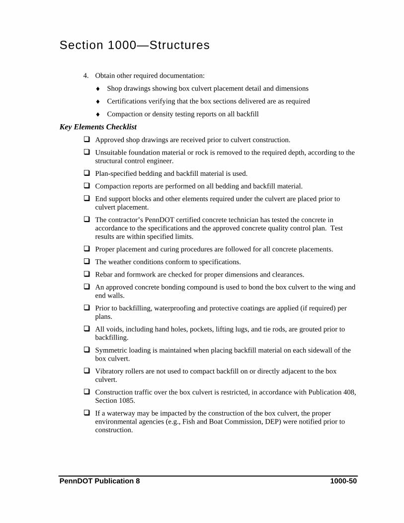
Section 1000—Structures
4. Obtain other required documentation:
♦ Shop drawings showing box culvert placement detail and dimensions
♦ Certifications verifying that the box sections delivered are as required
♦ Compaction or density testing reports on all backfill
Key Elements Checklist Approved shop drawings are received prior to culvert construction.
Unsuitable foundation material or rock is removed to the required depth, according to the structural control engineer.
Plan-specified bedding and backfill material is used.
Compaction reports are performed on all bedding and backfill material.
End support blocks and other elements required under the culvert are placed prior to culvert placement.
The contractor’s PennDOT certified concrete technician has tested the concrete in accordance to the specifications and the approved concrete quality control plan. Test results are within specified limits.
Proper placement and curing procedures are followed for all concrete placements.
The weather conditions conform to specifications.
Rebar and formwork are checked for proper dimensions and clearances.
An approved concrete bonding compound is used to bond the box culvert to the wing and end walls.
Prior to backfilling, waterproofing and protective coatings are applied (if required) per plans.
All voids, including hand holes, pockets, lifting lugs, and tie rods, are grouted prior to backfilling.
Symmetric loading is maintained when placing backfill material on each sidewall of the box culvert.
Vibratory rollers are not used to compact backfill on or directly adjacent to the box culvert.
Construction traffic over the box culvert is restricted, in accordance with Publication 408, Section 1085.
If a waterway may be impacted by the construction of the box culvert, the proper environmental agencies (e.g., Fish and Boat Commission, DEP) were notified prior to construction.
PennDOT Publication 8 1000-50
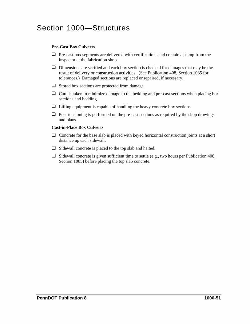
Section 1000—Structures
Pre-Cast Box Culverts
Pre-cast box segments are delivered with certifications and contain a stamp from the inspector at the fabrication shop.
Dimensions are verified and each box section is checked for damages that may be the result of delivery or construction activities. (See Publication 408, Section 1085 for tolerances.) Damaged sections are replaced or repaired, if necessary.
Stored box sections are protected from damage.
Care is taken to minimize damage to the bedding and pre-cast sections when placing box sections and bedding.
Lifting equipment is capable of handling the heavy concrete box sections.
Post-tensioning is performed on the pre-cast sections as required by the shop drawings and plans.
Cast-in-Place Box Culverts
Concrete for the base slab is placed with keyed horizontal construction joints at a short distance up each sidewall.
Sidewall concrete is placed to the top slab and halted.
Sidewall concrete is given sufficient time to settle (e.g., two hours per Publication 408, Section 1085) before placing the top slab concrete.
PennDOT Publication 8 1000-51
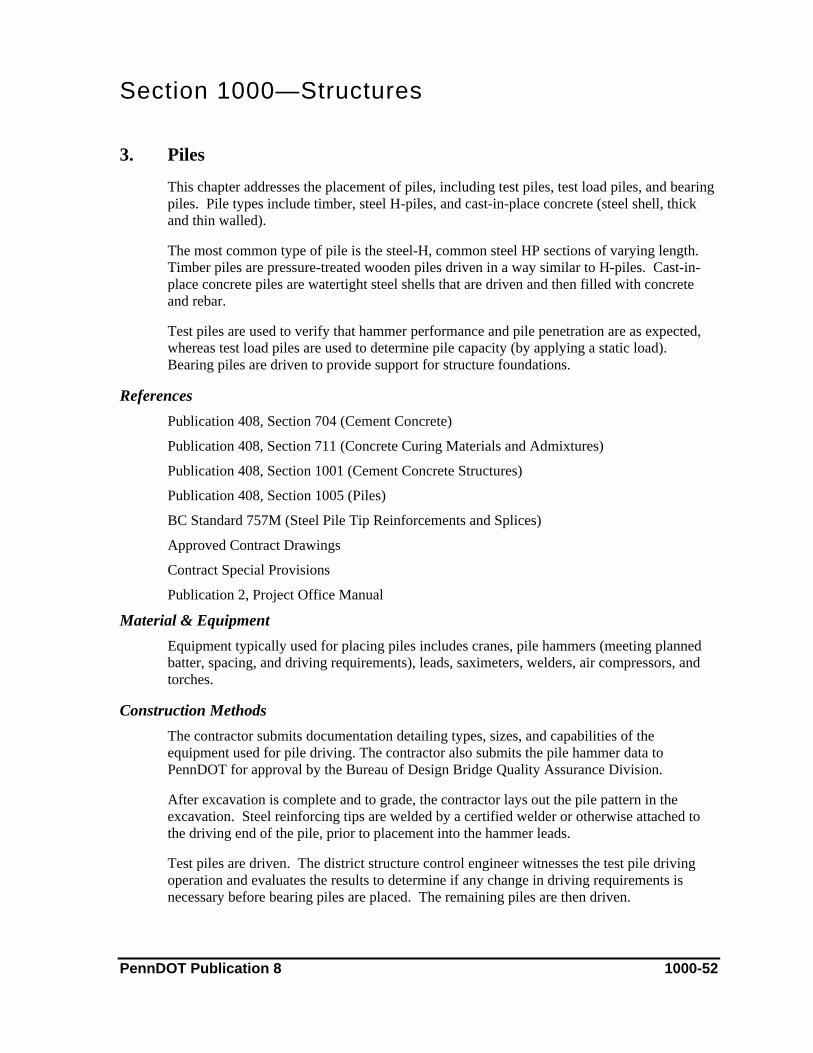
Section 1000—Structures 3. Piles
This chapter addresses the placement of piles, including test piles, test load piles, and bearing piles. Pile types include timber, steel H-piles, and cast-in-place concrete (steel shell, thick and thin walled).
The most common type of pile is the steel-H, common steel HP sections of varying length. Timber piles are pressure-treated wooden piles driven in a way similar to H-piles. Cast-in-place concrete piles are watertight steel shells that are driven and then filled with concrete and rebar.
Test piles are used to verify that hammer performance and pile penetration are as expected, whereas test load piles are used to determine pile capacity (by applying a static load). Bearing piles are driven to provide support for structure foundations.
References Publication 408, Section 704 (Cement Concrete)
Publication 408, Section 711 (Concrete Curing Materials and Admixtures)
Publication 408, Section 1001 (Cement Concrete Structures)
Publication 408, Section 1005 (Piles)
BC Standard 757M (Steel Pile Tip Reinforcements and Splices)
Approved Contract Drawings
Contract Special Provisions
Publication 2, Project Office Manual
Material & Equipment Equipment typically used for placing piles includes cranes, pile hammers (meeting planned batter, spacing, and driving requirements), leads, saximeters, welders, air compressors, and torches.
Construction Methods The contractor submits documentation detailing types, sizes, and capabilities of the equipment used for pile driving. The contractor also submits the pile hammer data to PennDOT for approval by the Bureau of Design Bridge Quality Assurance Division.
After excavation is complete and to grade, the contractor lays out the pile pattern in the excavation. Steel reinforcing tips are welded by a certified welder or otherwise attached to the driving end of the pile, prior to placement into the hammer leads.
Test piles are driven. The district structure control engineer witnesses the test pile driving operation and evaluates the results to determine if any change in driving requirements is necessary before bearing piles are placed. The remaining piles are then driven.
PennDOT Publication 8 1000-52
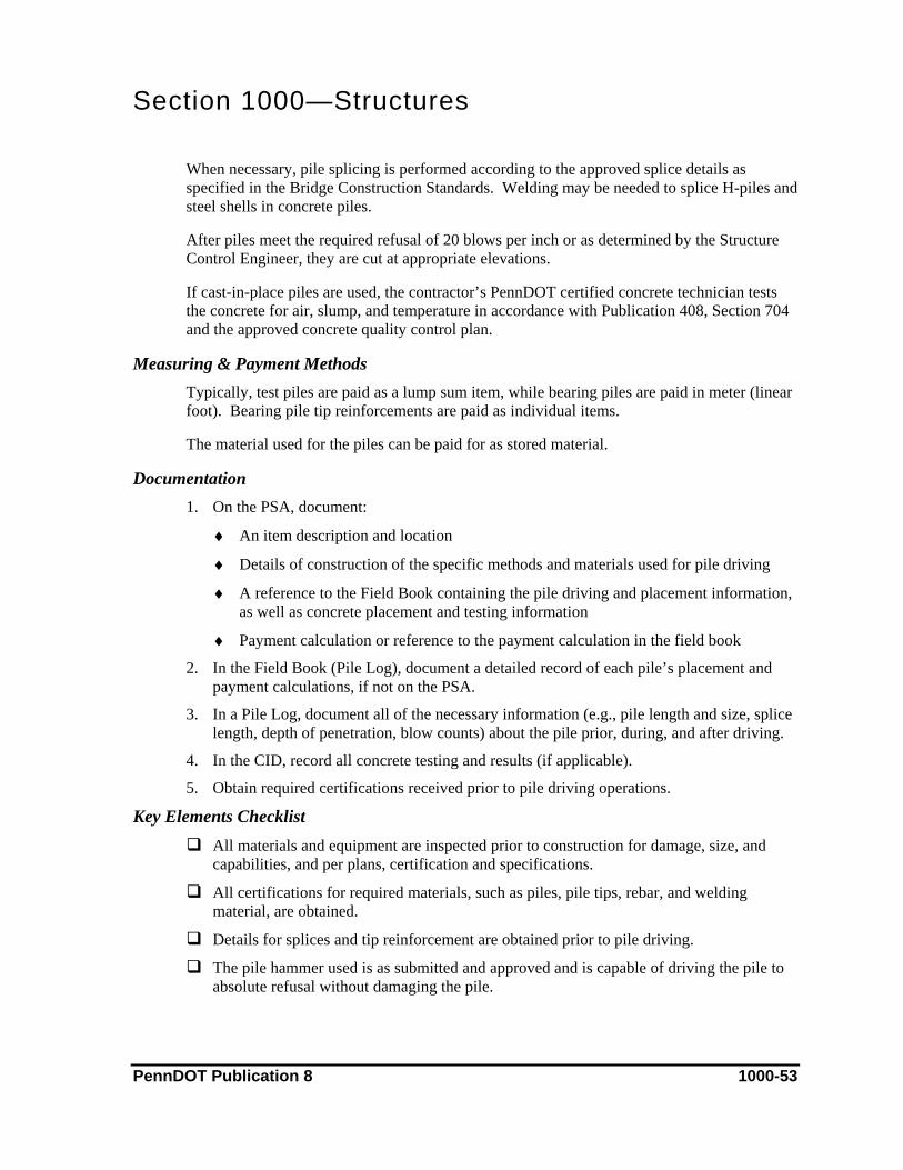
Section 1000—Structures
When necessary, pile splicing is performed according to the approved splice details as specified in the Bridge Construction Standards. Welding may be needed to splice H-piles and steel shells in concrete piles.
After piles meet the required refusal of 20 blows per inch or as determined by the Structure Control Engineer, they are cut at appropriate elevations.
If cast-in-place piles are used, the contractor’s PennDOT certified concrete technician tests the concrete for air, slump, and temperature in accordance with Publication 408, Section 704 and the approved concrete quality control plan.
Measuring & Payment Methods Typically, test piles are paid as a lump sum item, while bearing piles are paid in meter (linear foot). Bearing pile tip reinforcements are paid as individual items.
The material used for the piles can be paid for as stored material.
Documentation 1. On the PSA, document:
♦ An item description and location
♦ Details of construction of the specific methods and materials used for pile driving
♦ A reference to the Field Book containing the pile driving and placement information, as well as concrete placement and testing information
♦ Payment calculation or reference to the payment calculation in the field book
2. In the Field Book (Pile Log), document a detailed record of each pile’s placement and payment calculations, if not on the PSA.
3. In a Pile Log, document all of the necessary information (e.g., pile length and size, splice length, depth of penetration, blow counts) about the pile prior, during, and after driving.
4. In the CID, record all concrete testing and results (if applicable).
5. Obtain required certifications received prior to pile driving operations.
Key Elements Checklist All materials and equipment are inspected prior to construction for damage, size, and
capabilities, and per plans, certification and specifications.
All certifications for required materials, such as piles, pile tips, rebar, and welding material, are obtained.
Details for splices and tip reinforcement are obtained prior to pile driving.
The pile hammer used is as submitted and approved and is capable of driving the pile to absolute refusal without damaging the pile.
PennDOT Publication 8 1000-53
Section 1000—Structures
Pile hammer driving heads are capable of holding the top of the pile in the correct position while distributing the force of the blows over the entire area.
A certified welder performs all welding.
Core borings are checked for changes in the penetration of the pile.
Excavation is complete prior to pile driving, unless permitted by the district structure control engineer.
Hammer drop and blow count are closely monitored during the entire pile driving operation to verify that the desired pile bearing resistance is achieved without over-driving or damaging the pile.
Piles are marked in m or mm (foot or inch) increments as required so the inspector can easily determine refusal and payment length.
When using a saximeter (a device that counts hammer blows automatically), the correct hammer and pile variables for accurate meter operation are loaded.
Piles are oriented, battered, and located per plans prior to driving.
Piles are driven to absolute refusal (as determined by the district structure control engineer) from driving the test piles and pile load tests. (Refer to the minimum driving requirements for refusal in Publication 408, Section 1005).
The same hammer, using the same procedures, is used to drive bearing piles as to drive test piles.
Piles raised by the driving of adjacent piles are re-driven to refusal.
Piles are located and battered according to the structure plans and within the tolerances noted in Publication 408, Section 1005.
The district structure control engineer approves piles that attain absolute refusal prior to reaching predetermined elevations.
Water jets are not used for embankment areas.
The required distance is maintained from uncured concrete to the pile driving operation, as noted in Publication 408, Section 1005.
After driving, piles are cut to the elevation specified in the structure plans.
Timber Piles
Prior to placement, timber piles are inspected for soundness, straightness, size, and agreement with received certifications.
Piles are clean-peeled and pressure treated prior to use.
Pile tips and butts are squared before driving.
Pile tip reinforcements are approved and attached firmly.
Close attention is paid to timber piles during driving. Damaged piles are replaced.
PennDOT Publication 8 1000-54
Section 1000—Structures
Brooming of timber piles is not accepted.
Cast-in-Place Concrete Piles
Steel shells are of the type and size as indicated by the certifications, structure plans, and Publication 408, Section 1005, and are water tight.
End closure and splice details are obtained prior to driving.
Steel shells withstand driving forces without failure and support surrounding material after the driving. Corrosion or damage of the steel shell is not severe enough to compromise the shell’s structural integrity. Damaged shells are replaced.
Driven shells are inspected using a light on a cord long enough to reach the bottom of the shell.
Water and debris is removed from driven shells prior to concrete placement.
Welding of shell splices is as approved.
Spliced shells meet the required lengths specified in Publication 408, Section 1005.
Testing, placing, curing, and documenting concrete placed in the steel shells is completed as required.
Reinforcement in the concrete is placed as required by the structure plans.
Steel H-Piles
H-piles are of the type and size as indicated by the certifications, structure plans, and Publication 408, Section 1005.
Corrosion or damage of the H-pile is not severe enough to compromise the pile’s structural integrity.
Spliced H-piles meet the required lengths specified in Publication 408, Section 1005.
Welding of H-pile splices is as approved.
PennDOT Publication 8 1000-55

Section 1000—Structures 4. Drilled Caissons
This chapter addresses reinforced cement concrete drilled caisson foundations.
References Publication 408, Section 704 (Cement Concrete)
Publication 408, Section 711 (Concrete Curing Materials and Admixtures)
Publication 408, Section 1002 (Reinforcement Bars)
Publication 408, Section 1006 (Drilled Caissons)
Approved Project Plans
Geotechnical Engineering Report (GER)
Approved Concrete Quality Control Plan
Approved Concrete Mix Design
Material & Equipment Concrete used in the caissons must be supplied from an approved concrete plant and mixed using an approved concrete mix design for the class of concrete indicated.
In excavating, a contractor typically uses a drill rig capable of drilling/augering a hole larger than 750 mm (30 inches) in diameter. Under-reaming tools, special rock augers, core barrels, air tools, and blasting are also used for excavating caissons. Casings or bentonite slurry may be required if caving or ground water is a problem.
Pumps or similar devices may be required for dewatering the excavation. If dewatering cannot be accomplished, an underwater camera may be used for excavation inspections. If dewatering is not a problem, an electric light is used to inspect caisson excavation.
Construction Methods The contractor uses earth augers, under-reaming tools, rock augers, core barrels, air tools, or basting to excavate holes to the correct size and depth. If required, the contractor will bell (enlarge) the bottom of the excavation. If caving, ground water, or unstable rock is encountered during excavation, the contractor may use casing or bentonite slurry to support excavation walls.
After excavating, the contractor dewaters the excavation and places required rebar. Prior to concrete placement, the contractor’s PennDOT certified concrete technician tests the concrete in accordance with the specifications and the approved concrete quality control plan. Concrete is placed using freefall, tremie, or pumping methods, and the contractor may or may not remove the casing during concrete placement. When bentonite slurry is used, it will be displaced and forced upward as the concrete is placed, then roll away from the top of the excavation.
PennDOT Publication 8 1000-56
Section 1000—Structures Measuring & Payment Methods
Shaft sections, rock sockets, casing, test holes, and probe holes are measured and paid in meter (linear foot). Bell footings are paid as an each item.
Documentation 1. On the PSA, document:
♦ An item description and location
♦ Construction details, including which caissons were worked on and what work was performed on each
♦ Reference to caisson logs/inspection reports performed
♦ Payment calculations or references to payment calculations as needed for each payable caisson element
2. Prepare a detailed inspection report for each caisson shaft, with the requirements found in Publication 408, Section 1006.
3. Ensure that concrete is properly documented:
♦ In the CID, document the required information for each load of concrete and the results of testing
♦ Obtain delivery tickets for each load of concrete as it arrives at the project
♦ Prior to concrete placement, obtain an approved concrete quality control plan and approved mix designs
♦ Obtain any other required ACI/PennDOT documents
Key Elements Checklist Test and probe holes are drilled as required.
Depth, location, and orientation of the caissons before, during, and after excavation are as specified in the plans and within the tolerance parameters as noted in Publication 408, Section 1006.
If unstable material or ground water is encountered, shaft casings may be required. Permanent shaft casings may or may not be required.
If required, welding of casing sections are performed by a certified welder.
If approved, bentonite slurry may be used to support shaft walls during excavation.
If approved, blasting may be used for excavation.
Dewatering has been performed with approved methods prior to excavation inspection and concrete placement. Underwater cameras may be required for excavation inspection if dewatering is not possible.
Excavated shafts are inspected and approved prior to concrete placement. Shafts are covered to prevent entry or accidents.
PennDOT Publication 8 1000-57
Section 1000—Structures
Rebar is placed in the drilled caisson shafts per plans and specifications, maintaining proper projections, spacing, and clearances. Approved spacing devices, such as concrete blocks or rebar chairs, are used to maintain rebar position.
Rebar position and excavation cross section are maintained during casing removal and/or concrete placement.
The contractor’s certified concrete technician has tested the concrete in accordance to the specifications and the concrete quality control plan. Test results are within specified limits.
Concrete placement methods have been submitted and approved prior to placement.
Excavation within a distance equal to three diameters of the concrete-filled caissons is prohibited within 24 hours of concrete placement.
A detailed inspection report is submitted for each shaft, per Publication 408, Section 1006.
Load testing is performed, if required by contract documents.
PennDOT Publication 8 1000-58
Section 1000—Structures 5. Mechanically Stabilized Earth (MSE) Walls
This chapter addresses the construction and inspection of mechanically stabilized earth (MSE) walls. MSE walls are retaining walls constructed with concrete face panels, soil stabilizing straps, and aggregate backfill. They are used in areas where retaining the natural slope is not practical due to right-of-way or physical space constraints.
References Publication 408, Section 704 (Cement Concrete)
Publication 408, Section 711 (Concrete Curing Materials and Admixtures)
Publication 408, Section 1001 (Cement Concrete Structures)
BC Standard 799M (Mechanically Stabilized Earth Retaining Walls)
RC Standard 11M (Classification of Earthwork for Structures)
Contract Special Provisions
Approved Structure Plans
Approved Shop Drawings
Approved Concrete Quality Control Plan
Approved Concrete Mix Designs
Material & Equipment Class A concrete is used for panel and barrier leveling pads, while Class AA concrete is used for monument slabs and cast-in-pace barriers. The concrete used must be supplied by an approved concrete plant and mixed using an approved mix design for the class indicated.
When cast-in-place barriers are not used, pre-cast barriers must be placed on top of the panels. Pre-cast barriers are used as the traffic barrier when the roadway is completed.
Backfill consists of No. 57 aggregate, MSE aggregate, embankment fill, and other approved aggregate fill as required. Concrete face panels are used as the visible face of the wall and to hold backfill stabilizing straps and concrete barriers in place. Stabilizing straps are steel straps or mesh connected to the back of the panels and embedded in the MSE backfill. They serve to create the binding force that gives the wall its strength.
An impervious membrane is placed on top of the MSE backfill to prevent water infiltration into the backfill. Perforated drainpipe is used in conjunction with the membrane to drain water. Class 2 geotextile is used to separate the embankment material and the aggregate backfill, as well as to contain aggregate around weep holes, drain pipes, and panel joints.
The contractor uses a combination of equipment, including a track hoe, crane, and bulldozer for excavation and for placing panels, backfill, and concrete. A roller is used for compacting backfill material, and a vibratory plate used for light compaction near the panels.
PennDOT Publication 8 1000-59

Section 1000—Structures Construction Methods
The wall area is excavated as required and the subgrade is compacted to the required density and elevation. A specified granular fill material is placed on the subgrade to the top of the leveling pad excavation. A leveling pad is then formed and placed. The contractor will survey a line for the bottom row of panels on the leveling pad.
The first row of panels is placed using clamps and bracing to stabilize the panels until the backfill and stabilization straps are placed. MSE backfill, panels, straps, and embankment fill are placed concurrently according to the plans and shops drawings, and with the required geotextile to the designated elevation. Often, a leveling pad will be required at the top of the final row of panels to create a level surface for barrier placement.
An impervious membrane and drainpipe is placed on top of the MSE backfill to prevent moisture infiltration and to drain water from the wall. A drainage layer of No. 57 aggregate is placed on top of the membrane and then graded. Concrete and rebar for coping, barrier, and moment slabs are placed, according to plans and shop drawings. Roadway plans are used for operations above the drainage layer and/or moment slabs.
Prior to placing concrete, the contractor’s PennDOT certified concrete technician tests the concrete according to the contractors approved concrete quality control plan.
Measuring & Payment Methods MSE walls are paid as a lump sum item, which is broken into an itemized lump sum breakdown format.
Often, the No. 57 aggregate is measured and paid by the cubic meter (cubic yard) as a roadway item. Excavation for MSE walls is typically measured and paid as Class 3 excavation.
Documentation 1. On the PSA, document:
♦ An item description and location
♦ Details of construction, including specific items from the lump sum breakdown and the work performed for each
♦ Reference to materials used, tests performed, and documentation found in other sources (e.g., CID and compaction reports)
♦ Payment calculations or reference to payment calculations as needed for each payable lump sum breakdown element
2. Prepare compaction reports and reference nuclear density reports, non-movement reports (CS-478A), and any other testing required for aggregate and concrete placement.
3. In the Field Book, keep a daily account of each day’s placement for each of the lump sum breakdown activities.
PennDOT Publication 8 1000-60
Section 1000—Structures
4. Ensure that concrete is properly documented:
♦ In the CID, document the required information for each load of concrete and the results of testing
♦ Obtain delivery tickets for each load of concrete as it arrives at the project
♦ Prior to concrete placement, obtain an approved concrete quality control plan and approved mix designs
♦ Obtain any other required ACI/PennDOT documents
5. Obtain required certifications received prior to payment for the MSE walls.
Key Elements Checklist All materials and requirements for the wall have been thoroughly reviewed prior to
construction. This is essential due to variations in wall design and construction methods.
Proper placement, testing, and curing procedures are followed for concrete elements.
If required by the contract special provisions, a representative from the wall fabricator or designer is on-site at the beginning of construction to assist and advise on construction methods.
Subgrade
Excavation or fill operations are performed with the materials specified and to the required dimension set by the plans and shop drawings.
Subgrade is brought to the required elevation and density prior to wall construction.
The district structure control engineer approves subgrade.
Drainage as required by the plans and shop drawings is constructed before backfill operations begin.
Leveling Pad
The contractor surveys the leveling pad to ensure its proper location in accordance with the plans and shop drawings. Correct placement is critical as the wall positioning depends on the leveling pad.
Formwork for the leveling pad is thoroughly checked to ensure minimum required dimensions and level
The contractor’s PennDOT certified technician has tested the concrete in accordance to the specifications and the approved concrete quality control plan. Test results are within specified limits.
The weather conditions conform to specifications.
Concrete Face Panels
Upon arrival at the construction site, panels are inspected for damage and confirmed as the correct item. All panels must have identification markings from the fabricator verifying specifications such as correct designation, dimensions, and strap construction.
PennDOT Publication 8 1000-61

Section 1000—Structures
Panels must have a plant inspector’s stamp verifying that the panel was manufactured per plans and shop drawings. Panels without stamps are not permitted in wall construction.
The contractor positions the bottom row of panels according to the plans and shop drawings. Special care is taken in the placement of each panel, as incorrect placement may have irreversible consequences.
The tops and sides of each panel are checked and corrected, if needed, for level and plumb in their final position.
Panels are battered front and back in a manner to allow for movement (forward push) during backfill. When backfilling is complete, all panel faces are checked for plumb or very near plumb within required tolerances. (Intentionally placed batter is eliminated due to the forward push of the backfill compaction equipment.)
Previously placed panels are checked regularly to ensure expected performance and integrity.
Damaged panels are discarded or repaired using approved repair procedures.
All panel joints are covered with geotextile.
Backfill/Stabilizing Straps
Approved material and placement methods are used for backfill, as required by the plans and shop drawings and the MSE wall designer representative.
Aggregate used for the backfill has been tested and approved by the materials technician.
Close attention is given to backfill compaction and lifts, in providing proper interaction between backfill and stabilizing straps.
Backfill completed by a specified roller is not compacted too forcefully or too close to the face panels, which may result in pushing panels out of plumb.
Compaction near the wall is performed by a vibratory plate or other small compaction equipment. This provides adequate compaction and desired panel movement.
Backfilling of MSE material and embankment fill is completed concurrently, and with the elevation of the materials within required limits.
Stabilization straps are free of damage and of the correct size.
Equipment is not permitted to drive directly on the straps until the backfill is placed on the straps.
The connection between the straps and the panels is performed properly.
Moment Slabs/Barrier/Coping
The correct concrete is used and testing procedures are performed as required for each element according to the plans, shop drawings, and specifications.
Pre-cast elements are inspected for damage and stamps upon delivery.
Rebar is certified and placed per plans and shop drawings.
PennDOT Publication 8 1000-62
Section 1000—Structures
Panels are checked periodically for unwanted movement during forming, concrete placement, and pre-cast placement.
Drainage
Weep holes are in the proper locations and surrounded by geotextile and No. 57 aggregate as required.
The impervious membrane is placed so that overlaps and slope allow all water to flow freely to the drainpipe. Slope is made per plans and shop drawings.
Backfill is placed on the impervious membrane prior to permitting construction traffic to prevent damage to the membrane.
The drainage pipe is placed on the impervious membrane at the correct slope so that drainage to the desired outlet is achieved.
The drainpipe is covered with geotextile prior to No. 57 aggregate placement.
The No. 57 aggregate drainage layer on the membrane is graded and compacted to the planned elevation for roadway material placement.
PennDOT Publication 8 1000-63
Section 1000—Structures 6. Permanent Soldier Pile Walls
This chapter addresses the construction of permanent soldier pile walls.
There are a variety of methods and materials used to build permanent soldier pile walls; therefore, the discussion in this chapter is generalized. For each project, refer to the specific designs, provisions, and specifications required by that particular project.
References Approved Structure Plans
Approved Shop Drawings
Contract Special Provisions
Approved Concrete Quality Control Plan
Approved Concrete Mix Design
Material & Equipment Wood may be used for lagging, bracing, and forms. Construction may also require concrete and related materials, such as grout, slurry, mortar, and shotcrete.
The contractor uses equipment such as cranes, drill rigs, track hoes, loaders, and augers for placing construction materials, including piles, sheeting, studs, forms, concrete, rebar, and tie backs. Tensioning anchorage systems may require the use of hydraulic jacks. Pumps and other devices may be used for dewatering.
Construction Methods The contractor submits shop drawings for approval prior to construction of the soldier pile wall.
Piles are driven into the ground to the required depths, using a pile hammer or an auger. The drilled shafts containing the piles may be filled with concrete, aggregate, or another material as required by the shop drawings.
Excavation is performed adjacent to the piles. Concurrent to excavation, lagging may be placed between the piles, or secured with studs welded to the front face of the piles. Other necessary anchorage systems (such as ground anchors) are also installed during excavation.
When excavation is complete, facing material, with any required reinforcement, is constructed according to the shop drawings. After facing is complete, a protective coating is applied, if applicable.
Drainage is installed at various stages of the wall construction, as required by the shop drawings.
Measuring & Payment Methods Soldier pile walls are usually paid as a lump sum item.
PennDOT Publication 8 1000-64
Section 1000—Structures Documentation
1. On the PSA, document:
♦ An item description and location
♦ Details of construction of the specific methods and materials used for the particular soldier pile wall
♦ Reference to the Field Book and CID, if applicable
♦ A pay quantity calculation or reference to a pay calculation for that day’s activities, if applicable
2. In the Field Book, record sketches, testing and any other required information.
3. In the CID, document the required information for concrete used and the results of testing
4. Obtain other required documentation:
♦ Contractor designed, submitted, and approved shop drawings (prior to excavation support construction)
♦ Approved mix designs
♦ Material certifications
♦ Other required ACI/PennDOT documents
Key Elements Checklist Due to the numerous safety issues associated with large excavations, all work is done in
strict compliance to contract and shop drawings
Certifications are obtained for materials, such as wood, steel, welding equipment, grout, and concrete, prior to their use in the wall.
The contractor has the required experience, per the special provisions.
Welders are certified to perform welding operations.
Materials are inspected for damage and compliance with the certifications and design prior to their use.
Restrictions on excavation depth permitted are understood prior to placing the initial or additional excavation support. Support systems are placed concurrent to excavation.
Soldier piles are installed to the required design depth to allow for safe and proper wall construction.
Post-tensioning and pull testing is performed on anchors, as required by Publication 408, Section 1108 and the shop drawings.
Space between the lagging and the excavated earth face is kept to a minimum. If necessary, fill is placed behind installed lagging to eliminate earth movement or failure (sudden earth movements or failures in this area may overcome the strength of the lagging).
PennDOT Publication 8 1000-65
Section 1000—Structures
All testing, placement, and curing of concrete and grout is performed and documented as required.
Rebar (if applicable) is placed as required by the shop drawings and Publication 408, Section 1002.
Close attention is given to the tie-in of the wall facing the soldier piles. The tie-in allows the piles and the facing to act compositely, evenly distributing the load from the piles to the facing. (This scenario is similar to that of bridge beams tying into a deck slab.)
Proper, approved measures are taken to adequately dewater excavations.
Drainage is installed at the proper location in the wall construction.
Fences, barriers or other approved methods are used to safely isolate the excavation.
Facing has architectural treatment and protective material (e.g., anti-graffiti, sealers, paint) as required by shop drawings.
PennDOT Publication 8 1000-66
Section 1000—Structures 7. Sound Barriers
This chapter addresses sound barriers used to reduce highway traffic noise for nearby residents. The most common type of sound barrier comprises a series of posts at specified spacing with either ground-mounted or surface-mounted panels placed between.
References Publication 408, Section 704 (Cement Concrete)
Publication 408, Section 705 (Joint Material)
Publication 408, Section 711 (Concrete Curing Materials and Admixtures)
Publication 408, Section 714 (Precast Concrete Products)
Publication 408, Section 1001 (Cement Concrete Structures)
Publication 408, Section 1002 (Reinforcement Bars)
Publication 408, Section 1006 (Drilled Caissons)
Publication 408, Section 1019 (Protective Coating For Reinforced Concrete Surfaces)
Publication 408, Section 1031 (Timber Structures)
Publication 408, Section 1086 (Sound Barriers)
BC Standard 776M (Ground Mounted Sound Barriers—Precast Concrete Panels)
BC Standard 777M (Ground Mounted Sound Barriers—Precast Concrete Posts)
BC Standard 778M (Ground Mounted Sound Barriers—Steel Posts)
BC Standard 779M (Structure Mounted Sound Barrier Walls)
BC Standard 780M (Offset Sound Barrier Walls)
Approved Contract Drawings
Approved Shop Drawings
Contract Special Provisions
Approved Concrete Quality Control Plan
Approved Concrete Mix Design
Material & Equipment Wall foundations comprise reinforced concrete caissons or reinforced concrete spread footings, while wall panels consist of pre-cast reinforced concrete or timber panels. Posts may be pre-cast reinforced concrete, steel H-beams, steel pipe post, or timber. Neoprene bearing pads are used for seating panels on the foundations.
Color matching non-shrink grout is required for holes resulting from lifting inserts and patching. An anti-graffiti compound or stain may be applied to the wall faces.
PennDOT Publication 8 1000-67

Section 1000—Structures
Surveying equipment is used to maintain the correct elevations of foundations, panels, and posts. Equipment for testing, placing, and curing concrete is required for foundation placement, and lifting equipment, including cranes, track-hoes, and loaders, is required for concrete, post and panel placement. Bracing is used to hold the posts in the correct position during concrete. Welding equipment may be required for some steel applications.
Construction Methods The contractor must submit a set of construction shop drawings and a concrete quality control plan for approval prior to construction of the sound barrier.
A reinforced concrete foundation of either drilled caissons or spread footings is placed to the required grade (as set by the contractor’s surveyors). The contractor’s PennDOT certified concrete technician tests the concrete in accordance with the specifications and the approved concrete quality control plan. The posts or post base plates are embedded into the foundation during foundation concrete placement. For structure mounted sound barriers, the post base plates may be incorporated into the structure.
If the panels are ground mounted, the contractor grades the area between the posts as required to allow proper panel placement. Pre-cast panels will then be placed between the posts.
All lifting devices are removed or patched as required. If necessary, anti-graffiti compound or stain is then applied.
Measuring & Payment Methods Wall posts are paid as an each item while wall panels are paid in square meter (square foot). Anti-graffiti compound, stain, caissons, and other construction materials are paid as specified in the special provisions and contract drawings.
Documentation 1. On the PSA, document:
♦ An item description and location
♦ Details of construction including particular methods and materials used for barrier construction that day
♦ Reference to Field Book and CID, if applicable used for logging materials, measuring materials, testing, or making payments
♦ Payment for the day’s barrier construction, if required
2. In the Field Book, document:
♦ A detailed record of rebar placed
♦ A list of placed foundations, panels, posts, and other items to keep track of previous placement and payment
♦ The results of the required testing for subgrade/subbase used for barrier construction
PennDOT Publication 8 1000-68

Section 1000—Structures
3. A detailed inspection report for each caisson shaft as required by contract drawings, special provisions, and Publication 408, Section 1006. When applicable, perform and record the required testing for subgrade/subbase used for barrier construction.
4. In the CID, document the required information for concrete used and the results of testing.
5. Obtain other required documentation:
♦ Contractor designed, submitted, and approved shop drawings (prior to excavation support construction)
♦ Approved concrete mix designs
♦ Material certifications
♦ Other ACI/PennDOT required documentation
Key Elements Checklist Approved sound barrier shop drawings and all applicable certifications are obtained prior
to barrier construction.
The contractor’s certified concrete technician has tested the concrete in accordance to the specifications and the approved concrete quality control plan. Test results are within the required specification limits.
The weather conditions conform to specifications.
Caisson or footing top and bottom elevations are checked according to the shop drawings.
The tops of footings or caissons where the panels sit are constructed smooth or ground smooth per tolerances provided in Publication 408, Section 1086.
The depth of projection of the posts or anchor bolts into the wall foundation is per shop drawings.
Posts and panels conform to the vertical and horizontal erection tolerances outlined in Publication 408, Section 1086.
Steel posts are epoxy coated. Damage to the coating is repaired using approved methods.
For ground mounted panels, grade and test subbase/subgrade material is placed between posts as required.
Panels are transported, handled, and stored in the upright position only, never flat on their side.
All joints are light tight to prevent direct sound transmission.
Panels are placed between the posts to provide vibration-free installation.
Open joints are sealed with a caulking compound the same color as the panels.
An approved non-shrink grout is used under post base plates and to fill lifting insert holes.
PennDOT Publication 8 1000-69

Section 1000—Structures
Elastometric pads, joint seals, and backer rods are inserted as required between the panels and the posts.
Approved anti-graffiti coating or stain is applied to the wall as detailed in the contract drawings.
Items such as doors, fire hydrants, and lighting that may effect the construction of the sound barrier are considered.
PennDOT Publication 8 1000-70

Section 1000—Structures 8. Temporary Excavation Support System
This chapter addresses temporary support and protection systems. There are a variety of methods and materials used to build temporary excavation support systems; therefore, the discussion in this chapter is generalized.
It’s required that temporary excavation support systems be designed by a professional engineer registered in the State of Pennsylvania hired by the contractor. For each project, refer to the specific designs, provisions, and specifications required by that particular project.
References Approved Structure Plans
Approved Shop Drawings
Contract Special Provisions
Approved Concrete Quality Control Plan
Approved Concrete Mix Design
Material & Equipment Construction materials include steel rebar, tie backs, piles, sheeting, and studs. Wood may be used for lagging and bracing. Construction of some support systems may also require concrete and related materials, such as grout, slurry, mortar, and shotcrete. Tensioning may require the use of hydraulic jacks.
Equipment used for excavation includes drill rigs, track hoes, loaders, augers, and trenchers, as well as safety systems.
Pumps and other devices may be used for dewatering
Construction Methods The contractor submits contractor-designed shop drawings for approval prior to construction of any type of excavation support system. If required, the contractor’s PennDOT certified concrete technician tests concrete as per the approved concrete quality control plan
Excavation support systems may incorporate sheet piles, soldier pile and lagging, soil nails, micro/mini piles, pressure grouting, slurry walls, tieback anchors, deadman anchors, and underpinning.
Sheet piles are a series of interlocking steel shell piles driven into the earth with a vibratory hammer to specified depth of the approved drawings. This allows excavation to be performed adjacent to the sheets. Sheet piles are often the system used for excavations near buildings, structures, and cofferdams. They provide a neat vertical face with minimal disturbance to surrounding areas.
In the soldier pile and lagging method, piles are driven into the ground to required depths using a pile hammer. Excavation is performed adjacent to the piles, by placing wood lagging
PennDOT Publication 8 1000-71

Section 1000—Structures
behind the flanges of the piles or by attaching the lagging to the outside of the flanges with welded studs, concurrent to excavation. This is the most common method used for large excavations.
The soil nail system incorporates a series of closely placed steel tendons (nails) placed into the face of an excavation and given a shotcrete face. This method of support is good for sandy soils and small working areas.
Micro/mini piles are made by drilling small shafts (mini = 150 mm to 300 mm [6 inches to 12 inches]; micro = 50 mm to 125 mm [2 inches to 5 inches]) deep into bedrock, creating rock sockets. Reinforcing steel is then placed and grout is pumped into the shaft. This method works particularly well when there are overhead restrictions.
The pressure grouting method uses pressure to inject grout into voids, cracks, and cavities to stabilize the ground for adjacent excavation or other construction activities.
Slurry walls use a slurry material (bentonite) to stabilize excavation walls while excavation equipment removes the material beneath the slurry. Slurry remains in the excavation until fill concrete is poured. The concrete displaces the slurry from the excavation. This method is typically used when room for other excavation support systems is problematic.
Tie back anchors are often used in conjunction with other excavation support systems, such as soldier pile walls and sheet piling, to provide extra lateral support. Tie backs comprise shafts with casing drilled deep into the earth, creating a rock socket. Tension steel and pumped grout is then placed in the casing. The casing is then removed and the steel is post tensioned and locked into place. After the grout hardens as required, a pull test on the anchor is performed.
Similar to tie back anchors, deadman anchors are often used to provide lateral support to other excavation support systems. However, this system uses a heavy weight and/or friction (often a large block of concrete or piece of steel buried in the ground) to resist lateral earth forces.
Underpinning is used to stabilize existing structures that have foundations directly adjacent to the excavation. Underpinning extends the support system of a structure to a deeper, more stabile soil stratum.
Measuring & Payment Methods Usually, temporary excavation support system construction is paid as a lump sum item.
Documentation: 1. On the PSA, document:
♦ An item description and location
♦ Details of construction of the specific methods and materials used for the particular excavation support system
PennDOT Publication 8 1000-72
Section 1000—Structures
♦ Reference to the Field Book and CID, if applicable
♦ A pay quantity for that day’s activities if applicable
2. In the Field Book, record sketches, testing, and any other required information.
3. In the CID, document the required information for concrete used and the results of testing.
4. Obtain other required documentation:
♦ Contractor designed, submitted, and approved shop drawings (prior to excavation support construction)
♦ Approved concrete mix designs
♦ Material certifications
♦ Other PennDOT required documentation
Key Elements Checklist Due to the numerous safety issues associated with large excavations, all work is done in
strict compliance to design and approved shop drawings.
Certifications are obtained for all materials, including wood, steel, welding equipment, and grout prior to the material’s use in the support system.
Welders are certified to perform welding operations on excavation support systems.
Materials are inspected for damage and compliance with the certifications and design prior to their use.
Restrictions on excavation depth permitted are understood prior to placing the initial or additional excavation support system. Support systems are placed concurrent to excavation.
Soldier piles are installed to the required design depth to allow for safe and proper wall construction.
Post-tensioning on anchors is performed as required by Publication 408, Section 1108.
Pull tests are performed on anchors, soil nails, and other components as required.
Testing of concrete and grout is performed and documented as required.
Proper, approved measures are taken to adequately dewater excavations.
Fences, barriers, or other approved methods are used to protect people from falling into open excavations.
Excavation support systems are removed as required by the special provisions and/or shop drawings.
Reuse of material from excavation support systems is permitted only as noted in the special provisions and/or the shop drawings.
PennDOT Publication 8 1000-73
Section 1000—Structures 9. End Dams
A. Tooth Expansion Dam with Drain Trough This subchapter addresses installation of a tooth expansion dam with fabric-reinforced drain trough.
References Publication 408, Section 1020 (Tooth Expansion Dam with Drain Trough)
BC Standard 762M (Tooth Expansion Dam for Prestressed Concrete & Steel Beam Bridges)
Contract Special Provisions
Approved Shop Drawings
Deck pouring sequence in plans
Material & Equipment The materials required for this item are listed on the PennDOT-approved shop drawings.
Typical equipment used by the contractor includes cranes, welders, and miscellaneous hand and power tools. Other equipment may be used, as long as the placement is done in accordance with the shop drawings.
Construction Methods The construction of the tooth expansion dam must be completed with strict adherence to the approved shop drawings, BC Standard 762M, and Publication 408 specifications.
Measuring & Payment Methods This item is measured and paid for either in kilograms (pounds) and as part of the structure lump sum. The fabricated expansion dam is eligible for payment under stored materials.
Documentation 1. On the PSA, document:
♦ An item description and location
♦ Field measurements
♦ Payment
2. Obtain certifications for all materials used in seal placement.
Key Elements Checklist The expansion dam has been erected in place and in accordance with the shop drawings
and pouring sequence.
PennDOT Publication 8 1000-74
Section 1000—Structures
The opening dimension of the expansion dam is set based on the air temperature. The opening dimensions for the indicated air temperature are found in the approved shop drawings.
In the set position, the expansion dam matches the roadway grade and cross slope.
Temporary shipping angles have been removed and the plates ground smooth.
Concrete placed under the expansion dam is vibrated until the concrete is forced through the air holes in the dam.
Epoxy bonding compound is placed on transverse blockout joint.
Edges of the expansion dam that are exposed to traffic or pedestrians are ground as specified.
All areas that require painting are completed before the drainage trough is attached to the dam (due to accessibility).
Drainage discharge from the trough ties into the existing drainage system as shown on the contract drawings.
The ends of the drain troughs are watertight.
The depth of the drain trough is set to prevent contact with the substructure.
The drainage trough is installed with stainless steel fasteners.
There is no longitudinal splicing of the drainage trough.
Transverse splicing of the trough is not recommended. However, if it is indicated, splices are vulcanized by the manufacturer.
A certified welder makes all welds in the field. Welder certifications are obtained.
PennDOT Publication 8 1000-75
Section 1000—Structures B. Armored Preformed Neoprene Compression Dam
This subchapter addresses the placement of an armored preformed neoprene compression dam on a bridge. This type of dam is similar to a neoprene strip seal dam except there are no extrusions in the steel armor.
The seal in this type of dam may be shop or field installed.
References Publication 408, Section 1021 (Armored Preformed Neoprene Compression Dam)
BC Standard 766M (Preformed Neoprene Compression Seal Joint for Prestressed Concrete & Steel Bridges)
Contract Special Provisions
Approved Shop Drawings
Deck Pouring Sequence
Material & Equipment Materials required for this item are listed on the PennDOT-approved shop drawings.
Equipment used to place the dam includes a crane, welder, and various hand and power tools. Other equipment may be used, as long as the placement is done according to the shop drawings.
Construction Methods The contractor sets the dam into place; final adjustments to placement are made later.
Deck rebar is then placed as required and forms for the deck or blockouts are placed at locations shown on the contract drawings. Adjustments to the dam’s final positioning are made and the dam is secured in place with a temporary support assembly as specified in the contract drawings.
After the concrete is placed around the dam and the required concrete strength is achieved, support assemblies are removed from the dam. If not previously installed by the fabricators, the neoprene seal is then placed.
Measuring & Payment Methods This item is measured and paid in either meter (linear foot) or as part of the structure lump sum. Measurements are taken along the seal and include vertical faces.
The fabricated compression dam is eligible for payment under stored material.
PennDOT Publication 8 1000-76
Section 1000—Structures Documentation
1. On the PSA, document:
♦ An item description and location
♦ Details of the day’s construction activities
♦ All field measurements
♦ Payments
2. Obtain certifications for all materials used in seal placement.
Key Elements Checklist A copy of the approved shop drawings is obtained prior to installation.
The shop drawings detail type, size, and all other information required to fabricate and erect the dam.
Shop-installed seals are field adjusted, if required, to width (due to differing temperatures). The opening dimension of the dam is set according to the air temperature and as found on the approved shop drawings.
In the set position, the dam matches the roadway grade and cross slope.
Prior to seal placement, the metal surface is cleaned per Publication 408, Section 1060.
The seal channel is free of concrete and debris.
A lubricating adhesive is placed on the metal grooves and the seal is placed when the adhesive is still wet.
Seals are not spliced unless indicated, and then only those splices vulcanized by the manufacturer are acceptable.
During placement, elongation of the seal beyond 5% is not permitted.
Seals that are twisted or damaged during placement are rejected.
A certified welder completes all welds. A copy of each welder’s certification is obtained.
Epoxy bonding compound placed on transverse blockout joint if blockouts are in the deck pour sequence.
PennDOT Publication 8 1000-77
Section 1000—Structures C. Neoprene Strip Seal Dam
This subchapter addresses the installation of a neoprene strip seal dam.
References Publication 408, Section 1026 (Neoprene Strip Seal Dam)
BC Standard 767M (Neoprene Strip Seal Dam for Prestressed Concrete & Steel Beam Bridges)
Contract Special Provisions
Approved Shop Drawings
Deck Pouring Sequence
Material & Equipment The equipment used by contractors for the placement of the expansion dam will vary, and may include cranes, welders, and miscellaneous hand and power tools. Other equipment may be used, as long as the placement is done in accordance with the shop drawings.
Construction Methods Commonly, the expansion dam is set in place prior to deck placement, with final adjustments to the exact location made later in the process. Deck rebar is placed as required. Blockouts are formed at the locations shown in the contract drawings and deck concrete is placed up to the blockouts.
Final adjustments are made to the expansion dam and it is then secured in place with a temporary support assembly as shown in the joint installation scheme on BC Standard 767M or by other approved methods. Concrete is placed in the blockouts around the expansion dam and after the required concrete strength is achieved, the support assembly is removed from the dam. Touch-up painting is done, if necessary.
The strip seal is then installed, per the installation notes on BC Standard 767M.
Measuring & Payment Methods This item is measured and paid for as either a meter (linear foot) item or as part of the structure lump sum. The fabricated expansion is eligible for payment under stored material.
Documentation 1. On the PSA, document:
♦ An item description and location
♦ Details of the day’s construction activities related to this activity
♦ All field measurements
♦ Payment record
PennDOT Publication 8 1000-78
Section 1000—Structures
2. Obtain certifications for all materials used in seal placement.
Key Elements Checklist A copy of the approved shop drawings is on file.
The expansion dam has been erected in place and in accordance with the approved shop drawings and deck pour sequence.
Epoxy bonding compound placed on transverse blockout joint.
The opening dimension of the expansion dam is set based on the air temperature, as noted on the approved shop drawings.
In the set position, the expansion dam matches the roadway grade and cross slope.
Temporary shipping angles have been removed and the plates have been ground smooth.
The seal channels are free of concrete and debris.
The installed seal is not cocked or twisted.
If stretching of the seal during installation is unavoidable, elongation of the seal does not exceed 5%.
Damaged seals are removed or replaced.
Seals are not spliced unless indicated, and then only those splices vulcanized by the manufacturer are acceptable.
A certified welder completes all welds. A copy of the welders’ certification is obtained.
Touch-up painting on the expansion dam, if necessary, is completed.
PennDOT Publication 8 1000-79

Section 1000—Structures 10. Preformed Neoprene Compression Joint Seals for Bridges
This chapter addresses the installation of preformed neoprene compression joint seals in bridges.
References Publication 408, Section 705 (Joint Material)
Publication 408, Section 1008 (Preformed Neoprene Compressive Joint Seal for Bridges)
BC Standard 766M (Preformed Neoprene Compression Seal Joint for Prestressed Concrete & Steel Bridges)
Bulletin 15, Approved Construction Materials
Approved Contract Drawings
Contract Special Provisions
Deck Pour Sequence
Material & Equipment The materials for this item include neoprene seal, lubricant adhesive, premolded expansion joint filler, and foam joint fillers. Check the materials for defects (e.g., damage to the sealers and joint fillers or frozen lubricant adhesive).
Equipment used to apply seals includes various hand tools and concrete saws.
Construction Methods Joint seals are typically constructed using one of two methods:
1. The joint is formed with foam joint filler and the concrete is placed. If the joint is not formed, the contractor will sawcut the joint.
2. The seal grove is sawcut, debris is removed from the joint, and the joint is dried, if necessary. Adhesive lubricant is applied and the seal is placed in the joint.
Measuring & Payment Methods Payment for this item is typically made by the meter (linear foot) or as part of the structure’s lump sum. These materials are usually not paid for as stored materials.
Documentation 1. On the PSA, document:
♦ An item description and location
♦ Field measurements
♦ Payment calculations
2. Obtain certifications for all materials used in seal placement.
PennDOT Publication 8 1000-80
Section 1000—Structures Key Elements Checklist
The joint is properly located.
Sawcuts have a minimal spalling effect on the concrete edges along the length of the joint.
The lubricant adhesive is applied uniformly.
The seal is installed properly; it is free of twists and if stretching was required, it does not exceed 5% elongation.
PennDOT Publication 8 1000-81
Section 1000—Structures 11. Structural Backfill
This chapter addresses the placement of structural backfill.
References Publication 408, Section 703 (Aggregate)
Publication 408, Section 1001 (Cement Concrete Structures)
RC Standard 12M (Backfill at Structures)
Approved Structure Plans
Material & Equipment Most structural backfill material is AASHTO No. 57 aggregate; AASHTO No. 1 stone can also be used. The aggregate used for backfill is one of the types listed on RC Standard 12M; plan documents sometimes specify the type of aggregate to be used. If the plan documents do not specify the type of aggregate, the contractor chooses one from RC Standard 12M.
Equipment used for structural backfill includes track hoes, rollers, gradealls, bulldozers, front-end loaders, vibratory plates, and other earth moving, excavating, and compaction equipment. Equipment used must have the capacity to meet the requirements for placement and compaction set by the plans and specifications.
Construction Methods After excavation and structure placement is complete, the contractor places geotextile and waterproofing/drainage as needed in the area to be backfilled. Backfill material is placed using lifts; each lift is then compacted. Material for weep holes, such as geotextile and No. 57 aggregate, is placed as required.
Backfill continues until the desired elevation is achieved. If applicable, the backfill is covered with a layer of geotextile to separate the backfill material from adjoining or layered fills (e.g., roadway subbase).
Measuring & Payment Methods Structural backfill is measured and paid as part of the lump sum bridge item, or in cubic meter (cubic yard) or by the tonne (ton). Geotextile material is considered incidental to structural backfill.
Documentation 1. On the PSA, document:
♦ An item description and location
♦ Details of construction of the specific elements backfilled and the progression of fill placement for that day
PennDOT Publication 8 1000-82
Section 1000—Structures
♦ Reference to compaction reports
♦ Payment calculation
2. In the Field Book, document daily placements and payments, if applicable.
3. Perform and record compaction reports.
4. Obtain delivery tickets for project files, showing types and quantities of materials received.
Key Elements Checklist Geotextile material is used to separate structural backfill material from adjoining
material, such as embankment, excavated earth, and roadway subbase.
All drains, waterproofing, and other embedded materials are placed prior to backfilling.
Materials for weep holes are placed per structure plans, concurrent with backfilling operations.
Excavation performed outside of the required limits is replaced with structural backfill and considered incidental to the excavation.
Structural backfill is placed simultaneous to adjoining embankment.
Symmetric loadings of backfill are maintained when placed adjacent to box culverts, arch rings, and other rigid frame structures.
When backfilling integral abutments, both abutments are backfilled simultaneously with specified elevation tolerances.
Backfill abutments, backwalls, retaining walls, box culverts, or arches cannot be backfilled until seven days after the concrete placement, and then only if compressive strength is achieved.
Backfill is placed and compacted in lifts as required by the specifications. Compaction reports are completed for each lift of backfill.
Compaction equipment is capable of obtaining required compaction.
Material near the rear face of abutments and wings is compacted with a walk-behind vibratory plate in 100 mm (4 inch) lifts, as required by specifications.
PennDOT Publication 8 1000-83

Section 1000—Structures 12. Structural Drainage
A. Downspouting This subchapter covers the installation of downspouting on a bridge structure.
References Publication 408, Section 1051 (Downspouting)
BC Standard 751M (Bridge Drainage)
Shop Drawings
Material & Equipment The material used for downspouting is 200 mm (8 inches) or 250 mm (10 inches) galvanized steel, fiberglass, or PVC Schedule 40 pipe. The pipe should be accompanied by certification and be free of cracks, blemishes, or other damage that may hamper its drainage capability.
Construction Methods The downspouting is connected to the scupper on the underside of the bridge deck. It is fitted, piece by piece, and oriented according to the shop drawings/structure plans. Downspouting is often installed by hand, with the assistance of a man life or man basket.
The downspout outlets to a splash block or storm drain. If splash blocks are used, they should be formed and poured using Class A concrete.
Measuring & Payment Methods Downspouting is measured and paid as part of the lump sum bridge item.
Documentation 1. On the PSA, document:
♦ An item description and location
♦ Daily details of the downspouting placement
♦ Payment calculations as part of the lump sum percentage
2. Obtain certifications delivered with the pipe and fittings/support brackets.
Key Elements Checklist Certifications for pipes, fittings, support braces, and other materials required for placing
downspouting are received prior to downspout construction.
Material received is in compliance with certifications, structure drawings, and shop drawings.
Pipes, fittings, and brackets are placed per structure plans or shop drawings.
PennDOT Publication 8 1000-84
Section 1000—Structures
Splash blocks, where required, are of the correct shape, size, location, and type, according to the structure plan and shop drawings.
Discharges into storm drains, where required, follow roadway/drainage requirements as well as structure plans.
PennDOT Publication 8 1000-85

Section 1000—Structures B. Scuppers
The subchapter addresses the installation of scuppers, drains embedded in a bridge deck to drain water from the deck to a downspout.
Reference BC Standard 751M (Bridge Drainage)
Shop Drawings
Material & Equipment Refer to BC Standard 751M for descriptions of the various types of scuppers. Materials must be accompanied by certifications and be free of cracks, blemishes, or other damage that many hamper their drainage capabilities.
Construction Methods Scuppers are incorporated into the deck formwork prior to concrete placement. Rebar is placed around the scupper as shown in the structure plans and the bridge construction standards.
The scupper is placed to the required deck grade and secured in preparation for concrete placement. After the concrete is placed, downspouting is connected to the scupper.
Measuring & Payment Methods Scuppers are measured and paid as part of the lump sum bridge item.
Documentation 1. On the PSA, document:
♦ An item description and location
♦ Details of construction for that day’s placement
♦ Payment calculations as part of the lump sum percentage
2. Obtain certifications delivered with the scuppers, fittings, and support brackets for the project files.
Key Elements Checklist Material received is in compliance with certifications, structure drawings, and shop
drawings.
Scuppers, fittings, and brackets are placed per structure plans and shop drawings.
Scuppers are set and secured to the proper grade prior to deck concrete placement.
Rebar is placed around the scupper according to structure plans.
PennDOT Publication 8 1000-86

Section 1000—Structures 13. Removal of Existing Bridges or Culverts
This chapter addresses the removal of existing structures or structural elements.
References Publication 408, Section 1018 (Removal of Existing Bridges or Culverts)
Approved Demolition Plans
Approved Traffic Control Plans
Submittals approving the demolition plan from outside agencies (e.g., railroads, gas companies, water and sewer authorities, telephone companies, and local municipalities)
Material and Equipment There is no material list for this item. Equipment used is specified in the approved demolition plans. Verification can be made with submitted catalog cuts for the equipment.
Construction Methods All work must be completed in strict accordance with the approved demolition plans.
Measuring & Payment Methods Payment is typically made as a lump sum item. Progress payments can be made on a scheduled agreed to by the contractor and inspection staff.
Documentation On the PSA, document:
♦ An item description and location
♦ Details of the demolition, including which part of the existing structure was removed during the shift
♦ Payments. If applicable, indicate partial payments made and reference to documentation that may have a schedule of payments
Key Elements Checklist All outside agencies have been notified of the demolition and its schedule. Agencies
have given their approval for the plan and a copy of the approved plan is in the project files.
A PennDOT-approved copy of the demolition plan is on site.
All safety devices (e.g., fences, nets, warning signs) are in place as required.
Traffic patterns for maintenance and protection of traffic are in place according to approved traffic control plans. No work will be performed over live traffic.
Proper equipment and operations and procedures, per the approved demolition plan, are used.
PennDOT Publication 8 1000-87

Section 1000—Structures
Debris removed from the site is disposed in the designated location (e.g., waste areas, fill areas, or off-site location).
At the conclusion of demolition, both daily and at completion, traffic is restored to normal flow (if applicable).
PennDOT Publication 8 1000-88
Section 1000—Structures 14. Concrete Repairs
A. Concrete Bridge Deck Repair This subchapter addresses the removal and patching of deteriorated concrete on a bridge deck to prepare for the placement of a wearing surface.
References Publication 408, Section 704 (Cement Concrete)
Publication 408, Section 711 (Concrete Curing Materials and Admixtures)
Publication 408, Section 1040 (Concrete Bridge Deck Repair)
BC Standard 783M (Reinforced Concrete Repair)
Approved Concrete Quality Control Plan
Approved Concrete Mix Design
Material & Equipment Prior to patching, a concrete bonding compound is applied in the areas to be repaired. Class AAA concrete or wearing surface material is used for patching. The Class AAA concrete used must be from an approved concrete plant and mixed using an approved mix design for the class indicated. Bituminous material used must be supplied by an approved bituminous batch plant and mixed using an approved bituminous mix design for the type of material indicated.
Power-driven hand tools, such as pneumatic hammers, triple-headed tampers, and other mechanical chipping devices may be used in removing deteriorated areas. An approved shielding system to catch falling debris may be required. If concrete is used, the contractor also has suitable testing equipment.
Construction Methods The contractor saw cuts the areas requiring patchwork, then removes the deteriorated concrete using power driven hand tools. Sand or water blasting is used to remove loose chips of concrete on exposed rebar or existing surfaces.
Once the deteriorated concrete is removed, any required rebar and formwork is placed. The contractor’s PennDOT certified concrete technician tests the concrete in accordance with the specifications and the approved concrete quality control plan. The concrete bonding compound is placed, and the area is patched using Class AAA concrete or overlay material as required.
Measuring & Payment Methods This item is measured and paid by the square meter (square foot).
PennDOT Publication 8 1000-89
Section 1000—Structures Documentation
1. On the PSA, document:
♦ An item description and location
♦ Details of construction, including specific locations, dimensions, depths, types of repairs, and materials used
♦ Payment calculation for m2 (square foot) of the patch area
♦ Reference to the CID, if necessary
2. In the CID, document the required information for the concrete used and the results of testing.
3. Obtain other required documentation:
♦ Certifications for the concrete bonding compound and tickets for patching materials.
♦ Approved concrete mix designs
♦ Other ACI/PennDOT required documentation
Key Elements Checklist Repair areas are as indicated by the engineer.
Power-driven hand tools meet the requirements of Publication 408, Section 1040.
Patch areas and exposed rebar are sand or water blasted to remove loose concrete and corrosion. A minimum of 20 mm (3/4 inch) clearance is provided around rebar for proper concrete bonding.
Damaged or heavily corroded rebar is removed and replaced per Publication 408, Section 1002.
Proper shielding, if required, is placed to prevent debris from falling below the deck.
When formwork is required, forms are strong enough to prevent deformation under concrete load. All drip notches and chamfers are included.
The contractor’s PennDOT certified concrete technician has tested the concrete in accordance with the approved concrete quality control plan. Test results are within specified limits.
The weather conditions conform to specifications.
Proper concrete bonding compound is used prior to concrete placement.
Proper curing procedures are used in concrete placement.
Concrete patches placed in advance of overlay have sufficient time to stiffen to prevent deformation under overlay load.
Concrete patches are sand or water blasted prior to placement of overlay to remove laitance.
PennDOT Publication 8 1000-90
Section 1000—Structures B. Scarification
This subchapter addresses the scarification of an existing concrete bridge deck in preparation for placing a wearing surface.
References Publication 408, Section 1041 (Scarification)
BC Standard 783M (Reinforced Concrete Repair)
Material & Equipment Equipment, such as saw cutters, pneumatic hammers, and tampers, conforming to specifications outlined in Publication 408, Section 1041, may be used for areas near parapets and scuppers. A self-propelled scarification machine, meeting the criteria of Publication 408, Section 1041, may be used for the bridge deck. Power brooms and vacuums may be used to remove debris.
Construction Methods The contractor scarifies the area around scuppers and parapets by saw cutting, pneumatic hammer chipping, and/or tampers. A self-propelled scarifying machine is used on the remaining deck. At the end of each day, the contractor removes debris from the work area. This process is performed until the desired depth is reached.
Measuring & Payment Methods This item is measured and paid in square meter (square yard) per each 5 millimeter (1/4 inch) increment of depth.
Documentation On the PSA, document:
♦ An item description and location
♦ Details of construction, including specific areas, depths, and methods of work performed
♦ Payment calculations or reference to payment calculations as needed to the amount of scarification performed
Key Elements Checklist Scarification is done only to the depth and dimensions indicated by the plans or as
directed by the engineer.
Equipment used is in accordance with Publication 408, Section 1041.
Debris is removed and disposed of properly at the end of each workday. Flushing of debris is not permitted.
PennDOT Publication 8 1000-91
Section 1000—Structures C. Epoxy Injection Crack Repairs
This subchapter addresses preparing and sealing cracks in concrete with an epoxy resin mixture. It does not include overhead sealing.
References Publication 408, Section 706 (Concrete Bonding Compound)
Publication 408, Section 1091 (Epoxy Injection Crack Seal)
Bulletin 15, Approved Construction Materials
Manufacturer’s Installation Instructions
Material & Equipment Materials for this item include epoxy resin, surface seal (as recommended by the resin manufacturer), and injection fittings.
To inject cracks, the contractor uses a hand-held injection gun, pressure pot, injection machine, or other method as accepted by the manufacturer, as well as various hand tools.
Construction Methods The inspection staff marks out the area to seal. Surfaces are thoroughly cleaned and any unsound concrete removed. Glue injection ports are placed according to the manufacturer’s recommendations; cracks may need to be beveled in order to place ports. The surface is then sealed along the length of the crack and around the port.
The contractor mixes the epoxy resin system according to the manufacturer’s instructions. Once the surface seal has hardened, the cracks are injected with the sealer, starting at the lowest port and working upward. Once a port is filled, it is plugged and the contractor moves to the next higher port. The operation is complete when the crack is completely filled.
Measuring & Payment Methods This item is paid by the meter (linear foot) or as a predetermined amount. The materials are not paid as stored material.
Documentation 1. On the PSA, document:
♦ An item description and location
♦ Field measurements
♦ Payment
2. Obtain material certifications for all materials used.
Key Elements Checklist The inspection staff has marked out the areas to seal.
PennDOT Publication 8 1000-92
Section 1000—Structures
Surfaces are thoroughly cleaned.
Unsound concrete is removed.
Injection ports are glued into place according to the manufacturer’s recommended spacing.
The surface along the length of the crack and around the port is sealed.
The ambient air and concrete temperature is above 10 °C (50F).
The epoxy resin system is mixed per the manufacturer’s instructions.
The surface seal has sufficiently hardened prior to injection.
Injection proceeds from the lowest port to the highest.
The crack is completely filled.
PennDOT Publication 8 1000-93
Section 1000—Structures D. Pressure Mortar Pointing and Grouting (Guniting)
This subchapter addresses the process of pressure pointing and grouting of concrete, masonry, and steel members. This process is also known as guniting.
Mortar applied under pressure provides a finishing coat for concrete and masonry members and a protective covering for steel members.
References Publication 408, Section 701 (Material)
Publication 408, Section 703 (Aggregate)
Publication 408, Section 720 (Water)
Publication 408, Section 1017 (Pressure Mortar Pointing and Surfacing)
BC Standard 783M (Reinforced Concrete Repair)
Special Provisions
Material & Equipment Materials used include grout, reinforcement, ties, clips, and anchor bolts.
For mortar placement, the contractor uses equipment such as mortar pressure guns, air compressors, heaters, and velocity meters.
Construction Methods The contractor cleans the area to be treated with air, water, sand blasting, hand scraping or similar methods. Reinforcement materials are then placed as required.
Grouting is accomplished by placing one layer of grout at a time using a pressure grout gun. The final main coat is smoothed with hand trowels, given another thin coat of grout, and then, if directed, given a smooth, brushed finish. Treated areas are cured as required.
When applicable, backfill is placed over the treated areas.
Measuring & Payment Methods Surfacing is measured and paid in square meter (square foot). Pointing is measured and paid in meter (linear foot).
Documentation 1. On the PSA, document:
♦ An item description and location
♦ Details of construction, including specific locations, dimensions, materials, and methods used for that day’s placement
♦ Payment calculation for m2 (square foot) or m (linear foot) of grouted area
PennDOT Publication 8 1000-94

Section 1000—Structures
2. Obtain certifications for the materials used, as required.
Key Elements Checklist Work is performed under the supervision of an experienced pressure gun foreperson.
The area to be treated is clean, free of debris, grease, or other foreign material that may prevent effective bonding of the material.
Air and surface temperature are within required tolerances prior to and during mortar placement.
Prior to mortar placement, any reinforcement mesh or rebar used is placed with the proper spacing, laps, and clearances as required.
Only approved materials, such as ties, clips, anchor bolts, and chairs, are used to secure rebar.
More than one layer of reinforcement may be required; however, excessive reinforcement layers that may create a plane of weakness in the treated area are avoided.
Pressure, velocity, and moisture content are uniform during application and are measured with a velocity meter attached to the gun nozzle. Pressure may be increased due to lift and/or length of hose as needed to maintain application parameters.
Mortar is placed as specified (e.g., layer thicknesses, dimensions).
Foreign material trapped by previous mortar layers is removed prior to the application of additional layers.
Areas near treatment sites are protected from rebounding material.
Area is cured as required, following approved concrete curing methods.
Backfill is placed as required, using approved backfill methods.
Make a color sample if in the Special Provisions
Strength samples may be required.
PennDOT Publication 8 1000-95

Section 1000—Structures 15. Latex Modified Mortar or Concrete Wearing Surface
This chapter addresses the placement of a one-course wearing latex modified mortar or concrete wearing surface.
References Publication 408, Section 501 (Rigid Pavement)
Publication 408, Section 701 (Cement)
Publication 408, Section 703 (Aggregate)
Publication 408, Section 704 (Cement Concrete)
Publication 408, Section 711 (Concrete Curing Material and Admixtures)
Publication 408, Section 720 (Water)
Publication 408, Section 1042 (Latex Modified Mortar or Concrete Wearing Surface)
Publication 2, Project Office Manual, Part C, Section 10 (Structures)
PTM 637 (Calibration of Mobile Mixtures Used for Latex Modified Mortar)
Bulletin 15, Approved Construction Materials
Approved Quality Control Plan
Material & Equipment Materials for this work include cement, fine and coarse aggregate, water, and latex emulsion admixture, all in accordance to Publication 408, Section 1042.
The placement of a latex wearing surface involves several operation stages, each requiring specific equipment, including surface preparation equipment, proportioning and mixing equipment, and placing and finishing equipment. Publication 408, Section 1042 details the equipment requirements necessary to successfully complete the placement.
Construction Methods Prior to surface placement, the quality control plan must be approved and all equipment must be accepted for use.
The contractor begins preparing the deck by removing all loose concrete and making necessary repairs to the concrete. Rebar is cleaned of rust and corrosion. Within a seven day period prior to placement, the deck is scarified. Twenty-four hours prior to placement, the deck is thoroughly cleaned and the surface covered to prevent contamination. At least one hour prior to placement, the deck is thoroughly soaked with water.
Before latex placement, all mixing units are calibrated in the presence of the inspection staff and the contractor’s PennDOT certified concrete technician performs any required testing. During placement, the grout from the mixture is scrubbed into the surfaces to be overlayed with latex concrete. Aggregate from the grout application is removed from the deck and discarded.
PennDOT Publication 8 1000-96

Section 1000—Structures
Latex concrete is placed and finished with a finishing machine per the approved procedures. Texturing is then completed, unless mechanical texturing is specified; if so, a five day waiting period is required before texturing can occur. Lastly, curing is applied and the deck is retested and resounded as directed.
Measurement & Payment Methods This item is paid by square meters (square yards) or as part of the lump sum.
Documentation On the PSA, document:
♦ An item description and location
♦ Field measurements made
♦ Calibration of mixers
♦ Payment
Key Elements Checklist All equipment for the latex wearing surface work is accepted by PennDOT prior to
commencing work. The equipment meets the requirements outlined in Publication 408, Section 1042.
During surface preparation, all rust and corrosion on rebar is removed. All unsound concrete is removed and necessary repairs are made to the concrete surface being overlaid.
Within seven days of placement, the deck surface is scarified.
Within 24 hours of placement, all surfaces to be overlaid are cleaned by an approved method and covered to prevent contamination.
Prior to placement, the surface to be overlaid is watered for at least one hour to ensure that the deck is thoroughly saturated.
Proportioning and mixing equipment has the capacity to deliver a specified minimum quantity per hour as listed in Publication 408, Section 1042.
The mixing truck has separate covered compartments for each ingredient of the latex modified mortar concrete.
The feed system on the mixer truck delivers all ingredients to the mixer unit at the specified rate.
The mixing unit produces latex of uniform consistency and without segregation.
Prior to latex placement, each mixing unit is calibrated in the presence of the inspection staff.
Mixing units are recalibrated after a specified amount of latex is placed.
Aggregate is used within 12 hours of being loaded into the mixing unit.
PennDOT Publication 8 1000-97
Section 1000—Structures
If conditions cause a variable moisture content change in the aggregate, (e.g., rain, winds), the mixing unit bins are emptied and refilled with new aggregate.
The latex grout is scrubbed on all surfaces to be overlaid. Excess aggregate from brushing is removed and discarded.
The grout cannot dry before the overlay material is placed.
Perform testing as per the QC plan and Publication 408, Section 1042.
Heavy equipment and vehicular traffic are not permitted on the latex surface until the specified time and strength have been met as per Publication 408, Section 1042.
Curing is applied to the surface as soon as possible without marking the fresh latex.
Mechanical texturing is not applied until five days after placement.
The hardened latex is tested per Publication 408, Section 501.
The deck is resounded if directed by the district structure control engineer.
Membrane forming and monomolecular compounds are not used for curing. Curing procedures follow specifications in Publication 408, Section 1001.
Publication 408, Section 1042 is referenced for limitations of operations.
PennDOT Publication 8 1000-98

Section 1000—Structures 16. Timber Structures
This chapter addresses the construction of timber structures. Timber can be used in substructures and superstructures, constructed as indicated in the contract drawings. Timber substructures include bent piles, framed bents, bearing sill caps, and bracing. Timber superstructures include stringers, wheel guards, rails, parapets, and decks.
References Publication 408, Section 1031 (Timber Structures)
Contract Special Provisions
Approved Shop Drawings
Material & Equipment Timber specifications are found in Publication 408. Structures are constructed of select structural, No. 1 or No. 2 grade lumber or timber. Treated lumber and timber products must have permanent symbol imprints or documentation that identify the treating company, treating type, treatment year, and certification of conformance with the American Wood Preservers Association.
Tolerances for width, depth, length, squareness, and beam camber are indicated in Publication 408, Section 1031.
The contractor uses a variety of power and hand tools in timber construction, as well as lifting equipment (e.g. cranes, track hoes, man-lifts) to handle larger timber members.
Construction Methods The timber must be stored and handle in a manner that prevents damage. Corner protection must be provided for banded material.
In general, all timber cuts should accurate, achieving close fit to providing even bearing of joints over the entire contact surface. Bored holes should be appropriately treated, and holes and plugs filled with treated plugs. Connectors must be installed as specified in Publication 408, Section 1031. Washers must be used under all nuts and bolt heads that would otherwise come in contact with wood and all nuts should be locked after final tightening.
The contractor should pressure treat timber surfaces embedded in concrete or earth, or those in contact with soil, as specified in Publication 408, Section 1031. Timber treated with oil-borne preservatives cannot be painted.
If the treated timber will come into contact with humans, an acceptable two-coat sealer must be applied to the timber. Treated timber that is cut or bored must be treated with an acceptable wood preservative at the location of the cut or bore.
When a bituminous wearing surface is to be placed over timber decking, excretions and surface residue deposits must be cleaned from the surface prior to placing the wearing surface. A blotter material, consisting of sandy silt, is spread over the timber deck and then
PennDOT Publication 8 1000-99
Section 1000—Structures
broomed off. This process is repeated until all excretions are removed. The contractor may construct a waterproofing membrane and provide geotextile material, if indicated.
Bituminous leveling and surface courses must be constructed as specified in Publication 408, Section 420. Only non-vibratory rollers can be used for compaction.
Measuring & Payment Methods Timber structures are measured and paid as a lump sum item.
Documentation 1. On the PSA, document:
♦ An item description
♦ Actual location
♦ Details of daily timber construction activities
♦ A reference to the Field Book, if applicable
2. In the Field Book, document required details of the construction that are not in the inspector’s daily report (e.g.: dimensions, volume calculations, calculated pay quantities).
Key Elements Checklist Storing
Timber is stored neatly in piles off the ground and can readily be inspected.
Timber is protected from exposure to the elements if it is necessary to store it for a prolonged period.
Handling and Workmanship
Timber is handled in a manner that prevents damage.
Corner protection is provided for banded material.
All timber cuts are accurate, achieving the fit necessary to provide even bearing of joints over the entire contact surface.
Bored holes are treated appropriately.
Holes are treated and filled with treated plugs.
Connectors are installed as specified in Publication 408, Section 1031.
Washers are used under all nuts and bolt heads that would otherwise come in contact with wood.
Nuts of bolts are locked after final tightening.
Substructure and Superstructure
Construction is as indicated on the contract drawings.
PennDOT Publication 8 1000-100

Section 1000—Structures
Reference is made to Publication 408, Section 1031 for specifications for substructures and superstructures.
Surface Treatment of Timber
Surfaces of timber embedded in concrete or earth, or in contact with soil, are pressure treated as specified in Publication 408, Section 1031.
Timber treated with oil-borne preservatives is not painted.
Treated timber that will come into contact with humans receives an acceptable two-coat sealer.
Treated timber that is cut or bored is treated with an acceptable wood preservative at the location of the cut or bore.
Bituminous Wearing Surface
Excretions and surface residue deposits are cleaned from the surface prior to placing the wearing surface.
A blotter material consisting of sandy silt is spread over the timber deck and broomed off. This process is repeated until all excretions are removed.
Waterproofing membrane is constructed and geotextile material is provided, if indicated.
Construction of the bituminous leveling and surface courses is as specified in Publication 408, Section 420. Only non-vibratory rollers are used for compaction.
PennDOT Publication 8 1000-101

Section 1000—Structures 17. Continuous Span Construction
This chapter addresses the general methods used in continuous span construction of a bridge.
References Publication 408 (various sections)
BD Standards (various)
BC Standards (various)
Approved Contract Drawings
Approved Shop Drawings
Contract Special Provisions
Material & Equipment As this chapter simply reviews the methods used in continuous span construction, there are no materials and equipment to note.
Construction Methods Methods will vary according to the structure constructed. Refer to the Key Elements Checklist for the inspector’s duties.
Documentation On the PSA, document:
♦ An item description and location
♦ Details of the day’s construction activities
♦ All field measurements
♦ Payments
♦ References to the Field Book
Key Elements Checklist Pier/Abutment
Beam seat and anchor bolt layout is in strict accordance to the contract and approved shop drawings.
If dowels are used, dowel layout and embedment length is accurate.
Beams
Steel beams, splice connections, cross-frames, and diaphragm framing are located and constructed per the approved shop drawings.
PennDOT Publication 8 1000-102

Section 1000—Structures
Concrete Diaphragms
Formwork dimensions are checked and accurate
Rebar layout, size, spacing, quantity, and clearances are correct.
Dowel layout and embedment lengths are according to contract drawings.
Isolation/expansion material is placed as required.
Rebar
Additional bridge deck rebar in the negative moment region over the pier/diaphragm is placed as detailed.
Splice lengths of bridge deck rebar are correct as shown on the contract drawings. Splice lengths within negative and positive moment regions for continuous span construction are typically longer than normal splice lengths.
Rebar spacing is as detailed on the drawings.
Deck Pans
Deck pan support angles along the top flange of the beams are not welded to the beam in tension areas as defined on the approved contract and shop drawings (for steel beams only).
Bridge Deck
Deck placement follows the pour sequence as defined on the contract drawings or approved by the Department.
Placement sequencing of the parapet is the same as the bridge deck placement or in the sequence approved by the PennDOT district structure control engineer.
Utilities
Utility conduit encased in the bridge deck and/or parapet concrete has expansion fittings at the bridge expansion joints.
The dimension of the expansion fitting set during placement corresponds to the setting shown on the approved shop drawing for the ambient air temperature.
PennDOT Publication 8 1000-103
Section 1000—Structures 18. Structural Steel
This chapter addresses the erection of structural steel used in the superstructure of bridges.
References Publication 408, Section 1050 (Steel Bridge Superstructure)
BC Standard 753M (Steel Girder Details)
BC Standard 754M (Steel Diaphragms for Steel Beam/Girder Structures [Straight Girders Only])
Bulletin 15, Approved Construction Materials
Approved Contract Drawings
Contract Special Provisions
Approved Falsework Drawings (Design and Erection)
Approved Erection Drawings
Approved Traffic Control Plan
Material & Equipment Material for this work includes fabricated structural steel members, high strength bolts, nuts, washers, and shear studs. Additional materials include those required to construct the falsework for the erection of structural steel, per the approved design and erection plans.
Common equipment used to erect structural steel includes lifting equipment (cranes, manlifts, or other acceptable lifting equipment), various hand and power tools, bolt tensioning measuring devices (skidmore), calibrated torque wrenches, air compressors, welders, and generators.
Construction Methods Prior to the start of work, the contractor submits, for approval, the design and erection drawings for all falsework needed for the erection of the structural steel members as required in Publication 408, Section 1050. The contractor also submits, for approval, the erection procedures, traffic control plan, and specific equipment to be used in the erection of the structural steel. The erection plans outline the exact procedure for the structural steel erection, the location of lifting points on each structural member, specific equipment to be used, locations of equipment set up, all traffic control plans required for the structural steel erection, and any other relevant information related to the erection procedures.
As erection begins, the contractor constructs falsework according to the approved design and erection drawings and sets up traffic control, if required, for structural steel erection procedures. Equipment is set up as shown on the approved erection plans. Erection of the structural steel framing is performed in strict accordance to approved erection plans.
Prior to installing bolts, the contractor performs rotational capacity tests on each type of bolt/nut/washer assembly, as specified in Publication 408, Section 1050, in the presence of
PennDOT Publication 8 1000-104
Section 1000—Structures
the inspection staff. All connections are made as indicated on the contract drawings. Final tightening of the connections is completed using one of the acceptable tightening methods outlined in Publication 408, Section 1050. Torque testing is performed in 10 percent of all bolt/nut/washer assemblies per splice, with a minimum of 2 bolt/nut/washer assemblies per splice being tested.
If required, shear studs are welded to the top flange of the beams as detailed on the contract and shop drawings. All falsework is removed when permitted.
Measuring & Payment Methods Payments for structural steel are typically part of a lump sum, or as a unit price item quantified in kilogram (pound).
The fabricated structural steel is eligible for payment as stored material.
Documentation 1. On the PSA, document:
♦ An item description and location
♦ Documentation of construction activities for the day, including that the work was completed per the approved plans
♦ Calculations of payment to be made
2. Obtain any required documentation, including material certifications.
Key Elements Checklist A certified welder completes any flame cutting of structural steel.
Welders’ current certifications are obtained for the job files. The certifications must be from an approved testing laboratory.
All requirements pertaining to anchor bolts, bearing areas, and bearing pads/pot bearings are met.
Storing and Handling
Material is checked promptly after delivery for damage or defects that may have occurred during transit.
Structural members stored on the job site are kept clean and placed on skids in a manner that allows ready inspection.
Structural members (e.g., beams, girders) are stored in an upright position.
Members are protected from dirt, oil, acid, or water to avoid damage to shop paint or rusting of unpainted surfaces.
When storing longer members, supports are be placed close enough to prevent damage due to deflection.
PennDOT Publication 8 1000-105
Section 1000—Structures
Falsework
Falsework used has approved drawings for the design.
In certain cases as outlined in Publication 408, Section 1050, a state-registered professional engineer has signed and sealed the falsework design drawings.
An erection drawing for the falsework is submitted and approved.
All falsework construction is as shown on the approved drawings.
Required clearance dimensions around the falsework are verified.
Erection
Prior to erection, a PennDOT-approved erection plan is obtained.
Prior to erection, the contractor provides verification of the bearing elevations and span lengths relative to the contract drawings.
All erection procedures are according to approved drawings. All modifications made to the erection drawings are resubmitted for approval.
Member identification marks match the contract drawings and each member is placed in the correct position.
Connections Using High-Strength Bolts
Required certifications are received for bolts, nuts, and washers.
Cylindrical erection pins are used in a few bolt holes to achieve proper alignment at splices and field connections.
Once alignment of two parts is made, at least half of the holes in the splices and field connections are filled with bolts and cylindrical erection pins (half bolts and half pins) before installing and tightening the remainder of the bolts. In connections carrying traffic during erection, three-fourths of the splice holes are filled with bolts and cylindrical erection pins.
All fasteners are protected from dirt and moisture.
A bolt tension measuring device is available during erection and calibration.
Rotational capacity testing for each bolt/nut/washer assembly is witnessed prior to bolt installation. This is documented as require by PTM 427.
High strength bolts are tightened by one of the methods listed in Publication 408, Section 1050 (e.g., turn-of-nut tightening, calibrated-wrench tightening, installation of alternate design bolts, direct tension indicator tightening, or another approved method).
Galvanized bolts, once tightened, are not reused. Non-galvanized bolts can be reused, once tightened, if approved.
The contractor’s inspection of 10% of the bolts (two at a minimum) in the connection, with a calibrated torque wrench, is witnessed. The inspector elects bolts to be inspected, using PTM 1 and documents the test results.
PennDOT Publication 8 1000-106
Section 1000—Structures
When applying the required torque to the bolt assembly, the bolt head and nut are watched for movement. If there is no movement, the connection is good. If one or more of the bolt assemblies move, the contractor applies the required torque to all bolts in the connection until movement ceases.
Shear Studs
Certifications are obtained for all shear studs placed on the beams.
The layout of the shear studs is checked relative to the contract and shop drawings.
The quantity, size, and location of placement for each shear stud type specified is verified.
After shear studs are welded in place, the weld is checked for uniformity around the base.
Sound tests, using a hammer, are conducted to ensure a sufficient weld. (A sufficient weld will give a high-pitched ring when struck with a hammer.)
Under the direction of the structure control engineer, a specified number (1 percent) of all shear studs are bent 10º - 15º out of plumb, using an eight-pound hammer. The weld around the base is then checked for cracks.
PennDOT Publication 8 1000-107
Section 1000—Structures 19. Structural Steel Painting
A. Painting Existing Structural Steel This subchapter addresses the cleaning and painting of bridges using a three-coat system. The process involves abrasive blasting and paint removal, waste disposal, soluble salt/chloride remediation, and three-coat paint system application.
References Publication 408, Section 1070 (Painting Existing Structural Steel)
Bulletin 15, Approved Construction Materials
Approved Contract Drawings
Contract Special Provisions
Approved Quality Control Plan
Paint Manufacturer’s Technical Guidance
Material & Equipment The materials list for painting existing structural steel includes a coating system listed in Bulletin 15, with the following three components: prime coat, intermediate coat, and finish coat. Additional materials for the work may include abrasive blasting material, paint thinner, cleaning solvents, and clean water.
Equipment commonly used to paint existing structural steel includes blasting equipment, high lifts (e.g., manlifts, cranes), scrapers, paint mixers, paint strainers, paint sprayers, rollers, brushes, air compressors, and containment equipment.
According to Publication 408, Section 1070, a number of required items must be submitted and accepted by the District before any work related to the painting can commence. The list includes the following:
• Finish coat color chips
• Coating certifications
• Manufacturer’s data sheets and instructions
• Department of Environmental Protection (DEP) notification
• Soluble salt remediation plan
• Quality control plans
• Concrete rust removal method
In addition, the contractor must confirm that the paint manufacturer’s technical representative will be on-site at the beginning of painting and as needed throughout the entire operation.
PennDOT Publication 8 1000-108

Section 1000—Structures Construction Methods
Public/Environmental Protection
The contractor sets up protection for properties and portions of the bridge adjacent to the blasting and painting operations. The contractor also establishes protection for pedestrian, vehicular, and other traffic in proximity to the blasting and painting operations.
Environmental protection is also required. All work must be in compliance with the Pennsylvania Fish and Boat and Commission and DEP. Work cannot begin until PennDOT receives written acknowledgement that the regional DEP office was contacted, is aware of the work, and agrees it is in compliance with DEP regulations.
Surface Preparation
The contractor performs inspections and tests in accordance with the approved quality control plan prior to beginning surface preparation work. The contractor must document and provide a copy of the documentation as a record of the initial conditions to the Department representative.
Solvent Cleaning—Oil and grease present on bare metal are removed before blasting. If contamination is still present after blasting or occurs between coat applications, the solvent cleaning process is repeated.
Surface Cleaning—Soil, concrete spatter, drawing compounds, salts, and other foreign matter are removed with brushes, scrapers, and/or cleaning solutions, then rinsed with fresh water. Weld spatter, slag, and flux deposits must be removed and all burrs ground smooth on newly placed steel. Pack rust and rust scale is removed with hand or power tools.
Blast Cleaning and Abrasives—Steel is blasted clean to a near-white condition using clean, dry, recyclable abrasives. The use of silica sand is not permitted and the use of non-recyclable abrasives must be approved. Publication 408, Section 1070 provides specifics on the abrasives to be used.
Chloride/Ferrous (Soluble) Salt Removal—These procedures must be included in the approved quality control plan and completed in the presence of an inspector. All flash rust resulting from the salt removal process must be removed prior to applying coating to the steel surface.
Concrete substructures are cleaned using a rust removal method.
Prior to painting, abrasive residue and dust must be removed from the surface to be painted. Within ten hours after cleaning, the metal is covered with the primer coat.
Painting
The contractor makes the necessary arrangements for the paint manufacturer’s technical representative to be on-site at the beginning of the painting operation and as needed throughout the entire operation.
PennDOT Publication 8 1000-109
Section 1000—Structures
During the work, the contractor performs required inspections and tests as outlined in the approved quality control plan. The results are documented and submitted to the Department for the project records.
Paint is mixed as directed by the product manufacturer; this includes thinning the paint. Paint is strained as specified to remove larger particles.
The contractor applies paint only when the all weather conditions specified in Publication 408, Section 1070, have been met. The method of application must meet the product manufacturer’s recommendations, provide a finish acceptable to the Department, and comply with all environmental restrictions. In addition, application must conform to Publication 408, Section 1070 guidelines for application and re-coating requirements, coating thickness, and continuity.
Paint is applied with brushes, rollers, spray equipment, or a combination that gives the desired results. The contractor repairs any areas of paint that are determined to be defective by the Department. After the final coat has dried, the contractor stencils the required information on the inside face of the fascia beams at the abutment ends.
The contractor must provide safe access and allot time for the inspection to be completed on all phases of the painting process.
Measuring & Payment Methods Payment for painting existing structural steel is typically by lump sum.
Documentation On the PSA, document:
♦ An item description and location
♦ Construction activities for the day, including that the work was completed according to the specifications and approved plans
♦ Calculation of payments
Key Elements Checklist All protective measures (environmental, traffic, property) are in place as required.
Prior to the start of any work, DEP has provided written acknowledgement that environmental protections comply with DEP regulations.
The contractor performs inspections and tests prior to work commencing and during the painting process in accordance to the approved quality control plan. Written documentation of these inspections and tests is submitted to the Department for the project files.
All the surface preparation work, including solvent cleaning, surface cleaning, blasting operations, chloride/ferrous salt removal, is inspected according to the requirements of Publication 408, Section 1070.
PennDOT Publication 8 1000-110

Section 1000—Structures
A technical representative from the paint manufacturer is present at the beginning of the painting operations and as needed throughout.
The primer coat is applied after the inspector has accepted the surface preparation.
Paint is applied to clean, dry surfaces.
Cleaned steel surfaces are painted within ten hours of the cleaning operation.
If surfaces are not painted within ten hours of cleaning or if the cleaned steel exhibits rust, the surface is analyzed for chloride contamination. If chloride is present, the procedures outlined in Publication 408, Section 1070 for the chloride/ferrous salt removal process are followed. If chloride is not present, the surface is again blasted clean and covered with primer.
The contractor mixes all coats of the three-coat system (including thinning) as specified in the product manufacturer’s instructions.
Painting operations are completed as permitted between April 1 and October 31. Painting outside of this timeframe must be approved by the District.
Coatings are applied when the temperature range for the air, paint, and metal is between 4 ºC and 43 ºC (40F - 110F).
Coatings are not applied if the temperature is forecasted to drop below 4 ºC (40F) before the coating dries, according to the drying times specified by the manufacturer.
Coatings are applied when the surface temperature of the steel is at least 2.8 ºC (5F) greater than the dew point and when the relative humidity is within the product manufacturer’s specified range. (Dewpoint is verified with a psychrometer and psychrometric tables.)
Coatings are not applied when the air is misty, or to damp or frosted steel surfaces.
Paint application (stripe coats, coating thickness, and continuity) is in accordance with specifications outlined in Publication 408, Section 1070.
The information stenciled on the inside face of the fascia beams at the abutment ends is accurate.
PennDOT Publication 8 1000-111
Section 1000—Structures B. Spot/Zone Maintenance of Structural Steel
This subchapter addresses the spot/zone maintenance painting of existing bridges with an approved surface-tolerant coating system.
References Publication 408, Section 1070 (Painting Existing Structural Steel)
Publication 408, Section 1071 (Spot/Zone Maintenance Painting of Existing Structural Steel)
Bulletin 15, Approved Construction Materials
Approved Contract Drawings
Contract Special Provisions
Paint Manufacturer’s Technical Guidance
Material & Equipment Materials for spot/zone maintenance include a prime coat, intermediate coat, and finish coat. Additional materials for the work may include abrasive blasting material, paint thinner, and cleaning agents (if necessary).
Equipment commonly used to paint existing structural steel includes blasting equipment, high lifts (e.g., manlifts, cranes), scrapers, paint mixers, paint strainers, paint sprayers, rollers, brushes, air compressors, and containment equipment.
In addition, the contractor must confirm that the paint manufacturer’s technical representative will be on-site at the beginning of painting and as needed throughout the entire operation.
Construction Methods Before blasting operations commence, a test section of at least 1 m2 (9 square feet) is blasted clean using the specified equipment and methods. The inspector reviews the cleaned test section to ensure it conforms to the specified requirements.
The contractor blasts clean all areas of steel to be painted to a commercial blast condition, using an acceptable abrasive material specified in Publication 408, Sections 1070 and 1071. An anchor pattern, as specified in Publication 408, Section 1071, is made and measured during the blasting operation. The dry blasted surface is then cleaned with a brush, compressed air, a vacuum, or water.
Paint in mixed and thinned according to the product manufacturer’s directions. Paint is applied only when the conditions for painting, as specified in Publication 408, Sections 1060 and 1071, have been met and in accordance to the paint manufacturer’s recommendations (consistent with environmental and physical restraints). Paint is applied with brushes, rollers, spray equipment, or a combination that provides the desired results, as well as Publication 408, Section 1071 requirements. The cumulative dry film thickness is measured with a magnetic dry film thickness gage; the thickness of each coat is measured with a Tooke gage.
PennDOT Publication 8 1000-112
Section 1000—Structures
The contractor repairs any areas of paint that are determined defective by the Department. If necessary, the contractor also stencils the required information on the inside face of the fascia beam at the abutment ends.
The contractor must provide safe access and allot time for the inspection to be completed during both the surface preparation and painting processes.
Measuring & Payment Methods Measurement and payment for this work is typically by lump sum.
Documentation On the PSA, document:
♦ An item description and location
♦ Construction activities for the day, including that the work was completed according to the specifications and approved plans
♦ Calculation of payments
Key Elements Checklist All protective measures (environmental, traffic, property) are in place as required.
Prior to any work commencing, DEP has provided written acknowledgement that environmental protections comply with DEP regulations.
The inspector agrees that the test section represents the existing surface conditions and structural characteristics.
Blast-cleaned surfaces are approved by the inspector and covered with primer within the same day. If an area is left unpainted overnight, it is re-cleaned and approved by the inspector the following day (prior to applying the first coat of paint).
A technical representative from the paint manufacturer is present at the beginning of the painting operations and as needed throughout.
Paint is applied only to clean, dry surfaces.
All coats of the three-coat system are mixed as specified in the product manufacturer’s instructions.
Paint thinning is done only as recommended by the manufacturer.
Paint is mixed to a smooth, lump-free, homogeneous texture.
Painting operations are completed as permitted between April 1 and October 31. Painting outside of this timeframe must be approved by the District.
Coatings are applied only when the temperature of the air, paint, and metal is above 4 ºC (40F) or as noted in the technical data sheet.
Coatings are applied when the surface temperature of the steel is at least 3 ºC (5F) greater than the dew point. (Dewpoint is verified with a psychrometer and psychrometric tables.)
PennDOT Publication 8 1000-113

Section 1000—Structures
Coatings are applied only when the relative humidity is within the product manufacturer’s specified range.
Coatings are not applied when the air is misty, or to damp or frosted steel surfaces.
Coatings are not applied when the surface is hot enough to cause paint blistering, when conditions cause the paint to create a porous paint film, or to separate.
Each coat is applied in a single application and is dry prior to the application of the next coat.
Paint application (stripe coats, coating thickness, and continuity) is in accordance with specifications outlined in Publication 408, Section 1071. (The magnetic dry film thickness or the Tooke gage readings taken by the contractor are verified.)
The information stenciled on the inside face of the fascia beams at the abutment ends is accurate.
The contractor is notified of deficient paint areas. All repair procedures are inspected.
PennDOT Publication 8 1000-114
Section 1000—Structures 20. Anchor Bolts
This chapter addresses the installation of anchor bolts.
References Publication 408, Section 1001 (Cement Concrete Structures)
Publication 408, Section 1050 (Steel Bridge Superstructures)
Publication 408, Section 1060 (Shop Painting Structural Steel)
BC Standard 755M (Bearings)
Approved Contract Drawings
Contract Special Provisions
Material & Equipment Anchor bolts are threaded or swedged, galvanized steel bolts embedded into pier or abutment beam seats. Non-shrink grout is used to place anchor bolts into preformed holes.
A concrete drill is needed for drilled anchor bolt holes. Painting equipment may be required in covering projecting anchor bolts.
Construction Methods The contractor may embed or form holes for the anchor bolts during the concrete placement of the particular substructure unit. Anchor bolt holes may also be drilled after the concrete is placed in abutments and solid piers only. Often, the contractor uses a template to set and hold the anchor bolts to the correct elevation and alignment.
When bolt holes are preformed or drilled, the anchor bolts are placed using a non-shrink grout. Placed anchor bolts may need to be cleaned, painted, and greased prior to use.
Measuring & Payment Methods Anchor bolts may be paid as part of the lump sum bridge, incidental to another bridge item, or as an each item.
Documentation 1. On the PSA, document:
♦ An item description and location
♦ Details of construction methods used for anchor bolt placement for that day
♦ An explanation of payment (as a lump sum percentage, incidental to another item, or a count for an each payment)
2. Obtain certifications delivered with the anchor bolts, nuts, washers, and any other hardware.
PennDOT Publication 8 1000-115
Section 1000—Structures Key Elements Checklist
Bolts are galvanized and threaded or swedged to allow for proper bonding between the bolt and the material in which the bolt is placed.
A template is used to set anchor bolts to the correct elevation and alignment. The template is checked carefully for proper dowel positioning, prior to placement of the concrete or grout.
Drilled and preformed bolt holes are constructed larger than the bolt itself. Refer to Publication 408, Section 1050 for bolt hole size requirements.
Drilled holes are placed only on abutments and solid piers.
Preformed or drilled holes are protected from water entry during freezing weather. Holes are sealed tightly and may also be filled with anti-freeze, sand, or grout that will be removed when bolts are to be placed.
Holes are clean and dry for grout placement.
Hole clearances and sizes in masonry and sole plates are per BC Standard 755 and the contract drawings.
Only approved non-shrink grout is used for placing dowels into preformed or drilled holes.
Threaded projections of the anchor bolts above the nuts are limited per Publication 408, Section 1050.
Projected anchor bolts are painted as soon as practical and according to the constraints of Publication 408, Section 1060. Grease, soil, concrete, and other debris is removed prior to painting.
Threads are coated with grease after painting.
PennDOT Publication 8 1000-116
Section 1000—Structures 21. Beam Seats/Bearings
This chapter addresses the construction of beam seats on substructures and the placement of bearing pads in preparation for beam placement.
References Publication 408, Section 1001 (Cement Concrete Structures)
Publication 408, Section 1050 (Steel Bridge Superstructures)
Publication 408, Section 1080 (Prestressed Concrete Bridge Superstructure)
BC Standard 755M
Approved Contract Drawings
Approved Shop Drawings
Contract Special Provisions
Material & Equipment Bearings used in the work include elastomeric pads, rockers, rollers, pots, spherical, disks, and sliding plates. Grinders, hammers, and epoxy may be used to adjust beam seats to within tolerances.
Survey equipment is required to set and verify beam seat elevations and cranes are often needed to place bearings in their final position. Welders may also be needed for placing certain bearings.
Construction Methods The contractor places the concrete for the beam seats (per survey information) during substructure placement. Using grinders and/or epoxy grout, the beam seats are then adjusted to the exact plan elevation.
Bearings are placed on the beam seats per shop drawings, then the beams are placed on the bearings and checked for proper contact between the bearing and the beam. When lift-off conditions are planned, the contractor will jack up the beam so that the bearing may be reset.
Measuring & Payment Methods Bearings may be paid as an each item or as part of the bridge lump sum.
PennDOT Publication 8 1000-117
Section 1000—Structures Documentation
1. On the PSA, document:
♦ An item description and location
♦ Details of construction, including the specific types and locations of bearings and beam seats worked on that day
♦ Payments, if applicable
2. Obtain certifications for bearings and other required hardware and materials.
Key Elements Checklist Beam Seats
Beam seats are constructed per contract drawings as part of the substructure.
Areas between and around the seats are sloped to prevent ponding of water.
Beam seats are within tolerances for elevation, smoothness, flatness, and slope according to Publication 408, Section 1001. Seats are ground until the desired tolerances are met.
Beam seats for neoprene bearing pads have a rough-textured surface.
Minor depressions from the finishing and grinding of metallic bearings are filled with an approved low-viscosity epoxy applied with a squeegee.
Gaps present after the beams are set on the bearings are remedied according to Publication 408, Section 1080.
Bearings
All required shop drawings and certifications are obtained prior to use.
Bearing dimensions are per certifications and shop drawings.
Bearings are protected from weather and damage from handling during transport and storage.
Bearings are placed in the exact position noted in the contract drawings and have full bearing on all surfaces.
Full contact for the initial beam set is not required when lift-off is anticipated.
Bearings are clean when installed.
Concrete metallic bearing assemblies are bedded on a fabric material. Bedding material is not required for elastomeric bearing pads.
When a lift off is indicated, the jacking procedure is approved and performed after all dead loads are in place on the bridge.
Beans are jacked simultaneously.
After jacking the beams and resetting the bearing, the beam is replaced in the same manner in which it was initially jacked.
PennDOT Publication 8 1000-118
Section 1000—Structures
Temperature restrictions are followed when resetting bearings.
Prior to beam resets, only equipment that is required for placing bridge parapets, sidewalks, or other structure is permitted on the bridge. No other traffic is allowed until after the reset.
High load multi-rotational bearings are lifted by the underside or by designed lifting lugs.
Bearings that arrive on site assembled are not disassembled unless absolutely necessary for inspection or installation purposes.
Bearing assembly straps and clamps remain in place until structure movement takes place.
The guided bearing direction aligns with the structure expansion direction.
When welding sole plates to girders, the temperature of the metal next to the elastomer is controlled per Publication 408, Section 1050.
Under dead load, the upper and lower bearing plates are not out of parallel, when measured edge to edge, by more that the tolerances indicated in Publication 408, Section 1050 and the shop drawings.
PennDOT Publication 8 1000-119

Section 1000—Structures 22. Railings/Hand Railings/Pedestrian Railings
This chapter addresses the installation of bridge railings, bridge hand railings, and bridge pedestrian railings.
Bridge railing is generally comprised of two 127 mm (5 inches) diameter steel or aluminum pipes mounted to the top of a barrier at the edge of the vehicular area. Specifications for bridge railings are detailed in BC Standard 718M.
A hand railing is generally one 89 mm (3½ inches) diameter steel or aluminum pipe mounted on a barrier located on the outer edge of a sidewalk on a bridge overhang. Specifications for hand railings are detailed in BC Standard 720M.
Pedestrian railings comprise a system of aluminum posts, rails, and balusters at the outer edge of the pedestrian walkway. Specifications for pedestrian railings are detailed in BC Standard 716M.
References Publication 408, Section 1012 (Pedestrian Railing)
Publication 408, Section 1013 (Aluminum Bridge Railing)
Publication 408, Section 1014 (Steel Bridge Railing)
Publication 408, Section 1022 (Steel Bridge hand Railing)
Publication 408, Section 1023 (Aluminum Bridge Hand Railing)
BC Standard 716M (Aluminum Pedestrian Railing)
BC Standard 718M (Alternate Railing Details)
BC Standard 720M (Aluminum or Steel Bridge Hand Railing)
Approved Contract Drawings
Contract Special Provisions
Approved Shop Drawings
Material & Equipment Rails, bases, balusters, bolts, and other railing hardware may be made from steel or aluminum. Caulking compound is used to separate the railing metal from other metals or concrete. Cleaning agents are used to remove foreign material from placed railing and approved paint may be required to touch up blemishes to rails.
Certified welding equipment may also be required for some railings.
Construction Methods During deck or sidewalk concrete placement, the contractor places all embedded materials required for railing anchorage to the bridge. Caulking is applied to the railing base plates prior to railing placement to separate the metal from the concrete.
PennDOT Publication 8 1000-120

Section 1000—Structures
The contractor places railings to the embedded anchorage system as detailed in the contract plans. Blemishes, scratches, and foreign material are removed and repaired with approved methods.
Measuring & Payment Methods This item is paid in meter (linear foot), measured from center-to-center of the end post. No deduction is made for gaps due to light pole foundations.
Documentation 1. On the PSA, document:
♦ An item description and location
♦ Details of construction of the railing for that day’s placement
♦ Payment calculations, if required
2. Obtain certifications delivered with the railing hardware and other materials prior to railing placement.
Key Elements Checklist Materials received are in compliance with certifications, contract drawings, and shop
drawings.
A certified welder performs welding (if required).
Aluminum railings are not flame-cut.
Rail cuts are true, smooth, and free from burrs or ragged edges.
Re-entrant cuts are fillet drilled before any cutting is performed.
For steel and aluminum bridge railings, rail bending versus rail diameter restrictions (as detailed in Publication 408, Sections 1013 and 1014) are considered.
Pedestrian railings are bent using heat in accordance with Publication 408, Section 1012.
Anchor bolts are embedded in and projected from the bridge deck per contract drawings.
An approved caulking material is applied to the rail base plate prior to placement to separate the railing metal from concrete or other metals.
Railing posts are placed normal to grade and rails are parallel to grade.
After railing placement, any opening between the railing metal and bridge concrete is sealed with approved caulking material.
Joints are installed and located per contract drawings and specifications.
All blemishes and scratches caused by construction of the railing are repaired using approved methods per contract documentation.
PennDOT Publication 8 1000-121

Glossary
PennDOT Publication 8 Glossary-1
AASHTO—American Association of State Highway and Transportation Officials.
ACI—American Concrete Institute
AET—Asphalt Emulsified Tack; A mixture of asphalt oil and water that is applied to an existing pavement surface to aid in adhering the newly placed bituminous mixture to the surface.
As-Built Drawings—An assembly of original drawings with markings recording approved field changes which are not shown on the original drawings.
Batch Mixer Slips—Accompanies delivered concrete detailing the design and materials used for that particular batch of concrete.
BC Standards—Bridge Construction Standards, standard drawings used for elements within bridge construction that augment the contract drawings. These are found in Publication 219.
Bituminous Mix Design—(Also known as a JMF) A recipe for blacktop mixtures being used on a project. The bituminous mix design shows the gradation of aggregate used, as well as the percentage of asphalt oil and any other additives used in the mix. The BMD also has the density of the material on it.
Bituminous Paving Operation Quality Control Plan—Explains the contractor’s plan for placement and testing of bituminous pavement. Based on PennDOT Form CS-401.
Bulletins—Publications, prepared by the Department, indicating requirements for material and processes listing approved material suppliers.
CAB—Crushed aggregate base.
CDS NeXtGen—Construction Documentation System Next Generation; the computer system that is used to record activities on a project, record quantities and enter payments for the contractor or subcontractors for work performed. The CDS NeXtGen system is part of PennDOT’s ECMS.
CID—Concrete Inspector’s Diary; preprinted bound book (Form CS-472) used to document information regarding concrete placement.
Clean Water Act 404 Permit Program—A program to regulate the discharge of dredged or fill materials into waterways, including wetlands including an approved permit for the project.

Glossary
PennDOT Publication 8 Glossary-2
Concrete Mix Design—A concrete suppliers tested design for a particular concrete mix, approved by the Department to meet PennDOT material and strength specifications for a specific type of concrete.
Concrete Quality Control Plan—Documentation provided by the contractor, outlining the process for producing concrete work of adequate quality. The plan includes quality control measures to be used throughout all phases of the work, including sampling, testing, and inspection.
Concrete Paving Quality Control Plan—Plan submitted by the contractor noting the construction methods, testing procedures, target values and action points for the concrete roadway being constructed.
Condemnation—The process used by PennDOT to acquire certain properties for Department uses.
Construction Plans—Approved construction documents and drawings for the project showing location, dimensions, quantities, layouts, profiles, cross sections and other details required for construction of the project.
Contract—A written agreement between the Department and the Contractor outlining all the requirements for completing construction of the project.
Contract Drawings—Detailed drawings for the project that accommodate the contract specifications.
Contract Item (Pay Item)—A specifically described unit of work for which a price is provided in the contract. (Example: Item number 0203-0001 Class 1 Excavation)
County Conservation Districts—Districts throughout the state that administer part of Chapter 105 Permit Program by granting certain types of permits for waterway encroachment and other erosion and sediment prevention activities.
Cross Sections—Graphic representations of the original ground and the proposed highway, at right angles to the centerline or the baseline.
CTPBC—Cement treated permeable base course.
Delivery Tickets—Shipping invoices or bills of lading accompanying the delivered material specifying type, amount and other pertinent information.
Demolition Plan—Documentation of the contractor’s procedures for demolition of a structure.
DEP—Pennsylvania Department of Environmental Protection.
Department—Pennsylvania Department of Transportation; used interchangeably with “PennDOT.”
Easement—Legally binding agreement between the Department and property owner allowing temporary access to private property for construction activities.
ECMS—Engineering and Construction Management System; the computer system that manages design and construction activities for every project under PennDOT’s jurisdiction.
E&S, E&SPC Plans—Erosion and Sedimentation Pollution Control Plans.

Glossary
PennDOT Publication 8 Glossary-3
FHWA—Federal Highway Administration, U.S. Department of Transportation.
FID—Field Inspector’s Diary; the official diary kept by an inspector for a project, containing a day-by-day record of the work performed. Replaced by the PSA in CDS NeXtGen.
Field Test Manual—PennDOT Publication 19 “Field and Lab Test Manual” containing official test procedures for PennDOT projects.
Force Account Basis—Method of determining cost of extra work not included in contract items. Hours for men and equipment, as well as quantities of material are documented on the various PennDOT Forms CS-4347
Form TR-447—Sample Identification Form used to identify materials samples sent to MTD for testing.
Form CS-200—Material Source of Supply; Contractor submitted listing of the material required and intended supplier. Department representative approves list prior to material being received on project.
Form CS-373—Authorization for Contract Work; form used to document additional and/ or extra work required for contract completion. Must be signed by Department Representative and Contractor Representative prior to commencement of the authorized work.
Form CS-4171—Certificate of Compliance; certifies that materials used on the project meet the requirements of Publication 408 and is listed in Bulletin 15 as being received from an approved source
Form CS-6104—Plant Material Inspections Report; used to record the results of an inspection of plant materials supplied for the project.
Form M-609—Roadside Activity Report; Standard form used to document the application of seeding and supplements, mulch or planting within PennDOT right-of-way by Department maintenance forces or construction contractors.
Form TR-465—Daily Bituminous Mixture Certification similar to Form CS-4171, but used for bituminous mixtures.
Form TR-478A—Compaction Density-Non-Movement; used to report the results of compaction testing when the visual non-movement under compaction method is used.
Form TR-4276A—Compaction Density-Nuclear Method; used to report the results of compaction testing using a nuclear gauge.
FSB—Field Survey Book; used by surveyors and inspectors to record and document survey and field measurement information related to the project.
Grout Mix Design—A detailed breakdown of the types and quantities of materials needed to produce a specific quantity of grout that satisfies the requirements of the specifications.
HES—High Early Strength (Concrete)

Glossary
PennDOT Publication 8 Glossary-4
HMA—Hot-mixed asphalt.
JMF—Job Mix Formula also known as a bituminous mix design.
Incidental Items—Items that are not paid individually but are incorporated into the payment of another item. (Example: Formwork is incidental to concrete)
IQ Book—Item Quantity Book; used to document measurements and calculations for payment of contract items.
Loose Box Samples—Samples of bituminous material taken to verify that mix received matches JMF mix.
Lump Sum Item—A contract item that is paid as a single item with no quantities used for payment purposes. Structures are typically Lump-Sum items, along with Mobilization, MPT and Inspector’s Field office. Payments are made as a percentage of the total bid amount.
Markers—Temporary locations marked with location and elevation information for use in the construction of a specific project.
Monuments—Permanent locations marked with location and elevation information for use by surveyors.
MTD—Materials Testing Division; a division of the Bureau of Construction and Materials that is responsible for testing and approving materials incorporated in projects. This includes visiting and sampling supplies included in the Bulletins of Approved Suppliers as well as testing of samples from projects for verification and final payment.
NPDES—National Pollution Discharge Elimination System.
OGS—Open graded subbase.
OSHA—Occupational Safety and Health Administration.
PA One Call—Entity, by law, that notifies all utilities with facilities in the construction area that construction is proceeding.
Pile Log—A listing of depths piling is driven with the number of blows required to attain the recorded depth. Each piling is documented on one log sheet.
POM—Project Office Manual; PennDOT Publication 2; This manual is a compilation of Department policies and procedures related to field administration and inspection of construction contracts. It acts as a reference for project staffs so they may perform their duties in accordance with Department policies and procedures.
Proctor Test—A test used to determine the relationship between the moisture content and density of compacted soils.
Project Drawings—Drawings showing a plan view, profile and cross section of roadway and/ or structure being constructed. Also referred to as Contract Drawings or Plan Drawings
Glossary
PennDOT Publication 8 Glossary-5
PSA—Project Site Activity; a daily report used to document any work that is performed on the project, such as excavation or concrete placement. The PSA should include references to any other source document or logbook used during the work activity, including the FSB, CID and IQ Books.
PTM—PennDOT Publication 19 “Field and Lab Test Manual” containing official test procedures for PennDOT projects.
Publication 408—Pennsylvania Department of Transportation’s specifications book, providing specifications on material, equipment, and construction methods for virtually every type of roadway and bridge project undertaken in the Commonwealth.
PUC—Pennsylvania Public Utility Commission.
Quality Control (QC) Plan—A contractor’s prepared plan, submitted and reviewed by the Department of the contractor’s process for delivering the level of construction quality required by the contract.
RC Standards—Road Construction Standards; standard drawings used for elements within roadway construction that augment the contract drawings. These are found in Publication 72.
Right-of-Way—The area that has been secured and reserved by the Department for highway purposes.
RPS—Restricted Performance Specifications.
Shop Drawings—Supplementary plans prepared by the contractor for manufactured components. (Examples would be erection plans, cofferdam plans, false work plans, etc.)
Soil Reports—Reports that describe the type, thickness and characteristics of each layer of soil that will affect a construction project.
Soil Profile—A profile taken longitudinally along a roadway showing the surface of the ground, the roadway grade line and the approximate layers of soil and rock.
Specification—A detailed and exact statement of particulars, especially a statement prescribing materials, dimensions, and workmanship for something to be built or installed.
Specifications—All documents referred to in, or bound with, the proposal that define the method and manner of work to be performed, and/or quantitative or qualitative requirements for products and materials to be furnished under the contract.
Special Provisions—Additions and revisions to the Standard Specifications covering conditions pertaining to an individual project and included in the Contract Documents.
Station—A precise point from which measurements are made.
Stationing—A standard system of marks established at set (measured) distances along a line.
Structure Plans—Drawings showing plan views, elevations, sections, and details of structures being constructed.

Glossary
PennDOT Publication 8 Glossary-6
Taking (full or partial)—The acquisition of Right-of-Way by purchasing either a full lot of property or a piece of a property.
TC Standards—Traffic Control Standards; standard drawings used for elements within construction that augment the contract drawings. These are found in Publications 111, 148, and 212.
Traffic Control Plan—A formal plan for safely and efficiently controlling the flow of traffic within and around a project.

Section 1000—Structures
Materials used for handrails or pedestrian railings are not painted.
Oil, dirt, grease, and other foreign material accumulated during construction are removed using contract approved methods and materials.
PennDOT Publication 8 1000-122