common - global | baltimore aircoil
TRANSCRIPT

OPERATION & MAINTENANCE MANUAL
Refer to the product specific Operation & Maintenance Manual available at www.BaltimoreAircoil.com in addition to this manual.
Common

Inspect and clean as necessary: Start-Up Monthly Quarterly Annually Shutdown
Inspect general condition of the unit[2] and check unit for unusual noise or vibration
Inspect cold water basin/Spray nozzles
Drain basin and piping
Inspect air inlet louvers/Combined inlet shields
Check and adjust water level in basins
Check operation of make-up valve
Check and adjust bleed rate
Inspect unit finish
Mechanical equipment system: Start-Up Monthly Quarterly Annually Shutdown
Check belt condition
Adjust belt tension[3]
Lubricate fan shaft bearings
Lubricate motor base adjusting screw
Check and lubricate optional gear drive See product specific O&M Manual for detailed instructions and schedule
Check drive alignment
Check motor voltage and current
Clean fan motor exterior
Check fan motor for proper rotation
Check general condition of the fan
Check and unplug fan drain holes (hollow blade fans)
Check fan for uniform pitch
Check fan for rotation without obstruction
Check and recoat steel shafts with RUST VETO®
WARNING: Do not perform any
service on or near the fans,
motors, or drives, or inside
the unit without first ensuring
that the fans and pumps are
disconnected and locked out.
NOTES:
1. Recommended service intervals are the minimum for typical installations. Different
environmental conditions may dictate more frequent servicing.
2. When operating in ambient temperatures below freezing, the unit should be inspected
more frequently. Refer to “Cold Weather Operation” on Page 8 for more details.
3. Tension on new belts must be readjusted after the first 24 hours of operation and
quarterly, thereafter.
Maintenance Checklist for: Cooling Towers, Closed Circuit Cooling Towers, and Evaporative Condensers[1]

1W W W . B A L T I M O R E A I R C O I L . C O M
Table of Contents
Warnings and Cautions
2 Warnings
2 Warranties
3 Cautions
3 General Maintenance Information
PART 1 Controls
5 Control Multiple Fan Motors
5 Variable Frequency Drive Operation
6 Resonant Speed Identification Procedure
PART 2 Cold Weather Operation
9 Inspection and Maintenance
9 Fan Section Icing Protection
11 Coil Freeze Protection
15 Basin Water and Internal Piping Freeze Protection
PART 3 Corrosion Protection
18 Water Treatment
19 Corrosion and Scale Control
20 Chemical Treatment Requirements
20 Passivation
21 Long Term Care of Stainless Steel
22 Biological Control
24 System Cleaning
PART 4 Bleed Rate
26 Bleed Rate
PART 5 Basin Heater and Stand Alone Control Heater Control Panel
29 Basin Heater
29 Stand Alone BAC Heater Control Panel
PART 6 Electronic Vibration Cutout Switch
32 Electronic Vibration Cutout Switch
PART 7 Installation Instructions for Field Connections – TriArmor® Corrosion Protection System Cold Water Basin
34 Installation Instructions
PART 8 Storage
36 Prolonged Outdoor Storage
OPERATIONS & MAINTENANCE » COMMOn
Maintenance Checklist for: Cooling Towers, Closed Circuit Cooling Towers, and Evaporative Condensers[1]

2W W W . B A L T I M O R E A I R C O I L . C O M
Warnings• WARNING: Do not perform any service on or near the fans, motors, or drives or inside the unit without first ensuring that the fans and
pumps are disconnected, locked out, and tagged out.
• WARNING: Check to ensure the controls for the fan motor are set to allow a maximum of six on-off cycles per hour to prevent
motor overload.
• WARNING: Openings and/or submerged obstructions may exist in the bottom of the cold water basin. Use caution when walking inside
this equipment.
• WARNING: The top horizontal surface of the unit is not intended for use as a walking surface or working platform. If access to the top
of the unit is desired, the purchaser/end-user is cautioned to use appropriate means complying with applicable safety standards of
governmental authorities.
• WARNING: Drift eliminators on PT2, PC2, VT0, VT1, VTL, VC1, VCL, VF1, VFL, and VCA units are not designed to support the weight of a
person or to be used as a storage or work surface for any equipment or tools. Use of these as walking, working or storage surfaces may
result in injury to personnel or damage to equipment. Units with drift eliminators should not be covered with a plastic tarpaulin.
• WARNING: When the fan speed of the unit is to be changed from the factory set speed, including changes achieved by the use of a
variable fan speed device, steps must be taken to avoid operation at or near the fan’s resonant speed which could result in fan failure
and possible personal injury or damage. Contact your local BAC Representative regarding any such applications. Additionally, inverter
duty motors are required on installations that are to be controlled by VFDs. See “Variable Frequency Drive Operation” on Page 5 for more
details.
• WARNING: The recirculating water system may contain chemicals or biological contaminants, including Legionella, which could
be harmful if inhaled or ingested. Personnel exposed directly to the discharge airstream and the associated drift/mists, generated
during operation of the water distribution system and/or fans, or mists produced by high pressure water jets or compressed air (if
used to clean components of the recirculating water system), must wear respiratory protection equipment approved for such use by
governmental occupational safety and health authorities.
• WARNING: The basin heater is not designed to prevent icing during unit operation.
• WARNING: Disconnect the heater control panel and tag the circuit out before performing the steps on Page 30.
• WARNING: Do not operate the system unattended or for extended periods of time during test mode of the stand alone BAC heater control
panel (resistor across terminals T1 and T2). Operation in water temperatures above 45°F (7.2°C) could damage the unit.
• WARNING: Do not operate the stand alone BAC heater control panel unattended or for extended periods of time with terminals G1-G2
jumpered. A low liquid level condition could occur, and the system will not shut off which could result in damage to the heater and unit.
Please refer to the Limitation of Warranties in the submittal packet applicable to and in effect at the time of the sale/purchase of these
products. Described in this manual are the recommended services for start-up, operation, and shutdown, and the approximate frequency
of each.
Warranties
3W W W . B A L T I M O R E A I R C O I L . C O M
Cautions• CAUTION: BAC units are typically installed immediately after shipment and many operate year round. However, if the unit is to be
stored for a prolonged period of time either before or after installation, certain precautions should be observed. See “Prolonged Outdoor
Storage” on Page 36 for more details. For instance, covering the unit with a clear plastic tarpaulin during storage can trap heat inside
the unit, potentially causing damage to the fill and other plastic components. If the unit must be covered during storage, an opaque,
reflective tarp should be used. For normal seasonal shutdowns, refer to the applicable section of the product specific Operation &
Maintenance Manual available at www.BaltimoreAircoil.com.
• CAUTION: All electrical, mechanical, and rotating machinery are potential hazards, particularly for those not familiar with their design,
construction, and operation. Therefore, use appropriate lockout procedures. Adequate safeguards (including the use of protective
enclosures where necessary) should be taken with this equipment both to safeguard the public from injury and to prevent damage to the
equipment, its associated system, and the premises.
• CAUTION: When reversing the direction of fan rotation, allow the fan to come to a complete stop before restarting the motor.
• CAUTION: Do not use oils containing detergents for bearing lubrication. Detergent oils will remove the graphite in the bearing sleeve and
cause bearing failure. Also, do not disturb bearing alignment by tightening the bearing cap adjustment on a new unit as it is torque-
adjusted at the factory.
• CAUTION: This equipment should never be operated without all fan screens, access panels, and access doors in place. For the protection
of authorized service and maintenance personnel, install a lockable disconnect switch located within sight of the unit on each fan and
pump motor associated with this equipment.
• CAUTION: Mechanical and operational methods must be employed to protect these products against damage and/or reduced
effectiveness due to possible freeze-up. Please refer to www.BaltimoreAircoil.com or contact your local BAC Representative for
recommended protection alternatives.
• CAUTION: never use chloride or chlorine based solvents such as bleach or muriatic (hydrochloric) acid to clean stainless steel. It is
important to rinse the surface with warm water and wipe with a dry cloth after cleaning.
The services required to maintain a piece of evaporative cooling equipment are primarily a function of the quality of the air and water in
the locality of the installation:
• AIR: The most harmful atmospheric conditions are those with unusual quantities of industrial smoke, chemical fumes, salt or heavy
dust. Such airborne impurities are carried into the equipment and absorbed by the recirculating water to form a corrosive solution.
• WATER: The most harmful conditions develop as water evaporates from the equipment, leaving behind the dissolved solids originally
contained in the make-up water. These dissolved solids may be either alkaline or acidic and, as they are concentrated in the circulating
water, can produce scaling or accelerate corrosion.
The extent of impurities in the air and water determines the frequency of most maintenance services and also governs the extent of water
treatment which can vary from a simple continuous bleed and biological control to a sophisticated treatment system. Refer to “Water
Treatment” on Page 25 and “Biological Control” on Page 22 for more details.
General Maintenance Information

COMMON
ControlsCOnTROL MULTIPLE FAn MOTORS
VARIABLE FREqUEnCy DRIVE OPERATIOn
RESOnAnT SPEED IDEnTIFICATIOn PROCEDURE
1

5W W W . B A L T I M O R E A I R C O I L . C O M
COMMON
ControlsCOnTROL MULTIPLE FAn MOTORS
VARIABLE FREqUEnCy DRIVE OPERATIOn
RESOnAnT SPEED IDEnTIFICATIOn PROCEDURE
NOTE: The minimum turndown
ratio for units with a belt drive
is 10:1 (or 6 hz). The minimum
turndown ratio for units with gear
drive is 4:1 (or 15 hz), unless
supplied with an oil pump or a
no minimum speed gear. Units
with the oil pump do not have a
minimum speed.
Control Multiple Fan Motors
BAC has over ten years of successful experience with motors starting from a backwards condition on Cooling Towers, Closed Circuit Cooling Towers and Evaporative Condensers when there are no partitions. When starting the motors when the fans may be windmilling backwards, there are two control strategy options:
– VFD: The best control option is to use a variable frequency drive to control all of the motors. See VFD operation guidelines below.
– No VFD: When staging up (for example going from one to two motors, or from two to three motors) turn all motors off for 10 seconds, then bring on the next required stage set of fans.
Variable Frequency Drive Operation
• Applications utilizing variable frequency drives (VFDs) for fan motor control must use inverter duty motors built in compliance with NEMA standard MG-1, Part 31.
• Operation of the unit at a speed which resonates with components of the drive system or support structure may result in vibrations which could damage the components or structure, and/or create objectionable noise. Therefore, these resonant speed ranges should be identified at start-up and locked out to prevent the VFD to operate the motor at these resonant speeds.
• At start-up, slowly increase the output of the variable frequency drive to control the fan motor from 0 to increase the maximum motor speed, while monitoring the vibration level and listening for unusual noise. A resonant speed is characterized by a sharp increase in vibration or noise as the speed is slowly increased then peaks and drops back down to acceptable levels as the speed is further increased. The speed range with the elevated vibration and/or noise level should be locked out to prevent operation at these resonant speeds. There may be more than one resonance and therefore more than one lockout speed range within the operating speed range of the unit.
• Please refer to the manufacturer’s variable frequency drive recommended start-up procedure for further information or consult with your local BAC Representative for any VFD applications. For projects with BAC controls, visit www.BaltimoreAircoil.com.
Controls
Control Multiple Fan Motors
Variable Frequency Drive Operation
NOTES:
1. With evaporative cooling, a
10 second fan motor start-up
delay will not be noticed when
staging up.
2. An optional one second time
delay between fan on staging
can be used to reduce staging
current.
3. When staging down, turn off
the fan motor needed, no need
for any delays.

6W W W . B A L T I M O R E A I R C O I L . C O M
Gear Drive Units with VFDs• Do not operate the standard gear drives below 450 RPM motor
speed (gear input speed). For speeds less than 450 RPM, a low speed option gear drive must be supplied.
• Continued operation at a speed which resonates with the gear drive system may result in torsional vibrations which can damage system components. The most common indicator of torsional vibration is an unusual rumbling or grinding noise from the gear drive at a narrow speed range. The noise will decrease to normal levels when the speed is increased or decreased away from the resonant speed range. This noise is not indicative of a defect, but results when the vibratory torque exceeds the drive torque, causing the gear teeth to separate and clash together very rapidly. On variable frequency drive applications, avoid operation near this resonant speed by locking out the resonant speed range.
Resonant Speed Identification Procedure
There are several characteristic frequencies at which vibration levels may resonate with unit structural components. These include fan speed, motor speed, gear mesh frequency, bearing frequency, and blade pass frequency. Within the overall operating speed range of a unit, it is not unusual for one or more of these characteristic frequencies to excite the structural components over relatively small speed ranges and create an increase in vibration levels. If the vibration levels are excessive at these resonant speeds, they need to be locked out to prevent the VFD from operating the motor at these speeds. The following procedure describes how to identify the lockout speed ranges:
Figure 1a. Accelerometer Location - Gear Drive Figure 1b. Accelerometer Location - Belt Drive
Correct accelerometer location, 1” from the edge of the box beam
NOTE: The resonant speed
identification procedure must be
performed at start-up for units
with VFDs.
• Ensure the VFD that controls the fan motor is off, and the power to the motor circuit is locked out.
• Depending on the type of drive system (gear or belt), attach the accelerometer onto the box beam as shown in Figure 1a or 1b. The accelerometer should be located away from the center of the web of the box beam, such that the center line of the accelerometer is about 1 inch from the upper or lower edge, as shown.
7W W W . B A L T I M O R E A I R C O I L . C O M
Controls
Variable Frequency Drive OperationGear Drive Units with VFDs
Resonant Speed Identification Procedure
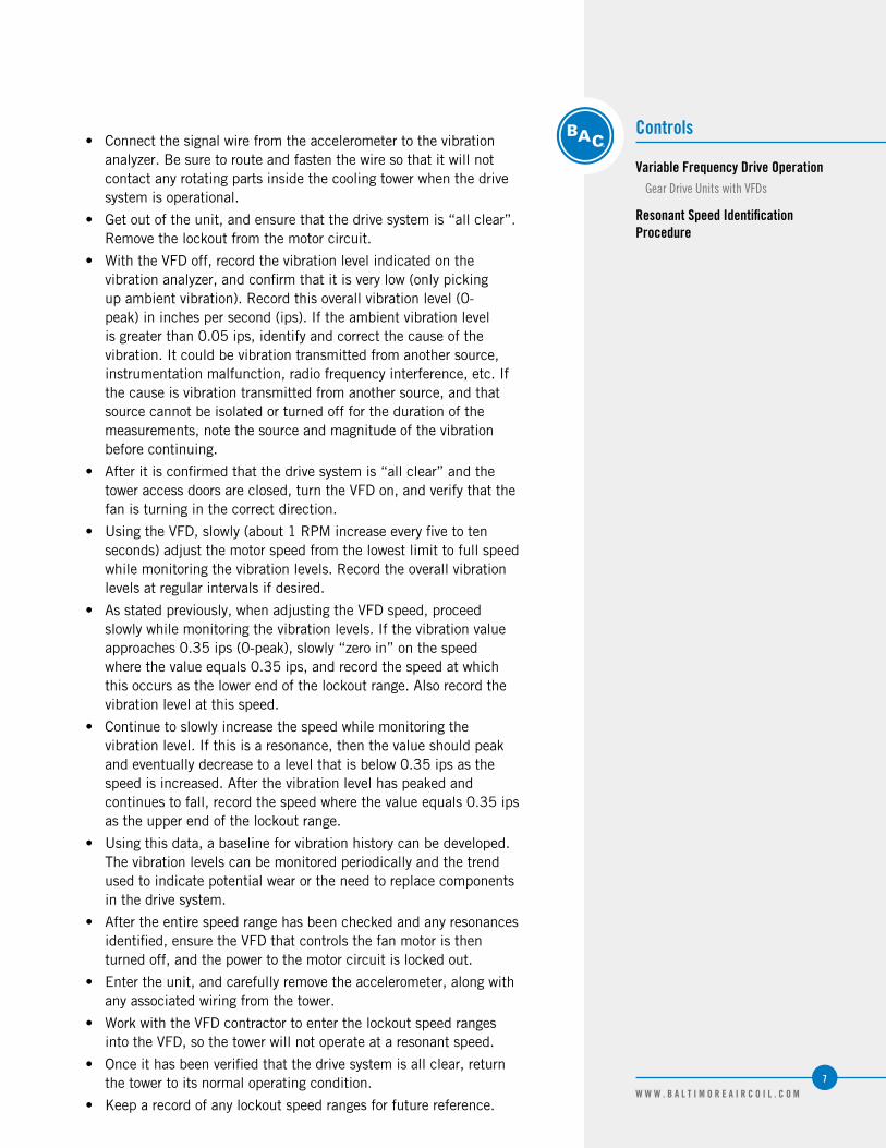
• Connect the signal wire from the accelerometer to the vibration analyzer. Be sure to route and fasten the wire so that it will not contact any rotating parts inside the cooling tower when the drive system is operational.
• Get out of the unit, and ensure that the drive system is “all clear”. Remove the lockout from the motor circuit.
• With the VFD off, record the vibration level indicated on the vibration analyzer, and confirm that it is very low (only picking up ambient vibration). Record this overall vibration level (0-peak) in inches per second (ips). If the ambient vibration level is greater than 0.05 ips, identify and correct the cause of the vibration. It could be vibration transmitted from another source, instrumentation malfunction, radio frequency interference, etc. If the cause is vibration transmitted from another source, and that source cannot be isolated or turned off for the duration of the measurements, note the source and magnitude of the vibration before continuing.
• After it is confirmed that the drive system is “all clear” and the tower access doors are closed, turn the VFD on, and verify that the fan is turning in the correct direction.
• Using the VFD, slowly (about 1 RPM increase every five to ten seconds) adjust the motor speed from the lowest limit to full speed while monitoring the vibration levels. Record the overall vibration levels at regular intervals if desired.
• As stated previously, when adjusting the VFD speed, proceed slowly while monitoring the vibration levels. If the vibration value approaches 0.35 ips (0-peak), slowly “zero in” on the speed where the value equals 0.35 ips, and record the speed at which this occurs as the lower end of the lockout range. Also record the vibration level at this speed.
• Continue to slowly increase the speed while monitoring the vibration level. If this is a resonance, then the value should peak and eventually decrease to a level that is below 0.35 ips as the speed is increased. After the vibration level has peaked and continues to fall, record the speed where the value equals 0.35 ips as the upper end of the lockout range.
• Using this data, a baseline for vibration history can be developed. The vibration levels can be monitored periodically and the trend used to indicate potential wear or the need to replace components in the drive system.
• After the entire speed range has been checked and any resonances identified, ensure the VFD that controls the fan motor is then turned off, and the power to the motor circuit is locked out.
• Enter the unit, and carefully remove the accelerometer, along with any associated wiring from the tower.
• Work with the VFD contractor to enter the lockout speed ranges into the VFD, so the tower will not operate at a resonant speed.
• Once it has been verified that the drive system is all clear, return the tower to its normal operating condition.
• Keep a record of any lockout speed ranges for future reference.

COMMON
Cold Weather OperationInSPECTIOn AnD MAInTEnAnCE
FAn SECTIOn ICInG PROTECTIOn
COIL FREEzE PROTECTIOn
BASIn WATER AnD InTERnAL PIPInG FREEzE PROTECTIOn
2

9W W W . B A L T I M O R E A I R C O I L . C O M
Inspection and Maintenance
BAC products can be operated at subfreezing ambient temperatures provided proper operating methods are established and diligently followed.
• Carry out frequent visual inspections and routine maintenance services during operation in subfreezing weather.
• Ensure all controls for capacity and freeze protection are set properly and functioning normally.
• Prevent excessively high water levels and possible overflow of the cold water basin due to over pumping, clogged strainers, or make-up valve malfunction.
• Some unit icing can be expected in very cold weather. Usually this will not effect the operation of the unit. Resolve any icing conditions that may damage the unit or the supports, impair the system performance or create a safety hazard.
Fan Section Icing Protection
There are three basic operational methods which can be used to provide the system’s required cooling: temperature setting, fan control, and dry operation. The method of control employed on a given application depends upon the climatic extremes which are expected, the variations in heat load that will be encountered, and the compatibility of the control system with other portions of the installation. Effective icing control in subfreezing ambient conditions may require a combination of these three methods.
Temperature SettingLow leaving fluid temperatures promote ice formation. During operation in subfreezing ambient temperatures, maintain the leaving fluid temperature as high as possible. Ensure the unit operates with the maximum possible heat load. The recommended minimum process fluid temperature is:
• 43°F (6.1°C) for crossflow cooling towers
• 42°F (5.5°C) for counterflow cooling towers
• 50°F (10°C) for closed circuit cooling towers with water (non-glycol) as the heat transfer liquid
• 45°F (7.2°C) for closed circuit cooling towers with glycol as the heat transfer liquid
NOTE: Dry operation applies only
to closed circuit cooling towers
and evaporative condensers.
Cold Weather Operation
Inspection and Maintenance
Fan Section Icing ProtectionTemperature Setting
10W W W . B A L T I M O R E A I R C O I L . C O M
Fan ControlReduce the unit capacity by cycling fans, thus modulating the airflow through the unit. Rapid on-off cycles can cause the fan motor to overheat. Set the controls to allow a maximum of six on-off cycles per hour. Periodically, cycle the fans off to prevent ice formation and/or to melt ice that accumulates on the intake louvers or combined inlet shields and face of the fill. The following are fan control methods:
• Variable Frequency Drives: VFDs offer the most precise method of capacity control by modulating fan motor speed. When using VFDs, avoid operating at or near resonant speeds. Units with VFDs require premium efficient/inverter duty motors.
• Fan Cycling: Operate each unit with the highest thermal load it can handle, rather than evenly dividing the total heat load across all cells. During prolong cold weather periods, bypass the idle units and drain the basins.
• Multi-Speed Motors: If the unit is equipped with 2-speed motors or BALTIGUARD™/BALTIGUARD PLUS™ Fan System, operation at a lower speed may be sufficient to prevent icing. The motor starter should include a minimum 15 second time delay when switching from high to low speed.
In subfreezing ambient temperatures, cycle the fan off for five minutes every 15 to 20 minutes for each cell. If ice continues to build on the louvers, decrease the on-time. Observe the inlet louvers of the towers at least every four to eight hours.
Fan Reversal This procedure should be used only after the other methods of fan control fail. If utilized, the fans should be run in reverse for no longer than 20 minutes and the cooling tower should be observed during this time. Before returning to normal operation, visually inspect the fan blades for ice formation.
Dry Operation for Models FXV, CXVB, PC2, VF1, VFL, VCA, VC1, VCL, and HXVOne method to prevent icing is dry operation. Dry operation of the closed circuit cooling tower or evaporative condenser protects fans from ice formation due to mist and splash from the cold water basin.
NOTE: Modulating the water
flow rate to the unit is nOT
a recommended method of
controlling cooling capacity.
11W W W . B A L T I M O R E A I R C O I L . C O M
Cold Weather Operation
Fan Section Icing ProtectionFan Control
Fan Reversal
Dry Operation for Models FXV, CXVB, PC2, VF1, VFL, VCA, VC1, VCL, and HXV
Coil Freeze ProtectionMinimum Operation
Coil Freeze Protection
For protection against coil freeze-up, recommended solutions are an industrial grade inhibited ethylene glycol or propylene glycol solution. When the use of glycol is not practical, the system must be designed to meet both minimum flow and minimum temperature requirements.
Coil volumes for models FXV, HXV, VF1, and VFL can be found in the corresponding Engineering Data section at www.BaltimoreAircoil.com. Coil volume for CXVB, PC2, VCA, VC1, and VCL condenser models using liquid cooling circuits is job specific.
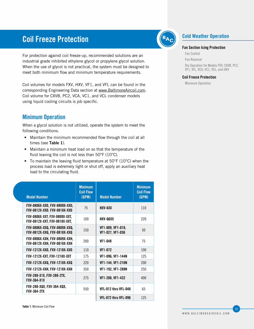
Minimum OperationWhen a glycol solution is not utilized, operate the system to meet the following conditions.
• Maintain the minimum recommended flow through the coil at all times (see Table 1).
• Maintain a minimum heat load on so that the temperature of the fluid leaving the coil is not less than 50°F (10°C).
• To maintain the leaving fluid temperature at 50°F (10°C) when the process load is extremely light or shut off, apply an auxiliary heat load to the circulating fluid.
Model Number
Minimum Coil Flow
(GPM) Model Number
Minimum Coil Flow
(GPM)
FXV-0806X-XXD, FXV-0809X-XXD, FXV-0812X-XXD. FXV-0818X-XXD 75 HXV-6XX 110
FXV-0806X-XXT, FXV-0809X-XXT, FXV-0812X-XXT, FXV-0818X-XXT, 100 HXV-Q6XX 220
FXV-0806X-XXQ, FXV-0809X-XXQ, FXV-0812X-XXQ, FXV-0818X-XXQ 150
VF1-009, VF1-018, VF1-027, VF1-036 50
FXV-0806X-XXH, FXV-0809X-XXH, FXV-0812X-XXH, FXV-0818X-XXH 200 VF1-048 75
FXV-1212X-XXD, FXV-1218X-XXD 110 VF1-072 100
FXV-1212X-XXT, FXV-1218X-XXT 175 VF1-096, VF1-144N 125
FXV-1212X-XXQ, FXV-1218X-XXQ 220 VF1-144, VF1-216N 200
FXV-1212X-XXH, FXV-1218X-XXH 350 VF1-192, VF1-288N 250
FXV-288-X1X, FXV-288-2TX, FXV-364-X1X 275 VF1-288, VF1-432 400
FXV-288-XQX, FXV-364-XQX, FXV-364-2TX 550 VFL-012 thru VFL-048 65
VFL-072 thru VFL-096 125
Table 1. Minimum Coil Flow

12W W W . B A L T I M O R E A I R C O I L . C O M
NOTES:
1. One inch thick PVC nitrite
rubber blend thermal
insulation on both the PCD
hood and the casing panels
surround the coil.
2. Heat loss is based on 50°F
(10°C) coil water and -10°F
(-23.3°C) ambient air with a
45 MPH wind. The fan(s) and
pump(s) are turned off.
Model Number Standard UnitUnit with PCD
HoodUnit with PCD Hood
& Insulation[1]
FXV-0806X-12DFXV-0806X-16DFXV-0806x-20DFXV-0806X-24DFXV-0806X-28DFXV-0806x-32DFXV-0806x-36DFXV-0806X-24TFXV-0806x-30TFXV-0806x-36TFXV-0806x-16QFXV-0806x-24QFXV-0806x-32Q
82,00097,100
111,400140,200153,000165,100176,700141,200160,500178,40098,100
142,200168,000
46,20045,90045,60061,30060,90060,60060,20061,90061,50061,10046,60062,60062,200
34,70034,50034,20044,60044,40044,10043,90045,10044,80044,50035,00045,60045,300
FXV-0809X-12DFXV-0809x-16DFXV-0809x-20DFXV-0809x-24DFXV-0809x-28DFXV-0809X-32DFXV-0809X-36DFXV-0809x-24TFXV-0809X-30TFXV-0809X-36TFXV-0809x-16QFXV-0809x-24QFXV-0809X-32Q
118,700141,500163,000203,100222,000239,900256,800205,300233,900260,400143,600207,500246,200
60,40059,80059,20079,30078,60077,90077,30080,70079,80079,10061,20082,00081,300
47,40046,90046,40060,20059,60059,10058,60061,20060,50060,00048,00062,20061,600
FXV-0812x-12DFXV-0812x-16DFXV-0812x-20DFXV-0812x-24DFXV-0812X-28DFXV-0812X-32DFXV-0812X-36DFXV-0812X-24TFXV-0812X-30TFXV-0812X-36TFXV-0812x-16QFXV-0812X-24QFXV-0812X-32Q
154,900185,000213,400264,100288,800312,200334,000267,900305,600340,300188,700271,700323,100
74,30073,20072,20096,50095,30094,20093,20098,70097,40096,10075,500
101,00099,700
59,80058,90058,10075,00074,10073,20072,40076,70075,60074,60060,80078,40077,500
FXV-0818X-12DFXV-0818X-16DFXV-0818X-20DFXV-0818X-24DFXV-0818X-28DFXV-0818X-32DFXV-0818X-36DFXV-0818X-24TFXV-0818X-30TFXV-0818X-36TFXV-0818X-16QFXV-0818X-24QFXV-0818X-32QFXV-0818X-36H
225,500269,600310,600381,100416,200449,100479,800389,200443,600493,200277,700397,500472,700514,300
100,90098,70096,700
128,500126,100123,800121,700132,900130,200127,600103,500137,500135,000137,100
83,60081,80080,100
102,500100,60098,80097,100
106,000103,800101,80085,700
109,700107,700109,300
Table 2. FXV-0806X thru FXV-0818X Heat Loss Data (BTU/hour)[2]
Positive Closure Damper Hood and InsulationThe amount of auxiliary heat required can be substantially reduced by the use of a positive closure damper hood and insulation on the hood and casing. The heat loss data can be found in Tables 2, 3, 4, and 5.

13W W W . B A L T I M O R E A I R C O I L . C O M
Cold Weather Operation
Coil Freeze ProtectionPositive Closure Damper Hood and Insulation
NOTES:
1. One inch thick PVC nitrite
rubber blend thermal
insulation on both the PCD
hood and the casing panels
surround the coil.
2. Heat loss is based on 50°F
(10°C) coil water and -10°F
(-23.3°C) ambient air with a
45 MPH wind. The fan(s) and
pump(s) are turned off.
Model Number Standard UnitUnit with PCD
HoodUnit with PCD Hood
& Insulation[1]
FXV-1212X-12DFXV-1212X-16DFXV-1212X-20DFXV-1212X-24DFXV-1212X-28DFXV-1212X-32DFXV-1212X-36DFXV-1212X-24TFXV-1212X-30TFXV-1212X-36TFXV-1212X-16QFXV-1212X-24QFXV-1212X-32QFXV-1212X-36H
228,300277,800324,000394,300434,600472,400507,900403,100465,700523,100283,600406,200489,900536,300
83,10081,70080,500
107,500106,000104,600103,300111,600110,100108,80084,600
113,000111,500113,700
70,70069,50068,50086,50085,30084,20083,10089,80088,60087,60072,00091,00089,70091,500
FXV-1218X-12DFXV-1218X-16DFXV-1218X-20DFXV-1218X-24DFXV-1218X-28DFXV-1218X-32DFXV-1218X-36DFXV-1218X-24TFXV-1218X-30TFXV-1218X-36TFXV-1218X-16QFXV-1218X-24QFXV-1218X-32QFXV-1218X-36H
331,900404,200471,100567,700625,000678,200728,000586,700677,600760,500416,900593,400716,100789,300
109,000106,400103,900137,800134,900132,300129,800145,800143,000140,400112,200148,700145,700150,100
97,00094,60092,500
115,600113,200110,900108,800122,300119,900117,70099,800
124,700122,200125,900
FXV-288-31XFXV-288-41XFXV-288-2TXFXV-288-1QX
760,200881,100881,100881,100
280,700294,500294,500294,500
202,000211,000211,000211,000
FXV-364-31XFXV-364-41XFXV-364-2TXFXV-364-1QX
894,0001,036,2001,036,2001,036,200
330,100346,400346,400346,400
237,600248,100248,100248,100
Model Number Standard UnitUnit with PCD
HoodUnit with PCD Hood
& Insulation[1]
VFL-012-02VFL-012-12VFL-012-22VFL-012-32
19,20025,00029,90033,800
16,50017,80019,20020,500
11,00011,90012,80013,700
VFL-024-12VFL-024-22VFL-024-32
48,20057,70065,400
28,50030,40032,300
19,00020,30021,500
VFL-036-22VFL-036-33
87,00098,400
47,10049,800
30,70032,500
VFL-048-22VFL-048-31VFL-048-41
126,400138,800151,200
66,00069,30072,600
42,60044,80047,000
VFL-072-22VFL-072-31VFL-072-41
210,900234,100252,900
84,40087,90091,400
56,20058,60060,900
VFL-096-41 311,700 103,600 69,000
Table 3. FXV-1212X thru FXV-1218X and FXV-288 thru FXV-364 Heat Loss Data (BTU/hour)[2]
Table 4. VFL Heat Loss Data (BTU/hour)[2]

14W W W . B A L T I M O R E A I R C O I L . C O M
NOTES:
1. One inch thick PVC nitrite
rubber blend thermal
insulation on both the PCD
hood and the casing panels
surround the coil.
2. Heat loss is based on 50°F
(10°C) coil water and -10°F
(-23.3°C) ambient air with a
45 MPH wind. The fan(s) and
pump(s) are turned off.
Model Number Standard UnitUnit with PCD
HoodUnit with PCD Hood
& Insulation[1]
VF1-009-12VF1-009-22VF1-009-32VF1-009-42
24,30029,40032,90034,800
17,10018,80020,50022,200
10,30012,00012,00013,700
VF1-018-02VF1-018-12VF1-018-22VF1-018-32VF1-018-42
34,70046,20056,00064,30070,950
25,60027,30029,10030,80032,550
15,40015,40017,10017,10018,800
VF1-027-22VF1-027-32VF1-027-42
86,10097,700
106,300
46,10049,50052,900
27,30029,10029,100
VF1-036-21VF1-036-31VF1-036-41VF1-036-51
112,600128,900145,000161,500
63,20066,60070,00073,400
39,30039,30043,60043,600
VF1-048-21VF1-048-31VF1-048-41
154,900177,200197,000
80,20083,70085,600
52,90052,90054,600
VF1-072-21VF1-072-31VF1-072-41
212,400241,100269,800
83,70087,10090,500
51,20051,20056,800
VF1-096-31VF1-096-41VF1-096-51
286,700312,100329,800
97,600102,600107,900
60,00060,90061,700
VF1-144N-21VF1-144N-31VF1-144N-41
381,400429,900464,800
128,300134,700141,400
81,30082,80084,400
VF1-144-21VF1-144-31VF1-144-41
385,000435,500474,600
139,900146,900154,200
88,60090,20091,900
VF1-192-31VF1-192-41VF1-192-51
576,300627,300662,800
228,400240,100252,500
153,600156,700160,100
VF1-216-21VF1-216-31VF1-216-41
579,900653,500707,300
194,000203,700213,800
122,900125,100127,300
VF1-288N-21VF1-288N-31VF1-288N-41
762,800859,800929,600
256,600269,400282,800
162,600165,600168,800
VF1-288-21VF1-288-31VF1-288-41
750,800849,300925,600
260,300273,300286,800
171,900175,000178,300
VF1-432-21VF1-432-31VF1-432-41
1,142,5001,287,4001,393,500
390,000409,500429,800
259,400264,000268,500
Table 5. VF1 Heat Loss Data (BTU/hour)[2]
15W W W . B A L T I M O R E A I R C O I L . C O M
Cold Weather Operation
Coil Freeze ProtectionPositive Closure Damper Hood and Insulation
Emergency Coil Drain
Basin Water and Internal Piping Freeze Protection
Cold Water Basin Protection
NOTE: For remote sump
applications, the water level in
the basin of the equipment is a
function of the design flow rate,
the quantity, size and location
of the remote sump connection
and the pipe design between the
cooling tower and remote sump.
Units installed on remote sump
applications are supplied without
a make-up connection.
Emergency Coil DrainDo not drain the coil as a normal method of freeze protection. Frequent draining promotes corrosion inside the coil tube. However, draining is acceptable as an emergency method of freeze protection if the coil is not protected by a glycol solution. If the coil is not protected, an automatic drain valve and vacuum breaker are recommended to drain the coil if flow stops or the fluid temperature drops below 50°F (10°C) when the ambient temperature is below freezing. Further protection against coil freeze-up is possible with the installation of an alarm to alert personnel when the temperature of the fluid leaving the coil falls below 50ºF (10°C). Contact your local BAC Representative for guidelines on the installation of an emergency coil drain system.
Basin Water and Internal Piping Freeze Protection
Cold Water Basin ProtectionThe basin water could freeze when the unit is shut-down and exposed to subfreezing ambient temperatures.
• Remote Sump: The ideal method of protection is a remote sump located in a heated indoor area. When the circulating pump stops, the water in the connecting piping will drain by gravity to this indoor sump.
• Basin Heaters: On applications without a remote sump, heat must be provided to the cold water basin. Electrical immersion heaters, steam coils or hot water coils can provide the required function. Contact your local BAC Representative for details.
• Electric Water Level Control: An electric water level control will maintain the proper water level regardless of the thermal load or variations in make-up water supply pressure. The two-position, slow closing solenoid valve provided with the BAC electric water level control package also minimizes valve freezing problems.
• Heat Tracing: Heat trace and insulate all exposed water piping including pump piping below the overflow level, external header cleanout (PT2 only) and make-up water lines with electrical heater tape.

16W W W . B A L T I M O R E A I R C O I L . C O M
EASY CONNECT® Piping Arrangement Freeze Protection• Eliminate all water in the optional EASY CONNECT® Piping
Arrangement (Series 3000) and in all internal piping when the tower is idle.
• It is essential to drain water from the EASY CONNECT® Piping Arrangement and internal piping whenever the potential for freezing temperatures exists. Drain the water by using 1/2” NPT drain port located on the inboard side of the EASY CONNECT® Piping Arrangement.
• There are three recommended methods for draining the piping:
– Preferred: Install a normally open 1/2” solenoid valve on the 1/2” drain connection of the EASY CONNECT® Piping Arrangement. Wire the valve in the pump circuit so the valve closes when the pump is energized. Select the solenoid valve to operate with a minimum pressure differential of 0 psi, which is required to limit the static head imposed on the valve from the water column.
– Install a 1/2” manual valve on the 1/2” drain connection of the EASY CONNECT® Piping Arrangement. Open the valve during the cold weather operation. Keep the valve closed during the warm weather to achieve full thermal performance.
– Remove the 1/2” plug from the 1/2” drain connection of EASY CONNECT® Piping Arrangement during the cold weather operation. Reinstall the plug during the warm weather to obtain full thermal performance.
Figure 2. EASy COnnECT® Piping Arrangement

COMMON
Corrosion ProtectionWATER TREATMEnT
CORROSIOn AnD SCALE COnTROL
CHEMICAL TREATMEnT REqUIREMEnTS
PASSIVATIOn
LOnG TERM CARE OF STAInLESS STEEL
BIOLOGICAL COnTROL
SySTEM CLEAnInG
3
18W W W . B A L T I M O R E A I R C O I L . C O M
NOTE: Since the quality of the
ambient air and make-up water
varies significantly from job
site to job site, BAC strongly
recommends obtaining the
services of a competent water
treatment specialist prior to the
initial start-up of the evaporative
cooling equipment. Additionally,
to protect against the risk of
Legionella contamination, never
operate the cooling equipment
without adequate biological
control.
BAC products are constructed of corrosion-resistant materials. The fill is made of a polyvinyl chloride (PVC), which requires no protection against rot, decay, rust or biological attack. Other materials listed below are used in the equipment construction:
• Galvanized Steel Components: Inspect the galvanized steel components for blemishes or corrosion. Wire brush and recoat the affected areas with a cold galvanizing compound such as zinc rich compound (ZRC).
• Thermosetting Hybrid Polymer Components: Galvanized steel components protected with the thermosetting hybrid polymer can be scratched, scraped or blemished. To touch up these use a repair kit (BAC Part # 16-133P) available from your local BAC Representative.
• Stainless Steel Components: Inspect stainless steel components for signs of blemishes or corrosion. See “Long Term Care of Stainless Steel” on Page 21 for cleaning and care instructions.
• Fiberglass Reinforced Polyester (FRP) Components: Series 3000, dual air inlet FXV, and CXV-T products are provided with FRP casing panels as standard. Inspect the casing panels for accumulation of dirt and clean them with soap and water as necessary.
• TriArmor® Corrosion Protection System: Inspect components protected with the TriArmor® Corrosion Protection System for signs of deep scratches or blemishes, especially in areas with field penetrations. Touch these up with 3M™ Windo-Weld™ Super Fast Urethane which is available through your local BAC Representative (BAC Part # RK1015).
• Pultruded Fiberglass Reinforced Polyester (PFRP) Components: Series 3000 Cooling Towers are optionally provided with PFRP hot water basins. Inspect the basin panels for accumulation of dirt and clean them with soap and water as necessary.
Water Treatment
A proper water treatment program, administered under the supervision of a competent water treatment specialist, is an essential part of routine maintenance to ensure the safe operation and longevity of evaporative cooling equipment, as well as other system components.
In evaporative cooling products, cooling is accomplished by evaporating a small portion of the recirculating water as it flows through the unit. As the water evaporates, the dissolved solids originally present in the water remain behind and if not controlled, the concentration of dissolved solids will increase rapidly. This can lead to corrosion, scale or biological fouling which may negatively affect heat transfer as well as the longevity of system components.

19W W W . B A L T I M O R E A I R C O I L . C O M
Corrosion Protection
Water Treatment
Corrosion and Scale Control
• Corrosion – Red rust on steel components and white rust on galvanized surfaces may affect the longevity of system components.
• Scale Formation – Scale not only reduces heat transfer and system efficiency, but also may lead to under deposit corrosion. If scale is not controlled, it may continue building on critical components such as the fill and severely impact thermal performance.
• Biological Fouling – Slime and algae formations may reduce heat transfer, promote corrosion, and harbor pathogens such as Legionella.
Corrosion and Scale Control
• To control corrosion and scale, maintain the water chemistry of the recirculating water within the parameters listed in Table 6. The specific measures required vary from system to system and are dependent on the chemistry of the make-up water, the metallurgy of the piping and heat transfer devices exposed to the recirculating water, and the temperatures at which the system will be operating.
• Bleed/blowdown, the continuous flow of a small portion of the recirculating water to a drain, is used to control the concentration of dissolved solids. On rare occasions, this may be adequate to control scale and corrosion. More often, chemical scale and corrosion inhibitors are necessary, which raise the allowable level of dissolved solids without the risk of scale and corrosion.
• Keep the chemically treated water within the guidelines given in Table 6. In cases where bleed/blowdown alone is being employed for corrosion and scale control without chemical treatment your water treatment specialist may recommend more conservative limits than those shown in Table 6.
Property of Water Recommended Level
pH 6.5 to 9.0[1]
Hardness as CaCO3 30 to 750 ppm[2]
Alkalinity as CaCO3 500 ppm maximum[2]
Total Dissolved Solids (TDS) 1500 ppm maximum
Conductivity 2400 micromhos[3]
Chlorides250 ppm maximum Cl
(410 ppm maximum as naCl)
Sulfates 250 ppm maximum
Silica 150 ppm maximum
Table 6. quality Guidelines for Chemically Treated Circulating Water
NOTES:
1. Galvanized steel units require
passivation in order to
prevent white rust (refer to
“Passivation” on Page 20).
2. Hardness and alkalinity limits
may be exceeded under certain
circumstances. Consult your
water treatment specialist for
recommendations.
3. The conversion factor used to
determine conductivity is 0.625
(TDS = 0.625 x Conductivity).

20W W W . B A L T I M O R E A I R C O I L . C O M
Chemical Treatment Requirements
Chemical treatment programs must meet the following requirements:
• The chemicals must be compatible with the unit materials of construction as well as other materials used in the system (pipe, heat exchanger, etc.).
• Chemical scale and corrosion inhibitors, particularly acid (if used), should be introduced into the circulating water through automatic feeders. This should be done at a point in the system where total mixing and dilution occur before reaching the evaporative cooling equipment. The preferred injection point for chemical scale and corrosion inhibitors is on the discharge side of the system circulating pump(s). These chemicals should not be batch fed directly into the unit’s cold water basin or water distribution system, as this can severely damage areas directly contacted.
• When chlorine is added to the system, free residual chlorine should not exceed 1 ppm, except as noted in start-up and shutdown section. Exceeding this limit may accelerate corrosion.
Passivation
• Passivation is the formation of a protective, passive, carbonate layer on galvanized steel surfaces.
• To provide maximum protection from corrosion on newly installed units take special measures to passivate galvanized steel surfaces.
• To ensure proper passivation of the galvanized steel, keep the pH of the circulating water between 7.0 to 8.2 for four to eight weeks after start-up, or until new zinc surfaces turn dull gray in color.
• If white rust forms on galvanized steel surfaces after the pH is returned to normal service levels, it may be necessary to repeat the passivation process.
NOTE: Stainless steel cold water
basins and basins protected by
the TriArmor® Corrosion Protection
System or thermosetting
hybrid polymer do not require
passivation. However, if the upper
structure is galvanized steel,
passivation is required.

21W W W . B A L T I M O R E A I R C O I L . C O M
Corrosion Protection
Chemical Treatment Requirements
Passivation
Long Term Care of Stainless SteelBAC’s Manufacturing Process
Recommended Cleaning Procedure
Long Term Care of Stainless Steel
When the percentage of chromium in steel exceeds 10.5%, it is called stainless steel. The chromium in the steel reacts with the oxygen in the air to form a chromium-oxide surface layer, also called the passivation layer. Galvanized steel also has a passivation layer, but it is of less rugged zinc-oxide. It is stainless steel’s chromium-oxide passivation layer that provides the corrosion resistance in stainless steel.
BAC’s Manufacturing ProcessBAC takes precautions to prevent cross-contamination, processing galvanized and stainless steel parts separately. Also, stainless steel brushes are used to clean welds on stainless parts and care is taken to avoid scratching parts during processing. Organic cleaners are used to clean the finished product prior to shipping.
Jobsite ConsiderationsWhile stainless steel itself does not rust so long as the chromium-oxide surface layer is intact, it is not immune to contamination from its surroundings. Some common sources of surface contamination are:
• Dirt and soil
• Shop oil or grease that may carry other contaminants such as metal chips
• Machining or welding galvanized steel at the jobsite may cause debris to impinge itself into the stainless steel
These contaminants can deposit on the surface and scratch the passivation layer or prevent it from re-forming. They can also get trapped underneath the passivation layer and reduce corrosion resistance.
Recommended Cleaning ProcedureStainless steel needs to be cleaned regularly to maintain the corrosion resistance as well as to maintain the overall aesthetics of the stainless steel.
It is fairly simple to clean most contaminants off the surface of stainless steel. Most dirt and soil can be cleaned with a clean cloth, warm water, and mild detergent. For persistent dirt, a little vinegar can be added in the cleaning water. It is important to always rinse the surface with warm water and wipe with a dry cloth after any cleaning, whether mild or aggressive.

22W W W . B A L T I M O R E A I R C O I L . C O M
• Fingerprints, mild stains or grease spots can be cleaned using organic solvents such as acetone, methyl or ethyl alcohol or mineral spirits. Stainless steel wipes or glass cleaners commonly available in stores may also be used.
• Occasionally the surface of stainless steel can get iron chips or shavings embedded in it from having galvanized steel machined or welded in the vicinity. The iron chips can start to rust, reducing the corrosion resistance of the stainless steel, and stain the surface giving the impression that the stainless steel is rusting. These types of contaminants require more aggressive cleaning. Mild abrasives such as Scotch-Brite™ products may be used where aesthetic considerations are not important followed by solvent cleaning with organic solvents as described above. It is important to rinse the surface with warm water and wipe with a dry cloth after cleaning.
• If the iron chips are not removed with the Scotch-Brite™ Products, electro-chemical cleaning may be required. BAC uses commercially available equipment for electro-chemical cleaning in the field. Contact your local BAC Representative for more information or to arrange a service call.
Biological Control
• The warm, oxygen and nutrient rich environment inside evaporative cooling equipment provides an ideal environment conducive to the growth of algae, slime, and other micro-organisms. Uncontrolled, this can reduce heat transfer, promote corrosion, and promote the growth of potentially harmful organisms such as Legionella. To avoid biological contamination and minimize the risk of Legionella, initiate the biocide treatment program at start-up and continue on a regular basis thereafter in accordance with the treatment supplier’s instructions.
• Bleed/blowdown or chemical treatment used for corrosion and scale control alone is not adequate for control of biological contamination.
• Introduce solid or granular biocides through a chemical “pot” feeder installed in parallel with the system circulating pump. Diluted liquid biocides may be added directly to the cold water basin.
• If ozone water treatment is used, at no point should concentrations exceed 0.5 ppm.
CAUTION: never use chloride or
chlorine based solvents such as
bleach or muriatic (hydrochloric)
acid to clean stainless steel. It
is important to rinse the surface
with warm water and wipe with a
dry cloth after cleaning.
NOTE: Long term care of stainless
steel information reprinted with
permission from “The Care and
Cleaning of Stainless Steel”;
Specialty Steel Industry of north
America; http://www.ssina.com.

23W W W . B A L T I M O R E A I R C O I L . C O M
Corrosion Protection
Long Term Care of Stainless SteelRecommended Cleaning Procedure
Biological Control
Initial Start-up and Start-up Following a Shutdown Period:
• To minimize the risk of biological contamination during a shut-down period of three days or more, it is recommended that the entire system (evaporative cooling equipment, system piping, heat exchangers, etc.) be drained.
• To resume operation of a drained system and at initial start-up, clean all debris from the cold water basin and fill the system with fresh water. Then execute one of the following biocide treatment programs while operating the circulating pump and prior to operating the unit fans:
– Resume treatment with the biocide that was used prior to shut-down. Operate the pump only while maintaining the maximum recommended biocide residual for a sufficient duration (residual and time will vary with the biocide) as recommended by the water treatment supplier. Start the fan only after this treatment period is completed.
– Check the pH of the circulating water and, if necessary, adjust it to 7.0 - 7.6 pH. Then, running the pump only, treat the system with sodium hypochlorite to maintain a level of 4 to 5 mg/l (ppm) free chlorine (as Cl2) over a six hour period. Test kits for measuring the free residual of chlorine are commercially available. Start the fan only after this treatment period is completed.
• When it is not practical to drain the system during shut-down periods, install a by-pass line with shut-off valves to permit the recirculating water to circulate throughout the system, including the unit basin, while bypassing the fill section of the evaporative cooling equipment (fans should remain off).
• Treat the system as per one of the above-described methods prior to restarting the unit.
24W W W . B A L T I M O R E A I R C O I L . C O M
System Cleaning
System Cleaning for Models FXV, VF1, VFL, and HXVWith proper precautions, prior to start-up circulate an alkaline solution which can be used to clean condenser water systems through a closed circuit cooling tower. The necessary precautions include:
• Limit the duration of the cleaning to one day or at the most two days.
• The temperature of the solution should never exceed 100ºF (37.8°C).
• The maximum concentration of chemicals in the circulation solution should not exceed any of the following:
– 5% Sodium Hydroxide
– 5% Sodium Metasilicate
– 2% Sodium Carbonate
– 2% Tetra Sodium Pyrophosphate
– 0.5% Trisodium Phosphate
– 0.5% Sodium Nitrate
– 5-10% Butyl Cellosolve
Coil Cleaning for Models FXV, VF1, VFL, and HXVThe outside of the heat exchange coil may require occasional cleaning. The chemicals used must be compatible with the materials being treated. For example, the standard coil outside is galvanized steel. The inside of the coil is black carbon steel. For finned coils, the coil cleaning must be careful not to damage the fins (outside of the coils) and the coils themselves. For specific recommendations on coil cleaning, contact a qualified consultant.
Weld Byproduct Cleaning for Models CXVB, CXV-T, PC2, VCA, VCL and VC1The installation and manufacturing processes commonly used for field assembly of steel-piped systems may leave weld byproducts inside coils and connecting piping (especially in refrigeration systems). It is common practice to install filters and/or strainers that remove contaminants during initial system operation. Shortly after system startup, the filters and/or strainers should be cleaned or replaced.

COMMON
Bleed RateBLEED RATE 4

26W W W . B A L T I M O R E A I R C O I L . C O M
Bleed Rate
• In evaporative cooling, evaporation of a small portion of the recirculating spray water as it flows through the equipment causes the cooling effect. As this water evaporates, the impurities originally present remain in the recirculating water. The concentration of the dissolved solids increases over time and can reach unacceptable levels.
• In addition, airborne impurities are often introduced into the recirculating water. If these impurities and contaminants are not effectively controlled, they can cause scaling, corrosion, and sludge accumulations that reduce heat transfer efficiency and increase system-operating costs, potentially shortening the useful life of the equipment.
• The degree to which dissolved solids and other impurities build up in the recirculating water may be defined as the cycles of concentration. Specifically, cycles of concentration equals the ratio of the concentration of dissolved solids (for example - chlorides, sulfates, etc.) in the recirculating water to the concentration of the same material in the make-up water.
• In order to optimize heat transfer efficiency and maximize equipment life, “bleed” or “blowdown” a small amount of recirculating water from the system. This controls the cycles of concentration to maintain the quality of the recirculating water within the guidelines given in Table 6, on Page 19.
• Replenish the “bleed” water with fresh make-up water, thereby limiting the build-up of impurities.
• Bleed/blowdown:
– Accomplish the bleed automatically through a solenoid valve controlled by a conductivity meter. The set point is the water conductivity at the desired cycles of concentration and should be determined by a competent water treatment expert.
– Alternatively, use a bleed line with a valve to continuously bleed from the system. In this arrangement, adjust the rate of bleed using the valve in the bleed line. Measure the rate of bleed by filling a container of known volume while noting the duration. Check the bleed rate and water quality periodically to ensure that adequate control of the water quality is being maintained.
NOTE: A proper water treatment
program, administered under
the supervision of a competent
water treatment specialist, is
an essential part of routine
maintenance to ensure the
safe operation and longevity of
evaporative cooling equipment,
as well as other system
components.
NOTE: The solenoid valve and
conductivity meter must be
supplied by others.

27W W W . B A L T I M O R E A I R C O I L . C O M
Bleed Rate
Bleed RateBleed Line Calculations: Bleed rate is determined by the following formula:
Bleed Rate = B = E
Where: B = Bleed Rate (GPM)
E = Evaporation Rate (GPM) = Q (GPM) x R (°F) x 0.001
Q = Process Fluid Flow Rate (GPM)
R = Range
n = Number of Cycles of Concentration = CR/CM
CR = Concentration in Recirculating Water
CM = Concentration in Make-up Water
The following example illustrates a bleed rate calculation:
Given:
• Closed Circuit Cooling Tower
• Process Fluid Flow Rate = 800 GPM
• Maximum Allowable Chloride Concentration = 250 ppm
• Concentration of Chlorides in Make-up Water = 45 ppm
• Range = 10°F
Find: Bleed Rate
Solution: So in this case,
E = Q * R * 0.001 = 800 * 10 * 0.001 = 8 GPM
n = CR = 250 ppm = 5.55
Bleed Rate = B = E = 8 GPM = 1.75 GPM
Therefore, in this case we must bleed approximately 1.75 GPM to limit the concentration of impurities.
This example focuses on a single parameter (chloride concentration) of water only. The bleed rate required for a system (when evaluating more than one parameter) is the highest bleed rate required to keep all parameters within recommended limits.
NOTE: The evaporation rate (E)
can be determined by any one of
the following methods:
• The evaporation rate is
approximately 2 GPM per 1
million BTUH of heat rejection.
• The evaporation rate is
approximately 3 GPM per 100
tons of refrigeration.
• Evaporation Rate =
q (GPM) * R * 0.001
as shown in the example.
(n-1)
CM 45 ppm
(n-1) (5.55-1)
NOTE: Evaporation is proportional
to the load and will vary
seasonally. BAC recommends the
use of a conductivity meter to
maximize water conservation.

COMMON
Basin Heater and Stand Alone Heater Control PanelBASIn HEATER
STAnD ALOnE BAC HEATER COnTROL PAnEL
5

29W W W . B A L T I M O R E A I R C O I L . C O M
Basin Heater
The cold water basin heater consists of one or more electric immersion heaters. It is designed to prevent the cold water basin from freezing during shutdown or standby. The heaters are sized for the specific application. The heating element has an enclosure that is suitable for outdoor use.
OperationEnsure that the heating element is completely submerged before energizing the main disconnect. For installations that have a BAC Controls Enclosure, please contact your local BAC Representative. For installations that use a stand alone BAC heater control panel, see below.
WARNING: The basin heater is not
designed to prevent icing during
unit operation.
Basin Heater and Stand Alone Heater Control Panel
Basin HeaterOperation
Stand Alone BAC Heater Control Panel
Figure 3. Basin Heater
Stand Alone BAC Heater Control Panel
The heater control system consists of a heater control panel and a combination temperature/liquid level sensor. The stainless steel 1/4” NPT sensor has an on/off relay output that de-energizes the heaters whenever the basin liquid temperature is above 45°F (7.2°C), or whenever the sensor probe is not fully submersed. The control panel enclosure is suitable for outdoor use.
The control system utilizes a 24V combination temperature/low liquid level control sensor, which is powered by a transformer in the control panel. When the sensor provides a 24V signal back to the control panel, the panel sends a 24V control voltage to the magnetic contactors. When energized, the magnetic contactors supply line voltage to the heaters.
WARNING: The heater control
panel temperature/low level
control can only be used with
the supplied combination
temperature/liquid level sensor
probe. Please contact your
local BAC Representative for
replacement parts.
NOTE: Basin heater information
reprinted with permission from
InDEECO, O&M #76-2000-83-5.
30W W W . B A L T I M O R E A I R C O I L . C O M
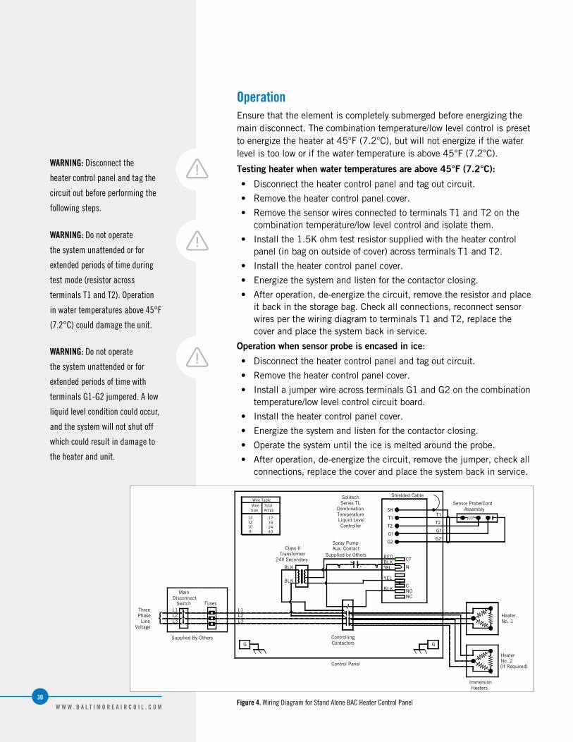
OperationEnsure that the element is completely submerged before energizing the main disconnect. The combination temperature/low level control is preset to energize the heater at 45°F (7.2°C), but will not energize if the water level is too low or if the water temperature is above 45°F (7.2°C).
Testing heater when water temperatures are above 45°F (7.2°C):
• Disconnect the heater control panel and tag out circuit.
• Remove the heater control panel cover.
• Remove the sensor wires connected to terminals T1 and T2 on the combination temperature/low level control and isolate them.
• Install the 1.5K ohm test resistor supplied with the heater control panel (in bag on outside of cover) across terminals T1 and T2.
• Install the heater control panel cover.
• Energize the system and listen for the contactor closing.
• After operation, de-energize the circuit, remove the resistor and place it back in the storage bag. Check all connections, reconnect sensor wires per the wiring diagram to terminals T1 and T2, replace the cover and place the system back in service.
Operation when sensor probe is encased in ice:
• Disconnect the heater control panel and tag out circuit.
• Remove the heater control panel cover.
• Install a jumper wire across terminals G1 and G2 on the combination temperature/low level control circuit board.
• Install the heater control panel cover.
• Energize the system and listen for the contactor closing.
• Operate the system until the ice is melted around the probe.
• After operation, de-energize the circuit, remove the jumper, check all connections, replace the cover and place the system back in service.
WARNING: Disconnect the
heater control panel and tag the
circuit out before performing the
following steps.
WARNING: Do not operate
the system unattended or for
extended periods of time during
test mode (resistor across
terminals T1 and T2). Operation
in water temperatures above 45°F
(7.2°C) could damage the unit.
WARNING: Do not operate
the system unattended or for
extended periods of time with
terminals G1-G2 jumpered. A low
liquid level condition could occur,
and the system will not shut off
which could result in damage to
the heater and unit.
MainDisconnect
Fuses
VoltageLine
PhaseThree
G G
Spray PumpAux. Contact
Supplied by Others
BLK
BLK
Class IITransformer
24V Secondary REDBLKYEL
YEL
BLK
ContactorsControlling
Control Panel
L1L2L3
ControllerLiquid LevelTemperatureCombination
Series TLSolitech
CT
N
CNONC
T1
T2
G1
G2
Shielded Cable
AssemblySensor Probe/Cord
G2
G1
T2
T1
SH
No. 1Heater{
40241612
8101214
Size AmpsWire TotalWire Table
L1L2L3
Switch
Supplied By Others
HeaterNo. 2(If Required)
ImmersionHeaters
Figure 4. Wiring Diagram for Stand Alone BAC Heater Control Panel

COMMON
Electronic Vibration Cutout SwitchELECTROnIC VIBRATIOn CUTOUT SWITCH
6
32W W W . B A L T I M O R E A I R C O I L . C O M
Electronic Vibration Cutout Switch
The BAC electronic switches utilize a solid state crystal accelerometer which provides an electrical output when it is deformed by the vibration forces. The output is electronically converted to a signal proportional to velocity. This signal is compared with a preset limit and triggers a solid state relay if the limit is exceeded.
An important feature of the vibration cutout switch is the built in time delay. This prevents triggering of the alarm or shutdown functions from transient increases in vibration levels. It also avoids shutdown due to transitory vibrations occurring during start-up. Three second alarm trip delay is standard, however time delays are independently adjustable in the field over a range of 2 to 15 seconds.
OperationTesting
“Test” position on the shutdown dial sets a minimum set point so that any vibration will cause trip condition. The light will come on immediately, and the trip will occur after duration of the time delay, providing that the complete system is operational. If test position is maintained for less than the duration of the time delay, trip will not occur, thus permitting system test without shutdown.
Remote Reset
Connection between terminals 5 and 6 latches triac output in the alarm state after setpoint is exceeded. Operating the connection will reset the output to non-alarm state.
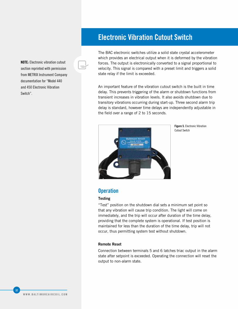
Figure 5. Electronic Vibration Cutout Switch
NOTE: Electronic vibration cutout
section reprinted with permission
from METRIX Instrument Company
documentation for “Model 440
and 450 Electronic Vibration
Switch”.

COMMON
Installation Instructions for Field ConnectionsInSTALLATIOn InSTRUCTIOnS
7

34W W W . B A L T I M O R E A I R C O I L . C O M
Installation Instructions
The following are installation instructions for adding new field connections (Equalizer/Bypass/Outlet) on a cold water basin with the TriArmor® Corrosion Protection System.
1. Use the BAC template provided with the accessory to layout and mark the hole pattern on the exterior of the cold water basin.
2. Drill a pilot hole from the outside of the cold water basin to the inside of the cold water basin.
3. On the inside of the cold water basin:
a. For connections 3” or less, score the TriArmor® Corrosion Protection System with a hole saw as shown in Figure 6.
b. For connections 3” or greater, proceed to step 4 and 4b.
4. Cut the hole from the outside of the cold water basin.
a. Use a hole saw or a step drill bit for smaller connections 3” or less as shown in Figure 7.
b. Use a reciprocating saw or a Sawzall® for larger connections 3” or greater.
5. Position the BAC supplied stainless steel backing ring gasket to the inside of the cold water basin.
6. Position the flange to the outside of the cold water basin.
7. Bolt the flange and the stainless steel backing plate together using stainless steel bolts.
8. Seal any exposed galvanized steel of the connection inside the cold water basin with Vulkem® caulk as shown in Figure 8.
Supplies Provided by BAC Recommended Supplies Provided by Others
Template for the connection with bolt holes
Stainless steel threaded shoulder bolts
Type 304 stainless steel backing ring with gasket
150 lb flange – please weld any piping to the flange prior to installation
Vulkem® caulk Gasket for the outside of the cold water basin
Table 7. Supplies for Installing Field Connections
Figure 6. Scored TriArmor® Corrosion Protection System
Figure 7. Removal Material
Figure 8. Caulk Exposed Galvanized Steel
NOTE: BAC recommends adding
a flange connection for field
installed equalizers, bypass and
outlet connections. Please order
the recommended supplies listed
in Table 7 prior to unit shutdown.

COMMON
StoragePROLOnGED OUTDOOR STORAGE
8

36W W W . B A L T I M O R E A I R C O I L . C O M
Prolonged Outdoor Storage
Should the unit(s) be stored outside prior to installation and/or start-up for approximately one month or longer, or stored in severe climates, it is imperative that certain actions be performed by the installing contractor in order to maintain the unit in “as shipped” condition. These actions include but are not limited to:
• Rotate the fan(s) once per month, at least 10 revolutions.
• Rotate the motor shaft once per month, at least 10 revolutions.
• Add desiccants to control panel interiors.
• Wrap motor in non-plastic protective material.
• Ensure hot water basins are covered.
• Keep drains open on the EASY CONNECT® Piping Arrangement and cold water basins.
• Remove and store fan belts and access door gaskets.
• Ensure unit(s) is stored on level ground.
For complete instructions, please contact your local BAC Representative.

Basic Recommended Spare Parts• Bearing set
• Float valve or repair kit
• Float ball
• Solenoid valve (if unit is equipped with electric water level control)
• Powerband or set of belts
• Spray nozzle kit with grommets
• Basin heater and low water cut out
• Door gasket
• Strainer (inlet and suction)
• Fan and sheave bushings
• Pump seal and gasket kit for coil products
• Automatic bearing greaser refill kit
Parts to Consider if Extended Downtime is a Concern• Spray pump for coil products
• Axial or centrifugal fan
• Fan shaft
• Sheave set
• Fan motor
BAC’s Factory Authorized Parts are manufactured to meet rigourous cooling tower duty specifications and are guaranteed to fit your unit and perform as original equipment.
BAC is proud to introduce Cooling Tower World, the only place to purchase BAC Factory Authorized Parts online. All Cooling Tower Parts are shipped second day and carry a full 1-year warranty backed by BAC. To purchase parts online, visit www.CoolingTowerWorld.com today.
BAC Factory Authorized Parts can also be ordered through your local BAC Representative. In addition, most BAC Representatives maintain a local inventory of commonly used parts. For a free unit inspection, call your local BAC Representative today.
Even with this fast delivery capability, it is still recommended that certain essential, emergency repair parts be maintained in your local inventory to minimize any potential downtime.
Recommended Spare Parts
P a r t s a v a i l a b l e f o r p u r c h a s e a t w w w . C o o l i n g T o w e r W o r l d . c o m

COOLING TOWERS
CLOSED CIRCUIT COOLING TOWERS
ICE THERMAL STORAGE
EVAPORATIVE CONDENSERS
HYBRID PRODUCTS
PARTS & SERVICES
w w w . B a l t i m o r e A i r c o i l . c o m
7600 Dorsey Run Road, Jessup, MD 20794 › Telephone: (410) 799-6200 › Fax: (410) 799-6416
© 2011 Baltimore Aircoil Company › M100/1-B