commissioning of a 1 mwe supercritical co2 test … · the sco2turbo-expander and heat exchanger...
TRANSCRIPT

1
energy.gov/sunshotenergy.gov/sunshotenergy.gov/sunshot
Commissioning of a 1 MWe Supercritical CO2 Test LoopJ. Jeffrey Moore, Ph.D. Doug Hofer, Ph.D.Stefan Cich Jason MortzheimMeera Towler General ElectricTim Allison, Ph.D.John WadeSouthwest Research Institute (SwRI)
2
To develop a novel, high-efficiency supercritical CO2 (sCO2) hot-gas turbo-expander optimized for the highly transient solar power plant duty cycle profile– This sCO2 turbo-expander design advances the state-of-the-art from a
current Technology Readiness Level (TRL) 3 to TRL 6 To optimize novel recuperator technology for sCO2 applications to
reduce their manufacturing costs The sCO2 turbo-expander and heat exchanger will be tested in a 1-
MWe sCO2 test loop, fabricated to demonstrate the performance of components along with the overall optimized sCO2 Brayton cycle
The scalable sCO2 turbo-expander and improved heat exchanger address and close two critical technology gaps required for an optimized concentrating solar power (CSP) sCO2 plant and provide a major stepping stone on the pathway to achieving CSP at $0.06/kW-hr levelized cost of electricity, increasing energy conversion efficiency to greater than 50%, and reducing total power block cost to below $1200/kW installed
Project Objectives
3
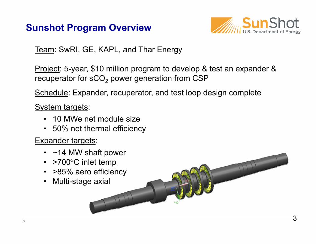
Team: SwRI, GE, KAPL, and Thar Energy
Project: 5-year, $10 million program to develop & test an expander & recuperator for sCO2 power generation from CSP
Schedule: Expander, recuperator, and test loop design complete
System targets:
Expander targets:
• 10 MWe net module size• 50% net thermal efficiency
• ~14 MW shaft power• >700C inlet temp• >85% aero efficiency• Multi-stage axial
Sunshot Program Overview
3

4
0.01
0.1
1
10
100
1000
Vapor Pressure(bar)
Vapor Density(kg/m3)
CO2
H2O2,000x 10,000x
20 MW steam turbine 14 MW sCO2 turbine
Vapor properties at 25C (77F) condenser
150 lb rotor7” rotor tip diameter27,000 rpm
Motivation for sCO2 Cycles over Steam
4
5
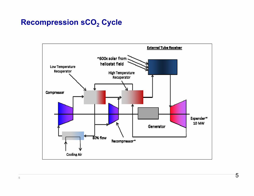
Recompression sCO2 Cycle
5
6
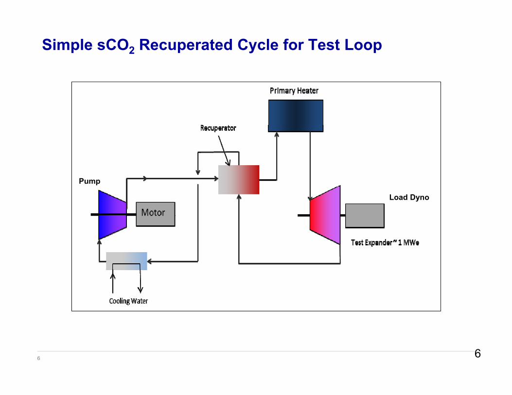
Simple sCO2 Recuperated Cycle for Test Loop
Pump
Load Dyno
6

7
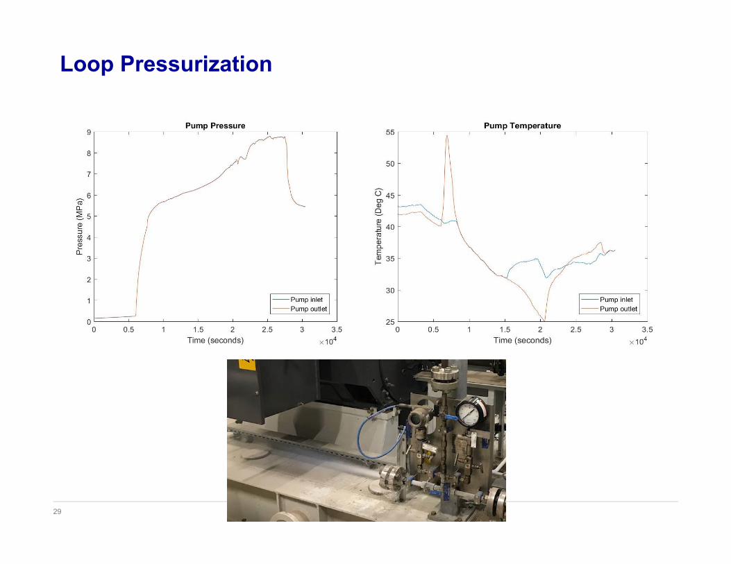
Loop Operating Conditions
Component T out, °C (°F) P out, bar (psi) Flow, kg/s (lb/s)
Pump 29.22 (84.60) 255.0 (3698) 9.910 (21.85)Recuperator-
Heat 470.0 (878.0) 252.3 (3659)8.410 (18.54)Heater 715.0 (1319) 250.9 (3639)
Expander 685.7 (1266) 86 (1247)Recuperator-
Cool 79.58 (175.2) 84 (1218)9.910 (21.85)
PreCooler 10.00 (50.00) 83 (1204)
7

8
Work has been divided into three phases that emulate development process from TRL3 to TRL6
Phase I – Turbomachinery, heat exchanger, and flow loop design (24 months)
Phase II – Component fabrication and test loop commissioning (33 months)
Phase III – Performance and endurance testing (6 months)
Project Schedule
8

9
Nozzle Casing – Rough Machine
Machining, welding, and heat treat complete
9
10
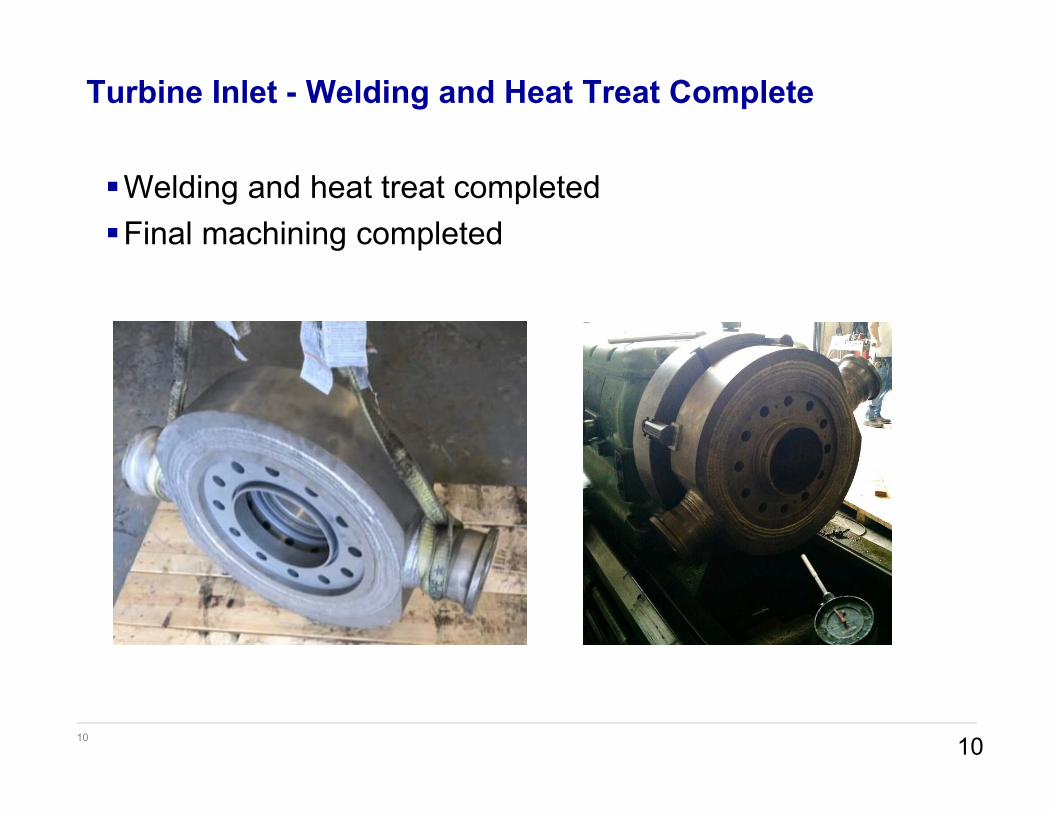
Turbine Inlet - Welding and Heat Treat Complete
10
Welding and heat treat completedFinal machining completed
11
Turbine Key Achievements
Largest scale, highest temperature SCO2 expander developed to dateEmploys industrial bearings and seals which can be scaled
to utility scaleOne-piece rotor manufacturing developed to eliminate blade
to rotor attachmentShrouded blades maintain highest efficiencyRotordynamic design to accommodate high density gas and
high speedCasting issues overcome with a fabricated case design
11
12 12
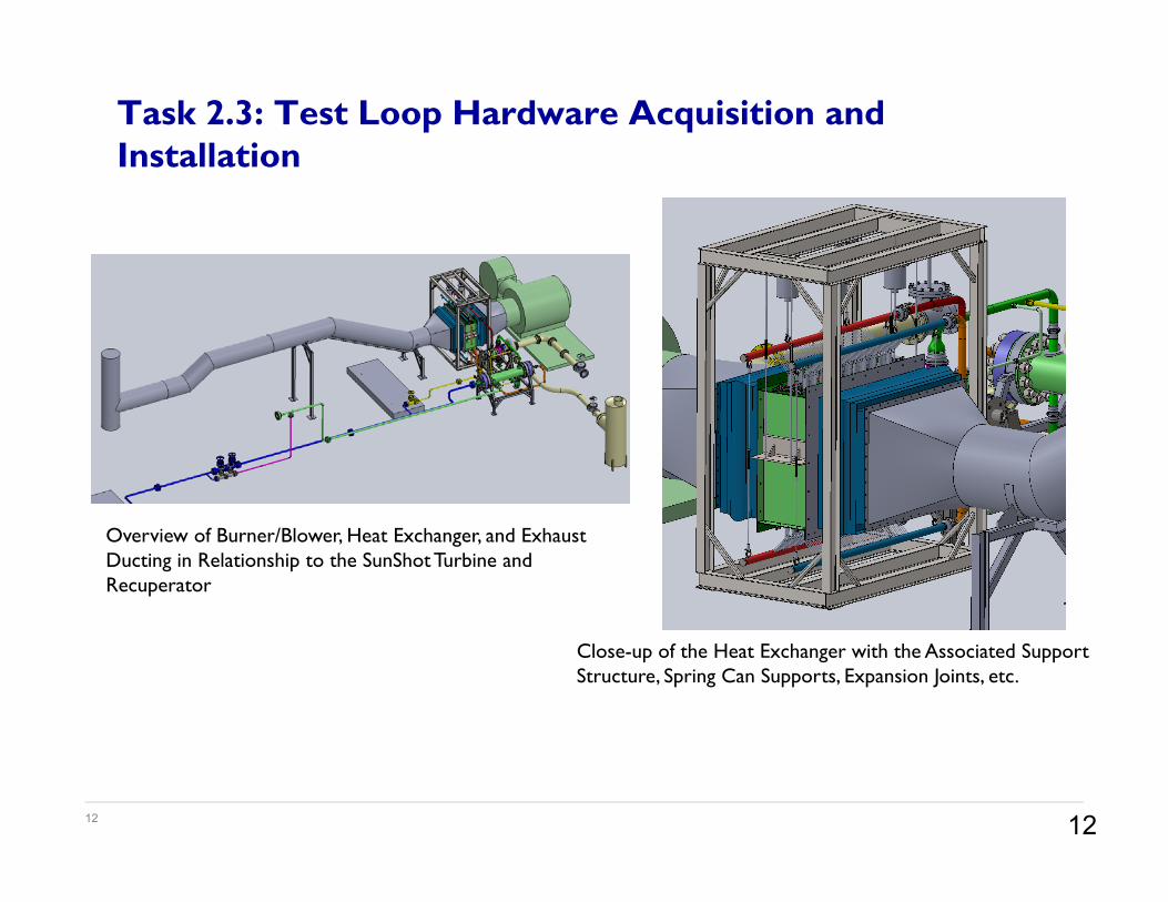
Task 2.3: Test Loop Hardware Acquisition and Installation
Overview of Burner/Blower, Heat Exchanger, and Exhaust Ducting in Relationship to the SunShot Turbine and Recuperator
Close-up of the Heat Exchanger with the Associated Support Structure, Spring Can Supports, Expansion Joints, etc.
13
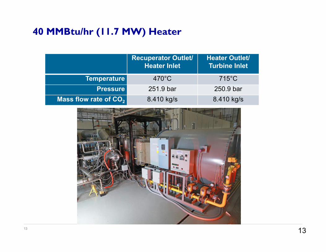
40 MMBtu/hr (11.7 MW) Heater
13
Recuperator Outlet/Heater Inlet
Heater Outlet/Turbine Inlet
Temperature 470°C 715°CPressure 251.9 bar 250.9 bar
Mass flow rate of CO2 8.410 kg/s 8.410 kg/s
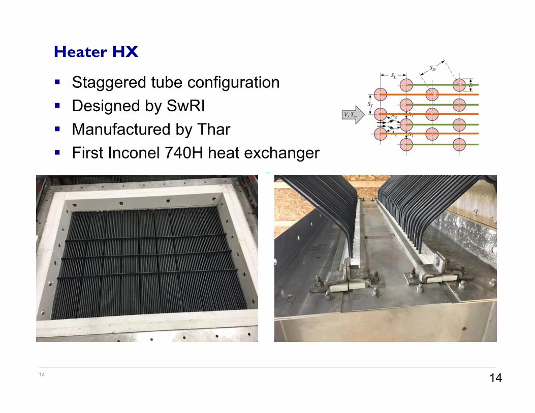
14
Staggered tube configuration Designed by SwRI Manufactured by Thar First Inconel 740H heat exchanger
Heater HX
14
15
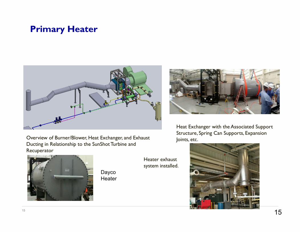
Primary Heater
Overview of Burner/Blower, Heat Exchanger, and Exhaust Ducting in Relationship to the SunShot Turbine and Recuperator
Heat Exchanger with the Associated Support Structure, Spring Can Supports, Expansion Joints, etc.
Dayco Heater
Heater exhaust system installed.
15
16
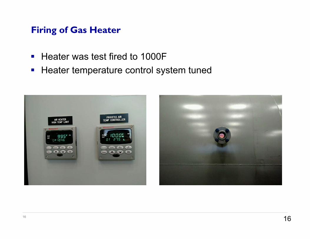
Heater was test fired to 1000F Heater temperature control system tuned
Firing of Gas Heater
16
17
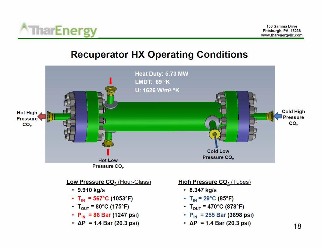
Milestone: Delivery of 5-MWt compact recuperator and performance qualification testing to demonstrate that performance specifications are met.
Completion Target Metrics:– Test unit size 50-kW scale up 100:1 for Phase 3.– Capacity (% of design) = Design goal is minimum of 80% of 35
MW/m3 (i.e., 27 MW/m3). – Pressure drop (% of design) < 1.5 times of bench-scale
performance– Cost (% of design) < Goal is not more than 1.5 times $50/kW (i.e.,
no more than $75/kW)
Thar Recuperator Development
17
18 1818
19
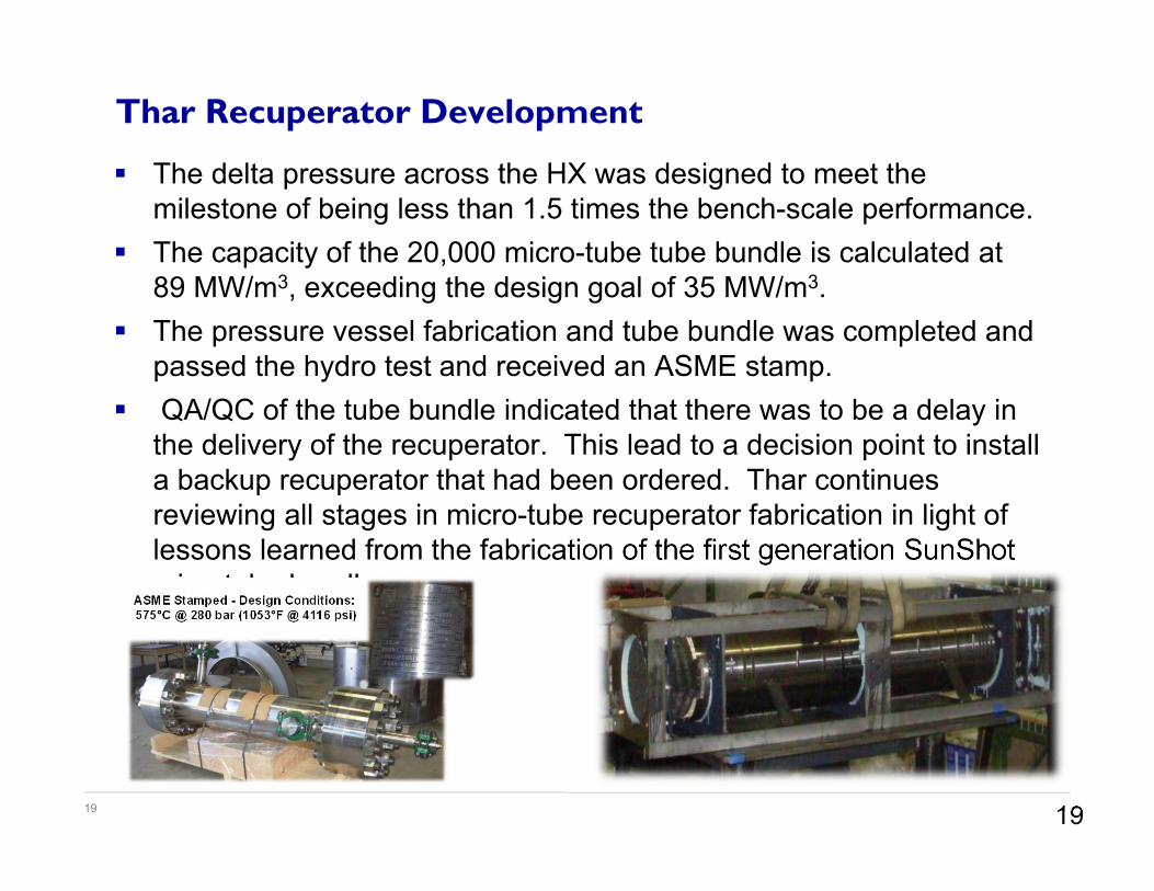
The delta pressure across the HX was designed to meet the milestone of being less than 1.5 times the bench-scale performance.
The capacity of the 20,000 micro-tube tube bundle is calculated at 89 MW/m3, exceeding the design goal of 35 MW/m3.
The pressure vessel fabrication and tube bundle was completed and passed the hydro test and received an ASME stamp.
QA/QC of the tube bundle indicated that there was to be a delay in the delivery of the recuperator. This lead to a decision point to install a backup recuperator that had been ordered. Thar continues reviewing all stages in micro-tube recuperator fabrication in light of lessons learned from the fabrication of the first generation SunShot microtube bundle.
Thar Recuperator Development
19
20
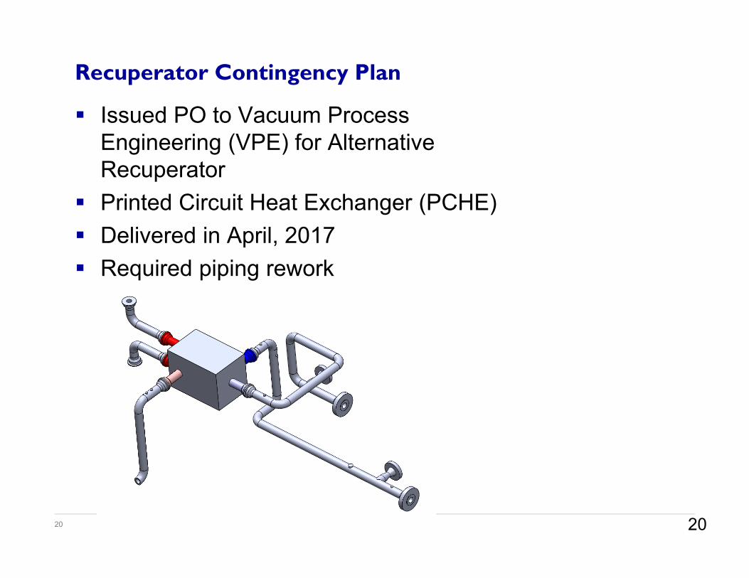
Issued PO to Vacuum Process Engineering (VPE) for Alternative Recuperator
Printed Circuit Heat Exchanger (PCHE) Delivered in April, 2017 Required piping rework
Recuperator Contingency Plan
20
21
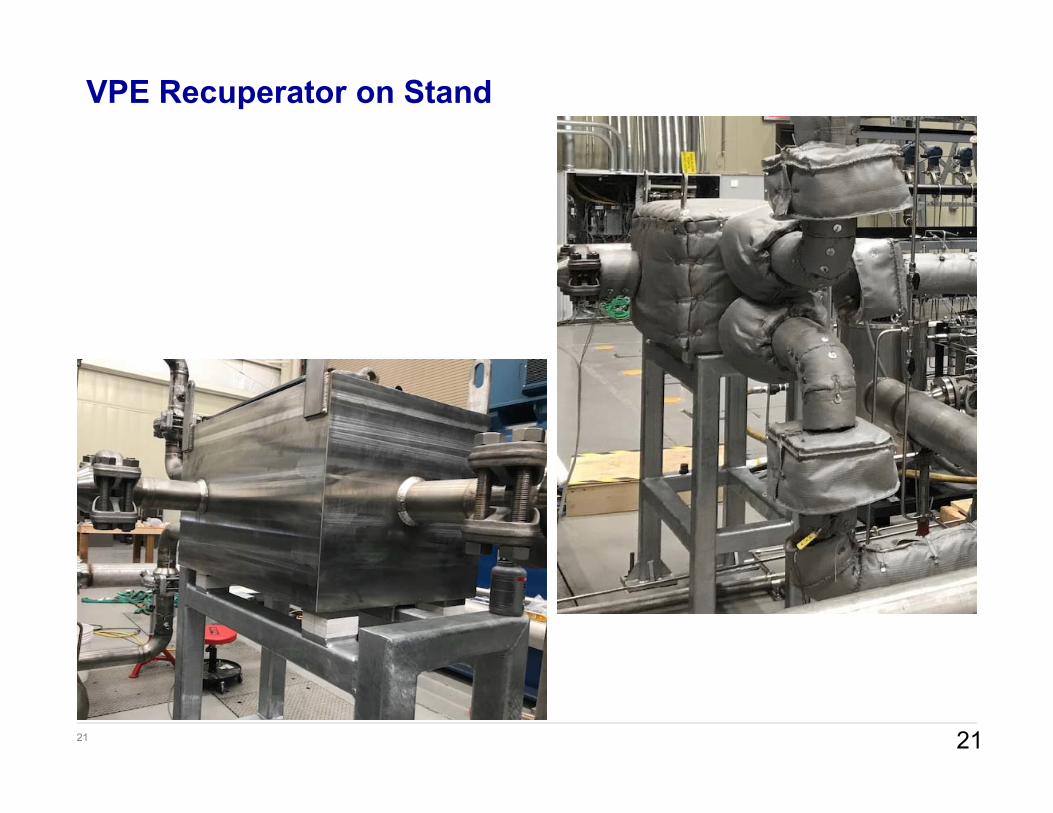
VPE Recuperator on Stand
21

22
Pump Commissioning Test
• Loop pressure checked• Pump commissioning complete• Pump spun at low speed
22
23
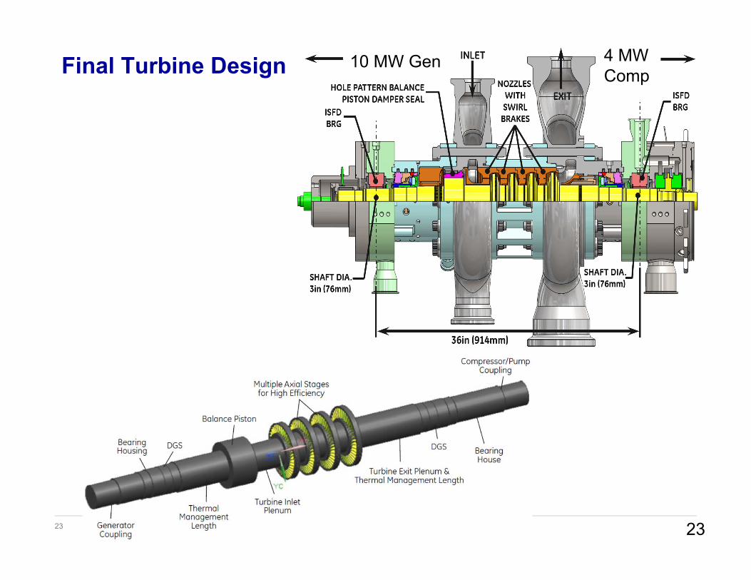
Final Turbine Design
23
10 MW Gen 4 MW Comp
24
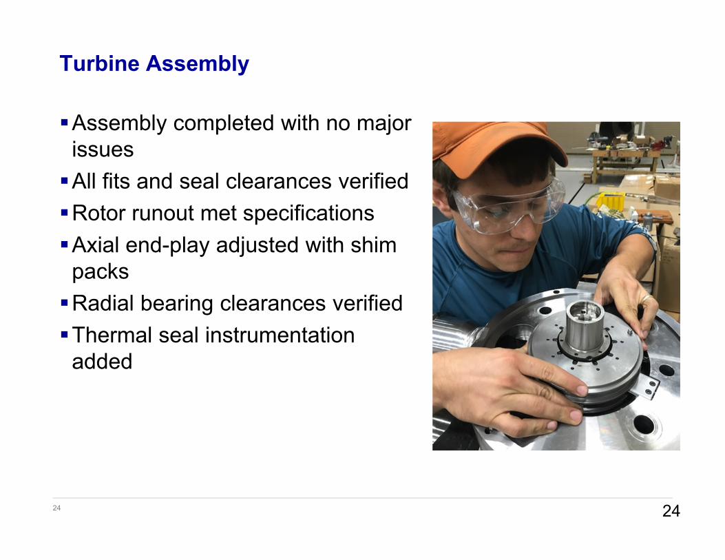
Turbine Assembly
Assembly completed with no major issuesAll fits and seal clearances verifiedRotor runout met specificationsAxial end-play adjusted with shim
packsRadial bearing clearances verifiedThermal seal instrumentation
added
24

25
Turbine Assembly Completed
Turbine assembled and installed on test standConnections made to turbine in
this order:– Large piping– Small piping– Lube oil supply and drain– Instrumentation
Dynamometer not installed for initial commissioning tests
25
26
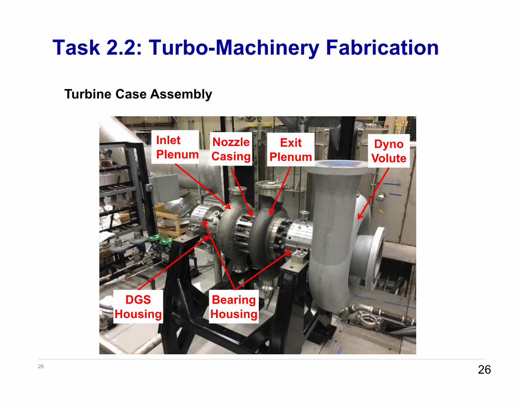
Task 2.2: Turbo-Machinery Fabrication
Turbine Case Assembly
26
NozzleCasing
InletPlenum
ExitPlenum
DynoVolute
DGSHousing
BearingHousing
27
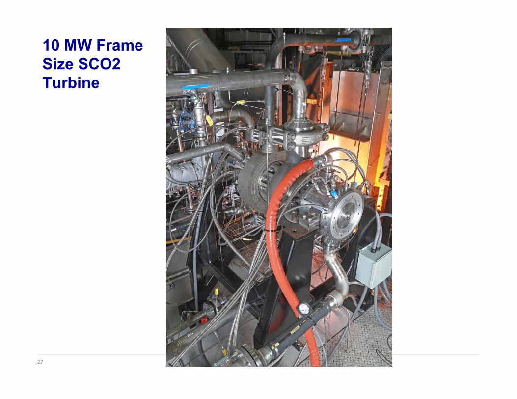
10 MW Frame Size SCO2 Turbine

28
Test Loop Components
Recuperator
IN740H Piping HeaterDry Gas
Seal Panel
Lube Oil Drain
Lube Oil Supply
IN625 Piping
28
29
Loop Pressurization
30
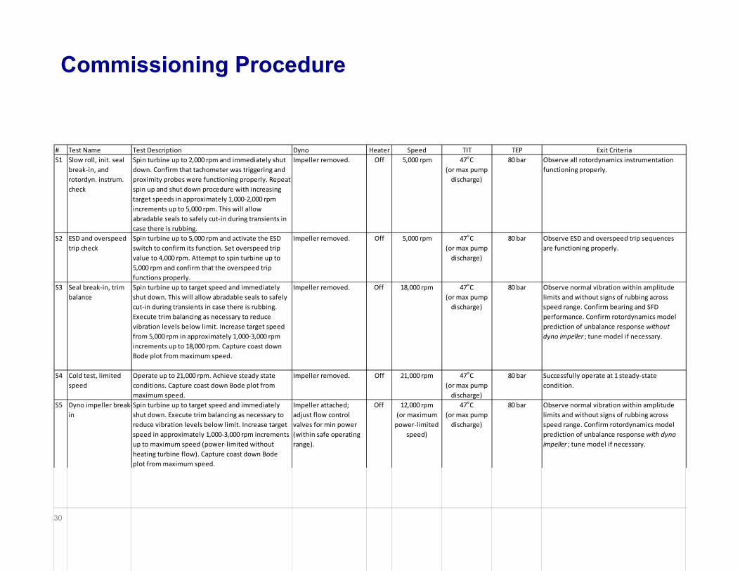
Commissioning Procedure
# Test Name Test Description Dyno Heater Speed TIT TEP Exit CriteriaS1 Slow roll, init. seal
break‐in, and rotordyn. instrum. check
Spin turbine up to 2,000 rpm and immediately shut down. Confirm that tachometer was triggering and proximity probes were functioning properly. Repeat spin up and shut down procedure with increasing target speeds in approximately 1,000‐2,000 rpm increments up to 5,000 rpm. This will allow abradable seals to safely cut‐in during transients in case there is rubbing.
Impeller removed. Off 5,000 rpm 47°C(or max pump discharge)
80 bar Observe all rotordynamics instrumentation functioning properly.
S2 ESD and overspeed trip check
Spin turbine up to 5,000 rpm and activate the ESD switch to confirm its function. Set overspeed trip value to 4,000 rpm. Attempt to spin turbine up to 5,000 rpm and confirm that the overspeed trip functions properly.
Impeller removed. Off 5,000 rpm 47°C(or max pump discharge)
80 bar Observe ESD and overspeed trip sequences are functioning properly.
S3 Seal break‐in, trim balance
Spin turbine up to target speed and immediately shut down. This will allow abradable seals to safely cut‐in during transients in case there is rubbing. Execute trim balancing as necessary to reduce vibration levels below limit. Increase target speed from 5,000 rpm in approximately 1,000‐3,000 rpm increments up to 18,000 rpm. Capture coast down Bode plot from maximum speed.
Impeller removed. Off 18,000 rpm 47°C(or max pump discharge)
80 bar Observe normal vibration within amplitude limits and without signs of rubbing across speed range. Confirm bearing and SFD performance. Confirm rotordynamics model prediction of unbalance response without dyno impeller ; tune model if necessary.
S4 Cold test, limited speed
Operate up to 21,000 rpm. Achieve steady state conditions. Capture coast down Bode plot from maximum speed.
Impeller removed. Off 21,000 rpm 47°C(or max pump discharge)
80 bar Successfully operate at 1 steady‐state condition.
S5 Dyno impeller break‐in
Spin turbine up to target speed and immediately shut down. Execute trim balancing as necessary to reduce vibration levels below limit. Increase target speed in approximately 1,000‐3,000 rpm increments up to maximum speed (power‐limited without heating turbine flow). Capture coast down Bode plot from maximum speed.
Impeller attached; adjust flow control valves for min power (within safe operating range).
Off 12,000 rpm(or maximum power‐limited
speed)
47°C(or max pump discharge)
80 bar Observe normal vibration within amplitude limits and without signs of rubbing across speed range. Confirm rotordynamics model prediction of unbalance response with dyno impeller ; tune model if necessary.
31
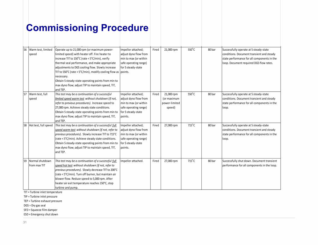
Commissioning Procedureplot from maximum speed.
S6 Warm test, limited speed
Operate up to 21,000 rpm (or maximum power‐limited speed) with heater off. Fire heater to increase TIT to 150°C (rate < 5°C/min), verify thermal seal performance, and make appropriate adjustments to DGS cooling flow. Slowly increase TIT to 550°C (rate < 5°C/min), modify cooling flow as necessary.Obtain 5 steady‐state operating points from min to max dyno flow; adjust TIP to maintain speed, TIT, and TEP.
Impeller attached; adjust dyno flow from min to max (or within safe operating range) for 5 steady‐state points.
Fired 21,000 rpm 550°C 80 bar Successfully operate at 5 steady‐state conditions. Document transient and steady state performance for all components in the loop. Document required DGS flow rates.
S7 Warm test, full speed
This test may be a continuation of a successful limited speed warm test without shutdown (if not, refer to previous procedures). Increase speed to 27,000 rpm. Achieve steady state conditions.Obtain 5 steady‐state operating points from min to max dyno flow; adjust TIP to maintain speed, TIT, and TEP.
Impeller attached; adjust dyno flow from min to max (or within safe operating range) for 5 steady‐state points.
Fired 21,000 rpm(or maximum power‐limited
speed)
550°C 80 bar Successfully operate at 5 steady‐state conditions. Document transient and steady state performance for all components in the loop.
S8 Hot test, full speed This test may be a continuation of a successful full speed warm test without shutdown (if not, refer to previous procedures). Slowly increase TIT to 715°C (rate < 5°C/min). Achieve steady state conditions.Obtain 5 steady‐state operating points from min to max dyno flow; adjust TIP to maintain speed, TIT, and TEP.
Impeller attached; adjust dyno flow from min to max (or within safe operating range) for 5 steady‐state points.
Fired 27,000 rpm 715°C 80 bar Successfully operate at 5 steady‐state conditions. Document transient and steady state performance for all components in the loop.
S9 Normal shutdown from max TIT
This test may be a continuation of a successful full speed hot test without shutdown (if not, refer to previous procedures). Slowly decrease TIT to 200°C (rate < 5°C/min). Turn off burner, but maintain air blower flow. Reduce speed to 5,000 rpm. After heater air exit temperature reaches 150°C, stop turbine and pump.
Impeller attached. Fired 27,000 rpm 715°C 80 bar Successfully shut down. Document transient performance for all components in the loop.
TIT = Turbine inlet temperatureTIP = Turbine inlet pressureTEP = Turbine exhaust pressureDGS = Dry gas sealSFD = Squeeze film damperESD = Emergency shut down
32
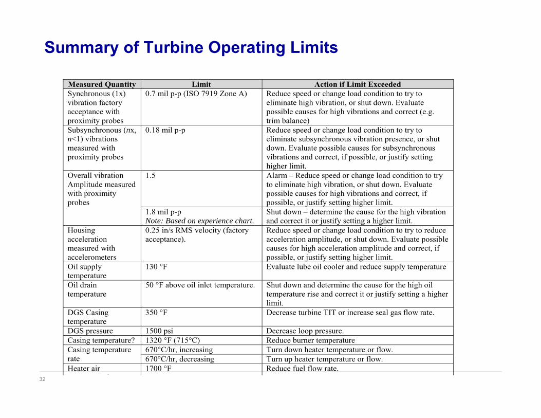
Summary of Turbine Operating Limits
Measured Quantity Limit Action if Limit Exceeded Synchronous (1x) vibration factory acceptance with proximity probes
0.7 mil p-p (ISO 7919 Zone A) Reduce speed or change load condition to try to eliminate high vibration, or shut down. Evaluate possible causes for high vibrations and correct (e.g. trim balance)
Subsynchronous (nx, n<1) vibrations measured with proximity probes
0.18 mil p-p Reduce speed or change load condition to try to eliminate subsynchronous vibration presence, or shut down. Evaluate possible causes for subsynchronous vibrations and correct, if possible, or justify setting higher limit.
Overall vibration Amplitude measured with proximity probes
1.5 Alarm – Reduce speed or change load condition to try to eliminate high vibration, or shut down. Evaluate possible causes for high vibrations and correct, if possible, or justify setting higher limit.
1.8 mil p-p Note: Based on experience chart.
Shut down – determine the cause for the high vibration and correct it or justify setting a higher limit.
Housing acceleration measured with accelerometers
0.25 in/s RMS velocity (factory acceptance).
Reduce speed or change load condition to try to reduce acceleration amplitude, or shut down. Evaluate possible causes for high acceleration amplitude and correct, if possible, or justify setting higher limit.
Oil supply temperature
130 °F Evaluate lube oil cooler and reduce supply temperature
Oil drain temperature
50 °F above oil inlet temperature. Shut down and determine the cause for the high oil temperature rise and correct it or justify setting a higher limit.
DGS Casing temperature
350 °F Decrease turbine TIT or increase seal gas flow rate.
DGS pressure 1500 psi Decrease loop pressure. Casing temperature? 1320 °F (715°C) Reduce burner temperature Casing temperature rate
670°C/hr, increasing Turn down heater temperature or flow. 670°C/hr, decreasing Turn up heater temperature or flow.
Heater air ?
1700 °F Reduce fuel flow rate.
33
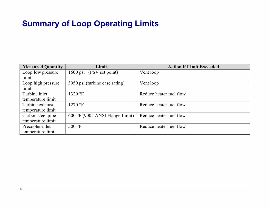
Summary of Loop Operating Limits
Measured Quantity Limit Action if Limit Exceeded Loop low pressure limit
1600 psi (PSV set point) Vent loop
Loop high pressure limit
3950 psi (turbine case rating) Vent loop
Turbine inlet temperature limit
1320 °F Reduce heater fuel flow
Turbine exhaust temperature limit
1270 °F Reduce heater fuel flow
Carbon steel pipe temperature limit
600 °F (900# ANSI Flange Limit) Reduce heater fuel flow
Precooler inlet temperature limit
500 °F Reduce heater fuel flow
34
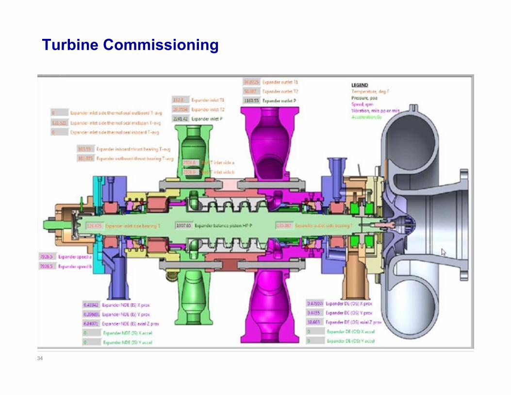
Turbine Commissioning
35
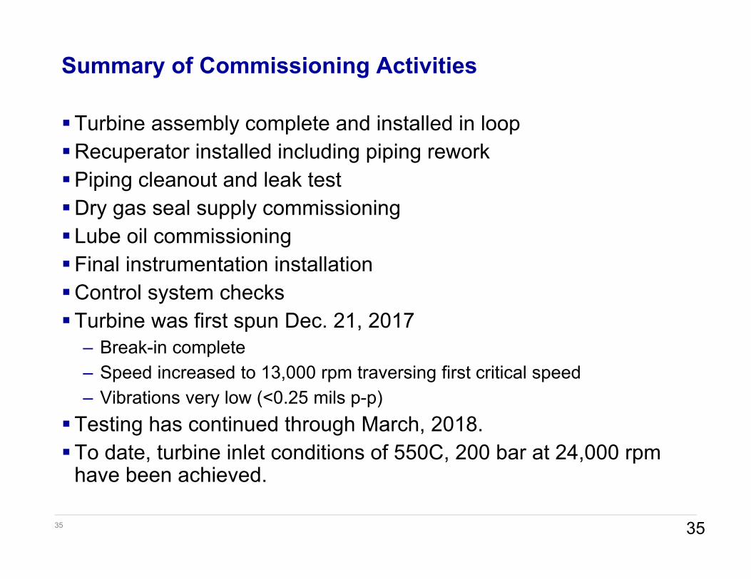
Summary of Commissioning Activities
Turbine assembly complete and installed in loopRecuperator installed including piping reworkPiping cleanout and leak test Dry gas seal supply commissioningLube oil commissioningFinal instrumentation installationControl system checksTurbine was first spun Dec. 21, 2017
– Break-in complete– Speed increased to 13,000 rpm traversing first critical speed– Vibrations very low (<0.25 mils p-p)
Testing has continued through March, 2018.To date, turbine inlet conditions of 550C, 200 bar at 24,000 rpm
have been achieved.
35

energy.gov/sunshotenergy.gov/sunshot
Questions???
Discussion
36