commissioning instruction for drive … instruction replaces am-11.65.015 v3f25 commissioning...
TRANSCRIPT
V3F25/18 driveInstallation Instruction
COMMISSIONING INSTRUCTION FOR DRIVE SYSTEMS V3F25AND V3F18
TABLE OF CONTENTS
1 GENERAL . . . . . . . . . . . . . . . . . . . . . . . . . . . . . . . . . . . . . . . . . . . . . . . . . . . . . . . . . . . . . . . 21.1 Validity of the instruction . . . . . . . . . . . . . . . . . . . . . . . . . . . . . . . . . . . . . . . . . . . . . . . 21.2 Related documents . . . . . . . . . . . . . . . . . . . . . . . . . . . . . . . . . . . . . . . . . . . . . . . . . . . 31.3 Abbreviations. . . . . . . . . . . . . . . . . . . . . . . . . . . . . . . . . . . . . . . . . . . . . . . . . . . . . . . . 3
2 SAFETY . . . . . . . . . . . . . . . . . . . . . . . . . . . . . . . . . . . . . . . . . . . . . . . . . . . . . . . . . . . . . . . . . 42.1 General working safety . . . . . . . . . . . . . . . . . . . . . . . . . . . . . . . . . . . . . . . . . . . . . . . . 42.2 Electrical working safety . . . . . . . . . . . . . . . . . . . . . . . . . . . . . . . . . . . . . . . . . . . . . . . 4
3 INTRODUCTION OF COMPONENTS . . . . . . . . . . . . . . . . . . . . . . . . . . . . . . . . . . . . . . . . . . 53.1 Common boards . . . . . . . . . . . . . . . . . . . . . . . . . . . . . . . . . . . . . . . . . . . . . . . . . . . . . 53.2 Panels in the elevator shaft . . . . . . . . . . . . . . . . . . . . . . . . . . . . . . . . . . . . . . . . . . . . . 83.3 Panels in the machine room . . . . . . . . . . . . . . . . . . . . . . . . . . . . . . . . . . . . . . . . . . . . 9
4 INITIAL COMMISSIONING OF THE MACHINE (WITHOUT ROPES) . . . . . . . . . . . . . . . . . .114.1 Prerequisites and preparations . . . . . . . . . . . . . . . . . . . . . . . . . . . . . . . . . . . . . . . . . .114.2 Setting parameters . . . . . . . . . . . . . . . . . . . . . . . . . . . . . . . . . . . . . . . . . . . . . . . . . . 144.3 Setting the input information . . . . . . . . . . . . . . . . . . . . . . . . . . . . . . . . . . . . . . . . . . . 174.4 Initial setting of the resolver angle. . . . . . . . . . . . . . . . . . . . . . . . . . . . . . . . . . . . . . . 19
5 COMMISSIONING OF THE MACHINE AFTER ROPING . . . . . . . . . . . . . . . . . . . . . . . . . . 215.1 LWD setup. . . . . . . . . . . . . . . . . . . . . . . . . . . . . . . . . . . . . . . . . . . . . . . . . . . . . . . . . 215.2 Repeating the resolver angle setting. . . . . . . . . . . . . . . . . . . . . . . . . . . . . . . . . . . . . 245.3 Shaft setup . . . . . . . . . . . . . . . . . . . . . . . . . . . . . . . . . . . . . . . . . . . . . . . . . . . . . . . . 245.4 Fine tuning the resolver angle . . . . . . . . . . . . . . . . . . . . . . . . . . . . . . . . . . . . . . . . . . 25
6 FINE ADJUSTMENTS . . . . . . . . . . . . . . . . . . . . . . . . . . . . . . . . . . . . . . . . . . . . . . . . . . . . . 266.1 Drive adjustments and checks (speed control) . . . . . . . . . . . . . . . . . . . . . . . . . . . . . 266.2 Starting . . . . . . . . . . . . . . . . . . . . . . . . . . . . . . . . . . . . . . . . . . . . . . . . . . . . . . . . . . . 276.3 Jerky start or roll back . . . . . . . . . . . . . . . . . . . . . . . . . . . . . . . . . . . . . . . . . . . . . . . . 276.4 Stopping (final rounding to the floor) . . . . . . . . . . . . . . . . . . . . . . . . . . . . . . . . . . . . . 296.5 Testing with heavy loads . . . . . . . . . . . . . . . . . . . . . . . . . . . . . . . . . . . . . . . . . . . . . . 306.6 Balance measurement in elevators with V3F18 drive and MAP panel . . . . . . . . . . . 316.7 Balance measurement in elevators with V3F25 drive . . . . . . . . . . . . . . . . . . . . . . . . 32
7 APPROVALS AND VERSION HISTORY . . . . . . . . . . . . . . . . . . . . . . . . . . . . . . . . . . . . . . . 33APPENDIX A. Returning the initial settings . . . . . . . . . . . . . . . . . . . . . . . . . . . . . . . . . . . . . . . . . . 34APPENDIX B. Buzzer warnings. . . . . . . . . . . . . . . . . . . . . . . . . . . . . . . . . . . . . . . . . . . . . . . . . . . 35APPENDIX C. Troubleshooting . . . . . . . . . . . . . . . . . . . . . . . . . . . . . . . . . . . . . . . . . . . . . . . . . . . 36APPENDIX D. Parameter table 779980. . . . . . . . . . . . . . . . . . . . . . . . . . . . . . . . . . . . . . . . . . . . . 41
© 2004 KONE Corporation AM-11.65.020All rights reserved. 1 (42) (E) 2004-01-08
V3F25/18 driveInstallation Instruction
1 GENERAL
1.1 Validity of the instruction
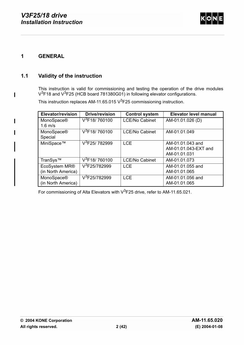
This instruction is valid for commissioning and testing the operation of the drive modulesV3F18 and V3F25 (HCB board 781380G01) in following elevator configurations.
This instruction replaces AM-11.65.015 V3F25 commissioning instruction.
For commissioning of Alta Elevators with V3F25 drive, refer to AM-11.65.021.
Elevator/revision Drive/revision Control system Elevator level manualMonoSpace® 1.6 m/s
V3F18/ 760100 LCE/No Cabinet AM-01.01.026 (D)
MonoSpace® Special
V3F18/ 760100 LCE/No Cabinet AM-01.01.049
MiniSpace™ V3F25/ 782999 LCE AM-01.01.043 andAM-01.01.043-EXT andAM-01.01.031
TranSys™ V3F18/ 760100 LCE/No Cabinet AM-01.01.073EcoSystem MR®(in North America)
V3F25/782999 LCE AM-01.01.055 andAM-01.01.065
MonoSpace®(in North America)
V3F25/782999 LCE AM-01.01.056 andAM-01.01.065
© 2004 KONE Corporation AM-11.65.020All rights reserved. 2 (42) (E) 2004-01-08

V3F25/18 driveInstallation Instruction
1.2 Related documents
Refer to the elevator level instructions for the commissioning prerequisites, safety chainchecking, setting the non-drive features, special features and especially for the workingsafety.
• AM-01.03.001 Use of fall arrest systems on elevator construction and modernisation sites• AM-01.03.002 Take 5 - Electrical Safety When Working on Elevators• Elevator level instructions• Parameter list 779980• Brake adjustment instructions:
AM-04.08.021 for MX10AM-04.08.022 for MX18AM-04.08.023 for MX20AM-04.08.024 for MX32
• AM-11.65.021 Alta / V3F25 and V3F25MLB commissioning instruction• AS-11.65.001 Instruction to replace V3F25 module• AS-11.65.020 Replacement Instruction for HCB board• AS-11.65.008 Repair Instruction for V3F25MLB drive system• AS-11.65.005 Repair Instruction for V3F18 drive system• AR-11.65.009 Spare Parts Manual for V3F18 Drive• AR-11.65.011 Spare Parts Manual for V3F25MLB Drive• AR-11.65.008 Spare Parts Manual for V3F25 Drive
1.3 Abbreviations
CMB = Current Measurement Board
EBD = Emergency Battery Drive
EPD = Emergency Power Drive
LBR = Line Bridge
LWD = Load Weighing Device
MAP = Maintenance Access Panel
MLB = Modulated Line Bridge
NTS = Normal Terminal Slowdown
RDF = Recall Drive Feature (In North America machine room inspection drive is used insteadof RDF drive.)
© 2004 KONE Corporation AM-11.65.020All rights reserved. 3 (42) (E) 2004-01-08
V3F25/18 driveInstallation Instruction
2 SAFETY
2.1 General working safety
This instruction is used in accordance with several elevator configurations. You must read thesafety instructions in each elevator level installation manual to ensure your working safety.
Take special care when working on the car roof or other position where is danger of falling.
Refer to AM-01.03.001 use of fall arrest systems on elevator construction and modernisationsites.
When there is any doubt of the correct working method, ask your superiors.
2.2 Electrical working safety
Read carefully the electrical working safety instructions in the corresponding elevator levelmanual to ensure the correct switching off and locking methods in each elevator.
Pay special attention when working on the car roof if there are powered parts in your workingarea.
Refer to AM-01.03.002 "Take 5 - Electrical Safety When Working on Elevators".
The Take 5 safety initiative is designed for installation, servicing, maintenance andmodernisation work done on elevators. The AM describes safe working procedures forpreventing electric shock and other possible hazards from unwanted movement of equipmentto yourself and others when working on elevators. Read and follow all related instructions andcomply with your local safety codes and rules.
The following 5 steps must be taken in the specified order unless there are essential reasonsfor doing otherwise:
Take 5 steps to ensure electrical safety:
1. Disconnect power supply completely.2. Secure power supply against re-connection.3. Verify that the installation is de-energised.4. Check the requirements for earthing in special circumstances. (This operation may only
be carried out by qualified personnel in co-operation with the person responsible for thebuilding electrification who must ensure that the technique can be safely employed in thissituation.)
5. Provide protection against adjacent live parts.
© 2004 KONE Corporation AM-11.65.020All rights reserved. 4 (42) (E) 2004-01-08

V3F25/18 driveInstallation Instruction
3 INTRODUCTION OF COMPONENTS
3.1 Common boards
3.1.1 HCB board (781380G01)
X3
V11
F1
V12
XB1
XD1
XD5
XR1 RDIR
POS12V
TTR
HARM3
TTS
GND2
B3
XM1
R525
R526
R527
XI1
POS5V
NEG12V
TTT
TAC
MEAS
XSR1
TPD
UREF2
RSTEST
WRL WRH
NEG10V
XM2
VREFZ3
Z2
Z4
AGND2
XG1
TP0 TP1
S5TORQ
MXTORQ
AGND
GND
POWER
3
SIN-DATA
4
SAFETY RELAY
INVERTER
LIFT
CO
NTR
OLL
ER
MLB INTERFACERESOLVER
123
TACHO
2
LOW (EVEN)
KONE
XW1
XLG
1
CURRENTMAP INTERFACE
TACHO
RTT
RTR
RTS
V3F25 HCB
1
THERMALSWITCH
LBE
BRAKE
HIGH (ODD)
TXD
INSP. DRIVE
DOWN STARTUP START
HALF SPEED
MAIN CONTRPOLTPOL
RED. SPEED
RXDPICKUP
SP.LIMITBRAKE
NORMAL RUNRELEVELLING
77S
61U77N
61N77U
POW
ER
MC
SUP
PCB 781383H02
TACHO INPUT
XN1
MOTOR
NTS INTERFACE
TEMPERATURE
F2LWD
XWLOADWEIGHING
LBR
1019831.wmf
© 2004 KONE Corporation AM-11.65.020All rights reserved. 5 (42) (E) 2004-01-08
V3F25/18 driveInstallation Instruction
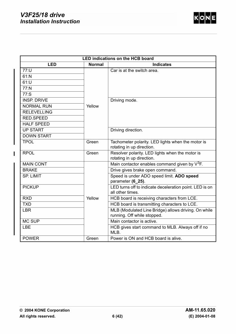
LED indications on the HCB boardLED Normal Indicates
77:U Car is at the switch area. 61:N61:U77:N77:SINSP. DRIVE Driving mode.NORMAL RUN YellowRELEVELLINGRED.SPEEDHALF SPEEDUP START Driving direction.DOWN STARTTPOL Green Tachometer polarity. LED lights when the motor is
rotating in up direction.RPOL Green Resolver polarity. LED lights when the motor is
rotating in up direction.MAIN CONT Main contactor enables command given by V3F.BRAKE Drive gives brake open command.SP. LIMIT Speed is under ADO speed limit. ADO speed
parameter (6_25).PICKUP LED turns off to indicate deceleration point. LED is on
all other times.RXD Yellow HCB board is receiving characters from LCE.TXD HCB board is transmitting characters to LCE.LBR MLB (Modulated Line Bridge) allows driving. On while
running. Off while stopped.MC SUP Main contactor is active.LBE HCB gives start command to MLB. Always off if no
MLB.POWER Green Power is ON and HCB board is alive.
© 2004 KONE Corporation AM-11.65.020All rights reserved. 6 (42) (E) 2004-01-08

V3F25/18 driveInstallation Instruction
3.1.2 Inverter board (725800G01)
LED indications on the inverter boardLED Note Normal Indicates
DANGER Yellow High voltage exists in the intermediate circuit.SCL Active approx. 8
sec. also after power up
Red Overcurrent in the motor.BRSL Red Problem in the braking transistor circuit.DCS Red DC over or under voltage.BRE Not a fault LED Red Resistor braking is on.
1019832.wmf
XD5
X6X7G
X7F
X7E
X7D
X7C
X7B
X7A
BRF
DANGER
BRE
SCLBRSLDCS
BRF
-300
V
VCC
DG
ND
MBEDGND
SUP
© 2004 KONE Corporation AM-11.65.020All rights reserved. 7 (42) (E) 2004-01-08

V3F25/18 driveInstallation Instruction
3.2 Panels in the elevator shaft
Panels in the elevator shaft in the
MonoSpace® elevators with V3F18 drive
Shaft electrification panel in the MonoSpace®
Special and TranSys™ elevators
V3F18 drive panel
1. Drive panel (385) 1. Drive panel (385) 1. CMB board (385:A3)2. LCE and optional boards
2. Main switch module 2. PCB rack3. Main switch 220:1 3. HCB board 781380G01 (385:A1)4. LCE and optional boards 4. Inverter board 725800G01(385:A2)
5. Fan (303)6. Brake control module (385:A5)7. Main contactors (201:1)8. Control voltage transformer (385:T1)1
2
1019833.wmf
1
3
2
4
P10000249.wmfP10000250.wmf
1
2
3
4
5
678
© 2004 KONE Corporation AM-11.65.020All rights reserved. 8 (42) (E) 2004-01-08

V3F25/18 driveInstallation Instruction
3.3 Panels in the machine room
MLB control panel and MLB drive panel in the MiniSpace™ elevators with V3F25 drive
Control/drive panel in MiniSpace™ elevators
1. MLB control panel 6. MLB drive panel 1. Control panel and drive panel2. Switch unit 7. V3F25 (385) 2. Power module3. RDF buttons (270) 8. MLB line bridge (386) 3. Brake resistor (306)4. Power module 9. Brake control unit (388) 4. RDF buttons (270)5. Drive panel interface module
10. Main contactor module (201:1)
5. Optional devices
11. Resistor module: charging resistor and fuse (390)
6. V3F25 (385)
12. Line filter unit (389) 7. NTS module13. NTS module 8. Brake control unit (388)
9. Main contactor module (201:1)
9
5
11
8
104
2,3
13
12
6
1021344.wmf
7
1
3
1
4
2
5
6
7
89
1021345.wmf
© 2004 KONE Corporation AM-11.65.020All rights reserved. 9 (42) (E) 2004-01-08

V3F25/18 driveInstallation Instruction
MLB control panel and MLB drive panel in the elevators in North America (MonoSpace® and
EcoSystem MR®)
Control panel and drive panel in the elevators in North America
(MonoSpace® and EcoSystem MR®)1. MLB control panel 6. MLB drive panel 1. Control panel and drive panel2. Switch unit 7. V3F25 (385) 2. Power module3. Machine room inspection drive buttons
8. MLB line bridge (386) 3. Brake resistor (306)
4. Power module 9. Brake control unit (388) 4. Machine room inspection drive buttons
5. Drive panel interface module
10. Main contactor module (201:1)
5. Switch unit
11. Resistor module: charging resistor and fuse (390)
6. V3F25 (385)
12. Line filter unit (389) 7. NTS module13. NTS module 8. Brake control unit (388)
9. Main contactor module (201:1)
1 62,3
4
5
12
11
8 7
13
9
10
1020170.w
1
9
3
6
7
8
2
1021346.wmf
4,5
© 2004 KONE Corporation AM-11.65.020All rights reserved. 10 (42) (E) 2004-01-08
V3F25/18 driveInstallation Instruction
4 INITIAL COMMISSIONING OF THE MACHINE (WITHOUT ROPES)
4.1 Prerequisites and preparations
Refer to the elevator level installation manuals for the prerequisites and preparations thateach elevator needs to have been done before commissioning of the machine.
4.1.1 Checking the mechanical obstructions
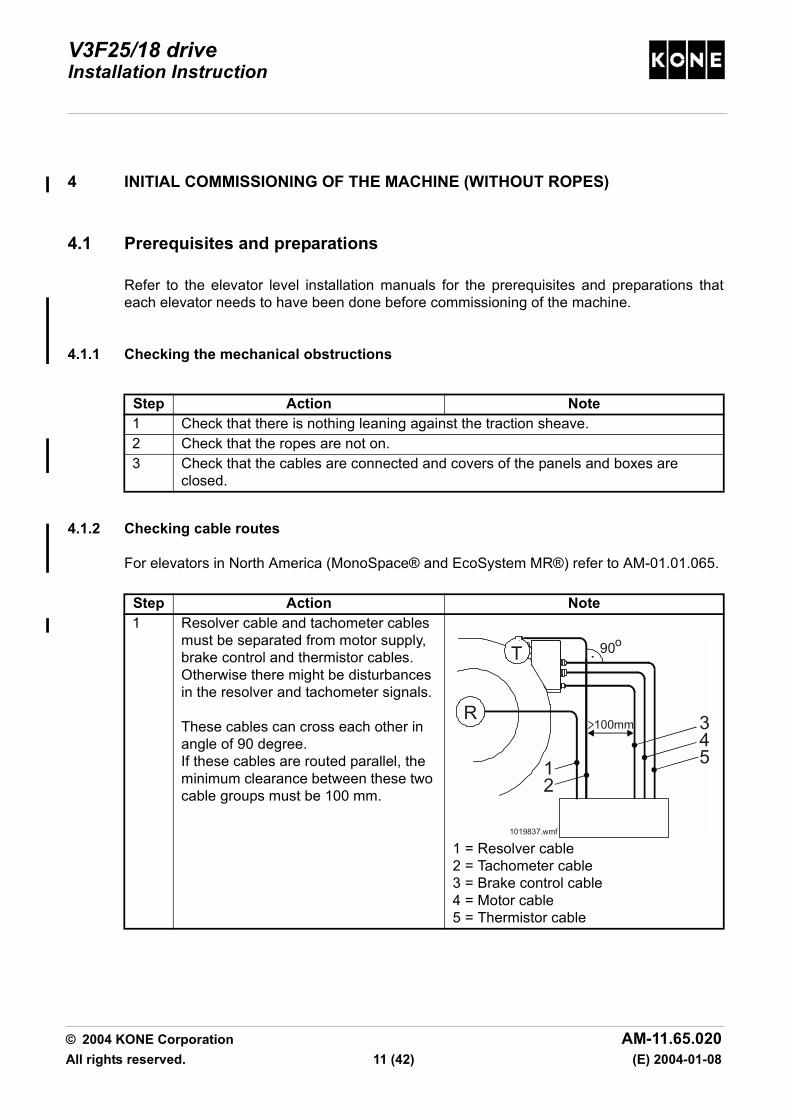
4.1.2 Checking cable routes
For elevators in North America (MonoSpace® and EcoSystem MR®) refer to AM-01.01.065.
Step Action Note1 Check that there is nothing leaning against the traction sheave.2 Check that the ropes are not on.3 Check that the cables are connected and covers of the panels and boxes are
closed.
Step Action Note1 Resolver cable and tachometer cables
must be separated from motor supply, brake control and thermistor cables. Otherwise there might be disturbances in the resolver and tachometer signals.
These cables can cross each other in angle of 90 degree.If these cables are routed parallel, the minimum clearance between these two cable groups must be 100 mm.
1 = Resolver cable 2 = Tachometer cable3 = Brake control cable4 = Motor cable5 = Thermistor cable
345
T
R
12
1019837.wmf
100mm
90o
© 2004 KONE Corporation AM-11.65.020All rights reserved. 11 (42) (E) 2004-01-08
V3F25/18 driveInstallation Instruction
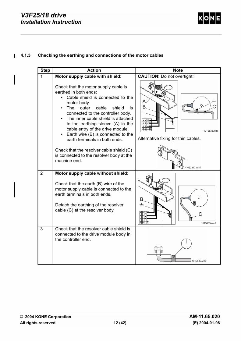
4.1.3 Checking the earthing and connections of the motor cables
Step Action Note1 Motor supply cable with shield:
Check that the motor supply cable is earthed in both ends:
• Cable shield is connected to themotor body.
• The outer cable shield isconnected to the controller body.
• The inner cable shield is attachedto the earthing sleeve (A) in thecable entry of the drive module.
• Earth wire (B) is connected to theearth terminals in both ends.
Check that the resolver cable shield (C) is connected to the resolver body at the machine end.
CAUTION! Do not overtight!
Alternative fixing for thin cables.
2 Motor supply cable without shield:
Check that the earth (B) wire of the motor supply cable is connected to the earth terminals in both ends.
Detach the earthing of the resolver cable (C) at the resolver body.
3 Check that the resolver cable shield is connected to the drive module body in the controller end.
1019838.wmf
WVU
AB C
1022317.wmf
1019839.wmf
B
C
1019840.wmf
© 2004 KONE Corporation AM-11.65.020All rights reserved. 12 (42) (E) 2004-01-08

V3F25/18 driveInstallation Instruction
4 Check that the shield of the tachometer cable is connected to the drive body.
Check that the earth wire is connected to the drive.
CAUTION!Do not connect the tachometer shielding to the earthing at the motor end.
5 Check that the shield of the brake cable is connected to the controller body.
6 Check the connection and tightness of wires in the terminals.
Refer to the wiring diagrams.
Step Action Note
XG1
1022097.wmf
© 2004 KONE Corporation AM-11.65.020All rights reserved. 13 (42) (E) 2004-01-08

V3F25/18 driveInstallation Instruction
4.2 Setting parameters
4.2.1 Entering the drive menu
4.2.2 Setting the drive parameters
All the 14 steps in the following table must always be carried out.
Step Action Note1 Ensure that the power is OFF.2 Turn the elevator to RDF (machine room inspection drive in North America).3 Turn the power ON. Refer to the elevator level installation
manual.4 Select menu 6. Come out from drive menu when you
want to drive the elevator.
Step Action Note1 Check that document identification (6_0) parameter matches the ID on
parameter list 779980 (APPENDIX).Set the elevator dependent parameters:2 Motor type (6_1) parameter Setting Motor type (6_1) parameter
turns other values to default settings for that type of motor.
3 Nominal speed (6_2) parameter4 Elevator load (6_3) parameter5 Roping (6_4) parameter6 Current sensor scaling (6_5) parameter
Set value of Current sensor scaling (5) parameter to 1 or 2 depending on the wiring on the CMB board in the drive module.Value 1: wire passes through coil once (module type = 55 A, 80 A or 100 A)
Value 2: wire is looped to pass through coil twice (module type = 38 A or 40 A)
7 KTC factor (6_6) parameter Refer to the motor label. For motor type MX18/Q1 see the following table.
8 Traction sheave diameter (6_7) parameter9 Tacho pulley diameter (6_8)
parameterCheck from the motor.
P10000252.wmf P10000253.wmf
© 2004 KONE Corporation AM-11.65.020All rights reserved. 14 (42) (E) 2004-01-08

V3F25/18 driveInstallation Instruction
10 NOTE! This step is required only for elevators with MLB control panel.
Enable line bridge/Safety relay supervision (6_38) parameter.
The safety relay replaces the other main contactor.
If there is one main contactor in the elevator controller, the safety relay supervision must be activated (safety relay contacts connected to the connector XSR1). The safety relay supervision is set to active as a default at the factory.
There is safety relay supervision in the drive software from version 4.06 on. To check the drive software version see value of parameter (4_11).
Values of Enable line bridge/Safety relay supervision parameter:Controller with 2 main contactors:0 = MLB not used.1 = EPD (generator use; MLB not used on speed reduction and correction drive.)*2 = EBD (battery drive use; MLB not used on correction drive;C-process cases.)*3 = MLB used always.Controller with 1 main contactor and safety relay supervision:10 = MLB not used, factory initial value11 = EPD (generator use; MLB not used on speed reduction and correction drive.)*12 = EBD (battery drive use; MLB not used on correction drive;C-process cases.)*13 = MLB used always* These settings should be used only, if both the brake resistors and MLB are installed.
11 Resolver type (6_39) parameter Machine Resolver typeMX10/Q2 2 (resolver inside
the machine)MX18/Q1 1MX18/Q2 1 MX20/Q2 2 (resolver inside
the machine)MX32/Q2 1 (or 2**)
** Only for resolver type Tamagawa TS2641N12E6412 CM scaling (6_41) parameter13 Number of pole pairs (6_60)
parameterMachine Pole pairsMX10/Q2 10MX18/Q1 19MX18/Q2 12MX20/Q2 12MX32/Q2 12
14 Select Save (6_99) parameter. 0 is blinking in the display.Turn 0 to 1 and press ACCEPT. 0 turns steady.
Step Action Note
© 2004 KONE Corporation AM-11.65.020All rights reserved. 15 (42) (E) 2004-01-08

V3F25/18 driveInstallation Instruction
Values of KTC factor (parameter 6) for MX18/Q1 motor alternativesMachine 710185GXX Torque factor of stator coil
G01, G02, G09, G18 121.1 Nm/AG03, G04, G60, G61 100.6 Nm/AG05, G06, G08, G19, G59, G62, G63, G65, G66
80.9 Nm/A
G07, G10, G11, G13, G20, G21, G22, G23, G24, G26, G29, G39, G64, G67, G68, G69
70.0 Nm/A
G12, G14, G15, G17, G25, G27, G70, G71, G72, G74, G76
60.6 Nm/A
G28, G78, G79, G16, G90, G91, G73, G75, G77
50.2 Nm/A
G30, G31, G32, G33, G34, G35, G36, G37, G38, G49, G80, G81, G82, G84, G86
39.7 Nm/A
G40, G41, G42, G43, G44, G45, G46, G47, G48, G83, G85, G87, G88
34.7 Nm/A
G50, G51, G52, G53, G54, G56 29.7 Nm/AG55, G57, G58 24.6 Nm/A
© 2004 KONE Corporation AM-11.65.020All rights reserved. 16 (42) (E) 2004-01-08

V3F25/18 driveInstallation Instruction
4.3 Setting the input information
4.3.1 Adjusting the tacho test potentiometer
4.3.2 Checking the MXTORQ
Step Action Note1 Read the value of TAC (6_10)
parameter.This voltage reading is negative (-).
2 Set jumper S5 to the test position.
Test position: Normal position:
3 Measure the tacho-test-voltage by connecting a meter between AGND (-) and TAC (+).
4 Adjust the TACHO potentiometer until the meter reads the same value as shown in the read only parameter TAC (6_10).
5 After the adjustment is done, reset jumper S5 to normal position.
Step Action Note1 Check the value of MXTORQ (6_9)
parameter (this is a “read only” value).The correct value is between 1.00 and 4.90.
2 If the display shows -.--, recheck the drive parameter settings.
12
3
P10000254.wmf 1
2
3
P10000255.wmf
XR1 RD
IR
TAC
AGND2
S5
TORQMXTORQ
AGND
3 4
RESOLVER
123
TACHO2
XLG
1TACHO
1
TACHO INPUT XG
1
1008619.wmf
© 2004 KONE Corporation AM-11.65.020All rights reserved. 17 (42) (E) 2004-01-08

V3F25/18 driveInstallation Instruction
4.3.3 Checking the resolver polarity
NOTE! There are two RDIR jumpers. Always install both jumpers, either horizontal orvertical.
4.3.4 Checking the tachometer polarity
Step Action Note1 Manually rotate the traction sheave
upwards. RPOL LED should light.If the RPOL LED does not light, the polarity is wrong:
• Turn the power OFF.• Turn RDIR jumpers through 90
degrees.• Turn the power ON.
2 Manually rotate the traction sheave downwards and check that the RPOL LED is off.
Step Action Note1 Ensure that S5 jumper is in normal
position.
1. Not used
2 Manually rotate the traction sheave upwards. TPOL LED should light.If the TPOL LED does not light, the polarity is wrong:
• Turn the power OFF.• Swap the tachometer wires in the
upper terminals.• Turn the power ON.
In North America when using V3FNTS board, ensure that wires from HCB XG1/1 and XG1/2 are connected to NTS XG1/1 and XG1/2.
3 Manually rotate the traction sheave downwards and check that the TPOL LED is off.
RDIR
1008620.wmf
S5
123
XR1 RD
IR
TAC
TORQXG1
S5
MXTORQ
3 4
RESOLVER
123
TACHO
21
TAC
HO
IN
PUT
1
1022476.wmf
© 2004 KONE Corporation AM-11.65.020All rights reserved. 18 (42) (E) 2004-01-08
V3F25/18 driveInstallation Instruction
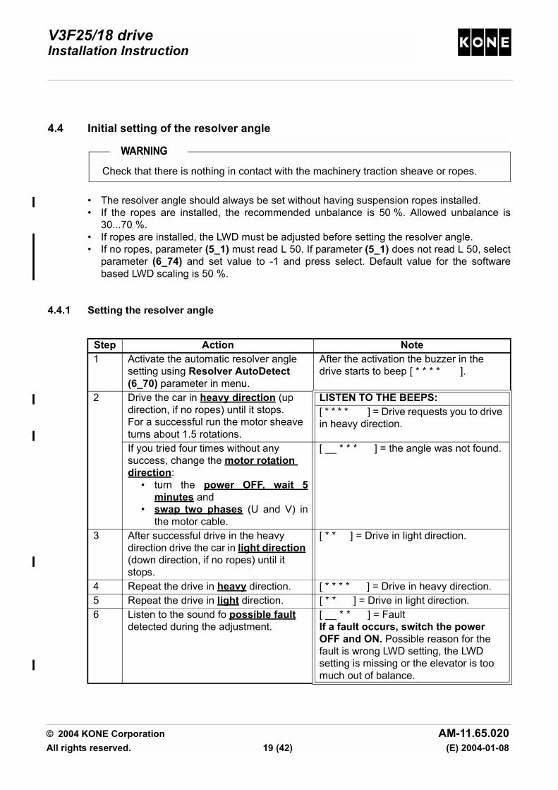
4.4 Initial setting of the resolver angle
• The resolver angle should always be set without having suspension ropes installed.• If the ropes are installed, the recommended unbalance is 50 %. Allowed unbalance is
30...70 %.• If ropes are installed, the LWD must be adjusted before setting the resolver angle.• If no ropes, parameter (5_1) must read L 50. If parameter (5_1) does not read L 50, select
parameter (6_74) and set value to -1 and press select. Default value for the softwarebased LWD scaling is 50 %.
4.4.1 Setting the resolver angle
WARNINGCheck that there is nothing in contact with the machinery traction sheave or ropes.
Step Action Note1 Activate the automatic resolver angle
setting using Resolver AutoDetect (6_70) parameter in menu.
After the activation the buzzer in the drive starts to beep [ * * * * ].
2 Drive the car in heavy direction (up direction, if no ropes) until it stops.For a successful run the motor sheave turns about 1.5 rotations.
LISTEN TO THE BEEPS:[ * * * * ] = Drive requests you to drive in heavy direction.
If you tried four times without any success, change the motor rotation direction:
• turn the power OFF, wait 5minutes and
• swap two phases (U and V) inthe motor cable.
[ __ * * * ] = the angle was not found.
3 After successful drive in the heavy direction drive the car in light direction (down direction, if no ropes) until it stops.
[ * * ] = Drive in light direction.
4 Repeat the drive in heavy direction. [ * * * * ] = Drive in heavy direction.5 Repeat the drive in light direction. [ * * ] = Drive in light direction.6 Listen to the sound fo possible fault
detected during the adjustment. [ __ * * ] = FaultIf a fault occurs, switch the power OFF and ON. Possible reason for the fault is wrong LWD setting, the LWD setting is missing or the elevator is too much out of balance.
© 2004 KONE Corporation AM-11.65.020All rights reserved. 19 (42) (E) 2004-01-08
V3F25/18 driveInstallation Instruction
4.4.2 Checking the resolver angle and recording the value
Step Action Note1 Read the value of Resolver angle
(6_61) parameter.If the value is 0, restart the adjustment.
It is recommended to repeat the adjustment to get a more accurate angle value.
If no other possibility, resolver angle can also be found manually by entering the value of Resolver angle (6_61) parameter in the range of 1 - 360 degrees. Change the value by increments of 20 degrees. Attempt to run the car after each increment. Resolver angle is satisfactory when the car runs. Fine tuning will be required before final commissioning.
2 Select Save (6_99) parameter. 0 is blinking in the display.Turn 0 to 1 and press ACCEPT. 0 turns steady.
3 Check that correct value is recorded.
© 2004 KONE Corporation AM-11.65.020All rights reserved. 20 (42) (E) 2004-01-08

V3F25/18 driveInstallation Instruction
5 COMMISSIONING OF THE MACHINE AFTER ROPING
Refer to the elevator level installation manual before commissioning with ropes.
5.1 LWD setup
Normal drive including relevelling are not permitted until LWD setup is done. RDF (machineroom inspection drive in North America) and setup drive are permitted.
5.1.1 Checking the LWD operation
MiniSpace™, MonoSpace® Special and elevators in North America (EcoSystem MR®and MonoSpace®):
MonoSpace® and TranSys™ elevators with V3F18 drive:Do this check only if there are problems.
Step Action Note1 Turn the elevator to RDF (machine room inspection drive in North America).2 Ensure that the car is empty. Drive the car to suitable floor level.3 Check the mechanical adjustment of LWD under the car.4 Check that voltage between points LWD - AGND on HCB board is between 0.5 V
and 1.5 V. If not, check the air gap. It should be 3 - 5 mm.
Step Action Note1 Turn the elevator to RDF.2 Ensure that the car is empty. Drive the car to suitable floor level.3 Add and remove some load in car and see that the voltage between points LWD
and AGND on the HCB board is changing when changing the load in car. If the voltage does not change, check connections and mechanical condition of LWD. You may have to replace LWD and its hanger.
© 2004 KONE Corporation AM-11.65.020All rights reserved. 21 (42) (E) 2004-01-08

V3F25/18 driveInstallation Instruction
5.1.2 Basic LWD setting
Follow this working order exactly. If you forget one step or give wrong values, you have torestart whole LWD setting.
Step Action On displayReset the LWD setup.1 Select Enable LWD setup (6_74)
parameter.0 is blinking.
Turn 0 to -1 (minus one). -1 is blinking.Push ACCEPT. 6_74_0, all digits start to blink.Push MENU. 6_74
2 Select Save (6_99) parameter . 0 is blinking.Turn 0 to 1 and push ACCEPT. 0 turns steady.
Zero load:3 Select Enable LWD setup (6_74)
parameter.0 is blinking.
Push ACCEPT. 6_74_0, all digits start to blink.Push MENU. 6_74
Half load:4 Place from 40 % to 60 % of the rated
load in the car. 6_74
Push ACCEPT. 0 is blinking.Give the load value in kilos (kg). Load value is blinking.Push ACCEPT. 6_74_0, all digits start to blink.Push MENU 6_74
5 Select Save (6_99) parameter . 0 is blinking in the display.Turn 0 to 1 and press ACCEPT. 0 turns steady.
6 Leave menu 6 and check that the correct value is recorded by reading the value of LWD adjustment (5_1) parameter.
7 Check that the LWD information changes when the load is changing.
© 2004 KONE Corporation AM-11.65.020All rights reserved. 22 (42) (E) 2004-01-08

V3F25/18 driveInstallation Instruction
5.1.3 Fine tuning the LWD setting
Follow this working order exactly. If you forget one step or give wrong values, you have torestart whole LWD setting.
Fine adjustment of LWD with full load setting is necessary only if there are difficulties to getaccurate LWD values when the car is full loaded.
Step Action On displayFull load: 1 Place more than 90 % of the rated load in the car.
In MiniSpace™ and MonoSpace® Special elevators: Check that the springs under the car are not fully compressed. Select Enable LWD setup (6_74) parameter.
0 is blinking.
Give the load value in kilos (kg). Load value is blinking.Push ACCEPT. 6_74_0, all digits start to blink.Push MENU 6_74
2 Select Save (6_99) parameter . 0 is blinking in the display.Turn 0 to 1 and press ACCEPT. 0 turns steady.
3 Leave menu 6 and check that the correct value is recorded by reading the value of LWD adjustment (5_1) parameter.
LWD
inpu
t vol
tage
(V)
A = Slope defined using 2 reference points.B = Slope defined using 3 reference points.0 = Zero load.2. = Half load (40 - 60 %).3. = Full load (> 90 %)
Load in car (kg)
1008860.wmf
V
kg
AB
40 - 60% >90%
0
2.3.
© 2004 KONE Corporation AM-11.65.020All rights reserved. 23 (42) (E) 2004-01-08

V3F25/18 driveInstallation Instruction
5.2 Repeating the resolver angle setting
Repeat the resolver angle setting when the ropes are installed.
This must be done before shaft setup.
Refer to Initial setting of the resolver angle.
5.3 Shaft setup
Step Action Note1 Ensure that the elevator is in RDF mode (machine room inspection drive mode in
North America).2 Drive the car just below the bottom floor.3 Check that the LEDs 61:U, 77:N and
77:S light.LED 61:N must not light. LCE LEDs 30 and/or B30 must light.
4 Activate the setup mode from the controller.Set Shaft setup (5_2) parameter to 1.
The buzzer on the HCB board starts to sound: long beeps with some delay. [ ___ ]
5 Turn the RDF (machine room inspection drive in North America) to normal.
Elevator starts the setup drive upwards.
6 Follow the setup drive steps on the user interface.
Elevator is ready for the normal drive when the elevator stops at the topmost floor and the user interface shows the number of the topmost floor.
© 2004 KONE Corporation AM-11.65.020All rights reserved. 24 (42) (E) 2004-01-08
V3F25/18 driveInstallation Instruction
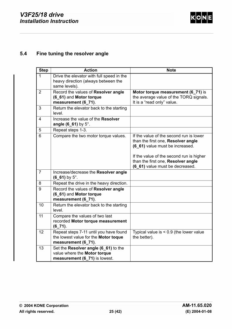
5.4 Fine tuning the resolver angle
Step Action Note1 Drive the elevator with full speed in the
heavy direction (always between the same levels).
2 Record the values of Resolver angle (6_61) and Motor torque measurement (6_71).
Motor torque measurement (6_71) is the average value of the TORQ signals. It is a “read only” value.
3 Return the elevator back to the starting level.
4 Increase the value of the Resolver angle (6_61) by 5°.
5 Repeat steps 1-3.6 Compare the two motor torque values. If the value of the second run is lower
than the first one, Resolver angle (6_61) value must be increased.
If the value of the second run is higher than the first one, Resolver angle (6_61) value must be decreased.
7 Increase/decrease the Resolver angle (6_61) by 5°.
8 Repeat the drive in the heavy direction.9 Record the values of Resolver angle
(6_61) and Motor torque measurement (6_71).
10 Return the elevator back to the starting level.
11 Compare the values of two last recorded Motor torque measurement (6_71).
12 Repeat steps 7-11 until you have found the lowest value for the Motor toque measurement (6_71).
Typical value is < 0.9 (the lower value the better).
13 Set the Resolver angle (6_61) to the value where the Motor torque measurement (6_71) is lowest.
© 2004 KONE Corporation AM-11.65.020All rights reserved. 25 (42) (E) 2004-01-08

V3F25/18 driveInstallation Instruction
6 FINE ADJUSTMENTS
It is necessary to fine adjust the setting combinations to optimise the ride comfort.
Before the fine adjustments ensure that the installation is completed and elevator is correctlybalanced:
• 50 % of the rated load in the car.• Car located in the mid of the elevator shaft.• Car and counterweight balance deviation tolerance is ± 50 kg (checked in the elevator
shaft by opening the brake).
Refer to the elevator level installation instruction for the prerequisites before the fineadjustment.
If the elevator mechanics or balancing are changed, the fine adjustment should be repeated.
These adjustments can be done after several successful drives over the full length of travel.
6.1 Drive adjustments and checks (speed control)
Action Too highparameter value
Too lowparameter value
Change the value of P factor (6_20) parameter in 0.5 increments.NOTE!Usually it is better to set the
value as high as possible.
Vibrations and noise in motor.
Car does not reach the floor level.Car may jump during relevelling.Relevelling problems.
Change the value of I factor (6_26) parameter in 0.5 increments.
Car does not reach the floor.May decrease vibrations.
May cause noise in motor.May cause other vibrations.
Change the value of Tacho filter time (6_36) parameter step by step.NOTE!This parameter is typically
changed to avoid interference in tachometer signal.
Car may not reach the floor.May cause overspeeding.
Change the value of KTW/Q (6_29) parameter.KTW/Q = total moving masses divided by elevator load. Moving masses = sling + car + car door + decoration + counterweight + ropes + travelling cable + compensation (if applicable).
It is better to set this a little bit higher than the calculated value.
Car does not reach the floor.Car movement does not follow the speed curve.Car jumps when landing a floor.Relevelling problems.
© 2004 KONE Corporation AM-11.65.020All rights reserved. 26 (42) (E) 2004-01-08

V3F25/18 driveInstallation Instruction
6.2 Starting
6.3 Jerky start or roll back
Whenever the resolver angle is changed or fine tuned, repeat these adjustments.Repeat these adjustments always before leaving the elevator in normal use. Shaft setup should be done before these adjustments. It is important to adjust these infollowing order.
6.3.1 Preparations
Step Action Note1 If the mechanical brakes are still
engaged when the drive starts, increase the value of Start delay (6_37) parameter.Recheck the operation.
Normally the brake start delay parameter does not need adjustment.NOTE!Do not increase the value
unnecessarily. A too high value decreases the performance of the elevator.
Step Action Note1 Check the load weighing information.
Adjust if needed.See LWD setup.
2 Set the value of Start delay (6_37) parameter to 1 second.
These are temporary settings for the next adjustments.
3 If the value of P factor (6_20) parameter is more than 1.5 set the value to 1.5.
© 2004 KONE Corporation AM-11.65.020All rights reserved. 27 (42) (E) 2004-01-08

V3F25/18 driveInstallation Instruction
6.3.2 Balancing error parameter
Load corresponding 50 % of the rated load must be in the car. The car must be in themiddle of the elevator shaft.
6.3.3 Rope weight parameter
Load corresponding 50 % of the rated load must be in the car. The car must be at thebottom floor.
Step Action Note1 Observe the movement of the elevator
during the start.Drive the elevator up and down a few times in RDF mode (machine room inspection drive mode in North America) from the middle of the elevator shaft.Adjust the value of Balancing error (6_28) parameter in 0.02 increments until the starts get better and are similar in both directions.
Default value of Balancing error (6_28) parameter is 0.NOTE!Parameter can also have
negative values.
Always start to drive from the same level.Wait 10 sec. between successive drives: the LWD signal oscillates for a while after stopping.
2 Choose the correct value according to the best starting (= similar starting to up and down) reached.
If the value is too high, the motor tends to rotate downwards while starting.If the value is too low the motor tends to rotate upwards while starting.
Step Action Note1 Drive the elevator upwards a few times
in RDF mode (machine room inspection drive mode in North America) from the bottom floor.Observe the movement of elevator during the start.
Rope weight (6_30) parameter:No compensating ropes => value 3.0.Compensating ropes => value 0.Overcompensation causes negative value.
Always start to drive from the bottom floor.Wait 10 sec. between successive drives: the LWD signal may oscillate for a while after stopping.
If there is roll back, decrease the value of Rope weight (6_30) parameter in 0.5 increments.If there is jerk (small uncontrolled acceleration), increase the value of Rope weight (6_30) parameter in 0.5 increments.
2 Choose the correct value according to the best starting (= no uncontrolled acceleration) reached.
© 2004 KONE Corporation AM-11.65.020All rights reserved. 28 (42) (E) 2004-01-08

V3F25/18 driveInstallation Instruction
6.3.4 Start torque scaling parameter
Empty car must be at the bottom floor.
6.3.5 Setting start delay and P factor parameters to original values
6.4 Stopping (final rounding to the floor)
Step Action Note1 Drive the elevator upwards a few times
in RDF mode (machine room inspection drive mode in North America) from the bottom floor.Observe the movement of elevator during the start.
Default value of Start torque scaling (6_27) parameter is 1.00.
Always start to drive from the bottom floor.Wait 10 sec. between successive drives: the LWD signal may oscillate for a while after stopping.
If there is roll back, decrease the value of Start torque scaling (6_27) parameter in 0.05 increments.
Step Action Note1 Set Start delay (6_37) and P factor
(6_20) parameters to original values.Refer to the APPENDIX parameter list 779980.
2 Select Save (6_99) parameter. 0 is blinking in the display.Turn 0 to 1 and press ACCEPT. 0 turns steady.
3 Check that the correct value is recorded.
Step Action Note1 For smoother and longer rounding
increase the value of Final jerk distance (6_32) parameter.
If you want faster landing to the floor level decrease the value.
Default value of Final jerk distance (6_32) parameter is 125 mm.Typical cases:
• If ADO is used, set long rounding(125-200 mm).
• If no ADO, set short rounding (25-100 mm).
© 2004 KONE Corporation AM-11.65.020All rights reserved. 29 (42) (E) 2004-01-08
V3F25/18 driveInstallation Instruction
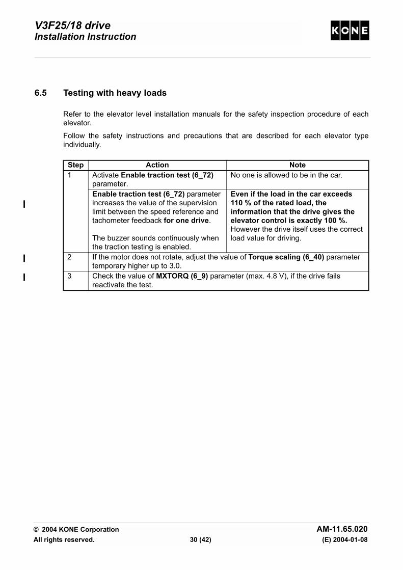
6.5 Testing with heavy loads
Refer to the elevator level installation manuals for the safety inspection procedure of eachelevator.
Follow the safety instructions and precautions that are described for each elevator typeindividually.
Step Action Note1 Activate Enable traction test (6_72)
parameter.No one is allowed to be in the car.
Enable traction test (6_72) parameter increases the value of the supervision limit between the speed reference and tachometer feedback for one drive.
The buzzer sounds continuously when the traction testing is enabled.
Even if the load in the car exceeds 110 % of the rated load, the information that the drive gives the elevator control is exactly 100 %. However the drive itself uses the correct load value for driving.
2 If the motor does not rotate, adjust the value of Torque scaling (6_40) parameter temporary higher up to 3.0.
3 Check the value of MXTORQ (6_9) parameter (max. 4.8 V), if the drive fails reactivate the test.
© 2004 KONE Corporation AM-11.65.020All rights reserved. 30 (42) (E) 2004-01-08

V3F25/18 driveInstallation Instruction
6.6 Balance measurement in elevators with V3F18 drive and MAP panel
Step Action Note1 Measure the voltage in the
maintenance panel between test pins TP1 and TP2 on LOP-CB board in MAP panel. This voltage is equivalent to the motor current.
Scaling ratio of the measurement: 38 mV corresponds 1 A.
Measuring points on LOP-CB board:
2 Drive the empty car downwards and with rated load upwards.
Use rated speed. Measure these values at same level in the elevator shaft.
3 Record values. The difference of the measurements may be about 5 %.
4 If the difference is more than 5 %, recheck the elevator mechanical balancing.Check also the adjustment of guide shoes or rollers against the guide.
Measured voltage
Motor current
Figure
1.1 VDC 29 A1.2 VDC 32 A1.3 VDC 34 A1.4 VDC 37 A1.5 VDC 39 A1.6 VDC 42 A1.7 VDC 45 A1.8 VDC 47 A1.9 VDC 50 A2.0 VDC 53 A2.1 VDC 55 A1.1 VDC 29 A
TP1TP2
1019849.wmf
10 20 30 40 50 A0
0.5
1.0
1.5
2.0
V
1008915.wmf
© 2004 KONE Corporation AM-11.65.020All rights reserved. 31 (42) (E) 2004-01-08

V3F25/18 driveInstallation Instruction
6.7 Balance measurement in elevators with V3F25 drive
Step Action Note1 Measure the voltage between MEAS
test point and AGND on HCB board. This voltage is equivalent to the motor current.
Measuring points on HCB board:
2 Drive the empty car downwards and with rated load upwards.
Use rated speed. Measure these values at same level in the elevator shaft.
3 Record values. The difference of the measurements may be about 5 %.
4 If the difference is more than 5 %, recheck the elevator mechanical balancing.Check also the adjustment of guide shoes or rollers against the guide.
V3F25 drive, nominal current
CMB boardPass through
MEAS test point1 VAC equals
40 A, 782999G01 2 30 A80 A, 782999G02 1 60 A100 A, 782999G04 1 80 A
M3R525
R526
XI1
MEAS
NEG10V
AGND2 AGND
XW1
XLG
1
CURRENT
MAP INTERFACE
TACHOR
TRR
TS
TXD V81
V79RXDV45PICKUP
XT1
XN1
MOTOR
NTS INTERFACE
TEMPERATURE
F2
LWD
XWLOADWEIGHING
1019851.wmf
© 2004 KONE Corporation AM-11.65.020All rights reserved. 32 (42) (E) 2004-01-08
V3F25/18 driveInstallation Instruction
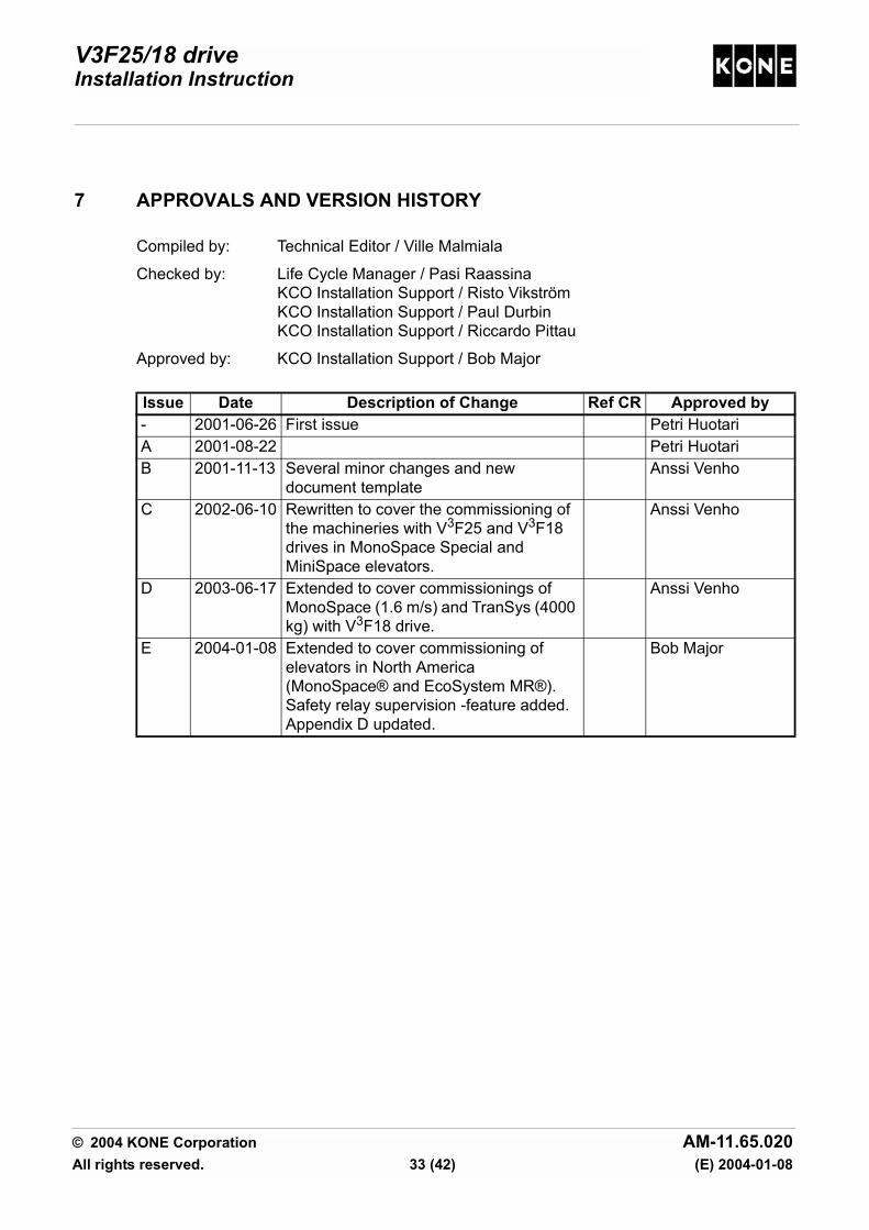
7 APPROVALS AND VERSION HISTORY
Compiled by: Technical Editor / Ville Malmiala
Checked by: Life Cycle Manager / Pasi Raassina KCO Installation Support / Risto Vikström KCO Installation Support / Paul Durbin KCO Installation Support / Riccardo Pittau
Approved by: KCO Installation Support / Bob Major
Issue Date Description of Change Ref CR Approved by- 2001-06-26 First issue Petri HuotariA 2001-08-22 Petri HuotariB 2001-11-13 Several minor changes and new
document templateAnssi Venho
C 2002-06-10 Rewritten to cover the commissioning of the machineries with V3F25 and V3F18 drives in MonoSpace Special and MiniSpace elevators.
Anssi Venho
D 2003-06-17 Extended to cover commissionings of MonoSpace (1.6 m/s) and TranSys (4000 kg) with V3F18 drive.
Anssi Venho
E 2004-01-08 Extended to cover commissioning of elevators in North America (MonoSpace® and EcoSystem MR®).Safety relay supervision -feature added.Appendix D updated.
Bob Major
© 2004 KONE Corporation AM-11.65.020All rights reserved. 33 (42) (E) 2004-01-08
V3F25/18 driveInstallation Instruction
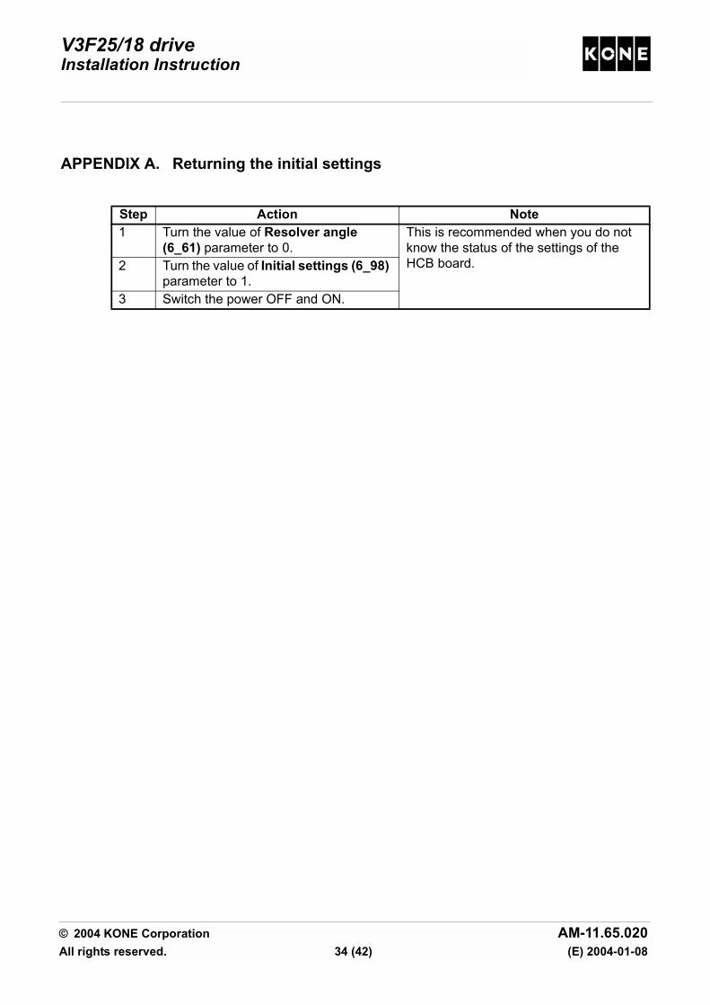
APPENDIX A. Returning the initial settings
Step Action Note1 Turn the value of Resolver angle
(6_61) parameter to 0.This is recommended when you do not know the status of the settings of the HCB board.2 Turn the value of Initial settings (6_98)
parameter to 1.3 Switch the power OFF and ON.
© 2004 KONE Corporation AM-11.65.020All rights reserved. 34 (42) (E) 2004-01-08

V3F25/18 driveInstallation Instruction
APPENDIX B. Buzzer warnings
• [ * ]: a short beep• [ __ ]: a long beep• [ q ]: 15 sec. delay• [ m ]: 1 min. delay• [ ]: approx. 1 sec. delay• [ _______ ]: continuous beep
Warning Buzzer code1 Module too hot or cold. [ __ * __ * m ]2 Motor hot. [ __ * m ]3 Resolver angle is not adjusted, angle value is zero. [ * * * * q]4 Resolver Autodetect (6_70) function is activated
- driving to heavy direction (up).[ * * * * ]
5 Resolver Autodetect (6_70) function: driving to light direction (down).
[ * * ]
6 Resolver Autodetect (6_70) function: There is a fault in adjustment procedure.
[ __ * * ]
7 Resolver Autodetect (6_70) function: Angle value could not be found.Refer to Initial setting of the resolver angle.
[ __ * * * ]
8 Setup is not done. [ * __ * m ]9 Setup command is active. [ __ ]10 Setup: Fault in the elevator shaft devices during the setup. [ __ * * * * q ]11 NTS error: V3F has started NTS deceleration in
normal mode.[ * * * q ]
12 Parameter value is changed. [ * q ]13 Position fault in V3F. [ * __ ]14 Buffer and traction tests. [ _______ ]
© 2004 KONE Corporation AM-11.65.020All rights reserved. 35 (42) (E) 2004-01-08

V3F25/18 driveInstallation Instruction
APPENDIX C. Troubleshooting
C.1 Connections
If the motor does not rotate check that the connections are correct. Refer to the circuitdiagrams and maintenance instruction AS-11.65.020.
C.2 Drive fault codes
Check the connection of connectors XSR1 (safety relay input) and XM1 (MLB Interface) on HCB board.Refer to the circuit diagrams.
If you have to change the connection of the connector XSR1 (safety relay input) or XM1 (main contactor supervision), switch the power off.The new connection will be valid after power up.
One example of the connections:Safety relay connection is not used.Main contactor (A) is supervised.XSR1 is overconnected. Set the value of parameter (6_38) to 0, 1, 2, or 3.
Fault Symptoms of fault ActionDrive faults0101 Drive stop
Emergency stop or Error detected by the drive diagnostics.
See other fault codes.
0102 Motor overcurrent.
Emergency stop.Prevents new drive before the fault is corrected.
• Check the drive parameters. • Check the current scaling.• Check the mechanical brake.
0103 Damaged Braking resistor or electrical circuits.
Emergency stop • Check the circuits of thebraking resistors.
• Check condition andconnection of the brakingresistors.
X3
F1
XB1
POS12V
XM1
NEG12V
XSR1
POWER
SIN-DATA
SAFETY RELAY
MLB INTERFACE
LBE
BRAKEPO
WER
MC
SU
PLB
R
1019852.wmfA
1 6
© 2004 KONE Corporation AM-11.65.020All rights reserved. 36 (42) (E) 2004-01-08

V3F25/18 driveInstallation Instruction
0104 Motor too hot
Prevents new drive before the fault is corrected.
• Check the machine roomventilation
• Check the resolver angle(measure the current)
• Check resistance of thethermistor circuit
0105 AC voltage in the intermediate circuit is too low or too high.
Emergency stop. Prevents new drive before the fault is corrected.
• If the supply voltage dropsduring drive, decrease theacceleration rate atacceleration (6_21)parameter.
• If this fault is active duringstart, check the chargingcircuit, fuses and brakingtransistor.
0106 Inverter not OK
Prevents new drive before the fault is corrected.
• Check connections oftachometer and thermal switch(XM2).
• The value for Tacho faultcounter (6_35) parameter maybe too sensitive. Turn theelevator to RDF (machineroom inspection in NorthAmerica) and back to Normalto reset the tacho fault counter.
• If LBR LED does not light, referto AS-11.65.008 and circuitdiagrams.
• If LBR lights but LBE is notactivated at start, check(6_38).
• If MLB is 'shutdown', checkvoltage in the supply and X10/16 in MLB (+24V).
• Remove the UREF2 jumper.0107 LWD adjustment value out of scale.
Elevator controller prevents the drive. (Drive allows driving)
• Check the LWD mechanicaladjustment and settings of theload values.
• Check the load in car.
Fault Symptoms of fault Action
© 2004 KONE Corporation AM-11.65.020All rights reserved. 37 (42) (E) 2004-01-08

V3F25/18 driveInstallation Instruction
0108 Motor /Tacho failure
Emergency stop Elevator overspeeds or does not follow the speed reference.
• Check the condition and wiringof the tachometer
• Check mechanical brakes• Check the connections for
loose contacts.• Check earthings.• Check the initial drive settings/
adjustments0109 Position lost
Elevator does not take car calls, but drives correction and synchronisation drives.
• Check the 61 vanes, 77 andNTS switches.
• Check the actual speed, tachoscaling and parameters.
• Perform the shaft setup aftervane /switch adjustment.
0110 Drive temperature too high / low
Car is stopped at landing. The temperature at heat sink is too low or high or locked current function operates. (Elevator starts 5 minutes after the heat sink is cooled two degrees under the limit).
• Check ventilation of themachine room and operation ofthe cooling fan.
• Check connections of thetemperature sensor on CMBboard.
• Check that the mechanicalbrake opens correctly whenthe elevator starts.
• Check the adjustments toprevent unnecessary re-levelling.
Faults related to shaft setup0111 Vane 61:N below 61:U
Shaft setup not completed. • Check the order of switches61:U and N.
• Check that the vanes ormagnets are positionedaccording to the shaft vanediagram.
• Perform the shaft setup aftervane or magnet/switchadjustment.
Fault Symptoms of fault Action
© 2004 KONE Corporation AM-11.65.020All rights reserved. 38 (42) (E) 2004-01-08

V3F25/18 driveInstallation Instruction
0112 Overlapping of switches 61:U and N too small
Shaft setup not completed. • Check that the vanes ormagnets and switches arepositioned according to theshaft vane diagram.
• If there are vanes they must becorrectly aligned in accordanceto the oscillator reader.
• Perform the shaft setup aftervane or magnet/switchadjustment.
0113 Synchronisation switch fault
Shaft setup not completed. • Check the positioning of themagnets and the gap betweenswitch and magnet.
• Perform the shaft setup aftervane /switch adjustment.
0114 Too short distance between the floors.
Shaft setup not completed. • Check that the vanes andswitches are positionedaccording to the shaft vanediagram.
• Perform the shaft setup aftervane /switch adjustment.
0115 Overlapping of switches 61:U and N too long in the topmost floor.
Shaft setup not completed. • Correct the positioning of thevanes.
• Perform the shaft setup aftervane /switch adjustment.
0116 Wrong top floor count
Shaft setup not completed. • Perform the shaft setup.
Fault Symptoms of fault Action
30 - 35 mm
==
1018076.wmf
© 2004 KONE Corporation AM-11.65.020All rights reserved. 39 (42) (E) 2004-01-08

V3F25/18 driveInstallation Instruction
0117 Shaft setup not done
Elevator does not run the normal drive. Only RDF (machine room inspection drive in North America) and inspection drives are possible.
• Perform the shaft setup.
Other faults0125 Torque limit exceeded
MXTORQ (6_9) parameter shows on display -, -- or emergency stop during acceleration.
• Check the parameters forMXTORQ.
• Check the motor cableconnections.
• Increase the value of Torquescaling (6_40) parameter.
0126 Safety relay open
Emergency stop.Elevator does not start.
• Check the connection of XSR1on HCB board and controlpanel.
• Check parameter (6_38).0127 Main contactor not energized
Emergency stop /Main contactor time out (2 seconds).
Check the circuits of the main contactor (MC_SUP LED).
0128 LWD setup not done
Normal drive prevented. Load values for Enable LWD setup (6_74) parameter are not set.
Perform the LWD setup. (Minimum two values must be given)
NTS faults0150 V1 NTS switch faulty
Elevator stops, correction drive and returns to the bottom floor.
Check the order and operation of NTS switches.
0151 V1 NTS switch fault
Elevator stops, correction drive and returns to the bottom floor.
Check the positioning and operation of NTS switches.
0152 V1 NTS stopping
Position lost and the elevator stopped by the NTS switches.
See fault 0109 “Position lost”.
Fault Symptoms of fault Action
© 2004 KONE Corporation AM-11.65.020All rights reserved. 40 (42) (E) 2004-01-08

V3F25/18 driveInstallation Instruction
APPENDIX D. Parameter table 779980 V3F18/V3F25M Parameter Table
The document id of this sheet must
match with the id reported by LCE
menu 6_0.
This menu can be
used only when the
drive is in the
inspection mode !!LCE
menu unit range
Initial
value
Drive
settings
- document identification of the parameter set (= this sheet) 6_0 2011 20116_1 10, 18, 20, 32 18
6_2 m/s 0,5, ..., 3,5 2,5
6_3 kg 400, ..., 7 000 630
- roping (roping system that reduce car speed by 1x, 2x or 4x) 6_4 1, 2, 4 2
6_5 1, 2 2
6_6 Nm/A 5,0, ..., 150,0 29,7
- traction sheave diameter (determines resolver scaling) 6_7 mm 480, ..., 750 650
6_8 mm 37,50, 55,00, 75,00 75,00
Calculated values: NOTE! MXTORQ and TAC are read only values !
6_9 V 0,000, ..., 5,000 2,344
6_10 V -2,350, ..., -7,450 -3,572
6_20 s/m 0,0, ..., 15,9 5,0
6_21 m/s20,3, ..., 1,2 0,8
- inspection speed (= elevator speed in inspection or RDF mode) 6_22 m/s 0,3, 0,5 0.3
6_23 0,15, ..., 1,00 0,50
6_24 m/s 0,01, ..., 0,05 0,03
- ADO speed (speed level supervision for ADO and relevelling operation) 6_25 m/s 0,20, ..., 0,70 0,50
6_26 sec 0,05, ..., 1,00 0,20
6_27 0,50, ..., 1,10 1,00
6_28 -0,30, ..., 0,30 0,00
- KTW/Q factor (= total moving masses / elevator load) 6_29 0,4, ..., 7,0 2,8
6_30 kg/m -2,0, ..., 7,0 0,0
6_31 kg/m 0,00, ..., 5,00 0,00
- final jerk distance (= additional distance used for final jerk) 6_32 mm 0, ..., 250 125
6_33 mm 0, ..., 20 0
6_34 0,400, ..., 0,900 0,900
- tacho fault counter (0=off, nn=tacho fault counter limit to stuck the drive) 6_35 0, ..., 10 0
6_36 ms 0, ..., 40 0
6_37 s 0,01, ..., 1,00 0,25
6_38 0, ..., 13 10
6_39 1, 2 1
6_40 1,66, ..., 3,33 2,50
6_41 A/V 40, ..., 80 60,0
6_42 mm 50, ..., 500 150
6_60 10, 12, 19 12
6_61 ° ele 0, ..., 360 0
Commissioning and tests NOTE! Traction and buffer tests are valid for one start only. - Resolver AutoDetect (resolver angle automatic tuning) 6_70 0, 1 0
6_71 -1,500, ..., 1,500 0
6_72 0, 1 0
6_73 0, 1 0
- enable LWD setup (-1 = clear setup, 0 = empty car, nnn = load in kg) 6_74 kg -1, 7 000 0
Permanent Store NOTE! Set resolver angle (6_61) to 0 before downloading initial settings (6_98).
Whenever initial settings are downloaded, make power break ! - initial settings 6_98 0, 1 0
- save (saves parameters into permanent memory) 6_99 0, 1 0
Copyright (C) 1999 KONE Corporation. All rights reserved.
- tacho pulley diameter (37.5mm, 55 mm or 75.mm)
- MXTORQ (maximum torque voltage)
- TAC (tacho test voltage)
Elevator depedendent values
- elevator load (car nominal load in kilos)
- current sensor scaling (= 40A module wire 2 times thru, 80A
module wire 1 time thru)
- Ktc factor (torque vs current from the motor label)
- Motor type (MX10,MX18, MX20, MX32)
- nominal speed (of the elevator)
- start torque scaling
- balancing error
- rope weight
Additional parameters:
- P factor (= proportional gain of speed controller)
- acceleration (determines also jerk)
- speed reduction (= reduced speed / nom. speed)
- Resolver type (1=1x resolver, 2=2x resolver)
- torque scaling (=max torque / nominal torque)
- enable line bridge / safety relay supervision (exists)
yes no
not used 10 0
except half speed or correction drive 11 1
except correction drive 12 2
used all the time 13 3
- enable buffer test
- CM scaling (= current measurement scaling: 100A module uses
80A/V, others 60A/V.)
- vane length (= mechanical length of 61 vanes)
Machinery Parameters:
- number of pole pairs
- enable traction test
779980.XLS
- resolver angle
- motor torque measurement
- car cable weight
- relevelling correction distance
- relevelling speed
- tacho scaling factor
- tacho filter time
- I factor (= integration time of speed controller)
- start delay (= brake open command -> speed ref.)
© 2004 KONE Corporation AM-11.65.020All rights reserved. 41 (42) (E) 2004-01-08

V3F25/18 driveInstallation Instruction
© 2004 KONE Corporation AM-11.65.020All rights reserved. 42 (42) (E) 2004-01-08
This page has been added to make double-sided printing easier.