commercialization of military & space electronics - conference · commercialization of military...
TRANSCRIPT

Commercialization of Military & Space Electronics - Conference
Commercial Off-The-Shelf (COTS) ProgramUsing Nondestructive Methods (C-SAM) for COTS
PEMs Screening and Qualification
Mike Sandor, Shri Agarwal 4800 Oak Grove Drive Pasadena, CA 91109
Phone: (818) 354-0681 FAX: (818) 393-4559JPL 1
JET PROPULSION LABORATORYElectronic Parts Engineering Office
AGENDA:C-SAM Inspection
Failure Mechanisms/Studies
C-SAM Screening Method
Test Data
Reject Criteria/Failure Analysis
Other Work
Summary
The work was performed at Jet Propulsion Laboratory California Institute of Technology under contract to the National Aeronautics and Space Administration
2JPL
JET PROPULSION LABORATORYElectronic Parts Engineering Office
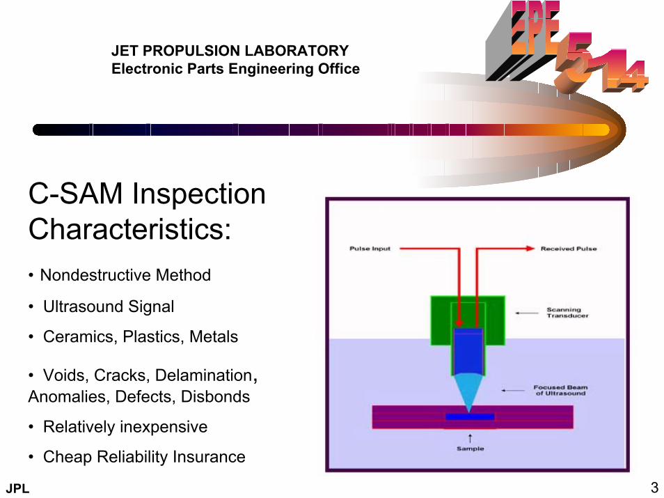
C-SAM Inspection Characteristics:• Nondestructive Method
• Ultrasound Signal
• Ceramics, Plastics, Metals
• Voids, Cracks, Delamination, Anomalies, Defects, Disbonds
• Relatively inexpensive
• Cheap Reliability Insurance
3JPL

JET PROPULSION LABORATORYElectronic Parts Engineering Office
Possible Failure Mechanisms from PEM Delamination Based on Independent Studies:
• Stress-induced passivation damage over the die surface
• Wire bond degradation due to shear displacement
• Accelerated metal corrosion
• Die attach adhesion
• Intermittent electricals at high temperature
• Popcorn cracking
• Die cracking
• Device Latch Up
4JPL

JET PROPULSION LABORATORYElectronic Parts Engineering Office
Eight Independent Studies on C-SAM Delamination /Reliability:• Failure Criteria for Inspection Using Acoustic Microscopy After Moisture Sensitivity Testing of Plastic Surface Mount Devices; Alcatel Bell, Texas Instruments, Philips Semiconductor
• A Case Study of Plastic Part Delamination; ITT Aerospace/Communications
• The Application of Scanning Acoustic Microscopy to Control Moisture/Thermal Induced Package Defects; Texas Instruments
• C-SAM Analysis of Plastic Packages to Resolve Bonding Failure Mode Miscorrelations; Texas Instruments
• On the Role of Adhesion in Plastic Packaged Chips Under Thermal Cycling Stress; Siemens
• Relation Between Delamination and Temperature Cycling Induced Failures in Plastic Packaged Devices
• Correlation of Surface Mount Plastic Package Reliability Testing to Nondestructive Inspection by Scanning Acoustic Microscopy; Texas Instruments
• The Mystery of the Cracked Dice; Analog Devices
5JPL

C-SAM Inspection Points for delamination which can accelerate entry of moisture/collection
Popcorning Failure Mechanism from Internal Moisture
6JPL

JET PROPULSION LABORATORYElectronic Parts Engineering Office
C-SAM Finds Hidden Defects
Die-attach material serves three functions: attach die to die substrate, conducts heat away from die, and absorbs some internal stresses.
SILICON DIE
SUBSTRATE(die paddle)
Void at Die interface expanding as delamination
Crack in die-attach material
Delamination growing along substrate
Delamination growing along die
Isolated void (bubble or from outgassing)
Lack of die attach material between die and substrate
HIDDEN DEFECTS IN IC PACKAGES (PLASTIC) CAN AFFECT RELIABILITY
17JPL

DPA ELECTRICAL X-Ray
ELECTRICAL
TEMP CYCLE
Burn-in ELECTRICAL
ASSEMBLE HARDWARE
IDENTIFY & REVIEW REQUIREMENTS
ASSEMBLY TEST
ASSEMBLY QUALIFICATION
FLIGHT READY
COST & TAILOR OBJECTIVES
C-SAM
JET PROPULSION LABORATORYElectronic Parts Engineering Office
C-SAM is Included in JPL’s Full Part Level Screening
COTS++ Plastic Infusion Critical Screening Flow (Tailored for Project application/mission requirements)
7JPL

JET PROPULSION LABORATORYElectronic Parts Engineering Office
COTS++ Upscreening Rejects by Part Type & Vendor Amplifier- A ADC- B ADC2-B DC-DC Con.-C Voltage C-A S.Regulator-B
0/4 1/8 TBD 0/4 0/4 0/4
0/78 n/a 4/79 1/78 0/80 8/80
3/78 38/78 9/75 16/77 5/80 0/80
0/78 10/78 0/75 3/77 0/80 3/72
0/78 3/68 0/75 0/74 0/80 9/69
0/10 0/10 0/10 0/10 0/10 0/10
3/78 51/78 TBD 20/78 5/80 20/80
DPA:
Incoming:
C-SAM:
Temp Cycle:
Burn-In:
QCI:
Total:
8JPL

JET PROPULSION LABORATORYElectronic Parts Engineering Office
LOT by LOT Test Results:
Results are
package/ vendor
assembly dependent.
Failed lots were replaced and retested.
Lot sizes range
from 15-30 parts each.
CSAM Yields06/12/2000
Part Type Manufacturer Yield
NPN Transistor 1 A 83%Switching Diode A 0%NPN Transistor 2 A 100%Zener Diode A 50%NPN Transistor 3 A 100%Op-Amp 1 B 87%Op-Amp 2 C 0%Op-Amp 3 C 7%Phase Detector D 100%MMIC E 40%
9JPL
JET PROPULSION LABORATORYElectronic Parts Engineering Office
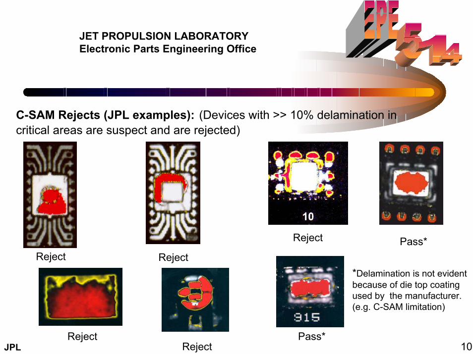
C-SAM Rejects (JPL examples): (Devices with >> 10% delamination in critical areas are suspect and are rejected)
Reject Pass*Reject Reject
*Delamination is not evident because of die top coating used by the manufacturer. (e.g. C-SAM limitation)
Reject Pass*Reject 10JPL

JET PROPULSION LABORATORYElectronic Parts Engineering Office
C-SAM Delaminations Confirmed by Failure Analysis: (JPL examples):
C. Delamination and lack of adhesion between
die and heat sink
A. Die attach void at
the heat sink surface
B. Bubble exists from
Mylar tape near pin 5
Definitive results were found on six suspect problem areas submitted for analysis.
11JPL
JET PROPULSION LABORATORYElectronic Parts Engineering Office
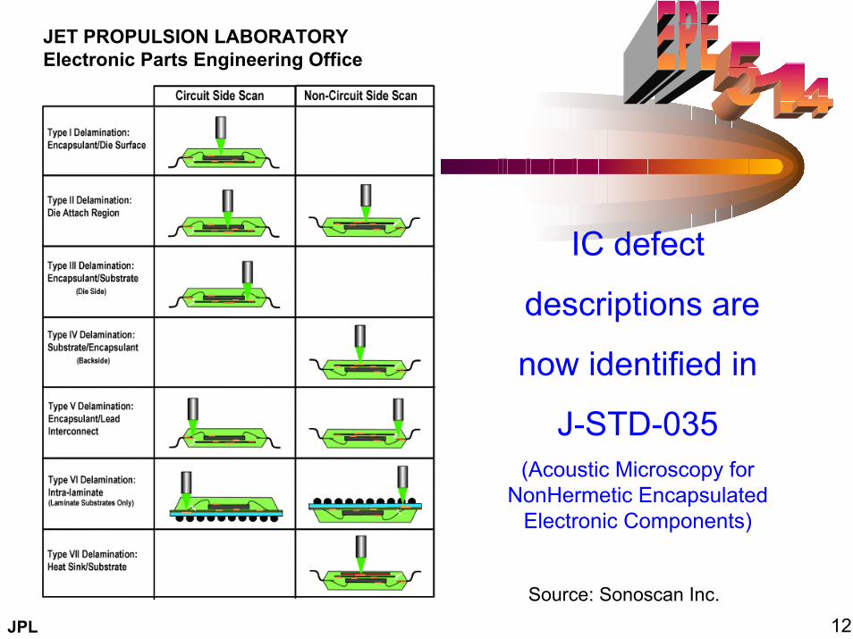
IC defect
descriptions are
now identified in
J-STD-035 (Acoustic Microscopy for
NonHermetic Encapsulated Electronic Components)
Source: Sonoscan Inc.12JPL
JET PROPULSION LABORATORYElectronic Parts Engineering Office
A New Failure Characterization Study
is Underway Utilizing Plastic Part C-SAM Rejects
Objectives:
• Identify C-SAM reject parts by criteria(s)
• Measure Material Properties including sonic test, IR, X-ray
• Apply extreme temperature cycle stresses
• Repeat Material Properties Measurements including C-SAM at different intervals
• Identify all failure mechanisms and risk rate C-SAM rejects
13JPL
JET PROPULSION LABORATORYElectronic Parts Engineering Office
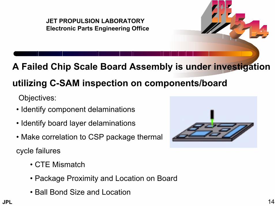
A Failed Chip Scale Board Assembly is under investigation
utilizing C-SAM inspection on components/board
• Identify component delaminations
• Identify board layer delaminations
• Make correlation to CSP package thermal
cycle failures
• CTE Mismatch
• Package Proximity and Location on Board
• Ball Bond Size and Location
Objectives:
14JPL

JET PROPULSION LABORATORYElectronic Parts Engineering Office
Summary:• Some reported concerns/risks anticipated with using PEMs having evidence of delamination can be minimized and possibly eliminated with nondestructive AMI (acoustic microscopy imaging).
• JPL’s existing screening flows for PEMs incorporates AMI 100% to enhance the reliability of parts used by JPL Projects when PEMs are the only choice available.
• Further investigations/studies are being conducted on individual components and board assemblies using AMI analysis. This information will provide more understanding of the correlation between delamination and component/ board failure mechanisms.
15JPL
JET PROPULSION LABORATORYElectronic Parts Engineering Office
Additional information can be found at:
http://cots.jpl.nasa.gov16JPL