commercial pv using the enphase m-series microinverter system
TRANSCRIPT

DESIGN GUIDE
Commercial PV Using the Enphase M-Series Microinverter System
Busch Stadium, Home of the St. Louis Cardinals

Enphase M-Series Commercial Design Guide for North America
2 Copyright 2015 Enphase Energy. All rights reserved. May 6, 2015
Contact Information
Enphase Energy Inc. 1420 N. McDowell Blvd. Petaluma, CA 94954
www.enphase.com
Contact us at http://enphase.com/support/ for design support or more information.
Other Information
Product information is subject to change without notice. All trademarks are recognized as the property of their respective owners.
Enphase equipment must be installed in accordance with all locally recognized electrical codes, including National Electrical Code (NEC), ANSI/NFPA 70.
User documentation is updated frequently; check the Enphase Support Center for the latest information.
Copyright © 2015 Enphase Energy Inc. All rights reserved.

Enphase M-Series Commercial Design Guide for North America
May 6, 2015 Copyright 2015 Enphase Energy 3
Table of Contents
Section 1: Enphase Commercial Design Fundamentals .............................................................................. 5 Introduction ...................................................................................................................................... 5 Enphase System Components and Concepts ................................................................................. 6 Limitless Scalability .......................................................................................................................... 8 Isolating Communication Domains .................................................................................................. 9
Using the Enphase LCF to Isolate Communication Domains ...................................................... 9 Using a Transformer to Isolate Communication Domains ........................................................... 9 Using an Aftermarket Filter to Isolate Communication Domains ................................................. 9 Do I Need an LCF, a Transformer, or Filter? ............................................................................. 10
Filtering Methods ............................................................................................................................ 11 Designing with Enphase Line Communication Filters ................................................................ 11 Designing with Transformers ..................................................................................................... 12 Designing with Aftermarket Power Line Filters .......................................................................... 14
Ampacity Calculations and Equipment Ratings ............................................................................. 16 240V Single-Phase Ampacity Calculation for Enphase Microinverters ..................................... 16 208V Three-Phase Ampacity Calculation for Enphase Microinverters ...................................... 16 480V Three-Phase Ampacity Calculation for Enphase Microinverters ...................................... 18
Revenue Grade Metering for Commercial Projects ....................................................................... 19 Requesting Design Support from Enphase Energy ....................................................................... 19 Design Tips for Success ................................................................................................................ 22 Building Virtual Arrays in Enlighten ................................................................................................ 23
Section 2: Calculating AC Line Voltage Rise for M215 and M250 Microinverters ...................................... 25 Recommendations ......................................................................................................................... 25 Background .................................................................................................................................... 25 What Contributes to Voltage Rise .................................................................................................. 26 Voltage Rise by Wire Section ........................................................................................................ 27 Engage Cable and Internal Voltage Rise ....................................................................................... 28
Engage Cable Types .................................................................................................................. 28 Voltage Rise within an Enphase Microinverter Branch Circuit ................................................... 28 Microinverter Branch Circuit and 208 VAC Engage Cable Voltage Rise Tables ....................... 29
Advantages of Center-Feeding AC Branch Circuits ...................................................................... 30 Conductor Lengths for Wire Sections ............................................................................................ 31 Voltage Rise Formula for a Three-Phase 208 VAC Installation..................................................... 31 Calculating Total VRise for M215 Three-Phase 208 VAC Installations ......................................... 32
Section 1: Internal VRise for 208 VAC Engage Cable ............................................................... 32 Section 2: VRise from the Array-Located Junction Box to the Microinverter Subpanel ............. 32 Section 3: VRise from the Microinverter Subpanel to the Main Service Meter (PCC) ............... 33 M215 Summary of Calculations for Three-Phase 208 VAC Applications .................................. 33
Calculating Total VRise for M250 Three-Phase 208 VAC Installations ......................................... 34 Section 1: Internal VRise 208 VAC Engage Cable .................................................................... 34 Section 2: VRise from the AC junction box to the Microinverter Subpanel ................................ 34 Section 3: VRise from the Microinverter Subpanel to the Main Service Meter (PCC) ............... 35 Summary of Wire Section Calculations for Three-Phase 208 VAC Applications ...................... 35
Conclusion ..................................................................................................................................... 35 Section 3: Grounding Considerations for Enphase M215 and M250 Installations ..................................... 36

Enphase M-Series Commercial Design Guide for North America
4 Copyright 2015 Enphase Energy. All rights reserved. May 6, 2015
GFP within the M250 and M215 Eliminates the Need for a GEC .............................................. 36 Original M215 Models and Grounding ....................................................................................... 36
Section 4: Commissioning for a Multi-Envoy Site ....................................................................................... 37 Commissioning Steps .................................................................................................................... 37
Provisioning the Envoy with the Installer Toolkit App ................................................................ 37 Provisioning the Envoy with the Device Scan ............................................................................ 38
Section 5: Networking and PLC Considerations for Commercial Projects ................................................. 39 PLC Considerations ....................................................................................................................... 39 LAN/WAN Guidelines for Envoy Communication .......................................................................... 39
DHCP and Self Assigned IP Address (169.254.x.x) .................................................................. 39 DHCP versus Static IP Addressing ............................................................................................ 39 MAC Filtering .............................................................................................................................. 40 Firewall Settings ......................................................................................................................... 40 Wireless Range Extenders with an Enphase System ................................................................ 40
Enphase Typical Commercial Deployment Networking Examples ................................................ 43 Typical LAN/WAN Network with an Enphase Envoy ................................................................. 43 Commercial Deployment with a Single LCF and Envoy Pair ..................................................... 44 Typical Commercial Deployment with Multiple LCFs and Envoys ............................................. 45 Ethernet Network and Wireless LAN ......................................................................................... 46 Wireless LAN Technologies ....................................................................................................... 46
Appendix A: Lightning and Surge Suppression in Commercial Systems ................................................... 49 Lightning Protection ....................................................................................................................... 49 Surge Suppression ......................................................................................................................... 49 Enphase Recommended Devices .................................................................................................. 49
Appendix B: Dropped Phase Hardware Solution ........................................................................................ 51 Dropped Phase Scenario ............................................................................................................... 51 Dropped Phase Hardware Solution ............................................................................................... 51
Appendix C: Fault Current Contribution in the M215 & M250 Microinverters ............................................. 53 Fault Current Contribution .............................................................................................................. 53
Calculating Fault Current Contribution from Enphase Microinverters ........................................ 53 Conclusion ..................................................................................................................................... 54
Appendix D: Total Rated-Current Distortion and Total Demand-Current Distortion ................................... 55 Conclusion ..................................................................................................................................... 55
Acronyms and Glossary .............................................................................................................................. 56

Enphase M-Series Commercial Design Guide for North America
May 6, 2015 Copyright 2015 Enphase Energy 5
Section 1: Enphase Commercial Design Fundamentals
Introduction The Enphase® Microinverter System™ is the world’s most technologically advanced inverter system for use in utility-interactive applications.
The Enphase Microinverter System delivers design flexibility, integrated intelligence, increased energy harvest, and system availability not found in a central inverter-based system. Deploying the M215™ or M250™ Microinverter Systems on commercial and utility scale projects is simple and cost effective. Join the thousands of solar integrators and developers who chose Enphase Microinverters for large-scale photovoltaic installations.
This design guide details tips and processes for designing commercial PV systems using M215 or M250 Microinverters.
Follow these guidelines to make your project as trouble free as possible, especially when designing systems larger than 100 kW or systems with more than one Enphase Envoy® Communications Gateway™. This guide also recommends best practices and lists requirements to help minimize costs, maximize performance, and ensure robust microinverter to Envoy communications.
The three key elements of an Enphase Microinverter System include the:
Enphase M215 or M250 Microinverter
Enphase Envoy Communications Gateway
Enphase Enlighten® web-based monitoring and analysis software platform
Installing these elements along with the ancillary components of the Enphase Microinverter System maximizes energy harvest, simplifies design, installation and management, and increases system reliability in your next commercial project.
Figure 1 The Enphase Microinverter System

Enphase M-Series Commercial Design Guide for North America
6 Copyright 2015 Enphase Energy. All rights reserved. May 6, 2015
Enphase System Components and Concepts This section describes Enphase Microinverter System components and concepts for you to use in your commercial design plans.
Activation Process: Activation is the process of connecting Enphase Microinverters to the Enlighten web-based monitoring software platform at https://enlighten.enphaseenergy.com. Enlighten provides monitoring for up to 4000 microinverters in one activated PV system. If your project contains over 4000 microinverters, then you can activate multiple PV systems in Enlighten for your project.
Bluetooth Scanner: Use a Bluetooth scanner paired with the Enphase Installer Toolkit to scan microinverter serial numbers quickly and accurately. You can also use the Installer Toolkit and a Bluetooth scanner to build virtual arrays and upload the array map directly to the Enlighten, and to provision the Envoy database with the scanned microinverters.
Center-Feed Method: The center-feed method separates an individual branch circuit into two sub-branch circuits on the same over current protection device (OCPD). This is a standard design practice with Enphase Microinverters and lowers overall wiring costs by reducing voltage drop and potentially avoiding the need to upsize distribution wiring. Section 2: Calculating AC Line Voltage Rise for M215 and M250 Microinverters on page 25 provides details.
Communication Domain: A communication domain is group of PV module and microinverter pairs that communicate with a common Envoy.
Engage Cable™: The Engage Cable is an innovative cabling system used to connect Enphase Microinverters. Engage Cable has a connector for each microinverter, with connectors placed every 1.025 meters for portrait applications, or 1.7 meters for landscape applications. The cable contains #12 THWN-2 conductors and is rated to feed a 20A circuit breaker. Engage Cable is available for single-phase or three-phase applications and must be ordered for the appropriate application. Engage Cable Types and the Engage Cable datasheet provide details.
Enlighten®: The Enlighten software platform offers web-based tools to manage Enphase Microinverter Systems. Use Enlighten to access and monitor your fleet of PV installations down to the individual module. Enlighten provides detailed diagnostics so that you can determine whether a system is performing as expected.
Enphase Line Communications Filter (LCF): When a project requires more than one Envoy, install an LCF on every communication domain. An LCF helps prevent cross-talk between Envoy communication domains and provides noise filtration from other site loads. Each LCF contains an Envoy inside the LCF enclosure. Locate the LCF near the communication domain it serves. Using an LCF limits the number of microinverters that can be installed in a communication domain to maintain the 100A continuous output rating. Designing with Enphase Line Communication Filters and the Enphase LCF data sheet provide specifications and details about deploying the Enphase LCF.
Envoy Communications Gateway: The Envoy Communications Gateway is a system monitoring device that monitors up to 600 Enphase Microinverters. The Envoy uses the power lines on site to communicate with each microinverter. The Envoy connects to the Internet through a broadband router and other networking components, and uploads microinverter data into Enlighten.
The Enphase Wireless Adapter (Wi-Fi USB stick), included with the Envoy model ENV-120-02, allows the Envoy to transmit Enphase Microinverter System data through the on-site wireless network.
Using the wireless adapter simplifies Envoy installation and reduces system commissioning time. With the Enphase wireless adapter, you can connect the Envoy to the Internet either with the Wi-Fi WPS button on the wireless router, or by manual configuration using the Envoy local interface.
Filtration of Communication Domains: If you have more than one communication domain with multiple Envoys that are tied to a common service panel or off of a single transformer, take steps to prevent cross-talk between the communication domains. Install an Enphase LCF, a commercially available power line filter, or a transformer between each microinverter subpanel and the main photovoltaic load center. You must also physically separate the

Enphase M-Series Commercial Design Guide for North America
May 6, 2015 Copyright 2015 Enphase Energy 7
conduits and wires of one communication domain from another communication domain by at least 12 inches.
Installer Toolkit: The Enphase Installer Toolkit is an iOS app that provides installers with onsite system configuration capabilities, eliminating the need for a laptop and improving installation efficiency. You can use the app to:
Connect to the Envoy over a wireless network for faster system setup and verification.
View and email a summary report that confirms a successful application of a grid profile, if required.
Pair with a Bluetooth-enabled scanner to scan microinverter serial numbers and sync system information with Enlighten monitoring software.
Provision the Envoy databases with the scanned microinverter serial numbers.
M215 Microinverter: The M215 Microinverter is 96.5% efficient and works with 60 cell modules up to 270 watts STC. The new M215, released in January, 2014, does not require a Grounding Electrode Conductor (GEC) because the DC circuit is isolated and insulated from ground. The M215 is rated for a continuous output of 215 watts. The M215 automatically detects the utility voltage and exports power to either 208 VAC or 240 VAC utility services. Each branch circuit of M215s feeds a 20A circuit breaker.
Maximum number of M215s when protected with a 20 A OCPD
Service type Max M215s per AC branch circuit
Single- phase 240 VAC 17
Three phase 208 VAC 25
M250 Microinverter: The M250 Microinverter is 96.5% efficient and works with most 60 cell modules up to 300 watts STC. The M250 does not require a Grounding Electrode Conductor (GEC) because the DC circuit is isolated and insulated from ground. The M250 is rated for a continuous output of 240 watts. The M250 automatically detects the utility voltage and exports power to either 208 VAC or 240 VAC utility services. Each branch circuit of M250s feeds a 20A circuit breaker.
Maximum number of M250s when protected with a 20 A OCPD
Service type Max M250s per AC branch
Single- phase 240 VAC 16
Three phase 208 VAC 24
Main Photovoltaic Load Center: An electrical load center that feeds multiple microinverter subpanels.
Microinverter Subpanel: A microinverter subpanel is an electrical load center dedicated to a single communication domain. The microinverter subpanel contains multiple 20A circuit breakers, each feeding one microinverter output branch circuit.
Power Line Communication: Power line communication (PLC) technology enables signal transmission over the same AC lines used for on-site power distribution. Enphase Microinverters and the Envoy Communication Gateway use power line communication in the 100–150 KHz range to send and receive data.
Power Line Communication Bridges: If the Envoy needs to be located away from the router at a distance where an Ethernet cable is not practical, use power line communication bridges (Ethernet bridges), an Enphase wireless adapter, or purchase a wireless Ethernet bridge. Bridges allow the Envoy to communicate with the broadband router without the need for additional Ethernet cabling.
Power Line Filter: Use power line filters or EMC filters to isolate multiple Envoy communication domains or to filter electrical noise from site loads.

Enphase M-Series Commercial Design Guide for North America
8 Copyright 2015 Enphase Energy. All rights reserved. May 6, 2015
Separation of Communication Domains: To prevent induction of communication signals between conduit and wire runs, physically separate each communication domain from other communication domains. The conduits and wiring running within a communication domain must be physically separate from the conduits and wiring of other communication domains. Conduits and wiring on the array side of the filters should be separated by at least 12 inches.
Startup Procedure: By following the startup procedures detailed in “Section 4: Commissioning” on page 37 of this document, you help prevent cross talk between communication domains in a commercial installation. Scan the devices in one communication domain using the domain’s Envoy. When that scan process is complete, end the Envoy device scan, and then commission the next communication domain.
Transformer: A transformer is often required to interconnect commercial photovoltaic projects to the utility grid. Use transformers to connect Enphase Microinverter systems to 480V and higher utility services, to offset voltage rise over long cable runs, and to lower wire costs for long transmission runs. A transformer is also an excellent filter of electrical noise and communication signals and provides isolation of communication domains. In addition, a transformer generally has adjustable taps that allow for adjustments to the utility voltage.
Figure 2 Commercial Scale Enphase Project
Limitless Scalability The size of an Enphase system is practically limitless. An Enphase commercial-scale project generally includes a main panel board or PV load center that feeds multiple microinverter subpanels distributed across the system. This scalable design is only limited by the utility grid that feeds the site.
The number of Envoy system monitors needed generally determines the number of microinverter subpanels to install. Since the Envoy is rated to monitor the output of up to 600 microinverters, you can divide your system into sub-systems of 600 microinverters or fewer.
A common design would be to connect each sub-system of 600 microinverters to a 600A, 208/120V panel board, but it may be more cost effective to installer fewer microinverters onto a 400A panel board. 532 M215s or 480 M250s would maximize the ampacity of a 400 A panel board. You can install smaller sub-systems, but that may not make sense for larger projects.

Enphase M-Series Commercial Design Guide for North America
May 6, 2015 Copyright 2015 Enphase Energy 9
Isolating Communication Domains If you install multiple Envoys off of a single utility transformer, you will likely need a filter to isolate each Envoy into a separate communication domain. This is particularly true for large-scale projects. Use transformers, LCFs, or aftermarket filters to isolate communication domains.
In a large-scale project, each sub-system generally consist of modules, microinverters, cables, branch circuit breakers, a microinverter subpanel or panel board, and a filter. A filter prevents power-line communication signals from one Envoy communication domain from interfering with another Envoy communication domain. The filter also offers the added benefit of eliminating electrical noise from site loads.
With multiple communication domains, the total number of filters can be one less than the total number of communication domains. That is, if all other communication domains have filters, you can build one communication domain without a filter (n – 1).
If your system contains fewer than 600 microinverters with a single Envoy on-site (a single communication domain), you do not need a filter to isolate communication domains. A system of 600 microinverters has an AC inverter output rating of 129kW or 150kW. For systems with fewer than 600 microinverters, the content in this section is likely to not apply.
Refer the following sections and Do I Need an LCF, Filter, or Transformer to help determine filtering needs for your installation.
Using the Enphase LCF to Isolate Communication Domains
The Enphase LCF is convenient to work with because it provides communication domain filtering. The LCF is an outdoor enclosure that houses an Envoy. This eliminates the need to install a separate receptacle for the Envoy. The LCF is rated for 100A of continuous microinverter current and must be protected by a 125A circuit breaker or smaller. If installing LCFs, limit each communication domain to 166 M215s or 150 M250s at 208V due to the ampacity (ampere capacity) of the filter.
Using a Transformer to Isolate Communication Domains
Transformers also provide excellent filtering between Enphase communication domains. A 480 V, 600 V, or medium voltage interconnection requires a transformer to step the voltage down to 208/120 Wye. If the project does not require transformers, or if a single, central transformer is selected, then you can filter Envoy communication domains with Enphase LCFs or commercially available power line filters.
Using an Aftermarket Filter to Isolate Communication Domains
For some larger systems, it is convenient to install commercially available power line filter products. Power line filters are available in a variety of ampacities and voltage configurations. This variety of ratings available allows maximum flexibility in your design choices.

Enphase M-Series Commercial Design Guide for North America
10 Copyright 2015 Enphase Energy. All rights reserved. May 6, 2015
Do I Need an LCF, a Transformer, or Filter?
Table 1 Microinverters per LCF
Microinverter Model Nominal Watts
System Voltage
Microinverters per LCF AC System Size in kW
M215-60 at 240 VAC 215 240 111 24
M215-60 at 208 VAC 215 208 166 36
M250-60 at 240 VAC 240 240 100 25
M250-60 at 208 VAC 240 208 150 37.5
Divide the number from this chart into the total number of microinverters installed, and round up to determine the total numbers of LCFs needed.
NOTE: If the system is relatively large, consult with a Professional Engineer to determine if LCF usage could be optimized based on existing switchgear.

Enphase M-Series Commercial Design Guide for North America
May 6, 2015 Copyright 2015 Enphase Energy 11
Filtering Methods This section provides information on various filtering methodologies.
Designing with Enphase Line Communication Filters
Figure 3. Enphase LCF
To ensure reliable monitoring, locate LCF units close to the microinverters. For commercial roof-mounted systems, the microinverter sub-panels and LCFs are generally located on the roof. For ground-mounted systems, the microinverter subpanels and LCFs are generally at or near the communication domain. Provide an Ethernet cable between each Envoy and an Internet port on the network router. This often requires conduits and LAN/Ethernet cables to each LCF.
The LCF has a maximum OCPD rating of 125 Amps. Per NEC 690.8(A)(1), connect up to 100 Amps of continuous inverter output current to the microinverter subpanel filtered by the LCF. The 100 Amp rating limits each communication domain to fewer microinverters than otherwise allowed with an Envoy. Table 1 lists the number of microinverters allowed per LCF.
Enphase M-Series Commercial Design Guide for North America
12 Copyright 2015 Enphase Energy. All rights reserved. May 6, 2015
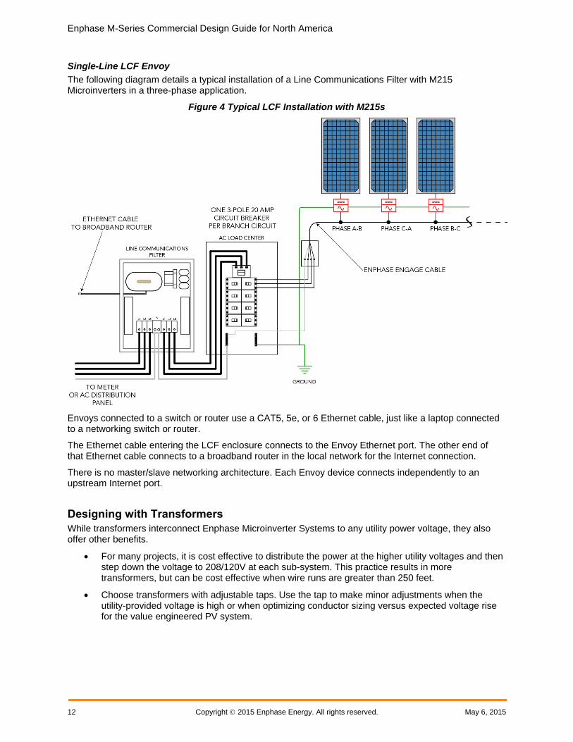
Single-Line LCF Envoy
The following diagram details a typical installation of a Line Communications Filter with M215 Microinverters in a three-phase application.
Figure 4 Typical LCF Installation with M215s
Envoys connected to a switch or router use a CAT5, 5e, or 6 Ethernet cable, just like a laptop connected to a networking switch or router.
The Ethernet cable entering the LCF enclosure connects to the Envoy Ethernet port. The other end of that Ethernet cable connects to a broadband router in the local network for the Internet connection.
There is no master/slave networking architecture. Each Envoy device connects independently to an upstream Internet port.
Designing with Transformers
While transformers interconnect Enphase Microinverter Systems to any utility power voltage, they also offer other benefits.
For many projects, it is cost effective to distribute the power at the higher utility voltages and then step down the voltage to 208/120V at each sub-system. This practice results in more transformers, but can be cost effective when wire runs are greater than 250 feet.
Choose transformers with adjustable taps. Use the tap to make minor adjustments when the utility-provided voltage is high or when optimizing conductor sizing versus expected voltage rise for the value engineered PV system.

Enphase M-Series Commercial Design Guide for North America
May 6, 2015 Copyright 2015 Enphase Energy 13
It is common to specify high-efficiency or ultra-high efficiency, general purpose, dry-type transformers for an Enphase Microinverter System. It is not necessary to specify power factor correcting transformers or K-factor transformers.
You will need to specify the transformer kVa size meet the inverter output in kW AC. Some additional deratings, such as adjustments for power factor (0.95) and temperature may apply. Refer to the transformer manufacturer’s specifications for transformer sizing.
Most transformers for Enphase systems are specified as delta on the primary side and as 208/120 Wye on the secondary side. The 208/120 Wye configuration is necessary for the operation of microinverters. Even if the utility voltage is Wye, a 480/277 Wye service, for example, it is still best to provide a delta configuration with no neutral to the primary side of the transformer. This configuration works well, lowers wire costs, and is recommended by the manufacturers of transformers for improved performance.
Figure 5 3-Phase Delta and Wye Wiring
Image from Mike Holt Forums. No date. http://forums.mikeholt.com/showthread.php?t=128508.
The following table lists utility voltage values and transformer requirements.
Table 2 Voltage Configurations and Transformer Specifications
Utility Voltage Configurations
Nominal Voltages Between the Lines and Neutral/Ground
L1 to L2 L2 to L3 L3 to L1 L1 to N/G L2 to N/G L3 to N/G
208/120 Wye 208 208 208 120 120 120
No Transformer would be specified for interconnection
480/277 Wye 480 480 480 277 277 277
Specify a 480Delta:208/120Wye transformer
480 Delta 480 480 480 - - -
Specify a 480Delta:208/120Wye transformer
240 Delta 240 240 240 - - -
Specify a 240Delta:208/120Wye transformer
240 High-Leg Delta 240 240 240 120 120 208
Specify a 240Delta:208/120Wye transformer (see Note)

Enphase M-Series Commercial Design Guide for North America
14 Copyright 2015 Enphase Energy. All rights reserved. May 6, 2015
Utility Voltage Configurations
Nominal Voltages Between the Lines and Neutral/Ground
L1 to L2 L2 to L3 L3 to L1 L1 to N/G L2 to N/G L3 to N/G
600/347 Wye 600 600 600 347 347 347
Specify a 600Delta:208/120Wye transformer
Note: Many utilities allow a small, single-phase system installed on the 120/240V phase of a high-leg delta system. This can imbalance a three-phase transformer and may be problematic for systems larger than 6 kW. It is best practice to consult your utility about acceptable levels of imbalance.
Designing with Aftermarket Power Line Filters
Enphase has approved a number of aftermarket filters for use with Enphase Microinverter Systems. The approved filters effectively filter noise and communication signals in the 144 kHz range, the transmission frequency of Enphase power line communications.
Figure 6 Aftermarket Filter for a Solar Parking Lot
While aftermarket filters are simple to install, Enphase recommends that you follow these guidelines for installation:
Wire the filters in-line between the utility and microinverter subpanels, at or near the subpanels.
Install the filters in an 8” deep electrical enclosure, such as an 8”x8”x48” electrical gutter and sized to meet applicable codes; such as NEC Article 314.28 for the US.
Verify that the current rating of the filter meets the ampacity of the rated inverter output current and that it is protected by an appropriate over current protection device (OCPD). The filter ampacity may need to be adjusted for temperature correction factors as specified by the manufacturer. This is particularly important if the filters are installed in direct sunlight or in high thermal conditions as typically these filters start to derate ampacity at temperatures over 50°C.

Enphase M-Series Commercial Design Guide for North America
May 6, 2015 Copyright 2015 Enphase Energy 15
Enphase Recommended Filters
Enphase Energy recommends the following power line filter products for single or three-phase applications. Like all electronic parts they are heavily discounted at volume so to talk to your distributor about total number of filters required for your design.
Table 3. Recommended Filters
Manufacturer Model Number Rated Amperage
Radius
Radius is part of Astrodyne TDI. Contact [email protected] for more information or to order.
RP428-200 200A
RP428-300 300A
RP428-400 400A
RP428-600 600A
Schaffner
Schaffner EMC 52 Mayfield Avenue Edison NJ 08837
(800) 367-5566
Schaffner Datasheet FN3280 20110503
FN-3280H-200-40 200A
FN-3280H-400-99 400A
FN-3280H-600-99 600A
FMBD-B92F-K012 200A
Schaffner filters are in-stock and are available for purchase from Digi-key or from any Schaffner distributor listed on www.schaffnerusa.com.

Enphase M-Series Commercial Design Guide for North America
16 Copyright 2015 Enphase Energy. All rights reserved. May 6, 2015
Ampacity Calculations and Equipment Ratings For three-phase sites, design the installation with a balanced number of microinverters on each phase. To calculate the ampacity (ampere capacity or current) on a given conductor you must determine the number of microinverters powered by that set of conductors.
NOTE: Apply a 1.25 multiplier to the calculated result to size the OCPD per NEC Article 690.8(A)(3) or local standards. The 1.25 multiplier is used in the following ampacity calculations.
240V Single-Phase Ampacity Calculation for Enphase Microinverters
The equation to calculate ampacity (circuit current) for one branch in a 240V single-phase system is:
Amps per branch = (Maximum output power of microinverter) × (number of microinverters) ÷ (240 volts)
The equation to determine OCPD sizing is:
OCPD Sizing = (Maximum output power of microinverter) × (number of microinverters) ÷ (240 volts) × 1.25
Example: M215 in a 240V Single-Phase System
An M215 Microinverter has a maximum output power of 215 Watts AC. If there are 17 microinverters in a branch, then the ampacity for this branch is:
215 W × 17 ÷ 240 volts = 15.3 amps
The OCPD sizing is: 15.3 amps × 1.25 = 19.1 amps
Example: M250 in a 240V Single-Phase System
An M250 Microinverter has a maximum output power of 240 Watts AC. If there are 16 microinverters in a branch, then the ampacity for this branch is:
240 W × 16 ÷ 240 volts = 16 amps
The OCPD sizing is: 16 amps × 1.25 = 20 amps
208V Three-Phase Ampacity Calculation for Enphase Microinverters
The equation to calculate ampacity for one branch in a 208V three-phase system is:
Current (amps per branch) = (Maximum output power of microinverter) × (number of microinverters) ÷ (208 volts× 1.732)
The equation to determine OCPD sizing for a three-phase system is:
OCPD Sizing = (Maximum output power of microinverter) × (number of microinverters) ÷ (208 volts× 1.732) × 1.25
Use these calculations to determine ampacity in three-phase systems as shown in the following sections.
NOTE: Each of the three hot conductors in a balanced three-phase system carries this current. The neutral does not carry any current, but is used for microinverter communications and voltage sensing.
Example: M215 Microinverters on a Single Circuit for a 208/120V Three-Phase System
The ampacity calculation for a branch circuit of 24 M215 microinverters at a three-phase 208V site is as follows:
Current (amps per branch) = 215 watts/microinverter × 24 microinverters ÷ (208 volts × 1.732) = 14.32 amps

Enphase M-Series Commercial Design Guide for North America
May 6, 2015 Copyright 2015 Enphase Energy 17
The ampacity result is 14.32 Amps.
OCPD sizing = 14.32 amps × 1.25 = 17.9 amps
A branch circuit of 24 M215 Microinverters requires a three-pole, 20A circuit breaker or OCPD.
Example: M215 Microinverters on Multiple Circuits for a 208/120V Three-Phase System
Calculating the ampacity for other wire sections is same as for a single circuit, but you must know the total number of microinverters on the combined wire run.
In this example, a microinverter subpanel feeds a total of 528 microinverters divided into 22 branch circuits with 24 microinverters per circuit. The 22 3-pole circuit breakers will likely require two load centers in parallel to provide enough breaker positions. The calculation is as follows:
Current (amps per branch) = 215 Watts/microinverter × 528 microinverters ÷ (208 volts × 1.732) = 315.11 amps
The ampacity result is 315.11 amps.
OCPD sizing = 315.11 Amps × 1.25 = 393.89 amps
A photovoltaic system with 528 M215 Microinverters requires a 400A (minimum) circuit breaker or OCPD.
NOTE: Each of the three hot conductors in a balanced three-phase system carries this current. The neutral does not carry any current, but is used for microinverter communications and voltage sensing. For this reason, the neutral can be downsized to the size of the EGC as per 705.95(B).
Example: M250 Microinverters on a Single Circuit for a 208/120V Three-Phase System
An M250 Microinverter has a maximum output power of 240 Watts AC. The ampacity calculation for a branch circuit of 24 M250 microinverters at a three-phase 208V site is as follows:
Current (amps per branch) = 240 watts/microinverter × 24 microinverters ÷ (208 volts × 1.732) = 15.99 amps
The ampacity result is 15.99 Amps.
OCPD sizing = 15.99 amps × 1.25 = 19.9 amps
A branch circuit of 24 M250 Microinverters requires a three-pole, 20A circuit breaker or OCPD.
Example: M250 Microinverters on Multiple Circuits for a 208/120V Three-Phase System
Calculating the ampacity for other wire sections is same as for a single circuit, but you must know the total number of microinverters on the combined wire run.
In this example, an M250 Microinverter subpanel feeds a total of 600 microinverters divided into 25 branch circuits with 24 microinverters per circuit. The 25 3-pole circuit breakers will likely require two load centers in parallel to provide enough breaker positions, or an 82 position, 600A panel board may be specified. The ampacity calculation for that system is as follows:
Current (amps per branch) = 240 Watts/microinverter × 600 microinverters ÷ (208 volts × 1.732) = 399.72 amps
The ampacity result is 399.72 amps.
OCPD sizing = 399.72 amps × 1.25 = 499.65 amps
A photovoltaic system with 600 M250 Microinverters requires a 500 A (minimum) circuit breaker or OCPD.

Enphase M-Series Commercial Design Guide for North America
18 Copyright 2015 Enphase Energy. All rights reserved. May 6, 2015
NOTE: Each of the three hot conductors in a balanced three-phase system carries this current. The neutral does not carry any current, but is used for microinverter communications and voltage sensing. For this reason, the neutral can be downsized to the size of the EGC as per 705.95(B).
480V Three-Phase Ampacity Calculation for Enphase Microinverters
The utility voltage from line to line determines the exact calculation, but the equation to calculate ampacity for one branch in a 480V three-phase system is:
Current (amps per branch) = (Maximum output power of microinverter) × (number of microinverters) ÷ (480 volts× 1.732)
The equation to determine OCPD sizing for a three-phase system is:
OCPD Sizing = (Maximum output power of microinverter) × (number of microinverters) ÷ (480 volts× 1.732) × 1.25
If the utility voltage at the point of common coupling (PCC) is greater than 208V, then your PV system requires a transformer. It is often cost effective to locate the transformer at the array or sub-array, and then transmit the power at the higher utility voltage. The feed from the PCC to the sub-array generally contains the three phase conductors and a ground wire, but the neutral is unnecessary for this wire section.
Example: M215 Microinverters on Multiple Circuits for 480V Three-Phase
The calculation for an M215 microinverter subpanel that is feeds 528 microinverters at 480V is as follows:
Current (amps per branch) = 215 Watts/microinverter × 528 microinverters ÷ (480 volts× 1.732) = 136.55
The ampacity result is 136.55 amps.
OCPD sizing = 136.55 Amps × 1.25 = 170.69 amps
A photovoltaic system with 528 M215 Microinverters at a 480V Three-Phase site requires a 175A (minimum) circuit breaker or OCPD.
NOTE: Each of the three hot conductors in a balanced three-phase system carries this current. The neutral does not carry any current, but is used for microinverter communications and voltage sensing.

Enphase M-Series Commercial Design Guide for North America
May 6, 2015 Copyright 2015 Enphase Energy 19
Revenue Grade Metering for Commercial Projects Revenue grade metering is often required for commercial projects that are financed or receive incentives from government organizations. These projects usually require metering accuracy within 2% to meet revenue grade requirements. Incentive programs also require that a Performance Data Provider provide monthly production reporting. Even though the Enphase Envoy rated accuracy is only within 5%, it can be paired with 2% rated revenue grade meters to meet reporting requirements.
For your three-phase and large-scale projects, you can install revenue grade, web-enabled meters from Energy Tracker LLC to communicate with the Envoy. Revenue grade production displays in Enlighten. Enphase describes the Envoy paired with the Energy Tracker meters in the application note, Performance Based Incentive (PBI) Requirements.
You can find out more about Energy Tracker meters on the Energy Tracker LLC website.
Enphase provides a metering and management solution which includes a GE i210 Revenue Grade Meter, but this solution is only for single-phase applications, rated for 200 amps, and is primarily for residential applications. You can find out more about the Enphase Metering and Management Solution on www.enphase.com/products/metering.
A number of meter manufacturers provide 2% revenue grade meters and are also established as Performance Data Providers. Some state SREC programs and incentive programs have generated lists of eligible data providers. It is the integrator’s or developer’s responsibility to procure the reporting service.
Requesting Design Support from Enphase Energy The Enphase Energy Commercial Design Team and Customer Service Team are available to support commercial integrators throughout the design, commissioning, and activations process. It is always easier to solve problems during the design process than after the system is built. The following resources are available for commercial design and system support:
Enphase offers free webinars on various aspects of commercial-scale PV deployments. You can register for these webinars on the Enphase Training page.
The Enphase Commercial team is available to review your commercial design and advise you on design details and best practices. Speak to your sales account manager about receiving design support or contact the team. To receive a comprehensive design review, please provide:
An electrical schematic of the proposed electrical system including:
o total system size
o main service voltage and current ratings
o module, microinverter, and racking specifications
o wire specifications
o Envoy and networking details
o specification of transformers, LCFs, or aftermarket power line filters
A detailed site plan or roof plan showing the locations of the main service panels, subpanels, transformers, electrical equipment, and arrays.
Any special considerations that may impact the design, installation, or permit process.

Enphase M-Series Commercial Design Guide for North America
20 Copyright 2015 Enphase Energy. All rights reserved. May 6, 2015
Figure 7 Sample Electrical Schematic

Enphase M-Series Commercial Design Guide for North America
May 6, 2015 Copyright 2015 Enphase Energy 21
Figure 8 Sample Site Plan

Enphase M-Series Commercial Design Guide for North America
22 Copyright 2015 Enphase Energy. All rights reserved. May 6, 2015
Design Tips for Success Ensure good Envoy communications with the microinverters and communications domains.
o Physically separate conduits and wires between multiple communication domains to prevent communication signals from one Envoy interfering with the communication signals of another. Signals can be inducted from one set of wires to another, even with metal conduit. Enphase recommends separating the conduits by 12 inches to prevent cross-communication.
o Create a complete set of installation documents as shown in Enphase Array Map, “Figure 10. Example of an Installation Map” and “Figure 7 Sample Electrical Schematic”. These help in system troubleshooting, especially in the case of cross-domain communications traffic issues.
o Clearly identify communications domains and note the microinverter serial numbers in each domain.
o Verify that the Envoy displays a communication level of at least three bars. If not, troubleshoot the system as described in the Enphase Troubleshooting Guide before installing additional systems, LCFs, Envoys or microinverters. Good communications are vital for effective large site operation. Poor communications generate missed messages, retries, and delays in collecting microinverters production data. This leads to spotty production graphs in Enlighten.
Refer to each Microinverter Installation Manual as part of your planning and design process. Follow the guidelines and instructions during microinverter installation, including:
o Install the Enphase Microinverter under the module, out of rain and sun. Do not mount the microinverter in a position that allows long-term exposure to direct sunlight or in a vertical orientation that allows water to collect in the DC connector recess.
o Installing the Enphase Microinverter black side up or vertically, with the DC connectors facing up, is not permitted.
Turn on each system individually or provision the Envoy databases using the Array Gun and Installer Toolkit application on your IOS device. Disable the Device Scan before commissioning another system on the same utility transformer.
When multiple Envoys are located on a single utility transformer, ensure that each Envoy database is populated only with the microinverter serial numbers in that communication domain. Commissioning each Envoy and associated system separately. After commissioning each system, use the Envoy to Disable the Device Scan before commissioning another system. (Commissioning for a Multi-Envoy Site in Section 4 guides you through this process)
Calculate voltage drop from the PCC (Point of Common Coupling) all the way to the microinverters (Section 2: Calculating AC Line Voltage Drop for M215 Microinverters with Engage™ Cables)
o Calculate each circuit section independently.
o Keep total voltage drop below 2% to avoid nuisance tripping.
Follow LCF installation requirements.
o Combine branch circuits near the array using a load center.
o Locate the LCF near the load center and run a single conductor back to the main.
o Keep conductors from other communications domains physically separate . (See Section 5 for details).
Run Ethernet during installation rather than as an afterthought:
o Consider hiring a third party IT company to help.
o Provide an outbound port and an Ethernet connection for each Envoy. You can find out more in LAN/WAN Guidelines for Envoy Communication.
Level: [ ] Devices: 25
Enphase M-Series Commercial Design Guide for North America
May 6, 2015 Copyright 2015 Enphase Energy 23
Ensure that the site meets Internet connectivity requirements.
o Install an always-on connection to the Internet. When the Internet connection is not on, the Envoy stores data. Then, when the connection returns, the Envoy sends stored data while simultaneously collecting and processing large amounts of live data. This delays data collection and transmission, and impedes the display of the most recent data in Enlighten.
o For most sites, Enphase does not recommend using 3G or 4G cellular modems for Internet connectivity to the Envoy. The two disadvantages to using cellular at this time are that the 3G or 4Gcommunications link is poor (uplink speed is too slow, and the latency is too high), and the data plan cost is high. One Envoy at a site with 500 microinverters requires about 240 MB of data usage every month. For this usage level, Enphase recommends using Ethernet bridges or Wi-Fi with DSL, Cable Modem, or T1 Internet access. Dial-up, satellite, or 3G/4G is insufficient. Some exceptions may apply so contact your Enphase Energy Field Applications Engineer for design guidelines.
Properly register and activate the system online. Bring the site up on Enlighten:
o The Array Gun provides a convenient way to scan the bar codes of microinverters and upload the maps to Enlighten with a compatible iPhone or iTouch device. You can download the Enphase Installer Toolkit App from the Apple Store.
o Use the Enphase Installer Toolkit App to provision the Envoy database with the appropriate microinverter serial numbers, instead of an Envoy device scan.
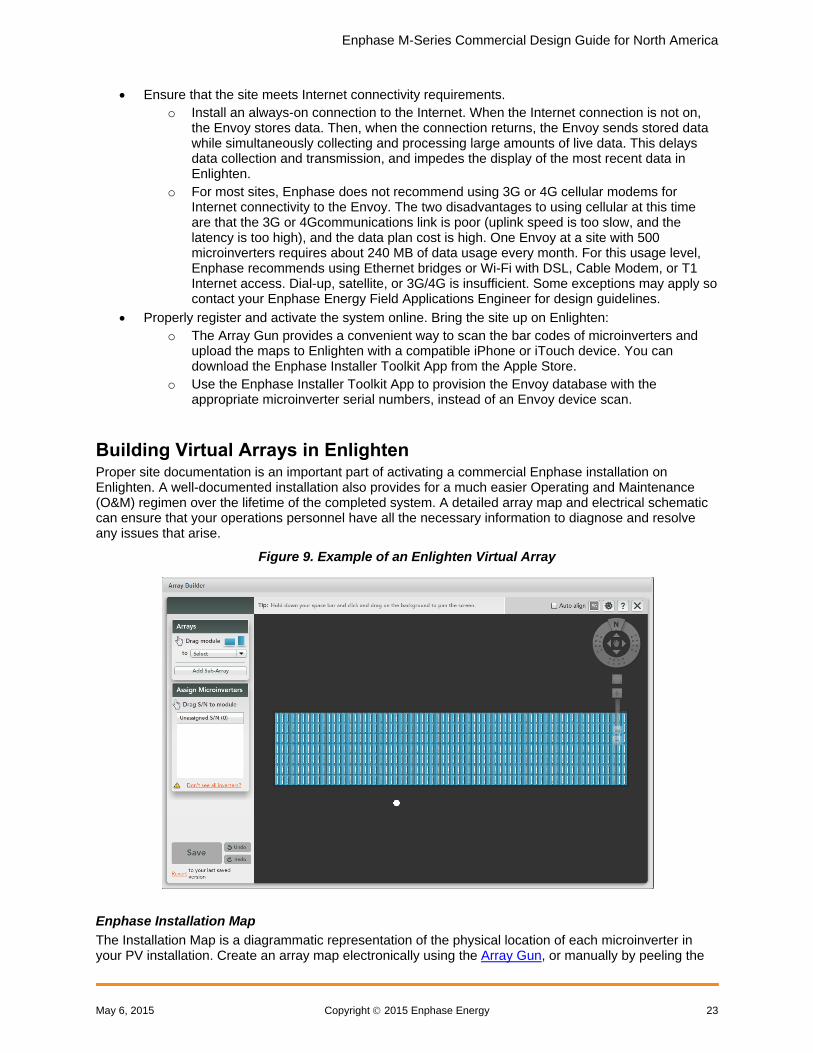
Building Virtual Arrays in Enlighten Proper site documentation is an important part of activating a commercial Enphase installation on Enlighten. A well-documented installation also provides for a much easier Operating and Maintenance (O&M) regimen over the lifetime of the completed system. A detailed array map and electrical schematic can ensure that your operations personnel have all the necessary information to diagnose and resolve any issues that arise.
Figure 9. Example of an Enlighten Virtual Array
Enphase Installation Map
The Installation Map is a diagrammatic representation of the physical location of each microinverter in your PV installation. Create an array map electronically using the Array Gun, or manually by peeling the
Enphase M-Series Commercial Design Guide for North America
24 Copyright 2015 Enphase Energy. All rights reserved. May 6, 2015
serial number labels from the microinverters and placing the labels on the installation map. You then use this map to build a virtual array in Enlighten. When activating a system in Enlighten, build the systems with less than 1,000 microinverters per system, with some consideration for the shape of the arrays.
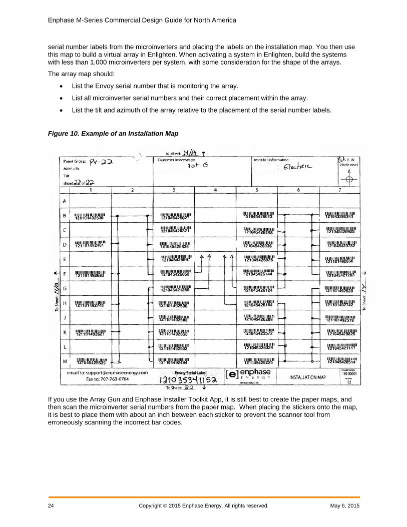
The array map should:
List the Envoy serial number that is monitoring the array.
List all microinverter serial numbers and their correct placement within the array.
List the tilt and azimuth of the array relative to the placement of the serial number labels.
Figure 10. Example of an Installation Map
If you use the Array Gun and Enphase Installer Toolkit App, it is still best to create the paper maps, and then scan the microinverter serial numbers from the paper map. When placing the stickers onto the map, it is best to place them with about an inch between each sticker to prevent the scanner tool from erroneously scanning the incorrect bar codes.

Enphase M-Series Commercial Design Guide for North America
May 6, 2015 Copyright 2015 Enphase Energy 25
Section 2: Calculating AC Line Voltage Rise for M215 and M250 Microinverters This section describes voltage rise guidelines for dedicated PV branch circuits and methods for calculating the AC line voltage rise (or voltage drop) with M215 or M250 Microinverters installed with the Enphase Engage Cable for balanced three-phase 208 VAC installations. You can find calculations for 240V single-phase systems in the Enphase voltage rise technical brief found http://enphase.com/support.
The application of proper voltage rise calculations in your site plan will help to prevent nuisance voltage out-of-range trip issues due to high line voltage conditions. Less resistance in conductors also results in less heat at the terminals, less power loss, and improved performance of the PV system.
When designing circuits for electrical loads, these calculations are commonly called voltage drop. But PV systems with inverters generate electricity instead of consume electricity. Since voltage actually rises at the AC terminals of inverters, this technical brief refers to these calculations as voltage rise (VRise).
Recommendations To minimize voltage rise issues, Enphase recommends that you apply these guidelines when planning your system:
The total VRise in the AC wiring should be less than 2%, which includes less than 1% VRise in the Engage Cable. Use the calculation examples in Calculating Total Voltage Rise for Three-Phase Installations to determine VRise values for your system. A good practice is to maintain less than 1% VRise in the Engage Cable.
Center-feed the branch circuit to minimize voltage rise in a fully-populated branch. Since the VRise is nonlinear, reducing the number of microinverters in a branch circuit greatly reduces the voltage measured at the last microinverter in the branch. To center-feed a branch, divide the circuit into two sub-branch circuits protected by a single overcurrent protection device (OCPD). Find out more in Advantages of Center-Feeding AC Branch Circuits.
Use the correct wire size in each wire section. Using undersized conductors can result in nuisance tripping of the microinverter anti-islanding function when an AC voltage out-of-range condition occurs. What Contributes to Voltage Rise provides more information.
You can use the calculations in this section to calculate VRise values for your project.
Background The IEEE 1547 standard requires that grid-tied or utility-interactive inverters cease power production if voltage measured at the inverter terminal exceeds +10% or -12% of nominal. Enphase Microinverters, like all utility-interactive inverters, sense voltage and frequency from the AC grid and cease exporting power when voltage or frequency from the grid is either too high or too low.
If the voltage measured is outside the limit, the Enphase Microinverter enters an AC Voltage Out-Of-Range (ACVOOR) condition and ceases to export power until this condition clears. Besides voltage variations from the AC grid, voltage changes within system wiring can also contribute to VRise and could cause microinverters to sense an over-voltage condition and cease operation.
The Enphase Microinverter reference point for voltage measurement is at the microinverter AC output. Since the microinverter is located at the array, and the point of common coupling (PCC) is generally at the site load center, the distance from the microinverter AC output to the PCC could be substantial.
All components within system wiring contribute to resistance and must be considered when calculating the total VRise. The main factors that determine voltage rise in an Enphase Microinverter system are: 1) distance from the microinverters to the PCC, and 2) conductor size. What Contributes to Voltage Rise provides details.

Enphase M-Series Commercial Design Guide for North America
26 Copyright 2015 Enphase Energy. All rights reserved. May 6, 2015
All resistances of the system components are in series, and are cumulative. Since the same current is flowing through each resistance, the total VRise is simply the total current times the total resistance. In a PV system, calculate total VRise as follows:
For a single-phase system, total resistance is equal to two times the one-way resistance.
For a three-phase system, each of the three line currents and resistances are calculated and then combined.
There is also some resistance associated with each OCPD (Over Current Protection Device), typically a circuit breaker.
Typically, you can quantify the voltage rise of three distinct wire sections and several wire terminations, as described in Voltage Rise by Wire Section.
What Contributes to Voltage Rise Enphase M215 and M250 Microinverter systems are installed as dedicated branch circuits with each branch circuit protected by a 20A OCPD. Wire size, circuit current, circuit length, voltage margin, and utility voltage for each branch circuit must be considered when calculating VRise.
Wire size: Wire sizing is important because improper wire size can result in nuisance tripping of the utility protective functions in the microinverter. Undersized conductors can cause the voltage measured at the microinverter to be outside of the IEEE limits, triggering an ACVOOR condition. This results in loss of energy harvest. Although the National Electric Code recommends that branch circuit conductors be sized for a maximum of 3% VRise (Article 210.19, FPN 4.), this value in practice is generally not low enough for a utility-interactive inverter. There is a tradeoff made between increased wire size and increased cost. You can often increase wire size by one AWG trade size with minimal cost impact. At some point, increasing the wire size necessitates increases in the conduit and/or term binal size, and this increases costs. However, these increases in wiring and conduit costs can be offset by the increase in energy production over the lifetime of the system.
Circuit current: Circuit current varies depending on which “wire section” is being considered in the installation. Voltage Rise by Wire Section on page 27 describes a typical installation containing three the wire sections where current is considered. With Engage Cable, current increases with each inverter added to the circuit.
Circuit length: There is often little choice in circuit length, but center-feeding the dedicated branch circuit significantly reduces voltage rise within the branch, as described in Advantages of Center-Feeding the AC Branch Circuits.
Voltage margin: If service voltage is chronically high, the utility will sometimes perform a tap change on the distribution transformer. This can provide a percent or two of additional voltage margin. Also, if your system interconnection voltage is not 240 V single-phase or 208V/120 V three-phase and you need to use transformers, the transformers may provide voltage taps to adjust the voltage by some percentage within your AC PV electrical system.
Utility voltage: The utility strives to maintain voltage at the PCC within +/- 5% of nominal. The protective functions of the microinverters are set to +10%/-12% by default. The high voltage end of the tolerance is of most concern because the inverters are a SOURCE and not a LOAD. If the utility is consistently 5% high, that leaves less than 5% for all wiring and interconnection losses and inverter measurement accuracy. If you are concerned about the utility’s voltage, you may request that your utility place a data logger at the PCC and make a record of the voltages available to you at the site.

Enphase M-Series Commercial Design Guide for North America
May 6, 2015 Copyright 2015 Enphase Energy 27
Voltage Rise by Wire Section A typical installation has three wire sections where voltage rise must be considered:
1. Enphase Engage Cable. Engage Cable runs from the microinverter to the array-mounted AC junction box. You can find internal voltage rise values for Engage Cable in Microinverter Branch Circuit and 208 VAC Engage Cable Voltage Rise Tables.
2. AC branch circuits to the dedicated OCPD. Calculate the voltage rise in the section running from the array-mounted AC junction box, along the AC branch circuits, to the load center containing the dedicated microinverter OCPDs (circuit breakers).
3. Microinverter subpanel to the PCC. Calculate the voltage rise in the section from the load center to the PCC.
Calculate each component individually and make sure that the total voltage rise is less than 2%. Additional losses will exist at the terminals, connectors, and in circuit breakers; however, if you design for a 2% total voltage rise, these other factors may be ignored.
Enphase M-Series Commercial Design Guide for North America
28 Copyright 2015 Enphase Energy. All rights reserved. May 6, 2015
Engage Cable and Internal Voltage Rise
Engage Cable Types
The Engage Cable is a continuous length of 12 AWG stranded copper, outdoor-rated cable, with integrated Engage connectors for Enphase M215 Microinverters.
The following table lists the Engage Cable types available for your project.
Table 4. Engage Cable Types
SKU (part number) Voltage type and conductor count Connector spacing
PV module orientation
ET10-208-30 208 VAC, 5 conductor 1.025 m (40”) Portrait
ET17-208-30 208 VAC, 5 conductor 1.7 m (67”) Landscape
Regardless of the application, Enphase recommends that the total percentage of voltage rise in the AC wiring be less than 2%, with (an inclusive) less than 1% voltage rise in the Engage Cable. Although Engage Cable is optimized for minimal VRise, it is still important to calculate total VRise for the entire system from the array to the PCC.
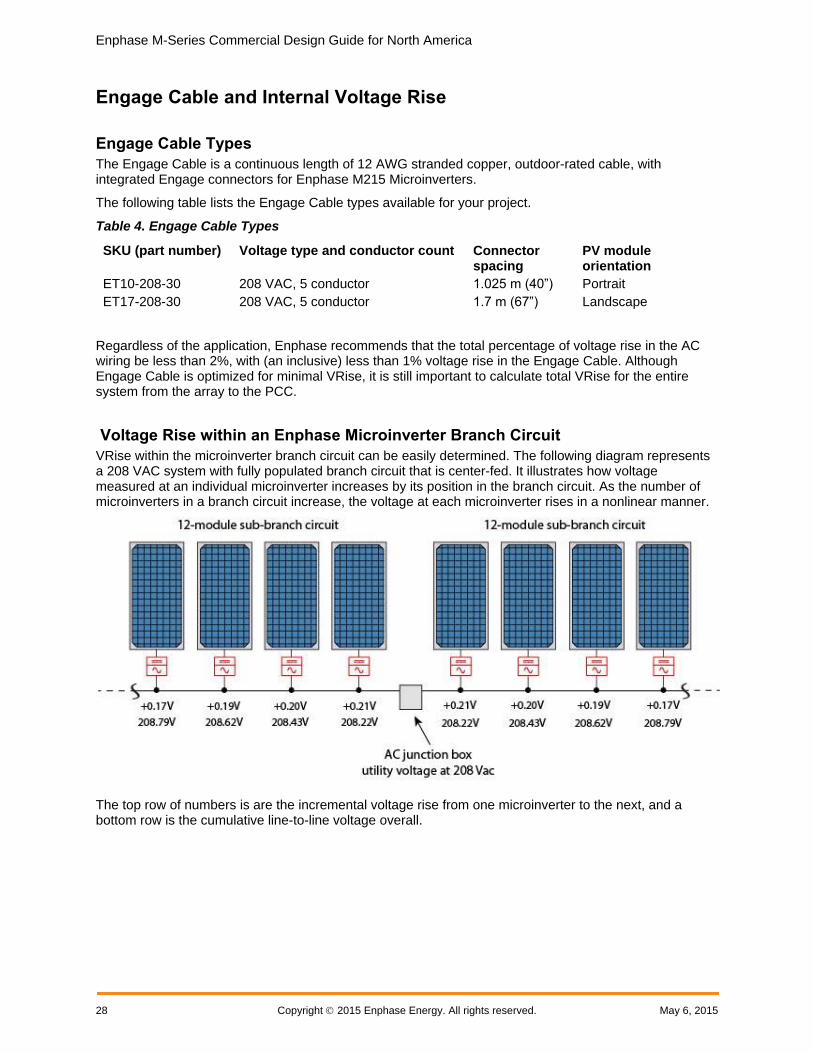
Voltage Rise within an Enphase Microinverter Branch Circuit
VRise within the microinverter branch circuit can be easily determined. The following diagram represents a 208 VAC system with fully populated branch circuit that is center-fed. It illustrates how voltage measured at an individual microinverter increases by its position in the branch circuit. As the number of microinverters in a branch circuit increase, the voltage at each microinverter rises in a nonlinear manner.
The top row of numbers is are the incremental voltage rise from one microinverter to the next, and a bottom row is the cumulative line-to-line voltage overall.

Enphase M-Series Commercial Design Guide for North America
May 6, 2015 Copyright 2015 Enphase Energy 29
The following graph illustrates how the number of microinverters connected to a portrait-oriented Engage Cable causes a nonlinear voltage rise when operating at 208 VAC.
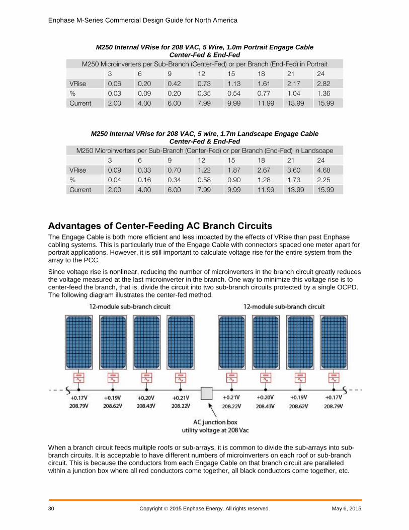
Microinverter Branch Circuit and 208 VAC Engage Cable Voltage Rise Tables
The following tables list 208 VAC Engage Cable internal voltage rise values by number of M215 or M250 Microinverters on a branch circuit. Refer to these tables when calculating voltage rise for your installation.
M215 Internal VRise for 208 VAC, 5 Wire, 1.0m Portrait Engage Cable Center-Fed & End-Fed
M215 Microinverters per Branch in Portrait
3 6 9 12 15 18 21 24
VRise 0.08 0.21 0.39 0.65 0.96 1.35 1.79 2.30
% 0.04 0.10 0.19 0.31 0.46 0.65 0.86 1.11
Current 1.79 3.58 5.37 7.16 8.95 10.74 12.53 14.32
M215 Internal VRise for 208 VAC, 5 wire, 1.7m Landscape Engage Cables Center-Fed & End-Fed
M215 Microinverters per Branch in Landscape
3 6 9 12 15 18 21 24
VRise 0.12 0.32 0.63 1.05 1.58 2.41 2.95 3.78
% 0.06 0.16 0.30 0.51 0.76 1.16 1.42 1.82
Current 1.79 3.58 5.37 7.16 8.95 10.74 12.53 14.32
0
0.5
1
1.5
2
2.5
3 6 9 12 15 18 21 24
Voltage
Microinverter Position in Branch
Internal VRise for 208 VAC1.0 m Portrait Engage Cables & M215s
Enphase M-Series Commercial Design Guide for North America
30 Copyright 2015 Enphase Energy. All rights reserved. May 6, 2015
M250 Internal VRise for 208 VAC, 5 Wire, 1.0m Portrait Engage Cable Center-Fed & End-Fed
M250 Microinverters per Sub-Branch (Center-Fed) or per Branch (End-Fed) in Portrait
3 6 9 12 15 18 21 24
VRise 0.06 0.20 0.42 0.73 1.13 1.61 2.17 2.82
% 0.03 0.09 0.20 0.35 0.54 0.77 1.04 1.36
Current 2.00 4.00 6.00 7.99 9.99 11.99 13.99 15.99
M250 Internal VRise for 208 VAC, 5 wire, 1.7m Landscape Engage Cable Center-Fed & End-Fed
M250 Microinverters per Sub-Branch (Center-Fed) or per Branch (End-Fed) in Landscape
3 6 9 12 15 18 21 24
VRise 0.09 0.33 0.70 1.22 1.87 2.67 3.60 4.68
% 0.04 0.16 0.34 0.58 0.90 1.28 1.73 2.25
Current 2.00 4.00 6.00 7.99 9.99 11.99 13.99 15.99
Advantages of Center-Feeding AC Branch Circuits The Engage Cable is both more efficient and less impacted by the effects of VRise than past Enphase cabling systems. This is particularly true of the Engage Cable with connectors spaced one meter apart for portrait applications. However, it is still important to calculate voltage rise for the entire system from the array to the PCC.
Since voltage rise is nonlinear, reducing the number of microinverters in the branch circuit greatly reduces the voltage measured at the last microinverter in the branch. One way to minimize this voltage rise is to center-feed the branch, that is, divide the circuit into two sub-branch circuits protected by a single OCPD. The following diagram illustrates the center-fed method.
When a branch circuit feeds multiple roofs or sub-arrays, it is common to divide the sub-arrays into sub-branch circuits. It is acceptable to have different numbers of microinverters on each roof or sub-branch circuit. This is because the conductors from each Engage Cable on that branch circuit are paralleled within a junction box where all red conductors come together, all black conductors come together, etc.

Enphase M-Series Commercial Design Guide for North America
May 6, 2015 Copyright 2015 Enphase Energy 31
Conductor Lengths for Wire Sections The following tables list the maximum conductor lengths from the AC junction box back to the main service panel for maintaining a 1% voltage rise. Use these tables to determine maximum conductor lengths for the wire sections in your installation.
M215 External Branch (Home Run) Wiring Maximum Distance to Maintain 1% VRise for 208 VAC Three-Phase
M215 Microinverters per Branch for 208 VAC Three-Phase
3 6 9 12 15 18 21 24 25
AWG Maximum One-Way Wire Length (in Feet)
to Maintain 1% VRise
#12 335 168 112 83.8 67 56 48 42 39
#10 559 279 186 140 112 93 80 70 64
#8 860 430 287 215 172 143 123 107 99
#6 1369 684 456 342 274 228 196 171 158
#4 2164 1082 721 541 433 361 309 270 250
M250 External Branch (Home Run) Wiring Maximum Distance to Maintain 1% VRise for 208 VAC Three-Phase
M250 Microinverters per Branch for 208 VAC Three-Phase
AWG
3 6 9 12 15 18 21 24
Maximum One-Way Wire Length (in Feet) to Maintain 1% VRise
#12 293 147 98 73 59 49 42 37
#10 501 250 167 125 100 83 72 63
#8 770 385 257 193 154 128 110 96
#6 1226 613 409 307 245 204 175 153
#4 1938 969 646 485 388 323 277 242
Voltage Rise Formula for a Three-Phase 208 VAC Installation All resistances of the system components are in series, and are cumulative. Since the same current is flowing through each resistance, the total VRise is simply the total current times the total resistance.
The VRise percentage for an Enphase Microinverter system is:
% of Total VRise = % VRise Section 1 + % VRise Section 2 + % VRise Section 3
In a 208 VAC, three-phase system, use only the one-way wire length for resistance in the provided formula. While this calculation is not commonly used, it is a simple and accurate calculation of voltage rise in an Enphase Microinverter system.
Enphase M-Series Commercial Design Guide for North America
32 Copyright 2015 Enphase Energy. All rights reserved. May 6, 2015
VRise of Section= (Watts/microinverter) × (number of microinverters/branch circuit) × (Ω/ft) × (1-way wire length) ÷ 208 Volts
%VRise = VRise÷ 208 Volts
Calculating Total VRise for M215 Three-Phase 208 VAC Installations This example calculates voltage rise for a system with 208 VAC three-phase service using 72 M215 Microinverters. The system has three fully-populated branch circuits of 24 M215 Microinverters mounted in portrait orientation.
For fully-loaded branch circuits with 208 VAC, Enphase recommends that you center-feed the circuit to minimize voltage rise. A center-fed branch of 24 microinverters has 12 microinverters on one sub-branch circuit and 12 on the other sub-branch.
The M215 Microinverter produces power on two legs, and the phases are balanced by the physical internal rotation of the phase cables inside the Engage Cable.
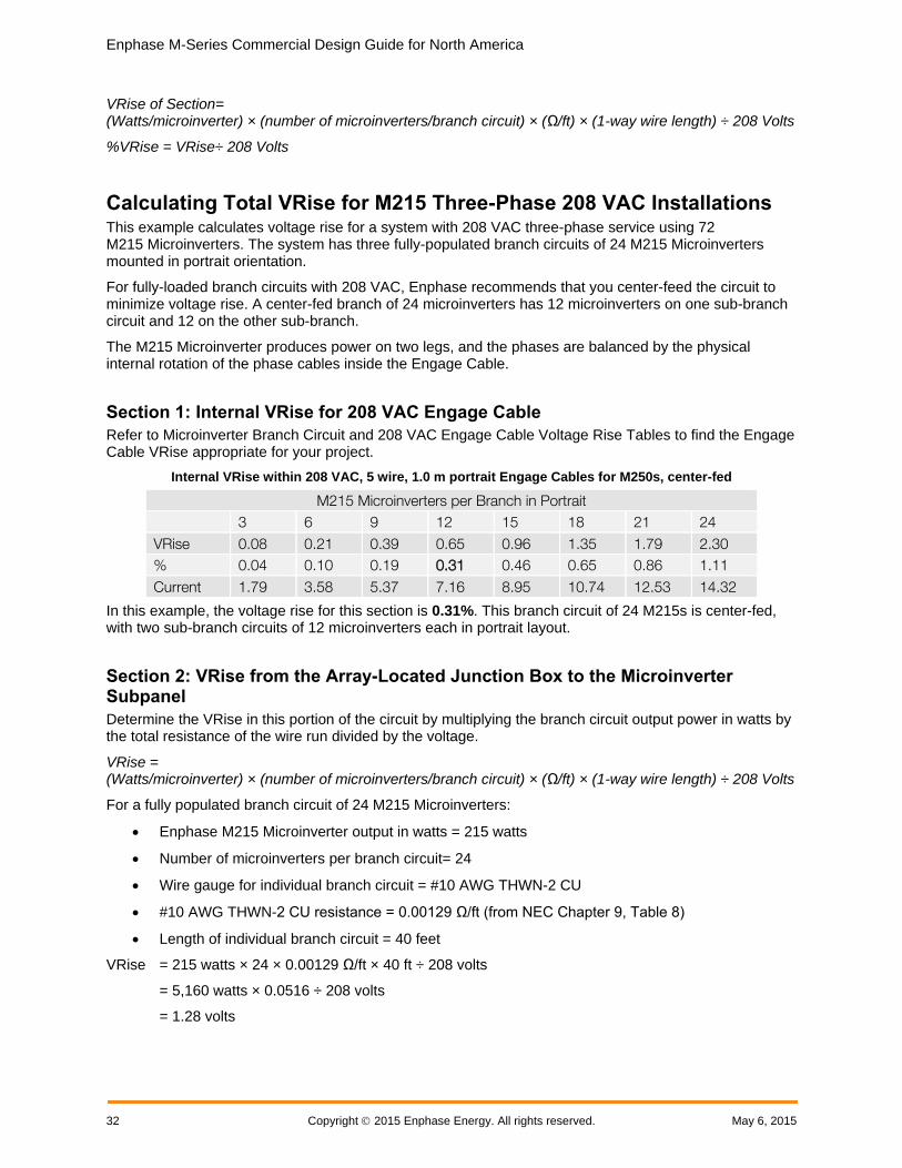
Section 1: Internal VRise for 208 VAC Engage Cable
Refer to Microinverter Branch Circuit and 208 VAC Engage Cable Voltage Rise Tables to find the Engage Cable VRise appropriate for your project.
Internal VRise within 208 VAC, 5 wire, 1.0 m portrait Engage Cables for M250s, center-fed
M215 Microinverters per Branch in Portrait
3 6 9 12 15 18 21 24
VRise 0.08 0.21 0.39 0.65 0.96 1.35 1.79 2.30
% 0.04 0.10 0.19 0.31 0.46 0.65 0.86 1.11
Current 1.79 3.58 5.37 7.16 8.95 10.74 12.53 14.32
In this example, the voltage rise for this section is 0.31%. This branch circuit of 24 M215s is center-fed, with two sub-branch circuits of 12 microinverters each in portrait layout.
Section 2: VRise from the Array-Located Junction Box to the Microinverter Subpanel
Determine the VRise in this portion of the circuit by multiplying the branch circuit output power in watts by the total resistance of the wire run divided by the voltage.
VRise = (Watts/microinverter) × (number of microinverters/branch circuit) × (Ω/ft) × (1-way wire length) ÷ 208 Volts
For a fully populated branch circuit of 24 M215 Microinverters:
Enphase M215 Microinverter output in watts = 215 watts
Number of microinverters per branch circuit= 24
Wire gauge for individual branch circuit = #10 AWG THWN-2 CU
#10 AWG THWN-2 CU resistance = 0.00129 Ω/ft (from NEC Chapter 9, Table 8)
Length of individual branch circuit = 40 feet
VRise = 215 watts × 24 × 0.00129 Ω/ft × 40 ft ÷ 208 volts
= 5,160 watts × 0.0516 ÷ 208 volts
= 1.28 volts

Enphase M-Series Commercial Design Guide for North America
May 6, 2015 Copyright 2015 Enphase Energy 33
%VRise = 1.28 volts ÷ 208 volts
= 0.62%
The voltage rise from the junction box to the microinverter subpanel is 0.62%.
Section 3: VRise from the Microinverter Subpanel to the Main Service Meter (PCC)
Determine the VRise in this portion of the circuit by multiplying the total microinverter subpanel output power in watts by the total resistance of the wire run divided by the voltage. The phases are balanced by the physical internal rotation of the phases inside the Engage Cable.
VRise = (Watts/microinverter) × (number of microinverters/branch circuit) × (Ω/ft) × (1-way wire length) ÷ 208 Volts
The following calculations are for three fully populated branch circuits of 24 M215 Microinverters, with two sub-branch circuits of 12 microinverters each, in portrait, for a total of 72 microinverters.
M215 Microinverter output in watts = 215 watts
Number of M215 Microinverters per microinverter subpanel = 72
Wire gauge for the microinverter subpanel feed = #2 AWG THWN-2 CU
#2 AWG THWN-2 CU resistance = 0.000201 Ω/ft (from NEC Chapter 9, Table 8)
Length of microinverter subpanel feed = 80 feet
VRise = 215 watts × 72 × 0.000201 Ω/ft × 80 ft ÷ 208 volts
= 15,480 watts × 0.01608 Ω ÷ 208 volts
= 1.20 volts
%VRise = 1.20 volts ÷ 208 volts
= 0.58%
The voltage rise from the microinverter subpanel to the main service meter is 0.58%.
M215 Summary of Calculations for Three-Phase 208 VAC Applications
With the utility operating at the upper limit of their allowable tolerance (+5%) and the microinverters having a measurement accuracy of 2.5%, the result is a voltage rise budget of 4.88 volts (2.25%) for all wiring to the PCC. The calculated VRise for all three portions of the system must be 4.88 volts or less.
For systems with long branch-circuit runs and/or long runs from the inverter subpanel to the main service panel or PCC, it is best to make the VRise in the Engage Cable as small as possible. However, after accounting for additional losses within connections, terminals, circuit breakers, and unexpected increases in wire length, Enphase recommends that the total system voltage rise to be less than 2%.
Voltage rise from the microinverters to the AC junction box = 0.31%
Voltage rise from the AC junction box to the microinverter subpanel = 0.62%
Voltage rise from the microinverter subpanel to the main service meter (PCC)
= 0.58%
Total system voltage rise for all three wiring sections = 1.51%
In this example, we were able keep the VRise to less than 2% by center-feeding the circuit to create two sub-branch circuits at the array.

Enphase M-Series Commercial Design Guide for North America
34 Copyright 2015 Enphase Energy. All rights reserved. May 6, 2015
Calculating Total VRise for M250 Three-Phase 208 VAC Installations This example calculates voltage rise for a system with three-phase 208 VAC service using 72 M250 Microinverters with three fully-populated branch circuits of 24 M250 Microinverters mounted in portrait orientation.
For fully loaded branch circuits with 208 VAC, Enphase recommends that you center-feed the circuit to minimize voltage rise. A center-fed branch of 24 microinverters has 12 microinverters on one sub-branch circuit and 12 on the other.
The M250 Microinverter produces power on two legs, and the phases are balanced by the physical internal rotation of the phase cables inside the Engage Cable
Section 1: Internal VRise 208 VAC Engage Cable
Refer to Microinverter Branch Circuit and 208 VAC Engage Cable Voltage Rise Tables to find the Engage Cable VRise appropriate for your project.
Internal VRise within 208 VAC, 5 wire, 1.0m portrait Engage Cables for M250s, center-fed
M250 Microinverters per Sub-Branch (Two Balanced Sub-Branches) in Portrait
3 6 9 12
VRise 0.06 0.20 0.42 0.73
% 0.03 0.09 0.20 0.35
Current 2.00 4.00 6.00 7.99
In this example, the voltage rise for this section is 0.35%. This branch circuit of 24 M250s is center-fed, with two sub-branch circuits of 12 microinverters each in portrait layout.
Section 2: VRise from the AC junction box to the Microinverter Subpanel
Determine the VRise in this portion of the circuit by multiplying the branch circuit output power in watts by the total resistance of the wire run divided by the voltage.
VRise = (Watts/microinverter) × (number of microinverters/branch circuit) × (Ω/ft) × (1-way wire length) ÷ 208 Volts
The following example is for a fully populated branch circuit of 24 M250 Microinverters.
M250 rated AC output in watts = 240 watts
Number of microinverters per branch circuit = 24
Wire gauge for individual branch circuit = #10 AWG THWN-2 CU
#10 AWG THWN-2 CU resistance = 0.00129 Ω/ft (from NEC Chapter 9, Table 8)
Length of individual branch circuit = 40 feet
VRise = 240 watts × 24 × 0.00129 Ω/ft × 40 ft ÷ 208 volts
= 5,760 watts × 0.0516 ÷ 208 volts
= 1.42 volts
%VRise = 1.42 volts ÷ 208 volts
= 0.69%
The voltage rise from the junction box to the microinverter subpanel is 0.69%.

Enphase M-Series Commercial Design Guide for North America
May 6, 2015 Copyright 2015 Enphase Energy 35
Section 3: VRise from the Microinverter Subpanel to the Main Service Meter (PCC)
Determine the VRise in this portion of the circuit by multiplying the total microinverter subpanel output power in watts by the total resistance of the wire run divided by the voltage. The phases are balanced by the physical internal rotation of the phases inside the Engage Cable.
The following calculations are for three fully populated branch circuits of 24 M250 Microinverters, with two sub-branch circuits of 12 microinverters each, in portrait, for a total of 72 microinverters.
M250 rated AC output in watts = 240 watts
Number of Microinverters per microinverter subpanel = 72
Wire gauge for the microinverter subpanel feed = #2 AWG THWN-2 CU
#2 AWG THWN-2 CU resistance = 0.000201 Ω/ft (from NEC Chapter 9, Table 8)
Length of microinverter subpanel feed = 80 feet
VRise = 240 watts × 72 × 0.000201 Ω/ft × 80 ft ÷ 208 volts
= 17,280 watts × 0.01608 Ω ÷ 208 volts
= 1.34 volts
%VRise = 1.34 volts ÷ 208 volts
= 0.64%
The voltage rise from the microinverter subpanel to the main service meter is 0.64%.
Summary of Wire Section Calculations for Three-Phase 208 VAC Applications
With the utility operating at the upper limit of their allowable tolerance (+5%) and the microinverters having a measurement accuracy of 2.5%, the result is a voltage rise budget of 4.88 volts (2.25%) for all wiring to the PCC. The calculated VRise for all three portions of the system must be 4.88 volts or less.
For systems with long-branch circuit runs and/or long runs from the inverter subpanel to the main service panel or PCC, it is best to make the VRise in the Engage Cable as small as possible. However, after accounting for additional losses within connections, terminals, circuit breakers, and unexpected increases in wire length, Enphase recommends calculating a total system voltage rise of less than 2%.
Section 1: Voltage rise in Engage Cable from the microinverters to the AC junction box = 0.35%
Section 2: Voltage rise from the AC junction box to the microinverter subpanel = 0.69%
Section 3: Voltage rise from the microinverter subpanel to the main service meter (PCC) = 0.64%
Total system voltage rise for all three wire sections = 1.68%
In this example, we were able keep the VRise to less than 2% by center-feeding the circuit to create two sub-branch circuits at the array.
Conclusion Center feeding is a great way to decrease costs, improve production, and increase system reliability.
Center-feeding each branch circuit in an Enphase Microinverter System is essential, both for optimal microinverter operation and to minimize wire costs for the installer. Follow the guidelines and calculations in this document to help to minimize voltage rise or voltage drop issues with your installation.

Enphase M-Series Commercial Design Guide for North America
36 Copyright 2015 Enphase Energy. All rights reserved. May 6, 2015
Section 3: Grounding Considerations for Enphase M215 and M250 Installations GFP within the M250 and M215 Eliminates the Need for a GEC
Enphase fourth generation integrated ground (IG) microinverters (M250-60-2LL-S22, S23, and S24 and M215-60-2LL-S22-IG, S23-IG, and S24-IG) do not require a Grounding Electrode Conductor (GEC). The DC circuit within the microinverter is isolated and insulated from ground and ground fault protection (GFP) is integrated into the microinverter. As a result, these microinverters take less time to install than other microinverters, save money, and increase safety.
Original M215 Models and Grounding
If you are installing the original M215 (M215-60-2LL-S22, S23, or S24), a GEC or other compliant grounding method is required.
TIP: If installing a mix of IG (Integrated Ground) and non-IG microinverters, install the non-IG microinverters closer (electrically) to the junction box to minimize GEC use.

Enphase M-Series Commercial Design Guide for North America
May 6, 2015 Copyright 2015 Enphase Energy 37
Section 4: Commissioning for a Multi-Envoy Site Proper site commissioning is critical to the success of the project. Install the Envoy and connect it to the Internet at least one hour before you complete your solar installation and before the microinverters are producing power. If you install multiple Enphase systems in the same neighborhood or on the same utility transformer, commission only one system at a time.
Commissioning Steps In an Enphase system, the Envoy database must be properly provisioned with the serial numbers of the microinverters that it will be monitoring. Take special care to ensure that each Envoy is provisioned with only the serial numbers of the microinverters in its communication domain.
While you can still provision the communication domain from the Envoy Device Scan, you can now do this more easily using the Enphase Array Gun and Installer Toolkit App.
Provisioning the Envoy with the Installer Toolkit App
The Enphase Installer Toolkit is an iOS app that provides installers with onsite system configuration capabilities, eliminating the need for a laptop and improving installation efficiency. You can use the app to:
Connect to the Envoy over a wireless network for faster system setup and verification.
View and email a summary report that confirms a successful application of a grid profile.
Combine with a Bluetooth-enabled scanner to scan microinverter serial numbers and sync system information with Enlighten monitoring software.
What follows are high-level steps to commission one Envoy in a multi-Envoy environment. Refer to the Enphase Installer Toolkit Operation Manual for detailed instructions.
1. Download and install the Installer Toolkit app. In the iTunes app store, search for Enphase.
2. Set up the scanner and pair it with your iOS device. For instructions, refer to the manufacturer’s Quick Start Guide.
3. Launch the Toolkit App and log in to Enlighten.
4. Use the on-site wireless router to connect to the same LAN as the Envoy. Or, create a temporary LAN using a portable router such as the TP-LINK TL-MR3040
5. The Installer Toolkit scanning tool screen displays the names of the arrays and the number of microinverters associated with each array.
6. Connect to Envoy that you want to provision. The Installer Toolkit automatically attempts to connect to the Envoy.
7. Enter or confirm the number of microinverters that you expect to report to this Envoy. If you have already used the Installer Toolkit scanning tool to record the microinverters in the array(s) associated with this Envoy, the total number scanned displays.
8. For multiple Envoys, select or add an Envoy before scanning microinverters. To select or add an Envoy by scanning the bar code, tap [>] (to the right of the word “Envoy”), then follow the on-screen instructions.
9. Tap Scan at the bottom of the System Overview screen to add an array.
10. Tap the Name field and enter the array name. Enter other array details as needed.
11. Save the information.
12. Tap the array name to start the microinverter scan.

Enphase M-Series Commercial Design Guide for North America
38 Copyright 2015 Enphase Energy. All rights reserved. May 6, 2015
13. Tap the module location where you want to start scanning.
14. Scan the bar code on your first microinverter.
15. Repeat the steps 13–14 until you have completed the scan, or turn on Auto-Scan.
Provisioning the Envoy with the Device Scan
Follow these steps to commission one Envoy in a multi-Envoy environment:
1. Plug in the Envoy to a standard 120VAC receptacle.
2. Connect the Local Area Network to the Envoy. Verify that the green link light on the back of the Envoy displays.
3. The Envoy displays “+Web” after four or five minutes.
4. Once the Envoy has connected to the Web, it may automatically update its software. Do not unplug the Envoy during this time. The Envoy displays “Upgrading… Do Not Unplug.” The software update may last for 15 minutes or longer, depending on the connection speed and software version. The Envoy displays “-Web” for about two minutes after the new software has been updated, but quickly returns to “+Web”.
5. Ensure that the Envoy displays a communication level of at least three bars. If it does not, troubleshoot the system. Refer to the Enphase Troubleshooting Guide at http://www.enphase.com before installing any additional system components at the site.
6. Upon startup, the Envoy begins an eight-hour device scan for new devices. If the Envoy detects microinverters before the solar array is powered on, then those microinverters have been "poached" from another system. Use a laptop to access the Envoy Device Conditions and Controls menu and delete those microinverters, or contact [email protected].
7. Once the installation is complete and all electrical panels and junction boxes have been properly closed and covered, turn on the photovoltaic system that is associated with this Envoy. The Envoy now begins to populate its database with the microinverters on site. This generally takes about 20 minutes, but can take longer. This will not work at night as the microinverters operate only during daylight hours as they are powered by DC solar power.
8. Once the Envoy has populated its database with all of the microinverters at the site, press and hold down the menu button on the right side of the Envoy until the display reads “Disable New Device Scan.” After the device scan disables, you can commission another Envoy at the site.
9. As an additional precaution, you may send a request to [email protected] to “Inhibit Device Scanning” at the site so that no further device scans can be run by the site owner.
10. Once the scan is complete, request that the microinverters be upgraded to the latest software version. To request an upgrade, contact [email protected].

Enphase M-Series Commercial Design Guide for North America
May 6, 2015 Copyright 2015 Enphase Energy 39
Section 5: Networking and PLC Considerations for Commercial Projects This section addresses networking and power line communications (PLC) for commercial systems, with an emphasis on how to configure commercial installations for decades of trouble-free operation and monitoring.
PLC Considerations Enphase Microinverters communicate with the Envoy through power line communications. Enphase equipment sends and receives signals in the 100–150 kHz band over the same conductors that carry AC system power. With all Enphase installations, good communication between the array and the Envoy is necessary for system monitoring and maintenance.
Besides communicating with microinverters via power lines on the premises, the Envoy also communicates with Enlighten via an Ethernet cable connected to the broadband router on site. The Envoy is like another computer at the premises, connecting through a standard Ethernet LAN (Local Area Network) cable and using standard TCP/IP protocols.
Power line communications are very robust and reliable in a commercial Enphase system because array-located transformers or filters generally provide a clean communications environment.
LAN/WAN Guidelines for Envoy Communication This section covers networking basics and troubleshooting.
DHCP and Self Assigned IP Address (169.254.x.x)
When the Envoy first boots up, it performs a Dynamic Host Configuration Protocol (DHCP) broadcast to request an IP address from a DHCP source. A DHCP source is usually a server or computer, but almost all consumer-grade broadband routers also provide DHCP services as well. The broadband router is the usual source of IP addresses for network hosts like computers, laptops, and the Envoy.
If the Envoy LCD window displays an IP address beginning with 169.254, the Envoy was unable to receive an IP address from a DHCP source and assigned this address to itself. To troubleshoot, first check the Ethernet cabling connection, then check that the router provides DHCP services.
DHCP versus Static IP Addressing
If the site owner prefers not to use DHCP, you can set up the Envoy to use a static IP address as follows.
1. Use the Envoy web interface and navigate to the Administration page.
2. Log in with the user name, admin, and password, admin.
3. Click the Network Connectivity menu item. This allows you to see if the Envoy is using DHCP or Static-IP, and allows you to change this setting if needed.
4. Click Check Network Connectivity to view the Envoy connections.
For more information on how to use the Envoy Interface, refer to the Envoy Communications Gateway Installation and Operation Manual at http://www.enphase.com.
WARNING: Do not change the Envoy DHCP setting to a static IP address unless you also reserve the same IP address on your broadband router. See the section on DHCP Reservations in the router setup manual. Failure to reserve the static IP address on the router results in duplicate IP addresses and intermittent Internet connection for the Envoy.
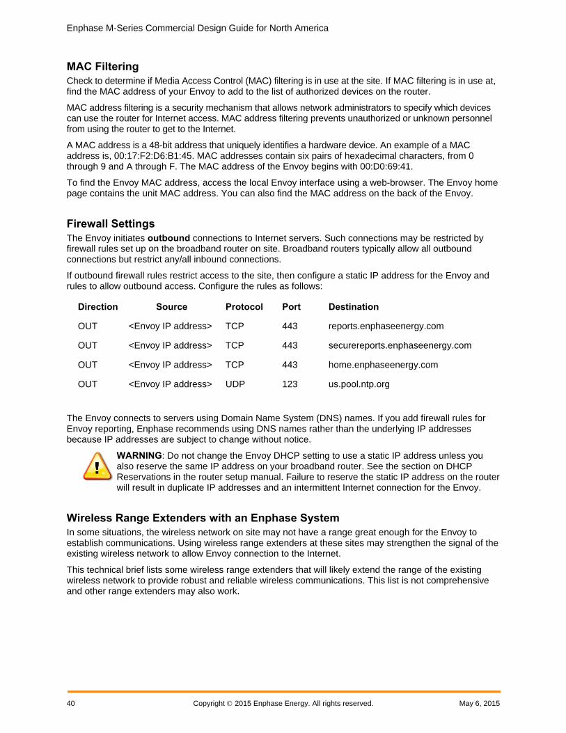
Enphase M-Series Commercial Design Guide for North America
40 Copyright 2015 Enphase Energy. All rights reserved. May 6, 2015
MAC Filtering
Check to determine if Media Access Control (MAC) filtering is in use at the site. If MAC filtering is in use at, find the MAC address of your Envoy to add to the list of authorized devices on the router.
MAC address filtering is a security mechanism that allows network administrators to specify which devices can use the router for Internet access. MAC address filtering prevents unauthorized or unknown personnel from using the router to get to the Internet.
A MAC address is a 48-bit address that uniquely identifies a hardware device. An example of a MAC address is, 00:17:F2:D6:B1:45. MAC addresses contain six pairs of hexadecimal characters, from 0 through 9 and A through F. The MAC address of the Envoy begins with 00:D0:69:41.
To find the Envoy MAC address, access the local Envoy interface using a web-browser. The Envoy home page contains the unit MAC address. You can also find the MAC address on the back of the Envoy.
Firewall Settings
The Envoy initiates outbound connections to Internet servers. Such connections may be restricted by firewall rules set up on the broadband router on site. Broadband routers typically allow all outbound connections but restrict any/all inbound connections.
If outbound firewall rules restrict access to the site, then configure a static IP address for the Envoy and rules to allow outbound access. Configure the rules as follows:
The Envoy connects to servers using Domain Name System (DNS) names. If you add firewall rules for Envoy reporting, Enphase recommends using DNS names rather than the underlying IP addresses because IP addresses are subject to change without notice.
WARNING: Do not change the Envoy DHCP setting to use a static IP address unless you also reserve the same IP address on your broadband router. See the section on DHCP Reservations in the router setup manual. Failure to reserve the static IP address on the router will result in duplicate IP addresses and an intermittent Internet connection for the Envoy.
Wireless Range Extenders with an Enphase System
In some situations, the wireless network on site may not have a range great enough for the Envoy to establish communications. Using wireless range extenders at these sites may strengthen the signal of the existing wireless network to allow Envoy connection to the Internet.
This technical brief lists some wireless range extenders that will likely extend the range of the existing wireless network to provide robust and reliable wireless communications. This list is not comprehensive and other range extenders may also work.
Direction Source Protocol Port Destination
OUT <Envoy IP address> TCP 443 reports.enphaseenergy.com
OUT <Envoy IP address> TCP 443 securereports.enphaseenergy.com
OUT <Envoy IP address> TCP 443 home.enphaseenergy.com
OUT <Envoy IP address> UDP 123 us.pool.ntp.org

Enphase M-Series Commercial Design Guide for North America
May 6, 2015 Copyright 2015 Enphase Energy 41
The Envoy with Wireless Adapter
The Envoy Communications Gateway is available with a wireless adapter for sites using a wireless router.
The Enphase Wireless Adapter (Wi-Fi USB stick), included with the Envoy model ENV-120-02, allows the Envoy to transmit Enphase Microinverter System data through the on-site wireless network to the Enlighten Monitoring platform.
Using the wireless adapter simplifies Envoy installation and reduces system commissioning time.
With the Enphase wireless adapter, you can connect the Envoy to the Internet in one of two ways.
• Use the Wi-Fi WPS button on the wireless router.
• Configure the Envoy manually using the Envoy local interface.
Refer to the Envoy Installation and Operations Manual for complete and detailed installation steps.
Some installation sites may require that you extend the range of the existing Wi-Fi network so that the Envoy with the wireless adapter can connect to the Internet.
Envoy-Compatible Wireless Range Extenders
Manufacturer Model Use WPS
Button to Connect to Envoy?
D-Link DAP-1320 Yes
Comments
Easy configuration, took one minute.
This model has a WPS button.
Comes with a card listing the default network name: dlink-3D92, and password.
Also connects through the Envoy local interface.
Indoor rated.
www.dlink.com/us/en
Manufacturer Model Use WPS Button for Envoy Connection?
NETGEAR WN1000-RP (N150) Yes
Comments
Easy to install and connect to routers.
This model has a WPS button. Press the WPS button on both the extender and router for five seconds to connect and get a signal within one minute.
Provides a network connection named after the extended network, but with a suffix of -ext added.
After connecting this device to the existing wireless network, press the WPS button again to connect the Envoy to the range extender. Otherwise, the password to connect to the extended network is, by default, the password for the original network.
www.netgear.com
Manufacturer Model Use WPS Button for Envoy Connection?

Enphase M-Series Commercial Design Guide for North America
42 Copyright 2015 Enphase Energy. All rights reserved. May 6, 2015
Edimax EW-7438RPn (N300) No
Comments
Easy to install and connect to routers.
This model has a WPS button. The WPS button connects range extender to the existing wireless network, but does not connect the Envoy to the wireless network.
Has the highest speed and longest range of the models tested.
Extends an existing Wi-Fi network, and provides a hard-wired LAN connection to one device.
By default, the extended network name is the existing wireless name plus a suffix with six numbers and letters after.
Requires that you access the local Envoy interface to enable wireless. To connect an Envoy to this extended network, use a computer to access the Envoy local interface. Connect the Envoy per the Envoy Installation Manual, select the network, and then enter the network password for the wireless network.
www.edimax.com
Manufacturer Model Use WPS Button for Envoy Connection?
Amped Wireless REC10 Yes
Comments
Increases wireless signal range by up to 6,500 sq ft.
This model has a WPS button.
Extends an existing Wi-Fi network, and provides a hard-wired LAN connection to one device.
Signal is not as strong at longer distances.
After connecting this device to the existing wireless network, press the WPS button again to connect the Envoy to the range extender. Otherwise, the password to connect to the extended network is, by default, the password for the original network.
www.ampedwireless.com
The Envoy Installation and Operations Manual contains installation and troubleshooting procedures to help you connect the Envoy to the Internet. Review the instructions in the manual before you set up the Envoy and the wireless adapter.
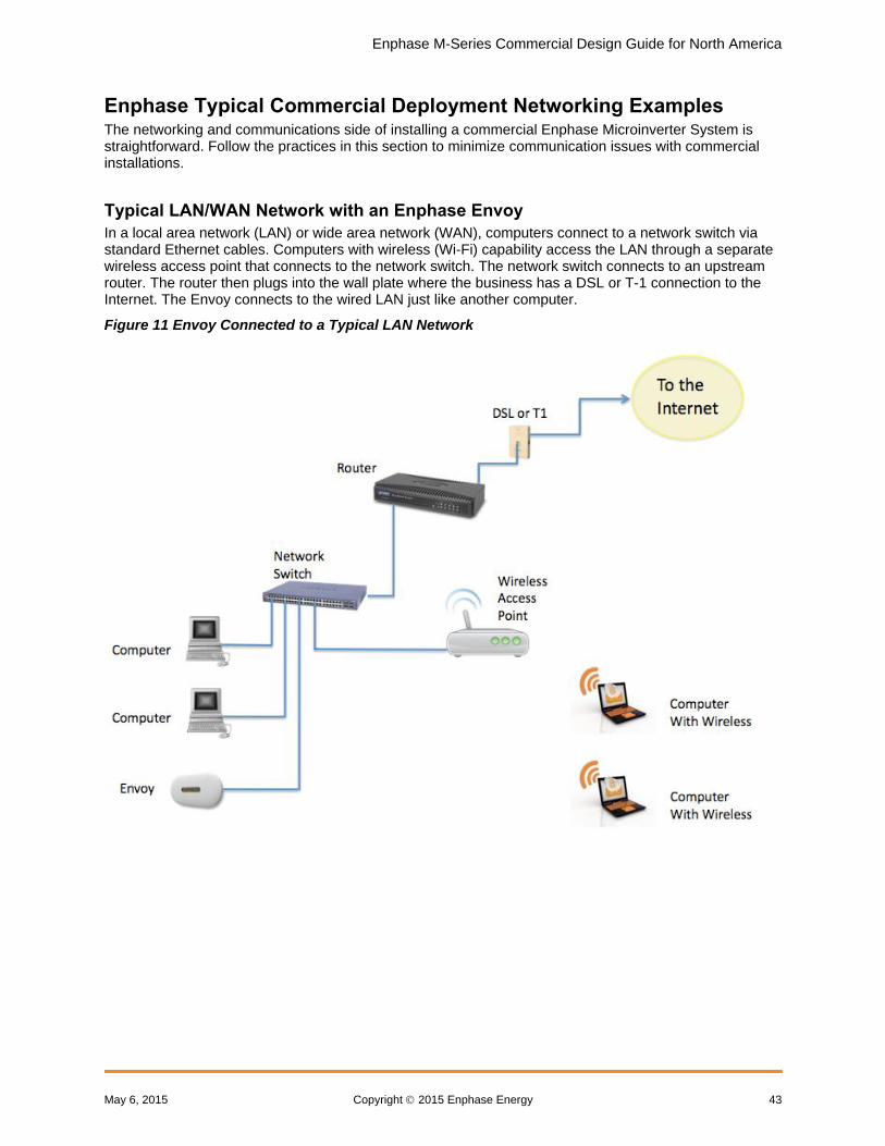
Enphase M-Series Commercial Design Guide for North America
May 6, 2015 Copyright 2015 Enphase Energy 43
Enphase Typical Commercial Deployment Networking Examples The networking and communications side of installing a commercial Enphase Microinverter System is straightforward. Follow the practices in this section to minimize communication issues with commercial installations.
Typical LAN/WAN Network with an Enphase Envoy
In a local area network (LAN) or wide area network (WAN), computers connect to a network switch via standard Ethernet cables. Computers with wireless (Wi-Fi) capability access the LAN through a separate wireless access point that connects to the network switch. The network switch connects to an upstream router. The router then plugs into the wall plate where the business has a DSL or T-1 connection to the Internet. The Envoy connects to the wired LAN just like another computer.
Figure 11 Envoy Connected to a Typical LAN Network
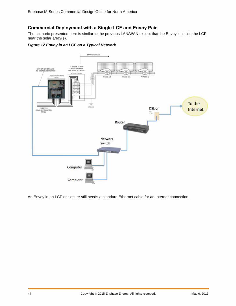
Enphase M-Series Commercial Design Guide for North America
44 Copyright 2015 Enphase Energy. All rights reserved. May 6, 2015
Commercial Deployment with a Single LCF and Envoy Pair
The scenario presented here is similar to the previous LAN/WAN except that the Envoy is inside the LCF near the solar array(s).
Figure 12 Envoy in an LCF on a Typical Network
An Envoy in an LCF enclosure still needs a standard Ethernet cable for an Internet connection.

Enphase M-Series Commercial Design Guide for North America
May 6, 2015 Copyright 2015 Enphase Energy 45
Typical Commercial Deployment with Multiple LCFs and Envoys
This example shows a commercial deployment with multiple LCFs, each with a built-in Envoy. Each Envoy communicates with its own domain of microinverters through the power lines. The diagram below shows two LCFs, each with its own domain of microinverters and attached photovoltaic (PV) modules.
Figure 13 Multiple LCFs in a Network
This model scales as large as needed. For each additional communications domain, add another LCF and Envoy pair. The filtering mechanism of the LCF, the power line communications from one communications domain is isolated and separated from any others.

Enphase M-Series Commercial Design Guide for North America
46 Copyright 2015 Enphase Energy. All rights reserved. May 6, 2015
Ethernet Network and Wireless LAN
In commercial deployments, you can install a wireless access point to provide Internet connectivity for one or more LCF and Envoy pairs.
On the network side, the wireless access point is hard-wired connection to an Internet switch or router. On the PV module side, connect a wireless bridge to the Envoy so that it can communicate across Wi-Fi services.
As shown in the diagram below, each Envoy requires its own wireless Ethernet bridge to pass data to the wireless access point.
Figure 14 Multiple LCFs with Wireless Ethernet Bridges
Wireless LAN Technologies
Consumer-grade Wi-Fi devices have varying ranges of operation. Not all Wi-Fi vendors specify the unobstructed distance for which their product provides wireless coverage.
Wireless specification 802.11g is the current standard, with 802.11n recently ratified. Check vendor specifications for claims of distance and coverage. Also factor in obstructions, such as buildings, walls, and such, for your site.
Wireless vendors include:
Linksys: http://home.cisco.com/en-us/wireless/linksys/
Netgear: http://www.netgear.com
Ubiquity Networks: http://www.ubnt.com/
Meraki: http://meraki.com/

Enphase M-Series Commercial Design Guide for North America
May 6, 2015 Copyright 2015 Enphase Energy 47
Wireless Routers
Wi-Fi routers provide a wireless gateway to the Internet. Wireless vendors Linksys and Netgear produce reliable Wi-Fi routers. Most come with installation DVDs and software for easy setup, have excellent documentation, and come with phone/online technical support.
Wireless Ethernet Bridges
A wireless Ethernet bridge converts a wired Ethernet device for use on a wireless network. (Think of it as an external wireless network card). The Linksys WET610N and Netgear WNCE2001 are often recommended.
The Envoy has a USB port currently used for engineering diagnostics, and is not configured for Wi-Fi support. You can, however, power the Netgear WNCE2001 through the Envoy USB port. The Netgear WNCE2001 is about the size of a deck of cards, connects to the Envoy through an Ethernet cable, and is a lot less cumbersome than some other Ethernet (to Wi-Fi) bridges.
Wireless Hi-Gain Antenna Systems
Wireless Hi-Gain Antenna systems can be useful when the distance from the LCF to a wireless router is over 500 feet. Enphase recommends Ubiquity Networks directional Nanostation 2s. The system is made for outdoor use, with a variety of mounting brackets available. Configuration is done through a web interface and tools are available to verify signal strength between devices.
Figure 15 LCF with a Wireless Hi-Gain System

Enphase M-Series Commercial Design Guide for North America
48 Copyright 2015 Enphase Energy. All rights reserved. May 6, 2015
Wireless Mesh Network
A wireless mesh network is a communications network made up of multiple wireless bridges and antennas organized in a mesh topology. Apply this topology at sites with multiple buildings where cabling can be difficult to deploy. Ubiquity Networks makes a weatherproof Nanostation 2 with PicoStation M units. Meraki Networks also makes a weatherproof unit called the OD2, which is an Omni-directional Wi-Fi access point. The OD2 can to connect an LCF and transmit a signal to extend reach to other OD2 devices.
Figure 16 Typical Mesh Network Topology

Enphase M-Series Commercial Design Guide for North America
May 6, 2015 Copyright 2015 Enphase Energy 49
Appendix A: Lightning and Surge Suppression in Commercial Systems Although not common, the possibility of lightning strikes must be addressed. Following the guidelines in this Appendix helps minimize any lightning related issues with your commercial installation.
Enphase Microinverters, like all electrical components, can be damaged by lightning strikes or voltage surges from the electrical grid. For this reason, Enphase recommends that you protect your system with lightning and/or surge suppression devices. While lightning is not common in all regions, surges can occur anywhere on the electrical grid.
Enphase Microinverters have integral surge protection that is more robust than most string inverters. However, if the surge has sufficient energy, the protection built into the microinverter can be exceeded and the equipment may be damaged.
This section recommends some lightning protection and surge suppression devices, but there are a wide range of devices that can be installed with a wide range of warranties available from the equipment manufacturers. However, Enphase does not warrant or guarantee the performance of any of these products. In addition to having some level of surge suppression, it is important to have insurance that protects against lightning and electrical surges.
Lightning Protection A lightning arrestor is a device that diverts a portion of the energy from a lightning strike to earth, using a site grounding system. More advanced lightning protection systems also dissipates electrical charges from the building, lowering the chance of experiencing a lightning strike.
A lightning strike does not actually need to strike the equipment or building where a PV system is installed to cause damage. A strike on or near to the electric grid can induce voltage spikes that can damage equipment. Enphase Microinverters have integral surge protection that is more robust than most string inverters. However, if the surge has sufficient energy, the protection built into the microinverter can be exceeded, and the equipment may be damaged.
Surge Suppression Surge suppression devices protect site loads from lightning and electrical surges, and can be installed in parallel or in-line. A panel level surge suppressor interrupts the circuit and isolates equipment from the source of the surge.
A whole-house surge suppression system generally consists of in-line devices and surge suppressors. These systems are the most robust, but can be expensive and cost prohibitive.
Enphase Recommended Devices Enphase Microinverters have integral surge protection, greater than most traditional inverters. However, if the surge has sufficient energy, the protection built into the microinverter can be exceeded, and the equipment can be damaged.

Enphase M-Series Commercial Design Guide for North America
50 Copyright 2015 Enphase Energy. All rights reserved. May 6, 2015
Since the Enphase Limited Warranty does not cover “acts of God” such as lightning strikes, and since lightning strikes can occur anywhere, it is best practice to install surge protection as part of any solar installation. Enphase recommend the following protection devices. These have been tested to ensure that they do not interfere with Enphase power line communications, but most devices should work fine. Install per vendor instructions.
An inline surge protective device provides the greatest level of protection, but is often more expensive than a surge protective device that sits in parallel to the microinverter panel board and will likely filter the power line communications in a system.
If using an inline surge protective device, then the Envoy and microinverters must be located together on the load side of this device.
Single Phase AC Applications
Citel DS72-RS-120 surge protector; data sheet
Delta LA-302 lightning arrestor; website
Leviton 51110 or 51110-001; whole house surge protection panel; website
Midnight solar surge protection device MNSPD-300 or MNSPD-300FM (with flush mount box); website
Three-Phase AC Applications
Citel DS73-RS-G surge protector; data sheet
Delta LA-303 lightning arrestor; website

Enphase M-Series Commercial Design Guide for North America
May 6, 2015 Copyright 2015 Enphase Energy 51
Appendix B: Dropped Phase Hardware Solution For project success, you must consider phase imbalance when designing commercial PV systems using M215 or M250 Microinverters that interconnect to a three-phase service. This appendix provides details and recommends best practices for designing systems compatible with utility phase imbalance guidelines.
Dropped Phase Scenario The Enphase M215 or M250 Microinverter connects to two of the three available phases of a three-phase 208V WYE service. Three-phase 208VAC Engage Cable includes five conductors and is used for most commercial installations. Because Enphase Microinverters output onto two phases, three-phase cabling balances the phases by rotating conductor use from one microinverter to the next by alternating between phases (within the cabling) between each microinverter. For example, if the first microinverter (connector A) is connected to phases 1 and 2, then the second will be connected to 2 and 3, the third to 3 and 1, and the fourth to 1 and 2 once again. The pattern continues to repeat itself, modulo three, as shown in the following diagram.
If a grid failure occurs only on phase A, then one third of the microinverters connected exclusively to phases B and C will be unable to detect the failure. These microinverters may continue to export power on those phases, contributing to the phase imbalance present on the local grid node.
Dropped Phase Hardware Solution Enphase recommends the use of an overload relay system for loss of phase applications. An overload relay system consists of:
An overload relay that monitors the three line voltages and detects loss of phase
A contactor that opens all three lines of the circuit to disrupt the power flow
Ideally, an overload relay is mounted directly onto the contactor and forms one unit. If it is not possible to procure a combined unit, the contactor must be hardwired to the overload relay, and the overload relay must be powered by a dedicated breaker connected to grid power on the grid side of the dedicated PV portion of the system.
Install the combined relay-contactor system on the PV system side of the PCC and on the grid side of the LCF. For systems with no LCF, install the relay-contactor system on the grid side of the main PV load center, as shown in the following diagram.

Enphase M-Series Commercial Design Guide for North America
52 Copyright 2015 Enphase Energy. All rights reserved. May 6, 2015
For example, in a 10kW installation, we recommend a 40-50A, general use, IEC rated, 120V coil contactor, available from Allen-Bradley or equivalent. The voltage sensing relay part number is in the group 813S-xx. The contactor part number, also from Allen-Bradley (Rockwell Automation), is in the group 100-xxx.
Siemens, ABB and Square D are all examples of reputable manufacturers of overload relays and contactors.

Enphase M-Series Commercial Design Guide for North America
May 6, 2015 Copyright 2015 Enphase Energy 53
Appendix C: Fault Current Contribution in the M215 & M250 Microinverters Appendices C and D address two technical characteristics of power output in the Enphase Microinverter system, fault current contribution and total distortion: Utilities are interested in these characteristics because:
The total maximum fault current that a distributed energy resource (DER) contributes determines how robust the over-current protection device (OCPD) on the downstream (grid) side should be.
Total distortion indicates how closely the device output power signal adheres to an ideal sine wave.
Follow the guidelines in this Appendix to help minimize any loss of phase issues that might arise.
Fault Current Contribution This section is in response to inquiries received by Enphase about the relationship of fault current contributions to kilo-Ampere Interrupting Capacity (kAIC) ratings.
The fault current contribution of Enphase Microinverters is far less than the kAIC rating of any circuit breaker. Only circuit breakers, fuses, and some load-rated switches have AIC ratings. As a current source, a utility interactive inverter does not by itself, require an AIC rating.
Some utility electrical services requirements state that the short circuit current and OCPD shall be based on the type of service that is provided to the system (PCC). For instance, for residences, duplexes, and mobile homes supplied at 120/240 volts, one phase, three wire:
At 0–225A service ampacity, the short circuit current rating (SCCR) required is 10kA.
At 226–400A service ampacity, the SCCR required is 22kA.
Utilities are concerned with the kAIC rating of the main breaker for two reasons:
1. Will the breaker interrupt the current when a fault is present on the residential (load) side of the breaker?
2. Will the breaker interrupt the current supplied by the Distributed Generator (DG) when the short is located on the grid side? Is it possible for the DG to deliver more current than the circuit breaker can interrupt?
Calculating Fault Current Contribution from Enphase Microinverters
When calculating the fault current contribution from Enphase Microinverters, add up the fault current contribution from all microinverters. Compare this sum to the AIC rating of the main breaker.
For a M215 Microinverter on a 240V single-phase connection, the correct fault contribution value is 1.05 ARMS for 3 cycles.
In an installation with 120 microinverters and with a main breaker rated at 10kAIC, the fault current contribution from the microinverters is:
120 microinverters x 1.05 ARMS = 126 ARMs for three cycles
Since this value is only a small fraction of 10 kAIC, the 10 kAIC main breaker is sized correctly to interrupt any fault current contributed by the DG.

Enphase M-Series Commercial Design Guide for North America
54 Copyright 2015 Enphase Energy. All rights reserved. May 6, 2015
Likewise, the utility must insure that the fault current supplied from the utility is less than 10kA. The utility determines this based on several factors, including:
The full load amps of the transformer (Most important)
The transformer impedance
This information should be available from the nameplate rating of the utility transformer. From this information, you can determine the fault current available from the utility. For the previous example, the fault current should be less than 10 kAIC. For larger service ampacities, the rating should be higher.
In Understanding Fault Characteristics of Inverter-Based Distributed Energy Resources, a National Renewable Energy Laboratory study published in January 2010, Keller & Kroposki address fault current contributions of Distributed Energy Resources (DERs) and inverters in particular:
Inverters do not dynamically behave the same as synchronous or induction machines. Inverters do not have a rotating mass component; therefore, they do not develop inertia to carry fault current based on an electro-magnetic characteristic. Power electronic inverters have a much faster decaying envelope for fault currents because the devices lack predominately inductive characteristics that are associated with rotating machines. These characteristics dictate the time constants involved with the circuit. Inverters also can be controlled in a manner unlike rotating machines because they can be programmed to vary the length of time it takes them to respond to fault conditions. This will also impact the fault current characteristics of the inverter.
Conclusion The UL 1741 standard requires a short circuit test and listing the available fault current and duration. The discharge at the output of the inverter is through as short a length of wire as possible at an extremely low resistance. The discharge is not sustained and as soon as any real world resistance from circuit conductors is included, the available fault current is dramatically reduced. PV modules and utility interactive inverters are both current limited devices. For a fault condition in any portion of the system, the fault current required to open over current protection devices would necessarily always come from the utility, which remains the only source of a current of sufficient magnitude to do so.

Enphase M-Series Commercial Design Guide for North America
May 6, 2015 Copyright 2015 Enphase Energy 55
Appendix D: Total Rated-Current Distortion and Total Demand-Current Distortion This appendix addresses the other technical characteristic of power output in the Enphase M250 & M215 Microinverter System, total distortion.
Harmonic rated distortion and demand distortion are both measurements of how closely the output power signal of a device adheres to an ideal sine wave.
Distortion is measured at 40 different harmonics, fundamental (60Hz) to the 40th harmonic (50.4kHz), and across three power levels, 33%, 66%, and 100% of rated output capacity.
Two measurements are recorded, Total Rated-Current Distortion (TRD) and Total Demand-Current Distortion (TDD). All measurements are made according to the procedures outlined under IEEE 1547.1, Clause 5.11.
The M215 meets the specifications as outlined in IEEE 1547, Clauses 4.3.3 and 5.1.6:
Typical value for TRD for the M215 is 2.0%
Typical value for TDD for the M215 is 1.3%
Conclusion Enphase Microinverters do not require a kAIC rating. M250 and M215 Microinverter power outputs have a total distortion far lower than that required by IEEE 1547 or UL 1741.
Sharing the above information with your local Authority having Jurisdiction and Utility, as appropriate, may lessen power quality related issues in your commercial Enphase Microinverter design and installation.

Enphase M-Series Commercial Design Guide for North America
56 Copyright 2015 Enphase Energy. All rights reserved. May 6, 2015
Acronyms and Glossary 3G/4G: 3rd and 4th generation mobile technology application defined by a set of ITU standards.
AC: Alternating Current
AIC: Ampere Interrupting capacity Applies to protective interrupting devices and is measured as Amps RMS Symmetrical. AIC is the maximum fault current that a protective device can safely clear.
Ampacity: Ampere capacity.
ANSI: The American National Standards Institute oversees consensus standards for products and services in the US.
CAT5/6: Types of twisted cable pairs used for computer network transmission manufactured according to specifications defined by American National Standards Institute/Telecommunications Industry Association/Electronics Industry Association (ANSI/TIA/EIA).
DC: Direct Current
Delta Configuration: Delta power is a three-phase configuration where ground and neutral are not referenced equally to all three legs but are halfway between the voltages derived from two of the legs.
DER: Distributed energy resource.
DG: Distributed generator.
EGC: Equipment grounding conductor.
Ethernet: A physical and data link layer technology used as a transmission medium, normally measured in megabits per second (Mbps).
GEC: Grounding electrode conductor.
GFDI: Ground Fault Detection and Interruption
IEC: The International Electrotechnical Commission is an organization that published international standards for electric and electrical products.
K-Factor: K-factor is the value that measures how much harmonic current a transformer handles before exceeding the maximum temperature rise level. The range is from 1 to 50. A K-factor transformer is rated to withstand harmonic heating and currents when operating within specified temperature limits.
LAN: Local area network.
LCF: Enphase Line Communication Filter.
NEC: National Electric Code. Standardized U.S. electrical code, widely adopted and used in all 50 states and US territories.
O&M: Operations and maintenance.
OCPD: Over current protection device.
PBI: Performance-based incentive.
PCC: Point of Common Coupling.
PLC: Power line communication. PLC technology enables signal transmission over the same AC lines used for on-site power distribution.
PV: Photovoltaic.
Revenue grade meter: A metering device capable of measuring power production within ± 2% per ANSI standard C12.1-2008.
SCCR: Short Circuit Current Rating applies to equipment or components and is measured as Amps RMS Symmetrical. SCCR is the maximum fault current that a component can safely withstand.
WAN: Wide area network.
WEEB: Washer, Electrical Equipment Bonding

Enphase M-Series Commercial Design Guide for North America
May 6, 2015 Copyright 2015 Enphase Energy 57
Wi-Fi: Wi-Fi is a trademark of the Wi-Fi Alliance and is a technology for wireless data transmission in a wireless local area network (WLAN). Wi-Fi is an acronym of the phrase, wireless fidelity.
Wye Configuration: Wye power is a three-phase configuration where phase-to-neutral is equal on all three legs.

Enphase M-Series Commercial Design Guide for North America
Copyright 2015 Enphase Energy May 6, 2015
Enphase Energy Inc.
1420 N. McDowell Blvd.
Petaluma, CA 94954
www.enphase.com