commercial piping engineer reference guide us · commercial piping systems engineer reference guide...
TRANSCRIPT

Commercial piping systems engineer reference guide
Uponor PEX pipe (Uponor AquaPEX® and Wirsbo hePEX™) and ProPEX® fittings offer value, durability and performance to your commercial plumbing and hydronic piping projects.
With more than 40 years of service in installations around the world, Uponor products and systems, which are proudly made in the U.S.A., are the proven solution that professionals require to meet the demands of the commercial building industry.
This reference guide is designed for architects, building officials, engineers and mechanical contractors interested in Uponor Commercial Piping Systems. It describes general installation recommendations that use Uponor PEX pipe and ProPEX fitting products.
For further assistance, visit uponorengineering.com, or refer to the Uponor Plumbing Design Assistance Manual (PDAM), Uponor Hydronic Piping Design Assistance Manual (HPDAM) or contact Uponor Technical Services at 888.594.7726 or [email protected].
Hydrostatic temperature and pressure ratingsThe Plastics Pipe Institute (PPI) determines the temperature and pressure ratings for PEX piping as required by the ASTM F876 standard. Uponor PEX products have the following temperature and pressure ratings:
• 200°F at 80 psi• 180°F at 100 psi• 73.4°F at 160 psi
Excessive short-term temperature and pressure capacity is 210°F at 150 psi tested up to 720 hours.
Burst pressureIn accordance with Section 6.6 of ASTM F876, the minimum hydrostatic burst pressure for ½" pipe is 480 psi at 73.4°F. For ¾" pipe and larger, the minimum hydrostatic burst pressure is 475 psi at 73.4°F.
Uponor’s quality lab performs daily burst pressure testing on all pipe sizes, and
Uponor PEX can withstand burst pressures well above the ASTM F876 standard. On average, the pipe can withstand burst pressures up to 770 psi at 73°F, 290 psi at 180°F and 240 psi at 200°F without failure, so designers can feel comfortable designing Uponor PEX up to its maximum temperature and pressure limits.
Uponor PEX — The most tested, trusted and third-party listed PEX in the industry
ASTM F876 temperature and pressure ratings for SDR9 PEX
Rated temperature (F°)
Hydrostatic design stress
(psi)Pressure rating for water (psi)
73.4 630 160
180 400 100
200 315 80
Commercial piping systems engineer reference guide l 1
Figure 1: Partially insulated Uponor PEX heating hot water and chilled water supply and return lines
Table 1: ASTM F876 temperature and pressure ratings

2 | uponorengineering.com
Pipe comparisons PEX Copper CPVC BIP PP-R
Flexible, fewer required connections, reduces potential leak liability Yes No No No No
Expands up to 3X its diameter to help resist freeze damage Yes No No No No
Manufactured fitting connection, cannot be dry fit Yes No No No Yes
One simple tool for connections Yes No No No No
Resists corrosion, pitting and scaling Yes No Yes No Yes
Dampens rushing water noise, reduces water hammer Yes No No No Yes
Retains more heat in hot water lines Yes No Yes No Yes
Less susceptible to condensation on cold-water lines Yes No Yes No Yes
Stable material costs; eliminates jobsite theft concerns Yes No Yes Yes Yes
25-year transferable pipe and fittings limited warranty* Yes No No No No
Uponor PEX vs. copper, CPVC, black iron pipe (BIP) and polypropylene random (PP-R)
Uponor PEX CPVC Black iron pipe (BIP) Polypropylene random (PP-R)Copper
Not all PEX is created equal
Uponor PEX
• Most tested and third-party listed of all PEX• Highest degree of crosslinking (>80%)• “Hot” crosslinking above the crystal melting temperature• Most flexible of all PEX and allows kink reparability• Shape memory ideal for cold-expansion ProPEX fittings• Increased resistance to corrosion• ProPEX EP fittings approved for direct burial
PEX-b
• Lowest degree of crosslinking (65-70%)• Crosslinking performed in a secondary, post-extrusion process• Stiffer product• No kink reparability• Not intended for cold-expansion fittings• Standard insert fittings have less flow
PEX-c
• Lesser degree of crosslinking (70-75%)• “Cold” crosslinking below the crystal melting temperature• Less uniform, less consistent• Stiffer product• No kink reparability• Not intended for cold-expansion fittings• Standard insert fittings have less flow
*For warranty information, visit uponorpro.com/warranties.
Table 2: Uponor PEX vs. other piping materials
Table 3: Uponor PEX vs. PEX-b and PEX-c

Commercial piping systems engineer reference guide l 3
Uponor ProPEX cold-expansion fitting Standard insert (crimp) fitting
ASTM F1960 brass ASTM F1960 engineered polymer (EP) ASTM F1807 brass ASTM F2159 plastic
A Flow path
½"0.112 sq. inches
2.8 gpm @ 8 ft./sec. 4.2 gpm @ 12 ft./sec.
0.116 sq. inches 2.9 gpm @ 8 ft./sec. 4.4 gpm @ 12 ft./sec.
0.096 sq. inches 2.4 gpm @ 8 ft./sec. 3.6 gpm @ 12 ft./sec.
0.078 sq. inches 1.9 gpm @ 8 ft./sec. 2.9 gpm @ 12 ft./sec.
¾"0.278 sq. inches
6.9 gpm @ 8 ft./sec. 10.4 gpm @ 12 ft./sec.
0.273 sq. inches 6.8 gpm @ 8 ft./sec.
10.2 gpm @ 12 ft./sec.
0.221 sq. inches 5.5 gpm @ 8 ft./sec. 8.3 gpm @ 12 ft./sec.
0.166 sq. inches 4.1 gpm @ 8 ft./sec. 6.2 gpm @ 12 ft./sec.
1"0.496 sq. inches
12.4 gpm @ 8 ft./sec. 18.6 gpm @ 12 ft./sec.
0.488 sq. inches 12.2 gpm @ 8 ft./sec. 18.2 gpm @ 12 ft./sec.
0.396 sq. inches 9.9 gpm @ 8 ft./sec.
14.8 gpm @ 12 ft./sec.
0.292 sq. inches 7.3 gpm @ 8 ft./sec.
10.9 gpm @ 12 ft./sec.
1¼"0.724 sq. inches
21.8 gpm @ 8 ft./sec. 32.6 gpm @ 12 ft./sec.
0.739 sq. inches 18.4 gpm @ 8 ft./sec. 27.6 gpm @ 12 ft./sec.
0.595 sq. inches 14.8 gpm @ 8 ft./sec. 22.2 gpm @ 12 ft./sec.
Not available
1½"0.923 sq. inches
23.0 gpm @ 8 ft./sec. 34.5 gpm @ 12 ft./sec.
0.923 sq. inches 23.0 gpm @ 8 ft./sec. 34.5 gpm @ 12 ft./sec.
0.817 sq. inches 20.4 gpm @ 8 ft./sec. 30.6 gpm @ 12 ft./sec.
Not available
2"1.877 sq. inches
47.1 gpm @ 8 ft./sec. 70.6 gpm @ 12 ft./sec.
1.730 sq. inches 43.1 gpm @ 8 ft./sec. 64.7 gpm @ 12 ft./sec.
1.463 sq. inches 36.5 gpm @ 8 ft./sec. 54.7 gpm @ 12 ft./sec.
Not available
2½"3.110 sq. inches
77.6 gpm @ 8 ft./sec. 116.3 gpm @ 12 ft./sec.
2.688 sq. inches 67.0 gpm @ 8 ft./sec.
100.6 gpm @ 12 ft./sec.Not available Not available
3"4.562 sq. inches
113.8 gpm @ 8 ft./sec. 170.6 gpm @ 12 ft./sec.
3.871 sq. inches 96.5 gpm @ 8 ft./sec.
144.8 gpm @ 12 ft./sec.Not available Not available
B Minimum internal
diameter
½" 0.378" 0.385" 0.350" 0.315"
¾" 0.595" 0.590" 0.530" 0.460"
1" 0.795" 0.788" 0.710" 0.610"
1¼" 0.960" 0.970" 0.870" Not available
1½" 1.084" 1.084" 1.020" Not available
2" 1.550" 1.484" 1.365" Not available
2½" 1.990" 1.850" Not available Not available
3" 2.410" 2.220" Not available Not available
ProPEX fittings vs. standard insert fittings
flow170% GREATER29% LARGER I.D.
1 When comparing 1" F1960 EP with F2159 plastic fittings.
NOTES:
1. RADIUS ALL CORNERS .005 - .015, UNLESS OTHERWISE SPECIFIED
2. REGRIND NOT ALLOWED AC
A
B
C
D
WIRSBO COMPANYCAD GENERATED DRAWING,DO NOT MANUALLY UPDATE
SCALE
SIZE
CAD FILE:
PART NO.
A
SHEET OF
REV.
APPROVALS DATE
DRAWN BY
APPROVED BY
UNLESS OTHERWISE SPECIFIEDDIMENSIONS ARE IN INCHESTOLERANCES ARE:
MATERIALACUDEL 22000BK937
DO NOT SCALE DRAWING
2345678
A
B
C
D
2345678
5925 148TH STREET WESTAPPLE VALLEY, MN 55124
PHONE (952) 891 - 2000 FAX (952) 891 - 1246
P4755050 ACP4755050
ALP 07/21/05
REVISIONS
LETTER ECO # DATE
THE INFORMATION CONTAINED IN THISDRAWING IS THE SOLE PROPERTY OF UPONOR WIRSBO. ANY REPRODUCTIONIN PART OR WHOLE WITHOUT THE WRITTEN PERMISSION OF UPONORWIRSBO IS PROHIBITED.
ANGLES ± 1 ∞
.X ± .06
.XX ± .01
.XXX ± .005
SURFACE FINISH UNLESSOTHERWISE SPECIFIED:
125
250
250
MACH./ MOLDED
OTHERDRILLED
SSC EP TEE,1/2" PEX x 1/2" PEX x 1/2" PEX
-
AA NO PRINT
AB APV20650 08/10/05
AC APV20718 09/06/06
LDH 09/11/06
2x R.050
3x P1110502-AA
SECTION A-A
3x .04
2.3 REF
ÿ .485 ±.010
BACK SIDE MARKINGSDETAIL
"Supplier ID" "Countryof Origin"
"Date Code"
A - Flow path
B - Internal diameter
Figure 3: ASTM F1807/F2159 insert fitting
Firgure 2: ProPEX ASTM F1960 and CAN/CSA B137.5 expansion fitting
BB
Table 4: ProPEX fittings vs. standard insert fittings

4 | uponorengineering.com
Codes: IMC, IPC, IRC, NSPC, UMC, UPC, NPCC, IBCListings: AWWA, HUD, IAPMO, ICC, Intertek, ITS, NSF, NSF-pw, NSF-rcw, NSF-rfh, PPI, QAI, ULStandards: ASTM E84, ASTM E814, ASTM E119, ASTM F876, ASTM F877, ASTM F2023, ASTM F1960, ASTM F2657, ANSI/NSF 14 and 61, ANSI/NSF 359Fire-rated assemblies: Tested in accordance with ASTM E119/UL 263; G573, K913, L557, U372, V444
ASTM E84 (plenums)Uponor PEX pipe products are approved for installation in return-air plenums as described below. All Uponor PEX pipe, Uponor ProPEX rings and Uponor ProPEX fittings (EP, brass and lead-free brass) were tested and approved.
½" to ¾" Uponor PEX (uninsulated)Adjacent runs of uninsulated 1⁄2" to 3⁄4" Uponor PEX pipe in a return-air plenum must be separated by 18".
PEX-a Pipe Support installation in ASTM E84 applications
Table 5: Uponor PEX ASTM E84 requirements
Figure 4: PEX-a Pipe Support installation in ASTM E84 applications
Classified as to surface burning characteristics
ASTM E84 Flame spread Smoke developed Limitations
Nominal ½" to ¾" size 25 or less 50 or less Adjacent pipe runs shall be located at least 18" apart.
3" maximum nominal size Uponor PEX-a
supported with Uponor PEX-a Pipe Support
25 or less 50 or less
Pipe or fitting sections without PEX-a Pipe Support must be
covered with a rated insulation. There is no minimum length of PEX-a Pipe Support segments.
3" maximum nominal size Uponor PEX-a with ½" insulation
25 or less 50 or less ½" minimum thickness insulation
Up to and including 3" Uponor PEX-a supported with Uponor PEX-a Pipe SupportUponor PEX-a piping manufactured with a maximum nominal outside diameter (OD) of 3" and supported with Uponor PEX-a Pipe Support. Pipe or fitting sections without PEX-a Pipe Support must be covered with a rated insulation. There is no minimum length of PEX-a Pipe Support segments. There are also no spacing limitations between adjacent runs of this pipe.
Up to 3" Uponor PEX (insulated) Uponor PEX manufactured with a maximum OD of 3" nominal pipe size (NPS) and encased in an approved ½" fiberglass insulation shall have no limitation on spacing. This applies to piping runs with or without Uponor EP fittings. Refer to Chapter 3 of the Uponor Plumbing Design Assistance Manual (PDAM) for approved insulations.
Per UL fire-resistance classifications and follow-up service inspections, ongoing verification of product compliance is achieved through quarterly inspection audits at manufacturing location(s) during which a review of the product’s process, suppliers and in-house quality control procedure is conducted. This audit ensures the product has not changed since the ASTM E84 testing was conducted and will still meet the requisite standards.
Rated insulationProPEX fittingUponor PEX pipeUponor PEX-a Pipe Support
Exposed section must be insulated
Uponor PEX codes and standards

Commercial piping systems engineer reference guide l 5
Table 6: ASTM E119 (ANSI/UL 263) listings
Figure 5: Assembly detail
ASTM E119 (ANSI/UL 263) listings
Non load-bearing steel studand gypsum wall assembly
Maximum density of Uponor PEXpipe is 4.85 lbs per linear feet(7.23 kg/m) of cavity
Restricted load-bearingfloor/ceiling assembly withmaximum 2" Uponor PEX pipe.
Firestop listed to ASTM E814 (mustbe Uponor PEX pipe compatible)
Maximum density of Uponor PEX pipeis 14 cubic inches per 1 cubic foot ofconcrete (with or without sleeving)
Maximum density ofUponor ProPEX EP fittingsis 3.33 lbs. (1.51 kg) per cavity
Multiport tee detailConcrete floor/ceiling assembly (UL Design No. K913/QAI Design No. P321-1D)Steel-stud wall assembly (UL Design No. V444/QAI Design No. P321-1A)
• Uponor PEX (up to 3")
• Pre-insulated Uponor PEX(up to 2" pipe with 2" thick insulation)
• Uponor PEX ReclaimedWater pipe (up to 2")
Fire-resistive assembly ratings (ASTM E119/ANSI/UL 263)
Construction type Assembly type UL design no. Intertek QAI
Non-combustible concrete/steel
Floor/ceilingK913 UW/FCA 120-01/-02 P321-1D (2-hr)G524 — P321-1E (2-hr)G573 — P321-1C (2-hr)
WallsV444 UW/WA 60-01 P321-1A (1-hr)
— — P321-1G (2-hr)
Wood frame constructionFloor/ceiling L557 UW/FCA 60-01 P321-1F (1-hr)
WallsU372 UW/FCA 60-02 P321-1B (1-hr)
— — P321-1H (2-hr)
Through-penetrant firestopThe following firestop manufacturers offer PEX solutions as tested in accordance with ASTM E814.
• 3MTM
• Hilti®
• HoldRite® HydroFlameTM
• Rectorseal®
• Passive Fire Protection Partners• ProSet Systems®
• Tremco®
• Specified Technologies, Inc. (STI)
See firestop manufacturer’s website for selection of appropriate fire assembly and product.
Product Support Line 1-800-328-1687
WL
Gypsum
2000 SeriesN
on-M
etallic P
ipes
Through Penetrations
3Fire Protection Products 3m.com/firestop
Product Support Line 1-800-328-1687W-L-2547 • 1 of 1
1. Wall assembly – The 1 and 2 hr fire rated gypsum board/stud wall assemblies shall be constructed of the materials and in the manner specified in the individual U300, U400 or V400 Series Wall and Partition Designs in the UL Fire Resistance Directory and shall include the following construction features:
A. Studs – Wall framing may consist of either wood studs or steel channel studs. Wood studs to consist of nom 2 by 4 in. (51 by 102 mm) lumber spaced 16 in. (406 mm) OC. Steel studs to be min 3-1/2 in. (89 mm) wide and spaced max 24 in. (610 mm) OC.
B. Gypsum board* – Thickness, type, number of layers and fasteners as required in the individual Wall and Partition Design. Diameter of opening shall be 1-1/2 in. (38 mm) larger than the outside diam of tubing (Items 2).
The hourly F Rating of the firestop system is equal to the hourly fire rating of the wall assembly in which it is installed. The hourly T Rating is 0 and 1-3/4 hr for 1 and 2 hr rated assemblies, respectively.
2. Crosslink polyethylene (PEX) tubing – Nom 2 in. (51 mm) diam (or smaller) SDR 9 PEX tubing for use in closed (process or supply) piping system. Tubing installed concentrically or eccentrically within opening. Annular space between tubing and edge of opening to be min 0 in. to max 1-1/2 in. (38 mm). Tubing to be rigidly supported on both sides of wall assembly.
3. Fill, void or cavity materials* – caulk or sealant – Min 5/8 in. (16 mm) thickness of fill material applied within the annulus, flush with both surfaces of wall assembly. An additional min 1/2 in. (13 mm) bead of fill material applied at the tubing/gypsum board interface at point contact location on both surfaces of wall assembly.
3M COMPANY3M FIRE PROTECTION PRODUCTS – CP 25WB+, IC 15WB+ or FB-3000 WT
*Bearing the UL classification mark
Reprinted from the online certifications directory with permission from Underwriters Laboratories Inc. Copyright © 2010 Underwriters Laboratories Inc.®
System no. W-L-2547August 04, 2009
F Ratings – 1 and 2 Hr (See item 1)T Ratings – 0 and 1-3/4 Hr (See item 1)
Assembly detail
Figure 6: Fire assembly document

6 | uponorengineering.com
Expansion and contractionUponor PEX pipe expands and contracts at variable rates depending upon the installation method. For overhead installations, Uponor recommends using Uponor PEX-a Pipe Support paired with fixed anchor points to control expansion and contraction. For vertical pipe, use CTS riser clamps as the fixed anchor points.
For below-grade applications, Uponor recommends installing PEX piping in a snaking pattern to accommodate expansion and contraction forces.
RisersRisers typically feature Uponor PEX pipe in sizes from 1¼" to 3" with CTS riser clamps installed as specified in Table 8.
Use appropriate floorassembly per code
Overhead plumbing distribution
ProPEX EP tee
Branch piping isolation valve
Plastic grommet required if pentrating steel stud
EP multiport tee
Uponor AquaPEX pipe risers
Appropriate firestop material (must be Uponor AquaPEX compatible)
Mid-story guide required between each floor
Fixture termination rough-in assembly
Riser clamp required at the base of each floor
Wall-framing member
Refer to appropriate fire assembly listing for penetration requirements
Pre-sleeved Uponor AquaPEX
In-slab plumbing distribution
Riser clamp required at the top of every-other floor to limit expansion and contraction to 25'
Use appropriate wallassembly per code
Plumbing riser detail Horizontal fixed anchor point requirements
System type Fixed anchor point spacing
Domestic hot water 65 ft. (19.8m)
Domestic cold water 150 ft. (45.7m)
Heating hot water 65 ft. (19.8m)
Chilled water 65 ft. (19.8m)
Riser support requirements
System type Riser support
Domestic hot waterBase of each floor;
top of every other floor; provide a mid-story guide
Domestic cold waterBase of each floor;
top of every fourth floor; provide a mid-story guide
Heating hot waterBase of each floor; top of every floor;
provide a mid-story guide¹
Chilled waterBase of each floor; top of every floor;
provide a mid-story guide¹
Table 8: Riser support requirements
1 Maximum spacing of mid-story guides is 5 ft. (1.5m). Floors greater than 10 ft. in height will require multiple mid-story guides.
Figure 6: Plumbing riser detail
Table 7: Horizontal fixed anchor point requirements

Commercial piping systems engineer reference guide l 7
Hydronic piping riser detail
ProPEX EP tee
Riser clamp required at the top of each floor
Riser clamp required at the top of each floor
Riser clamp required at the base of each floor
Riser clamp required at the top of each floor
Riser clamp required at the base of each floor
Refer to appropriate fire assembly listing for penetration requirements
ProPEX EP tee
Plastic bend support
Plastic bend support
ProPEX transition fitting for valve assembly
Fan Coil Unit (FCU)
Fan Coil Unit (FCU)
Note: Other terminal units, such as heat pumps, radiators,VAV boxes and chilled beams can be supplied through similar means.
Fan Coil Unit (FCU)
Wirsbo hePEX hot and chilled water supply and return risers
Appropriate firestop material (must be Wirsbo hePEX compatible)
Mid-story guide required between each floor
Wall-framing member
Mid-story guide required between each floor
Use appropriate wall assembly per code
Figure 7: Hydronic piping riser detail

8 | uponorengineering.com
Suspended piping installationsFor suspended runs of piping, Uponor PEX can be supported by the same conventional means as metallic pipe using copper tube size (CTS) pipe hangers or supports.
Uponor recommends using hangers and supports designed for use with plastic pipe. Use PEX pipe support or pipe support channel that continuously supports the pipe to achieve nearly the same support spacing as copper pipe.
Suspended piping should be supported at intervals not to exceed 6' for 1⁄2" and 3⁄4" pipe; 8' for 1" to 3" pipe.
Maximum distance from clamp/hanger to end of PEX-a Pipe Support is 18".
For more information regarding support solutions, contact Uponor Technical Services at 888.594.7726 or [email protected].
Nominal pipe size
Spacing for bare PEX (dimension A) Spacing with PEX-a Pipe Support (dimension B)
International Plumbing Code
(IPC)
Uniform Plumbing Code
(UPC)
National Plumbing Code
of Canada (NPCC)
International Plumbing Code
(IPC)
Uniform Plumbing Code
(UPC)
National Plumbing Code
of Canada (NPCC)
½" 32" 32" 32" 6'-0" 6'-0" 6'-0"
¾" 32" 32" 32" 6'-0" 6'-0" 6'-0"
1" 32" 32" 32" 8'-0" 8'-0" 8'-0"
1¼" 32" 48" 32" 8'-0" 8'-0" 8'-0"
1½" 32" 48" 32" 8'-0" 8'-0" 8'-0"
2" 32" 48" 32" 8'-0" 8'-0" 8'-0"
2½" 32" 48" 32" 8'-0" 8'-0" 8'-0"
3" 32" 48" 32" 8'-0" 8'-0" 8'-0"
Maximum allowable support spacing for PEX pipe
B B
AB B
Figure 9: PEX-a Pipe Support without fittings
Figure 10: PEX-a Pipe Support with fittings
Figure 8: Suspended piping installation
Table 9: Maximum allowable support spacing for PEX pipe

Commercial piping systems engineer reference guide l 9
Uponor AquaPEXpipe header(size varies)
UponorcommercialEP multiport tee
Uponor AquaPEXpipe supply
UponorProPEXLF brasscommercialball valve
Water hammer arrestorwhere required by code
(exact locations varyby manufacturer)
Uponor ProPEXLF brasscommercialball valve
Water closet carrier
Copper carrierbracket
Ventpipe
Wastepipe
Uponor ProPEXLF copper stub ell
Commercial flush bank detail
Surge pressure generated in response to a quick-acting valve (PPI Report #3285)
Pipe material Maximum measured pressure (psi)
Flow rate (gpm) 2 2.5 3 4 6
½" Uponor PEX 136 150 169 193 244
½" PEX-b 143 168 177 212 274
½" CPVC 155 173 201 222 296
½" Type L copper 194 239 266 318 422Table 10: Surge pressure generated in response to a quick-acting valveNote: Pressure response measurements include 60 psi static pressure. Closing speed of quick-acting valve estimated at 25 milliseconds. Test performed at 54°F cold water temperature.
PEX offers40%up
to in surge pressurereduction
The main sources of sound in a water piping system are cavitation, surface roughness and water hammer caused by surge pressure. Cavitation is generally a design issue, so the question is which material will absorb more of the sound if it occurs? Typical polymers will absorb sound in the range of 10 dB/cm, whereas metals are on the order of 0.1 to 1.0 dB/cm. For a given change in velocity, the intensity of sound from a copper pipe will be at least 8 times higher than that of PEX pipe and peak pressures caused by a quick-acting valve could be reduced by 18% to 40% by utilizing PEX in lieu of copper pipe.
Surge pressure and sound intensity
Figure 11: Commercial flush bank detail

10 | uponorengineering.com
½" TYP
1" CW SUPPLY
½"
¾"
½" TYP
1" CW SUPPLY
¾"
Uponor Logic
Number of fittings 9
Number of connections 33
Nominal pipe size Length (ft.)
½" 261
¾" 38
1" 5
Total 304
Home run
Number of fittings 7
Number of connections 27
Nominal pipe size Length (ft.)
½" 475
¾" 30
1" 5
Total 510
Uponor Logic plumbingUponor Logic is the smart way to plumb, using flexible PEX pipe and multiport tees to minimize connections and maximize system performance. With an Uponor Logic layout, plumbing systems typically require fewer fittings than a trunk and branch design and less pipe than a home run layout.
Critical path = HWS - W.H. to Tub UPC tub = 4 wsfu = 4 gpm CWS = 60°F HWS = 120°F Mixed = 110°F Hot-water multiplier = 0.83 = 3.32 gpm
System type
I.D. (in.)
Distance (ft.)
Volume (gal.)
Velocity (ft./sec.)
Pressure loss (psi) HW time-to-fixture
½" ¾" ½" ¾" ½" ¾" Total ½" ¾" ½" ¾" Total Critical Path - Tub OnlyCopper T & B 0.527 0.745 13 33 0.147 0.746 0.893 4.8 2.43 1.22 0.561 1.781 16.1 sec.
Home Run 0.475 0.671 32 9 0.294 0.165 0.459 5.8 3 4.16 0.252 4.412 8.3 sec.
Uponor Logic 0.475 0.671 19 17 0.174 0.312 0.486 5.8 3 2.47 0.476 2.946 8.7 sec.
Table 11: Uponor Logic
Figure 12: Uponor Logic layout Figure 13: Home run layout
Table 12: Home run

Commercial piping systems engineer reference guide l 11
0
10
20
30
40
Home Run
Copper T&B
Uponor Logic
Home Run
Copper T&B
Uponor Logic
Home Run
Copper T&B
Uponor Logic
0 10 20 30 40 50 60 70 80 90
100
0
100
200
300
400
500
600
Fittings
Connections
Feet of pipe
Uponor Logic delivers• Hot water to fixtures 45% faster than copper trunk and branch• Hot water to fixtures with 33% less pressure loss compared to home run• Over 65% fewer fittings and connections than trunk and branch• 40% less pipe than home run
½"
½"
¾"¾"
¾"
1" CW SUPPLY
¾"
Copper trunk and branch
Number of fittings 39
Number of connections 93
Nominal pipe size Length (ft.)
½" 234
¾" 73
1" 5
Total 312
Uponor Logic — The smarter way to plumb
Table 13: Copper trunk and branch
Figure 15: Number of fittings
Figure 16: Number of connections
Figure 14: Copper trunk and branch layout Figure 17: Feet of pipe

12 | uponorengineering.com
Pipe sizing Uponor PEX systems
Uponor PEX friction-loss chart (100% water)
Uponor PEX pipe is manufactured to have an outside diameter (OD) equal to copper tube size (CTS) dimensions, and a wall thickness with a standard dimension ratio (SDR) of 9 (i.e., wall thickness is one-ninth the pipe OD).
Due to the thickness of PEX, which provides superior noise insulation and durability characteristics, the inside diameter (ID) of Uponor PEX is slightly smaller than that of copper pipe. However, Uponor PEX is three times smoother than new copper pipe. This smoothness means systems may be designed at higher velocities, thus reducing the difference in flow and friction loss characteristics between Uponor PEX and copper (resulting from Uponor PEX’s smaller ID).
s
D
SDR = D/sD = Outside
Standard dimension ratio (SDR)SDR is a term used to describe the size of PEX piping — it is the conceptual equivalent of a pipe schedule. Dimension ratio (DR) is the average OD of PEX piping divided by its minimum wall thickness.
ISO Equation: 2S/P = R - 1; where S = HDS, P = psi, R = SDR
#"! #!"!
%345,4'6) 7'88)9-3)#!!:;,").;,"2
4"
3½"
3"
2½"
2"
1½"
1¼"
1"
¾"
5 ⁄8"
3 ⁄8" 5 ⁄16"½" 1.0 fps
2.0 fps
1.5 fps
2.5 fps3.0 fps3.5 fps
4.0 fps5.0 fps
6.0 fps7.0 fps
8.0 fps9.0 fps
10.0 fps
Uponor PEX-a friction loss chart (100% water)
Flow
rate
(gpm
)
1,000.0
100.0
10.0
1.0
0.10.1 100.010.11.0
Friction loss per 100 ft. (feet)
Flow
rate
(gpm
)
Figure 18: SDR example
Figure 19: Uponor PEX friction-loss chart

Commercial piping systems engineer reference guide l 13
Online pipe sizing calculatorUponor offers an online pipe sizing calculator that is capable of generating information for plumbing, hydronic piping and radiant systems based on user-specified inputs. Access the Uponor online pipe sizing calculator at uponorpro.com/calculator.
Sizing an Uponor AquaPEX plumbing systemUponor recommends using the uniform friction loss method of pipe sizing. After determining the system’s friction loss (psi/100 ft.) by performing a building supply water calculation, develop a water size chart for each system’s water temperature and pipe size. To do this, reference the Uponor AquaPEX flow charts on uponorpro.com and convert the gallons per minute (gpm) to fixture units for each nominal pipe size or use Uponor’s Pipe Sizing Calculator at uponorpro.com/calculator. Per manufacturer’s recommendations, Uponor allows the dedicated fixture supply pipe to be of the same nominal size as the fixture being supplied, provided the dedicated pipe is no longer than 25 linear feet from a uniform friction loss-sized pipe.
Sizing an Uponor PEX hydronic piping systemWhile Wirsbo hePEX can handle velocities up to 10 feet per second (fps) (which is typical for Uponor AquaPEX pipe in Uponor plumbing systems), best practices for designing hydronic systems typically keep the velocities below 8 fps due to head-loss constraints from pumping requirements.
Contact Uponor Technical Services at 888.594.7726 or [email protected] to determine the maximum velocities based on the use, geographical region and intended operating systems for your specific project.
Uponor PEX hydronic piping minimum and maximum design velocity
Application Minimum MaximumMain 1.5 fps 8 fps
Riser 1.5 fps 8 fps
Long branch 1.5 fps 8 fps
Short branch (< 50 ft.) 1.0 fps 8 fps
Maximum velocity for Uponor AquaPEX plumbing systemsMaximum velocity 12 fps
Uponor recommendationsCold domestic water 10 fps
Hot domestic water 8 fps
Domestic hot-water recirculation 2 fps
Table 14: Maximum velocity for Uponor AquaPEX plumbing systems
Table 15: Uponor PEX hydronic piping minimum and maximum design velocity
Figure 20: Uponor online pipe sizing calculator

14 | uponorengineering.com
Thermal conductivityPEX pipe has a very low coefficient of thermal conductivity, 2.628 Btu•in/(hr•ft²•°F), whereas copper has a coefficient of thermal conductivity between 2080 and 2773 Btu•in/(hr•ft²•°F) depending on wall thickness (Type K, L or M). Therefore, PEX pipe does not sweat like copper does. PEX has superior insulative qualities when compared to copper in the same application. Even though the difference in R-value is relatively small, the higher R-value with a PEX pipe will always result in less heat loss when compared to the same nominal size copper pipe. Uponor recommends insulating all return piping as well as any hydronic piping (heating/chilled) to conserve energy and maintain desired fluid temperature. Uponor also recommends insulating any piping installed in an unconditioned space or poorly ventilated areas with excessive moisture content.
Pre-insulated PEX with ½" insulation
Tubing size Insulation thickness R-value Heat loss at
70˚F Δ T½" 0.6 (15mm) 3.9 7.4 Btu/(hr • ft)
¾" 0.6 (15mm) 3.6 9.0 Btu/(hr • ft)
1" 0.6 (15mm) 3.4 10.6 Btu/(hr • ft)
1¼" 0.6 (15mm) 3.3 12.1 Btu/(hr • ft)
1½" 0.6 (15mm) 3.2 13.6 Btu/(hr • ft)
2" 0.6 (15mm) 3.1 16.5 Btu/(hr • ft)
Pre-insulated PEX with 1" insulation
Tubing size Insulation thickness R-value Heat loss at
70˚F Δ T½" 1.0 (25mm) 7.5 6.3 Btu/(hr • ft)
¾" 1.1 (28mm) 7.9 7.1 Btu/(hr • ft)
1" 1.0 (25mm) 6.4 8.8 Btu/(hr • ft)
1¼" 1.0 (25mm) 6.1 10.0 Btu/(hr • ft)
Pre-insulated PEX with 1½" insulation
Tubing size Insulation thickness R-value Heat loss at
70˚F Δ T1½" 1.7 (42mm) 11.2 7.0 Btu/(hr • ft)
2" 1.6 (40mm) 9.9 8.6 Btu/(hr • ft)
Uponor PEX vs. copper heat loss comparison — Btu/(hr•ft)Delta T (°F) 20 40 60 80 100
Insulation thickness (K=0.24) 0" ½" 1" 1½" 0" ½" 1" 1½" 0" ½" 1" 1½" 0" ½" 1" 1½" 0" ½" 1" 1½"
Nom
inal
pip
e si
zes
½"Uponor PEX 5.44 2.22 1.63 1.37 10.89 4.44 3.25 2.74 16.33 6.65 4.88 4.10 21.78 8.87 6.51 5.47 27.22 11.09 8.13 6.84
Type L Copper 5.76 2.24 1.63 1.37 11.52 4.47 3.27 2.74 17.27 6.71 4.90 4.11 23.03 8.95 6.53 5.48 28.79 11.18 8.16 6.85
¾"Uponor PEX 7.48 2.73 1.95 1.61 14.96 5.47 3.89 3.21 22.44 8.20 5.84 4.82 29.92 10.94 7.78 6.43 37.40 13.67 9.73 8.03
Type L Copper 8.06 2.77 1.96 1.61 16.12 5.54 3.91 3.22 24.18 8.31 5.87 4.84 32.25 11.07 7.83 6.45 40.31 13.84 9.78 8.06
1"Uponor PEX 9.42 3.23 2.25 1.83 18.85 6.47 4.50 3.66 28.27 9.70 6.75 5.49 37.69 12.93 8.99 7.33 47.11 16.17 11.24 9.16
Type L Copper 10.36 3.29 2.27 1.84 20.73 6.58 4.53 3.68 31.09 9.86 6.80 5.52 41.46 13.15 9.06 7.36 51.82 16.44 11.33 9.20
1¼"Uponor PEX 11.29 3.72 2.54 2.05 22.58 7.44 5.08 4.09 33.87 11.16 7.63 6.14 45.16 14.88 10.17 8.19 56.45 18.60 12.71 10.24
Type L Copper 12.67 3.80 2.57 2.06 25.34 7.60 5.14 4.12 38.00 11.40 7.70 6.18 50.67 15.20 10.27 8.24 63.34 19.00 12.84 10.30
1½"Uponor PEX 13.08 4.20 2.83 2.26 26.15 8.40 5.66 4.51 39.23 12.60 8.49 6.77 52.30 16.79 11.31 9.03 65.38 20.99 14.14 11.28
Type L Copper 14.97 4.31 2.86 2.27 29.94 8.61 5.73 4.55 44.91 12.92 8.59 6.82 59.89 17.23 11.45 9.10 74.86 21.53 14.32 11.37
2"Uponor PEX 16.46 5.13 3.39 2.66 32.93 10.27 6.77 5.33 49.39 15.40 10.16 7.99 65.85 20.54 13.55 10.65 82.31 25.67 16.94 13.32
Type L Copper 19.58 5.31 3.45 2.69 39.16 10.63 6.89 5.38 58.73 15.94 10.34 8.08 78.31 21.25 13.78 10.77 97.89 26.57 17.23 13.46
2½"Uponor PEX 19.30 5.92 3.92 3.00 38.60 11.85 7.84 6.01 57.90 17.77 11.76 9.01 77.20 23.69 15.68 12.01 96.50 29.61 19.60 15.01
Type L Copper 24.20 6.32 4.09 3.10 48.41 12.63 8.18 6.20 72.61 18.95 12.26 9.30 96.82 25.26 16.35 12.40 121.02 31.58 20.44 15.50
3"Uponor PEX 22.54 6.94 4.47 3.44 45.07 13.88 8.93 6.89 67.61 20.82 13.40 10.33 90.14 27.76 17.86 13.77 112.68 34.70 22.33 17.22
Type L Copper 28.79 7.31 4.59 3.50 57.58 14.62 9.17 7.01 86.37 21.93 13.76 10.51 115.16 29.24 18.35 14.01 143.95 36.55 22.93 17.51
Table 19: Uponor PEX vs. copper heat loss comparison 1. All calculations based on cylindrical thermal resistance methodology (ASPE/ASHRAE). 2. Based on fluid velocity of 8 ft./sec. at 160°F/71.1°C (maximizing heat transfer from 100% water). 3. Pipe convection set to be 1.761 Btu/hr•ft²•°F (based on standard value for free air convection). 4. This heat loss comparison uses 0.24 Btu•in/(hr•ft2•°F) as the insulation thermal conductivity. This is a standard value for fiberglass pipe insulation at a 100°F/37.8°C
mean temperature.
Table 16: Pre-insulated PEX with ½" insulationPre-insulated Uponor AquaPEX consists of PEX-a pipe and closed cell, crosslinked polyethylene insulation with a thermal conductivity of 0.25 Btu•in/(hr•ft2•°F).
Uninsulated PEX pipe offers 21% less heat loss compared
to uninsulated copper pipe.
Table 17: Pre-insulated PEX with 1" insulation
Figure 21: Pre-insulated Uponor PEX
Table 18: Pre-insulated PEX with 1½" insulation
Commercial piping systems engineer reference guide l 15
A
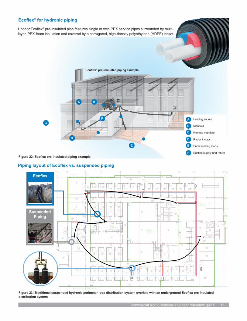
Heating source
Manifold
Remote manifold
Radiant loops
Snow melting loops
Ecoflex supply and return
A
B
C
D
E
F
B
C
D
E
F
Ecoflex
Suspended Piping
Ecoflex® for hydronic piping
Uponor Ecoflex® pre-insulated pipe features single or twin PEX service pipes surrounded by multi-layer, PEX-foam insulation and covered by a corrugated, high-density polyethylene (HDPE) jacket.
Piping layout of Ecoflex vs. suspended piping
Figure 22: Ecoflex pre-insulated piping example
Figure 23: Traditional suspended hydronic perimeter loop distribution system overlaid with an underground Ecoflex pre-insulated distribution system

Uponor Inc. 5925 148th Street West Apple Valley, MN 55124
T 800.321.4739 F 952.891.2008
ComPipingRefGuide_70108_0417_US, Copyright © 2016 Uponor. Printed in the United States. uponorengineering.com
Uponor Design and Estimation ServicesThe PEX design expertsProviding the mechanical, electrical and plumbing (MEP) industry with PEX design support since 1994, Uponor Design Services is a dedicated team of experienced design professionals and project managers trained in PEX applications for domestic water plumbing, radiant heating/cooling, hydronic piping and fire sprinkler systems for residential and commercial structures.
Uponor design advantage• Broad suite of services from concept to construction• Experienced staff of design professionals; industry-affiliated and certified
(ASHRAE, ASPE, RPA, NICET, NFPA, AFSA, NFSA)• Personalized project consultants for tailored support based on project phase• Specializing in PEX take-off and design• Optimized pipe sizing using unique properties of Uponor PEX systems• Efficient piping layouts using Uponor Logic design concepts• Estimates with labor data• Alternative piping material comparisons
BIM/CAD models• Uponor-hosted and maintained content• On-demand BIM/CAD model generation via Navigator on uponorpro.com
and uponorengineering.com• Revit® MEP system families• Fabrication CADmep® components, connectors and specifications• Providing the best digital experience for discovering and selecting
BIM/CAD content
Uponor is not liable for installation practices that deviate from this guide or are not acceptable practices within the mechanical trades, codes or standards of practice. Always refer to local codes for additional requirements.
Contact us today888.594.7726
For design assistance: [email protected]
For technical support: [email protected]
uponorengineering.com uponorpro.com
Powered byEnterprise Solutions™THOMAS
BIM/CAD models
Figure 25: CAD layout
Figure 24: BIM model