commercial door opener - liftmaster · raynor garage doors 1101 e. river road dixon, illinois 61021...
TRANSCRIPT

Raynor Garage Doors1101 E. River RoadDixon, Illinois 61021www.raynor.com
COMMERCIAL DOOR OPENER
Model ATS 211X-CX 1/2 HPFor Residential And Light Duty Commercial UseInstall on Sectional Doors Only
HIGH
LOW
NO RM
AL
HIGH
LOW
NO RM
AL
UPUP
FORCEFORCE
DOWNDOWN
FORCEFORCE
Owner’s Manual■ Please read this manual and the enclosed safety materials carefully!
■ Fasten the manual near the garage door after installation.
■ The door WILL NOT CLOSE unless the Protector System® is connected andproperly aligned.
■ Periodic checks of the opener are required to ensure safe operation.
■ The model number label is located on the front panel of your opener.

2
Introduction 2-5Safety symbol and signal word review........................2
Preparing your garage door ........................................3
Tools needed...............................................................3
Planning .....................................................................4
Carton inventory ..........................................................5
Hardware inventory .....................................................5
Assembly 6-7Attach the rail to the motor unit ...................................6
Attach the chain to the sprocket and install
the rail support bracket................................................6
Tighten the chain.........................................................7
Installation 7-23Installation safety instructions .....................................7
Determine the header bracket location .......................8
Install the header bracket............................................9
Attach the rail to the header bracket.........................10
Position the opener ...................................................11
Hang the opener........................................................11
Install the door control...............................................12
Install the light ...........................................................13
Attach the emergency release rope and handle .......13
Electrical requirements..............................................14
Install the Protector System®................................15-17
Fasten the door bracket ............................................18
Connect the door arm to the trolley ..........................19
Adjustment 20-22Adjust the travel limits ...............................................20
Adjust the force .........................................................21
Test the safety reversal system.................................22
Test the Protector System®........................................22
Operation 23-25Operation safety instructions.....................................23
Using your garage door opener ................................23
Using the wall-mounted door control ........................24
To open the door manually........................................24
Care of your garage door opener..............................24
Having a problem? ....................................................25
Programming 26-283-Channel remote controls (Optional) .......................26
Multi-Function door control (Optional).......................27
To add or change a Keyless Entry PIN (Optional) ....28
Repair Parts 29-32Rail assembly parts...................................................29
Installation parts ........................................................29
Motor unit assembly parts .........................................30
Accessories 31
Repair Parts and Service 32
Warranty 32
TABLE OF CONTENTS
When you see these Safety Symbols and SignalWords on the following pages, they will alert you tothe possibility of serious injury or death if you donot comply with the warnings that accompany them.The hazard may come from something mechanicalor from electric shock. Read the warnings carefully.
When you see this Signal Word on the followingpages, it will alert you to the possibility of damage toyour garage door and/or the garage door opener ifyou do not comply with the cautionary statementsthat accompany it. Read them carefully.
INTRODUCTIONSafety Symbol and Signal Word Review
This garage door opener has been designed and tested to offer safe service provided it is installed, operated,maintained and tested in strict accordance with the instructions and warnings contained in this manual.
Mechanical
Electrical
WARNARNINGING
CAUTION WARNING
WARNING
WARNING
CAUTION WARNING
WARNARNINGINGWARNING
CAUTIONCAUTION WARNING
WARNING

3
To prevent damage to garage door and opener:• ALWAYS disable locks BEFORE installing and operating
the opener. • ONLY operate garage door opener at 120V, 60 Hz to
avoid malfunction and damage.
To prevent possible SERIOUS INJURY OR DEATH:• ALWAYS call a trained door systems technician if
garage door binds, sticks, or is out of balance. Anunbalanced garage door may not reverse whenrequired.
• NEVER try to loosen, move or adjust garage door, doorsprings, cables, pulleys, brackets or their hardware, allof which are under EXTREME tension.
• Disable ALL locks and remove ALL ropes connected togarage door BEFORE installing and operating garagedoor opener to avoid entanglement.
• This product is for use on sectional garage doors only.SERIOUS INJURY could result from the use of thisproduct on one piece garage doors.
Preparing your garage door
Before you begin:
• Disable locks.
• Remove any ropes connected to garage door.
• Complete the following test to make sure yourgarage door is balanced and is not sticking orbinding:
1. Lift the door about halfway as shown. Releasethe door. If balanced, it should stay in place,supported entirely by its springs.
2. Raise and lower the door to see if there is anybinding or sticking.
If your door binds, sticks, or is out of balance, call atrained door systems technician.
Tools needed
During assembly, installation and adjustment of theopener, instructions will call for hand tools asillustrated below.
WARNARNINGING
CAUTION WARNING
WARNING
WARNING
CAUTIONCAUTION WARNING
WARNING
Pliers
Wire Cutters
Claw Hammer
Hack Saw
ScrewdriverAdjustable End Wrench
1/2" and 7/16" Socketsand Wrench
Drill
Tape Measure
21
Stepladder
Pencil
3/16", 5/16" and5/32" Drill Bits
Carpenter'sLevel (Optional)
Sectional Door
4
Safety Reversing Sensor
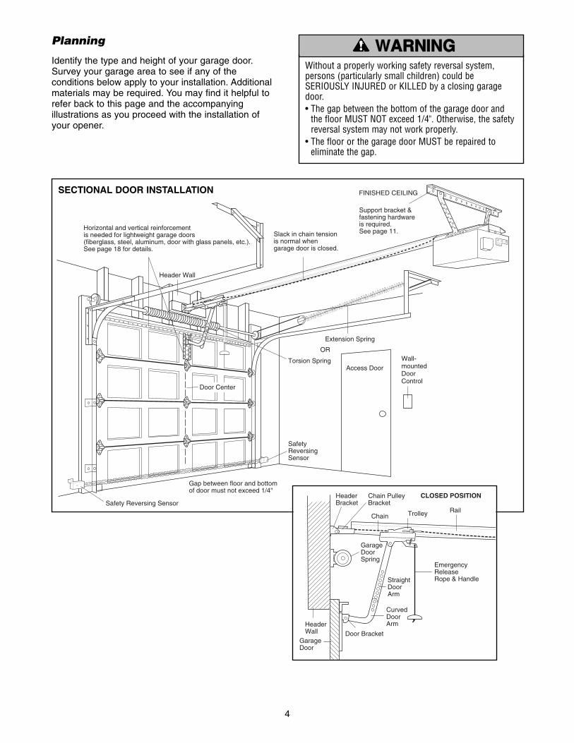
Horizontal and vertical reinforcementis needed for lightweight garage doors(fiberglass, steel, aluminum, door with glass panels, etc.).See page 18 for details.
Support bracket & fastening hardwareis required.See page 11.
— —
— —
— —
— —
Header Wall
SafetyReversingSensor
Gap between floor and bottom of door must not exceed 1/4"
FINISHED CEILING
Extension Spring
Torsion SpringAccess Door
OR
Slack in chain tensionis normal whengarage door is closed.
Door Center
Wall-mountedDoorControl
SECTIONAL DOOR INSTALLATION
Planning
Identify the type and height of your garage door.Survey your garage area to see if any of theconditions below apply to your installation. Additionalmaterials may be required. You may find it helpful torefer back to this page and the accompanyingillustrations as you proceed with the installation ofyour opener.
Chain PulleyBracket
HeaderBracket
Trolley
StraightDoorArm
EmergencyReleaseRope & Handle
Door Bracket Garage
Door
CurvedDoorArm
GarageDoorSpring
HeaderWall
Chain
CLOSED POSITION
Rail
Without a properly working safety reversal system,persons (particularly small children) could beSERIOUSLY INJURED or KILLED by a closing garagedoor.• The gap between the bottom of the garage door and
the floor MUST NOT exceed 1/4". Otherwise, the safetyreversal system may not work properly.
• The floor or the garage door MUST be repaired toeliminate the gap.
WARNARNINGING
CAUTION WARNING
WARNING

5
StraightDoor Arm
Door Bracket PlateDoor Bracket
Safety Labelsand Literature
"C" Wrap (2)
2 -Conductor Bell WireWhite & White/Red
Curved Door Arm
Rail
Styrofoam
ChainPulley Bracket
Trolley
Chain
Safety Reversing SensorMounting BracketWith Slot (2)
Safety Reversing SensorMounting BracketWith Square Holes (2)
Mounting Hardware(Rail Support Bracket)
Header Bracket withClevis Pin and Fastener
UP
CEILING MOUNT ONLY
Lighted DoorControl Button
(2) Safety Reversing Sensors(1 Sending Eye and 1 Receiving Eye)with 2-Conductor White & White/Black Bell Wire attached
Rail SupportBracket
HIGH
LOW
NO RM
AL
HIGH
LOW
NO RM
AL
UP
FORCE
DOWN
FORCE
Motor Unit
Your garage door opener is packaged in two cartonswhich contain the motor unit and all parts illustratedbelow. Accessories will depend on the model
purchased. If anything is missing, carefully check thepacking material. Parts may be stuck in the foam.Hardware for installation is also listed below.
Carton Inventory
Assembly Hardware
Washered Bolt, 5/16"-18x1/2" (2)(Mounted in Opener)Hex Screw 1/4"-20x5/8" (2)Lock Washer 1/4"-20x5/8" (2)Screw #8-32x3/8" (1)Washered Bolt 5/16"-18x1/2" (2)
Installation Hardware
Hex Screw 5/16"-18x7/8" (4)Nut 5/16"-18 (6)Lock Washer 5/16" (6)Rail GreaseLag Screw 5/16"-9x1-5/8" (2)Lag Screw 5/16"-18x1-7/8" (2)Screw 6ABx1-1/2" (2)Handle Ring Fastener (3)Carriage Bolt 5/16"-18x2-1/2" (2)Insulated Staples (10)Dry Wall Anchors (2)Clevis Pin 5/16"x2-3/4" (1)Clevis Pin 5/16"x1" (2)Rope
Hardware for Safety Reversing Sensor
Lag Screw 1/4x1-1/2" (4)Carriage Bolt 1/4"-20x1/2" (4)Lock Nut 1/4"-20 (4)Wing Nut (2)Hex Screw 1/4-20x1-1/2" (2)Screw #10-32x3/8" (4)Lock Nut #10x32 (4)Insulated Staples (20)
HARDWARE INVENTORY

6
ASSEMBLY STEP 1Attach the Rail to the Motor Unit
To avoid installation difficulties, do not run thegarage door opener until instructed to do so.• Place the opener on packing material to protect
the cover.
• Remove the (2) 5/16"-18x1/2" washered boltsmounted in the top of the motor unit.
• Position rail at a 45˚ angle to opener so one hole inrail and motor unit line up.
• Thread one of the washered bolts part way in.
Use only these bolts! Use of any other bolts willcause serious damage to door opener.• Align rail over sprocket. Cut tape from rail.
ChainSpreader
Sprocket
Chain
USE ONLY THISTYPE AND SIZE
BOLT
Opener
Washered Bolt5/16"-18x1/2"
Rail
To avoid SERIOUS damage to opener, ONLY usebolts/fasteners mounted in top of motor unit.
WARNING
CAUTIONCAUTION WARNING
WARNING
ASSEMBLY STEP 2Attach the Chain to the Sprocketand Install the Rail Support Bracket
• Guide the chain over chain spreader and openersprocket. If necessary, loosen the outer nut on thetrolley to obtain more chain slack. Insert the secondwashered bolt. Use only the bolts previouslyremoved from opener.
• Tighten both bolts securely through the rail into theopener as shown.
• Position the rail support bracket on the opener.
• Attach the bracket to the rail with 1/4"-20x5/8"hex bolts and lock washers. Do not overtighten.
• Attach the bracket to the opener by inserting a5/16"-18x1/2" washered bolt through a hole in eachside flange and a matching hole in the bracket.Complete the connection by inserting the #8-32x3/8" screw through the back flange and thehole in rail support.
Proceed to Assembly Step 3.
To avoid possible SERIOUS INJURY to fingers frommoving garage door opener:• ALWAYS keep hand clear of sprocket while operating
opener.• Securely attach rail support bracket BEFORE operating.
WARNARNINGING
CAUTION WARNING
WARNING
Hex boltswith Lock Washers1/4"-20x5/8"
Rail SupportBracket
Washered Bolt5/16"-18x1/2"
Washered Bolt5/16"-18x1/2"
Screw#8-32x3/8"
OpenerSide Flange
OpenerBack Flange
Washered Bolt5/16"-18x1/2"
Hex Bolt1/4"-20x5/8"
Screw#8-32x3/8"
Lock Washer
HARDWARE SHOWN ACTUAL SIZE

7
ASSEMBLY STEP 3Tighten the Chain
• Spin the inner nut and lock washer down thethreaded shaft, away from the trolley.
• To tighten the chain, turn outer nut in the directionshown. As you turn the nut, keep the chain fromtwisting.
• When the chain is approximately 1/2" (1.27 cm)above the base of the rail at its midpoint, re-tightenthe inner nut to secure the adjustment.
Sprocket noise can result if chain is either tooloose or too tight.When installation is complete, you may notice somechain droop with the door closed. This is normal. Ifthe chain returns to the position shown when thedoor is open, do not re-adjust the chain.
NOTE: During future maintenance, ALWAYS pull theemergency release handle to disconnect trolleybefore adjusting chain.
You have now finished assembling your garagedoor opener. Please read the following warningsbefore proceeding to the installation section.
To TightenInner Nut
LockWasher
To Tighten Outer NutInner Nut
Trolley
Chain
Base of Rail
1/2" (1.27 cm)
Outer Nut
IMPORTANT INSTALLATION INSTRUCTIONS
1. READ AND FOLLOW ALL INSTALLATION WARNINGSAND INSTRUCTIONS.
2. Install garage door opener ONLY on properly balancedand lubricated garage door. An improperly balanceddoor may not reverse when required and could result inSEVERE INJURY or DEATH.
3. All repairs to cables, spring assemblies and otherhardware MUST be made by a trained door systemstechnician BEFORE installing opener.
4. Disable all locks and remove all ropes connected togarage door BEFORE installing opener to avoidentanglement.
5. Install garage door opener 7 feet or more above floor.6. Mount emergency release handle 6 feet above floor.7. NEVER connect garage door opener to power source
until instructed to do so.
8. NEVER wear watches, rings or loose clothing whileinstalling or servicing opener. They could be caught ingarage door or opener mechanisms.
9. Install wall-mounted garage door control:• within sight of the garage door • out of reach of children at minimum height of 5 feet• away from all moving parts of the door.
10. Place entrapment warning label on wall next to garagedoor control.
11. Place manual release/safety reverse test label in plainview on inside of garage door.
12. Upon completion of installation, test safety reversalsystem. Door MUST reverse on contact with a 1-1/2” high object (or a 2x4 laid flat) on the floor.
To reduce the risk of SEVERE INJURY or DEATH:WARNARNINGING
WARNING
WARNING
INSTALLATION

8
INSTALLATION STEP 1Determine the Header BracketLocation
1. Close the door and mark the inside verticalcenterline of the garage door.
2. Extend the line onto the header wall above thedoor.
You can fasten the header bracket within 4 feetof the left or right of the door center only if atorsion spring or center bearing plate is in theway; or you can attach it to the ceiling (seepage 9) when clearance is minimal. (It may bemounted on the wall upside down if necessary,to gain approximately 1/2".)If you need to install the header bracket on a 2x4(on wall or ceiling), use lag screws (not provided)to securely fasten the 2x4 to structural supports asshown here and on page 9.
3. Open your door to the highest point of travel asshown. Draw an intersecting horizontal line on theheader wall 2" (5 cm) above the high point. Thisheight will provide travel clearance for the top edgeof the door.
Proceed to Step 2, page 9.
To prevent possible SERIOUS INJURY or DEATH:• Header bracket MUST be RIGIDLY fastened to
structural support on header wall or ceiling, otherwisegarage door might not reverse when required. DO NOTinstall header bracket over drywall.
• Concrete anchors MUST be used if mounting headerbracket or 2x4 into masonry.
• NEVER try to loosen, move or adjust garage door,springs, cables, pulleys, brackets, or their hardware, allof which are under EXTREME tension.
• ALWAYS call a trained door systems technician ifgarage door binds, sticks, or is out of balance. Anunbalanced garage door might not reverse whenrequired.
Header Wall
Sectional door with curved track
Highest Pointof Travel
Door
2" (5 cm) Track
Sectional doorwith curvedtrack
FinishedCeiling
HeaderWall 2x4 Structural
Supports
Vertical Centerlineof Garage Door
WARNARNINGING
CAUTION WARNING
WARNING
9
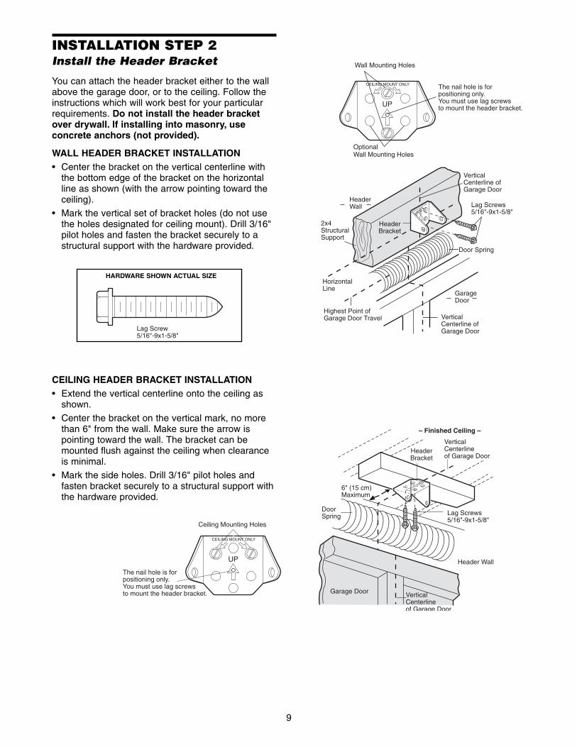
INSTALLATION STEP 2Install the Header Bracket
You can attach the header bracket either to the wallabove the garage door, or to the ceiling. Follow theinstructions which will work best for your particularrequirements. Do not install the header bracketover drywall. If installing into masonry, useconcrete anchors (not provided).
WALL HEADER BRACKET INSTALLATION• Center the bracket on the vertical centerline with
the bottom edge of the bracket on the horizontalline as shown (with the arrow pointing toward theceiling).
• Mark the vertical set of bracket holes (do not usethe holes designated for ceiling mount). Drill 3/16"pilot holes and fasten the bracket securely to astructural support with the hardware provided.
Lag Screw5/16"-9x1-5/8"
HARDWARE SHOWN ACTUAL SIZE
Lag Screws5/16"-9x1-5/8"
Highest Point of Garage Door Travel
VerticalCenterline ofGarage Door
HeaderWall
GarageDoor
UP
CEILING MOUNT ONLY
Wall Mounting Holes
Optional Wall Mounting Holes
The nail hole is forpositioning only. You must use lag screws to mount the header bracket.
UPCEILING MOUNT ONLY
Door Spring
HeaderBracket
2x4StructuralSupport
VerticalCenterline ofGarage Door
HorizontalLine
UP
CEILING MOUNT ONLY
Ceiling Mounting Holes
The nail hole is for positioning only.You must use lag screws to mount the header bracket.
UP
Lag Screws5/16"-9x1-5/8"
Garage Door
VerticalCenterlineof Garage Door
Header Wall
– Finished Ceiling –
HeaderBracket
6" (15 cm) Maximum
VerticalCenterlineof Garage Door
DoorSpring
CEILING HEADER BRACKET INSTALLATION• Extend the vertical centerline onto the ceiling as
shown.
• Center the bracket on the vertical mark, no morethan 6" from the wall. Make sure the arrow ispointing toward the wall. The bracket can bemounted flush against the ceiling when clearanceis minimal.
• Mark the side holes. Drill 3/16" pilot holes andfasten bracket securely to a structural support withthe hardware provided.
10
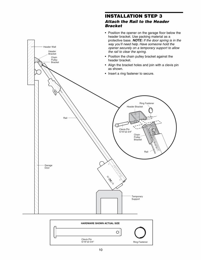
Clevis Pin5/16"x2-3/4" Ring Fastener
HeaderBracket
ChainPulleyBracket
TemporarySupport
Header Wall
GarageDoor
Rail
Clevis Pin5/16"x2-3/4"
Ring Fastener
Header Bracket
ChainPulleyBracket
Rail
HARDWARE SHOWN ACTUAL SIZE
INSTALLATION STEP 3Attach the Rail to the HeaderBracket
• Position the opener on the garage floor below theheader bracket. Use packing material as aprotective base. NOTE: If the door spring is in theway you’ll need help. Have someone hold theopener securely on a temporary support to allowthe rail to clear the spring.
• Position the chain pulley bracket against theheader bracket.
• Align the bracket holes and join with a clevis pinas shown.
• Insert a ring fastener to secure.
11
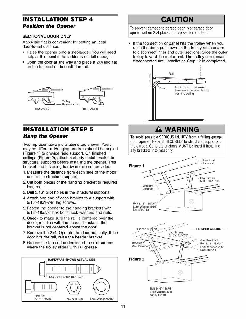
INSTALLATION STEP 4Position the Opener
SECTIONAL DOOR ONLYA 2x4 laid flat is convenient for setting an ideal door-to-rail distance. • Raise the opener onto a stepladder. You will need
help at this point if the ladder is not tall enough.• Open the door all the way and place a 2x4 laid flat
on the top section beneath the rail.
Trolley Release Arm
ENGAGED RELEASED
To prevent damage to garage door, rest garage dooropener rail on 2x4 placed on top section of door.
WARNING
CAUTIONCAUTION WARNING
WARNING
• If the top section or panel hits the trolley when you raise the door, pull down on the trolley release armto disconnect inner and outer sections. Slide the outertrolley toward the motor unit. The trolley can remaindisconnected until Installation Step 12 is completed.
Rail
2x4 is used to determinethe correct mounting heightfrom the ceiling
Door
INSTALLATION STEP 5Hang the Opener
Two representative installations are shown. Yoursmay be different. Hanging brackets should be angled(Figure 1) to provide rigid support. On finishedceilings (Figure 2), attach a sturdy metal bracket tostructural supports before installing the opener. Thisbracket and fastening hardware are not provided. 1. Measure the distance from each side of the motor
unit to the structural support.2. Cut both pieces of the hanging bracket to required
lengths.3. Drill 3/16" pilot holes in the structural supports.4. Attach one end of each bracket to a support with
5/16"-18x1-7/8" lag screws.5. Fasten the opener to the hanging brackets with
5/16"-18x7/8" hex bolts, lock washers and nuts.6. Check to make sure the rail is centered over the
door (or in line with the header bracket if thebracket is not centered above the door).
7. Remove the 2x4. Operate the door manually. If thedoor hits the rail, raise the header bracket.
8. Grease the top and underside of the rail surfacewhere the trolley slides with rail grease.
To avoid possible SERIOUS INJURY from a falling garagedoor opener, fasten it SECURELY to structural supports ofthe garage. Concrete anchors MUST be used if installingany brackets into masonry.
Lag Screw 5/16"-18x1-7/8"
Hex Bolt5/16"-18x7/8" Nut 5/16"-18 Lock Washer 5/16"
HARDWARE SHOWN ACTUAL SIZE
Bolt 5/16"-18x7/8" Lock Washer 5/16" Nut 5/16"-18
MeasureDistance
Lag Screws5/16"-18x1-7/8"
StructuralSupports
Lag Screws5/16"-18x1-7/8"
Bracket(Not Provided)
FINISHED CEILING
(Not Provided)Bolt 5/16"-18x7/8" Lock Washer 5/16" Nut 5/16"-18
Bolt 5/16"-18x7/8"Lock Washer 5/16"Nut 5/16"-18
Hidden Support
Figure 1
Figure 2
WARNARNINGING
CAUTION WARNING
WARNING

12
Drywall AnchorsInsulatedStaples
Screw 6ABx1-1/2" Lighted Door Control Button
HARDWARE SHOWN ACTUAL SIZE
To prevent possible SERIOUS INJURY or DEATH fromelectrocution:• Be sure power is not connected BEFORE installing door
control.• Connect ONLY to 24 VOLT low voltage wires. To prevent possible SERIOUS INJURY or DEATH from aclosing garage door:• Install door control within sight of garage door, out of
reach of children at a minimum height of 5 feet (1.5 m),and away from all moving parts of door.
• NEVER permit children to operate or play with doorcontrol push buttons or remote control transmitters.
• Activate door ONLY when it can be seen clearly, isproperly adjusted, and there are no obstructions to doortravel.
• ALWAYS keep garage door in sight until completelyclosed. NEVER permit anyone to cross path of closinggarage door.
WARNING
CAUTION WARNARNINGING
WARNING
Outside Keylock Accessory ConnectionsTo opener terminal screws: White to 2 andwhite/red to 1.
Lighted Door ControlButton
2-ConductorBell Wire
KG KG
1
3
9
7
5
1
3
9
7
5
2 31
OpenerTerminalScrews
AntennaBack Panelof Opener
LightedDoor ControlTerminal Screws
2-ConductorBell Wire
WHT
RED
-2
-1
INSTALLATION STEP 6Install the Door Control
Locate the door control within sight of the door at aminimum height of 5 feet (1.5 m) where smallchildren cannot reach, and away from all movingparts of the door and door hardware.
1. Strip 1/4" (6 mm) of insulation from one end of thebell wire. Connect it to the two screw terminals onthe back of the door control by color: white wire to2 and white/red wire to 1.
2. Fasten the Lighted Door Control Button securelywith 6ABx1-1/2" screws. If installing into drywall,drill 5/32" holes and use the anchors provided.
3. Run the bell wire up the wall and across theceiling to the opener. Use insulated staples tosecure the wire in several places. Be careful not topierce the wire with a staple, creating a short oropen circuit.
4. Receiver terminal screws and the antenna arelocated on the back panel of the motor unit.Position the antenna wire as shown.
5. Connect the bell wire by color to the openerterminal screws: white to 2 and white/red to 1.
6. Use tacks or staples to permanently attach theentrapment warning label to the wall near the doorcontrol, and the manual release/safety reverse testin a prominent location on the inside of the garage door.
NOTE: DO NOT connect the power and operate theopener at this time. The trolley will travel to the fullopen position, but will not return to the close positionuntil the sensor beam is connected and properlyaligned. See Safety Reversing Sensor instructionsbeginning on page 15.

13
INSTALLATION STEP 7Install the Light
• Install a 75 watt maximum light bulb into thesocket. Light bulb size should be A19, standardneck only. The lights will turn ON and remain lit forapproximately 4-1/2 minutes when power isconnected. Then the lights will turn OFF.
• Reverse the procedure to close the lens.
• Use A19, standard neck garage door opener bulbsfor replacement.
NOTE: Use only standard light bulbs. The use ofshort neck or speciality light bulbs may overheat theendpanel or light socket.
INSTALLATION STEP 8Attach the Emergency ReleaseRope and Handle
• Thread one end of the rope through the hole in thetop of the red handle so “NOTICE” reads right sideup as shown. Secure with an overhand knot atleast 1" from the end of the rope to preventslipping.
• Thread the other end of the rope through the holein the release arm of the outer trolley.
• Adjust rope length so the handle is 6 feet abovethe floor. Secure with an overhand knot.
NOTE: If it is necessary to cut the rope, heat sealthe cut end with a match or lighter to preventunraveling.
To prevent possible SERIOUS INJURY or DEATH from afalling garage door:• If possible, use emergency release handle to
disengage trolley ONLY when garage door is CLOSED.Weak or broken springs or unbalanced door couldresult in an open door falling rapidly and/orunexpectedly.
• NEVER use emergency release handle unless garagedoorway is clear of persons and obstructions.
• NEVER use handle to pull door open or closed. If ropeknot becomes untied, you could fall.
Trolley
NOTICE
OverhandKnot
EmergencyRelease Handle
RopeTrolleyRelease Arm
WARNING
CAUTION WARNING
WARNING
Opener
75 Watt Max.Light Bulb
To prevent possible OVERHEATING of the endpanel orlight socket:• DO NOT use short neck or specialty light bulbs.• DO NOT use halogen bulbs. Use ONLY incandescent.To prevent damage to the opener:• DO NOT use bulbs larger than 100W.• ONLY use A19 size bulbs.
WARNING
CAUTION WARNING
WARNING

14
INSTALLATION STEP 9Electrical Requirements
To avoid installation difficulties, do not run theopener at this time.To reduce the risk of electric shock, your garage dooropener has a grounding type plug with a thirdgrounding pin. This plug will only fit into a groundingtype outlet. If the plug doesn't fit into the outlet youhave, contact a qualified electrician to install theproper outlet.
If permanent wiring is required by your localcode, refer to the following procedure.To make a permanent connection through the 7/8"hole in the top of the motor unit:
• Remove the motor unit cover screws and set thecover aside.
• Remove the attached 3-prong cord.
• Connect the black (line) wire to the screw on thebrass terminal; the white (neutral) wire to thescrew on the silver terminal; and the ground wireto the green ground screw. The opener must begrounded.
• Reinstall the cover.
To avoid installation difficulties, do not run theopener at this time.
RIGHT WRONG
To prevent possible SERIOUS INJURY or DEATH fromelectrocution or fire:• Be sure power is not connected to the opener, and
disconnect power to circuit BEFORE removing cover toestablish permanent wiring connection.
• Garage door installation and wiring MUST be incompliance with all local electrical and building codes.
• NEVER use an extension cord, 2-wire adapter, orchange plug in ANY way to make it fit outlet. Be surethe opener is grounded.
Ground Tab
Green Ground Screw
Ground Wire
Black Wire
PERMANENT WIRINGCONNECTION
White Wire
BlackWire
WARNING
CAUTION WARNING
WARNARNINGING
15
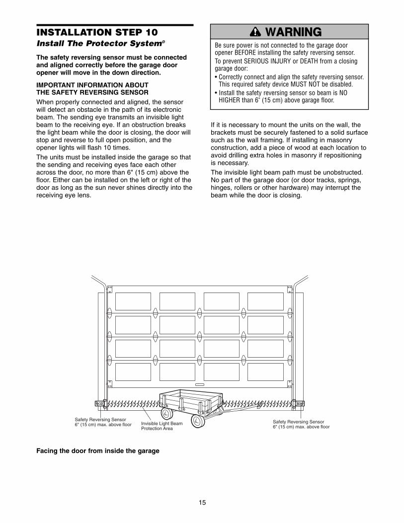
Invisible Light BeamProtection Area
Safety Reversing Sensor6" (15 cm) max. above floor
Safety Reversing Sensor6" (15 cm) max. above floor
Facing the door from inside the garage
INSTALLATION STEP 10Install The Protector System®
The safety reversing sensor must be connectedand aligned correctly before the garage dooropener will move in the down direction.
IMPORTANT INFORMATION ABOUT THE SAFETY REVERSING SENSORWhen properly connected and aligned, the sensorwill detect an obstacle in the path of its electronicbeam. The sending eye transmits an invisible lightbeam to the receiving eye. If an obstruction breaksthe light beam while the door is closing, the door willstop and reverse to full open position, and theopener lights will flash 10 times.
The units must be installed inside the garage so thatthe sending and receiving eyes face each otheracross the door, no more than 6" (15 cm) above thefloor. Either can be installed on the left or right of thedoor as long as the sun never shines directly into thereceiving eye lens.
If it is necessary to mount the units on the wall, thebrackets must be securely fastened to a solid surfacesuch as the wall framing. If installing in masonryconstruction, add a piece of wood at each location toavoid drilling extra holes in masonry if repositioningis necessary.
The invisible light beam path must be unobstructed.No part of the garage door (or door tracks, springs,hinges, rollers or other hardware) may interrupt thebeam while the door is closing.
Be sure power is not connected to the garage dooropener BEFORE installing the safety reversing sensor.To prevent SERIOUS INJURY or DEATH from a closinggarage door:• Correctly connect and align the safety reversing sensor.
This required safety device MUST NOT be disabled.• Install the safety reversing sensor so beam is NO
HIGHER than 6" (15 cm) above garage floor.
WARNARNINGING
CAUTION WARNING
WARNING

16
InsideGarageWall
“C” ShapedWrap
Mounting Bracketwith Square Holes
1/4-20x1/2"Carriage Bolts
1/4"-20 Lock Nuts
Drill 3/8"Holes
GarageDoor Track
Figure 3 Garage DOOR Track Installation
Mounting BracketWith Square Holes
#10-32x3/8"Screws
“C” Wrap
#10-32Lock Nuts
Figure 1 Garage WALL or DOOR Track Installation
Mounting Bracketwith Slot
1/4"-20Lock Nuts
1/4x1-1/2"Lag Screws
1/4-20x1/2" Carriage Bolts(with square shoulder)
InsideGarageWall
“C” Wrap
Mounting Bracketwith Square Holes
Figure 2 Garage WALL Installation
Lag Screw 1/4x1-1/2"Screw#10-32x3/8"
Lock Nut1/4"-20
Lock Nut#10x32 Staples
Carriage Bolts1/4"-20x1/2"
HARDWARE SHOWN ACTUAL SIZE
Figure 4 Alternate Wall Mount
“C” Wrap
InsideGarageWall
Mounting Bracketwith Square Holes
Mounting Bracketwith Slot
Sensorwith wire
Indicator Light
GarageFloor
INSTALLING THE BRACKETSFigure 1, 2 and 3 show recommended assembly ofbracket(s) and “C” wrap based on the wallinstallation of the sensors on each side of the garagedoor as shown on page 15, or on the garage doortracks themselves.
Figure 4 and 5 are variations which may fit yourinstallation requirements better. Make sure thewraps and brackets are aligned so the sensorswill face each other across the garage door.
Garage Wall or Door Track Installation1. Fasten the “C” wraps to the mounting brackets
having square holes, using th hardware shown inFigure 1.
Garage Wall Installation2. Connect each assembly to a slotted bracket, using
the hardware shown on Figure 2. Note alignmentof brackets for left and right sides of door.
3. Finger tighten the lock nuts.
4. Use bracket mounting holes as a template tolocate and drill (2) 3/16" diameter pilot holes onboth sides of the garage door, 4"-6" above thefloor but not exceeding 6" (see warning on page 15).
5. Attach bracket assembly with 1/4"x1-1/2" lagscrews as shown in Figure 2.
6. Adjust right and left bracket assemblies to thesame distance out from mounting surface. Makesure all door hardware obstructions are cleared.Tighten the nuts securely.
Garage Door Track InstallationDiscard slotted bracket. Drill 3/8" holes in each trackand fasten securely with hardware as shown inFigure 3.
GarageFloor
Indicator Light
InsideGarageWall
Mounting Bracketwith Slot
Attach withconcreteanchors(not provided)
Mounting Bracketwith Square Holes
“C” Wrap
Sensor with wire
Figure 5 Alternate Floor Mount
TROUBLESHOOTING THE SAFETY REVERSINGSENSORS1. If the sending eye indicator light does not glow
steadily after installation, check for:
• Electric power to the opener.
• A short in the white or white/black wires. Thesecan occur at staples, or at opener connections.
• Incorrect wiring between sensors and opener.
• A broken wire.
2. If the sending eye indicator light glows steadily butthe receiving eye indicator light doesn't:
• Check alignment.
• Check for an open wire to the receiving eye.
3. If the receiving eye indicator light is dim, realigneither sensor.
NOTE: When the invisible beam path is obstructedor misaligned while the door is closing, the door willreverse. If the door is already open, it will not close.The opener lights will blink 10 times. (If bulbs are notinstalled, 10 clicks can be heard.) See page 15.
17
Hex Bolt1/4-20 x 1-1/2"
"C" Wrap
Sensorwith Wire
WingNut
Indicator Light
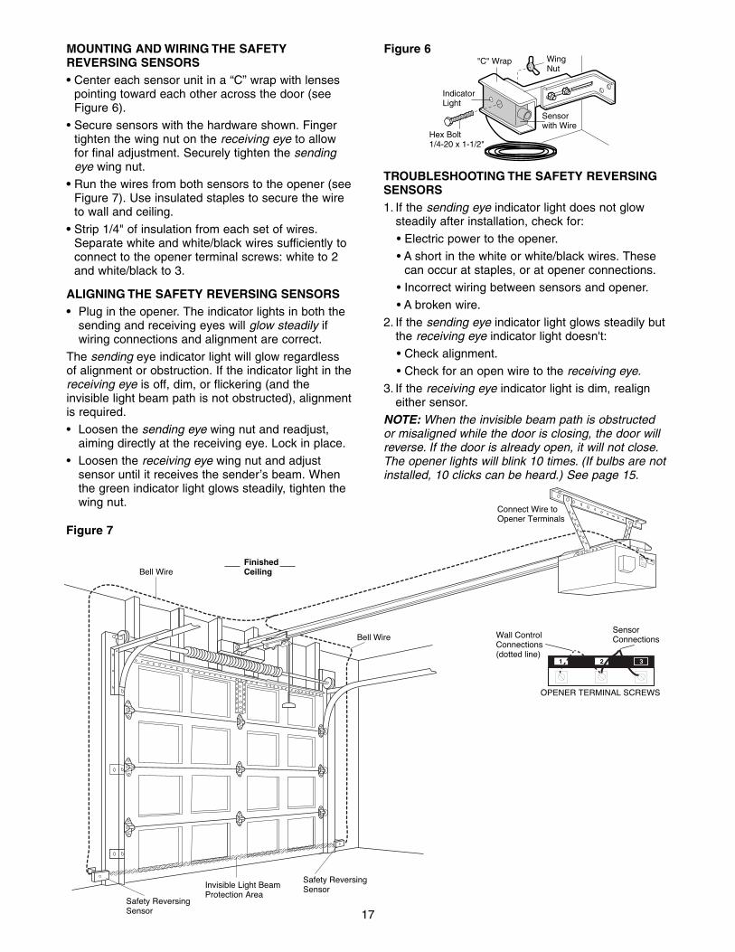
Figure 6
Invisible Light BeamProtection Area
Safety ReversingSensor
Safety ReversingSensor
Connect Wire toOpener Terminals
Bell Wire
Bell WireFinishedCeiling
SensorConnectionsWall Control
Connections(dotted line)
OPENER TERMINAL SCREWS
1 2 3
Figure 7
MOUNTING AND WIRING THE SAFETYREVERSING SENSORS• Center each sensor unit in a “C” wrap with lenses
pointing toward each other across the door (seeFigure 6).
• Secure sensors with the hardware shown. Fingertighten the wing nut on the receiving eye to allowfor final adjustment. Securely tighten the sendingeye wing nut.
• Run the wires from both sensors to the opener (seeFigure 7). Use insulated staples to secure the wireto wall and ceiling.
• Strip 1/4" of insulation from each set of wires.Separate white and white/black wires sufficiently toconnect to the opener terminal screws: white to 2and white/black to 3.
ALIGNING THE SAFETY REVERSING SENSORS• Plug in the opener. The indicator lights in both the
sending and receiving eyes will glow steadily ifwiring connections and alignment are correct.
The sending eye indicator light will glow regardlessof alignment or obstruction. If the indicator light in thereceiving eye is off, dim, or flickering (and theinvisible light beam path is not obstructed), alignmentis required.
• Loosen the sending eye wing nut and readjust,aiming directly at the receiving eye. Lock in place.
• Loosen the receiving eye wing nut and adjustsensor until it receives the sender’s beam. Whenthe green indicator light glows steadily, tighten thewing nut.

18
If your installation doesn’t require vertical reinforcement but does need top and bottomfastening holes for the door bracket, fasten as shownin Figure 2.
INSTALLATION STEP 11Fasten the Door BracketA horizontal brace should be long enough to besecured to 2 vertical supports. A vertical braceshould cover the height of the top panel.The illustration shows one piece of angle iron as thehorizontal brace. For the vertical brace, 2 pieces ofangle iron are used to create a “U”-shaped support.The best solution is to check with your garage doormanufacturer for an opener installation doorreinforcement kit.
• Center the door bracket on the previously markedvertical guideline used for the header bracketinstallation.
• Position the bracket on the face of the door withinthe following limits:
A) The top edge of the bracket 2"-4" (5-10 cm)below the top edge of the door.
B) The top edge of the bracket directly below anystructural support across the top of the door.
• Mark and drill 5/16" left and right fastening holes.Secure the bracket as shown in Figure 1 if there isvertical reinforcement.
VerticalCenterlineof GarageDoor
DoorBracketLocation
Header BracketHorizontal and vertical reinforcementis needed for lightweight garage doors(fiberglass, aluminum, steel, doors withglass panel, etc.). (Not Provided)
UP
Door Bracket
Inside Edgeof Door orReinforcement Board Door
Bracket
Nut5/16"-18
Carriage Bolt5/16"-18x2-1/2"
Lock Washer5/16"
VerticalCenterlineof GarageDoor
UP
VerticalReinforcement
Carriage Bolt5/16"-18x2-1/2"
Nut 5/16"-18 Lock Washer 5/16"
HARDWARE SHOWN ACTUAL SIZE
Figure 2
Figure 1
Fiberglass, aluminum or lightweight steel garage doorsWILL REQUIRE reinforcement BEFORE installation ofdoor bracket. Contact your door manufacturer forreinforcement kit.
WARNING
CAUTIONCAUTION WARNING
WARNING

19
INSTALLATION STEP 12Connect Door Arm to Trolley
SECTIONAL DOORS ONLY• Make sure garage door is fully closed. Pull the
emergency release handle to disconnect the outertrolley from the inner trolley. Slide the outer trolleyback (away from the door) about 2" as shown inFigures 1, 2 and 3.
• Figure 1:– Fasten straight door arm section to outer trolley
with the 5/16"x1" clevis pin. Secure theconnection with a ring fastener.
– Fasten curved section to the door bracket in thesame way, using the 5/16"x1" clevis pin.
• Figure 2:– Bring arm sections together. Find two pairs of
holes that line up and join sections. Select holesas far apart as possible to increase door armrigidity.
• Figure 3, Hole Alignment Alternative:– If holes in curved arm are above holes in straight
arm, disconnect straight arm. Cut about 6" fromthe solid end. Reconnect to trolley with cut enddown as shown.
– Bring arm sections together.
– Find two pairs of holes that line up and join withbolts, lock washers and nuts.
• Proceed to Adjustment Step 1, page 20. Trolley willre-engage automatically when opener is operated.
Ring Fastener
DoorBracket
Clevis Pin5/16"x1-1/4"
CurvedDoor Arm
StraightDoor Arm
Clevis Pin5/16"x1"
Inner Trolley
Outer Trolley
LockWashers5/16"
Nuts5/16"-18
Door Bracket
Bolts5/16"-18x7/8"
EmergencyReleaseHandle
LockWashers5/16"
Nuts5/16"-18
Bolts5/16"-18x7/8"
Cut This End
Figure 1
Figure 2
Figure 3
Lock Washer 5/16"Nut 5/16"-18 Ring Fastener
Hex Bolt5/16"-18x7/8"
Clevis Pin5/16"x1"
HARDWARE SHOWN ACTUAL SIZE

20
ADJUSTMENT STEP 1Adjust the UP and DOWN TravelLimitsLimit adjustment settings regulate the points at whichthe door will stop when moving up or down.
To operate the opener, press the Door Control pushbar. Run the opener through a complete travel cycle.
• Does the door open and close completely?
• Does the door stay closed and not reverseunintentionally when fully closed?
If your door passes both of these tests, no limitadjustments are necessary unless the reversing testfails (Adjustment Step 3, page 22).
Adjustment procedures are outlined below. Read theprocedures carefully before proceeding toAdjustment Step 2. Use a screwdriver to make limitadjustments. Run the opener through a completetravel cycle after each adjustment.NOTE: Repeated operation of the opener duringadjustment procedures may cause the motor tooverheat and shut off. Simply wait 15 minutes andtry again.
NOTE: If anything interferes with the door’s upwardtravel, it will stop. If anything interferes with the door’sdownward travel (including binding or unbalanceddoors), it will reverse.
HOW AND WHEN TO ADJUST THE LIMITS
• If the door does not open completely but opensat least five feet:Increase up travel. Turn the UP limit adjustmentscrew clockwise. One turn equals 2" of travel.
NOTE: To prevent the trolley from hitting the coverprotection bolt, keep a minimum distance of 2-4"between the trolley and the bolt.
• If door does not open at least 5 feet:Adjust the UP (open) force as explained inAdjustment Step 2.
• If the door does not close completely:Increase down travel. Turn the down limitadjustment screw counterclockwise. One turnequals 2" of travel.
If door still won't close completely and the trolleybumps into the pulley bracket (page 4), trylengthening the door arm (page 19) anddecreasing the down limit.
• If the opener reverses in fully closed position:Decrease down travel. Turn the down limitadjustment screw clockwise. One turn equals 2"of travel.
Without a properly installed safety reversal system,persons (particularly small children) could beSERIOUSLY INJURED or KILLED by a closing garagedoor.• Incorrect adjustment of garage door travel limits will
interfere with proper operation of safety reversalsystem.
• If one control (force or travel limits) is adjusted, theother control may also need adjustment.
• After ANY adjustments are made, the safety reversalsystem MUST be tested. Door MUST reverse oncontact with 1-1/2" high object (or 2x4 laid flat) onfloor.
• If the door reverses when closing and there isno visible interference to travel cycle:If the opener lights are flashing, the SafetyReversing Sensors are either not installed,misaligned, or obstructed. See Troubleshooting,page 17.
Test the door for binding: Pull the emergencyrelease handle. Manually open and close the door.If the door is binding or unbalanced, call for atrained door systems technician. If the door isbalanced and not binding, adjust the DOWN(close) force. See Adjustment Step 2.
LimitAdjustmentScrews
Adjustment Label
Left SidePanel
Cover Protection Bolt
2-4"
WARNARNINGING
CAUTION WARNING
WARNING
To prevent damage to vehicles, be sure fully open doorprovides adequate clearance.
WARNING
CAUTIONCAUTION WARNING
WARNING

21
ADJUSTMENT STEP 2Adjust the ForceForce adjustment controls are located on the backpanel of the motor unit. Force adjustment settingsregulate the amount of power required to open andclose the door.
If the forces are set too light, door travel may beinterrupted by nuisance reversals in the downdirection and stops in the up direction. Weatherconditions can affect the door movement, sooccasional adjustment may be needed.
The maximum force adjustment range is about3/4 of a complete turn. Do not force controlsbeyond that point. Turn force adjustment controlswith a screwdriver.
NOTE: If anything interferes with the door’s upwardtravel, it will stop. If anything interferes with the door’sdownward travel (including binding or unbalanceddoors), it will reverse.
HOW AND WHEN TO ADJUST THE FORCES1. Test the DOWN (close) force• Grasp the door bottom when the door is about
halfway through DOWN (close) travel. The doorshould reverse. Reversal halfway through downtravel does not guarantee reversal on a 1.5"obstruction. See Adjustment Step 3, page 22.If the door is hard to hold or does not reverse,DECREASE the DOWN (close) force by turningthe control counterclockwise. Make smalladjustments until the door reverses normally. Aftereach adjustment, run the opener through acomplete cycle.
• If the door reverses during the down (close)cycle and the opener lights are not flashing,INCREASE DOWN (close) force by turning thecontrol clockwise. Make small adjustments until thedoor completes a close cycle. After eachadjustment, run the opener through a completetravel cycle. Do not increase the force beyond theminimum amount required to close the door.
2. Test the UP (open) force• Grasp the door bottom when the door is about
halfway through UP (open) travel. The door shouldstop. If the door is hard to hold or does notstop, DECREASE UP (open) force by turning thecontrol counterclockwise. Make small adjustmentsuntil the door stops easily and opens fully. Aftereach adjustment, run the opener through acomplete travel cycle.
• If the door does not open at least 5 feet,INCREASE UP (open) force by turning the controlclockwise. Make small adjustments until dooropens completely. Readjust the UP limit ifnecessary. After each adjustment, run the openerthrough a complete travel cycle.
KG KG
1
3
9
7
5
1
3
9
7
5
Adjustment Label
Force AdjustmentControls
Back Panel of Opener
KG KG
1
3
9
7
5
1
3
9
7
5
2 31
Without a properly installed safety reversal system,persons (particularly small children) could beSERIOUSLY INJURED or KILLED by a closing garagedoor.• Too much force on garage door will interfere with
proper operation of safety reversal system.• NEVER increase force beyond minimum amount
required to close garage door. • NEVER use force adjustments to compensate for a
binding or sticking garage door.• If one control (force or travel limits) is adjusted, the
other control may also need adjustment.• After ANY adjustments are made, the safety reversal
system MUST be tested. Door MUST reverse oncontact with 1-1/2" high object (or 2x4 laid flat) onfloor.
WARNARNINGING
CAUTION WARNING
WARNING

22
Without a properly installed safety reversal system,persons (particularly small children) could beSERIOUSLY INJURED or KILLED by a closing garagedoor. • Safety reversal system MUST be tested every month.• If one control (force or travel limits) is adjusted, the
other control may also need adjustment.• After ANY adjustments are made, the safety reversal
system MUST be tested. Door MUST reverse oncontact with 1-1/2" high object (or 2x4 laid flat) on thefloor.
ADJUSTMENT STEP 3Test the Safety Reversal System
TEST• With the door fully open, place a 1-1/2" board (or a
2x4 laid flat) on the floor, centered under thegarage door.
• Operate the door in the down direction. The doormust reverse on striking the obstruction.
ADJUST• If the door stops on the obstruction, it is not
traveling far enough in the down direction.Increase the DOWN limit by turning the DOWNlimit adjustment screw counterclockwise 1/4 turn.
NOTE: On a sectional door, make sure limitadjustments do not force the door arm beyond astraight up and down position. See the illustrationon page 19.
• Repeat the test.
• When the door reverses on the 1-1/2” board,remove the obstruction and run the opener through3 or 4 complete travel cycles to test adjustment.
IMPORTANT SAFETY CHECK:Repeat Adjustment Steps 1, 2 and 3 after:
• Each adjustment of door arm length, limits, orforce controls.
• Any repair to or adjustment of the garage door(including springs and hardware).
• Any repair to or buckling of the garage floor.
• Any repair to or adjustment of the opener.
ADJUSTMENT STEP 4Test the Protector System®
• Press the remote control push button to open thedoor.
• Place the opener carton in the path of the door.
• Press the remote control push button to close thedoor. The door will not move more than an inch,and the opener lights will flash.
The garage door opener will not close from a remoteif the indicator light in either sensor is off (alertingyou to the fact that the sensor is misaligned orobstructed).
If the opener closes the door when the safetyreversing sensor is obstructed (and the sensorsare no more than 6" above the floor), call for atrained door systems technician.
Safety Reversing Sensor Safety Reversing Sensor
Without a properly installed safety reversing sensor,persons (particularly small children) could beSERIOUSLY INJURED or KILLED by a closing garagedoor.
1-1/2" (3.8 cm) board (or a 2x4 laid flat)
WARNARNINGING
CAUTION WARNING
WARNING
WARNARNINGING
CAUTION WARNING
WARNING

23
OPERATION
Using Your Garage Door OpenerYour opener will operate with up to eight SAFETY
SIGNALTM remote controls and one SAFETY SIGNALTM
Keyless Entry System.
Activate your opener with any of the following:• The hand-held Remote Control: Hold the large
push button down until the door starts to move.
• The wall-mounted Door Control: Hold the pushbutton or bar down until the door starts to move.
• The Keyless Entry (See Accessories): If providedwith your garage door opener, it must beprogrammed before use. See Programming.
When the opener is activated (with the safetyreversing sensor correctly installed and aligned)1. If open, the door will close. If closed, it will open.2. If closing, the door will reverse.3. If opening, the door will stop.4. If the door has been stopped in a partially open
position, it will close.5. If obstructed while closing, the door will reverse. If
the obstruction interrupts the sensor beam, theopener lights will blink for five seconds.
6. If obstructed while opening, the door will stop.7. If fully open, the door will not close when the beam
is broken. The sensor has no effect in the openingcycle.
If the sensor is not installed, or is misaligned, thedoor won't close from a hand-held remote. However,you can close the door with the Door Control, theOutside Keylock, or Keyless Entry, if you activatethem until down travel is complete. If you releasethem too soon, the door will reverse.
The opener lights will turn on under the followingconditions: when the opener is initially plugged in;when power is restored after interruption; when theopener is activated.
They will turn off automatically after 4-1/2 minutes orprovide constant light when the Light feature on theMotion Detecting Control Console is activated. Bulbsize is A19. Bulb power is 75 watts maximum.
SAFETY SIGNALTM light feature: Lights will also turn onwhen someone walks through the open garage door.With a Multi-Function Door Control, this feature maybe turned off as follows: With the opener lights off,press and hold the light button for 10 seconds, untilthe light goes on, then off again. To restore thisfeature, start with the opener lights on, then pressand hold the light button for 10 seconds until the lightgoes off, then on again.
Do not exceed 8 complete cycles of dooroperation per hour in commercial applications.
IMPORTANT SAFETY INSTRUCTIONS
To reduce the risk of SEVERE INJURY or DEATH:
WARNING
WARNING
WARNARNINGING
1. READ AND FOLLOW ALL WARNINGS ANDINSTRUCTIONS.
2. ALWAYS keep remote controls out of reach of children.NEVER permit children to operate or play with garagedoor control push buttons or remote controls.
3. ONLY activate garage door when it can be seen clearly, itis properly adjusted, and there are no obstructions todoor travel.
4. ALWAYS keep garage door in sight until completelyclosed. NO ONE SHOULD CROSS THE PATH OF THEMOVING DOOR.
5. NO ONE SHOULD GO UNDER A STOPPED, PARTIALLYOPEN DOOR.
6. If possible, use emergency release handle to disengagetrolley ONLY when garage door is CLOSED. Weak orbroken springs or unbalanced door could result in anopen door falling rapidly and/or unexpectedly.
7. NEVER use emergency release handle unless garagedoorway is clear of persons and obstructions.
8. NEVER use handle to pull garage door open or closed. Ifrope knot becomes untied, you could fall.
9. If one control (force or travel limits) is adjusted, theother control may also need adjustment.
10. After ANY adjustments are made, the safety reversalsystem MUST be tested.
11. Safety reversal system MUST be tested every month.Garage door MUST reverse on contact with 1-1/2" highobject (or a 2x4 laid flat) on the floor.
12. ALWAYS KEEP GARAGE DOOR PROPERLY BALANCED(see page 3). An improperly balanced door may notreverse when required and could result in SEVEREINJURY or DEATH.
13. All repairs to cables, spring assemblies and otherhardware, all of which are under EXTREME tension,MUST be made by a trained door systems technician.
14. ALWAYS disconnect electric power to garage dooropener BEFORE making ANY repairs or removingcovers.
15. SAVE THESE INSTRUCTIONS.

24
To Open the Door Manually
The door should be fullyclosed if possible. Pull downon the emergency releasehandle and lift the doormanually. To reconnect thedoor to the opener, press thedoor control push bar.
The lockout feature preventsthe trolley from reconnectingautomatically. Pull theemergency release handledown and back (toward theopener). The door can then be raised and loweredmanually as often asnecessary. To disengage thelockout feature, pull thehandle straight down. Thetrolley will reconnect on the next UP or DOWN operation.
To prevent possible SERIOUS INJURY or DEATH from afalling garage door:• If possible, use emergency release handle to disengage
trolley ONLY when garage door is CLOSED. Weak orbroken springs or unbalanced door could result in anopen door falling rapidly and/or unexpectedly.
• NEVER use emergency release handle unless garagedoorway is clear of persons and obstructions.
• NEVER use handle to pull door open or closed. If ropeknot becomes untied, you could fall.
TrolleyRelease Arm
NOTICE
EmergencyRelease Handle(Pull Down)
TrolleyRelease Arm
NOTICE
EmergencyRelease Handle(Down and Back)
WARNARNINGING
CAUTION WARNING
WARNING
LOCKOUT POSITION
MANUAL DISCONNECTPOSITION
CARE OF YOUR OPENERLIMIT AND FORCE ADJUSTMENTS:Weather conditions maycause some minor changes indoor operation requiring somere-adjustments, particularlyduring the first year ofoperation.
Pages 21 and 22 refer to thelimit and force adjustments.Only a screwdriver is required.Follow the instructionscarefully.
Repeat the safety reverse test (AdjustmentStep 3, page 22) after any adjustment of limits or force.
FORCE CONTROLS
1
3
9
7
5
1
3
9
7
5
LIMIT CONTROLS
KG KG
Using the Wall-Mounted Door ControlPress the push button to open or closethe door. Press again to reverse the doorduring the closing cycle or to stop thedoor while it's opening.
MAINTENANCE SCHEDULE
Once a Month• Manually operate door. If it is unbalanced or
binding, call a trained door systems technician.
• Check to be sure door opens & closes fully. Adjustlimits and/or force if necessary. (See pages 20and 21.)
• Repeat the safety reverse test. Make anynecessary adjustments. (See Adjustment Step 3.)
Twice a Year• Check chain tension. Disconnect trolley first. Adjust
if necessary (See page 7).
Once a Year• Oil door rollers, bearings and hinges. The opener
does not require additional lubrication. Do notgrease the door tracks.

25
Having a Problem?1. The opener doesn't operate from either the Door
Control or the remote control:• Does the opener have electric power? Plug a lamp into
the outlet. If it doesn't light, check the fuse box or thecircuit breaker. (Some outlets are controlled by a wall switch.)
• Have you disabled all door locks? Review installationinstruction warnings on page 7.
• Is there a build-up of ice or snow under the door? Thedoor may be frozen to the ground. Remove anyrestriction.
• The garage door spring may be broken. Have it replaced.• Repeated operation may have tripped the overload
protector in the motor. Wait 15 minutes and try again.
2. Opener operates from the remote, but not from theDoor Control:
• Is the door control lit? If not, reverse the wires. If theopener runs, check for a faulty wire connection at thedoor control, a short under the staples, or a broken wire.
• Are the wiring connections correct? Review InstallationStep 6, page 12.
3. The door operates from the Door Control, but notfrom the remote control:
• Is the door push bar flashing? If your model has the Lockfeature, make sure it is off.
• Program the opener to match the remote control code.(Refer to instructions on the motor unit panel.) Repeatwith all remotes.
4. The remote control has short range:• Change the location of the remote control in your car.
• Check to be sure the antenna on the side or back panelof motor unit extends fully downward.
• Some installations may have shorter range due to ametal door, foil backed insulation, or metal garage siding.
5. Opener noise is disturbing in living quarters ofhome:
• If operational noise is a problem because of proximity ofthe opener to the living quarters, the Vibration Isolator Kit89LM can be installed. This kit was designed to minimizevibration to the house and is easy to install.
6. The garage door opens and closes by itself:• Be sure that all remote control push buttons are off.
• Remove the bell wire from the door control terminals andoperate from the remote only. If this solves the problem,the door control is faulty (replace), or there is anintermittent short on the wire between the door controland the motor unit.
• Clear memory and re-program all remote controls.
7. The door doesn't open completely:• Is something obstructing the door? Is it out of balance, or
are the springs broken? Remove the obstruction or repairthe door.
• If the door is in good working order but now doesn't openall the way, increase the up force. See Adjustment Step 2.
• If the door opens at least 5 feet, the travel limits mayneed to be increased. One turn equals 2 inches of travel.See Adjustment Step 1.
Repeat the safety reverse test after the adjustment iscomplete.
8. The door stops but doesn't close completely:• Review the travel limits adjustment procedures on page 20.
Repeat the safety reverse test after any adjustment of doorarm length, close force or down limit.
9. The door opens but won't close:• If the opener lights blink, check the safety reversing
sensor. See Installation Step 10.
• If the opener lights don’t blink and it is a new installation,check the down force. See Adjustment Step 2. For anexisting installation, see below.
Repeat the safety reverse test after the adjustmentis complete.
10. The door reverses for no apparent reason andopener lights don’t blink:
• Is something obstructing the door? Pull the emergencyrelease handle. Operate the door manually. If it isunbalanced or binding, call a trained door systemstechnician.
• Clear any ice or snow from the garage floor area wherethe door closes.
• Review Adjustment Step 2.
• If door reverses in the fully closed position, decrease thetravel limits (Adjustment Step 1).
Repeat safety reverse test after adjustments to force or travellimits. The need for occasional adjustment of the force andlimit settings is normal. Weather conditions in particular canaffect door travel.
11. The door reverses for no apparent reason andopener lights blink for 5 seconds after reversing:
• Check the safety reversing sensor. Remove anyobstruction or align the receiving eye. See Installation Step 10.
12. The opener lights don't turn on:• Replace the light bulbs (75 watts maximum). Use only A19
standard neck garage door opener bulb if regular bulbburns out.
13. The opener lights don't turn off:• Is the Light feature on? Turn it off.
14. The opener strains or maximum force is needed tooperate door:
• The door may be out of balance or the springs may bebroken. Close the door and use the emergency releasehandle to disconnect the trolley. Open and close the doormanually. A properly balanced door will stay in any point oftravel while being supported entirely by its springs. If itdoes not, disconnect the opener and call a trained doorsystems technician. Do not increase the force tooperate the opener.
15. The opener motor hums briefly, then won't work:• The garage door springs may be broken. See above.
• If the problem occurs on the first operation of the opener,door may be locked. Disable the door lock.
Repeat the safety reverse test after the adjustment iscomplete.
16. The opener won't operate due to power failure:• Use the emergency release handle to disconnect the
trolley. The door can be opened and closed manually.When power is restored, press the Door Control push barand trolley will automatically reconnect (unless trolley is inlockout position.) See page 24.
• The Outside Quick Release accessory (for use on garageswith no service door) disconnects the trolley from outsidethe garage in case of power failure.
17. The chain droops or sags:• It is normal for the chain to droop slightly in the closed
door position. Use the emergency release rope and handleto disconnect the trolley. If the chain returns to the normalheight when the trolley is disengaged, and the doorreverses on a 2x4 laid flat, no adjustments are needed.(See page 7.)

26
SAFETY SIGNALTM 3-Channel Remote Control Programming (Optional)The 900 Series remote control works only with dooropeners and light controls having an orange “Learn”button. Programming instructions are described and illustratedbelow. The additional push buttons can also activateother garage door openers and/or light controls.(Instructions for programming light products areincluded with those accessories.)
To prevent possible SERIOUS INJURY or DEATH from amoving gate or garage door:• ALWAYS keep remote controls out of reach of children.
NEVER permit children to operate, or play with remotecontrol transmitters.
• Activate gate or door ONLY when it can be seen clearly, isproperly adjusted, and there are no obstructions to doortravel.
• ALWAYS keep gate or garage door in sight untilcompletely closed. NEVER permit anyone to cross path ofmoving gate or door.
WARNARNINGING
CAUTION WARNING
WARNING
Open/Close/Stop Operation
Your SAFETY SIGNALTM remote control can beprogrammed to operate one door using all 3 buttons:the large button will only open the door, the middlebutton will close the door and third button will stop thedoor’s movement. You may set up this feature asfollows:1. With the door closed, press and
hold the large remote pushbutton.
2. Press and hold the Lock buttonon the door control.
3. Press and hold the door control push bar.When the opener lights flash, release all buttons. Testby pressing the large (Open) button on the remote. Thedoor should open. Press it again while the door is openand nothing should happen. Press the middle (Close )button and the door should close. Press the third(Stop) button while the door is moving and it shouldstop immediately.
The Remote Control Batteries
The lithium batteries shouldproduce power for up to5 years. To replace, pry opencase with visor clip orscrewdriver, as shown. Insertbatteries positive side up (+).Dispose of old batteriesproperly.
Battery positive side up (+)
To prevent possible SERIOUS INJURY or DEATH:
• NEVER allow small children near batteries.• If battery is swallowed, immediately notify doctor.
WARNARNINGING
CAUTION WARNING
WARNING
PROGRAMMING
NOTICE: To comply with FCC and or Industry Canada (IC) rules, adjustment ormodifications of this receiver and/or transmitter are prohibited, except for changing thecode setting or replacing the battery. THERE ARE NO OTHER USER SERVICEABLE PARTS.Tested to Comply with FCC Standards FOR HOME OR OFFICE USE. Operation is subject tothe following two conditions: (1) this device may not cause harmful interference, and(2) this device must accept any interference received, including interference that may causeundesired operation.
KG KG
1
3
9
7
5
1
3
9
7
5
1 2 3
1 2
Instructions are Described and Illustrated Below
1. Press and release the “learn”button on the motor unit. The learnindicator light will glow steadily for30 seconds.
2. Within 30 seconds, press and holdthe button on the hand-heldremote.
3. Release the button when the motorunit light blinks. It has learned thecode. If light bulbs are notinstalled, two clicks will be heard.
To Erase All Codes From Motor Unit MemoryTo deactivate any unwanted remote, first erase allcodes:
Press and the hold “learn” button on motor unit until thelearn indicator light goes out (approximately 6 seconds).All previous codes are now erased. Reprogram eachremote or keyless entry you wish to use.
To Control the Opener Lights
With SAFETY SIGNALTM transmitters, a remote pushbutton can be programmed to operate the opener lightswithout opening the door.1. With the door closed, press and hold the remote
button that you want to control the light.2. Press and hold the Light button on the door control.3. Press and hold the Lock button on the door control.4. After the opener lights flash, release all buttons.Test by pressing the remote push button. The openerlights should turn on or off but the door should notmove.
KG K
OpenClose
Stop

27
1. Enter a four digit personalidentification number (PIN) of yourchoice on the keypad. Then pressand hold ENTER.
2. While holding the ENTER button,press and hold the LIGHT buttonon the Multi-Function DoorControl.
3. Continue holding the ENTER andLIGHT buttons while you pressthe push bar on the Multi-FunctionDoor Control (all three buttons areheld).
4. Release buttons when the motorunit lights blink. It has learned thecode. If light bulbs are notinstalled, two clicks will be heard.
1. Press and release the “learn”button on motor unit. The learnindicator light will glow steadily for30 seconds.
2. Within 30 seconds, enter a fourdigit personal identificationnumber (PIN) of your choice onthe keypad. Then press and holdthe ENTER button.
3. Release the button when themotor unit lights blink. It haslearned the code. If light bulbs arenot installed, two clicks will beheard.
To Add or Change a Keyless Entry PIN (Optional)NOTE: Your new Keyless Entry must be programmed to operate your garage door opener.
USING THE “LEARN” BUTTON USING THE MULTI-FUNCTION DOOR CONTROL
21
KG
NOTE: This method requires two people if the KeylessEntry is already mounted outside the garage.
LOCKLIGHT
LOCKLIGHT
To change an existing, known PINIf the existing PIN is known, it may be changed by oneperson without using a ladder.1. Press the four buttons for the present PIN, then
press and hold the # button.The opener light will blink twice. Release the #button.
2. Press the new 4-digit PIN you have chosen, thenpress Enter.
The motor unit lights will blink once when the PIN hasbeen learned.Test by pressing the new PIN, then press Enter. Thedoor should move.
To set a temporary PINYou may authorize access by visitors or service peoplewith a temporary 4-digit PIN. After a programmednumber of hours or number of accesses, this temporaryPIN expires and will no longer open the door. It can beused to close the door even after it has expired. To seta temporary PIN:1. Press the four buttons for your personal entry PIN
(not the last temporary PIN), then press and hold the✽ button.The opener light will blink three times. Release thebutton.
2. Press the temporary 4-digit PIN you have chosen,then press Enter.The opener light will blink four times.
3. To set the number of hours this temporary PIN willwork, press the number of hours (up to 255), thenpress ✽.
OR3. To set the number of times this temporary PIN will
work, press the number of times (up to 255), thenpress #.
The opener light will blink once when the temporary PINhas been learned.Test by pressing the four buttons for the temporary PIN,then press Enter. The door should move. If thetemporary PIN was set to a certain number of openings,remember that the test has used up one opening.Toclear the temporary password, repeat steps 1-3, settingthe number of hours or times to 0 in step 3.
�� ��
1
3
9
7
5
1
3
9
7
5
1 2 3
1 2
LOCKLIGHT
28
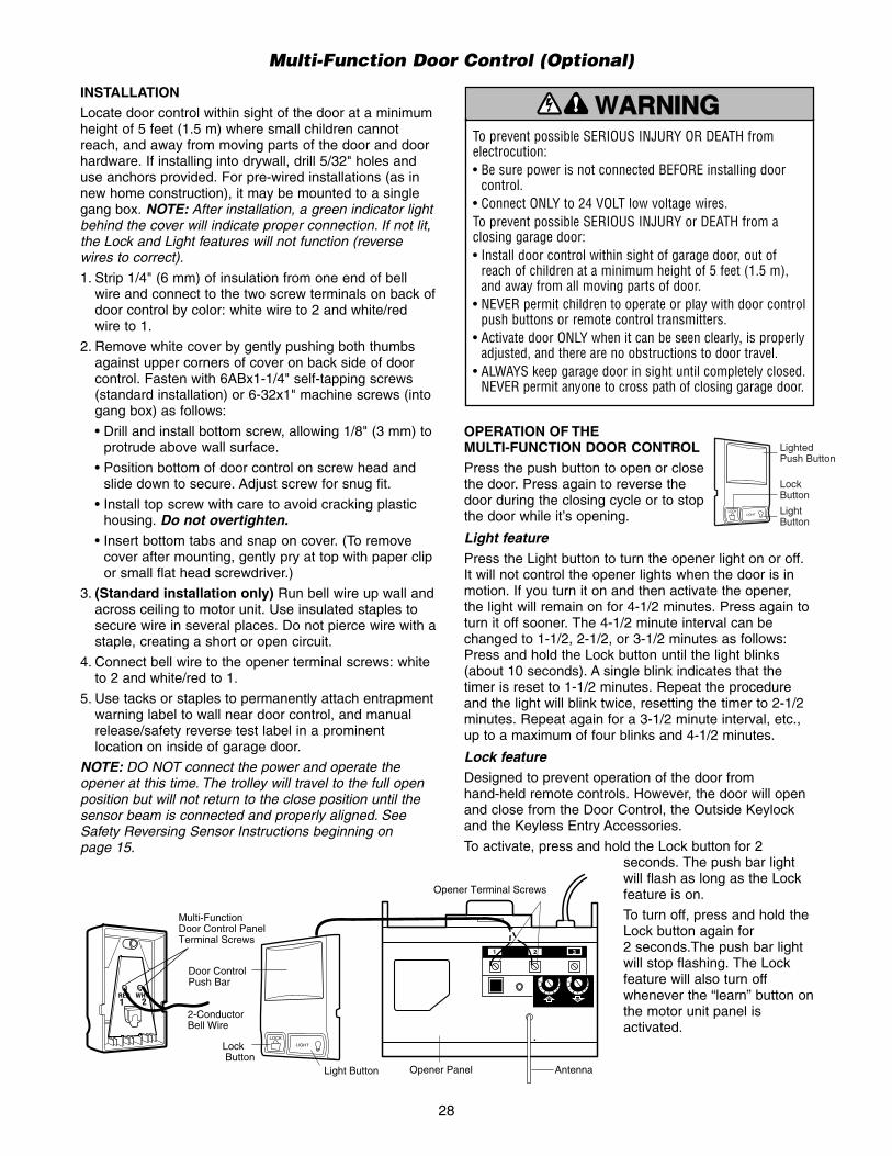
Multi-Function Door Control (Optional)
OPERATION OF THE MULTI-FUNCTION DOOR CONTROLPress the push button to open or closethe door. Press again to reverse thedoor during the closing cycle or to stopthe door while it’s opening.
Light featurePress the Light button to turn the opener light on or off.It will not control the opener lights when the door is inmotion. If you turn it on and then activate the opener,the light will remain on for 4-1/2 minutes. Press again toturn it off sooner. The 4-1/2 minute interval can bechanged to 1-1/2, 2-1/2, or 3-1/2 minutes as follows:Press and hold the Lock button until the light blinks(about 10 seconds). A single blink indicates that thetimer is reset to 1-1/2 minutes. Repeat the procedureand the light will blink twice, resetting the timer to 2-1/2minutes. Repeat again for a 3-1/2 minute interval, etc.,up to a maximum of four blinks and 4-1/2 minutes.
Lock featureDesigned to prevent operation of the door from hand-held remote controls. However, the door will openand close from the Door Control, the Outside Keylockand the Keyless Entry Accessories.
To activate, press and hold the Lock button for 2seconds. The push bar lightwill flash as long as the Lockfeature is on.
To turn off, press and hold theLock button again for2 seconds.The push bar lightwill stop flashing. The Lockfeature will also turn offwhenever the “learn” button onthe motor unit panel isactivated.
LOCKLIGHT
LightedPush Button
Lock Button
LightButton
To prevent possible SERIOUS INJURY OR DEATH fromelectrocution:• Be sure power is not connected BEFORE installing door
control.• Connect ONLY to 24 VOLT low voltage wires. To prevent possible SERIOUS INJURY or DEATH from aclosing garage door:• Install door control within sight of garage door, out of
reach of children at a minimum height of 5 feet (1.5 m),and away from all moving parts of door.
• NEVER permit children to operate or play with door controlpush buttons or remote control transmitters.
• Activate door ONLY when it can be seen clearly, is properlyadjusted, and there are no obstructions to door travel.
• ALWAYS keep garage door in sight until completely closed.NEVER permit anyone to cross path of closing garage door.
WARNING
CAUTION WARNARNINGING
WARNING
Opener Terminal Screws
2-ConductorBell Wire
AntennaOpener Panel
Multi-FunctionDoor Control PanelTerminal Screws
KG KG
1
3
9
7
5
1
3
9
7
5
1 2 3
Door ControlPush Bar
Light Button
Lock Button
LOCK
LIGHT
21RED WHT
INSTALLATIONLocate door control within sight of the door at a minimumheight of 5 feet (1.5 m) where small children cannotreach, and away from moving parts of the door and doorhardware. If installing into drywall, drill 5/32" holes anduse anchors provided. For pre-wired installations (as innew home construction), it may be mounted to a singlegang box. NOTE: After installation, a green indicator lightbehind the cover will indicate proper connection. If not lit,the Lock and Light features will not function (reversewires to correct).
1. Strip 1/4" (6 mm) of insulation from one end of bellwire and connect to the two screw terminals on back ofdoor control by color: white wire to 2 and white/red wire to 1.
2. Remove white cover by gently pushing both thumbsagainst upper corners of cover on back side of doorcontrol. Fasten with 6ABx1-1/4" self-tapping screws(standard installation) or 6-32x1" machine screws (intogang box) as follows:
• Drill and install bottom screw, allowing 1/8" (3 mm) toprotrude above wall surface.
• Position bottom of door control on screw head andslide down to secure. Adjust screw for snug fit.
• Install top screw with care to avoid cracking plastichousing. Do not overtighten.
• Insert bottom tabs and snap on cover. (To removecover after mounting, gently pry at top with paper clipor small flat head screwdriver.)
3. (Standard installation only) Run bell wire up wall andacross ceiling to motor unit. Use insulated staples tosecure wire in several places. Do not pierce wire with astaple, creating a short or open circuit.
4. Connect bell wire to the opener terminal screws: whiteto 2 and white/red to 1.
5. Use tacks or staples to permanently attach entrapmentwarning label to wall near door control, and manualrelease/safety reverse test label in a prominentlocation on inside of garage door.
NOTE: DO NOT connect the power and operate theopener at this time. The trolley will travel to the full openposition but will not return to the close position until thesensor beam is connected and properly aligned. SeeSafety Reversing Sensor Instructions beginning on page 15.

29
6UP
CEILING MOUNT ONLY
10
1NOTICE
3
5
4
9
8
11 12
2
7
2
1
3
4
5
Installation Parts
REPAIR PARTS
Rail Assembly Parts
KEY PARTNO. NO. DESCRIPTION
1 4A1008 Master link kit2 41A2780 Chain pulley bracket3 41A3489 Complete trolley assembly4 CD1008 8 Foot (2.4 m) Rail Assembly
CD1010 10 Foot (3 m) Rail AssemblyCD1012 12 Foot (3.7 m) Rail AssemblyCD1014 14 Foot (4.3 m) Rail Assembly
5 83A12 Rail greaseNOT SHOWN
6 41C771 Center Bracket (1 pce.)
KEY PARTNO. NO. DESCRIPTION
1 41A4166 Door control push button2 41B4494-1 2-conductor bell wire, white &
white/red3 41A2828 Emergency release rope &
handle assembly4 12B374 Door bracket5 12B380 Door bracket plate6 41A4353 Header bracket w/clevis pin & fastener7 41A4373A Safety sensor kit
(receiving and sending eyes) with3' (.9 m) 2-conductor bell wire attached
8 178B35 Curved door arm section9 12B483 C Wrap bracket
10 178B34 Straight door arm section178B73 Straight door arm section (14' door)
11 12B484 Square hole mounting bracket12 12B485 Slotted mounting bracket
NOT SHOWN41A2770 Installation hardware bag (page 5).41A4116 Safety sensor hardware114A2995 Owner’s manual114A2995SP Owner’s manual - Spanish

30
Motor Unit Assembly Parts
9
7
12
13
1415
18
4
8
11
17
10
16
3
5 6
1815
DN
UP
BrownWire
(Down)Contact
LIMIT SWITCH ASSY.
GreyWire
YellowWire
(Up)Contact
Center LimitContact
DriveGear
1
2
KEY PARTNO. NO. DESCRIPTION
1 41C5069 Rail support bracket assembly kit2 41B4569 Pulley (Chain)3 41A5668 Gear and sprocket assembly.
Complete with:Spring washer, thrust washer,retaining washer, bearing plateroll pins (2), drive gear and worm gear, helical gear w/retainer and grease,sprocket shaft plate with screws
4 41A2817 Drive/worm gear kit w/greaseRoll pins (2)
5 143D100-1 Front end panel6 4A1344 Light socket7 30B432 Capacitor8 12A461 Capacitor bracket9 41A3150 Terminal block with screws
KEY PARTNO. NO. DESCRIPTION
10 41D4509 Replacement motor & bracketassemblyComplete with: Motor, worm,bracket, bearing assembly
11 41A4593-4 Cover12 81C253 Helical gear & retainer w/grease13 41A5640 Limit switch assembly14 41C4398A RPM sensor assembly15 41C4246 Wire harness assembly w/plug16 41A2826 Shaft bearing kit17 41A2822A Interrupter cup assembly18 41A5021-1GATS Receiver logic board assembly
Complete with: Logic board,end panel with all labelsNOT SHOWN
41A2825 Opener assembly hardware kit(includes screws not designatedby a number in illustration).

31
ACCESSORIES
LOCKLIGHT
970LMCD1008
1702LM Outside Quick Release:Required for a garage with NOaccess door. Enableshomeowner to open garage doormanually from outside bydisengaging trolley.
8 Foot (2.4 m) Complete Rail:To allow an 8 foot (2.4 m) doorto open fully.
10 Foot (3 m) Complete Rail:To allow a 10 foot (3 m) door toopen fully.
Multi-Function Door Control Panel:Provides a Lock Feature whichprevents operation of garage dooropener from portable remotes and aLight Feature for constant light.
CD1010
976LG
972RGD
971RGD
973RGD180C139
SECURITY✚® Keyless Entry:Enables homeowner to operate garagedoor opener from outside by entering apassword on a specially designedkeyboard. Also can add a temporarypassword for visitors or servicepersons. This temporary password canbe limited to a programmable numberof hours or entries.
78LM
12 Foot (3.7 m) Complete Rail:To allow a 12 foot (3.7 m) doorto open fully.
CD1012
14 Foot (4.3 m) Complete Rail:To allow a 14 foot (4.3 m) doorto open fully.
CD1014
Light Lens Cover:Attractive lens cover protectslight bulbs and diffuses light toevery corner of your garage.
108D36
59LM
NEMA 1 Push Button:Heavy Duty Door Control PushButton (one button).
Outside Keylock:Opens the garage doorautomatically from outside whenremote control is not handy.
50111 Center Bracket (6 pces.):Adds additional stability to a rail byenabling the use of additional hangingbrackets if desired.
SAFETY SIGNALTM 1-Button Remote Control:
Includes visor clip.
SAFETY SIGNALTM 3-ButtonRemote Control:
Includes visor clip.
SAFETY SIGNALTM 2-ButtonRemote Control:
Includes visor clip.
3-Button Mini-Remote Control with SECURITY✚®:
With key ring and fastening strip.

©2006, Raynor Garage Doors114A2995B All Rights Reserved
RAYNOR SERVICE IS ONCALL
OUR LARGE SERVICE ORGANIZATIONSPANS AMERICA
INSTALLATION AND SERVICE INFORMATION IS ASNEAR AS YOUR TELEPHONE SIMPLY DIAL OUR TOLL
FREE NUMBER:
1-800-472-9667HOURS: (Central Std. Time)
7:00 A.M. TO 6:00 P.M. - Monday through Friday
www.raynor.com
For professional installation, parts and service,contact your local RAYNOR GARAGE DOORDISTRIBUTOR. Look for him in the Yellow Pages, orvisit our Dealer Locator on our Website
HOW TO ORDERREPAIR PARTS
Selling prices will be furnished on request or parts will be shipped at prevailing prices and you will be
billed accordingly.
WHEN ORDERING REPAIR PARTS, ALWAYS GIVETHE FOLLOWING INFORMATION:
• PART NUMBER
• PART NAME
• MODEL NUMBER
ADDRESS ORDERS TO:RAYNOR GARAGE DOORS
Technical Support Group6020 S. Country Club Road
Tucson, Arizona 85706
SERVICE INFORMATIONTOLL FREE NUMBER:
1-888-528-6306
RAYNOR ONE YEAR LIMITED WARRANTYLIFETIME MOTOR LIMITED WARRANTY
Raynor (“Seller”) warrants to the first retail purchaser of this product, for the residence in which this product is originallyinstalled, that it is free from defect in materials and/or workmanship for a period of one year from the date of purchase [and thatthe motor is free from defect in materials and/or workmanship for the lifetime of the product]. The proper operation of thisproduct is dependent on your compliance with the instructions regarding installation, operation, maintenance and testing.Failure to comply strictly with those instructions will void this limited warranty in its entirety.
If, during the limited warranty period, this product appears to contain a defect covered by this limited warranty, call 1-888-528-6306, toll free, before dismantling this product. Then send this product, pre-paid and insured, to our service center for warrantyrepair. You will be advised of shipping instructions when you call. Please include a brief description of the problem and a datedproof-of-purchase receipt with any product returned for warranty repair. Products returned to Seller for warranty repair, whichupon receipt by Seller are confirmed to be defective and covered by this limited warranty, will be repaired or replaced (at Seller’ssole option) at no cost to you and returned pre-paid. Defective parts will be repaired or replaced with new or factory-rebuilt partsat Seller’s sole option.
ALL IMPLIED WARRANTIES FOR THE PRODUCT, INCLUDING BUT NOT LIMITED TO ANY IMPLIED WARRANTIES OFMERCHANTABILITY AND FITNESS FOR A PARTICULAR PURPOSE, ARE LIMITED IN DURATION TO THE ONE YEARLIMITED WARRANTY PERIOD SET FORTH ABOVE [EXCEPT THE IMPLIED WARRANTIES WITH RESPECT TO THEMOTOR, WHICH ARE LIMITED IN DURATION TO THE LIFETIME LIMITED WARRANTY PERIOD FOR THE MOTOR], ANDNO IMPLIED WARRANTIES WILL EXIST OR APPLY AFTER SUCH PERIOD. Some States do not allow limitations on howlong an implied warranty lasts, so the above limitation may not apply to you. THIS LIMITED WARRANTY DOES NOTCOVER NON-DEFECT DAMAGE, DAMAGE CAUSED BY IMPROPER INSTALLATION, OPERATION OR CARE(INCLUDING, BUT NOT LIMITED TO ABUSE, MISUSE, FAILURE TO PROVIDE REASONABLE AND NECESSARYMAINTENANCE, UNAUTHORIZED REPAIRS OR ANY ALTERATIONS TO THIS PRODUCT), LABOR CHARGES FORREINSTALLING A REPAIRED OR REPLACED UNIT, REPLACEMENT OF BATTERIES AND LIGHT BULBS OR UNITSINSTALLED FOR NON-RESIDENTIAL USE.THIS LIMITED WARRANTY DOES NOT COVER ANY PROBLEMS WITH, OR RELATING TO, THE GARAGE DOOR ORGARAGE DOOR HARDWARE, INCLUDING BUT NOT LIMITED TO THE DOOR SPRINGS, DOOR ROLLERS, DOORALIGNMENT OR HINGES. THIS LIMITED WARRANTY ALSO DOES NOT COVER ANY PROBLEMS CAUSED BYINTERFERENCE. ANY SERVICE CALL THAT DETERMINES THE PROBLEM HAS BEEN CAUSED BY ANY OF THESEITEMS COULD RESULT IN A FEE TO YOU.UNDER NO CIRCUMSTANCES SHALL SELLER BE LIABLE FOR CONSEQUENTIAL, INCIDENTAL OR SPECIALDAMAGES ARISING IN CONNECTION WITH USE, OR INABILITY TO USE, THIS PRODUCT. IN NO EVENT SHALLSELLER’S LIABILITY FOR BREACH OF WARRANTY, BREACH OF CONTRACT, NEGLIGENCE OR STRICT LIABILITYEXCEED THE COST OF THE PRODUCT COVERED HEREBY. NO PERSON IS AUTHORIZED TO ASSUME FOR US ANYOTHER LIABILITY IN CONNECTION WITH THE SALE OF THIS PRODUCT.Some states do not allow the exclusion or limitation of consequential, incidental or special damages, so the above limitation orexclusion may not apply to you. This limited warranty gives you specific legal rights, and you may also have other rights whichvary from state to state.