commercial disposal of high integrity containers …
TRANSCRIPT

- --- - .---~.~-.---- -- - --- ...... - - -- ---- - . - --- - - ---.. - .. _._.
DISCLAIMER
This report was prepared as an account of work sponsored b" an agency of the United States . Government. Neither the United States Government nor any agency thereof, nor any of their employees, makes any warranty, express or implied, or assumes any legal liability or responsibility for the accuracy, completeness, or usefulness of any information, apparatus, product, or process disclOlCd, or represents that its use would not infringe privately owned rights. Reference herein to any specific commercial product, process, or service by trade name, trademark, manufacturer, or otherwise docs not necessarily constitute or imply its endorsement, recommendation, or favoring by the United States Government or any agency thereof. The views and opinions of authors expressed herein do not necessarily state or reflect those of the
United States GGvemmcnt or any agency thereof.
GEND-048 Distribution Category: UC-78
GEND--048
TI86 002545
COMMERCIAL DISPOSAL OF HIGH INTEGRITY CONTAINERS (HICs) CONTAINING EPICOR·II
PREFILTERS FROM THREE MILE ISLAND
John W. McConnell. Jr. R. Jon Lynch
Michael J. Tyacke
Published September 1985
EGI:'-G Idaho, Inc. Idaho I=alls, Idaho 83415
F'repared for the U.S. Department of Energy
Idaho Operation Office Under DOE Contract No. DE-AC07-76ID01570
DJSTRIBDIUl~ Of nus 08CUMINJ IS UHLlIOiiG

ABSTRACT
This report describes the processes of loading, transporting, and commercially disposing of 45 High Integrity Cmltainers (HICs), each containing an EPICOR-II prefilter. Also described are the improvements that were applied in the disposition of the 45 commercial EPICOR-II pre filters at the Idaho National Engineering Laboratory (INEL), versus those used for the demonstration unit. The significance of this effort was that the commercial disposal campaign involved the first-of-a-kind production use of a reinforced concrete HIC at the US Ecology, Inc. facility in the State of Washington. This allowed for safe disposal of high specific activity ion exchange material in EPICOR-II prefilters generated during the cleanup ofthe Unit-2 Auxiliary and Fuel Handling Building of the Three Mile Island Nuclear Power Station.
ii
I .: -, ~ . -, . l _.:v . ~ .' -. . 1'i .' f r"1 ". -' ~

SUMMARY
The cleanup of Three Mile Island Unit 2 (TMI-2) produced 50 EPICOR-II prefilters, containing dewatered, radioactive ion-exchange resins and zeolites. As part of the EPICOR-II Research and Disposition Program, EPICOR-II prefilters were transported to the INEL for research, interim storage, and disposal at the US Ecology site in the State of Washington. The program developed the first-of-a-kind reinforced concrete HIC approved for use by the State of Washington, and then used the first production model for disposing of an EPICOR-II prefilter in a disposal demonstration. Finally, 45 HICs containing EPICOR-II prefilters were disposed by employing the same techniques under a commercial agreement between GPU Nuclear Corp. (GPUN) and U.S. Ecology; four prefilters were retained for NRC resin research. This document presents information gained from the HIC commercial disposal campaign and related work leading to the successful completion of the disposal.
The commercial disposal was performed at the U,S. Ecology low-level radioactive waste disposal facility in the State of Washington. Obtaining approval for use of the HIC for disposing of EPICOR-II premters required applying to the State of Washington for approval and satisfying technical concerns raised by the State and the U.S. Nuclear Regulatory Commission. Successful completion of the EPICOR/HIC disposal was the result of nearly five years of intense effort that involved (a) obtaining approvals for transporting and disposing of the HIC loaded with an EPICOR-II premter, (b) designing and fabricating an HIC, (c) testing HICs, (d) developing a process for preparing the EPICOR-II premter and HIC for disposal, (e) acquiring required equipment for the project, and (f) completing an HIC disposal demonstration.
The process for preparing the EPICOR-II prefilters and HICs for disposal required developing procedures, training personnel, performing the actual process on a demonstration unit, and revising the procedures to correct difficiencies identified during the demonstration. Preparing the prefilters and HICs required designing and fabricating specialized equipment for remote use in the Hot Shop, located in the Test Area North (TI\N) Complex of INEL. Based on lessons learned from the disposal demonstration, some equipment was further modified to improve operation during the commercial disposal campaign.
It is concluded that the successful HIC commercial disposal campaign demonstrated that high integrity containers are an alternative to solidification of certain wastes for disposal.
iii
If-

CONTENTS
ABSTRACT ........................................................... ................ H
SUMMARY ........................................................................... iii
1. INTRODUCTION ............................................................... .
2. PERSPECTIVE .................................................................. .
3. HARDWARE AND FACILITIES .................................................... 3
3.1 EPICOR-II Prefilter ...................•...................................... 3
3.2 High Integrity Container. . . . . . . . . . . . . . . . . . . . . . . . . . . . . . . . . . . . . . . . . . . . . . . . . . . . . . . 4
3.3 Shipping Cask and Trailer. . . . . . . . . . . . . . . . . . . . . . . . . . . . . . . . . . . . . . . . . . . . . . . . . . . . . . 5
3.4 INEL Facility ................................................................ 5
3.5 Commercial Disposal Facility. . . . . . . . . . . . . . . . . . . . . . . . . . . . . . . . . . . . . . . . . . . . . . . . . . . 5
3.6 Support Equipment ........................................................... 7
3.7 Preparation Differences Between Disposal Campaign and Disposal Demonstration.. .. .. 7
3.7.1 Facility Upgrades................................. ...... ................ 7 3.7.2 Prefilter Preparations for Disposal ........................................ 7 3.7.3 HIC Preparations for Disposal ........................................... 10
4. REGULATORY APPROVAL PROCESS . . . . . . . . . . . . . . . . . . . . . . . . . . . . . . . . . . . . . . . . . . . . . . 13
5. HIC DISPOSAL CAMPAIGN ...................................................... 17
5.1 HIC Preparation ............................................................. 17
5.1.1 Procedural Changes . . . . . . . . . . . . . . . . . . . . . . . . . . . . . . . . . . . . . . . . . . . . . . . . . . . . . 17 5.1.2 HIC Receipt and Preparation....... .... .......... .... .. ........... ... .. .. 17 5.1.3 EPICOR-II Prefilter Preparation. . . . . . . . . . . . . . . . . . . . . . . . . . . . . . . . . . . . . . . . . . 17 5.1.4 HIC Loading and Curing............................................... 19 5.1.5 Shipping Cask PrepRration .... ........................................... 21
5.2 HIC Shipping and Disposal .................................................... 21
6. CONCLUSIONS. . . . . . . . . . . . . . . . . . . . . . . . . . . . . . . . . . . . . . . . . . . . . . . . . . . . . . . . . . . . . . . . . . 32
7. REFERENCES 32
FIGURES
I. Schematic of an EPICOR-II prefilte:r 3
2. Design configuration of the HIC without an enclosed EPICOR-II prefilter ................. 4
iv

3. Schematic of the tractor and trailer loaded with a shipping cask, HIC, and EPICOR-II prefilter for transport to the commercial disposal facility . . . . . . . . . . . . . . . . . . . . . . . . . . . . . . . . . 6
4. Schematic of the CNS 14-190 Type B shipping cask ........... : "' .. ", . ' .. ' .... , .... ',"" . . . 7
S. Floor plan and cross-sectional view of the TAN-607 Hot Shop ............................ 8
6. Schematic of the dewatering and purging equipment used to prepare PF-18 for loading intotheHIC ........................ !............................................. 9
7. Schematic of lid caulking stand ...................................................... 10
8. Grout cone and cup assembly . . . . . . . . . . . . . . . . . . . . . . . . . . . . . . . . . . . . . . . . . . . . . . . . . . . . . . . . 11
9. Photograph of the steel reinforced, concrete shielded temporary curing cask (a) and transfer/storage bell (b) . . . . . . . . . . . . . . . . . . . . . . . . . . . . . . . . . . . . . . . . . . . . . . . . . . . . . . . . . . . . . 12
10. Photograph of an EPICOR-II prefilter being lowered into the curing cask (arrow points to HIC spreader bar) ................................................... 14
11. Photograph of HIC lifting sling (arrow) ............................................... IS
12. Photograph of placement in trench of disposal demonstration of HIC with cribbing at commercial disposal site ............................................................ 15
13. Achievement network for development and use of EPICOR/HIC ......................... 16
14. lask flow for HIC disposal campaign....................................... .......... 18
15. Photograph of dewatered and purged prefilter being placed in the prepared HIC ............. 22
16. Phoiograph of technician applying primary sealant around outside diam.eter of the bottom of HIC lid .................................................................. 23
17. Photograph of grouting cone being placed on the HIC lid .......... , . . . . . . . . . . . . . . . . . . . . . 24
18. Photograph of epoxy concressive AEX-1512 grout being mixed outsid.e hot shop ............ 25
19. Photograph of grout being poured over the grouting cone into the lid-body annulus of the HIC ..................................................... ,................. 26
20. Photograph of trailer being disconnected from. tractor in hot shop. . . . . . . . . . . . . . . . . . . . . . . . . 27
21. Photograph of HIC being retrieved remotely from curing cask storage. The manipulator is being used to remove the protecdve plastic sheet ...................................... 28
22. Photograph of HIC being lowered remotely into shipping cask. . . . . . . . . . . . . . . . . . . . . . . . . . . . 29
23. Photograph of tractor, shipping cask, and trailer being moved. outsidf~ the hot shop .......... 30
24. Photograph of HIC being removed from the shipping cask at the U.S. ecology site. . . . . . . . . . . 30
25. Photograph of HIC being lowered into disposal trench at US. ecology site ................. 31
26. Photograph of HIC being covered with soil using a clam-shell equipped crane. . . . . . . . . . . . . . . 31
v

TABLE
1. EPICOR/HIC loading and shipping data ............................................. 19
vi

COMMERCIAL DISPOSAL OF HIGH INTEGRITY CONTAINERS (HICs) CONTAINING EPICOR-II
PREFILTERS FROM THREE MILE ISLAND
1. INTRODUCTION
A first-of-a-kind, high integrity container (HIC) has been developed, tested, and subsequently approved by the State of Washington for use in disposing of EPICOR-II prefilters that were employed in processing about 2}00 m3 (560,000 gall of accident-generated contaminated water from the Auxiliary and Fuel Handling Buildings of Unit 2 of Three Mile Island (TMI-2). Fifty of those prefilters were transported to the Idaho National Engineering Laboratory (lNEL) for interim storage, research, and disposition. The successful disposal demonstration of one EPICOR-II prefilter contained in an HIC paved the way for GPUN to dispose of 45 additional prefilters in HICs at the waste disposal facility operated by US Ecology, Inc. -in the State of Washington. [Disposal of four prefilters still being used in rese~rch will be accomplished later.]
Each EPICOR-II prefilter contained up to 2200 Ci of radioactive isotopes. In order to meet the 10 CFR 61 criteria for disposal as Class C lowlevel radioactive waste, either (a) the ion exchange media of the prefilter had to be solidified or (b) the prefilter had to be enclosed in an HIC before disposal.} A reinforced concrete HIC was chosen over solidification, after studies projected that the HIC would be cost-effective for the disposal of the unusual EPICOR-ll prefilter wastes. [This projc.c-
tion was reaffirmed after the disposal demonstration.2] There were four major undertakings which, when accomplished, allowed the commercial disposal to take place. These were:
• Developing the first-of-a-kind reinforced concrete HIC
• Locating/fabricating a suitable shipping cask3
• Receiving regulatory approval for use of the HIC in a disposal demonstration
• Effecting the disposal demonstration of that HIC with a prefilter.
Objectives of the EPICOR-ll Research and Disposition Program include development of an HIC system and disposal of the 50 EPICOR-II prefilters in HICs. In order to complete those objectives, a suitable HIC was specified, designed, fabricated, tested, and used in a disposal demonstration operation. That HIC system was then used to commercially dispose of 45 EPICOR-II prefilters. This document presents a brief description of processes, equipment, and facilities used in the disposal of the EPICOR-II prefilters sealed in HICs.
2. PERSPECTIVE
The TMI-2 accident on 28 March 197~ nrovided an opportunity for both the nuclear industry and federal government to benefit from evaluating how the accident happened, determining the effects of the accident, and the development of procedures to clean up such an accident. The Department of Energy (DOE) was given the responsibility for conducting research and development activities of generic value to the nuclear industry.4,5 One DOE program d(~eloped to accomplish that responsibility was the Waste Immobilization Program (WIP).6 Objectives of WIP included evaluating existing technologies/techniques or developing new methods to implement safe, c:ost-
effective handling, transportation, interim storage, and disposal of highly radioactive ion exchange media (as exemplified by the EPICOR-II ion exchange wastes) as well as transferring information of generic benefit to the nuclear industry. On 15 July 1981, a Memo!'andum of Understanding between DOE and the U.S. Nuclear Regulatory Commission (NRC) was signed whereby DOE agreed to accept 50 EPICOR-II premters for research, interim storage, and disposition. On 1 October 1982 EG&G Idaho and GPUN signed Thsk Order No. 113 for the shipment, processing, and disposal of those premters.

The EPICOR~II Research and Disposition Program (later renamed the EPICOR and Waste Research and Disposition Program) was conducted by EG&G Idaho, Inc. to satisfy part of the WIP objectives.6 The overall goal of the EPICOR-II Research and Disposition Program was to perform resea;~h cf generic value to the nuclear industry and safely dispose of the 50 EPICOR-II pre filters as Class C low-Ievei waste. The EPICOR/HIC commercial disposal of 45 EPICOR pre filters was one activity undertaken to meet that goal. The disposal of those EPICOR pre filters in HICs has assisted materially in the cleanup of TMI-2, and has provided a long-term safe disposal method for the high specific activity ;on exchange material contained therein.
Successful completion of the EPICOR/HIC disposal campaign required the participation of many organizations. EG&G Idaho had the administrative and technical responsibility of developing and testing the HIC, acquiring regulatory approvals, and demonstrating commercial disposal ofthe HIC loaded with an EPICOR-II prefilter. GPUN supported the disposal of 45 additional prefilters in a manner similar to the successful demonstration. 7
The following were performed under subcontract to EG&G Idaho: Sandia National Laboratories developed specifications for an HIC; Nuclear Packaging, Inc. (NuPac) designed the HIC, presented a design review, built two prototype HICs, and tested one unit; and US Ecology provided the disposal service for the demonstration and the commercial campaign. Also under subcontract, US Ecology prepared and submitted an HIC Use Application to the State of Washington Department of Social and Health Services. The State, with support from NRC, commented on the HIC desigH and reviewed the disposal program. Those comments were resolved, and a Certification of Compliance from the State of Washington was issued to US Ecology for disposal of the 50 EPICOR-II prefilters using the HIC designed by NuPac. a
The activity funding breakdown resulting from the agreement between EG&G Idaho and GPUN follows.
a. To avoid confusing the reader, it is noted that the Hie Use Application to the State of Washington cited in this report resulted in a Certification of Compliance being issued by the State for use of the HIC in burial operations.
2
A. GPUN Funded Activities-(all tasks relating to disposal)
1. Procuring and shipping of High Integrity Container (HIC) to the INEL.b
2. Shipping of 50 EPICOR prefilters from TMI to INEL for processing.
3. Dewatering and checking of pH on 45 prefilters.
4. Loading 45 prefilters into HICs and sealing of HICs.
5. Payment for use of shipping cask.
6. Shipping of 45 HICs containing EPICOR pre filters to commercial disposal site. DOE/EG&G functioned as shipper of record.
7. Disposal of 45 HICs at commercial burial site.
B. DOE Funded Activities
1. All activities and associated costs for procurement of an HIC. Licensing and burial of a prototype EPICOR-I1 prefilter in an HIC (to demonstrate "best effort basis" performance by EG&G) at a reasonab1e total cost, so that GPUN could entt!r into contract to fund remaining prefilter disposal operations.
2. Interim storage.
3. Storage silo/temporary storage cask (TSC) unloading.
4. Purging of combustible gases from 45 EPICOR prefilters.
5. Research at INEL.
6. Shipping cask preparations and loading of 45 HICs for shipment to commercial disposal site.
b. Task manageu directly by GPUN. All others managed through EG&G Idaho.

t l t
3. HARDWARE AND FACILITIES
This section briefly describes the EPICOR-II prefilter, HIC, shipping cask and trailer, INEL facility used for storing EPICOR-II prefilters, support equipment used for the disposal process, and the disposal facility where the HIes were disposed. Consult Reference 7 for further detail.
3.1 EPICOR-II Prefilter
Each EPICOR-II prefilter liner is a cylinder 1.2 m (48 in.) in diameter by 1.4-m (54-in.) high, fabricated from 6.4-mm (1I4-in.) welded steel (Figure I). Each liner contains ",850 m3 (30 ft3) of ion exchange media which are either organic resins or organic resins and zeolite absorbers. An inlet header system was used to spread unprocessecl water over the top of the ion exchange media, while an outlet header system collected water processed through the ion exchange media. Each liuer is coated inside and out with Phenoline 368a paint to
a. Phenoline 368 is a product of the Carboline Co.
O.l06·m (4·in.) connection in lid
------- 1.25·mOD -f-=-:---:-::------I (49.in.) 13101Smm
(0.5 10 0.63 in.)
protect it against corrosion. Metallurgical examination of two prefilter liners, performed as part of the EPICOR-II Research and Disposition Program, has shown that the estimated life of the liners before failure by corrosion is greater than 50 years.8 An EPICOR-II liner weighs 635 kg (1400 lb) empty and ",1542 kg (3400 lb) when loaded with resin. Resin loadings range from 585 kg (1290 Ib) to 880 kg (1940 lb).
In processing water from the Auxiliary and Fuel Handling Buildings of TMI, each prefilter collected radionuclides consisting mostly of Cs-137, -134, and their daughter products; small amounts of Ru-I06, Rh-I06, Sr-90, Co-60, and Ba-137; and trace amounts of U-238 and some transuranic elements. Hydrogen gas is generated in the pre filters from radiolytic degradation of demineralizer materials and radiolysis of water. 9 To prevent buildup of that gas, a plug was removed remotely from the vent port of each prefilter upon arrival at INEL. Removal of the vent plug aHowed the gas to exit continuously from the prefilter during storage. The
------
INEL 4 0665
Figure l. Schematic of an EPICOR-II prefilter.
3

gas was collected and routed to the ventilation system of the storage facility.
3.2 High Integrity Container
The HIC is a reinforced concrete cylindrical container designed for disposal of an EPICOR-II prefilter at a commercial disposal facility for low-level radioactive waste. I 0,11,12 The container is designed to ensure safe, reliable, below ground disposal of radioactive waste for a minimum of
Grouted epoxy seal concresive 1512/1513
1.56m (61.5 in.)
Amphoteric paste AI(OH)3 (four locations In bottom)
• L
..
... ..
300 years <",10 half-lives of the predominant isotopes) while radioactive isotopes contained in the resins decay to a nonhazardous level.
Figure 2 illustrates the design configuration of the HIC. Leakage is prevented by a corrosionresistant steel liner which is coated inside and out with phenolic paint. Durability of the HIC is enhanced by the pH-adjusting amphoteric material placed on the inside bottom of the HIC. After loading, the HIC lid is sealed and then bonded to the HIC body using a bead of adhesive gel Concressive
,.
I 2.13m
• (84 in.) .. I
...... .. . .. .. .. ..... "
Lid lift inserts
C(,lltainer lift eyes
Vent system
Sulfate-resistant (Type V) concrete
Rebar cage
Shear studs
Phenolic-coated, 6.4-mm (1/4-in.) steel
Polyethylene abrasion liner
---1.26 ITI-----I (49.5 in.)
INEl 4 0666
Figure 2. Design configuration of the HIC without an enclosed EPICOR-II prefilter.
4

AEX-1513 and flowable grout material Concressive AEX-1512, respectively. a The HIC is equipped with a vent system to allow the escape of gas produced by radiolysis in the EPICOR-II prefilter. [The EPICOR-II prefilter is purged with argon gas before being loaded into the HIC.] The vent is cast into, and protected by, the reinforced concrete lid assembly. Without venting, the HIC has sufficient burst strength to contain the gas that may be generated, based on a 300-year life. The concrete container attenuates radiation from the enclosed EPICOR-II prefilter by a factor of about nine; that is not er..ough shielding to permit hands-on operation but enough to simplify handling procedures and safety precautions. Reference 7, provides a detailed description of the HIC, and gives an evaluation of the HIC when transported and contained within the CNS 14-190 shipping cask.
3.3 Shipping Cask and Trailer
A certified 'TYpe B shipping cask, CNS 14-190, was used to contain the HICs with the prefilters during transport by truck from INEL to the disposal facility in the State of Washington (Reference 3). Figure 3 illustrates the tractor, trailer, and shipping cask loaded with the HIC and EPICOR-II prefilter. Figure 4 also shows the cribbing which was placed between the HIC and cask to prevent shifting of the HIC during transport. The cask was purchased from Chern Nuclear Systems, Inc. by DOE specifically for the task of transporting the 46 prefilters to the commercial disposal facility.
CNS 14-190 is a steel-encased, concrete-shielded blltpping cask. The cask is 2.39 m (94.25 in.) in di~lmeter by 2.64-m (l03.75-in.) long. Reinforced concrete occupies the I7.8-cm (7-in.) annular space between two shells and base plates. The lid is a I2.I-cm (4.75-in.) thick, laminated steel cover held in place by 32 high-strength, 3.18-cm (I-l/4-in.)diameter bolts. A silicone O-ring is used to seal the joint between the lid and the cask body. The outer shell and base plate are 6.4-cm (I-In-in.) thkk, while the inner shell and base plate are 5.I-em (2-in.) thick. The cask is reinforced at the top and bottom with steel rings and equipped with lifting lugs. The lid is provided with two access ports.
a. Concressive AEX-ISI2 and AEX-lS13 are products of Adhesive Engineering Company.
5
Empty weight of the cask is ",24,500 kg (54,000 Ib); the maximum payload of the cask is 10,400 kg (23,000 Ib).
The trailer also was purchased by DOE specifically for use with the shipping cask. It is a three axle, fifth wheel low-boy with a 36,300-kg (80,OOO-ib) capacity. The cask is held to the trailer by sixteen 3.i8-cm (l-l/4-in.) bolts. The empty weight of the cask, trailer, and tractor is ",39,500 kg (87,000 I"'), and the loaded weight (with H!C) is '\.46,700 kg (109,000 lb).
3.4 INEl Facility
The Hot Shop of Test Area North Building 607 (TAN-607) at INEL was used for the EPICOR-II Program because that facility was capable of receiving, handling, and storing EPICOR-II prefilters. The TAN-607 Hot Shop is a large, shielded high bay with rail and truck access through two 327,OOO-kg (360-ton) concrete doors, each 1.2-m (4-ft) thick by 4.3-m (14-ft) wide by IO.I-m (33-ft) high, with staggered joints and mounted on rollers. The Hot Shop is equipped with two overhead cranes (100 ton and IO ton) on a rolling crane bridge, a large overhead manipulator (located on a second rolling bridge), auxiliary wall-mounted manipulators, and other equipment for remote handling of radioactive material (Figure 5). The walls of the Hot Shop are constructed of concrete 2.I-m (7-ft) thick with shielded viewing windows built into the north and south walls. Operating galleries, located behind each shielded window, allow control of remotely operated equipment anywhere in the Hot Shop.
3.5 Commercial Disposal Facility
The HICs were disposed of at the Low-Level Radioactive Waste Disposal Facility in Benton County, Washington. The facility is located on the Hanford Nuclear Reservation, 25 miles northwest of Richland. Th(' State of Washington, unde~ the guidance of the NRC, regulates the disposal facility, which is operated by US Ecology. The types of w· ,tes authorized for receipt, and methods of handl.ng, transportation, and disposal all are subject to regulatory approval. Among the Il)w-level radioactive wastes disposed at the site are solid or sulidified materials, contaminated equipment, cleaning wastes, tools, protective clothing, gloves, and laboratory wastes. The contaminated materials are

0'1
Figure 3.
Transport cask - • r Cask raincover
Cribbing ~
Void space . .. 51 !lM-i High integrity
containe~ m I prefilter ....... =. ~ EPICOR II _
INEL40883
Schematic of the tractor and trailer loaded with a shipping cask, HIC, and EPICOR-II prefilter for tran~port to the commercial disposal facility.

_r,r..,,,,, I,
Side vieW
-~~-~~-·r_;
- r" ,1
,J /~
83
~I_L..
in.
1/2 In. x 1-1/2 in. steel bar, 72 in. 00 (top and bottom)
~-----------72in.----------~~
Diameter 52473
Figure 4. Schematic of the eNS 14-190 'tYPe B shipping cask.
received from hospit.als, laboratories, universities, industry, and nuclear power facilities.
The average disposal trench is about 46-m (150-ft) wide by 14-m (45-ft) deep by 244-m (800-ft) long. Filled trenches are marked with permanent monuments which describe the contents, boundaries, dates of use, and other pertinent information. Several locations on the site and in the surrounding area a;:-e monitored environmentally.
3.6 Support Equipment
Prep3ration of the EPICOR-II I·:efilters and HICs in the Hot Shop of TAN-607 required c;pecially designed equipment that could be used remotely. That equipment included: (a) liner lifting device (fbar) for lifting the prefilter; (b) venting tool for removing the lower distribution port plug from the prefilter; (c) dewatering and purging equipment for removing water and g? s from the prefilter; (d) HIe spreader bar for liftir I. the HIC; (e) lid lifting assembly for lifting the HIC lid; (f) liner interface colblr for protecting the HIC and guiding the prefilter into the HIC; (g) grouting equipment (cone and pouring cup) for attaching the HIe lid to the HIC body; (h) HIC lid caulking stand used to support the lid
7
while caulk is applied to the underside; (i) curing cask for shielding the HIC while grout cures; and G) transfer bell from Battel Columbus Laboratories (BCL) for shielding the prefilter during dewatering and purging operations.
3.7 Preparation Differences Between Disposal Campaign and Disposal Delnonstration
Upon completion of the demonstration prefilter disposal, a review was conducted which included viewing of video tapes of all operations. From that review came recommendations for modifications to equipment that enhanced the productivity of the commercial disposal campaign. Those improvement:; are described below.
3.7.1 Facility Upgrades. EG&G Idaho improved support equipment used in the Hot Shop where EPICOR-II pre filters were processed for disposal,
. induding refurbishing three wall-mounted manipulators and the overhead manipulator (O-man).
3.7.2 Prefilter Preparations for Disposal. Before an EPICOR-II prefilter was sealed in an HIC, it

~illrack.
Raised platform
L-J South equipment gallery
access -~~~=:1:::!~!======::il:l Icbyrlnth
Change room
, "'---
N t
Blparting lead·filled shield door.
Change mom access door ?
INEL 4 0662
Figure 5. Floor plan and cross-sectional view of the TAN-607 Hot Shop.
was dewatered and purged to meet transportation and disposal requirements of 10 CFR 61. Dewatering involved removing water from the lower (effluent) port of the prefilter, using a vacuum pump, and transferring that water to a 55-gallon drum for analysis and disposal. The prefilter was purged also, using compressed argon (through a vent port adapter) to remove any combustible gaHes generated by radiolysis. The remotely operated dewatering/purging system (Figure 6) was redesigned and modified to shorten the time reqL!ired to
8
perform each function. The major changes are described below;
• Dewatering/Purging Adapters-The dewatering and purging adapters were redesigned to prevent kinking of their respective hoses (thus impeding flow) and enable quick remote connection and disconnection of those hoses. During the "demonstration" program each operation required one hour to accomplish. After


modification those operations Wf'!'e accomplished in less than one hour total time.
• Argon System--A new flow meter was installed to allow a higher flow rate. A new regulator was installed which provided better flow control. A pressure relief valve was added to prevent inadvertant overpressurization of the liner. A new pressure gage with 1110 psi divisions was installed, permitting more accurate monitoring of pressure.
• Water Extraction Drum Assembly-A new drum assembly was designed and fabricated, eliminating the leaks that had been experienced in the original drum. The sight glass on the drum was lengthened to allow measuring of the water levels from gallery windows. As part of that modification, the drain was repositioned to provide for complete drum drainage. A mount for the vacuum line shutoff valve was added which provided easier remote operation of that valve.
3.7.3 Hie Preparations for Disposal. EG&G Idaho designed, redesigned, fabricated. and/or
4 in. typo r,; rt ~,in. I
I[i~========='--Y~-r
procured additional equipment which assisted in both manually or remotely processing of HICs for disposal. That equipment included a lid caulking stand, grouting cone and cup, temporary curing/ storage cask, BCL transfer/ storage bell, HIC spreader bar, HIC lifting slings, and cribbing for the CNS 14-190 shipping cask. The changes are described in more detail below.
• Lid Caulking Stand-A caulking stand (Figure 7) was designed and fabricated to enable manual application of the primary seal material to the bottom surface of the lid (cf Section 2).
• Grout Cone and Cup-A grout cone and cup (Figure 8) were designed and fabricated for pouring the secondary seal material using the O-man. The original tool, a three-legged funnel bracket (Reference 7), was not compatible with the remote operating equipment.
• Temporary Curing Cask-A steel reinforced concrete shielded cask was designed by EG&G and fabricated by AMCOR Inc. of Idaho Falls, idaho (Figure 9). The commercial HICs were placed in the cask for 8.
30 hour curing of the "primary" and
Spacer block 4 in. x 6 in. timber
66 in.
L-~ _________________________ ~~'_
... 1 ........ ----53 !n.----.... ,~ 52474
Figure 7. Schematic of lid caulking stand.
10

I !
Figure 8. Grout cone and cup assembly.
11

Figure 9. Photograph of the steel reinforced, concrete shielded temporary curing cask (A) and transfer/storage bell (8).
12

- ,
. :' i , ~ ~ - • • 'I j' .. _ ___ __
"secondary" seals between the lid and body. Use of the cask permitted personnel access to the Hot Shop during the curing period for other activities.
• BCL 'li'ansferlStorage Bell-A transferstorage device (Figure 9) was obtained from Battelle Columbus Laboratories which permitted processing two pre filters simultaneously.
The bell is a cylindrical lead-steel shield with removable top and bottom shield cover plates. The design of the device was based on shielding, with the objective of a maximum outer surface reading of ",50 mr/h with a prefilter installed. This allowed personnel access to the Hot Shop for other activities.
• HIC Spreader Bar-A spreader bar (Figure 10) was designed and fabricated which permitted lifting an HIC vertically without applying inward or outward stresses on the
'. HiC lifting eyes. The spreader bar, which featured a large crane hook eye and support rest, eliminated all two-device remote operations; that is, use of the madipulator to connect a sling or other equipment to a crane hook.
• HIC Lifting Slings-Lifting slings (Figure 11) were designed, procured, and permanently attached to an HIC before movement into the Hot Shop. The slings remained on the HIC for all processing and handling operations and for disposal at the commercial burial site. The design was novel in that the positioning of each sling was automatic across the HIC lid, and resulted in the slings being compressed by the cask lid during shipping. Upon removal of the cask lid the slings rise out of the cask for easy access by the disposal site lifting equipment.
• HIC-to-Shipping Cask Cribbing-The HIC-te-shipping cask cribbing (Figure 4), was used to fill the void between the inside diameter of the commercial CNS 14-190 shipping cask and the outside diameter of the HIC, preventing damage during transportation to the burial site. The cribbing was redesigned to allow fe-use for all ofthe 45 commercial HICs. The cribbing used in transporting the demon~t{at\oll unit became wedged to the HIC, resulting in both the HIC and cribbing being removed from the shipping cask and disposed of at the commercial disposal site (Figure 12).
4. REGULATORY APPROVAL PROCESS
One important outcome of the HIC work leading to the disposal demonstration was the achievement of regulatory approval for using this particular HIC. Approvals were required from regulatory authorities at a time when the regulatory position on HICs was not well established, criteria for HICs were still being developed, and the HIC concept was relatively untested. The regulation W CFR Part 61, "Licensing Requirements for Land Disposal of Radioactive Waste," 1 established a waste classification system based on radionuclide concentrations in the wastes. Class C wastes, like the EPJCOR prefilters, are required to be stabilized. Tii~ NRC Technical Position on Wllste Form gave guidance for stability (e.g., solidification or use of high integrity containers), along with criteria for high integrity containers. However, that techni~
13
cal position was formative at the start of the DOE effort described in this report.
The approval process for use of the HIC took approximately four years and involved the cooperation of federal and state governments, a public utility, and private industry working together for a common goal (discussed in detail in Reference 13). The process
. was a pathfinder; therefore, it is believed that much of the regulatory deliberation will be shortened for similar, future approval actions. Figure 13 presents a network for achievement of the goal to develop and use the EPICOR/HIC. Shown are paths of (a) requirements identification, (b) development/testing, (c) licensing, (d) fabrication, (e) research, and (f) transportation. The figure graphically illustrates the complexity involved in that approval process.

Figure 10. Photograph of an EPICOR-II prefilter being lowered into thl! curing cask (arrow points to HIC spreader bar).
14

Figure 11. Photograph of HIC lifting sling (arrow).
Figure 12. Photograph of placement in trench olr disposal demonstration of HIC with cribbing at commercial disposal site.
15

-0'1
Concurrence
" " r', I I I I I I I I L. _____ _
This figure Is adapted from a PQ,ter entitled, "Experiences In Use of Concrete High-Integrity Containers," by R.C. Schmitt and H.W. Reno, exhibited at Waste Management '85, Tucson, AZ, 24·28 March 1985.
Re .. arch
INEL
EG&G Idaho
C~ OrganIzation o Evenl
DHardwar~
0-""'" Figure 13. Achievement network for development and use of EPICOR/HIC.
52471

5. Hie DISPOSAL CAMPAIGN
The HIC disposal campaign was divided into the following two activities: (a) HIC preparation and (b) HIC shipping and disposal. Preparation of the HICs involved: receiving the empty HICs from the manufacturer, preparing and moving them into the Hot Shop of TAN-607, retrieving EPICOR-H prefilters from a silo or a temporary storage cask, preparing and loading the prefilters into the HICs, bonding (grouting) the lids onto the HICs, curing the bonding agent, and loading the HICs into the shipping cask. That task flow is shown diagramatically in Figure 14. HIC shipping and disposal involved preparing the shipping cask for transport, transporting the cask to the disposal facility, and disposing of the HICs. The following sections provide brief descriptions of the HIC disposal processes, as well as descriptions of the procedural changes which were made after the HIC demonstration task to improve productivity of the operation.
5.1 Hie Preparation
5.1.1 Procedli.iil Changes. Changes in Detailed Operating Procedures (OOPs) were a result of (a) the learning process from the demonstration task, and (b) equipment modifications/additions incorporated before commencement of the commercial campaign. The changes are described below.
A. The incorporation of the curing cask and the BCL transfer bell (cf Section I) allowed in-series processing of two prefilters by providing shielding for both prefilters. That change resulted in extensive procedure changes which in turn improved the productivity of prefilter processing by a factor of 2 for the commercial program.
B. The requirement to dispose of the water collected in the extraction drum assembly after each dewatering cycle was deleted. The drum was filled to its capacity before remotely emptying. This change was a result of the small quantities of wSlter removed on each demonstration unit dt.watering cycle (i.e., three cycles with a total estimate of between 5-15 gallons of water extracted) and the improvement of the sight glass on the water extraction <.trum (cf Section 3.7).
17
C. The method of application r f the epoxy gel primary seal material was ,~hanged.
Rather than applying the gel on the inside diameter lip of the HIC body, it wa~ applied to the underside of the lid. The work was done ill an area removed from the HIC. This change shortened the task performance time by a factor of 2 and moved the operation to a lower indication zone of the Hot Shop.
D. The curing time for the grout was shortened from 48 to 30 hours because the grout reached the strength of the surrounding concrete after the shorter cure time.
5.1.2 Hie Receipt and Preparation. The HICs used for the disposal campaign were fabricated by NuPac. Upon receipt of the HICs, exterior surfaces of the bodies were covered with plastic sheets. The plastic protected the exterior surfaces of the HIC from contamination while in the Hot Shop. 1\\'0 slings were permanently attached to each HIC (one to each of the HIC lifting eyes). The HICs then were moved into the Hot Shop for loading.
5.1.3 EPICOR·II Prefilter Preparation. The prefilters were stored both outside the TAN-607 Hot Shop in temporary storage casks (TSCs) mounted on railroad flatcars or in one of two silos within the Hot Shop (Figure 5). The flatcars were moved into the Hot Shop, where the prefilters were removed from the TSCs or the silo lids were removed and the prefilters lifted out. 1\\'0 prefilters were processed at the same time; therefore, one prefilter was placed in the curing cask while the second was put in the transfer bell. This strategy provided shielding so that personnel could enter the Hot Shop to perform other tasks.
The prefilters were dewatered and purged in the transfer bell. First the plug from the prefilter effluent port was removed remotely using the venting tool. An adapter was inserted into the effluent port, and the hose from the dewatering system (Figure 6) was connected to the adapter. The vacuum r"mn of the dewatering system was started, and the I .Iter was dewatered. Residual water from the prefilter was drawn from the k Ner distribution header of the prefilter, through a hose, into the water extraction drum of the dewatering system.

• 1--------------------.--, I Silo with CNS 14-190 ;
- prefilters 0 0 shipping cask--l---. I typical 0 0 I
I 00 00 0°0
I // 0
I BCl transfer //~ " , , , , , , , I bell //;
I ® ®
" v® ------------~,~~~
I ~~ I ,
I I ~~' DIC lids I , ® I ~ 6
~~ I ,r----;-;' 1--------~PiYHiCS'--~,tv " without lids
" "'0 0 :~:'~b 0 L ______________ J
(Hot Shop boundary)
Task Flow Annotations:
CD New HICs moved into Hot Shop for receipt of EPICOR-II prefilters
® EPICOR-II prefilter to BCl transfer bell and ;->erformance of dewatering and purging
® Second EPICOR-II prefilter to curing cask for temporary storage
o Processed EPICOR-II prefilter placed in HIC body
® Unprocessed EPICOR-II prefilter moved from curing cask to BCl transfer bell and processed
® HIC lid caulked
o Caulked HIC lid installed in HIC body and secondary grout seal placed between lid and body
® Sealed HIC with processed EPICOR-II prefilter placed in curing cask for 30-hour cure process
® load HIC with processed EPICOR-II prefilter in CNS 14-190 shipping cask for shipment to commercial burial site 5 2475
Figure 14_ Thsk !flow for HIe disposal campaig;r.
18

The vacuum pump was operated for 1 h and then shut off for 1 h, so that interstitial water could filter down to the he8.der. To complete the dewatering process, the vacuuming process was repeated two more times, for a total of 5 h. Table 1 lists the amount of water that was removed from each prefilter. Less than 1 % [or about 19 L (5 gal)] of the water remained in the prefilters. A water sample ",500 mL (15 oz) was obtained from each prefilter and measured for pH (PH measurements are listed in Table I). The extractioll drum was emptied into the hot waste drain of the Hot Shop for later processing as low-level waste at the Idaho Chemical Processing Plant.
The prefilters were purged after dewatering (see Figure 6). First, an adapter was inserted into the vent port of the prefilter. [The vent port plug had been removed upon receipt at INEL so the prefilter could vent continuously during storage.] Next, a tube was attached to the adapter. The tube was routed from the adapter through the Hot Shop wall to an argon bottle in the Gallery; thus, technicians could operate the purge system remotely. Argon
Table 1. EPICOR/HIC loading and shipping data
Water HIC EPICOR-II Removed pH Serial
flowed through the prefilter for 2 h at about 0.03 m3/min (l cfm) for a total of ",3 m3 (120 ft3) (or 4 volumes) of gas. The argon gas entering the vent port of the prefilter forced any combustible gas out the effluent port.
With the dewatering and purging of the prefilter completed, the purge tube and vacuum hose were disconnected and adapters removed. A porous plug was inserted into the vent port, and a solid plug inserted into the effluent port.
The venting tool wrench "rounded" the female flats of the outlet port plugs of four prefiIters (PF-37, -44, -45, and -49) during attempted remote removal. The plugs on those pre filters were drilled out remotely, a special Jewatering adapter was used to attach the dewatering system to t he prefilter, and a tapered plug was installed in outlet ports after processing.
5.1.-1 HI'': Loading and Curing. An HIC was prepared for loading by first removing the lid and installing the insertion collar manually into the
HIC Radiation Readinga
(R/h)
Date Prefilter ('" gal) Reading Number Contact 3 ft Shipped
PF-4 9 6.60 029-HN 4.5 1.5 29 May 84 PF-30 10 6.03 004-HN 12 2 5 Jun 84 PF-14 5 6.65 003-HN 15 3 11 Jun 84 PF-17 9 5.9 026-HN ]5 3 13 Jun 84 PF-21 10 5.52 033-HN 25 5 18 Jun 84
PF-22 14 5.50 031-HN 15 3 25 Jun 84 PF-41 14 5.16 035-HN 20 3.5 27 Jun 84 PF-1O 5 8.05 024-HN 1.2 0.2 3 Jul 84 PF-31 14 5.65 006-HN 11 3 12 Jul 84 PF-32 12 5.44 036-HN 20 3.5 23 Jul 84
Pi-40 12 5.55 030-HN 30 4 26 Jul 84 PF-42 9 5.36 027-HN 11.5 3 1 Aug 84 PF-13 11 6.68 040-HN 10 I 3 Aug 84 PF-33 11 5.33 038-HN 15 3 4 Sep 84 PF-48 13 6.18 005-HN 12 2.5 7 Sep 84
19
. -.

Table 1 ~ ... (continued)
HIC Radiation Readinga
Water HIC (R/h)
EPICOR-II Removed pH Serial Date Prefilter ('" gal) Reading Number Contact 3ft Shipped ----- ---
PF-29 17 5.47 032-HN 30 5 12 Sep 84 PF-28 12 5.34 042-HN 6 I 14 Sep 84 PF-34 12 5.38 019-HN 10 3 18 Sep 84 PF-5 10 5.71 0l5-HN 0.5 0.2 24 Sep 84 PF-38 11 5.30 039-HN 20 3 26 Sep 84
PF-50 18.5 6.26 008-HN 13 3 10 Oct 84 PF-19 10 5.30 043-HN 15 4 5 Oct 84 PF-23 8 7.17 020-HN 20 7 12 Oct 84 PF-24
-:J~ ~ 11 6.16 011-HN 20 7 16 Oct 84
PF-26 14.5 5.73 022-HN 18 Oct 84
PF-l 14.5 5.11 0l6-HN 4 1.2 22 Oct 84 PF-2 II 4.86 0l8-HN 4 1.5 24 Oct 84 PF-3A 13 5.62 034-HN 2.5 1.1 14 Nov 84 PF-47 10.5 6.00 023-HN 39 11 16 Nov 84 PF-46 8.5 5.56 013-HN 37 14 20 Nov 84
PF-7 17 7.07 044-HN 11 3 26 Nuv 84 PF-43 11 5.85 01O-HN 21.5 13 29 Nov S4 PF-39 12.5 5.60 041-HN 30.1 8.8 6 Dec 84 PF-25 11.5 5.60 025-HN 60 15 10 Dec 84 PF-35 10 5.60 046-HN 57.7 16 13 Dec 84
PF-6 10.5 6.48 037-HN 1.06 0.22 19 Dec 84 PF-Il 10 4.22 002-HN 0.5 0.175 31 Dec 84 PF-44 15 6.67 025-HN 15 3 14 Jan 85 PF-12 14 6.61 009-HN 20 5 17 Jan 85 PF-37 12.5 5.89 017-HN 20 3 24 Jan 8.5
PF-15 13 5.92 028-HN 15 4 28 Jan 85 PF-36 12.5 5.80 021-HN 10 5 30 Jan 85 PF-45 12 ·6.34 OI5-HN 20 2.5 5 Fe~' 35 PF-49 13.5 5.64 012-HN 5 <I 7 Feb 85 PF16A 146b 6.59 045-HN 5 1.3 13 Feb 85
a. On the side of the HIC.
b. PF-16A had remained full of water since resin in slurry was transferred from PF-16 to PF-16A to !"cepare for the liner integrity examination of PF-16.

~- -- -----. "----"
I
~-
HIe. The lid was placed on the lid caulking stand. Personnel then left the Hot Shop. The dewatered and purged prefIlter was retrieved from the transfer bell, placed in the prepared HIC (Figure IS) while the second prefilter remained in the curing cask. A technician applied a 1.3-cm (O.s-in.) bead of primary sealant Concressive AEX-Is13 around the outside diameter of the bottom of the HIC lid (Figure i6); a plate inscribed with the prefilter number was attached to the top of the lid; and the insertion collar was removed remotely. The lid was remotely placed onto the HIC lid step, where the sealant was compressed to form the primary seal. Next, the lid lifting assembly was removed remotely and the grouting cone was placed on the HIC lid (Figure 17).'
The epoxy Concressive AEX-IsI2 grout was mixed outside the Hot Shop (Figure IS). One batch of grout was composed of 3.S L (l gal) of Concressive AEX-IsI2 (1/3 Part Band 213 Part A) and one bag of AlE special grout blend. One batch made ",24 kg (",s4Ib) of grout with a volume of ",] I L (",3 gal).
The grout was taken into the Hot Shop, where it was transferred into a pouring cup held by the O-man (cf Figure S). The O-man was used to transfer the grout to the HIC, where it was poured over th,;: grouting cone and flowed into the lid-body annulus of the HIC (Figure 19). When an area of the annulus was filled, the cup was moved to another spot by the O-man. After the void was completely filled, the grouting cone was removed, and the lid lifting recesses were filled with the cup. 1\vo and one half batches of grout were used to fill the HIC annulus and lid recesses. The HIC was moved immediately to the curing cask, where it was stored for 30 hours while the grout cured (Figure 10). A radiation survey was conducted on the HIC. Results of this survey art! given in Thble I.
5.1.5 Shipping Cask Preparation. The CNS 14-190 shipping cask was moved to the Hot Shop, where it was prepared for use. The trailer was backed into the Hot Shop and disconnected from the tractor (Figure 20), the tractor was moved O!ut-
21
side, and the Hot Shop doors were closed. The cask lid was removed and all Hot Shop personnel exited the Hot Shop. The HIC was retrieved remotely from curing cask storage, the plastic cover removed (Figure 21), and the HIC placed inside the c~sk (Figure 22). The lid was replaced on the cask; technicians reentered the Hot Shop, bolted down the lid, torqued the bolts, and inserted seal wires into marked bolts. The rain cover was placed on the cask, and the tiedown clips were tig:ltened. The cask and trailer were surveyed for contamination, and the Hot Shop doors opened. The tractor was coupled to the trailer. The tractor, cask, and trailer were moved outside the Hot Shop (Figure 23), where another radiation survey was conducted.
5.2 Hie Shipping and Disposal
The tractor, trailer, and cask were weighed. After final inspections, the trailer and cask were released for the trip to Hanford, Washington. Thble 1 lists the date each EPICOR-II loaded HIC was shipped.
Upon arrival at the US Ecolog} site, the tractor and trailer were moved to the trench area, where the cask was surveyed and the lid removed using a mobile crane. The ends of the HIC sling were lifted out of the cask and attached to a quick release clevis held by the crane. With all personnel clear of the immediate area, the HIC was removed from the cask (Figure 24). The HIC was swung over and lowered into the trench (Figure 25). The crane was disconnected from the HIC remotely, using a pull rope to remove the clevis pin; the crane was removed from the area. The HIC was covered with soil (Figure 26).
The lid was replaced on the shipping cask, and the cask was secured. The tractor, trailer, and cask were returned to INEL, where the cask was loaded with the next EPICOR-II/HIC unit.
PF-16A, the last prefIlter disposed, was shipped on 13 February 1985, three and one-half months ahead of schedule.
, . ,',:'; ~

Figure 15. Photograph of dewatered and purged prefilter being placed in the prepared HIe.
22

Figure 16. Photograph of technician applying primary sealant around outside diameter of the bottom of HIC lid.
23

Figure 17. Photograph off grouting cone being placed on the HIe iid.
24

Figure 18. Photograph of epoxy concressive AEX-lSI2 grout being mixed outside hot shop.
25

Figure 19. Photograph of grout being poured over the grouting cone into the lid-body annulus of the HIe.
26
• ----------------------------~=.~=--.. ~"--.~~-~ ..... .

Figure 20. Photograph of trailer being disconnected from tractor in hot shop.
27
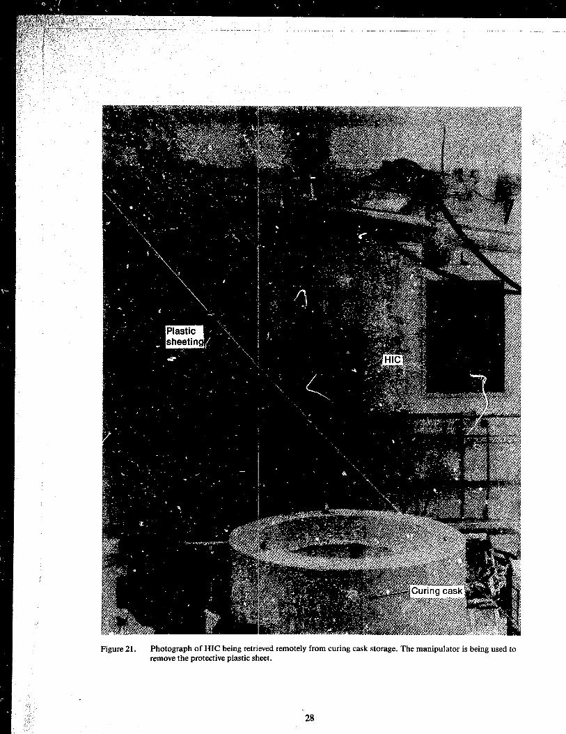
Figure 21. Photograph of HIe being retrieved remotely from curing cask storage. The manipulator is being used to remove the protective plastic sheet.
28

" . , - _" -I _ _ __ _
Figure 22. Photograph of HIe being lowered remotely into shipping cask.
29

Figure 23. Photograph of tractor, shipping cask, and trailer being moved outsicle the TAN hot shop.
Figure 24. Photograph of HIC being removed from the shipping cask at the u.s. ecology site.
30

. . . . l " •
• ~ I .... .. . '. - --- -
i Figure 25. Photograph of HIe being lowered into disposal trench at U.S. ecology site.
~ t l{
f t
I [ t t
I
~ f f
~ " J f • f. t ~ i
f r • ~" tc f r f ., • . '
~ [
t f'
~ Figure 26. Photograph of HIe being covered with soil using a clam-shell equipped crane.
r
1 31

6. CONCLUSIONS
A number of conclusions can be drawn from the results of this project:
• Disposal of the 4S EPICOR-II prefilters in HICs at a commercial low-level radioactive waste disposal site was a signi:icant accomplishment that required participation and cooperation of the DOE, NRC, the State of Washington, a private utility (GPU Nuclear), a government contractor (EG&G Idah,», and private industry (NuPac, US Ecology, and Chem Nuclear Systems).
• The participants, working together, solved a difficult waste disposal problem by applying available technologies in a new way.
• The commercial disposal of the 4S EPICOR premters using the newly developed HIC was aCCOiilp Iished in a safe, efficient, and expeditious manner, thus proving that the equip-
ment and procedures comprised a viable commercial grade system ready for use by the nuclear industry.
• The design ofthe HIC system offers assurance that a long-term, safe disposal means is available for disposal of high specific activity ion exchange material such as the EPICOR-II prefilters.
• A waste disposal scheme should be reviewed critically before and during implementation to identify places where simplification and improvement can be made. .
The equipment and procedural changes instituted by EG&G Idaho after disposing of the demonstration unit were significant in minimizing man-rem exposures per ALARA criteria, maximizing the safety on all handling tasks, and accelerating completion of the disposal program 3-l/2-months ahead of schedule.
7. REFERENCEsa
I. "Licensing Requirements for Land Disposal of Radioactive Waste," U.S. Nuclear Regulatory Comclission, 10 CFR 61.
2. R. C. Schmitt et aI., "High Integrity Containers: A Demonstration Disposal Alternative to Solidification of Radioactive Wastes," Waste Management 84, Volume 2, Low-Level Waste, Volume Reduction Methodologies alld Economics, 1iIcson, AZ, March 11-15, 1984, p. S37.
3. A. L. Ayers et al., Safety Assessment Document with Environmental Synopsis for Shipping HICs Loaded with EPICOR-/I Liners from INEL to Richland Disposal Facility, EGG-TMI-6414, September 1983.
4. Memorandum for the President of the United States from James B. Edwards, Secretary of Energy, "Resolution of Remaining Civilian Nuclear Program Policy and Budget Issues for FY 1982," 2 March 1981.a
S. Memorandum for the Secretary of Energy from the President of the United States, "Decisic,fls on Department of Energy Budget Appeal," 20 March 1981.
6. H. W. Reno, J. W. McConnell, Jr., R. C. Schmitt, EPICOR II Research and Disposition Program: FY-1983 Annual Report, EGG-2287, April 1984.
7. J. W. McConnell Jr., M. J. Tyacke, R. S. Schmitt, H. W. Reno, Disposal Demonstration of High Integrity Container (HIC) Containing an EPICOR-II Prefilter from Three Mile Island, GEND-04S, February 1985.
a. Copies of internal documents are available through the TMI-2 Technical Integration Office.
32

8. J. W. McConnell, Jr. and H. Spaletta, Metallurgical Examination of and Resin Transfer from Three Mile Island Prefilter Liners, GEND-036, August 1984.
9. J. D. Yesso, V, Pasupathi, L. Lowry, Characterization of EPTCOR-II Prefilter Liner i6, GEND-015, Battelle Memorial Institute Columbus Laboratories, August 1982.
10. Design Analysis Report for High Integrity Waste Disposal Container, Nuclear Packaging, Inc., 4 December 1981. a
II. Design Analysis Report for High Integrity Waste Disposal Container, Nuclear Packaging, Inc., Rev. 1. September 1982. a
12. R. L. Chapman and H. W. Reno, Design Analysis Report: High Integrity Container for Disposal of EPICOR-II Prefilter Liners, EGG-TMI-6304, June 1983.
13. R. C. Schmitt and H. W. Reno, "Experience in Development, Qualification, and Use of Concrete High-Integrity Containers in Commercial Disposal of Radioactive Wastes" Waste Management '85, Volume 2, Low-Level Waste, Waste Isolation in the U.S., Technical Programs and Public Participation, 1ltscon, AZ, March 24-28,1985, p 299-301.
'.
a. Copies I)f internal documents are available through the TMI-2 Technical Integration Office.
33