commands: show cable h to v · table 3: show cable image-upgrade version field descriptions field...
TRANSCRIPT
Commands: show cable h to v
• show cable heartbeat, page 3
• show cable image-upgrade bundle, page 5
• show cable image-upgrade status, page 7
• show cable image-upgrade version, page 8
• show cable licenses, page 10
• show cable linecard carrier-id-mapping, page 12
• show cable linecard coreinfo, page 18
• show cable linecard cpuload, page 20
• show cable linecard load-balancing-group, page 22
• show cable linecard logical-qamid-mapping, page 24
• show cable linecard logs, page 26
• show cable linecard process, page 29
• show cable linecard version, page 31
• show cable midplane ping statistics, page 33
• show cable qam-partition, page 35
• show cable qam-replication-group, page 43
• show cable rf-profile, page 45
• show cable service group, page 47
• show cable video gqi, page 50
• show cable video label, page 54
• show cable video multicast uplink, page 57
• show cable video packet, page 59
• show cable video route, page 61
• show cable video scrambler, page 63
Cisco RF Gateway 10 Command Reference 1

• show cable video server-group, page 73
• show cable video session, page 75
• show cable video statistics packet, page 85
• show controllers linecard, page 88
• show controllers qam, page 90
• show depi, page 92
• show depi session, page 94
• show depi tunnel, page 99
• show interfaces qam, page 102
• show redundancy, page 108
• show redundancy linecard, page 113
• show redundancy tcc, page 116
• show running-config interface qam, page 118
• ssm, page 120
• video route, page 123
Cisco RF Gateway 10 Command Reference2
Commands: show cable h to v
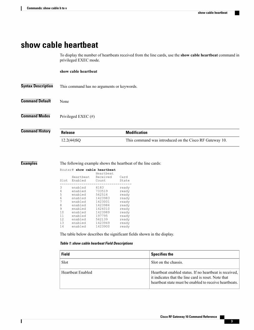
show cable heartbeatTo display the number of heartbeats received from the line cards, use the show cable heartbeat command inprivileged EXEC mode.
show cable heartbeat
Syntax Description This command has no arguments or keywords.
Command Default None
Command Modes Privileged EXEC (#)
Command History ModificationRelease
This command was introduced on the Cisco RF Gateway 10.12.2(44)SQ
Examples The following example shows the heartbeat of the line cards:Router# show cable heartbeat
HeartbeatHeartbeat Received Card
Slot Enabled Count State------------------------------------3 enabled 6183 ready4 enabled 733519 ready5 enabled 562516 ready6 enabled 1423983 ready7 enabled 1423001 ready8 enabled 1423984 ready9 enabled 1424010 ready10 enabled 1423989 ready11 enabled 197795 ready12 enabled 562139 ready13 enabled 1423949 ready14 enabled 1423900 ready
The table below describes the significant fields shown in the display.
Table 1: show cable hearbeat Field Descriptions
Specifies theField
Slot on the chassis.Slot
Heartbeat enabled status. If no heartbeat is received,it indicates that the line card is reset. Note thatheartbeat state must be enabled to receive heartbeats.
Heartbeat Enabled
Cisco RF Gateway 10 Command Reference 3
Commands: show cable h to vshow cable heartbeat
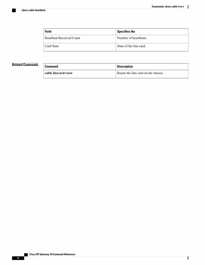
Specifies theField
Number of heartbeats.Heartbeat Received Count
State of the line card.Card State
Related Commands DescriptionCommand
Resets the line card on the chassis.cable linecard reset
Cisco RF Gateway 10 Command Reference4
Commands: show cable h to vshow cable heartbeat
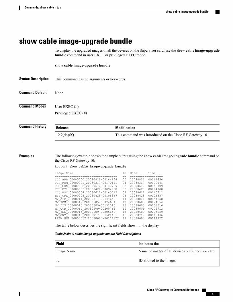
show cable image-upgrade bundleTo display the upgraded images of all the devices on the Supervisor card, use the show cable image-upgradebundle command in user EXEC or privileged EXEC mode.
show cable image-upgrade bundle
Syntax Description This command has no arguments or keywords.
Command Default None
Command Modes User EXEC (>)
Privileged EXEC (#)
Command History ModificationRelease
This command was introduced on the Cisco RF Gateway 10.12.2(44)SQ
Examples The following example shows the sample output using the show cable image-upgrade bundle command onthe Cisco RF Gateway 10:Router# show cable image-upgrade bundle
Image Name Id Date Time================================== == ==================TCC_APP_00000000_20080811-00144654 00 20080811 00144654TCC_ROM_00000001_20080317-00170141 01 20080317 00170141TCC_GEN_00000002_20080612-00140709 02 20080612 00140709TCC_DTI_00000003_20080428-00094708 03 20080428 00094708TCC_RST_00000004_20080612-00140712 04 20080612 00140712RFS_CPL_00000005_20080428-00105357 05 20080428 00105357MV_APP_00000011_20080811-00144650 11 20080811 00144650MV_ROM_00000012_20080605-00074654 12 20080605 00074654MV_DIS_00000013_20080603-00151016 13 20080603 00151016MV_COB_00000014_20080609-00205712 14 20080609 00205712MV_YEL_00000015_20080609-00205659 15 20080609 00205659MV_GWT_00000016_20080717-00162446 16 20080717 00162446RFGW_GUI_00000017_20080603-00114822 17 20080603 00114822
The table below describes the significant fields shown in the display.
Table 2: show cable image-upgrade bundle Field Descriptions
Indicates theField
Name of images of all devices on Supervisor card.Image Name
ID allotted to the image.Id
Cisco RF Gateway 10 Command Reference 5
Commands: show cable h to vshow cable image-upgrade bundle

Indicates theField
Date when the image was created.Date
Time when the image was created.Time
Related Commands DescriptionCommand
Upgrades the image on the specified line card.cable-image upgrade download
Displays the image upgraded status of the line card.show cable-image upgrade status
Displays all the upgraded image versions on the linecard.
show cable-image upgrade version
Cisco RF Gateway 10 Command Reference6
Commands: show cable h to vshow cable image-upgrade bundle

show cable image-upgrade statusTo display the upgrade status for a line card, use the show cable image-upgrade status command in userEXEC or privileged EXEC mode.
show cable image-upgrade status slot
Syntax Description Specifies the slot number of the line card. Validranges are from 3 to 12.
slot
Command Default None
Command Modes User EXEC (>)
Privileged EXEC (#)
Command History ModificationRelease
This command was introduced on the Cisco RF Gateway 10.12.2(44)SQ
Examples The following example displays the upgrade status for the line card:Router# show cable image-upgrade status 12No current image upgrade is occurring on slot 12
Related Commands DescriptionCommand
Upgrades the image on the specified line card.cable-image upgrade download
Displays the upgraded images of all the devices onthe Supervisor card.
show cable-image upgrade bundle
Displays all the upgraded image versions on the linecard.
show cable-image upgrade version
Cisco RF Gateway 10 Command Reference 7
Commands: show cable h to vshow cable image-upgrade status
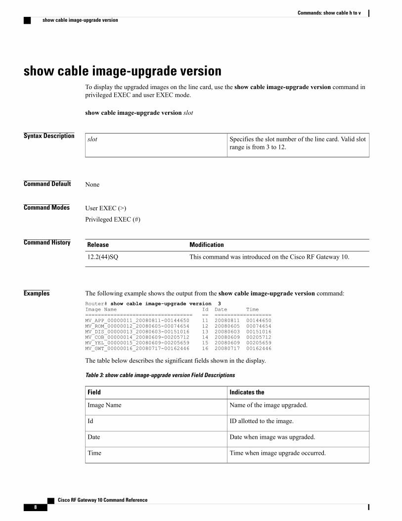
show cable image-upgrade versionTo display the upgraded images on the line card, use the show cable image-upgrade version command inprivileged EXEC and user EXEC mode.
show cable image-upgrade version slot
Syntax Description Specifies the slot number of the line card. Valid slotrange is from 3 to 12.
slot
Command Default None
Command Modes User EXEC (>)
Privileged EXEC (#)
Command History ModificationRelease
This command was introduced on the Cisco RF Gateway 10.12.2(44)SQ
Examples The following example shows the output from the show cable image-upgrade version command:Router# show cable image-upgrade version 3Image Name Id Date Time================================== == ==================MV_APP_00000011_20080811-00144650 11 20080811 00144650MV_ROM_00000012_20080605-00074654 12 20080605 00074654MV_DIS_00000013_20080603-00151016 13 20080603 00151016MV_COB_00000014_20080609-00205712 14 20080609 00205712MV_YEL_00000015_20080609-00205659 15 20080609 00205659MV_GWT_00000016_20080717-00162446 16 20080717 00162446
The table below describes the significant fields shown in the display.
Table 3: show cable image-upgrade version Field Descriptions
Indicates theField
Name of the image upgraded.Image Name
ID allotted to the image.Id
Date when image was upgraded.Date
Time when image upgrade occurred.Time
Cisco RF Gateway 10 Command Reference8
Commands: show cable h to vshow cable image-upgrade version
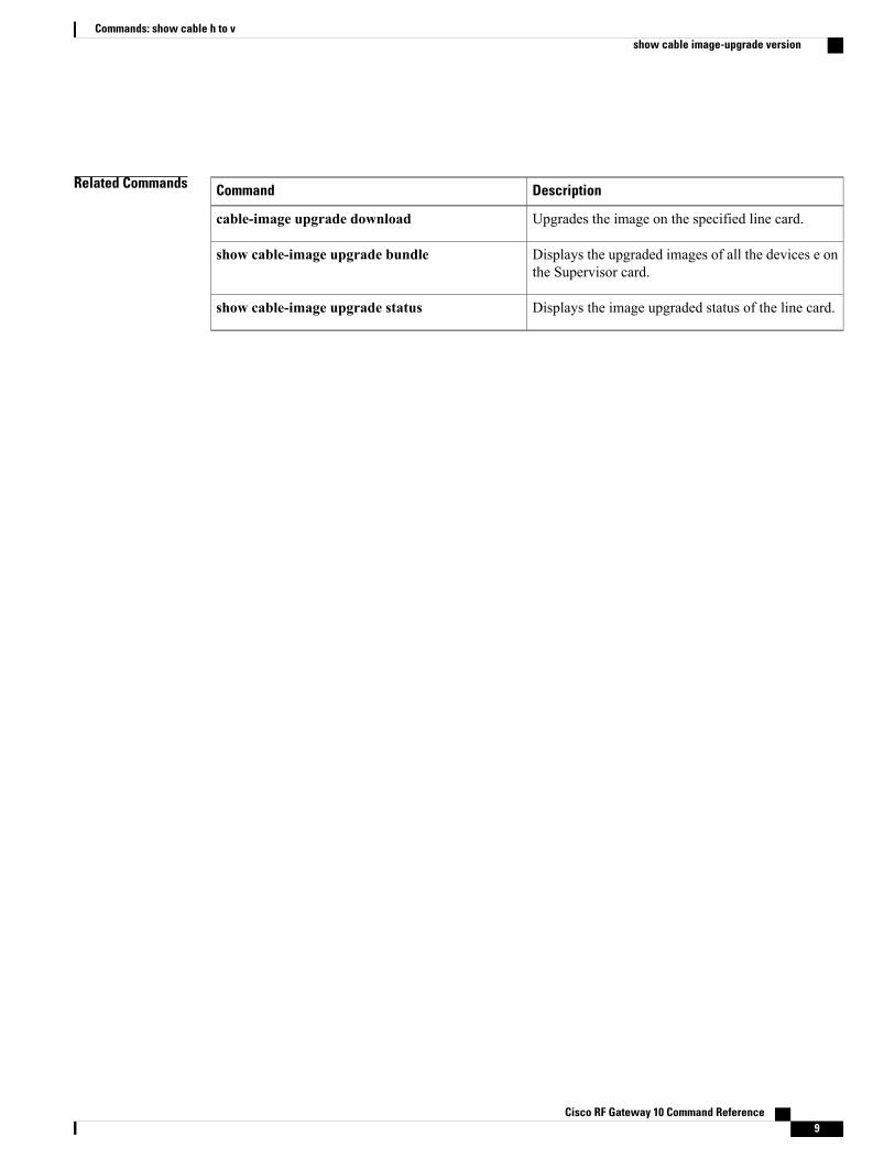
Related Commands DescriptionCommand
Upgrades the image on the specified line card.cable-image upgrade download
Displays the upgraded images of all the devices e onthe Supervisor card.
show cable-image upgrade bundle
Displays the image upgraded status of the line card.show cable-image upgrade status
Cisco RF Gateway 10 Command Reference 9
Commands: show cable h to vshow cable image-upgrade version
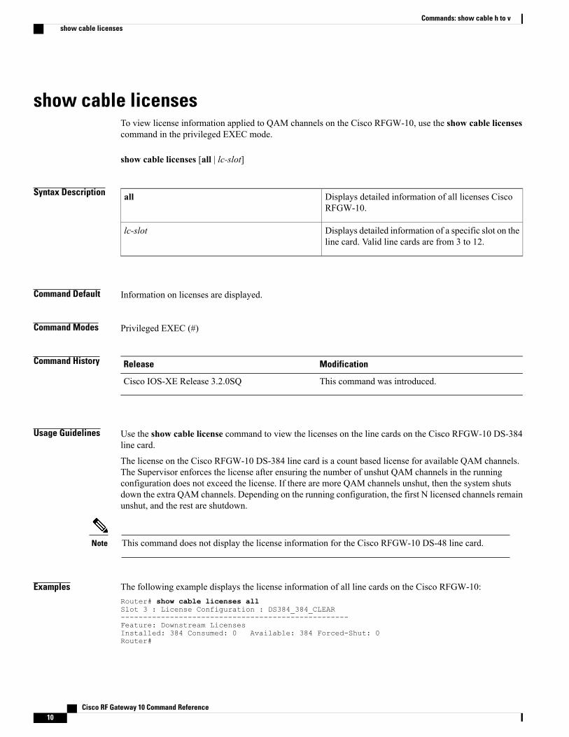
show cable licensesTo view license information applied to QAM channels on the Cisco RFGW-10, use the show cable licensescommand in the privileged EXEC mode.
show cable licenses [all | lc-slot]
Syntax Description Displays detailed information of all licenses CiscoRFGW-10.
all
Displays detailed information of a specific slot on theline card. Valid line cards are from 3 to 12.
lc-slot
Command Default Information on licenses are displayed.
Command Modes Privileged EXEC (#)
Command History ModificationRelease
This command was introduced.Cisco IOS-XE Release 3.2.0SQ
Usage Guidelines Use the show cable license command to view the licenses on the line cards on the Cisco RFGW-10 DS-384line card.
The license on the Cisco RFGW-10 DS-384 line card is a count based license for available QAM channels.The Supervisor enforces the license after ensuring the number of unshut QAM channels in the runningconfiguration does not exceed the license. If there are more QAM channels unshut, then the system shutsdown the extra QAM channels. Depending on the running configuration, the first N licensed channels remainunshut, and the rest are shutdown.
This command does not display the license information for the Cisco RFGW-10 DS-48 line card.Note
Examples The following example displays the license information of all line cards on the Cisco RFGW-10:Router# show cable licenses allSlot 3 : License Configuration : DS384_384_CLEAR---------------------------------------------------Feature: Downstream LicensesInstalled: 384 Consumed: 0 Available: 384 Forced-Shut: 0Router#
Cisco RF Gateway 10 Command Reference10
Commands: show cable h to vshow cable licenses
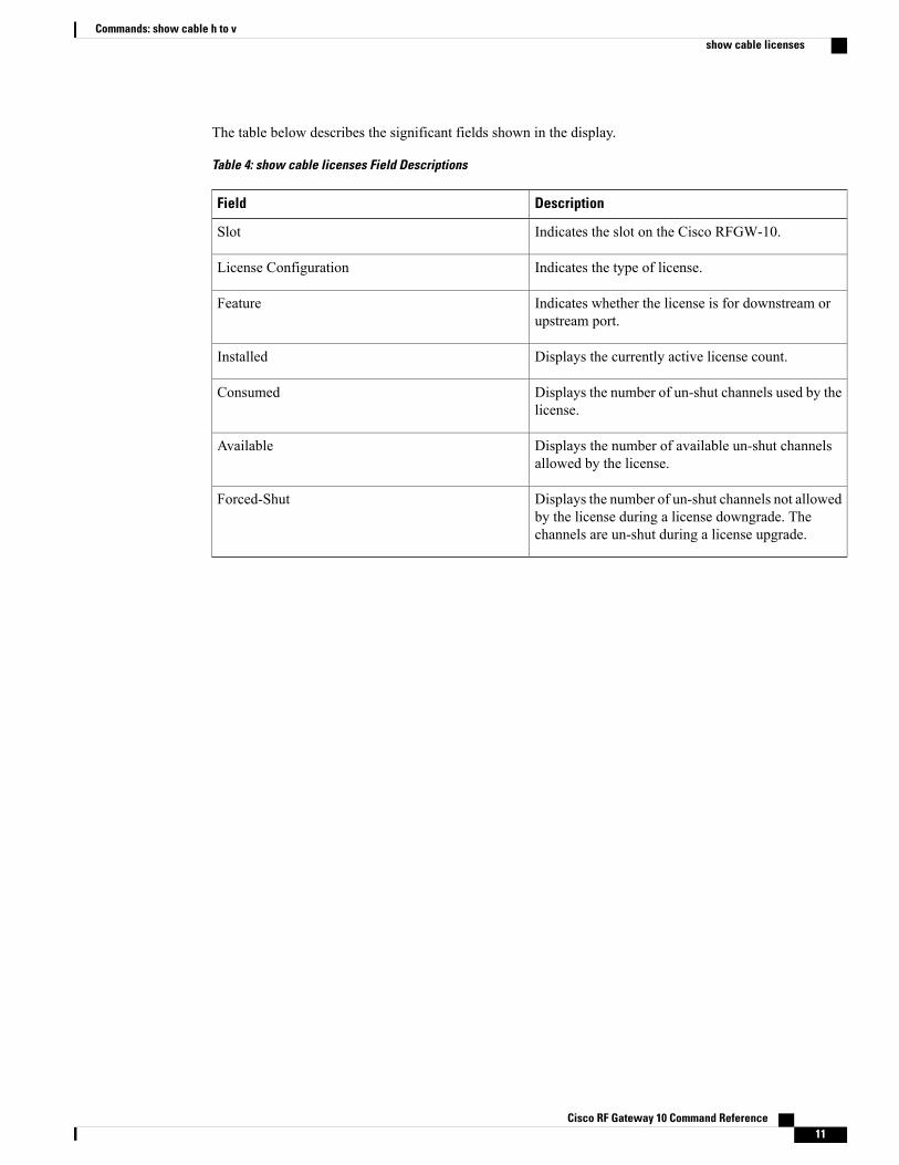
The table below describes the significant fields shown in the display.
Table 4: show cable licenses Field Descriptions
DescriptionField
Indicates the slot on the Cisco RFGW-10.Slot
Indicates the type of license.License Configuration
Indicates whether the license is for downstream orupstream port.
Feature
Displays the currently active license count.Installed
Displays the number of un-shut channels used by thelicense.
Consumed
Displays the number of available un-shut channelsallowed by the license.
Available
Displays the number of un-shut channels not allowedby the license during a license downgrade. Thechannels are un-shut during a license upgrade.
Forced-Shut
Cisco RF Gateway 10 Command Reference 11
Commands: show cable h to vshow cable licenses
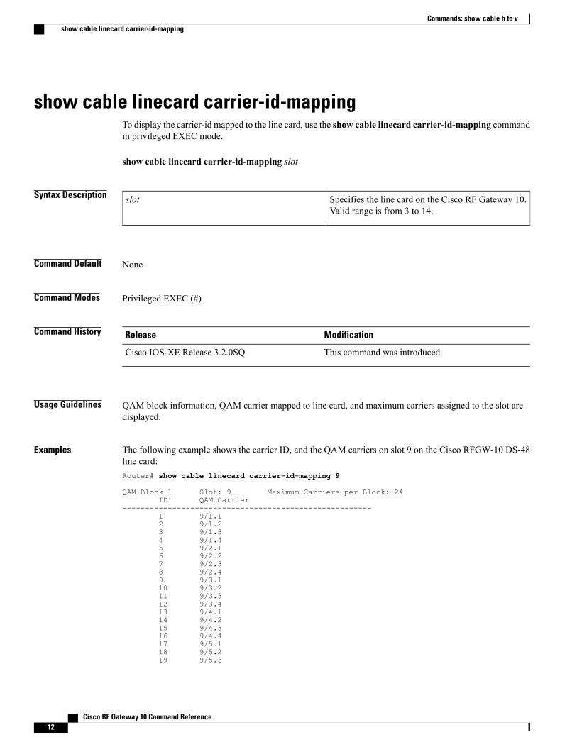
show cable linecard carrier-id-mappingTo display the carrier-id mapped to the line card, use the show cable linecard carrier-id-mapping commandin privileged EXEC mode.
show cable linecard carrier-id-mapping slot
Syntax Description Specifies the line card on the Cisco RF Gateway 10.Valid range is from 3 to 14.
slot
Command Default None
Command Modes Privileged EXEC (#)
Command History ModificationRelease
This command was introduced.Cisco IOS-XE Release 3.2.0SQ
Usage Guidelines QAM block information, QAM carrier mapped to line card, and maximum carriers assigned to the slot aredisplayed.
Examples The following example shows the carrier ID, and the QAM carriers on slot 9 on the Cisco RFGW-10 DS-48line card:Router# show cable linecard carrier-id-mapping 9
QAM Block 1 Slot: 9 Maximum Carriers per Block: 24ID QAM Carrier
-------------------------------------------------------1 9/1.12 9/1.23 9/1.34 9/1.45 9/2.16 9/2.27 9/2.38 9/2.49 9/3.110 9/3.211 9/3.312 9/3.413 9/4.114 9/4.215 9/4.316 9/4.417 9/5.118 9/5.219 9/5.3
Cisco RF Gateway 10 Command Reference12
Commands: show cable h to vshow cable linecard carrier-id-mapping
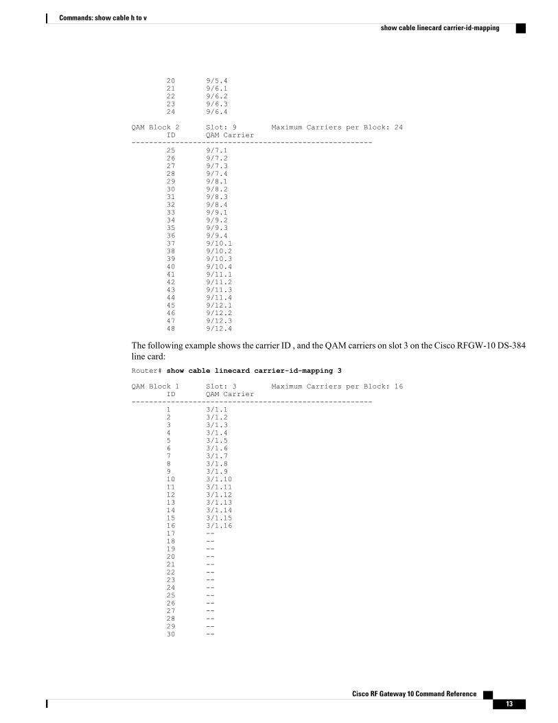
20 9/5.421 9/6.122 9/6.223 9/6.324 9/6.4
QAM Block 2 Slot: 9 Maximum Carriers per Block: 24ID QAM Carrier
-------------------------------------------------------25 9/7.126 9/7.227 9/7.328 9/7.429 9/8.130 9/8.231 9/8.332 9/8.433 9/9.134 9/9.235 9/9.336 9/9.437 9/10.138 9/10.239 9/10.340 9/10.441 9/11.142 9/11.243 9/11.344 9/11.445 9/12.146 9/12.247 9/12.348 9/12.4
The following example shows the carrier ID , and the QAM carriers on slot 3 on the Cisco RFGW-10 DS-384line card:Router# show cable linecard carrier-id-mapping 3
QAM Block 1 Slot: 3 Maximum Carriers per Block: 16ID QAM Carrier
-------------------------------------------------------1 3/1.12 3/1.23 3/1.34 3/1.45 3/1.56 3/1.67 3/1.78 3/1.89 3/1.910 3/1.1011 3/1.1112 3/1.1213 3/1.1314 3/1.1415 3/1.1516 3/1.1617 --18 --19 --20 --21 --22 --23 --24 --25 --26 --27 --28 --29 --30 --
Cisco RF Gateway 10 Command Reference 13
Commands: show cable h to vshow cable linecard carrier-id-mapping

31 --32 --33 --34 --35 --36 --37 --38 --39 --40 --41 --42 --43 --44 --45 --46 --47 --48 --49 --50 --51 --52 --53 --54 --55 --56 --57 --58 --59 --60 --61 --62 --63 --64 --65 --66 --67 --68 --69 --70 --71 --72 --73 --74 --75 --76 --77 --78 --79 --80 --81 --82 --83 --84 --85 --86 --87 --88 --89 --90 --91 --92 --93 --94 --95 --96 --97 --98 --99 --100 --101 --102 --103 --
Cisco RF Gateway 10 Command Reference14
Commands: show cable h to vshow cable linecard carrier-id-mapping
104 --105 --106 --107 --108 --109 --110 --111 --112 --113 --114 --115 --116 --117 --118 --119 --120 --121 --122 --123 --124 --125 --126 --127 --128 --129 --130 --131 --132 --133 --134 --135 --136 --137 --138 --139 --140 --141 --142 --143 --144 --145 --146 --147 --148 --149 --150 --151 --152 --153 --154 --155 --156 --157 --158 --159 --160 --161 --162 --163 --164 --165 --166 --167 --168 --169 --170 --171 --172 --173 --174 --175 --176 --
Cisco RF Gateway 10 Command Reference 15
Commands: show cable h to vshow cable linecard carrier-id-mapping
177 --178 --179 --180 --181 --182 --183 --184 --185 --186 --187 --188 --189 --190 --191 --192 --
QAM Block 2 Slot: 3 Maximum Carriers per Block: 0ID QAM Carrier
-------------------------------------------------------193 --194 --195 --196 --197 --198 --199 --200 --201 --202 --203 --204 --205 --206 --207 --208 --209 --210 --211 --212 --213 --214 --215 --216 --217 --218 --219 --220 --221 --222 --223 --224 --225 --226 --227 --228 --229 --230 --231 --232 --233 --234 --235 --236 --237 --238 --239 --240 --241 --242 --243 --244 --245 --
Cisco RF Gateway 10 Command Reference16
Commands: show cable h to vshow cable linecard carrier-id-mapping
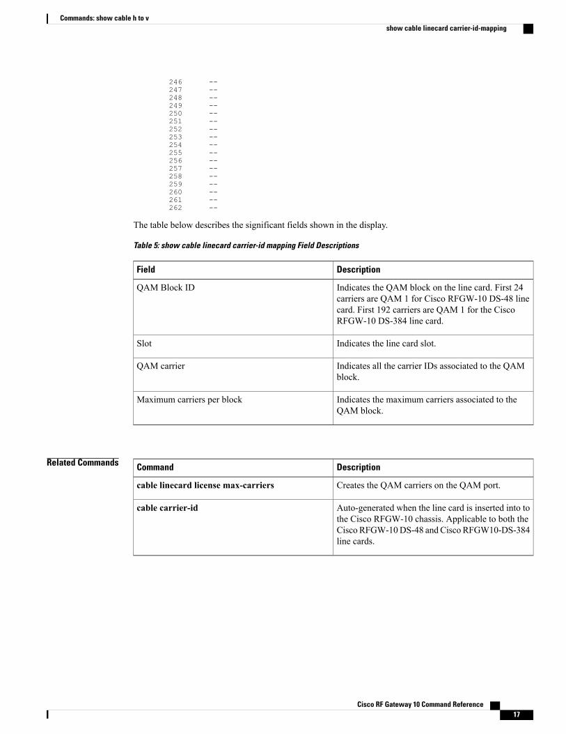
246 --247 --248 --249 --250 --251 --252 --253 --254 --255 --256 --257 --258 --259 --260 --261 --262 --
The table below describes the significant fields shown in the display.
Table 5: show cable linecard carrier-id mapping Field Descriptions
DescriptionField
Indicates the QAM block on the line card. First 24carriers are QAM 1 for Cisco RFGW-10 DS-48 linecard. First 192 carriers are QAM 1 for the CiscoRFGW-10 DS-384 line card.
QAM Block ID
Indicates the line card slot.Slot
Indicates all the carrier IDs associated to the QAMblock.
QAM carrier
Indicates the maximum carriers associated to theQAM block.
Maximum carriers per block
Related Commands DescriptionCommand
Creates the QAM carriers on the QAM port.cable linecard license max-carriers
Auto-generated when the line card is inserted into tothe Cisco RFGW-10 chassis. Applicable to both theCisco RFGW-10DS-48 and Cisco RFGW10-DS-384line cards.
cable carrier-id
Cisco RF Gateway 10 Command Reference 17
Commands: show cable h to vshow cable linecard carrier-id-mapping
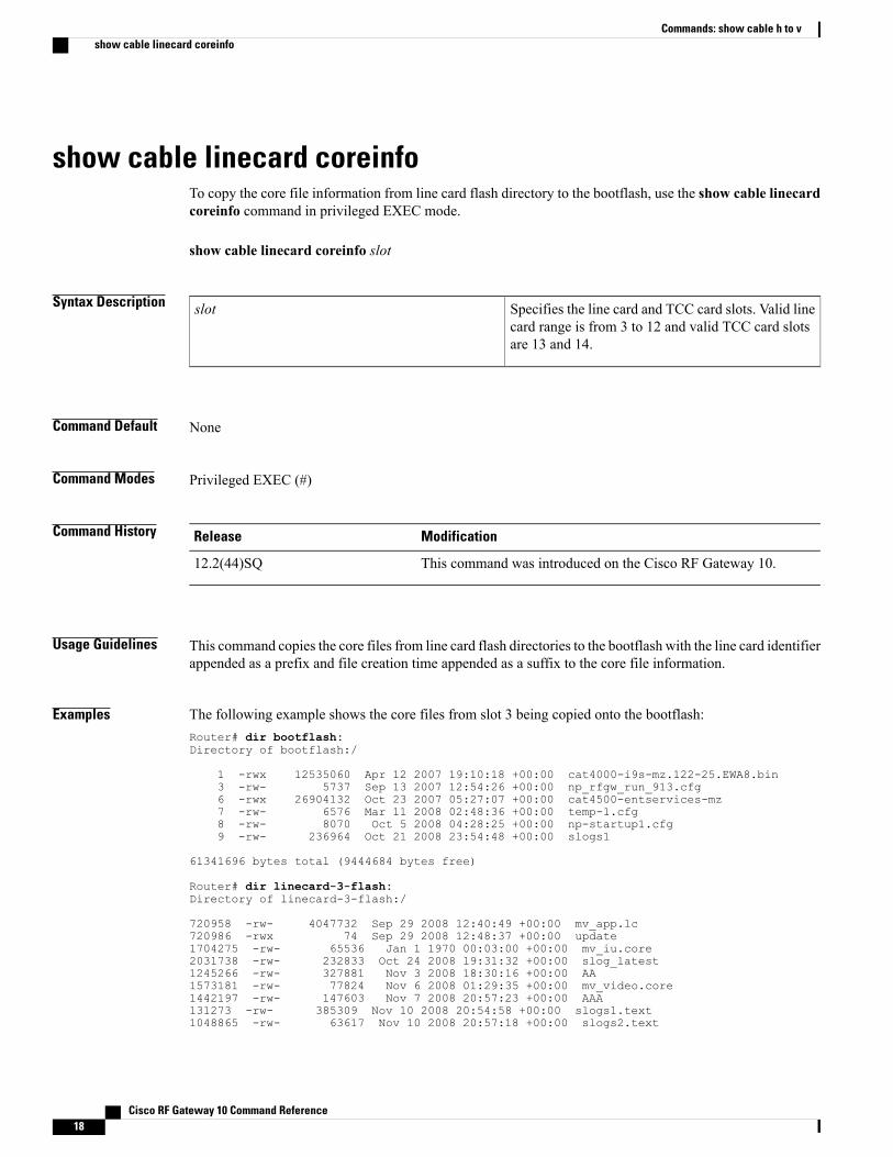
show cable linecard coreinfoTo copy the core file information from line card flash directory to the bootflash, use the show cable linecardcoreinfo command in privileged EXEC mode.
show cable linecard coreinfo slot
Syntax Description Specifies the line card and TCC card slots. Valid linecard range is from 3 to 12 and valid TCC card slotsare 13 and 14.
slot
Command Default None
Command Modes Privileged EXEC (#)
Command History ModificationRelease
This command was introduced on the Cisco RF Gateway 10.12.2(44)SQ
Usage Guidelines This command copies the core files from line card flash directories to the bootflash with the line card identifierappended as a prefix and file creation time appended as a suffix to the core file information.
Examples The following example shows the core files from slot 3 being copied onto the bootflash:Router# dir bootflash:Directory of bootflash:/
1 -rwx 12535060 Apr 12 2007 19:10:18 +00:00 cat4000-i9s-mz.122-25.EWA8.bin3 -rw- 5737 Sep 13 2007 12:54:26 +00:00 np_rfgw_run_913.cfg6 -rwx 26904132 Oct 23 2007 05:27:07 +00:00 cat4500-entservices-mz7 -rw- 6576 Mar 11 2008 02:48:36 +00:00 temp-1.cfg8 -rw- 8070 Oct 5 2008 04:28:25 +00:00 np-startup1.cfg9 -rw- 236964 Oct 21 2008 23:54:48 +00:00 slogs1
61341696 bytes total (9444684 bytes free)
Router# dir linecard-3-flash:Directory of linecard-3-flash:/
720958 -rw- 4047732 Sep 29 2008 12:40:49 +00:00 mv_app.lc720986 -rwx 74 Sep 29 2008 12:48:37 +00:00 update1704275 -rw- 65536 Jan 1 1970 00:03:00 +00:00 mv_iu.core2031738 -rw- 232833 Oct 24 2008 19:31:32 +00:00 slog_latest1245266 -rw- 327881 Nov 3 2008 18:30:16 +00:00 AA1573181 -rw- 77824 Nov 6 2008 01:29:35 +00:00 mv_video.core1442197 -rw- 147603 Nov 7 2008 20:57:23 +00:00 AAA131273 -rw- 385309 Nov 10 2008 20:54:58 +00:00 slogs1.text1048865 -rw- 63617 Nov 10 2008 20:57:18 +00:00 slogs2.text
Cisco RF Gateway 10 Command Reference18
Commands: show cable h to vshow cable linecard coreinfo

327848 -rw- 385309 Nov 10 2008 20:54:58 +00:00 slogs1_boot.text458769 -rw- 63617 Nov 10 2008 20:57:18 +00:00 slogs2_boot.text196793 -rw- 20036 Jan 1 1970 00:00:14 +00:00 slogs1_boot.txt524465 -rw- 114208 Dec 9 2008 20:33:25 +00:00 slogs1
8126464 bytes total (1719532 bytes free)
Router# show cable linecard coreinfo 3Copying core file linecard-3-flash:mv_video.core tobootflash:LC_3_mv_video.core_012935_6_Nov_2008
Copying core file linecard-3-flash:mv_iu.core to bootflash:LC_3_mv_iu.core_000300_1_Jan_1970Router#dir bootflash:Directory of bootflash:/
1 -rwx 12535060 Apr 12 2007 19:10:18 +00:00 cat4000-i9s-mz.122-25.EWA8.bin3 -rw- 5737 Sep 13 2007 12:54:26 +00:00 np_rfgw_run_913.cfg6 -rwx 26904132 Oct 23 2007 05:27:07 +00:00 cat4500-entservices-mz7 -rw- 6576 Mar 11 2008 02:48:36 +00:00 temp-1.cfg8 -rw- 8070 Oct 5 2008 04:28:25 +00:00 np-startup1.cfg9 -rw- 236964 Oct 21 2008 23:54:48 +00:00 slogs121 -rw- 77824 Dec 9 2008 20:33:51 +00:00 LC_3_mv_video.core_012935_6_Nov_200822 -rw- 65536 Dec 9 2008 20:33:51 +00:00 LC_3_mv_iu.core_000300_1_Jan_1970
61341696 bytes total (9301068 bytes free)
The table below describes the significant fields shown in the display.
Table 6: show cable linecard coreinfo Field Descriptions
DescriptionField
Shows the copying of the files to the bootflashdirectory.
Copying core file line card
Related Commands DescriptionCommand
Displays the version information for a line card.show cable linecard version
Cisco RF Gateway 10 Command Reference 19
Commands: show cable h to vshow cable linecard coreinfo
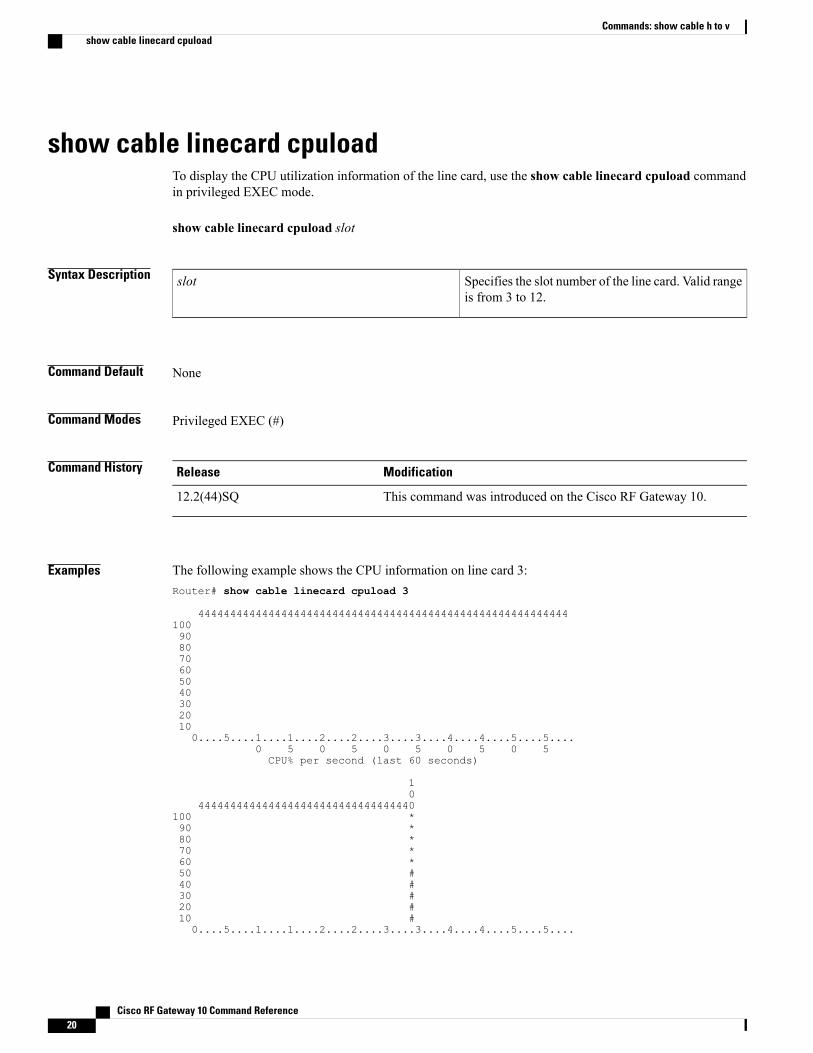
show cable linecard cpuloadTo display the CPU utilization information of the line card, use the show cable linecard cpuload commandin privileged EXEC mode.
show cable linecard cpuload slot
Syntax Description Specifies the slot number of the line card. Valid rangeis from 3 to 12.
slot
Command Default None
Command Modes Privileged EXEC (#)
Command History ModificationRelease
This command was introduced on the Cisco RF Gateway 10.12.2(44)SQ
Examples The following example shows the CPU information on line card 3:Router# show cable linecard cpuload 3
44444444444444444444444444444444444444444444444444444444441009080706050403020100....5....1....1....2....2....3....3....4....4....5....5....
0 5 0 5 0 5 0 5 0 5CPU% per second (last 60 seconds)
10
4444444444444444444444444444444440100 *90 *80 *70 *60 *50 #40 #30 #20 #10 #0....5....1....1....2....2....3....3....4....4....5....5....
Cisco RF Gateway 10 Command Reference20
Commands: show cable h to vshow cable linecard cpuload
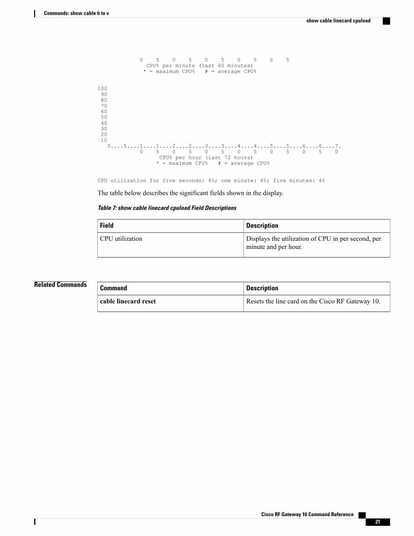
0 5 0 5 0 5 0 5 0 5CPU% per minute (last 60 minutes)* = maximum CPU% # = average CPU%
1009080706050403020100....5....1....1....2....2....3....3....4....4....5....5....6....6....7.
0 5 0 5 0 5 0 5 0 5 0 5 0CPU% per hour (last 72 hours)* = maximum CPU% # = average CPU%
CPU utilization for five seconds: 4%; one minute: 4%; five minutes: 4%
The table below describes the significant fields shown in the display.
Table 7: show cable linecard cpuload Field Descriptions
DescriptionField
Displays the utilization of CPU in per second, perminute and per hour.
CPU utilization
Related Commands DescriptionCommand
Resets the line card on the Cisco RF Gateway 10.cable linecard reset
Cisco RF Gateway 10 Command Reference 21
Commands: show cable h to vshow cable linecard cpuload

show cable linecard load-balancing-groupTo display the load balancing groups created on the Cisco RFGW-10, use the show cable line cardload-balancing-group command in privileged EXEC mode.
show cable linecard slot load-balancing-group
Syntax Description Line card slot on the Cisco RFGW-10. Valid rangeis from 3 to14.
slot
Command Default This command is disabled by default.
Command Modes Privileged EXEC (#)
Command History ModificationRelease
This command was introduced.Cisco IOS-XE Release 3.2.0SQ
Usage Guidelines Use the show cable linecard load-balancing-group command to view the load balanced groups on the CiscoRFGW-10.
Examples The following example displays the load balancing groups on line card slot 3 on the Cisco RFGW-10:Router# show cable linecard 3 load-balancing-group all
Slot : 3 Load-balancing Group : 1Total Bandwidth : 10000000 KBpsAvailable Bandwidth : 10000000 KBpsReserved Bandwidth for QAM Based Sessions : 0 KBpsReserved Bandwidth for IP Based Sessions : 0 KBpsSlot : 3 Load-balancing Group : 2Total Bandwidth : 10000000 KBpsAvailable Bandwidth : 10000000 KBpsReserved Bandwidth for QAM Based Sessions : 0 KBpsReserved Bandwidth for IP Based Sessions : 0 KBps
The table below describes the significant fields shown in the display.
Table 8: show cable linecard load-balancing-group Field Descriptions
DescriptionField
Indicates the line card slot.Slot
Cisco RF Gateway 10 Command Reference22
Commands: show cable h to vshow cable linecard load-balancing-group
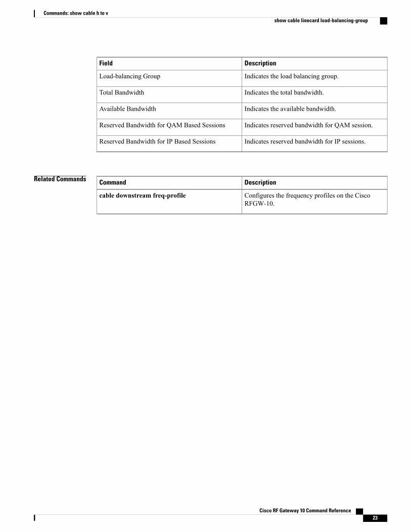
DescriptionField
Indicates the load balancing group.Load-balancing Group
Indicates the total bandwidth.Total Bandwidth
Indicates the available bandwidth.Available Bandwidth
Indicates reserved bandwidth for QAM session.Reserved Bandwidth for QAM Based Sessions
Indicates reserved bandwidth for IP sessions.Reserved Bandwidth for IP Based Sessions
Related Commands DescriptionCommand
Configures the frequency profiles on the CiscoRFGW-10.
cable downstream freq-profile
Cisco RF Gateway 10 Command Reference 23
Commands: show cable h to vshow cable linecard load-balancing-group
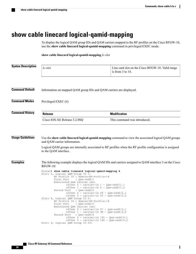
show cable linecard logical-qamid-mappingTo display the logical QAM group IDs and QAM carriers mapped to the RF profiles on the Cisco RFGW-10,use the show cable linecard logical-qamid-mapping command in privileged EXEC mode.
show cable linecard logical-qamid-mapping lc-slot
Syntax Description Line card slot on the Cisco RFGW-10. Valid rangeis from 3 to 14.
lc-slot
Command Default Information on mapped QAM group IDs and QAM carriers are displayed.
Command Modes Privileged EXEC (#)
Command History ModificationRelease
This command was introduced.Cisco IOS-XE Release 3.2.0SQ
Usage Guidelines Use the show cable linecard logical-qamid-mapping command to view the associated logical QAM groupsand QAM carrier information.
Logical QAM groups are internally associated to RF profiles when the RF profile configuration is assignedto the QAM interface.
Examples The following example displays the logical QAM IDs and carriers assigned to QAM interface 3 on the CiscoRFGW-10:Router# show cable linecard logical-qamid-mapping 4Slot: 4, Logical QAM Group ID 1:
RF Profile ID : Remote-RF-Profile-14First Port : Qam-red4/1Associated Qam Carrier ids:
offset 0 - carrier-id 1 - Qam-red4/1.1offset 1 - carrier-id 2 - Qam-red4/1.2
Second Port : Qam-red4/2offset 4 - carrier-id 49 - Qam-red4/2.1offset 5 - carrier-id 50 - Qam-red4/2.2
Slot: 4, Logical QAM Group ID 2:RF Profile ID : Remote-RF-Profile-14First Port : Qam-red4/3Associated Qam Carrier ids:
offset 0 - carrier-id 97 - Qam-red4/3.1offset 1 - carrier-id 98 - Qam-red4/3.2
Second Port : Qam-red4/4offset 4 - carrier-id 145 - Qam-red4/4.1offset 5 - carrier-id 146 - Qam-red4/4.2
Slot: 4, Logical QAM Group ID 33:
Cisco RF Gateway 10 Command Reference24
Commands: show cable h to vshow cable linecard logical-qamid-mapping
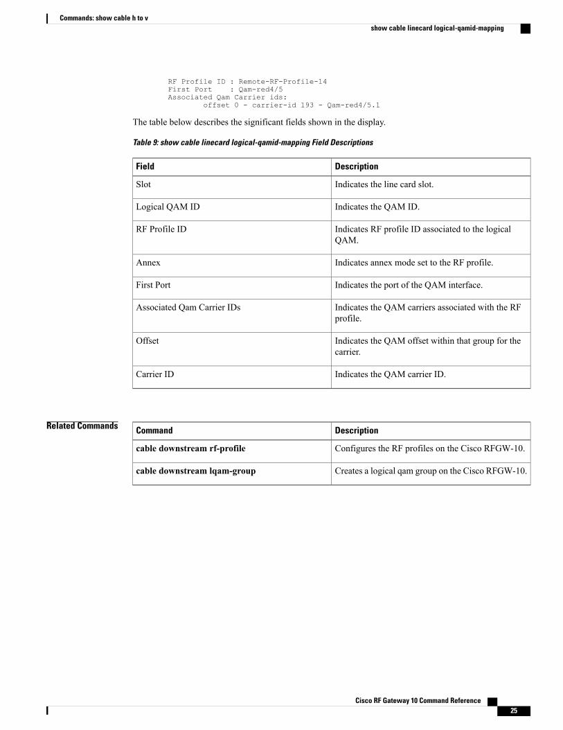
RF Profile ID : Remote-RF-Profile-14First Port : Qam-red4/5Associated Qam Carrier ids:
offset 0 - carrier-id 193 - Qam-red4/5.1
The table below describes the significant fields shown in the display.
Table 9: show cable linecard logical-qamid-mapping Field Descriptions
DescriptionField
Indicates the line card slot.Slot
Indicates the QAM ID.Logical QAM ID
Indicates RF profile ID associated to the logicalQAM.
RF Profile ID
Indicates annex mode set to the RF profile.Annex
Indicates the port of the QAM interface.First Port
Indicates the QAM carriers associated with the RFprofile.
Associated Qam Carrier IDs
Indicates the QAM offset within that group for thecarrier.
Offset
Indicates the QAM carrier ID.Carrier ID
Related Commands DescriptionCommand
Configures the RF profiles on the Cisco RFGW-10.cable downstream rf-profile
Creates a logical qam group on the Cisco RFGW-10.cable downstream lqam-group
Cisco RF Gateway 10 Command Reference 25
Commands: show cable h to vshow cable linecard logical-qamid-mapping
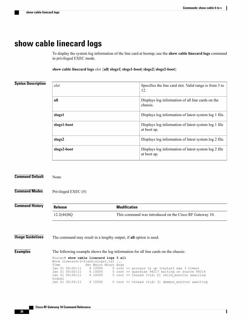
show cable linecard logsTo display the system log information of the line card at bootup, use the show cable linecard logs commandin privileged EXEC mode.
show cable linecard logs slot {all| slogs1| slogs1-boot| slogs2| slogs2-boot}
Syntax Description Specifies the line card slot. Valid range is from 3 to12.
slot
Displays log information of all line cards on thechassis.
all
Displays log information of latest system log 1 file.slogs1
Displays log information of latest system log 1 fileat boot up.
slogs1-boot
Displays log information of latest system log 2 file.slogs2
Displays log information of latest system log 2 fileat boot up.
slogs2-boot
Command Default None
Command Modes Privileged EXEC (#)
Command History ModificationRelease
This command was introduced on the Cisco RF Gateway 10.12.2(44)SQ
Usage Guidelines The command may result in a lengthy output, if all option is used.
Examples The following example shows the log information for all line cards on the chassis:Router# show cable linecard logs 3 allMore linecard-3-flash:slogs1.txt ...Time Sev Major Minor ArgsJan 01 00:00:11 6 10000 0 root >> process is up (restart max 3 times)Jan 01 00:00:11 6 10000 0 root >> guardian 94217 waiting on source 94216Jan 01 00:00:11 6 10000 0 root >> thread [tid: 2] child_monitor awaitingsignalJan 01 00:00:11 6 10000 0 root >> thread [tid: 3] daemon_monitor awaiting
Cisco RF Gateway 10 Command Reference26
Commands: show cable h to vshow cable linecard logs
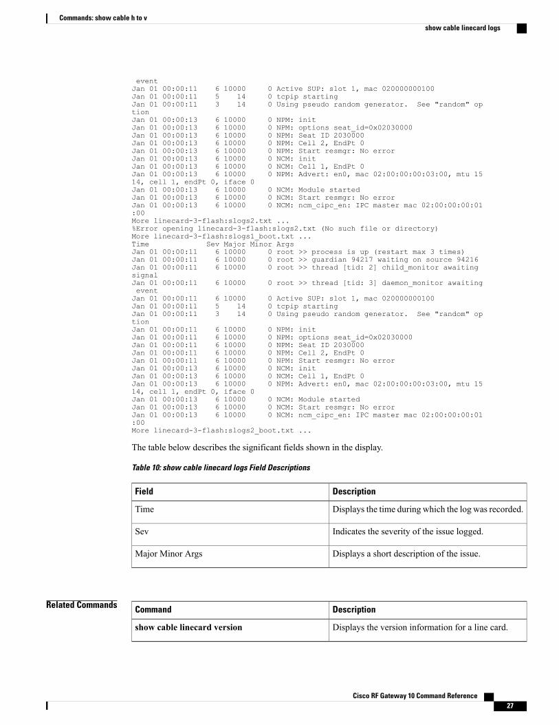
eventJan 01 00:00:11 6 10000 0 Active SUP: slot 1, mac 020000000100Jan 01 00:00:11 5 14 0 tcpip startingJan 01 00:00:11 3 14 0 Using pseudo random generator. See "random" optionJan 01 00:00:13 6 10000 0 NPM: initJan 01 00:00:13 6 10000 0 NPM: options seat_id=0x02030000Jan 01 00:00:13 6 10000 0 NPM: Seat ID 2030000Jan 01 00:00:13 6 10000 0 NPM: Cell 2, EndPt 0Jan 01 00:00:13 6 10000 0 NPM: Start resmgr: No errorJan 01 00:00:13 6 10000 0 NCM: initJan 01 00:00:13 6 10000 0 NCM: Cell 1, EndPt 0Jan 01 00:00:13 6 10000 0 NPM: Advert: en0, mac 02:00:00:00:03:00, mtu 1514, cell 1, endPt 0, iface 0Jan 01 00:00:13 6 10000 0 NCM: Module startedJan 01 00:00:13 6 10000 0 NCM: Start resmgr: No errorJan 01 00:00:13 6 10000 0 NCM: ncm_cipc_en: IPC master mac 02:00:00:00:01:00More linecard-3-flash:slogs2.txt ...%Error opening linecard-3-flash:slogs2.txt (No such file or directory)More linecard-3-flash:slogs1_boot.txt ...Time Sev Major Minor ArgsJan 01 00:00:11 6 10000 0 root >> process is up (restart max 3 times)Jan 01 00:00:11 6 10000 0 root >> guardian 94217 waiting on source 94216Jan 01 00:00:11 6 10000 0 root >> thread [tid: 2] child_monitor awaitingsignalJan 01 00:00:11 6 10000 0 root >> thread [tid: 3] daemon_monitor awaitingeventJan 01 00:00:11 6 10000 0 Active SUP: slot 1, mac 020000000100Jan 01 00:00:11 5 14 0 tcpip startingJan 01 00:00:11 3 14 0 Using pseudo random generator. See "random" optionJan 01 00:00:11 6 10000 0 NPM: initJan 01 00:00:11 6 10000 0 NPM: options seat_id=0x02030000Jan 01 00:00:11 6 10000 0 NPM: Seat ID 2030000Jan 01 00:00:11 6 10000 0 NPM: Cell 2, EndPt 0Jan 01 00:00:11 6 10000 0 NPM: Start resmgr: No errorJan 01 00:00:13 6 10000 0 NCM: initJan 01 00:00:13 6 10000 0 NCM: Cell 1, EndPt 0Jan 01 00:00:13 6 10000 0 NPM: Advert: en0, mac 02:00:00:00:03:00, mtu 1514, cell 1, endPt 0, iface 0Jan 01 00:00:13 6 10000 0 NCM: Module startedJan 01 00:00:13 6 10000 0 NCM: Start resmgr: No errorJan 01 00:00:13 6 10000 0 NCM: ncm_cipc_en: IPC master mac 02:00:00:00:01:00More linecard-3-flash:slogs2_boot.txt ...
The table below describes the significant fields shown in the display.
Table 10: show cable linecard logs Field Descriptions
DescriptionField
Displays the time during which the log was recorded.Time
Indicates the severity of the issue logged.Sev
Displays a short description of the issue.Major Minor Args
Related Commands DescriptionCommand
Displays the version information for a line card.show cable linecard version
Cisco RF Gateway 10 Command Reference 27
Commands: show cable h to vshow cable linecard logs

Cisco RF Gateway 10 Command Reference28
Commands: show cable h to vshow cable linecard logs
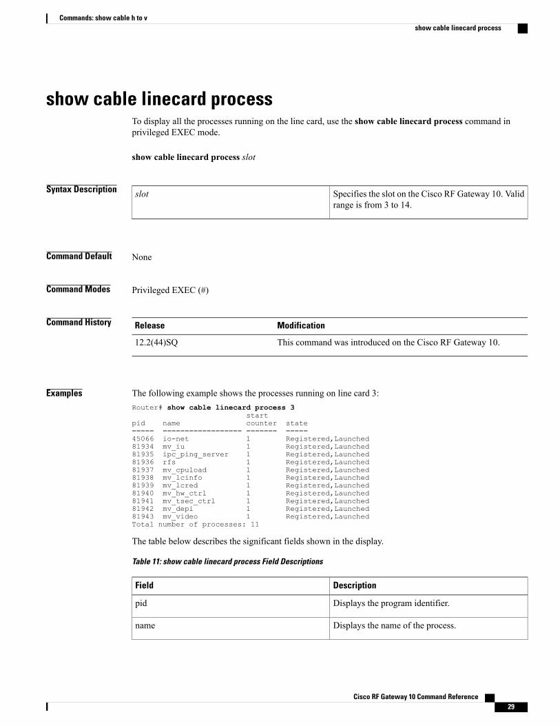
show cable linecard processTo display all the processes running on the line card, use the show cable linecard process command inprivileged EXEC mode.
show cable linecard process slot
Syntax Description Specifies the slot on the Cisco RF Gateway 10. Validrange is from 3 to 14.
slot
Command Default None
Command Modes Privileged EXEC (#)
Command History ModificationRelease
This command was introduced on the Cisco RF Gateway 10.12.2(44)SQ
Examples The following example shows the processes running on line card 3:Router# show cable linecard process 3
startpid name counter state===== ================== ======= =====45066 io-net 1 Registered,Launched81934 mv_iu 1 Registered,Launched81935 ipc_ping_server 1 Registered,Launched81936 rfs 1 Registered,Launched81937 mv_cpuload 1 Registered,Launched81938 mv_lcinfo 1 Registered,Launched81939 mv_lcred 1 Registered,Launched81940 mv_hw_ctrl 1 Registered,Launched81941 mv_tsec_ctrl 1 Registered,Launched81942 mv_depi 1 Registered,Launched81943 mv_video 1 Registered,LaunchedTotal number of processes: 11
The table below describes the significant fields shown in the display.
Table 11: show cable linecard process Field Descriptions
DescriptionField
Displays the program identifier.pid
Displays the name of the process.name
Cisco RF Gateway 10 Command Reference 29
Commands: show cable h to vshow cable linecard process
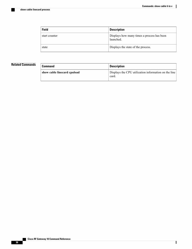
DescriptionField
Displays how many times a process has beenlaunched.
start counter
Displays the state of the process.state
Related Commands DescriptionCommand
Displays the CPU utilization information on the linecard.
show cable linecard cpuload
Cisco RF Gateway 10 Command Reference30
Commands: show cable h to vshow cable linecard process
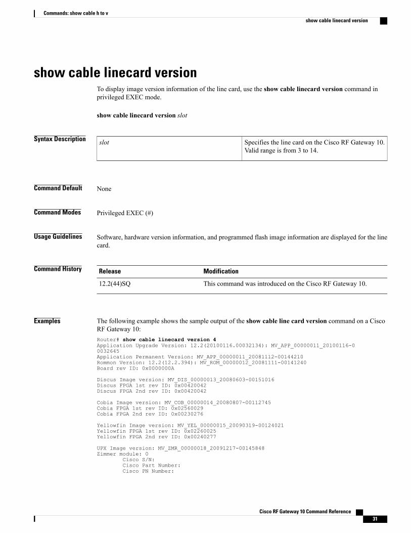
show cable linecard versionTo display image version information of the line card, use the show cable linecard version command inprivileged EXEC mode.
show cable linecard version slot
Syntax Description Specifies the line card on the Cisco RF Gateway 10.Valid range is from 3 to 14.
slot
Command Default None
Command Modes Privileged EXEC (#)
Usage Guidelines Software, hardware version information, and programmed flash image information are displayed for the linecard.
Command History ModificationRelease
This command was introduced on the Cisco RF Gateway 10.12.2(44)SQ
Examples The following example shows the sample output of the show cable line card version command on a CiscoRF Gateway 10:Router# show cable linecard version 4Application Upgrade Version: 12.2(20100116.00032134): MV_APP_00000011_20100116-00032645Application Permanent Version: MV_APP_00000011_20081112-00144210Rommon Version: 12.2(12.2.394): MV_ROM_00000012_20081111-00141240Board rev ID: 0x0000000A
Discus Image version: MV_DIS_00000013_20080603-00151016Discus FPGA 1st rev ID: 0x00420042Discus FPGA 2nd rev ID: 0x00420042
Cobia Image version: MV_COB_00000014_20080807-00112745Cobia FPGA 1st rev ID: 0x02560029Cobia FPGA 2nd rev ID: 0x00230276
Yellowfin Image version: MV_YEL_00000015_20090319-00124021Yellowfin FPGA 1st rev ID: 0x02260025Yellowfin FPGA 2nd rev ID: 0x00240277
UPX Image version: MV_ZMR_00000018_20091217-00145848Zimmer module: 0
Cisco S/N:Cisco Part Number:Cisco PN Number:
Cisco RF Gateway 10 Command Reference 31
Commands: show cable h to vshow cable linecard version
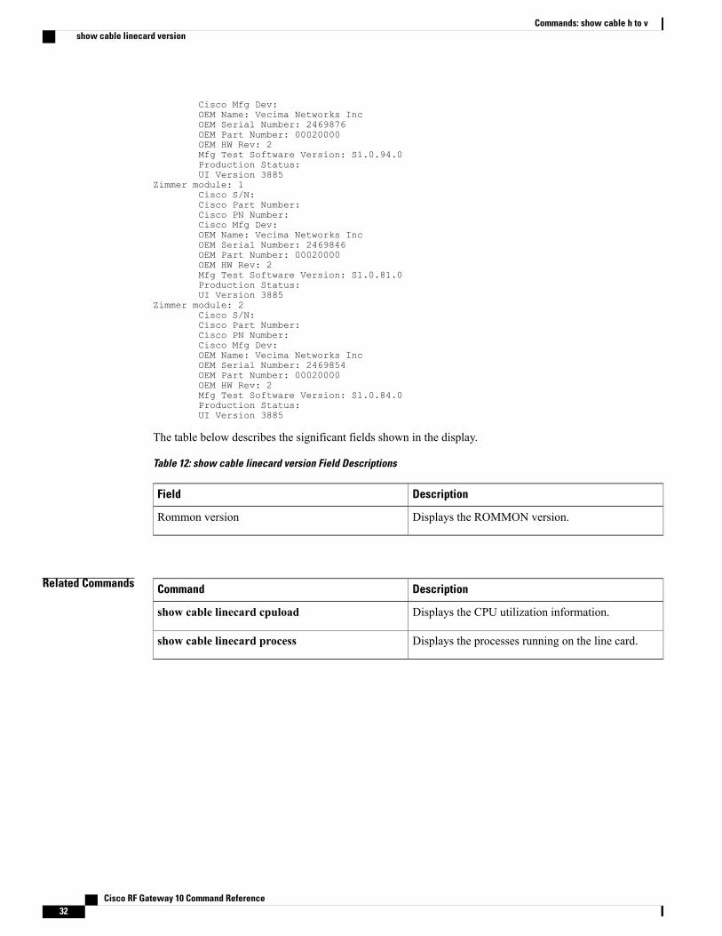
Cisco Mfg Dev:OEM Name: Vecima Networks IncOEM Serial Number: 2469876OEM Part Number: 00020000OEM HW Rev: 2Mfg Test Software Version: S1.0.94.0Production Status:UI Version 3885
Zimmer module: 1Cisco S/N:Cisco Part Number:Cisco PN Number:Cisco Mfg Dev:OEM Name: Vecima Networks IncOEM Serial Number: 2469846OEM Part Number: 00020000OEM HW Rev: 2Mfg Test Software Version: S1.0.81.0Production Status:UI Version 3885
Zimmer module: 2Cisco S/N:Cisco Part Number:Cisco PN Number:Cisco Mfg Dev:OEM Name: Vecima Networks IncOEM Serial Number: 2469854OEM Part Number: 00020000OEM HW Rev: 2Mfg Test Software Version: S1.0.84.0Production Status:UI Version 3885
The table below describes the significant fields shown in the display.
Table 12: show cable linecard version Field Descriptions
DescriptionField
Displays the ROMMON version.Rommon version
Related Commands DescriptionCommand
Displays the CPU utilization information.show cable linecard cpuload
Displays the processes running on the line card.show cable linecard process
Cisco RF Gateway 10 Command Reference32
Commands: show cable h to vshow cable linecard version
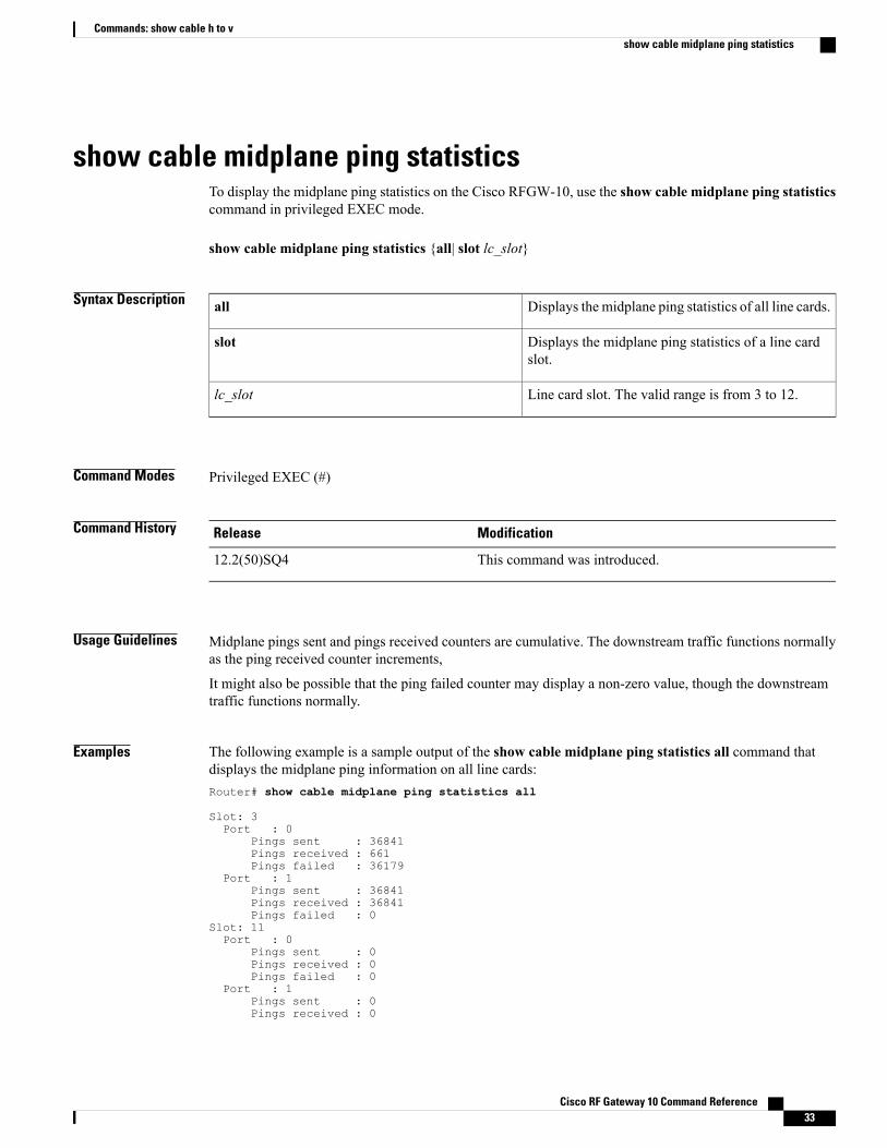
show cable midplane ping statisticsTo display the midplane ping statistics on the Cisco RFGW-10, use the show cable midplane ping statisticscommand in privileged EXEC mode.
show cable midplane ping statistics {all| slot lc_slot}
Syntax Description Displays the midplane ping statistics of all line cards.all
Displays the midplane ping statistics of a line cardslot.
slot
Line card slot. The valid range is from 3 to 12.lc_slot
Command Modes Privileged EXEC (#)
Command History ModificationRelease
This command was introduced.12.2(50)SQ4
Usage Guidelines Midplane pings sent and pings received counters are cumulative. The downstream traffic functions normallyas the ping received counter increments,
It might also be possible that the ping failed counter may display a non-zero value, though the downstreamtraffic functions normally.
Examples The following example is a sample output of the show cable midplane ping statistics all command thatdisplays the midplane ping information on all line cards:Router# show cable midplane ping statistics all
Slot: 3Port : 0
Pings sent : 36841Pings received : 661Pings failed : 36179
Port : 1Pings sent : 36841Pings received : 36841Pings failed : 0
Slot: 11Port : 0
Pings sent : 0Pings received : 0Pings failed : 0
Port : 1Pings sent : 0Pings received : 0
Cisco RF Gateway 10 Command Reference 33
Commands: show cable h to vshow cable midplane ping statistics
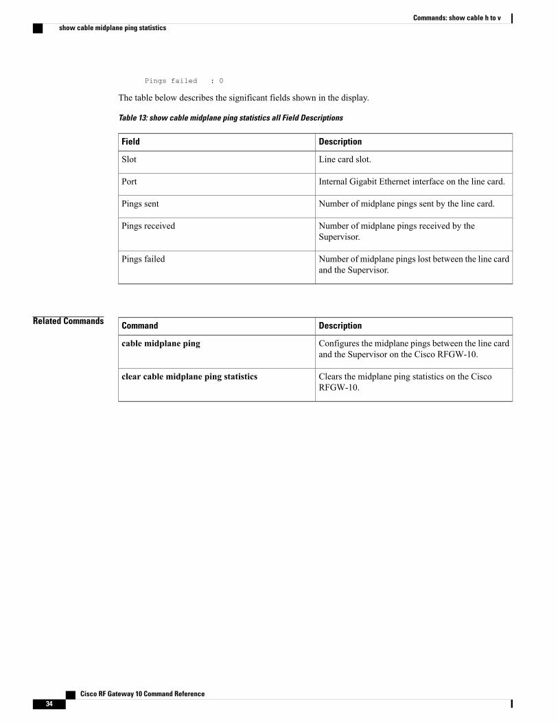
Pings failed : 0
The table below describes the significant fields shown in the display.
Table 13: show cable midplane ping statistics all Field Descriptions
DescriptionField
Line card slot.Slot
Internal Gigabit Ethernet interface on the line card.Port
Number of midplane pings sent by the line card.Pings sent
Number of midplane pings received by theSupervisor.
Pings received
Number of midplane pings lost between the line cardand the Supervisor.
Pings failed
Related Commands DescriptionCommand
Configures the midplane pings between the line cardand the Supervisor on the Cisco RFGW-10.
cable midplane ping
Clears the midplane ping statistics on the CiscoRFGW-10.
clear cable midplane ping statistics
Cisco RF Gateway 10 Command Reference34
Commands: show cable h to vshow cable midplane ping statistics
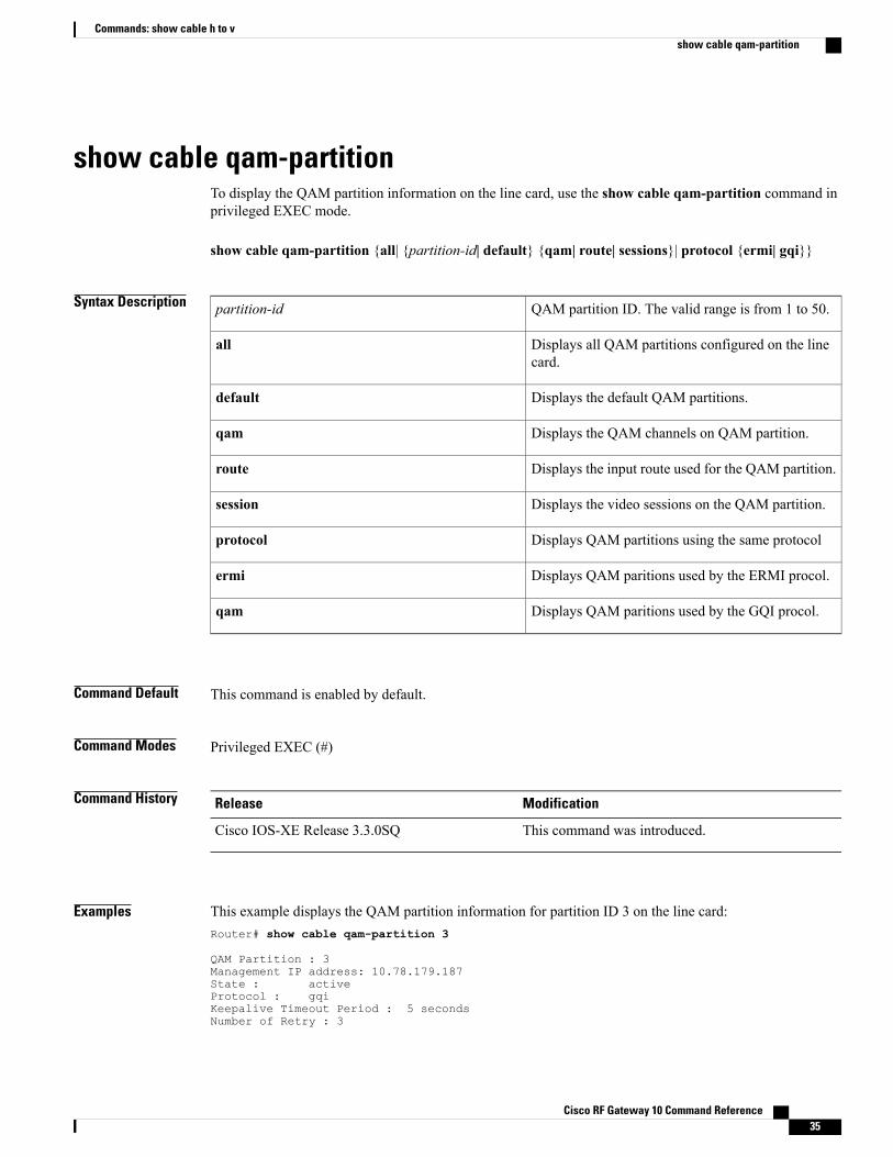
show cable qam-partitionTo display the QAM partition information on the line card, use the show cable qam-partition command inprivileged EXEC mode.
show cable qam-partition {all| {partition-id| default} {qam| route| sessions}| protocol {ermi| gqi}}
Syntax Description QAM partition ID. The valid range is from 1 to 50.partition-id
Displays all QAM partitions configured on the linecard.
all
Displays the default QAM partitions.default
Displays the QAM channels on QAM partition.qam
Displays the input route used for the QAM partition.route
Displays the video sessions on the QAM partition.session
Displays QAM partitions using the same protocolprotocol
Displays QAM paritions used by the ERMI procol.ermi
Displays QAM paritions used by the GQI procol.qam
Command Default This command is enabled by default.
Command Modes Privileged EXEC (#)
Command History ModificationRelease
This command was introduced.Cisco IOS-XE Release 3.3.0SQ
Examples This example displays the QAM partition information for partition ID 3 on the line card:Router# show cable qam-partition 3
QAM Partition : 3Management IP address: 10.78.179.187State : activeProtocol : gqiKeepalive Timeout Period : 5 secondsNumber of Retry : 3
Cisco RF Gateway 10 Command Reference 35
Commands: show cable h to vshow cable qam-partition
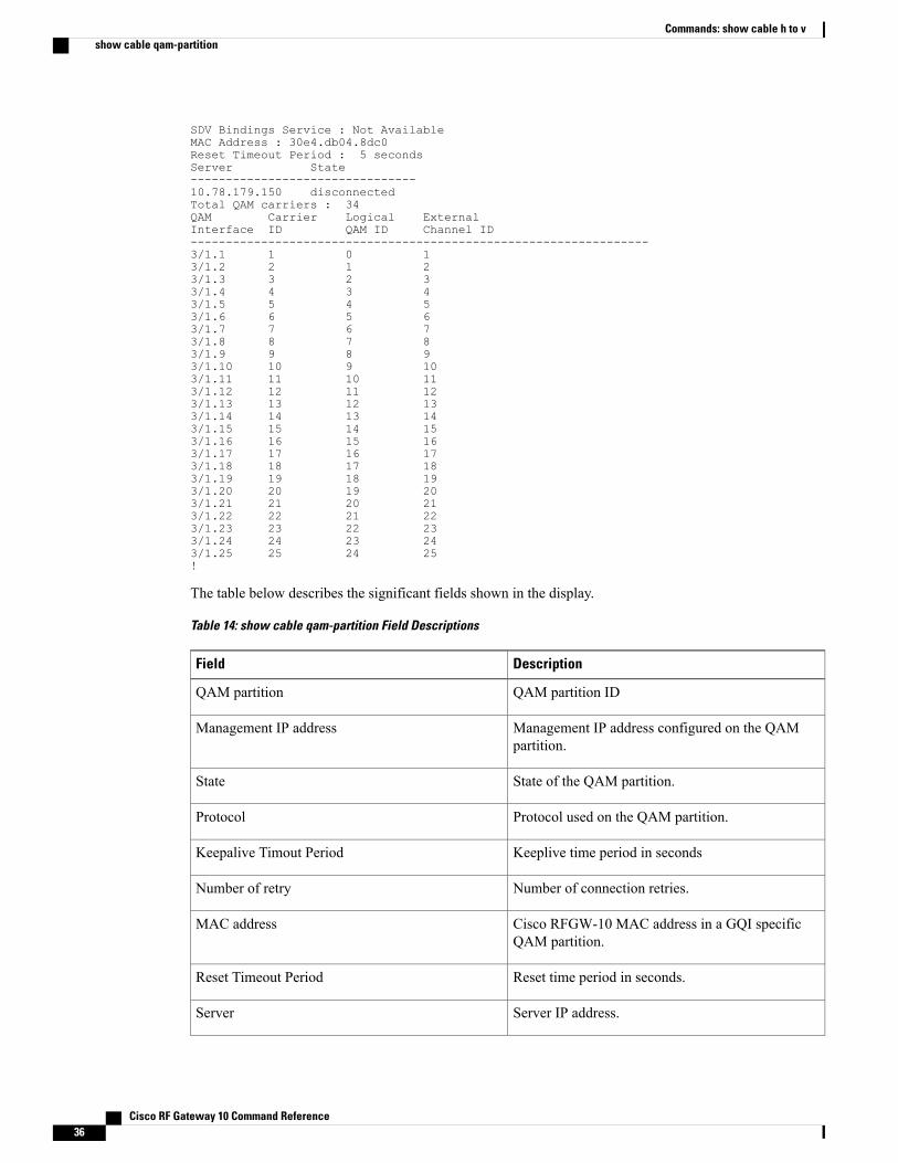
SDV Bindings Service : Not AvailableMAC Address : 30e4.db04.8dc0Reset Timeout Period : 5 secondsServer State--------------------------------10.78.179.150 disconnectedTotal QAM carriers : 34QAM Carrier Logical ExternalInterface ID QAM ID Channel ID-----------------------------------------------------------------3/1.1 1 0 13/1.2 2 1 23/1.3 3 2 33/1.4 4 3 43/1.5 5 4 53/1.6 6 5 63/1.7 7 6 73/1.8 8 7 83/1.9 9 8 93/1.10 10 9 103/1.11 11 10 113/1.12 12 11 123/1.13 13 12 133/1.14 14 13 143/1.15 15 14 153/1.16 16 15 163/1.17 17 16 173/1.18 18 17 183/1.19 19 18 193/1.20 20 19 203/1.21 21 20 213/1.22 22 21 223/1.23 23 22 233/1.24 24 23 243/1.25 25 24 25!
The table below describes the significant fields shown in the display.
Table 14: show cable qam-partition Field Descriptions
DescriptionField
QAM partition IDQAM partition
Management IP address configured on the QAMpartition.
Management IP address
State of the QAM partition.State
Protocol used on the QAM partition.Protocol
Keeplive time period in secondsKeepalive Timout Period
Number of connection retries.Number of retry
Cisco RFGW-10 MAC address in a GQI specificQAM partition.
MAC address
Reset time period in seconds.Reset Timeout Period
Server IP address.Server
Cisco RF Gateway 10 Command Reference36
Commands: show cable h to vshow cable qam-partition

DescriptionField
State of the video server.State
No of carriers on the QAM partition.Total QAM carriers
QAM interface associated with the QAM partition.QAM interface
QAM channel.Carrier ID
Logical QAM ID.Logical QAM ID
External channel number for GQI protocol QAMpartition.
External channel ID
This example displays the default QAM partition information for QAM channels on the line card:Router# show cable qam-partition default qam
QAM Partition : 0Total QAM carriers : 34QAM Carrier LogicalInterface ID QAM ID-----------------------------------------------------------------3/3.1 65 643/3.2 66 653/3.3 67 663/3.4 68 673/3.5 69 683/3.6 70 693/3.7 71 703/3.8 72 713/3.9 73 723/3.10 74 733/3.11 75 743/3.12 76 753/3.13 77 763/3.14 78 773/3.15 79 783/3.16 80 793/3.17 81 803/3.18 82 81This example displays the default QAM partition information for input routes used by the QAM partition:Router# show cable qam-partition default route
QAM Partition : 0Total Routes : 4Slot LBG Destination Low High Reserved Bandwidth Ingress NumbeId Id IP UDP UDP Bandwdith In-Use Port Sessis--------------------------------------------------------------------------------3 1 30.0.3.10 1 49260 1000000 3300 0 23 2 1.21.1.2 1 49260 1000000 0 0 03 2 40.0.1.10 1 65535 1000000 3300 0 27 1 192.168.11.2 1 65535 112500 0 0 0
The table below describes the significant fields shown in the display.
Cisco RF Gateway 10 Command Reference 37
Commands: show cable h to vshow cable qam-partition
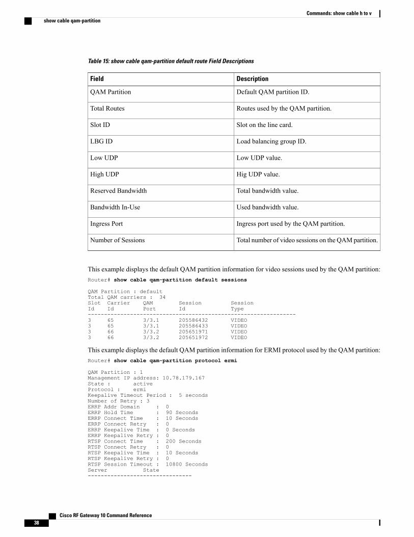
Table 15: show cable qam-partition default route Field Descriptions
DescriptionField
Default QAM partition ID.QAM Partition
Routes used by the QAM partition.Total Routes
Slot on the line card.Slot ID
Load balancing group ID.LBG ID
Low UDP value.Low UDP
Hig UDP value.High UDP
Total bandwidth value.Reserved Bandwidth
Used bandwidth value.Bandwidth In-Use
Ingress port used by the QAM partition.Ingress Port
Total number of video sessions on the QAMpartition.Number of Sessions
This example displays the default QAM partition information for video sessions used by the QAM partition:Router# show cable qam-partition default sessions
QAM Partition : defaultTotal QAM carriers : 34Slot Carrier QAM Session SessionId Id Port Id Type----------------------------------------------------------------3 65 3/3.1 205586432 VIDEO3 65 3/3.1 205586433 VIDEO3 66 3/3.2 205651971 VIDEO3 66 3/3.2 205651972 VIDEO
This example displays the default QAM partition information for ERMI protocol used by the QAM partition:Router# show cable qam-partition protocol ermi
QAM Partition : 1Management IP address: 10.78.179.167State : activeProtocol : ermiKeepalive Timeout Period : 5 secondsNumber of Retry : 3ERRP Addr Domain : 0ERRP Hold Time : 90 SecondsERRP Connect Time : 10 SecondsERRP Connect Retry : 0ERRP Keepalive Time : 0 SecondsERRP Keepalive Retry : 0RTSP Connect Time : 200 SecondsRTSP Connect Retry : 0RTSP Keepalive Time : 10 SecondsRTSP Keepalive Retry : 0RTSP Session Timeout : 10800 SecondsServer State--------------------------------
Cisco RF Gateway 10 Command Reference38
Commands: show cable h to vshow cable qam-partition
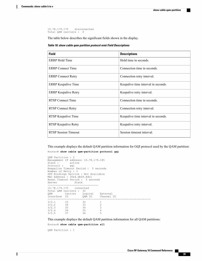
10.78.179.170 disconnectedTotal QAM carriers : 0
The table below describes the significant fields shown in the display.
Table 16: show cable qam-partition protocol ermi Field Descriptions
DescriptionsField
Hold time in seconds.ERRP Hold Time
Connection time in seconds.ERRP Connect Time
Connection retry interval.ERRP Connect Retry
Keepalive time interval in seconds.ERRP Keepalive Time
Keepalive retry interval.ERRP Keepalive Retry
Connection time in seconds.RTSP Connect Time
Connection retry interval.RTSP Connect Retry
Keepalive time interval in seconds.RTSP Keepalive Time
Keepalive retry interval.RTSP Keepalive Retry
Session timeout interval.RTSP Session Timeout
This example displays the default QAM partition information for GQI protocol used by the QAM partition:Router# show cable qam-partition protocol gqi
QAM Partition : 2Management IP address: 10.78.179.185State : activeProtocol : gqiKeepalive Timeout Period : 5 secondsNumber of Retry : 3SDV Bindings Service : Not AvailableMAC Address : 30e4.db04.8dc1Reset Timeout Period : 5 secondsServer State--------------------------------10.78.179.170 connectedTotal QAM carriers : 32QAM Carrier Logical ExternalInterface ID QAM ID Channel ID-----------------------------------------------------------------3/2.1 33 32 13/2.2 34 33 23/2.3 35 34 33/2.4 36 35 43/2.5 37 36 5
This example displays the default QAM partition information for all QAM partitions:Router# show cable qam-partition all
QAM Partition : 1
Cisco RF Gateway 10 Command Reference 39
Commands: show cable h to vshow cable qam-partition

Management IP address: 10.78.179.167State : activeProtocol : ermiKeepalive Timeout Period : 5 secondsNumber of Retry : 3ERRP Addr Domain : 0ERRP Hold Time : 90 SecondsERRP Connect Time : 10 SecondsERRP Connect Retry : 0ERRP Keepalive Time : 0 SecondsERRP Keepalive Retry : 0RTSP Connect Time : 200 SecondsRTSP Connect Retry : 0RTSP Keepalive Time : 10 SecondsRTSP Keepalive Retry : 0RTSP Session Timeout : 10800 SecondsServer State--------------------------------10.78.179.170 disconnectedTotal QAM carriers : 0Total Routes: 1Slot LBG Destination Low High Reserved Bandwidth Ingress NumbId Id IP UDP UDP Bandwdith In-Use Port Sesss-------------------------------------------------------------------------------3 1 1.1.1.1 1 65535 21 0 0 0QAM Partition : 2Management IP address: 10.78.179.185State : activeProtocol : gqiKeepalive Timeout Period : 5 secondsNumber of Retry : 3SDV Bindings Service : Not AvailableMAC Address : 30e4.db04.8dc1Reset Timeout Period : 5 secondsServer State--------------------------------10.78.179.170 connectedTotal QAM carriers : 32QAM Carrier Logical ExternalInterface ID QAM ID Channel ID-----------------------------------------------------------------3/2.1 33 32 13/2.2 34 33 23/2.3 35 34 33/2.4 36 35 43/2.5 37 36 53/2.6 38 37 63/2.7 39 38 73/2.8 40 39 83/2.9 41 40 93/2.10 42 41 103/2.11 43 42 113/2.12 44 43 123/2.13 45 44 133/2.14 46 45 143/2.15 47 46 153/2.16 48 47 163/2.17 49 48 173/2.18 50 49 183/2.19 51 50 193/2.20 52 51 203/2.21 53 52 213/2.22 54 53 223/2.23 55 54 233/2.24 56 55 243/2.25 57 56 253/2.26 58 57 263/2.27 59 58 273/2.28 60 59 283/2.29 61 60 293/2.30 62 61 30
Cisco RF Gateway 10 Command Reference40
Commands: show cable h to vshow cable qam-partition
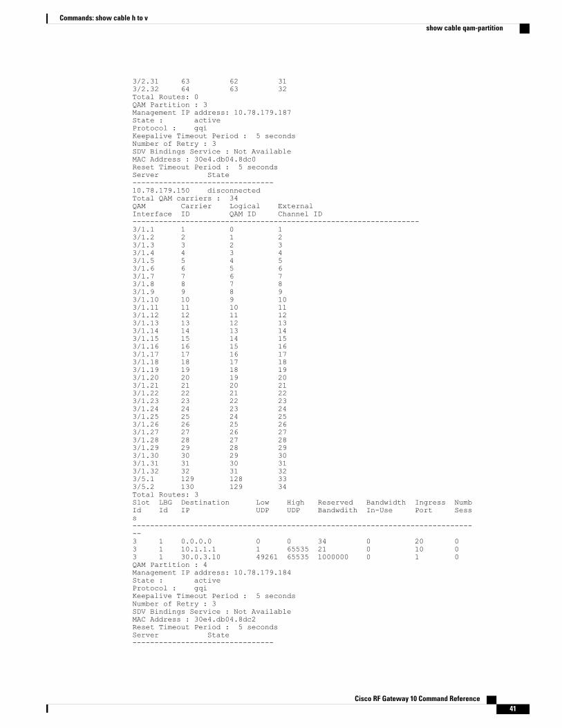
3/2.31 63 62 313/2.32 64 63 32Total Routes: 0QAM Partition : 3Management IP address: 10.78.179.187State : activeProtocol : gqiKeepalive Timeout Period : 5 secondsNumber of Retry : 3SDV Bindings Service : Not AvailableMAC Address : 30e4.db04.8dc0Reset Timeout Period : 5 secondsServer State--------------------------------10.78.179.150 disconnectedTotal QAM carriers : 34QAM Carrier Logical ExternalInterface ID QAM ID Channel ID-----------------------------------------------------------------3/1.1 1 0 13/1.2 2 1 23/1.3 3 2 33/1.4 4 3 43/1.5 5 4 53/1.6 6 5 63/1.7 7 6 73/1.8 8 7 83/1.9 9 8 93/1.10 10 9 103/1.11 11 10 113/1.12 12 11 123/1.13 13 12 133/1.14 14 13 143/1.15 15 14 153/1.16 16 15 163/1.17 17 16 173/1.18 18 17 183/1.19 19 18 193/1.20 20 19 203/1.21 21 20 213/1.22 22 21 223/1.23 23 22 233/1.24 24 23 243/1.25 25 24 253/1.26 26 25 263/1.27 27 26 273/1.28 28 27 283/1.29 29 28 293/1.30 30 29 303/1.31 31 30 313/1.32 32 31 323/5.1 129 128 333/5.2 130 129 34Total Routes: 3Slot LBG Destination Low High Reserved Bandwidth Ingress NumbId Id IP UDP UDP Bandwdith In-Use Port Sesss-------------------------------------------------------------------------------3 1 0.0.0.0 0 0 34 0 20 03 1 10.1.1.1 1 65535 21 0 10 03 1 30.0.3.10 49261 65535 1000000 0 1 0QAM Partition : 4Management IP address: 10.78.179.184State : activeProtocol : gqiKeepalive Timeout Period : 5 secondsNumber of Retry : 3SDV Bindings Service : Not AvailableMAC Address : 30e4.db04.8dc2Reset Timeout Period : 5 secondsServer State--------------------------------
Cisco RF Gateway 10 Command Reference 41
Commands: show cable h to vshow cable qam-partition
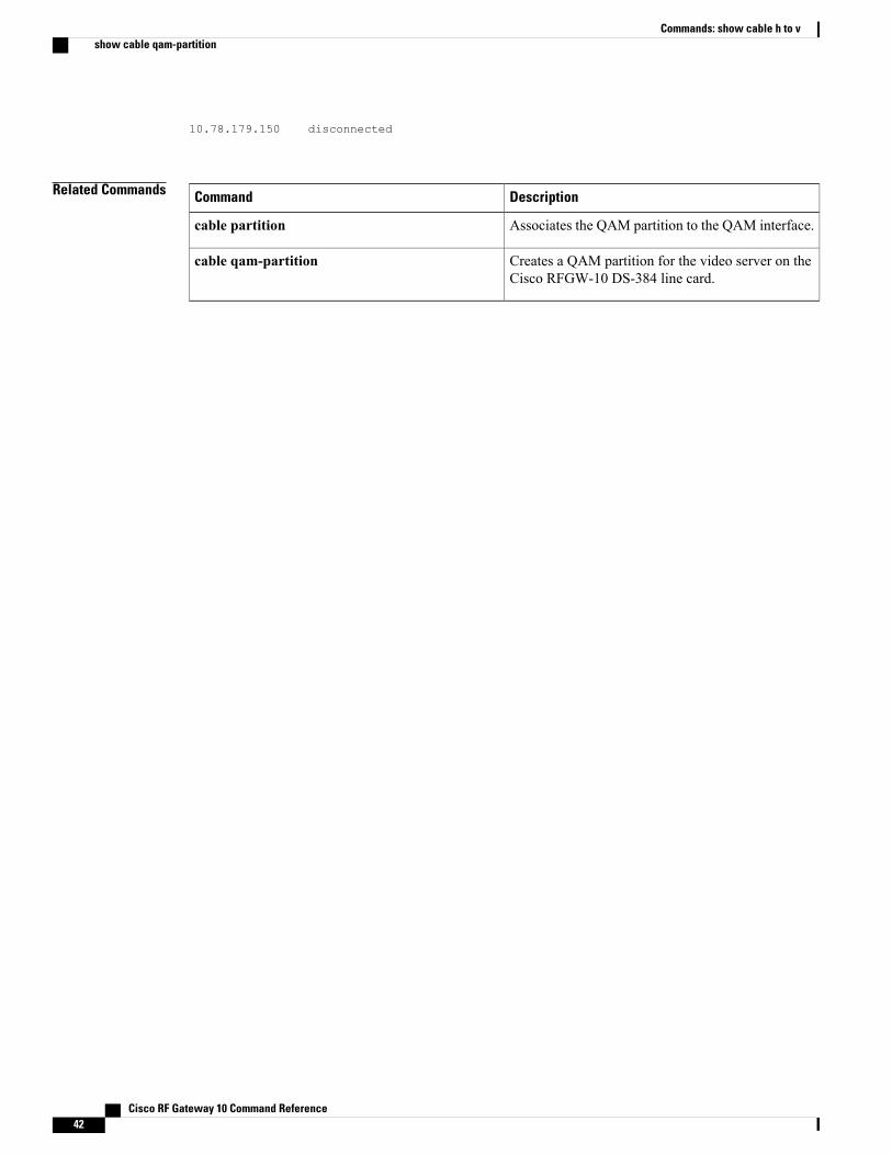
10.78.179.150 disconnected
Related Commands DescriptionCommand
Associates the QAM partition to the QAM interface.cable partition
Creates a QAM partition for the video server on theCisco RFGW-10 DS-384 line card.
cable qam-partition
Cisco RF Gateway 10 Command Reference42
Commands: show cable h to vshow cable qam-partition
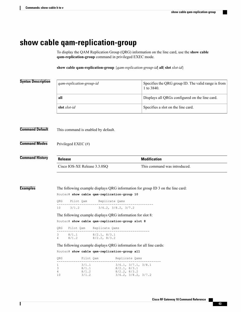
show cable qam-replication-groupTo display the QAM Replication Group (QRG) information on the line card, use the show cableqam-replication-group command in privileged EXEC mode.
show cable qam-replication-group {qam-replication-group-id| all| slot slot-id}
Syntax Description Specifies the QRG group ID. The valid range is from1 to 3840.
qam-replication-group-id
Displays all QRGs configured on the line card.all
Specifies a slot on the line card.slot slot-id
Command Default This command is enabled by default.
Command Modes Privileged EXEC (#)
Command History ModificationRelease
This command was introduced.Cisco IOS-XE Release 3.3.0SQ
Examples The following example displays QRG information for group ID 3 on the line card:Router# show cable qam-replication-group 10
QRG Pilot Qam Replicate Qams---------------------------------------------------10 3/1.2 3/6.2, 3/8.2, 3/7.2
The following example displays QRG information for slot 8:Router# show cable qam-replication-group slot 8
QRG Pilot Qam Replicate Qams-------------------------------------------------3 8/1.1 8/2.1, 8/3.14 8/1.2 8/2.2, 8/3.2
The following example displays QRG information for all line cards:Router# show cable qam-replication-group all
QRG Pilot Qam Replicate Qams-------------------------------------------------------1 3/1.1 3/6.1, 3/7.1, 3/8.13 8/1.1 8/2.1, 8/3.14 8/1.2 8/2.2, 8/3.210 3/1.2 3/6.2, 3/8.2, 3/7.2
Cisco RF Gateway 10 Command Reference 43
Commands: show cable h to vshow cable qam-replication-group
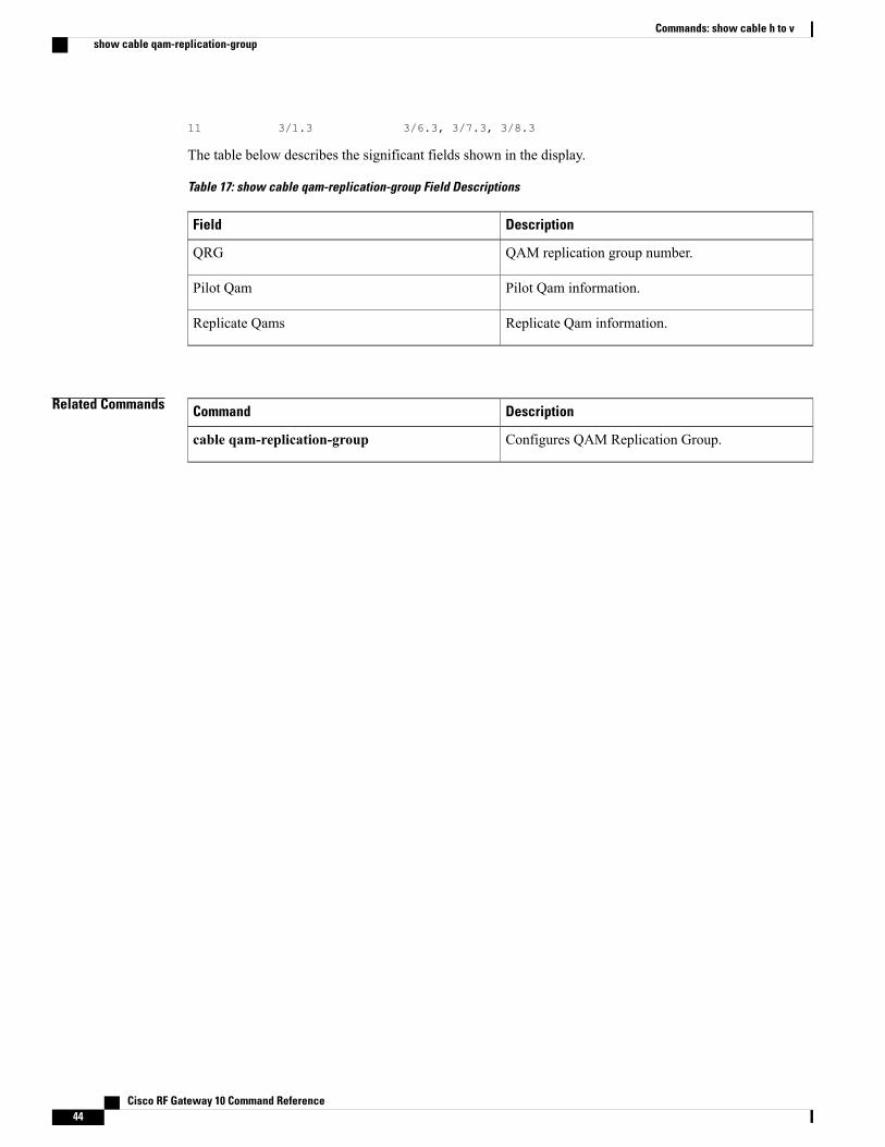
11 3/1.3 3/6.3, 3/7.3, 3/8.3
The table below describes the significant fields shown in the display.
Table 17: show cable qam-replication-group Field Descriptions
DescriptionField
QAM replication group number.QRG
Pilot Qam information.Pilot Qam
Replicate Qam information.Replicate Qams
Related Commands DescriptionCommand
Configures QAM Replication Group.cable qam-replication-group
Cisco RF Gateway 10 Command Reference44
Commands: show cable h to vshow cable qam-replication-group
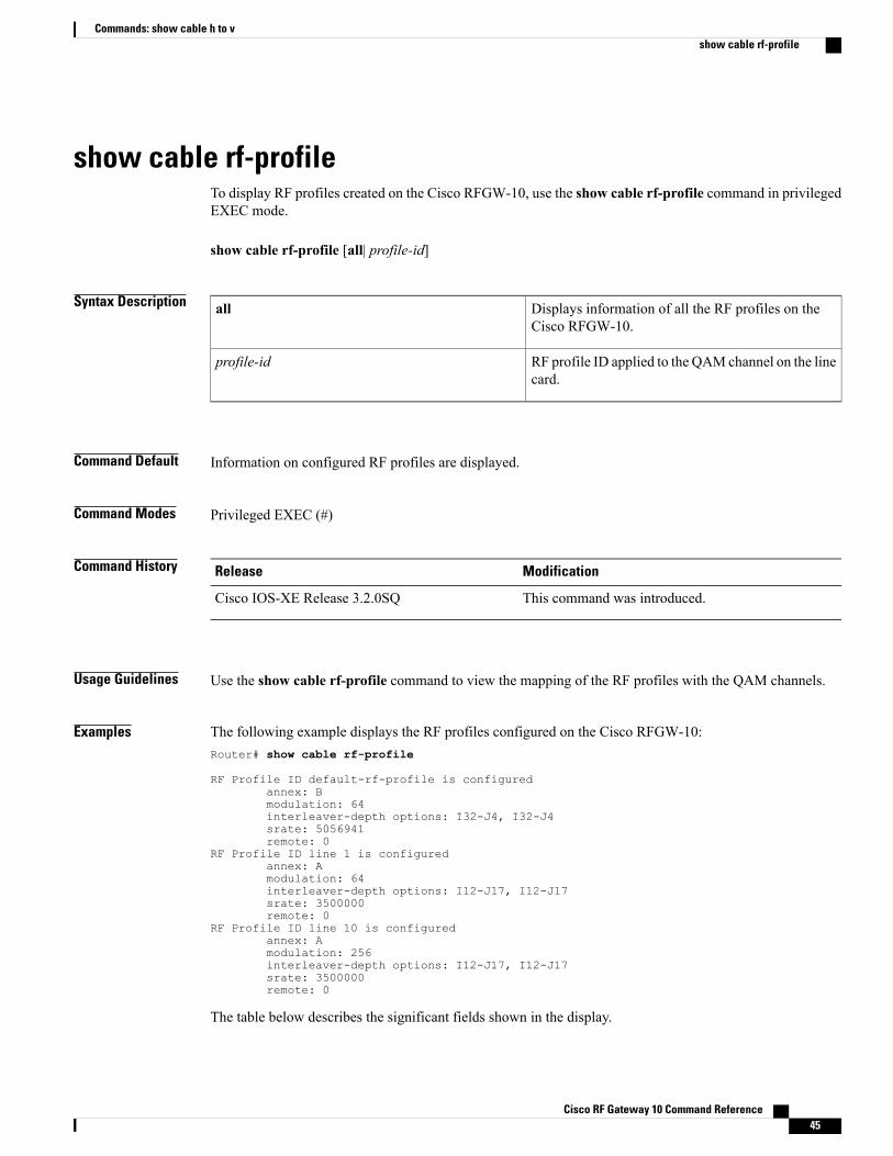
show cable rf-profileTo display RF profiles created on the Cisco RFGW-10, use the show cable rf-profile command in privilegedEXEC mode.
show cable rf-profile [all| profile-id]
Syntax Description Displays information of all the RF profiles on theCisco RFGW-10.
all
RF profile ID applied to the QAM channel on the linecard.
profile-id
Command Default Information on configured RF profiles are displayed.
Command Modes Privileged EXEC (#)
Command History ModificationRelease
This command was introduced.Cisco IOS-XE Release 3.2.0SQ
Usage Guidelines Use the show cable rf-profile command to view the mapping of the RF profiles with the QAM channels.
Examples The following example displays the RF profiles configured on the Cisco RFGW-10:Router# show cable rf-profile
RF Profile ID default-rf-profile is configuredannex: Bmodulation: 64interleaver-depth options: I32-J4, I32-J4srate: 5056941remote: 0
RF Profile ID line 1 is configuredannex: Amodulation: 64interleaver-depth options: I12-J17, I12-J17srate: 3500000remote: 0
RF Profile ID line 10 is configuredannex: Amodulation: 256interleaver-depth options: I12-J17, I12-J17srate: 3500000remote: 0
The table below describes the significant fields shown in the display.
Cisco RF Gateway 10 Command Reference 45
Commands: show cable h to vshow cable rf-profile
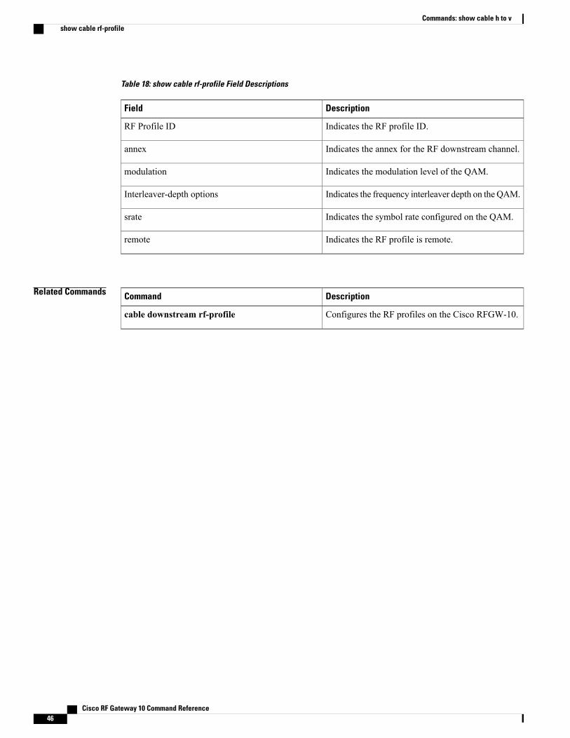
Table 18: show cable rf-profile Field Descriptions
DescriptionField
Indicates the RF profile ID.RF Profile ID
Indicates the annex for the RF downstream channel.annex
Indicates the modulation level of the QAM.modulation
Indicates the frequency interleaver depth on theQAM.Interleaver-depth options
Indicates the symbol rate configured on the QAM.srate
Indicates the RF profile is remote.remote
Related Commands DescriptionCommand
Configures the RF profiles on the Cisco RFGW-10.cable downstream rf-profile
Cisco RF Gateway 10 Command Reference46
Commands: show cable h to vshow cable rf-profile
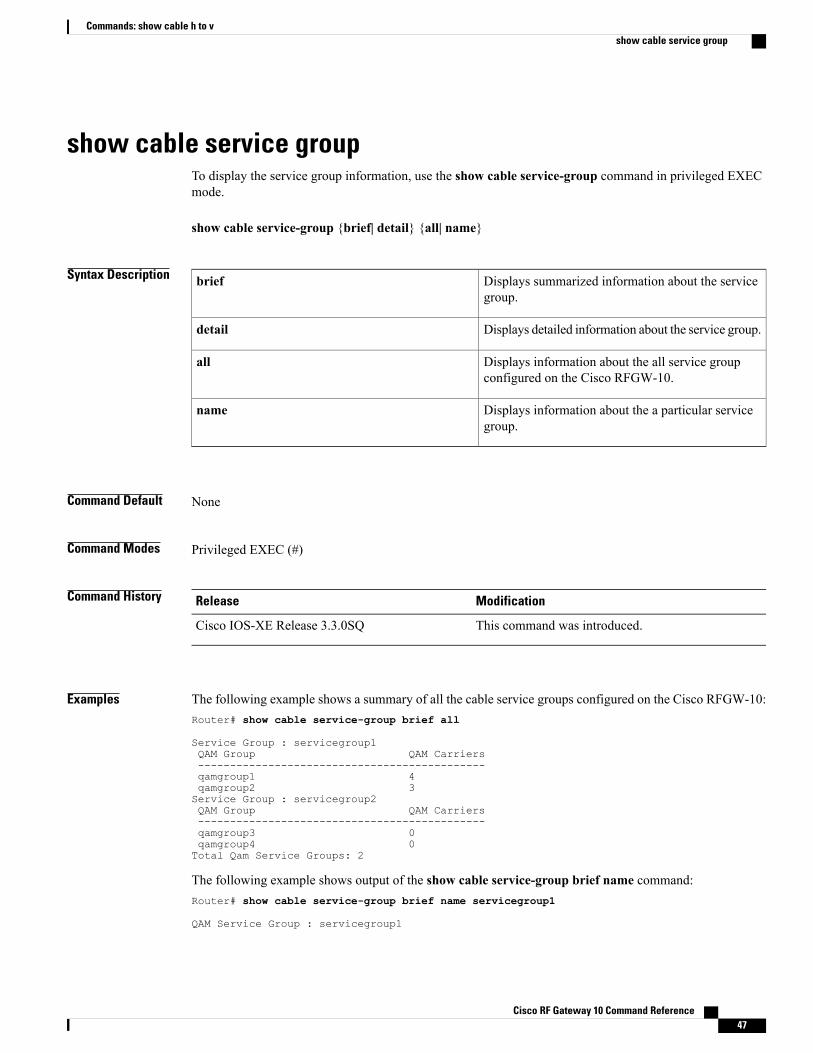
show cable service groupTo display the service group information, use the show cable service-group command in privileged EXECmode.
show cable service-group {brief| detail} {all| name}
Syntax Description Displays summarized information about the servicegroup.
brief
Displays detailed information about the service group.detail
Displays information about the all service groupconfigured on the Cisco RFGW-10.
all
Displays information about the a particular servicegroup.
name
Command Default None
Command Modes Privileged EXEC (#)
Command History ModificationRelease
This command was introduced.Cisco IOS-XE Release 3.3.0SQ
Examples The following example shows a summary of all the cable service groups configured on the Cisco RFGW-10:Router# show cable service-group brief all
Service Group : servicegroup1QAM Group QAM Carriers---------------------------------------------qamgroup1 4qamgroup2 3Service Group : servicegroup2QAM Group QAM Carriers---------------------------------------------qamgroup3 0qamgroup4 0Total Qam Service Groups: 2
The following example shows output of the show cable service-group brief name command:Router# show cable service-group brief name servicegroup1
QAM Service Group : servicegroup1
Cisco RF Gateway 10 Command Reference 47
Commands: show cable h to vshow cable service group
QAM Group QAM Carriers-----------------------------------------------qamgroup1 4qamgroup2 3
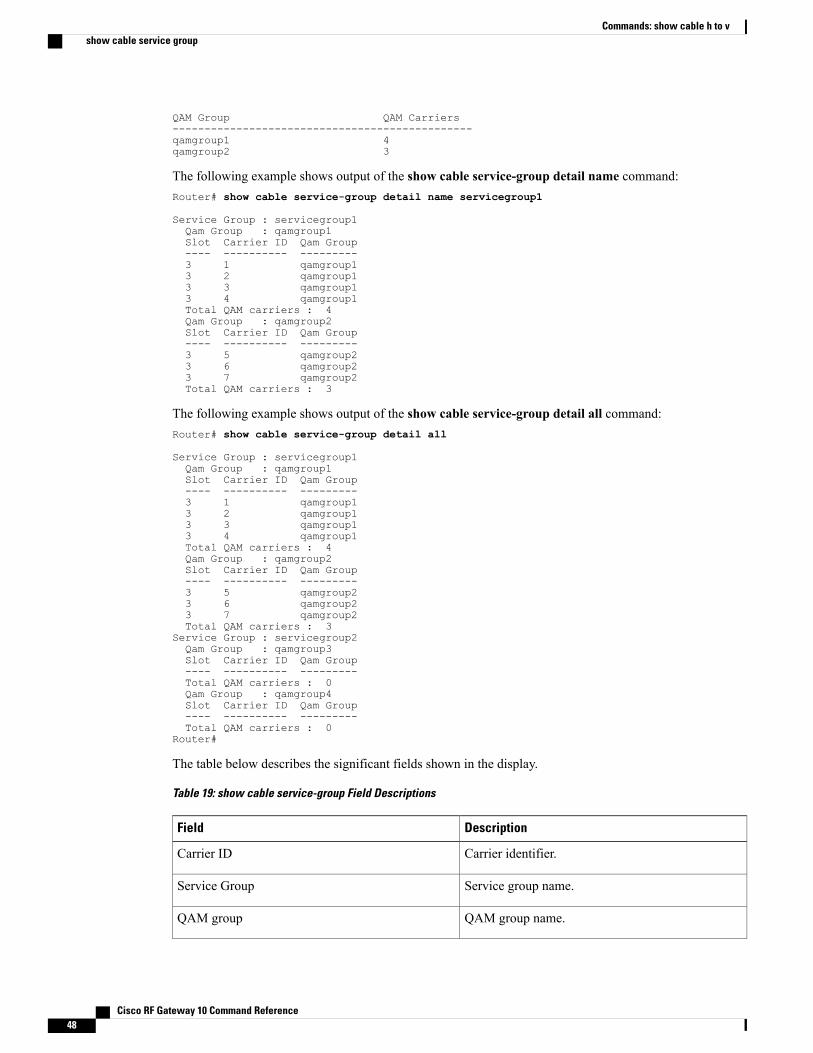
The following example shows output of the show cable service-group detail name command:Router# show cable service-group detail name servicegroup1
Service Group : servicegroup1Qam Group : qamgroup1Slot Carrier ID Qam Group---- ---------- ---------3 1 qamgroup13 2 qamgroup13 3 qamgroup13 4 qamgroup1Total QAM carriers : 4Qam Group : qamgroup2Slot Carrier ID Qam Group---- ---------- ---------3 5 qamgroup23 6 qamgroup23 7 qamgroup2Total QAM carriers : 3
The following example shows output of the show cable service-group detail all command:Router# show cable service-group detail all
Service Group : servicegroup1Qam Group : qamgroup1Slot Carrier ID Qam Group---- ---------- ---------3 1 qamgroup13 2 qamgroup13 3 qamgroup13 4 qamgroup1Total QAM carriers : 4Qam Group : qamgroup2Slot Carrier ID Qam Group---- ---------- ---------3 5 qamgroup23 6 qamgroup23 7 qamgroup2Total QAM carriers : 3
Service Group : servicegroup2Qam Group : qamgroup3Slot Carrier ID Qam Group---- ---------- ---------Total QAM carriers : 0Qam Group : qamgroup4Slot Carrier ID Qam Group---- ---------- ---------Total QAM carriers : 0
Router#
The table below describes the significant fields shown in the display.
Table 19: show cable service-group Field Descriptions
DescriptionField
Carrier identifier.Carrier ID
Service group name.Service Group
QAM group name.QAM group
Cisco RF Gateway 10 Command Reference48
Commands: show cable h to vshow cable service group
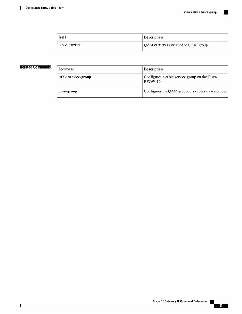
DescriptionField
QAM carriers associated to QAM group.QAM carriers
Related Commands DescriptionCommand
Configures a cable service group on the CiscoRFGW-10.
cable service-group
Configures the QAM group in a cable service group.qam-group
Cisco RF Gateway 10 Command Reference 49
Commands: show cable h to vshow cable service group
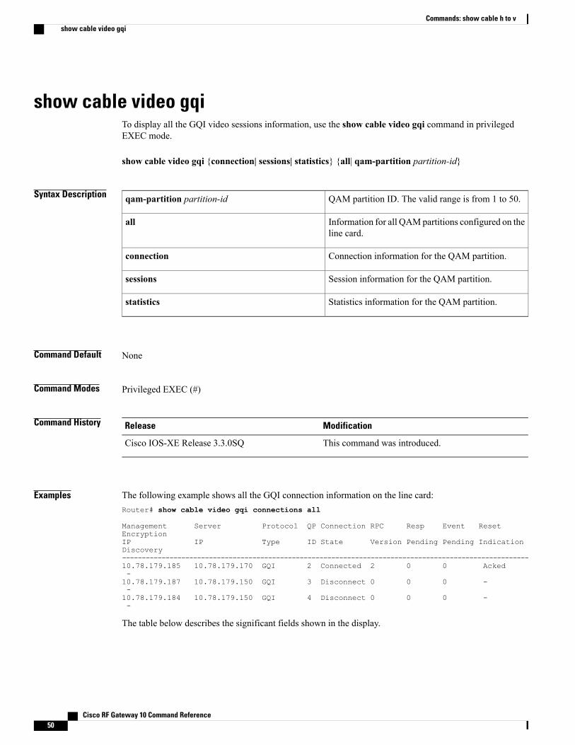
show cable video gqiTo display all the GQI video sessions information, use the show cable video gqi command in privilegedEXEC mode.
show cable video gqi {connection| sessions| statistics} {all| qam-partition partition-id}
Syntax Description QAM partition ID. The valid range is from 1 to 50.qam-partition partition-id
Information for all QAMpartitions configured on theline card.
all
Connection information for the QAM partition.connection
Session information for the QAM partition.sessions
Statistics information for the QAM partition.statistics
Command Default None
Command Modes Privileged EXEC (#)
Command History ModificationRelease
This command was introduced.Cisco IOS-XE Release 3.3.0SQ
Examples The following example shows all the GQI connection information on the line card:Router# show cable video gqi connections all
Management Server Protocol QP Connection RPC Resp Event ResetEncryptionIP IP Type ID State Version Pending Pending IndicationDiscovery-------------------------------------------------------------------------------------------------------10.78.179.185 10.78.179.170 GQI 2 Connected 2 0 0 Acked-10.78.179.187 10.78.179.150 GQI 3 Disconnect 0 0 0 --10.78.179.184 10.78.179.150 GQI 4 Disconnect 0 0 0 --
The table below describes the significant fields shown in the display.
Cisco RF Gateway 10 Command Reference50
Commands: show cable h to vshow cable video gqi
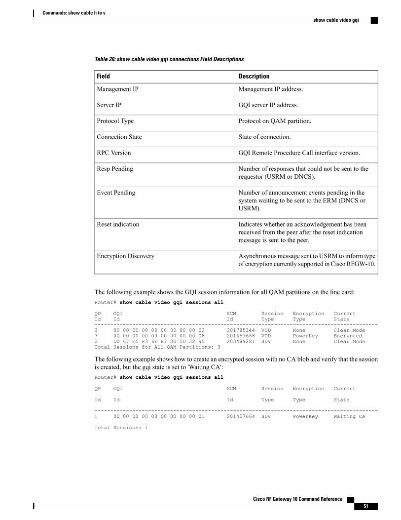
Table 20: show cable video gqi connections Field Descriptions
DescriptionField
Management IP address.Management IP
GQI server IP address.Server IP
Protocol on QAM partition.Protocol Type
State of connection.Connection State
GQI Remote Procedure Call interface version.RPC Version
Number of responses that could not be sent to therequestor (USRM or DNCS).
Resp Pending
Number of announcement events pending in thesystem waiting to be sent to the ERM (DNCS orUSRM).
Event Pending
Indicates whether an acknowledgement has beenreceived from the peer after the reset indicationmessage is sent to the peer.
Reset indication
Asynchronousmessage sent to USRM to inform typeof encryption currently supported in Cisco RFGW-10.
Encryption Discovery
The following example shows the GQI session information for all QAM partitions on the line card:Router# show cable video gqi sessions all
QP GQI SCM Session Encryption CurrentId Id Id Type Type State------------------------------------------------------------------------------------------3 00 00 00 00 00 00 00 00 00 03 201785344 VOD None Clear Mode3 00 00 00 00 00 00 00 00 00 08 201457668 VOD PowerKey Encrypted2 D0 67 E5 F3 6E E7 00 5D 32 95 203489281 SDV None Clear ModeTotal Sessions for All QAM Partitions: 3
The following example shows how to create an encrypted session with no CA blob and verify that the sessionis created, but the gqi state is set to 'Waiting CA':Router# show cable video gqi sessions all
QP GQI SCM Session Encryption Current
Id Id Id Type Type State
------------------------------------------------------------------------------------------1 00 00 00 00 00 00 00 00 00 01 201457664 SDV PowerKey Waiting CA
Total Sessions: 1
Cisco RF Gateway 10 Command Reference 51
Commands: show cable h to vshow cable video gqi
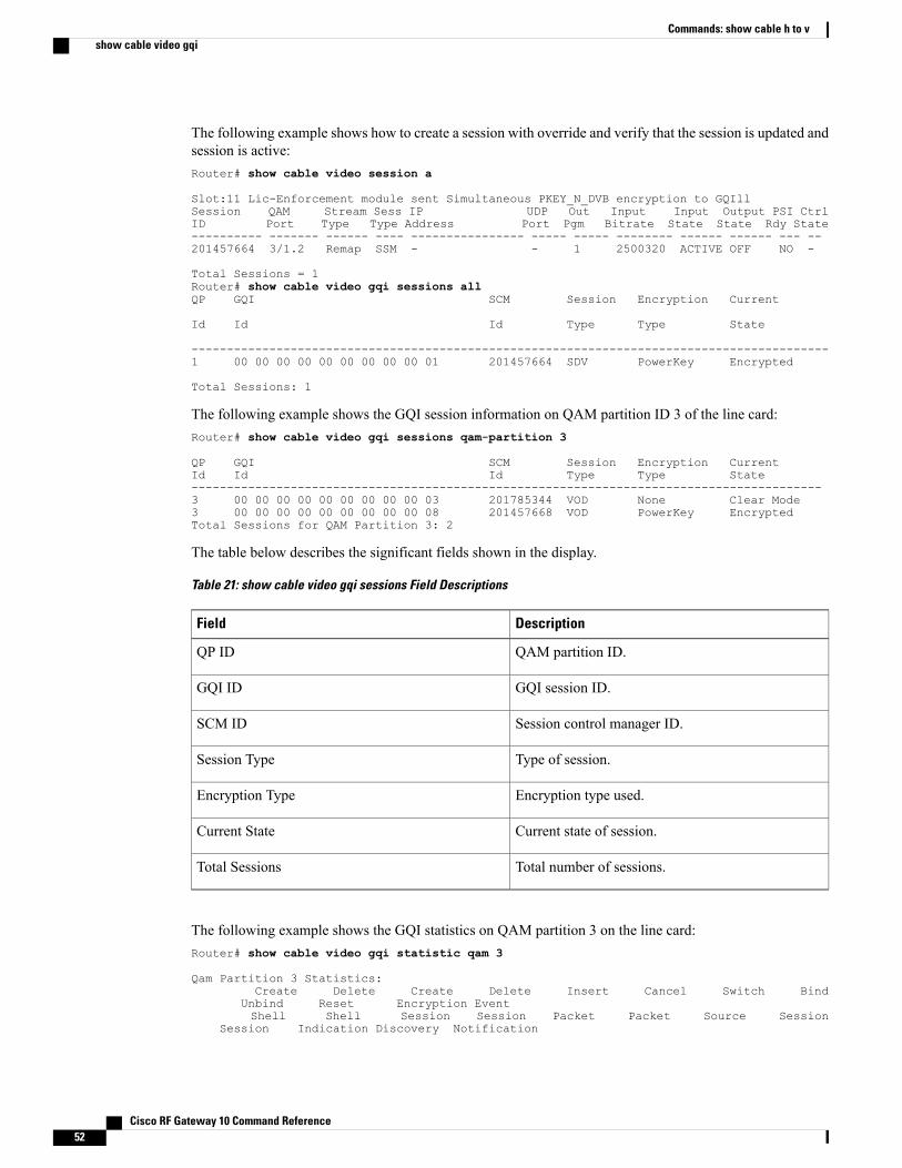
The following example shows how to create a session with override and verify that the session is updated andsession is active:Router# show cable video session a
Slot:11 Lic-Enforcement module sent Simultaneous PKEY_N_DVB encryption to GQIllSession QAM Stream Sess IP UDP Out Input Input Output PSI CtrlID Port Type Type Address Port Pgm Bitrate State State Rdy State---------- ------- ------ ---- ---------------- ----- ----- -------- ------ ------ --- --201457664 3/1.2 Remap SSM - - 1 2500320 ACTIVE OFF NO -
Total Sessions = 1Router# show cable video gqi sessions allQP GQI SCM Session Encryption Current
Id Id Id Type Type State
------------------------------------------------------------------------------------------1 00 00 00 00 00 00 00 00 00 01 201457664 SDV PowerKey Encrypted
Total Sessions: 1
The following example shows the GQI session information on QAM partition ID 3 of the line card:Router# show cable video gqi sessions qam-partition 3
QP GQI SCM Session Encryption CurrentId Id Id Type Type State-----------------------------------------------------------------------------------------3 00 00 00 00 00 00 00 00 00 03 201785344 VOD None Clear Mode3 00 00 00 00 00 00 00 00 00 08 201457668 VOD PowerKey EncryptedTotal Sessions for QAM Partition 3: 2
The table below describes the significant fields shown in the display.
Table 21: show cable video gqi sessions Field Descriptions
DescriptionField
QAM partition ID.QP ID
GQI session ID.GQI ID
Session control manager ID.SCM ID
Type of session.Session Type
Encryption type used.Encryption Type
Current state of session.Current State
Total number of sessions.Total Sessions
The following example shows the GQI statistics on QAM partition 3 on the line card:Router# show cable video gqi statistic qam 3
Qam Partition 3 Statistics:Create Delete Create Delete Insert Cancel Switch Bind
Unbind Reset Encryption EventShell Shell Session Session Packet Packet Source Session
Session Indication Discovery Notification
Cisco RF Gateway 10 Command Reference52
Commands: show cable h to vshow cable video gqi
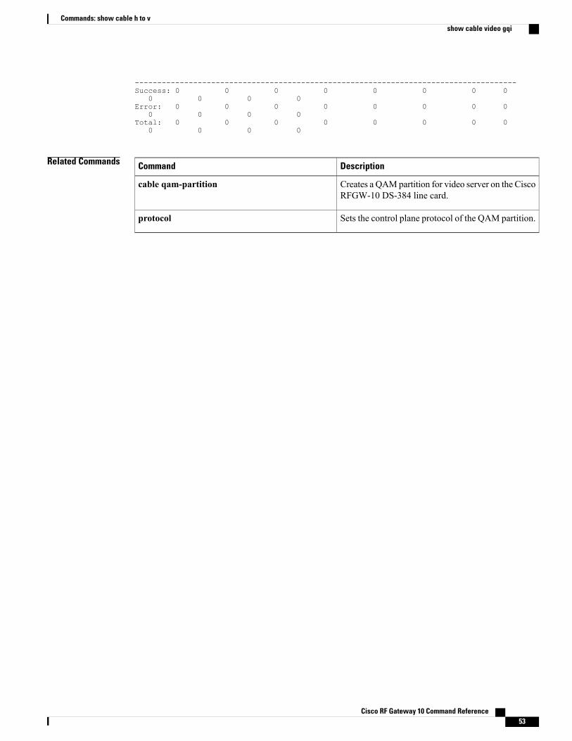
-------------------------------------------------------------------------------------Success: 0 0 0 0 0 0 0 0
0 0 0 0Error: 0 0 0 0 0 0 0 0
0 0 0 0Total: 0 0 0 0 0 0 0 0
0 0 0 0
Related Commands DescriptionCommand
Creates a QAMpartition for video server on the CiscoRFGW-10 DS-384 line card.
cable qam-partition
Sets the control plane protocol of the QAM partition.protocol
Cisco RF Gateway 10 Command Reference 53
Commands: show cable h to vshow cable video gqi
show cable video labelTo display the active video labels, use the show cable video label command in privileged EXEC mode.
show cable video label [ label ]
Syntax Description (Optional) Specifies the label name given to the videolabel.
label
Command Default None
Command Modes Privileged EXEC (#)
Usage Guidelines The command displays all the labels configured on the chassis.
Command History ModificationRelease
This command was introduced on the Cisco RF Gateway 10.12.2(44)SQ
The output of the command is modified to display the filtered PIDs forpass-through video sessions.
12.2(50)SQ1
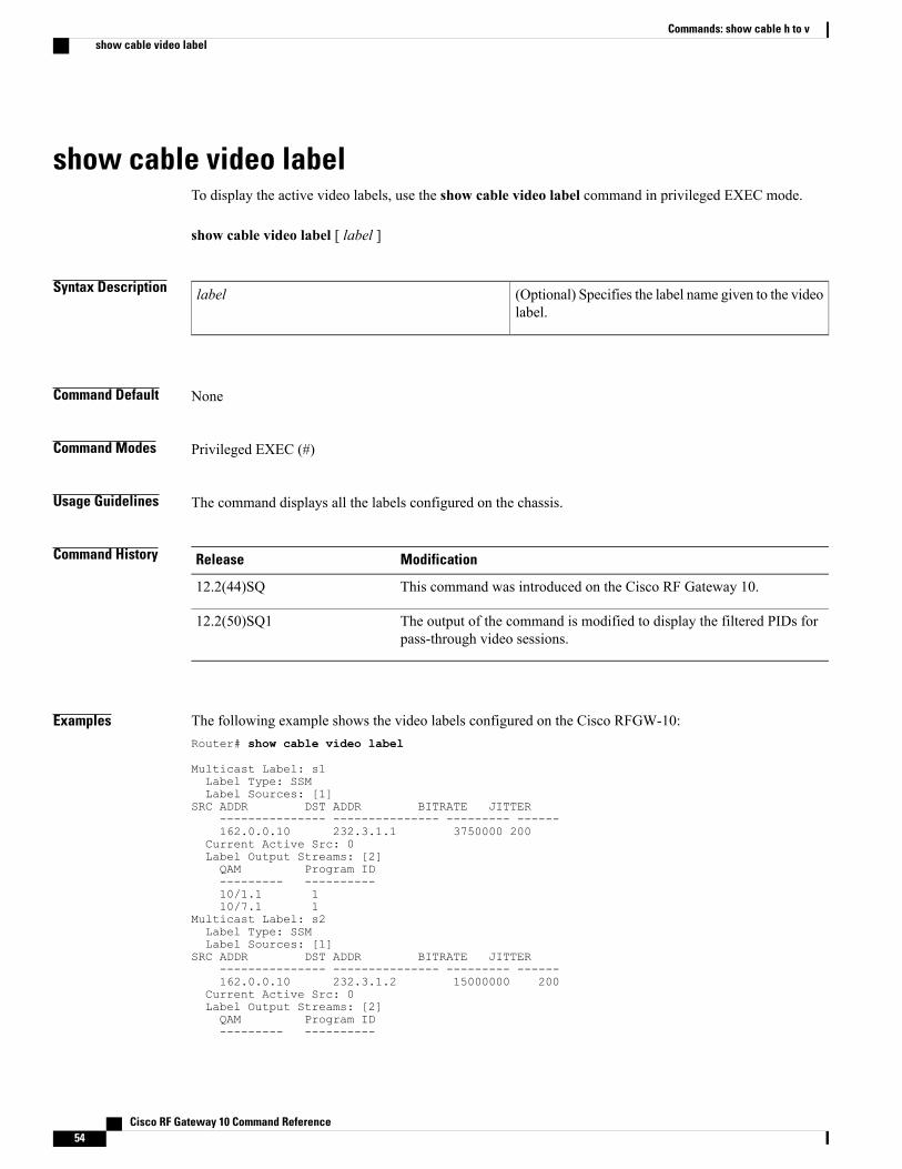
Examples The following example shows the video labels configured on the Cisco RFGW-10:Router# show cable video label
Multicast Label: s1Label Type: SSMLabel Sources: [1]
SRC ADDR DST ADDR BITRATE JITTER--------------- --------------- --------- ------162.0.0.10 232.3.1.1 3750000 200
Current Active Src: 0Label Output Streams: [2]QAM Program ID--------- ----------10/1.1 110/7.1 1
Multicast Label: s2Label Type: SSMLabel Sources: [1]
SRC ADDR DST ADDR BITRATE JITTER--------------- --------------- --------- ------162.0.0.10 232.3.1.2 15000000 200
Current Active Src: 0Label Output Streams: [2]QAM Program ID--------- ----------
Cisco RF Gateway 10 Command Reference54
Commands: show cable h to vshow cable video label
10/1.1 210/7.1 2
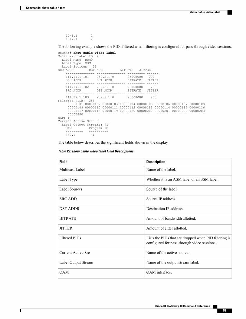
The following example shows the PIDs filtered when filtering is configured for pass-through video sessions:Router# show cable video labelMulticast Label ID: 2Label Name: ssm0Label Type: SSMLabel Sources: [3]
SRC ADDR DST ADDR BITRATE JITTER--------------- --------------- --------- ------111.17.1.101 232.2.1.0 25000000 200SRC ADDR DST ADDR BITRATE JITTER--------------- --------------- --------- ------111.17.1.102 232.2.1.0 25000000 200SRC ADDR DST ADDR BITRATE JITTER--------------- --------------- --------- ------111.17.1.103 232.2.1.0 25000000 200
Filtered PIDs: [25]00000101 00000102 00000103 00000104 00000105 00000106 00000107 0000010800000109 00000110 00000111 00000112 00000113 00000114 00000115 0000011600000117 00000118 00000119 00000120 00000200 00000201 00000202 0000020300000800
MAP: 1Current Active Src: 0Label Output Streams: [1]QAM Program ID--------- ----------3/7.1 -1
The table below describes the significant fields shown in the display.
Table 22: show cable video label Field Descriptions
DescriptionField
Name of the label.Multicast Label
Whether it is an ASM label or an SSM label.Label Type
Source of the label.Label Sources
Source IP address.SRC ADD
Destination IP address.DST ADDR
Amount of bandwidth allotted.BITRATE
Amount of Jitter allotted.JITTER
Lists the PIDs that are dropped when PID filtering isconfigured for pass-through video sessions.
Filtered PIDs
Name of the active source.Current Active Src
Name of the output stream label.Label Output Stream
QAM interface.QAM
Cisco RF Gateway 10 Command Reference 55
Commands: show cable h to vshow cable video label

DescriptionField
Program Identifier (PID).Program ID
Related Commands DescriptionCommand
Configures ASM video session definition.asm
Enters the cable video label configuration.cable video labels
Configures video multicast sessions on the QAMinterface.
cable video multicast
Configures SSM video session definition.ssm
Cisco RF Gateway 10 Command Reference56
Commands: show cable h to vshow cable video label
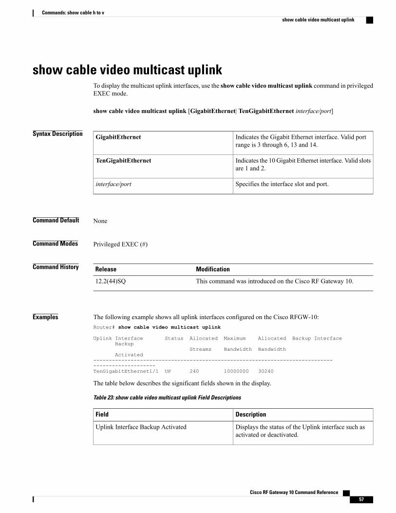
show cable video multicast uplinkTo display the multicast uplink interfaces, use the show cable video multicast uplink command in privilegedEXEC mode.
show cable video multicast uplink [GigabitEthernet| TenGigabitEthernet interface/port]
Syntax Description Indicates the Gigabit Ethernet interface. Valid portrange is 3 through 6, 13 and 14.
GigabitEthernet
Indicates the 10 Gigabit Ethernet interface. Valid slotsare 1 and 2.
TenGigabitEthernet
Specifies the interface slot and port.interface/port
Command Default None
Command Modes Privileged EXEC (#)
Command History ModificationRelease
This command was introduced on the Cisco RF Gateway 10.12.2(44)SQ
Examples The following example shows all uplink interfaces configured on the Cisco RFGW-10:Router# show cable video multicast uplink
Uplink Interface Status Allocated Maximum Allocated Backup InterfaceBackup
Streams Bandwidth BandwidthActivated
-------------------------------------------------------------------------------------------------TenGigabitEthernet1/1 UP 240 10000000 30240
The table below describes the significant fields shown in the display.
Table 23: show cable video multicast uplink Field Descriptions
DescriptionField
Displays the status of the Uplink interface such asactivated or deactivated.
Uplink Interface Backup Activated
Cisco RF Gateway 10 Command Reference 57
Commands: show cable h to vshow cable video multicast uplink

DescriptionField
Displays the status of the interface such as up ordown..
Status
Specifies the number of allotted streams.Allotted Streams
Specifies the maximum amount of bandwidth for thespecified interface
Maximum Bandwidth
Specifies the bandwidth allocated for that interface.Allocated Bandwidth
Dispays the name of the backup interface.Backup Interface
Related Commands DescriptionCommand
Configures an uplink port for multicast traffic.cable video multicast uplink
Enables multicast routing on the Cisco RFGW-10.ip multicast-routing
Cisco RF Gateway 10 Command Reference58
Commands: show cable h to vshow cable video multicast uplink
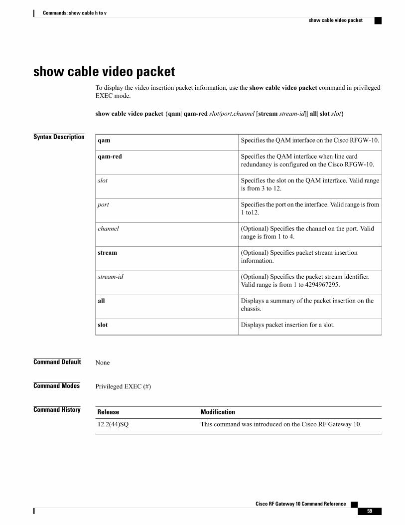
show cable video packetTo display the video insertion packet information, use the show cable video packet command in privilegedEXEC mode.
show cable video packet {qam| qam-red slot/port.channel [stream stream-id]| all| slot slot}
Syntax Description Specifies the QAM interface on the Cisco RFGW-10.qam
Specifies the QAM interface when line cardredundancy is configured on the Cisco RFGW-10.
qam-red
Specifies the slot on the QAM interface. Valid rangeis from 3 to 12.
slot
Specifies the port on the interface. Valid range is from1 to12.
port
(Optional) Specifies the channel on the port. Validrange is from 1 to 4.
channel
(Optional) Specifies packet stream insertioninformation.
stream
(Optional) Specifies the packet stream identifier.Valid range is from 1 to 4294967295.
stream-id
Displays a summary of the packet insertion on thechassis.
all
Displays packet insertion for a slot.slot
Command Default None
Command Modes Privileged EXEC (#)
Command History ModificationRelease
This command was introduced on the Cisco RF Gateway 10.12.2(44)SQ
Cisco RF Gateway 10 Command Reference 59
Commands: show cable h to vshow cable video packet
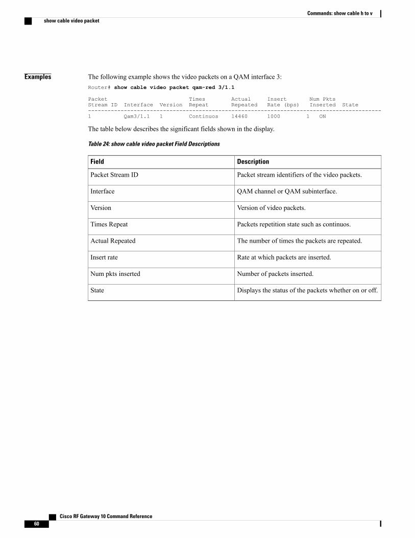
Examples The following example shows the video packets on a QAM interface 3:Router# show cable video packet qam-red 3/1.1
Packet Times Actual Insert Num PktsStream ID Interface Version Repeat Repeated Rate (bps) Inserted State------------------------------------------------------------------------------------------1 Qam3/1.1 1 Continuos 14460 1000 1 ON
The table below describes the significant fields shown in the display.
Table 24: show cable video packet Field Descriptions
DescriptionField
Packet stream identifiers of the video packets.Packet Stream ID
QAM channel or QAM subinterface.Interface
Version of video packets.Version
Packets repetition state such as continuos.Times Repeat
The number of times the packets are repeated.Actual Repeated
Rate at which packets are inserted.Insert rate
Number of packets inserted.Num pkts inserted
Displays the status of the packets whether on or off.State
Cisco RF Gateway 10 Command Reference60
Commands: show cable h to vshow cable video packet
show cable video routeTo display video route information, use the show cable video route command in privileged EXEC mode.
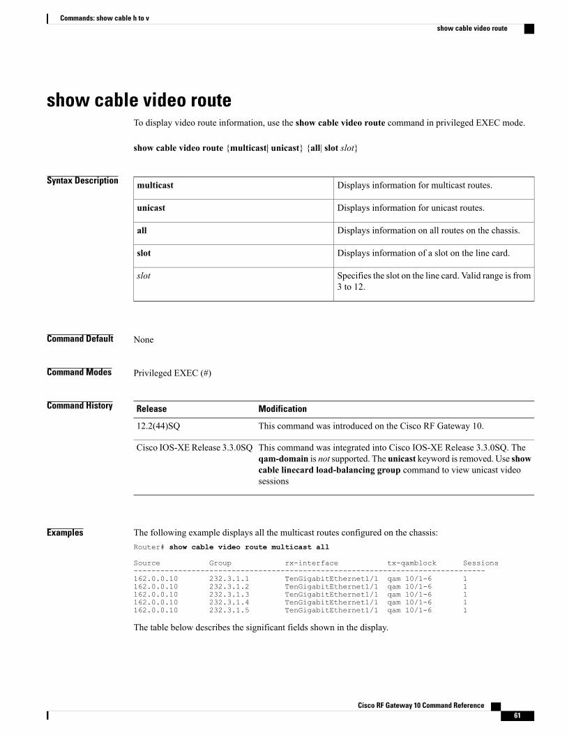
show cable video route {multicast| unicast} {all| slot slot}
Syntax Description Displays information for multicast routes.multicast
Displays information for unicast routes.unicast
Displays information on all routes on the chassis.all
Displays information of a slot on the line card.slot
Specifies the slot on the line card. Valid range is from3 to 12.
slot
Command Default None
Command Modes Privileged EXEC (#)
Command History ModificationRelease
This command was introduced on the Cisco RF Gateway 10.12.2(44)SQ
This command was integrated into Cisco IOS-XE Release 3.3.0SQ. Theqam-domain is not supported. The unicast keyword is removed. Use showcable linecard load-balancing group command to view unicast videosessions
Cisco IOS-XE Release 3.3.0SQ
Examples The following example displays all the multicast routes configured on the chassis:Router# show cable video route multicast all
Source Group rx-interface tx-qamblock Sessions-------------------------------------------------------------------------------162.0.0.10 232.3.1.1 TenGigabitEthernet1/1 qam 10/1-6 1162.0.0.10 232.3.1.2 TenGigabitEthernet1/1 qam 10/1-6 1162.0.0.10 232.3.1.3 TenGigabitEthernet1/1 qam 10/1-6 1162.0.0.10 232.3.1.4 TenGigabitEthernet1/1 qam 10/1-6 1162.0.0.10 232.3.1.5 TenGigabitEthernet1/1 qam 10/1-6 1
The table below describes the significant fields shown in the display.
Cisco RF Gateway 10 Command Reference 61
Commands: show cable h to vshow cable video route
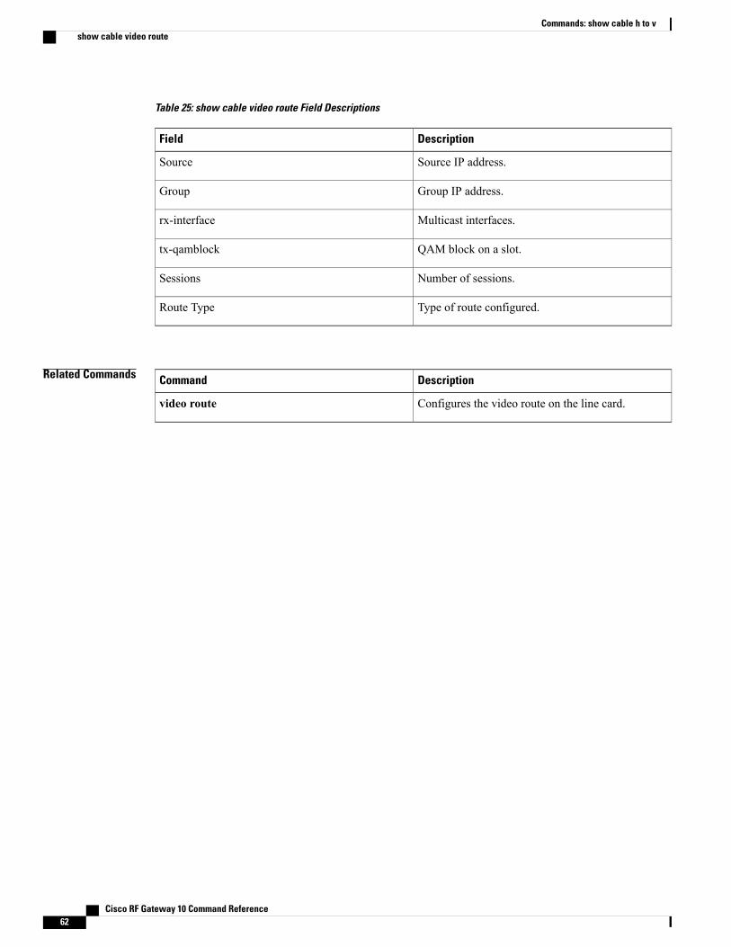
Table 25: show cable video route Field Descriptions
DescriptionField
Source IP address.Source
Group IP address.Group
Multicast interfaces.rx-interface
QAM block on a slot.tx-qamblock
Number of sessions.Sessions
Type of route configured.Route Type
Related Commands DescriptionCommand
Configures the video route on the line card.video route
Cisco RF Gateway 10 Command Reference62
Commands: show cable h to vshow cable video route
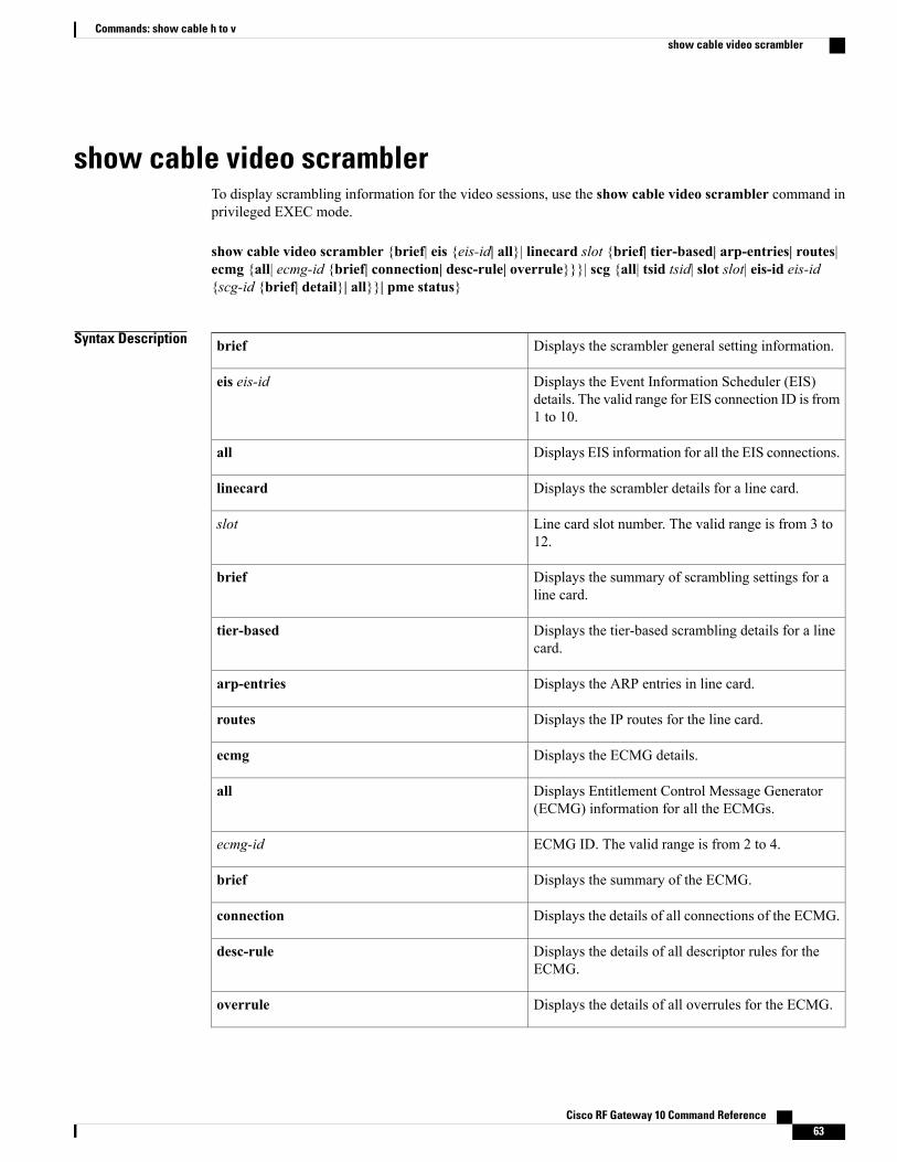
show cable video scramblerTo display scrambling information for the video sessions, use the show cable video scrambler command inprivileged EXEC mode.
show cable video scrambler {brief| eis {eis-id| all}| linecard slot {brief| tier-based| arp-entries| routes|ecmg {all| ecmg-id {brief| connection| desc-rule| overrule}}}| scg {all| tsid tsid| slot slot| eis-id eis-id{scg-id {brief| detail}| all}}| pme status}
Syntax Description Displays the scrambler general setting information.brief
Displays the Event Information Scheduler (EIS)details. The valid range for EIS connection ID is from1 to 10.
eis eis-id
Displays EIS information for all the EIS connections.all
Displays the scrambler details for a line card.linecard
Line card slot number. The valid range is from 3 to12.
slot
Displays the summary of scrambling settings for aline card.
brief
Displays the tier-based scrambling details for a linecard.
tier-based
Displays the ARP entries in line card.arp-entries
Displays the IP routes for the line card.routes
Displays the ECMG details.ecmg
Displays Entitlement Control Message Generator(ECMG) information for all the ECMGs.
all
ECMG ID. The valid range is from 2 to 4.ecmg-id
Displays the summary of the ECMG.brief
Displays the details of all connections of the ECMG.connection
Displays the details of all descriptor rules for theECMG.
desc-rule
Displays the details of all overrules for the ECMG.overrule
Cisco RF Gateway 10 Command Reference 63
Commands: show cable h to vshow cable video scrambler
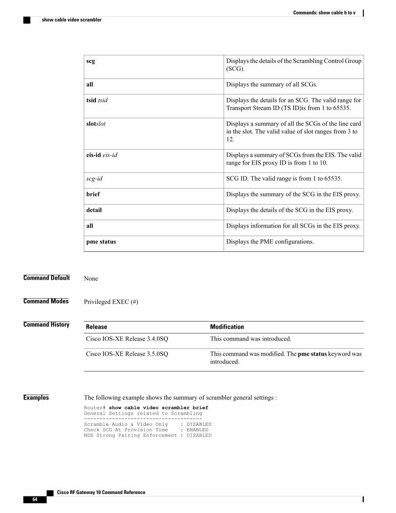
Displays the details of the Scrambling Control Group(SCG).
scg
Displays the summary of all SCGs.all
Displays the details for an SCG. The valid range forTransport Stream ID (TS ID)is from 1 to 65535.
tsid tsid
Displays a summary of all the SCGs of the line cardin the slot. The valid value of slot ranges from 3 to12.
slotslot
Displays a summary of SCGs from the EIS. The validrange for EIS proxy ID is from 1 to 10.
eis-id eis-id
SCG ID. The valid range is from 1 to 65535.scg-id
Displays the summary of the SCG in the EIS proxy.brief
Displays the details of the SCG in the EIS proxy.detail
Displays information for all SCGs in the EIS proxy.all
Displays the PME configurations.pme status
Command Default None
Command Modes Privileged EXEC (#)
Command History ModificationRelease
This command was introduced.Cisco IOS-XE Release 3.4.0SQ
This commandwasmodified. The pme status keyword wasintroduced.
Cisco IOS-XE Release 3.5.0SQ
Examples The following example shows the summary of scrambler general settings :Router# show cable video scrambler briefGeneral Settings related to Scrambling--------------------------------------Scramble Audio & Video Only : DISABLEDCheck SCG At Provision Time : ENABLEDNDS Strong Pairing Enforcement : DISABLED
Cisco RF Gateway 10 Command Reference64
Commands: show cable h to vshow cable video scrambler

The following example shows the EIS settings for all EIS connections:Router# show cable video scrambler eis all------------------------------------------------------------------------------------------EIS EIS Peer TCP CP CP Overwrite ConnectionID Name IP Port Overrule Duration SCG Status-------------------------------------------------------------------------------------------1 server1 0.0.0.0 1024 DISABLED 0 DISABLED Waiting10 test_EIS 0.0.0.0 6000 DISABLED 0 DISABLED Waiting------------------------------------------------------------------------------------------
NA - Not Available
The following example shows the EIS settings for EIS ID 1:Router# show cable video scrambler eis 1------------------------------------------------------------------------------------------EIS EIS Peer TCP CP CP Overwrite ConnectionID Name IP Port Overrule Duration SCG Status------------------------------------------------------------------------------------------1 server1 0.0.0.0 1024 DISABLED 0 DISABLED Waiting------------------------------------------------------------------------------------------
NA - Not Available
The following example shows the scrambler settings on line card 3:Router# show cable video scrambler linecard 3 briefCA Interface Details of Line Card : 3--------------------------------------IP Address : 192.168.2.250Net Mask : 255.255.255.0Gateway : 0.0.0.0--------------------------------------
Encryption Configuration Details of Line Card : 3--------------------------------------------------Encryption: DVBAlgorithm : DVB-CSA--------------------------------------------------
The following example shows the tier-based scrambling details on line card 3:Router# show cable video scrambler linecard 3 tier-based----------------------------------------------------------------SLOT TIER ECMG ID ACCESS CRITERIA----------------------------------------------------------------3 Enabled 2 A076B300005E----------------------------------------------------------------
The following example shows the ARP entries for line card 5:Router# show cable video scrambler linecard 3 arp-entries------------------------------------------SLOT IP ADDRESS MAC ADDRESS------------------------------------------192.168.0.8 30e4.db04.8dc0------------------------------------------
The following example shows the IP routes for line card 3:Router# show cable video scrambler linecard 3 routes-----------------------------------------------------------SLOT IP ADDRESS GATEWAY SUBNET MASK-----------------------------------------------------------3 192.168.0.15 192.168.0.19 255.255.255.128-----------------------------------------------------------
The following example shows the ECMG information for all ECMGs on line card 3:Router# show cable video scrambler linecard 3 ecmg all-----------------------------------------------------------------------------------------------------------------------ECMG ECMG ECMG CA Sys CA Subsys PID Lower Upper Streams/ Open Streams/
Cisco RF Gateway 10 Command Reference 65
Commands: show cable h to vshow cable video scrambler
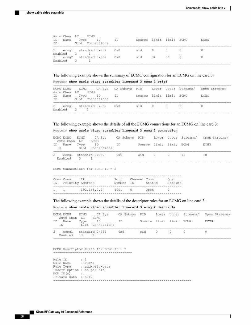
Auto Chan LC ECMGID Name Type ID ID Source limit limit ECMG ECMGID Slot Connections-----------------------------------------------------------------------------------------------------------------------2 ecmg1 standard 0x952 0x0 sid 0 0 0 0Enabled 3 13 ecmg2 standard 0x952 0x0 sid 34 36 0 0Enabled 3 1-----------------------------------------------------------------------------------------------------------------------
The following example shows the summary of ECMG configuration for an ECMG on line card 3:Router# show cable video scrambler linecard 3 ecmg 2 brief-----------------------------------------------------------------------------------------------------------------------ECMG ECMG ECMG CA Sys CA Subsys PID Lower Upper Streams/ Open Streams/Auto Chan LC ECMGID Name Type ID ID Source limit limit ECMG ECMGID Slot Connections-----------------------------------------------------------------------------------------------------------------------2 ecmg1 standard 0x952 0x0 sid 0 0 0 0Enabled 3 1-----------------------------------------------------------------------------------------------------------------------
The following example shows the details of all the ECMG connections for an ECMG on line card 3:Router# show cable video scrambler linecard 3 ecmg 2 connection------------------------------------------------------------------------------------------------------------------------ECMG ECMG ECMG CA Sys CA Subsys PID Lower Upper Streams/ Open Streams/Auto Chan LC ECMG
ID Name Type ID ID Source limit limit ECMG ECMGID Slot Connections
------------------------------------------------------------------------------------------------------------------------2 ecmg1 standard 0x952 0x0 sid 0 0 18 18Enabled 3 1
------------------------------------------------------------------------------------------------------------------------
ECMG Connections for ECMG ID = 2
-----------------------------------------------------------------Conn Conn IP Port Channel Conn OpenID Priority Address Number ID Status Streams-----------------------------------------------------------------1 1 192.168.0.2 4001 0 Open 0-----------------------------------------------------------------
The following example shows the details of the descriptor rules for an ECMG on line card 3:Router# show cable video scrambler linecard 3 ecmg 2 desc-rule--------------------------------------------------------------------------------------------------------------------------ECMG ECMG ECMG CA Sys CA Subsys PID Lower Upper Streams/ Open Streams/
Auto Chan LC ECMGID Name Type ID ID Source limit limit ECMG ECMG
ID Slot Connections--------------------------------------------------------------------------------------------------------------------------2 ecmg1 standard 0x952 0x0 sid 0 0 0 0
Enabled 3 1--------------------------------------------------------------------------------------------------------------------------
ECMG Descriptor Rules for ECMG ID = 2----------------------------------------
Rule ID : 1Rule Name : rule1Rule Type : add-priv-dataInsert Option : as-per-eisECM ID(s) :Private Data : a042----------------------------------------------------------------------
Cisco RF Gateway 10 Command Reference66
Commands: show cable h to vshow cable video scrambler
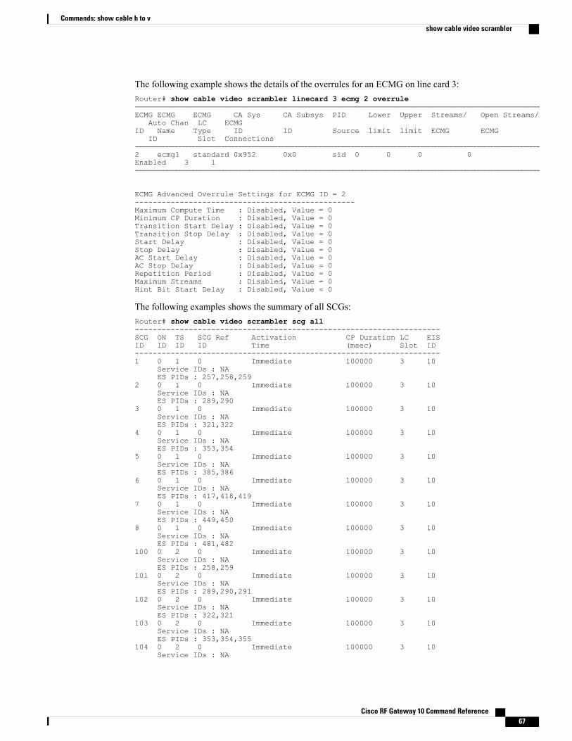
The following example shows the details of the overrules for an ECMG on line card 3:Router# show cable video scrambler linecard 3 ecmg 2 overrule--------------------------------------------------------------------------------------------------------------------------ECMG ECMG ECMG CA Sys CA Subsys PID Lower Upper Streams/ Open Streams/
Auto Chan LC ECMGID Name Type ID ID Source limit limit ECMG ECMG
ID Slot Connections--------------------------------------------------------------------------------------------------------------------------2 ecmg1 standard 0x952 0x0 sid 0 0 0 0Enabled 3 1--------------------------------------------------------------------------------------------------------------------------
ECMG Advanced Overrule Settings for ECMG ID = 2-------------------------------------------------Maximum Compute Time : Disabled, Value = 0Minimum CP Duration : Disabled, Value = 0Transition Start Delay : Disabled, Value = 0Transition Stop Delay : Disabled, Value = 0Start Delay : Disabled, Value = 0Stop Delay : Disabled, Value = 0AC Start Delay : Disabled, Value = 0AC Stop Delay : Disabled, Value = 0Repetition Period : Disabled, Value = 0Maximum Streams : Disabled, Value = 0Hint Bit Start Delay : Disabled, Value = 0
The following examples shows the summary of all SCGs:Router# show cable video scrambler scg all--------------------------------------------------------------------SCG ON TS SCG Ref Activation CP Duration LC EISID ID ID ID Time (msec) Slot ID--------------------------------------------------------------------1 0 1 0 Immediate 100000 3 10
Service IDs : NAES PIDs : 257,258,259
2 0 1 0 Immediate 100000 3 10Service IDs : NAES PIDs : 289,290
3 0 1 0 Immediate 100000 3 10Service IDs : NAES PIDs : 321,322
4 0 1 0 Immediate 100000 3 10Service IDs : NAES PIDs : 353,354
5 0 1 0 Immediate 100000 3 10Service IDs : NAES PIDs : 385,386
6 0 1 0 Immediate 100000 3 10Service IDs : NAES PIDs : 417,418,419
7 0 1 0 Immediate 100000 3 10Service IDs : NAES PIDs : 449,450
8 0 1 0 Immediate 100000 3 10Service IDs : NAES PIDs : 481,482
100 0 2 0 Immediate 100000 3 10Service IDs : NAES PIDs : 258,259
101 0 2 0 Immediate 100000 3 10Service IDs : NAES PIDs : 289,290,291
102 0 2 0 Immediate 100000 3 10Service IDs : NAES PIDs : 322,321
103 0 2 0 Immediate 100000 3 10Service IDs : NAES PIDs : 353,354,355
104 0 2 0 Immediate 100000 3 10Service IDs : NA
Cisco RF Gateway 10 Command Reference 67
Commands: show cable h to vshow cable video scrambler
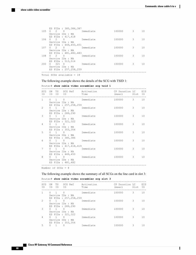
ES PIDs : 385,386,387105 0 2 0 Immediate 100000 3 10
Service IDs : NAES PIDs : 417,418
106 0 2 0 Immediate 100000 3 10Service IDs : NAES PIDs : 449,450,451
107 0 2 0 Immediate 100000 3 10Service IDs : NAES PIDs : 481,482,483
108 0 2 0 Immediate 100000 3 10Service IDs : NAES PIDs : 513,514
200 0 321 0 Immediate 100000 3 10Service IDs : NAES PIDs : 257,258,259
--------------------------------------------------------------------Total SCGs available = 18
The following example shows the details of the SCG with TSID 1:Router# show cable video scrambler scg tsid 1--------------------------------------------------------------------SCG ON TS SCG Ref Activation CP Duration LC EISID ID ID ID Time (msec) Slot ID--------------------------------------------------------------------1 0 1 0 Immediate 100000 3 10
Service IDs : NAES PIDs : 257,258,259
2 0 1 0 Immediate 100000 3 10Service IDs : NAES PIDs : 289,290
3 0 1 0 Immediate 100000 3 10Service IDs : NAES PIDs : 321,322
4 0 1 0 Immediate 100000 3 10Service IDs : NAES PIDs : 353,354
5 0 1 0 Immediate 100000 3 10Service IDs : NAES PIDs : 385,386
6 0 1 0 Immediate 100000 3 10Service IDs : NAES PIDs : 417,418,419
7 0 1 0 Immediate 100000 3 10Service IDs : NAES PIDs : 449,450
8 0 1 0 Immediate 100000 3 10Service IDs : NAES PIDs : 481,482
--------------------------------------------------------------------Number of SCGs = 8
The following example shows the summary of all SCGs on the line card in slot 3:Router# show cable video scrambler scg slot 3--------------------------------------------------------------------SCG ON TS SCG Ref Activation CP Duration LC EISID ID ID ID Time (msec) Slot ID--------------------------------------------------------------------1 0 1 0 Immediate 100000 3 10
Service IDs : NAES PIDs : 257,258,259
2 0 1 0 Immediate 100000 3 10Service IDs : NAES PIDs : 289,290
3 0 1 0 Immediate 100000 3 10Service IDs : NAES PIDs : 321,322
4 0 1 0 Immediate 100000 3 10Service IDs : NAES PIDs : 353,354
5 0 1 0 Immediate 100000 3 10
Cisco RF Gateway 10 Command Reference68
Commands: show cable h to vshow cable video scrambler
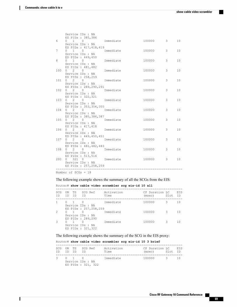
Service IDs : NAES PIDs : 385,386
6 0 1 0 Immediate 100000 3 10Service IDs : NAES PIDs : 417,418,419
7 0 1 0 Immediate 100000 3 10Service IDs : NAES PIDs : 449,450
8 0 1 0 Immediate 100000 3 10Service IDs : NAES PIDs : 481,482
100 0 2 0 Immediate 100000 3 10Service IDs : NAES PIDs : 258,259
101 0 2 0 Immediate 100000 3 10Service IDs : NAES PIDs : 289,290,291
102 0 2 0 Immediate 100000 3 10Service IDs : NAES PIDs : 322,321
103 0 2 0 Immediate 100000 3 10Service IDs : NAES PIDs : 353,354,355
104 0 2 0 Immediate 100000 3 10Service IDs : NAES PIDs : 385,386,387
105 0 2 0 Immediate 100000 3 10Service IDs : NAES PIDs : 417,418
106 0 2 0 Immediate 100000 3 10Service IDs : NAES PIDs : 449,450,451
107 0 2 0 Immediate 100000 3 10Service IDs : NAES PIDs : 481,482,483
108 0 2 0 Immediate 100000 3 10Service IDs : NAES PIDs : 513,514
200 0 321 0 Immediate 100000 3 10Service IDs : NAES PIDs : 257,258,259
--------------------------------------------------------------------Number of SCGs = 18
The following example shows the summary of all the SCGs from the EIS:Router# show cable video scrambler scg eis-id 10 all--------------------------------------------------------------------SCG ON TS SCG Ref Activation CP Duration LC EISID ID ID ID Time (msec) Slot ID--------------------------------------------------------------------1 0 1 0 Immediate 100000 3 10
Service IDs : NAES PIDs : 257,258,259
2 0 1 0 Immediate 100000 3 10Service IDs : NAES PIDs : 289,290
3 0 1 0 Immediate 100000 3 10Service IDs : NAES PIDs : 321,322
The following example shows the summary of the SCG in the EIS proxy:Router# show cable video scrambler scg eis-id 10 3 brief--------------------------------------------------------------------SCG ON TS SCG Ref Activation CP Duration LC EISID ID ID ID Time (msec) Slot ID--------------------------------------------------------------------3 0 1 0 Immediate 100000 3 10
Service IDs : NAES PIDs : 321, 322
Cisco RF Gateway 10 Command Reference 69
Commands: show cable h to vshow cable video scrambler
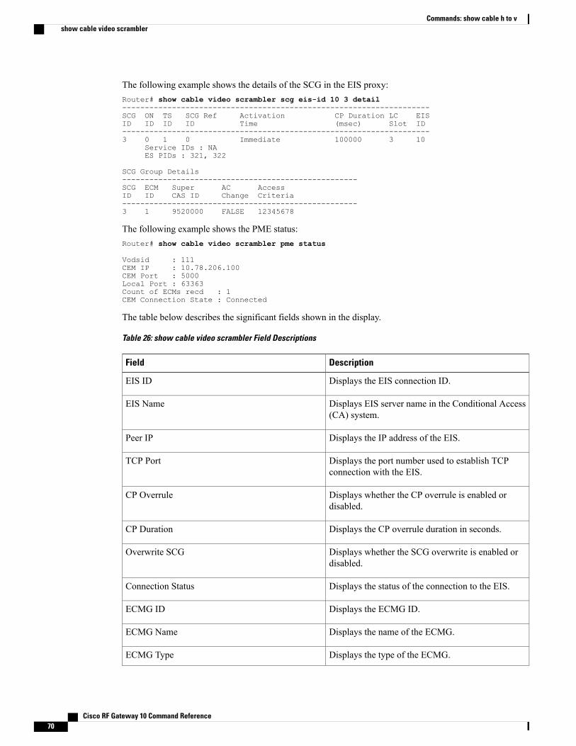
The following example shows the details of the SCG in the EIS proxy:Router# show cable video scrambler scg eis-id 10 3 detail--------------------------------------------------------------------SCG ON TS SCG Ref Activation CP Duration LC EISID ID ID ID Time (msec) Slot ID--------------------------------------------------------------------3 0 1 0 Immediate 100000 3 10
Service IDs : NAES PIDs : 321, 322
SCG Group Details----------------------------------------------------SCG ECM Super AC AccessID ID CAS ID Change Criteria----------------------------------------------------3 1 9520000 FALSE 12345678
The following example shows the PME status:Router# show cable video scrambler pme status
Vodsid : 111CEM IP : 10.78.206.100CEM Port : 5000Local Port : 63363Count of ECMs recd : 1CEM Connection State : Connected
The table below describes the significant fields shown in the display.
Table 26: show cable video scrambler Field Descriptions
DescriptionField
Displays the EIS connection ID.EIS ID
Displays EIS server name in the Conditional Access(CA) system.
EIS Name
Displays the IP address of the EIS.Peer IP
Displays the port number used to establish TCPconnection with the EIS.
TCP Port
Displays whether the CP overrule is enabled ordisabled.
CP Overrule
Displays the CP overrule duration in seconds.CP Duration
Displays whether the SCG overwrite is enabled ordisabled.
Overwrite SCG
Displays the status of the connection to the EIS.Connection Status
Displays the ECMG ID.ECMG ID
Displays the name of the ECMG.ECMG Name
Displays the type of the ECMG.ECMG Type
Cisco RF Gateway 10 Command Reference70
Commands: show cable h to vshow cable video scrambler
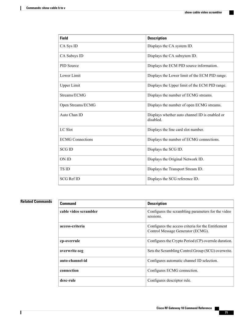
DescriptionField
Displays the CA system ID.CA Sys ID
Displays the CA subsytem ID.CA Subsys ID
Displays the ECM PID source information.PID Source
Displays the Lower limit of the ECM PID range.Lower Limit
Displays the Upper limit of the ECM PID range.Upper Limit
Displays the number of ECMG streams.Streams/ECMG
Displays the number of open ECMG streams.Open Streams/ECMG
Displays whether auto channel ID is enabled ordisabled.
Auto Chan ID
Displays the line card slot number.LC Slot
Displays the number of ECMG connections.ECMG Connections
Displays the SCG ID.SCG ID
Displays the Original Network ID.ON ID
Displays the Transport Stream ID.TS ID
Displays the SCG reference ID.SCG Ref ID
Related Commands DescriptionCommand
Configures the scrambling parameters for the videosessions.
cable video scrambler
Configures the access criteria for the EntitlementControl Message Generator (ECMG).
access-criteria
Configures the Crypto Period (CP) overrule duration.cp-overrule
Sets the Scrambling Control Group (SCG) overwrite.overwrite-scg
Configures automatic channel ID selection.auto-channel-id
Configures ECMG connection.connection
Configures descriptor rule.desc-rule
Cisco RF Gateway 10 Command Reference 71
Commands: show cable h to vshow cable video scrambler

DescriptionCommand
Overrules the default setting for the ECMG.overrule
Cisco RF Gateway 10 Command Reference72
Commands: show cable h to vshow cable video scrambler
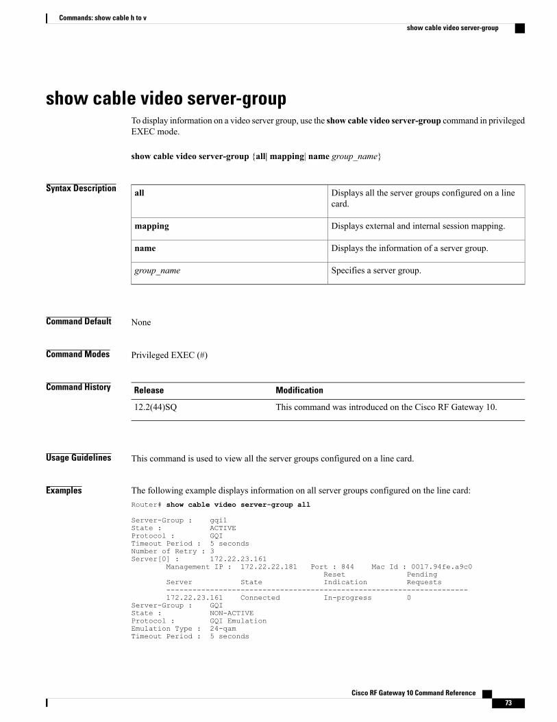
show cable video server-groupTo display information on a video server group, use the show cable video server-group command in privilegedEXEC mode.
show cable video server-group {all| mapping| name group_name}
Syntax Description Displays all the server groups configured on a linecard.
all
Displays external and internal session mapping.mapping
Displays the information of a server group.name
Specifies a server group.group_name
Command Default None
Command Modes Privileged EXEC (#)
Command History ModificationRelease
This command was introduced on the Cisco RF Gateway 10.12.2(44)SQ
Usage Guidelines This command is used to view all the server groups configured on a line card.
Examples The following example displays information on all server groups configured on the line card:Router# show cable video server-group all
Server-Group : gqi1State : ACTIVEProtocol : GQITimeout Period : 5 secondsNumber of Retry : 3Server[0] : 172.22.23.161
Management IP : 172.22.22.181 Port : 844 Mac Id : 0017.94fe.a9c0Reset Pending
Server State Indication Requests---------------------------------------------------------------------172.22.23.161 Connected In-progress 0
Server-Group : GQIState : NON-ACTIVEProtocol : GQI EmulationEmulation Type : 24-qamTimeout Period : 5 seconds
Cisco RF Gateway 10 Command Reference 73
Commands: show cable h to vshow cable video server-group
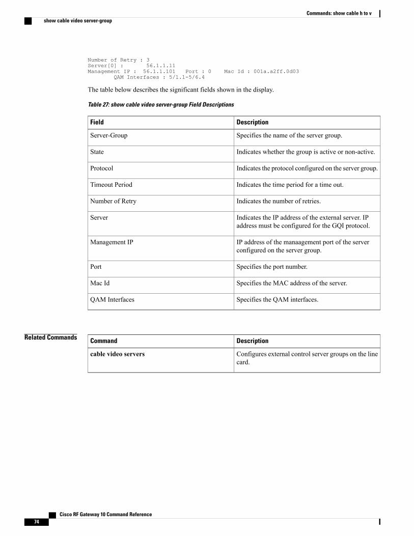
Number of Retry : 3Server[0] : 56.1.1.11Management IP : 56.1.1.101 Port : 0 Mac Id : 001a.a2ff.0d03
QAM Interfaces : 5/1.1-5/6.4
The table below describes the significant fields shown in the display.
Table 27: show cable video server-group Field Descriptions
DescriptionField
Specifies the name of the server group.Server-Group
Indicates whether the group is active or non-active.State
Indicates the protocol configured on the server group.Protocol
Indicates the time period for a time out.Timeout Period
Indicates the number of retries.Number of Retry
Indicates the IP address of the external server. IPaddress must be configured for the GQI protocol.
Server
IP address of the manaagement port of the serverconfigured on the server group.
Management IP
Specifies the port number.Port
Specifies the MAC address of the server.Mac Id
Specifies the QAM interfaces.QAM Interfaces
Related Commands DescriptionCommand
Configures external control server groups on the linecard.
cable video servers
Cisco RF Gateway 10 Command Reference74
Commands: show cable h to vshow cable video server-group
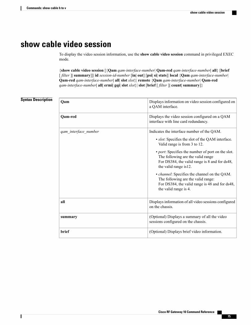
show cable video sessionTo display the video session information, use the show cable video session command in privileged EXECmode.
{show cable video session [{Qam qam-interface-number| Qam-red qam-interface-number| all} [brief[ filter ]| summary]]| id session-id-number [in| out] [psi| si| stats]| local {Qam qam-interface-number|Qam-red qam-interface-number| all| slot slot}| remote {Qam qam-interface-number| Qam-redqam-interface-number| all| ermi| gqi| slot slot}| slot [brief [ filter ]| count| summary]}
Syntax Description Displays information on video session configured ona QAM interface.
Qam
Displays the video session configured on a QAMinterface with line card redundancy.
Qam-red
Indicates the interface number of the QAM.
• slot: Specifies the slot of the QAM interface.Valid range is from 3 to 12.
• port: Specifies the number of port on the slot.The following are the valid rangeFor DS384, the valid range is 8 and for ds48,the valid range is12.
• channel: Specifies the channel on the QAM.The following are the valid range:For DS384, the valid range is 48 and for ds48,the valid range is 4.
qam_interface_number
Displays information of all video sessions configuredon the chassis.
all
(Optional) Displays a summary of all the videosessions configured on the chassis.
summary
(Optional) Displays brief video information.brief
Cisco RF Gateway 10 Command Reference 75
Commands: show cable h to vshow cable video session

(Optional) Filters the information using the followingcriteria:
• active—Shows the active sessions present.
• asm—Shows the ASM video sessions.
• blocked—Shows blocked video sessions.
• data—Shows sessions with the data-pipingprocessing type.
• idle—Shows idle sessions.
• off—Shows off sessions.
• passthru—Shows sessions with thepass-through processing type.
• psi—Shows packet stream identifiers of videosessions.
• remap—Shows remapped video streams.
• shell—shows video sessions in shell.
• ssm—Shows SSM video sessions.
• udp—Shows the UDP port.
filter
Displays video session information for a session ID.id
Specifies the ID of a particular session. Valid sessionIDs are 1 and 2.
session-id-number
(Optional) Displays input session information.in
(Optional) Displays output session information.out
(Optional) Displays only the SI information of aninput or output session.
si
(Optional) Displays detailed Program SpecificInformation (PSI) video session information withprogram table.
psi
(Optional) Displays detailed video session
.
stats
Displays video sessions information for a slot.slot
Specifies the slot on the QAM interface. Valid slotnumber range is from 3 to 12.
slot
Cisco RF Gateway 10 Command Reference76
Commands: show cable h to vshow cable video session

Displays video session information for ERMIsessions.
ermi
Displays video session information for GQI sessions.gqi
(Optional) Displays the session count for all QAMchannels on the line card interface.
count
Displays local video sessions.local
Displays remote video sessions.remote
Command Default None
Command Modes Privileged EXEC (#)
Command History ModificationRelease
This command was introduced on the Cisco RF Gateway 10.12.2(44)SQ
This command was modified. The count keyword was added.12.2(50)SQ2
This command was integrated into Cisco IOS-XE Release 3.3.0SQ.qam-domain is not supported. The local and remote keywords areadded.
Cisco IOS-XE Release 3.3.0SQ
This command was modified. The si keyword was added. Thecommand displays the de-jittering mode and master PCR information.
Cisco IOS-XE Release 3.4.0SQ
This commandwasmodified. A new columnCurrent Statewas addedin the command output.
Cisco IOS-XE Release 3.5.0SQ
Examples The following example shows the video sessions configured on 3/1.1 QAM interface:Router# show cable video session qam 3/1.1
Session QAM Stream Sess IP UDP Out Input Input Output PSIID Port Type Type Address Port Pgm Bitrate State State Rdy
Ctrl Encryption CurrentState Type State--------- ---------- ------- ---- --------- ----- --- ------- ------ ------ ---201392133 3/1.1 Remap UDP 30.0.3.10 49155 4 2999750 ACTIVE ON YES- DVB Encrypted201392134 3/1.1 Remap UDP 30.0.3.10 49156 5 2999856 ACTIVE ON YES- DVB Encrypted201392135 3/1.1 Remap UDP 30.0.3.10 49157 6 2993065 ACTIVE ON YES- DVB EncryptedTotal Sessions = 3
Cisco RF Gateway 10 Command Reference 77
Commands: show cable h to vshow cable video session
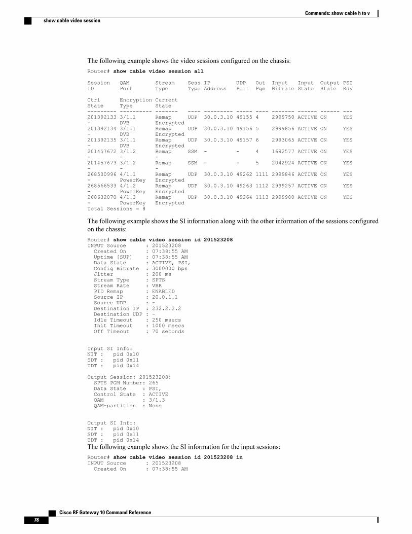
The following example shows the video sessions configured on the chassis:Router# show cable video session all
Session QAM Stream Sess IP UDP Out Input Input Output PSIID Port Type Type Address Port Pgm Bitrate State State Rdy
Ctrl Encryption CurrentState Type State--------- ---------- ------- ---- --------- ----- ---- ------- ------ ------ ---201392133 3/1.1 Remap UDP 30.0.3.10 49155 4 2999750 ACTIVE ON YES- DVB Encrypted201392134 3/1.1 Remap UDP 30.0.3.10 49156 5 2999856 ACTIVE ON YES- DVB Encrypted201392135 3/1.1 Remap UDP 30.0.3.10 49157 6 2993065 ACTIVE ON YES- DVB Encrypted201457672 3/1.2 Remap SSM - - 4 1692577 ACTIVE ON YES- - -201457673 3/1.2 Remap SSM - - 5 2042924 ACTIVE ON YES- - -268500996 4/1.1 Remap UDP 30.0.3.10 49262 1111 2999846 ACTIVE ON YES- PowerKey Encrypted268566533 4/1.2 Remap UDP 30.0.3.10 49263 1112 2999257 ACTIVE ON YES- PowerKey Encrypted268632070 4/1.3 Remap UDP 30.0.3.10 49264 1113 2999980 ACTIVE ON YES- PowerKey EncryptedTotal Sessions = 8
The following example shows the SI information along with the other information of the sessions configuredon the chassis:Router# show cable video session id 201523208INPUT Source : 201523208Created On : 07:38:55 AMUptime [SUP] : 07:38:55 AMData State : ACTIVE, PSI,Config Bitrate : 3000000 bpsJitter : 200 msStream Type : SPTSStream Rate : VBRPID Remap : ENABLEDSource IP : 20.0.1.1Source UDP : -Destination IP : 232.2.2.2Destination UDP : -Idle Timeout : 250 msecsInit Timeout : 1000 msecsOff Timeout : 70 seconds
Input SI Info:NIT : pid 0x10SDT : pid 0x11TDT : pid 0x14
Output Session: 201523208:SPTS PGM Number: 265Data State : PSI,Control State : ACTIVEQAM : 3/1.3QAM-partition : None
Output SI Info:NIT : pid 0x10SDT : pid 0x11TDT : pid 0x14The following example shows the SI information for the input sessions:Router# show cable video session id 201523208 inINPUT Source : 201523208Created On : 07:38:55 AM
Cisco RF Gateway 10 Command Reference78
Commands: show cable h to vshow cable video session
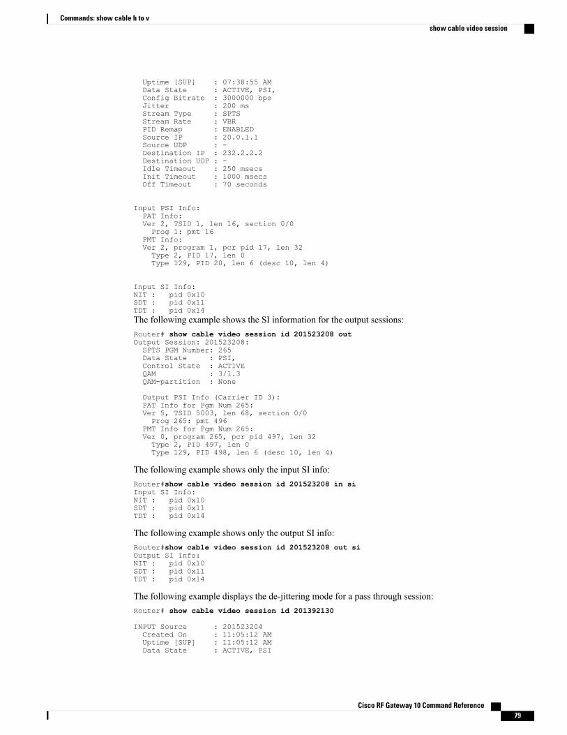
Uptime [SUP] : 07:38:55 AMData State : ACTIVE, PSI,Config Bitrate : 3000000 bpsJitter : 200 msStream Type : SPTSStream Rate : VBRPID Remap : ENABLEDSource IP : 20.0.1.1Source UDP : -Destination IP : 232.2.2.2Destination UDP : -Idle Timeout : 250 msecsInit Timeout : 1000 msecsOff Timeout : 70 seconds
Input PSI Info:PAT Info:Ver 2, TSID 1, len 16, section 0/0Prog 1: pmt 16
PMT Info:Ver 2, program 1, pcr pid 17, len 32Type 2, PID 17, len 0Type 129, PID 20, len 6 (desc 10, len 4)
Input SI Info:NIT : pid 0x10SDT : pid 0x11TDT : pid 0x14The following example shows the SI information for the output sessions:Router# show cable video session id 201523208 outOutput Session: 201523208:SPTS PGM Number: 265Data State : PSI,Control State : ACTIVEQAM : 3/1.3QAM-partition : None
Output PSI Info (Carrier ID 3):PAT Info for Pgm Num 265:Ver 5, TSID 5003, len 68, section 0/0Prog 265: pmt 496
PMT Info for Pgm Num 265:Ver 0, program 265, pcr pid 497, len 32Type 2, PID 497, len 0Type 129, PID 498, len 6 (desc 10, len 4)
The following example shows only the input SI info:Router#show cable video session id 201523208 in siInput SI Info:NIT : pid 0x10SDT : pid 0x11TDT : pid 0x14
The following example shows only the output SI info:Router#show cable video session id 201523208 out siOutput SI Info:NIT : pid 0x10SDT : pid 0x11TDT : pid 0x14
The following example displays the de-jittering mode for a pass through session:Router# show cable video session id 201392130
INPUT Source : 201523204Created On : 11:05:12 AMUptime [SUP] : 11:05:12 AMData State : ACTIVE, PSI
Cisco RF Gateway 10 Command Reference 79
Commands: show cable h to vshow cable video session
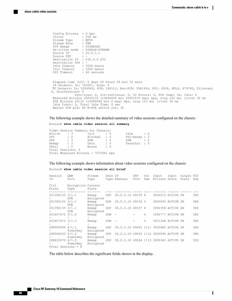
Config Bitrate : 0 bpsJitter : 200 msStream Type : MPTSStream Rate : VBRPID Remap : DISABLEDDe-jitter mode : SINGLE-STREAMSource IP : 20.0.1.1Source UDP : -Destination IP : 232.2.2.253Destination UDP : -Idle Timeout : 5000 msecsInit Timeout : 1000 msecsOff Timeout : 60 seconds
Elapsed time [LC]: 0 days 00 hours 06 min 33 secsIP Packets: In: 743567, Drop: 0TP Packets: In: 5204969, PCR: 180513, Non-PCR: 3981494, PSI: 4939, NULL: 679782, Filtered:0, Unreferenced: 0
Sync-Loss: 0, Dis-continous: 0, CC Errors: 0, PCR Jump: 34, Idle: 0Measured Bitrate 20000155 (19994056 min 20003570 max) bps, stay 163 ms, jitter 30 msPCR Bitrate 20132 (19994084 min 0 max) bps, stay 163 ms, jitter 30 msIdle Count: 0, Total Idle Time: 0 secMaster PCR pid: 80 M-PCR switch cnt: 35
The following example shows the detailed summary of video sessions configured on the chassis:Router# show cable video session all summary
Video Session Summary for Chassis:Active : 3 Init : 0 Idle : 0Off : 0 Blocked : 0 PSI-Ready : 3UDP : 3 ASM : 0 SSM : 0Remap : 3 Data : 0 Passthru : 0Shell : 0 Bound : 0Total Sessions: 3Total Measured Bitrate : 7070361 bps
The following example shows information about video sessions configured on the chassis:Router# show cable video session all brief
Session QAM Stream Sess IP UDP Out Input Input Output PSIID Port Type Type Address Port Pgm Bitrate State State Rdy
Ctrl Encryption CurrentState Type State--------- ---------- ------- ---- --------- ----- ---- ------- ------ ------ ---201392133 3/1.1 Remap UDP 30.0.3.10 49155 4 3000215 ACTIVE ON YES- DVB Encrypted201392134 3/1.1 Remap UDP 30.0.3.10 49156 5 3000093 ACTIVE ON YES- DVB Encrypted201392135 3/1.1 Remap UDP 30.0.3.10 49157 6 2992358 ACTIVE ON YES- DVB Encrypted201457672 3/1.2 Remap SSM - - 4 1692777 ACTIVE ON YES- - -201457673 3/1.2 Remap SSM - - 5 2051344 ACTIVE ON YES- - -268500996 4/1.1 Remap UDP 30.0.3.10 49262 1111 3000480 ACTIVE ON YES- PowerKey Encrypted268566533 4/1.2 Remap UDP 30.0.3.10 49263 1112 3000094 ACTIVE ON YES- PowerKey Encrypted268632070 4/1.3 Remap UDP 30.0.3.10 49264 1113 3000342 ACTIVE ON YES- PowerKey EncryptedTotal Sessions = 8
The table below describes the significant fields shown in the display.
Cisco RF Gateway 10 Command Reference80
Commands: show cable h to vshow cable video session

Table 28: show cable video session all Field Descriptions
DescriptionField
Represents the internal ID allocated by the chassis tothe output stream of the input session.
Session ID
Indicates the QAM interface or QAM subinterface.QAM Port
Indicates the transport stream.Stream Type
Session IP addressIP address
Indicates the video session type.Session Type
Indicates the UDP port.UDP Port
Indicates the Single ProgramTransport Stream (SPTS)or Multiple ProgramTransport Stream (MPTS)program number.
Output Program
Indicates the actual bitrate measured on the input.Input Bitrate
Indicates the state on the input.Input State
Indicates the stare on the output.Output State
Indicates the PSI ready state.PSI Rdy
Indicates the controller state.Ctrl State
Indicates the encryption type.Encryption Type
Indicates the encryption state.Current State
The following example shows the detailed video session configuration on the line card:Router# show cable video session id 201392130
INPUT Source : 201392130Created On : 04:41:10 AMUptime [SUP] : 04:41:10 AMData State : ACTIVE, PSI,Config Bitrate : 3000000 bpsJitter : 200 msStream Type : SPTSStream Rate : VBRPID Remap : ENABLEDSource IP : 0.0.0.0Source UDP : 0Destination IP : 30.0.3.10Destination UDP : 49261Idle Timeout : 250 msecsInit Timeout : 1000 msecsOff Timeout : 60 secondsPID Filter [0] :
Cisco RF Gateway 10 Command Reference 81
Commands: show cable h to vshow cable video session
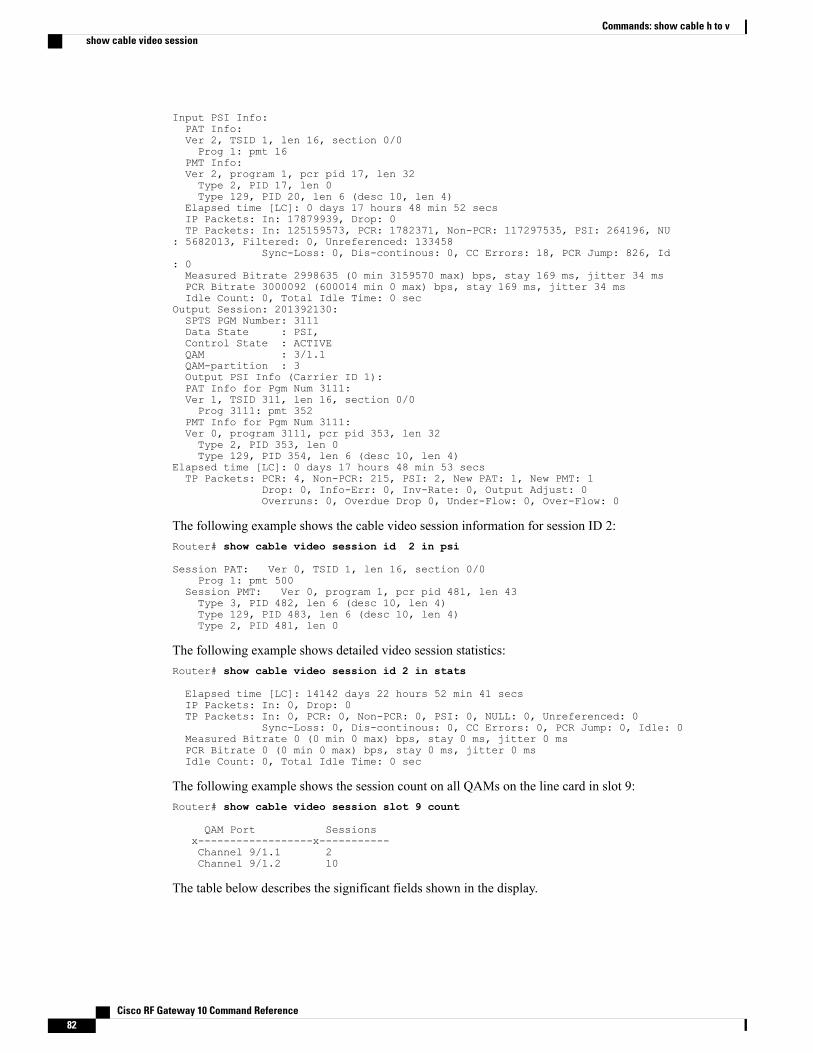
Input PSI Info:PAT Info:Ver 2, TSID 1, len 16, section 0/0Prog 1: pmt 16
PMT Info:Ver 2, program 1, pcr pid 17, len 32Type 2, PID 17, len 0Type 129, PID 20, len 6 (desc 10, len 4)
Elapsed time [LC]: 0 days 17 hours 48 min 52 secsIP Packets: In: 17879939, Drop: 0TP Packets: In: 125159573, PCR: 1782371, Non-PCR: 117297535, PSI: 264196, NU
: 5682013, Filtered: 0, Unreferenced: 133458Sync-Loss: 0, Dis-continous: 0, CC Errors: 18, PCR Jump: 826, Id
: 0Measured Bitrate 2998635 (0 min 3159570 max) bps, stay 169 ms, jitter 34 msPCR Bitrate 3000092 (600014 min 0 max) bps, stay 169 ms, jitter 34 msIdle Count: 0, Total Idle Time: 0 sec
Output Session: 201392130:SPTS PGM Number: 3111Data State : PSI,Control State : ACTIVEQAM : 3/1.1QAM-partition : 3Output PSI Info (Carrier ID 1):PAT Info for Pgm Num 3111:Ver 1, TSID 311, len 16, section 0/0Prog 3111: pmt 352
PMT Info for Pgm Num 3111:Ver 0, program 3111, pcr pid 353, len 32Type 2, PID 353, len 0Type 129, PID 354, len 6 (desc 10, len 4)
Elapsed time [LC]: 0 days 17 hours 48 min 53 secsTP Packets: PCR: 4, Non-PCR: 215, PSI: 2, New PAT: 1, New PMT: 1
Drop: 0, Info-Err: 0, Inv-Rate: 0, Output Adjust: 0Overruns: 0, Overdue Drop 0, Under-Flow: 0, Over-Flow: 0
The following example shows the cable video session information for session ID 2:Router# show cable video session id 2 in psi
Session PAT: Ver 0, TSID 1, len 16, section 0/0Prog 1: pmt 500
Session PMT: Ver 0, program 1, pcr pid 481, len 43Type 3, PID 482, len 6 (desc 10, len 4)Type 129, PID 483, len 6 (desc 10, len 4)Type 2, PID 481, len 0
The following example shows detailed video session statistics:Router# show cable video session id 2 in stats
Elapsed time [LC]: 14142 days 22 hours 52 min 41 secsIP Packets: In: 0, Drop: 0TP Packets: In: 0, PCR: 0, Non-PCR: 0, PSI: 0, NULL: 0, Unreferenced: 0
Sync-Loss: 0, Dis-continous: 0, CC Errors: 0, PCR Jump: 0, Idle: 0Measured Bitrate 0 (0 min 0 max) bps, stay 0 ms, jitter 0 msPCR Bitrate 0 (0 min 0 max) bps, stay 0 ms, jitter 0 msIdle Count: 0, Total Idle Time: 0 sec
The following example shows the session count on all QAMs on the line card in slot 9:Router# show cable video session slot 9 count
QAM Port Sessionsx------------------x-----------Channel 9/1.1 2Channel 9/1.2 10
The table below describes the significant fields shown in the display.
Cisco RF Gateway 10 Command Reference82
Commands: show cable h to vshow cable video session
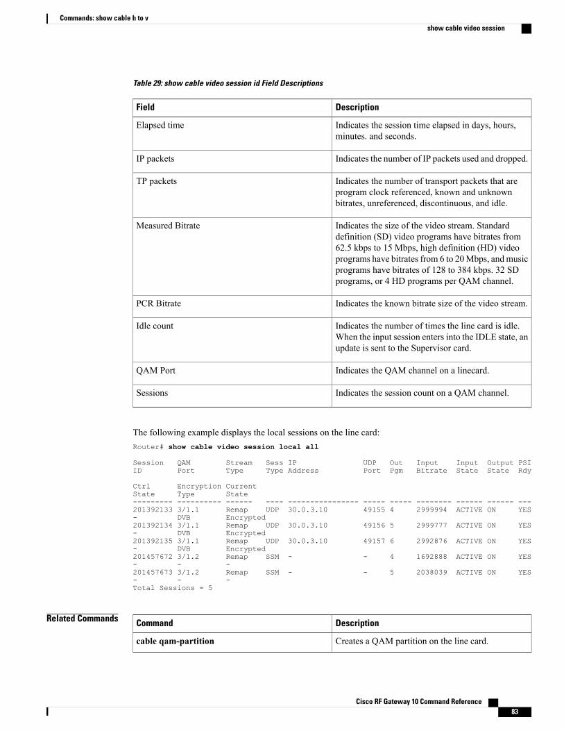
Table 29: show cable video session id Field Descriptions
DescriptionField
Indicates the session time elapsed in days, hours,minutes. and seconds.
Elapsed time
Indicates the number of IP packets used and dropped.IP packets
Indicates the number of transport packets that areprogram clock referenced, known and unknownbitrates, unreferenced, discontinuous, and idle.
TP packets
Indicates the size of the video stream. Standarddefinition (SD) video programs have bitrates from62.5 kbps to 15 Mbps, high definition (HD) videoprograms have bitrates from 6 to 20Mbps, andmusicprograms have bitrates of 128 to 384 kbps. 32 SDprograms, or 4 HD programs per QAM channel.
Measured Bitrate
Indicates the known bitrate size of the video stream.PCR Bitrate
Indicates the number of times the line card is idle.When the input session enters into the IDLE state, anupdate is sent to the Supervisor card.
Idle count
Indicates the QAM channel on a linecard.QAM Port
Indicates the session count on a QAM channel.Sessions
The following example displays the local sessions on the line card:Router# show cable video session local all
Session QAM Stream Sess IP UDP Out Input Input Output PSIID Port Type Type Address Port Pgm Bitrate State State Rdy
Ctrl Encryption CurrentState Type State--------- ---------- ------ ---- ---------------- ----- ----- -------- ------ ------ ---201392133 3/1.1 Remap UDP 30.0.3.10 49155 4 2999994 ACTIVE ON YES- DVB Encrypted201392134 3/1.1 Remap UDP 30.0.3.10 49156 5 2999777 ACTIVE ON YES- DVB Encrypted201392135 3/1.1 Remap UDP 30.0.3.10 49157 6 2992876 ACTIVE ON YES- DVB Encrypted201457672 3/1.2 Remap SSM - - 4 1692888 ACTIVE ON YES- - -201457673 3/1.2 Remap SSM - - 5 2038039 ACTIVE ON YES- - -Total Sessions = 5
Related Commands DescriptionCommand
Creates a QAM partition on the line card.cable qam-partition
Cisco RF Gateway 10 Command Reference 83
Commands: show cable h to vshow cable video session

Cisco RF Gateway 10 Command Reference84
Commands: show cable h to vshow cable video session
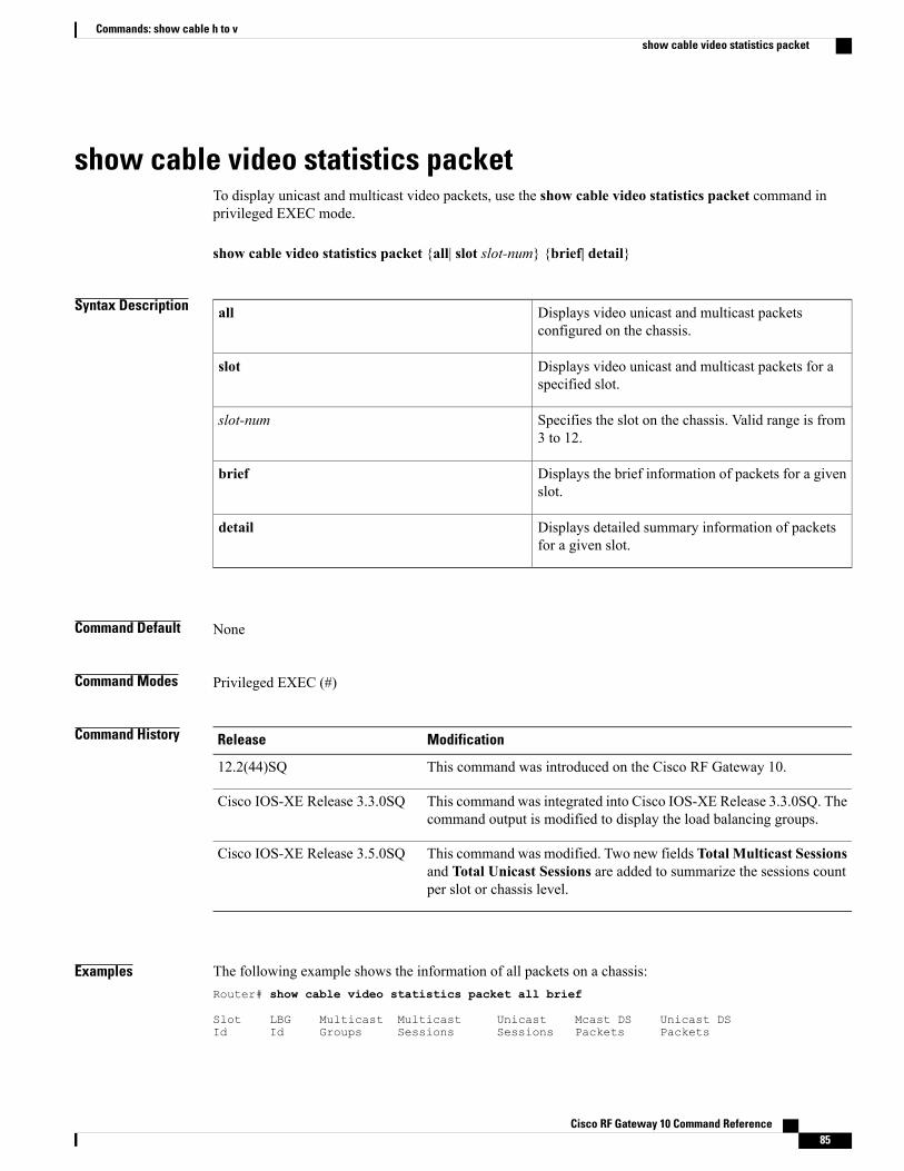
show cable video statistics packetTo display unicast and multicast video packets, use the show cable video statistics packet command inprivileged EXEC mode.
show cable video statistics packet {all| slot slot-num} {brief| detail}
Syntax Description Displays video unicast and multicast packetsconfigured on the chassis.
all
Displays video unicast and multicast packets for aspecified slot.
slot
Specifies the slot on the chassis. Valid range is from3 to 12.
slot-num
Displays the brief information of packets for a givenslot.
brief
Displays detailed summary information of packetsfor a given slot.
detail
Command Default None
Command Modes Privileged EXEC (#)
Command History ModificationRelease
This command was introduced on the Cisco RF Gateway 10.12.2(44)SQ
This command was integrated into Cisco IOS-XE Release 3.3.0SQ. Thecommand output is modified to display the load balancing groups.
Cisco IOS-XE Release 3.3.0SQ
This command was modified. Two new fields Total Multicast Sessionsand Total Unicast Sessions are added to summarize the sessions countper slot or chassis level.
Cisco IOS-XE Release 3.5.0SQ
Examples The following example shows the information of all packets on a chassis:Router# show cable video statistics packet all brief
Slot LBG Multicast Multicast Unicast Mcast DS Unicast DSId Id Groups Sessions Sessions Packets Packets
Cisco RF Gateway 10 Command Reference 85
Commands: show cable h to vshow cable video statistics packet
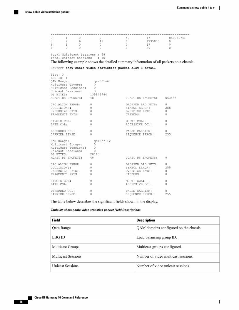
--------------------------------------------------------------------------3 1 0 0 40 17 8588517413 2 6 48 0 1735875 06 1 0 0 0 29 06 2 0 0 0 29 0
Total Multicast Sessions : 48Total Unicast Sessions : 40The following example shows the detailed summary information of all packets on a chassis:Router# show cable video statistics packet slot 3 detail
Slot: 3LBG ID: 1QAM Range: qam3/1-6Multicast Groups: 0Multicast Sessions: 0Unicast Sessions: 3DS BYTES: 135146944MCAST DS PACKETS: 48 UCAST DS PACKETS: 563833
CRC ALIGN ERROR: 0 DROPPED BAD PKTS: 0COLLISIONS: 0 SYMBOL ERROR: 255UNDERSIZE PKTS: 0 OVERSIZE PKTS: 0FRAGMENTS PKTS: 0 JABBERS: 0
SINGLE COL: 0 MULTI COL: 0LATE COL: 0 ACCESSIVE COL: 0
DEFERRED COL: 0 FALSE CARRIER: 0CARRIER SENSE: 0 SEQUENCE ERROR: 255
QAM Range: qam3/7-12Multicast Groups: 0Multicast Sessions: 0Unicast Sessions: 0DS BYTES: 20160MCAST DS PACKETS: 48 UCAST DS PACKETS: 0
CRC ALIGN ERROR: 0 DROPPED BAD PKTS: 0COLLISIONS: 0 SYMBOL ERROR: 255UNDERSIZE PKTS: 0 OVERSIZE PKTS: 0FRAGMENTS PKTS: 0 JABBERS: 0
SINGLE COL: 0 MULTI COL: 0LATE COL: 0 ACCESSIVE COL: 0
DEFERRED COL: 0 FALSE CARRIER: 0CARRIER SENSE: 0 SEQUENCE ERROR: 255
The table below describes the significant fields shown in the display.
Table 30: show cable video statistics packet Field Descriptions
DescriptionField
QAM domains configured on the chassis.Qam Range
Load balancing group ID.LBG ID
Multicast groups configured.Multicast Groups
Number of video multicast sessions.Multicast Sessions
Number of video unicast sessions.Unicast Sessions
Cisco RF Gateway 10 Command Reference86
Commands: show cable h to vshow cable video statistics packet
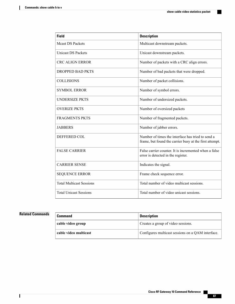
DescriptionField
Multicast downstream packets.Mcast DS Packets
Unicast downstream packets.Unicast DS Packets
Number of packets with a CRC align errors.CRC ALIGN ERROR
Number of bad packets that were dropped.DROPPED BAD PKTS
Number of packet collisions.COLLISIONS
Number of symbol errors.SYMBOL ERROR
Number of undersized packets.UNDERSIZE PKTS
Number of oversized packetsOVERIZE PKTS
Number of fragmented packets.FRAGMENTS PKTS
Number of jabber errors.JABBERS
Number of times the interface has tried to send aframe, but found the carrier busy at the first attempt.
DEFFERED COL
False carrier counter. It is incremented when a falseerror is detected in the register.
FALSE CARRIER
Indicates the signal.CARRIER SENSE
Frame check sequence error.SEQUENCE ERROR
Total number of video multicast sessions.Total Multicast Sessions
Total number of video unicast sessions.Total Unicast Sessions
Related Commands DescriptionCommand
Creates a group of video sessions.cable video group
Configures multicast sessions on a QAM interface.cable video multicast
Cisco RF Gateway 10 Command Reference 87
Commands: show cable h to vshow cable video statistics packet
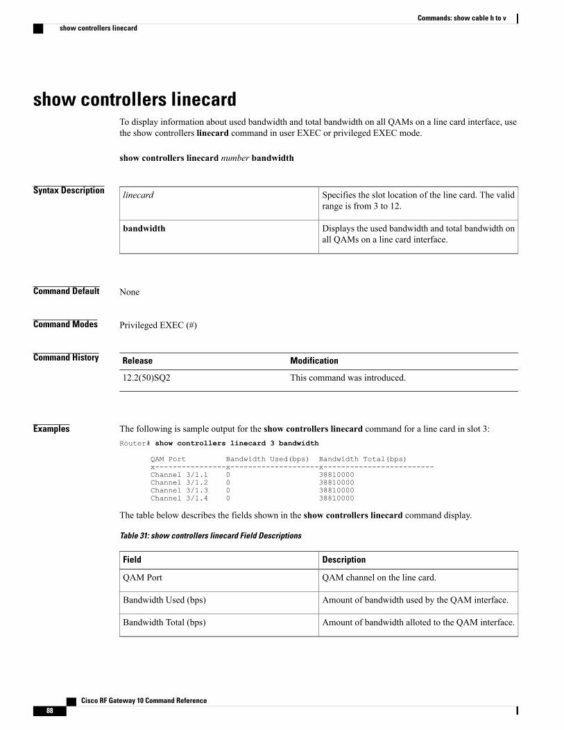
show controllers linecardTo display information about used bandwidth and total bandwidth on all QAMs on a line card interface, usethe show controllers linecard command in user EXEC or privileged EXEC mode.
show controllers linecard number bandwidth
Syntax Description Specifies the slot location of the line card. The validrange is from 3 to 12.
linecard
Displays the used bandwidth and total bandwidth onall QAMs on a line card interface.
bandwidth
Command Default None
Command Modes Privileged EXEC (#)
Command History ModificationRelease
This command was introduced.12.2(50)SQ2
Examples The following is sample output for the show controllers linecard command for a line card in slot 3:Router# show controllers linecard 3 bandwidth
QAM Port Bandwidth Used(bps) Bandwidth Total(bps)x----------------x--------------------x-------------------------Channel 3/1.1 0 38810000Channel 3/1.2 0 38810000Channel 3/1.3 0 38810000Channel 3/1.4 0 38810000
The table below describes the fields shown in the show controllers linecard command display.
Table 31: show controllers linecard Field Descriptions
DescriptionField
QAM channel on the line card.QAM Port
Amount of bandwidth used by the QAM interface.Bandwidth Used (bps)
Amount of bandwidth alloted to the QAM interface.Bandwidth Total (bps)
Cisco RF Gateway 10 Command Reference88
Commands: show cable h to vshow controllers linecard

Related Commands DescriptionCommand
Displays the running configuration of the QAMinterface.
show running-config interface qam
Cisco RF Gateway 10 Command Reference 89
Commands: show cable h to vshow controllers linecard
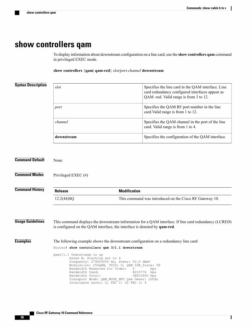
show controllers qamTo display information about downstream configuration on a line card, use the show controllers qam commandin privileged EXEC mode.
show controllers {qam| qam-red} slot/port.channel downstream
Syntax Description Specifies the line card in the QAM interface. Linecard redundancy configured interfaces appear asQAM -red. Valid range is from 3 to 12.
slot
Specifies the QAM RF port number in the linecard.Valid range is from 1 to 12.
port
Specifies the QAM channel in the port of the linecard. Valid range is from 1 to 4.
channel
Specifies the configuration of the QAM interface.downstream
Command Default None
Command Modes Privileged EXEC (#)
Command History ModificationRelease
This command was introduced on the Cisco RF Gateway 10.12.2(44)SQ
Usage Guidelines This command displays the downstream information for a QAM interface. If line card redundancy (LCRED)is configured on the QAM interface, the interface is denoted by qam-red.
Examples The following example shows the downstream configuration on a redundancy line card:Router# show controllers qam 3/1.1 downstream
Qam3/1.1 Downstream is upAnnex B, Stacking set to 4Frequency: 279000000 Hz, Power: 50.0 dBmVModulation: 256QAM, TSID: 0, QAM IDB_State: UPBandwidth Reserved for Video: 0 bpsBandwidth Used: 8223776 bpsBandwidth Total: 38810000 bpsTransport Mode: QAM_MODE_MPT Qam Owner: LOCALInterleave Level: 2, FEC I: 32 FEC J: 4
Cisco RF Gateway 10 Command Reference90
Commands: show cable h to vshow controllers qam

The table below describes the significant fields shown in the display.
Table 32: show controllers qam Field Descriptions
DescriptionField
Indicates whether the interface hardware is currentlyactive or disabled by the administrator.
Downstream
Indicates the annex for the RF downstream channel.Annex
Indicates the stacking level set on the QAM interface.Stacking
Indicates the modulation level of the QAM.Modulation
Indicates the TSID value set on the QAM.TSID
Indicates the state of the QAM interface.QAM_IDB_State
Amount of bandwidth alloted for video.Bandwidth Reserved for video
Amount of bandwidth used by the QAM interface.Bandwidth Used
Amount of bandwidth alloted to the QAM interface.Bandwidth Total
Indicates the mode on the QAM.Transport Mode
Indicates the frequency interleave level on the QAM.Interleave Level
Length of the forward error correction in bytes. Therange is 0 to 10 bytes; a value of 0 implies no forwarderror correction.
FEC
Related Commands DescriptionCommand
Displays the running configuration of the QAMinterface.
show running-config interface qam
Cisco RF Gateway 10 Command Reference 91
Commands: show cable h to vshow controllers qam
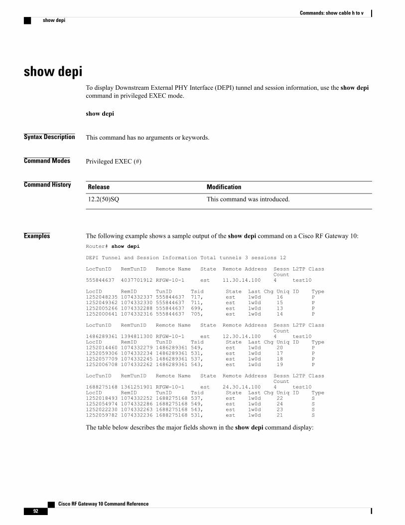
show depiTo display Downstream External PHY Interface (DEPI) tunnel and session information, use the show depicommand in privileged EXEC mode.
show depi
Syntax Description This command has no arguments or keywords.
Command Modes Privileged EXEC (#)
Command History ModificationRelease
This command was introduced.12.2(50)SQ
Examples The following example shows a sample output of the show depi command on a Cisco RF Gateway 10:Router# show depi
DEPI Tunnel and Session Information Total tunnels 3 sessions 12
LocTunID RemTunID Remote Name State Remote Address Sessn L2TP ClassCount
555844637 4037701912 RFGW-10-1 est 11.30.14.100 4 test10
LocID RemID TunID Tsid State Last Chg Uniq ID Type1252048235 1074332337 555844637 717, est 1w0d 16 P1252049362 1074332330 555844637 711, est 1w0d 15 P1252005266 1074332288 555844637 699, est 1w0d 13 P1252000641 1074332316 555844637 705, est 1w0d 14 P
LocTunID RemTunID Remote Name State Remote Address Sessn L2TP ClassCount
1486289361 1394811300 RFGW-10-1 est 12.30.14.100 4 test10LocID RemID TunID Tsid State Last Chg Uniq ID Type1252014460 1074332279 1486289361 549, est 1w0d 20 P1252059306 1074332234 1486289361 531, est 1w0d 17 P1252057709 1074332245 1486289361 537, est 1w0d 18 P1252006708 1074332262 1486289361 543, est 1w0d 19 P
LocTunID RemTunID Remote Name State Remote Address Sessn L2TP ClassCount
1688275168 1361251901 RFGW-10-1 est 24.30.14.100 4 test10LocID RemID TunID Tsid State Last Chg Uniq ID Type1252018493 1074332252 1688275168 537, est 1w0d 22 S1252054974 1074332286 1688275168 549, est 1w0d 24 S1252022230 1074332263 1688275168 543, est 1w0d 23 S1252059782 1074332236 1688275168 531, est 1w0d 21 S
The table below describes the major fields shown in the show depi command display:
Cisco RF Gateway 10 Command Reference92
Commands: show cable h to vshow depi
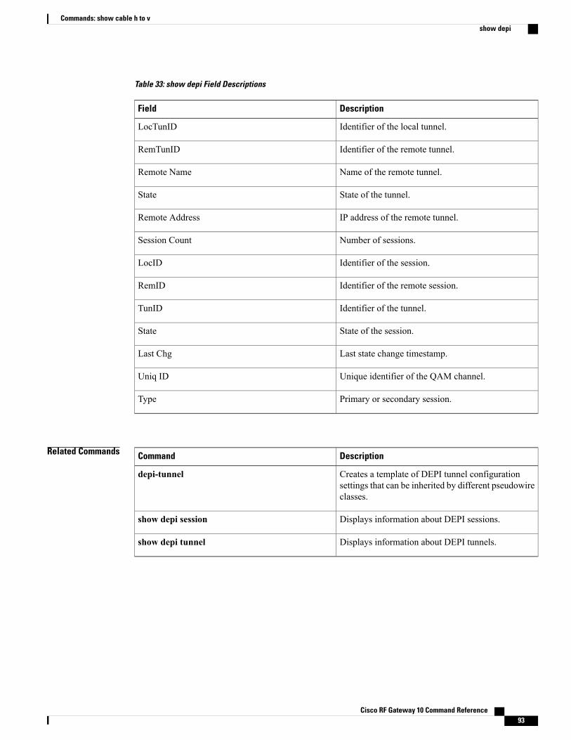
Table 33: show depi Field Descriptions
DescriptionField
Identifier of the local tunnel.LocTunID
Identifier of the remote tunnel.RemTunID
Name of the remote tunnel.Remote Name
State of the tunnel.State
IP address of the remote tunnel.Remote Address
Number of sessions.Session Count
Identifier of the session.LocID
Identifier of the remote session.RemID
Identifier of the tunnel.TunID
State of the session.State
Last state change timestamp.Last Chg
Unique identifier of the QAM channel.Uniq ID
Primary or secondary session.Type
Related Commands DescriptionCommand
Creates a template of DEPI tunnel configurationsettings that can be inherited by different pseudowireclasses.
depi-tunnel
Displays information about DEPI sessions.show depi session
Displays information about DEPI tunnels.show depi tunnel
Cisco RF Gateway 10 Command Reference 93
Commands: show cable h to vshow depi

show depi sessionTo display information about Downstream External PHY Interface (DEPI) sessions, use the show depi sessioncommand in privileged EXEC mode.
show depi session [session-id verbose| configured| name session-name [verbose]| primary| secondary|tsid ts-id]
Syntax Description (Optional) Local session ID value. The allowed rangeis from 1 to 4294967295.
session-id
(Optional) Displays detailed DEPI tunnel or sessioninformation.
verbose
(Optional) Displays all the DEPI sessions configuredand their state. The states are IDLE and ACTIVE.
configured
(Optional) Specifies the name of the DEPI session.name session-name
(Optional) Specifies the primary DEPI session.primary
(Optional) Specifies the backup DEPI session.secondary
(Optional) Specifies the Transport Stream Identifier(TSID).
tsid ts-id
Command Default None
Command Modes Privileged EXEC (#)
Command History ModificationRelease
This command was introduced.12.2(50)SQ
This commandwasmodified. The following keywords were added to thiscommand:
• configured
• name
• primary
• secondary
• tsid
12.2(50)SQ2
Cisco RF Gateway 10 Command Reference94
Commands: show cable h to vshow depi session
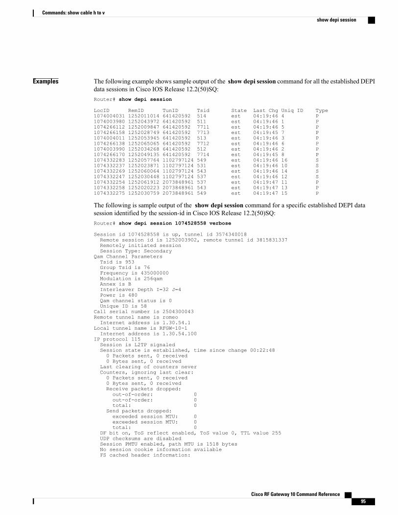
Examples The following example shows sample output of the show depi session command for all the established DEPIdata sessions in Cisco IOS Release 12.2(50)SQ:Router# show depi session
LocID RemID TunID Tsid State Last Chg Uniq ID Type1074004031 1252011014 641420592 514 est 04:19:46 4 P1074003980 1252043972 641420592 511 est 04:19:46 1 P1074266112 1252009847 641420592 7711 est 04:19:46 5 P1074266158 1252028749 641420592 7713 est 04:19:45 7 P1074004011 1252053945 641420592 513 est 04:19:46 3 P1074266138 1252065065 641420592 7712 est 04:19:46 6 P1074003990 1252034268 641420592 512 est 04:19:46 2 P1074266170 1252049135 641420592 7714 est 04:19:45 8 P1074332283 1252057764 1102797124 549 est 04:19:46 16 S1074332237 1252023871 1102797124 531 est 04:19:46 10 S1074332269 1252060064 1102797124 543 est 04:19:46 14 S1074332247 1252030448 1102797124 537 est 04:19:46 12 S1074332254 1252061912 2073848961 537 est 04:19:47 11 P1074332258 1252020223 2073848961 543 est 04:19:47 13 P1074332275 1252030759 2073848961 549 est 04:19:47 15 P
The following is sample output of the show depi session command for a specific established DEPI datasession identified by the session-id in Cisco IOS Release 12.2(50)SQ:Router# show depi session 1074528558 verbose
Session id 1074528558 is up, tunnel id 3574340018Remote session id is 1252003902, remote tunnel id 3815831337Remotely initiated sessionSession Type: Secondary
Qam Channel ParametersTsid is 953Group Tsid is 76Frequency is 435000000Modulation is 256qamAnnex is BInterleaver Depth I=32 J=4Power is 480Qam channel status is 0Unique ID is 58
Call serial number is 2504300043Remote tunnel name is romeoInternet address is 1.30.54.1
Local tunnel name is RFGW-10-1Internet address is 1.30.54.100
IP protocol 115Session is L2TP signaledSession state is established, time since change 00:22:480 Packets sent, 0 received0 Bytes sent, 0 received
Last clearing of counters neverCounters, ignoring last clear:0 Packets sent, 0 received0 Bytes sent, 0 receivedReceive packets dropped:out-of-order: 0out-of-order: 0total: 0
Send packets dropped:exceeded session MTU: 0exceeded session MTU: 0total: 0
DF bit on, ToS reflect enabled, ToS value 0, TTL value 255UDP checksums are disabledSession PMTU enabled, path MTU is 1518 bytesNo session cookie information availableFS cached header information:
Cisco RF Gateway 10 Command Reference 95
Commands: show cable h to vshow depi session
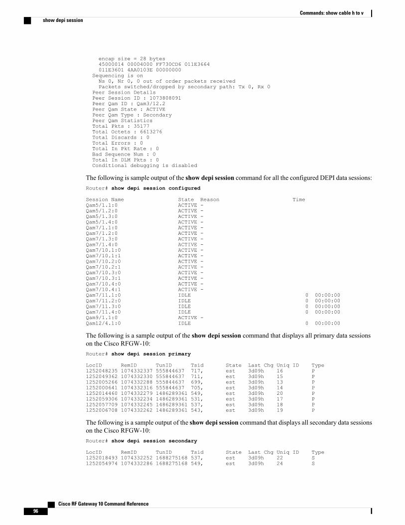
encap size = 28 bytes45000014 00004000 FF730CD6 011E3664011E3601 4AA0103E 00000000
Sequencing is onNs 0, Nr 0, 0 out of order packets receivedPackets switched/dropped by secondary path: Tx 0, Rx 0
Peer Session DetailsPeer Session ID : 1073808091Peer Qam ID : Qam3/12.2Peer Qam State : ACTIVEPeer Qam Type : SecondaryPeer Qam StatisticsTotal Pkts : 35177Total Octets : 6613276Total Discards : 0Total Errors : 0Total In Pkt Rate : 0Bad Sequence Num : 0Total In DLM Pkts : 0Conditional debugging is disabled
The following is sample output of the show depi session command for all the configured DEPI data sessions:Router# show depi session configured
Session Name State Reason TimeQam5/1.1:0 ACTIVE -Qam5/1.2:0 ACTIVE -Qam5/1.3:0 ACTIVE -Qam5/1.4:0 ACTIVE -Qam7/1.1:0 ACTIVE -Qam7/1.2:0 ACTIVE -Qam7/1.3:0 ACTIVE -Qam7/1.4:0 ACTIVE -Qam7/10.1:0 ACTIVE -Qam7/10.1:1 ACTIVE -Qam7/10.2:0 ACTIVE -Qam7/10.2:1 ACTIVE -Qam7/10.3:0 ACTIVE -Qam7/10.3:1 ACTIVE -Qam7/10.4:0 ACTIVE -Qam7/10.4:1 ACTIVE -Qam7/11.1:0 IDLE 0 00:00:00Qam7/11.2:0 IDLE 0 00:00:00Qam7/11.3:0 IDLE 0 00:00:00Qam7/11.4:0 IDLE 0 00:00:00Qam9/1.1:0 ACTIVE -Qam12/4.1:0 IDLE 0 00:00:00
The following is a sample output of the show depi session command that displays all primary data sessionson the Cisco RFGW-10:Router# show depi session primary
LocID RemID TunID Tsid State Last Chg Uniq ID Type1252048235 1074332337 555844637 717, est 3d09h 16 P1252049362 1074332330 555844637 711, est 3d09h 15 P1252005266 1074332288 555844637 699, est 3d09h 13 P1252000641 1074332316 555844637 705, est 3d09h 14 P1252014460 1074332279 1486289361 549, est 3d09h 20 P1252059306 1074332234 1486289361 531, est 3d09h 17 P1252057709 1074332245 1486289361 537, est 3d09h 18 P1252006708 1074332262 1486289361 543, est 3d09h 19 P
The following is a sample output of the show depi session command that displays all secondary data sessionson the Cisco RFGW-10:Router# show depi session secondary
LocID RemID TunID Tsid State Last Chg Uniq ID Type1252018493 1074332252 1688275168 537, est 3d09h 22 S1252054974 1074332286 1688275168 549, est 3d09h 24 S
Cisco RF Gateway 10 Command Reference96
Commands: show cable h to vshow depi session
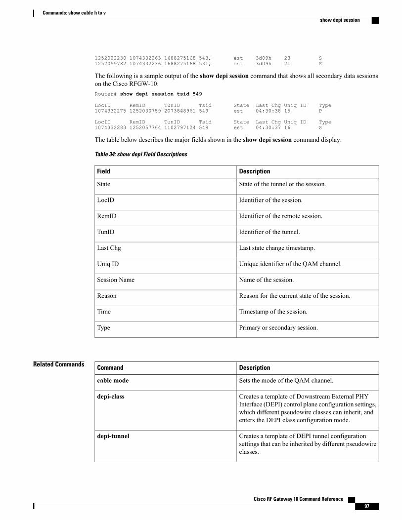
1252022230 1074332263 1688275168 543, est 3d09h 23 S1252059782 1074332236 1688275168 531, est 3d09h 21 S
The following is a sample output of the show depi session command that shows all secondary data sessionson the Cisco RFGW-10:Router# show depi session tsid 549
LocID RemID TunID Tsid State Last Chg Uniq ID Type1074332275 1252030759 2073848961 549 est 04:30:38 15 P
LocID RemID TunID Tsid State Last Chg Uniq ID Type1074332283 1252057764 1102797124 549 est 04:30:37 16 S
The table below describes the major fields shown in the show depi session command display:
Table 34: show depi Field Descriptions
DescriptionField
State of the tunnel or the session.State
Identifier of the session.LocID
Identifier of the remote session.RemID
Identifier of the tunnel.TunID
Last state change timestamp.Last Chg
Unique identifier of the QAM channel.Uniq ID
Name of the session.Session Name
Reason for the current state of the session.Reason
Timestamp of the session.Time
Primary or secondary session.Type
Related Commands DescriptionCommand
Sets the mode of the QAM channel.cable mode
Creates a template of Downstream External PHYInterface (DEPI) control plane configuration settings,which different pseudowire classes can inherit, andenters the DEPI class configuration mode.
depi-class
Creates a template of DEPI tunnel configurationsettings that can be inherited by different pseudowireclasses.
depi-tunnel
Cisco RF Gateway 10 Command Reference 97
Commands: show cable h to vshow depi session
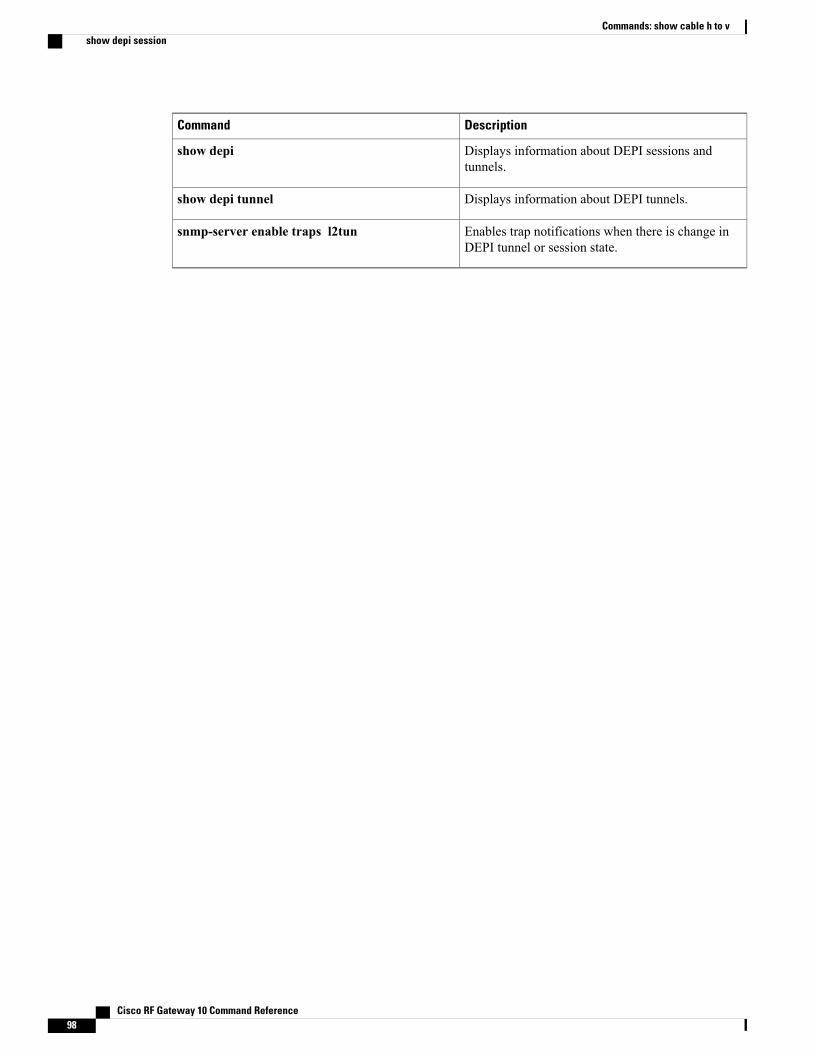
DescriptionCommand
Displays information about DEPI sessions andtunnels.
show depi
Displays information about DEPI tunnels.show depi tunnel
Enables trap notifications when there is change inDEPI tunnel or session state.
snmp-server enable traps l2tun
Cisco RF Gateway 10 Command Reference98
Commands: show cable h to vshow depi session
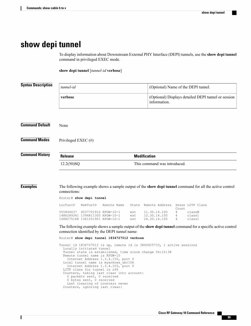
show depi tunnelTo display information about Downstream External PHY Interface (DEPI) tunnels, use the show depi tunnelcommand in privileged EXEC mode.
show depi tunnel [tunnel-id verbose]
Syntax Description (Optional) Name of the DEPI tunnel.tunnel-id
(Optional) Displays detailed DEPI tunnel or sessioninformation.
verbose
Command Default None
Command Modes Privileged EXEC (#)
Command History ModificationRelease
This command was introduced.12.2(50)SQ
Examples The following example shows a sample output of the show depi tunnel command for all the active controlconnections:Router# show depi tunnel
LocTunID RemTunID Remote Name State Remote Address Sessn L2TP ClassCount
555844637 4037701912 RFGW-10-1 est 11.30.14.100 4 classM1486289361 1394811300 RFGW-10-1 est 12.30.14.100 4 class11688275168 1361251901 RFGW-10-1 est 24.30.14.100 4 class1
The following example shows a sample output of the show depi tunnel command for a specific active controlconnection identified by the DEPI tunnel name:Router# show depi tunnel 1834727012 verbose
Tunnel id 1834727012 is up, remote id is 3849925733, 1 active sessionsLocally initiated tunnelTunnel state is established, time since change 04:10:38Remote tunnel name is RFGW-10Internet Address 1.3.4.155, port 0
Local tunnel name is myankows_ubr10kInternet Address 1.3.4.103, port 0
L2TP class for tunnel is rf6Counters, taking last clear into account:0 packets sent, 0 received0 bytes sent, 0 receivedLast clearing of counters never
Counters, ignoring last clear:
Cisco RF Gateway 10 Command Reference 99
Commands: show cable h to vshow depi tunnel

0 packets sent, 0 received0 bytes sent, 0 received
Control Ns 255, Nr 254Local RWS 1024 (default), Remote RWS 8192Control channel Congestion Control is enabledCongestion Window size, Cwnd 256Slow Start threshold, Ssthresh 8192Mode of operation is Slow Start
Retransmission time 1, max 1 secondsUnsent queuesize 0, max 0Resend queuesize 0, max 2Total resends 0, ZLB ACKs sent 252Total peer authentication failures 0Current no session pak queue check 0 of 5Retransmit time distribution: 0 0 0 0 0 0 0 0 0Control message authentication is disabled
The table below describes the major fields shown in the show depi tunnel command display:
Table 35: show depi Field Descriptions
DescriptionField
Identifier of the local tunnel.LocTunID
Identifier of the remote tunnel.RemTunID
Name of the remote tunnel.Remote Name
State of the tunnel.State
IP address of the remote tunnel.Remote Address
Number of sessions.Session Count
L2TP class name for the tunnel.L2TP Class
Related Commands DescriptionCommand
Creates a template of DEPI tunnel configurationsettings that can be inherited by different pseudowireclasses.
depi-tunnel
Binds the depi-tunnel to an rf-channel on a sharedport adapter (SPA).
rf-channel depi-tunnel
Enters controller configuration mode to configure theSPA controller.
controller modular-cable
Displays information about DEPI sessions andtunnels.
show depi
Displays information about DEPI sessions.show depi session
Cisco RF Gateway 10 Command Reference100
Commands: show cable h to vshow depi tunnel
DescriptionCommand
Enables trap notifications when there is change inDEPI tunnel or session state.
snmp-server enable traps l2tun
Cisco RF Gateway 10 Command Reference 101
Commands: show cable h to vshow depi tunnel
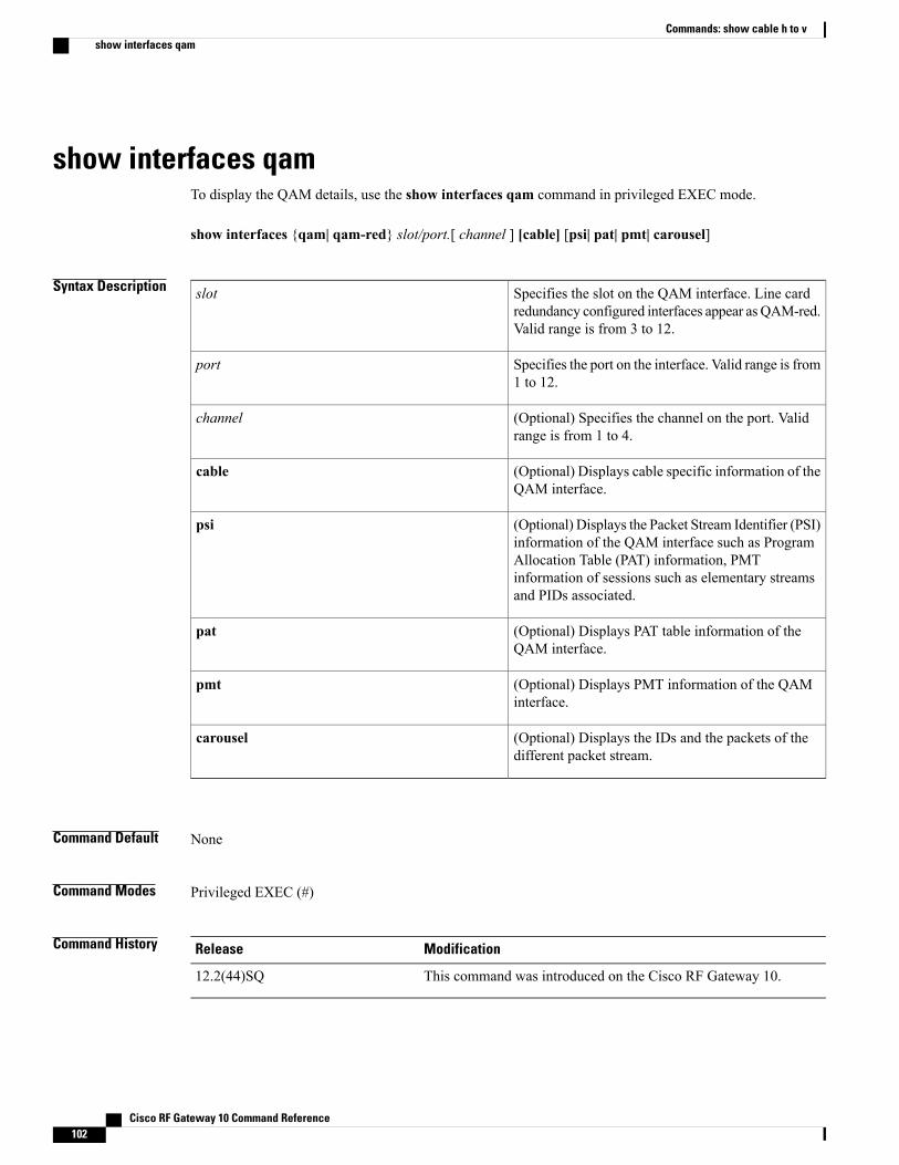
show interfaces qamTo display the QAM details, use the show interfaces qam command in privileged EXEC mode.
show interfaces {qam| qam-red} slot/port.[ channel ] [cable] [psi| pat| pmt| carousel]
Syntax Description Specifies the slot on the QAM interface. Line cardredundancy configured interfaces appear as QAM-red.Valid range is from 3 to 12.
slot
Specifies the port on the interface. Valid range is from1 to 12.
port
(Optional) Specifies the channel on the port. Validrange is from 1 to 4.
channel
(Optional) Displays cable specific information of theQAM interface.
cable
(Optional) Displays the Packet Stream Identifier (PSI)information of the QAM interface such as ProgramAllocation Table (PAT) information, PMTinformation of sessions such as elementary streamsand PIDs associated.
psi
(Optional) Displays PAT table information of theQAM interface.
pat
(Optional) Displays PMT information of the QAMinterface.
pmt
(Optional) Displays the IDs and the packets of thedifferent packet stream.
carousel
Command Default None
Command Modes Privileged EXEC (#)
Command History ModificationRelease
This command was introduced on the Cisco RF Gateway 10.12.2(44)SQ
Cisco RF Gateway 10 Command Reference102
Commands: show cable h to vshow interfaces qam

Usage Guidelines This command displays packet and byte counts and protocol information of the QAM interface. PSI, PMT,and PAT information details are not displayed.
The Program Allocation Table (PAT) is the master table that contains the list of PIDs for all programs on theoutput stream of the QAM.
The show interfaces qam slot/port.channel psi and show interfaces qam slot/port.channel pmt commandscould potentially create a large amount of output and are recommended to be used sparingly.
Note
Examples The following example displays the protocol and byte information on QAM slot 3:Router# show interfaces qam 3/1
Qam3/1 is up, line protocol is upHardware is RFGW-48DS Line Card - QAM PortMTU 1464 bytes, BW 107880 Kbit, DLY 0 usec,
reliability 0/255, txload 1/255, rxload 1/255Encapsulation QAM, loopback not setKeepalive set (10 sec)Last input never, output never, output hang neverLast clearing of "show interface" counters neverInput queue: 0/75/0/0 (size/max/drops/flushes); Total output drops: 05 minute input rate 0 bits/sec, 0 packets/sec5 minute output rate 0 bits/sec, 0 packets/sec
0 packets input, 0 bytes, 0 no bufferReceived 0 broadcasts (0 IP multicasts)0 runts, 0 giants, 0 throttles0 input errors, 0 CRC, 0 frame, 0 overrun, 0 ignored, 0 abort
8439807 packets output, 67518456 bytes 0 underruns0 output errors, 0 collisions, 0 interface resets0 output buffer failures, 0 output buffers swapped out
The table below describes the significant fields shown in the display.
Table 36: show interfaces qam Field Descriptions
DescriptionField
Indicates whether the interface hardware is currentlyactive or taken down by the administrator.
QAM slot/port
Indicates whether the software processes that handlethe line protocol believe the interface is usable or ifit has been taken down by the administrator.
line protocol
Hardware type and address.Hardware
Maximum transmission unit (MTU) of the interface.MTU
Bandwidth of the interface in kilobits per second.BW
Delay of the interface in microseconds.DLY
Cisco RF Gateway 10 Command Reference 103
Commands: show cable h to vshow interfaces qam

DescriptionField
Reliability of the interface as a fraction of 255,calculated as an exponential average over 5 minutes.(For example, 255/255 is 100-percent reliability)
reliability
Load on the interface as a fraction of 255, calculatedas an exponential average over 5 minutes. (Forexample, 255/255 is complete saturation)
txload
Load on the interface as a fraction of 255, calculatedas an exponential average over 5 minutes. (Forexample, 255/255 is complete saturation)
rxload
Encapsulation method assigned to this interface.Encapsulation
Indicates the time for the keep alive set.Keepalive set
Number of hours, minutes, and seconds since the lastpacket was successfully received by an interface.
Last input
Number of hours, minutes, and seconds since the lastpacket was successfully sent by an interface.
output
Time at which the counters that measure cumulativestatistics (such as number of bytes sent and received)were last reset to zero.
Last clearing of "show interfaces" counters
Number of packets in the input queue. The format ofthis number is A/B, where A indicates the number ofpackets in the queue, and B indicates the maximumnumber of packets allowed in the queue.
Input queue
Indicates the number of packets dropped because ofa full queue.
Total output drops
Cisco RF Gateway 10 Command Reference104
Commands: show cable h to vshow interfaces qam
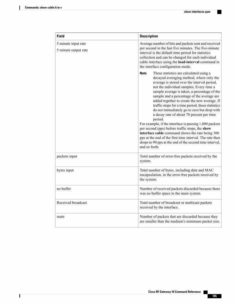
DescriptionField
Average number of bits and packets sent and receivedper second in the last five minutes. The five-minuteinterval is the default time period for statisticscollection and can be changed for each individualcable interface using the load-interval command inthe interface configuration mode.
These statistics are calculated using adecayed averaging method, where only theaverage is stored over the interval period,not the individual samples. Every time asample average is taken, a percentage of thesample and a percentage of the average areadded together to create the new average. Iftraffic stops for a time period, these statisticsdo not immediately go to zero but drop witha decay rate of about 70 percent per timeperiod.
Note
For example, if the interface is passing 1,000 packetsper second (pps) before traffic stops, the showinterface cable command shows the rate being 300pps at the end of the first time interval. The rate thendrops to 90 pps at the end of the second time interval,and so forth.
5 minute input rate
5 minute output rate
Total number of error-free packets received by thesystem.
packets input
Total number of bytes, including data and MACencapsulation, in the error-free packets received bythe system.
bytes input
Number of received packets discarded because therewas no buffer space in the main system.
no buffer
Total number of broadcast or multicast packetsreceived by the interface.
Received broadcast
Number of packets that are discarded because theyare smaller than the medium’s minimum packet size.
runts
Cisco RF Gateway 10 Command Reference 105
Commands: show cable h to vshow interfaces qam
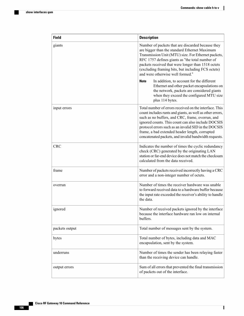
DescriptionField
Number of packets that are discarded because theyare bigger than the standard Ethernet MaximumTransmission Unit (MTU) size. For Ethernet packets,RFC 1757 defines giants as “the total number ofpackets received that were longer than 1518 octets(excluding framing bits, but including FCS octets)and were otherwise well formed.”
In addition, to account for the differentEthernet and other packet encapsulations onthe network, packets are considered giantswhen they exceed the configured MTU sizeplus 114 bytes.
Note
giants
Total number of errors received on the interface. Thiscount includes runts and giants, as well as other errors,such as no buffers, and CRC, frame, overrun, andignored counts. This count can also include DOCSISprotocol errors such as an invalid SID in the DOCSISframe, a bad extended header length, corruptedconcatenated packets, and invalid bandwidth requests.
input errors
Indicates the number of times the cyclic redundancycheck (CRC) generated by the originating LANstation or far-end device does not match the checksumcalculated from the data received.
CRC
Number of packets received incorrectly having a CRCerror and a non-integer number of octets.
frame
Number of times the receiver hardware was unableto forward received data to a hardware buffer becausethe input rate exceeded the receiver’s ability to handlethe data.
overrun
Number of received packets ignored by the interfacebecause the interface hardware ran low on internalbuffers.
ignored
Total number of messages sent by the system.packets output
Total number of bytes, including data and MACencapsulation, sent by the system.
bytes
Number of times the sender has been relaying fasterthan the receiving device can handle.
underruns
Sum of all errors that prevented the final transmissionof packets out of the interface.
output errors
Cisco RF Gateway 10 Command Reference106
Commands: show cable h to vshow interfaces qam
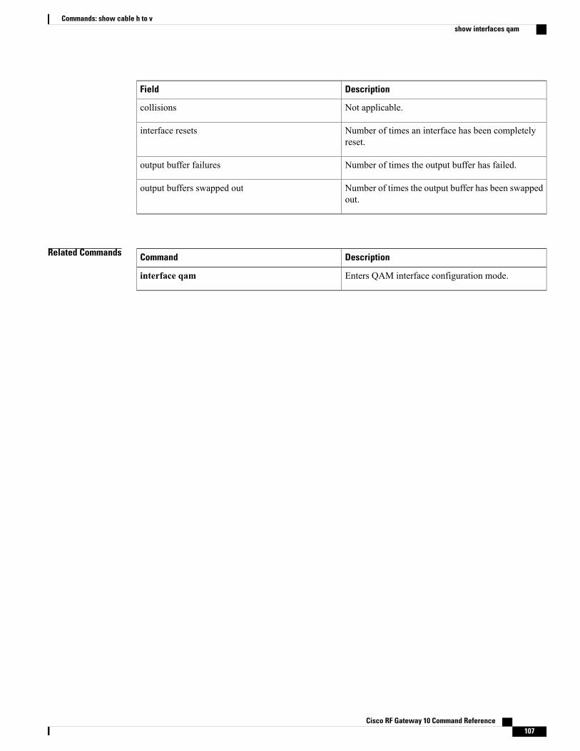
DescriptionField
Not applicable.collisions
Number of times an interface has been completelyreset.
interface resets
Number of times the output buffer has failed.output buffer failures
Number of times the output buffer has been swappedout.
output buffers swapped out
Related Commands DescriptionCommand
Enters QAM interface configuration mode.interface qam
Cisco RF Gateway 10 Command Reference 107
Commands: show cable h to vshow interfaces qam
show redundancyTo display the current redundancy status, use the show redundancy command in user EXEC or privilegedEXEC mode.
show redundancy [clients| counters| history| states]
Syntax Description (Optional) Displays the Redundancy Facility clientlist.
clients
(Optional) Displays RF operational counters.counters
(Optional) Summarizes RF history.history
(Optional) Displays RF states for active and standbycards.
states
Command Default None
Command Modes User EXEC (>)
Privileged EXEC (#)
Command History ModificationRelease
This commandwas integrated into Cisco IOS Release 12.2(44)SQ. Supportfor the Cisco RF Gateway 10 was added.
12.2(44)SQ
Usage Guidelines The show redundancy command shows whether the Supervisor A slot or Supervisor B slot contains theactive (primary) Supervisor card, the status of the standby (secondary) Supervisor card, and the standbySupervisor card boot variable values and configuration register.
The redundancy mode set on the Supervisor can also be seen.
The show redundancy command always shows the correct location of the active Supervisor card. Theother Supervisor slot will always bemarked as secondary, even if a standby Supervisor card is not installed.
Note
Cisco RF Gateway 10 Command Reference108
Commands: show cable h to vshow redundancy
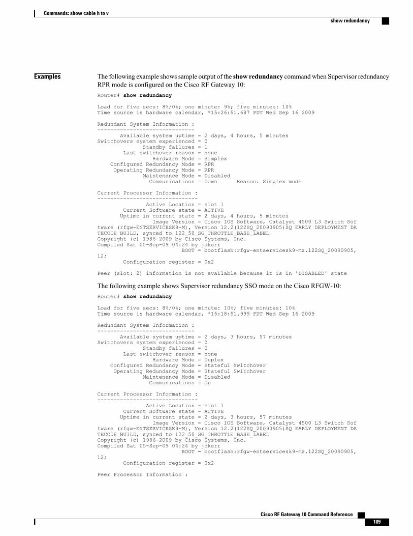
Examples The following example shows sample output of the show redundancy commandwhen Supervisor redundancyRPR mode is configured on the Cisco RF Gateway 10:Router# show redundancy
Load for five secs: 8%/0%; one minute: 9%; five minutes: 10%Time source is hardware calendar, *15:26:51.687 PDT Wed Sep 16 2009
Redundant System Information :------------------------------
Available system uptime = 2 days, 4 hours, 5 minutesSwitchovers system experienced = 0
Standby failures = 1Last switchover reason = none
Hardware Mode = SimplexConfigured Redundancy Mode = RPROperating Redundancy Mode = RPR
Maintenance Mode = DisabledCommunications = Down Reason: Simplex mode
Current Processor Information :-------------------------------
Active Location = slot 1Current Software state = ACTIVEUptime in current state = 2 days, 4 hours, 5 minutes
Image Version = Cisco IOS Software, Catalyst 4500 L3 Switch Software (rfgw-ENTSERVICESK9-M), Version 12.2(122SQ_20090905)SQ EARLY DEPLOYMENT DATECODE BUILD, synced to 122_50_SG_THROTTLE_BASE_LABELCopyright (c) 1986-2009 by Cisco Systems, Inc.Compiled Sat 05-Sep-09 04:24 by jdkerr
BOOT = bootflash:rfgw-entservicesk9-mz.122SQ_20090905,12;
Configuration register = 0x2
Peer (slot: 2) information is not available because it is in 'DISABLED' state
The following example shows Supervisor redundancy SSO mode on the Cisco RFGW-10:Router# show redundancy
Load for five secs: 8%/0%; one minute: 10%; five minutes: 10%Time source is hardware calendar, *15:18:51.999 PDT Wed Sep 16 2009
Redundant System Information :------------------------------
Available system uptime = 2 days, 3 hours, 57 minutesSwitchovers system experienced = 0
Standby failures = 0Last switchover reason = none
Hardware Mode = DuplexConfigured Redundancy Mode = Stateful SwitchoverOperating Redundancy Mode = Stateful Switchover
Maintenance Mode = DisabledCommunications = Up
Current Processor Information :-------------------------------
Active Location = slot 1Current Software state = ACTIVEUptime in current state = 2 days, 3 hours, 57 minutes
Image Version = Cisco IOS Software, Catalyst 4500 L3 Switch Software (rfgw-ENTSERVICESK9-M), Version 12.2(122SQ_20090905)SQ EARLY DEPLOYMENT DATECODE BUILD, synced to 122_50_SG_THROTTLE_BASE_LABELCopyright (c) 1986-2009 by Cisco Systems, Inc.Compiled Sat 05-Sep-09 04:24 by jdkerr
BOOT = bootflash:rfgw-entservicesk9-mz.122SQ_20090905,12;
Configuration register = 0x2
Peer Processor Information :
Cisco RF Gateway 10 Command Reference 109
Commands: show cable h to vshow redundancy

----------------------------Standby Location = slot 2
Current Software state = STANDBY HOTUptime in current state = 2 days, 3 hours, 56 minutes
Image Version = Cisco IOS Software, Catalyst 4500 L3 Switch Software (rfgw-ENTSERVICESK9-M), Version 12.2(122SQ_20090905)SQ EARLY DEPLOYMENT DATECODE BUILD, synced to 122_50_SG_THROTTLE_BASE_LABELCopyright (c) 1986-2009 by Cisco Systems, Inc.Compiled Sat 05-Sep-09 04:2
BOOT = bootflash:rfgw-entservicesk9-mz.122SQ_20090905,12;
Configuration register = 0x2Router
Clients Display
The following example shows a sample output of the show redundancy clients command:Router# show redundancy clientsclientID = 0 clientSeq = 0 RF_INTERNAL_MSGclientID = 25 clientSeq = 130 CHKPT RFclientID = 5 clientSeq = 170 RFS clientclientID = 50 clientSeq = 530 Slot RFclientID = 65000 clientSeq = 65000 RF_LAST_CLIENT
The table below describes the significant fields shown in the display.
Table 37: show redundancy clients Field Descriptions
DescriptionField
Client ID number.clientID
Client notification sequence number.clientSeq
Counters Display
The following example shows a sample output of the show redundancy counters command:Router# show redundancy counters
Redundancy Facility OMscomm link up = 1
comm link down down = 0
invalid client tx = 0null tx by client = 0
tx failures = 0tx msg length invalid = 0
client not rxing msgs = 0rx peer msg routing errors = 0
null peer msg rx = 0errored peer msg rx = 0
buffers tx = 1009tx buffers unavailable = 0
buffers rx = 1006buffer release errors = 0
duplicate client registers = 0failed to register client = 0
Invalid client syncs = 0
History Display
Cisco RF Gateway 10 Command Reference110
Commands: show cable h to vshow redundancy
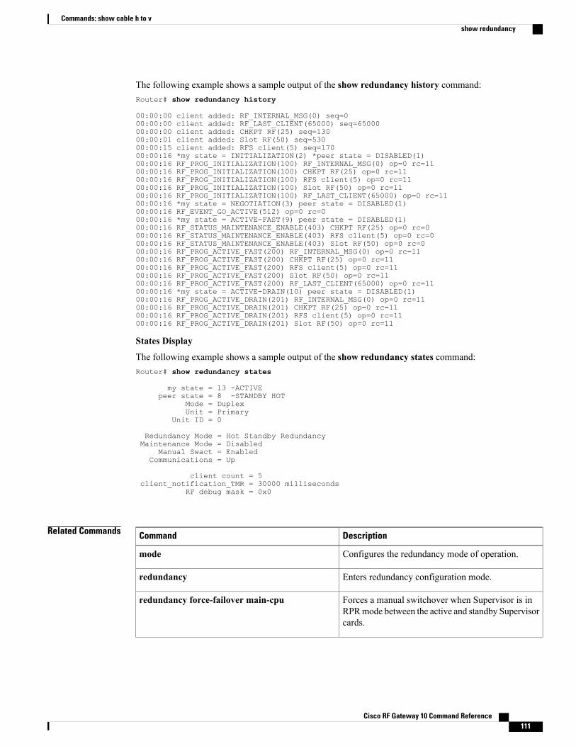
The following example shows a sample output of the show redundancy history command:Router# show redundancy history
00:00:00 client added: RF_INTERNAL_MSG(0) seq=000:00:00 client added: RF_LAST_CLIENT(65000) seq=6500000:00:00 client added: CHKPT RF(25) seq=13000:00:01 client added: Slot RF(50) seq=53000:00:15 client added: RFS client(5) seq=17000:00:16 *my state = INITIALIZATION(2) *peer state = DISABLED(1)00:00:16 RF_PROG_INITIALIZATION(100) RF_INTERNAL_MSG(0) op=0 rc=1100:00:16 RF_PROG_INITIALIZATION(100) CHKPT RF(25) op=0 rc=1100:00:16 RF_PROG_INITIALIZATION(100) RFS client(5) op=0 rc=1100:00:16 RF_PROG_INITIALIZATION(100) Slot RF(50) op=0 rc=1100:00:16 RF_PROG_INITIALIZATION(100) RF_LAST_CLIENT(65000) op=0 rc=1100:00:16 *my state = NEGOTIATION(3) peer state = DISABLED(1)00:00:16 RF_EVENT_GO_ACTIVE(512) op=0 rc=000:00:16 *my state = ACTIVE-FAST(9) peer state = DISABLED(1)00:00:16 RF_STATUS_MAINTENANCE_ENABLE(403) CHKPT RF(25) op=0 rc=000:00:16 RF_STATUS_MAINTENANCE_ENABLE(403) RFS client(5) op=0 rc=000:00:16 RF_STATUS_MAINTENANCE_ENABLE(403) Slot RF(50) op=0 rc=000:00:16 RF_PROG_ACTIVE_FAST(200) RF_INTERNAL_MSG(0) op=0 rc=1100:00:16 RF_PROG_ACTIVE_FAST(200) CHKPT RF(25) op=0 rc=1100:00:16 RF_PROG_ACTIVE_FAST(200) RFS client(5) op=0 rc=1100:00:16 RF_PROG_ACTIVE_FAST(200) Slot RF(50) op=0 rc=1100:00:16 RF_PROG_ACTIVE_FAST(200) RF_LAST_CLIENT(65000) op=0 rc=1100:00:16 *my state = ACTIVE-DRAIN(10) peer state = DISABLED(1)00:00:16 RF_PROG_ACTIVE_DRAIN(201) RF_INTERNAL_MSG(0) op=0 rc=1100:00:16 RF_PROG_ACTIVE_DRAIN(201) CHKPT RF(25) op=0 rc=1100:00:16 RF_PROG_ACTIVE_DRAIN(201) RFS client(5) op=0 rc=1100:00:16 RF_PROG_ACTIVE_DRAIN(201) Slot RF(50) op=0 rc=11
States Display
The following example shows a sample output of the show redundancy states command:Router# show redundancy states
my state = 13 -ACTIVEpeer state = 8 -STANDBY HOT
Mode = DuplexUnit = Primary
Unit ID = 0
Redundancy Mode = Hot Standby RedundancyMaintenance Mode = Disabled
Manual Swact = EnabledCommunications = Up
client count = 5client_notification_TMR = 30000 milliseconds
RF debug mask = 0x0
Related Commands DescriptionCommand
Configures the redundancy mode of operation.mode
Enters redundancy configuration mode.redundancy
Forces a manual switchover when Supervisor is inRPRmode between the active and standby Supervisorcards.
redundancy force-failover main-cpu
Cisco RF Gateway 10 Command Reference 111
Commands: show cable h to vshow redundancy
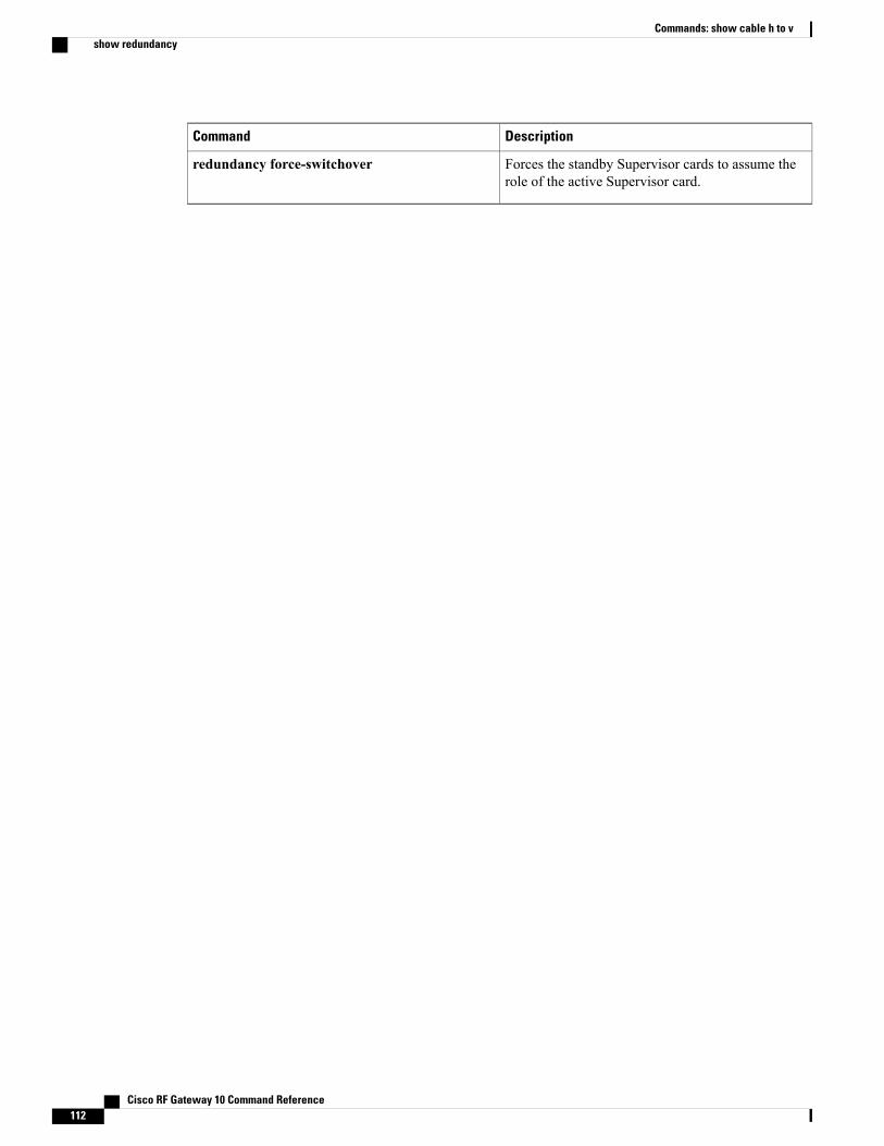
DescriptionCommand
Forces the standby Supervisor cards to assume therole of the active Supervisor card.
redundancy force-switchover
Cisco RF Gateway 10 Command Reference112
Commands: show cable h to vshow redundancy
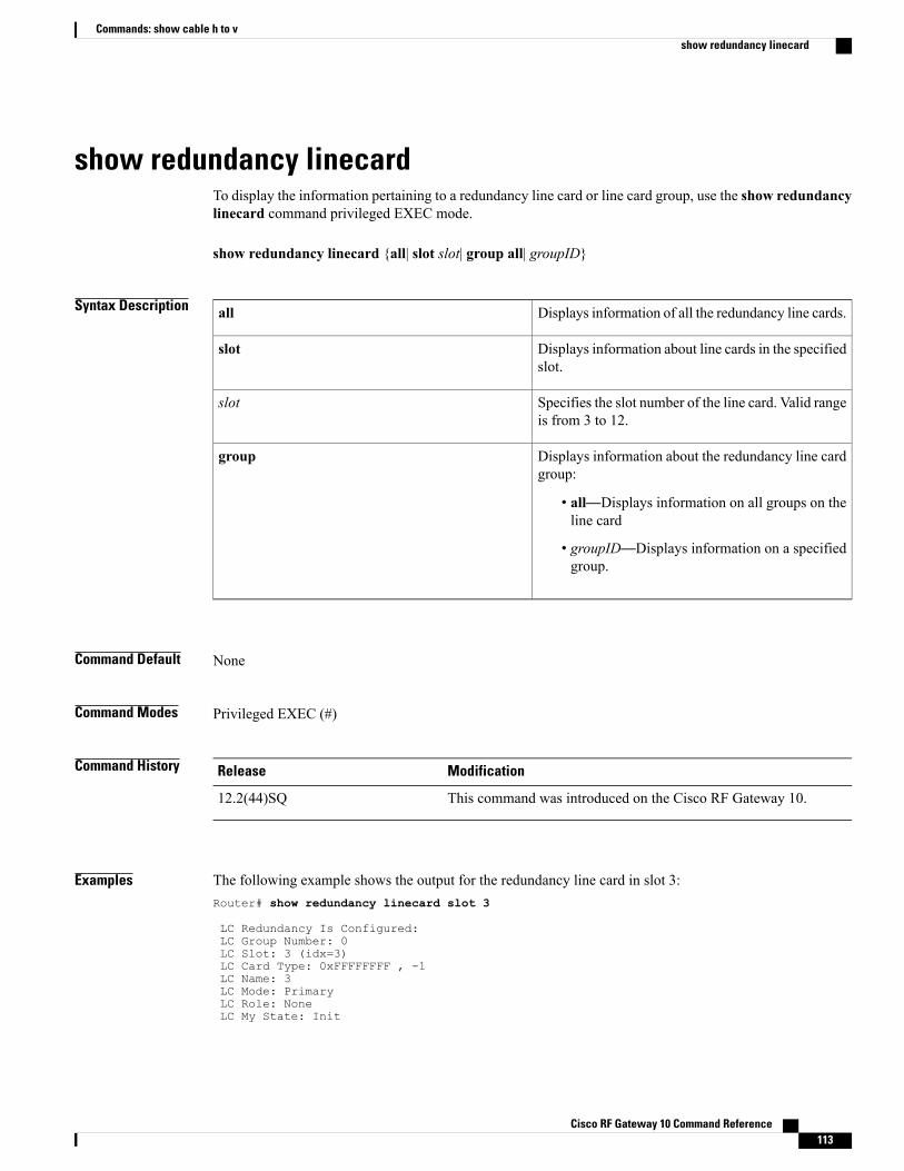
show redundancy linecardTo display the information pertaining to a redundancy line card or line card group, use the show redundancylinecard command privileged EXEC mode.
show redundancy linecard {all| slot slot| group all| groupID}
Syntax Description Displays information of all the redundancy line cards.all
Displays information about line cards in the specifiedslot.
slot
Specifies the slot number of the line card. Valid rangeis from 3 to 12.
slot
Displays information about the redundancy line cardgroup:
• all—Displays information on all groups on theline card
• groupID—Displays information on a specifiedgroup.
group
Command Default None
Command Modes Privileged EXEC (#)
Command History ModificationRelease
This command was introduced on the Cisco RF Gateway 10.12.2(44)SQ
Examples The following example shows the output for the redundancy line card in slot 3:Router# show redundancy linecard slot 3
LC Redundancy Is Configured:LC Group Number: 0LC Slot: 3 (idx=3)LC Card Type: 0xFFFFFFFF , -1LC Name: 3LC Mode: PrimaryLC Role: NoneLC My State: Init
Cisco RF Gateway 10 Command Reference 113
Commands: show cable h to vshow redundancy linecard
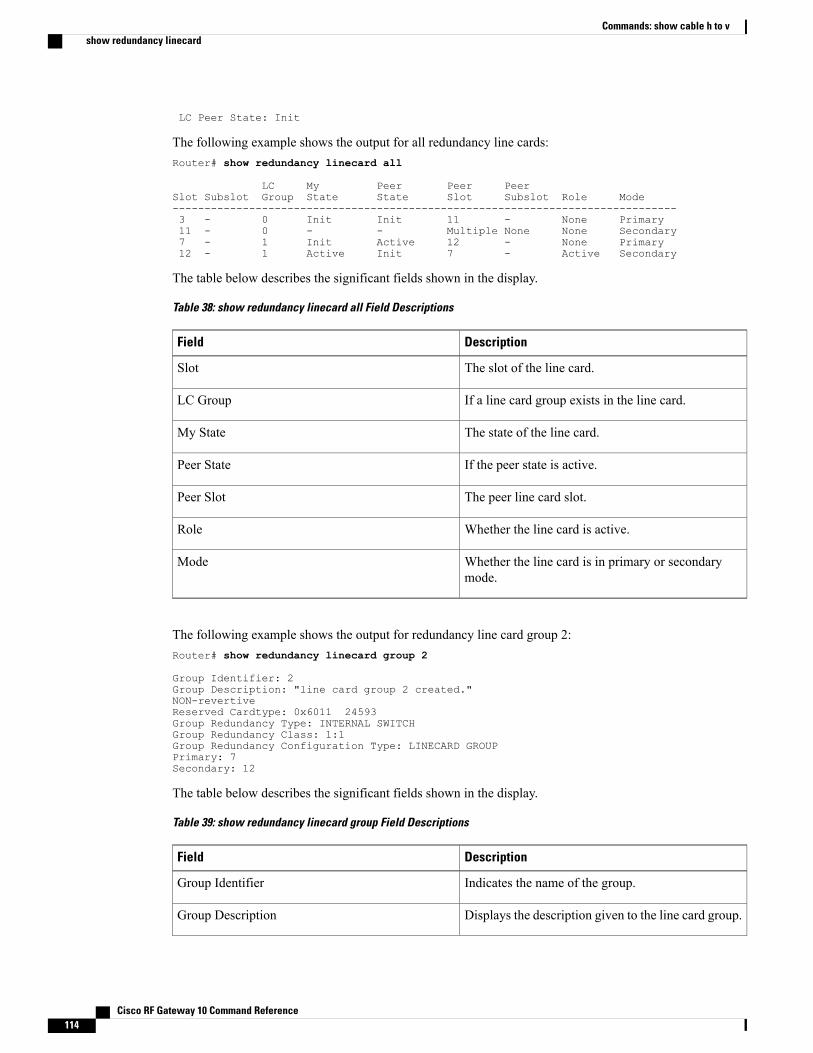
LC Peer State: Init
The following example shows the output for all redundancy line cards:Router# show redundancy linecard all
LC My Peer Peer PeerSlot Subslot Group State State Slot Subslot Role Mode-------------------------------------------------------------------------------3 - 0 Init Init 11 - None Primary11 - 0 - - Multiple None None Secondary7 - 1 Init Active 12 - None Primary12 - 1 Active Init 7 - Active Secondary
The table below describes the significant fields shown in the display.
Table 38: show redundancy linecard all Field Descriptions
DescriptionField
The slot of the line card.Slot
If a line card group exists in the line card.LC Group
The state of the line card.My State
If the peer state is active.Peer State
The peer line card slot.Peer Slot
Whether the line card is active.Role
Whether the line card is in primary or secondarymode.
Mode
The following example shows the output for redundancy line card group 2:Router# show redundancy linecard group 2
Group Identifier: 2Group Description: "line card group 2 created."NON-revertiveReserved Cardtype: 0x6011 24593Group Redundancy Type: INTERNAL SWITCHGroup Redundancy Class: 1:1Group Redundancy Configuration Type: LINECARD GROUPPrimary: 7Secondary: 12
The table below describes the significant fields shown in the display.
Table 39: show redundancy linecard group Field Descriptions
DescriptionField
Indicates the name of the group.Group Identifier
Displays the description given to the line card group.Group Description
Cisco RF Gateway 10 Command Reference114
Commands: show cable h to vshow redundancy linecard
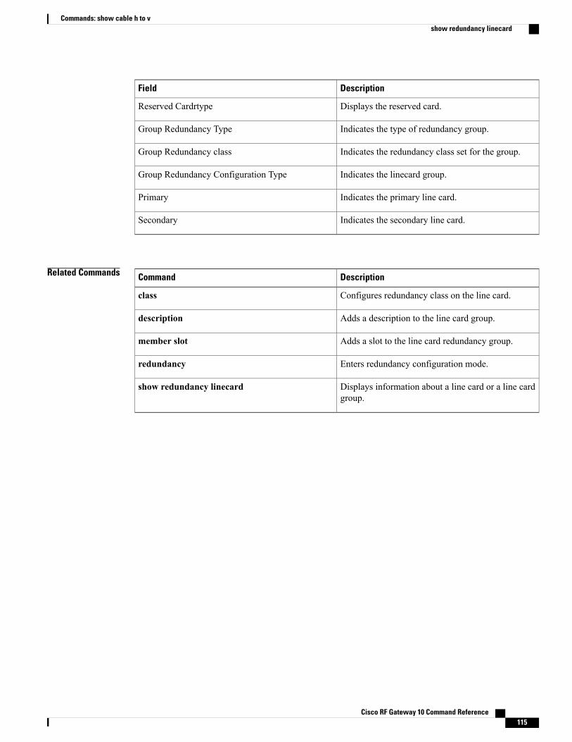
DescriptionField
Displays the reserved card.Reserved Cardrtype
Indicates the type of redundancy group.Group Redundancy Type
Indicates the redundancy class set for the group.Group Redundancy class
Indicates the linecard group.Group Redundancy Configuration Type
Indicates the primary line card.Primary
Indicates the secondary line card.Secondary
Related Commands DescriptionCommand
Configures redundancy class on the line card.class
Adds a description to the line card group.description
Adds a slot to the line card redundancy group.member slot
Enters redundancy configuration mode.redundancy
Displays information about a line card or a line cardgroup.
show redundancy linecard
Cisco RF Gateway 10 Command Reference 115
Commands: show cable h to vshow redundancy linecard
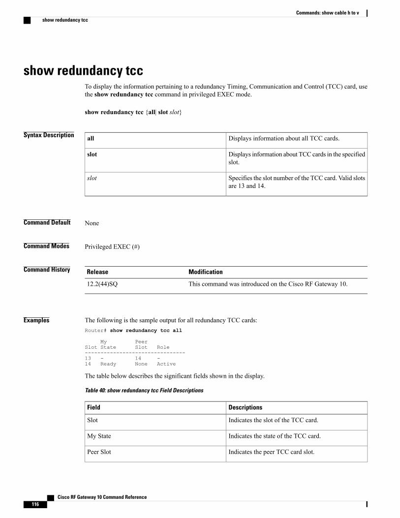
show redundancy tccTo display the information pertaining to a redundancy Timing, Communication and Control (TCC) card, usethe show redundancy tcc command in privileged EXEC mode.
show redundancy tcc {all| slot slot}
Syntax Description Displays information about all TCC cards.all
Displays information about TCC cards in the specifiedslot.
slot
Specifies the slot number of the TCC card. Valid slotsare 13 and 14.
slot
Command Default None
Command Modes Privileged EXEC (#)
Command History ModificationRelease
This command was introduced on the Cisco RF Gateway 10.12.2(44)SQ
Examples The following is the sample output for all redundancy TCC cards:Router# show redundancy tcc all
My PeerSlot State Slot Role--------------------------------13 - 14 -14 Ready None Active
The table below describes the significant fields shown in the display.
Table 40: show redundancy tcc Field Descriptions
DescriptionsField
Indicates the slot of the TCC card.Slot
Indicates the state of the TCC card.My State
Indicates the peer TCC card slot.Peer Slot
Cisco RF Gateway 10 Command Reference116
Commands: show cable h to vshow redundancy tcc

DescriptionsField
Indicates whether the TCC card is active.Role
Related Commands DescriptionCommand
Enters redundancy configuration mode.redundancy
Cisco RF Gateway 10 Command Reference 117
Commands: show cable h to vshow redundancy tcc
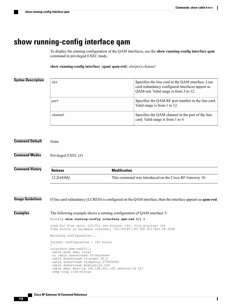
show running-config interface qamTo display the running configuration of the QAM interfaces, use the show running-config interface qamcommand in privileged EXEC mode.
show running-config interface {qam| qam-red} slot/port.channel
Syntax Description Specifies the line card in the QAM interface. Linecard redundancy configured interfaces appear asQAM-red. Valid range is from 3 to 12.
slot
Specifies the QAM RF port number in the line card.Valid range is from 1 to 12.
port
Specifies the QAM channel in the port of the linecard. Valid range is from 1 to 4.
channel
Command Default None
Command Modes Privileged EXEC (#)
Command History ModificationRelease
This command was introduced on the Cisco RF Gateway 10.12.2(44)SQ
Usage Guidelines If line card redundancy (LCRED) is configured on the QAM interface, then the interface appears as qam-red.
Examples The following example shows a running configuration of QAM interface 3:Router# show running-config interface qam-red 3/1.1
Load for five secs: 12%/0%; one minute: 14%; five minutes: 15%Time source is hardware calendar, *00:39:45.193 UTC Fri Nov 28 2008
Building configuration...
Current configuration : 263 bytes!interface Qam-red3/1.1cable mode depi localno cable downstream rf-shutdowncable downstream rf-power 50.0cable downstream frequency 279000000cable downstream modulation 256cable depi dest-ip 192.168.201.100 session-id 311snmp trap link-status
Cisco RF Gateway 10 Command Reference118
Commands: show cable h to vshow running-config interface qam
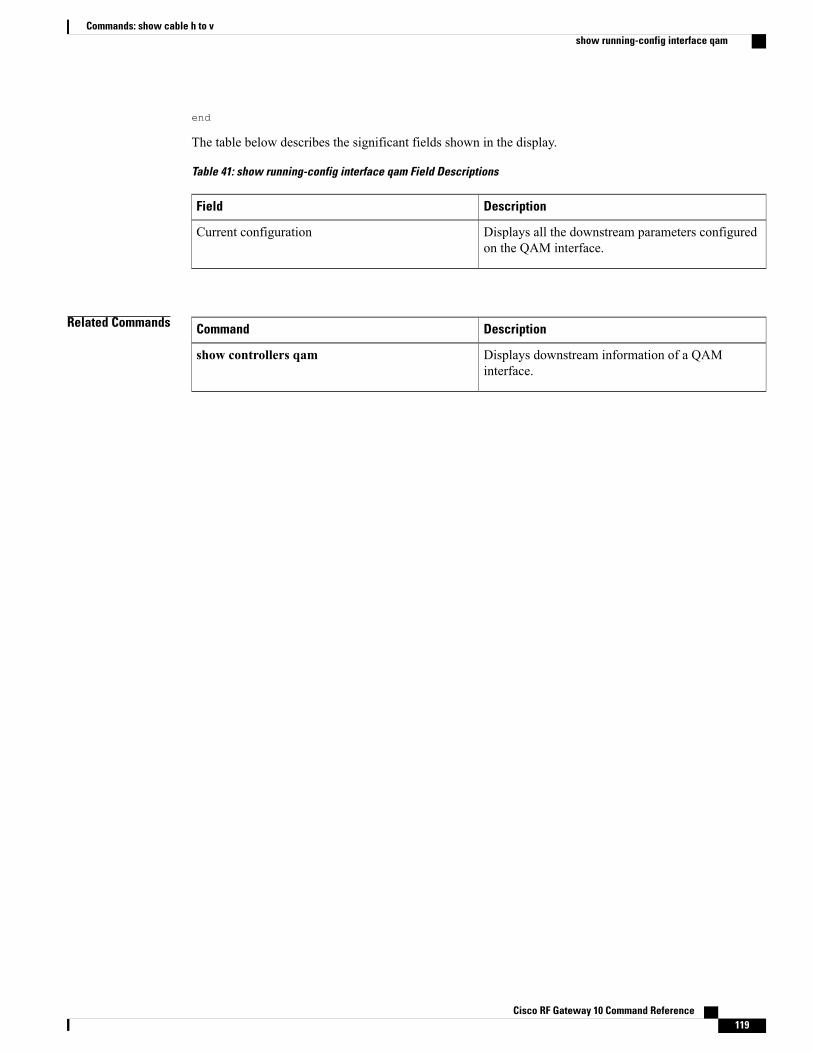
end
The table below describes the significant fields shown in the display.
Table 41: show running-config interface qam Field Descriptions
DescriptionField
Displays all the downstream parameters configuredon the QAM interface.
Current configuration
Related Commands DescriptionCommand
Displays downstream information of a QAMinterface.
show controllers qam
Cisco RF Gateway 10 Command Reference 119
Commands: show cable h to vshow running-config interface qam
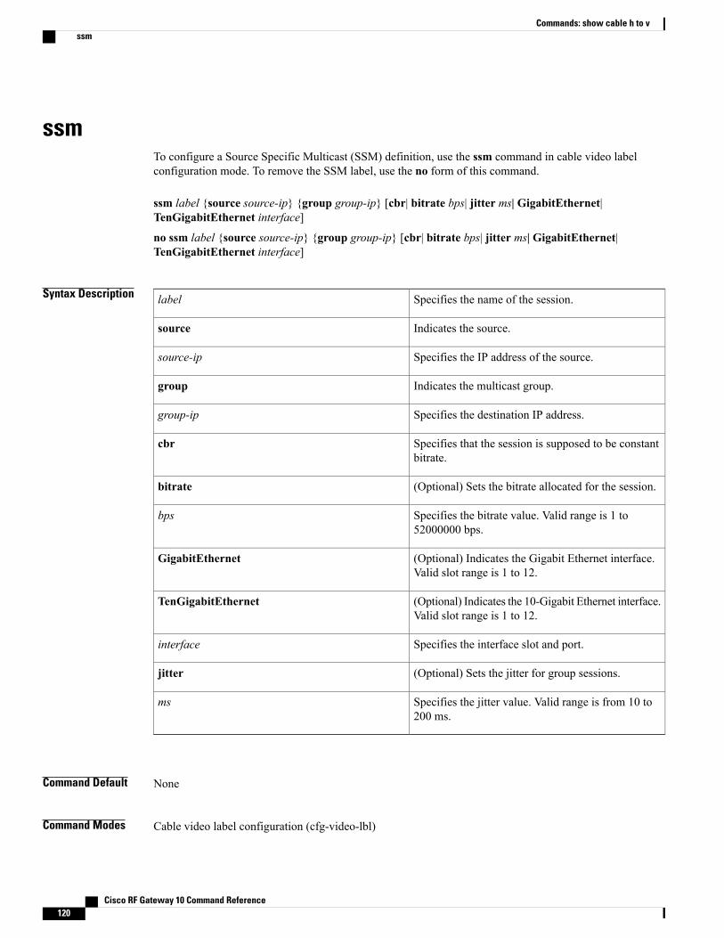
ssmTo configure a Source Specific Multicast (SSM) definition, use the ssm command in cable video labelconfiguration mode. To remove the SSM label, use the no form of this command.
ssm label {source source-ip} {group group-ip} [cbr| bitrate bps| jitter ms| GigabitEthernet|TenGigabitEthernet interface]
no ssm label {source source-ip} {group group-ip} [cbr| bitrate bps| jitter ms| GigabitEthernet|TenGigabitEthernet interface]
Syntax Description Specifies the name of the session.label
Indicates the source.source
Specifies the IP address of the source.source-ip
Indicates the multicast group.group
Specifies the destination IP address.group-ip
Specifies that the session is supposed to be constantbitrate.
cbr
(Optional) Sets the bitrate allocated for the session.bitrate
Specifies the bitrate value. Valid range is 1 to52000000 bps.
bps
(Optional) Indicates the Gigabit Ethernet interface.Valid slot range is 1 to 12.
GigabitEthernet
(Optional) Indicates the 10-Gigabit Ethernet interface.Valid slot range is 1 to 12.
TenGigabitEthernet
Specifies the interface slot and port.interface
(Optional) Sets the jitter for group sessions.jitter
Specifies the jitter value. Valid range is from 10 to200 ms.
ms
Command Default None
Command Modes Cable video label configuration (cfg-video-lbl)
Cisco RF Gateway 10 Command Reference120
Commands: show cable h to vssm

Command History ModificationRelease
This command was introduced on the Cisco RF Gateway 10.12.2(44)SQ
This command is modified. The bitrate keyword is made optional.Cisco IOS-XE Release 3.3.1SQ
Usage Guidelines Cisco RF Gateway 10 supports Source Specific Multicast (SSM) video sessions. An SSM video label isidentified by the source and group IP address pair. You can specify upto three source addresses for each SSMvideo label. This can be achieved by reusing the same video label for all the source addresses. The addresspairs under the same label must have different source IP addresses. The Cisco RFGW-10 cycles the addresspairs to look for an active source.
These address pairs are redundant sources for the label. Address pairs under the same label must have identicalsettings for cbr, bitrate, and jitter. If additional address pairs are entered without these parameters, thecorresponding values for the first address pair are used. These parameters can be modified by re-entering thefirst address pair with new parameter settings. The change is propagated to all the address pairs under thesame label.
An SSM video session can be mapped to multiple QAM channels. All cloned sessions of the same video labelshare the same attributes.
The label definition cannot be modified once the label is used in a QAM channel. Address pairs cannotbe added or deleted, or any optional parameters cannot be modified. Effective with Cisco IOS-XE Release3.3.0SQ and later releases, the label definitions can be modified. The optional parameters like bitrate andjitter cannot be modified. You can also add or delete backup sources. However, an active source cannotbe deleted.
Note
To avoid oversubscription, ensure that the actual bitrate of the video session does not exceed the allocatedbitrate.
Note
Examples The following example shows the SSM configuration on the Cisco RF Gateway 10:Router# configure terminalRouter(config)# cable video labelsRouter(cfg-video-lbl)# ssm ssm1 source 10.1.1.1 group 233.1.1.1 bitrate 3750000Router(cfg-video-lbl)# exit
The following example shows how to configure a backup source:Router# configure terminalRouter(config)# cable video labelsRouter(cfg-video-lbl)# ssm ssm1 source 10.2.2.2 group 233.1.1.1 bitrate 3750000Router(cfg-video-lbl)# ssm ssm1 source 10.3.3.3 group 233.1.1.1 bitrate 3750000Router(cfg-video-lbl)# exit
Cisco RF Gateway 10 Command Reference 121
Commands: show cable h to vssm
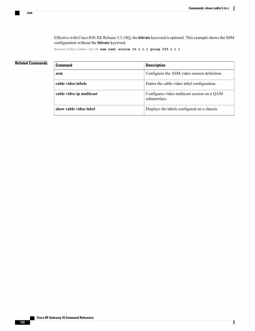
Effective with Cisco IOS-XE Release 3.3.1SQ, the bitrate keyword is optional. This example shows the SSMconfiguration without the bitrate keyword.Router(cfg-video-lbl)# ssm ssm1 source 10.1.1.1 group 233.1.1.1
Related Commands DescriptionCommand
Configures the ASM video session definition.asm
Enters the cable video label configuration.cable video labels
Configures video multicast session on a QAMsubinterface.
cable video ip multicast
Displays the labels configured on a chassis.show cable video label
Cisco RF Gateway 10 Command Reference122
Commands: show cable h to vssm
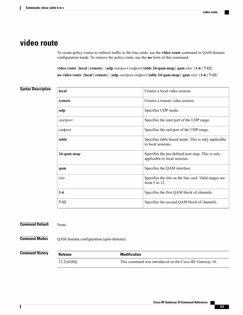
video routeTo create policy routes to redirect traffic to the line cards, use the video route command in QAM domainconfiguration mode. To remove the policy route, use the no form of this command.
video route {local | remote} {udp startport endport| table 24-qam-map} qam slot/ {1-6 | 7-12}
no video route {local | remote} {udp startport endport| table 24-qam-map} qam slot/ {1-6 | 7-12}
Syntax Description Creates a local video session.local
Creates a remote video session.remote
Specifies UDP mode.udp
Specifies the start port of the UDP range.startport
Specifies the end port of the UDP range.endport
Specifies table-based mode. This is only applicableto local sessions.
table
Specifies the pre-defined port map. This is onlyapplicable to local sessions.
24-qam-map
Specifies the QAM interface.qam
Specifies the slot on the line card. Valid ranges arefrom 3 to 12.
slot
Specifies the first QAM block of channels.1-6
Specifies the second QAM block of channels.7-12
Command Default None
Command Modes QAM domain configuration (qam-domain)
Command History ModificationRelease
This command was introduced on the Cisco RF Gateway 10.12.2(44)SQ
Cisco RF Gateway 10 Command Reference 123
Commands: show cable h to vvideo route
Usage Guidelines Video routes are used to direct traffic to the underlying QAMblocks in a QAMdomain. A video route specifiesa continous range of UDP ports mapped to a QAM block. For a local route, the UDP ports are taken from thelocal IP address. For a remote route, the UDP ports are taken from the remote IP address. A pre-defined UDPmap also is present for local video routes, where the UDP ports are defined by a map.
Policy routes are used to redirect traffic to line cards. QAM blocks are added to QAM domains using videopolicy routes. Each video policy route specifies a range of QAM channels. QAM channels are bound to aQAM block in the video route.
In a local configuration, you can configure the QAM channels using the CLI, GUI or SNMP.
In a remote configuration, the video control plane configures the QAM channels using GQI.
The local session offers two methods of mapping UDP ports to QAM ports:
• User- specified UDP ranges: Start and end UDP ports are specified in the CLI. The video route maps arange of UDP destination ports from the local IP address to the QAM block.
• Table-based: referred to as 24-qam-map. This is a pre-defined range with a default UDP port range of49152 to 55295. The video route uses the UDP port map defined in the table for the QAM block.
Only one QAM map is used per QAM domain.Note
In the remote session, only user-specified UDP range setup is allowed. Data network Control Station (DNCS)and Universal Session and Resource Manager (USRM) controls the session setup.
No two video routes within a QAM domain can overlap in IP address and UDP range.Note
Removing a video route results in removal of all the sessions configured with that video route.Note
Examples The following example shows a video route for a local session on QAM domain 5:Router# configure terminalRouter(config)# cable qam-domain 5Router(qam-domain)# ip 1.1.1.1 localRouter(qam-domain)# video route local udp 50000 51000 qam 7/1-6Router(qam-domain)# video route local udp 51001 52000 qam 7/7-12Router(qam-domain)# exitRouter(config)# exit
The following example shows a video route for a remote session on QAM domain 5:Router# configure terminalRouter(config)# cable qam-domain 5Router(qam-domain)# ip 1.1.1.1 remoteRouter(qam-domain)# video route remote udp 20000 21000 qam 7/1-6Router(qam-domain)# video route remote udp 21001 22000 qam 7/7-12Router(qam-domain)# exitRouter(config)# exit
Cisco RF Gateway 10 Command Reference124
Commands: show cable h to vvideo route
The following example shows a table-based policy route on QAM domain 5:Router# configure terminalRouter(config)# cable qam-domain 5Router(qam-domain)# ip 1.1.1.1 localRouter(qam-domain)# video route local table 24-qam-map qam 3/1-6Router(qam-domain)# exit
The following example shows non-overlapping UDP ranges and QAM channel lists:Router(qam-domain)# video route local udp 50001 51000 qam 3/1-6Router(qam-domain)# video route local udp 51001 52000 qam 3/7-12Router(qam-domain)# video route local udp 52001 53000 qam 5/1-6
Related Commands DescriptionCommand
Enters QAM domain configuration mode.cable qam-domain
Configures the IP address for video and remotesessions.
ip
Cisco RF Gateway 10 Command Reference 125
Commands: show cable h to vvideo route

Cisco RF Gateway 10 Command Reference126
Commands: show cable h to vvideo route