commander 250 user guide universal process controller pdfs/c250 im.pdf · commander 250 universal...
TRANSCRIPT

COMMANDER 250Universal Process Controller
User Guide
COMMANDER 250
47.5
50.0OP1
OP2
°C
°F
A1 A2 R M

Note.Clarification of an instruction oradditional information.
Information.Further reference for more detailedinformation or technical details.
Use of Instructions
Although Warning hazards are related to personal injury, and Caution hazards areassociated with equipment or property damage, it must be understood that operation ofdamaged equipment could, under certain operational conditions, result in degradedprocess system performance leading to personal injury or death. Therefore, comply fullywith all Warning and Caution notices.
Information in this manual is intended only to assist our customers in the efficient operationof our equipment. Use of this manual for any other purpose is specifically prohibited andits contents are not to be reproduced in full or part without prior approval of TechnicalCommunications Department, ABB Ltd.
Health and SafetyTo ensure that our products are safe and without risk to health, the following pointsmust be noted:
1. The relevant sections of these instructions must be read carefully beforeproceeding.
2. Warning labels on containers and packages must be observed.
3. Installation, operation, maintenance and servicing must only be carried out bysuitably trained personnel and in accordance with the information given.
4. Normal safety precautions must be taken to avoid the possibility of an accidentoccurring when operating in conditions of high pressure and/or temperature.
5. Chemicals must be stored away from heat, protected from temperature extremesand powders kept dry. Normal safe handling procedures must be used.
6. When disposing of chemicals ensure that no two chemicals are mixed.
Safety advice concerning the use of the equipment described in this manual or anyrelevant hazard data sheets (where applicable) may be obtained from the Companyaddress on the back cover, together with servicing and spares information.
Warning.An instruction that draws attention tothe risk of injury or death.
Caution.An instruction that draws attention tothe risk of damage to the product,process or surroundings.

1
Symbol Identification and Section Contents
GETTING STARTED
This manual is divided into 5 sections which contain all the information needed toinstall, configure, commission and operate the COMMANDER 250. Each section isidentified clearly by a symbol as shown below.
Displays and Function Keys• Displays and function keys• LED Indication• Error Messages
Operator Mode (Level 1)• Operator menus for:
– Standard controller– Heat/Cool controller– Remote Set Point controller– Profile controller– Multiple Fixed Set Points controller
• Auto tuning
Set Up Mode (Levels 2, 3 and 4)• Level 2 – Tuning• Level 3 – Set Points• Level 4 – Profile
Configuration Mode (Levels 5 and 6)• Level 5 – Basic hardware and control
functions• Level 6 – Ranges and passwords
Installation• Siting• Mounting• Electrical connections
8

2
CONTENTS
Information.The fold-out page inside on the back cover of thismanual shows all the frames in the programminglevels. Space is provided on the page for writing theprogrammed setting or selection for each frame.
1 DISPLAYS AND FUNCTION KEYS ............................................................. 31.1 Introduction .......................................................................................... 31.2 LED Alarms and Indicators ................................................................. 41.3 Use of Function Keys .......................................................................... 61.4 Error Messages ................................................................................... 7
2 OPERATOR MODE ...................................................................................... 82.1 Introduction .......................................................................................... 82.2 Standard Controller ............................................................................. 92.3 Heat/Cool Controller .......................................................................... 102.4 Remote Set Point Controller ............................................................. 122.5 Profile Controller ............................................................................... 142.6 Multiple Fixed Set Points Controller ................................................. 162.7 Auto-tune ........................................................................................... 18
3 SET UP MODE ............................................................................................ 203.1 Introduction ........................................................................................ 203.2 Tuning (Level 2) ................................................................................ 203.3 Set Points (Level 3) ........................................................................... 243.4 Profile (Level 4) ................................................................................. 27
4 CONFIGURATION MODE .......................................................................... 304.1 Introduction .................................................................................... 304.2 Accessing the Configuration Mode ................................................... 304.3 Basic Hardware and Configuration (Level 5) ................................... 324.4 Ranges and Passwords (Level 6) ................................................. 42
5 INSTALLATION .......................................................................................... 465.1 Siting .................................................................................................. 465.2 Mounting ............................................................................................ 485.3 Removing the Instrument from the Case .......................................... 505.4 Electrical Connections ...................................................................... 515.5 Relays, Arc Suppression and Outputs ............................................. 51

3
1 DISPLAYS AND FUNCTION KEYS
Fig. 1.1 Front Panel Displays, Function Keys and Indicators
1.1 Introduction – Fig. 1.1The COMMANDER 250 front panel displays, function keys and l.e.d. indicators areshown in Fig. 1.1.
Alarm LEDs
Upper Display
Remote Set PointLED
Output ValueLEDs(secret-til-lit) Manual Control
LED
COMMANDER 250
A1 A2 R M
OP1
OP2
°C
°F
Function Keys
Raise
Lower
Auto/Manual
Parameter Advance
LowerDisplay
Units ofmeasureindication(secret-til-lit)8888
8888

4
…1 DISPLAYS AND FUNCTION KEYS
Fig. 1.2 LED Alarms and Indicators
1.2 LED Alarms and Indicators – Figs. 1.2 and 1.3
LED Status
All • All LEDs flashing – controller is in the configuration mode.
A1 • Flashes when Alarm 1 is active (off when inactive).
A2 • Flashes when Alarm 2 is active (off when inactive).
R • On when the controller is operating on the remote set point value.
• Off when the controller is operating using the local set pointvalue or one of the four fixed set points (in multiple set point mode).
• Flashes when a Ramp/Soak profile is running.
M • On when the controller is operating in Manual control mode.
• Off when the controller is operating in Auto control mode.
• Flashes when the controller is performing an auto-tune.
A1
R
M
COMMANDER 250
A1 A2 R M
OP1
OP2
°C
°F88888888
A2

5
Fig. 1.3 Secret-til-lit Indicators
1 DISPLAYS AND FUNCTION KEYS…
…1.2 LED Alarms and Indicators – Figs. 1.2 and 1.3
LED Status
OPI • LED indicates when the output 1 (heat) value is displayedin the lower display.
OP2 • LED indicates when the output 2 (cool) value is displayedin the lower display.
°C • LED indicates when the controller is configured to measurein degrees Celsius.
°F • LED indicates when the controller is configured to measure
in degrees Fahrenheit.
Output 1 LED(secret-til-lit)
COMMANDER 250
A1 A2 R M
OP1
OP2
°C
°F
°C units of measure(secret-til-lit)
°F units of measure(secret-til-lit)
88888888Output 2 LED
(secret-til-lit)

6
…1 DISPLAYS AND FUNCTION KEYS
1.3 Use of Function Keys – Fig. 1.4
Fig. 1.4 Use of Function Keys
A – Raise and Lower Keys
LEV1OPEr
LEV2tUnE
B – Parameter Advance Key
LEV2tUnE
CYCl 5.0
Frame 2
bIAS 50.0 51.0
49.0
+
–
C – Auto/Manual Key
Use to change/set a parameter value… …move between levelsand…
125.2 70
125.2125.8
M
Auto
M
ManualIlluminated
Control Output (%)
Process Variable
Control Set Point
Process Variable
Use to select Auto or Manual control mode
Frame 1(top of level)
Use to advance to the next framewithin a level…
Press and hold
…select the top (LEVEL) framefrom within a level
Note. This key also stores any changes made in the previous frame
LEVx100110021003
and…

7
Display Error/Action
Calibration errorTurn mains power off and on again(if the error persists contact theService Organization).
Configuration errorThe configuration and/or setup datafor the instrument is corrupted.Turn mains power off and on again(if the error persists, checkconfiguration/setup settings).
A to D Converter FaultThe analog to digital converter isnot communicating correctly.
Process Variable Over/UnderRange
Remote Set Point Over/UnderRangeThe remote set point value is overor under range. Flashing stopsautomatically when the remote setpoint input comes back into range.
Option errorCommunications to the optionboard have failed.
Auto-tune errorThe number displayed indicates thetype of error present – see Table 2.1in Section 2.7.
To Clear Display
Press the key
Press the key
Turn mains power off& on again, if the errorpersists contact theService Organization
Restore valid input
Select the local setpoint (rSP.n) inthe Operating Pageor the Set PointsLevel
Contact the ServiceOrganization
Press any key
1 DISPLAYS AND FUNCTION KEYS…
1.4 Error Messages
CALErr
CnFGErr
A-dErr
OPtnErr
t.Err 1
9999 70
125.2 70

8
2 OPERATOR MODE
2.1 IntroductionOperator Mode (Level 1) is the normal day-to-day mode of the COMMANDER 250.
Frames displayed in level 1 are determined by the control strategy which isselected during configuration of the instrument – see Section 4.
Note. Only the operating frames relevant to the configured strategy aredisplayed in Operator Mode.
The five control strategies are:
• Standard controller – page 9
• Heat/Cool controller – page 10
• Remote Set Point controller – page 12
• Profile controller – page 14
• Multiple Fixed Set Points controller – page 16

9
2.2 Standard Controller
2 OPERATOR MODE…
•1 Not displayed if the ramping set point facility is turned off – refer toSection 3.3.
Man
Auto
70
SPrP120.5
CodE 0
OP1
125.2125.8
125.2
AtnE OFF
OPEr LEV4PrFL
LEV1
LEV3SEtPtUnE
LEV2
•1
Process Variable Value
Control Set Point Value (Local set point)[Set point low limit to set point high limit]
Process Variable Value
Control Output Value (%)[0 to 100% (–10% to 110% for analog output)]Adjustable in manual mode only.
Ramping Set Point Value (Read only)The actual set point value is displayed i.e. theinstantaneous value the controller is working to.
Security Code[0 to 9999]Select the appropriate security code to access:
Auto-tune enable frame (Level 1),Set Up mode (Levels 2, 3, 4).
Auto-tune EnableON – Auto-tune onOFF – Auto-tune off
Refer to page 16 for the Auto-tune procedure.
Level 1 (Operator mode)Refer to Section 3 for levels 2, 3 and 4.

10
2.3 Heat/Cool Controller
…2 OPERATOR MODE
•1 Not displayed if the ramping set point facility is turned off – refer toSection 3.3.
Man
SPrP
Auto
70
120.5
OP1 (Heat)
125.2125.8
125.2
-30OP2 (Cool)
125.2
•1
CodE 0
Process Variable Value
Control Set Point Value (Local set point)[Set point low limit to set point high limit]
Process Variable Value
Control Output Value (Heat %)[0% to 100% (0% to 110% for analog output)]If adjusted below 0% the 'Cool' frame is displayed.
Control Output 2 Value (Cool %)[0% to –100% (0% to –110% for analog output)]If adjusted above 0% the 'Heat' frame is displayed.
Ramping Set Point Value (Read only)The actual set point value is displayed i.e. theinstantaneous value the controller is working to.
Continued on next page.

11
2 OPERATOR MODE…
…2.3 Heat/Cool Controller
CodE 0
AtnE OFF
OPEr LEV4PrFL
LEV1
LEV3SEtPtUnE
LEV2
Security Code[0 to 9999]Select the appropriate security code to access:
Auto-tune enable frame (Level 1),Set Up mode (Levels 2, 3, 4).
Auto-tune EnableON – Auto-tune onOFF – Auto-tune off
Refer to page 16 for the Auto-tune procedure.
Level 1 (Operator mode)See Section 3 for levels 2, 3 and 4.

12
2.4 Remote Set Point Controller
…2 OPERATOR MODE
Note.If the remote set point input fails while selected, the controller selects the localset point value automatically. The upper display changes to rSP.F and thelower display flashes. When the fault condition is removed the remote set pointis re-selected automatically. To clear the error condition while the remote setpoint input is still outside its allowed range, select the local set point by pressingthe key (rSP.n is displayed).
Process Variable Value
Control Set Point Value[Set point low to set point high limit]Adjustable in local Set Point Mode only.
Process Variable Value
Control Output Value (%)[0% to 100% (–10% to 110% for analog output)]Adjustable in manual mode only.
Remote Set Point SelectionrSPY – Remote Set PointrSPn – Local Set Point
Local or remote set point can also be selected usinga digital input.
The option to change the set point selection at thisframe can be disabled in the configuration level.
Remote Set Point Value (read only)
Continued on next page…
Man
Auto
rSPn
70OP1
125.2125.8
125.2
123.4rSPn123.4
SPrP120.5

13
2 OPERATOR MODE…
…2.4 Remote Set Point Controller
•1 Not displayed if the ramping set point facility is turned off – refer toSection 3.3.
CodE 0
SPrP120.5
•1
AtnE OFF
OPEr LEV4PrFL
LEV1
LEV3SEtPtUnE
LEV2
Ramping Set Point Value (Read only)The actual set point value is displayed i.e. theinstantaneous value the controller is working to.
Security Code[0 to 9999]Select the appropriate security code to access:
Auto-tune enable frame (Level 1),Set Up mode (Levels 2, 3, 4).
Auto-tune EnableON – Auto-tune onOFF – Auto-tune off
Refer to page 16 for the Auto-tune procedure.
Level 1 (Operator mode)See Section 3 for levels 2, 3 and 4.

14
…2 OPERATOR MODE
2.5 Profile Controller
Process Variable Value
Control Set Point Value[Set point low limit to set point high limit]
Process Variable Value
Control Output Value (%)[0% to 100% (–10% to 110% for analog output)]Adjustable in manual mode only.
Profile Segment Number (1 to 4) currently active
Profile Status
StOP – Profile inactive – the control set pointis equal to the local set point valuewhen the profile is not running.
run – Profile active – currently operating onthe segment indicated.
HOLD – Profile hold – pauses the current rampor soak mode by putting it into 'Hold'mode. The guaranteed ramp soakfeature can also be used to put the profileinto a 'Hold' mode until the processvariable comes back within thehysteresis band.
Note. The profile status can be changed usinga digital input.
Continued on next page…
Man
Auto
70OP1
125.2125.8
125.2
StoPSG 1
120.5SPrP
SG 1HOLd
SG 1StoP
SG 1 run

15
…2.5 Profile Controller
2 OPERATOR MODE…
•1 Not displayed if the ramping set point facility is turned off – refer toSection 3.3.
CodE 0
SPrP120.5
•1
AtnE OFF
OPEr LEV4PrFL
LEV1
LEV3SEtPtUnE
LEV2
Ramping Set Point Value (Read only)The actual set point value is displayed i.e. theinstantaneous value the controller is working to.
Security Code[0 to 9999]Select the appropriate security code to access:
Auto-tune enable frame (Level 1),Set Up mode (Levels 2, 3, 4).
Auto-tune EnableON – Auto-tune onOFF – Auto-tune off
Refer to page 16 for the Auto-tune procedure.
Level 1 (Operator mode)See Section 3 for levels 2, 3 and 4.

16
…2 OPERATOR MODE
2.6 Multiple Fixed Set Points ControllerIf the Multiple Fixed Set Points Controller type is selected during configuration, fourfixed control set points can be set – see Section 4.4.
•1 Not displayed if the ramping set point facility is turned off – refer toSection 3.3.
Man
•1
Auto
70
0
OP1
125.2125.8
125.2
12.05SPrP
CodE
SP-1100.3
SP-4400.5
SP-2200.1
SP-3300.2
Process Variable Value
Fixed Control Set Point Selected
Notes.a) The top display momentarily displays the set
point selected before reverting to the displayof the process variable value.
b) A digital input can also be used to select thefixed set points.
Process Variable Value
Control Output Value (%)[0% to 100% (–10% to 110% for analog output)]Adjustable in manual mode only.
Ramping Set Point Value (Read only)The actual set point value is displayed i.e. theinstantaneous value the controller is working to.
Continued on next page…

17
2 OPERATOR MODE…
…2.6 Multiple Fixed Set Points Controller
CodE 0
AtnE OFF
LEV4PrFL
LEV1
LEV3SEtPtUnE
LEV2OPEr
Security Code[0 to 9999]Select the appropriate security code to access:
Auto-tune enable frame (Level 1),Set Up Mode (Levels 2, 3, 4).
Auto-tune EnableON – Auto-tune onOFF – Auto-tune off
Refer to page 16 for the Auto-tune procedure.
Level 1 (Operator mode)See Section 3 for Levels 2, 3 and 4.

18
…2 OPERATOR MODE
2.7 Auto-tune
Information.• Auto-tune optimizes process control by monitoring process performance
and automatically updates the control parameters.
• Before starting auto-tune, the process variable must be stable (±2% ofengineering range).
Fig 2.1 Typical Auto-tune Cycles
Note. The timetaken to completeautotune dependsupon the systemresponse time.
t1b – Process response during auto-tune
+2%
- 2%
+2%- 2%
t t1a – Stable process before auto-tune
1 – 'Start up' auto-tune (from manual mode)
2 – 'At set point' auto-tune (from manual or automatic mode)
SP SP
PV
PVSP
PV
Typical process response after auto-tunet
PV
1/4 wavedamping
SP
t
PV1/4 wavedamping
SP
Controlling toSet Point
Auto-tunecomplete
Auto-tunecomplete
Controllingto Set Point
2a – Stable process before auto-tune
2b – Process response during auto-tune

19
2 OPERATOR MODE
…2.7 Auto-tuneFrom Security Code frame (any Operating page)The correct password must be entered to access theauto-tune frame.
Auto-tune EnableON – Auto-tune onOFF – Auto-tune off
Auto-tune can be stopped at any time by pressing the key.
Settings for P + I control onlyTo tune for P + I control only, set the derivative termto 'OFF' in the Tuning Level – see Section 3.2.
Notes.• On completion the controller enters auto control mode and begins to control
the process using the new PID values. For fine-tuning – see Section 3.
• For heat/cool control the cool proportional band is set to the same value asthe heat proportional band (this value may need modification).
• If an error occurs during auto-tune, the controller reverts to manual modewith the control output set to the configured output value. An error messageis displayed – see Table 2.1.
Table 2.1 Auto-tune Error Codes
Error Description
1 PV failed during auto-tune2 Auto-tune has timed out during an auto-
tune step3 Process too noisy to auto-tune4 Process too fast to auto-tune5 Process too slow to auto-tune6 PV deviated from set point by >25% eng.
span during frequency response test
Error Description
7 A resultant P, I or D value was calculatedout of range
8 PV limit exceeded (At start up auto-tune)9 Controller put into configuration mode
10 Auto-tune terminated by user11 PV is changing in the wrong direction
during step test
AtnE OFF
OPEr LEV4PrFL
LEV1
LEV3SEtPtUnE
LEV2
CodE x
20
3 SET UP MODE
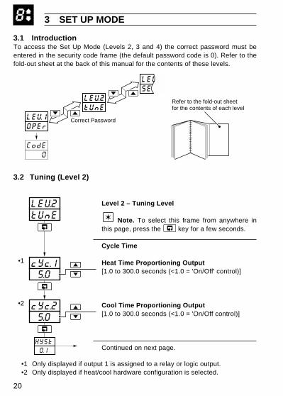
3.1 IntroductionTo access the Set Up Mode (Levels 2, 3 and 4) the correct password must beentered in the security code frame (the default password code is 0). Refer to thefold-out sheet at the back of this manual for the contents of these levels.
3.2 Tuning (Level 2)
Level 2 – Tuning Level
Note. To select this frame from anywhere inthis page, press the key for a few seconds.
Cycle Time
Heat Time Proportioning Output[1.0 to 300.0 seconds (<1.0 = 'On/Off' control)]
Cool Time Proportioning Output[1.0 to 300.0 seconds (<1.0 = 'On/Off control)]
Continued on next page.
•1 Only displayed if output 1 is assigned to a relay or logic output.•2 Only displayed if heat/cool hardware configuration is selected.
8
LEV1OPEr
CodE 0
LEV2tUnE
Correct Password
SEtPLEV3
Refer to the fold-out sheetfor the contents of each level
5.0cYc.2
cYc.1 5.0
LEV2tUnE
0.1
•1
•2
HYSt

21
…3 SET UP MODE
…3.2 Tuning (Level 2) – Fig. 3.2
On/Off Hysteresis Value(used for both heat and cool outputs)[In engineering units]
Proportional BandEnter the proportional band value for the heat andcool outputs.
Heat Output (Output 1)[0.1% to 999.9%]
Cool Output (Output 2)[0.1% to 999.9%]
Continued on next page.
•1 Only displayed if On/Off control is selected for either output.•2 Only displayed if heat/cool hardware configuration is selected.
8
100.0Pb-H
100.0Pb-c
30Intr
0.1HYSt•1
Set Point
Reverse ActingControl Output
PV
OFF
ON
Hysteresis Value
•2

22
…3 SET UP MODE
…3.2 Tuning (Level 2)
•1 Only displayed if a heat/cool hardware configuration is selected.
8
1.0dr1U
50rSEt
0.00.LAP•1
30Intr Integral Action Time
[1 to 7200 seconds or OFF (OFF=0)]
Manual Reset Value[0% to 100% or –100% to +100% for heat/cool]This value is applied as a bias to the control output.
Note. Manual reset is applied with integralaction both on and off.
Derivative Action Time[0.1 to 999.9 seconds or OFF (OFF=0)]
Overlap for Heat/Cool Control[–20.0% to +20.0%]This frame defines the portion of the proportionalband (Proportional band heat + Proportional bandcool) over which both outputs are active – see Fig.3.1. Neither output is active in the deadband.
A positive value gives an overlap and a negativevalue a deadband.

23
3 SET UP MODE…
Fig. 3.1 Proportional Band & Deadband/Overlap – Heat/Cool Control Only
8
a) Overlap
Output 1(heat)
Output 2(cool)O
utpu
t Pow
er (
%)
Output 2 (cool)
Output 1 (heat)
Proportional Band (Heat)
Pb-h
Process Variable
Overlap (positive value)
b) Deadband
Output 1
Output 2
Out
put P
ower
(%
)
Output 2
Output 1
Proportional Band Heat
Process Variable
Deadband (negative value)
Proportional Band Cool
c) Output 2 on/off control
Output 1
Output 2Out
put P
ower
(%
)
Output 2
Output 1
Process Variable
ON/OFF' Hysteresis (0% overlap)
O/P
2 O
FF
O/P
2 O
N
Positive values Negative values
Overlap/Deadband
Pb-c
OLAP
Pb-h Pb-c
Proportional Band (Cool)
OLAP
Proportional Band Heat
Pb-h
HYSt
OLAP

24
…3 SET UP MODE
3.3 Set Points (Level 3)
Level 3 – Set Points Level
Note. To select this frame from anywhere inthis page, press the key for a few seconds.
Local Set Point Value[Within set point high and low limits, in engineeringunits]
Remote Set Point SelectionSet Point Type:
rSP.Y – remote set pointrSP.n – local set point
Remote set point value.
Alarm 1 Trip PointAlarm type:
A1.hP = High process alarmA1.LP = Low process alarmA1.hd = High deviation alarmA1.Ld = Low deviation alarmA1.Lb = Loop break alarm
Trip Point:Process & deviation alarms [in engineering units]Loop break alarm [1 to 9999 seconds]
Continued on next page.
•1 Only displayed if the remote set point option is selected.
8
145.8rSP.n
LSPt125.8
800.0A1.hP
LEV3SEtP
270.0
•1
A1.HY

25
1.000rAt0
0.0bIAS
200.0A2.hP
r.rtE OFF
•2
•2
162.0A1.HY•1
18.5A2.HY•1
3 SET UP MODE…
Alarm 1 Hysteresis Value[in engineering units]
Alarm 2 Trip PointAlarm type:
A2.hP = High process alarmA2.LP = Low process alarmA2.hd = High deviation alarmA2.Ld = Low deviation alarmA2.Lb = Loop break alarm
Trip Point:Process & deviation alarms [in engineering units]Loop break alarm [1 to 9999 seconds]
Alarm 2 Hysteresis Value[in engineering units]
Remote Set Point Input Ratio and BiasThe remote set point value =
ratio x remote set point input + bias.Ratio[0.001 to 9.999]
Bias[in engineering units]
Continued on next page.
…3.3 Set Points (Level 3)
•1 Only displayed if custom alarm hysteresis is selected – see section 4.3.2,not displayed if Loop Break Alarm type selected.
•2 Only displayed if the remote set point option is selected.
8
26
…3 SET UP MODE
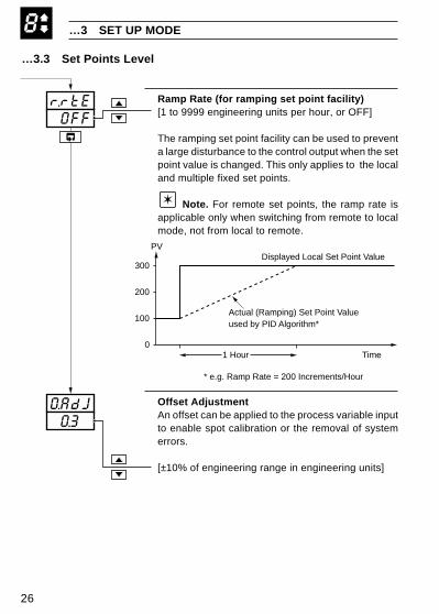
…3.3 Set Points Level
Ramp Rate (for ramping set point facility)[1 to 9999 engineering units per hour, or OFF]
The ramping set point facility can be used to preventa large disturbance to the control output when the setpoint value is changed. This only applies to the localand multiple fixed set points.
Note. For remote set points, the ramp rate isapplicable only when switching from remote to localmode, not from local to remote.
Offset AdjustmentAn offset can be applied to the process variable inputto enable spot calibration or the removal of systemerrors.
[±10% of engineering range in engineering units]
8
r.rtE 0FF
O.AdJ 0.3
Actual (Ramping) Set Point Valueused by PID Algorithm*
0
100
200
300
1 Hour
Displayed Local Set Point Value
Time
PV
* e.g. Ramp Rate = 200 Increments/Hour

27
3 SET UP MODE…
3.4 Profile (Level 4)A four segment ramp/soak profile facility is provided. This level can only beaccessed if the profile option is selected in the configuration level. The foursegments are fixed as ramps or soaks as follows:
Level 4 – Profile Level
Note. To select to this frame from anywhere inthis page, press the key for a few seconds.
Start value for 1st Segment (ramp).[Within display range (in engineering units)]
Enter the start value required.
End Value for 1st Segment (ramp).[Within display range (in engineering units)]
Enter the end value required.
Continued on next page.
•1 With the self-seeking set point facility enabled, the first ramp starts at thecurrent process variable value instead of the start value for the 1st segment.
8
200.0End.1
Str.1100.0
LEV4PrFL
10.0
•1
rtE.1
Set PointValue
1 2 3 4Time
rtE.1
SKt.2
rtE.3
SKt.2
End.3
End.1
Str.1

28
…3 SET UP MODE
…3.4 Profile (Level 4)
•1 The engineering value is shown with an extra decimal place (up to amaximum of 3) for greater accuracy in setting the ramp rate.
8
100.0End.3
20.00rtE.3
60.00SKt.2
40.00rtE.1•1
30.00SKt.4
0Time
Set PointValue
Example. Required Ramp Rate 40°C/minRamp Rate set to 40, Time Option set to 'Min' – see section 4.3.2
2 Min
801st Segment
40
Ramp Rate for 1st Segment.[Engineering units* ]
Enter the ramp rate required.* The time option Eng Units/hr or Eng Units/min is
set in the configuration level – see section 4.3.2.
Soak Time for 2nd Segment.[0 to 999.9 minutes or hours]*
End Value for 3rd Segment (ramp).[Within display range (in engineering units)]
Ramp Rate for 3rd Segment.[Engineering units/hour or /minute]*
* Depending on the time option selected in theconfiguration level.
Continued on next page.

29
3 SET UP MODE
…3.4 Profile (Level 4)
•2 The engineering value is shown with an extra decimal place (up to amaximum of 3) for greater accuracy in setting the ramp rate.
8
YESS.S.S.P
OFFP.HYS
0rPtS
30.00SKt.4•2 Soak Time for 4th Segment.
[0 to 999.9 minutes or hours]** Depending on the time option selected in the
configuration level.
Self Seeking Set Point Enable.YES – enable self seeking set pointNO – disable self seeking set point
When enabled the controller inserts the currentprocess variable value as the starting point oninitiation of the profile (instead of the start value forsegment 1).
Profile Hysteresis for Guaranteed Ramp/Soak.[In engineering units or OFF = 0]
If the process variable deviates from the set point bymore than the value set, the program is suspendedbut continues automatically when the processvariable returns within the set limits. The hysteresisvalue applies above and below set point under allprogram conditions.
Number of Program Repeats[0 to 99 or infinite (InFt> 100]

30
4 CONFIGURATION MODE
Fig. 4.1 Accessing the Configuration Mode (Config./Normal Switch)
4.1 IntroductionThe Configuration Mode comprises two levels (5 and 6) as shown in Fig. 4.2.
Level 5 is divided into four frames. For most simple applications it is only necessaryto set up the parameters in the first frame.
Note.When in the configuration level:
• All the l.e.d. indicators flash.
• All relays and logic outputs are turned off.
• The analog output reverts to 0% (4mA) output level.
4.2 Accessing the Configuration Mode – Fig. 4.1To access the Configuration Mode set the security switch to the 'Configure' position(levels 1 to 4 cannot be accessed from this setting). When the configurationparameters are programmed, reset the security switch to the 'Normal' position. TheOperating page is displayed automatically .
Normal
Configure

31
4 CONFIGURATION MODE…
Fig. 4.2 Configuration Frames (Levels 5 and 6)
LEV5CnFG
AbCd----
EFGH----
JKLn----
PrSt----
LEV6CnFG
EnGH100.0
EnGL 0.0
rt1.H100.0
rt1.L 0.0
SP-H100.0
SP-L 0.0
SP-1 10.0
SP-2 20.0
SP-3 30.0
SP-4 40.0
OPI.H 100
OP2.H 100
Hardware Assignment andInput Type
Alarms and Set PointTypes
Operator Access andControl Action
Digital Input andSerial Communications
A.PAS 0
S.PAS 0
Addr 1
C-OP 0
rt2.H200.0
rt2.L 0.0

32
…4 CONFIGURATION MODE
4.3 Basic Hardware and Configuration (Level 5)
4.3.1 Hardware Assignment and Input Type – Fig. 4.3
AbCd2400
AbCd2400
AbCd2400
AbCd2400
LEV5CnFG
----EFGH
Level 5 – Configuration
Note. To select this frame from anywhere inthis page, press the key for a few seconds.
'ABCD' Settings
The parameter to be changed is indicated by theletter which is flashing. Parameter options are shownin Fig. 4.3.
A = Hardware configurationb = Input type and rangeC = Temperature unitsd = Process variable display decimal places
Notes.Note 1. When the input type (parameter b) ischanged, the range is set automatically to themaximum permissable for the input type selected.
Note 2. For custom settings contact the localdistributor.
Continued on page 34.

33
4 CONFIGURATION MODE…
Fig. 4.3 Hardware Assignment and Input Type
Frequency Rly 1 Rly 2* Rly 3* Logic O/P An. O/P 1 An. O/P 2* Control Type
O/P 1 Alm 1 Alm 2 O/P 1 PV SP Time Prop. or On/Off
Alm 1 Alm 2 None None O/P 1 PV Analog Prop.
O/P 1 O/P2 Alm 1 O/P 1 PV SP Heat – Time Prop.Cool – Time Prop.
O/P2 Alm 1 Alm 2 O/P2 O/P 1 PV Heat – AnalogCool – TP or On/Off
Alm 1 Alm 2 None O/P 1 PV SP Alm Unit or Logic O/PTime Prop.
Custom Custom Custom Custom Custom Custom Custom
A – Hardware Configuration
Display
b THC Type BE THC Type EJ THC Type JK THC Type Kn THC Type Nr THC Type RS THC Type St THC Type TP PT100 RTD
Display
1 0 to 20 mA2 4 to 20 mA3 0 to 5 V4 1 to 5 V6 0 to 50 mV7 4 to 20 mA (square root lineariser)U Custom Configuration
B – Input Type and Range Configuration
D – Process Variable DisplayDecimal Places
Display
0 xxxx1 xxx . x2 xx . xx3 x . xxx
2400AbCd
AbCd2400
AbCd2400
50Hz 60Hz
1
2
3
4
5
A
b
C
C – Temperature UnitsAbCd2400
Display Temperature Units
C Degrees C*F Degrees F*0 No temperature units
U
d
E
* Only available if option board is fitted
* Temperature inputs only

34
…4 CONFIGURATION MODE
4.3.2 Alarms and Set Point Types – Fig. 4.4
Note. All relays are de-energised in the alarm state.
EFGH3241
EFGH3241
EFGH3241
EFGH3241
----JKLn
'EFGH' Settings
The parameter to be changed is indicated by theletter which is flashing. Parameter options areshown in Fig. 4.4.
E = Alarm 1 typeF = Alarm 2 typeG = Alarm HysteresisH = Set Point type
Note. For custom settings contact the localdistributor.
Continued on page 38.

35
Display
0 None1 High Process2 Low Process3 High Deviation4 Low Deviation5 Loop Break
F – Alarm 2 Type*
Display
0 None1 0.1%2 0.2%3 0.5%4 1.0%5 2.0%6 5.0%U Custom
G – Alarm Hysteresis
Display
0 Local Set Point Only1 Local + Remote Set Point (no Remote Set Point Tracking)**2 Local + Remote Set Point (with Remote Set Point Tracking)**3 Multiple Fixed Set Points4 Ramp/Soak (Time Units in Minutes)5 Ramp/Soak (Time Units in Hours)
H – Set Point Type
Display
0 None1 High Process2 Low Process3 High Deviation4 Low Deviation5 Loop Break
E – Alarm 1 Type*EFGH3241
EFGH3241
3241EFGH
EFGH3241
* Refer to Figs. 4.5 and 4.6 for alarm action
Value in % ofengineeringrange
**Only available if option board is fitted. Remote set point input is 4 to 20 mA
Value in engineering units
4 CONFIGURATION MODE…
Fig. 4.4 Alarms and Set Point Types
Note 1. When custom alarmhysteresis is selected, the alarmhysteresis values are setindividually in the set up level
– see section 3.3
1
2
Note 2. With remote set point tracking enabled the local set pointtracks the remote set point when in the remote set point mode.

36
…4 CONFIGURATION MODE
…4.3.2 Alarms and Set Point Types – Fig. 4.4
Note. All relays are de-energised in the alarm state.
Loop Break AlarmThe loop break alarm indicates a fault in the control loop (e.g. failure of a heatingelement in a furnace). If the control output remains at maximum or minimum for atime exceeding the trip value (in seconds) without any response in the processvalue, the loop break alarm is activated.
Process and Deviation Alarms (High/Low) – Figs 4.5 and 4.6
Fig. 4.5 High and Low Process Alarm Action
Trip point
Alarm on
Alarm off
Alarm on
Alarm off
High Process
Low Process
Hysteresis
Hysteresis
ProcessVariable

37
4 CONFIGURATION MODE…
Fig. 4.6 High and Low Deviation Alarm Action
High Deviation+ve Trip Value
Hysteresis
Alarm on
Alarm off
Control SetPoint
Alarm on
Alarm off
PositiveTrip Value
NegativeTrip Value
High Deviation–ve Trip Value
Alarm on
Alarm offNegativeTrip Value
Positive Trip Value
Low Deviation Alarm
High Deviation Alarm
Control SetPoint
Hysteresis
HysteresisLow Deviation+ve Trip Value
Alarm on
Alarm off
HysteresisLow Deviation–ve Trip Value
ProcessVariable
ProcessVariable

38
…4 CONFIGURATION MODE
4.3.3 Operator Access and Control Action – Fig. 4.7
JKLn2310
JKLn2310
JKLn2310
JKLn2310
----PrSt
'JKLN' Settings
The parameter to be changed is indicated by the letterwhich is flashing. Parameter options are shown in Fig. 4.7.
J = Power recovery modeK = Operator selection enable – control functionsL = Operator selection enable – set point functionsn = Control action
Note. For custom settings contact the localdistributor.
Continued on page 40.

39
4 CONFIGURATION MODE…
Fig. 4.7 Operator Access and Control Action
2310
2310
JKLn
JKLn
JKLn2310Display Mode
0 Last Mode1 Manual with Last Output2 Manual with 0.0% Output3 Manual with 100.0% Output4 AutoU Custom
J – Power Recovery Mode
Display Auto/Manual and Autotune
0 Enable Both Functions1 Disable A/M, Enable Auto-tune2 Enable A/M, Disable Auto-tune3 Disable Both Functions
K – Operator Selection EnableControl Functions
Display Local Set Point Adjustment and Local/Remote Set Point Selection
0 Enable Both Functions1 Disable Set Point Adjust, Enable Local/Remote Selection2 Enable Set Point Adjust, Disable Local Remote Function3 Disable Both Functions
L – Operator Selection Enable – Set Point Functions
Display Heat Action Cool Action
0 Reverse Direct1 Direct Reverse
N – Control Action
2310JKLn
40
…4 CONFIGURATION MODE
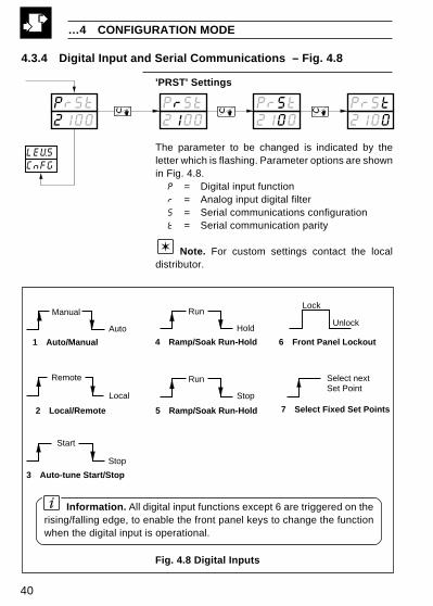
Information. All digital input functions except 6 are triggered on therising/falling edge, to enable the front panel keys to change the functionwhen the digital input is operational.
Fig. 4.8 Digital Inputs
4.3.4 Digital Input and Serial Communications – Fig. 4.8
'PRST' Settings
The parameter to be changed is indicated by theletter which is flashing. Parameter options are shownin Fig. 4.8.
P = Digital input functionr = Analog input digital filterS = Serial communications configurationt = Serial communication parity
Note. For custom settings contact the localdistributor.
PrSt2100
PrSt2100
PrSt2100
PrSt2100
CnFGLEV5
Run
Hold
Start
Stop
Remote
Local
Manual
Auto
Lock
Unlock
Select nextSet Point
Run
Stop
1 Auto/Manual
2 Local/Remote
3 Auto-tune Start/Stop
4 Ramp/Soak Run-Hold
5 Ramp/Soak Run-Hold
6 Front Panel Lockout
7 Select Fixed Set Points

41
4 CONFIGURATION MODE…
Fig. 4.9 Digital Input and Serial Communications
Display
0 None1 Odd2 Even
Display Baud Rate, 2/4 Wire
0 Off1 2400, 2 Wire2 2400, 4 Wire3 9600, 2 Wire4 9600, 4 Wire
S – Serial CommunicationConfiguration
Display
0 0 seconds1 1 second2 2 seconds5 5 secondsA 10 secondsB 20 secondsC 40 secondsD 60 seconds
R – Analog Input Digital Filter
2100 2100PrSt PrSt
PrSt2100
Input filter averages the process
variable input values over the time set
PrSt2100Display Function
0 None1 Auto/Manual2 Local/Remote3 Auto-tune Start4 Ramp/Soak Run-Hold5 Ramp/Soak Run-Stop6 Front Panel Lockout7 Select Fixed Set Points
P – Digital Input Functions
T – Serial CommunicationsParity

42
…4 CONFIGURATION MODE
4.4 Ranges and Passwords (Level 6)
Ranges and Limits
Engineering (Display) Range
High Value[–999 to 9999]
Low Value[–999 to 9999]
Continued on next page…
•1 The engineering range high and low values are automatically set to themaximum allowed value when thermocouple or RTD is selected in theconfiguration level – see Section 4.3.1.
0.0EnGL
EnGH100.0
LEV6CnFG
•1
100.0rt1.H

43
…4.4 Ranges and Passwords (Level 6)
Retransmission RangeThe retransmission range defines engineering rangeto be transmitted
Retransmission High (20mA) Analog Output 1[–999 to 9999 (in engineering units)]
Retransmission Low (4mA) Analog Output 1[–999 to 9999 (in engineering units)]
Retransmission High (20mA) Analog Output 2[–999 to 9999 (in engineering units)]
Retransmission Low (4mA) Analog Output 2[–999 to 9999 (in engineering units)]
Continued on next page…
4 CONFIGURATION MODE…
•1 Only displayed if the analog output is configured to retransmit theprocess variable or control set point value.
•2 Only displayed if the retransmission option board is fitted.
100.0SP-H
•1
100.0rt1.H
0.0rt1.L•1
•2
200.0rt2.H
0.0rt2.L•2

44
…4 CONFIGURATION MODE
…4.4 Ranges and Passwords (Level 6)
Set Point LimitThe Set Point Limit defines limits within which thelocal set point can be adjusted (these limits alsoapply to remote set point).
High Limit[–999 to 9999]
Low Limit[–999 to 9999]
Fixed Set Point Values (1 to 4)Select the set point values required in the multiplefixed set point facility.
Fixed Set Point 1[–999 to 9999 (in engineering units)]
Fixed Set Point 4[–999 to 9999 (in engineering units)]
Continued on next page…
•1 This limit applies to the local and remote set point values.
•2 Only displayed if the multiple fixed set point facility is selected.
0.0SP-L
SP-H100.0
100.0OP1.H
10.0SP-1
30.0SP-4
•1
•2
•1
•2

45
100.0OP2.H
OP1.H100.0
0S.PAS
A.PAS 0
1Addr
•1
•2
•1
C-OP 0
4 CONFIGURATION MODE
…4.4 Ranges and Passwords (Level 6)
Output 1 (Heat) High Limit[0% to 110%]
Output 2 (Cool) High Limit[0% to 110%]
Configured Output[–10% (–110% for heat/cool) to 110% or LASt(default)]This output value is used when:
– Manual control is selected using a digital input,– the process variable input fails,– the auto-tune fails.
Auto-Tune Password[0 to 9999 (default 0)]
Enables access to the auto-tune facility in theoperating level (Level 1).
Setup Password[0 to 9999 (default 0)]
This password enables access to the setup levels(levels 2, 3, and 4) and to the auto tune facility.
MODBUS Address[1 to 99]
This frame allows the MODBUS address to be set.
•1 This value only applies in automatic mode.The low limit is automatically set to 0.0% (–10% for analog outputs).
•2 Only displayed if a heat/cool hardware configuration is selected.

46
5 INSTALLATION
Fig. 5.1 General Requirements
5.1 Siting – Figs. 5.1 and 5.2
Close to the Sensor
Avoid Vibration
At Eye Level
Sensor

47
5 INSTALLATION…
Fig. 5.2 Environmental Requirements
…5.1 Siting – Figs. 5.1 and 5.2
0 to 90% RH
+
IP66/NEMA4X(front panel)
IP20(rear)
Temperature Limits
Environmental Limits
Humidity Limits
Use Screened Cable
55°C (131°F)Max.
0°C (32°F)Min.

48
…5 INSTALLATION
Fig. 5.3 Overall Dimensions
5.2 Mounting – Figs. 5.3 and 5.4The instrument is designed for panel mounting (see Fig. 5.4). Overall dimensionsare shown in Fig. 5.3.
96(3.78)
122.5 (4.82)
17.5(0.69)
Dimensions in mm (in.)
96 (3.78)
PanelCut-out
30 (1.18)
92+0.8–0.0
(3.622 )–0.0+0.03
92+0.8–0.0
(3.622 )–0.0+0.03
14 (0.55)
91.8 (3.61)
5.0(0.2)

49
5 INSTALLATION…
…5.2 Mounting – Figs. 5.3 and 5.4
Fig. 5.4 Mounting Details
1
2 Insert the instrumentinto the panel cut-out
4 Secure the panel clamp using the retaining screws.The rubber friction sleeve prevents over-tightening.
3 Fit the panel clamps, ensuring that the lugsare located correctly in their slots
3
Cut a hole in the panel(see Fig. 5.3 for dimensions).Instruments may be closestacked to DIN 43835

50
EC Directive 89/336/EEC
In order to meet the requirements of the EC Directive 89/336/EEC for EMCregulations, this product must not be used in a non-industrial environment.
5.3 Removing the Instrument from the Case – Fig. 5.5
…5 INSTALLATION
Fig. 5.5 Removing the Instrument from the Case
1 Release the jacking screw cover
2 Turn the jacking screw anticlockwise to pullthe instrument from the case
51
5 INSTALLATION…
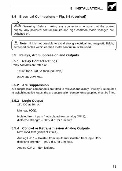
5.4 Electrical Connections – Fig. 5.6 (overleaf)
Warning. Before making any connections, ensure that the powersupply, any powered control circuits and high common mode voltages areswitched off.
Note. If it is not possible to avoid strong electrical and magnetic fields,screened cables within earthed metal conduit must be used.
5.5 Relays, Arc Suppression and Outputs
5.5.1 Relay Contact RatingsRelay contacts are rated at:
115/230V AC at 5A (non-inductive).
250V DC 25W max.
5.5.2 Arc SuppressionArc suppression components are fitted to relays 2 and 3 only. If relay 1 is requiredto switch inductive loads, the arc suppression components supplied must be fitted.
5.5.3 Logic Output18V DC at 20mA.
Min load 900Ω.
Isolated from inputs (not isolated from analog O/P 1),dielectric strength – 500V d.c. for 1 minute.
5.5.4 Control or Retransmission Analog OutputsMax. load 15V (750Ω at 20mA).
Analog O/P 1 – Isolated from inputs (not isolated from logic O/P),dielectric strength – 500V d.c. for 1 minute.
Analog O/P 2 – Non-isolated.

52
Fig. 5.6 Electrical Connections
Note. Analog output 1 and the logic output use a common positiveterminal, capable of driving both outputs simultaneously.
…5 INSTALLATION
AnalogOutput 1
–
+
THCmillivoltsand volts
RTD –
3rd lead
RTD +
3-leadRTD
–
+
Milliamps
1
2
3
4
–
+
* Milliamps
2-wiretransmitter
RTD –
RTD –
RTD +
2-lead RTDand resistance
85 to265V a.c.MainsSupply
C
RelayOutput 1 ***
+
– 1
2
3
4
5
6
7
8
9
10
11
12
25
26
27
28
29
30
31
32
33
34
35
36
–
+
–
L
N
N/C
C
N/O
RelayOutput 2
N/C
C
N/O
AuxiliaryInput
(Remote set point)
DigitalInput
+
–
RS485TX
RS485RX
+
–
RS485
+
+
–
–
Analog Input(see below)
RTD1
Transmitter PSU+
+LogicOutput
** 100Ω
* Using internal transmitter power supply** Use 100Ω shunt resistor provided with the instrument*** Fit the arc suppression component supplied with the instrument
** 100Ω
Tx
RelayO/P 3
N/C
C
N/O
AnalogO/P 2
AnalogO/P 2
1 A fuse
+
–24V d.c.–
+

8CUSTOMER SETUP LOGCustomer Support
ABB Ltd provides a comprehensive aftersales service via our Worldwide ServiceOrganization. Contact one of the followingoffices for details of your nearest Serviceand Repair Centre.
United KingdomABB LtdTel: +44 (0)1480 475 321Fax: +44 (0)1480 470 787
United States of AmericaABB Automation Inc.Instrumentation DivisionTel: +1 215 674 6000Fax: +1 215 674 7183
Client Warranty
Prior to installation, the equipment referred to in this manual must be stored in aclean, dry environment, in accordance with the Company's published specification.Periodic checks must be made on the equipment's condition.
In the event of a failure under warranty, the following documentation must beprovided as substantiation:
1. A listing evidencing process operation and alarm logs at time of failure.
2. Copies of operating and maintenance records relating to the alleged faulty unit.
LEV1OPEr
CodE 0
AtnE OFF
LEV2tUnE
rYc1 5.0
cYc2 5.0
HYSt 0.1
Pb-h100.0
Pb-c100.0
Intr 30
rSEt 50.0
OLAP 0.0
LEV3SEtP
LSPt125.8
rsPn145.8
A1hP800.0
A2hP200.0
rAtO1.000
bIAS 0.0
rrtE OFF
OAdJ 0.3
LEV4PrFL
Str1100.0
End1200.0
rtE1 10.0
SKt2 60.0
End3100.0
rtE3 20.0
SKt4 30.0
SSSP YES
PHYS YES
rPt5 0
Correctpassword
Company Standard settings areshown in the lower display
Instrument Serial Number:
C 250 /Product Code: /
drIV 1.0
IM/C
250
Issu
e 3
The Company’s policy is one of continuous productimprovement and the right is reserved to modify theinformation contained herein without notice.
© ABB 2001 Printed in UK (11.01)
ABB LtdHoward Road, St. NeotsCambridegshire, PE19 8EUUKTel: +44 (0)1480 475 321Fax:+44 (0)1480 470 787
ABB Automation Inc125 E. County Line RoadWarminster, PA 18974USATel: +1 215 674 6000Fax:+1 215-674 7183
ABB has Sales & Customer Support expertisein over 100 countries worldwide
www.abb.com
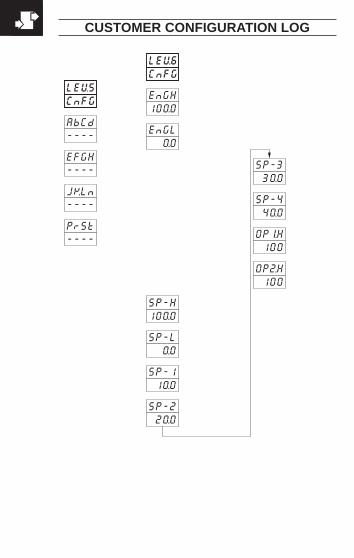
CUSTOMER CONFIGURATION LOG
LEV5CnFG
AbCd----
EFGH----
JKLn----
PrSt----
LEV6CnFG
EnGH100.0
EnGL 0.0
SP-H100.0
SP-L 0.0
SP-1 10.0
SP-2 20.0
SP-3 30.0
SP-4 40.0
OPI.H 100
OP2.H 100
A.PAS 0
S.PAS 0
Addr 1
C-OP 0
Company Standard settings areshown in the lower display
rt1.H100.0
rt1.L 0.0
rt2.H200.0
rt2..L 0.0

8CUSTOMER SETUP LOGCustomer Support
ABB Ltd provides a comprehensive aftersales service via our Worldwide ServiceOrganization. Contact one of the followingoffices for details of your nearest Serviceand Repair Centre.
United KingdomABB LtdTel: +44 (0)1480 475 321Fax: +44 (0)1480 470 787
United States of AmericaABB Automation Inc.Instrumentation DivisionTel: +1 215 674 6000Fax: +1 215 674 7183
Client Warranty
Prior to installation, the equipment referred to in this manual must be stored in aclean, dry environment, in accordance with the Company's published specification.Periodic checks must be made on the equipment's condition.
In the event of a failure under warranty, the following documentation must beprovided as substantiation:
1. A listing evidencing process operation and alarm logs at time of failure.
2. Copies of operating and maintenance records relating to the alleged faulty unit.
LEV1OPEr
CodE 0
AtnE OFF
LEV2tUnE
rYc1 5.0
cYc2 5.0
HYSt 0.1
Pb-h100.0
Pb-c100.0
Intr 30
rSEt 50.0
OLAP 0.0
LEV3SEtP
LSPt125.8
rsPn145.8
A1hP800.0
A2hP200.0
rAtO1.000
bIAS 0.0
rrtE OFF
OAdJ 0.3
LEV4PrFL
Str1100.0
End1200.0
rtE1 10.0
SKt2 60.0
End3100.0
rtE3 20.0
SKt4 30.0
SSSP YES
PHYS YES
rPt5 0
Correctpassword
Company Standard settings areshown in the lower display
Instrument Serial Number:
C 250 /Product Code: /
drIV 1.0

IM/C
250
Issu
e 3
The Company’s policy is one of continuous productimprovement and the right is reserved to modify theinformation contained herein without notice.
© ABB 2001 Printed in UK (11.01)
ABB LtdHoward Road, St. NeotsCambridegshire, PE19 8EUUKTel: +44 (0)1480 475 321Fax:+44 (0)1480 470 787
ABB Automation Inc125 E. County Line RoadWarminster, PA 18974USATel: +1 215 674 6000Fax:+1 215-674 7183
ABB has Sales & Customer Support expertisein over 100 countries worldwide
www.abb.com
CUSTOMER CONFIGURATION LOG
LEV5CnFG
AbCd----
EFGH----
JKLn----
PrSt----
LEV6CnFG
EnGH100.0
EnGL 0.0
SP-H100.0
SP-L 0.0
SP-1 10.0
SP-2 20.0
SP-3 30.0
SP-4 40.0
OPI.H 100
OP2.H 100
A.PAS 0
S.PAS 0
Addr 1
C-OP 0
Company Standard settings areshown in the lower display
rt1.H100.0
rt1.L 0.0
rt2.H200.0
rt2..L 0.0