comfort control center 2 thermostat operating …
TRANSCRIPT

USASERVICE OFFICE
Dometic Corporation1120 North Main Street
Elkhart, IN 46514
CANADADometic Corporation46 Zatonski, Unit 3
Brantford, ON N3T 5L8CANADA
For Service Center &Dealer Locations
Please Visit:www.eDometic.com
COMFORT CONTROL CENTER 2 THERMOSTAT
OPERATING INSTRUCTIONS
REVISION BForm No. 3314149.018 08/16
(French 3314169.016_B)©2016 Dometic Corporation
LaGrange, IN 46761
PROGRAMMABLE THERMOSTAT
MODEL 3314080.000 BLACK3314080.015 WHITE

2
TABLE OF CONTENTSINTRODUCTION ...........................................................................................................................................2DOCUMENT SYMBOLS ...............................................................................................................................3ABOUT YOUR NEW THERMOSTAT ............................................................................................................3
A. Features ....................................................................................................................................3B. SystemConfiguration&Initialization .........................................................................................3C. QuickReferenceToControlButtons .........................................................................................5D. Quick Reference To LCD Icons .................................................................................................5
PROGRAMMING&OPERATIONS ...............................................................................................................6A. ON/OFF .....................................................................................................................................6B. ClockSetting .............................................................................................................................6C. Temperature Format °F / °C ......................................................................................................7D. Inside Temperature ....................................................................................................................7E. ZoneSelection ...........................................................................................................................8F. ModeSelection ..........................................................................................................................8G. Fan Speed .................................................................................................................................9H. Temperature Set-Point ...............................................................................................................9
MODE DESCRIPTION ................................................................................................................................10A. “OFF” - Off Mode .....................................................................................................................10B. “COOL”-CoolMode ...............................................................................................................10C. “HP” - Heat Pump Mode ..........................................................................................................10D. “HS” - Heat Strip Mode ............................................................................................................ 11E. “FAN” - Fan Mode .................................................................................................................... 11F. “FURN” / “AQUA” - Furnace Or Aqua (Hydronic) Heating Mode ............................................. 11G. “AUTO” - Auto Change Over Mode .........................................................................................12
SPECIAL FEATURES..................................................................................................................................12A. Auto Fan ..................................................................................................................................12B. ZoneControl ............................................................................................................................13C. Program“1”&“2” .....................................................................................................................13D. ExamplesOfTimesProgrammed ............................................................................................15E. CANbus Interface ....................................................................................................................15F. AuxiliaryHeat(HeatPumpModelsOnly) ................................................................................16G. StageSelect-TwoAirConditioner/HeatPumpUnits(SelectModels)OnOneZone .............16H. StageSelect-DualCompressorAirConditioner/HeatPump(SelectModels) .......................16I. Auto Generator Start (AGS) ....................................................................................................17J. Load Shed ..............................................................................................................................17K. DefrostCycle(HeatPumpModelsOnly) .................................................................................17L. CompressorTimeDelay ..........................................................................................................17M. PowerInterruption ...................................................................................................................18N. LCD Error Code .......................................................................................................................18
SYSTEM RESET PROCEDURE .................................................................................................................19GENERAL INFORMATION ..........................................................................................................................19
INTRODUCTIONCongratulations!Your recreational vehiclemanufacturer hasequipped yourRVwiththemostadvancedRVthermostat.YourDometicComfortControlCenter2thermostat(hereinafter referred to as the CCC 2 thermostat) has been designed for ease of opera-tionandformanyyearsofreliableservice.
DometicCorporationreservestherighttomodifyappearancesandspecificationswithoutnotice.

3
A. Reduce Heat Gain ...................................................................................................................19B. Disclaimer ................................................................................................................................19
MAINTENANCE ..........................................................................................................................................20A. AirFilter ...................................................................................................................................20B. Dometic CCC 2 Thermostat ....................................................................................................20
SERVICE .....................................................................................................................................................20
TABLE OF CONTENTS
DOCUMENT SYMBOLS
Indicatesadditionalinformationthatisnotrelatedtopersonalinjury.
Indicates step-by-step instructions.
ABOUT YOUR NEW THERMOSTATA. Features
● LiquidCrystalDisplay ● Twooperationprograms ● Constanttimeofdaydisplay ● RemoteSensor(Precisecomfortcontrolwithin1°Fofset-point) ● Displayreminderletsyouknowwhentoserviceorreplacefilters ● UptofourindependentzonesTohelpfamiliarizeyourselfwiththeoperationoftheCCC2thermostat,reviewthefollowingdiagramsandaccompanyingtextthatexplainthefunctionalcharacteris-tics of this system.YourCCC2thermostatisequippedwithaliquidcrystaldisplay(LCD)thatidentifiesthemodeofoperation(OFF,Cool,HeatPump,Fan,HeatStrip,Auto,&FurnaceorAqua), temperature set-point, zone identification (“1”, “2”, “3”, “4”), fan speed(“Auto,” “Low,” “Med,” “High”), program “1” and “2”, inside temperature, clock, °F/°C,compressordelay,andfiltermaintenance.ThemodesofoperationviewedintheLCDwillvarydependingonthesysteminstalledinyourRV.
B. System Configuration & InitializationThe installerofyoursystemwillset therequiredsystemDIPswitchesto theONposition.InorderfortheCCC2thermostattorecognizethesystemzones,typeofunitsinstalledandtheiroptions,asystemresetmustbedone.
4
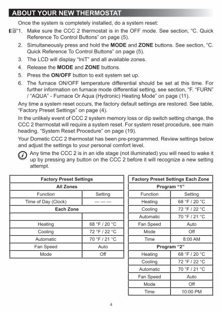
Oncethesystemiscompletelyinstalled,doasystemreset:1. Make sure the CCC 2 thermostat is in the OFF mode. See section, “C. Quick
ReferenceToControlButtons”onpage(5).2. SimultaneouslypressandholdtheMODE and ZONE buttons. See section, “C.
QuickReferenceToControlButtons”onpage(5).3. TheLCDwilldisplay“IniT”andallavailablezones.4. ReleasetheMODE and ZONE buttons.5. Press the ON/OFF button to exit system set up.6. The furnaceON/OFF temperature differential should be set at this time.For
furtherinformationonfurnacemodedifferentialsetting,seesection,“F.“FURN”/ “AQUA” - Furnace Or Aqua (Hydronic) Heating Mode” on page (11).
Anytimeasystemresetoccurs,thefactorydefaultsettingsarerestored.Seetable,“Factory Preset Settings” on page (4).IntheunlikelyeventofCCC2systemmemorylossordipswitchsettingchange,theCCC2thermostatwillrequireasystemreset.Forsystemresetprocedure,seemainheading, “System Reset Procedure” on page (19).YourDometicCCC2thermostathasbeenpre-programmed.Reviewsettingsbelowandadjustthesettingstoyourpersonalcomfortlevel.
AnytimetheCCC2isinanidlestage(notilluminated)youwillneedtowakeitupbypressinganybuttonontheCCC2beforeitwillrecognizeanewsettingattempt.
Factory Preset Settings Factory Preset Settings Each ZoneAll Zones Program “1”
Function Setting Function SettingTimeofDay(Clock) — — — Heating 68 °F / 20 °C
Each Zone Cooling 72 °F / 22 °CAutomatic 70 °F / 21 °C
Heating 68 °F / 20 °C Fan Speed AutoCooling 72 °F / 22 °C Mode Off
Automatic 70 °F / 21 °C Time 8:00AMFan Speed Auto Program “2”
Mode Off Heating 68 °F / 20 °CCooling 72 °F / 22 °C
Automatic 70 °F / 21 °CFan Speed Auto
Mode OffTime 10:00PM
ABOUT YOUR NEW THERMOSTAT

5
C. Quick Reference To Control Buttons
Press to displayinside temperature
Press to selecttemperature format
Press to decreasetemperature set-point
Press to increasetemperature set-pointPress to select zone
Press to select On and OFF
Press to select fan speed
Press to setclock
Press toselect mode
Press to select program 1 or 2
D. Quick Reference To LCD Icons
Temperature Set-Point or Error Code
Operation Mode
Time of Day
Fan Speed
Zone
Program
Clean or Replace FilterCompressor
Delay
ABOUT YOUR NEW THERMOSTAT

6
PROGRAMMING & OPERATIONSA. ON/OFF
ToturnONtheCCC2thermostatwhenthebacklightisOFF,firstpressanybuttontowakeuptheCCC2thermostat.ThenpressandreleasetheON/OFF button. The LCDwilldisplaythelastprogrammedsettings.ToturnOFFtheCCC2thermostatpress the ON/OFFbuttonandrelease.OnlythetimeofdaywilldisplaywhentheCCC 2 thermostat is in the OFF condition.
B. Clock SettingPress the CLOCKbuttontoinitiatetheclocksettingsub-menuontheCCC2ther-mostat. When in this menu, the hourdigitswillflashfirst.Thehourcanbeadjustedusing the ∧ or ∨ buttons. Press the CLOCK button again and the minutedigitswillflash,allowingtheminutesettingtobeadjustedusingthe∧ or ∨ buttons. Press it a third time and the AM or PMiconwillflash,allowingtheAMorPMsettingtobeadjustedusingthe∧ or ∨buttons.Pressitonemoretimetostorethenewtimeinmemoryandexittheclocksettingsub-menu.

7
C. Temperature Format °F / °CPress the °F / °CbuttontoswitchbetweenFahrenheitandCentigradeformat.“°F” indicates Fahrenheit and “°C” indicates Centigrade.
D. Inside TemperaturePressandholdtheINSIDE TEMPbuttonandtheLCDwilldisplaythecurrentinsidetemperature recordedat theCCC2 thermostat (orat theoptional remote indoortemperaturesensor)insteadofthetemperatureset-point.TheLCDwillalsodisplay“IN” to indicate that the inside temperature isbeingdisplayed.Whenthe INSIDE TEMPbuttonisreleased,theLCDwillreturntotheprogrammedtemperatureset-point.
PROGRAMMING & OPERATIONS

8
E. Zone SelectionPress the ZONEbuttontocycletheLCDdisplaythroughtheavailablezoneselec-tions;“Zone1”,“Zone2”,“Zone3”,and“Zone4”.Onlytheavailablezonesinstalledwithin your systemwill display. Formore information on zones, see section, “B.ZoneControl”onpage(13).
F. Mode SelectionPress the MODE buttonand theLCDwill display thefirstavailablemode.Eachsuccessivepresswilladvanceto thenextavailablemode.Continuetopress theMODEbuttonuntilthedesiredmodeappears.Dependingonthesystemsinstalled,yourchoiceswillbe“OFF”,“COOL”,“AUTO”,“HP”,“FURN”or“AQUA”,“HS”,and“FAN”. For more information on modes, see main heading, “Mode Description” on page (10).
PROGRAMMING & OPERATIONS

9
G. Fan SpeedPress the FANbuttontoselectthedesiredfanspeed.Eachsuccessivepresswilladvancetothenextavailablespeed.Yourselectionswillbe“Auto”,“LOW”,“MED”,and“HIGH”.The fanwill runcontinuouslyduring“LOW”, “MED”,and“HIGH” fansettings.ThefanwillcycleONandOFFwiththethermostaton“AUTO”setting.Formore information on auto fan, see section, “A. Auto Fan” on page (12).
H. Temperature Set-PointPress the ∧ or ∨ button to change the temperature set-point. The temperature set-point is indicated by (2) digits on the LCD. Press the ∧ button to increase and the ∨ button to decrease the temperature set-point. The maximum set-point for the system is 90 °F (32 °C). The minimum set-point is determined by the active operat-ingmode.Forheating,theminimumis40°F(4°C)andminimumforcoolingis55°F (13 °C).
PROGRAMMING & OPERATIONS

10
MODE DESCRIPTIONA. “OFF” - Off Mode
DisplaysOFFmodeinazone.
B. “COOL” - Cool ModeIn the COOLmodethesystemwillcyclethecompressorONandOFFbasedonthe room air temperature and the temperature set-point on the CCC 2 thermostat. Whenthesystemcallsforcoolingtherewillbeadelayofapproximately2minutes.Duringthisdelay,thehourglassiconwillbedisplayedintheLCD.Inautofan,thefanwillturnONfirstfollowedbythecompressorinapproximately15seconds.Inthismodethereare(4)fanspeedselections:LOW: Thefanoperatescontinuouslyatlowspeed.ThecompressorcyclesONandOFF.MED: Thefanoperatescontinuouslyatmediumspeed.ThecompressorcyclesONand OFF.HIGH: The fanoperatescontinuouslyathighspeed.ThecompressorcyclesONand OFF.AUTO: Whenautofanisselectedthefanspeedwillvarydependingonthediffer-encebetweenthetemperatureset-pointandtheroomtemperature.InautofanthecompressorandthefanwillcycleONandOFFwiththethermostat.ThecompressorshutsOFFfirstfollowedbythefaninapproximately15seconds.Formoreinforma-tion on auto fan, see section, “A. Auto Fan” on page (12).
C. “HP” - Heat Pump ModeIn the HPmodethesystemwillcyclethecompressorONandOFFbasedontheroom air temperature and the temperature set-point on the CCC 2 thermostat. Whenthesystemcallsforheatingtherewillbeadelayofapproximately2minutes.Duringthisdelay,thehourglassiconwillbedisplayedintheLCD.Inautofan,thecompressorwillturnONfirstfollowedbythefaninapproximately15seconds.Inthismodethereare(4)fanspeedselections:LOW: Thefanoperatescontinuouslyatlowspeed.ThecompressorcyclesONandOFF.MED: Thefanoperatescontinuouslyatmediumspeed.ThecompressorcyclesONand OFF.HIGH: The fanoperatescontinuouslyathighspeed.ThecompressorcyclesONand OFF.AUTO: Whenautofanisselectedthefanspeedwillvarydependingonthediffer-encebetweenthetemperatureset-pointandtheroomtemperature.InautofanthecompressorandfanwillcycleONandOFFwiththethermostat.ThecompressorshutsOFFfirstfollowedbythefaninapproximately15seconds.Formoreinforma-tion on auto fan, see section, “A. Auto Fan” on page (12).

11
D. “HS” - Heat Strip ModeIn the HSmodethesystemwillcycletheheatstripONandOFFbasedontheroomair temperature and the temperature set-point on the CCC 2 thermostat. In this modethereare(4)fanspeedselections:LOW: Thefanoperatescontinuouslyatlowspeed.TheheatstripcyclesONandOFF.MED: Thefanoperatescontinuouslyatmediumspeed.TheheatstripcyclesONand OFF.HIGH: Thefanoperatescontinuouslyathighspeed.TheheatstripcyclesONandOFF.AUTO: ThefanoperatesinlowspeedandwillcycleONandOFFwiththethermo-stat.
E. “FAN” - Fan ModeIn FANmodethereare(4)fanspeedselections:LOW: Thefanoperatescontinuouslyatlowspeed.MED: Thefanoperatescontinuouslyatmediumspeed.HIGH: Thefanoperatescontinuouslyathighspeed.AUTO: ThefanwillbeOFF.
F. “FURN” / “AQUA” - Furnace Or Aqua (Hydronic) Heating Mode(Factory setting is “FURN”)Tochangethesettingfrom“FURN”to“AQUA”orviceversa,simultaneouslypressthe ∧ and ∨buttons.TheLEDwilldisplaytheselectedoption.In the FURN / AQUAmodethesystemwillcycletheRV’sfurnace/aquaONandOFF based on the room air temperature and the temperature set-point on the CCC 2 thermostat.ThesystemcanbeconfiguredtooperateusinganON/OFFdifferentialof either 1 °F / °C or 2 °F / °C. This feature is programmed during the system ini-tialization.Seesection,“B.SystemConfiguration&Initialization”onpage(3).Tosetthe1°F/°Cdifferential,simultaneouslypressthePROGRAM button and the ∧button(“dIF1”willappearinthedisplaywhilethebuttonsarepressed).Tosetthe2°F/°Cdifferential,simultaneouslypressthePROGRAM button and the ∨ button (“dIF2”willappearinthedisplaywhilethebuttonsarepressed).Inthismodethereare(4)fanspeedselections:LOW: Thefanoperatescontinuouslyatlowspeed.MED: Thefanoperatescontinuouslyatmediumspeed.HIGH: Thefanoperatescontinuouslyathighspeed.AUTO: The fan is OFF.
MODE DESCRIPTION

12
G. “AUTO” - Auto Change Over ModeIn the AUTOmodethesystemwillautomaticallychangethemodeofoperationfromcooltoheatorfromheattocool.Inorderforthismodetooperate,thezonebeingprogrammed must contain either a heat pump, heat strip or furnace heating source. When in the AUTOmode,allpre-programmedoperationsfortheheatpump,heatstrip,andfurnacewillapply.Auto Change Over Cooling: If the room temperature rises above the temperature set-pointby2°F/°C,theairconditionerwill turnONuntil theroomtemperaturereachesthetemperatureset-pointatwhichtimetheairconditionerwillcycleOFF.Auto Change Over Heating: Iftheroomtemperaturegoesbelowthetemperatureset-pointby2°F/°C,theavailableheatsourcewillbecycledONuntil theroomtemperaturereachesthetemperaturesetpointatwhichtimeitwillcycleOFF.Ifmorethanoneheatsourceisavailableonthiszone,thepriorityforselectingtheheatsourcewillbeheatpump(first),furnace(second),andheatstrip(third).
SPECIAL FEATURESA. Auto Fan
When“AUTO”fanisselected,thefanspeedwillvarydependingonthedifferencebetweenthetemperatureset-pointandtheroomtemperature.In“AUTO”fan,thecompressorandfanwillcycleONandOFFwiththethermostat.Whenthedifferenceis:8 °F / °C or more The fan operates on HIGH5 to 7 °F / °C The fan operates on MED4°F/°Corless ThefanoperatesonLOW
MODE DESCRIPTION

13
B. Zone ControlZonesareestablishedatthetimeoftheinstallationofyourDometicCCC2thermo-stat.Azoneisanareaofcooling/heatingwhichiscontrolledindependentlybytheCCC2thermostat.TheCCC2thermostatallowsforfourzones(AirConditioner/Heat Pump) to be set up and run independent of each other. If you have one air conditioner/heatpumpinstalled,youwillhaveonezone.IfyourRVhasmorethanonecooling/heatingsystem,youmayhavetwo,three,orfourzones.YourCCC2thermostatwilloperatecoolingandheatingappliancesthatyourvehiclemanufacturerhasdesignedtocoolorheatspecificareas(zones)ofyourRV.TheCCC2thermostatwilladviseyouofthenumberofzonesinyourRV.Thezonesaredisplayed“1”,“2”,“3”,or“4”intheLCDreadout.Seesection,“D.QuickReferenceTo LCD Icons” on page (5).In theeventyourvehiclehasmultiplezonesdesigned,youhave the freedomofselectingdifferentmodesofoperationsforeachzone.Tochangefromonezonetoanother, press the ZONE button on the CCC 2 thermostat. Each time the button is pressedandreleasedtheindicatorwillchangethezonedatadisplayed.Whenthezoneshavebeenprogrammed,thezonesinoperationwillbedisplayed.Toprogrameachzone,simplyrepeattheprogrammingstepsshownundermainheading,“Pro-gramming&Operations”onpage(6).
C. Program “1” & “2”TheDometicCCC2thermostatcanstoretwooperatingprograms.Eachprogramcanbesetonindividualzoneswithdifferentmodeandtimesettingsforeachzone.For each event the user can program the operating mode, fan speed, temperature set-point, and the time of day for the event.1. Selectthezonetobeprogrammed.2. Selectprogram“1”bypressingthePROGRAMbutton.“PROG1”iconwillblink
ontheLCDdisplay.3. Press the CLOCK button to set the time of day for program to start.4. Press the MODEbuttontoselectthemodeofoperation.5. Press the FANbuttontoselectthefanspeed.6. Press the PROGRAMbuttontosavethe“PROG1”settings.LCDwillnowdis-
play“PROG2”.To set program “2”, repeat steps (3) through (5).
7. Press the PROGRAM button again to save program(s) in memory.Dependingonthetimeofday,program“1”or“2”willbeginimmediately.Forinstance,ifprogram“1”issettobeginat10:00AMandthetimeofdayis10:30AM,program“1”willbeginimmediately.Ontheotherhand,ifpro-gram“1”issetto10:00AMandprogram“2”issettobeginat6:00PMandthetimeofdayis7:00PM,program“2”willbeginimmediately.
14
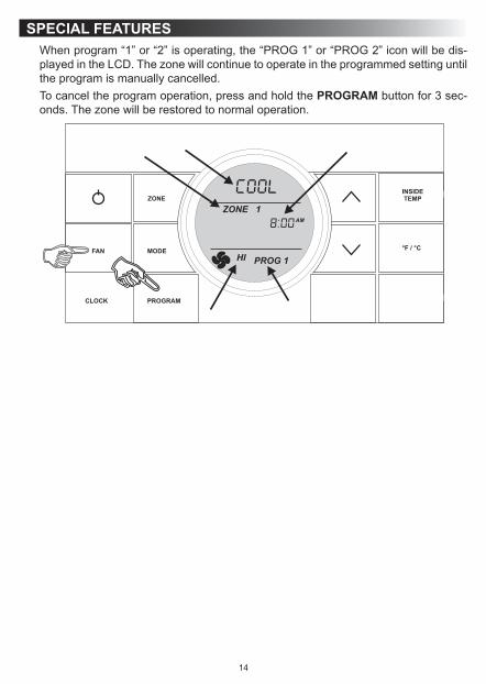
Whenprogram“1”or“2”isoperating,the“PROG1”or“PROG2”iconwillbedis-playedintheLCD.Thezonewillcontinuetooperateintheprogrammedsettinguntiltheprogramismanuallycancelled.Tocanceltheprogramoperation,pressandholdthePROGRAM button for 3 sec-onds.Thezonewillberestoredtonormaloperation.
SPECIAL FEATURES
15
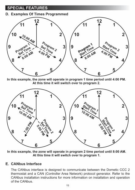
SPECIAL FEATURESD. Examples Of Times Programmed
E. CANbus InterfaceTheCANbus interface isdesignedtocommunicatebetweentheDometicCCC2thermostatandaCAN(ControllerAreaNetwork)protocolgenerator.RefertotheCANbusinstallationinstructionsformoreinformationoninstallationandoperationof the CANbus.

16
F. Auxiliary Heat (Heat Pump Models Only)Auxiliaryheatoperationwillbeactivatedwhen themeasured temperatureof theoutdoortemperaturesensorislessthan30°F(-1°C).Ifthesystemisequippedwithafurnace,thecontrolwillselectFURNheatingmodefortheauxiliaryheatsource.Auxiliaryheatoperation,onceinitiated,willhavepriorityoveraheatpumpdefrostcycle.Auxiliaryheatoperationwillbede-activatedandtheheatpumpoperationwillresumewhen the temperature of theoutdoor temperature sensor is higher than 35 °F (2 °C).
G. Stage Select - Two Air Conditioner/Heat Pump Units (Select Models) On One ZoneThissystemcanbeconfiguredtoruntwoairconditioner/heatpumpunitsusingthesametemperatureset-pointforcontrollingthecomfortlevelinonezone.Oneunitisdesignated as the primary stage and the other unit is designated as the secondary stage.ThepowermoduleboardsinbothunitswillusethesameDIPswitchselec-tionfortheZone(forexample,bothwillbesetto“Zone2”).Ontheunitdesignated“secondary”thepowermoduleboardDIPswitchidentifiedas“ExtStage”mustbeset to theONposition inorder toconfigure thepowermoduleboard for theon-demandsecondarystageoperation(inthisexample“Zone2”and“ExtStage”DIPswitchesareintheONposition).Inthisstageconfiguration,theCCC2thermostattemperatureset-pointwillbeused forboth theprimaryand thesecondarystageairconditioner/heatpump.Onlyoneindoortemperaturesensorisrequiredforthisconfigurationanditmustbeinstalledinthepowermoduleboardconfiguredastheprimarycontrol.The turnON time for thecompressorsand fanswillbecontrolled toensure thatcompressorsonthesystemstartone-at-a-time.Aminimumdelayof20to30sec-ondsisrequiredbetweencompressorstarts.
H. Stage Select - Dual Compressor Air Conditioner/Heat Pump (Select Models)TheDometicCCC2thermostatwilloperateanairconditioner/heatpumpunitwithtwocompressors.Ondualbasementairconditioner/heatpumpunits,asinglepow-ermodule board is used to control the operation of two compressors in oneairconditioner/heatpump.Thissystemisdesignedtooptimizecomfortandoperatingefficiencybyprovidinganon-demandsecondarystageofoperation.TheCCC2thermostatwillallowtheusertosettheprimarytemperatureset-point.Theset-pointforthesecondarystageispresetatadifferentialof3°F/°Cfromtheprimarytem-peratureset-point(thatis,+3°F/°Cforcoolingand-3°F/°Cforheating).Example:Inthecoolingmodewiththeset-pointsetto72°F,theprimaryaircon-ditionerwillcycleONwhentheroomtemperatureis≥73°FThesecondarystagecompressorwillcycleONwhenthetemperatureis≥75°FIntheheatingmodewiththeset-pointat72ºF,theprimarycompressorwillcycleONwhenthetemperatureis≤71°FThesecondarystagecompressorwillcycleONwhentheroomtemperatureis≤69°F.
SPECIAL FEATURES

17
I. Auto Generator Start (AGS)OnRVsequippedwithanoptionalAGSKit,thevehiclegeneratorwillautomaticallystartwhenanyzonecallsforcoolingandwillshutOFFwhenzonesreachsetpoint.TheAutoGeneratorStart(AGS)functionwillbeimplementedbyanindividualpow-ermoduleboardconfiguredforthisfunctionbysettingtheGEN StartDIPswitchON.OntheAGSpowermoduleboardarelayshallbeusedtoprovideastartsignaltothegenerator.Thenormallyopenrelaycontactsareutilizedandtheclosureofthesecontactsprovidesthesignaltostartthegenerator.TheAGSrelayshallbeac-tivatedwhenanyzoneorstagerequirescooling,heatpumporheatstripoperation.Whenazonecallsforheatingorcooling,theAGSrelayshallbeclosed,followedbyatimedelaytoallowthegeneratortowarmupafterwhichtimetheoutputrelaywillbeactivatedonthezonethatinitiatedtheheatingorcoolingrequest.Whentheheat/coolrequestsinallzoneshavebeensatisfied,theAGSrelaywillopenandthegeneratorwillshut-down.
J. Load Shed TheDometicCCC2thermostathasprovisionsforLoadShedding.TheACpow-ermoduleboardshallprovide the12Vdcsource for theLoadShedsignal.This 12VdcsourceshallbeturnedON1secondbeforethecompressorrelaywhenthesystemcallsforthecompressortobeON.TheLoadShedsourceshallremainONwhencompressor iscausedtoturnOFFduetobeingdisablebyeitheraFreezeSensororaLoadShedcondition.TheloadshedsourcesignalwillbeswitchedtotheLoadShedinputbythenormallyopencontactsoranoff-boardrelayfromtheRVpowermanagementsystem.WhentheLoadShedsignalisdetected,thecompres-sorshallturnOFF.
K. Defrost Cycle (Heat Pump Models Only)Toavoid frost formationon theoutsidecoiland toobtainmaximumperformancewhen the outside temperature is less than 42 °F (6 °C) and greater than 30 °F (-1°C),adefrostcyclewillbeinitiated.Whileoperatinginthistemperaturerangethecompressorcontinuousruntimeislimitedto25minutes.Whenthistimeisaccumu-lated,thefanwillshutOFF,therefrigerantflowwillbereversed,andthecompres-sorwillcontinuetorunfor4.5minutes.Duringthis4.5minuteperiod,theLCDwilltogglebetweenHPandDefrost.Therefrigerantflowwillthenbereversedandaftera30seconddelaythefanwillresumeoperation.Thiscyclewillremoveanyfrostformationontheoutsidecoil.Thiscyclewillrepeatitselfuntiltheoutsidetempera-tureisgreaterthan42°F(6°C).Iftheoutsidetemperaturebecomeslessthan30°F(-1°C)theheatpumpwillshutOFFandtheauxiliaryheat(ifprovided)willturnON.
L. Compressor Time DelayAtimedelayofapproximately2minutesoccursanytimethecompressorisrequiredtobeginthecoolingorheatpumpcycle.
SPECIAL FEATURES

18
M. Power InterruptionIntheeventthepowertotheairconditionerorcontrolisinterrupted,thesystemwillrestartwiththeprevioussetpointsoncepowerisrestored.
N. LCD Error CodeWhenthesystemdeterminesthatoneofthefaultslistedbelowhasoccurredaner-rorcodewillbedisplayedintheLCDforthezoneinwhichtheerroroccurred.Duringnormaloperation,ablinkingzonenumberindicatesafaulthasoccurred.Theerrorcodeisdisplayedinplaceofthetemperatureset-point.ErrorCode:E1 LossofcommunicationbetweentheCCC2thermostatandallsystempower
moduleboards.Systemwillshutdown.E1 LossofcommunicationbetweentheCCC2thermostatandanindividualsystem
powermoduleboard.TheLEDwilldisplayerrorcode“E1”andthezonenumberthat lost communication.Any additional zones that loose communicationwillblinkinadditiontothecurrentzone.
E2 Opencircuitorout-of-rangeIndoorTemperatureSensor.Allheatandcoolop-erationwillbelockedout.Manualfanoperationwillcontinue.
E3 ShortedIndoorTemperatureSensor.Allheatandcooloperationwillbelockedout.Manualfanoperationwillcontinue.
E4 OpencircuitoroutofrangeOutdoorTemperatureSensor(selectmodels).Heatpumpoperationwillbelockedout.Airconditioner,furnace,heatstrip,andfanoperation can continue to operate.
E5 Open circuit or out-of-rangeFreezeSensor.Air conditioner operationwill belockedout.Heatpump,furnace,heatstrip,andfanoperationcancontinuetooperatebutdisplaysthelasttemperatureset-point.
E7 Lossof120Vacpowertoallpowermoduleboardsonthesystem.Thesystemwillshutdown.
E8 Invalidzoneconfiguration.TheheatpumpandheatstripDIPswitchesarebothsettotheONpositioninonezone.Heatpump,heatstripandairconditioneroperationwillbelockedoutintheaffectedzone.
E9 Invalid zone configuration. The dehumidifier DIP switch and either the heatpumporheatstripDIPswitchesaresettotheONpositioninonezone.Heatpump,heatstrip,andairconditioneroperationwillbelockedoutintheaffectedzone.
SPECIAL FEATURES

19
SYSTEM RESET PROCEDUREWhenyourunitwasinstalledtheappropriatedipswitchesontheelectroniccontrolboardwereturnedONtomatchyoursystemconfiguration.Anytimethesesettingsarechanged,asystemresetwillneedtobedonebeforetheCCC2thermostatwillrecognizetheupdatedselection.Todoasystemreset:1. Make sure the CCC 2 thermostat is in the OFF mode.2. SimultaneouslypresstheMODE and ZONEbuttons.TheLCDwilldisplay“IniT”
andallavailablezones.3. ReleasetheMODE and ZONE buttons.4. Press the ON/OFF button to exit system set up.
GENERAL INFORMATIONA. Reduce Heat Gain
TheabilityoftheairconditionertomaintainthedesiredinsidetemperaturedependsontheheatgainoftheRV.SomepreventativemeasurestakenbytheoccupantsoftheRVcanreducetheheatgainandimprovetheperformanceoftheaircondi-tioner.Duringextremelyhighoutdoortemperatures,theheatgainoftheRVmaybereducedby: ● ParkingtheRVinashadedarea. ● Usingwindowshades(blindsand/orcurtains). ● Keepingwindowsanddoorsshutorminimizingusage. ● Avoidingtheuseofheatproducingappliances.OperationonHighFan/Coolingmodewillgiveoptimumormaximumefficiencyinhigh humidity or high outside temperatures. Startingtheairconditionerearlyinthemorningandgivingita“headstart”ontheexpectedhighoutdoorambientwillgreatlyimproveitsabilitytomaintainthedesiredindoor temperature. Foramorepermanentsolutiontohighheatgain,accessorieslikeDometicoutdoorpatioandwindowawningswillreduceheatgainbyremovingthedirectsun.Theyalsoaddaniceareatoenjoycompanyduringthecooloftheevening.
B. DisclaimerThemanufacturerof thisunitwillnotberesponsible fordamagecausedbycon-densationformingonceilings,windows,orothersurfaces.AircontainswatervaporwhichcondenseswhentemperatureofasurfaceisbelowDewpoint.Duringnormaloperation this unit is designed to remove a certain amount of moisture from the air, dependingonthesizeofthespacebeingconditioned.Keepingdoorsandwindowsclosedwhen thisairconditioner is inoperationwillgreatly reduce thechanceofcondensation forming on interior surfaces.

20
MAINTENANCEA. Air Filter
Periodic cleaningor replacementof theair conditioner/heat pumpair filtersis required. NEVERruntheairconditionerwithouttheairfilterinplace.Thismayplugtheunitevaporatorcoilwithdirtandmaysubstantiallydegradetheperformance of the unit over time.
Whenasystemfanruntimeexceeds1000hoursthefiltericonisdisplayedintheLCD. (See section, “D. Quick Reference To LCD Icons” on page (5).) When this occurswashthefilterwithsoapandwarmwater.Letdryandreinstall.To reset the fan run time and clear the filter icon, hold the INSIDE TEMP and °F / °Cbuttonsfor3seconds.Thiswillclearthefanruntimeforthecurrentzoneselected.
B. Dometic CCC 2 ThermostatDO NOTspraywaterdirectlyontheCCC2thermostat.DO NOTusesolventsforcleaning.
CleantheCCC2thermostatwithamoistsoftcloth.
SERVICEIntheunlikelyeventtheunitfailstooperateoroperatesimproperly,checkthefol-lowingbeforecallingyourservicecenter. ● IfRVisconnectedtoamotorgenerator,makesurethemotorgeneratorisrun-ningandproducingpower.
● IfRVisconnectedtoapowersupplybyalandline,makesurethelineissizedproperlytorunairconditionerloadanditispluggedintothepowersupply.
● Checkthe120Vacfuseorcircuitbreakertoseeifitisopen.Makesurefuseisnot burnt, or circuit breaker is ”ON” and not activated.
● Checkthe12Vdcfuseorcircuitbreakertoseeifitisopen.Makesurefuseisnotburnt, or circuit breaker is ”ON” and not activated.
● Aftertheabovechecks,callyourlocalservicecenterforfurtherhelp.Thisunitmustbeservicedbyqualifiedservicepersonnelonly.
Whencallingforservice,alwaysgivethefollowing: ● UnitModelNumberandSerialNumberfoundonIdentificationLabellocatedon
the Base Pan of unit bottom. It is necessary to remove the return air cover to exposetheratingplate.
● ElectronicControl Kit PartNumber andSerialNumber found on IdentificationLabellocatedonthesideoftheKit.Thiskitismountedinthereturnaircavityandcan be exposed by removing the return air cover.