combustion manager w-fm 100 und w-fm 200 - … · combustion manager w-fm 100 und w-fm 200 83054802...
TRANSCRIPT

Installation and operating instruction
Combustion manager W-FM 100 und W-FM 200 83054802 1/2015-07
60040000
Conformity certification
Manufacturer: Address: Product: Combustion Manager The product described above conforms with the regulations of directives: This product is labelled as follows:
Schwendi, 05.12.2014
ppa. ppa. Dr. Schloen Denkinger Manager Research Manager Production and and Development Quality Management
Max Weishaupt GmbH
Max-Weishaupt-Straße
D-88475 Schwendi
W-FM 100 / 200
GAD 2009 / 142 / EC PED 97 / 23 / EC LVD 2006 / 95 / EC EMC 2004 / 108 / EC
Sprachschlüssel 02
CE-0085
Installation and operating instructionCombustion manager W-FM 100 und W-FM 200
83054802 1/2015-07 MaW 3-228
1 User instructions .............................................................................................................. 91.1 Target group ........................................................................................................... 91.2 Symbols ................................................................................................................... 91.3 Guarantee and Liability ..................................................................................... 10
2 Safety .................................................................................................................................. 112.1 Designated application ..................................................................................... 112.2 When gas can be smelled ............................................................................... 112.3 Safety measures ................................................................................................. 112.3.1 Normal operation ............................................................................................ 112.3.2 Electrical connection ..................................................................................... 112.3.3 Gas supply ....................................................................................................... 122.4 Alterations to the construction of the equipment ....................................... 122.5 Noise emission ................................................................................................... 122.6 Disposal ............................................................................................................... 12
3 Product description ..................................................................................................... 133.1 Variations ............................................................................................................. 133.2 Function ................................................................................................................ 143.2.1 Burner control .................................................................................................. 143.2.2 Low gas programme ...................................................................................... 143.2.3 Valve proving ................................................................................................... 153.2.4 Load controller ................................................................................................ 163.2.5 Variable speed drive ....................................................................................... 163.2.6 O2 trim / monitoring ....................................................................................... 163.2.7 Program sequence ......................................................................................... 173.2.7.1 Gas direct ignition ...................................................................................... 173.2.7.2 Gas with ignition pilot valve ..................................................................... 183.2.7.3 Light oil direct ignition ............................................................................... 203.2.7.4 Heavy oil direct ignition ............................................................................. 223.2.7.5 Heavy oil with gas pilot ignition ............................................................... 243.3 Inputs .................................................................................................................... 263.3.1 Voltage supply ................................................................................................. 263.3.2 Safety circuit .................................................................................................... 263.3.3 Reset ................................................................................................................. 263.3.4 Air pressure switch ......................................................................................... 263.3.5 Fan contactor contact ................................................................................... 273.3.6 Fuel selection ................................................................................................... 273.3.7 Minimum oil pressure switch ........................................................................ 273.3.8 Maximum oil pressure switch ....................................................................... 273.3.9 Start release Oil .............................................................................................. 283.3.10 Heavy oil immediate start .............................................................................. 283.3.11 Start release Gas ............................................................................................ 283.3.12 Valve proving gas pressure switch ............................................................. 283.3.13 High gas pressure switch ............................................................................. 293.3.14 Low gas pressure switch .............................................................................. 293.3.15 Flame sensor .................................................................................................... 303.3.16 External load controller (X5-03) .................................................................. 323.3.17 External load controller (X62) ...................................................................... 333.3.18 External load controller (Bus) ....................................................................... 33

Installation and operating instructionCombustion manager W-FM 100 und W-FM 200
83054802 1/2015-07 MaW 4-228
3.3.19 Setpoint switch-over ...................................................................................... 343.3.20 Temperature sensor ....................................................................................... 353.3.21 Speed measurement ...................................................................................... 353.3.22 Fuel meter ......................................................................................................... 363.3.23 Flue gas temperature sensor ....................................................................... 363.3.24 Combustion air sensor / CO resistance circuit board ........................... 363.3.25 O2 sensor ......................................................................................................... 373.4 Outputs ................................................................................................................ 383.4.1 Alarm .................................................................................................................. 383.4.2 Motor ................................................................................................................. 383.4.3 Oil pump / magnetic coupling ..................................................................... 383.4.4 Start signal, pressure switch relief .............................................................. 393.4.5 Ignition ............................................................................................................... 393.4.6 Anti syphon valve ............................................................................................ 403.4.7 Oil fuel valves ................................................................................................... 413.4.8 Fuel valves Gas ............................................................................................... 423.4.9 Operating display ........................................................................................... 423.4.10 Analogue output .............................................................................................. 433.4.11 Frequency converter ...................................................................................... 433.5 Technical data ..................................................................................................... 443.5.1 Electrical data .................................................................................................. 443.5.2 Ambient conditions ........................................................................................ 453.5.3 Dimensions ....................................................................................................... 46
4 Installation ........................................................................................................................ 484.1 Installing O2 sensor .......................................................................................... 48
5 Electrical connection .................................................................................................. 50
6 Operation .......................................................................................................................... 556.1 Operating interface ............................................................................................ 556.1.1 Operating panel .............................................................................................. 556.1.2 Display ............................................................................................................... 566.2 Displaying and adjusting parameters ............................................................ 576.2.1 Password .......................................................................................................... 586.3 Menu structure .................................................................................................... 596.4 Operation and system information ................................................................. 686.4.1 Normal operation ............................................................................................ 686.4.2 Fuel selection ................................................................................................... 686.4.3 Operating hours .............................................................................................. 696.4.4 Start-up counter .............................................................................................. 696.4.5 Fuel meter ......................................................................................................... 706.4.6 Number of lockouts ........................................................................................ 716.4.7 Flame signal ..................................................................................................... 716.4.8 Product identification ..................................................................................... 716.4.9 Software version ............................................................................................. 716.4.10 Burner identification ....................................................................................... 716.5 Setting the display ............................................................................................. 736.5.1 Setting the language ...................................................................................... 736.5.2 Set contrast ..................................................................................................... 73

Installation and operating instructionCombustion manager W-FM 100 und W-FM 200
83054802 1/2015-07 MaW 5-228
6.5.3 Date/Time ......................................................................................................... 746.5.4 Units ................................................................................................................... 746.6 Interfaces ............................................................................................................. 756.6.1 Select interfaces ............................................................................................. 756.6.2 eBus ................................................................................................................... 766.6.3 Modbus ............................................................................................................. 766.6.4 Trending data ................................................................................................... 776.7 Manual / Automatic / Off .................................................................................. 786.8 Burner control ..................................................................................................... 796.8.1 Times ................................................................................................................. 796.8.2 Signalling start prevention ............................................................................ 816.8.3 Normal or direct start ..................................................................................... 816.8.4 Oil pump ........................................................................................................... 826.8.5 Forced intermittent ......................................................................................... 826.8.6 Pre-purge Gas ................................................................................................ 826.8.7 Continuous running fan ................................................................................. 836.8.8 Additional air pressure switch ..................................................................... 836.8.9 Configuring input X5-03 ............................................................................... 846.8.10 Configuring output X4-03 ............................................................................ 856.8.11 Extraneous light ............................................................................................... 856.8.12 Repetition counter .......................................................................................... 856.9 Electronic compound ........................................................................................ 856.9.1 Actuator ramps ................................................................................................ 856.9.2 Shutdown behaviour ...................................................................................... 866.9.3 Operating behaviour of frequency converter ............................................ 876.9.4 SpecialPositions ............................................................................................. 886.9.5 Creating load points, modulating operation ............................................. 906.9.6 Operating and switch points, multi-stage operation .............................. 946.9.7 Load range ....................................................................................................... 966.9.8 Load limit .......................................................................................................... 986.9.9 Start point ......................................................................................................... 986.10 O2 controller ....................................................................................................... 996.10.1 O2 controller operating mode .................................................................. 1006.10.2 O2 monitor .................................................................................................... 1026.10.3 O2 trim ........................................................................................................... 1046.10.4 O2 control parameters ............................................................................... 1066.10.5 O2 start mode .............................................................................................. 1106.10.6 Type of Fuel ................................................................................................... 1116.10.7 O2 sensor ...................................................................................................... 1126.10.8 Service interval for O2 sensor .................................................................. 1126.10.9 Define temperature sensor ........................................................................ 1136.10.10 Flue gas temperature warning threshold ................................................ 1136.10.11 Combustion efficiency ................................................................................ 1146.10.12 O2 controller control variable ................................................................... 1146.10.13 Status O2 controller ................................................................................... 1146.10.14 Air rating ......................................................................................................... 1146.10.15 Diagnostic code ........................................................................................... 1156.10.16 O2 content .................................................................................................... 1156.10.17 O2 setpoint ................................................................................................... 116

Installation and operating instructionCombustion manager W-FM 100 und W-FM 200
83054802 1/2015-07 MaW 6-228
6.10.18 Combustion air temperature / CO switching threshold ..................... 1166.10.19 Flue gas temperature .................................................................................. 1166.10.20 O2 sensor temperature .............................................................................. 1166.10.21 O2 sensor heating capacity ...................................................................... 1176.10.22 O2 sensor wear and tear ........................................................................... 1176.10.23 Activate / deactivate O2 controller .......................................................... 1176.11 CO monitor and CO controller ..................................................................... 1186.11.1 Operating mode CO function ................................................................... 1206.11.2 Time delay limit value exceeded ............................................................... 1206.12 Load controller .................................................................................................. 1216.12.1 Setpoint .......................................................................................................... 1216.12.2 Load controller operating mode ............................................................... 1226.12.3 Sensor selection (actual value) ................................................................ 1246.12.4 Analogue inputs ........................................................................................... 1256.12.5 Measuring range .......................................................................................... 1266.12.6 External setpoint .......................................................................................... 1276.12.7 Analogue output ........................................................................................... 1286.12.8 Control parameters of internal load controller ...................................... 1306.12.9 Control variable calming ............................................................................ 1316.12.10 Fault signal suppression ............................................................................ 1316.12.11 Modulating switch differentials ................................................................. 1326.12.12 Multi-stage switch differentials and switch thresholds ....................... 1336.12.12.1 Multi-stage switch differentials ............................................................. 1336.12.12.2 Multi-stage switch threshold ................................................................. 1346.12.12.3 Low impact start ....................................................................................... 1346.12.13 Temperature sensor .................................................................................... 1356.12.14 Boiler cold start function ............................................................................ 1366.12.15 Adaption ......................................................................................................... 1396.13 Actuators ............................................................................................................ 1406.13.1 Addressing .................................................................................................... 1406.13.2 Delete curves ................................................................................................ 1416.13.3 Position control ............................................................................................ 1416.14 VSD / Frequency converter ........................................................................... 1426.14.1 Frequency converter release contact ...................................................... 1426.14.2 Speed measurement ................................................................................... 1426.14.3 Speed standardisation ............................................................................... 1426.14.4 Actual speed ................................................................................................. 1436.14.5 Setpoint output ............................................................................................ 1436.14.6 Speed deviation ........................................................................................... 1436.15 Flue gas recirculation ...................................................................................... 1446.15.1 FGR function ................................................................................................ 1446.15.1.1 Fan on burner ............................................................................................ 1446.15.1.2 Separate fan .............................................................................................. 1466.15.2 FGR operating mode .................................................................................. 1486.15.3 Define temperature sensor ........................................................................ 1496.15.4 FGR sensor temperature ........................................................................... 1496.15.5 FGR release .................................................................................................. 1506.15.6 Temperature compensation ...................................................................... 1506.15.7 Operating temperature ............................................................................... 151
Installation and operating instructionCombustion manager W-FM 100 und W-FM 200
83054802 1/2015-07 MaW 7-228
6.15.8 Position limit FGR damper ........................................................................ 1516.16 Data backup ...................................................................................................... 1526.16.1 Backup copy ................................................................................................. 1526.16.2 Updating software ....................................................................................... 1536.17 TÜV Test ............................................................................................................ 1546.17.1 Flame failure .................................................................................................. 1546.17.2 Safety temperature limiter .......................................................................... 154
7 Commissioning ............................................................................................................ 1557.1 Prerequisite ....................................................................................................... 1557.1.1 Adapting the motor to the frequency converter .................................... 1557.2 Adjusting the burner ........................................................................................ 1567.2.1 Preparatory measures ................................................................................. 1567.2.1.1 Carry out speed standardisation .......................................................... 1577.2.1.2 O2 module presetting ............................................................................. 1587.2.1.3 Deactivate flue gas recirculation ........................................................... 1597.2.2 Adjusting gas side ....................................................................................... 1607.2.3 Adjust modulation oil side .......................................................................... 1667.2.4 Adjust multi-stage oil side ......................................................................... 1727.3 Load controller .................................................................................................. 1767.3.1 Configure load controller ........................................................................... 1767.3.2 Adjust load controller .................................................................................. 1787.3.2.1 Modulating load control .......................................................................... 1787.3.2.2 Modulating load control .......................................................................... 1797.3.2.3 Boiler cold start function ......................................................................... 1807.4 O2 controller ..................................................................................................... 1827.4.1 Set O2 monitor ............................................................................................ 1827.4.2 Set O2 trim ................................................................................................... 1837.4.3 Check and optimise O2 trim ..................................................................... 1847.5 CO controller .................................................................................................... 1867.5.1 Set measurement amplifier LT3 ............................................................... 1867.5.2 Set CO control ............................................................................................. 1877.6 Flue gas recirculation (temperature compensated) ................................. 1887.7 Set pressure switches .................................................................................... 1907.8 Concluding work .............................................................................................. 1907.9 Check combustion ........................................................................................... 1917.10 Calculate gas throughput ............................................................................... 1927.11 Ratings apportionment ................................................................................... 193
8 Servicing .......................................................................................................................... 1948.1 Notes on servicing ........................................................................................... 1948.2 Service plan ....................................................................................................... 195
9 Troubleshooting .......................................................................................................... 1969.1 Procedures for fault conditions ..................................................................... 1969.1.1 Deactivating an alarm ................................................................................. 1979.2 Fault ..................................................................................................................... 1989.3 Lockout ............................................................................................................... 1999.4 Rectifying faults ................................................................................................ 200

Installation and operating instructionCombustion manager W-FM 100 und W-FM 200
83054802 1/2015-07 MaW 8-228
10 Technical documentation ....................................................................................... 21810.1 Frequency converter ....................................................................................... 21810.1.1 Frequency converter Nord size I ... III ...................................................... 21810.1.2 Frequency converter Nord size IV ............................................................ 220
11 Key word index ............................................................................................................ 222

Installation and operating instructionCombustion manager W-FM 100 und W-FM 2001 User instructions
83054802 1/2015-07 MaW 9-228
1 User instructions
Translation of originaloperating instructions
These installation and operating instructions form part of the equipment and mustbe kept on site.Carefully read the installation and operating manual prior to working on the unit.
1.1 Target groupThese installation and operating instructions are intended for the operator and qual-ified personnel. They should be observed by all personnel working with the unit.Work on the unit must only be carried out by personnel who have the relevant train-ing and instruction.Persons with limited physical, sensory or mental capabilities may only work on theunit if they are supervised or have been trained by an authorised person.Children must not play with the unit.
1.2 Symbols
DANGER
Immediate danger with high risk. Non observance can lead to serious injury or death.
WARNING
Danger with medium risk. Non observance can lead to environmental dam-age, serious injury or death.
CAUTION
Danger with low risk. Non observance can cause damage to the equip-ment and injury to personnel.
Important information
Requires direct actionResult after an actionItemisation
… Range of values

Installation and operating instructionCombustion manager W-FM 100 und W-FM 2001 User instructions
83054802 1/2015-07 MaW 10-228
1.3 Guarantee and LiabilityGuarantee and liability claims for personal and equipment damage are excluded, ifthey can be attributed to one or more of the following causes:
non approved application,non-observance of the installation and operating instruction,operation with faulty safety equipment,continual operation despite a fault,improper installation, commissioning, operation and service,repairs, which have been carried out incorrectly,the use of non original Weishaupt parts,force majeure,unauthorised modifications made to the unit,the installation of additional components, which have not been tested with theunit,the installation of combustion chamber inserts, which impede full flame forma-tion,unsuitable fuels,defects in the inlet lines.

Installation and operating instructionCombustion manager W-FM 100 und W-FM 2002 Safety
83054802 1/2015-07 MaW 11-228
2 Safety
2.1 Designated applicationThe combustion manager W-FM 100/200 is suitable for use with:
oil burnersgas burnersdual fuel and triple fuel burners,dual gas burners.
Improper use could:endanger the health and safety of the user or third parties,cause damage to the unit or other material assets.
2.2 When gas can be smelledAvoid open flames and spark generation, for example:
do not operate light switches,do not operate electronic equipment,do not use mobile telephones.Open doors and windows.Close gas isolating valve.Warn the inhabitants (do not ring door bells).Leave the building.Inform the heating contractor or gas supplier from outside of the building.
2.3 Safety measuresSafety relevant fault conditions must be eliminated immediately.Components, which show increased wear and tear or whose design lifespan is orwill be exceeded prior to the next service should be replaced as a precaution[ch. 8.2].
2.3.1 Normal operationAll labels on the unit must be kept in a legible condition.Stipulated settings, service and inspection work should be carried out at regularintervals.Only operate the unit with its cover closed.Do not touch moving parts during operation.Do not touch the oil carrying parts of medium and heavy oil burners during oper-ation.
2.3.2 Electrical connectionFor work carried out on live components:
Observe the accident prevention instructions BGV A3 and adhere to local dir-ectives,tools in accordance with EN 60900 should be used.

Installation and operating instructionCombustion manager W-FM 100 und W-FM 2002 Safety
83054802 1/2015-07 MaW 12-228
2.3.3 Gas supplyOnly the gas supply company or an approved agent may carry out installation, al-teration and maintenance work on gas appliances in buildings and properties.Pipe work must be subject to a combined load and valve proving test and/or us-ability testing relative to the pressure range intended (e. g. DVGW-TRGI, worksheet G 600).Inform the gas supply company about the type and size of plant prior to installa-tion.Local regulations and guidelines must be observed during installation (e. g.DVGW-TRGI, worksheet G 600; TRF Band 1 and Band 2).The gas supply pipe work should be suitable for the type and quality of gas andshould be designed in such a way that it is not possible for liquids to form (e. g.condensate). Observe vaporisation pressure and vaporisation temperature of li-quid petroleum gas.Use only tested and approved sealing materials, whilst observing all process in-formation.Re-commission the appliance when changing to a different type of gas.Changing from LPG to Natural Gas and visa versa requires a conversion.Carry out soundness test after each service and fault rectification.
2.4 Alterations to the construction of the equipmentAll conversions require written approval from Max Weishaupt GmbH.
No additional components may be fitted, which have not been tested for usewith the equipment,do not use combustion chamber inserts, which hinder flame burnout,use only original Weishaupt replacement parts.
2.5 Noise emissionThe noise emissions are determined by the acoustic behaviour of all componentsfitted to the combustion system.Prolonged exposure to high noise levels can lead to loss of hearing. Provide oper-ating personnel with protective equipment.Noise emissions can further be reduced with a sound attenuator.
2.6 DisposalDispose of all materials and components in a safe and environmentally friendly wayat an authorised location. Observe local regulations.

Installation and operating instructionCombustion manager W-FM 100 und W-FM 2003 Product description
83054802 1/2015-07 MaW 13-228
3 Product description
3.1 VariationsType Version FunctionsW-FM 100 LMV51.0… Burner control
Low gas programmeValve proving
LMV51.1… as type LMV51.0…Load controller
W-FM 200 LMV52.2… as type LMV51.1…Variable speed driveO2 trim
LMV52.4… as type LMV52.2…FGR with temperature compensationCO monitor and CO controller func-tion
Installation and operating instructionCombustion manager W-FM 100 und W-FM 2003 Product description
83054802 1/2015-07 MaW 14-228
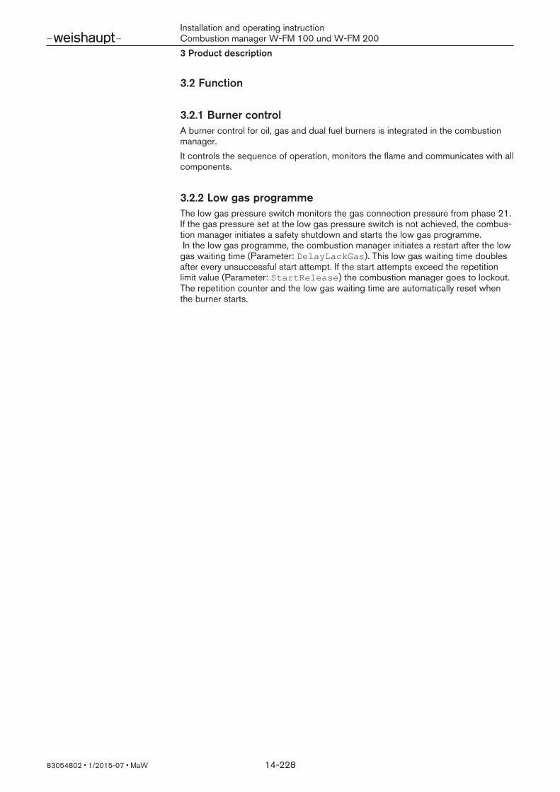
3.2 Function
3.2.1 Burner controlA burner control for oil, gas and dual fuel burners is integrated in the combustionmanager.It controls the sequence of operation, monitors the flame and communicates with allcomponents.
3.2.2 Low gas programmeThe low gas pressure switch monitors the gas connection pressure from phase 21.If the gas pressure set at the low gas pressure switch is not achieved, the combus-tion manager initiates a safety shutdown and starts the low gas programme. In the low gas programme, the combustion manager initiates a restart after the lowgas waiting time (Parameter: DelayLackGas). This low gas waiting time doublesafter every unsuccessful start attempt. If the start attempts exceed the repetitionlimit value (Parameter: StartRelease) the combustion manager goes to lockout.The repetition counter and the low gas waiting time are automatically reset whenthe burner starts.

Installation and operating instructionCombustion manager W-FM 100 und W-FM 2003 Product description
83054802 1/2015-07 MaW 15-228
3.2.3 Valve provingThe valve proving gas pressure switch checks if the valves are tight. It signals thecombustion manager if the pressure increases or decreases to an impermissiblelevel during valve proving.Valve proving is carried out automatically by the combustion manager:
after every controlled shutdown,prior to burner start following lockout or power outage.
1. Test phase (function sequence for valve proving valve 1):Valve 1 remains closed, valve 2 opens,the gas escapes and the pressure between valve 1 and valve 2 reduces,valve 2 closes again,both valves remain closed for 10 seconds.
If the pressure increases to above the set value during these 10 seconds, valve 1 isleaking. The combustion manager initiates a controlled shutdown.2. Test phase (function sequence for valve proving valve 2):
Valve 1 opens, valve 2 remains closed,pressure between valve 1 and valve 2 increases,valve 1 closes again,both valves remain closed for 10 seconds.
If the pressure decreases to below the set value during these 10 seconds, valve 2is leaking. The combustion manager initiates a controlled shutdown.
V1 V2
PP
3 sek 10 sek 10 sek3 sek
80 81 82 83
A
V1 V2
PP
V1 V2
PP
B C
1 2
4
1 2
4
1 2
4
1
2
3
4
5
1 Valve 12 Valve 23 Pressure between valve 1 and valve 24 Valve proving gas pressure switch5 Operating phasesA Direct ignitionB Ignition gas tubeC Gas ignition device
Installation and operating instructionCombustion manager W-FM 100 und W-FM 2003 Product description
83054802 1/2015-07 MaW 16-228
3.2.4 Load controllerThe W-FM 200 is equipped with an internal PID load controller as standard, withthe W-FM 100 the internal load controller is optional.The load controller is suitable for multi-stage and modulating burners. In modulatingoperation, control variables calming reduces the drive impulses and protects theactuators. It is possible to choose between two setpoints using an external contact. The boiler cold start function reduces the thermal load of the heat exchanger duringburner start.
3.2.5 Variable speed driveOnly the W-FM 200 is equipped with a frequency converter module for variablespeed control.Via an analogue output (0/4-20 mA), the W-FM 200 control the frequency con-verter of the fan motor and matches the speed to the burner capacity. This reduceselectrical consumption. The speed and the rotation direction are monitored by an inductive proximity switchand an asymmetrical transmitter disc.
3.2.6 O2 trim / monitoringOnly the W-FM 200 is equipped with an O2 trim function. An additional O2 module(PLL52…) is required for O2 trim.A sensor measures the O2 content in the flue gas. During operation, the W-FM 200compares the O2 content with the setpoints determined during commissioning. Ifdeviations occur, the W-FM 200 activates the air regulating devices and correctsthe O2 content. This increases the boiler efficiency.
Installation and operating instructionCombustion manager W-FM 100 und W-FM 2003 Product description
83054802 1/2015-07 MaW 17-228
3.2.7 Program sequence
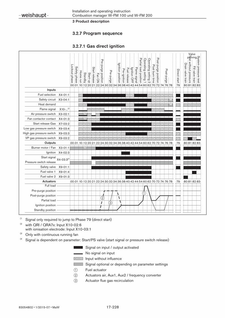
3.2.7.1 Gas direct ignition
79 8382818070 72 74 76 786260544438363432302422212012100100 4240
X4-01:1X3-04:1
X10-...(2
X3-02:1X4-01:3X7-03:2X9-03:4X9-03:3X9-03:2
X3-01:1X4-02:3
79 8382818070 72 74 76 786260544438363432302422212012100100 4240
79 8382818070 72 74 76 786260544438363432302422212012100100 4240
X4-03:3(4
X9-01:1X9-01:4X9-01:3
(1
(1
(3
(3
(3
1
3
2
Lockout phaseS
afety phaseH
ome run
Standby
Start-up
Start release
Fan ON
Pre-purge position
Pre-purge
Ignition positionPre-ignitionFuel releaseIgnition O
FFFlam
e signalPartial load positionO
perating setting 1O
perating setting 2Post burn tim
ePost-purge position
Post-purge
Direct start
Drain valve train
Test without pressure
Fill valve trainS
ystem pressure test
Valveproving
Inputs
Fuel selectionSafety circuitHeat demandFlame signal
Air pressure switchFan contactor contact
Start release GasLow gas pressure switchHigh gas pressure switch
VP gas pressure switchOutputs
Burner motor / FanIgnition
Pressure switch releaseStart signal
Safety valveFuel valve 1Fuel valve 2
ActuatorsFull load
Pre-purge positionPost-purge position
Partial loadIgnition position
Standby position
(1 Signal only required to jump to Phase 79 (direct start)(2 with QRI / QRA7x: Input X10-02:6
with ionisation electrode: Input X10-03:1(3 Only with continuous running fan(4 Signal is dependent on parameter: Start/PS valve (start signal or pressure switch release)
Signal on input / output activatedNo signal on inputInput without influenceSignal optional or depending on parameter settings
1 Fuel actuator2 Actuators air, Aux1, Aux2 / frequency converter3 Actuator flue gas recirculation

Installation and operating instructionCombustion manager W-FM 100 und W-FM 2003 Product description
83054802 1/2015-07 MaW 18-228
3.2.7.2 Gas with ignition pilot valve
79 8382818070 72 74 76 786260544438363432302422212012100100 4240 50 52
X4-01:1X3-04:1
X10-...(2
X3-02:1X4-01:3X7-03:2X9-03:4X9-03:3X9-03:2
X3-01:1X4-02:3
79 8382818070 72 74 76 786260544438363432302422212012100100 4240 50 52
79 8382818070 72 74 76 786260544438363432302422212012100100 4240 50 52
X4-03:3(4
X9-01:1X9-01:2X9-01:4X9-01:3
(1
(1
(3
(3
(3
(5
1
3
2
Lockout phaseS
afety phaseH
ome run
Standby
Start-up
Start release
Fan ON
Pre-purge position
Pre-purge
Ignition positionPre-ignitionFuel releaseIgnition O
FFFlam
e signal
Partial load positionO
perating setting 1O
perating setting 2Post burn tim
ePost-purge position
Post-purge
Direct start
Drain valve train
Test without pressure
Fill valve trainS
ystem pressure test
Valveproving
Inputs
Fuel selectionSafety circuitHeat demandFlame signal
Air pressure switchFan contactor contact
Start release GasLow gas pressure switchHigh gas pressure switch
VP gas pressure switchOutputs
Burner motor / FanIgnition
Pressure switch releaseStart signal
Safety valveIgnition pilot valve
Fuel valve 1
ActuatorsFull load
Pre-purge positionPost-purge position
Partial loadIgnition position
Standby position
Stabilisation of the flam
eIgnition pilot valve O
FF
Fuel valve 2
(1 Signal only required to jump to Phase 79 (direct start)(2 with QRI / QRA7x: Input X10-02:6
with ionisation electrode: Input X10-03:1(3 Only with continuous running fan(4 Signal is dependent on parameter: Start/PS valve (start signal or pressure switch release)(5 If a pilot valve is fitted between fuel valve 1 and 2: Signal from Phase 40
If a gas ignition device is fitted in front of fuel valve 1: Signal from Phase 50

Installation and operating instructionCombustion manager W-FM 100 und W-FM 2003 Product description
83054802 1/2015-07 MaW 19-228
Signal on input / output activatedNo signal on inputInput without influenceSignal optional or depending on parameter settings
1 Fuel actuator2 Actuators air, Aux1, Aux2 / frequency converter3 Actuator flue gas recirculation

Installation and operating instructionCombustion manager W-FM 100 und W-FM 2003 Product description
83054802 1/2015-07 MaW 20-228
3.2.7.3 Light oil direct ignition
7970 72 74 76 786260544438363432302422212012100100 4240
X4-01:2X3-04:1
X10-...(2
X3-02:1X4-01:3X5-01:2X5-02:2X6-01:1
X3-01:1X6-02:3X4-02:3
7970 72 74 76 786260544438363432302422212012100100 4240
7970 72 74 76 786260544438363432302422212012100100 4240
X4-03:3(6
X6-03:3X8-02/03
X7-02:3X7-01:3
(1
(1
(3
(3
(3
(4 (5 (5
(4 (5
(5
1
3
2
Lockout phaseS
afety phaseH
ome run
Standby
Start-up
Start release
Fan ON
Pre-purge position
Pre-purge
Ignition positionPre-ignitionFuel releaseIgnition O
FFFlam
e signalPartial load positionO
perating setting 1O
perating setting 2Post burn tim
ePost-purge position
Post-purge
Direct start
Inputs
Fuel selectionSafety circuitHeat demandFlame signal
Air pressure switchFan contactor contact
Minimum oil pressure switchMaximum oil pressure switch
Start release OilOutputs
Burner motor / Fan
Ignition
Pressure switch releaseStart signal
Anti syphon valveFuel valve 1Fuel valve 2
ActuatorsFull load
Pre-purge positionPost-purge position
Partial loadIgnition position
Standby position
Fuel valve 3
Magnetic coupling / Oil pump
(1 Signal only required to jump to Phase 79 (direct start)(2 with QRI / QRA7x: Input X10-02:6
with QRA2: Input X10-03:1 with QRB: Input X10-02:1
(3 Only with continuous running fan(4 Signal depends on parameter: OnIgnPointOilIgnition (long or short pre-ignition)(5 Signal depends on parameter: OilPumpCoupling (direct coupling)(6 Signal depends on parameter: Start/PS valve

Installation and operating instructionCombustion manager W-FM 100 und W-FM 2003 Product description
83054802 1/2015-07 MaW 21-228
Signal on input / output activatedNo signal on inputInput without influenceSignal optional or depending on parameter settings
1 Fuel actuator2 Actuators air, Aux1, Aux2 / frequency converter3 Actuator flue gas recirculation
Installation and operating instructionCombustion manager W-FM 100 und W-FM 2003 Product description
83054802 1/2015-07 MaW 22-228
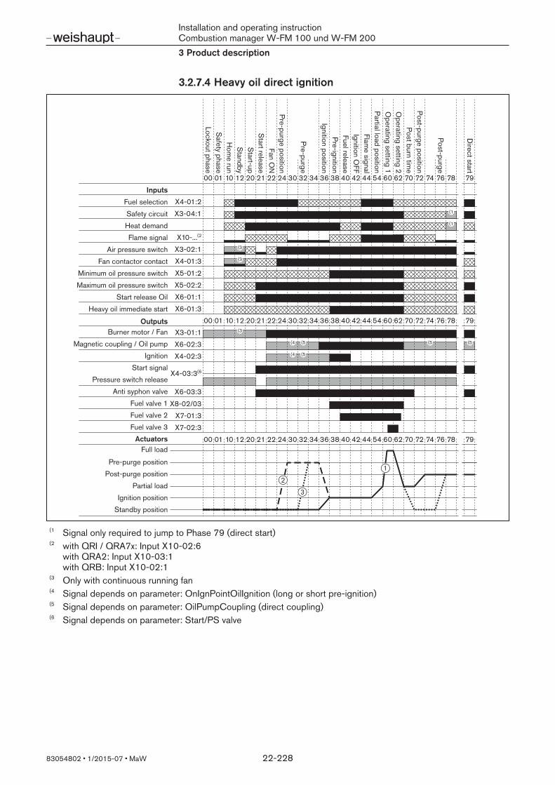
3.2.7.4 Heavy oil direct ignition
(5 (5
7970 72 74 76 786260544438363432302422212012100100 4240
X4-01:2X3-04:1
X10-...(2
X3-02:1X4-01:3X5-01:2X5-02:2
X3-01:1X6-02:3X4-02:3
7970 72 74 76 786260544438363432302422212012100100 4240
7970 72 74 76 786260544438363432302422212012100100 4240
X4-03:3(6
X6-03:3X8-02/03
X7-02:3X7-01:3
(1
(1
(3
(3
(3
(4
(4
X6-01:1X6-01:3
(5
(5
1
3
2
Lockout phaseS
afety phaseH
ome run
Standby
Start-up
Start release
Fan ON
Pre-purge position
Pre-purge
Ignition positionPre-ignitionFuel releaseIgnition O
FFFlam
e signalPartial load positionO
perating setting 1O
perating setting 2Post burn tim
ePost-purge position
Post-purge
Direct start
Inputs
Fuel selectionSafety circuitHeat demandFlame signal
Air pressure switchFan contactor contact
Minimum oil pressure switchMaximum oil pressure switch
Start release Oil
OutputsBurner motor / Fan
Ignition
Pressure switch releaseStart signal
Anti syphon valveFuel valve 1Fuel valve 2
ActuatorsFull load
Pre-purge positionPost-purge position
Partial loadIgnition position
Standby position
Fuel valve 3
Magnetic coupling / Oil pump
Heavy oil immediate start
(1 Signal only required to jump to Phase 79 (direct start)(2 with QRI / QRA7x: Input X10-02:6
with QRA2: Input X10-03:1 with QRB: Input X10-02:1
(3 Only with continuous running fan(4 Signal depends on parameter: OnIgnPointOilIgnition (long or short pre-ignition)(5 Signal depends on parameter: OilPumpCoupling (direct coupling)(6 Signal depends on parameter: Start/PS valve

Installation and operating instructionCombustion manager W-FM 100 und W-FM 2003 Product description
83054802 1/2015-07 MaW 23-228
Signal on input / output activatedNo signal on inputInput without influenceSignal optional or depending on parameter settings
1 Fuel actuator2 Actuators air, Aux1, Aux2 / frequency converter3 Actuator flue gas recirculation

Installation and operating instructionCombustion manager W-FM 100 und W-FM 2003 Product description
83054802 1/2015-07 MaW 24-228
3.2.7.5 Heavy oil with gas pilot ignition
(5 (5
7970 72 74 76 786260544438363432302422212012100100 4240
X4-01:2X3-04:1
X10-...(2
X3-02:1X4-01:3
X5-01:2X5-02:2
X3-01:1X6-02:3X4-02:3
7970 72 74 76 786260544438363432302422212012100100 4240
7970 72 74 76 78626054
52
52
52
50
50
504438363432302422212012100100 4240
X4-03:3(6
X6-03:3X8-02/03
X7-02:3X7-01:3
(1
(1
(3
(3
(3
(4
(4
X6-01:1X6-01:3
X9-03:4X9-03:3
X7-03:2
(5
(5
X9-01:1X9-01:2
1
3
2
Lockout phaseS
afety phaseH
ome run
Standby
Start-up
Start release
Fan ON
Pre-purge position
Pre-purge
Ignition positionPre-ignitionFuel releaseIgnition O
FFFlam
e signal
Partial load positionO
perating setting 1O
perating setting 2Post burn tim
ePost-purge position
Post-purge
Direct start
Inputs
Fuel selectionSafety circuitHeat demandFlame signal
Air pressure switchFan contactor contact
Minimum oil pressure switchMaximum oil pressure switch
Start release Oil
Outputs
Burner motor / Fan
Ignition
Pressure switch releaseStart signal
Anti siphon valve OilFuel valve 1 OilFuel valve 2 Oil
ActuatorsFull load
Pre-purge positionPost-purge position
Partial loadIgnition position
Standby position
Fuel valve 3 Oil
Magnetic coupling / Oil pump
Heavy oil immediate start
Stabilisation of the flam
eIgnition pilot valve O
FF
Low gas pressure switchStart release Gas
High gas pressure switch
Safety valve GasIgnition pilot valve Gas
(1 Signal only required to jump to Phase 79 (direct start)(2 with QRI / QRA7x: Input X10-02:6
with ionisation electrode on gas ignition device: Input X10-03:1(3 Only with continuous running fan(4 Signal depends on parameter: OnIgnPointOilIgnition (long or short pre-ignition)(5 Signal depends on parameter: OilPumpCoupling (direct coupling)(6 Signal depends on parameter: Start/PS valve

Installation and operating instructionCombustion manager W-FM 100 und W-FM 2003 Product description
83054802 1/2015-07 MaW 25-228
Signal on input / output activatedNo signal on inputInput without influenceSignal optional or depending on parameter settings
1 Fuel actuator2 Actuators air, Aux1, Aux2 / frequency converter3 Actuator flue gas recirculation

Installation and operating instructionCombustion manager W-FM 100 und W-FM 2003 Product description
83054802 1/2015-07 MaW 26-228
3.3 Inputs
3.3.1 Voltage supply
2345
X3-0
4
PE
N
L
L
PENL
SAFETYLOOP
LINEVOLTAGE
1 The voltage supply is connected to inputs X3-04:3-5.
3.3.2 Safety circuit
2345
X3-0
4
PE
N
L
L
SAFETYLOOP
LINEVOLTAGE
1
12 X3
-03
L
FLANGE
P
In the diagnostic code, the inputs X3-03:1/2 and X3-04:1/2 are combined assafety circuit. If one of the inputs is open the W-FM carries out at least one safetyshutdown. If the repetition value is exceeded an open input leads to lockout. Therepetition value can be set in parameter RepetitCounter underSafetyLoop, see [ch. 6.8.12].At input X3-04:1/2 all external components of the safety circuit are switched in se-quence, these include:
Emergency-Off switchSafety time limiter (STL)Low water safety interlock, etc.
The burner flange limit switch is connected to input X3-03:1/2.
3.3.3 Reset
2345
X3-0
4
PE
N
L
L
PENL
SAFETYLOOP
LINEVOLTAGE
1
12 X3
-01
L
L MOTOR
ALARM
234
X4-0
1
RESET
OIL
GAS1
(2(1
A reset button can be connected to input X4-01:4. Pressing this button in lockoutwill reset the combustion manager.
With lockout function(1
If the push button is also required for manual lockout, it must be connected tomains input X3-04:5 (L). If the combustion manager is in an operating phase press-ing the button will initiate a manual lockout.
Without lockout function(2
If the push button is not required to carry out manual lockout it must be connectedto alarm output X3-01:2.
3.3.4 Air pressure switch
12 X3
-02
P
L
P Depending on the burner configuration, the input is activated at the factory in theOEM level.The input is activated for:
gas burnersdual fuel burners,oil burners with separately driven pump.
In these cases, the closing contact of the air pressure switch is connected to in-put X3-02:1. The fan will only start, if no signal is present at the input during startrelease. If the signal is missing once the fan has started, the combustion managerinitiates a lockout.
Installation and operating instructionCombustion manager W-FM 100 und W-FM 2003 Product description
83054802 1/2015-07 MaW 27-228
3.3.5 Fan contactor contact
234
X4-01
RESET
OIL
GAS1
12 X3
-02
P
L
P
12 X3
-01
L
L MOTOR
ALARM
(1
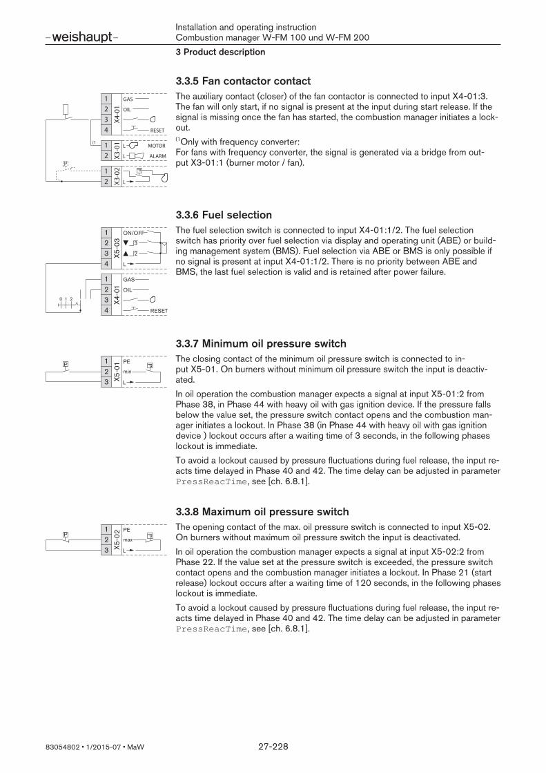
The auxiliary contact (closer) of the fan contactor is connected to input X4-01:3.The fan will only start, if no signal is present at the input during start release. If thesignal is missing once the fan has started, the combustion manager initiates a lock-out.(1Only with frequency converter: For fans with frequency converter, the signal is generated via a bridge from out-put X3-01:1 (burner motor / fan).
3.3.6 Fuel selection
234
X4-0
1
RESET
OIL
GAS1
234
X5-0
3
ON/OFF13
2
L
0 1 2
The fuel selection switch is connected to input X4-01:1/2. The fuel selectionswitch has priority over fuel selection via display and operating unit (ABE) or build-ing management system (BMS). Fuel selection via ABE or BMS is only possible ifno signal is present at input X4-01:1/2. There is no priority between ABE andBMS, the last fuel selection is valid and is retained after power failure.
3.3.7 Minimum oil pressure switch
23 X5
-01 PE
min
1P
L
P The closing contact of the minimum oil pressure switch is connected to in-put X5-01. On burners without minimum oil pressure switch the input is deactiv-ated.In oil operation the combustion manager expects a signal at input X5-01:2 fromPhase 38, in Phase 44 with heavy oil with gas ignition device. If the pressure fallsbelow the value set, the pressure switch contact opens and the combustion man-ager initiates a lockout. In Phase 38 (in Phase 44 with heavy oil with gas ignitiondevice ) lockout occurs after a waiting time of 3 seconds, in the following phaseslockout is immediate.To avoid a lockout caused by pressure fluctuations during fuel release, the input re-acts time delayed in Phase 40 and 42. The time delay can be adjusted in parameterPressReacTime, see [ch. 6.8.1].
3.3.8 Maximum oil pressure switch
23 X5
-02 PE
max
1P
L
P
The opening contact of the max. oil pressure switch is connected to input X5-02. On burners without maximum oil pressure switch the input is deactivated.In oil operation the combustion manager expects a signal at input X5-02:2 fromPhase 22. If the value set at the pressure switch is exceeded, the pressure switchcontact opens and the combustion manager initiates a lockout. In Phase 21 (startrelease) lockout occurs after a waiting time of 120 seconds, in the following phaseslockout is immediate.To avoid a lockout caused by pressure fluctuations during fuel release, the input re-acts time delayed in Phase 40 and 42. The time delay can be adjusted in parameterPressReacTime, see [ch. 6.8.1].

Installation and operating instructionCombustion manager W-FM 100 und W-FM 2003 Product description
83054802 1/2015-07 MaW 28-228
3.3.9 Start release Oil
23 X6
-01
4
1
L
START
L
The start conditions for the oil operation are interrogated via input X6-01:1, e. g.:oil shut off combination limit switch,oil temperature release contact (for heavy oil),cooling air fan contact (WK burners with hot air, version ZMH).
For burners without start conditions, a bridge is connected between terminals 1and 2.In oil operation the combustion manager expects a signal at input X6-01:1fromPhase 21. If the signal is missing after Phase 21, the combustion manager initiatesa shutdown.
3.3.10 Heavy oil immediate start
23 X6
-01
4
1
L
START
L
The input is only activates on heavy oil burners with return flow temperature sensor.The release contact of the return flow temperature sensor is connected to in-put X6-01:3.In heavy oil operation, the combustion manager carries out a nozzle circulation formaximum 45 seconds. If the signal is present at input X6-01:3 before this time haselapsed, the nozzle circulation is shortened accordingly. If the signal is missing afterthis time has elapsed, the combustion manager initiates a home run with sub-sequent repetition.Depending on the burner nozzle circulation is carried out in phase:
38 (with direct ignition),44 (with gas ignition device).
If the signal fails after Phase 44, the combustion manager initiates a safety shut-down.
3.3.11 Start release Gas
23 X7
-031 PE
L
STARTCPI
The input is activated in gas operation and in heavy oil operation with gas ignitiondevice.The combustion manager expects a signal at input X7-03:2 from Phase 21. If thesignal is missing after Phase 21, the combustion manager initiates a shutdown.
3.3.12 Valve proving gas pressure switchL
23 X9
-03
max
min4
1
P
P
P
PLT(CPI)
The opening contact of the valve proving gas pressure switch is connected to in-put X9-04:2. Input X9-04:2 is only activated during valve proving [ch. 3.2.3].If the pressure set is not achieved in Phase 81 (test without pressure), the contactcloses.If the pressure set is exceeded in Phase 83 (test with system pressure), the contactopens.

Installation and operating instructionCombustion manager W-FM 100 und W-FM 2003 Product description
83054802 1/2015-07 MaW 29-228
3.3.13 High gas pressure switchL
23 X9
-03
max
min4
1
P P
P
PLT(CPI)
The input is activated in gas operation and in heavy oil operation with gas ignitiondevice. The opening contact of the high gas pressure switch is connected to in-put X9-03:3. On burners without high gas pressure switch the input is deactivated.The combustion manager expects a signal at input X9-03:3 from Phase 40. If thevalue set at the pressure switch is exceeded, the pressure switch contact opensand the combustion manager initiates a lockout.To avoid lockouts caused by pressure fluctuations when the valves open, the inputreacts time delayed in Phase 40, 42 and 50. The time delay can be adjusted inparameter PressSigReactTime see [ch. 6.8.1].
3.3.14 Low gas pressure switchL
23 X9
-03
max
min4
1
P
P
PLT(CPI)
P
The input is activated in gas operation and in heavy oil operation with gas ignitiondevice. The closing contact of the low gas pressure switch is connected in-put X9-03:4.In gas operation, the combustion manager expects a signal at input X9-03:4 fromPhase 21. If the pressure drops below the value set, the pressure switch contactopens and the combustion manager starts the low gas programme [ch. 3.2.2].To avoid lockouts caused by pressure fluctuations when the valves open, the inputreacts time delayed in Phase 40, 42 and 50. The time delay can be adjusted inparameter PressSigReactTime see [ch. 6.8.1].

Installation and operating instructionCombustion manager W-FM 100 und W-FM 2003 Product description
83054802 1/2015-07 MaW 30-228
3.3.15 Flame sensorIf the flame signal from Phase 44 does not correspond to the value required, thecombustion manager initiates safety shutdown with restart. The number of safetyshutdowns set in parameter LossOfFlame in sequence lead to lockout[ch. 6.8.12]. Depending on parameter ReactionExtranL , a flame signal in Standby(Phase 12) will lead to start prevention or lockout. A flame signal during pre-purge (Phases 30 to 36) or post-purge (Phase 76and 78) leads to lockout after one repetition and repeated occurrence. The OperationalStat shows the current flame signal as a percentage value.
QRB
POWER QRI
L
N
PE
QRI / FSV
23
X10-
02
456
1BN
BK
QRB…The flame sensor QRB… (photo resistor) is connected to input X10-02:1/4. The flame sensor QRB is not suitable for continuous operation.If the combustion manager is installed in a control panel, the sensor cable must berouted separately (max 100 m).
Flame signal Sensor current DisplayMinimum flame signal DC 30 μA approx. 35 %Maximum flame signal DC 70 μA approx. 100 %Extraneous light detectionfrom
DC 5 μA -
QRB
POWER QRI
L
N
PE
QRI / FSV
23
X10-
02
456
1QRI
+
BN
BU
BK
QRIThe flame sensor QRI (infrared) is connected to input X10-02:2/4/6. The flame sensor QRI is suitable for continuous operation. The combustion man-ager tests the flame sensor in cycles in operating position (Phase 60) by simulatinga flame failure. The voltage at output X10-02:2 is increased from 14 V to 21 V for0.5 seconds. The signal voltage at the flame sensor therefore drops to 0 V and thecombustion manager receives the expected Off signal at input X10-02:6.If the combustion manager is installed in a control panel, the sensor cable must berouted separately (max 100 m).
Flame signal DisplayMin. signal voltage: DC 3.5 V (X10-02:6) approx. 50 %
Installation and operating instructionCombustion manager W-FM 100 und W-FM 2003 Product description
83054802 1/2015-07 MaW 31-228
QRB
POWER QRI
L
N
PE
QRI / FSV
23
X10-
02
456
14 5 2 1 3
PE
4 5 6 1 3
PE
+UVM
QRA73
AGM23
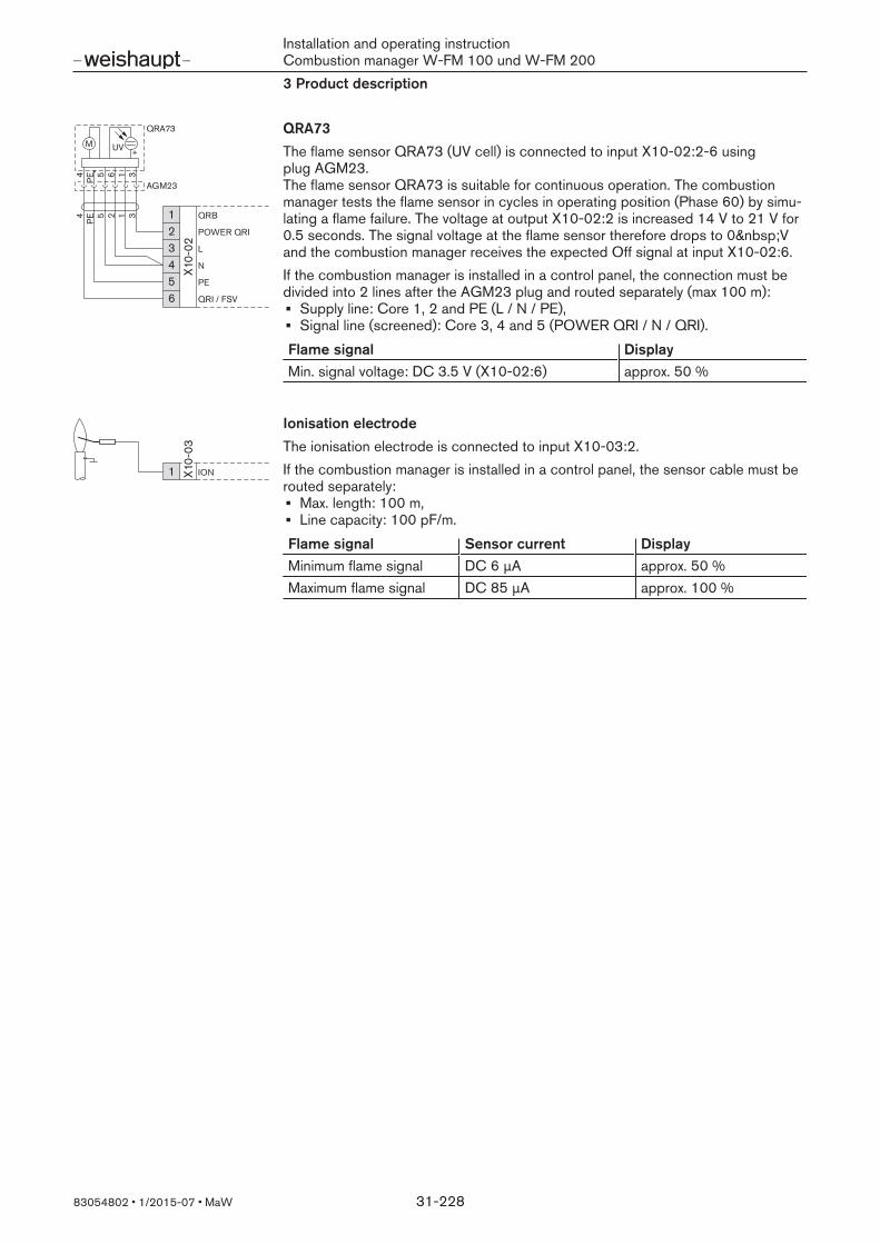
QRA73The flame sensor QRA73 (UV cell) is connected to input X10-02:2-6 usingplug AGM23. The flame sensor QRA73 is suitable for continuous operation. The combustionmanager tests the flame sensor in cycles in operating position (Phase 60) by simu-lating a flame failure. The voltage at output X10-02:2 is increased 14 V to 21 V for0.5 seconds. The signal voltage at the flame sensor therefore drops to 0 Vand the combustion manager receives the expected Off signal at input X10-02:6.If the combustion manager is installed in a control panel, the connection must bedivided into 2 lines after the AGM23 plug and routed separately (max 100 m):
Supply line: Core 1, 2 and PE (L / N / PE),Signal line (screened): Core 3, 4 and 5 (POWER QRI / N / QRI).
Flame signal DisplayMin. signal voltage: DC 3.5 V (X10-02:6) approx. 50 %
X10-
03
ION1
Ionisation electrodeThe ionisation electrode is connected to input X10-03:2.If the combustion manager is installed in a control panel, the sensor cable must berouted separately:
Max. length: 100 m,Line capacity: 100 pF/m.
Flame signal Sensor current DisplayMinimum flame signal DC 6 μA approx. 50 %Maximum flame signal DC 85 μA approx. 100 %
Installation and operating instructionCombustion manager W-FM 100 und W-FM 2003 Product description
83054802 1/2015-07 MaW 32-228
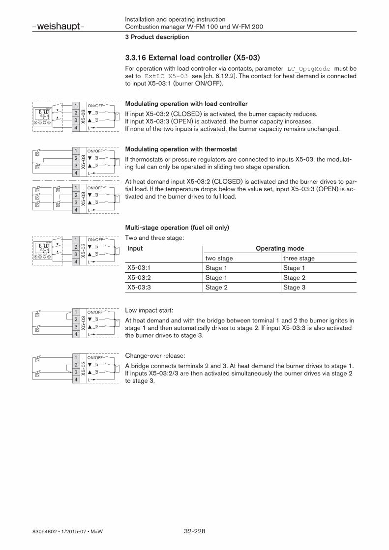
3.3.16 External load controller (X5-03)For operation with load controller via contacts, parameter LC_OptgMode must beset to ExtLC X503 see [ch. 6.12.2]. The contact for heat demand is connectedto input X5-03:1 (burner ON/OFF).
234
X5-0
3
ON/OFF13
2
L
Modulating operation with load controllerIf input X5-03:2 (CLOSED) is activated, the burner capacity reduces. If input X5-03:3 (OPEN) is activated, the burner capacity increases. If none of the two inputs is activated, the burner capacity remains unchanged.
P
P
234
X5-0
3
ON/OFF13
2
L
234
X5-0
3
ON/OFF13
2
LP
P
P
P
P
Modulating operation with thermostatIf thermostats or pressure regulators are connected to inputs X5-03, the modulat-ing fuel can only be operated in sliding two stage operation.
At heat demand input X5-03:2 (CLOSED) is activated and the burner drives to par-tial load. If the temperature drops below the value set, input X5-03:3 (OPEN) is ac-tivated and the burner drives to full load.
Multi-stage operation (fuel oil only)
234
X5-0
3
ON/OFF13
2
L
Two and three stage:
Input Operating modetwo stage three stage
X5-03:1 Stage 1 Stage 1X5-03:2 Stage 1 Stage 2X5-03:3 Stage 2 Stage 3
P
P
234
X5-0
3
ON/OFF13
2
L
Low impact start:At heat demand and with the bridge between terminal 1 and 2 the burner ignites instage 1 and then automatically drives to stage 2. If input X5-03:3 is also activatedthe burner drives to stage 3.
P
P
234
X5-0
3
ON/OFF13
2
L
Change-over release:A bridge connects terminals 2 and 3. At heat demand the burner drives to stage 1.If inputs X5-03:2/3 are then activated simultaneously the burner drives via stage 2to stage 3.

Installation and operating instructionCombustion manager W-FM 100 und W-FM 2003 Product description
83054802 1/2015-07 MaW 33-228
3.3.17 External load controller (X62)
234
X5-0
3
ON/OFF13
2
L
2345
X62
0-10V
4-20mA
0
FE
1
+-
0/2 ... 10 V
0/4 ... 20 mA
For operation with external load controller on the analogue input, parameterLC_OptgMode must be set to Ext LC X62 see [ch. 6.12.2].The contact for heat demand is connected to input X5-03:1 (burner ON/OFF).The analogue load signal is connected to terminals X62:2/4 (0/2-10 V) orX62:3/4 (0/4-20 mA). In parameter Ext Inp X62 U/I the input must bematched to the analogue signal [ch. 6.12.4].
Modulating operationIn modulating operation, parameter MinActuatorStep determines the minimumcorrecting element step [ch. 6.12.9].
Signal on X62 Load W-FM3 … 4 mA 20 %20 mA 100 %
Multi-stage operation (fuel oil only)In multi-stage operation a hysteresis of 1 mA exists between the operating points,which eliminates unnecessary load changes.
Two stage:
Signal on X62 Load W-FM3 … 5 … 12 mA Stage 113 … 15 … 20 mA Stage 2
Three stage:
Signal on X62 Load W-FM3 … 5 … 7 mA Stage 18 … 10 … 12 mA Stage 213 … 15 … 20 mA Stage 3
3.3.18 External load controller (Bus)
X50
interfaceFor the operation with external load controller via Bus connection, parameterLC_OptgMode must be set to ExtLC Bus see [ch. 6.12.2]. The building man-agement system provides the load signal via the bus connection.In modulating operation, parameter MinActuatorStep determines the minimumcorrecting element step [ch. 6.12.9].
Installation and operating instructionCombustion manager W-FM 100 und W-FM 2003 Product description
83054802 1/2015-07 MaW 34-228
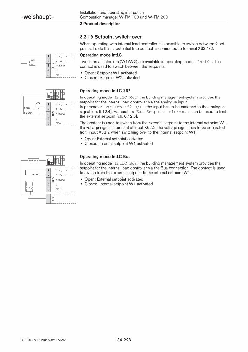
3.3.19 Setpoint switch-overWhen operating with internal load controller it is possible to switch between 2 set-points. To do this, a potential free contact is connected to terminal X62:1/2.
W12345
X62
0-10V
4-20mA
0
FE
1W2
Operating mode IntLCTwo internal setpoints (W1/W2) are available in operating mode IntLC . Thecontact is used to switch between the setpoints.
Open: Setpoint W1 activatedClosed: Setpoint W2 activated
2345
X62
0-10V
4-20mA
0
FE
1W1
0-10V
4-20mA
Operating mode IntLC X62In operating mode IntLC X62 the building management system provides thesetpoint for the internal load controller via the analogue input.In parameter Ext Inp X62 U/I , the input has to be matched to the analoguesignal [ch. 6.12.4]. Parameters Ext Setpoint min/max can be used to limitthe external setpoint [ch. 6.12.6].The contact is used to switch from the external setpoint to the internal setpoint W1.If a voltage signal is present at input X62:2, the voltage signal has to be separatedfrom input X62:2 when switching over to the internal setpoint W1.
Open: External setpoint activatedClosed: Internal setpoint W1 activated
2345
X62
0-10V
4-20mA
0
FE
1
X50
W1
interfaceOperating mode IntLC BusIn operating mode IntLC Bus the building management system provides thesetpoint for the internal load controller via the Bus connection. The contact is usedto switch from the external setpoint to the internal setpoint W1.
Open: External setpoint activatedClosed: Internal setpoint W1 activated

Installation and operating instructionCombustion manager W-FM 100 und W-FM 2003 Product description
83054802 1/2015-07 MaW 35-228
3.3.20 Temperature sensor
FE
23 X6
0
45
1
Pt10
0
Pt/N
i 100
0
Pt100Pt/Ni 1000
P /
FE
0
4-20 mA
0-10 V23 X6
1
45
1 Power SupplySensor
TEM
P.TE
MP.
/PR
ES. I
NP
UT
4...20 mA
GND
IN
0....10 V
If the internal load controller is activated in parameter LC_OptgMode , a temper-ature sensor has to be connected to input X60 or a temperature or pressure sensorhas to be connected to input X61.On W-FM 200 with flue gas recirculation (FGR), the FGR temperature sensor isconnected to input X60:3/4 as standard and is not available for the load controller.As an alternative, the flue gas temperature sensor on the O2 module (accessory)can be used as FGR temperature sensor [ch. 3.3.23]. The sensor used must bedefined in parameter FGRsensor, see [ch. 6.15.3].On W-FM 200 with CO control the combustion air sensor is fitted to input X60:3/4and is not available for the load controller. Parameter AirTempX60PT1000(OEM level) must be set to activated .The internal temperature monitor function is only possible with temperature sensoron input X60. If there is no external safety temperature limiter available in the safetycircuit, two temperature sensors (Pt100/Pt1000 or Pt100/Ni1000) must be con-nected for the internal temperature monitor function. With different cable resistances in the three-wire circuit (Pt100) line compensationis required.Depending on the circuitry, the inputs must be configured via the following para-meters:
Sensor selection [ch. 6.12.3]Ext Inp X61 U/I [ch. 6.12.4]Measuring range [ch. 6.12.5]Additional sensor for boiler start function [ch. 6.12.14].
The voltage supply (20 V DC) on terminal X61:1 can not be changed.
3.3.21 Speed measurement
FE
0
RESERVE
Pulse-In
Usensor
23 X7
0
54
12 wire
3 wire
BN
BU
BN
BK
BU
For operation with frequency converter (W-FM 200 only) the proximity switch forspeed measurement is connected to input X70.Via the transmitter disc, the proximity switch detects 3 impulses per rotation. Thenumber of impulses must be defined in parameter Num Puls per R, see[ch. 6.14.2]. The direction of rotation is detected by the asymmetrical transmitterdisc (60°, 120°, 180°).

Installation and operating instructionCombustion manager W-FM 100 und W-FM 2003 Product description
83054802 1/2015-07 MaW 36-228
3.3.22 Fuel meter
FE
0
Pulse-In
Usensor
23 X7
1
4
1
GA
S
2 wire
3 wire
FE
0
Pulse-In
Usensor
23 X7
2
4
1
OIL
2 wire
3 wire
It is possible to connect 2 fuel meters to the W-FM 200:Gas meter: X71Oil meter: X72
Supply (PIN 1) approx. 10 V DC / max 45 mAInput (PIN 2) max 10 V DC
High level: min 3 V DCLow level: max 1.5 V DC
Sensor Inductive sensor to DIN 19234 (Namur)Open Collector (pnp)Reed contact
Frequency max 300 Hz
The number of impulses per unit of volume must be set in parameterPulseValue… .
3.3.23 Flue gas temperature sensor
23
X86
1
Pt/N
i 100
0FU
EL
GAS
Pt/N
i 100
0 The flue gas temperature sensor is connected to the O2 module input X86 (access-ory).The sensor has to be configured in parameter FlueGasTempSens, see[ch. 6.10.9].Alternatively, the flue gas temperature sensor can be used as FGR temperaturesensor (flue gas recirculation). In parameter FGR sensor X86PtNi1000 must then be defined as FGR temperature sensor [ch. 6.15.3].
3.3.24 Combustion air sensor / CO resistance circuit board
23
X87
1
Pt/N
i 100
0
CO
MB
US
-TI
ON
. AIR
Pt/N
i 100
0
23
X87
1
Pt/N
i 100
0
CO
MB
US
-TI
ON
. AIR
Pt/N
i 100
0
CO
x >
max
The combustion air temperature sensor is connected to the O2 module input X87(accessory).The sensor has to be configured in parameter SupAirTempSens, see[ch. 6.10.9].In conjunction with CO control, a resistance circuit board is connected to inputX87. The digital output 3 of the CO measurement amplifier is connected to the O2
module via the resistance circuit board. The combustion air sensor then has to beconnected to input X60:3/4 [ch. 3.3.20].

Installation and operating instructionCombustion manager W-FM 100 und W-FM 2003 Product description
83054802 1/2015-07 MaW 37-228
3.3.25 O2 sensor
23
X81
456
1
QG
O...
B1
M
B2
M
G2
U3
B1
M
B2
M
G2
U3
Q4
Q5
QGO... GND
23 X8
9-21
QG
O...PE
N
L
Q5
Q4
The O2 sensor is connected to the O2 module (accessory).Connect signal cable (3 x 2 x 0.25 mm2) twisted in pairs to X81. Fit the screensingle-sided to the screen clamp of the O2 module, cable length maximum 10 m.Connect separate cable (3 x 0.75 mm2) for sensor heating to the pulsedoutput X89-2:Q4/Q5.The O2 sensor has to be configured in parameter O2 Sensor, see [ch. 6.10.7].
Terminal FunctionB1 / M Nernst voltage depending on the current O2 content
[ch. 6.10.16].B2 / M Thermo element of the O2 sensor (0 … 33 mV), 700 °C equal to
approx. 29.1 mV.Current operating temperature [ch. 6.10.20].
G2 Voltage supply for temperature compensationU3 Signal of temperature compensationL (Q4)N (Q5)
Pulsed voltage supply for sensor heating 230 V, N (Q5) isswitched. Parameter QGO HeatingLoad shows the currentheating capacity [ch. 6.10.21].
Installation and operating instructionCombustion manager W-FM 100 und W-FM 2003 Product description
83054802 1/2015-07 MaW 38-228
3.4 Outputs
3.4.1 Alarm12 X3
-01 L
L
MOTOR
ALARM
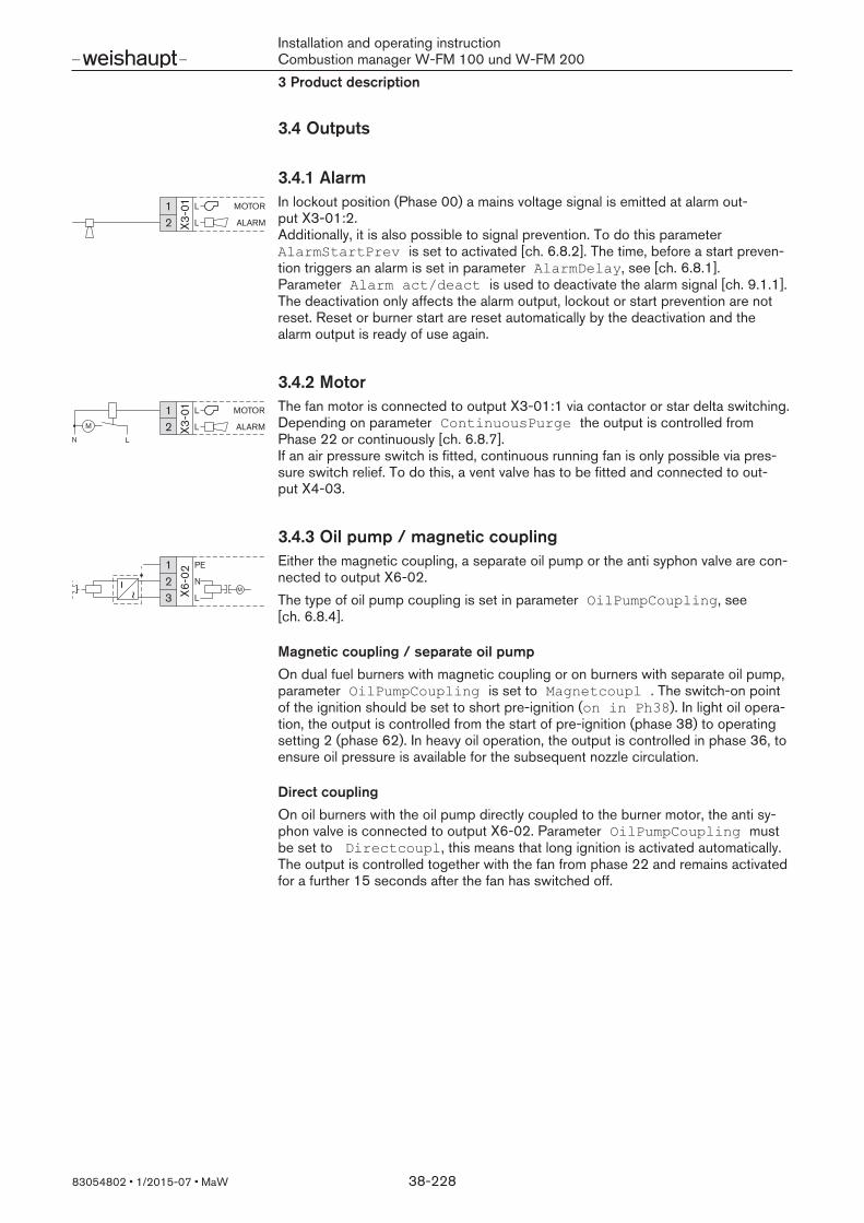
In lockout position (Phase 00) a mains voltage signal is emitted at alarm out-put X3-01:2. Additionally, it is also possible to signal prevention. To do this parameterAlarmStartPrev is set to activated [ch. 6.8.2]. The time, before a start preven-tion triggers an alarm is set in parameter AlarmDelay, see [ch. 6.8.1]. Parameter Alarm act/deact is used to deactivate the alarm signal [ch. 9.1.1].The deactivation only affects the alarm output, lockout or start prevention are notreset. Reset or burner start are reset automatically by the deactivation and thealarm output is ready of use again.
3.4.2 Motor12 X3
-01 L
L
MOTOR
ALARMM
N L
The fan motor is connected to output X3-01:1 via contactor or star delta switching. Depending on parameter ContinuousPurge the output is controlled fromPhase 22 or continuously [ch. 6.8.7]. If an air pressure switch is fitted, continuous running fan is only possible via pres-sure switch relief. To do this, a vent valve has to be fitted and connected to out-put X4-03.
3.4.3 Oil pump / magnetic coupling12
X6-0
2
3
PE
N
LM
~
Either the magnetic coupling, a separate oil pump or the anti syphon valve are con-nected to output X6-02.The type of oil pump coupling is set in parameter OilPumpCoupling, see[ch. 6.8.4].
Magnetic coupling / separate oil pumpOn dual fuel burners with magnetic coupling or on burners with separate oil pump,parameter OilPumpCoupling is set to Magnetcoupl . The switch-on pointof the ignition should be set to short pre-ignition (on in Ph38). In light oil opera-tion, the output is controlled from the start of pre-ignition (phase 38) to operatingsetting 2 (phase 62). In heavy oil operation, the output is controlled in phase 36, toensure oil pressure is available for the subsequent nozzle circulation.
Direct couplingOn oil burners with the oil pump directly coupled to the burner motor, the anti sy-phon valve is connected to output X6-02. Parameter OilPumpCoupling mustbe set to Directcoupl, this means that long ignition is activated automatically.The output is controlled together with the fan from phase 22 and remains activatedfor a further 15 seconds after the fan has switched off.
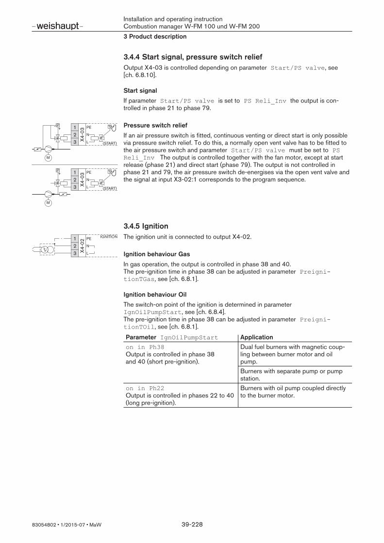
Installation and operating instructionCombustion manager W-FM 100 und W-FM 2003 Product description
83054802 1/2015-07 MaW 39-228
3.4.4 Start signal, pressure switch reliefOutput X4-03 is controlled depending on parameter Start/PS valve, see[ch. 6.8.10].
Start signalIf parameter Start/PS valve is set to PS Reli_Inv the output is con-trolled in phase 21 to phase 79.
12
X4-0
3
3
PE
N
L
M
PP+-
12
X4-0
3
3
PE
N
L
M
PP+
(START)
(START)
Pressure switch reliefIf an air pressure switch is fitted, continuous venting or direct start is only possiblevia pressure switch relief. To do this, a normally open vent valve has to be fitted tothe air pressure switch and parameter Start/PS valve must be set to PSReli_Inv The output is controlled together with the fan motor, except at startrelease (phase 21) and direct start (phase 79). The output is not controlled inphase 21 and 79, the air pressure switch de-energises via the open vent valve andthe signal at input X3-02:1 corresponds to the program sequence.
3.4.5 Ignition12
X4-0
2
3
PE
N
L
IGNITION The ignition unit is connected to output X4-02.
Ignition behaviour GasIn gas operation, the output is controlled in phase 38 and 40. The pre-ignition time in phase 38 can be adjusted in parameter PreignitionTGas, see [ch. 6.8.1].
Ignition behaviour OilThe switch-on point of the ignition is determined in parameterIgnOilPumpStart, see [ch. 6.8.4]. The pre-ignition time in phase 38 can be adjusted in parameter PreignitionTOil, see [ch. 6.8.1].
Parameter IgnOilPumpStart Applicationon in Ph38 Output is controlled in phase 38and 40 (short pre-ignition).
Dual fuel burners with magnetic coup-ling between burner motor and oilpump.Burners with separate pump or pumpstation.
on in Ph22 Output is controlled in phases 22 to 40(long pre-ignition).
Burners with oil pump coupled directlyto the burner motor.
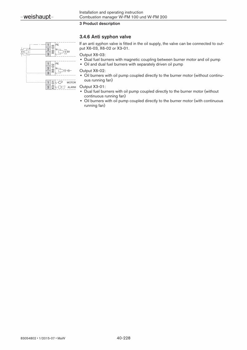
Installation and operating instructionCombustion manager W-FM 100 und W-FM 2003 Product description
83054802 1/2015-07 MaW 40-228
3.4.6 Anti syphon valve12
X6-0
33
PE
N
LSV
12
X6-0
2
3
PE
N
LM
12 X3
-01 L
L
MOTOR
ALARM
If an anti syphon valve is fitted in the oil supply, the valve can be connected to out-put X6-03, X6-02 or X3-01.Output X6-03:
Dual fuel burners with magnetic coupling between burner motor and oil pumpOil and dual fuel burners with separately driven oil pump
Output X6-02:Oil burners with oil pump coupled directly to the burner motor (without continu-ous running fan)
Output X3-01:Dual fuel burners with oil pump coupled directly to the burner motor (withoutcontinuous running fan)Oil burners with oil pump coupled directly to the burner motor (with continuousrunning fan)

Installation and operating instructionCombustion manager W-FM 100 und W-FM 2003 Product description
83054802 1/2015-07 MaW 41-228
3.4.7 Oil fuel valvesThe oil solenoid valves are connected to the outputs X7-01, X7-02, X8-02 andX8-03. The outputs are controlled according to the program sequence [ch. 3.2.7].
L
12
X7-0
1
3
PE
N
LV2
12
X7-0
2
3
PE
N
LV3
12
X8-0
2
34
N
PE
V1
L12
X8-0
3
34
N
PE
V1
2 1
3 2
1
MSEL Multi-stage operation
Output Light oil (EL) Heavy oil (MS) three stage
Heavy oil (MS) two stage
X7-01 Stage 2 Stage 1X7-02 Stage 3 Stage 2X8-02 Stage 1 -X8-03 Additional solenoid valve Additional solenoid valve
Nozzle circulation via output X8-03 is not possible on three stage heavy oil burners,as the combustion manager controls outputs X8-02 and X8-03 simultaneously. Thesolenoid valve for nozzle circulation is connected to output X4-02 (ignition) andparameter IgnOilPumpStart must be set to on in Ph22 (long pre-ignition) [ch. 6.8.4].
12
X7-01
3
PE
N
LV2
L12
X8-02
34
N
PE
V1
MS
ELL1
2
X8-02
34
N
PE
V1
L12
X8-03
34
N
PE
V1
Modulating operation
Output Light oil (EL) Heavy oil (MS)X7-01 - Nozzle solenoid (nozzle head)X8-02 Nozzle solenoid (nozzle head)
-or- Solenoid valves(1
Additional solenoid valves(1
Bypass valve (only with separ-ate pump station)
X8-03 Additional solenoid valves(1 -€€
(1 The solenoid valve in the supply is always switched electrically in series with thesolenoid valve in the return.

Installation and operating instructionCombustion manager W-FM 100 und W-FM 2003 Product description
83054802 1/2015-07 MaW 42-228
3.4.8 Fuel valves GasThe fuel valves are connected to output X9-01. The contacts are controlled in ac-cordance with the program sequence [ch. 3.2.7].
N PE
2
1
12 X9
-02 N
PE
L12
X9-0
1
34
SV
L PV
L V2
L V1
SV
PVL1
2 X9-0
1
34
SV
L PV
L V2
L V1
L12 X9
-01
34
SV
L PV
L V2
L V1
(1
(2
V2 / V1
2
1
N PE L12
X9-0
1
34
SV
L PV
L V2
L V1
Output Fuel valveX9-01:1 (SV) External gas solenoid valve (optional)X9-01:2 (PV) Ignition gas valve(1
- or - Gas ignition device(2
Main gas X9-01:3 (V2) X9-01:4 (V1)
Double gas valve Valve 2 Valve 1
€€
(1 Only for burners with ignition gas tube. (2 Only for heavy oil burners with gas ignition
Valve lift monitoring
12 X9
-02 N
PE
L12
X9-0
1
34
SV
L PV
L V2
L V1
M1
M2
The actuators of double gas valves type VGD (from DN 125) are equipped withlimit switches. The limit switches monitor the valve lift and are switched in se-quence with the voltage supply of actuator V2. At burner start, the limit switches are bridged via a timer relay for approx. 25seconds. If both limit switches are closed once this time has elapsed, valve V2 re-mains open. If a valve does not maintain the the minimum lift, the relevant limit switch opens andinterrupts the voltage from actuator V2. Valve V2 closes and the combustion man-ager initiates a safety shudown with restart. The number of safety shutdowns in se-quence set in parameter LossOfFlame result in a lockout [ch. 6.8.12].
3.4.9 Operating display12 X8
-01 GAS
NOIL
Output X8-01 is controlled together with valve 1 of the current fuel. The output mayonly be used as the operating display.

Installation and operating instructionCombustion manager W-FM 100 und W-FM 2003 Product description
83054802 1/2015-07 MaW 43-228
3.4.10 Analogue output
FE
12 X6
33
0
4-20 mA If the combustion manager is equipped with an internal load controller, a systemvalue can be issued at output X63 via an analogue signal (0/4 … 20 mA). The out-put can be configured in parameter Analog Output, see [ch. 6.12.7].
Load signalIf the parameter Selection analog output is set to Load the analoguesignal corresponds to defined values. For different scaling, the parameter has to beset to Load 0 .
Modulating operation:
Burner rating OFF 0 % 100 %Analogue signal 4 mA 4 mA 20 mA
Multi-stage operation:
Burner rating OFF Stage 1 Stage 2 Stage 3Analogue signal 4 mA 5 mA 10 mA 15 mA
3.4.11 Frequency converter
FE
12
X733
4
65
Start OUT
0
U1
WH
BN
GN
YE
GY
The frequency converter is connected to output X73 using a screened cable(W-FM 200 only). The screen must be connected to ground on both sides.
Terminal (W-FM 200)
Function
X73:1/2 Enable contact: The enable contact for the frequency converter closes from a de-sired speed greater than 0 %. The switch status in phase 10 (home run) for the standby posi-tion (0 %) can be specified via parameterReleasecontctVSD, see [ch. 6.14.1].
X73:3 Alarm input: A signal from the frequency converter (DC 12 … 24 V) results ina safety shutdown.
X73:4/5 Setpoint output (0/4 … 20 mA): The output and input (W-FM 200 / frequency converter) must bematched. The output signal can be set in parameter SetpointOutput, see [ch. 6.14.5].

Installation and operating instructionCombustion manager W-FM 100 und W-FM 2003 Product description
83054802 1/2015-07 MaW 44-228
3.5 Technical data
3.5.1 Electrical data
Combustion Manager W-FM
Mains voltage / Mains frequency (120) 230 V / 50 … 60 HzConsumption max 30 WInternal unit fuse 6.3 AT, IEC 127-2/VExternal fuse max 16 ABType of protection IP 00
Total contact load outputs max 5 AFan motor (output X3-01:1) 1 AAlarm (output X3-01:2) 1 AIgnition (output X4-02) (1.6) 2 APressure switch relief (output X4-03) 0.5 AMagnetic coupling (output X6-02) (1.6) 2 AOil fuel valves (1.6) 1 AFuel valves Gas (1.6) 2 A
Display and operating unit (ABE)
Mains voltage AC 24 VConsumption max 50 mWType of protection (front)Type of protection (rear)
IP54 to ICE 529IP00 to ICE 529
Transformer
Mains voltage / Mains frequency (120) 230 V / 50 … 60 HzSecondary 1 AC 12 VSecondary 2 2 x AC 12 V
Actuator
SQM45… SQM48.497A SQM48.697A SQM91.391A9Mains voltage AC 2 x 12 V AC 2 x 12 V AC 2 x 12 V AC 2 x 12 VConsumption 9 … 15 VA 26 … 34 VA 26 … 34 VA approx. 40 VATorque 3 Nm 20 Nm 35 Nm 60 NmSetting time 10 s / 90° 30 s / 90° 60 s / 90° 30 s / 90°Type of protection IP 54 IP 54 IP 54 IP 66
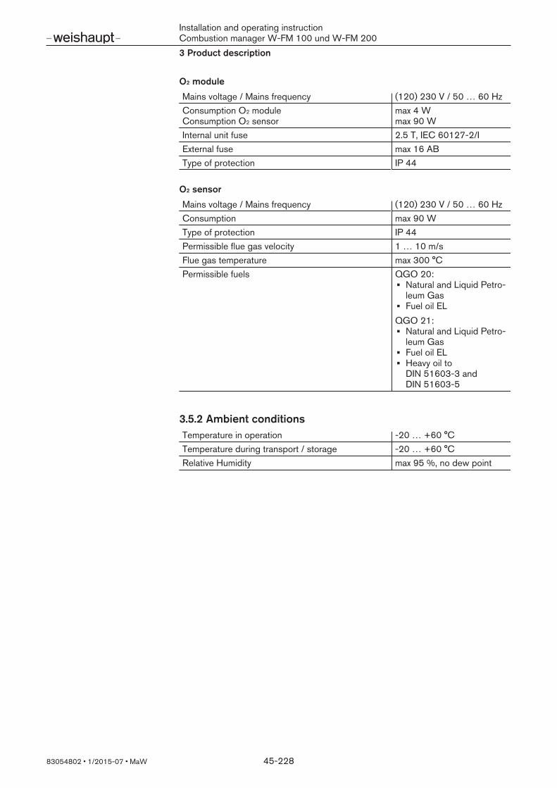
Installation and operating instructionCombustion manager W-FM 100 und W-FM 2003 Product description
83054802 1/2015-07 MaW 45-228
O2 module
Mains voltage / Mains frequency (120) 230 V / 50 … 60 HzConsumption O2 moduleConsumption O2 sensor
max 4 Wmax 90 W
Internal unit fuse 2.5 T, IEC 60127-2/IExternal fuse max 16 ABType of protection IP 44
O2 sensor
Mains voltage / Mains frequency (120) 230 V / 50 … 60 HzConsumption max 90 WType of protection IP 44Permissible flue gas velocity 1 … 10 m/sFlue gas temperature max 300 °CPermissible fuels QGO 20:
Natural and Liquid Petro-leum GasFuel oil EL
QGO 21:Natural and Liquid Petro-leum GasFuel oil ELHeavy oil toDIN 51603-3 andDIN 51603-5
3.5.2 Ambient conditionsTemperature in operation -20 … +60 °CTemperature during transport / storage -20 … +60 °CRelative Humidity max 95 %, no dew point

Installation and operating instructionCombustion manager W-FM 100 und W-FM 2003 Product description
83054802 1/2015-07 MaW 46-228
3.5.3 Dimensions
Combustion Manager
82 mm
260 mm
232 mm20
0 m
m
182
mm
250 mm
Display and operating unit (ABE)Recess dimension: 127 x 91 mm ± 0.5 mm
1924
49 96
90,2
135,
8
126

Installation and operating instructionCombustion manager W-FM 100 und W-FM 2003 Product description
83054802 1/2015-07 MaW 47-228
Transformer
79,5 mm 102,5 mm
120 mm 10,5
mm
40,5
mm
55,5
mm
9 m
m
87 m
m
66,5
mm

Installation and operating instructionCombustion manager W-FM 100 und W-FM 2004 Installation
83054802 1/2015-07 MaW 48-228
4 Installation
4.1 Installing O2 sensor
O2 trim is only possible with W-FM 200 with O2 module. For O2 measurement, an O2 sensor must be fitted in the flue gas pipe and connec-ted to the O2 module. The distance between O2 sensor and O2 module must be nomore than 10 m.
Flange dimensions
90 mm
51 mm
180 / 260 mm
53,5 mm 48 mm
QGO 21QGO 20
Prerequisite
CAUTION
Damage to the O2 sensor caused by overheatingFlue gas temperature above 300 °C can damage the O2 sensor.
Avoid flue gas temperatures above 300 °C at the O2 sensor.
Install O2 sensor only with the corresponding flange.It must not be possible for extraneous air to enter in front of the sensor and at adistance of 2 x Ø of the flue gas pipe behind the sensor.

Installation and operating instructionCombustion manager W-FM 100 und W-FM 2004 Installation
83054802 1/2015-07 MaW 49-228
Installation positionInstall the sensor as close as possible to the flue gas outlet of the boiler, but atleast at a distance of 1 x Ø of the flue gas pipe.Sensor in the horizontal part of the flue gas pipe:
QGO 20: vertically from above or at an angle of 45°.QGO 21: horizontal
Sensor in the vertical part of the flue gas pipe:With a downward inclination of approx. 5°.
45° 45°5°
QGO 21QGO 20min 1 x Ø
Ø
InstallationWeld flange gastight to flue gas pipe 1, with QGO 20 observe the position ofthe flue gas outlet openings 4.Install O2 sensor 2, ensuring correct alignment of the seal 3.Cable entry must be made on the opposite side to the flue gas flow.
1
≥ 10 m
m
2
3
2
31
QGO 20 QGO 21
4

Installation and operating instructionCombustion manager W-FM 100 und W-FM 2005 Electrical connection
83054802 1/2015-07 MaW 50-228
5 Electrical connection
DANGER
Risk of electric shockWorking on the device when voltage is applied can lead to electric shock.
Isolate the device from the power supply prior to starting any work.Safeguard against accidental re-start.
WARNING
Electric shock caused by frequency converter despite disconnection from thevoltage supplyIt is possible that electrical components on burners with frequency converters con-tinue to carry voltage and cause electric shock even after the voltage supply hasbeen disconnected.
Wait approx. 5 minutes before commencing work.Electric voltage has dissipated.
The electrical connection must only be carried out by qualified electricians. Ob-serve local regulations.
Connect combustion managerUse cable entry grommets on the housing.Connect wiring to wiring diagram enclosed.
Control circuits, which are taken directly via a 16 AT pre-fuse from a 3 phase orsingle phase alternating current supply, must only be connected between a phaseconductor and earth potential neutral conductor.On mains supply, which does not have a neutral, the control voltage must be sup-plied via an isolating transformer. The pole of the transformer, which is to be usedas the neutral conductor, must be earthed.Phase L must not be mixed up with the neutral conductor N. Contact protection willotherwise no longer be given. Malfunctions, which endanger operational safetycould occur.The cable cross section of the voltage supply must be suitable for the nominal cur-rent of the pre-fusing (maximum 16 AT). All other cable connections must be suit-able for the relevant internal unit fuse (6.3 AT).Earthing and neutral conductor must conform to local regulations.The following applies for cable length:
all cable lengths maximum 100 m,use only original Weishaupt parts as Bus line,install Bus line as line configuration.
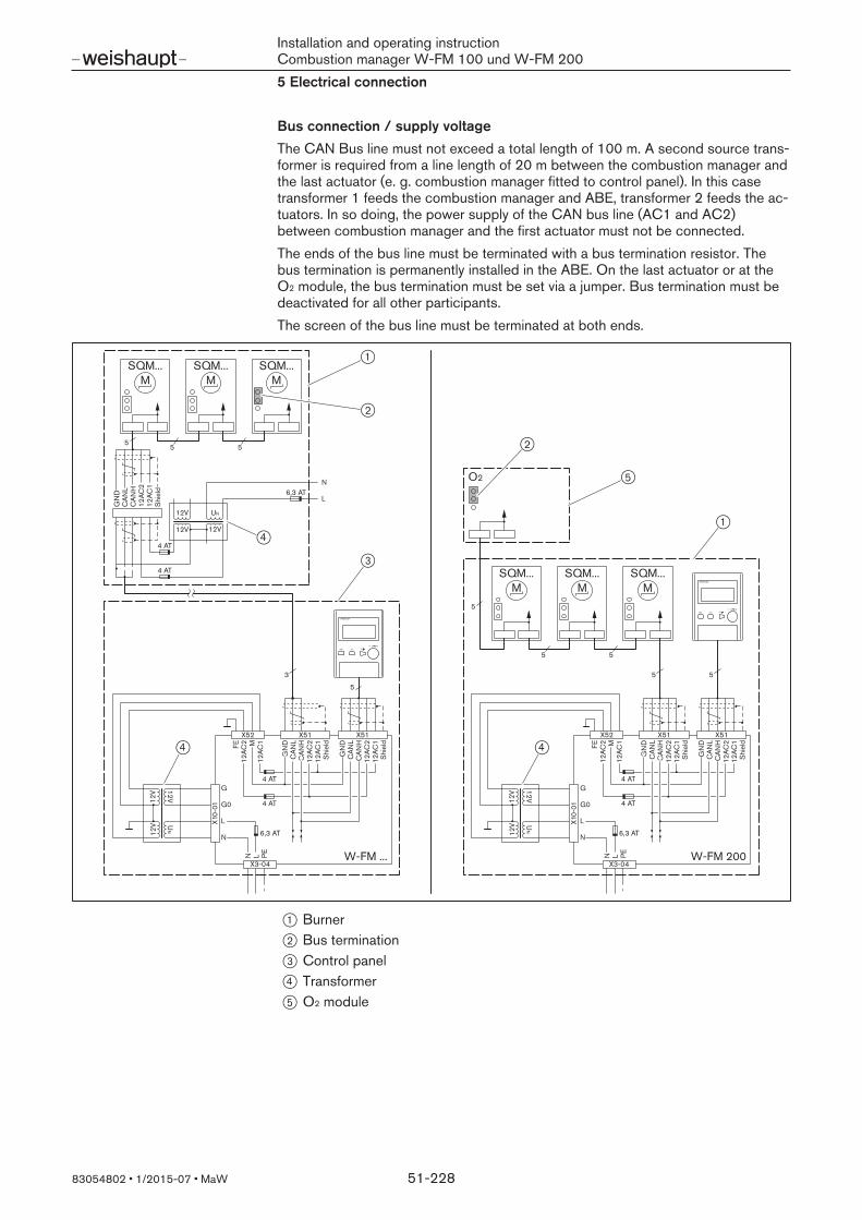
Installation and operating instructionCombustion manager W-FM 100 und W-FM 2005 Electrical connection
83054802 1/2015-07 MaW 51-228
Bus connection / supply voltageThe CAN Bus line must not exceed a total length of 100 m. A second source trans-former is required from a line length of 20 m between the combustion manager andthe last actuator (e. g. combustion manager fitted to control panel). In this casetransformer 1 feeds the combustion manager and ABE, transformer 2 feeds the ac-tuators. In so doing, the power supply of the CAN bus line (AC1 and AC2)between combustion manager and the first actuator must not be connected.The ends of the bus line must be terminated with a bus termination resistor. Thebus termination is permanently installed in the ABE. On the last actuator or at theO2 module, the bus termination must be set via a jumper. Bus termination must bedeactivated for all other participants.The screen of the bus line must be terminated at both ends.
12V
12V U
N
12V
X10-
01
G
G0
L
N
X52
FE12
AC2 M
12AC
1
GN
D
12AC
212
AC1
Shi
eld
X51 X51
CA
NL
CA
NH
GN
DC
AN
LC
AN
H12
AC2
12AC
1S
hiel
d
5
3
X3-04
N L PE W-FM ...
GN
D
12AC
212
AC1
CA
NL
CA
NH
5
Shi
eld
12V
12V
UN
12V
SQM...M
SQM...M
SQM...M
55
N
L
12V
12V U
N
12V
X10-
01
G
G0
L
N
X52
FE12
AC2 M
12AC
1
GN
D
12AC
212
AC1
Shi
eld
X51 X51
CA
NL
CA
NH
GN
DC
AN
LC
AN
H12
AC2
12AC
1S
hiel
d
SQM...M
SQM...M
SQM...M
55
5
55
O2
X3-04
N L PE W-FM 200
4 AT
4 AT
4 AT
4 AT
6,3 AT
4 AT
4 AT
6,3 AT
6,3 AT
1
2
4
3
4 4
1
5
2
1 Burner2 Bus termination3 Control panel4 Transformer5 O2 module

Installation and operating instructionCombustion manager W-FM 100 und W-FM 2005 Electrical connection
83054802 1/2015-07 MaW 52-228
Display and operating unit (ABE)The ABE is equipped with 3 interfaces.
CAN (X70): CAN Bus connection to the combustion managerCOM 1 (X71): RS-232 for PC connectionCOM 2 (X72): RJ45 connection building management system via Bus interface
The COM interfaces can not be used at the same time
1 2 3 4 5
6 7 8 9
18
CAN
X70
COM 2
X72
1 2 3 4 5
6 7 8 9
COM 1
X71
PIN CAN (X70) COM 1 (X71) COM 2 (X72)1 - - TXD2 CAN L RXD -3 GND TXD RXD4 VAC 2 - GND5 - GND U 16 - - GND7 CAN H - U 28 VAC 1 - -

Installation and operating instructionCombustion manager W-FM 100 und W-FM 2005 Electrical connection
83054802 1/2015-07 MaW 53-228
Connect burner / fan motor, pump stationThe motor must be protected against thermal overload and short circuit. The use ofa motor protection switch is recommended.
Open terminal box on motor.Connect voltage supply to wiring diagram enclosed, observe motor rotation.
Variable speed drive (optional)If the frequency converter is located on the motor, the cable to the frequency con-verter is not screened.If the frequency converter is separate the control line and the motor connectionmust be screened.
Apply screen to the designated screen clamp on frequency converter.Use screen cable glands (metal) on the burner.
Connect gas valve trainObserve wiring diagram.
Connect double gas valve (plug K32 / Y2).Solenoid coil on W-MF or DMVActuator on VGD.
Connect limit switch for valve lift monitoring (plug S33 / S35), only with VGD.Connect ignition gas valve (plug K31 / Y1).Connect low gas pressure switch (plug B31 / F11).Connect valve proving gas pressure switch (plug B32 / F12).If required, connect high gas pressure switch (plug B33 / F33).Connect connection cable to burner (use cable entry W-FM).

Installation and operating instructionCombustion manager W-FM 100 und W-FM 2005 Electrical connection
83054802 1/2015-07 MaW 54-228
Connect O2 sensorThe O2 sensor is connected to the O2 module (accessory).Connect signal cable (3 x 2 x 0.25 mm2) twisted in pairs to X81. Fit the screensingle-sided to the screen clamp of the O2 module, cable length maximum 10 m.Connect separate cable (3 x 0.75 mm2) for sensor heating to the pulsedoutput X89-2:Q4/Q5.
23
X81
456
1
QG
O...
B1
M
B2
M
G2
U3
GND
23 X8
9-21
QG
O...PE
N
L
Q5
Q4
Q5Q4
G2M
MB1
U3
B2
PLL...QGO...

Installation and operating instructionCombustion manager W-FM 100 und W-FM 2006 Operation
83054802 1/2015-07 MaW 55-228
6 Operation
6.1 Operating interface
6.1.1 Operating panel
Display and operating unit (ABE)
1
5
4 3
2
1 4 line display with scroll function2 Dial knob to scroll through menus and/or to alter values3 [ENTER] key for selection4 [esc] key to return or abort5 [info] key to return to operating display
OFF functionPress [ENTER] and [esc] simultaneously.Immediate lockout.The lockout is stored in the fault history.

Installation and operating instructionCombustion manager W-FM 100 und W-FM 2006 Operation
83054802 1/2015-07 MaW 56-228
6.1.2 DisplayThe ABE is equipped with a 4 line display with 16 characters per line. The dialknob is used to scroll through the display, the cursor 1 indicates the position se-lected.
1
Normal operationStatus/ResetFault historyLockout history
Operating display##
Normal operationStatus/ResetFault historyLockout history
The [info] key is used to jump from any menu level to theoperating display menu. The [esc] key is used to return thedisplay to the menu point previously used.
Menu level 1##
Operating displayOperationManual operation Param & Display
The [esc] key is used to leave any position and to go backall the way to menu level 1 [ch. 6.3].
Fault displayDuring a fault condition, the display alternately shows the shutdown behaviour andthe fault diagnosed as a plain text display.##
Lockout
Air pressure isoff
The combustion manager is in lockout. Once the fault hasbeen rectified, the combustion manager has to be reset forrestart [ch. 9.1].
##
Safetyshutdown
Safety loopis open
The combustion manager initiates a safety shutdown. The burner restarts automatically once the fault conditionhas been rectified.

Installation and operating instructionCombustion manager W-FM 100 und W-FM 2006 Operation
83054802 1/2015-07 MaW 57-228
6.2 Displaying and adjusting parametersCall up menu level 1
Normal operationStatus/ResetFault historyLockout history
Operating displayOperationManual operationParam & Display
Press [esc] key until menu level 1 is displayed.
Navigating through the level
UpdatingEnter PWTÜV Test
Operating displayOperationManual operationParam & Display
Turn dial knob.Cursor switches to the next menu point.
If a level has more than 4 menu points, the display scrolls up and down.
One level lowerOperating displayOperationManual operationParam & Display
Boiler setpointUser MaxloadFuelDate/Time
Press [ENTER] key.
One level higher
Boiler setpointUser MaxloadFuelDate/Time
Operating displayOperationManual operationParam & Display
Press [esc] key.
Change valueAuto/Manuel/OffTimeSwitchOffBehProgramStop
Program stopCurr: deactivatedNew: 36 Ignpos
Press [ENTER] key.Selected parameter is displayed.Turn dial knob.New value is displayed.
Save valueAuto/Manuel/OffTimeSwitchOffBehProgramStop
Program stopCurr: deactivatedNew: 36 Ignpos
Press [ENTER] key.The value changed is applied and saved.
Do not accept value:Press [esc] without first confirming with [ENTER] key.Exit parameter without changing the value.

Installation and operating instructionCombustion manager W-FM 100 und W-FM 2006 Operation
83054802 1/2015-07 MaW 58-228
6.2.1 Password
Enter passwordHE password: 9876Select Enter PW in menu level 1 and press the [ENTER].Select Access with HE and press [ENTER].Set first character using the dial knob and confirm with [ENTER].A star appears and the cursor moves to the next position.Repeat procedure until the password has been entered.Confirm password with [ENTER].Display changes to menu level 1.
Enter PWTÜV Test
Manual operationParam & DisplayUpdatingEnter PW
Access without PWAccess with HEAccess with OEMAccess with SBT
EnterPassword:9876••••
Deactivating passwordIf no key is activated for 120 minutes, the combustion manager automatically deac-tivates the password and blocks the password level.
Select Deactivate PW in menu level 1 and press [ENTER].The display shows Password has been deactivated.Press [esc] key.Display changes to menu level 1.
Operating displayOperationManual operationParam & Display
Param & DisplayUpdatingEnter PWDeactivate PW
Password hasbeen deactivated

Installation and operating instructionCombustion manager W-FM 100 und W-FM 2006 Operation
83054802 1/2015-07 MaW 59-228
6.3 Menu structureValues in the square brackets show the factory setting.
Operating display##
Normal operation Status/ResetFault historyLockout historyAlarm act/deact
##
Operation##
Boiler setpointSetpoint W1Setpoint W2
##
Load limitABUserMaxLoadMod [100 %] UserMaxLoadStg [S3]
##
FuelCurrentFuel FuelSelect
##
Date/TimeDisplay the clock
##
Date Time Weekday
Set the clockDate Time Weekday
##
Hours runGas operation OilStage1/Mod OilStage2 OilStage3 TotalHoursReset TotalHours SystemOnPower
##
StartCounterGasStartCount OilStartCount TotalStartCountR TotalStartCount
##
Fuel meter(1
Curr Flow Rate Volume Gas Volume Oil Volume Gas R Volume Oil R Reset DateGas Reset DateOil
##
Number of lockouts##
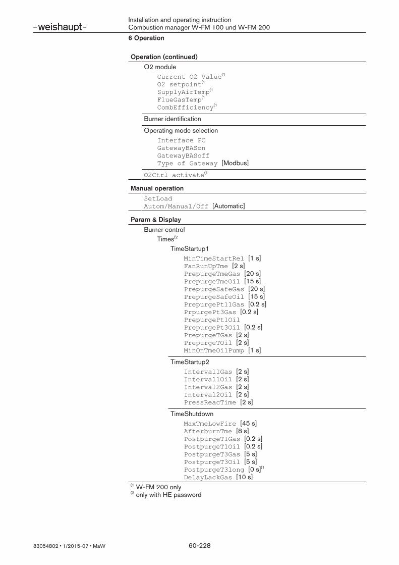
Installation and operating instructionCombustion manager W-FM 100 und W-FM 2006 Operation
83054802 1/2015-07 MaW 60-228
Operation (continued)##
O2 moduleCurrent O2 Value(1 O2 setpoint(1 SupplyAirTemp(1 FlueGasTemp(1 CombEfficiency(1
##
Burner identification##
Operating mode selectionInterface PC GatewayBASon GatewayBASoff Type of Gateway [Modbus]
##
O2Ctrl activate(1##
Manual operation##
SetLoad Autom/Manual/Off [Automatic]
##
Param & Display##
Burner controlTimes(2
TimeStartup1MinTimeStartRel [1 s]FanRunUpTme [2 s]PrepurgeTmeGas [20 s]PrepurgeTmeOil [15 s] PrepurgeSafeGas [20 s]PrepurgeSafeOil [15 s]PrepurgePtl1Gas [0.2 s]PrpurgePt3Gas [0.2 s]PrepurgePt1Oil PrepurgePt3Oil [0.2 s]PrepurgeTGas [2 s]PrepurgeTOil [2 s] MinOnTmeOilPump [1 s]
##
TimeStartup2Interval1Gas [2 s]Interval1Oil [2 s]Interval2Gas [2 s]Interval2Oil [2 s]PressReacTime [2 s]
##
TimeShutdownMaxTmeLowFire [45 s]AfterburnTme [8 s] PostpurgeT1Gas [0.2 s] PostpurgeT1Oil [0.2 s] PostpurgeT3Gas [5 s] PostpurgeT3Oil [5 s]PostpurgeT3long [0 s](1 DelayLackGas [10 s]
##
(1 W-FM 200 only (2 only with HE password

Installation and operating instructionCombustion manager W-FM 100 und W-FM 2006 Operation
83054802 1/2015-07 MaW 61-228
Param & Display (continued)##
Times in generalAlarmDelay [35 s] DelayStartPrev [35 s] PostpurgeLockout [0.2 s] MaxTmeStartRel [120 s]
##
ConfigurationConfigGeneral(2
AlarmStartPrev [deactivated]StandbyError [deactivated]NormDirectStart[NormalStart] OilPumpCoupling IgnOilPumpStart ForcedIntermit [activated] Skip PrepurgeGas [deactivated] ContinuousPurge [deactivated]
##
ConfigIn/output(2
RotSpeed PS on(1 [80] RotSpeed PS off(1 [50]Config X503 [LMV5x hrs]Start/PSValve
##
ConfigFlamDetReacExtranLight [Startblock] FlameSignal
##
RepetCounter(2
LossOfFlame [2] HeavyOil [3] StartRelease [10] SafetyLoop [16]
##
ProductIDASN ProductionDate SerialNumber ParamSet Code ParamSet Vers
##
SW Version##
Ratio controlSettingGas / Oil(2
SpecialPositionsHomePos PrepurgePos IgnitionPos PostpurgePos ProgramStop [deactivated] ResetIgnitPos
##
CurveParams##
LoadLimitsMinLoad [0 %] MaxLoad [100 %]
##
(1 W-FM 200 only (2 only with HE password

Installation and operating instructionCombustion manager W-FM 100 und W-FM 2006 Operation
83054802 1/2015-07 MaW 62-228
Param & Display (continued)##
Load mask outLoadMaskLowLimit [0 %]LoadMaskHighLim [0 %]
##
FC(1 [activated]StartPoint Op [1]
##
Autom/Manual/Off [Automatic]##
Times(2
OperRampMod OperRampStage TimeNoFlame
##
ShutdownBehav(2 [Rest pos]ProgramStop(2 [deactivated]
##
O2Contr/Alarm(1
Gas/Oil settingsOperating mode (2
O2 trim(2##
O2 monitor(2
O2 Alarm O2 MaxValue [15] NumMinUntilDeact [1]
##
Controller parameterPI LowFireAdaptPtNo(2 [2] O2CtrlThreshold(2 [0 %] LoadCtrlSuspend(2 [5 %]O2ModOffset(2 [0 %] Type Air Change(2 [like theory] O2MaxManVariable(2 [35%]O2MinManVariable(2 [-35%]
##
StartmodeO2InitOffset(2 [0 %]NoTauSuspend(2 [10]Adjust. Temp O2 [20 °C]
##
Type of Fuel(2Fuel user-def(2
V_LNmin V_afNmin V_atrNmin A2 B/1000
##
COx(2
OptgMode COx Gas [deactivated]OptgMode COx Oil [deactivated]Time COx alarm [20 s]
##
(1 W-FM 200 only (2 only with HE password
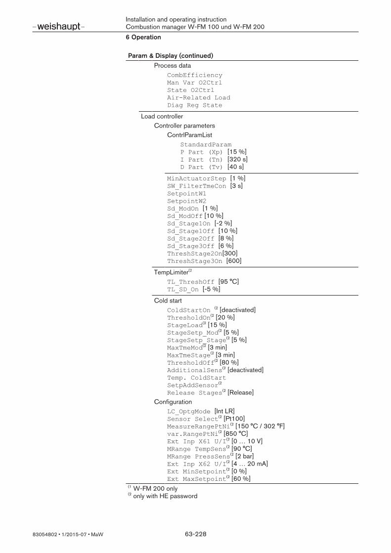
Installation and operating instructionCombustion manager W-FM 100 und W-FM 2006 Operation
83054802 1/2015-07 MaW 63-228
Param & Display (continued)##
Process dataCombEfficiency Man Var O2Ctrl State O2Ctrl AirRelated Load Diag Reg State
##
Load controllerController parameters
ContrlParamListStandardParam P Part (Xp) [15 %] I Part (Tn) [320 s] D Part (Tv) [40 s]
##
MinActuatorStep [1 %]SW_FilterTmeCon [3 s]SetpointW1 SetpointW2 Sd_ModOn [1 %]Sd_ModOff [10 %]Sd_Stage1On [-2 %]Sd_Stage1Off [10 %] Sd_Stage2Off [8 %] Sd_Stage3Off [6 %]ThreshStage2On[300] ThreshStage3On [600]
##
TempLimiter(2
TL_ThreshOff [95 °C] TL_SD_On [-5 %]
##
Cold startColdStartOn (2 [deactivated]ThresholdOn(2 [20 %] StageLoad(2 [15 %] StageSetp_Mod(2 [5 %]StageSetp_Stage(2 [5 %] MaxTmeMod(2 [3 min]MaxTmeStage(2 [3 min]ThresholdOff(2 [80 %]AdditionalSens(2 [deactivated]Temp. ColdStartSetpAddSensor(2
Release Stages(2 [Release]Configuration
LC_OptgMode [Int LR]Sensor Select(2 [Pt100]MeasureRangePtNi(2 [150 °C / 302 °F]var.RangePtNi(2 [850 °C]Ext Inp X61 U/I(2 [0 … 10 V]MRange TempSens(2 [90 °C]MRange PressSens(2 [2 bar]Ext Inp X62 U/I(2 [4 … 20 mA]Ext MinSetpoint(2 [0 %]Ext MaxSetpoint(2 [60 %]
##
(1 W-FM 200 only (2 only with HE password

Installation and operating instructionCombustion manager W-FM 100 und W-FM 2006 Operation
83054802 1/2015-07 MaW 64-228
Param & Display (continued)##
Analogue output(2
OutValuSelection [Load]CurrMod 0/4mA [4 … 20 mA]Scale20mA perc [100 %] Scale20mA temp [850 °C]Scale20mA press [2 bar]Scale20mA angle [90°] Scale 0/4mA [0 %]
##
AdaptionStartAdaption AdaptionLoad [100 %]
##
SW Version##
ABETimes
Sum/WinterTime[Automatic]Time EU/US
##
Language DateFormat PhysicalUnits
##
eBUSAddress [1] SendCycleBU [30 s]
##
ModbusAddress [1] Baud rate [19200 bit/s] Parity [none] Timeout [30 s] Local / Remote Remote Mode W3
##
Display contrast##
ProductIDASN ProductionDate SerialNumber ParamSet Code ParamSet Vers
##
SW Version##
ActuatorsAddressing(2
1 AirActuator 2 GasActuator (Oil) 3 OilActuator 4 AuxActuator 5 AuxActuator2(1 6 AuxActuator3
##
Rotation direction(2
DeleteCurves##
(1 W-FM 200 only (2 only with HE password

Installation and operating instructionCombustion manager W-FM 100 und W-FM 2006 Operation
83054802 1/2015-07 MaW 65-228
Param & Display (continued)##
ProductID1 AirActuator 2 GasActuator (Oil) 3 OilActuator 4 AuxActuator 5 AuxActuator2(1 6 AuxActuator3
##
SW Version1 AirActuator 2 GasActuator (Oil) 3 OilActuator 4 AuxActuator 5 AuxActuator2(1 6 AuxActuator3
##
VSD module(1
ConfigurationReleasecontct.VSD(2 [closed]
##
SpeedNum Puls per R(2 [3]Standardisation(2
StandardisedSp(2
Absolute SpeedSetpoint Output(2 [4 … 20 mA]
##
Fuel meter(2
PulseValueGas [1]PulseValueOil [1]
##
Process dataMax Stat Dev Max Dyn Dev NumDev >0.3% NumDev >0.5% Absolute Speed
##
Product identificationASN ProductionDateSerialNumber ParamSet Code ParamSet Vers
##
SW Version##
O2 module(1
Configuration(2
O2 Sensor [no sensor]O2SensServTim [0]O2SensServTimRes SupAirTempSens [no sensor]FlueGasTempSens [no sensor]MaxTempFlGasGas [300 °C]MaxTempFlGasOil [300 °C]
##
(1 W-FM 200 only (2 only with HE password

Installation and operating instructionCombustion manager W-FM 100 und W-FM 2006 Operation
83054802 1/2015-07 MaW 66-228
Param & Display (continued)##
Process DataCurrent O2 value O2 Setpoint SupplyAirTemp FlueGasTemp CombEfficiency QGO SensorTemp QGOHeatingLoad QGO Resistance
##
ProductIDProductionDate SerialNumber ParamSet Code ParamSet Vers
##
SW Version##
Flue gas recirculation(1
FGRMode [Aux3 Curve] FGRsensor [X86PtNi1000]actTmpFGRsensor ThresholdFGR Gas ThresholdFGR Gas [300 s] FGR Factor Gas [100] Operating temp Gas ThresholdFGR Oil ThresholdFGR Oil [300 s] Factor FGR Oil [100] Operation TempOil FGR MinPos FGR MaxPos Fact [10]
##
SystemConfigLC_OptgMode [IntLC]Ext Inp X62 U/I(2 [4 … 20 mA]
##
TempLimiter(2
TL_Thresh_Off [95 °C]TL_SD_On [-5 %] Sensor Select [Pt100] MeasureRangePtNi [150 °C / 302 °F]
##
O2Ctrl/LimitrGas(2 [man deact]O2Ctrl/LimitrOil(2 [man deact]LC Analog output(2 [Load]allowed Pot.diff(2 [15]
##
Hours runGasFiring OilStage1/Mod OilStage2 OilStage3 TotalHoursReset TotalHours SystemOnPower
##
(1 W-FM 200 only (2 only with HE password
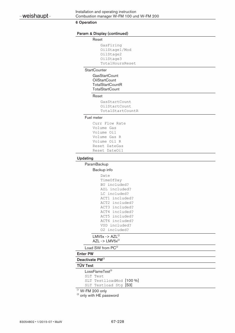
Installation and operating instructionCombustion manager W-FM 100 und W-FM 2006 Operation
83054802 1/2015-07 MaW 67-228
Param & Display (continued)##
ResetGasFiring OilStage1/Mod OilStage2 OilStage3 TotalHoursReset
##
StartCounterGasStartCount OilStartCount TotalStartCountR TotalStartCount
##
ResetGasStartCount OilStartCount TotalStartCountR
##
Fuel meterCurr Flow Rate Volume Gas Volume Oil Volume Gas R Volume Oil R Reset DateGas Reset DateOil
##
Updating##
ParamBackupBackup info
Date TimeOfDayBU included?AZL included? LC included? ACT1 included? ACT2 included? ACT3 included? ACT4 included? ACT5 included? ACT6 included? VSD included? O2 included?
##
LMV5x -> AZL(2
AZL -> LMV5x(2##
Load SW from PC(2##
Enter PW##
Deactivate PW(2##
TÜV Test##
LossFlameTest(2 SLT Test SLT TestlloadMod [100 %] SLT Testload Stg [S3]
##
(1 W-FM 200 only (2 only with HE password

Installation and operating instructionCombustion manager W-FM 100 und W-FM 2006 Operation
83054802 1/2015-07 MaW 68-228
6.4 Operation and system information
6.4.1 Normal operationOperating display Normal operation
In menu Normal operation you can switch between the standard display andthe position display.
Press [ENTER] key.Display changes.
Depending on the current operating phase, the standard display shows the follow-ing information:
Setpoint and actual valueFuel selectedCurrent operating phase (clear text and number)Fuel and air actuator positionsCurrent burner capacity and flame signal
The position display shows the following information:Actuator positionsSpeedO2 contentBurner capacity
6.4.2 Fuel selectionOperation Fuel Current fuel
Fuel selection
Current fuelThe fuel selected is shown in parameter CurrentFuel (read only).
Fuel selectionWith dual-fuel burners you can switch between oil and gas operation. A fuelchange during operation will initiate a restart.Fuel selection is possible via:
Fuel selection switch on input X4-01:1/2 [ch. 3.3.6]Parameter fuel selection (ABE)Building management system (BMS) on Bus connection
The fuel selection switch on input X4-01:1/2 has priority. Fuel selection via ABE orBMS is only possible if no signal is present at input X4-01:1/2. There is not prioritybetween ABE and BMS, the last fuel selection is valid and is retained after powerfailure.
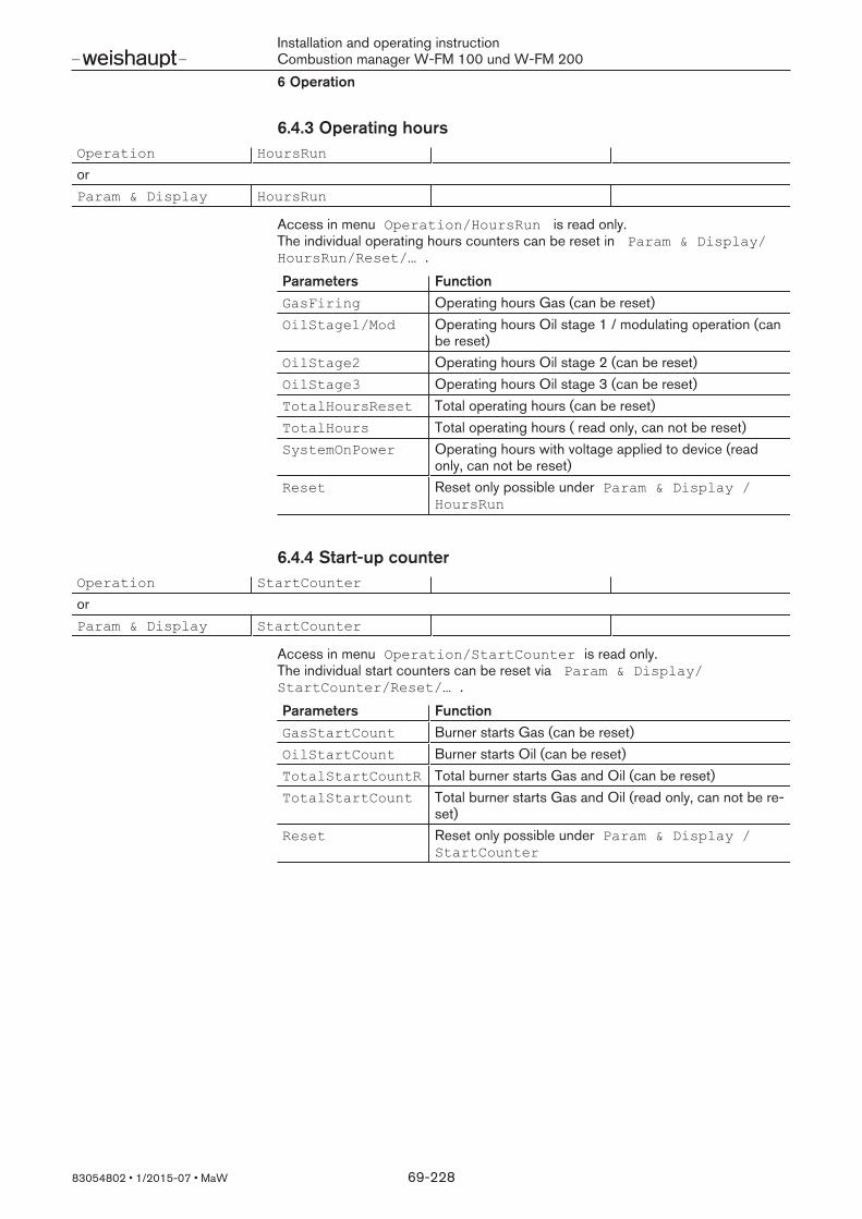
Installation and operating instructionCombustion manager W-FM 100 und W-FM 2006 Operation
83054802 1/2015-07 MaW 69-228
6.4.3 Operating hoursOperation HoursRun
orParam & Display HoursRun
Access in menu Operation/HoursRun is read only.The individual operating hours counters can be reset in Param & Display/HoursRun/Reset/… .
Parameters FunctionGasFiring Operating hours Gas (can be reset)OilStage1/Mod Operating hours Oil stage 1 / modulating operation (can
be reset)OilStage2 Operating hours Oil stage 2 (can be reset)OilStage3 Operating hours Oil stage 3 (can be reset)TotalHoursReset Total operating hours (can be reset)TotalHours Total operating hours ( read only, can not be reset)SystemOnPower Operating hours with voltage applied to device (read
only, can not be reset)Reset Reset only possible under Param & Display /
HoursRun
6.4.4 Start-up counterOperation StartCounter
orParam & Display StartCounter
Access in menu Operation/StartCounter is read only.The individual start counters can be reset via Param & Display/StartCounter/Reset/… .
Parameters FunctionGasStartCount Burner starts Gas (can be reset)OilStartCount Burner starts Oil (can be reset)TotalStartCountR Total burner starts Gas and Oil (can be reset)TotalStartCount Total burner starts Gas and Oil (read only, can not be re-
set)Reset Reset only possible under Param & Display /
StartCounter
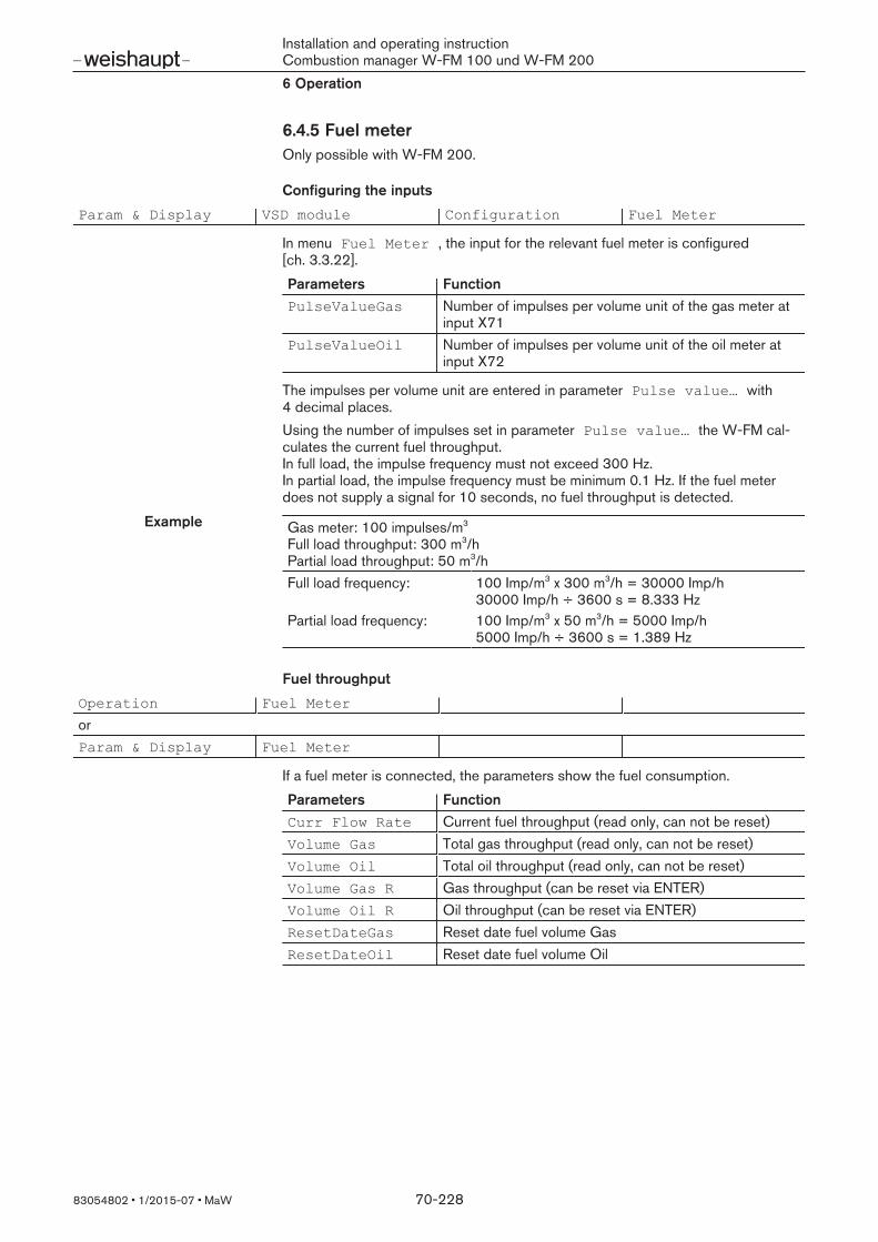
Installation and operating instructionCombustion manager W-FM 100 und W-FM 2006 Operation
83054802 1/2015-07 MaW 70-228
6.4.5 Fuel meterOnly possible with W-FM 200.
Configuring the inputs
Param & Display VSD module Configuration Fuel Meter
In menu Fuel Meter , the input for the relevant fuel meter is configured[ch. 3.3.22].
Parameters FunctionPulseValueGas Number of impulses per volume unit of the gas meter at
input X71PulseValueOil Number of impulses per volume unit of the oil meter at
input X72
The impulses per volume unit are entered in parameter Pulse value… with4 decimal places.Using the number of impulses set in parameter Pulse value… the W-FM cal-culates the current fuel throughput.In full load, the impulse frequency must not exceed 300 Hz.In partial load, the impulse frequency must be minimum 0.1 Hz. If the fuel meterdoes not supply a signal for 10 seconds, no fuel throughput is detected.
Example##
Gas meter: 100 impulses/m3
Full load throughput: 300 m3/hPartial load throughput: 50 m3/h
##
Full load frequency: 100 Imp/m3 x 300 m3/h = 30000 Imp/h30000 Imp/h ÷ 3600 s = 8.333 Hz
Partial load frequency: 100 Imp/m3 x 50 m3/h = 5000 Imp/h5000 Imp/h ÷ 3600 s = 1.389 Hz
##
Fuel throughput
Operation Fuel Meter
orParam & Display Fuel Meter
If a fuel meter is connected, the parameters show the fuel consumption.
Parameters FunctionCurr Flow Rate Current fuel throughput (read only, can not be reset)Volume Gas Total gas throughput (read only, can not be reset)Volume Oil Total oil throughput (read only, can not be reset)Volume Gas R Gas throughput (can be reset via ENTER)Volume Oil R Oil throughput (can be reset via ENTER)ResetDateGas Reset date fuel volume GasResetDateOil Reset date fuel volume Oil

Installation and operating instructionCombustion manager W-FM 100 und W-FM 2006 Operation
83054802 1/2015-07 MaW 71-228
6.4.6 Number of lockoutsOperation LockoutCounter
The parameterLockoutCounter shows the number of faults with lockout sincecommissioning (can not be reset).
6.4.7 Flame signalParam & Display BurnerControl Configuration ConfigFlameDet FlameSignal
The parameter FlameSignal shows the current flame signal [ch. 3.3.15].
6.4.8 Product identificationParam & Display BurnerControl ProductID
orParam & Display AZL ProductID
orParam & Display Actuators ProductID
orParam & Display VSD module ProductID
orParam & Display O2 module ProductID
In menu ProductID the following information is displayed for all componentsselected:
ASN (type description)Production dateIdentification numberCustomer code parametersVersion parameters
6.4.9 Software versionParam & Display BurnerControl SW Version
orParam & Display LoadController SW Version
orParam & Display AZL SW Version
orParam & Display Actuators SW Version
orParam & Display VSD module SW Version
orParam & Display O2 module SW Version
In parameter SW Version the software version of the selected components isshown.
6.4.10 Burner identificationOperation BurnerID

Installation and operating instructionCombustion manager W-FM 100 und W-FM 2006 Operation
83054802 1/2015-07 MaW 72-228
The parameter BurnerID shows the burner specific serial number. The burner identification serves as copy protection. Burner specific data in thememory of the ABE can not be transferred to another W-FM.If a W-FM is delivered without burner identification and the backup copy from theABE is installed, the W-FM adopts the burner identification of the backup copy[ch. 6.16.1].

Installation and operating instructionCombustion manager W-FM 100 und W-FM 2006 Operation
83054802 1/2015-07 MaW 73-228
6.5 Setting the display
6.5.1 Setting the languageParam & Display AZL Language
The language for the display can be set in parameter Language . If the language required is not available, the display and operating unit (ABE) withthe relevant group of languages should be used.
Group of languages (ABE) LanguagesWestern Europe 1 English, German, French, Italian, Spanish, Por-
tugueseWestern Europe 2 English, Dutch, Danish, Swedish, Norwegian, Fin-
nishEastern Europe 1 English, Polish, Hungarian, Czech, Croatian, Slove-
nianEastern Europe 2 English, German, Russian, Bulgarian, Turkish, Ru-
manian
6.5.2 Set contrastParam & Display AZL Display Contrast
The contrast of the display can be changed and saved using parameter DisplayContrast .If the operating display is in normal operation, the contrast can be changed usingthe dial knob of the ABE.
Press and hold [Enter].Set the contrast using the dial knob.The setting will remain until the power supply is interrupted

Installation and operating instructionCombustion manager W-FM 100 und W-FM 2006 Operation
83054802 1/2015-07 MaW 74-228
6.5.3 Date/Time
Display date and time
Operation Date/TimeOfDay DisplayClockSet time
DateTimeOfDayWeekday
The date, time and weekday can be displayed in menu DisplayClock.The date, time and weekday are set using SetClock.
Summer/Winter time
Param & Display AZL Times Sum/WinterTimeTime EU/US
Parameter Sum/WinterTime is used to select manual or automatic changeoverfrom summertime to wintertime.Parameter Time EU/US is used to select the European or American summer-time or wintertime.
Date format
Param & Display AZL DateFormat
Parameter DateFormat is used to select the date format DD.MM.YY orYY.MM.DD.
6.5.4 UnitsParam & Display AZL PhysicalUnits
Parameter PhysicalUnits is used to select the formats °C / bar or °F / psi. All relevant values will be displayed and adjusted in the unit selected.
Installation and operating instructionCombustion manager W-FM 100 und W-FM 2006 Operation
83054802 1/2015-07 MaW 75-228
6.6 Interfaces
6.6.1 Select interfacesOperation OptgModeSelect InterfacePC
Gateway BASonGateway BASoffType of Gateway
Menu OptgModeSelect is used to select the serial interface in the operatingand display unit (COM 1 or COM 2) [ch. 5].The COM interfaces can not be used at the same time.
Interface for PC (COM 1)The combustion manager can be programmed and operated via PC-Tool (Soft-ware: ACS450). The display and operating unit serves as interface.
Select parameter InterfacePC and confirm with [ENTER].The interface is activated until the [esc] key is used to exit from parameter InterfacePC .
Interface for building management system (COM 2)The building management system can be connected to the ABE using an externalBus interface allowing it to access the W-FM.Activating the interface:
Select parameter Gateway BASon and confirm with [ENTER].The interface in the display and operating unit (ABE) has been activated and thebuilding management system can access the W-FM. The ABE remains func-tional.
Deactivating the interface:Select parameter Gateway BASoff and confirm with [ENTER].The interface of the display and operating unit (ABE) for the building manage-ment system is deactivated. Only the ABE can access the W-FM.
Select Bus protocol:Select Bus protocol in parameter Type of Gateway and confirm with[ENTER].eBus [ch. 6.6.2]Modbus [ch. 6.6.3]Data output [ch. 6.6.4]

Installation and operating instructionCombustion manager W-FM 100 und W-FM 2006 Operation
83054802 1/2015-07 MaW 76-228
6.6.2 eBusParam & Display AZL eBus Address
SendCycleBU
For Bus communication, the interface has to be activated and the bus protocol hasto be defined.
eBus addressParameter Address defines the eBus address, which is used to communicateswith the W-FM.
Send cycleParameter SendCycleBU defines the time for the send cycle. The W-FM trans-mits its operating data to the eBus participants in the cycle set.
6.6.3 ModbusParam & Display AZL Modbus
For Bus communication, the interface has to be activated and the bus protocol hasto be defined.The display and operating unit (ABE) operates as Slave in the Modbus protocol.The RTU-Modus is used for transfer.
Modbus addressParameter Address determines the Modbus address of the display and operat-ing unit (ABE).
Baud rateParameter Baudrate determines the transfer speed. The Baud rate of the dis-play and operating unit (ABE) and the Modbus participant connected must beidentical.
ParityParameter Parity determines the type of parity protocols. The parity of the dis-play and operating unit (ABE) and the Modbus participant connected must beidentical.
Time outParameter Timout determines how long after Modbus communication fails thedisplay and operating unit (ABE) switches from Remote to Local . If building management is deactivated or the Modbus connection fails, the internalload controller of the W-FM takes over the control and the internal setpoint (W1) isactivated. Prerequisite is that the W-FM is equipped with an internal load controllerand has been configured [ch. 6.12].

Installation and operating instructionCombustion manager W-FM 100 und W-FM 2006 Operation
83054802 1/2015-07 MaW 77-228
Local / Remote
Setting Functionlocal The operating modes for the load controller via Bus Ex
tLC Bus or IntLC Bus have no influence[ch. 6.12.2]. The internal load controller takes over the control and theinternal setpoint W1 is activated.
remote Setting for load control via Bus [ch. 6.12.2].If the operating mode ExtLC Bus has been selected,the building management system determines the load. If operating mode IntLC Bus has been selected, thebuilding management system determines the setpoint.If Modbus communication fails, the W-FM automaticallychanges into local mode. When communication isrestored, the mode has to be set to remote either viathe ABE or via Modbus signal.
Remote modeParameter Remote mode is read only, the setting is made via Modbus (buildingmanagement system).
Setting FunctionAuto Setpoint W3 is determined by the building management
system.On Load is determined by the building management system.Off The internal load controller takes over the control.
External setpoint W3Parameter W3 is read only, the setting is made via Modbus (building managementsystem).
6.6.4 Trending dataOperation OptgModeSelect Type of Gateway Data output
In Bus protocol Data output the interface COM 2 sends trending data for datarecording.Interface configuration in menu Modbus is required for data output [ch. 6.6.3].Data recording is not possible for diagnostic purposes during servicing and withoutperipherals and software.

Installation and operating instructionCombustion manager W-FM 100 und W-FM 2006 Operation
83054802 1/2015-07 MaW 78-228
6.7 Manual / Automatic / OffManualOperation SetLoad
Autom/Manual/Off
orParam & Display RatioControl Autom/Manual/Off
Operating modeParameter Autom/Manual/Off determines the operating mode. In Remote op-eration the parameter is read only and can not be altered [ch. 6.6.3].
Setting FunctionAutomatic The burner starts if there is a heat demand at in-
put X5-03:1. The load controller determines the burner capacity.
Manuel The burner starts if there is a heat demand at in-put X5-03:1. Parameter SetLoad determines the burner capacity.
Burner Off Burner drives to or remains in Standby (Phase 12). Amessage, that the W-FM is set to Burner Off inmanual operation does not appear.
Target loadLoad, to which the burner drives in Manuel operating mode. In modulating operation, the target load can be set within the load limits [ch. 6.9.7]. In multi-stage operation, one of the stages can be selected as the target load.

Installation and operating instructionCombustion manager W-FM 100 und W-FM 2006 Operation
83054802 1/2015-07 MaW 79-228
6.8 Burner control
6.8.1 TimesParam & Display BurnerControl Times TimesStartup1
TimesStartup2 TimesShutdown TimesGeneral
TimeStartup1
Time Parameters FunctionStart release MinTimeStartRel Minimum residence time in phase 21.
The W-FM remains at least the time set in phase 21,even if the start criteria have already been met.
Fan run-up time FanRunupTime Residence time in phase 22. Once this time has elapsed the burner drives to pre-purge position.
Pre-purge PrepurgeTmeGas PrepurgeTmeOil
Time from reaching the pre-purge position until driving toignition position (phase 30 to 34).
PrepurgeSafeGas PrepurgeSafeOil
Pre-purge time after the following occurrences:Lockout or safety shutdownPower failureStandby longer than 24h
PrepurgePt1GasPrepurgePt1Oil
Auxiliary actuator3 (FGR) remains in standby position inPhase 30 for the duration of this time.
PrepurgePt3GasPrepurgePt3Oil
Time in phase 34 during which all actuators remain inpre-purge position.
Pre-ignitionNozzle circulation
PreIgnitionTGas PreIgnitionTOil
Residence time in phase 38. Once this time has elapsed, fuel is released for ignition.On heavy oil burners without return flow temperaturesensor, nozzle circulation can be extended via PreIgnitionTOil .
Oil pump ON time MinONTmeOilPump Residence time in phase 36 (heavy oil operation only). In heavy oil operation, the time in phase 36 can be exten-ded to allow oil pressure to build-up for ignition.
TimeStartup2
Time Parameters FunctionFlame stabilisation Interval1Gas
Interval1OilResidence time in phase 44. Once this time has elapsed the burner drives to partialload.
Interval2Gas Interval2Oil
Residence time in phase 52. Once this time has elapsed the burner drives to partialload.
Pressure switch reaction time
PressReacTime Time delay in phase 40, 42 and 52. The pressure switches are interrogated in phase 40, 42and 52 by the time delay set. Prevents shutdown caused by pressure fluctuation whenopening the fuel valves.

Installation and operating instructionCombustion manager W-FM 100 und W-FM 2006 Operation
83054802 1/2015-07 MaW 80-228
TimeShutdown
Time Parameters FunctionLoad shutdown MaxTmeLowFire Residence time in phase 62.
If there is no longer a demand for heat, the W-FM re-duces the burner capacity and closes the fuel valvesafter the time set has elapsed. If partial load is reachedbefore the time has elapsed, the fuel valves close imme-diately.
Anti siphon valve AfterburnTme Residence time in phase 70. Once the time has elapsed, the anti siphon valve at out-put X6-03 closes and the actuators for air and fuel driveto post-purge position.
Post-purge time PostpurgeT1Gas PostpurgeT1Oil
Residence time in phase 74. Post-purge time 1 in phase 74 is always executed. Oncethis time has elapsed, the auxiliary actuator3 (FGR)drives to post-purge position.
PostpurgeT3Gas PostpurgeT3Oil
Residence time in phase 78. Post-purge time 3 in phase 78 is interrupted at heat de-mand. Once the time has elapsed without heat demand,the W-FM goes to Standby.
PostpurgeT3long(W-FM 200 only)
Additional residence time in phase 78. The PostpurgeT3long is added to both fuel de-pendent times PostpurgeT3Gas / Oil .
Times in general
Time Parameters FunctionAlarm delay during start pre-vention
AlarmDelay Time delay until a start prevention at heat demand is is-sued at output X3-01:2. The function Alarm during startprevention must be activated in parameterAlarmDelay.
Message start prevention DelayStartPrev Time delay until a start prevention at heat demand isshown in the display of the ABE.
Post-purge time lockout PostpurgeLockout If lockout occurs, the fan motor at output X3-01:1 runson by the time specified.
Heavy oil immediate start MaxTmeStartRel Maximum waiting time for signal at input X6-01:3.

Installation and operating instructionCombustion manager W-FM 100 und W-FM 2006 Operation
83054802 1/2015-07 MaW 81-228
6.8.2 Signalling start prevention
Alarm at start prevention
Param & Display BurnerControl Configuration ConfigGeneral AlarmStartPrev
If parameter AlarmStartPrev is activated, start prevention is also signalled atoutput X3-01:2 [ch. 3.4.1].
Start prevention in Standby
Param & Display BurnerControl Configuration ConfigGeneral Standby Error
If parameter Standby error is activated, faults are also recognised as startprevention in Standby and are displayed in the ABE.
6.8.3 Normal or direct startParam & Display BurnerControl Configuration ConfigGeneral NormDirectStart
Start prevention at heat demand during shutdown in phase 78.
Normal startIf NormalStart is activated, the fan switches off and the burner only starts aftera home run in phase 10.
Direct startIf DirectStart is activated the fan continues to run and the W-FM jumps viaphase 79 to phase 24. In conjunction with an air pressure switch direct start is only possible with a releasevalve at output X4-03 [ch. 3.4.4]. In menu Config input /output the para-meter Start/PSvalve must therefore be set to PS Reli_Inv .
Installation and operating instructionCombustion manager W-FM 100 und W-FM 2006 Operation
83054802 1/2015-07 MaW 82-228
6.8.4 Oil pumpParam & Display BurnerControl Configuration ConfigGeneral OilPumpCoupling
IgnOilPumpStart
Control of oil pump and switch on point of pre-ignition in oil operation [ch. 3.4.3].
Magnetic coupling / separate oil pumpFor burners with magnetic coupling or separate oil pump:
Set parameter OilPumpCoupling to Magnetcoupl.Set parameter IgnOilPumpStart to On in Ph38 .
Direct couplingFor burners with oil pump coupled directly to the burner motor.
Set parameter OilPumpCoupling to Direct coupl .The long pre-ignition (on in Ph22) is automatically activated in parameterIgnOilPumpStart .
6.8.5 Forced intermittentParam & Display BurnerControl Configuration ConfigGeneral ForcedIntermit
With ForcedIntermit activated, the W-FM initiates a controlled shutdown with sub-sequent restart after 23 h 50 min uninterrupted burner operation. If the burner isnot suitable for continuous operation, forced intermittent has to be activated.
6.8.6 Pre-purge GasParam & Display BurnerControl Configuration ConfigGeneral Skip Prepur
geGas
If the parameter is activated, the W-FM skips pre-purge in gas operation (Phase 24to 34). According to EN 676 only allowed with Class A valves in conjunction withvalve proving system.Pre-purge is not skipped after:
Lockout24 h StandbyPower failureSafety shutdown due to low gas

Installation and operating instructionCombustion manager W-FM 100 und W-FM 2006 Operation
83054802 1/2015-07 MaW 83-228
6.8.7 Continuous running fanParam & Display BurnerControl Configuration ConfigGeneral ContinuousPurge
If ContinuousPurge is activated, the fan runs in each operating phase. If an air pressure switch is fitted, continuous purge is only possible with a reliefvalve at output X4-03 [ch. 3.4.4]. For this, parameter Start/PSvalve must beset to PS Reli_Inv in menu Config Input /Output.
Setting Functiondeactivated In phases 00 to 21, output X3-01:1 (fan) is not activ-
ated. In Phase 00 to 21, the frequency converter is controlledwith the idle speed (HomePosVSD) set, even if the safetycircuit / burner flange is open.
activated Output X3-01:1 (fan) and the frequency converter are al-ways activated, even if the safety circuit / burner flangeare open.
off Sloop Output X3-01:1 (fan) and the frequency converter are al-ways activated, except if the safety circuit / burner flangeare open.
deact/VSDSL In phases 00 to 21, output X3-01:1 (fan) is not activ-ated. In Phase 00 to 21, the frequency converter is controlledwith the idle speed (HomePosVSD) set, except if thesafety circuit / burner flange is open.
6.8.8 Additional air pressure switchParam & Display BurnerControl Configuration Config input/
outputRotSpeed PS on RotSpeed PS off
The speed range set is monitored by an additional air pressure switch. In the OEM level, the additional air pressure switch is deactivated, the function isnot used in standard applications.
Parameters FunctionRotSpeed PS on The additional air pressure switch must supply an ON
signal above the speed set.RotSpeed PS off The additional air pressure switch must supply an OFF
signal below the speed set.

Installation and operating instructionCombustion manager W-FM 100 und W-FM 2006 Operation
83054802 1/2015-07 MaW 84-228
6.8.9 Configuring input X5-03Param & Display BurnerControl Configuration Config input/
outputConfig X503
Parameter Config X503 determines how the W-FM reacts to signals at in-put X5-03.
Load controller multi-stage operating modeIf a load controller is connected to input X5-03 [ch. 3.3.16], the parameter determ-ines the control of the operating stages.
Setting Input X5-03 Operating modePin 2 Pin 3 two stage three stage
LMV2/3 inv (Standard)
0 0 Stage 1 Stage 11 0 Stage 1 Stage 20 1 Stage 2 Stage 31 1 Stage 2 Stage 3
LMV5x std(with KS40load control-ler)
0 0 Stage 1 Stage 11 0 Stage 1 Stage 10 1 Stage 2 Stage 21 1 Stage 2 Stage 3
LMV2/3 std(special ap-plication)
0 0 Stage 1 Stage 11 0 Stage 2 Stage 30 1 Stage 2 Stage 21 1 Stage 2 Stage 3
Deactivate O2 trim / stop in phase 36If function DeaO2/Stp36 is set in parameter Config X503 , input X5-03can be used to deactivate O2 trim or to trigger a stop function. For this setting,parameter LC_OptgMode must not be set to ExtLC X503 .
Input FunctionPin 2 (X5-03) Mains voltage input at X5-03:2 deactivates O2 trim and the
W-FM 200 operates to the compound curves. The function O2
alarm remains activated.Pin 3 (X5-03) If no mains voltage is applied to input X5-03:3, the burner stops
at the start in phase 36. If the stop function is not used in con-junction with the O2 deactivation, fit a bridge at input X5-03between terminals 3 and 4.
Deactivate O2 trim via operating modeIf the function AutoDeactO2is set in parameter Config X503 and if mainsvoltage is applied to input X5-03:2, the operating mode of the O2 controllerchanges from conAutoDeac to auto deact. The O2 controller is deactivatedand the burner operates to the compound curves. The function O2 alarm remainsactivated. No message will be shown on the display. If voltage is no longer appliedto input X5-03:2, the operating mode changes back to conAutoDeac and O2
trim is reactivated [ch. 6.10.1]. For this setting, parameter LC_OptgMode mustnot be set to ExtLC X503 .

Installation and operating instructionCombustion manager W-FM 100 und W-FM 2006 Operation
83054802 1/2015-07 MaW 85-228
6.8.10 Configuring output X4-03Param & Display BurnerControl Configuration Config input/
outputStart/PS valve
Parameter Start/PS valve determines if output X4-03 is used for a start sig-nal or for pressure switch relief [ch. 3.4.4].
Setting FunctionStart signal Output X4-03:3 is activated in phase 21 to 79.PS Relief Output X4-03:3 is activated in phase 79.
Function is not used.PS Reli_Inv In phase 21 and phase 79 the relief valve at out-
put X4-03:3 is de-energised and the air pressure switchis tested.
6.8.11 Extraneous lightParam & Display BurnerControl Configuration ConfigFlameDet ReacExtranLight
Parameter ReacExtranLight determines the reaction if extraneous light ispresent in Standby (Phase 12).
Setting FunctionLockout Flame signal in phase 12 triggers a lockout.Startblock A flame signal in phase 12 leads to start prevention.
6.8.12 Repetition counterParam & Display BurnerControl Configuration RepetitCounter
The parameters in menu RepetitCounter determine the number of safetyshutdowns until shutdown with lockout is initiated. Changes in the repetitioncounter are only adapted after a reset or if the voltage supply has been interrupted.
Parameters FunctionLossOfFlame Number of safety shutdowns due to missing flame signal.
Range: (1 … 2)HeavyOil Number of safety shutdowns caused by return temperat-
ure sensor for nozzle circulation not being released[ch. 3.3.10]. Range: (1 … 3 … 16(1)
StartRelease Number of start preventions with display messagesnozzle circulation [ch. 3.3.10]. Range: (1 … 10 … 16(1)
SafetyLoop Number of safety shutdowns caused by the safety circuitnot being released [ch. 3.3.2]. Range: (1 … 16(1)
€€
(1 Repetition value 16 means not limited, no shutdown with lockout is initiated.
6.9 Electronic compound
6.9.1 Actuator rampsParam & Display RatioControl Times OperatRampMod
OperatRampStageRamp
Installation and operating instructionCombustion manager W-FM 100 und W-FM 2006 Operation
83054802 1/2015-07 MaW 86-228
The ramps determine the speed of the actuators for a distance of 90°. The ramptimes must not fall below the time of the slowest actuator, see actuator name plate.
Parameters FunctionOperatRampMod Ramp time for modulating operation for phases 60 and
62. In operating position, all actuators operate at thisspeed.
OperatRampStage Ramp time for multi-stage operation for phases 60 and62. In operating position, all actuators operate at thisspeed.
Ramp Ramp time outside the operating position for modulatingand multi-stage operation. All actuators operate at thisspeed in pre-purge, ignition, post-purge and standby po-sition.
Only in conjunction with frequency converterThe ramp time of the frequency converter must be less than the ramp time set inthe W-FM (recommendation: 30 %).
6.9.2 Shutdown behaviourParam & Display RatioControl ShutdownBehav
Parameter ShutdownBehav determines the behaviour during lockout.
Setting FunctionUnchanged The actuators remain in the position they were in at the
time of the lockout.PostpurgeP If lockout occurs, the W-FM initiates a post-purge.HomePos If lockout occurs, the actuators drive to standby position.
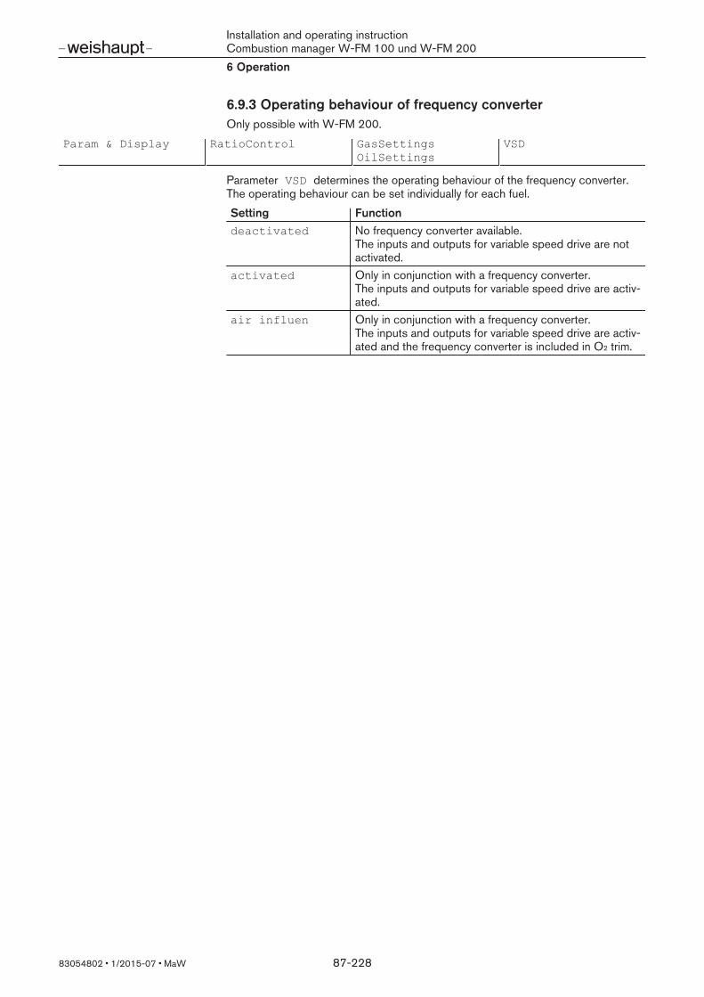
Installation and operating instructionCombustion manager W-FM 100 und W-FM 2006 Operation
83054802 1/2015-07 MaW 87-228
6.9.3 Operating behaviour of frequency converterOnly possible with W-FM 200.
Param & Display RatioControl GasSettingsOilSettings
VSD
Parameter VSD determines the operating behaviour of the frequency converter.The operating behaviour can be set individually for each fuel.
Setting Functiondeactivated No frequency converter available.
The inputs and outputs for variable speed drive are notactivated.
activated Only in conjunction with a frequency converter.The inputs and outputs for variable speed drive are activ-ated.
air influen Only in conjunction with a frequency converter.The inputs and outputs for variable speed drive are activ-ated and the frequency converter is included in O2 trim.

Installation and operating instructionCombustion manager W-FM 100 und W-FM 2006 Operation
83054802 1/2015-07 MaW 88-228
6.9.4 SpecialPositionsParam & Display RatioControl GasSettings
OilSettingsSpecialPositions
Home PosPrepurgePosIgnitionPosPostpurgePosProgramStopResetIgnitPos
If the burners is in operating position (phases 60 and 62), the actuators and thespeed are driven by the compound curves. Outside of the operating position, theactuators and the speed are driven according to the SpecialPositions . In the special positions, the actuators can be set independently. Special positions are fuel specific and must be set separately for each fuel on dualfuel burners.
Setting Actuator…PosGas: Gas butterfly valve…PosOil: Oil quantity regulator…PosAir: Air dampers…PosAux1: Adjustable mixing head…PosAux2: Auxiliary actuator for special applications (W-FM 200
only)…PosAux3: Auxiliary actuator for special applications,
damper for flue gas recirculation (W-FM 200 only)…PosVSD: VSD (only in conjunction with frequency converter,
W-FM 200)
Standby positionsParameter HomePos determines the positions for phases 00 to 22. If continuousrunning fan is activated, only the fuel actuators drive to standby position inphases 00 to 22, the air influencing actuators remain in the post-purge position.
Pre-purge positionParameter PrepurgePos determines the positions of the air influencing actuat-ors for pre-purge in phases 30 to 34. The exception is the auxiliary actuator3 (fluegas recirculation), which only drives to pre-purge position from phase 32.
Ignition positionParameter IgnitionPos determines the positions for the ignition process inphases 36 to 54.Individual ignition positions can be deleted in parameter ResetIgnitPos . If arelevant ignition position is not defined, the W-FM initiates a start prevention atheat demand. Se installation and operating manual of burner for the ignition posi-tion.

Installation and operating instructionCombustion manager W-FM 100 und W-FM 2006 Operation
83054802 1/2015-07 MaW 89-228
Post-purge positionParameter PostpurgePos defines the positions for post-purge in phases 74to 78. The exception is auxiliary actuator 3 (flue gas recirculation), which only drivesto the post-purge position after phase 76. The speed PostpurgePosVSD must not be set below 10 %.
Program stopUsing parameter ProgramStop, the program sequence can be stopped indefined phases. Parameter ProgramStop can also be called up in menu Param& Display/RatioControl.
Setting Functiondeactivated No program stop24 PrePurgP Stop in phase 24, pre-purge position32 PrePFGR Stop in phase 32, auxiliary actuator3 in pre-purge posi-
tion36 IgnitPos Stop in phase 36, ignition position44 Interv 1 Stop in phase 44, flame signal52 Interv 2 Stop in phase 52, ignition pilot valve OFF72 PostPPos Stop in phase 72, post-purge position76 PostPFGR Stop in phase 76, auxiliary actuator3 in post-purge posi-
tion

Installation and operating instructionCombustion manager W-FM 100 und W-FM 2006 Operation
83054802 1/2015-07 MaW 90-228
6.9.5 Creating load points, modulating operationParam & Display RatioControl GasSettings
OilSettingsCurveParams Point
Man
Depending on the load signal, the W-FM controls the actuators in compound inmodulating operation. Each actuator has its own compound curve. The compoundcurves are formed from defined load points. 15 load points can be defined for thecompound curves, a minimum of 5 load points are required. On dual fuel burners,the compound curves for each fuel can be set separately. In menu Point 1,load points can be adjusted or deleted to optimise combustion. In menu Manual2 new load points are set.
Point|Load:15.0 |Fuel:10.0Manual |Air :15.0 |Aux1: 0.02
1
During initial commissioning, set load points up to full load. Once full load has beenregulated, optimise combustion in load point 1. Load point 1 must be within the ca-pacity graph and below below partial load. Now delete all load points betweenpoint 1 and full load. Starting at point 1, set new load points until full load isachieved. Optimise combustion in the current point before setting a new load point. To ensure an even speed characteristic curve, the speed of the new load pointsshould not be altered. To ensure that control is possible across the entire load range in conjunction withO2 trim point 1 must be approx. 50 % below partial load (point 2).
0
10
20
30
40
50
60
70
80
90
0 10 20 30 40 50 60 70 80 90 1000102030405060708090100
P1 P2 P3 P4 P5 P6 P7 P8 P9
2
1
4
56
7
3
1 Burner capacity in %2 Actuator position in degree of angle3 Speed in %4 Fuel Fuel5 Air damper Air6 Mixing head Aux17 Frequency converter VSD

Installation and operating instructionCombustion manager W-FM 100 und W-FM 2006 Operation
83054802 1/2015-07 MaW 91-228
Setting new load pointsSelect Manual and confirm with [ENTER].Increase burner rating using dial knob whilst observing combustion values (ex-cess air) and flame stability.Set load point using [ENTER] key if either:
the O2 content in the flue gas increases to above 7 %,the soot limit is reached,the CO content increases,the flame reaches the limit of stability.
The new load point is displayed in menu Point and can be adjusted.
Point|Load:10.0 |Fuel:10.0Manual |Air :15.0 |Aux1: 0.0
O2 XXXX
|Load:10.0|Fuel:10.0|Air :20.0|Aux1: 0.0
Manual:10.0
O2 XXXX
|Load:15.0|Fuel:14.4|Air :23.8|Aux1: 5.0
Manual:15.0
Point : 2
|Load:15.0|Fuel:14.4|Air :23.8|Aux1: 5.0
O2 XXXX
Editing load pointsSelect Point and confirm with [ENTER].Select load point using dial knob and confirm with [ENTER] key.Confirm query Change point? with [ENTER].Confirm query With start with [ENTER].The curve points can be changed and the actuators are synchronised.Select actuator using the dial knob and press [ENTER].Change values using the dial knob and confirm with [ENTER].Once combustion has been optimised, exit point using [esc] and save with[ENTER].
Point |Load:15.0|Fuel:14.4|Air :23.8|Aux1: 5.0
ManualPoint :1
|Load:10.0|Fuel:10.0|Air :20.0|Aux1: 0.0
O2 XXXX
Point : 2
|Load:15.0|Fuel:14.4|Air :23.8|Aux1: 5.0
O2 XXXX
Point : 2
|Change|point?||
ManualActuatorpositionsWith start Without startPoint
: 2|Load:15.0|Fuel:14.4|Air :23.8|Aux1: 5.0
O2 XXXXPoint
: 2|Load:15.0|Fuel:14.4|Air :28.5|Aux1: 5.0
O2 XXXXPoint
: 2|Load:15.0|Fuel:14.4|Air :28.5|Aux1: 5.0
O2 XXXXSave
point>ENTERcancel>ESC
Point : 2
|Load:15.0|Fuel:14.4|Air :28.5|Aux1: 5.0
O2 XXXX

Installation and operating instructionCombustion manager W-FM 100 und W-FM 2006 Operation
83054802 1/2015-07 MaW 92-228
Deleting load pointsSelect menu Point and confirm with [ENTER].Select load point using dial knob and confirm with [ENTER] key.Select Delete point? and confirm with [ENTER].Load point is deleted.Load points above this will be renumbered. The display shows the next higherload point in the current numbering. If the last load point was deleted, the actu-ator positions show XXXX .
Point |Load: 0.0|Fuel:0.0|Air :23.8|Aux1: 5.0
ManualPoint : 1
|Load:10.0|Fuel:10.0|Air :20.0|Aux1: 0.0
O2 XXXX
Point : 2
|Load:15.0|Fuel:14.4|Air :23.8|Aux1: 5.0
O2 XXXX
Point : 2
|Change|point?|delete?|
ManualPoint : 2
|Load:24.3|Fuel:22.1|Air :32.9|Aux1:27.6
O2 XXXX

Installation and operating instructionCombustion manager W-FM 100 und W-FM 2006 Operation
83054802 1/2015-07 MaW 93-228
Ratings apportionmentThe load points are automatically assigned relative to the capacity. Incorrect loaddistribution can cause operating problems during the load control.
Assign rating in % for load point to the following formula.Enter the calculated capacity for load point in Load.
Load [%] = Throughput load pointThroughput full load
100
Select Point and confirm with [ENTER].Select load point using dial knob and confirm with [ENTER] key.Confirm query Change point? with [ENTER].Confirm query With start with [ENTER].Confirm line Load with [ENTER].Calculate actual load.Set load using dial knob and confirm with [ENTER].Exit point using [esc] and save with [ENTER].
Point |Load:15.0|Fuel:14.4|Air :23.8|Aux1: 5.0
ManualPoint :1
|Load:10.0|Fuel:10.0|Air :20.0|Aux1: 0.0
O2 XXXX
Point : 2
|Load:15.0|Fuel:14.4|Air :23.8|Aux1: 5.0
O2 XXXX
Point : 2
|Change|point?||
ManualActuatorpositionsWith start Without startPoint
: 2|Load:15.0|Fuel:14.4|Air :28.5|Aux1: 5.0
O2 XXXXPoint
: 2|Load:29.3|Fuel:14.4|Air :28.5|Aux1: 5.0
O2 XXXXPoint
: 2|Load:29.3|Fuel:14.4|Air :28.5|Aux1: 5.0
O2 XXXXSave
point>ENTERcancel>ESC
Point : 2
|Load:15.0|Fuel:14.4|Air :28.5|Aux1: 5.0
O2 XXXX

Installation and operating instructionCombustion manager W-FM 100 und W-FM 2006 Operation
83054802 1/2015-07 MaW 94-228
6.9.6 Operating and switch points, multi-stage operationParam & Display RatioControl OilSettings CurveParams CurveSet
Two or three stage operation is specified depending on the burner execution. Athree stage burner can also be operated two stage with low impact start orchange-over release. The change-over behaviour between the operating stages isoptimised via separate switch on and off points.
Operating stagesBS1, BS2, BS3(1
Excess air for the relevant fuel quantity is set in the operating stages.
Switch-on points ES2, ES3(1
In the switch-on point, the air quantity for the change-over process into the nexthigher stage is set.If the switch-on point is exceeded, the solenoid valve of the next stage opens.If the switch-on point is activated directly the solenoid valve remains closed, onlythe air influencing actuators drive to the switch-on position and the flame stabilitycan be checked prior to the change-over.
Switch-off pointsAS2, AS3(1
In the switch-off point, the air quantity for the change-over process into the nextlower stage is set.If the switch-on point is not maintained, the solenoid valve of the previous stagecloses. Switch-off points must not be activated directly, as the solenoid valve ofthe previous stage remains open and only the air influencing actuators drive to theswitch off position. This leads to soot formation caused by insufficient air.
€€
(1 BS3, ES3 and AS3 only with three stage operation
21
5 3
4
1 Air damper position2 Operating stage 1 (BS1)3 Switch-on point 2 (ES2), solenoid valve stage 2 opens above4 Operating stage 2 (BS2)5 Switch-off point 2 (AS2), solenoid valve stage 2 closes below
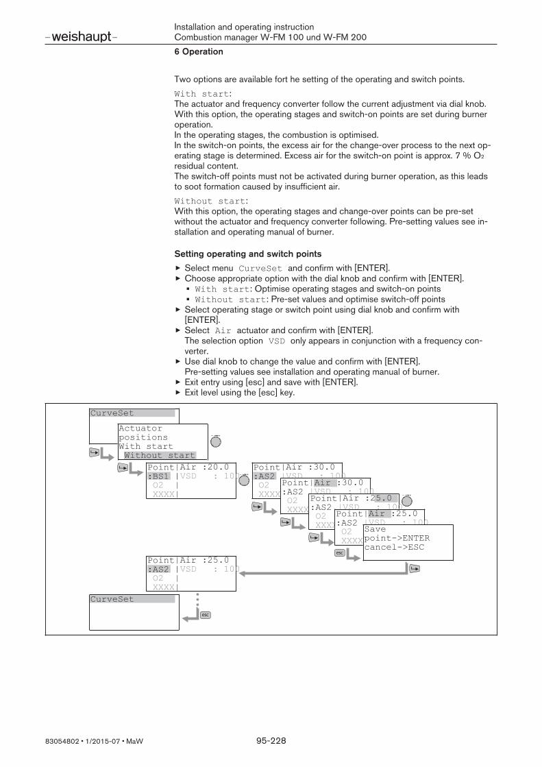
Installation and operating instructionCombustion manager W-FM 100 und W-FM 2006 Operation
83054802 1/2015-07 MaW 95-228
Two options are available fort he setting of the operating and switch points.With start:The actuator and frequency converter follow the current adjustment via dial knob.With this option, the operating stages and switch-on points are set during burneroperation.In the operating stages, the combustion is optimised.In the switch-on points, the excess air for the change-over process to the next op-erating stage is determined. Excess air for the switch-on point is approx. 7 % O2
residual content.The switch-off points must not be activated during burner operation, as this leadsto soot formation caused by insufficient air.Without start:With this option, the operating stages and change-over points can be pre-setwithout the actuator and frequency converter following. Pre-setting values see in-stallation and operating manual of burner.
Setting operating and switch pointsSelect menu CurveSet and confirm with [ENTER].Choose appropriate option with the dial knob and confirm with [ENTER].With start: Optimise operating stages and switch-on pointsWithout start: Pre-set values and optimise switch-off points
Select operating stage or switch point using dial knob and confirm with[ENTER].Select Air actuator and confirm with [ENTER]. The selection option VSD only appears in conjunction with a frequency con-verter.Use dial knob to change the value and confirm with [ENTER].Pre-setting values see installation and operating manual of burner.Exit entry using [esc] and save with [ENTER].Exit level using the [esc] key.
CurveSet
ActuatorpositionsWith start Without start
Point:AS2
|Air :30.0
O2 XXXX
|VSD : 100Point:AS2
|Air :30.0
O2 XXXX
|VSD : 100Point:AS2
|Air :25.0
O2 XXXX
|VSD : 100Point:AS2
|Air :25.0
O2 XXXX
|VSD : 100Savepoint>ENTERcancel>ESC
CurveSet
Point:BS1 |VSD : 100
|Air :20.0|||
O2 XXXX
Point:AS2 |VSD : 100
|Air :25.0|||
O2 XXXX

Installation and operating instructionCombustion manager W-FM 100 und W-FM 2006 Operation
83054802 1/2015-07 MaW 96-228
6.9.7 Load range
LoadLimits
Param & Display RatioControl GasSettingsOilSettings
LoadLimits MinLoad_… MaxLoad_…
In modulating operation, the load limits restrict the load range within the compoundcurves programmed. On dual fuel burners, the load limits for each fuel can be setseparately.Minimum load:Parameter MinLoad_… limits the load range downward (partial load). Minimumload can not be set below load point 1, in conjunction with O2 trim not below loadpoint 2.Maximum load:Parameter MaxLoad_… limits the load range upwards (full load).
0 % 100 %
P1
1
3
2
1 Minimum load MinLoad_…2 Maximum load MaxLoad_…3 Load range

Installation and operating instructionCombustion manager W-FM 100 und W-FM 2006 Operation
83054802 1/2015-07 MaW 97-228
Fade-out partial range
Param & Display RatioControl GasSettingsOilSettings
Load mask outLoadMaskLowLimitLoadMaskHighLim
Parameter Load Mask out can be used to fade out part of the load range,which could lead to operating problems due to site conditions. On dual fuel burn-ers, the partial range for each fuel can be set separately. The faded-out partialrange can be driven through but not started directly. The burner drives from thebottom to the lower limit and passes through the partial range only when the loadsetpoint reached the upper limit. From the upper range, the burner remains at theupper limit and drives through the partial range only when the load setpoint hasreached the lower limit.Lower limit partial range:Parameter LoadMaskLowLimit determines the lower limit. The lower limit cannot be set above the upper limit.Upper limit partial range:Parameter LoadMaskHighLim determines the upper limit. The upper limit cannot be set below the lower limit.
0 % 100 %
P1
1
3
2
1 Lower limit partial range LoadMaskLowLimit2 Upper limit partial range LoadMaskHighLim3 Faded-out partial range
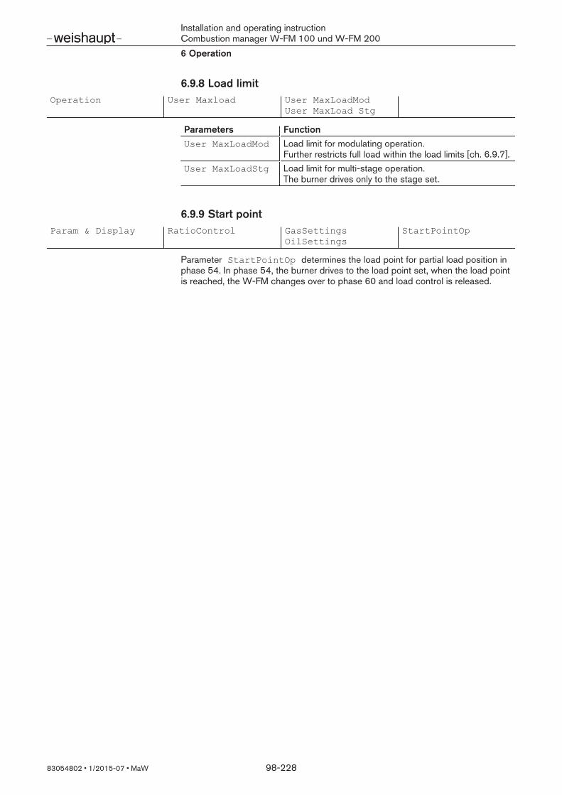
Installation and operating instructionCombustion manager W-FM 100 und W-FM 2006 Operation
83054802 1/2015-07 MaW 98-228
6.9.8 Load limitOperation User Maxload User MaxLoadMod
User MaxLoad Stg
Parameters FunctionUser MaxLoadMod Load limit for modulating operation.
Further restricts full load within the load limits [ch. 6.9.7].User MaxLoadStg Load limit for multi-stage operation.
The burner drives only to the stage set.
6.9.9 Start pointParam & Display RatioControl GasSettings
OilSettingsStartPointOp
Parameter StartPointOp determines the load point for partial load position inphase 54. In phase 54, the burner drives to the load point set, when the load pointis reached, the W-FM changes over to phase 60 and load control is released.

Installation and operating instructionCombustion manager W-FM 100 und W-FM 2006 Operation
83054802 1/2015-07 MaW 99-228
6.10 O2 controllerO2 trim is only possible in modulating operation with W-FM 200 with O2 module.O2 trim is fuel specific and must be set separately for each fuel on dual fuel burn-ers.O2 trim and O2 monitor in conjunction with the O2 residual content are at the com-bustion limit and the resulting O2 compound curve. An idealised minimum O2 value is advantages for the control behaviour. When op-timising the minimum O2 value increase rather than decrease. In conjunction withCO control (accessory) the minimum O2 value must be set to ap-prox. 0.25 to 0.5 percentage points below the combustion limit.
0
0,5
1,0
1,5
2,0
2,5
3,0
3,5
4,0
4,5
5,0
5,5
6,0
6,5
0 10 20 30 40 50 60 70 80 90 100
2
1
3
4
5
6
1 Burner capacity [%]2 O2 content in the flue gas [%]3 O2 residual content at the combustion limit4 Minimum O2 value for O2 monitor5 O2 setpoint for O2 trim6 O2 compound, excess air in the load points 20 to 25 %
With frequency converterOn burners with frequency converter, parameter VSD can be used to determine ifthe frequency converter is to be included in O2 trim [ch. 6.9.3].
Pre-controlThe O2 controller is equipped with a pre-control function. The pre-control calcu-lates the air ratings reduction for the entire load range relative to the fuel on thebasis of measured values during commissioning. If the load is changed, the air influ-encing actuators drive to the calculated position, whilst the fuel actuator drives toits load position. O2 trim is only activated if temperature or air pressure deviationsoccur and and then drives the air influencing actuators.To ensure the pre-control operates correctly, the load apportionment must matchthe fuel throughput in each load point [ch. 6.9.5].

Installation and operating instructionCombustion manager W-FM 100 und W-FM 2006 Operation
83054802 1/2015-07 MaW 100-228
6.10.1 O2 controller operating modeParam & Display O2Ctrl/Limit GasSettings
OilSettingsOptgMode
orParam & Display SystemConfig O2Ctrl/LimitGas
O2Ctrl/LimitOil
Using operating mode:the O2 controller and O2-monitor can be activated or deactivated,the behaviour when a fault occurs can be defined.
The operating mode can be set separately for each fuel.
Deactivating manually (man deact)
Parameter man deact deactivates the O2 controller and O2 monitor and theburner operates to the compound curves. This parameter is only used to create thecompound curve during commissioning, it is not suitable for normal operation.
O2 monitor only (O2 Alarm)
Parameter O2 Alarm only activates the O2 monitor.If the O2 sensor has not reached the operating temperature at burner start, a startprevention is initiated. If the O2 monitor is triggered or if an O2 fault occurs, theW-FM initiates a controlled shutdown with single repetition, then lockout occurs.
O2 controller and O2 monitor (O2Control)
Parameter O2Control activates the O2 controller and O2 monitor.If the O2 sensor has not reached the operating temperature at burner start, a startprevention is initiated. If the O2 monitor is triggered or if an O2 fault occurs, theW-FM initiates a controlled shutdown with single repetition, then lockout occurs.
Automatically deactivate control (conAutoDeac)
Parameter conAutoDeac activates the O2 controller and O2 monitor.The burner starts before the O2 sensor has reached operating temperature. O2 trimonly starts once the operating temperature has been reached and the sensor testhas been successfully carried out.If the maximum O2 monitor is triggered or if an O2 fault occurs, the W-FM changesover to operating mode auto deact.If the minimum O2 monitor is triggered the W-FM drives back to the compoundcurves. After a time of 3 times Tau the O2 content is tested again. The time con-stant Tau is determined automatically during standardisation [ch. 6.10.4].
When the O2 content exceeds the minimum limit the W-FM releases O2 trim.If the O2 content drops below the minimum limit, the W-FM initiates a safetyshutdown with repetition. The number of repetitions can be set in parameterNumMinUntilDeact , see [ch. 6.10.2]. If the number of repetitions is ex-ceeded, the W-FM changes over to operating mode auto deact.
Installation and operating instructionCombustion manager W-FM 100 und W-FM 2006 Operation
83054802 1/2015-07 MaW 101-228
Automatic deactivation (auto deact)
Do not select this operating mode.Parameter auto deact is automatically activated when a fault occurs in operat-ing mode conAutoDeac . The O2 controller is deactivated and the burner oper-ates to the compound curves. A fault message appears in the display. If the operat-ing mode is changed over the fault message disappears [ch. 6.10.23]. The O2 controller can also be deactivated via a signal at input X5-03:2 [ch. 6.8.9].

Installation and operating instructionCombustion manager W-FM 100 und W-FM 2006 Operation
83054802 1/2015-07 MaW 102-228
6.10.2 O2 monitorParam & Display O2Ctrl/Limit GasSettings
OilSettingsO2 Alarm O2 Alarm
O2 MaxValueNumMinUntilDeact
The W-FM monitors the O2 content in the flue gas using a sensor on the O2 mod-ule. The limit values for the O2 alarm are defined using parameters O2 MinValueand O2 MaxValue .
O2 minimum monitorIn parameter O2 Alarm , the setting under O2 MinValue stipulates the lowerlimit for the O2 monitor.If the O2 content in the flue gas drops below this lower limit for more than3 seconds, the W-FM reacts in accordance with the operating mode set[ch. 6.10.1].An O2 MinValue has to be defined as the lower limit in each load point. TheO2 MinValue results from the O2 content in the flue gas at the combustion limit.The O2 MinValue can be entered direct at each load point or can be determ-ined by reducing the air rating:
Select menu O2 Alarm and confirm with [ENTER].Select load point using dial knob and confirm with [ENTER] key.Select entry type 1 or 2.
Operating modeO2 trimO2 monitorControl parametersO2 monitor
O2 MaxValueNumMinUntilDeactPoint: 1 13.9%
O2 MinValue :XXXXPAir manual:
Point: 9 100%O2 MinValue :XXXXPAir manual:Point: 9 100%
O2 MinValue :XXXXPAir manual:
Point: 9 100%O2 MinValue :XXXXPAir manual:
1
2
1 Direct entry (O2 MinValue)If the O2 min value for the load point is known, the value can be assigned dir-ectly.
2 Determine O2 min value (PAir Manual)The air rating is reduced manually in the load point, the O2 content is determ-ined and saved as O2 MinValue.

Installation and operating instructionCombustion manager W-FM 100 und W-FM 2006 Operation
83054802 1/2015-07 MaW 103-228
Direct entry:Select O2 MinValue and confirm with [ENTER].Change values using the dial knob and confirm with [ENTER].Exit entry using [esc].
Point: 9 100%O2 MinValue : 0.7PAir manual:
Point: 9 100%O2 MinValue :XXXXPAir manual:Point: 9 100%
O2 MinValue :XXXXPAir manual: 0.0
Point: 9 100%O2 MinValue : 0.7PAir manual: 0.0Point: 9 100%
O2 MinValue : 0.7PAir manual: 0.0
Determine O2 min value:Select parameter PAir Manual and confirm with [ENTER].The display shows the current O2 actual value and the burner drives to the loadpoint.Reduce air rating using the dial knob until the combustion limit is reached(CO content approx. 100 ppm or smoke number approx. 1).Press [ENTER] to accept the O2 actual value.The display shows the value determined as O2 MinValue.Exit entry using [esc].
Point: 9 100%O2 MinValue : 0.7PAir manual:
Point: 9 100%O2 MinValue :XXXXPAir manual:
Point: 9 100%O2 MinValue : 3.8PAir manual: 0.0
Point: 9 100%O2 MinValue : 0.7PAir manual:10.4
Point: 9 100%O2 MinValue : 0.7PAir manual:10.4
O2-maximum monitorParameter O2 MaxValue determines the upper limit value for the O2 monitor.The limit value is valid across the entire load range. If the O2 content in the flue gasexceeds this limit value for more than 3 seconds, the W-FM reacts in accordancewith the operating mode set [ch. 6.10.1].
Repetition for O2 minimum monitorParameter NumMinUntilDeact determines the number of repetitions until theO2 controller is deactivated. The parameter is only relevant, if the operating mode isset to conAutoDeac, see [ch. 6.10.1].If a rapid load change triggers the O2 minimum monitor, increase parameterO2ModOffset, see [ch. 6.10.4].

Installation and operating instructionCombustion manager W-FM 100 und W-FM 2006 Operation
83054802 1/2015-07 MaW 104-228
6.10.3 O2 trimParam & Display O2Ctrl/Limit GasSettings
OilSettingsO2 Control
The W-FM monitors the O2 content in the flue gas using a sensor on the O2 mod-ule.
Moisture in the O2 sensor.With new sensors or if the sensor has been switched off for extended periods,moisture may form in the sensor and distort the measured value. A longer heat-upprocess through the internal sensor heating displaces this moisture.
Heat up the sensor prior to adjusting the O2 trim.
Parameter LowFireAdaptPtNo can be used to set from which load point O2
trim is possible [ch. 6.10.4]. During commissioning, in parameter O2 Control standardisation is carried outat each point from the load point determined up to full load and the O2 setpoint isdetermined. During standardisation the air influencing actuators drive open on thecompound curve according to the standardised value and reduce the air quantity,the fuel quantity remains unchanged. No standardisation is carried out in load point 1, the reference line between loadpoint 1 and load point 2 only serves to reduce air. To ensure O2 trim is possibleacross the entire load range, point 1 must be approx. 50 % below partial load(point 2).In the load point set under LowFireAdaptPtNo and the last load point (full load)the W-FM carries out an adaption. In these two points, the W-FM drives back tothe compound curve after saving. The delay time before the O2 content at thesensor changes is saved as time constant Tau.
The setpoint for O2 trim should be approx. 0.5 … 1 %point above the O2MinValue of the O2 monitor. The O2 value in the load points of the compound curve should be approx.2 % points above the setpoint for O2 trim.
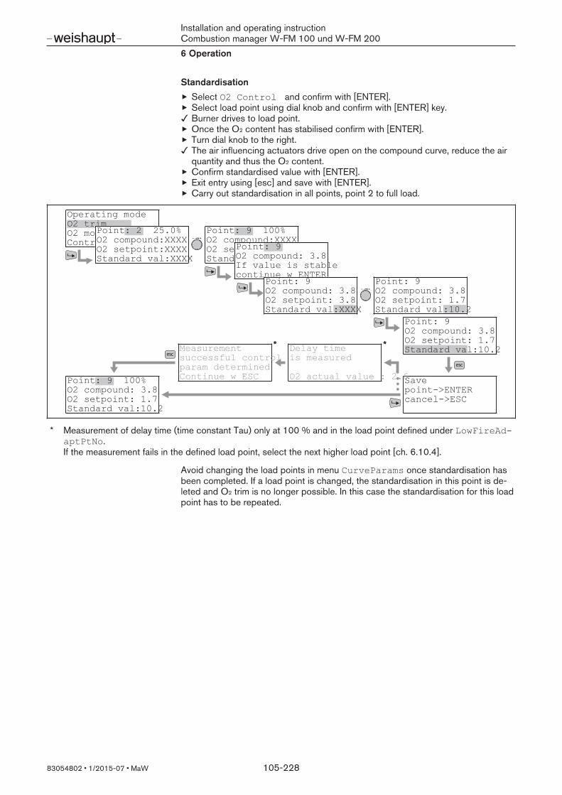
Installation and operating instructionCombustion manager W-FM 100 und W-FM 2006 Operation
83054802 1/2015-07 MaW 105-228
StandardisationSelect O2 Control and confirm with [ENTER].Select load point using dial knob and confirm with [ENTER] key.Burner drives to load point.Once the O2 content has stabilised confirm with [ENTER].Turn dial knob to the right.The air influencing actuators drive open on the compound curve, reduce the airquantity and thus the O2 content.Confirm standardised value with [ENTER].Exit entry using [esc] and save with [ENTER].Carry out standardisation in all points, point 2 to full load.
Operating modeO2 trimO2 monitorControl parameters
Point: 2 25.0%O2 compound:XXXXO2 setpoint:XXXXStandard val:XXXX
Point: 9 100%O2 compound:XXXXO2 setpoint:XXXXStandard val:XXXX
Point: 9O2 compound: 3.8If value is stablecontinue w ENTER
Point: 9 O2 compound: 3.8O2 setpoint: 3.8Standard val:XXXX
Point: 9 O2 compound: 3.8O2 setpoint: 1.7Standard val:10.2
Point: 9 O2 compound: 3.8O2 setpoint: 1.7Standard val:10.2
Savepoint>ENTERcancel>ESC
Delay timeis measured
O2 actual value : 2.6Point: 9 100%O2 compound: 3.8O2 setpoint: 1.7Standard val:10.2
Measurement successful controlparam determinedContinue w ESC
* *
* Measurement of delay time (time constant Tau) only at 100 % and in the load point defined under LowFireAdaptPtNo. If the measurement fails in the defined load point, select the next higher load point [ch. 6.10.4].
Avoid changing the load points in menu CurveParams once standardisation hasbeen completed. If a load point is changed, the standardisation in this point is de-leted and O2 trim is no longer possible. In this case the standardisation for this loadpoint has to be repeated.

Installation and operating instructionCombustion manager W-FM 100 und W-FM 2006 Operation
83054802 1/2015-07 MaW 106-228
6.10.4 O2 control parametersParam & Display O2Ctrl/Limit GasSettings
OilSettingsControlParam
The control parameters are fuel specific and must be set separately for each fuel ondual fuel burners.
PI parameters and time constant TauThis parameter influences the reaction behaviour of O2 trim.
Parameters FunctionP LowFireP HighFire
Proportional part of O2 trim.The greater the value set, the faster the regulation willcommence. If the value set is too great the controllertends to over-oscillate.
I LowFireI HighFire
Integral part of O2 trim.The smaller the value set, the faster the regulation willcommence. If the value is set too small, the controllertends to oscillate.
Tau LowFire The flue gas reaction time measured during standardisa-tion in the point set under LowFireAdaptPtNo .
Tau HighFire The flue gas reaction time measured during standardisa-tion at 100 % burner capacity.
Partial load adaption point (LowFireAdaptPtNo)
Parameter LowFireAdaptPtNo determines the load point at which Tau Low-Fire (flue gas reaction time) is measured. If the flue gas velocity in the current partialload adaption point is too low, the measurement fails and the next higher point hasto be selected. O2 trim is not possible below the partial load adaption point set.
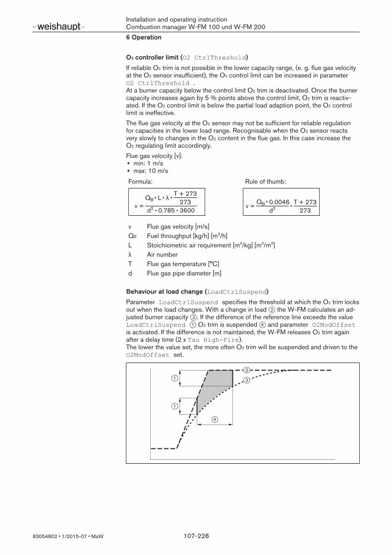
Installation and operating instructionCombustion manager W-FM 100 und W-FM 2006 Operation
83054802 1/2015-07 MaW 107-228
O2 controller limit (O2 CtrlThreshold)
If reliable O2 trim is not possible in the lower capacity range, (e. g. flue gas velocityat the O2 sensor insufficient), the O2 control limit can be increased in parameterO2 CtrlThreshold . At a burner capacity below the control limit O2 trim is deactivated. Once the burnercapacity increases again by 5 % points above the control limit, O2 trim is reactiv-ated. If the O2 control limit is below the partial load adaption point, the O2 controllimit is ineffective.The flue gas velocity at the O2 sensor may not be sufficient for reliable regulationfor capacities in the lower load range. Recognisable when the O2 sensor reactsvery slowly to changes in the O2 content in the flue gas. In this case increase theO2 regulating limit accordingly.Flue gas velocity [v]:
min: 1 m/smax: 10 m/s
Formula: Rule of thumb:
v =QB L λ
T + 273273
d2 0.785 3600v = QB 0.0046
d2T + 273
273
v Flue gas velocity [m/s]QB Fuel throughput [kg/h] [m3/h]L Stoichiometric air requirement [m3/kg] [m3/m3]λ Air numberT Flue gas temperature [°C]d Flue gas pipe diameter [m]
Behaviour at load change (LoadCtrlSuspend)
Parameter LoadCtrlSuspend specifies the threshold at which the O2 trim locksout when the load changes. With a change in load 2 the W-FM calculates an ad-justed burner capacity 3. If the difference of the reference line exceeds the valueLoadCtrlSuspend 1 O2 trim is suspended 4 and parameter O2ModOffsetis activated. If the difference is not maintained, the W-FM releases O2 trim againafter a delay time (2 x Tau HighFire).The lower the value set, the more often O2 trim will be suspended and driven to theO2ModOffset set.
2
1
1 3
4
Installation and operating instructionCombustion manager W-FM 100 und W-FM 2006 Operation
83054802 1/2015-07 MaW 108-228
O2-Offset (O2ModOffset)
Increase of the O2 content in percentage points, if O2 trim is suspended via para-meter LoadCtrlSuspend when the load is changed. O2ModOffset en-sures that the O2 min value is maintained in case of LoadCtrlSuspend.If the threshold value LoadCtrlSuspend is exceeded when the load ischanged, the air influencing actuators operate and increase the O2 content by thevalue set, then the fuel actuator operates.In conjunction with CO trim the W-FM increases the O2 setpoint by O2 offset if theCO limit value has been exceeded.
Pre-control (Type Air Change)
Parameter Type Air Change influences the calculation procedure of the pre-control[ch. 6.10].
Parameters Functionlike theory Recommended for fuel gas.
Temperature and air pressure fluctuations influence thefuel throughput.
like P air Recommended for fuel oil. Temperature and air pressure fluctuations do not influ-ence the fuel throughput.
LambdaFact1 Not recommended. Only for burners with stoichiometric fuel/air ratio(Lambda factor 1).
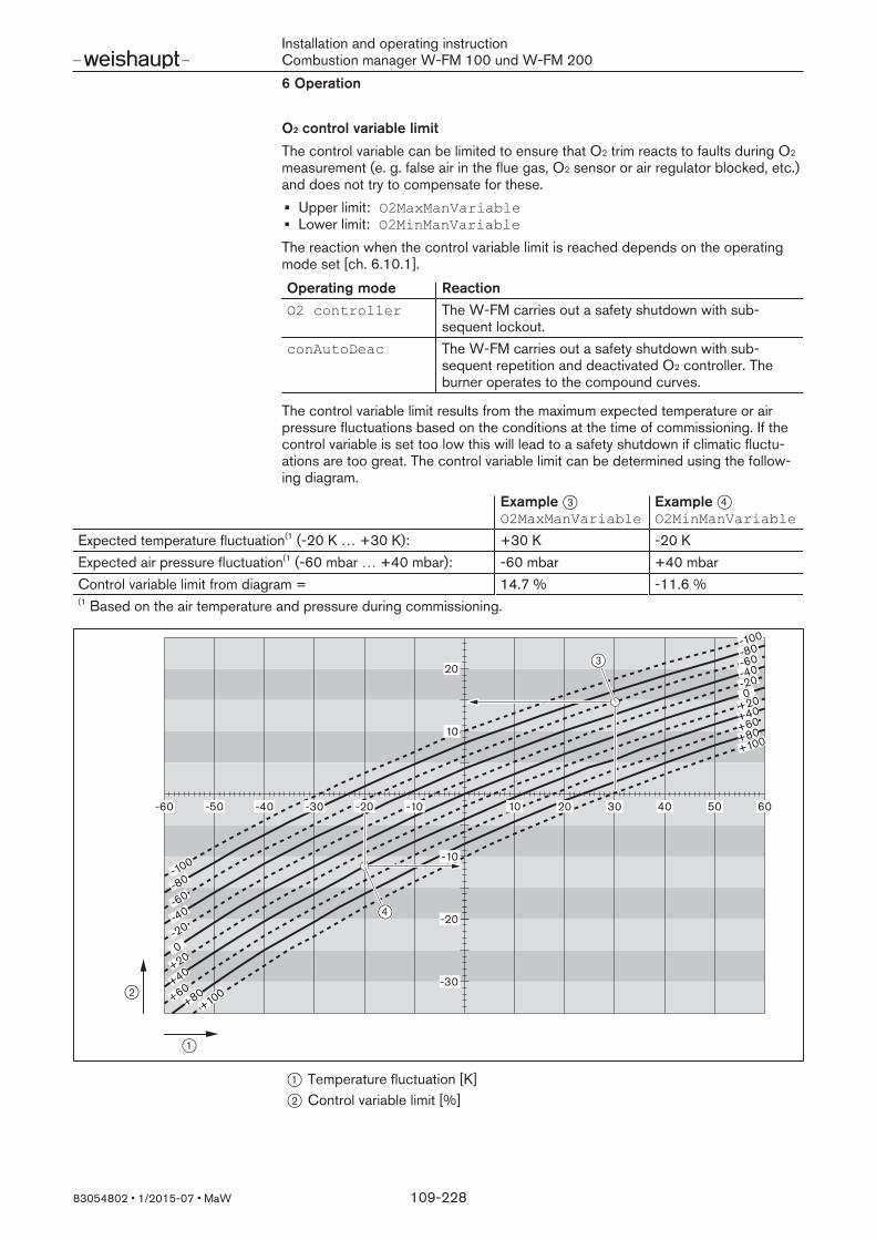
Installation and operating instructionCombustion manager W-FM 100 und W-FM 2006 Operation
83054802 1/2015-07 MaW 109-228
O2 control variable limitThe control variable can be limited to ensure that O2 trim reacts to faults during O2
measurement (e. g. false air in the flue gas, O2 sensor or air regulator blocked, etc.)and does not try to compensate for these.
Upper limit: O2MaxManVariableLower limit: O2MinManVariable
The reaction when the control variable limit is reached depends on the operatingmode set [ch. 6.10.1].
Operating mode ReactionO2 controller The W-FM carries out a safety shutdown with sub-
sequent lockout.conAutoDeac The W-FM carries out a safety shutdown with sub-
sequent repetition and deactivated O2 controller. Theburner operates to the compound curves.
The control variable limit results from the maximum expected temperature or airpressure fluctuations based on the conditions at the time of commissioning. If thecontrol variable is set too low this will lead to a safety shutdown if climatic fluctu-ations are too great. The control variable limit can be determined using the follow-ing diagram.
Example 3O2MaxManVariable
Example 4O2MinManVariable
Expected temperature fluctuation(1 (-20 K … +30 K): +30 K -20 KExpected air pressure fluctuation(1 (-60 mbar … +40 mbar): -60 mbar +40 mbarControl variable limit from diagram = 14.7 % -11.6 %€€
(1 Based on the air temperature and pressure during commissioning.
10
-10
-20
-30
20
10 20 30 40 50 60-10-20-30-40-50-60
-100
-80
-60
-40
-20
0
+100
-100
-60-40-20
-80
0
+20
+40
+60+80
+100
+20+40+60+80
4
2
1
3
1 Temperature fluctuation [K]2 Control variable limit [%]

Installation and operating instructionCombustion manager W-FM 100 und W-FM 2006 Operation
83054802 1/2015-07 MaW 110-228
6.10.5 O2 start modeParam & Display O2Ctrl/Limit GasSettings
OilSettingsStartmode
O2 offset at burner start (O2InitOffset)
Parameter O2InitOffset is not used in the Weishaupt configuration and hasno function.
Release O2 trim (NumberTauSuspend)
Parameter NumberTauSuspend determines the factor for the calculation of O2
block time. O2 block time = Tau LowFire x NumberTauSuspendDue to the reaction and settling time of the O2 sensor, the O2 regulator is initiallyblocked at burner start. The O2 block time starts in operating setting (phase 60).After the block time the W-FM initialises the O2 regulator and releases O2 trim aftera further 4 x Tau LowFire.As the two possible O2 sensors differ in reaction and settling time, NumberTauSuspend depends on the sensor used.
O2 sensor Recommended NumberTauSuspendQGO 20 approx. 10 … 20QGO 21 above 40
The block time also applies to the function CO monitor and CO controller[ch. 6.11].At burner start, the CO content is increased. Once the flame has formed and stabil-ised, the CO content drops. If the block time is too short, the increased CO con-tent at burner start will trigger a safety shutdown.
Combustion air temperature during commissioning (Adjust. Temp O2)
Parameter Adjust. Temp O2 determines the air temperature during commis-sioning in conjunction with a supply air sensor, this is not used in the Weishauptconfiguration and has no function.
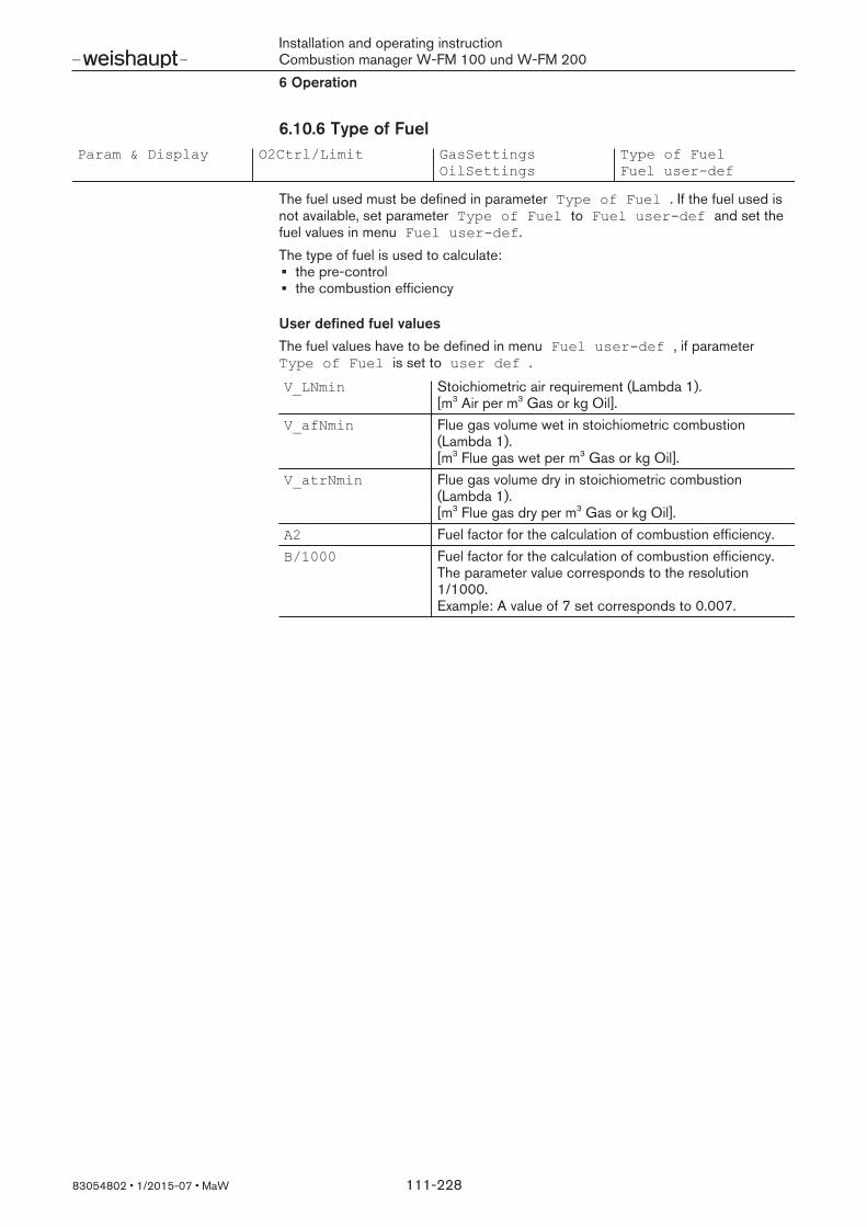
Installation and operating instructionCombustion manager W-FM 100 und W-FM 2006 Operation
83054802 1/2015-07 MaW 111-228
6.10.6 Type of FuelParam & Display O2Ctrl/Limit GasSettings
OilSettingsType of FuelFuel userdef
The fuel used must be defined in parameter Type of Fuel . If the fuel used isnot available, set parameter Type of Fuel to Fuel userdef and set thefuel values in menu Fuel userdef.The type of fuel is used to calculate:
the pre-controlthe combustion efficiency
User defined fuel valuesThe fuel values have to be defined in menu Fuel userdef , if parameterType of Fuel is set to user def .
V_LNmin Stoichiometric air requirement (Lambda 1).[m3 Air per m3 Gas or kg Oil].
V_afNmin Flue gas volume wet in stoichiometric combustion(Lambda 1).[m3 Flue gas wet per m3 Gas or kg Oil].
V_atrNmin Flue gas volume dry in stoichiometric combustion(Lambda 1).[m3 Flue gas dry per m3 Gas or kg Oil].
A2 Fuel factor for the calculation of combustion efficiency.B/1000 Fuel factor for the calculation of combustion efficiency.
The parameter value corresponds to the resolution1/1000.Example: A value of 7 set corresponds to 0.007.

Installation and operating instructionCombustion manager W-FM 100 und W-FM 2006 Operation
83054802 1/2015-07 MaW 112-228
6.10.7 O2 sensorParam & Display O2 module Configuration O2 sensor
Parameter O2 sensor activates the O2 sensor connected.
Setting Functionno sensor No O2 sensor fitted, O2 trim not possible.QGO20 QGO 20 fitted, for:
Gas burnerOil burner (fuel oil EL)Dual fuel burner (fuel oil EL)
QGO21 QGO 21 fitted, for:Heavy oil burner (fuel oil MS and S)Dual fuel burner (fuel oil MS and S)
The O2 sensor QGO 21 has an increased reaction and settling time. Due to thisbehaviour, the release of O2 trim at burner start has to be delayed for longer. Inconjunction with QGO 21, the factor has to be set to minimum 40 in parameterNumberTauSuspend , see [ch. 6.10.5].
6.10.8 Service interval for O2 sensorParam & Display O2 module Configuration O2SensServTim
O2SensServTimRes
Setting the service intervalParameter O2SensServTim stipulates the service interval in days for the the O2
sensor. The interval is deactivated if the setting is "0". The interval is compared with the total operating hours counter. If the interval haselapsed, a message appears in the ABE and O2 trim reacts according to the oper-ating mode set [ch. 6.10.1].
O2 trim is deactivated in operating mode conAutoDeac, the O2 monitor re-mains activated.Lockout occurs in operating mode O2 Alarm or O2 controller.
Reset service intervalParameter O2SensServTimRes resets the service interval.If O2 trim is set to auto deact, the operating mode has to be reset to conAutoDeac.

Installation and operating instructionCombustion manager W-FM 100 und W-FM 2006 Operation
83054802 1/2015-07 MaW 113-228
6.10.9 Define temperature sensorParam & Display O2 module Configuration SupAirTempSens
FueGasTempSens
Parameter SupAirTempSens is used to define the combustion air sensor fitted[ch. 3.3.24].Select Pt1000 in conjunction with CO control.The flue gas sensor fitted is defined in parameter FueGasTempSens, see[ch. 3.3.23].The sensors have no influence on O2 trim, they are used to calculate combustionefficiency.
6.10.10 Flue gas temperature warning thresholdParam & Display O2 module Configuration MaxTempFlGasGas
MaxTempFlGasOil
Parameter MaxTempFlueGas… determines a warning threshold for the flue gastemperature. A flue gas temperature sensor has to be fitted for this function[ch. 3.3.23].The threshold is determined separately for oil and gas. Set the threshold approx.20 % above the maximum flue gas temperature measured during commissioning[ch. 6.10.19].
CAUTION
Damage to the O2 sensor caused by overheatingFlue gas temperature above 300 °C can damage the O2 sensor.
Avoid flue gas temperatures above 300 °C at the O2 sensor.
If the flue gas exceeds the temperature set, a message appears in the ABE.The warning indicates an increased flue gas loss, the heat exchanger should becleaned.
CO functionIn conjunction with the CO function the input of the combustion air sensor is usedfor signal evaluation [ch. 6.11].For the signal evaluation an apparent intake air temperature of up to 730 ° C isgenerated. To ensure that the W-FM does not detect implausible values, the warn-ing threshold in conjunction with the CO function must be set to 850 °C in para-meter FlueGas… .

Installation and operating instructionCombustion manager W-FM 100 und W-FM 2006 Operation
83054802 1/2015-07 MaW 114-228
6.10.11 Combustion efficiencyParam & Display O2 module Process Data CombEfficiency
orOperation O2 module CombEfficiency
Combustion efficiencyParameter CombEfficiency shows the combustion efficiency.The following sensors must be fitted and configured for the combustion efficiencyto be shown:
O2 sensor [ch. 3.3.25]Combustion air sensor [ch. 3.3.24]Flue gas temperature sensor [ch. 3.3.23]
6.10.12 O2 controller control variableParam & Display O2Ctrl/Limit Process Data ManVar O2 Ctrl
Parameter ManVar O2 Ctrl shows the current control variable of the O2 con-troller.
6.10.13 Status O2 controllerParam & Display O2Ctrl/Limit Process Data Status O2 Ctrl
Parameter Status O2 Ctrl shows the current status of the O2 controller.
deactivated The O2 controller is deactivated. The burner operates tothe compound curves.
locked The O2 controller is blocked (sensor testing, partial loadnot achieved, …).
LockTStart Blocked time in partial load elapses (Tau LowFire xNumberTauSuspend).
InitContr Initialisation time elapses (4 x Tau LowFire).LockTLoad The O2 controller is blocked due to a load adjustment.activate The O2 controller is activated and controls to the O2 set-
point.LockTCAct The O2 controller is blocked for a duration of 2 x Tau due
a control input.LockCOx The CO limit value has been exceeded, the O2 controller
is blocked.
6.10.14 Air ratingParam & Display O2Ctrl/Limit Process Data Airrelated Load
Parameter Airrelated Load shows the current air rating of the fuel air ratio.
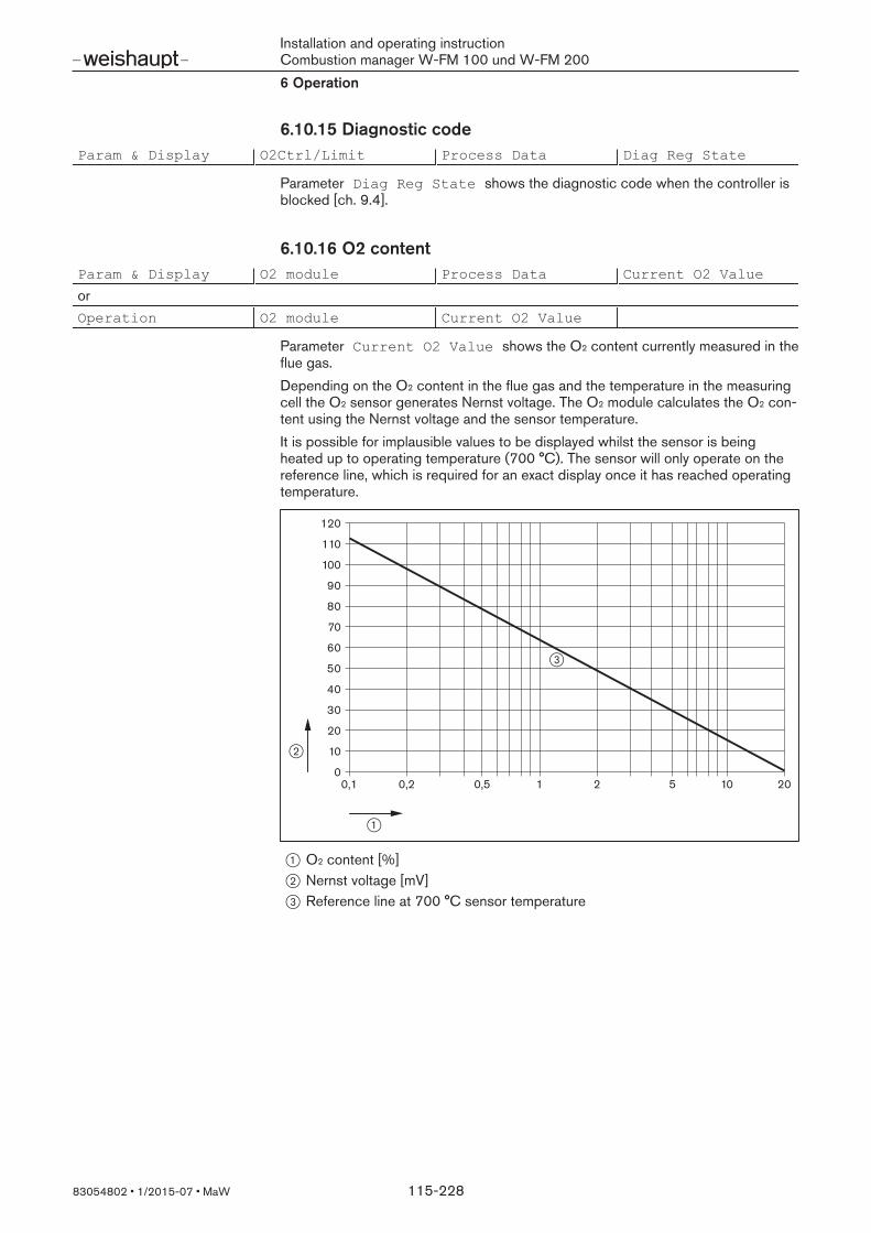
Installation and operating instructionCombustion manager W-FM 100 und W-FM 2006 Operation
83054802 1/2015-07 MaW 115-228
6.10.15 Diagnostic codeParam & Display O2Ctrl/Limit Process Data Diag Reg State
Parameter Diag Reg State shows the diagnostic code when the controller isblocked [ch. 9.4].
6.10.16 O2 contentParam & Display O2 module Process Data Current O2 Value
orOperation O2 module Current O2 Value
Parameter Current O2 Value shows the O2 content currently measured in theflue gas.Depending on the O2 content in the flue gas and the temperature in the measuringcell the O2 sensor generates Nernst voltage. The O2 module calculates the O2 con-tent using the Nernst voltage and the sensor temperature.It is possible for implausible values to be displayed whilst the sensor is beingheated up to operating temperature (700 °C). The sensor will only operate on thereference line, which is required for an exact display once it has reached operatingtemperature.
0,1 0,2 0,5 1 2 5 10 200
10
20
30
40
50
60
70
80
90
100
110
120
2
1
3
1 O2 content [%]2 Nernst voltage [mV]3 Reference line at 700 °C sensor temperature

Installation and operating instructionCombustion manager W-FM 100 und W-FM 2006 Operation
83054802 1/2015-07 MaW 116-228
6.10.17 O2 setpointParam & Display O2 module Process Data O2 Setpoint
orOperation O2 module O2 Setpoint
Parameter O2 Setpoint shows the O2 setpoint set for the current burner capa-city.The O2 setpoints are defined during commissioning.
6.10.18 Combustion air temperature / CO switching thresholdParam & Display O2 module Process Data Supply air temper
ature
orOperation O2 module Supply air temper
ature
Parameter Supply air temperature shows the combustion air temperaturecurrently measured, if the relevant sensor is connected to the O2 module.In conjunction with CO monitoring, the parameter shows the status of the COswitching threshold [ch. 3.3.24].
6.10.19 Flue gas temperatureParam & Display O2 module Process Data Flue gas temperat
ure
orOperation O2 module Flue gas temperat
ure
If a flue gas temperature sensor is connected to the O2 module, parameter Fluegas temperature shows the current flue gas temperature [ch. 3.3.23].
6.10.20 O2 sensor temperatureParam & Display O2 module Process Data QGO SensorTemp
Parameter QGO SensorTemp shows the current temperature of the O2 sensor.The temperature is detected by a thermocouple in the sensor, 700 °C correspondsto approx. 29.1 mV.O2 trim is activated at a sensor temperature of 700 °C (±15 °C). If the operatingtemperature is not achieved, the W-FM reacts according to the operating mode set[ch. 6.10.1]. If the temperature exceeds 750 °C, deactivate the sensor and check the electricalconnection.

Installation and operating instructionCombustion manager W-FM 100 und W-FM 2006 Operation
83054802 1/2015-07 MaW 117-228
6.10.21 O2 sensor heating capacityParam & Display O2 module Process Data QGO HeatingLoad
Parameter QGO HeatingLoad shows the current heating capacity.The percentage display indicates the impulse / pause ratio based on 2 seconds.60 % corresponds to 1.2 seconds impulse ad 0.8 seconds pause.
Heat capacityStart capacity up to 100 °C: approx. 13 %Heat-up process: approx. 60 %At operating temperature: approx. 17 %
6.10.22 O2 sensor wear and tearParam & Display O2 module Process Data QGO Resistance
Parameter QGO Resistance shows the internal resistance of the O2 sensor.The internal resistance changes during the course of the operation. With an internalresistance of less than 5 Ω or greater than 150 Ω the sensor is subject to aging. Ifthe parameter shows an internal resistance of 0 Ω, the W-FM has not yet carriedout the sensor test.
Sensor testThe W-FM carries out a sensor test every 23 hours. The O2 content must be con-stant for the test, e. g. in pre-purge or at a static load. If a constant O2 content isnot achieved within 24 hours, the W-FM freezes the load and carries out the test. Ifthe burner is in standby, the W-FM carries out the test at the next burner start.
6.10.23 Activate / deactivate O2 controllerOperation O2Ctrl activate deactivated
activated
Parameter O2Ctrl activate activates or deactivates the O2 controller manu-ally.

Installation and operating instructionCombustion manager W-FM 100 und W-FM 2006 Operation
83054802 1/2015-07 MaW 118-228
6.11 CO monitor and CO controllerComponents required for CO function:
Combustion manager W-MF 200 in version with FGR and CO (LMV52.4…)O2 moduleO2 sensor QGO 20, for fuels Gas and fuel oil ELCO measurement amplifier LT3Combi sensor KS1-D for CO measurementResistance board for connection CO measurement amplifier to O2 module
Additional informationRefer to the manual of the measuring amplifier LT 3 and combination sensor KS1-Dprior to commissioning. The manual is available to download from the -w- Portal.
The function CO monitor and CO controller must only be activated in conjunctionwith O2 trim.Depending on the combustion system it is possible that soot particles at the COsensor can produce a false CO signal when using fuel oil EL. In this case, only usethe function CO monitor or deactivate the CO function in the operating mode foroil. On dual fuel burners, there is no limitation for gas.A CO sensor and a measurement amplifier with digital output for signal evaluationis required for CO detection. The digital output 3 (Out3) of the measurement ampli-fier is connected via a resistance board at the input of the combustion air sensor inthe O2 module [ch. 3.3.24].Digital output 3 (Out3) is evaluated via the resistance board. In this case, the ABEshows the switching status of the measurement amplifier via the combustion airtemperature.
Display Descriptionapprox. 730°C
CO limit value exceeded.Digital output 3 (Out3) open, resistance at input approx. 3.6 kΩ.
approx. 370°C
CO limit value not maintained.Digital output 3 (Out3) closed, resistance at input approx.2.4 kΩ.
The following settings have to be made in the configuration of the O2 module forsignal evaluation:
Set parameter MaxTempFlGas… to 850 °C [ch. 6.10.10]In parameter SupAirTempSens select sensor Pt1000, see [ch. 6.10.9].
A combustion air sensor is required for the calculation and display of the combus-tion efficiency. In conjunction with the CO function, the actual combustion airsensor is connected to input X60:3/4. Parameter AirTempX60PT1000 (OEMlevel) must be set to activated.CO control is an extension of the O2 controller. The difference to the normal O2 trimis that the O2 MinValue is set to approx. 0.25 … 0.5 percentage points belowthe combustion limit. If CO control is only used for one fuel on dual fuel burners,only the O2 MinValue for this fuel must be set below the combustion limit.

Installation and operating instructionCombustion manager W-FM 100 und W-FM 2006 Operation
83054802 1/2015-07 MaW 119-228
0
0,5
1,0
1,5
2,0
2,5
3,0
3,5
4,0
4,5
0 10 20 30 40 50 60 70 80 90 100
2
1
3
4
5 6
1 Burner capacity [%]2 O2 content in the flue gas [%]3 O2 residual content at the combustion limit4 Minimum O2 value for O2 monitor5 O2 setpoint for O2 trim6 O2 setpoint for O2 trim + Offset (O2ModOffset)
The digital output 3 (Out3) in the measurement amplifier is is interrogated onceafter pre-purge. If the digital output is open, the W-FM carries out a safety shut-down with repetition.Following the release of O2 trim the digital output is permanently interrogated[ch. 6.10.5]. If the CO content exceeds the limit value, the digital output in the measurementamplifier opens and the value of the resistance board changes to approx. 3.6 kΩ.The W-FM recognises that the limit has been exceeded and increases the O2 set-point by the O2ModOffset set [ch. 6.10.4].O2 trim is suspended. The air influencing actuators drive open, the O2 content in-creases and reduces the CO content in the flue gas.If the CO content drops below the limit value before the time delay of the CO mon-itor Time COx monitor has elapsed, the digital output closes and O2 trim isreactivated.If the time delay is exceeded, the W-FM carries out a safety shutdown withrepetition [ch. 6.11.2].

Installation and operating instructionCombustion manager W-FM 100 und W-FM 2006 Operation
83054802 1/2015-07 MaW 120-228
6.11.1 Operating mode CO functionParam & Display O2Ctrl/Limit COx OptgMode COx Gas
OptgMode COx Oil
On dual fuel burners, the CO monitor and CO controller can be activated or deac-tivated for each fuel separately.
Setting Functiondeactivated CO controller and CO monitor are deactivate.COx Alarm Only the CO monitor is activated.COx control CO controller and CO monitor are activated.
6.11.2 Time delay limit value exceededParam & Display O2Ctrl/Limit COx Time COx Alarm
Parameter Time COx Alarm determines the time delay until a safety shutdownwith repetition is carried out if the CO limit value is exceeded. If the number of re-petitions is exceeded, the W-FM initiates a lockout. The number of repetitions de-pend on the repetition counter of the O2 monitor (NumMinUntilDeact). see[ch. 6.10.2].If the CO content exceeds the limit value, the time delay must be long enough to al-low the burner to drive to higher excess air.

Installation and operating instructionCombustion manager W-FM 100 und W-FM 2006 Operation
83054802 1/2015-07 MaW 121-228
6.12 Load controllerThe W-FM 200 is equipped with an internal PID load controller as standard, withthe W-FM 100 the internal load controller is optional.
6.12.1 SetpointOperation BoilerSetpoint SetpointW1
SetpointW2
orParam & Display LoadController ControlParam SetpointW1
SetpointW2
Two setpoints (W1/W2) can be specified for the internal load controller usingparameters Setpoint … .The setpoints can not be set via the temperature monitor TL_Thresh_Off , see[ch. 6.12.13]. A potential free contact at input X62 can be used to switch between the setpointsW1 and W2 or to switch from an external to the internal setpoint W1 [ch. 3.3.19].

Installation and operating instructionCombustion manager W-FM 100 und W-FM 2006 Operation
83054802 1/2015-07 MaW 122-228
6.12.2 Load controller operating modeParam & Display LoadController Configuration LC_OptgMode
orParam & Display SystemConfig LC_OptgMode
The parameters in menu LC_OptgMode stipulates, wether the internal or an ex-ternal load controller is used and which source specifies the setpoint.
External load controller
Setting FunctionExtLC X503 External load controller at input X5-03 [ch. 3.3.16].ExtLC X62 External load controller with analogue load signal at input X62 [ch. 3.3.17]. In-
put X62 must be matched to the analogue signal in parameter Ext Inp X62U/I , see [ch. 6.12.4].The internal load controller converts the analogue signal into a digital load signal.This operating mode is not possible without the internal load controller.
ExtLC Bus External load controller via Bus connection [ch. 3.3.18].

Installation and operating instructionCombustion manager W-FM 100 und W-FM 2006 Operation
83054802 1/2015-07 MaW 123-228
Internal load controller
Setting FunctionIntLC Internal Load controller with setpoint input (W1/W2) via ABE.
A contact at terminals X62:1/2 can be used to switch between setpoint W1 andW2 [ch. 3.3.19].
IntLC Bus Internal load controller with setpoint input via Bus from the building managementsystem.Parameters Ext Min/MaxSetpointcan be used to limit the setpoint range[ch. 6.12.6]. A contact at terminals X62:1/2 can be used to switch to the internal setpoint W1[ch. 3.3.19].
IntLC X62 Internal load controller with analogue setpoint from the building management sys-tem at input X62 [ch. 3.3.17]. Input X62 must be matched to the analogue signalin parameter Ext Inp X62 U/I , see [ch. 6.12.4]The setpoint range results from the selected measuring range for the temperaturesensor in parameter Meas. range PtNi [ch. 6.12.5]. Parameters Ext Min/MaxSetpoint can be used to limit the setpoint range[ch. 6.12.6]. A contact at terminals X62:1/2 can be used to switch to the internal setpoint W1[ch. 3.3.19].
Changing over operating mode to internal load controller
2345
X62
0-10V
4-20mA
0
FE
10/2...10 V
0/4...20 mA
A switch contact at terminal X62:1/2 can be used to switch over from an externalload controller to the internal load controller IntLC . If the contact is closed, theinternal load contactor is activated and controls on the internal Setpoint W1.For the operating mode change-over to function, LC_OptgMode has to be set toIntLC and the internal load controller has to be adjusted. Then LC_OptgModehas to be set to the external operating mode (ExtLC ...) required.
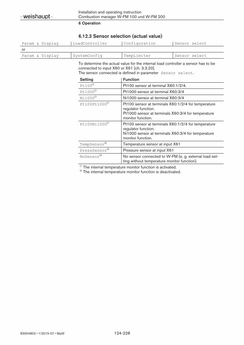
Installation and operating instructionCombustion manager W-FM 100 und W-FM 2006 Operation
83054802 1/2015-07 MaW 124-228
6.12.3 Sensor selection (actual value)Param & Display LoadController Configuration Sensor select
orParam & Display SystemConfig TempLimiter Sensor select
To determine the actual value for the internal load controller a sensor has to beconnected to input X60 or X61 [ch. 3.3.20]. The sensor connected is defined in parameter Sensor select.
Setting FunctionPt100(1 Pt100 sensor at terminal X60:1/2/4.Pt1000(1 Pt1000 sensor at terminal X60:3/4Ni1000(1 Ni1000 sensor at terminal X60:3/4Pt100Pt1000(1 Pt100 sensor at terminals X60:1/2/4 for temperature
regulator function. Pt1000 sensor at terminals X60:3/4 for temperaturemonitor function.
Pt100Ni1000(1 Pt100 sensor at terminals X60:1/2/4 for temperatureregulator function. Ni1000 sensor at terminals X60:3/4 for temperaturemonitor function.
TempSensor(2 Temperature sensor at input X61PressSensor(2 Pressure sensor at input X61NoSensor(2 No sensor connected to W-FM (e. g. external load set-
ting without temperature monitor function).€€
(1 The internal temperature monitor function is activated.(2 The internal temperature monitor function is deactivated.
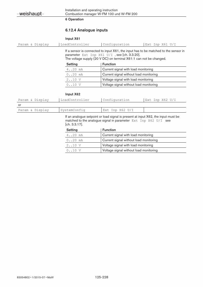
Installation and operating instructionCombustion manager W-FM 100 und W-FM 2006 Operation
83054802 1/2015-07 MaW 125-228
6.12.4 Analogue inputs
Input X61
Param & Display LoadController Configuration Ext Inp X61 U/I
If a sensor is connected to input X61, the input has to be matched to the sensor inparameter Ext Inp X61 U/I , see [ch. 3.3.20]. The voltage supply (20 V DC) on terminal X61:1 can not be changed.
Setting Function4..20 mA Current signal with load monitoring0..20 mA Current signal without load monitoring2..10 V Voltage signal with load monitoring0..10 V Voltage signal without load monitoring
Input X62
Param & Display LoadController Configuration Ext Inp X62 U/I
orParam & Display SystemConfig Ext Inp X62 U/I
If an analogue setpoint or load signal is present at input X62, the input must bematched to the analogue signal in parameter Ext Inp X62 U/I see[ch. 3.3.17].
Setting Function4..20 mA Current signal with load monitoring0..20 mA Current signal without load monitoring2..10 V Voltage signal with load monitoring0..10 V Voltage signal without load monitoring
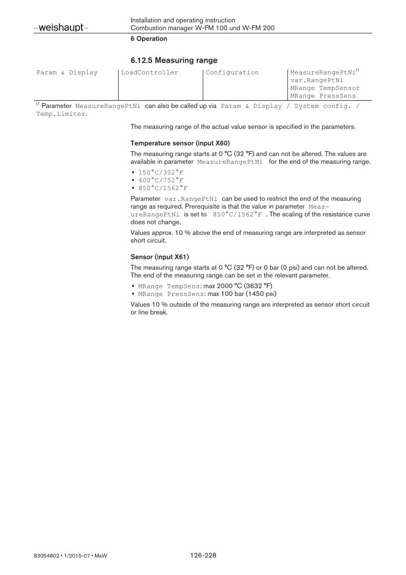
Installation and operating instructionCombustion manager W-FM 100 und W-FM 2006 Operation
83054802 1/2015-07 MaW 126-228
6.12.5 Measuring rangeParam & Display LoadController Configuration MeasureRangePtNi(1
var.RangePtNiMRange TempSensorMRange PressSens
€€
(1 Parameter MeasureRangePtNi can also be called up via Param & Display / System config. /Temp.Limiter.
The measuring range of the actual value sensor is specified in the parameters.
Temperature sensor (input X60)The measuring range starts at 0 °C (32 °F) and can not be altered. The values areavailable in parameter MeasureRangePtNi for the end of the measuring range.150°C/302°F400°C/752°F850°C/1562°F
Parameter var.RangePtNi can be used to restrict the end of the measuringrange as required. Prerequisite is that the value in parameter MeasureRangePtNi is set to 850°C/1562°F . The scaling of the resistance curvedoes not change.Values approx. 10 % above the end of measuring range are interpreted as sensorshort circuit.
Sensor (input X61)The measuring range starts at 0 °C (32 °F) or 0 bar (0 psi) and can not be altered.The end of the measuring range can be set in the relevant parameter.MRange TempSens: max 2000 °C (3632 °F)MRange PressSens: max 100 bar (1450 psi)
Values 10 % outside of the measuring range are interpreted as sensor short circuitor line break.

Installation and operating instructionCombustion manager W-FM 100 und W-FM 2006 Operation
83054802 1/2015-07 MaW 127-228
6.12.6 External setpointParam & Display LoadController Configuration Ext MinSetpoint
Ext MaxSetpoint
Parameters Ext Min/MaxSetpoint can be used to limit the external setpoint.Setpoints outside of the defined limits will not be included in the control by the in-ternal load controller.The limit applies only to operating mode:IntLC BusIntLC X62
In operating mode IntLC X62 , the analogue signal is switched at input X62(Ext Inp X62 U/I), see [ch. 3.3.17]. The internal load controller converts theanalogue setpoint signal in percentage to the measurement range [ch. 6.12.5] setfor the actual value sensor and generates the setpoint for the load control.
Measurement rangesetMeasureRangePtNi
Analogue signal Ext Inp X62 U/I
Setpointload controller
Current Voltage0 … 150 °C 0/4 mA 0/2 V 0 °C
20 mA 10 V 150 °C0 … 400 °C 0/4 mA 0/2 V 0 °C
20 mA 10 V 400 °C0 … 850 °C 0/4 mA 0/2 V 0 °C
20 mA 10 V 850 °C0 … XX(1 °C/bar 0/4 mA 0/2 V 0 °C
20 mA 10 V XX(1 °C/bar€€
(1Limit value depends on the end of the measuring range [ch. 6.12.5] set in para-meter:var.RangePtNiMRange TempSensor or MRange PressSens
Example##
Calculation Ext MaxSetpoint##
Required upper setpoint limit:MeasureRangePtNi set:Analogue signal Ext Inp X62 U/I:
80 °C150 °C4 … 20 mA (analogue range 16 mA)
##
results in Ext MaxSetpoint = 80 °C / 150 °C ≈ 0.533 ≙ 53.3 %##
Corresponds to a setpoint signal: 16 mA x 0.533 + 4 mAOffset ≈ 12.53 mA
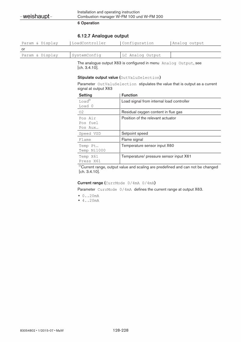
Installation and operating instructionCombustion manager W-FM 100 und W-FM 2006 Operation
83054802 1/2015-07 MaW 128-228
6.12.7 Analogue outputParam & Display LoadController Configuration Analog output
orParam & Display SystemConfig LC Analog Output
The analogue output X63 is configured in menu Analog Output, see[ch. 3.4.10].
Stipulate output value (OutValuSelection)
Parameter OutValuSelection stipulates the value that is output as a currentsignal at output X63
Setting FunctionLoad(1
Load 0Load signal from internal load controller
O2 Residual oxygen content in flue gasPos AirPos fuelPos Aux…
Position of the relevant actuator
Speed VSD Setpoint speedFlame Flame signalTemp Pt…Temp Ni1000
Temperature sensor input X60
Temp X61Press X61
Temperature/ pressure sensor input X61
€€
(1Current range, output value and scaling are predefined and can not be changed[ch. 3.4.10].
Current range (CurrMode 0/4mA 0/4mA)
Parameter CurrMode 0/4mA defines the current range at output X63.0..20mA4..20mA

Installation and operating instructionCombustion manager W-FM 100 und W-FM 2006 Operation
83054802 1/2015-07 MaW 129-228
Output valuesDefines the internal value (%, °C, bar or degree of angle) at which 20 mA flow atoutput X63.
Setting FunctionScale20mA prec Internal percentage value (0 ... 999.9 %) at 20 mA, valid
for:Load 0O2Speed VSDFlame
Scale20mA temp Temperature at input X60/X61 (0 ... 2000 °C) at 20 mA,valid for:Temp Pt1000 / Temp Ni1000 / Temp Pt100Temp X61
Press X61 Pressure sensor at input X61 (0 ... 99.9 bar) at 20 mA,valid for Press X61.
Scale20mA angle Actuator position in degree of angle (0 ... 90°) at 20 mA,valid for:Pos AirPos fuelPos Aux…
Scaling (Scale 0/4mA)
Parameter Scale 0/4mA defines the internal value for the lower current limit.Depending on parameter CurrMode 0/4mA 4 mA or 0 mA flow at the value set. The relative value in percent refers to the output value set (Scale20mA … /Press X61).

Installation and operating instructionCombustion manager W-FM 100 und W-FM 2006 Operation
83054802 1/2015-07 MaW 130-228
6.12.8 Control parameters of internal load controllerParam & Display LoadController ControlParam ContrlParamList StandardParam
PPart (Xp)IPart (Tn)DPart (Tv)
To be able to use the internal load controller, it must be activated in parameterLC_OptgMode, see [ch. 6.12.2].The control behaviour of the load controller is set in menu ControlParamList .Under StandardParam one of five standard parameter sets or the PID para-meter set from the adaption can be selected.
Parameter setStandardParam
P-Part Xp [%] I-Part Tn[s] D-Part Tv [s]
Adaption Values determined during adaption [ch. 6.12.15].##
very fast 42.5 68 12fast 14.5 77 14normal 6.4 136 24slow 4.7 250 44very slow 3.4 273 48
##
Adapting control parametersThe PID parameter can be altered manually.
Parameters FunctionPPart (Xp) Proportional partIPart (Tn) Integral part (integral action time)DPart (Tv) Differential part (derivative action time)
Xp too small Xp too large Tn, Tv too small Tn, Tv too large

Installation and operating instructionCombustion manager W-FM 100 und W-FM 2006 Operation
83054802 1/2015-07 MaW 131-228
6.12.9 Control variable calmingParam & Display LoadController ControlParam MinActuatorStep
In modulating operation, parameter MinActuatorStep determines the minimumcorrecting element step. The minimum correcting element step is used as control variable calming. If the dif-ference between the new control variable and the current control variable is lessthan MinActuatorStep, the current control variable is maintained. The actuatorsare less stressed due to the reduced drive impulses.If the control variable calming is too great, the control becomes inaccurate or be-gins to oscillate.
6.12.10 Fault signal suppressionParam & Display LoadController ControlParam SW_FilterTmeCon
Parameter SW_FilterTmeCon weakens actual value fault signals.Actual value fault signals mainly affect the D part. If the filter time selected is toolong it affects the actual value and negatively affects the control accuracy .Set the filter time to 2 … 4 seconds for automatic adaption. If the time selected istoo long the automatic adaption can be interrupt. On steam plants, increase the fil-ter time after the adaption to 6 … 8 seconds.
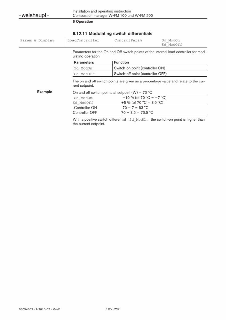
Installation and operating instructionCombustion manager W-FM 100 und W-FM 2006 Operation
83054802 1/2015-07 MaW 132-228
6.12.11 Modulating switch differentialsParam & Display LoadController ControlParam Sd_ModOn
Sd_ModOff
Parameters for the On and Off switch points of the internal load controller for mod-ulating operation.
Parameters FunctionSd_ModOn Switch-on point (controller ON)Sd_ModOFF Switch-off point (controller OFF)
The on and off switch points are given as a percentage value and relate to the cur-rent setpoint.
Example##
On and off switch points at setpoint (W) = 70 °CSd_ModOn: −10 % (of 70 °C = −7 °C)
##
Sd_ModOff +5 % (of 70 °C = 3.5 °C)Controller ON 70 − 7 = 63 °C
##
Controller OFF 70 + 3.5 = 73.5 °C
With a positive switch differential Sd_ModOn the switch-on point is higher thanthe current setpoint.

Installation and operating instructionCombustion manager W-FM 100 und W-FM 2006 Operation
83054802 1/2015-07 MaW 133-228
6.12.12 Multi-stage switch differentials and switch thresholds
6.12.12.1 Multi-stage switch differentialsParam & Display LoadController ControlParam Sd_Stage1On
Sd_Stage1OffSd_Stage2OffSd_Stage3Off
Parameters for the On and Off switch points of the internal load controller for multi-stage operation.
Parameters FunctionSd_Stage1On Switch-on point (controller ON)Sd_Stage1Off Switch-off point stage 1 (controller OFF)Sd_Stage2Off Switch-off point stage 2Sd_Stage3Off Switch-off point stage 3
The on and off switch points are given as a percentage value and relate to the cur-rent setpoint.
Example On and off switch points at setpoint (W) = 70 °C##
Sd_Stage1On = −10 % (of 70 °C = −7 °C)Sd_Stage1Off = +5 % (of 70 °C = 3.5 °C)Sd_Stage2Off = +2 % (of 70 °C = 1.4 °C)Sd_Stage3Off = +1 % (of 70 °C = 0.7 °C)
##
Stage 1 (controller) ON 70 − 7 = 63 °C##
Stage 1 (controller) OFF 70 + 3.5 = 73.5 °CStage 2 OFF 70 + 1.4 = 71.4 °CStage 3 OFF 70 + 0.7 = 70.7 °C
##
If stage 1 exceeds Sd_Stage3Off before stage 3 has switched, the controllerswitches off.
Threshold for stage 2 not achievedStage 1 already switches off at: Setpoint (W) + Sd_Stage3Off
Threshold for stage 2 and 3 notachievedStage 1 switches off at: Setpoint (W) + Sd_Stage1Off
Sd_Stage1Off
Sd_Stage2Off
Sd_Stage3Off
Setpoint (W)Sd_Stage1On
Stage 1 (controller ON)
Stage 2
Stage 3

Installation and operating instructionCombustion manager W-FM 100 und W-FM 2006 Operation
83054802 1/2015-07 MaW 134-228
6.12.12.2 Multi-stage switch thresholdParam & Display LoadController ControlParam ThreshStage2On
ThreshStage3On
Parameter ThreshStage…On stipulates the switch threshold for stage 2 andstage 3. The switch threshold influences the switching of the stages.If the actual value drops below Sd_Stage1On the W-FM forms the integral fromcontrol deviation x time. When the value reaches ThreshStage2On (Q2)stage 2 switches.If the value reaches ThreshStage3On (Q3) before Sd_Stage1On is notachieved, stage 3 switches.
Q2 Q2Q3
Sd_Stage1Off
Sd_Stage2Off
Sd_Stage3Off
Setpoint (W)Sd_Stage1On
Stage 1 (controller ON)
Stage 2
Stage 3
6.12.12.3 Low impact startIf a three stage burner is to be operated two stage with low impact start:
Set parameter Sd_Stage2Off and Sd_Stage1Off to the same value.When Sd_Stage2Off is reached, the W-FM initiates a shutdown.Set parameter ThreshStage2On to 0.if the W-FM releases the load control, stage 2 switches immediately. Stage 3only switches once the switch threshold (Q3) has been reached.

Installation and operating instructionCombustion manager W-FM 100 und W-FM 2006 Operation
83054802 1/2015-07 MaW 135-228
6.12.13 Temperature sensorParam & Display LoadController ControlParam TL_ThreshOff
TL_SD_On
orParam & Display SystemConfig TempLimiter TL_ThreshOff
TL_SD_On
The temperature monitor is only activated in conjunction with the sensors Pt100,Pt1000 or Ni1000, see [ch. 6.12.3].Parameter TL_ThreshOff stipulates the switch threshold for the temperaturemonitor.Parameter TL_SD_On stipulates the switch-on hysteresis. The switch-on hyster-esis is given as a percentage value and relates to the switch threshold for the tem-perature monitor.
Example TL_ThreshOff = 80 °C If the temperature exceeds thethreshold, the W-FM initiates a shut-down and block the burner start.
TL_SD_On = −10 % 80 °C − (80 °C x 0.1) = 72 °C
If the temperature drops below theswitch-on hysteresis, the W-FM re-moves the block.

Installation and operating instructionCombustion manager W-FM 100 und W-FM 2006 Operation
83054802 1/2015-07 MaW 136-228
6.12.14 Boiler cold start functionParam & Display LoadController ControlParam ColdStart
The boiler cold start function reduces the thermal load of the boiler during burnerstart.If the boiler cold start function is activated and if the boiler temperatures is belowthe switch-on threshold set for the boiler cold start function at burner start, the W-FM carries out a cold start sequence. The burner starts with the lowest burner ca-pacity. The capacity is increased, either after the residence time set or when theboiler temperature exceeds the next setpoint step. When the boiler temperaturereaches the switch-off threshold set, the W-FM stops the cold start sequence andthe load control is activated.
ThresholdOff
Setpoint (W)
Step Setp_...Threshold_On
Boiler temperature
Step capacityPartial load
Stage 3
Stage 2
Stage 1
Maxtime_mod
Maxtime_stage
Temperature
Modulating capacity
Burner Off
Burner Off
Multi-stage capacity

Installation and operating instructionCombustion manager W-FM 100 und W-FM 2006 Operation
83054802 1/2015-07 MaW 137-228
Activate boiler cold start function (ColdStartOn)
Parameter ColdStartOn activates or deactivates the boiler cold start function.
Switch-on threshold (ThresholdOn)
Parameter ThresholdOn stipulates the switch-on threshold for the boiler coldstart function.If the boiler temperature is below the switch-on threshold at heat demand, the W-FM carries out the cold start sequence.The switch-on threshold is given as a percent value and relates to the current set-point W1 or W2. If an additional sensor is connected to input X60, the switch-onthreshold relates to the setpoint set under Setp AddSensor .
Load stage (StageLoad)
Parameter StageLoad stipulates the stage for load increase in modulating oper-ation.When the boiler temperature reaches the next setpoint step StageSetp_…, theburner capacity increases by the percentage point set.If the next setpoint step is not reached, the capacity increases after the residencetime Maxtme_… set has elapsed.
Setpoint stage (StageSetp_…)
The parameters stipulate the step for the setpoint increase.
Parameters FunctionStageSetp_Mod Setpoint step for modulating operationStageSetp_Stage Setpoint step for multi-stage operation
The setpoint step is given as a percentage value and relates to to current set-point W1 or W2. If an additional sensor is connected to input X60, the switch-onthreshold relates to the setpoint set under Setp AddSensor .When the boiler temperature reaches the current cold start setpoint, the cold startsetpoint increases by the step set.In addition, the burner capacity in modulating operation increases by the load step,in multi-stage operation the next stage switches.
Residence time (MaxTme_…)
The residence time stipulates the minimum time after which the burner capacity isincreased.If the boiler temperature does not reach the current cold start setpoint after thistime has elapsed, the burner capacity is increased and the time starts again. Inmodulating operation, the burner capacity increases by the load step set, in multi-stage operation the next stage switches.
Parameters FunctionMaxTmeMod Minimum time for modulating operation after which the
burner capacity is increased.MaxTmeStage Minimum time for multi-stage operation after which the
next stage switches, provided that the stages have beenreleased in parameter Release Stages.

Installation and operating instructionCombustion manager W-FM 100 und W-FM 2006 Operation
83054802 1/2015-07 MaW 138-228
Switch-off threshold (ThresholdOff)
Parameter ThresholdOff stipulates the switch-off threshold for the boiler coldstart function.The switch-off threshold is given as a percent value and relates to the current set-point W1 or W2. If an additional sensor is connected to input X60, the switch-onthreshold relates to the setpoint set under Setp AddSensor . When the boiler temperature reaches the switch-off threshold set, the W-FM stopsthe cold start sequence and the load control is activated.
Additional sensor (AdditionalSens)
If a pressure sensor is connected to input X61, the cold start function requires anadditional sensor at input X60 [ch. 3.3.20].The additional sensor connected is defined in parameter AdditionalSens .If the additional sensor has been defined, the setpoint set under Setp AddSensor is deemed as the reference value for the boiler cold start function.
Temperature at additional sensor (Temp. ColdStart)
Parameter Temp. ColdStart shows the current temperature at the additionalsensor.
Setpoint for additional sensor (Setp AddSensor)
Parameter Setp AddSensor stipulates the setpoint for the boiler cold startfunction if an additional sensor is defined.
Release stages (Release Stages)
In parameter Release Stages , stage 2 and stage 3 can be blocked for boilercold start function. The parameter is only effective in multi-stage operation.
Setting FunctionNo release Boiler cold start function is only carried out with stage 1.
Stage 2 and stage 3 are blocked for the boiler cold startfunction. Parameters MaxTmeStage andStageSetp_Stage have no effect.
Release The boiler cold start function starts in stage 1. The nextstage switches, when the boiler temperature reaches thecurrent cold start setpoint or the residence time is ex-ceeded.

Installation and operating instructionCombustion manager W-FM 100 und W-FM 2006 Operation
83054802 1/2015-07 MaW 139-228
6.12.15 AdaptionParam & Display LoadController Adaption StartAdaption
AdaptionLoad
Start adaptionThe load controller starts automatic adaption via parameter StartAdaption.During adaption, the load controller identifies the controlled system and generatesthe PID parameters from the data determined.Adaption is only possible in modulating operation. It is possible to start in manual orautomatic operation, independent of operating status (burner ON, OFF orStandby).During adaption, the filter time SW_FilterTmeCon of fault signal suppressionmust be 2 … 4 seconds [ch. 6.12.10].Automatic adaption passes through 4 phases.
Phase FunctionTemp setback Reduces actual value to 5 % below setpoint.Stabilisationphase
The course of the actual value is evaluated for 5 minutes.If severe fluctuations occur, the time increases to10 minutes.
Heating The course of the actual value during heat-up phase isdetermined.
Adaption ok Adaption completed successfully, the PID parametersare calculated.
Adaption capacityParameter AdaptionLoad stipulates the burner capacity for automatic adaption.The adaption capacity should be chosen as large as possible. If the adaption in fullload (100 %) is interrupted due to insufficient heat demand, the adaption capacitycan be reduced by up to 40 %. If the adaption capacity selected is insufficient, the setpoint temperature will not bereached and the adaption will be aborted.

Installation and operating instructionCombustion manager W-FM 100 und W-FM 2006 Operation
83054802 1/2015-07 MaW 140-228
6.13 Actuators
6.13.1 AddressingParam & Display Actuators Addressing
If only one actuator is replaced, the W-FM addresses the new actuator automatic-ally.If two or more actuators are replaced at the same time, each new actuator has tobe addressed manually.
A B
1
2
3
1 Addressing key2 LED3 JumperA without Bus terminationB with Bus termination
Bus terminationOn the last actuator or at the O2 module, the bus termination must be set via ajumper [ch. ].
Addressing the actuatorRemove actuator cover.In menu Param & Display / Actuator , select parameter Addressingand confirm with [ENTER].Select the relevant actuator using the dial knob:1 AirActuator: Air damper2 GasActuator (Oil): Gas butterfly valve3 OilActuator: Oil quantity regulator4 AuxActuator: Mixing head5 AuxActuator2: Auxiliary actuator for special applications6 AuxActuator3: Auxiliary actuator for special applications
Confirm with [ENTER].The text Start address assignment with ENTER appears.Start address assignment with [ENTER].Text Address assignment being carried out changes to Pleasepress button on actuator after approx. 5 seconds.Press addressing key on actuator.LED on actuator flashes continually.Text Address assignment carried out successfully appears.LED on actuator displays flashing codes.Exit address assignment using [esc]

Installation and operating instructionCombustion manager W-FM 100 und W-FM 2006 Operation
83054802 1/2015-07 MaW 141-228
Flashing codes
LED DescriptionContinually ON unaddressed actuatorFlashing continually addressing being carried outFlashing codes with pause Actuator is addressed:
1 impulse: Air damper actuator2 impulses: Gas butterfly valve actuator3 impulses: Oil quantity regulator actuator4 impulses: Mixing head actuator5 impulses: Actuator Aux2 (W-FM 200 only)6 impulses: Actuator Aux3
Delete addressingPress addressing key on actuator for 10 seconds.The LED on the actuator changes to continually ON.
6.13.2 Delete curvesParam & Display Actuators DeleteCurves
Parameter DeleteCurves deletes the compound curves of all actuators, is re-quired to change the rotation direction in the OEM level.
6.13.3 Position controlParam & Display SystemConfig Allowed Pot.diff
Each actuator transmits two independent position signals to the W-FM. The W-FMcompares the position signals to the setpoint position. The W-FM also comparesthe two position signals. Parameter Allowed Pot.diff stipulates the max-imum permissible deviation between the position signals.The W-FM initiates a lockout, if:
an actuator does not reach the setpoint position,the position signals exceed the difference set under Allowed Pot.diff .
Recommended setting: 15 (equal to 1.5°)
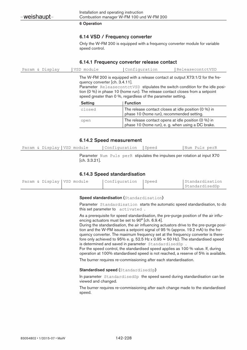
Installation and operating instructionCombustion manager W-FM 100 und W-FM 2006 Operation
83054802 1/2015-07 MaW 142-228
6.14 VSD / Frequency converterOnly the W-FM 200 is equipped with a frequency converter module for variablespeed control.
6.14.1 Frequency converter release contactParam & Display VSD module Configuration ReleasecontctVSD
The W-FM 200 is equipped with a release contact at output X73:1/2 for the fre-quency converter [ch. 3.4.11]. Parameter ReleasecontctVSD stipulates the switch condition for the idle posi-tion (0 %) in phase 10 (home run). The release contact closes from a setpointspeed greater than 0 %, regardless of the parameter setting.
Setting Functionclosed The release contact closes at idle position (0 %) in
phase 10 (home run), recommended setting.open The release contact opens at idle position (0 %) in
phase 10 (home run), e. g. when using a DC brake.
6.14.2 Speed measurementParam & Display VSD module Configuration Speed Num Puls perR
Parameter Num Puls perR stipulates the impulses per rotation at input X70[ch. 3.3.21].
6.14.3 Speed standardisationParam & Display VSD module Configuration Speed Standardisation
StandardisedSp
Speed standardisation (Standardisation)
Parameter Standardisation starts the automatic speed standardisation, to dothis set parameter to activated .As a prerequisite for speed standardisation, the pre-purge position of the air influ-encing actuators must be set to 90° [ch. 6.9.4].During the standardisation, the air influencing actuators drive to the pre-purge posi-tion and the W-FM issues a setpoint signal of 95 % (approx. 19.2 mA) to the fre-quency converter. The maximum frequency set at the frequency converter is there-fore only achieved to 95% e. g. 52.5 Hz x 0.95 ≈ 50 Hz). The standardised speedis determined and saved in parameter StandardisedSp .For the speed control, the standardised speed applies as 100 % value. If, duringoperation at 100% standardised speed is not reached, a reserve of 5% is available.The burner requires re-commissioning after each standardisation.
Standardised speed (StandardisedSp)
In parameter StandardisedSp the speed saved during standardisation can beviewed and changed.The burner requires re-commissioning after each change made to the standardisedspeed.
Installation and operating instructionCombustion manager W-FM 100 und W-FM 2006 Operation
83054802 1/2015-07 MaW 143-228
6.14.4 Actual speedParam & Display VSD module Configuration Speed Absolute speed
orParam & Display VSD module Process Data Absolute speed
Absolute speedParameter Absolute speed indicates the current speeddetected.
6.14.5 Setpoint outputParam & Display VSD module Configuration Speed Setpoint Output
Parameter Setpoint Output stipulates the current signal, which controls thefrequency converter [ch. 3.4.11]. The current signal from the W-FM must be matched to the frequency converter.
Setting Function4..20 mA Current signal with load monitoring (standard)0..20 mA Current signal without load monitoring
6.14.6 Speed deviationParam & Display VSD module Process Data
The process data can be found in the volatile memory and are reset during reset orpower failure.
Parameters FunctionMax Stat Dev Shows the maximum speed deviation when changing a
control variable in modulating operation.Max Dyn Dev Shows the maximum speed deviation between actual
speed and setpoint speed when accelerating.Num Dev >0.3% Number of speed deviations when changing a control
variable with a difference greater than 0.3%.Num Dev >0.5% Number of speed deviations when changing a control
variable with a difference greater than 0.5%.

Installation and operating instructionCombustion manager W-FM 100 und W-FM 2006 Operation
83054802 1/2015-07 MaW 144-228
6.15 Flue gas recirculationOnly the W-FM 200 type LMV52.4… is equipped with the flue gas recirculation(FGR) function.Before the flue gas recirculation can be adjusted, burner commissioning with theFGR damper closed must be carried out. On burners with separate combustion air fan, the air dampers (Aux2) in front of theFGR connection housing must also be slightly closed [ch. 6.15.1.2].The FGR function is fuel specific and must be set separately for each fuel on dualfuel burners.If the FGR function is only used for one fuel on dual fuel burners, the actuator posi-tion (Aux3) for the other fuel must be set to 0° (closed) in all load points and spe-cial positions.
6.15.1 FGR function
6.15.1.1 Fan on burnerThrough a pipeline, the fan draws the flue gas from the flue gas pipe. A flue gasdamper (FGR damper) 1 in the pipeline meters the recirculated flue gas quantity.The FGR damper is driven load dependent, in compound by the actuator (Aux3).The recirculated flue gas quantity dependents on the position of the FGRdamper 1 and the negative pressure in the FGR connector housing 2. With suffi-cient negative pressure the FGR damper operates up to an opening angle of ap-prox. 60°, above this the recirculated flue gas quantity increases marginally. If therecirculated flue gas quantity is insufficient to reach the NOX limit value, the negat-ive pressure in the FGR connector housing has to be increased, to do this either:
close air damper 3 further,increase speed 4,open mixing head 5 further.
The air quantity required for combustion must not be changed, to achieve this al-ternately change the actuator positions and speed.

Installation and operating instructionCombustion manager W-FM 100 und W-FM 2006 Operation
83054802 1/2015-07 MaW 145-228
M
M
M
M
M
W-FM 200
M
W-FM 200
+
1
3
4 5
2
Example Actuator Change ReactionAir damper CLOSED decreased combustion air (-)
increased negative pressure (+)increased flue gas recirculation (+)
Speed Increase increased combustion air (+)increased negative pressure (+)increased flue gas recirculation (+)
FGR damper CLOSED decreased flue gas recirculation (-)
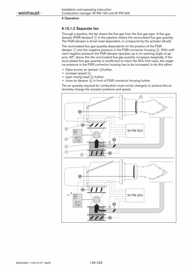
Installation and operating instructionCombustion manager W-FM 100 und W-FM 2006 Operation
83054802 1/2015-07 MaW 146-228
6.15.1.2 Separate fanThrough a pipeline, the fan draws the flue gas from the flue gas pipe. A flue gasdamper (FGR damper) 1 in the pipeline meters the recirculated flue gas quantity.The FGR damper is driven load dependent, in compound by the actuator (Aux3).The recirculated flue gas quantity dependents on the position of the FGRdamper 1 and the negative pressure in the FGR connector housing 2. With suffi-cient negative pressure the FGR damper operates up to an opening angle of ap-prox. 60°, above this the recirculated flue gas quantity increases marginally. If therecirculated flue gas quantity is insufficient to reach the NOX limit value, the negat-ive pressure in the FGR connector housing has to be increased, to do this either:
Open burner air damper 3further,increase speed 4,open mixing head 5 further,close air damper 6 in front of FGR connector housing further.
The air quantity required for combustion must not be changed, to achieve this al-ternately change the actuator positions and speed.
M
M
M
M
M
M
M
M
+
W-FM 200
W-FM 200
1
2
3
4
5
6
Installation and operating instructionCombustion manager W-FM 100 und W-FM 2006 Operation
83054802 1/2015-07 MaW 147-228
Example Actuator Change ReactionAir dampers infront of FGR con-nector housing
CLOSED decreased combustion air (-)increased negative pressure (+)increased flue gas recirculation (+)
Speed Increase increased combustion air (+)increased negative pressure (+)increased flue gas recirculation (+)
FGR damper CLOSED decreased flue gas recirculation (-)
Initial commissioning without FGRTo ensure sufficient negative pressure for flue gas recirculation, slightly close theair dampers in front of the FGR connector housing at each load point during the ini-tial commissioning without FGR.Once the combustion limit is determined and the excess air is set:
Close air dampers in front of FGR connector housing (Aux2) until the O2 contentreduces by approx. 0.4 % points.Increase the O2 content again to the previous value using the air influencing ac-tuators, whilst observing the flame stability.

Installation and operating instructionCombustion manager W-FM 100 und W-FM 2006 Operation
83054802 1/2015-07 MaW 148-228
6.15.2 FGR operating modeParam & Display Flue Gas Recirc. FGRMode
Parameter FGRMode stipulates how and when the actuator Aux3 is controlledduring flue gas recirculation.
Setting FunctionAux3onCurve Actuator Aux3 drives on its programmed compound curve.
Not recommended for FGR function.If there is no flue gas recirculation installed, select this setting if the actuator is tobe used for another function.
time Actuator Aux3 initially remains in ignition position in phase 60 (operating posi-tion 1). Only once the residence time set under DelaytimeFGR… has elapsedwill the actuator drive on the compound curve [ch. 6.15.5].
Temperature Actuator Aux3 initially remains in ignition position in phase 60 (operating posi-tion 1). Once the FGR temperature sensor reaches the temperature set underThresholdFGR… will the actuator drive on the compound curve [ch. 6.15.5].Only for plant with FGR temperature sensor in the flue gas pipe.
^^
Temp.comp. Temperature compensated FGR function. Only with W-FM type LMV 52.4xx.During FGR commissioning the W-FM captures and saves the temperature at thetemperature sensor at each load point.If, during operation, the FGR temperature differs from the saved temperature, theW-FM recalculates the position for actuator Auxs3. Deviating from the compoundcurve, the actuator drives to the calculated position and compensates the temper-ature deviation.How much the temperature deviation affects the actuator position can be set inparameter FactorFGR… .The FGR minimum position is always maintained [ch. 6.15.8].In parameter DelaytimeFGR… the residence time for phase 60 (operating pos-ition 1) can be set [ch. 6.15.5].
^^
TCautoDeact Temperature compensated FGR function and automatic deactivation. Only withW-FM type LMV 52.4xx.As with Temp.comp., the W-FM also monitors the FGR temperature sensor.If a sensor fault occurs, the W-FM deactivates the FGR function and a warningappears in the display. Actuator Aux3 then drives to FGR minimum position[ch. 6.15.8].
^^
deactMinpos After ignition position, actuator Aux3 drives to FGR minimum position [ch. 6.15.8].The temperature at the FGR temperature sensors is not recorded, the displayshows xxxx.Operating mode for commissioning without FGR function, set FGR minimum pos-ition to 0° .
auto deact Do not select this operating mode.Parameter auto deact is automatically activated when a fault occurs in oper-ating mode TCautoDeact . Actuator Aux3 drives to FGR minimum positionand a warning appears in the display.
€€
The temperature compensated AFR function is not possible when O2 trim is activ-ated.

Installation and operating instructionCombustion manager W-FM 100 und W-FM 2006 Operation
83054802 1/2015-07 MaW 149-228
6.15.3 Define temperature sensorParam & Display Flue Gas Recirc. FGRsensor
The FGR sensor connected is defined in parameter FGRsensor .The FGR temperature sensor is connected to input X60 as standard [ch. 3.3.20]. For temperature compensated operation, the FGR temperature sensor should bepositioned as close as possible to the FGR damper.
Parameters FunctionX86PtNi1000 The temperature sensor connected to the O2 module is
also used for the FGR function [ch. 3.3.23].Not suitable for temperature compensated operation.
X60 Pt10000
X60 Ni1000
Ni1000 sensor at terminal X60:3/4Pt1000 sensor at terminal X60:3/4The corresponding sensor must not be defined in themenu Sensor Select of the load controller[ch. 6.12.3].
6.15.4 FGR sensor temperatureParam & Display Flue Gas Recirc. actTmpFGRsensor
Parameter actTmpFGRsensor shows the current temperature at the FGR tem-perature sensor.

Installation and operating instructionCombustion manager W-FM 100 und W-FM 2006 Operation
83054802 1/2015-07 MaW 150-228
6.15.5 FGR releaseParam & Display Flue Gas Recirc. ThresholdFGR…
DelaytimeFGR…
The parameters stipulate when the FGR function is released.After entering phase 60 (operating position 1) actuator Aux3 initially remains in igni-tion position. if the release criteria is met, Aux3 drives on the compound curve. Depending on the FGR operating mode set, release is either effective via the timeor the temperature at the FGR sensor.The release can be set separately for each fuel.
Parameters FunctionThresholdFGR GasThresholdFGR Oil
When the FGR sensor reaches the temperature set, theW-FM releases the FGR function. For this, the FGRsensor must be placed in the flue gas pipe or the FGRdamper must be slightly open in ignition position.Only for operating mode Temperature.
DelaytimeFGR GasDelaytimeFGR Oil
The W-FM releases the FGR function in phase 60 oncethe time set has elapsed. The time depends on the thewarm-up phase of the plant. Criteria is consistent capa-city and constant flue gas temperature.For operating mode:timeTemp.comp.TCautoDeact
recommended setting: 60 seconds
6.15.6 Temperature compensationParam & Display Flue Gas Recirc. FGR Factor Gas
FGR Factor Oil
During FGR commissioning the W-FM captures and saves the temperature at theFGR temperature sensor at each load point. If, during operation, the FGR temperat-ure differs from the saved temperature, the W-FM recalculates the position for ac-tuator Aux3. If the FGR sensor drops below the temperature saved the FGRdamper is closed further.Parameter FGR Factor … stipulates how much the temperature compensationaffects position of the FGR damper.With a factor of 100%, the temperature compensation is fully effective. With valuesbelow 100% the recirculated flue gas quantity is reduced.The parameter is only effective in operating modes:TCautoDeactTemp.comp.

Installation and operating instructionCombustion manager W-FM 100 und W-FM 2006 Operation
83054802 1/2015-07 MaW 151-228
6.15.7 Operating temperatureParam & Display Flue Gas Recirc. OperationTempGas
OperationTempOil
Parameter OperationTemp … displays the temperatures that were saved dur-ing temperature compensated commissioning.The temperature can be displayed at each load point. Invalid values or non-con-figured operating points are displayed with XXXX .
6.15.8 Position limit FGR damperThe position limit restricts the setting of the flue gas damper up and down.The Position limit is only effective in the temperature compensated operatingmodes:Temp.comp.TCautoDeact
FGR minimum position
Param & Display Flue Gas Recirc. FGR MinPos
Parameter FGR MinPos limits the closing angle and ensures a minimum flow.The minimum position is an absolute value (degree of angle) and applies to thewhole load range.The FGR damper drives to minimum position if:
the W-FM calculates a smaller closing angles for the temperature compensationthen is defined in FGR MinPos ,the operating mode deactMinpos or auto deact is activated.
FGR maximum position
Param & Display Flue Gas Recirc. FGR MaxPos Fact
Parameter FGR MaxPos Fact limits the opening angle upwards. The maximumposition is given as a percentage value and relates to the current position of thecompound curve (Aux3).

Installation and operating instructionCombustion manager W-FM 100 und W-FM 2006 Operation
83054802 1/2015-07 MaW 152-228
6.16 Data backup
6.16.1 Backup copyUpdating Param backup BackupInfo
LMV5x > AZLAZL > LMV5x
Information for backupMenu BackupInfo displays the date, time and the contents of the last databackup.
Parameters FunctionDate Displays the date of the last backup copy.TimeOfDay Displays the time of the last backup copy.BU included? Indicates whether the information from the W-FM has
been transferred without errors.AZL included? Indicates whether a display and operating unit was con-
nected during the last backup.ACT… included? Shows the actuatros connected during the last data
back-up.VSD included? Indicates whether a frequency converter module was
saved in the backup copy.O2 included? Indicates whether an O2 module was saved in the
backup copy.
Creating a backup copyParameter LMV5x > AZL creates a backup copy of the W-FM in the displayand operating unit (ABE) The existing data is overwritten.The data from the W-FM can be backed up to any ABE.
Select parameter LMV5x > AZL and confirm with [ENTER].Start process with [ENTER].Exit level using the [esc] key.
Param & DisplayUpdatingEnter PWDeactivate PW
Param backupLoad SW from PC
BackupInfoLMV5x > AZLAZL > LMV5xLMV5x > AZL
Start processwith ENTERAbort with ESC
Parmeters beingupdatedAbort with ESCBackup being
createdParameters weresavedContinue w ESC
Param backupLoad SW from PC

Installation and operating instructionCombustion manager W-FM 100 und W-FM 2006 Operation
83054802 1/2015-07 MaW 153-228
Load backup copy to W-FMParameter AZL > LMV5x transfers the data of the display and operating unit(ABE) to the W-FM.The existing data is overwritten.The data can only be transferred to the W-FM if either:
the burner identification is identical in the W-FM and in the backup copy(backup) [ch. 6.4.10],the W-FM does not contain a burner identification.Select parameter AZL > LMV5x and confirm with [ENTER].Start process with [ENTER].Exit level using the [esc] key.The W-FM goes to lockout and displays the reason for the lockout.Exit display using the [esc] key.Reset burner using the [ENTER] key.
Param & DisplayUpdatingEnter PWDeactivate PW
Param backupLoad SW from PC
Parmeters beingupdatedAbort with ESCBackup Restore
running!
BackupInfoLMV5x > AZLAZL > LMV5x
AZL > LMV5xStart processwith ENTERAbort with ESC
ParametersBackup Restore
Backup RestorecompletedParameters! GG: complete
LockoutDo you want toreset system usingENTER?
Reset
6.16.2 Updating softwareUpdating Load_SW_from_PC
ParameterLoad_SW_from_PC updates the software of the display and operatingunit (ABE). To do this, a PC with ASC450 Software must be connected at inter-face COM 1, see [ch. 6.6.1]. The current file is available from Weishaupt.

Installation and operating instructionCombustion manager W-FM 100 und W-FM 2006 Operation
83054802 1/2015-07 MaW 154-228
6.17 TÜV Test
6.17.1 Flame failureTÜV Test LossFlameTest
Parameter LossFlameTest interrupts the flame signal and it is possible tocheck if the W-FM initiates a lockout.
6.17.2 Safety temperature limiterTÜV Test SLT Test
SLTTestload ModSLTTestload Stg
These parameters can be used to check if the safety temperature limiter (STL) re-sponds.Parameter SLT Test generates a heat demand, deactivates the internal temper-ature monitor and the burner drives to the load or stage set under SLTTestload….

Installation and operating instructionCombustion manager W-FM 100 und W-FM 2007 Commissioning
83054802 1/2015-07 MaW 155-228
7 Commissioning
7.1 PrerequisiteCommissioning must only be carried out by qualified personnel.Only correctly carried out commissioning ensures the operational safety.Observe the prerequisites for commissioning in the installation and operatingmanual of the burner. This document contains detailed information about:
general installation regulations,nozzle selection,connecting measuring devices,replacing filter inserts,checking the gas connection pressure,carrying out soundness test,venting the gas valve train,setting the gas pressure regulator,pre-setting the pressure switch.
7.1.1 Adapting the motor to the frequency converter
Frequency converter fitted to burnerIf the frequency converter is fitted to the burner motor, the parameters have beenmatched to the motor and motor adaption is therefore not required.
Separate frequency converterOn burners with separate frequency converter, the automatic motor adaptationmust be carried out on the frequency converter. For this, the motor parameters inthe frequency converter must match the specifications on the nameplate of the mo-tor. Procedure for automatic motor adaptation see product manual for frequencyconverter.Separate frequency converter, which have been supplied with the burner, contain adefault parameter set a are supplied with a parameter list (MCT 10 Set-up Soft-ware …). Automatic motor adaptation also has to be carried out in this instance.

Installation and operating instructionCombustion manager W-FM 100 und W-FM 2007 Commissioning
83054802 1/2015-07 MaW 156-228
7.2 Adjusting the burnerIn addition to this chapter, the information about adjustment in installation and oper-ating manual of the burner should be observed. This document contains detailed in-formation about:
speeds (in in conjunction with frequency converter),pump pressure,flow and return pressure,default settings,mixing pressure.
7.2.1 Preparatory measuresIn addition to this chapter, the information about adjustment in installation and oper-ating manual of the burner should be observed.
PrerequisiteRemove mixing head drive rod (only on burners with adjustable mixing head).Set fuel selection switch to Gas (only on dual fuel burners with heavy oil).Switch on voltage supply.
1. Switch off burnerThe ABE is in OperationalStat in the sub menu NormalOperation and dis-plays current values.
Exit level using the [esc] key.Select ManualOperation.Select Autom/Manual/Off.Set Burner Off.The burner switches off.Exit level using the [esc] key.
2. Enter passwordSelect Param & Display.Select Access with HE (password for heating engineer).Enter HE password using dial knob and confirm with [ENTER] [ch. 6.2.1].
3. Check drive rod of mixing headOnly on burners with adjustable mixing head.
Isolate burner motor from voltage supply.Prevents fan starting during this step.Select RatioControl.Select GasSettings or OilSettings.Select SpecialPositions.Select HomePos.Select HomePosAux1 and set 0.0°.Refit drive rod and check stop (play 1 … 2 mm).Remove drive rod again.Select HomePosAux1 and set 90.0°.Refit drive rod and check stop (play 1 … 2 mm).Return HomePosAux1 to 0.0° setting.Reconnect voltage to burner motor.
Installation and operating instructionCombustion manager W-FM 100 und W-FM 2007 Commissioning
83054802 1/2015-07 MaW 157-228
4. Select fuelDual fuel burners only.Fuel can be selected via:
external fuel selection switch,the display and operating unit (ABE),building management system (BMS).
The fuel selector switch has priority over fuel selection via the display and operatingunit (ABE) or building management system (BMS).
Select fuel via ABE:Select Operation.Select Fuel.Select FuelSelect.Select Fuel using the dial knob and confirm with [ENTER].Exit level using the [esc] key.
7.2.1.1 Carry out speed standardisationOnly on burners which are equipped with separate frequency converter[ch. 6.14.3]. On dual fuel burner, standardisation should only be carried out during the commis-sioning of the first fuel. The burner requires re-commissioning after each standard-isation.Skip this step on burners without frequency converter.
Select Param & Display.Select VSD module.Select Configuration.Select Speed.Select Standardisation.Select activated using the dial knob and confirm with [ENTER].

Installation and operating instructionCombustion manager W-FM 100 und W-FM 2007 Commissioning
83054802 1/2015-07 MaW 158-228
7.2.1.2 O2 module presettingOnly for burners which are equipped with an O2 module.Skip these steps on burners without O2 module.
1. Check configuration of O2 moduleSelect Param & Display.Select O2 Module.Select Configuration.Check settings of the following parameters:O2 Sensor: Sensor used [ch. 6.10.7].SupAirTempSens: Pt1000 or Ni1000, if connected [ch. 3.3.24],FlueGasTempSens: Pt1000 or Ni1000, if connected [ch. 3.3.23],MaxTempFlGas…: Pre-setting 400 °C [ch. 6.10.10].
Exit Configuration level using [esc].
2. Check O2 sensor temperatureMonitor sensor temperature regularly during heat up phase.
Select Process Data.Select parameter QGO SensorTemp and check sensor temperature[ch. 6.10.20].Operating temperature: 700 ± 15 °C.Exit level O2 Module , press [esc] twice.
3. Deactivating O2 trimDeactivate the O2 trim prior to commissioning the compound curves. Deactivate theO2 trim for both fuels (oil and gas) [ch. 6.10.1].
Select O2Control/Alarm .Select GasSettings or OilSettings.Select OptgMode.Select man deact using dial knob and confirm with [ENTER].Exit level OptgMode using [esc].
4. Define fuel typeDefine the fuel type for both fuels (gas and oil) on dual fuel burners [ch. 6.10.6].
Select GasSettings or OilSettings.Select Type of fuel.Select fuel using the dial knob and confirm with [ENTER].Exit level O2Control/Alarm , press [esc] three times.
Installation and operating instructionCombustion manager W-FM 100 und W-FM 2007 Commissioning
83054802 1/2015-07 MaW 159-228
7.2.1.3 Deactivate flue gas recirculationOnly for burners which are equipped with flue gas recirculation.Skip this step on burners without flue gas recirculation.Deactivate flue gas recirculation prior to commissioning the compound curves[ch. 6.15.2].
Select Param & Display.Select Flue Gas Recirc..Select FGRMode.Select deactMinpos using dial knob and confirm with [ENTER].Exit level FGRModeusing [esc].Select FGR MinPos.Set 0° using dial knob and confirm with [ENTER].Exit level Flue Gas Recirc. , press [esc] three time.

Installation and operating instructionCombustion manager W-FM 100 und W-FM 2007 Commissioning
83054802 1/2015-07 MaW 160-228
7.2.2 Adjusting gas side
PrerequisiteOpen gas isolating valve.Pressure in gas valve train increases.Close isolating valve.
1. Check load limitsSelect RatioControl.Select GasSettings.Select LoadLimits.Select MinLoadGas and set 0.0%.Select MaxLoadGas and set 100%.Use [esc] key to return to the display LoadLimits.
2. Check ignition positionSelect SpecialPositions.Select IgnitionPos.Select IgnitionPosGas (gas butterfly valve setting in ignition position).Check IgnPosGas , pre-setting values see installation and operating manual ofburner.Select IgnitionPosAux1 (auxiliary motor setting in ignition position).Check IgnitionPosAux1:
Standard: 0.0°3LN (multiflam): 18.0°
Select IgnitionPosVSD (speed in ignition position, only in conjunction withfrequency converter).Check IgnitionPosVSD.
50 Hz operation: 70% ≙ 35 Hz55 Hz operation: 63.6%≙ 35 Hz
Use [esc] key to return to the display IgnitionPos.

Installation and operating instructionCombustion manager W-FM 100 und W-FM 2007 Commissioning
83054802 1/2015-07 MaW 161-228
3. Check mixing pressure in ignition positionSelect ProgramStop.Select 36 IgnPos.Use [esc] key to return to the display with GasSettings.Select Autom/Manual/Off.Select Manual (Burner On).Check rotation direction of motor.The burner starts and stops in ignition position without flame formationCheck mixing pressure in ignition position, see installation and operating manualof burner.Standard: 1.0 … 2.0 mbar3LN (multiflam): 1.5 … 2 mbarIf necessary, adjust mixing pressure via air damper setting:
Select GasSettings.Select SpecialPositions.Select IgnitionPos.Select IgnitionPosAir and adjust.Use [esc] key to return to the display IgnitionPos.
4. Check gas valvesSet new program stop:
without ignition gas: 44 Interv 1with ignition gas: 52 Interv 2
Ensure that the valves open and close correctly.The burner tries to ignite.The low gas pressure switch is activated.
5. IgnitionOpen gas isolating valve.The burner restarts the function sequence.The burner ignites and the actuators stop in the ignition position.Pre-set setting pressure on pressure regulator taking the expected combustionchamber pressure into consideration, see installation and operating manual ofburner.Determine combustion values at ignition position.Set O2 content of approx. 4 … 5 % via gas butterfly valve setting (IgnitionPosGas).
6. Adjusting low gas pressure switch
DANGER
Risk of explosion due to falling gas supply pressureFlame failure can lead to explosion.
Set low gas pressure switch to 70 % of the setting pressure.

Installation and operating instructionCombustion manager W-FM 100 und W-FM 2007 Commissioning
83054802 1/2015-07 MaW 162-228
7. Set intermediate load pointsSet ProgramStop to deactivated.Use [esc] key to return to the display SpecialPositions.Select CurveParams.Press [ENTER] key.Point 1 is displayed.Check combustion values
Only in conjunction with O2 trimTo ensure O2 trim is possible across the entire load range, point 1 must be approx.50 % below partial load (point 2). Excess air in all load points must be 20 … 25 %.
Press [ENTER] key.Select Change point?.Select Actuator positions with start.Call up and change values with dial knob and [ENTER] key.
Only in conjunction with frequency converterReduce speed (VSD) step by step, whilst observing the combustion values andadjust via air damper setting (Air). Minimum speed (see table) must be main-tained.
Burner version Minimum speedNR 40 %LN, 1LN, 3LN 50 %
Exit point 1 using [esc] key and save with [ENTER] key.Press [esc] key.The menu displays Point, Manual and the current actuator positions.
In menu Point all load points can be adjusted.In menu point Manual the current burner rating can be adjusted manually.
Select Manual and confirm with [ENTER].Increase burner rating using dial knob whilst observing combustion values (ex-cess air) and flame stability.Set load point using [ENTER] key if either:
the O2 content in the flue gas increases to above 7 %,the CO content increases,the flame reaches the limit of stability.
The new load point is displayed in menu Point and can be adjusted.Correct combustion values via gas butterfly valve position (Fuel).Exit setting using [esc] and save with [ENTER].Exit load point using [esc].Repeat steps until full load (Load: 100) has been reached.

Installation and operating instructionCombustion manager W-FM 100 und W-FM 2007 Commissioning
83054802 1/2015-07 MaW 163-228
8. Adjust full loadWhen adjusting, the ratings data given by the boiler manufacturer and the capacitygraph of the burner should be observed.If the burner is equipped with an adjustable mixing head:
Set auxiliary actuator for mixing head (Aux1) to diagram, see installation and op-erating manual of burner. Adjust combustion values and, if necessary, speed (VSD) alternately via airdamper setting (Air).Depending on the burner observe:
Mixing head positionMixing pressure
Only in conjunction with frequency converterWhilst observing the the combustion values and flame stability, keep speed as lowas possible, but not less than 80%.
Calculate gas throughput (operating volume VB) required [ch. 7.10].Set the position of the gas butterfly valve (Fuel) to approx. 60 … 70° in the fullload point.Adjust setting pressure at the pressure regulator until gas throughput (VB) isachieved.Check combustion valuesDetermine combustion limit and set excess air [ch. 7.9].
Only in conjunction with flue gas recirculationIf the burner is later operated with flue gas recirculation, the recirculated flue gasreduces the excess air. Set excess air 25 % above the combustion limit to ensure sufficient combustion airduring the commissioning of flue gas recirculation.On burners with separate combustion air fan, the air dampers (Aux2) in front of theFGR connection housing must also be slightly closed [ch. 6.15.1.2].
Set excess air 25 % above the combustion limit.Close air dampers in front of FGR connector housing (Aux2) until the O2 contentreduces by approx. 0.4 % points.Increase the O2 content again to the previous value using the air influencing ac-tuators, whilst observing the flame stability.
Determine gas throughput again.If necessary adjust setting pressure at pressure regulator and reset excess air.
The setting pressure must not be altered once this work has been completed.

Installation and operating instructionCombustion manager W-FM 100 und W-FM 2007 Commissioning
83054802 1/2015-07 MaW 164-228
9. Re-define point 1Drive to point 1 in menu Point, whilst observing the combustion values.Check combustion values and correct if necessary.Carry out load apportionment [ch. 7.11].
To allow a reduction of MinLoad after commissioning, point 1 should be set belowthe required partial load.
10. Delete intermediate load pointsDelete all load points except for point 1 and full load (Load: 100).
When an intermediate load point is deleted, all points above this intermediate loadpoint are reduced by one number.
11. Set new intermediate load pointsStarting at point 1, set new load points until full load is achieved.
A maximum of 15 load points can be programmed.A minimum of 5 load points are required for modulating operation.
Only in conjunction with frequency converterTo ensure an even speed characteristic curve, the speed of the new load pointsshould not be altered.
Increase burner rating in menu Manual, whilst observing combustion values.Set new intermediate load point using [ENTER] key.Optimise combustion at intermediate load point via air damper setting (Air).Carry out load apportionment [ch. 7.11].Repeat steps until full load (Load: 100) has been reached.Exit level using the [esc] key.
12. Check start behaviourSwitch off and restart burner.Check start behaviour and if necessary correct ignition load setting.
If the ignition load setting has been altered:Re-check start behaviour.
Define partial loadSelect LoadLimits.Select MinLoad.Define and set partial load whilst:
Observe data provided by boiler manufacturer.Observe burner capacity graph.
Installation and operating instructionCombustion manager W-FM 100 und W-FM 2007 Commissioning
83054802 1/2015-07 MaW 165-228
13. Set burner to automatic operationExit level using the [esc] key.Select Autom/Manual/Off.Set Automatic.Exit level using the [esc] key.If necessary set load controller and nd O2 trim.
14. Data backupExit level using the [esc] key.The display shows Create parameter backup?.Start data backup by pressing [ENTER] key.The display shows Parameters are being updated and the Parameters have been saved.The values have been backed up from the combustion manager to the ABE.Exit level using the [esc] key.

Installation and operating instructionCombustion manager W-FM 100 und W-FM 2007 Commissioning
83054802 1/2015-07 MaW 166-228
7.2.3 Adjust modulation oil side
Prerequisite for fuel oil ELOpen oil shut off devices.
Prerequisite for medium and heavy fuel oil
DANGER
Danger of getting burned on oil carrying componentsThe oil carrying components are heat up by the line heating and hot oil and couldcause burns if touched.
Do not touch the components.
Observe the enclosed installation and operating manual for the oil preheater (PrintNo.18).Prior to adjusting ensure that:
the oil supply is vented,all oil shut off devices are open,the oil supply has been preheated,ring main pressure and oil flow is available.Configure parameter C118 at the temperature regulator DR100 to wiring dia-gram specification and set setpoints (only in conjunction with oil preheater typeWEV…).Commission oil preheater.
1. Check load limitsSelect RatioControl.Select OilSettings.Select LoadLimits.Select MinLoadOil and set 0.0%.Select MaxLoadOil and set 100%.Use [esc] key to return to the display LoadLimits.
2. Check ignition positionThe setting of the oil quantity regulator in ignition position is factory preset whensupplied, see burner data sheet.
Select SpecialPositions.Select IgnitionPos.Select IgnitionPosOil (OilSettings quantity regulator in ignition position).Check IgnitionPosOil , pre-setting values see installation and operatingmanual of burner.Select IgnitionPosAux1 (auxiliary motor setting in ignition position).Check IgnitionPosAux1:
Standard: 0.0°3LN (multiflam): 18.0°
Select IgnitionPosVSD (speed in ignition position, only in conjunction withfrequency converter).Check IgnitionPosVSD.
50 Hz operation: 80% ≙ 40 Hz55 Hz Operation: 72.7%≙ 40 Hz
Use [esc] key to return to the display IgnitionPos.

Installation and operating instructionCombustion manager W-FM 100 und W-FM 2007 Commissioning
83054802 1/2015-07 MaW 167-228
3. Check mixing pressure in ignition positionSelect ProgramStop.Select 36 IgnPos.Use [esc] key to return to the display with OilSettings.Select Autom/Manual/Off.Select Manual (Burner On).Check rotation direction of motor.The burner starts and stops in ignition position without flame formationCheck mixing pressure in ignition position, see installation and operating manualof burner.Standard: 2.5 … 5.0 mbar3LN (multiflam): 4.0 … 8.0 mbarIf necessary, adjust mixing pressure via air damper setting:
Select OilSettingsSelect SpecialPositions.Select IgnitionPos.Select IgnitionPosAir and adjust.Use [esc] key to return to the display IgnitionPos.
4. Check pump pressureThe pump pressure in ignition position must be approx. 1 to 2 bar less than that ofthe full load pressure listed in the burner data sheet.
Check pump pressure at pressure gauge.Remove closing cap 1 (types T and TA only).Undo locknut 2 (types T and TA only).Set pump pressure using pressure regulating screw 3.
increase pressure = clockwise rotation,decrease pressure = anticlockwise rotation.
+
1
3 3
3 2 2 3
1
5. IgnitionSet Program stop to 44 Interv 1The burner ignites and the stepping motors stop in the ignition position.Determine combustion values at ignition position.Set O2 content of approx. 5 % by positioning the oil quantity regulator (IgnitionPosOil) whilst observing the return pressure:
Fuel oil EL: min 8 barHeavy oil: min 12 bar
Installation and operating instructionCombustion manager W-FM 100 und W-FM 2007 Commissioning
83054802 1/2015-07 MaW 168-228
6. Set intermediate load points
Only in conjunction with frequency converterIn oil operation, the speed should only be reduced so far, that the pump pressureset at full load does not fall by more than 15 %.
Set ProgramStop to deactivated.Use [esc] key to return to the display SpecialPositions.Select CurveParams and CurveSet.Press [ENTER] key.Point 1 is displayed.
Point 1 has been factory preset to a specific oil throughput, see burner data sheet.Check combustion values
Only in conjunction with O2 trimTo ensure O2 trim is possible across the entire load range, point 1 must be approx.50 % below partial load (point 2). Excess air in all load points must be 20 … 25 %.
Press [ENTER] key.Select Change point?.Select Actuator positions with start.Call up and change values with dial knob and [ENTER] key.
Only in conjunction with frequency converterReduce speed (VSD) step by step, whilst observing the combustion values andadjust via air damper setting (Air). The minimum speed (see table) must bemaintained:
Burner ver-sion
Minimum speedPump driven separately Pump on burner motor
NR 50 % 70 %LN, 1LN, 3LN 60 %
Exit point 1 using [esc] key and save with [ENTER] key.Press [esc] key.The menu displays Point, Manual and the current actuator positions.
In menu Point all load points can be adjusted.In menu point Manual the current burner rating can be adjusted manually.
Select Manual and confirm with [ENTER].Increase burner rating using dial knob whilst observing combustion values (ex-cess air) and flame stability.Set load point using [ENTER] key if either:
the O2 content in the flue gas increases to above 7 %,the soot limit is reached,the CO content increases,the flame reaches the limit of stability.
The new load point is displayed in menu Point and can be adjusted.Correct combustion values via oil quantity regulator position (Burn).Exit setting using [esc] and save with [ENTER].Exit load point using [esc].Repeat steps until full load (Load: 100) has been reached.
Installation and operating instructionCombustion manager W-FM 100 und W-FM 2007 Commissioning
83054802 1/2015-07 MaW 169-228
7. Adjust full loadWhen adjusting, the ratings data given by the boiler manufacturer and the capacitygraph of the burner should be observed.The burner has been factory pre-sized for a specific oil throughput, see burner datasheet.
Set pump pressure and oil quantity regulator position to the data given on theburner data sheet.
If the burner is equipped with an adjustable mixing head:Set auxiliary actuator for mixing head (Aux1) to diagram, see installation and op-erating manual of burner. Adjust combustion values and, if necessary, speed (VSD) alternately via airdamper setting (Air).Depending on the burner observe:
Mixing head positionMixing pressure
Only in conjunction with frequency converterWhilst observing the the combustion values and flame stability, keep speed as lowas possible, but not less than 80%.
Check combustion valuesDetermine combustion limit and set excess air [ch. 7.9].
Only in conjunction with flue gas recirculationIf the burner is later operated with flue gas recirculation, the recirculated flue gasreduces the excess air. Set excess air 25 % above the combustion limit to ensure sufficient combustion airduring the commissioning of flue gas recirculation.On burners with separate combustion air fan, the air dampers (Aux2) in front of theFGR connection housing must also be slightly closed [ch. 6.15.1.2].
Set excess air 25 % above the combustion limit.Close air dampers in front of FGR connector housing (Aux2) until the O2 contentreduces by approx. 0.4 % points.Increase the O2 content again to the previous value using the air influencing ac-tuators, whilst observing the flame stability.
The pump pressure must not be altered once this work has been completed.
8. Re-define point 1Drive to point 1 in menu Point, whilst observing the combustion values.Check combustion values and correct if necessary.Carry out load apportionment [ch. 7.11].
To allow a reduction of MinLoad after commissioning, point 1 should be set belowthe required partial load.

Installation and operating instructionCombustion manager W-FM 100 und W-FM 2007 Commissioning
83054802 1/2015-07 MaW 170-228
9. Delete intermediate load pointsDelete all load points except for point 1 and full load (Load: 100).
When an intermediate load point is deleted, all points above this intermediate loadpoint are reduced by one number.
10. Set new intermediate load pointsStarting at point 1, set new load points until full load is achieved.
A maximum of 15 load points can be programmed.A minimum of 5 load points are required for modulating operation.
Only in conjunction with frequency converterTo ensure an even speed characteristic curve, the speed of the new load pointsshould not be altered.
Increase burner rating in menu Manual, whilst observing combustion values.Set new intermediate load point using [ENTER] key.Optimise combustion at intermediate load point via air damper setting (Air).
If the burner is equipped with an adjustable mixing head, the combustion can beoptimised by utilising the interaction between air damper (Air) and Mixing head(Aux1).
Carry out load apportionment [ch. 7.11].Repeat steps until full load (Load: 100) has been reached.Exit level using the [esc] key.
11. Check start behaviourSwitch off and restart burner.Check start behaviour and if necessary correct ignition load setting.
If the ignition load setting has been altered:Re-check start behaviour.
Define partial loadSelect LoadLimits.Select MinLoad.Define and set partial load whilst:
Observe data provided by boiler manufacturer.Maintain return pressure:
Fuel oil EL: min 8 barHeavy oil: min 12 bar
Observe burner capacity graph.

Installation and operating instructionCombustion manager W-FM 100 und W-FM 2007 Commissioning
83054802 1/2015-07 MaW 171-228
12. Set burner to automatic operationExit level using the [esc] key.Select Autom/Manual/Off.Set Automatic.Exit level using the [esc] key.If necessary set load controller and nd O2 trim.
13. Data backupExit level using the [esc] key.The display shows Create parameter backup?.Start data backup by pressing [ENTER] key.The display shows Parameters are being updated and the Parameters have been saved.The values have been backed up from the combustion manager to the ABE.Exit level using the [esc] key.

Installation and operating instructionCombustion manager W-FM 100 und W-FM 2007 Commissioning
83054802 1/2015-07 MaW 172-228
7.2.4 Adjust multi-stage oil side
Only in conjunction with frequency converterWhen using a frequency converter please note:
Ignition speed should be 100 %.It is recommended that the speed at the on and off switch points is 100 %Speed at operating point BS1 (and BS2 on three stage version) must only bereduced so far as to ensure safe operating behaviour whilst:
maintaining speed at 60 %,maintaining minimum pump pressure, see installation and operating manual ofburner.
Prerequisite for fuel oil ELOpen oil shut off devices.
Prerequisite for medium and heavy fuel oil
DANGER
Danger of getting burned on oil carrying componentsThe oil carrying components are heat up by the line heating and hot oil and couldcause burns if touched.
Do not touch the components.
Observe the enclosed installation and operating manual for the oil preheater (PrintNo.18).Prior to adjusting ensure that:
the oil supply is vented,all oil shut off devices are open,the oil supply has been preheated,ring main pressure and oil flow is available.Configure parameter C118 at the temperature regulator DR100 to wiring dia-gram specification and set setpoints (only in conjunction with oil preheater typeWEV…).Commission oil preheater.
1. Select target ratingTarget load is the load, which is started in manual operation with Manual.
Select ManualOperation.Select SetLoad.Set S1.Exit level using the [esc] key.
2. Check presetting of pointsSelect Param & Display.Select RatioControl.Select OilSettings.Select CurveParams and CurveSet.Select Stepping motor positions Without Start.Check presetting of points and adjust if necessary.
Value for operating points and on and off switch points see installation and operat-ing manual of burner.
Use [esc] key to return to the display with CurveParams.
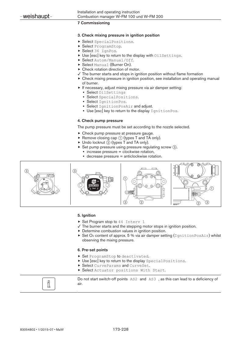
Installation and operating instructionCombustion manager W-FM 100 und W-FM 2007 Commissioning
83054802 1/2015-07 MaW 173-228
3. Check mixing pressure in ignition positionSelect SpecialPositions.Select ProgramStop.Select 36 IgnPos.Use [esc] key to return to the display with OilSettings.Select Autom/Manual/Off.Select Manual (Burner On).Check rotation direction of motor.The burner starts and stops in ignition position without flame formationCheck mixing pressure in ignition position, see installation and operating manualof burner.If necessary, adjust mixing pressure via air damper setting:
Select OilSettingsSelect SpecialPositions.Select IgnitionPos.Select IgnitionPosAir and adjust.Use [esc] key to return to the display IgnitionPos.
4. Check pump pressureThe pump pressure must be set according to the nozzle selected.
Check pump pressure at pressure gauge.Remove closing cap 1 (types T and TA only).Undo locknut 2 (types T and TA only).Set pump pressure using pressure regulating screw 3.
increase pressure = clockwise rotation,decrease pressure = anticlockwise rotation.
+
1
3 3
3 2 2 3
1
5. IgnitionSet Program stop to 44 Interv 1The burner starts and the stepping motor stops in ignition position.Determine combustion values in ignition position.Set O2 content of approx. 5 % via air damper setting (IgnitionPosAir) whilstobserving the mixing pressure.
6. Pre-set pointsSet ProgramStop to deactivated.Use [esc] key to return to the display SpecialPositions.Select CurveParams and CurveSet.Select Actuator positions With Start.
Do not start switch-off points AS2 and AS3 , as this can lead to a deficiency ofair.
Installation and operating instructionCombustion manager W-FM 100 und W-FM 2007 Commissioning
83054802 1/2015-07 MaW 174-228
7. Preset operating point BS1Select BS1 with [ENTER].The burner drives to operating point BS1.Check combustion values and, if necessary, adjust via air damper setting (Air).Exit BS1 using [esc] key and save with [ENTER] key.
8. Preset switch-on point ES2Select ES2.Set excess air (O2 content approx. 7 %) whilst observing flame stability.
For two stage burners onlyTwo stage burners do not have a switch-on point ES3 and no operating point BS3. Operating point BS2 is full load and should be adjusted as full loaf point BS3 (fullload).
9. Pre-set operating point BS2Select BS2.Valve for nozzle 2 opens.Check combustion values and, if necessary, adjust via air damper setting (Air).
10. Pre-set switch-on point ES3Select ES3.Set excess air (O2 content approx. 7 %) whilst observing flame stability.
11. Adjust operating point BS3 (full load)Select BS3.Valve for nozzle 3 opens.Determine oil throughput and if necessary adjust pump pressure.Check combustion valuesDetermine combustion limit and set excess air [ch. 7.9].Use [esc] key to return to the display CurveSet.
The pump pressure must not be altered once this work has been completed.
12. Define switch-off points AS2 and AS3In menu CurveSet select option Without start.Select switch-off point AS2.Set air damper setting in switch-on point ES2 .Select switch-off point AS3.Set air damper setting in switch-on point ES3 .Use [esc] key to return to the display CurveSet.
Installation and operating instructionCombustion manager W-FM 100 und W-FM 2007 Commissioning
83054802 1/2015-07 MaW 175-228
13. Optimise operating points BS1 and BS2Once full load has been adjusted and the pump pressure has been set to its finalvalue, the operating points should be optimised.
In menu CurveSet select option With start.Select BS1.Check combustion values and, if necessary, adjust via air damper setting (Air).Select BS2 and also adjust.
14. Check switch pointsActivate operating points several times and observe switch-over behaviour.If necessary optimise operating behaviour:
Adjust switch-off point in menu Without start whilst increasing the airdamper setting to avoid soot and CO formationAdjust switch-on points in menu With start
15. Check start behaviourSwitch off and restart burner.Check start behaviour and if necessary correct ignition load setting.
If the ignition load setting has been altered:Re-check start behaviour.
16. Set burner to automatic operationExit level using the [esc] key.Select Autom/Manual/Off.Set Automatic.Use [esc] key to return to the display with Param & Display.Select ManualOperation.Select SetLoad.Set highest stage as the target load.Exit level using the [esc] key.If necessary adjust load controller.
17. Data backupExit level using the [esc] key.The display shows Create parameter backup?.Start data backup by pressing [ENTER] key.The display shows Parameters are being updated and the Parameters have been saved.The values have been backed up from the combustion manager to the ABE.Exit level using the [esc] key.

Installation and operating instructionCombustion manager W-FM 100 und W-FM 2007 Commissioning
83054802 1/2015-07 MaW 176-228
7.3 Load controllerThe W-FM 200 is equipped with an internal PID load controller as standard, withthe W-FM 100 the internal load controller is optional.Commissioning must only be carried out by qualified personnel.
7.3.1 Configure load controller
1. Enter passwordSelect Param & Display.Select Access with HE (password for heating engineer).Enter HE password using dial knob and confirm with [ENTER] [ch. 6.2.1].
2. Set operating modeSelect LoadController.Select Configuration.Select LC_OptgMode.Set operating mode for the internal or external load controller using dial knoband confirm with [ENTER] [ch. 6.12.2].Use [esc] key to return to the display LC_OptgMode.
3. Define sensorsFor operating mode with internal load controller and temperature monitor function,the connected sensors must be defined [ch. 3.3.20].
Select Sensor Select.Define connected sensor with the dial knob and confirm with [ENTER][ch. 6.12.3].Use [esc] to return to the display Sensor Select.
To ensure the actual value is entered correctly, the measuring range of the sensorsmust be defined [ch. 6.12.5].
Select menu for the sensor defined and confirm with [ENTER].Sensor: MeasureRangePtNi / var.RangePtNiTemperature sensor: MRange TempSensPressure sensor: MRange PressSens
Set end of measuring range using dial knob and confirm with [ENTER].Use [esc] to return to the menu.
If a sensor is connected, input X61 has to be matched to the sensor [ch. 6.12.4].Select Ext Inp X61 U/I.Set analogue signal from the sensor.Use [esc] to return to the display Ext Inp X61 U/I .
4. Configuring analogue input X62If an analogue setpoint or load signal is present at input X62, the input must bematched to the signal [ch. 6.12.4].
Select Ext Inp X62 U/I.Match input to the analogue signal.Use [esc] to return to the display Ext Inp X62 U/I .
Installation and operating instructionCombustion manager W-FM 100 und W-FM 2007 Commissioning
83054802 1/2015-07 MaW 177-228
5. Limit external setpointIt is possible to define limits for the setpoint for the operating mode with externalsetpoint.With an analogue setpoint signal the limit value relates to the measuring range set[ch. 6.12.6].
Select Ext MinSetpoint or Ext MaxSetpoint .Set the limit value using the dial knob and confirm with [ENTER].Use [esc] to return to the menu.
6. Determine internal setpointTwo setpoints can be set for the operating mode with internal load controller[ch. 6.12.1].
Select LoadController.Select ControlParam.Select SetpointW1 .Set setpoint using the dial knob and confirm with [ENTER].Use [esc] to return to the display ControlParam.
If the second setpoint W2 is required:Repeat procedure for SetpointW2.
7. Temperature sensor functionWith an activated temperature monitor, the switch threshold and switch-on hyster-esis can be set [ch. 6.12.13].
Select LoadController.Select TempLimiter.Select TL_ThreshOff.Set threshold using the dial knob and confirm with [ENTER].Use [esc] to return to the display TL_ThreshOff .Select TL_SD_On.Set switch-on hysteresis using the dial knob and confirm with [ENTER].Use [esc] to return to the display TempLimiter.
Installation and operating instructionCombustion manager W-FM 100 und W-FM 2007 Commissioning
83054802 1/2015-07 MaW 178-228
7.3.2 Adjust load controller
7.3.2.1 Modulating load control
1. Set switch differentialsThe switch differentials determine the on and off switch point [ch. 6.12.11].The on and off switch points are given as a percentage value and relate to the cur-rent setpoint.Set switch-on point (controller ON):
Select ControlParam.Select Sd_ModOn.Set switch differential using the dial knob and confirm with [ENTER].Use [esc] to return to the display Sd_ModOn .
Set switch-off point (controller OFF):Select Sd_ModOFF.Set switch differential using the dial knob and confirm with [ENTER].Use [esc] to return to the display ControlParam.
2. Determine controller parametersThe control parameters can be determined in two ways:
An automatic adaption identifies the controlled system and forms the PIDparameters [ch. 6.12.15].One PID parameter set can be selected from five standard parameter sets[ch. 6.12.8].
Identifying the controlled system via adaption:Select ControlParam.Select SW_FilterTmeCon using the dial knob and confirm with [ENTER].The filter time must be 2 … 4 seconds [ch. 6.12.10].Use [esc] to return to the display ControlParam.Select Adaption .Select AdaptionLoad.Check adaption load and adjust if necessary.If possible, the adaption load should be 100 % [ch. 6.12.15].Use [esc] to return to the display AdaptionLoad.Select StartAdaption using dial knob and confirm with [ENTER].The display shows Start adaption with ENTER.Confirm with [ENTER].Adaption starts, the display shows the individual phases:Temp setbackStabilisation phaseHeatingAdaption ok
Use [esc] to return to the display Adaption.Select PID parameter set immediately:
Select ControlParam.Select ContrlParamList.SelectStandardParam .Select PID parameter set using dial knob and confirm with [ENTER] [ch. 6.12.8].Use [esc] to return to the display StandardParam.

Installation and operating instructionCombustion manager W-FM 100 und W-FM 2007 Commissioning
83054802 1/2015-07 MaW 179-228
3. Edit controller parametersThe PID parameters can be edited individually and the control behaviour can beoptimised [ch. 6.12.8].
Observe control behaviour over a longer period and optimise if necessary.Select P, I or DPart.Change values using the dial knob and confirm with [ENTER] [ch. 6.12.8].Use [esc] to return to the display ContrlParamList.
4. Check fault signal suppressionSelect SW_FilterTmeCon.Check filter time [ch. 6.12.10]:
Temperature sensor (Pt100): 2 … 4 secondspressure sensor (steam plant): 6 … 8 seconds
Use [esc] to return to the display ControlParam.
7.3.2.2 Modulating load control
1. Set switch differentialsThe switch differentials determine the on and off switch points [ch. 6.12.12.1].The on and off switch points are given as a percentage value and relate to the cur-rent setpoint.Set switch-on point (controller ON):
Select ControlParam.Select Sd_Stage1On .Set switch differential using the dial knob and confirm with [ENTER].Use [esc] to return to the display Sd_Stage1On .
Set switch-off point stage 1 (controller OFF):Select Sd_Stage1Off.Set switch differential using the dial knob and confirm with [ENTER].Use [esc] to return to the display Sd_Stage1Off.
Set switch-off point stage 2:Select Sd_Stage2Off.Set switch differential using the dial knob and confirm with [ENTER].Use [esc] to return to the display Sd_Stage2Off.
Set switch-off point stage 3:Select Sd_Stage3Off.Set switch differential using the dial knob and confirm with [ENTER].Use [esc] to return to the display Sd_Stage3Off.
2. Set switch thresholdsThe switch threshold specifies from which control deviation the W-FM activates thenext stage [ch. 6.12.12.2].Set switch threshold stage 2:
Select ThreshStage2On .Set threshold using the dial knob and confirm with [ENTER].Use [esc] to return to the display ThreshStage2On .
Set switch threshold stage 3:Select ThreshStage3On .Set threshold using the dial knob and confirm with [ENTER].Use [esc] to return to the display ControlParam.
Installation and operating instructionCombustion manager W-FM 100 und W-FM 2007 Commissioning
83054802 1/2015-07 MaW 180-228
7.3.2.3 Boiler cold start functionThe boiler cold start function reduces the thermal load of the boiler during burnerstart [ch. 6.12.14].
1. Activate boiler cold start functionSelect ColdStart.Select ColdStartOn.Select activated using the dial knob and confirm with [ENTER].Use [esc] to return to the display ColdStartOn.
2. Define additional sensorOnly if an additional sensor for boiler cold start function is connected (e. g.steam plant):Select AdditionalSens.Define the sensor connected with the dial knob and confirm with [ENTER].Use [esc] to return to the display AdditionalSens.Select Setp AddSensor.Set setpoint using the dial knob and confirm with [ENTER].Use [esc] to return to the display Setp AddSensor.
3. Set switch thresholdsThe switch thresholds relate to the current setpoint or if an additional sensor isconnected to Setp AddSensor.ON threshold:
Select ThresholdOn .Set threshold using the dial knob and confirm with [ENTER].Use [esc] to return to the display ThresholdOn .
OFF threshold:Select ThresholdOff.Set threshold using the dial knob and confirm with [ENTER].Use [esc] to return to the display ThresholdOff.
4. Set StageLoadDetermines the load increase in modulating operation.
Select StageLoad.Set StageLoad using the dial knob and confirm with [ENTER].Use [esc] to return to the display StageLoad.
Installation and operating instructionCombustion manager W-FM 100 und W-FM 2007 Commissioning
83054802 1/2015-07 MaW 181-228
5. Set setpoint stepFor modulating operation:
Select StageSetp_Mod.Set setpoint step using the dial knob and confirm with [ENTER].Use [esc] to return to the display StageSetp_Mod.
For multi-stage operation:Select StageSetp_Stage.Set setpoint step using the dial knob and confirm with [ENTER].Use [esc] to return to the display StageSetp_Stage.
6. Set residence timeFor modulating operation:
Select MaxTmeMod .Set setpoint step using the dial knob and confirm with [ENTER].Use [esc] to return to the display MaxTmeMod.
For multi-stage operation:Select MaxTmeStage.Set setpoint step using the dial knob and confirm with [ENTER].Use [esc] to return to the display MaxTmeStage.
7. Data backupExit level using the [esc] key.The display shows Create parameter backup?.Start data backup by pressing [ENTER] key.The display shows Parameters are being updated and the Parameters have been saved.The values have been backed up from the combustion manager to the ABE.Exit level using the [esc] key.

Installation and operating instructionCombustion manager W-FM 100 und W-FM 2007 Commissioning
83054802 1/2015-07 MaW 182-228
7.4 O2 controllerO2 trim is only possible in modulating operation with W-FM 200 with O2 module.O2 trim is fuel specific and must be set separately for each fuel on dual fuel burn-ers.
Moisture in the O2 sensor.With new sensors or if the sensor has been switched off for extended periods,moisture may form in the sensor and distort the measured value. A longer heat-upprocess through the internal sensor heating displaces this moisture.
Heat up the sensor prior to adjusting the O2 trim.
7.4.1 Set O2 monitorThe O2 limit values are defined in the O2 alarm [ch. 6.10.2]. The operating mode of O2 trim must be set to man deact .
1. Select fuelSelect Param & Display.Select O2 Contr/Alarm.Select GasSettings or OilSettings.Select O2 Alarm and confirm with [ENTER].
2. Set O2 minimum monitorAn O2 MinValue has to be defined as the lower limit in each load point, eitherby:
driving to combustion limit and take over the value determined,direct input, only possible if the O2 minimum value at the combustion limit isalready known.
Only in conjunction with CO controlDetermine the combustion limit using the CO measurement amplifier whilst ob-serving flue values in the reference measuring device.Set O2 minimum monitor to approx. 0.25 … 0.5 percentage points below the com-bustion limit.
Driving to combustion limit and take over the value determined:Select O2 Alarm.Select load point using dial knob and confirm with [ENTER] key.Select PAir Manual and confirm with [ENTER].The display shows the current O2 actual value and the burner drives to the loadpoint.Reduce air rating using the dial knob until the combustion limit is reached(CO content approx. 100 ppm or smoke number approx. 1).Press [ENTER] to accept the O2 actual value.The display shows the value determined as O2 MinValue.Note down O2 MinValue and load point, required in the later stages.Repeat procedure in each load point.Use [esc] to return to the display O2 Alarm.
Direct entry:Select O2 Alarm.Select load point using dial knob and confirm with [ENTER] key.Select O2 MinValue and confirm with [ENTER].Change values using the dial knob and confirm with [ENTER].Exit entry using [esc].Repeat procedure in each load point.Use [esc] to return to the display O2 Alarm.

Installation and operating instructionCombustion manager W-FM 100 und W-FM 2007 Commissioning
83054802 1/2015-07 MaW 183-228
7.4.2 Set O2 trimStandardised values must be defined for O2 trim from a pre-determined load point[ch. 6.10.3].
1. Select fuelSelect Param & Display.Select O2 Contr/Alarm.Select GasSettings or OilSettings.
2. Define O2 setpoints
The setpoint for O2 trim should be approx. 0.5 … 1 %point above the O2MinValue of the O2 monitor. The O2 value in the load points of the compound curve should be approx.2 % points above the setpoint for O2 trim.
Select O2 Control and confirm with [ENTER].Select load point using dial knob and confirm with [ENTER] key.Burner drives to load point.Once the O2 content has stabilised confirm with [ENTER].Turn dial knob to the right.The air influencing actuators drive open on the compound curve, reduce the airquantity and thus the O2 content.The O2 Setpoint should be approx. 0.5 … 1 % points above the 02MinValue at the combustion limit.Confirm standardised value with [ENTER].Exit entry using [esc] and save with [ENTER].In the load point set under LowFireAdaptPtNo and the last load point (fullload) the W-FM carries out an adaption.If the measurement fails in the specified load point, select the next higher loadpoint [ch. 6.10.4].Carry out standardisation in all points, point 2 to full load.
Installation and operating instructionCombustion manager W-FM 100 und W-FM 2007 Commissioning
83054802 1/2015-07 MaW 184-228
7.4.3 Check and optimise O2 trim
1. Bridge load controlIn order to monitor the O2 value via display and operating unit, the load must be in-fluenced manually via an external signal (e. g. 3 pole switch at input X5-03).
It is preferential to monitor O2 trim with software ACS450.
Switch off burner and isolate W-FM from voltage supply.Connect 3 pole switch to input X5-03.Switch on voltage supply.Set load controller operating mode to ExtLC X503, see [ch. 6.12.2].Use [esc] to return to the display LoadController.
2. Set operating modeSelect O2 Contr/Alarm.Select current fuel GasSettings or OilSettings.Select OptgMode.Set conAutoDeac using the dial knob and confirm with [ENTER].Use [esc] to return to the display Param & Display.
3. Set burner to automatic operationSelect ManualOperation.Select Autom/Manual/Off.Set Automatic using dial knob and confirm with [ENTER].Use [esc] to return to the display Autom/Manual/Off.Use [info] to return to OperationalStat.Select NormalOperation.
4. Check O2 trimClose control circuit and drive to full load via 3 pole switch.Check control behaviour whilst monitoring O2 value in the display and operatingunit.The burner drives on the compound curves to full load.Once the O2 sensor has reached operating temperature and the blocking timehas elapsed, the W-FM goes to pre-control [ch. 6.10].Only the air influencing actuators are operating, the fuel actuator remains in itsposition and the O2 actual value approaches the O2 setpoint.If O2 setpoint is not reached via the pre-control, O2 trim reacts and controls theO2 actual value.Change load using the 3 pole switch.O2 trim is suspended and the burner drives to the new load.Pre-control is activated and the compound almost maintains the O2 setpoint.If no changes were made to the load before the blocking time has elapsed, O2
trim is activated and controls the O2 actual value.Drive through the entire load range and monitor the control behaviour.If necessary, optimise O2 trim via the settings in menu ControlParam, see[ch. 6.10.4].

Installation and operating instructionCombustion manager W-FM 100 und W-FM 2007 Commissioning
83054802 1/2015-07 MaW 185-228
Observation ActionO2 actual value fluctuates, at constantload
Change parameter PI see [ch. 6.10.4].In the lower load range:
Increase I LowFire orreduce P LowFire .
In the upper load range:Increase I HighFire ordecrease P HighFire.
O2 sensor reacts very slowly tochanges in the O2 content in the fluegas.
Increase O2 regulating limit [ch. 6.10.4].
O2 trim remains suspended, despite aprolonged period of constant load.
Check status of O2 controller[ch. 6.10.13].Increase parameter LoadCtrlSuspend, see [ch. 6.10.4].
O2 monitor reacts to load change. Check setting of O2 monitor [ch. 7.4.1].Increase parameter O2ModOffset .
5. Set flue gas temperature warning thresholdDrive to full load.Check flue gas temperatureSelect O2 Module.Select Configuration.Select MaxTempFlGas… .Set threshold 20 % above the measured temperature using the dial knob andconfirm with [ENTER].Exit level using the [esc] key.
6. Next fuel (dual fuel burners only)In modulating operation for both fuels:
Repeat setting for second fuel [ch. 7.4.1].

Installation and operating instructionCombustion manager W-FM 100 und W-FM 2007 Commissioning
83054802 1/2015-07 MaW 186-228
7.5 CO controller
Additional informationRefer to the manual of the measuring amplifier LT 3 and combination sensor KS1-Dprior to commissioning. The manual is available to download from the -w- Portal.
The release of level 2 in the measuring amplifier is password protected.Password: 8F3W
7.5.1 Set measurement amplifier LT3The handheld operating unit is required for the settings on the measurement ampli-fier LT3. For detailed information, see instructions Lambda Transmitter LT3 andcombination sensor KS1-D.Setting the language:
Select language in main menu F3.Enter password:
Select Enter Password in main menu F3.Enter password 8F3W and confirm.
Set CO limit value:Select Config LimitValue in main menu F3.Select Config LimitValue 1.Select LV fuel 1 .Select Config fixed value and set 100 ppm .Return to main menu F3
Set standby position of digital output 3 (Out3):Select Digital Outputs in main menu F3.Select Digital Output 3 .Select Standby and set activated .Return to main menu F3
Set trip delay for CO limit value:Select Config LimitValue in main menu F3.Select Config LimitValue 1.Select Trip delay and set 03 s.Return to main display.

Installation and operating instructionCombustion manager W-FM 100 und W-FM 2007 Commissioning
83054802 1/2015-07 MaW 187-228
7.5.2 Set CO controlCommissioning of the O2 controller must be completed for the CO control.
1. Define combustion air sensorsSelect Param & Display.Select O2 Module.Select Configuration.Select SupAirTempSens.Select Pt1000 using dial knob and confirm with [ENTER].Exit display using the [esc] key.
2. Set flue gas temperature warning thresholdSelectMaxTempFlueGas … .Set 850 °C using dial knob and confirm with [ENTER].Use [esc] to return to the display O2 Module.
On dual fuel burners, set both MaxTempFlGasGas and MaxTempFlGasOil.
3. Set blocking timeTo ensure that an increased CO content during burner start does not initiate asafety shutdown, the factor for the blocking time must be set to a minimum of 10[ch. 6.10.5].
Select O2 Contr/Alarm.Select GasSettings or OilSettings.Select NumberTauSuspend.Set a minimum of 10 using dial knob and confirm with [ENTER].Use [esc] to return to the display O2 Module.
On dual fuel burners repeat procedure.
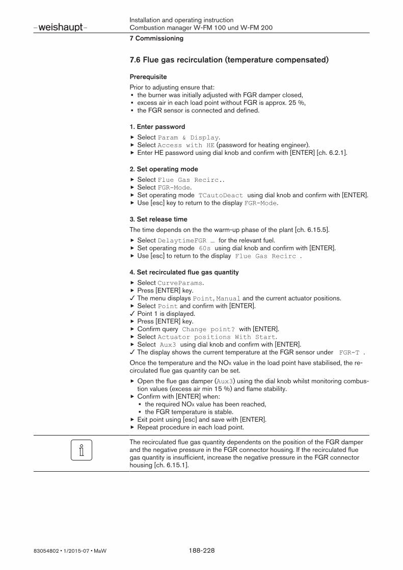
Installation and operating instructionCombustion manager W-FM 100 und W-FM 2007 Commissioning
83054802 1/2015-07 MaW 188-228
7.6 Flue gas recirculation (temperature compensated)
PrerequisitePrior to adjusting ensure that:
the burner was initially adjusted with FGR damper closed,excess air in each load point without FGR is approx. 25 %,the FGR sensor is connected and defined.
1. Enter passwordSelect Param & Display.Select Access with HE (password for heating engineer).Enter HE password using dial knob and confirm with [ENTER] [ch. 6.2.1].
2. Set operating modeSelect Flue Gas Recirc..Select FGRMode.Set operating mode TCautoDeact using dial knob and confirm with [ENTER].Use [esc] key to return to the display FGRMode.
3. Set release timeThe time depends on the the warm-up phase of the plant [ch. 6.15.5].
Select DelaytimeFGR … for the relevant fuel.Set operating mode 60s using dial knob and confirm with [ENTER].Use [esc] to return to the display Flue Gas Recirc .
4. Set recirculated flue gas quantitySelect CurveParams.Press [ENTER] key.The menu displays Point, Manual and the current actuator positions.Select Point and confirm with [ENTER].Point 1 is displayed.Press [ENTER] key.Confirm query Change point? with [ENTER].Select Actuator positions With Start.Select Aux3 using dial knob and confirm with [ENTER].The display shows the current temperature at the FGR sensor under FGRT .
Once the temperature and the NOX value in the load point have stabilised, the re-circulated flue gas quantity can be set.
Open the flue gas damper (Aux3) using the dial knob whilst monitoring combus-tion values (excess air min 15 %) and flame stability.Confirm with [ENTER] when:
the required NOX value has been reached,the FGR temperature is stable.
Exit point using [esc] and save with [ENTER].Repeat procedure in each load point.
The recirculated flue gas quantity dependents on the position of the FGR damperand the negative pressure in the FGR connector housing. If the recirculated fluegas quantity is insufficient, increase the negative pressure in the FGR connectorhousing [ch. 6.15.1].

Installation and operating instructionCombustion manager W-FM 100 und W-FM 2007 Commissioning
83054802 1/2015-07 MaW 189-228
5. Next fuel (dual fuel burners only)In modulating operation for both fuels:
Repeat setting for second fuel.

Installation and operating instructionCombustion manager W-FM 100 und W-FM 2007 Commissioning
83054802 1/2015-07 MaW 190-228
7.7 Set pressure switchesObserve chapter 'Set pressure switches' in the installation and operating manual ofthe burner.
Air pressure switch for variable speed drive and O2 trimOn burners with variable speed drive and O2 trim the air pressure switch is set dif-ferently to the standard method.O2 trim regulates the O2 content in the flue gas via the combustion air quantity. Thisfacilitates positions below partial load for the air influencing actuators. To determinethe lowest differential pressure, the burner must drive to the combustion limit inpoint 2. On dual fuel burners carry out the setting with fuel Gas.
Call up function O2 Alarm, see [ch. 6.10.2].Select menu O2 Alarm and confirm with [ENTER].Select load point 2 using dial knob and confirm with [ENTER] key.Select parameter PAir Manual and confirm with [ENTER].The display shows the current O2 actual value and the burner drives to the loadpoint.Rotate setting cam on air pressure switch to the right, until the W-FM triggers alockout.Turn back setting cam by approx. 1 mbar.Exit level using the [esc] key.Reset burner using the [ENTER] key.
7.8 Concluding workObserve chapter Concluding work in the installation and operating manual of theburner.

Installation and operating instructionCombustion manager W-FM 100 und W-FM 2007 Commissioning
83054802 1/2015-07 MaW 191-228
7.9 Check combustion
Determine excess airSlowly close air damper(s) in the relevant operating point, until the combustionlimit is reached (CO content approx. 100 ppm or smoke number approx. 1).Measure and document O2 content.Read air number (λ).
Increase air number to ensure sufficient excess air:by 0.15 … 0.2 (equates to 15 … 20 % excess air),by more than 0.2 for more difficult conditions, such as:
dirty combustion air,fluctuating intake temperature,fluctuating chimney draught.
Exampleλ + 0.15 = λ*
Set air number (λ*), do not exceed CO content of 50 ppm.Measure and document O2 content.
Check flue gas temperatureCheck flue gas temperature.Ensure that the flue gas temperature complies with the data provided by theboiler manufacturer.If necessary adjust flue gas temperature, e g.:
Increase burner rating in partial load to avoid condensation in the flue gasducts, except on condensing units.Reduce burner rating in full load to improve efficiency.Adjust heat exchanger to the data provided by the manufacturer.
Determine flue gas lossesDrive to full load.Measure combustion air temperature (tL) near the air damper(s).Measure oxygen content (O2) and flue gas temperature (tA) at the same time atone point.Determine flue gas losses using the following formula:
qA = (tA - tL ) ( A2
21- O2) + B
qA Flue gas losses [%]tA Flue gas temperature [°C]tL Combustion air temperature [°C]O2 Volumetric content of oxygen in dry flue gas [%]
Fuel factors Natural Gas Liquid PetroleumGas
Fuel oil
A2 0.66 0.63 0.68B 0.009 0.008 0.007

Installation and operating instructionCombustion manager W-FM 100 und W-FM 2007 Commissioning
83054802 1/2015-07 MaW 192-228
7.10 Calculate gas throughputFormula symbol Explanation Example valuesVB Operating volume in m3/h
Volume measured at gas meter at current pressure andtemperature (gas throughput).
-
VN Standard volume in m3/hVolume gained by gas at 1013 mbar and 0 C.
-
f Conversion factor -QN Heat rating in kW 6000 kWη Boiler efficiency (e. g. 92 % ≙ 0.92) 0.92Hi Calorific value in kWh/m3 (at 0 °C and 1013 mbar) 10.35 kW/m3 (Natural Gas
E)tGas Gas temperature at gas meter in °C 10 °CPGas Pressure at gas meter in mbar 250 mbarPBaro Barometric air pressure in mbar, see table 500 m ≙ 955 mbarVG Gas throughput determined at gas meter 18.2 m³TM Time measured during gas throughput (VG) 120 seconds
Calculate normal volumeCalculate the normal volume (VN) using the following formula.
VN = QN
η HiVN = 6000 kW
0.92 10.35 kW/m3= 630.1 m³/h
Calculate conversion factorDetermine gas temperature (tGas) and pressure (PGas) at gas meter.Determine barometric air pressure (PBaro) from table.
Heightabovesea level[m]
0 100 200 300 400 500 600 700 800 900 1000 1100 1200 1300
PBaro [mbar]
1013 1001 990 978 966 955 943 932 921 910 899 888 877 866
Calculate conversion factor (f) using the following formula.
f= PBaro + PGas
1013273
273 + tGasf= 955+ 250
1013273
273 + 10= 1.148
Calculate operating volume (gas throughput) required
VB = VN
fVB= 630.1 m³/h
0.933=549.1 m³/h
Determine current operating volume (gas throughput)Measure gas throughput (VG) at gas meter, measuring time (TM) should be a min-imum of 60 seconds.Calculate operating volume (VB) using the following formula.
VB = 3600 VG
TMVB= 3600 18.2 m³
120 s=546.0 m³/h

Installation and operating instructionCombustion manager W-FM 100 und W-FM 2007 Commissioning
83054802 1/2015-07 MaW 193-228
7.11 Ratings apportionmentThe load points are automatically assigned relative to the capacity. Incorrect loaddistribution can cause operating problems during the load control.
Assign rating in % for load point to the following formula.Enter the calculated capacity for load point in Load.
Load [%] = Throughput load pointThroughput full load
100

Installation and operating instructionCombustion manager W-FM 100 und W-FM 2008 Servicing
83054802 1/2015-07 MaW 194-228
8 Servicing
8.1 Notes on servicing
Notes on servicing
DANGER
Risk of explosion due to leaking gasImproper service work can lead to escaping gas and explosion.
Close fuel shut off devices prior to starting work.Care should be taken when dismantling and assembling gas carrying compon-ents.Tightly close the screws on the test points ensuring the tests points are sealed.
DANGER
Risk of electric shockWorking on the device when voltage is applied can lead to electric shock.
Isolate the device from the power supply prior to starting any work.Safeguard against accidental re-start.
WARNING
Danger of getting burned on hot componentsHot components can lead to burns.
Allow components to cool.
Servicing must only be carried out by qualified personnel. The combustion plantshould be serviced annually. Depending on site conditions more frequent checksmay be required.Components, which show increased wear and tear or whose design lifespan is orwill be exceeded prior to the next service should be replaced as a precaution[ch. 8.2].
Weishaupt recommends a service contract is entered into to ensure regular in-spections.
The following components must only be replaced and must not be repaired:combustion managerflame sensoractuator (stepping motor)gas valveoil solenoid valve,nozzle shut off (closing needle),pressure regulatorpressure switch.
Prior to every servicingInform the operator about the extent of service work to be carried out.Switch off mains switch of installation and safeguard against accidental reactiva-tion.Close fuel shut off devices.

Installation and operating instructionCombustion manager W-FM 100 und W-FM 2008 Servicing
83054802 1/2015-07 MaW 195-228
Following servicingCheck tightness of oil and gas carrying components.Check function of:
adjustable mixing head,ignition,flame monitoring,gas carrying components (gas connection pressure and setting pressure),oil pump (pump pressure and suction resistance),pressure switchsafety interlock circuit.
Check combustion values, if necessary re-adjust the burner.Enter combustion values and settings in the commissioning record and/or testsheet.
8.2 Service planFor detailed information see installation and operating manual of burner.

Installation and operating instructionCombustion manager W-FM 100 und W-FM 2009 Troubleshooting
83054802 1/2015-07 MaW 196-228
9 Troubleshooting
9.1 Procedures for fault conditionsCheck prerequisites for operation:
Voltage supply availableHeating switch is set to On.Temperature regulator or pressure regulator on heat exchanger has been setcorrectly.Boiler or heating circuit control is functioning and set correctly.
The combustion manager recognises irregularities of the burner and displays theseon the display and operating unit.The following conditions can occur:
FaultLockout
Resetting
OperationalStat Status/Reset
The display and operating unit alternately shows the shutdown behaviour and thefault diagnosed as a plain text display.
CAUTION
Damage resulting from incorrect servicingThe combustion plant could be damaged.
Do not carry out more than 2 lockout resets successively.Faults must be rectified by qualified personnel.
If the ABE displays a fault:Exit display using the [esc] key.Reset burner using the [ENTER] key.
If the [esc] key has been pressed twice, reset can only be carried out via the menu.Select OperationalStat.Select Status/Reset.Current lockout is displayed.Exit display using the [esc] key.Reset burner using the [ENTER] key.
Via reset key on input X4-01:4:Press reset key.The burner has been reset.
Exchanging the unitIf the combustion manager or the ABE are replaced:
Select and check fault history and lockout history and include a copy when re-turning the unit for exchange.
Installation and operating instructionCombustion manager W-FM 100 und W-FM 2009 Troubleshooting
83054802 1/2015-07 MaW 197-228
9.1.1 Deactivating an alarmOperationalStat Alarm act/deact
Parameter Alarm act/deact deactivates or activates the alarm outputX3-01:2.A reset or a burner start automatically resets the deactivation and the alarm outputis ready for use again.

Installation and operating instructionCombustion manager W-FM 100 und W-FM 2009 Troubleshooting
83054802 1/2015-07 MaW 198-228
9.2 FaultIf a fault occurs, the combustion manager initiates a controlled shutdown.The display and operating unit alternately shows the shutdown behaviour and thefault diagnosed as a plain text display.
Example
Safetyshutdown
Safety loopis open
The burner restarts automatically as soon as the fault condition has been rectified.
Fault history
OperationalStat FaultHistory
Parameter FaultHistory alternately shows the last 21 faults as plain text ordiagnostic display [ch. 9.4].
Select History using dial knob and confirm with [ENTER].Browse history with the dial knob.The display changes every 5 seconds between plain text and diagnostic display.The [ENTER] key can be used to manually change the display.Exit History using [esc] key.
Normal operationStatus/ResetFault historyLockout history Safety loop
is open 1 Class:00 OilCode:21 Phase:24Diag:00 Load: 100Start No. 18
21 Class:00 OilCode:26 Phase:60Diag:00 Lst:42.5Start No. 1232
5 sec
The diagnostic display provides information about:Fault number (1 … 21)Fault class (Class:)Current fuel when fault occurred (Oil or Gas)Fault code (Code:)Operating phase when fault occurred (Phase:)Diagnostic code (Diag:)Load setting or stage when fault occurred (Load:)Number of burner starts (Start No.)

Installation and operating instructionCombustion manager W-FM 100 und W-FM 2009 Troubleshooting
83054802 1/2015-07 MaW 199-228
9.3 LockoutIf a lockout condition occurs, the combustion manager initiates a fault shutdownand burner lockout.The display and operating unit alternately shows the shutdown behaviour and thefault diagnosed as a plain text display.Once the fault has been rectified, the combustion manager has to be reset for re-start.
Example
LockoutAir pressure isoff
Lockout history
OperationalStat LockoutHistory
Parameter LockoutHistory alternately displays the last 9 faults as plain text ordiagnostic display [ch. 9.4].
Select History using dial knob and confirm with [ENTER].Browse history with the dial knob.The display changes every 5 seconds between plain text and diagnostic display.The [ENTER] key can be used to manually change the display.Exit History using [esc] key.
Normal operationStatus/ResetFault historyLockout history
Air pressure isoff
1 01.04.15 13:22C:28 D:00 P:62Start No. 22Load:79.6 Gas
9 06.11.15 08:15C:31 D:00 P:81Start No. 4711Load:25.0 Gas
5 sec
The diagnostic display provides information about:Fault number (1 … 21)Date when fault occurred (dd.mm.yy)Time when fault occurred (hh.mm)Fault code (C:)Diagnostic code (D:)Operating phase when fault occurred (P:)Number of burner starts (Start No.)Load setting or stage when fault occurred (Load:)Current fuel when fault occurred (Oil or Gas)

Installation and operating instructionCombustion manager W-FM 100 und W-FM 2009 Troubleshooting
83054802 1/2015-07 MaW 200-228
9.4 Rectifying faultsFaultcodes
Diagnosticcode
Cause Rectification
01 01 ROM error Internal fault(1
02 01 … 07 RAM error Internal fault(1
03 01 … 60 Error during internal data comparison Internal fault(1^^
04 – Synchronisation error Internal fault(1^^
05 01 … 03 Error flame signal amplifier test Check electrical connectionReplace flame sensor.
^^
06 01 … 04 Error internal hardware test Internal fault(1^^
10 01 … 1B Error on input or output The diagnostic code indicates which input oroutput is affected.
01 Load controller external on / off Check neutral conductor to W-FM.Check electrical connectionCheck if a capacitive load is connected.A fault could be triggered if the internalrelay switches off and the capacitive loaddelays the voltage drop by 10 ms.
Internal fault(1
* Depending on the operating phase an im-permissible voltage signal is present at thecorresponding output. This could betriggered by reverse voltage caused by anoperating signal (e. g. during a lamp test).
02 Fan contactor contact03 Fuel selection Oil04 Fuel selection Gas05 Reset06 Maximum oil pressure switch07 Minimum oil pressure switch08 Valve proving gas pressure switch09 Anti syphon valve / safety valve Oil SV return
signal X6-03*0A Fuel valve Oil V1 return signal
X8-02 / X8-03*0B Fuel valve Oil V2 return signal X7-01*0C Fuel valve Oil V3 return signal X7-02*0D Safety valve Gas SV return signal X9-01:1*0E Fuel valve Gas V1 return signal X9-01:4*0F Fuel valve Gas V2 return signal X9-01:3*10 Ignition gas valve PV return signal X9-01:2*11 Safety circuit, burner flange limit switch12 Internal safety relay return signal13 Low gas pressure switch14 High gas pressure switch15 Ignition return signal16 Air pressure switch17 Start release Oil18 Heavy oil immediate start19 External load controller open1A External load controller closed1B Start release Gas
^^
11 01 Contact return signal network short circuit Internal fault(1
€€
(1 If occurring sporadically: Optimise EMC measures. If occurring continuously replace defective component.
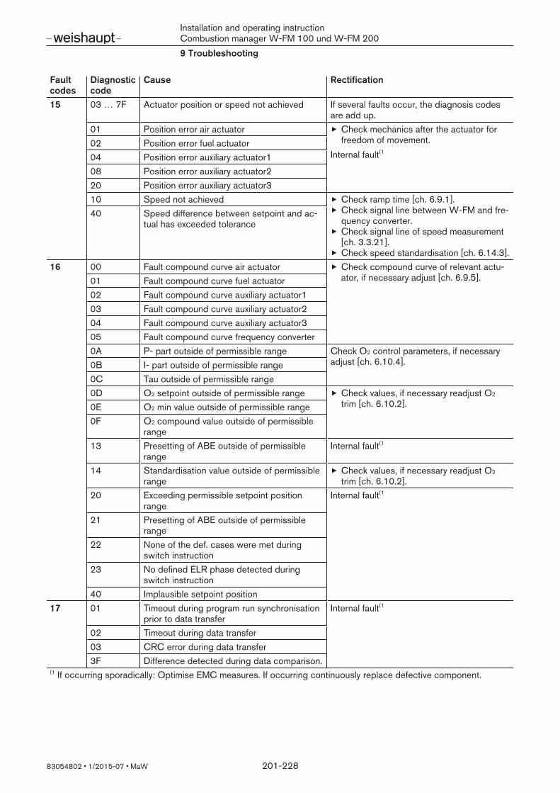
Installation and operating instructionCombustion manager W-FM 100 und W-FM 2009 Troubleshooting
83054802 1/2015-07 MaW 201-228
Faultcodes
Diagnosticcode
Cause Rectification^^
15 03 … 7F Actuator position or speed not achieved If several faults occur, the diagnosis codesare add up.
01 Position error air actuator Check mechanics after the actuator forfreedom of movement.
Internal fault(102 Position error fuel actuator04 Position error auxiliary actuator108 Position error auxiliary actuator220 Position error auxiliary actuator310 Speed not achieved Check ramp time [ch. 6.9.1].
Check signal line between W-FM and fre-quency converter.Check signal line of speed measurement[ch. 3.3.21].Check speed standardisation [ch. 6.14.3].
40 Speed difference between setpoint and ac-tual has exceeded tolerance
^^
16 00 Fault compound curve air actuator Check compound curve of relevant actu-ator, if necessary adjust [ch. 6.9.5].01 Fault compound curve fuel actuator
02 Fault compound curve auxiliary actuator103 Fault compound curve auxiliary actuator204 Fault compound curve auxiliary actuator305 Fault compound curve frequency converter0A P- part outside of permissible range Check O2 control parameters, if necessary
adjust [ch. 6.10.4].0B I- part outside of permissible range0C Tau outside of permissible range0D O2 setpoint outside of permissible range Check values, if necessary readjust O2
trim [ch. 6.10.2].0E O2 min value outside of permissible range0F O2 compound value outside of permissible
range13 Presetting of ABE outside of permissible
rangeInternal fault(1
14 Standardisation value outside of permissiblerange
Check values, if necessary readjust O2
trim [ch. 6.10.2].20 Exceeding permissible setpoint position
rangeInternal fault(1
21 Presetting of ABE outside of permissiblerange
22 None of the def. cases were met duringswitch instruction
23 No defined ELR phase detected duringswitch instruction
40 Implausible setpoint position^^
17 01 Timeout during program run synchronisationprior to data transfer
Internal fault(1
02 Timeout during data transfer03 CRC error during data transfer3F Difference detected during data comparison.
€€
(1 If occurring sporadically: Optimise EMC measures. If occurring continuously replace defective component.

Installation and operating instructionCombustion manager W-FM 100 und W-FM 2009 Troubleshooting
83054802 1/2015-07 MaW 202-228
Faultcodes
Diagnosticcode
Cause Rectification^^
18 – Invalid value in a compound curve Check compound curves.Valid load range: 0 … 100 %Valid position range: 0 … 90°Valid speed range: 0 … 100 %
During initial commissioning:Correct value.
After previously correct operation:Replace W-FM.
^^
19 01 … 2F Actuator error during comparison betweenpotentiometer channel A and B
If several faults occur, the diagnosis codesare add up.
01 Air actuator fault Set allowed Pot.diff to 15, see[ch. 6.13.3].Check CAN Bus connection [ch. 5].
Internal fault(1
02 Fuel actuator fault04 Auxiliary actuator1 fault08 Auxiliary actuator2 fault20 Auxiliary actuator3 fault
^^
1A 1 Curve gradient between two load points toogreat.Maximum permissible gradient at 0.1 % loadchange:
3.6° (with 30 s ramp time)1.8° (with 60 s ramp time)0.9° (with 120 s ramp time)
Change load assignment in the loadpoints to fall below the maximum permiss-ible gradient [ch. 6.9.5].
^^
1B – The burner shuts down during the setting ofthe compound curves due to lack of heat de-mand.
Set compound curves in Manual op-erating mode [ch. 6.7].Prevents shutdown by the load controller. Shutdown only occurs if the temperaturemonitor responds. The current load pointbeing adjusted can still be saved.
^^
1C 01 … 3F Ignition position for the relevant actuator ismissing.
If several faults occur, the diagnosis codesare add up.
01 Air actuator ignition position missing Set ignition position [ch. 6.9.4].02 Fuel actuator ignition position missing04 Auxiliary actuator1 ignition position missing08 Auxiliary actuator2 ignition position missing10 Frequency converter ignition position miss-
ing20 Auxiliary actuator3 ignition position missing
^^
1D 01 … 3F Run time fault actuators / frequency con-verter
If several faults occur, the diagnosis codesare add up.
01 Air actuator run time fault Check mechanics after the actuator forfreedom of movement.Check actuator voltage supply.Check actuator ramp time [ch. 6.9.1].Ramp time should not be less slowest ac-tuator
02 Fuel actuator run time fault04 Auxiliary actuator1 run time fault08 Auxiliary actuator2 run time fault10 Frequency converter run time fault20 Auxiliary actuator3 run time fault
€€
(1 If occurring sporadically: Optimise EMC measures. If occurring continuously replace defective component.

Installation and operating instructionCombustion manager W-FM 100 und W-FM 2009 Troubleshooting
83054802 1/2015-07 MaW 203-228
Faultcodes
Diagnosticcode
Cause Rectification^^
1E 01 … 3F At least one actuator has not reached thespecified special position.
If several faults occur, the diagnosis codesare add up.
01 Air actuator has not reached the special po-sition
Check mechanics after the actuator forfreedom of movement.Check actuator voltage supply.02 Fuel actuator has not reached the special
position04 Auxiliary actuator1 has not reached the spe-
cial position08 Auxiliary actuator2 has not reached the spe-
cial position10 Frequency converter has not reached the
special position20 Auxiliary actuator3 has not reached the spe-
cial position40 Speed has not reached the special position Check ramp time [ch. 6.9.1].
Check signal line between W-FM and fre-quency converter.Check signal line of speed measurement[ch. 3.3.21].Check speed standardisation [ch. 6.14.3].
^^
1F 01 Internal test of frequency converter modulefailed
Internal fault(1
02 Rotational direction of fan incorrect Check rotation direction of motor.Check transmitter disc for speedmeasurement [ch. 3.3.21].Check rotational direction of frequencyconverter.
03 Impulse fault during speed measurement Check transmitter disc and proximityswitch for speed measurement[ch. 3.3.21].
04 Speed is not stable during speed standard-isation
Check motor.Check transmitter disc and proximityswitch for speed measurement[ch. 3.3.21].
05 Air actuator has not reached pre-purge posi-tion
Check mechanics after the actuator forfreedom of movement.Check actuator voltage supply.
06 Internal speed test failed Internal fault(1
07 Safety circuit not closed during speedstandardisation
Check safety circuit^^
21 – Safety circuit not closed Check safety circuit^^
22 – Threshold of temperature monitor exceeded Check temperature of plant.Check setting of temperature limiter[ch. 6.12.13].
^^
23 01 … 03 Extraneous light during start-up Find and eliminate extraneous light sourceCheck flame sensorFuel valves leaking, check.
^^
24 01 … 03 Extraneous light during shutdown^^
25 01 … 03 No flame at the end of the safety time Check ignition.Check burner settingCheck flame sensorCheck fuel valves.
€€
(1 If occurring sporadically: Optimise EMC measures. If occurring continuously replace defective component.

Installation and operating instructionCombustion manager W-FM 100 und W-FM 2009 Troubleshooting
83054802 1/2015-07 MaW 204-228
Faultcodes
Diagnosticcode
Cause Rectification^^
26 01 … 03 Flame failure during operation Check burner settingCheck fuel supplyCheck flame signal [ch. 6.4.7].
^^
27 – Impermissible ON signal from air pressureswitch
Check air pressure switch [ch. 3.3.4].Check pressure switch release [ch. 3.4.4].
28 – Impermissible OFF signal from air pressureswitch
^^
29 – Impermissible ON signal from fan contactorcontact
Check electrical connection and fan con-tactor contact [ch. 3.3.5].
Supply for contactor contact X3-02:12A – Impermissible OFF signal from fan contactorcontact
^^
2B – Impermissible ON signal from FGR air pres-sure switch
^^
2C – Impermissible OFF signal from FGR air pres-sure switch
^^
2D – Impermissible ON signal at input start re-lease Gas
^^
2E – Impermissible OFF signal at input start re-lease Gas
^^
2F – Low gas pressure switch has reacted Check gas connection pressure.Check gas pressure switch30 – High gas pressure switch has reacted
^^
31 – Valve proving gas pressure switch has re-acted, contact open, V1 leaking or V2 doesnot open.
Check gas pressure switchCheck double gas valve
32 – Valve proving gas pressure switch hasdropped out, contact closed, V2 or ignitiongas valve leaking or V1 does not open.
^^
33 – Unexpected oil pressure, min. oil pressureswitch has triggered, contact closed
34 – Min. oil pressure switch has not reacted,contact open
Check pump pressure.Check oil supplyCheck min. oil pressure switch.35 – Max. oil pressure switch has triggered, con-
tact closed^^
36 – No signal at input start release Oil [ch. 3.3.9]^^
37 – No signal at input heavy oil immediate start[ch. 3.3.10]
^^
38 – Low gas programme activated Check gas connection pressure.^^
39 – Internal safety time error^^
3A – No burner identification is saved in theW-FM.
Transfer data from the ABE [ch. 6.16.1].^^
3B – No HE password defined^^
40 – Internal safety relay fault^^
41 – Internal ignition contact setting fault Check electrical connection at output.€€
(1 If occurring sporadically: Optimise EMC measures. If occurring continuously replace defective component.

Installation and operating instructionCombustion manager W-FM 100 und W-FM 2009 Troubleshooting
83054802 1/2015-07 MaW 205-228
Faultcodes
Diagnosticcode
Cause Rectification^^
42 01 … FF Internal fuel valve relay contact setting fault If several faults occur, the diagnosis codesare add up.
01 Anti syphon valve / safety valve Oil SVX6-03*
Check electrical connection at output.Depending on the operating phase an imper-missible voltage signal is present at the cor-responding output. This could be triggeredby reverse voltage caused by an operatingsignal (e. g. during a lamp test).
02 Fuel valve Oil V1 X8-02 / X8-0304 Fuel valve Oil V2 X7-0108 Fuel valve Oil V3 X7-0210 External solenoid valve Gas / safety valve
Gas SV X9-01:120 Fuel valve Gas V1 X9-01:440 Fuel valve Gas V2 X9-01:380 Ignition gas valve PV X9-01:2
^^
43 01 No fuel or both selected via input X4-01 Check electrical connection [ch. 6.4.2].02 Fuel supply without compound curves Set fuel.03 Variable "Supply" not defined Transfer data from the ABE [ch. 6.16.1].04 Variable "Fuel" not defined Check fuel selection [ch. 6.4.2].05 Undefined operating mode with load control-
lerCheck operating mode [ch. 6.12.2].
06 Pre-purge time Gas too short Internal fault(1
07 Pre-purge time Oil too short08 Safety time 1 Gas too long09 Safety time 1 Oil too long0A Time ignition Off greater than safety time 1
Gas0B Time ignition Off greater than safety time 1
Oil0C Safety time 2 Gas too long0D Safety time 2 Oil too long
^^
44 01 … 04 Deactivated input connected. Activate input or connect nothing.Some inputs can only be activated in theOEM level.
01 Load controller input X6202 Air pressure switch input X3-0203 Fan contactor contact input X4-01:304 Low gas pressure switch input X9-03:405 High gas pressure switch input X9-03:306 Min. oil pressure switch input X5-0107 Max. oil pressure switch input X5-0208 Start release Oil input X6-01:109 Heavy oil immediate start input X6-01:30A Start release Gas input X7-03:20B Safety temperature monitor for high temper-
ature input X6-01:3^^
45 – Safety shutdown during safety temperaturelimiter test
€€
(1 If occurring sporadically: Optimise EMC measures. If occurring continuously replace defective component.
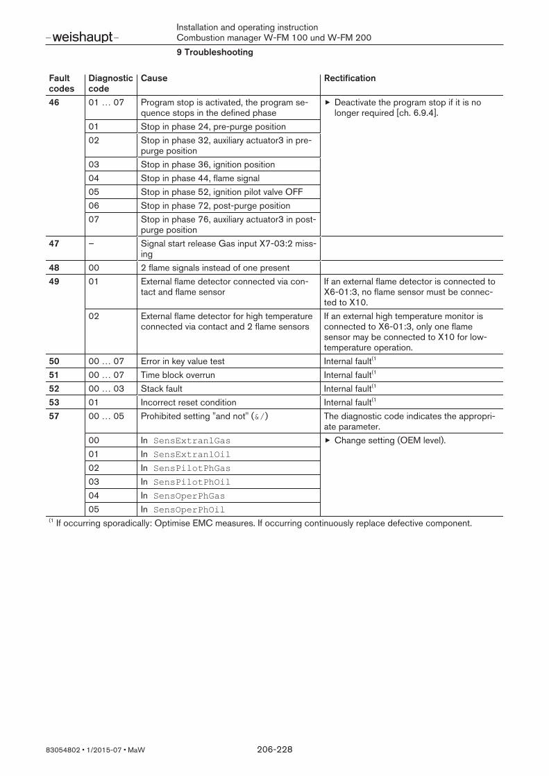
Installation and operating instructionCombustion manager W-FM 100 und W-FM 2009 Troubleshooting
83054802 1/2015-07 MaW 206-228
Faultcodes
Diagnosticcode
Cause Rectification^^
46 01 … 07 Program stop is activated, the program se-quence stops in the defined phase
Deactivate the program stop if it is nolonger required [ch. 6.9.4].
01 Stop in phase 24, pre-purge position02 Stop in phase 32, auxiliary actuator3 in pre-
purge position03 Stop in phase 36, ignition position04 Stop in phase 44, flame signal05 Stop in phase 52, ignition pilot valve OFF06 Stop in phase 72, post-purge position07 Stop in phase 76, auxiliary actuator3 in post-
purge position^^
47 – Signal start release Gas input X7-03:2 miss-ing
^^
48 00 2 flame signals instead of one present^^
49 01 External flame detector connected via con-tact and flame sensor
If an external flame detector is connected toX6-01:3, no flame sensor must be connec-ted to X10.
02 External flame detector for high temperatureconnected via contact and 2 flame sensors
If an external high temperature monitor isconnected to X6-01:3, only one flamesensor may be connected to X10 for low-temperature operation.
^^
50 00 … 07 Error in key value test Internal fault(1^^
51 00 … 07 Time block overrun Internal fault(1^^
52 00 … 03 Stack fault Internal fault(1^^
53 01 Incorrect reset condition Internal fault(1^^
57 00 … 05 Prohibited setting "and not" (&/) The diagnostic code indicates the appropri-ate parameter.
00 In SensExtranlGas Change setting (OEM level).01 In SensExtranlOil02 In SensPilotPhGas03 In SensPilotPhOil04 In SensOperPhGas05 In SensOperPhOil
€€
(1 If occurring sporadically: Optimise EMC measures. If occurring continuously replace defective component.
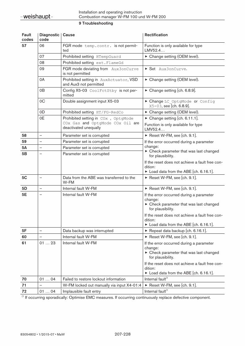
Installation and operating instructionCombustion manager W-FM 100 und W-FM 2009 Troubleshooting
83054802 1/2015-07 MaW 207-228
Faultcodes
Diagnosticcode
Cause Rectification^^
57 06 FGR mode temp.contr. is not permit-ted
Function is only available for typeLMV52.4…
07 Prohibited setting HTempGuard Change setting (OEM level).08 Prohibited setting ext.FlameGd09 FGR mode deviating from Aux3onCurve
is not permittedSet Aux3onCurve.
0A Prohibited setting in AuxActuator, VSDand Aux3 not permitted
Change setting (OEM level).
0B Config X5-03 CoolFctStby is not per-mitted
Change setting [ch. 6.8.9].
0C Double assignment input X5-03 Change LC_OptgMode or ConfigX503, see [ch. 6.8.9].
0D Prohibited setting HT/FGRedCo Change setting (OEM level).0E Prohibited setting in COx , OptgMode
COx Gas and OptgMode COx Oil aredeactivated unequally
Change setting [ch. 6.11.1].Function is only available for typeLMV52.4…
^^
58 – Parameter set is corrupted Reset W-FM, see [ch. 9.1].If the error occurred during a parameterchange:
Check parameter that was last changedfor plausibility.
If the reset does not achieve a fault free con-dition:
Load data from the ABE [ch. 6.16.1].
59 – Parameter set is corrupted5A – Parameter set is corrupted5B – Parameter set is corrupted
^^
5C – Data from the ABE was transferred to theW-FM
Reset W-FM, see [ch. 9.1].^^
5D – Internal fault W-FM Reset W-FM, see [ch. 9.1].If the error occurred during a parameterchange:
Check parameter that was last changedfor plausibility.
If the reset does not achieve a fault free con-dition:
Load data from the ABE [ch. 6.16.1].
5E – Internal fault W-FM
^^
5F – Data backup was interrupted Repeat data backup [ch. 6.16.1].^^
60 – Internal fault W-FM Reset W-FM, see [ch. 9.1].If the error occurred during a parameterchange:
Check parameter that was last changedfor plausibility.
If the reset does not achieve a fault free con-dition:
Load data from the ABE [ch. 6.16.1].
61 01 … 23 Internal fault W-FM
^^
70 01 … 04 Failed to restore lockout information Internal fault(1^^
71 – W-FM locked out manually via input X4-01:4 Reset W-FM, see [ch. 9.1].^^
72 01 … 04 Implausible fault entry Internal fault(1
€€
(1 If occurring sporadically: Optimise EMC measures. If occurring continuously replace defective component.

Installation and operating instructionCombustion manager W-FM 100 und W-FM 2009 Troubleshooting
83054802 1/2015-07 MaW 208-228
Faultcodes
Diagnosticcode
Cause Rectification^^
80 01 … 03 Prohibited condition auxiliary actuator3 Check CAN Bus connection and Bustermination [ch. 5].
Internal fault(181 01 … 03 Prohibited condition air actuator82 01 … 03 Prohibited condition fuel actuator Gas83 01 … 03 Prohibited condition fuel actuator Oil84 01 … 03 Prohibited condition auxiliary actuator185 01 … 03 Prohibited condition auxiliary actuator2^^
86 01 … 03 Prohibited condition internal load controller Internal fault(1^^
87 01 … 03 Prohibited condition ABE Check CAN Bus connection and Bustermination [ch. 5].
Internal fault(1^^
88 01 Plausibility fault actuators Internal fault(1
02 Plausibility fault load controller03 Plausibility fault ABE04 Plausibility fault frequency converter module05 Plausibility fault O2 module
^^
90 – ROM-CRC error auxiliary actuator3 Check CAN Bus connection and Bustermination [ch. 5].
Internal fault(191 – ROM-CRC error air actuator92 – ROM-CRC error fuel actuator Gas93 – ROM-CRC error fuel actuator Oil94 – ROM-CRC error auxiliary actuator195 – ROM-CRC error auxiliary actuator296 – ROM-CRC error auxiliary actuator2 Internal fault(1
97 – ROM-CRC error ABE Check CAN Bus connection and Bustermination [ch. 5].
Internal fault(1
98 – At least two actuators with the same ad-dress on the CAN-Bus
Check address [ch. 6.13.1].
99 – CAN-Bus connection error Check CAN Bus connection and Bustermination [ch. 5].
Internal fault(19A CAN-Bus connection error, error often oc-
curs when a bus user is connected or dis-connected
9B Queue overflow CAN-Bus€€
(1 If occurring sporadically: Optimise EMC measures. If occurring continuously replace defective component.

Installation and operating instructionCombustion manager W-FM 100 und W-FM 2009 Troubleshooting
83054802 1/2015-07 MaW 209-228
Faultcodes
Diagnosticcode
Cause Rectification^^
A0 01 … 1F Auxiliary actuator3 has signalled a fault Check CAN Bus connection and Bustermination [ch. 5].
Internal fault(101 CRC error during ROM test02 CRC error during RAM test04 Error in key value test05 Time block overrun07 Synchronisation or CRC error08 Cycle counter error09 Error during stack test0C Temperature in the actuator too high Check housing temperature (max. 60°C), if
necessary supply with cooling air.0D Rotational direction of actuator incorrect Check mechanics after the actuator for
freedom of movement.Check rotation direction, change if re-quired (OEM level).
0E Ramp time for path insufficient Check actuator ramp time [ch. 6.9.1].Ramp time should not be less slowest ac-tuatorReduce path between special positions.
10 Timeout during analogue to digital conver-sion
Internal fault(1
11 Error during test analogue to digital con-verter
12 Error during analogue to digital conversion13 Actuator position outside of permissible
range (0 … 90°)Check actuator position, if necessary turnback mechanically.
15 CAN-Bus connection error Check CAN Bus connection [ch. 5].16 CRC error of parameter page17 Page was open too long Reset W-FM, see [ch. 9.1].
If the error occurred during a parameterchange:
Check parameter that was last changedfor plausibility.
If the reset does not achieve a fault free con-dition:
Load data from the ABE [ch. 6.16.1].If none of the actions listed leads to a faultfree condition:
Replace W-FM.
18 Page has been corrupted19 Invalid access to parameters1B Error when copying a parameter page
1E Invalid position range in drive command Check SpecialPositions.Valid position range: 0 … 90°
1F Internal plausibility fault Optimise EMC measures.^^
A1 See A0 Air actuator has signalled a fault See A0^^
A2 See A0 Fuel actuator Gas has signalled a fault See A0^^
A3 See A0 Fuel actuator Oil has signalled a fault See A0^^
A4 See A0 Auxiliary actuator1 has signalled a fault See A0^^
A5 See A0 Auxiliary actuator2 has signalled a fault See A0€€
(1 If occurring sporadically: Optimise EMC measures. If occurring continuously replace defective component.

Installation and operating instructionCombustion manager W-FM 100 und W-FM 2009 Troubleshooting
83054802 1/2015-07 MaW 210-228
Faultcodes
Diagnosticcode
Cause Rectification^^
A6 10 … 32 Internal load controller has signalled a fault Internal fault(1
10 No actual value gradient12 Invalid proportional part (Xp) Check O2 control parameters, if necessary
adjust [ch. 6.10.4].Internal fault(1
13 Invalid integral part (Tn)14 Invalid delay time (Tu)15 Invalid differential part (Tv)16 Timeout during observation phase of auto-
matic adaptionInternal fault(1
17 Boiler cold start function is activated18 Timeout during automatic adaption22 Setpoint exceeds limit value30 … 32 Internal memory fault
^^
A6 33 CRC error during data transfer Reset W-FM, see [ch. 9.1].Repeat data backup [ch. 6.16.1].
^^
A6 34 … 3B Internal load controller fault Internal fault(1^^
A6 40 Page was open too long Reset W-FM, see [ch. 9.1].If the error occurred during a parameterchange:
Check parameter that was last changedfor plausibility.
If the reset does not achieve a fault free con-dition:
Load data from the ABE [ch. 6.16.1].If none of the actions listed leads to a faultfree condition:
Replace W-FM.^^
A6 41 … 43 Internal load controller fault Internal fault(1^^
A6 41 … 46 Error in the data set from the internal loadcontroller
44 Page was set to ABORT Reset W-FM, see [ch. 9.1].If the error occurred during a parameterchange:
Check parameter that was last changedfor plausibility.
If the reset does not achieve a fault free con-dition:
Load data from the ABE [ch. 6.16.1].If none of the actions listed leads to a faultfree condition:
Replace W-FM.
45 Page was set to RESTO46 Page has invalid status
^^
A6 4A … 4E Internal load controller connection errorCAN-Bus
Internal fault(1
€€
(1 If occurring sporadically: Optimise EMC measures. If occurring continuously replace defective component.

Installation and operating instructionCombustion manager W-FM 100 und W-FM 2009 Troubleshooting
83054802 1/2015-07 MaW 211-228
Faultcodes
Diagnosticcode
Cause Rectification^^
A6 50 … 5A Load controller input error The diagnostic code indicates which input isaffected.
50 Short circuit at input X60:1/4 Check electrical connection and sensor.51 Break at input X60:1/452 Break at input X60:2/453 Short circuit at input X60:3/454 Break at input X60:3/455 Short circuit at input X60:3/456 Break at input X60:3/457 Excess voltage at input X6158 Break or short circuit at input X6159 Excess voltage at input X625A Break or short circuit at input X62
^^
A6 5B The output value is not available for outputX63 in the current configuration.
Change setting [ch. 6.12.7].^^
A6 5C FGR sensor is not available in the currentconfiguration.
Change setting [ch. 6.15.3].^^
A6 60 … 6F Internal load controller fault Internal fault(1^^
A6 70 … 77 Load controller input signals fluctuate toomuch
The diagnostic code indicates which input isaffected [ch. 3.3.20].
70 Signal fluctuation input X60:1/4 Check electrical connectionCheck signal (ripple voltage).71 Signal fluctuation input X60:2/4
72 Signal fluctuation input X60:3/473 Signal fluctuation PWM74 Signal fluctuation U-input X61:275 Signal fluctuation I-input X61:376 Signal fluctuation U-input X62:2/477 Signal fluctuation I-input X62:3/4
^^
A6 78 … 7F Load controller input signals too great or in-correct polarity.
The diagnostic code indicates which input isaffected [ch. 3.3.20].
78 Excess voltage or incorrect polarity inputX60:1/4
Check electrical connectionCheck voltage or current.
79 Excess voltage or incorrect polarity inputX60:2/4
7A Excess voltage or incorrect polarity inputX60:3/4
7B Excess voltage or incorrect polarity PWM7C Excess voltage or incorrect polarity input
X617D Current flow is too high or incorrect polarity
input X617E Excess voltage or incorrect polarity input
X627F Current flow is too high or incorrect polarity
input X62^^
A6 80 … A6 Internal load controller fault Internal fault(1
€€
(1 If occurring sporadically: Optimise EMC measures. If occurring continuously replace defective component.

Installation and operating instructionCombustion manager W-FM 100 und W-FM 2009 Troubleshooting
83054802 1/2015-07 MaW 212-228
Faultcodes
Diagnosticcode
Cause Rectification^^
A6 A7 Incorrect or no additional sensor for boilercold start function defined.
Change setting [ch. 6.12.14].^^
A6 B0 … FF Internal load controller fault Internal fault(1^^
A7 01 … 08 Internal fault ABE Check CAN Bus connection and Bustermination [ch. 5].
Internal fault(1
09 Burner is locked out via OFF function ofABE.
Reset W-FM, see [ch. 9.1].
0A Internal fault ABE0B Service message through burner starts Carry out service, reset start counter
[ch. 6.4.4].0C Save parameters failed0D OilSettings was selected in the menu,
the fuel selection is set to Gas.Select fuel Gas [ch. 6.4.2].
0E GasSettings was selected in the menu,the fuel selection is set to Oil.
Select fuel Oil [ch. 6.4.2].
15 … 1A Internal fault ABE Internal fault(1
1B Error during data backup Reset W-FM, see [ch. 9.1].Repeat data backup [ch. 6.16.1].
1C … 28 Internal fault ABE30 Bus communication error Check connection and settings
[ch. 6.6.2].38 Interface mode could not be completed
[ch. 6.6.1]40 Configuration error via software (PC tool)88 … 8A Internal fault ABE
€€
(1 If occurring sporadically: Optimise EMC measures. If occurring continuously replace defective component.

Installation and operating instructionCombustion manager W-FM 100 und W-FM 2009 Troubleshooting
83054802 1/2015-07 MaW 213-228
Faultcodes
Diagnosticcode
Cause Rectification^^
A9 01 … 1F Internal frequency converter module has sig-nalled a fault
01 … 09 Internal frequency converter module fault Internal fault(1
0A Speed or fuel meter not plausible, interfer-ence on the line
Check line installation.Use screened line.
Internal fault(1
0C Signal from frequency converter at alarm in-put X73:3 [ch. 3.4.11]
Read fault code from frequency converter
0D Frequency converter module can not com-pensate the speed difference
Check current signal for frequencyconverter [ch. 6.14.5].The current signal of the W-FM must bematched to the frequency converter.Carry out speed standardisation[ch. 7.2.1.1].
The burner requires re-commissioning aftereach standardisation.
0E Error internal speed calculation Internal fault(1
15 CAN-Bus connection error Check CAN Bus connection and Bustermination [ch. 5].
16 CRC error of parameter page Reset W-FM, see [ch. 9.1].If the error occurred during a parameterchange:
Check parameter that was last changedfor plausibility.
If the reset does not achieve a fault free con-dition:
Load data from the ABE [ch. 6.16.1].If none of the actions listed leads to a faultfree condition:
Replace W-FM.
17 Page was open too long18 Page has been corrupted19 Invalid access to parameters1B Error when copying a parameter page
1E Invalid position range in drive command Check SpecialPositions.Valid position range: 0 … 100°
1F Internal plausibility fault Internal fault(1
€€
(1 If occurring sporadically: Optimise EMC measures. If occurring continuously replace defective component.

Installation and operating instructionCombustion manager W-FM 100 und W-FM 2009 Troubleshooting
83054802 1/2015-07 MaW 214-228
Faultcodes
Diagnosticcode
Cause Rectification^^
AB 01 … 3F O2 module has signalled a fault01 … 0A Internal O2 module fault Internal fault(1
10 Nernst voltage of O2 sensor outside of per-missible range
Check electrical connection [ch. 3.3.25].
12 Voltage thermocouple of O2 sensor outsideof permissible range
13 Voltage temperature compensation of O2
sensor outside of permissible range15 Temperature combustion air sensor outside
of permissible range (-20 … +800°C)Check electrical connection and sensor[ch. 6.10.9].Check temperature.16 Temperature flue gas temperature sensor
outside of permissible range(-20 … +800°C)
17 … 1F Internal fault O2 module in test phase Internal fault(1
20 Sensor temperature of O2 sensor too low Check voltage supply and unit fusing ofinternal O2 module.Check voltage supply sensor heating(Q4/Q5) [ch. 3.3.25].
21 Sensor temperature of O2 sensor too high Check sensor temperature [ch. 6.10.20].22 Errors during calculation test Internal fault(1
23 Internal resistance of O2 sensor less than5 Ω or greater than 150 Ω
Check electrical connection [ch. 3.3.25].Replace O2 sensor [ch. 6.10.22].
24 Reaction time of O2 sensor greater than5 seconds
Check installation position of O2 sensor[ch. 4.1].Clean O2 sensor.Replace O2 sensor (sensor ageing).If necessary increase O2 control limit.
25 Error during sensor test [ch. 6.10.22]. O2
value fluctuates, flow too low.
30 CAN-Bus connection error Check CAN Bus connection and Bustermination [ch. 5].
Internal fault(1
31 CRC error of parameter page Reset W-FM, see [ch. 9.1].If the error occurred during a parameterchange:
Check parameter that was last changedfor plausibility.
If the reset does not achieve a fault free con-dition:
Load data from the ABE [ch. 6.16.1].If none of the actions listed leads to a faultfree condition:
Replace W-FM.
32 Page was open too long33 Page has been corrupted34 Invalid access to parameters38 Error when copying a parameter page3E Invalid external default
3F Internal plausibility fault Internal fault(1^^
B0 01, 02 Fault during output test Internal fault(1^^
B1 01 Error in short circuit testing of inputs to out-puts
Internal fault(1
€€
(1 If occurring sporadically: Optimise EMC measures. If occurring continuously replace defective component.

Installation and operating instructionCombustion manager W-FM 100 und W-FM 2009 Troubleshooting
83054802 1/2015-07 MaW 215-228
Faultcodes
Diagnosticcode
Cause Rectification^^
B5 01 O2 min. value not maintained [ch. 6.10.2] Check setting of compound curve[ch. 6.10.3].Increase O2 Offset [ch. 6.10.4].increase distance O2 min. value to O2 set-point value [ch. 6.10].
02 At least one O2 min. value is missing Check O2 min. values [ch. 6.10.2].03 At least one O2 setpoint is missing Check O2 setpoints [ch. 6.10.3].04 Adaption error in the load point defined un-
der LowFireAdaptPtNo or in full loadRepeat standardisation in both load points[ch. 6.10.3].Increase LowFireAdaptPtNo, see[ch. 6.10.4].
05 No valid O2 value for at least 3 seconds Check connection of O2 module and O2
sensor.06 Air oxygen content not achieved in pre-
purge (20.9 % ± 2 %)Fully open air influencing actuators in pre-purge [ch. 6.9.4].Increase pre-purge time [ch. 6.8.1].Replace O2 sensor (sensor ageing).
07 O2 max. value not maintained [ch. 6.10.2] Check installation position and connec-tion of O2 sensor [ch. 4.1].
08 O2 min. value or O2 max. value is missing[ch. 6.10.2]
Check O2 max. value.Check O2 min. value at each load point
Flue gas reaction time (Tau) is missing in theload point defined under LowFireAdaptPtNo or in full load [ch. 6.10.4]
Repeat standardisation in the relevantload point [ch. 6.10.3].
09 Test time for O2 monitor missing Change setting (OEM level).0A Internal W-FM fault in conjunction with O2
trimInternal fault(1
^^
B6 01 CO signal outside of the permissible range[ch. 6.11]
Check CO resistance circuit boardconnection [ch. 3.3.24].
02 Prohibited setting Time COx Alarm Check setting [ch. 6.11.2].03 Flue gas reaction time (Tau) is missing in the
load point defined under LowFireAdaptPtNo or in full load [ch. 6.10.4]
Repeat standardisation in the relevantload point [ch. 6.10.3].
04 CO limit value in operation exceeded Check combustion.Check CO limit value of measurementtransducer LT3 [ch. 7.5.1].Increase O2ModOffset, see [ch. 6.10.4].Increase NumberTauSuspend, see[ch. 6.10.5].
05 CO limit value in pre-purge exceeded Fully open air influencing actuators in pre-purge [ch. 6.9.4].Increase pre-purge time [ch. 6.8.1].
^^
B7 00 … 3F Error message from O2 module, no valid COsignal
Check CO resistance circuit boardconnection [ch. 3.3.24].
41 Connection between W-FM and O2 moduleinterrupted
Check CAN Bus connection [ch. 5].
42 Connection error CAN Bus between W-FMand O2 module
Check CAN Bus connection [ch. 5].
^^
BA 01 O2 module has aborted test of O2 sensor Internal fault(1^^
BB 00 Service interval for O2 sensor expired Clean or replace O2 sensor.Reset service interval [ch. 6.10.8].
€€
(1 If occurring sporadically: Optimise EMC measures. If occurring continuously replace defective component.
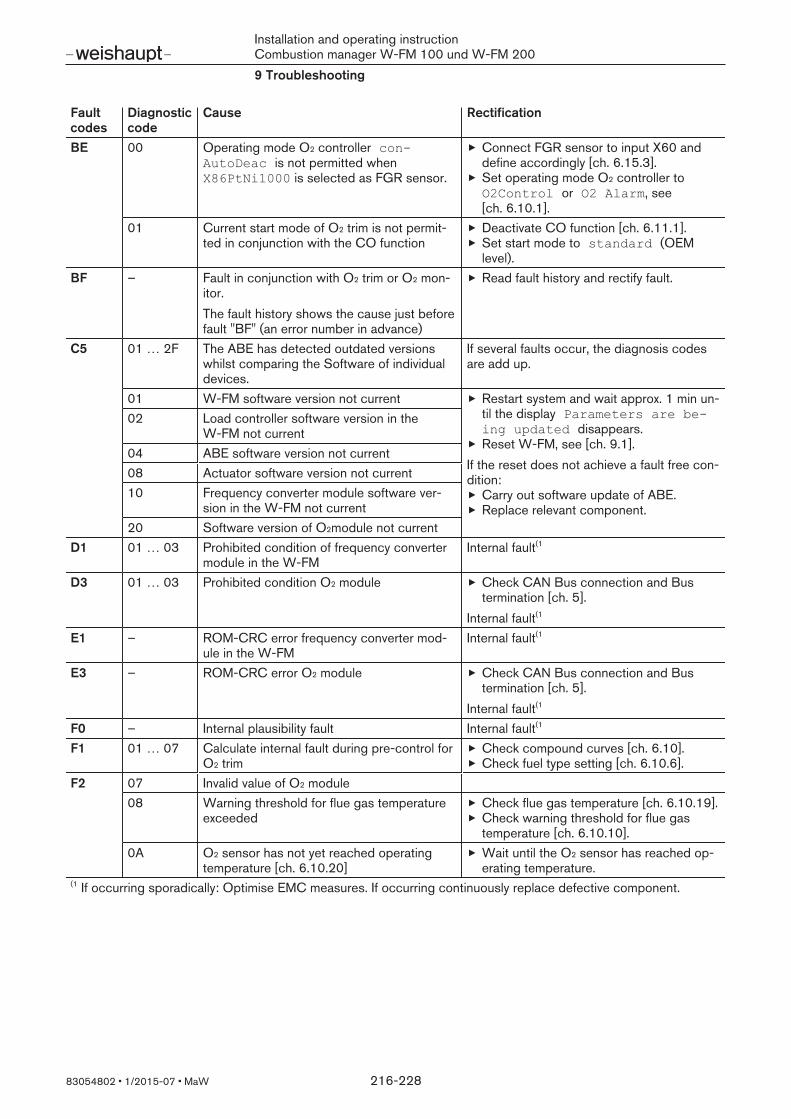
Installation and operating instructionCombustion manager W-FM 100 und W-FM 2009 Troubleshooting
83054802 1/2015-07 MaW 216-228
Faultcodes
Diagnosticcode
Cause Rectification^^
BE 00 Operating mode O2 controller conAutoDeac is not permitted whenX86PtNi1000 is selected as FGR sensor.
Connect FGR sensor to input X60 anddefine accordingly [ch. 6.15.3].Set operating mode O2 controller toO2Control or O2 Alarm, see[ch. 6.10.1].
01 Current start mode of O2 trim is not permit-ted in conjunction with the CO function
Deactivate CO function [ch. 6.11.1].Set start mode to standard (OEMlevel).
^^
BF – Fault in conjunction with O2 trim or O2 mon-itor.The fault history shows the cause just beforefault "BF" (an error number in advance)
Read fault history and rectify fault.
^^
C5 01 … 2F The ABE has detected outdated versionswhilst comparing the Software of individualdevices.
If several faults occur, the diagnosis codesare add up.
01 W-FM software version not current Restart system and wait approx. 1 min un-til the display Parameters are being updated disappears.Reset W-FM, see [ch. 9.1].
If the reset does not achieve a fault free con-dition:
Carry out software update of ABE.Replace relevant component.
02 Load controller software version in theW-FM not current
04 ABE software version not current08 Actuator software version not current10 Frequency converter module software ver-
sion in the W-FM not current20 Software version of O2module not current
^^
D1 01 … 03 Prohibited condition of frequency convertermodule in the W-FM
Internal fault(1
^^
D3 01 … 03 Prohibited condition O2 module Check CAN Bus connection and Bustermination [ch. 5].
Internal fault(1^^
E1 – ROM-CRC error frequency converter mod-ule in the W-FM
Internal fault(1
^^
E3 – ROM-CRC error O2 module Check CAN Bus connection and Bustermination [ch. 5].
Internal fault(1^^
F0 – Internal plausibility fault Internal fault(1^^
F1 01 … 07 Calculate internal fault during pre-control forO2 trim
Check compound curves [ch. 6.10].Check fuel type setting [ch. 6.10.6].
^^
F2 07 Invalid value of O2 module08 Warning threshold for flue gas temperature
exceededCheck flue gas temperature [ch. 6.10.19].Check warning threshold for flue gastemperature [ch. 6.10.10].
0A O2 sensor has not yet reached operatingtemperature [ch. 6.10.20]
Wait until the O2 sensor has reached op-erating temperature.
€€
(1 If occurring sporadically: Optimise EMC measures. If occurring continuously replace defective component.

Installation and operating instructionCombustion manager W-FM 100 und W-FM 2009 Troubleshooting
83054802 1/2015-07 MaW 217-228
Faultcodes
Diagnosticcode
Cause Rectification^^
F3 01 O2 trim PI parameter missing Check PI parameter [ch. 6.10.4].02 No values defined for O2 control variable
limitDefine O2 control variable limit[ch. 6.10.4].
03 O2 control variable limit has been activated Check O2 content in the flue gas and O2
sensor [ch. 6.10.16].Check O2 control variable limit[ch. 6.10.4].
Check O2 trim setting [ch. 6.10.2].04 Curve parameters for O2 trim incomplete Check curve points for O2 trim
[ch. 6.10.2].O2 compound valuesO2 setpointsO2 min. valuesStandardisation values
05 Internal fault W-FM06 Supply air temperature present is not valid
when setting O2 trimCheck supply air temperature sensor.Check combustion air temperature duringcommissioning [ch. 6.10.5].
07 Blocking time for the O2 sensor QGO 21 in-sufficient
Increase factor NumberTauSuspend,see [ch. 6.10.5].
08 O2 value above 135 during controller initial-isation in phase 60
Check O2 sensor (malfunction, secondaryair).Increase factor NumberTauSuspend,see [ch. 6.10.5].
^^
F4 01 Connection error CAN Bus between W-FMand O2 module
Check CAN Bus connection [ch. 5].
15 Temperature combustion air sensor outsideof permissible range (-20 … +800°C)
Check electrical connection and sensor[ch. 6.10.9].Check temperature.16 Temperature flue gas temperature sensor
outside of permissible range(-20 … +800°C)
^^
F5 – Load controller return signal fault Check CAN Bus connection [ch. 5].Internal fault(1
F6 01 FGR function was automatically deactivatedThe fault history shows the cause just beforefault "F6" (an error number in advance)
Read fault history and rectify fault.
02 Operating mode FGR TCautoDeact isnot permitted when X86PtNi1000 is se-lected as FGR sensor.
Connect FGR sensor to input X60 anddefine accordingly [ch. 6.15.3].Set FGR mode to temp.contr., see[ch. 6.15.2].
€€
(1 If occurring sporadically: Optimise EMC measures. If occurring continuously replace defective component.

Installation and operating instructionCombustion manager W-FM 100 und W-FM 20010 Technical documentation
83054802 1/2015-07 MaW 218-228
10 Technical documentation
10.1 Frequency converter
Detailed information see Frequency converter CD.
The construction and arrangement of diagnostic LEDs is dependent on the size ofthe frequency converter.
10.1.1 Frequency converter Nord size I ... III
1 2
3
ON
12
1 2 3
1 Interfaces2 DIP switches3 Diagnostic LED's
InterfaceThe interface is used to access the frequency converter via a PC. The Software required can be found on the Frequency Converter CD. A connection cable RJ12 to SUB-D9 is required for the connection (Order No. 743361). A readily available USB interfaces converter USB to RS232 is also requiredfor the connection to the USB port.
DIP switchesThe analogue inputs AIN1 and AIN2 are configured via setting of the DIP switches.Factory setting (4 … 20 mA):
Switch 1: ONSwitch 2: ON
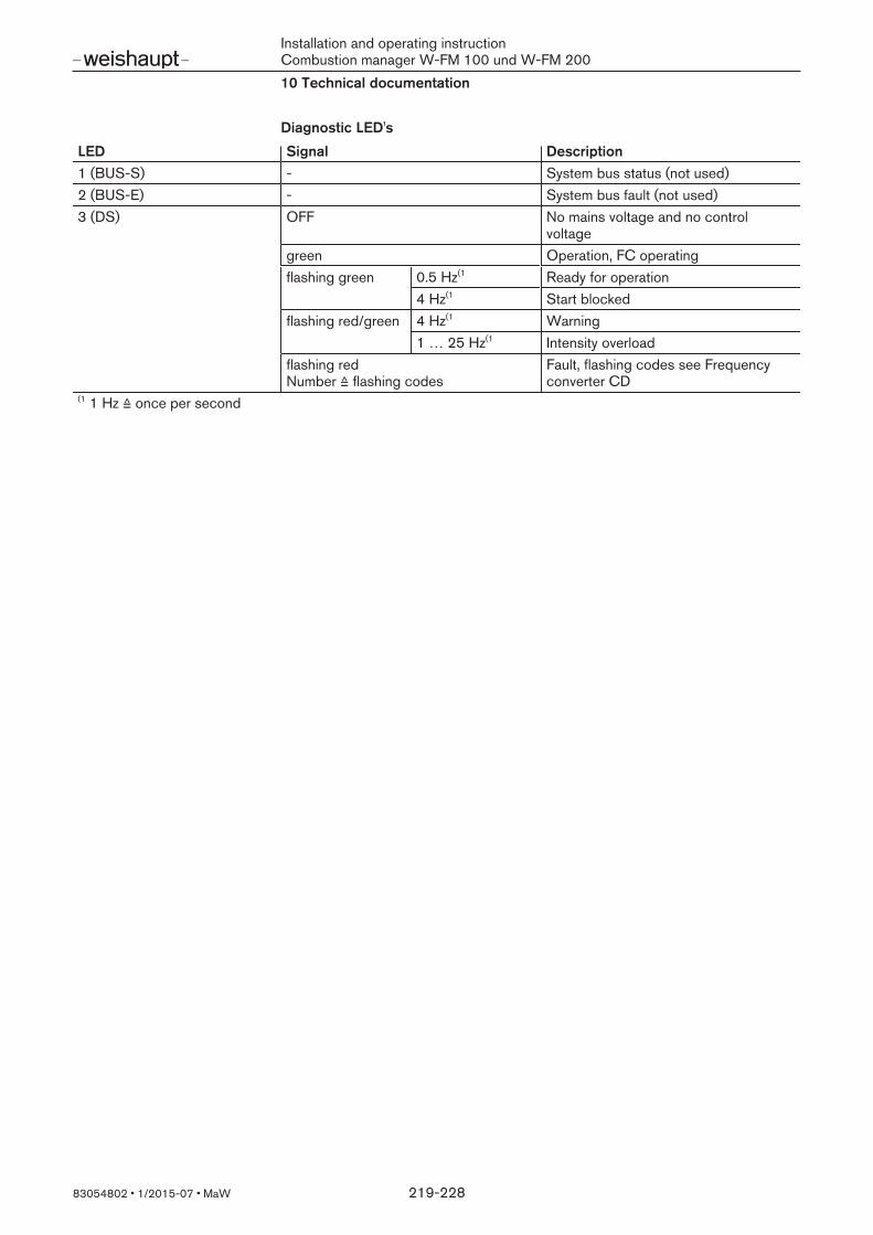
Installation and operating instructionCombustion manager W-FM 100 und W-FM 20010 Technical documentation
83054802 1/2015-07 MaW 219-228
Diagnostic LED's
LED Signal Description1 (BUS-S) - System bus status (not used)2 (BUS-E) - System bus fault (not used)3 (DS) OFF No mains voltage and no control
voltagegreen Operation, FC operatingflashing green 0.5 Hz(1 Ready for operation
4 Hz(1 Start blockedflashing red/green 4 Hz(1 Warning
1 … 25 Hz(1 Intensity overloadflashing redNumber ≙ flashing codes
Fault, flashing codes see Frequencyconverter CD
€€
(1 1 Hz ≙ once per second

Installation and operating instructionCombustion manager W-FM 100 und W-FM 20010 Technical documentation
83054802 1/2015-07 MaW 220-228
10.1.2 Frequency converter Nord size IV
2 318
7 654
9 0 B A
31 2
1 Interfaces2 Diagnostic LED's3 Status LED's
InterfaceThe interface is used to access the frequency converter via a PC. The Software required can be found on the Frequency Converter CD. A connection cable RJ12 to SUB-D9 is required for the connection (Order No. 743361). A readily available USB interfaces converter USB to RS232 is also requiredfor the connection to the USB port.
Diagnostic LED's
LED Signal Description1 (DOUT1 ) yellow Alarm from frequency converter (digital
output 1)2 (DOUT2) yellow Signal at digital output 23 (BRAKE) yellow Mechanical brake4 (TEMP) yellow Excess temperature at motor5 (DIN4) yellow Signal at digital input 46 (DIN3) yellow Signal at digital input 37 (DIN2) yellow Signal at digital input 38 (DIN1) yellow Frequency converter start release (di-
gital input 1)9 (BUS-S) OFF No Bus communication (system bus)
green Bus warningflashing green Bus communication
0 (BUS-E) OFF System bus is operating correctlyflashing red Monitoring faultred No system bus

Installation and operating instructionCombustion manager W-FM 100 und W-FM 20010 Technical documentation
83054802 1/2015-07 MaW 221-228
Status LED's
LED Signal DescriptionA (AS-i) - Status AS interface (not used)B (DS) OFF No mains voltage and no control
voltagegreen Operation, FC operatinggreen ON +red flashing
Frequency converter not ready for oper-ation,control voltage applied but no mainsvoltage
flashing green 0.5 Hz(1 Ready for operation4 Hz(1 Start blocked
flashing red/green 4 Hz(1 Warning1… 25 Hz(1 Intensity overload
flashing redNumber ≙ flashing codes
Fault, flashing codes see Frequencyconverter CD
€€
(1 1 Hz ≙ once per second
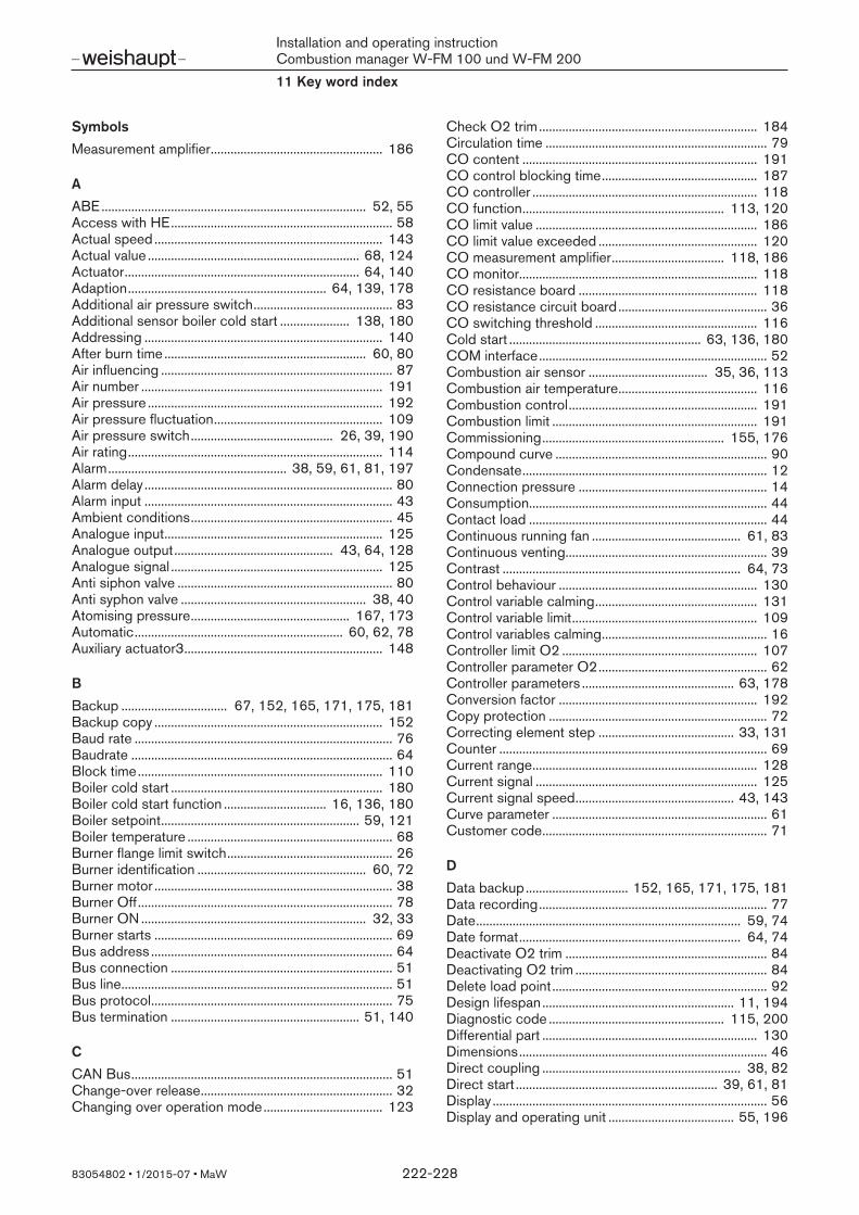
Installation and operating instructionCombustion manager W-FM 100 und W-FM 20011 Key word index
83054802 1/2015-07 MaW 222-228
11 Key word index
SymbolsMeasurement amplifier.................................................... 186
AABE................................................................................ 52, 55Access with HE................................................................... 58Actual speed ..................................................................... 143Actual value ................................................................ 68, 124Actuator....................................................................... 64, 140Adaption............................................................ 64, 139, 178Additional air pressure switch.......................................... 83Additional sensor boiler cold start ..................... 138, 180Addressing ........................................................................ 140After burn time ............................................................. 60, 80Air influencing ...................................................................... 87Air number ......................................................................... 191Air pressure ....................................................................... 192Air pressure fluctuation................................................... 109Air pressure switch........................................... 26, 39, 190Air rating............................................................................. 114Alarm...................................................... 38, 59, 61, 81, 197Alarm delay ........................................................................... 80Alarm input ........................................................................... 43Ambient conditions............................................................. 45Analogue input.................................................................. 125Analogue output................................................ 43, 64, 128Analogue signal ................................................................ 125Anti siphon valve ................................................................. 80Anti syphon valve ........................................................ 38, 40Atomising pressure................................................ 167, 173Automatic............................................................... 60, 62, 78Auxiliary actuator3............................................................ 148
BBackup ................................ 67, 152, 165, 171, 175, 181Backup copy ..................................................................... 152Baud rate .............................................................................. 76Baudrate ............................................................................... 64Block time.......................................................................... 110Boiler cold start ................................................................ 180Boiler cold start function ............................... 16, 136, 180Boiler setpoint............................................................ 59, 121Boiler temperature .............................................................. 68Burner flange limit switch.................................................. 26Burner identification ................................................... 60, 72Burner motor ........................................................................ 38Burner Off............................................................................. 78Burner ON .................................................................... 32, 33Burner starts ........................................................................ 69Bus address ......................................................................... 64Bus connection ................................................................... 51Bus line.................................................................................. 51Bus protocol......................................................................... 75Bus termination ......................................................... 51, 140
CCAN Bus............................................................................... 51Change-over release.......................................................... 32Changing over operation mode.................................... 123
Check O2 trim.................................................................. 184Circulation time ................................................................... 79CO content ....................................................................... 191CO control blocking time............................................... 187CO controller .................................................................... 118CO function............................................................. 113, 120CO limit value ................................................................... 186CO limit value exceeded ................................................ 120CO measurement amplifier.................................. 118, 186CO monitor........................................................................ 118CO resistance board ...................................................... 118CO resistance circuit board............................................. 36CO switching threshold ................................................. 116Cold start .......................................................... 63, 136, 180COM interface..................................................................... 52Combustion air sensor .................................... 35, 36, 113Combustion air temperature.......................................... 116Combustion control......................................................... 191Combustion limit .............................................................. 191Commissioning....................................................... 155, 176Compound curve ................................................................ 90Condensate.......................................................................... 12Connection pressure ......................................................... 14Consumption........................................................................ 44Contact load ........................................................................ 44Continuous running fan ............................................. 61, 83Continuous venting............................................................. 39Contrast ........................................................................ 64, 73Control behaviour ............................................................ 130Control variable calming................................................. 131Control variable limit........................................................ 109Control variables calming.................................................. 16Controller limit O2 ........................................................... 107Controller parameter O2................................................... 62Controller parameters .............................................. 63, 178Conversion factor ............................................................ 192Copy protection .................................................................. 72Correcting element step ......................................... 33, 131Counter ................................................................................. 69Current range.................................................................... 128Current signal ................................................................... 125Current signal speed................................................ 43, 143Curve parameter ................................................................. 61Customer code.................................................................... 71
DData backup............................... 152, 165, 171, 175, 181Data recording..................................................................... 77Date................................................................................ 59, 74Date format................................................................... 64, 74Deactivate O2 trim ............................................................. 84Deactivating O2 trim .......................................................... 84Delete load point................................................................. 92Design lifespan.......................................................... 11, 194Diagnostic code ..................................................... 115, 200Differential part ................................................................. 130Dimensions........................................................................... 46Direct coupling ............................................................ 38, 82Direct start ............................................................. 39, 61, 81Display ................................................................................... 56Display and operating unit ...................................... 55, 196
Installation and operating instructionCombustion manager W-FM 100 und W-FM 20011 Key word index
83054802 1/2015-07 MaW 223-228
Display contrast........................................................... 64, 73Disposal ................................................................................ 12Double gas valve................................................................. 42
EeBus............................................................................... 64, 76eBus address....................................................................... 76Edit load point...................................................................... 91Efficiency........................................................... 60, 111, 114Electrical connection.......................................................... 50Emergency-Off .................................................................... 26Enable contact..................................................................... 43Excess air........................................................................... 191Exchanging the unit ......................................................... 196External setpoint........................................................ 63, 127Extraneous light .................................................... 30, 61, 85
FFactory identification ............................ 61, 64, 65, 66, 71Factory setting ..................................................................... 59Fan.......................................................................................... 79Fan contactor contact........................................................ 27Fan motor.............................................................................. 38Fault code.......................................................................... 200Fault history ................................................................ 59, 198Fault signal ........................................................................ 131FC setpoint........................................................................ 143FGR maximum position .................................................. 151FGR minimum position ................................................... 151FGR operating mode ...................................................... 148FGR release ...................................................................... 150FGR temperature ................................................... 149, 151FGR temperature sensor ........................................ 35, 149Flame failure test ....................................................... 67, 154Flame sensor........................................................................ 30Flame signal ................................................... 30, 31, 61, 71Flame stabilisation .............................................................. 79Flashing codes ................................................................. 141Flue gas damper .................................................... 144, 146Flue gas losses................................................................. 191Flue gas measurement.................................................... 191Flue gas recirculation (FGR) ........................ 66, 144, 188Flue gas temperature .................... 45, 60, 113, 116, 191Flue gas temperature sensor.................................. 36, 113Flue gas velocity........................................................ 45, 107Forced intermittent ..................................................... 61, 82Frequency converter . 16, 27, 62, 65, 87, 99, 142, 155,
218Fuel......................................................................................... 68Fuel meter ............................................... 36, 59, 65, 67, 70Fuel selection........................................................ 27, 59, 68Fuel values......................................................................... 111Fuel valve .............................................................................. 41Fuel valves ............................................................................ 42Full load................................................................................. 96Fuse ....................................................................................... 44
GGas connection pressure.................................................. 14Gas meter ..................................................................... 36, 70
Gas pressure switch reaction time................................. 60Gas temperature .............................................................. 192Gas throughput ................................................................ 192Gateway................................................................................ 75Guarantee............................................................................. 10
HHE Password ....................................................................... 58Heat demand ............................................................... 32, 33Heavy oil................................................................................ 41Heavy oil immediate start .................................................. 80Heavy oil intermediate start .............................................. 28High gas pressure switch ................................................. 29Hours run ...................................................................... 59, 66Humidity ................................................................................ 45
IIdentification number.......................................................... 71Ignition ................................................................................... 61Ignition position ........................................................... 61, 88Ignition unit ........................................................................... 39Impulse ............................................................................... 142Input X10-02........................................................................ 30Input X10-03........................................................................ 31Input X3-02 .......................................................................... 26Input X3-03 .......................................................................... 26Input X3-04 .......................................................................... 26Input X4-01 .................................................................. 26, 27Input X5-01 .......................................................................... 27Input X5-02 .......................................................................... 27Input X5-03 .................................................... 32, 33, 61, 84Input X60 .............................................................................. 35Input X6-01 .......................................................................... 28Input X61 ............................................................ 35, 63, 125Input X62 .............................................. 33, 34, 63, 66, 125Input X70 .............................................................................. 35Input X7-03 .......................................................................... 28Input X71 .............................................................................. 36Input X72 .............................................................................. 36Input X81 ...................................................................... 37, 54Input X86 .............................................................................. 36Input X87 .............................................................................. 36Input X9-03 .......................................................................... 29Input X9-04 .......................................................................... 28Installation position ............................................................. 49Integral part ....................................................................... 130Interface ..................................................... 52, 75, 218, 220Internal resistance O2 sensor....................................... 117Interval time .......................................................................... 60Ionisation electrode ............................................................ 31
JJumper ......................................................................... 51, 140
LLanguage ...................................................................... 64, 73Liability................................................................................... 10Light oil .................................................................................. 41Limit switch........................................................................... 26
Installation and operating instructionCombustion manager W-FM 100 und W-FM 20011 Key word index
83054802 1/2015-07 MaW 224-228
Load controller............. 16, 32, 33, 34, 63, 84, 121, 176Load controller operating mode ................................... 122Load distribution ....................................................... 93, 193Load limit....................................................................... 59, 98Load limits..................................................................... 61, 96Load point............................................................................. 90Load range ................................................................... 62, 96Load shutdown.................................................................... 80Load signal ........................................................................... 43Load stage......................................................................... 137Local ...................................................................................... 77Lockout......................................................... 26, 56, 86, 196Lockout history .......................................................... 59, 199Low gas pressure switch .......................................... 14, 29Low gas programme .......................................................... 14Low gas waiting time ......................................................... 60Low impact start.................................................................. 32
MMagnetic coupling ...................................................... 38, 82Mains frequency .................................................................. 44Mains voltage............................................................... 26, 44Manual ........................................................................... 62, 90Manual operation ........................................................ 60, 78Manuel ................................................................................... 60Max. oil pressure switch .................................................... 27Max. pressure switch ................................................. 27, 29Maximum position FGR .................................................. 151Measurement amplifier.......................................... 118, 186Measurement amplifier password ................................ 186Measuring range ....................................................... 63, 126Menu level............................................................................. 57Menu structure .................................................................... 59Min speed ................................................................ 162, 168Min. oil pressure switch..................................................... 27Min. pressure switch .................................................. 27, 29Minimum O2 value.................................................... 99, 119Minimum position FGR................................................... 151Minimum speed ...................................................... 162, 168Modbus ......................................................................... 64, 76Modbus address ................................................................. 76Modulating............................................................. 32, 33, 41Motor...................................................................................... 38Motor adaption ................................................................. 155Multi-stage...................................................... 32, 33, 41, 84
NNernst voltage................................................................... 115Normal operation......................................................... 59, 68Normal start.......................................................................... 81Nozzle circulation ................................................. 28, 41, 79Number of lockouts ............................................................ 71
OO2 adaption point............................................................ 106O2 alarm ............................................................................ 102O2 block time ................................................................... 110O2 content ........................................................................ 115O2 control parameters ................................................... 106O2 control variable limit ................................................. 109
O2 controller.................................................... 60, 100, 117O2 controller manipulated variable.............................. 114O2 maximum value .......................................................... 103O2 minimum value ........................................................... 102O2 Module ................................................................... 16, 65O2 monitor ........................................................................ 100O2 Offset........................................................................... 119O2 process data ................................................................. 66O2 sensor.......................................... 37, 48, 54, 110, 112O2 sensor heating capacity .......................................... 117O2 sensor wear and tear ............................................... 117O2 setpoint ................................................................ 60, 116O2 trim ................................................................ 62, 99, 182O2 trim function .................................................................. 16O2 trim limit....................................................................... 107O2 value................................................................................ 60O2-Offset .......................................................................... 108O2sensor temperature ................................................... 116Off........................................................................................... 62OFF function ........................................................................ 55Oil meter ....................................................................... 36, 70Oil pump ................................................................ 38, 79, 82Oil pump coupling .............................................................. 61Oil pump On Time .............................................................. 60Oil solenoid valve................................................................ 41Operating display.......................................... 42, 56, 59, 68Operating hours .................................................................. 69Operating mode .......................................................... 32, 78Operating mode CO function ....................................... 120Operating mode load controller ................................... 122Operating mode O2 controller ..................................... 100Operating ramp ................................................................... 62Operating stage .................................................................. 94Operating unit...................................................................... 55Operating volume ............................................................ 192Operation.............................................................................. 59Output values.................................................................... 129Output X3-01 ............................... 27, 38, 40, 80, 81, 197Output X4-02 ...................................................................... 39Output X4-03 .............................................................. 39, 85Output X6-02 .............................................................. 38, 40Output X6-03 .............................................................. 40, 80Output X63 ................................................................ 43, 128Output X7-01 ...................................................................... 41Output X7-02 ...................................................................... 41Output X73 ................................................................ 43, 142Output X8-02 ...................................................................... 41Output X8-03 ...................................................................... 41Output X89 .................................................................. 37, 54Output X9-01 ...................................................................... 42Output X8-01 ...................................................................... 42
PParameter ..................................................................... 57, 59Parameter set....................................................................... 71Parity .............................................................................. 64, 76Partial load.................................................................... 96, 98Password ......................................... 58, 67, 156, 176, 188PC-Tool................................................................................. 75Photo resistor....................................................................... 30PLL52 .................................................................................... 16

Installation and operating instructionCombustion manager W-FM 100 und W-FM 20011 Key word index
83054802 1/2015-07 MaW 225-228
Point ....................................................................................... 90Position control................................................................. 141Post purge ............................................................................ 61Post purge position ............................................................ 61Post purge time ................................................................... 60Post-purge position............................................................ 89Post-purge time................................................................... 80Pre-control.................................................................. 99, 108Pre-ignition ................................................................... 79, 82Pre-ignition switch on point.............................................. 82Pre-ignition time .................................................................. 39Preparing for adjustment................................................ 156Pre-purge............................................................... 60, 79, 82Pre-purge position...................................................... 61, 88Pre-purge time..................................................................... 60Pressure regulator .............................................................. 32Pressure sensor ............................................................... 126Pressure switch reaction time.......................................... 79Pressure switch relief................................... 38, 39, 61, 85Pressure switches ........................................................... 190Production date................................................................... 71Program sequence ............................................................. 17Program stop ........................................................ 61, 62, 89Proportional part .............................................................. 130Pump pressure ....................................................... 167, 173Pump station ................................................................ 38, 82
QQGO… ............................................................... 37, 54, 112
RRamp.............................................................................. 62, 86Ramp time............................................................................. 86Reaction time .................................................................... 110Release contact ........................................................ 65, 142Release O2 trim ............................................................... 110Relief valve............................................................................ 85Remote .................................................................................. 77Repetition counter ...................................................... 61, 85Reset...................................................................................... 26Reset fuel meter .................................................................. 70Reset start counter ............................................................. 69Resetting operating hours ................................................ 69Residence time................................................................. 137Resistance board............................................................. 118Resistance circuit board ................................................... 36Restore............................................................................... 153Restoring............................................................................ 153Rotation direction................................................................ 64
SSafety circuit ........................................................................ 26Safety measures.................................................................. 11Safety shutdown ................................................................. 56Safety temperature limiter ....................................... 67, 154Safety time limiter................................................................ 26Scaling................................................................................ 129Send cycle.................................................................... 64, 76Sensor ................................................................................ 126Sensor current ............................................................. 30, 31
Sensor Select ................................................................... 124Sensor temperature......................................................... 116Sensor test ........................................................................ 117Service................................................................................ 194Service interval ....................................................... 112, 194Set load points .................................................................... 91Setpoint............................................................... 59, 68, 121Setpoint external ................................................................. 63Setpoint output................................................................. 143Setpoint output speed....................................................... 43Setpoint stage .................................................................. 137Setpoint switch-over .......................................................... 34Setting time .......................................................................... 44Settling time ...................................................................... 110Shutdown behaviour .................................................. 62, 86Smell of gas ......................................................................... 11Software ACS450.................................................... 75, 153Software version ................................................................. 71SpecialPositions.......................................................... 61, 88Speed .......................................................................... 65, 143Speed detection............................................................... 142Speed deviation ............................................................... 143Speed measurement.......................................................... 35Speed range ........................................................................ 83Speed standardisation................................... 65, 142, 157Standard display ................................................................. 68Standard volume .............................................................. 192Standardisation ................................................................ 157Standardisation O2 Trim................................................ 105Standardisation VSD....................................................... 142Standardising O2 trim .................................................... 105Standby ................................................................................. 81Standby positions ....................................................... 61, 88Start counter ......................................................... 59, 67, 69Start point ..................................................................... 62, 98Start prevention............................................. 38, 61, 80, 81Start release................................................................. 61, 79Start release Gas................................................................ 28Start release Oil .................................................................. 28Start signal ................................................................... 39, 85Status .................................................................................... 59Status O2 controller........................................................ 114STL....................................................................... 26, 67, 154Stop commissioning........................................................... 84Stop function ....................................................................... 84Storage.................................................................................. 45Summertime ................................................................. 64, 74Supply voltage ..................................................................... 51Switch differential ............................... 132, 133, 178, 179Switch threshold .............................................................. 134Switch-off point........................... 94, 132, 133, 178, 179Switch-off threshold........................................................ 138Switch-on point ........................... 94, 132, 133, 178, 179Switch-on threshold........................................................ 137System configuration ......................................................... 66
TTarget load ................................................................... 60, 78Tau....................................................................................... 106Temperature ......................................................................... 45Temperature compensation................................. 148, 150
Installation and operating instructionCombustion manager W-FM 100 und W-FM 20011 Key word index
83054802 1/2015-07 MaW 226-228
Temperature FGR............................................................ 151Temperature fluctuation.................................................. 109Temperature limiter..................................................... 63, 66Temperature monitor ................................................ 35, 135Temperature sensor ....................................... 35, 124, 126Temperature sensor flue gas recirculation................. 149Test O2 sensor................................................................. 117Thermostat............................................................................ 32Throughput ................................................................... 36, 70Time................................................................................ 59, 74Time constant Tau ................................................. 104, 106Time delay.......................................................................... 120Time out ................................................................................ 76Timeout.................................................................................. 64Times ............................................................................. 79, 86Torque ................................................................................... 44Transport............................................................................... 45Tree stage............................................................................. 33TÜV Test ............................................................................... 67Two stage ............................................................................. 33Type description.................................................................. 71Type of Fuel....................................................................... 111Type of protection............................................................... 44
UUnit ......................................................................................... 64Units ....................................................................................... 74Updating ..................................................................... 67, 152UV cell ................................................................................... 31
VValve lift ................................................................................. 42Valve proving................................................................ 15, 28Valve proving gas pressure switch ................................. 28Valve proving pressure switch ......................................... 28Variable speed drive................................................. 16, 142Variations .............................................................................. 13Voltage signal ................................................................... 125Voltage supply ..................................................................... 26VSD..................................................................................... 142VSD module ...................................................................... 142VSD setpoint........................................................................ 43
WW1 ...................................................................................... 121W2 ...................................................................................... 121Warning threshold ........................................................... 113

83054802 1/2015-07 MaW

83054802 1/2015-07 MaW
multiflam® Burners up to 17,000 kW
This innovative Weishaupt technology formedium and large burners provides minimumemission values at capacities up to 17 MW.The burners with the patented mixing head areavailable for oil, gas and dual fuel operation.
The complete program:Reliable technology and prompt, professional service
W Burners up to 570 kW
The compact burners, proven millions of timesover, are economical and reliable. Available asgas, oil and dual fuel burners for domestic andcommercial applications.The purflam® burner version with special mixing head gives almost soot-free combustionof oil with greatly reduced NOx emissions.
monarch® WM Burnersand Industrial Burners up to 11,700 kW
These legendary industrial burners are durableand versatile.Numerous variations of oil, gas and dual fuelburners meet a wide range of applications andcapacity requirements.
MCR Technology / Building Automationfrom Neuberger
From control panels to complete buildingmanagement systems - at Weishaupt you canfind the entire spectrum of modern control technology. Future orientated, economical andflexible.
Service
Weishaupt customers can be assured that specialist knowledge and tools are availablewhenever they are needed. Our service engineers are fully qualified and have extensive product knowledge, be it for burners,heat pumps, condensing boilers or solar collectors.
Max Weishaupt GmbH · 88475 Schwendi
Weishaupt close by? Addresses, telephone numbers etc. can be foundat www.weishaupt.de
We reserve the right to make changes. All rights reserved.
Water heaters / energy storage tanks
This attractive program for domestic waterheating includes classic water heaters,solar storage tanks, heat pump storage tanksand energy storage tanks.
Solar systems
The stylish flat-plate collectors are the idealcomplement for any Weishaupt heating system. They are suitable for solar water heating and for combined heating support.With versions for on-roof, in-roof and flat roofinstallations, solar energy can be utilised onalmost any roof.
Wall-hung condensing boilersfor oil and gas up to 240 kW
The wall-hung condensing boilers WTC-GWand WTC-OW have been developed to meetthe highest demands in ease of operation andefficiency.Modulating operation means these units operate quietly and economically.
Floor standing condensing boilerfor oil and gas up to 1,200 kW
The floor-standing boilers WTC-GB and WTC-OB are efficient, low in emissionsand versatile. Higher capacities are achievedby cascading up to four gas-fired condensingboilers.
Heat pumps up to 130 kW
The heat pump range offers solutions for theutilisation of heat from the air, the soil orground water.Some systems are also suitable for coolingbuildings.
Geothermal probe drilling
With its daughter company, BauGrund Süd,Weishaupt also offers geothermal probe andwell drilling. With the experience of more than10,000 systems and more than 2 million metersof drilling, BauGrund Süd offers a comprehensive service program.
WK Burners up to 28,000 kW
These industrial burners of modular construction are adaptable, robust and powerful.Even on the toughest industrial applicationsthese oil, gas and dual fuel burners operatereliably.