combustion and emission characteristics of a direct ... · combustion and emission characteristics...
TRANSCRIPT

Available online www.ejaet.com
European Journal of Advances in Engineering and Technology, 2018, 5(1): 35-42
Research Article ISSN: 2394 - 658X
35
Combustion and Emission Characteristics of a Direct Injection
Diesel Engine at Various EGR Conditions- A Numerical and
Experimental Study
Gokul Raj C R, Jinuchandran, Nandhu Krishna, Jyothis S, Aneesh K Johny and
Biju Cherian Abraham
Department of Mechanical Engineering, Mar Athanasius College of Engineering, Kerala, India
_____________________________________________________________________________________________
ABSTRACT
Exhaust gas recirculation (EGR) is widely adopted to reduce the oxides of nitrogen (NOx) emission. This involves
recirculation a controllable proportion of the engines exhaust back into the intake air. Present experimental study
has been carried out to investigate the effect of EGR on performance and emission characteristics in a direct injec-
tion diesel. A Computational Fluid Dynamic (CFD) stimulation has been carried out in order to evaluate the effect
of EGR and preliminary studies are carried out to validate the model with the experiment. For the computational
analysis extended coherent flame model- 3 zone (ECFM-3Z) model of STAR-CD is considered. This model is suita-
ble to analysis the combustion process in spark ignition (SI) and compression ignition (CI) engines. From the stimu-
lation studies it is found that oxides of nitrogen decreases but soot increases due to lowered oxygen concentration.
Keywords: Computational Fluid Dynamics, Direct Injection, Emission, Exhaust Gas Recirculation
_____________________________________________________________________________________________
INTRODUCTION
A widely adopted route to reduce NOx emissions is Exhaust Gas Recirculation (EGR). EGR is a well adopted route
to reduce NOx emissions in modern engines. It involves the process of recirculating a controllable proportion of
engine’s exhaust back into the intake air supplied into the cylinder. We control the flow of gas with the help of a
valve that may be closed completely if required. When we substitute the burnt gas (which cannot take part in further
combustion) for air which is rich in oxygen will reduce the proportion of the contents available in the cylinder for
combustion. This will cause in the reduction in heat release and peak cylinder pressure to lower values and at the
same time will reduce the formation of NOx. The inert gases present inside the cylinder will further reduce the peak
temperature inside the cylinder. The gas which has to be recirculated also gets passed through an EGR cooler usual-
ly of the water type. This will reduce the temperature of the gas which reduces the cylinder charge temperature when
EGR is been implemented. EGR can have two benefits-the reduction in the charge temperature which will result in
lowering the peak temperature and the greater density of the cooled EGR gas allows a higher proportion of EGR to
be used. In the case of a CI engine the recirculated fraction may as high as 50% under certain operating conditions.
In this work, the EGR percentage is varied in the case of a CI engine maintained at a constant RPM using extended
coherent flame model of 3-zones with the help of CFD. The three zones are unmixed fuel zone, mixed gas zone,
unmixed air plus EGR zones. Lean fuel operation and high compression ratio favour diesel engines to result in high
thermal efficiencies. The high compression ratio produces the high temperatures required to achieve auto-ignition,
and the resulting high expansion ratio makes the engine discharge less thermal energy in the exhaust. The extra oxy-
gen in the cylinders is necessary to facilitate complete combustion and to compensate for non-homogeneity in the
fuel distribution. Although simultaneous advantage between power and emission cannot be obtained, trade-off be-
tween the power output and the NOx emissions is better achieved using controlled feedback injection timing [1]
mainly in compression ignition engines. The time period between the spray of diesel fuel and actual start of combus-
tion is generally referred as ignition delay period. This ignition delay period is a crucial task during experimental
investigation of diesel engines. The study of these processes by experimental approach involves expensive instru-
ments with high level of skill and moreover, consumes a lot of time. Nowadays computational techniques evolved
Gokul Raj et al Euro. J. Adv. Engg. Tech., 2018, 5(1): 35-42
______________________________________________________________________________
36
such that modelling these processes can contribute to better understanding of spray penetration, combustion and
pollutant formation.
A eulerian-lagrangian spray and atomization model for diesel sprays was proposed successfully by Reitz & Diwakar
[2]. Their numerical study on internal flow characteristics for a multi-hole fuel injector gives better agreement with
the available experimental data. This indicates the capability of numerical model for studying diesel spray character-
istics. Magnussen et al [3] developed a model based on the eddy break-up concept. This model relates the combus-
tion rate to the eddy dissipation rate. This model expresses the rate of reaction by the mean mass fraction of the re-
acting species, the turbulence kinetic energy and the rate of dissipation. The spray penetration in the combustion
chamber by accompanying different spray droplet break up due to instability was performed by Hossainpour and
Binesh [4]. The spray calculations are based on statistical method referred as discrete droplet method. The results
are validated with the experimental data. Various models are studied [5-8] for optimizing the combustion processes
by stochastic procedures. Swirl is varied by designing the intake port and shaping the piston bowl for re-entrant
combustion. For combustion chamber of re-entrant effects, the turbulent kinetic energy is intensified at TDC of
compression stroke due to the conservation of angular momentum. Combustion is efficient and leads to low soot
and high NOx emissions. The effect of variation of injection timing in diesel engine was studied by Sayin &
Canakci [9]. They found that NOx and carbon dioxide emissions increased while the unburned HC & CO emissions
decreased when injection timing is advanced. Han et al [10] investigated numerically the multiple injections and
split injection cases. They found that split injection reduces the soot significantly without the change in NOx emis-
sions whereas multiple injections reduce NOx significantly. The numerical study on diesel engine Simulation with
respect to injection timing and the air boost pressure was carried out by Jayashankara et al [11].
CFD MODELS
The combustion and pollutant formations are carried out in detail using a commercial CFD package, STAR-CD in
modelling of flow field of continuous and dispersed phases. The solution is obtained from the set of governing equa-
tions, law of conservation of mass, momentum, energy and species in a three dimensional in-cylinder, transient and
reacting flow systems in a direct injection Diesel engine.
Turbulence Modelling
The in-cylinder flow is turbulent in nature at all speeds and dimensions of the engine. It is necessary to model the
turbulence to capture the properties of in-cylinder fluid dynamics.
Combustion & Ignition Models
The ECFM-3Z model [12] is a general purpose combustion model capable of simulating the complex mechanisms
of turbulent mixing, flame propagation, diffusion combustion and pollutant emission that characterize modern inter-
nal combustion engines. It can also be used for in-cylinder analysis in a multi-injection environment and for multi-
cycle simulations. '3Z' stands for three zones of mixing, namely the unmixed fuel zone, the mixed gases zone, and
unmixed air plus EGR zone. The three zones are too small to be resolved by the mesh and are therefore modelled as
sub-grid quantities. The mixed zone is the result of turbulent and molecular mixing between gases in the other two
zones and is where combustion takes place.
Droplet Models
The entry of droplet form nozzles to the combustion chamber is at high velocity and it is being spread at the outer
periphery. Reitz and Diwakar model [2] is used for the disintegration of the droplets. Gas inertia and the internal
turbulence stresses generated in the nozzle is governed by Huh's model [13]. The framework of lagrangian approach
is used for the formulation of Bai [14] spray impingement model in order to reflect the stochastic nature of the im-
pingement process; a random procedure is adopted to determine some of the droplet post-impingement quantities.
The distribution of sizes and velocities of secondary droplets resulting from a primary droplet splash is obtained
from the model mentioned above.
Pollutant Formation Models
The concentration of NOx is low in most of these devices; therefore, it has little influence on the flow field. Also the
time scale for NOx reaction [15] is larger than the time scale for turbulent mixing process and the heat releasing
reactions. So the computations of NOx can be decoupled from the main reacting flow field predictions by identify-
ing three different mechanisms for the formation of nitric oxide during the combustion of hydrocarbons, by the for-
mation and emission of carbonaceous particles in a process that is often observed. Soot’s are particulates, which are
identified in flames and fires as yellow luminescence. Specified detailed reaction mechanisms for the gas phase
chemistry and the formation, growth, oxidation of soot particles was used for modelling soot formation.
Manimaran et al [16] studied the formation of pollutant using extended coherent flame model for 3-zones. The con-
sideration is made for three unmixed fuel zone, mixed gases zone, unmixed air plus EGR zone. An experimental
Gokul Raj et al Euro. J. Adv. Engg. Tech., 2018, 5(1): 35-42
______________________________________________________________________________
37
study was conducted by Gosh et al on EGR operation for biodiesel [17]. They investigated the performance by vary-
ing the EGR percentage between 0-10%. Jaffar et al studies the performance of a three-cylinder diesel engine by
considering EGR [18], they concluded that the EGR has a positive effect on the emission characteristics of the en-
gine. Saravanan studied the effect EGR and advanced injection timing on combustion characteristics [19], a detailed
study on the injection time, delay period, peak pressure.
COMPUTATIONAL METHODOLOGY
Mesh Generation
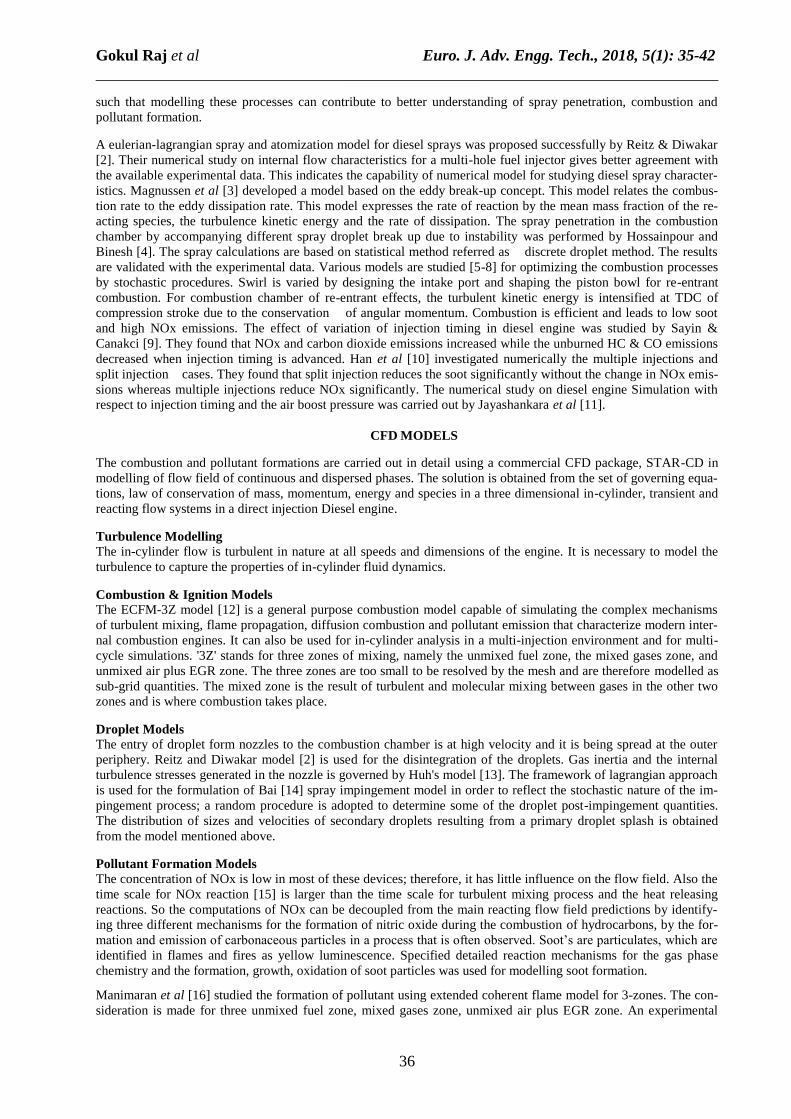
CFD simulation starts with the geometry of the piston bowl. The piston bowl shape is prepared using Solid Works
10 package. The meshing of the in-cylinder fluid domain is performed using ES-ICE (Expert System — Internal
Combustion Engine) Pro-surf tool. In this study, a 120° sector mesh is considered due to symmetry nature of the in-
cylinder domain and thereby the computational time can be reduced considerably. Negative volumes were checked
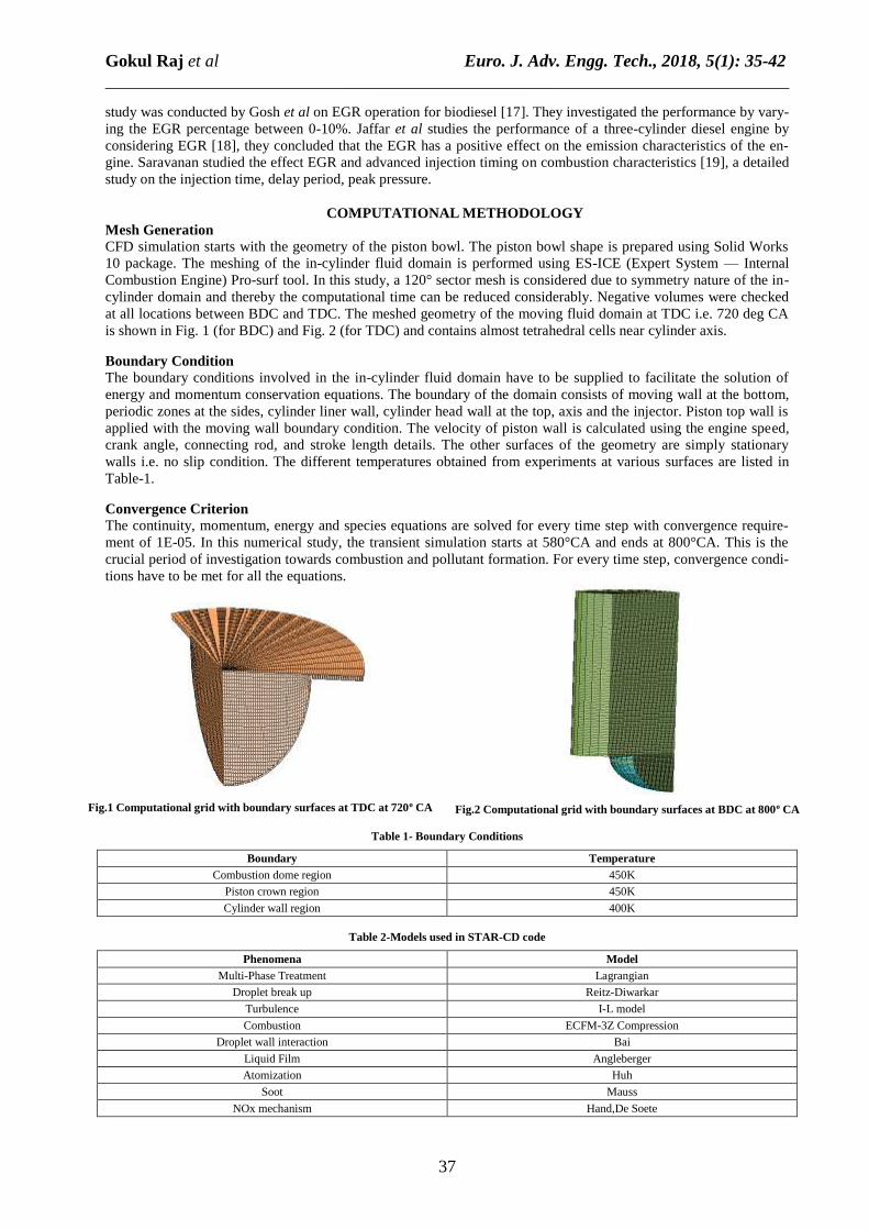
at all locations between BDC and TDC. The meshed geometry of the moving fluid domain at TDC i.e. 720 deg CA
is shown in Fig. 1 (for BDC) and Fig. 2 (for TDC) and contains almost tetrahedral cells near cylinder axis.
Boundary Condition
The boundary conditions involved in the in-cylinder fluid domain have to be supplied to facilitate the solution of
energy and momentum conservation equations. The boundary of the domain consists of moving wall at the bottom,
periodic zones at the sides, cylinder liner wall, cylinder head wall at the top, axis and the injector. Piston top wall is
applied with the moving wall boundary condition. The velocity of piston wall is calculated using the engine speed,
crank angle, connecting rod, and stroke length details. The other surfaces of the geometry are simply stationary
walls i.e. no slip condition. The different temperatures obtained from experiments at various surfaces are listed in
Table-1.
Convergence Criterion
The continuity, momentum, energy and species equations are solved for every time step with convergence require-
ment of 1E-05. In this numerical study, the transient simulation starts at 580°CA and ends at 800°CA. This is the
crucial period of investigation towards combustion and pollutant formation. For every time step, convergence condi-
tions have to be met for all the equations.
Fig.1 Computational grid with boundary surfaces at TDC at 720o CA
Fig.2 Computational grid with boundary surfaces at BDC at 800o CA
Table 1- Boundary Conditions
Boundary Temperature
Combustion dome region 450K
Piston crown region 450K
Cylinder wall region 400K
Table 2-Models used in STAR-CD code
Phenomena Model
Multi-Phase Treatment Lagrangian
Droplet break up Reitz-Diwarkar
Turbulence I-L model
Combustion ECFM-3Z Compression
Droplet wall interaction Bai
Liquid Film Angleberger
Atomization Huh
Soot Mauss
NOx mechanism Hand,De Soete
Gokul Raj et al Euro. J. Adv. Engg. Tech., 2018, 5(1): 35-42
______________________________________________________________________________
38
Solver Details
The stimulation of droplet breaks up and spray droplet break up and spray penetration phenomena is activated using
Lagrangian multiphase treatment. The turbulent dispersion model is included for the droplet to experience randomly
varying velocity field in the cylinder. Collision model [20] is also considered to detect the collision of parcels for
every time step. Gravitational force is also accounted on the droplet parcels. The number of droplet parcels consid-
ered in this work is exceeded beyond 50 million in numbers that enables to study the trajectory, spray penetration
and collision physics. The flame surface density equation is solved by adopting extended coherent flame model for 3
zones namely, the unmixed fuel zone, the mixed gases zone and the unmixed zone of air together with EGR [12].
The complex mechanisms like flame propagation, diffusion combustion and pollutant formations were stimulated
using ECFM-3Z combustion model, solver details are given in Table- 2. A small amount of exhaust gas is mixed
with fresh air and then introduced into the combustion chamber. This modifies the fuel/air ratio and EGR, which
lowers the peak temperature so that the chemical reaction rate between nitrogen and any unused oxygen is strongly
reduced. Species concentrations involved in combustion reactions can .be written as a function of mixture fraction
within the presumed probability density function model of combustion. Phenomenon and the model chosen were
shown in Table-3. The liquid film model [21] accounts for convective transport of conserved quantities within the
film and from/to the gas phase. Spray impingement model [14] is formulated within the framework of the Lagrangi-
an approach to reflect the stochastic nature of the impingement process. A random procedure is adopted to deter-
mine the droplet post-impingement quantities. The standard pool boiling [22] is used to model liquid film boiling,
when the wall temperature exceeds the saturation temperature of the liquid as the film starts to boil when the heat
flux passes from the wall to the film. The injections of fuel start at 714° CA and ends at 722° CA.
Post-Processing
Time step computations are carried out till the residual values of the conservation equations of continuity, momen-
tum and energy fall below 10-5. Auxiliary equations involving the turbulence spray models and models for combus-
tion and emissions are also computed at every time step. The contours of the same quantities are also obtained by
storing the information at pre-set crank-angles.
VALIDATION
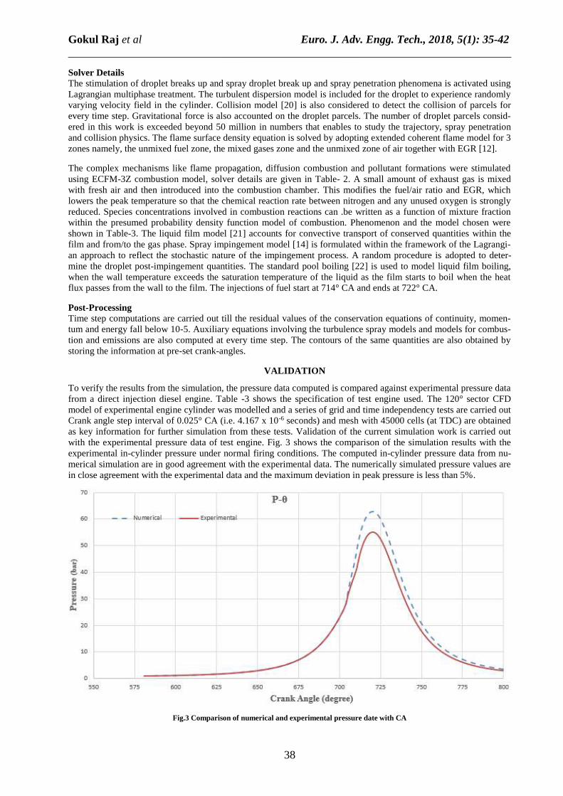
To verify the results from the simulation, the pressure data computed is compared against experimental pressure data
from a direct injection diesel engine. Table -3 shows the specification of test engine used. The 120° sector CFD
model of experimental engine cylinder was modelled and a series of grid and time independency tests are carried out
Crank angle step interval of 0.025° CA (i.e. 4.167 x 10⁻⁶ seconds) and mesh with 45000 cells (at TDC) are obtained
as key information for further simulation from these tests. Validation of the current simulation work is carried out
with the experimental pressure data of test engine. Fig. 3 shows the comparison of the simulation results with the
experimental in-cylinder pressure under normal firing conditions. The computed in-cylinder pressure data from nu-
merical simulation are in good agreement with the experimental data. The numerically simulated pressure values are
in close agreement with the experimental data and the maximum deviation in peak pressure is less than 5%.
Fig.3 Comparison of numerical and experimental pressure date with CA
Gokul Raj et al Euro. J. Adv. Engg. Tech., 2018, 5(1): 35-42
______________________________________________________________________________
39
Table 3- Engine Specifications
Bore 0.080m Fuel Pure Diesel
Stroke 0.1m Injector hole diameter 0.0004m
Compression Ratio 17 Injected mass 0.177kg/s
Connecting Rod Length 0.235m Fuel-air equivalence ratio 0.85
Engine Speed 1500RPM
RESULTS AND DICUSSIONS
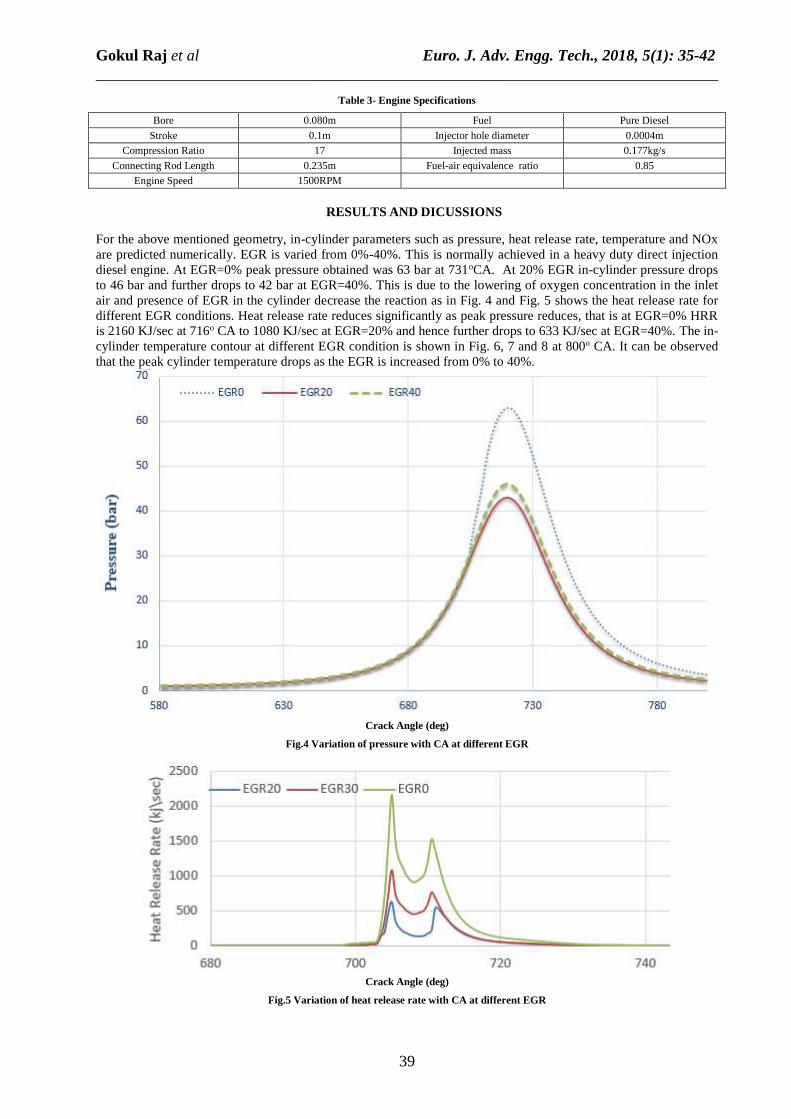
For the above mentioned geometry, in-cylinder parameters such as pressure, heat release rate, temperature and NOx
are predicted numerically. EGR is varied from 0%-40%. This is normally achieved in a heavy duty direct injection
diesel engine. At EGR=0% peak pressure obtained was 63 bar at 731oCA. At 20% EGR in-cylinder pressure drops
to 46 bar and further drops to 42 bar at EGR=40%. This is due to the lowering of oxygen concentration in the inlet
air and presence of EGR in the cylinder decrease the reaction as in Fig. 4 and Fig. 5 shows the heat release rate for
different EGR conditions. Heat release rate reduces significantly as peak pressure reduces, that is at EGR=0% HRR
is 2160 KJ/sec at 716o CA to 1080 KJ/sec at EGR=20% and hence further drops to 633 KJ/sec at EGR=40%. The in-
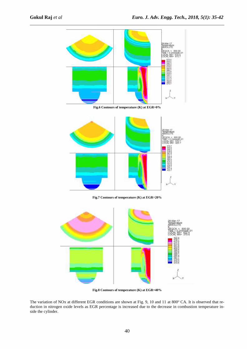
cylinder temperature contour at different EGR condition is shown in Fig. 6, 7 and 8 at 800o CA. It can be observed
that the peak cylinder temperature drops as the EGR is increased from 0% to 40%.
Crack Angle (deg)
Fig.4 Variation of pressure with CA at different EGR
Crack Angle (deg)
Fig.5 Variation of heat release rate with CA at different EGR
Gokul Raj et al Euro. J. Adv. Engg. Tech., 2018, 5(1): 35-42
______________________________________________________________________________
40
Fig.6 Contours of temperature (K) at EGR=0%
Fig.7 Contours of temperature (K) at EGR=20%
Fig.8 Contours of temperature (K) at EGR=40%
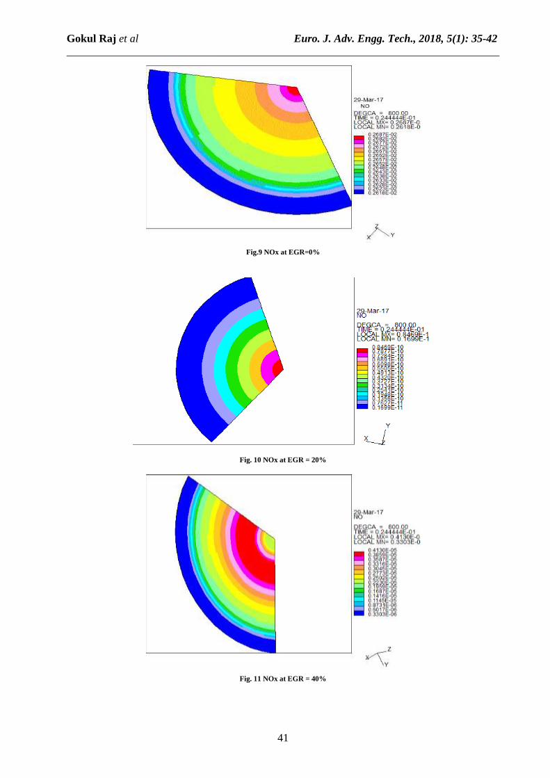
The variation of NOx at different EGR conditions are shown at Fig. 9, 10 and 11 at 800o CA. It is observed that re-
duction in nitrogen oxide levels as EGR percentage is increased due to the decrease in combustion temperature in-
side the cylinder.
Gokul Raj et al Euro. J. Adv. Engg. Tech., 2018, 5(1): 35-42
______________________________________________________________________________
41
Fig.9 NOx at EGR=0%
Fig. 10 NOx at EGR = 20%
Fig. 11 NOx at EGR = 40%

Gokul Raj et al Euro. J. Adv. Engg. Tech., 2018, 5(1): 35-42
______________________________________________________________________________
42
CONCLUSION
Experimental and numerical investigation has been carried out to study the effect of Exhaust Gas Recirculation
(EGR) on the performance of compression ignition engine. Different models governing the direct injection diesel
engine combustion and pollutant formation are studied using simulation software. The results were compared with
the experimental data and the following conclusions were drawn. There is a reduction in peak cylinder pressure ob-
served with the increase of EGR. The peak in-cylinder pressure decreases by 21 bar when EGR is increased from
0% to 40%. The heat release rate follows the same characteristics as that of peak cylinder pressure, Heat release
occurs nearly at 716-degree CA and deceases by 30% when the EGR is increased from 0% to 40%. Reduction in
both in cylinder temperature and NOx formation were observed when EGR levels were increased. This is due to the
fact that EGR admits the inert gases in the chamber which have specific heat higher than that of air so they absorb
the heat of combustion and also dilute the fresh air which increases the ignition delay and hence reduce the heat of
combustion which ultimately result in lower exhaust gas temperature and lower NOx emission. Exhaust gas recircu-
lation (EGR) has been found a very effective way to reduce NOx emission from the diesel engine. EGR is still the
most viable technique that can drastically reduce NOx to meet the emission regulations.
REFERENCES
[1] JB Heywood, International Combustion Engine Fundamentals, McGraw-Hill, New York, 1988, 491-566.
[2] RD Reitz and R Diwakar, Effect of Drop Breakup on Fitel Sprays, SAE Technical Paper Series, 860469, 1986.
[3] BF Magnussen and Hjertager, On Mathematical Modeling of Turbulent Combustion with Special Emphasis on
Soot Formation and Combustion, 16th Symposium on Combustion, The Combustion Institute, 1976, 719-729.
[4] S Hossainpour and AR Rinesh, Investigation of Fuel Spray Atomization in a DI Heavy-Duty Diesel Engine and
Comparison of Various Spray Breakup Models, Fuel, 2009, 88(5), 799-805.
[5] BVVSU Prasad, CS Sharma, TNC Anand and RV Ravikrishna, High Swirl-Inducing Piston Bowls in Small
Diesel Engines for Emission Reduction, Applied Energy RR, 2011, 88(7), 2355-2367.
[6] DM Baker and DN Assanis, A Methodology for Coupled Thermodynamic and Heat Transfer Analysis of a
Diesel Engine, Applied Mathematical Modelling, 1994, 18(11), 590-601.
[7] K Qi, L Emig, X Lang, B Du and W Long, Simulation of Quasi-Dimensional Combustion Model for Predicting
Diesel Engine Performance, Applied Mathematical Modelling, 2011, 35(2), 930-940.
[8] K Park, DM Wang and AP Watkins, A Contribution to the Design of a Novel Direct- Injection Diesel Engine
Combustion System-Analysis of Pip Size, Applied Mathematical Modelling, 1993, 17(3), 114-124.
[9] Cenk Sayin and Mustafa Canakei, Effects of Injection Timing on the Engine Performance and Exhaust
Emissions of a Dual- Fuel Diesel Engine, Energy Conversion & Management, 2009, 50(1), 203-213.
[10] Z Han, A Uludogan, GJ Hampson and RD Reitz, Mechanism of Soot and NOx Emission Reduction Using
Multiple-Injection in a Diesel Engine, 1996, SAE Paper 960633.
[11] B Jayashankara and V Ganesan, Effect of Fuel Injection Timing and Intake Pressure on the Performance of a DI
Diesel Engine - A Parametric Study using CFD, Energy Conversion and Management, 2010, 51(10), 1835-1848.
[12] O Colin and A Benkcnida, The 3-Zone Extended Coherent Flame Model (ECFM3Z) for Computing
Premixed/Diffusion Combustion, Oil & Gas Science and Technology – Review, 2004, 59(6), 593-609.
[13] ICY Huh and AD Gosman, A Phenomenological Model of Diesel Spray Atomisation, Proceedings of
International Conference on Multipham Flows (1CMF '91), Tsukuba, 1991.
[14] C Bai and AD Gosman, Mathematical modeling of wall films formed by impinging sprays, SAE Technical
Paper Series 960626, 1996.
[15] De Soete, Overall Reaction Rang of NO and N1 Formation from Fuel Nitrogen, 15th Symposium International
on Combustion, The Combustion Institute, 1975, 1093-1102.
[16] R Manimaran and R Thundil Karuppa Raj, CFD Analysis of Combustion and Pollutant Formation Phenomena
in a Direct Injection Diesel Engine at Different EGR Condition, Procedia Engineering, 2013, 64, 497-506.
[17] S Gosh and D Dutta, The Effect of EGR on the Performance and Exhaust Emission of a Diesel Engine Operated
on Diesel Oil and Pongamia Piñata Methyl Ester, International Journal of Engineering Inventions, 2012, 1(12), 39-
45.
[18] J Hussain, K Palaniraja, N Alagumurthi and R Manimaran, Effect of EGR on Performance and Emission
Characteristics of a Three Cylinder Direct Injection Compression Ignition Engine, Alexandria Engineering Journal,
2012, 51, 241-248.
[19]S Saravanan, Effect of EGR at Advanced Injection Timing on Combustion Characteristics of Diesel Engine,
Alexandria Engineering Journal, 2015, 54(3), 339-342.
[20] PJ O'Rourke, Collective Drop Effects on vaporizing Liquid Sprays, University of Princeton, USA, 1981.
[21] C Angelberger, T Poinsot and B Delhay, Improving Near-Wall Combustion and Wall Heat Transfer Modeling
in SI Engine Computations, SAE Technical Paper Series 972881, 1997, 113-130.
[22] WM Rohsenow, A Method of Correlating Heat Transfer Data for Surface Boiling Liquids, Transactions of the
ASNIE, 1952, 74, 969.