combitek f 23 e - openclima · note: the time is set in 24 hour format, for example ... the...
TRANSCRIPT

1
THIS IS A CAT II2H3+ APPLIANCE
01773 828100
I N W A R R A N T YT E C H N I C A L H E L P L I N E
01773 828400
COMBITEK F 23 E
Installation and Servicing Instructions
2
USER INSTRUCTIONSINTRODUCTIONThe Combitek F 23 E is a wall mounted combinationboiler providing central heating and instantaneousdomestic hot water.
These instructions should be carefully followed forthe safe and economical use of your boiler.
Gas leak or faultIf a gas leak or fault exists or is suspected, turn theboiler and gas supply off and consult the local gascompany or your Installer/Service provider.
In case of power supply failureThe boiler no longer operates.As soon as power supply is restored, the boiler willrestart automatically.
In case of loss of water in the systemCAUTION. The boiler is installed as part of a sealedsystem which must only be drained and filled by acompetent person.
If the pressure shown on the pressure gauge is lessthan 1.5 bar the system must be filled up.
Important notice: A central heating system cannotoperate satisfactorily unless it is properly filled withwater and unless the air initially contained in thepiping systems has been properly bled off. If theseconditions are not satisfied, air noise will occur withinthe system and the boiler may fail to operate.
Air in the heating systemPersistent air in the heating system may indicateleaks in the system or corrosion taking place. Callyour Installer/Service provider.
Overheating safetyIn the event of problem, the overheat safety devicecauses safety shutdown of the boiler. If this happens,call your Installer/Service provider.
INSTALLATION AND SERVICING INSTRUCTIONS
COMBITEK F 23 E
Mandatory warning for CE countriesWARNING, these appliances were designed, approved and inspected to meet the requirements of the
English market. The identification plate located on the inside of the appliance certifies the origin where theproduct was manufactured and the country for which it is intended.If you see any exception to this rule, please contact your nearest stockist.Thank you in advance for your assistance.
UK
Note: The boiler serial number is marked on the data label attached to the PCB housing behind the frontlower section. Refer to the ‘Introduction’ section for a description of the basic functions of the boiler. The
‘User’ section describes how to safely operate the boiler.
Users’ InstructionsIntroduction ..................................................... Page 2Controls and lighting ................................................. 3Draining and filling ..................................................... 3Heating safety valve ................................................. 3Servicing/maintenance ............................................ 3Cleaning ..................................................................... 4Boiler casing ............................................................... 4
Installation InstructionsIntroduction ..................................................... Page 4Changing gas type ................................................... 4Technical data ...................................................... 4 - 5Dimensions .................................................................. 5Boiler schematic ........................................................ 6Terminal positions ....................................................... 7
Heating and hot water system design .................... 7Boiler installation ........................................................ 8Horizontal flue installation ......................................... 9Vertical flue installation ........................................... 10Electrical connection .............................................. 11Commissioning ......................................................... 12Adjustments .............................................................. 13Safety device ........................................................... 13Setting ....................................................................... 14
Servicing InstructionsRoutine cleaning and inspection ............... Page 15Replacement of parts ...................................... 16 - 21Schematic wiring diagram ..................................... 22Fault finding ....................................................... 23 - 24Spare sparts .............................................................. 24
3
2
3
4
5
1
1
19
13
7
20
2
14
8
21
3
15
9
224
16
10
23
5
17
11
24
6
18
12
12
9
6 0
I
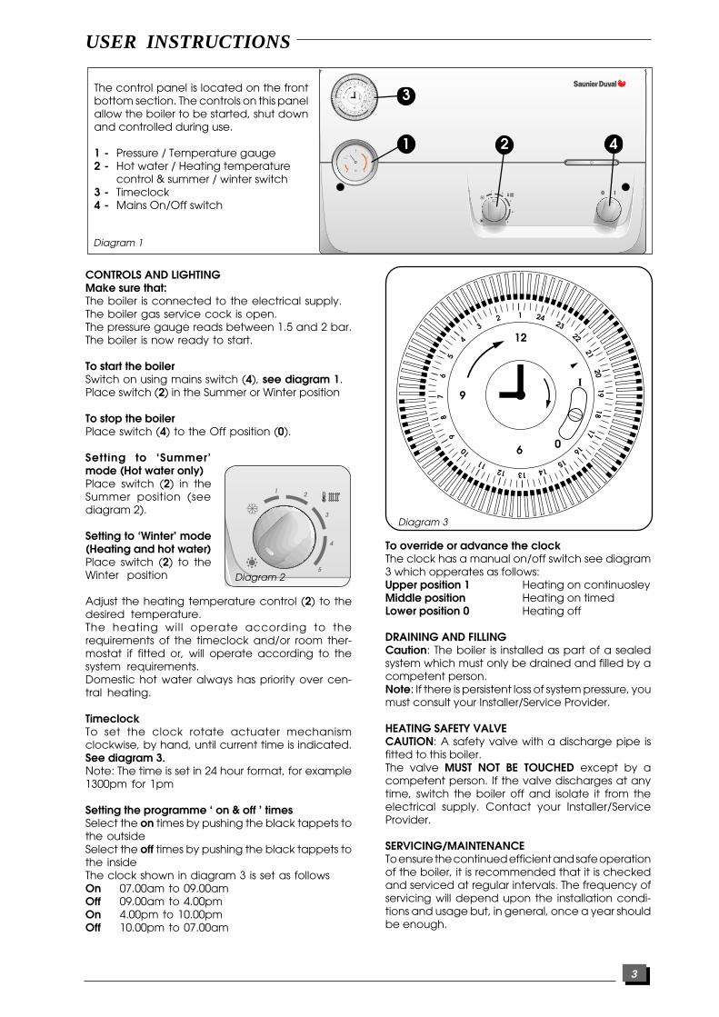
Diagram 1
21
3
4
CONTROLS AND LIGHTINGMake sure that:The boiler is connected to the electrical supply.The boiler gas service cock is open.The pressure gauge reads between 1.5 and 2 bar.The boiler is now ready to start.
To start the boilerSwitch on using mains switch (4), see diagram 1.Place switch (2) in the Summer or Winter position
To stop the boilerPlace switch (4) to the Off position (0).
Setting to ‘Summer’mode (Hot water only)Place switch (2) in theSummer position (seediagram 2).
Setting to ‘Winter’ mode(Heating and hot water)Place switch (2) to theWinter position
Adjust the heating temperature control (2) to thedesired temperature.The heating will operate according to therequirements of the timeclock and/or room ther-mostat if fitted or, will operate according to thesystem requirements.Domestic hot water always has priority over cen-tral heating.
TimeclockTo set the clock rotate actuater mechanismclockwise, by hand, until current time is indicated.See diagram 3.Note: The time is set in 24 hour format, for example1300pm for 1pm
Setting the programme ‘ on & off ’ timesSelect the on times by pushing the black tappets tothe outsideSelect the off times by pushing the black tappets tothe insideThe clock shown in diagram 3 is set as followsOn 07.00am to 09.00amOff 09.00am to 4.00pmOn 4.00pm to 10.00pmOff 10.00pm to 07.00am
2
3
4
5
1
Diagram 2
1
19
13
7
20
2
14
8
21
3
15
9
224
16
10
23
5
17
11
24
6
18
12
12
9
6 0
I
Diagram 3
To override or advance the clockThe clock has a manual on/off switch see diagram3 which opperates as follows:Upper position 1 Heating on continuosleyMiddle position Heating on timedLower position 0 Heating off
DRAINING AND FILLINGCaution: The boiler is installed as part of a sealedsystem which must only be drained and filled by acompetent person.Note: If there is persistent loss of system pressure, youmust consult your Installer/Service Provider.
HEATING SAFETY VALVECAUTION: A safety valve with a discharge pipe isfitted to this boiler.The valve MUST NOT BE TOUCHED except by acompetent person. If the valve discharges at anytime, switch the boiler off and isolate it from theelectrical supply. Contact your Installer/ServiceProvider.
SERVICING/MAINTENANCETo ensure the continued efficient and safe operationof the boiler, it is recommended that it is checkedand serviced at regular intervals. The frequency ofservicing will depend upon the installation condi-tions and usage but, in general, once a year shouldbe enough.
The control panel is located on the frontbottom section. The controls on this panelallow the boiler to be started, shut downand controlled during use.
1 - Pressure / Temperature gauge2 - Hot water / Heating temperature
control & summer / winter switch3 - Timeclock4 - Mains On/Off switch
USER INSTRUCTIONS
4
CLEANINGThe boiler casing can be cleaned with a damp clothfollowed by a dry cloth to polish.Do not use abrasive or solvent cleaners.
BOILER CASINGCAUTION: Do not remove or adjust the casing in anyway, as incorrect fitting may result in faulty operation.If in doubt, contact your Installer/Service Provider.
INSTALLATION INSTRUCTIONSINTRODUCTIONThe Combitek F 23 E is a wall mounted combinationboiler providing central heating and instantaneousdomestic hot water.Note: this boiler requires no fixing jig and has topoutlet flueing only ( there is no rear flue option ).
The boiler is of the II2H3+ category for use withNatural gas (G20). To convert to Butane (G30) orpropane (G31), the following kit is required.Gas conversion kit :part number 86161
The boiler has a fan assisted, balanced, flue whichboth discharges the product of combustion to, anddraws the combustion air from, the outside of thebuilding.
AccessoriesA range of accessories are available including,vertical flue components. For further information,contact you nearest stockist.
Gas Safety (Installation and Use) RegulationsIn the interests of gas safety, it is the law that ALL gasappliances are installed and serviced in by acompetent person in accordance with the aboveregulations.
Gas leak or faultIf a gas leak or fault exists or is suspected, turn off theboiler and gas supply and consult the local gascompany or your Installer/Service Provider.
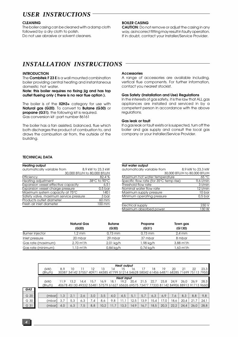
Heating outputautomatically variable from 8,9 kW to 23,3 kW
30,000 BTU/H to 80,000 BTU/HEfficiency 82,4 %Heating adjustment 38°C to 90°CExpansion vessel effective capacity 6,5 lExpansion vessel charge pressure 0,5 barMaximum system capacity at 75°C 140 lSafety valve, maximum service pressure 3 barProducts outlet diameter 60 mmFresh air inlet diameter 100 mm
Hot water outputautomatically variable from 8,9 kW to 23,3 kW
30,000 BTU/H to 80,000 BTU/HMaximum hot water temperature 65 °CSpecific flow rate (for 35°C temp rise) 9,6 l/minThreshold flow rate 3 l/minNominal water flow rate 12 l/minMaximum supply pressure 10 barMinimum operating pressure 0,5 bar
Electrical supply 230 VMaximum absorbed power 130 W
Natural Gas Butane Propane Town gas(G20) (G30) (G31) (G130)
Burner injector 1,2 mm 0,73 mm 0,73 mm 2,4 mm
Inlet pressure 20 mbar 29 mbar 37 mbar 8 mbar
Gas rate (maximum) 2,70 m3/h 2,01 kg/h 1,98 kg/h 3,88 m3/h
Gas rate (minimum) 1,13 m3/h 0,84 kg/h 0,74 kg/h 1,63 m3/h
Heat output(kW) 8,9 10 11 12 13 14 15 16 17 18 19 20 21 22 23,3
(Btu/h) 30387 34142 37557 40971 44385 47799 51214 54628 58042 61456 64871 68285 71699 75113 79552
Heat input(kW) 11,9 13,2 14,4 15,7 16,9 18,1 19,2 20,4 21,5 22,7 23,8 24,9 26,0 26,9 28,3
(Btu/h) 40678 45130 49332 53481 57579 61627 65626 69575 73477 77333 81142 84906 88913 91713 96602GAS
G 20 (mbar) 1,3 2,1 2,6 3,0 3,5 4,0 4,5 5,1 5,7 6,3 6,9 7,6 8,3 8,8 9,8
G 30 (mbar) 3,7 5,3 6,3 7,4 8,6 9,8 11,1 12,5 13,9 15,4 17,0 18,6 20,4 21,7 24,1
G 31 (mbar) 4,0 6,3 7,5 8,8 10,2 11,7 13,3 14,9 16,7 18,5 20,3 22,2 24,4 26,0 28,8
USER INSTRUCTIONS
TECHNICAL DATA

5
Ava
ilab
le p
ress
ure
(kP
a)
be
twe
en
hea
ting
flo
w a
nd re
turn
(10 kPa = 1 m WG)
12
345
Bypass fully shut
Open 1/4 turn
Open 1/2 turn
Open 1 turn
Open 2 turns
50
40
30
20
10
0 500 1000
1
23
5
4
Flow rate through heating system (I/h)
Po
m 0
52
Pump:The performance of the pump varies according to the pump bypass setting, see diagram 3.
Diagram 3
Diagram 4
Ha
b 2
71a
Net weight: 41 kgGross weight: 43 kg
The boiler is delivered in twoseparate packages:- The boiler- The flue system
ClearancesThe boiler can be installed withthe following clearances:50 mm either side of the boiler600 mm to the front of the boiler300 mm below the boiler
378410
857
23462
3802
INSTALLATION INSTRUCTIONS
DIMENSIONS

6
Shy
131b
3 - Ignition module4 - Heating temperature adjuster6 - Pressure gauge7 - non-return valve8 - Expansion vessel9 - Pump
10 - Automatic air vent11 - Burner12 - Burner pressure test point13 - Heat exchanger14 - Gas valve16 - Heating and hot water thermistor17 - Ignition electrode
19 - Overheat thermostat20 - Flame sense electrode21 - Loss of water pressure switch22 - Fan23 - Air pressure switch24 - Gas cock
A - Heating returnB - Cold water inletC - Heating flowD - Domestic hot water flowE - Gas supply
Diagram 5
INSTALLATION INSTRUCTIONS
BOILER SCHEMATIC
A B C D E
23 22
19
17
16
14
3
4
24
13
20
11
12
10
9
8
7
6
21
7
NC
D
M
AB
E F
G
I HL
Ve
n 0
60b
Diagram 6
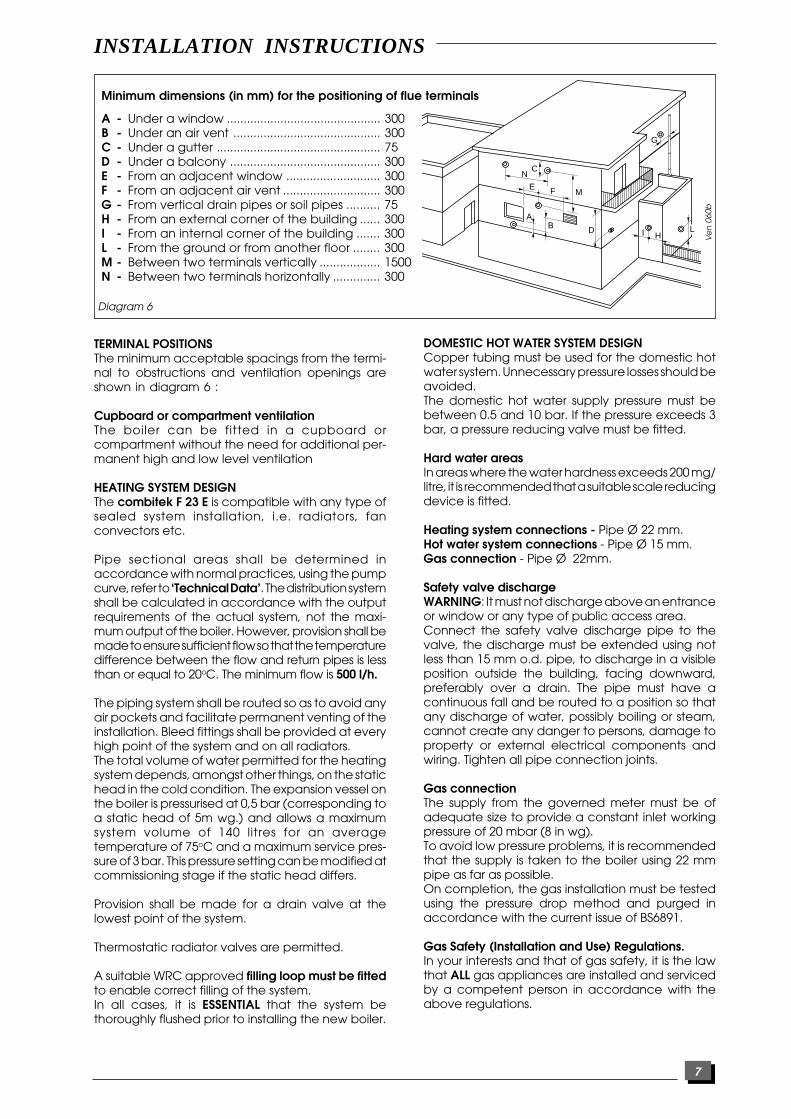
Minimum dimensions (in mm) for the positioning of flue terminals
A - Under a window .............................................. 300B - Under an air vent ............................................ 300C - Under a gutter ................................................. 75D - Under a balcony ............................................. 300E - From an adjacent window ............................ 300F - From an adjacent air vent ............................. 300G - From vertical drain pipes or soil pipes .......... 75H - From an external corner of the building ...... 300I - From an internal corner of the building ....... 300L - From the ground or from another floor ........ 300M - Between two terminals vertically .................. 1500N - Between two terminals horizontally .............. 300
TERMINAL POSITIONSThe minimum acceptable spacings from the termi-nal to obstructions and ventilation openings areshown in diagram 6 :
Cupboard or compartment ventilationThe boiler can be fitted in a cupboard orcompartment without the need for additional per-manent high and low level ventilation
HEATING SYSTEM DESIGNThe combitek F 23 E is compatible with any type ofsealed system installation, i.e. radiators, fanconvectors etc.
Pipe sectional areas shall be determined inaccordance with normal practices, using the pumpcurve, refer to ‘Technical Data’. The distribution systemshall be calculated in accordance with the outputrequirements of the actual system, not the maxi-mum output of the boiler. However, provision shall bemade to ensure sufficient flow so that the temperaturedifference between the flow and return pipes is lessthan or equal to 20oC. The minimum flow is 500 l/h.
The piping system shall be routed so as to avoid anyair pockets and facilitate permanent venting of theinstallation. Bleed fittings shall be provided at everyhigh point of the system and on all radiators.The total volume of water permitted for the heatingsystem depends, amongst other things, on the statichead in the cold condition. The expansion vessel onthe boiler is pressurised at 0,5 bar (corresponding toa static head of 5m wg.) and allows a maximumsystem volume of 140 litres for an averagetemperature of 75oC and a maximum service pres-sure of 3 bar. This pressure setting can be modified atcommissioning stage if the static head differs.
Provision shall be made for a drain valve at thelowest point of the system.
Thermostatic radiator valves are permitted.
A suitable WRC approved filling loop must be fittedto enable correct filling of the system.In all cases, it is ESSENTIAL that the system bethoroughly flushed prior to installing the new boiler.
DOMESTIC HOT WATER SYSTEM DESIGNCopper tubing must be used for the domestic hotwater system. Unnecessary pressure losses should beavoided.The domestic hot water supply pressure must bebetween 0.5 and 10 bar. If the pressure exceeds 3bar, a pressure reducing valve must be fitted.
Hard water areasIn areas where the water hardness exceeds 200 mg/litre, it is recommended that a suitable scale reducingdevice is fitted.
Heating system connections - Pipe Ø 22 mm.Hot water system connections - Pipe Ø 15 mm.Gas connection - Pipe Ø 22mm.
Safety valve dischargeWARNING: It must not discharge above an entranceor window or any type of public access area.Connect the safety valve discharge pipe to thevalve, the discharge must be extended using notless than 15 mm o.d. pipe, to discharge in a visibleposition outside the building, facing downward,preferably over a drain. The pipe must have acontinuous fall and be routed to a position so thatany discharge of water, possibly boiling or steam,cannot create any danger to persons, damage toproperty or external electrical components andwiring. Tighten all pipe connection joints.
Gas connectionThe supply from the governed meter must be ofadequate size to provide a constant inlet workingpressure of 20 mbar (8 in wg).To avoid low pressure problems, it is recommendedthat the supply is taken to the boiler using 22 mmpipe as far as possible.On completion, the gas installation must be testedusing the pressure drop method and purged inaccordance with the current issue of BS6891.
Gas Safety (Installation and Use) Regulations.In your interests and that of gas safety, it is the lawthat ALL gas appliances are installed and servicedby a competent person in accordance with theabove regulations.
INSTALLATION INSTRUCTIONS
8
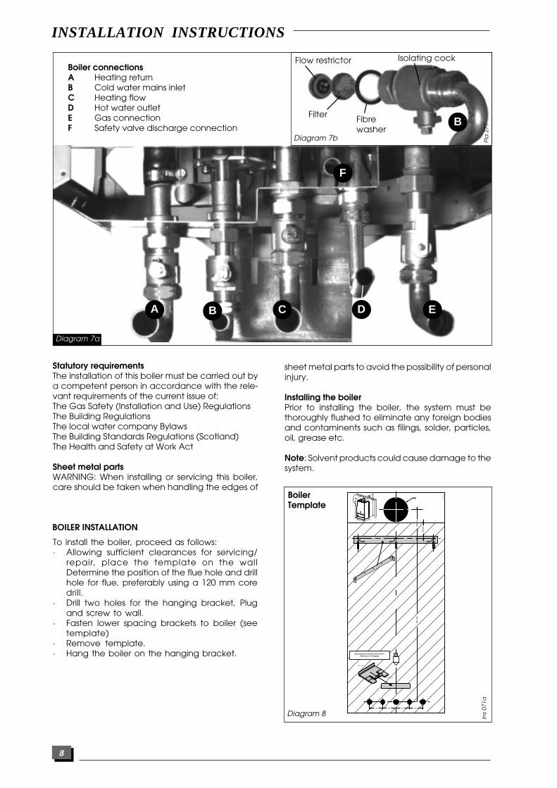
Statutory requirementsThe installation of this boiler must be carried out bya competent person in accordance with the rele-vant requirements of the current issue of:The Gas Safety (Installation and Use) RegulationsThe Building RegulationsThe local water company BylawsThe Building Standards Regulations (Scotland)The Health and Safety at Work Act
Sheet metal partsWARNING: When installing or servicing this boiler,care should be taken when handling the edges of
Boiler connectionsA Heating returnB Cold water mains inletC Heating flowD Hot water outletE Gas connectionF Safety valve discharge connection
Pla
275
A B C D E
Diagram 7a
BDiagram 7b P
la 2
77
Isolating cockFlow restrictor
Filter Fibrewasher
sheet metal parts to avoid the possibility of personalinjury.
Installing the boilerPrior to installing the boiler, the system must bethoroughly flushed to eliminate any foreign bodiesand contaminents such as filings, solder, particles,oil, grease etc.
Note: Solvent products could cause damage to thesystem.
To install the boiler, proceed as follows:· Allowing sufficient clearances for servicing/
repair, place the template on the wallDetermine the position of the flue hole and drillhole for flue, preferably using a 120 mm coredrill.
· Drill two holes for the hanging bracket, Plugand screw to wall.
· Fasten lower spacing brackets to boiler (seetemplate)
· Remove template.· Hang the boiler on the hanging bracket.
Ins
071a
Diagram 8
BoilerTemplate
INSTALLATION INSTRUCTIONS
BOILER INSTALLATION
F
378410
857
234
802
1106
65 B
Ø 105
Ø 8Ø 8 Ø 8
55 55 57,5 57,5
691
mm
WALL SIDE
BOILER SIDE
Spacing plate must be attached to boiler prior to hanging
120
mm
65 m
m

9
HORIZONTAL FLUE INSTALLATION• Fit gasket (H) onto underside of elbow (C)• Carefully insert ‘o’ rings (J) into upper and lower
parts of inner elbow• Fit elbow onto boiler using screws provided (I)• Offer flue pipes to elbow, note that pipe (B) should
be inside pipe (A) before connection. Push pipe(B) into inner elbow socket and connect pipe (A)with collar (D). Locking clips (E) are used to lockcollar into position.
• Parts (F) and (G) are used to seal brickwork gapsif required. If using part (G) to seal inner wall, thisshould be placed over flue before installation.
Calculation of flue cutting lengths· Measure wall thickness e (mm)· For side flues, measure distance from inside face of
the side wall to the centre line of the boiler andsubtract 205 mm to get dimension a (mm) seediagram 10.
· Refere to table 1 for the cutting lenghs of boththe inner and outer flue pipes for each of thevarious flue options available.
· Important: All flue cutting lengths must bemeasured from the terminal end of the flue pipes,see diagram 11.
· When the dimension x measured on site is greaterthan that given in table 1 a flue extension kit will berequired, refere to table 2 for details.
INSTALLATION INSTRUCTIONS
Diagram 9 Ph
o 4
22
The flue kit 86285 is 1000 mm long and com-prises:- Outer pipe .................................................... A- Inner pipe ....................................................... B- Flue elbow..................................................... C- Fixing collar ................................................... D- Locking clips .................................................. E- External rubber sealing collar ..................... F- Internal flange .............................................. G- Gasket ........................................................... H- Screws .............................................................. I- 'O' rings ........................................................... J
A
B
I
GEC
F
JH
D
Table 1Flue cutting lengths
Cutting length (mm)
Flue option outer pipe inner pipe Comments
Top outlet e + 144 e + 224 maximumrear flue wall thickness "e"
withoutextension511 mm
Table 2Number of extension kits required
Flue option Dimension 'X' No. ofextension kits
Side flue 745 to 1745 mm 1(left or right) 1527 to 2745 mm 2
Ha
b 2
10
Diagram 10
ee aa
XX
Ve
n 0
89
Diagram 11
Cutting length
Outer pipe
Inner pipe
Cutting length
Maximum horizontal flue run 3mFor each 90o flue bend fitted, reduce overall fluelength by 1 m.For each 45o flue bend fitted, reduce overall fluelength by 0.5 m.
Horizontal flue kit 86285Flue extension kit 8509190o bend kit 8509245o bend kit 85093
10
INSTALLATION INSTRUCTIONS
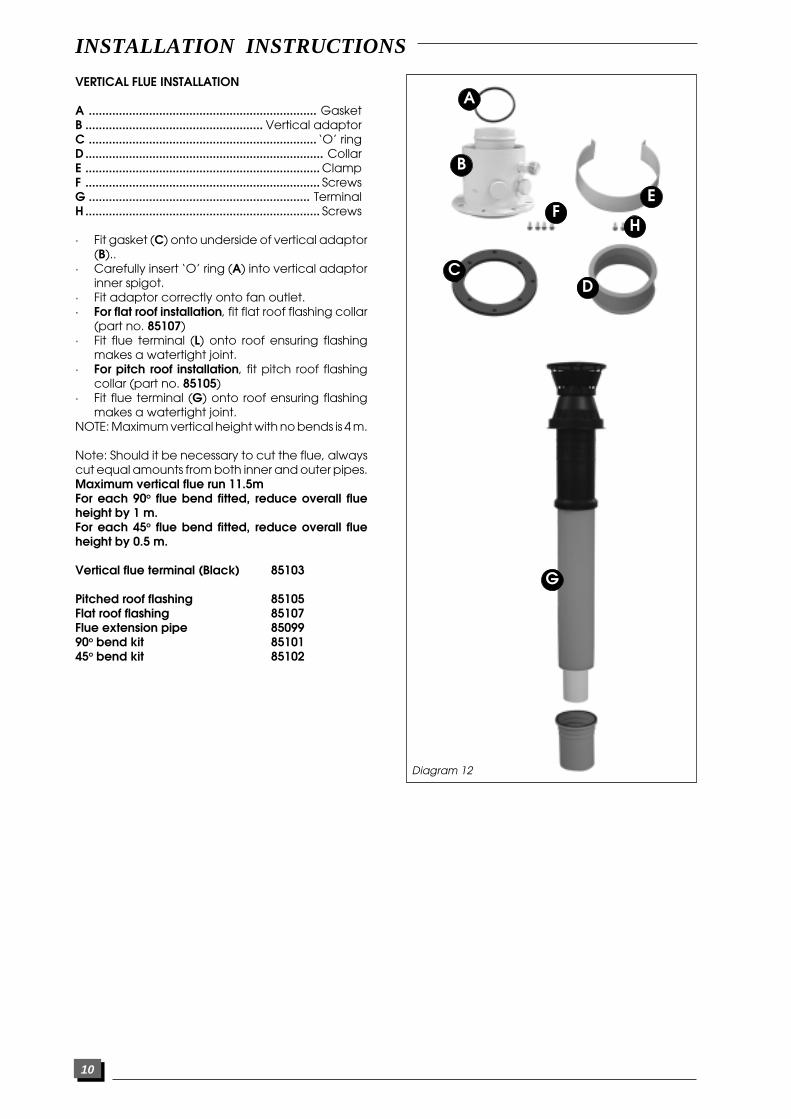
VERTICAL FLUE INSTALLATION
A .................................................................... GasketB ..................................................... Vertical adaptorC .................................................................... ‘O’ ringD....................................................................... CollarE ...................................................................... ClampF ...................................................................... ScrewsG .................................................................. TerminalH ...................................................................... Screws
· Fit gasket (C) onto underside of vertical adaptor(B)..
· Carefully insert ‘O’ ring (A) into vertical adaptorinner spigot.
· Fit adaptor correctly onto fan outlet.· For flat roof installation, fit flat roof flashing collar
(part no. 85107)· Fit flue terminal (L) onto roof ensuring flashing
makes a watertight joint.· For pitch roof installation, fit pitch roof flashing
collar (part no. 85105)· Fit flue terminal (G) onto roof ensuring flashing
makes a watertight joint.NOTE: Maximum vertical height with no bends is 4 m.
Note: Should it be necessary to cut the flue, alwayscut equal amounts from both inner and outer pipes.Maximum vertical flue run 11.5mFor each 90o flue bend fitted, reduce overall flueheight by 1 m.For each 45o flue bend fitted, reduce overall flueheight by 0.5 m.
Vertical flue terminal (Black) 85103
Pitched roof flashing 85105Flat roof flashing 85107Flue extension pipe 8509990o bend kit 8510145o bend kit 85102
Diagram 12Show vertical kit adaptor & terminal
Diagram 12
A
B
E
C
FH
D
G

11
ELECTRICAL CONNECTION
Warning: This boiler must be earthed.All system components must be of an approvedtype.Connection of the whole electrical system and anyheating system controls to the electrical supply mustbe through a common isolator.Isolation should preferably be by a double poleswitched fuse spur box having a minimum contactseparation of 3 mm on each pole. The fused spurbox should be readily accessible and preferablyadjacent to the boiler. It should be identified as to itsuse.A fused three pin plug and shuttered socket outletmay be used instead of the fused spur box, providedthat:a) They are not used in a room containing a bath or
shower.b) Both the plug and socket comply with the current
issue of BS1363.The mains electrical supply must be maintained atall times in order to provide domestic hot water andfrost protection
Note: For further information, see The BuildingRegulations 1991 - Conservation of fuel and power- 1995 edition - Appendix G, table 4b.
INSTALLATION INSTRUCTIONS
DO NOT INTERRUPT THE MAINS SUPPLY TO THE BOILERWITH A TIME SWITCH OR PROGRAMMER.
The combitek F 23 E is delivered with 1metre mainssupply lead ready connected.
External controlsThe boiler will work for heating AS DELIVERED withouta room thermostat fitted provided the two wires onthe integral external controls connection REMAINLINKED TOGETHER (as supplied).If a room thermostat is required, it must be connectedas shown below and the link must be removed.ANY ROOM THERMOSTAT USED MUST BE OF THE VOL-TAGE FREE TYPE.
WARNING: ON NO ACCOUNT MUST ANY ELECTRICALVOLTAGE BE APPLIED TO EITHER OF THE TERMINALS OFTHE EXTERNAL CONTROLS CONNECTIONWARNING: This boiler must be wired in accordancewith these instructions. Any fault arising from incor-rect wiring cannot be put right under the terms of theguarantee.
sch
229
sch
228
E
°CFor no external controls
leave wire link (E) in place
When fitting an external control,remove wire link (E) and connectvoltage free thermostat as shown
Diagram 13
The mains electrical cable is suppliedwith the boiler. It is coiled and tucked
inside the boiler
sch
227

12
Important:- If this procedure is not carried out properly, the boilerwill go into safety lock-out until all of the air has beenpurged.- When venting air from boiler, do not touch theschrader valve on the expansion vessel, it is NOT avent.- Before starting the boiler, turn the pump impellor tomake sure it is free to move.• Unscrew black cap on front of pump.• Using screwdriver, push in pump spindle and turnpump impellor 3 to 4 times. DO NOT HIT SPINDLE. Re-place black cap.
Starting the boilerBefore starting the boiler check that:- The gas meter tap is open. If using Butane or Pro-pane, check that valve on storage cylinder or tank isopen.- You have removed the two fan transit clips from fan.
The commissioning and first firing of the boiler mustonly be done by a competent person.
Gas installationIt is recommended that any air is purged from thesupply at the gas inlet test point on the left handside of the gas valve, see diagram 14.
- The boiler gas service cock is open.- The boiler is connected to the electrical supply andswitched on.- The front casing is fitted.
First starting up• Following the instructions given in the 'User Instruc-tions' set boiler to run in central heating mode.• Set boiler thermostat for maximum temperatureensure timeclock is "ON" and check that any exter-nal controls, if fitted, are calling for heat.• Allow the temperature to rise to the maximumvalue, with all radiator valves open.The temperature rise will cause release of the gasescontained in the water of central heating system.- Gases driven towards the boiler will be automati-cally released through the automatic air vents.- Gases trapped at the highest point of the systemmust be released by bleeding the radiators.
Diagram 14Filling the system
Open isolating coks to boiler(see diagram 7a)
Sec
058
6
Sec
058
Make sure thatpressure gauge
reads between 1 and2 bar. Re-pressurisesystem as necessary.
5 Open varioushot water taps to
bleed system.
Ins
062
Ins
061
4 Bleed each radiator until a continu-
ous jet of water is ob-tained.
2
3
Open the tap on the sys-tem filling loop and fill thesystem until the pressureindicated on the displayis between 1 and 2 bar.
Undo, but do notremove, cap onautomatic airvent on top ofpump. Do not re-tighten cap.
Re
g 0
08m
ec
117
1
COMMISSIONING
INSTALLATION INSTRUCTIONS
13
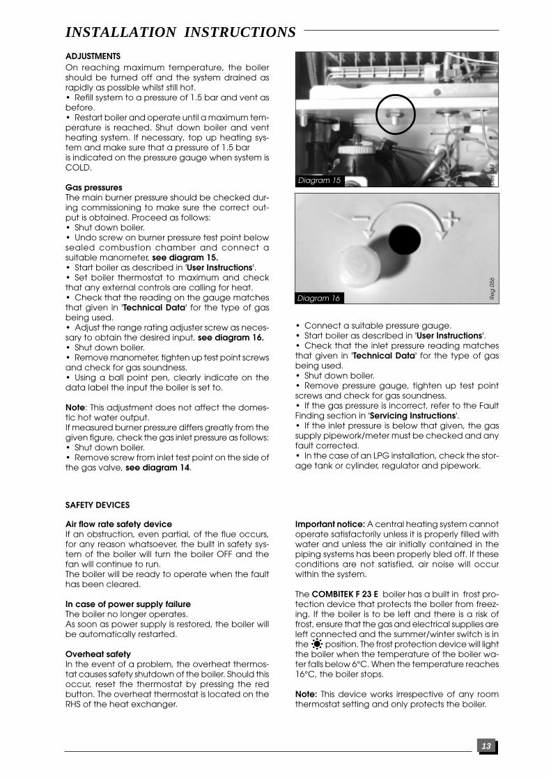
On reaching maximum temperature, the boilershould be turned off and the system drained asrapidly as possible whilst still hot.• Refill system to a pressure of 1.5 bar and vent asbefore.• Restart boiler and operate until a maximum tem-perature is reached. Shut down boiler and ventheating system. If necessary, top up heating sys-tem and make sure that a pressure of 1.5 baris indicated on the pressure gauge when system isCOLD.
Gas pressuresThe main burner pressure should be checked dur-ing commissioning to make sure the correct out-put is obtained. Proceed as follows:• Shut down boiler.• Undo screw on burner pressure test point belowsealed combustion chamber and connect asuitable manometer, see diagram 15.• Start boiler as described in 'User Instructions'.• Set boiler thermostat to maximum and checkthat any external controls are calling for heat.• Check that the reading on the gauge matchesthat given in 'Technical Data' for the type of gasbeing used.• Adjust the range rating adjuster screw as neces-sary to obtain the desired input, see diagram 16.• Shut down boiler.• Remove manometer, tighten up test point screwsand check for gas soundness.• Using a ball point pen, clearly indicate on thedata label the input the boiler is set to.
Note: This adjustment does not affect the domes-tic hot water output.If measured burner pressure differs greatly from thegiven figure, check the gas inlet pressure as follows:• Shut down boiler.• Remove screw from inlet test point on the side ofthe gas valve, see diagram 14.
De
s 04
4R
eg
056
• Connect a suitable pressure gauge.• Start boiler as described in 'User Instructions'.• Check that the inlet pressure reading matchesthat given in 'Technical Data' for the type of gasbeing used.• Shut down boiler.• Remove pressure gauge, tighten up test pointscrews and check for gas soundness.• If the gas pressure is incorrect, refer to the FaultFinding section in 'Servicing Instructions'.• If the inlet pressure is below that given, the gassupply pipework/meter must be checked and anyfault corrected.• In the case of an LPG installation, check the stor-age tank or cylinder, regulator and pipework.
Diagram 15
Diagram 16
SAFETY DEVICES
Air flow rate safety deviceIf an obstruction, even partial, of the flue occurs,for any reason whatsoever, the built in safety sys-tem of the boiler will turn the boiler OFF and thefan will continue to run.The boiler will be ready to operate when the faulthas been cleared.
In case of power supply failureThe boiler no longer operates.As soon as power supply is restored, the boiler willbe automatically restarted.
Overheat safetyIn the event of a problem, the overheat thermos-tat causes safety shutdown of the boiler. Should thisoccur, reset the thermostat by pressing the redbutton. The overheat thermostat is located on theRHS of the heat exchanger.
Important notice: A central heating system cannotoperate satisfactorily unless it is properly filled withwater and unless the air initially contained in thepiping systems has been properly bled off. If theseconditions are not satisfied, air noise will occurwithin the system.
The COMBITEK F 23 E boiler has a built in frost pro-tection device that protects the boiler from freez-ing. If the boiler is to be left and there is a risk offrost, ensure that the gas and electrical supplies areleft connected and the summer/winter switch is inthe position. The frost protection device will lightthe boiler when the temperature of the boiler wa-ter falls below 6°C. When the temperature reaches16°C, the boiler stops.
Note: This device works irrespective of any roomthermostat setting and only protects the boiler.
ADJUSTMENTS
INSTALLATION INSTRUCTIONS
14
SETTINGS
Me
c 1
21
Re
g 0
13R
eg
057
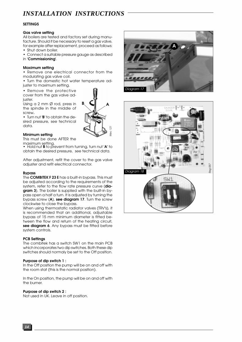
Gas valve settingAll boilers are tested and factory set during manu-facture. Should it be necessary to reset a gas valve,for example after replacement, proceed as follows:• Shut down boiler.• Connect a suitable pressure gauge as describedin 'Commissioning'.
Maximum setting• Remove one electrical connector from themodulating gas valve coil.• Turn the domestic hot water temperature ad-juster to maximum setting.
Diagram 17
Diagram 18
A
• Remove the protectivecover from the gas valve ad-juster.Using a 2 mm Ø rod, press inthe spindle in the middle ofscrew.• Turn nut 'B' to obtain the de-sired pressure, see technicaldata.
Minimum settingThis must be done AFTER themaximum setting.• Hold nut B to prevent from turning, turn nut 'A' toobtain the desired pressure, see technical data.
After adjustment, refit the cover to the gas valveadjuster and refit electrical connector.
BypassThe COMBITEK F 23 E has a built-in bypass. This mustbe adjusted according to the requirements of thesystem, refer to the flow rate pressure curve (dia-gram 3). The boiler is supplied with the built-in by-pass open a half a turn. It is adjusted by turning thebypass screw (A), see diagram 17. Turn the screwclockwise to close the bypass.When using thermostatic radiator valves (TRV's), itis recommended that an additional, adjustablebypass of 15 mm minimum diameter is fitted be-tween the flow and return of the heating circuit,see diagram 6. Any bypass must be fitted beforesystem controls.
PCB SettingsThe combitek has a switch SW1 on the main PCBwhich incorporates two dip switches. Both these dipswitches should normaly be set to the Off position.
Purpose of dip switch 1 :In the Off position the pump will be on and off withthe room stat (this is the normal position).
In the On position, the pump will be on and off withthe burner.
Purpose of dip switch 2 :Not used in UK. Leave in off position.
B
A
INSTALLATION INSTRUCTIONS
15
SERVICING INSTRUCTIONSROUTINE CLEANING ANS INSPECTIONTo ensure the continued efficient and safe opera-tion of the boiler it is recommended that it ischecked and serviced at regular intervals. The fre-quency of servicing will depend upon the particu-lar installation conditions and usage, but in gen-eral once a year should be enough.
It is the law that any servicing is carried out by acompetent person.
Service Check and Preparation.• Operate boiler and check for any faults thatneed to be put right.• Isolate boiler from the gas and electrical supplies.• On completion check all gas carrying parts forsoundness with leak detection fluid.• The maximum domestic hot water flow rate is 12litres/minute.• Remove boiler casing as follows:
Upper front panel• Disengage the two 'quarter turn' fasteners byturning the heads of the screws a quarter of a turntowards the centre of the boiler.• Carefully lower the panel down on its hinge untilit is horizontal.• Turn both plastic catches to release upper frontpanel.• Remove upper front panel by pulling forward atthe bottom and lifting off.Note: The upper front panel is retained by a plasticsafety strap, disengage this before removal.
Side panels• From below boiler, unscrew and remove blackplastic screws securing side panels to the boiler.• Prise out black plastic inserts and lift panel offboiler.
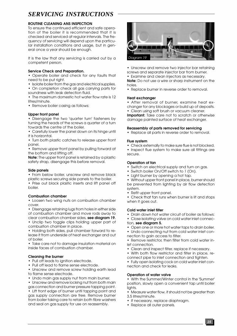
Combustion chamber• Loosen two wing nuts on combustion chambercover.• Disengage retaining lugs from holes in either sideof combustion chamber and move rods away toclear combustion chamber sides, see diagram 19.• Unclip two toggle clips holding upper part ofcombustion chamber in place.• Holding both sides, pull chamber forward to re-lease it from underside of heat exchanger and outof boiler.• Take care not to damage insulation material oninside faces of combustion chamber.
Cleaning the burner• Pull off leads to ignition electrode.• Pull off lead to flame sense electrode.• Unscrew and remove screw holding earth leadto flame sense electrode.• Undo main gas supply nut from main burner.• Unscrew and remove locking nut from both maingas connection and burner pressure tapping point.• Lift front edge of burner until tapping point andgas supply connection are free. Remove burnerfrom boiler taking care to retain both fibre washersand seal on gas supply for use on reassembly.
• Unscrew and remove two injector bar retainingscrews and separate injector bar from burner.• Examine and clean injectors as necessary.Note: Do not use a wire or sharp instrument on theholes.• Replace burner in reverse order to removal.
Heat exchanger• After removal of burner, examine heat ex-changer for any blockages or build up of deposits.• Clean using soft brush or vacuum cleaner.Important: Take care not to scratch or otherwisedamage painted surface of heat exchanger.
Reassembly of parts removed for servicing• Replace all parts in reverse order to removal.
Flue system• Check externally to make sure flue is not blocked.• Inspect flue system to make sure all fittings aresecure.
Operation of fan• Switch on electrical supply and turn on gas.• Switch boiler On/Off switch to 1 (On).• Light burner by opening a hot tap.• Without upper front panel in place, burner shouldbe prevented from lighting by air flow detectionsystem.• Refit upper front panel.• Check that fan runs when burner is lit and stopswhen it goes out.
Cold water inlet filter• Drain down hot water circuit of boiler as follows:• Close isolating valve on cold water inlet connec-tion, see diagram 5.• Open one or more hot water taps to drain boiler.• Undo connecting nut from cold water inlet con-nection to gain access to filter.• Remove restrictor, then filter from cold water in-let connection.• Clean and inspect filter, replace if necessary.• With both flow restrictor and filter in place, re-connect pipe to inlet connection and tighten.• Fully open isolating cock on cold water inlet con-nection and check for leaks.
Operation of water valve• With the Summer/Winter control in the 'Summer'position, slowly open a convenient tap until boilerlights.• Measure water flow, it should not be greater than3,5 litres/minute.• If necessary, replace diaphragm.• Replace all outer panels.
Diagram 19 De
s 04
7

16
REPLACEMENT OF PARTS
nection cover to PCB cover, see diagram 21.• Open cover and unclip plastic clip securingpump cable to lower front panel.• Pull off pump connector and earth lead.• Undo and remove four screws securing PCBcover to lower front panel.• Lift off PCB cover.• Pull off connectors CN6, CN7, CN8 and CN9 onPCB.• Undo and remove screw holding PCB to lowerfront panel.• Lifting PCB up slightly on LHS, pull PCB out of elec-trical connector on ignition PCB. Leave ignition PCBin place.• Fit replacement PCB in reverse order to removal.Important: When fitting replacement PCB, ensurethat control knob spindle correctly locates into PCBadjuster slots.• Refit connectors and covers in reverse order toremoval.
To replace ignition PCB• Gain access to PCB's as described in previoussection.• Remove main PCB securing screw as describedin previous section.• Pull off three electrical connectors on PCB.• Lift up ignition PCB, separate from main PCB andremove from boiler.• Fit replacement PCB in reverse order to removal.• Refit connectors and covers in reverse order toremoval.
To replace pump• Drain down heating circuit of boiler only as fol-lows:
Sch
228
Ha
b 2
86
To replace microswitch assembly• Disconnect microswitch by pulling off plug.• Unclip external controls connector from mount-ing bracket.• Undo two screws securing microswitch assemblyto reversing valve assembly, see diagram 20.• Remove microswitch assembly from reversingvalve.• Fit replacement microswitch assembly in reverseorder to removal.• Reconnect plug and refit external controls con-nection to bracket.
To replace fan• Disconnect power supply and earth leads to fan.• Unscrew and remove two fan retaining screwslocated at front edge of fan mounting plate.• Remove fan with mounting plate attached bypulling forwards and out of boiler.• Unscrew and remove three screws securing fanto fan mounting plate.• Fit replacement fan to mounting plate and se-cure with screws.• Fit replacement fan to boiler in reverse order toremoval making sure that mounting plate retain-ing lugs are properly engaged into flue hood.• Reconnect power supply and earth leads.Important: Make sure that fan outlet is correctly fit-ted into the flue elbow at the top of the boiler.Before commissioning boiler, remove the two plas-tic transit clips from replacement fan.
To replace air pressure switch• Locate air pressure switch in upper left hand cor-ner of sealed chamber.• Pull off plastic tube from left hand connection.• Grasp pressure switch and disengage it frombracket clips by pulling from the top.• Remove electrical connections from switch.• Fit electrical connections to terminals 1 and 3 ofreplacement switch.• Fit replacement switch in reverse order to re-moval.Important: Refit plastic tube to LEFT hand connec-tor (marked P1).
To replace spark generator• Locate spark generator on bracket to right handside of gas valve.• Undo and remove screw securing lower termi-nal cover to bracket and remove bracket.• Disconnect four leads from spark generator.• Undo and remove screw securing spark genera-tor to bracket and remove spark generator.• Fit replacement spark generator in reverse orderto removal.• Reconnect two grey power supply leads and twoclear ignition leads to spark generator, the polarityis not important.• Refit lower terminal cover.
To replace main printed circuit board (PCB)• With lower front panel down as described previ-ously, undo and remove screw holding pump con-
Diagram 20
Diagram 21
SERVICING INSTRUCTIONS
17
• Close isolating valves on flow and return connec-tions.It is not necessary to drain entire heating circuit tocarry out this work.• Gain access to pump connection as describedin 'To replace main PCB'.• Pull off pump connector and earth lead.• Pull out retaining clip from telescopic pump out-let connection and slide connection upwards torelease from pump.• Undo and remove two fixing screws and removepump retaining bracket from front of pump.• Grasp pump body, lift upward to disengage fromreversing valve and turn pump to right. Removepump by pulling forward and over reversing valveassembly.• Discard old pump inlet 'O' ring.• Apply silicone grease to new 'O' ring supplied,and fit onto inlet connection on replacementpump.• Fit replacement pump in reverse order to re-moval.Note: Apply silicone grease to pump outlet con-nection 'O' ring before assembly.• Refit pump electrical connection.• Open isolating valves on flow and return con-nections, refill, vent and pressurise boiler. Check forleaks.
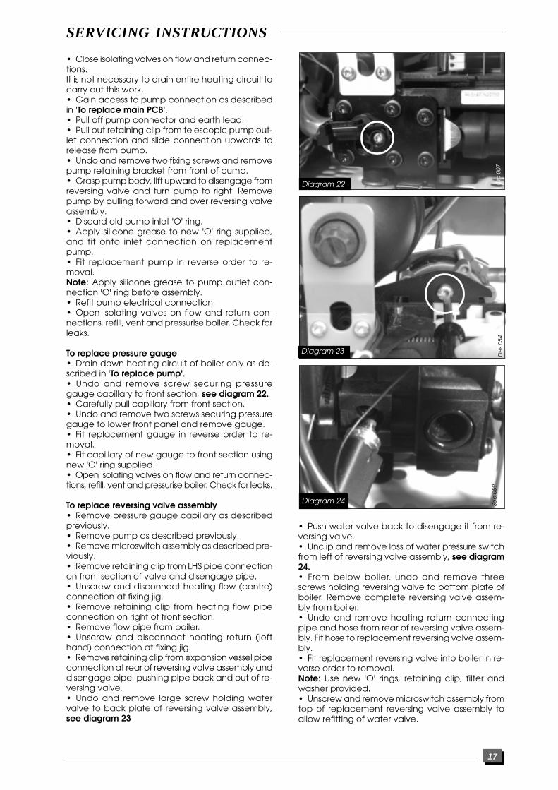
To replace pressure gauge• Drain down heating circuit of boiler only as de-scribed in 'To replace pump'.• Undo and remove screw securing pressuregauge capillary to front section, see diagram 22.• Carefully pull capillary from front section.• Undo and remove two screws securing pressuregauge to lower front panel and remove gauge.• Fit replacement gauge in reverse order to re-moval.• Fit capillary of new gauge to front section usingnew 'O' ring supplied.• Open isolating valves on flow and return connec-tions, refill, vent and pressurise boiler. Check for leaks.
To replace reversing valve assembly• Remove pressure gauge capillary as describedpreviously.• Remove pump as described previously.• Remove microswitch assembly as described pre-viously.• Remove retaining clip from LHS pipe connectionon front section of valve and disengage pipe.• Unscrew and disconnect heating flow (centre)connection at fixing jig.• Remove retaining clip from heating flow pipeconnection on right of front section.• Remove flow pipe from boiler.• Unscrew and disconnect heating return (lefthand) connection at fixing jig.• Remove retaining clip from expansion vessel pipeconnection at rear of reversing valve assembly anddisengage pipe, pushing pipe back and out of re-versing valve.• Undo and remove large screw holding watervalve to back plate of reversing valve assembly,see diagram 23
• Push water valve back to disengage it from re-versing valve.• Unclip and remove loss of water pressure switchfrom left of reversing valve assembly, see diagram24.• From below boiler, undo and remove threescrews holding reversing valve to bottom plate ofboiler. Remove complete reversing valve assem-bly from boiler.• Undo and remove heating return connectingpipe and hose from rear of reversing valve assem-bly. Fit hose to replacement reversing valve assem-bly.• Fit replacement reversing valve into boiler in re-verse order to removal.Note: Use new 'O' rings, retaining clip, filter andwasher provided.• Unscrew and remove microswitch assembly fromtop of replacement reversing valve assembly toallow refitting of water valve.
Diagram 22 Cla
007
Diagram 23
De
s 05
4
SERVICING INSTRUCTIONS
Diagram 24 Sec
059

18
Note: fit expansion vessel pipe and loss of waterswitch to reversing valve assembly before pump,to ensure that it is correctly located. Apply siliconegrease to all 'O' rings and hoses prior to assembly.• Open isolating valves on flow and return con-nections, refill, vent and pressurise boiler. Check forleaks.
To replace reversing valve front section• Remove pressure gauge capillary as describedpreviously.• Remove pipe connections from either side ofreversing valve front section, refer to previous sec-tion.• Move short selector lever on front of valve to lefthand position.• From below boiler, undo and remove single screwholding reversing valve front plate to bottom plateof boiler.• Undo and remove six screws holding front sec-tion to rear section of reversing valve, see diagram 25.• Remove front plate complete with pump bracketand then front section from reversing valve, alongwith rubber sealing gasket.• Assemble bypass valve provided and fit into holein underside of replacement front section. Fit 'U'shaped retaining clip.Note: Use bypass valve fitted to original front sec-tion for guidance.• Fit replacement front section, with gasket, to rearsection.• Locate front plate and replace six fixing screws.Take care to evenly tighten screws ensuring theyare not cross threaded.• Refit pipe connections to either side of front sec-tion using new 'O' rings provided. Apply siliconegrease to 'O' rings before fitting.• Refit pressure gauge capillary in reverse order toremoval.• Ensure short selector lever on front of valve is setto right hand position.• Open isolating valves on flow and return con-nections, refill, vent and pressurise boiler. Check forleaks.
To replace loss of water switch• Drain down heating circuit of boiler only as de-scribed in 'To replace pump'.Note: It is not necessary to drain entire heating cir-cuit to carry out this work.• Pinch plastic cover to release retaing clips andremove cover from switch. Pull plug lead fromswitch terminals.• Remove clip holding switch into left side of re-versing valve assembly.• Pull switch out of reversing valve assembly, seediagram 24.• Fit replacement switch in reverse order to re-moval, using new 'O' ring provided and aplying sili-cone grease to 'O' ring before fitting.• Reconnect plug to switch terminals.• Open isolating valves on flow and return con-nections, refill, vent and pressurise boiler. Check forleaks.
Diagram 25 Cla
007
To replace water valve or diaphragm• Drain down hot water circuit of boiler only asdescribed in 'Routine Cleaning and Inspection'.• Remove microswitch assembly as described pre-viously.• Remove clip holding connecting pipe in rear ofwater valve. From below boiler, grip clip with longnosed pliers and pull down.• Using long nosed pliers, slide pipe away fromwater valve into brass cold water inlet connection.• Remove clip holding pipe to heat exchanger inrear of water valve. From front of boiler, gripclip withlong nosed pliers and pull upwards.• Unscrew and remove large screw holding watervalve to back plate of reversing valve assembly,see diagram 23.• Disengage water valve from reversing valve andremove from boiler.Note: When disengaging water valve from heatexchanger pipe, check that non-return valve is notheld on end of pipe. If so, carefully separate pipefrom valve to ensure that small spring and plungerdo not fly out and are lost.• To replace diaphragm, undo five screws andseparate main components of water valve.• If white diaphragm cover is to be replaced, sepa-rate original from water valve end casting and fitreplacement cover.• Fit replacement diaphragm , making sure thatmetal disc FACES diaphragm cover and beadededge of diaphragm is correctly fitted in correspond-ing groove in both cover and plastic housing, seediagram 26.• Reassemble water valve, evenly tightening fivescrews.• Fit water valve actuating pin into hole in dia-phragm cover, through nose end of valve and andpush in until flush, or slightly below, nose end ofvalve.Note: Apply silicone grease to pin before fitting.• Refit water valve to boiler, locating nose end intorear of reversing valve assembly, 'springing' heatexchanger pipe to gain clearance as necessary.Fit large water valve retaining screw but do nottighten fully at this stage.• Apply silicone grease to 'O' ring and fit onto endof heat exchanger pipe. Fit pipe into water valveby pulling it forward. Make sure that 'O' ring is cor-rectly located.• Whilst holding pipe in rear of water valve, fit re-taining clip. This should easily clip over pipe and
SERVICING INSTRUCTIONS

19
should NOT have to be forced. If resistance is ex-perienced, either pipe is not correctly fitted in rearof water valve or clip is not being fitted properlythrough slot between back plate and plastic hous-ing of water valve. When clip is fitted, check con-nection by pushing pipe back away from watervalve.• Refit telescopic connecting pipe to inlet of wa-ter valve after applying silicone grease to 'O' ring.Fit retaining clip into groove on connecting pipe,through slot between back plate and water valveplastic housing. Check connection by pulling pipe.Make sure that clip is not loose and likely to fall outat a later date. If in doubt, fit a new clip.• Replace microswitch assembly.• Open isolating valve on cold water inlet connec-tion and check for leaks.
To replace gas valve• Ensure gas supply is off.• Disconnect two black electrical leads from gasvalve modulating coil.• Disconnect two white and one red lead from gasvalve main solenoid.• Pull off clear plastic tube from gas valve to sealedchamber tapping point.• Unscrew main gas supply pipe nut on top of gasvalve, releasing spark ignition unit bracket, see dia-gram 27.• From below boiler, unscrew gas valve connec-tion between gas valve and isolating cock.• Unscrew and remove two screws securing gasvalve to bottom plate of boiler.• Remove gas valve from boiler.• Refit replacement gas valve in reverse order toremoval.Note: Use new 'O' ring provided between gas valveand burner supply pipe.• Refit electrical connections to replacement gasvalve as follows:
- BLACK leads to modulating coil.- WHITE leads to EV1 and EV2 terminals of main
solenoid- RED lead to COM terminal of main solenoid.
To replace modulating coil• Ensure gas supply is off.• Disconnect two black electrical leads from gasvalve modulating coil.• Unscrew and remove two screws holding modu-lating coil to gas valve and remove coil from gasvalve.• Fit replacement modulating coil in recerse orderto removal.• Reconnect electrical leads to replacement coil.Note: All boilers are tested and factory set duringmanufacture. Should it be necessary to reset a gasvalve, for example after replacement, refer to 'Set-tings'.To replace safety valve• Drain down heating circuit of boiler only usingdrain point on front of non-return valve (located tothe right of reversing valve.• Disconnect safety valve discharge pipe fromsafety valve.
Diagram 26 De
s 05
8
Diagram 27 Me
c 1
17
• Pull out clips securing safety valve to non-returnvalve.• Remove safety valve from boiler• Fit replacement safety valve in reverse order toremoval.Note: Apply silicone grease to 'O' ring before fittingsafety valve into non-return valve body.• Refill boiler, vent and pressurise as described pre-viously.
To replace heat exchanger• Drain down both heating and hot water circuitsof boiler only as described previously.Note: It is not necessary to drain entire heating sys-tem to carry out this work.• Remove combustion chamber cover as de-scribed in 'Routine Cleaning and Inspection'.• Remove two clips from heating connections toleft side of heat exchanger.• Remove clip holding pump outlet connectioninto pump and slide connection up pump outletpipe. Pull complete pipe down to disengage fromheat exchanger.• Remove retaining clip from LHS pipe connectionon front section of valve and disengage pipe.• Disengage pipe downwards from heat ex-changer.• Unscrew and disconnect two hot water connec-tions to right side of heat exchanger.• Grasp both sides of heat exchanger and slideforwards and out of boiler.• Fit replacement heat exchanger in reverse or-der to removal.Note: Use new sealing washers and 'O' rings pro-vided.• Open isolating valves on flow and return con-nections, refill, vent and pressurise boiler. Check forleaks.
SERVICING INSTRUCTIONS

20
To replace expansion vessel
1 Boiler in placeNote: The expansion vessel can be replaced withthe boiler in place provided that there is a mini-mum clearance of 400mm on one side of the boilerand that no vertical pipework passes betweenboiler and wall on that side.• Drain down the heating circuit of the boiler onlyas described in 'To replace pump'.Note: It is not necessary to drain entire heating sys-tem to carry out this work.• Remove pump from boiler as described previ-ously.• Unscrew pipe connection nut from expansionvessel and disengage pipe from connection. Keepsealing washer.• Whilst supporting weight of vessel, push bottomof vessel away from boiler, disengaging threadedconnection from hole in rear of boiler. Allow vesselto drop out of its two upper retaining brackets.• Remove vessel to side of boiler.• Fit replacement expansion vessel in reverse or-der to removal ensuring that sealing washer is fit-ted to vessel pipe connection.• Check that vessel charge pressure is 1bar. Cor-rect if necessary.• Open isolating valves on flow and return con-nections, refill, vent and pressurise boiler. Check forleaks.
2 Boiler removed from wall• Drain down the heating circuit of the boiler onlyas described in 'To replace pump'.Note: It is not necessary to drain entire heating sys-tem to carry out this work.• Ensure that gas and electrical supplies to boilerare turned off.• Disconnect flue from either rear or top of boileras applicable.• Disconnect external controls connections, if ap-plicable.• Unscrew and disconnect five connections be-tween fixing jig and boiler.• Disengage pipe connections. Lift boiler off hang-ing bracket and place on a convenient workingsurface.• Remove expansion vessel from boiler as de-scribed in previous section.• Fit replacement vessel in reverse order to removaland check charge pressure.• Replace boiler on wall, tighten all connections,gas connection first, ensuring that all sealing wash-ers, filters and the cold water flow regulator are fit-ted before tightening.• Reconnect flue system.• Open isolating valves on flow and return con-nections, refill, vent and pressurise boiler. Check forleaks.• Reconnect external controls connections, if ap-plicable.• Reconnect gas and electrical supplies to boiler.• Check for gas soundness.
To replace boiler thermistor• Locate boiler thermistor on heating flow pipe on
left hand side of boiler, see diagram 28.• Unclip thermistor from pipe.• Pull off electrical connections from thermistor.• Fit replacement thermistor in reverse order to re-moval.Note: No heat sink compound is required. The po-larity of the connections is not important.
To replace overheat thermostat• Locate the overheat thermostat on the righthand side of the heat exchanger.• Pull off the electrical connections from the ther-mostat.• Unscrew and remove two screws holding ther-mostat to heat exchanger.• Fit replacement thermostat in reverse order toremoval, using heat sink compound on the con-tact surface of thermostat.• Refit electrical leads, the polarity is not impor-tant.
To replace combustion chamber insulationFront section• Remove combustion chamber from boiler asdescribed in 'Routine Cleaning and Inspection'.• Slide side panels out of combustion chambersides.• Lift front insulation panel free from retaining lugsand away from cover.• Fit replacement panels in reverse order to re-moval.
Rear panel• Remove burner from boiler as described in 'Rou-tine Cleaning and Inspection'.• Remove clip from base of insulation panel.• Pull bottom edge of insulation panel forward,downward and out from behind heat exchanger.• Fit replacement panel in reverse order to re-moval.• Replace burner into boiler in reverse order to re-moval.
To replace ignition electrode• Remove combustion chamber from boiler asdescribed in 'Routine Cleaning and Inspection'.• Pull off ignition leads from ignition electrode.• Unscrew and remove two screws holding igni-tion electrode onto burner.• Fit replacement ignition electrode in reverse or-der to removal.• Refit ignition leads, the polarity is not important.
Diagram 28
Sec
060
SERVICING INSTRUCTIONS
21
To replace flame sense electrode• Remove combustion chamber from boiler asdescribed in 'Routine Cleaning and Inspection'.• Pull off lead from flame sense electrode.• Unscrew and remove screw holding earth leadto flame sense electrode.• Unscrew and remove screw holding flame senseelectrode onto burner.• Fit replacement flame sense electrode in reverseorder to removal.• Refit lead.To replace burner• Pull off ignition and flame sense leads from elec-trodes.• Remove burner from boiler as described in 'Rou-tine Cleaning and Inspection'.• Remove ignition and flame sense electrodes asdescribed in previous sections.• Unscrew and remove two screws holding burnerinjector bar to burner and remove injector bar.• Asemble replacement burner, supplied in parts,as follows:• Fit burner injectors to injector bar and tighten.• Assemble burner elements (14) into front and rearburner supports with securing pins and rods, usingoriginal burner for guidance.• Fit burner injector bar to burner.• Fit ignition and flame sense electrodes to burner.• Fit replacement burner to boiler in reverse orderto removal.
SERVICING INSTRUCTIONS
• Reconnect ignition and flame sense leads toelectrodes. Reconnect earth lead to flame senseelectrode. The polarity of the ignition leads is notimportant.
To replace burner injectors• Remove burner as described previously.• Remove ignition and flame sense electrodes asdescribed in previous sections.• Unscrew and remove two screws holding burnerinjector bar to burner and remove injector bar.• Unscrew and remove burner injectors from burnerbar.• Fit replacement injectors to injector bar andtighten.Note: make sure that injector size, marked on eachinjector, is the same as that given in 'Technical Data'.• Reassemble burner and replace into boiler inreverse order to removal.
To replace timeclock• Gain access to rear of lower control panel asdescribed in 'Routine Cleaning and Inspection'.• Unscrew and remove two screws holdingtimeclock to lower control panel.• Remove PCB cover.• Remove timeclock plug from connection CN7on main PCB.• Fit replacement timeclock in reverse order to re-moval.
22
SCHEMATIC WIRING DIAGRAM
Diagram 29 Sch
242
N L
P
Ex
EV
3
EV
1
EV
2
TR
A
6.14
6.13
6.15
6.11
CT
N
SW
3
TA K
5
K4
Pr
FL
Ra
FA
Al
6.12
6.9
13.2
13.3
13.1
13.4
14.1
14.2
14.7
14.3
14.4
14.5
14.6
14.8
14.9
6.8
6.6
6.4
6.2
6.3
2.2
2.1
9.1
9.2
8.4
8.3
8.2
8.1
12.1
12.2
P
CN 7
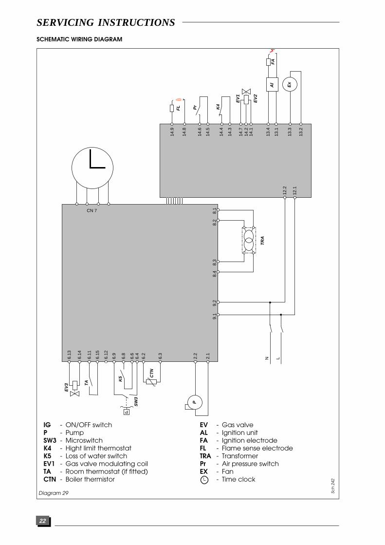
IG - ON/OFF switchP - PumpSW3 - MicroswitchK4 - Hight limit thermostatK5 - Loss of water switchEV1 - Gas valve modulating coilTA - Room thermostat (if fitted)CTN - Boiler thermistor
EV - Gas valveAL - Ignition unitFA - Ignition electrodeFL - Flame sense electrodeTRA - TransformerPr - Air pressure switchEX - Fan
- Time clock
SERVICING INSTRUCTIONS

23
Prior to fault finding, check :Inlet gas pressure = 20 mbarElectrical supply = 240 V - 50 HzCentral heating system is pressurised at 1 - 1,5 bar.Overheat thermostat on RHS of heat exchanger hasnot tripped reset if necessary.
Carry out electrical system checks i.e. earth continu-ity, resistance to earth, short circuit and polarity witha suitable meter.Note : these must be repeated after any servicing orfault finding. Ensure that all external controls are cor-rectly wired and calling for heat.
The fault finding charts will enable the majority of faultsto be diagnosed. To use the charts effectively, it is
necessary to determine exactly which aspects of theboiler are working correctly and which are not.For example:If the domestic hot water works but the heatingdoesn’t, refer to chart No. 1.If heating works correctly but the hot water doesn’t,refer to chart No. 2.
IMPORTANT: Always adopt a logical, step by step pro-cedure starting at the beginning of the appropriatefault finding chart.
WARNING. Always isolate the boiler from the electri-cal supply before carrying out any electrical replace-ment work.Always check for gas soundness after any servicework.
NO CENTRAL HEATING
CHART 1
Replace main pcb
Replace clock
Refer to chart n°3
Refer to chart n°4Does fan run ?
Does pump run ?
Internal control(clock)
External controls(if fitted)
Remove leaos from boilerthermistor. Check its
resistance according tothermistor value table.
Is thermistor ok ?
Short out external controlsconnection on top ofreversing valve. Does
burner fire ?
Rectify wiringoperation faults on
external controls
Is wiring betweenclock and pcb
connection cn7 ok ?Replace thermistor
Is clock calling forheat ?
Is therecontinuity acrossterminals 3 and 4
of clock ?
Replacemain pcb
Turn ch temp. control tomax. does burner fire ?
NO
NO
NO
NO
NONO
YES
NO
YES
YES
YES
YES
YES
YES
Is short selector lever onfront of reversing valve in
right hand position ?
Does burner fire whena hot tap is opened ?
Refer to chart n°2
YES
YES
YES
SERVICING INSTRUCTIONS
FAULT FINDING
YES
Move to rightNO
24 110664A 06/98
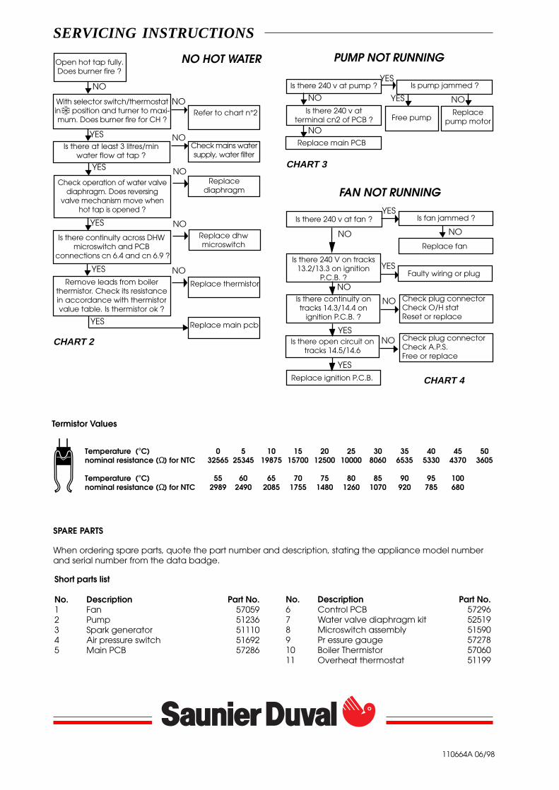
SPARE PARTS
When ordering spare parts, quote the part number and description, stating the appliance model numberand serial number from the data badge.
Short parts list
No. Description Part No.1 Fan 570592 Pump 512363 Spark generator 511104 Air pressure switch 516925 Main PCB 57286
No. Description Part No.6 Control PCB 572967 Water valve diaphragm kit 525198 Microswitch assembly 515909 Pr essure gauge 5727810 Boiler Thermistor 5706011 Overheat thermostat 51199
NO HOT WATER
Replace main pcb
Refer to chart n°2
Check mains watersupply, water filter
Is there at least 3 litres/minwater flow at tap ?
Remove leads from boilerthermistor. Check its resistancein accordance with thermistorvalue table. Is thermistor ok ?
Check operation of water valvediaphragm. Does reversing
valve mechanism move whenhot tap is opened ?
Replacediaphragm
Replace thermistor
Open hot tap fully.Does burner fire ?
YES
NO
NO
YES
YES
NO
With selector switch/thermostatin position and turner to maxi-mum. Does burner fire for CH ?
Is there continuity across DHWmicroswitch and PCB
connections cn 6.4 and cn 6.9 ?
YES
Replace dhwmicroswitch
Is there 240 v at pump ?YES
Is there 240 v atterminal cn2 of PCB ?
Is there 240 v at fan ?
NO
YES
CHART 2
NO
NO
NO
CHART 3
PUMP NOT RUNNING
FAN NOT RUNNING
Replace main PCB
YES
CHART 4
NO
NO
Is pump jammed ?
Replacepump motor
NO
Free pump
Is fan jammed ?
Replace fan
NO
Temperature (°C) 0 5 10 15 20 25 30 35 40 45 50nominal resistance (Ω) for NTC 32565 25345 19875 15700 12500 10000 8060 6535 5330 4370 3605
Temperature (°C) 55 60 65 70 75 80 85 90 95 100nominal resistance (Ω) for NTC 2989 2490 2085 1755 1480 1260 1070 920 785 680
Termistor Values
YES
SERVICING INSTRUCTIONS
Is there 240 V on tracks13.2/13.3 on ignition
P.C.B. ?
YESFaulty wiring or plug
Is there continuity ontracks 14.3/14.4 on
ignition P.C.B. ?
Check plug connectorCheck O/H statReset or replace
Is there open circuit ontracks 14.5/14.6
Replace ignition P.C.B.
NO
YES
YES
NO
Check plug connectorCheck A.P.S.Free or replace
NO