combined overvoltage and reu 523 undervoltage relay · 2018-05-10 · combined overvoltage and...
TRANSCRIPT

Combined Overvoltage and Undervoltage Relay
Product Guide
REU 523

Combined Overvoltage and Undervoltage Relay
REU 5231MRS751123-MBG
Issued: 15.06.1999Status: Updated Version: D/08.05.2006Data subject to change without notice
3
Features • Single or three-phase use
• High-set overvoltage stage with definite-time or inverse definite minimum time (IDMT) characteristic
• Low-set overvoltage stage with definite-time or IDMT characteristic
• High-set undervoltage stage with definite-time or IDMT characteristic
• Low-set undervoltage stage with definite-time or IDMT characteristic
• Positive-phase-sequence protection
• Ajustable drop-off/pick-up ratio for the low-set stages
• Circuit-breaker failure protection (CBFP)
• Disturbance recorder
- recording time up to 12 seconds
- triggering by a start or a trip signal from a protection stage and/or by a binary input signal
- records three analogue channels and eight digital channels
- adjustable sampling rate
• Non-volatile memory for
- up to 60 event codes
- setting values
- disturbance recorder data
- recorded data of the five last events with time stamp
- number of starts for each stage
- alarm indication messages and LEDs showing the status at the moment of power failure
• Galvanically isolated binary input with a wide input voltage range
• All settings can be modified with a personal computer
• HMI with an alphanumeric LCD and manoeuvring buttons
• IEC 60870-5-103 and SPA bus communi-cation protocols
• Two normally open power output contacts
• Two change-over signal output contacts
• Output contact functions freely config-urable for desired operation
• Optical PC-connector for two-way data communication (front)
• RS-485 connector (rear) for system com-munication
• Continuous self-supervision of electronics and software. At an internal relay fault (IRF), all protection stages and outputs are blocked.
• User-selectable rated frequency 50/60 Hz
• User-selectable password protection for the HMI
• User-selectable nominal voltage 100/110/115/120 V
• Display of primary voltage values
• Demand values
• Multi-language support

Combined Overvoltage and Undervoltage Relay
REU 5231MRS751123-MBG
Application The over and undervoltage relay REU 523 is a secondary relay which is connected to the voltage transformers of the object to be pro-tected. The over and the undervoltage unit continuously measure the fundamental wave of the phase-to-phase voltages of the object. On detection of a fault, the relay will start, trip the circuit breaker, provide alarms, record fault data, etc., in accordance with the appli-cation and the configured relay functions.
The overvoltage unit includes low-set stage U> and high-set stage U>> and the undervolt-age unit low-set stage U< and high-set stage U<<. The high-set undervoltage stage can
alternatively be set to evaluate the positive-phase-sequence voltage. In addition, the high-set undervoltage stage can be configured to evaluate only one instead of three phase-to-phase voltages.
The protection functions are independent of each other and have their own setting groups and data recordings. The over and undervolt-age functions use conventional voltage trans-former measurement.
An output contact matrix allows start or trip signals from the protection stages to be routed to the desired output contact.
Design The relay includes a high-set and low-set overvoltage unit, a high-set and low-set und-ervoltage unit and a circuit-breaker failure protection unit. Further, the relay includes an HMI module, a self-supervision system and a disturbance recorder.
Overvoltage unitWhen the voltage values exceed the set start value of low-set stage U>, the overvoltage unit will start to deliver a start signal after a ~60 ms’ start time. When the set operate time at definite-time characteristic or the calcu-lated operate time at inverse definite mini-mum time (IDMT) characteristic elapses, the overvoltage unit will deliver a trip signal.
When the voltage values exceed the set start value of high-set stage U>>, the overvoltage unit will start to deliver a start signal after a ~50 ms’ start time. When the set operate time at definite-time characteristic or the calcu-lated operate time at IDMT characteristic elapses, the overvoltage unit will deliver a trip signal.
The low-set and the high-set stage of the overvoltage unit can be given either a defi-nite-time or an IDMT characteristic. At IDMT characteristic, two time/voltage curve groups, A and B, are available.
It is possible to block the tripping of an over-voltage stage by applying an external binary input signal to the relay.
The high-set stage can be set out of operation. This state will be indicated by dashes on the LCD and by “999” when the set start value is read via serial communication.
Undervoltage unitWhen the voltage values fall below the set start value of low-set stage U<, the undervolt-age unit will start to deliver a start signal after a ~ 80 ms’ start time. When the set operate time at definite-time characteristic or the cal-culated operate time at IDMT characteristic elapses, the undervoltage unit will deliver a trip signal.
The high-set undervoltage stage, U<<, can be set to start and trip either based on conven-tional undervoltage measurement or on the calculated positive-phase-sequence voltage, U1s. Selecting either of these two will auto-matically deseclect the other.
When the conventional protection mode has been selected and the voltage values fall below the set start value of the high-set stage, the undervoltage unit will start to deliver a start signal after a ~50 ms’ start time.
When the positive-phase-sequence protec-tion mode has been selected and the calcu-lated positive-phase-sequence voltage value, U1s, falls below the set start value of the high-set stage, the undervoltage unit will start to deliver a start signal after a ~50 ms’ start time. When the set operate time at definite-time characteristic or the calculated operate time at IDMT characteristic elapses, the und-ervoltage unit will deliver a trip signal.
The low-set and the high-set stage of the und-ervoltage unit can be given either a definite-time or an IDMT characteristic. At IDMT characteristic, one time/voltage curve group, C, is available.
The start and the tripping of an undervoltage stage can be set to be internally blocked when the measured value falls below 0.2 x Un. In
4

Combined Overvoltage and Undervoltage Relay
REU 5231MRS751123-MBG
5
addition, the tripping of stage U< can be set to be blocked by the start of stage U<<. The tripping of an undervoltage stage can also be blocked by applying an external binary input signal to the relay.
The high-set stage can be set out of operation. This state will be indicated by dashes on the LCD and by “999” when the set start value is read via serial communication.
Circuit breaker failure protection (CBFP) unitThe CBFP unit will generate a trip signal via power output 2 (PO2) if the fault has not been cleared on expiration of the set operate time 0.10 s...1.00 s.
Normally, the CBFP unit controls the up-stream circuit breaker. It can also be used for tripping via redundant trip circuits of the same circuit breaker. The CBFP unit is acti-vated with a soft-ware switch.
Disturbance recorderThe REU 523 includes an internal distur-bance recorder which records the momentary measured values, or the RMS curves of the measured signals, and eight digital signals: the external binary input signal and the states of the internal protection stages. The distur-bance recorder can be set to be triggered by a start or a trip signal from any protection stage and/or by an external binary input signal, and either on the falling or rising triggering edge. The ratio of the pre- and post-triggering of the recording can be set.
The recording length varies according to the selected sampling frequency. The RMS curve is recorded by selecting the sampling fre-quency to be the same as the nominal fre-quency of the relay. See the table below for details:
Nominal frequency Hz
Sampling frequency Hz
Recording length s
50 800 0.6050 400 1.2050 50 9.60
60 960 1.0060 480 2.0060 60 16.00
HMI moduleThe HMI of the REU 523 is equipped with six push-buttons and an alphanumeric 2 x 16 characters’ LCD. The push-buttons are used for navigating in the menu structure and for adjusting set values.
An HMI password can be set to protect all user-changeable values from being changed by an unauthorised person.
The REU 523 offers you multi-language sup-port. The following languages are available for the HMI menu: English, German, French, Spanish, Italian, Swedish and Finnish.
Self-supervision (IRF)The REU 523 is provided with an extensive self-supervision system which continuously supervises the software and the electronics of the relay. It manages run-time fault situations and informs the user about an existing fault via a LED on the HMI and a text message on the LCD.
Communication capabilitiesThe REU 523 can be connected to a substa-tion automation or monitoring system using either the SPA bus communication protocol or the IEC 60870-5-103 remote communica-tion protocol. Both protocols are supported in the same device.
The SPA bus communication protocol is an asynchronous serial communication protocol (1 start bit, 7 data bits + even parity, and 1 stop bit) with a selectable data transfer rate (default 9.6 kbps). It is a master/slave proto-col supporting one master device and several slave devices. The SPA bus protocol can be used to transfer data, e.g. measured currents, registered values, events, and relay settings, between the master and the slave device.
The REU 523 supports the IEC 60870-5-103 remote communication protocol in the unbal-anced transmission mode with a data transfer rate of 9.6 kbps. The IEC 60870-5-103 proto-col is used to transfer mesurand and status data from the slave to the master. Disturbance recorder data, however, cannot be transferred using this protocol.
The REU 523 is provided with two serial communication ports, one on the rear panel and the other on the front panel.
Combined Overvoltage and Undervoltage Relay
REU 5231MRS751123-MBG
The REU 523 is interfaced with a fibre-optic bus by means of the bus connection module RER 103 via the D9S-type RS-485 connector on the rear panel of the device. The RER 103 enables the use of either the SPA bus or the IEC 60870-5-103 communication protocol. The use of the IEC 60870-5-103 protocol normally requires the fibre-optic star coupler RER 125.
The optical PC-connector on the front panel is used to connect the relay to the CAP 501/ 505 setting and configuration tools. The front interface uses the SPA bus protocol. The opti-cal PC-connector galvanically isolates the PC from the relay. Since this connector is stan-dardized for ABB relay products, only one connecting cable (ABB art. No 1MKC-950001-1) will be required.
The REU 523 can also be connected to the Lon bus using a LON-SPA Gateway.
Auxiliary Supply VoltageThe REU 523 requires a secured auxiliary voltage supply to operate. The internal power supply of the relay forms the voltages requir-ed by the relay electronics. The power supply is a galvanically isolated (flyback-type) DC/DC converter. When the auxiliary volt-age is connected, the READY indicator LED on the front panel will be on.
The primary side of the power supply is pro-tected with a fuse located on the PCB of the relay. The fuse size is 3.15 A (slow).
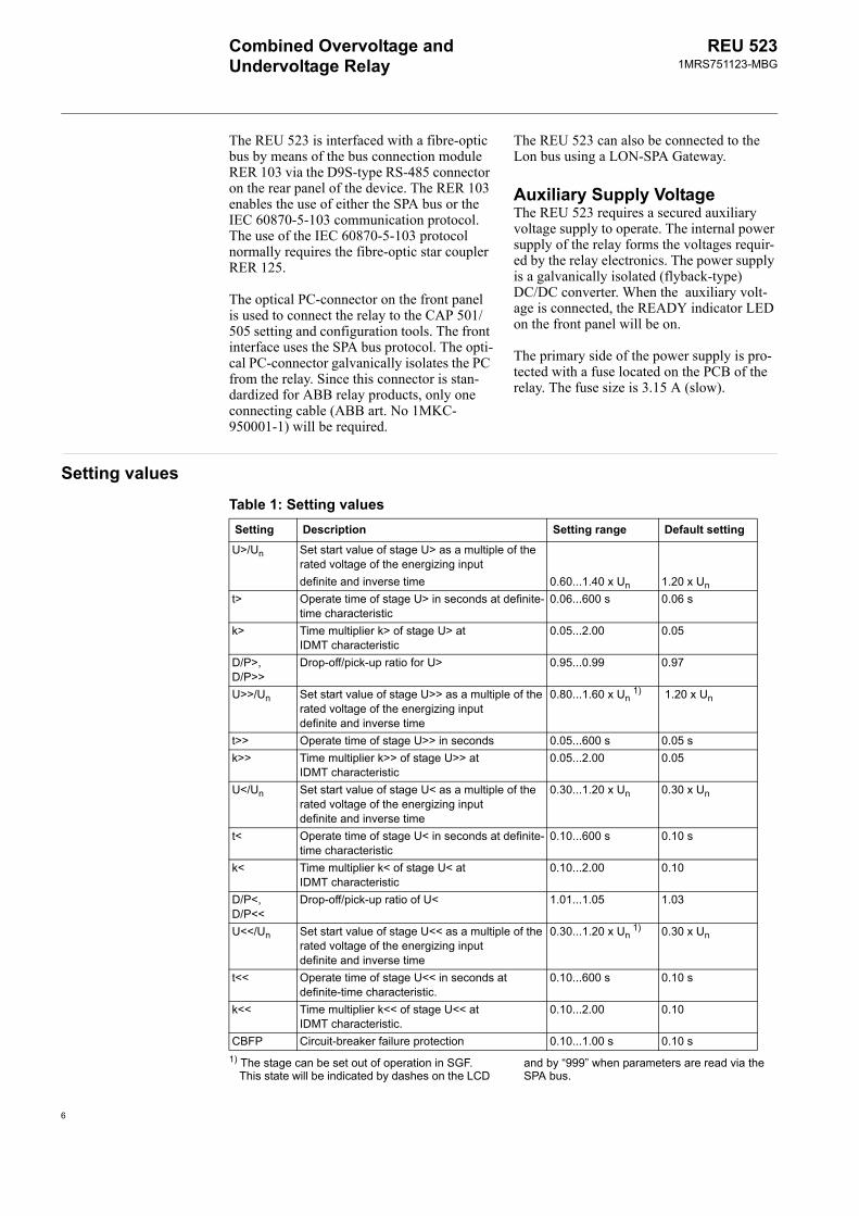
Setting values
Table 1: Setting valuesSetting Description Setting range Default setting
U>/Un Set start value of stage U> as a multiple of the rated voltage of the energizing input definite and inverse time 0.60...1.40 x Un 1.20 x Un
t> Operate time of stage U> in seconds at definite-time characteristic
0.06...600 s 0.06 s
k> Time multiplier k> of stage U> at IDMT characteristic
0.05...2.00 0.05
D/P>, D/P>>
Drop-off/pick-up ratio for U> 0.95...0.99 0.97
U>>/Un Set start value of stage U>> as a multiple of the rated voltage of the energizing inputdefinite and inverse time
0.80...1.60 x Un 1) 1.20 x Un
t>> Operate time of stage U>> in seconds 0.05...600 s 0.05 sk>> Time multiplier k>> of stage U>> at
IDMT characteristic0.05...2.00 0.05
U</Un Set start value of stage U< as a multiple of the rated voltage of the energizing inputdefinite and inverse time
0.30...1.20 x Un 0.30 x Un
t< Operate time of stage U< in seconds at definite-time characteristic
0.10...600 s 0.10 s
k< Time multiplier k< of stage U< at IDMT characteristic
0.10...2.00 0.10
D/P<, D/P<<
Drop-off/pick-up ratio of U< 1.01...1.05 1.03
U<</Un Set start value of stage U<< as a multiple of the rated voltage of the energizing input definite and inverse time
0.30...1.20 x Un 1) 0.30 x Un
t<< Operate time of stage U<< in seconds at definite-time characteristic.
0.10...600 s 0.10 s
k<< Time multiplier k<< of stage U<< at IDMT characteristic.
0.10...2.00 0.10
CBFP Circuit-breaker failure protection 0.10...1.00 s 0.10 s1) The stage can be set out of operation in SGF.
This state will be indicated by dashes on the LCD and by “999” when parameters are read via the SPA bus.
6

Combined Overvoltage and Undervoltage Relay
REU 5231MRS751123-MBG
7
Technical dataTable 2: Energizing inputsRated frequency 50/60 Hz ±5 HzRated voltage, Un 100/110/115/120 VMaximum input voltage- continuously 2 x Un- for 10 s 3 x UnPower consumption at Un < 0.1 VA (typical 0.03 VA)Thermal withstand capability- continuously 2 x Un- for 10 s 3 x UnInput impedance > 4.7 MΩ
Table 3: Measuring rangeMeasured voltages on phases U12, U23 and U31 as multiples of the rated voltages of the energizing inputs
0…2 x Un
Measuring accuracy (fn ±5 Hz) at 0.20...2.00 x Un ±1.5%
Table 4: Binary inputOperating range 18…265 V dcRated voltage Ur = 24/48/60/110/220 V dcCurrent drain ~ 2…25 mAPower consumption < 0.8 W
Table 5: Power outputs (PO1 and PO2)Rated voltage 250 V ac/dcContinuous carry 5 AMake and carry for 3.0 s 15 AMake and carry for 0.5 s 30 ABreaking capacity when the control circuit time-constant L/R < 40 ms, at 48/110/220 V dc
5 A/3 A/1 A
Minimum contact load 100 mA at 24 V ac/dc
Table 6: Signal outputs (SO1, SO2) and self-supervision (IRF) outputRated voltage 250 V ac/dcContinuous carry 5 AMake and carry for 3.0 s 8 AMake and carry for 0.5 s 10 ABreaking capacity when the control circuit time-constant L/R < 40 ms, at 48/110/220 V dc
1 A/0.25 A/0.15 A
Minimum contact load 100 mA at 24 V ac/dc

Combined Overvoltage and Undervoltage Relay
REU 5231MRS751123-MBG
Table 7: Data communicationRear interface, connector X2.2 RS-485 connection for the fibre-optic interface
module RER 103SPA bus or IEC 60870-5-103 protocol4.8 or 9.6 kbps
Front interface Optical RS-232 connection for opto-cable 1MKC 950001-1SPA bus protocol 4.8 or 9.6 kbps
Table 8: Auxiliary supply voltageUaux rated Ur =110/120/220/240 V ac
Ur =48/60/110/125/220 V dcUaux variation 80…265 V ac
38…265 V dcRelay power start-up time, typical 300 msBurden of auxiliary supply under quiescent/operating condition
~ 4 W/~ 10 W
Ripple in the dc auxiliary voltage Max 12% of the dc valueInterruption time in the auxiliary dc voltage without resetting the relay
< 30 ms at 48 V dc< 100 ms at 110 V dc< 500 ms at 220 V dc
Table 9: Enclosure classFront side IP 54 (flush-mounted)Rear side, connection terminals IP20Note! A rear protective cover (accessory part) can be used to protect and shield the rear of the case.
Table 10: DimensionsWidth Frame 111.4 mm, box 94.0 mmHeight Frame 265.9 mm (6U), box 249.8 mmDepth 235 mm (245.1 mm with a protective rear cover,
available as an option)Enclosure size 1/4 (x 19”)Weight of the relay ~3.2 kg
8

Combined Overvoltage and Undervoltage Relay
REU 5231MRS751123-MBG
Table 11: Environmental testsSpecified service temperature range -10...+55 °CStorage temperature tests -40...+70 °C according to the IEC 60068-2-48Dry heat test According to the IEC 60068-2-2Dry cold test According to the IEC 60068-2-1 Damp heat test, cyclic According to the IEC 60068-2-30
9
Table 12: Standard testsInsulation testsDielectric tests According to the IEC 60255-5Test voltage 2 kV, 50 Hz, 1 minImpulse voltage test According to the IEC 60255-5Test voltage 5 kV, unipolar impulses, waveform 1.2/50 µs, source
energy 0.5 JInsulation resistance measurements According to the IEC 60255-5Isolation resistance > 100 MΩ, 500 V dcMechanical testsVibration tests (sinusoidal) According to the IEC 60255-21-1, class IShock and bump test According to the IEC 60255-21-2, class ISeismic test According to the IEC 60255-21-3, class 2
Table 13: Electromagnetic compatibility testsEMC immunity test level requirements consider the demands in the generic standard EN 50082-21 MHz burst disturbance test, class III According to the IEC 60255-22-1- common mode 2.5 kV- differential mode 1.0 kVElectrostatic discharge test, class III According to the IEC 61000-4-2 and
IEC 60255-22-2- for contact discharge 6 kV- for air discharge 8 kVRadio frequency interference tests- conducted, common mode According to the IEC 61000-4-6,
IEC 60255-22-6 (2000) 10 V (rms), f = 150 kHz…80 MHz
- radiated, amplitude-modulated According to the IEC 61000-4-3 IEC 60255-22-3 (2000) 10 V/m (rms), f = 80…1000 MHz
- radiated, pulse-modulated According to the ENV 50204 IEC 60255-22-3 (2000)10 V/m, f = 900 MHz
- radiated, test with a portable transmitter According to the IEC 60255-22-3, method C; f =77.2 MHz, P=6 W; f =172.25 MHz, P=5W
Fast transient disturbance tests According to the IEC 60255-22-4 and IEC 61000-4-4
- other terminals 4 kV- binary input 2 kVSurge immunity test According to the IEC 61000-4-5- power supply 4 kV, line to earth
2 kV, line to line- I/O ports 2 kV, line to earth
1 kV, line to line

Combined Overvoltage and Undervoltage Relay
REU 5231MRS751123-MBG
Connection diagram
Fig. 1 Connection diagram of the combined overvoltage and undervoltage relay
!
!"!
!"!
!
!"!
!"!
!
!
"
#
$
%
!
&'
()*+,#-)./0-1
()*+,#-)./0-1
()*+,#-)./0-1
()*+,#-)./0-1
2 *0)3451.(0
60,*(
%,#013.*1
13,(6)30
7
60)*8(1
A051867
Power frequency (50 Hz) magnetic fieldIEC 61000-4-8
100 A/m
Voltage dips and short interruptions According to the IEC 61000-4-1130%/10 ms60%/100 ms>95%/5000 ms
Electromagnetic emission tests According to the EN 55011 and EN 50081-2- conducted, RF-emission (mains terminal) EN 55011, class A, IEC 60255-25- radiated RF-emission EN 55011, class A, IEC 60255-25CE approval Complies with the EMC directive 89/336/EEC and
the LV directive 73/23/EEC
Table 13: Electromagnetic compatibility tests
10

Combined Overvoltage and Undervoltage Relay
REU 5231MRS751123-MBG
11
Ordering The order number identifies the hardware as described below.
This number is labelled on the marking strip on the front panel
Basic unit:Order number REU523B 409BAA
(Article nr:1MRS091409-BAA)
Accessories:Protective cover for rear connectors 1MRS060132
Flush mounting kit 1MRS050209
Semi-flush mounting kit 1MRS050253
Wall mounting kit 1MRS050240
Side-by-side mounting kit 1MRS050241
19" Rack mounting kit 1MRS050257
Optic bus connection module RER 103 1MRS090701
Opto-cable 1MKC950001-1
Configuration, setting and SA system toolsThe following tool versions are needed to sup-port the new functions and features of REU 523 Release B:
• CAP 505 Relay Product Engineering Tools; CAP 505 v. 2.1.1, or later
• CAP 501 Relay Setting Tools; CAP 501 v. 2.1.1, or later
• LIB 510 Library for MicroSCADA; LIB 510 v. 4.0.3-1, or later
• SMS 510 Substation Monitoring System; SMS 510 v. 1.0.0-3, or later
ReferencesAdditional informationTechnical Reference Manual 1MRS 750942-MUMOperator’s Manual 1MRS 751057-MUMInstallation Manual 1MRS 750526-MUM

ABB OyDistribution AutomationP.O. Box 699 FI-65101 Vaasa, FINLANDTel +358 10 22 11Fax +358 10 224 1094www.abb.com/substationautomation