combined marine propulsion systems.pdf
TRANSCRIPT

12FTM08
AGMA Technical Paper
Combined MarinePropulsion Systems:Optimization andValidation bySimulationBy B. Pinnekamp, F. Hoppe andM. Heger, RENK AG

Combined Marine Propulsion Systems: Optimization andValidation by Simulation
Burkhard Pinnekamp, Franz Hoppe and Moritz Heger, RENK AG
[The statements and opinions contained herein are those of the author and should not be construed as anofficial action or opinion of the American Gear Manufacturers Association.]
AbstractModernNavy andCoastGuardVessels usually have combined propulsion systemsusing gas turbines, dieselengines and electric motors as main propulsors. Desired operating profiles demand for individualoptimization of the gear propulsion system with respect to efficiency, noise, operational flexibility and capitalcost.
Combined systems are complex and therefore sensitive to dynamic excitation and resonance. To avoidunfavorable dynamic effects, it is necessary to validate candidate arrangements usingmodern tools likemultibody simulation.
The paper describes the evaluation process for optimized combined marine propulsion systems and systemvalidation by dynamic simulation.
Copyright 2012
American Gear Manufacturers Association1001 N. Fairfax Street, Suite 500Alexandria, Virginia 22314
October 2012
ISBN: 978--1--61481--039--1

3 12FTM08
Combined Marine Propulsion Systems: Optimizationand Validation by Simulation
Dr. Burkhard Pinnekamp, Dr. Franz Hoppe and Moritz Heger, RENK AG
Introduction
Themaritimeworld experiences significant changes concerning tasks andmissions; globalprotection of tradesea ways plays an increasing role. Considering constraints with defense budgets, future Naval concepts de-mand a reduction in the number of vessels and, at the same time, more efficiency and flexibility of propulsionsystems.
Various alternatives of mechanical and electric drive propulsion systems may be considered for future Navalship building programs. The selection of themost appropriate propulsion system depends on the vessel plat-form and the intended mission profile. The most appropriate alternative enables optimum power manage-ment and minimum fuel oil consumption. A combined system using diesel engines for loitering, cruising, and--depending on vessel size and desired speed-- gas turbines for sprint speed is the optimummechanical drivesystem. Formodern hybridmarine propulsion systems, electric motorsmore andmore take over the role of adiesel engine for cruise speed in a combined plant, adding operational flexibility and other advantages. Theheart of a combined propulsion system is a reduction gear which enables the flexible arrangement of primemovers and can thereby support various vessel missions. The following list shows examples for combinedmarine propulsion systems:
S CODAD (COmbined Diesel And Diesel);S CODELOD (COmbined Diesel--ELectric Or Diesel);S CODOG (COmbined Diesel Or Gas turbine);S CODAG (COmbined Diesel And Gas turbine);S CODELAG (COmbined Diesel--ELectric And Gas turbine).
This paper provides anoverviewon the engineering background froma gearmanufacturer’s perspective, andproposes considerations for the optimized propulsion solution. The theoretical validation by advanced calcu-lation methods is also described.
Combined marine propulsion systems
Overview
Table 1 shows an overview of different propulsion system installations comparing hybrid mechanical andhybrid electric propulsion. Mechanical systemswere continuously developed until approximately onedecadeago from simple CODAD solutions to highly complex CODAG arrangements with a cross connect gear. Inparallel, electric systems were increasingly accepted throughout the maritime world.
Any of the listed configurations have their specific advantages and should be considered reflecting thevessel’s needs. Driving factor for the selection of a certain configuration is not only low investment cost butalso life cycle cost considering specific fuel consumption, maintenance intensity and overhaul periods as wellas reliability and redundancy.
The missions determine the platform, the platform determines the propulsion system and the propulsionsystemdetermines the reduction gear system. The potential primemovers in apropulsion systemare given–their weights, dimensions and performance are individually selected. The prime movers can be consideredblack boxes. A flexibly designed reduction gear facilitates
S the matching and combining, if applicable, of the optimum prime movers with the propulsors,S the location of the prime movers in the machinery space, andS the optimum operation and maximum fuel efficiency of the prime movers.

4 12FTM08
Table 1. Propulsion system variants and existing applications for surface combatants
Propulsiontype Description Installed power
range, MW Typical application
CODELOD Combined electric motor or dieselengine
DE 5 ... 10EM 0.3 ... 0.6
S Netherlands Navy OPVS Korean Coast Guard OPV
CODELAD Combinedelectricmotor anddieselengine
DE 5 ... 10EM 0.7 ... 1.5 No reference available yet
CODOG Combined diesel engine or gasturbine
DE 2.5 ... 9GT 15 ... 22
S German Navy F123S ROKN FFX
CODAGCombined diesel and gas turbine(with or without cross connectgear)
DE 5 ... 9GT 20 ... 36
With cross connect gear:S German Navy f124S U.S. Coast Guard NSCWithout cross connect gear:S U.S. Navy
-- Lockheed Martin LCS-- Austal LCS
CODELOG Combined electric motor or gasturbine
EM 2 ... 3GT 20 ... 32 S Italian Navy FREMM
CODELAG Combined electric motor and gasturbine
EM 4 ... 6GT 20 ... 25 S German Navy F125
The reduction gear is a key determinant in developing a propulsion system that will meet the vessel’s operat-ing envelope and will fit the machinery space physical envelope. The overview presented herein provides anoverview and trade--off analysis of principal mechanical drive systems and can serve as a reference andsample to identify the optimum propulsion system for a vessel. At least ten major parameters need to beconsidered in determining the optimum propulsion system:
S Missions
S Operating profile
S Power
S Efficiency and fuel consumption
S Weight
S Dimensions
S Maintenance and repair cost
S Location flexibility
S Survivability and redundancy
S Signature
Once the propulsion system has been selected, the final arrangement can be further adjusted and optimizedto fit within the design parameters.
Operating speed profile
For decades, different primemovers have been combined to allow for flexible operation of propulsion plants.As a basis for the layout, the assumed speed profile of the vessel needs to be known. In this context, thecomparison between former speed distribution assumptions and today’s approach is interesting. The twographs in Figure 1 show typical operating profiles of frigates – 20 years ago and today. The change of opera-tional demands is obvious: With a modern frigate concept, operation in slow speed or loiter mode has almostdoubled, whereas sprint speedof 30+ knots is rarely considered, theUSNavy LCS is themajor exception forasurface combatant with versatile mission deployments.

5 12FTM08
a) Frigate type CODOG F1235400 t (1990)
b) Frigate type CODELAG F1256800 t (2010)
Figure 1. Design operating profile (Source: German Naval Headquarters)
Why combined propulsion plants?
A gas turbine is compact, light--weight and high--powered. It requires reasonable maintenance. However,when it operates at less than full or near--full load, its specific fuel consumption increases significantly.
A high speed diesel engine has a high thermal efficiency over a broad range of loads and accordinglymaintains economic and level specific fuel consumption over those loads.
Combined systems take consideration of the above mentioned aspects for an optimized combined system.
Combined propulsion system examples
CODAG is the result of a further development in propulsion systems, mainly derived fromCODOG. AperfectCODAG system integration was performed in Germany in the late 1990s. The first German Navy F124Frigate with CODAG propulsion (Figure 2) was put in operation in 2001.
The main factors in the successful development of the F124 CODAG plant are as follows:
S Experience derived from CODOG and CODAD applications, e.g., self synchronizing overrunning clutch;light weight fabricated casings and carburized double helical gears;
S Optimized multi--disk clutch arrangement with hydraulic controls, lubrication and assembly on onecommon shaft;
S Ship control system and gear sub--controls following latest electronic standards are perfectly integratedusing a programmable logic control unit (PLC) for operation, guarding and BUS data exchange. Localmonitoring and operation is facilitated comfortably via the PLC touch screen.
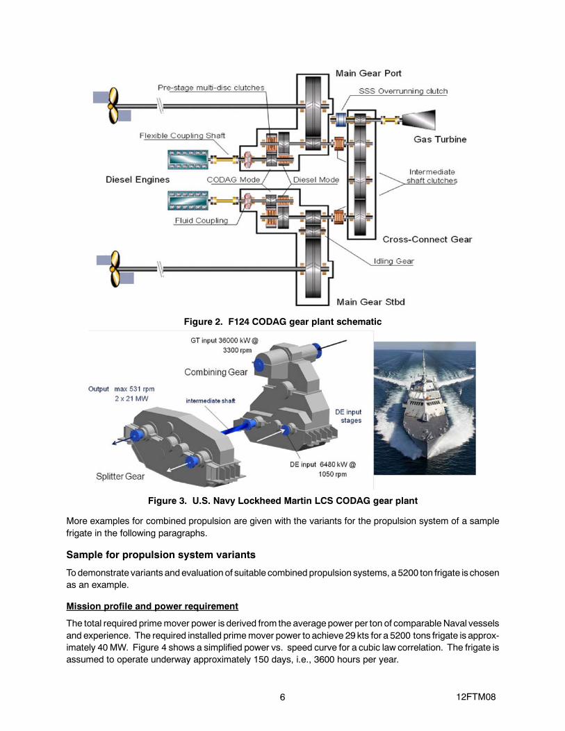
The Lockheed Martin LCS monohull type (Freedom class) of the US Navy features a completely differentpropulsion train technology. Four water jets are driven by two symmetrically arranged CODAG systems,where the high speed combining gear and the low speed splitter gear are separately installed, linked by longintermediate shafts each, seeFigure 3. Gas turbines and diesel engines canbe engagedseparately in cruiseor higher speed propulsionmodes, or jointly drive thewater jets achieving a top speed in excess of 40 knots inthis CODAGmode. Tomatch with different required water jet speeds, the diesel engine inputs are equippedwith two gear stages where the adequate gear ratio is selected via a multi disc clutch engagement.
6 12FTM08
Figure 2. F124 CODAG gear plant schematic
Figure 3. U.S. Navy Lockheed Martin LCS CODAG gear plant
More examples for combined propulsion are given with the variants for the propulsion system of a samplefrigate in the following paragraphs.
Sample for propulsion system variants
Todemonstrate variants andevaluation of suitable combined propulsion systems, a 5200 ton frigate is chosenas an example.
Mission profile and power requirement
The total required primemover power is derived from the averagepower per ton of comparable Naval vesselsand experience. The required installed primemover power to achieve 29 kts for a 5200 tons frigate is approx-imately 40 MW. Figure 4 shows a simplified power vs. speed curve for a cubic law correlation. The frigate isassumed to operate underway approximately 150 days, i.e., 3600 hours per year.

7 12FTM08
Figure 4. Power requirement for a 5200 ton frigate vs. speed
Based on current ship programs and experience, the speed profile as shown in Table 2 is applied for theevaluation.
Prime movers and basic propulsion system arrangement
The propulsion system is based on diesel engines of approximately 1000 to 1300 rpm and gas turbines of3300 to 3600 rpm. Diesel engines provide better fuel efficiency across the load and speed spectrum thanother fossil fueled alternatives like gas turbines. Diesel engines maintain reasonable efficiency down to lowload levels of approximately 15%. Gas turbines feature lowdeadweight and volumeat ratedpower and there-fore providehigher power density thandiesel engines. Acombinedpropulsionsystem, combining twoormoreprime movers to one or more propulsors, further optimizes speed and endurance.
Diesel engines and gas turbines of different manufacturers are considered in this paper. However, for anypropulsion system configuration, alternative manufacturers can be adopted without major changes to thebasic features of the propulsion system performance.
The frigate is assumed to have two propeller shafts with CPPs and will be operated using both propellersexcept in case of emergency.
Requirements summary
Table 3 shows anoverview of the assumedbasic specs for the frigate. Any changes to these specsmayhavean impact on the final selection of prime movers and referring gear specs but will basically not affect thecomparative aspects of the different propulsion system arrangements.
Propulsion system arrangements
Overview
Five different propulsion system arrangements are investigated as potential solutions for the frigate’s powerplant. The features and performance of each arrangement are evaluated against pertinent parameters listedearlier. Table 4 shows an overview of the subject arrangements.
Table 2. Frigate mission profile
Mode Speed, kts % of time Propeller shaft power, MWIdle 0 5 0Loitering 6 5 0.35Low patrol 13 10 3.5High patrol 18 60 9.3Transit 24 15 22.1Sprint 29 5 39.0

8 12FTM08
Table 3. Frigate basic specs
Displacement 5200 metric tonsSprint speed 28+ ktsOperating hours 3600 per yearPropulsion power approx. 40 MWPropulsors 2 CPPPrime movers High speed diesel engines
Gas turbinesElectric motors
Table 4. Propulsion system variants
A: CODAD B: CODELOD C: CODOGD: CODELAG
with CCE: CODAGwith CC
MW @ rpmFuel1),g/kWh No
Power,MW No
Power,MW No
Power,MW No
Power,MW No
Power,MW
DE 20V 9.1 1150 195 4 36.4 4 36.4 0 2 18.2
DE 12V 5.4 1000 195 2 (10.8)
GT1 21 3600 225 2 42 0 1 21
GT2 32 3300 225 1 32
Gen--set DE 12V 5.2 1000 2102) 1 (5.2) 2 (10.4)
Electric motor 1 2.4 1800 2283) 2 (4.8)
Electric motor 2 4.7 150 2283) 2 9.4
Total input shaftpower 36.4 36.4 42 41.4 39.2
Max speed, kts 28.0 28.0 29.4 29.2 29.0
NOTES:1) At nominal load.2) Generator efficiency considered.3) Generator, converter, and electric motor efficiency considered.
A final solution is not restricted to one of these proposed arrangements but could also be any combination ofindividual primemovers, gear components, andpropulsors. However, thebasic performance features canbeclearly seen from the comparison and a selection is hereby facilitated.
Variant A: CODAD
The CODAD system features more than one diesel engine per propulsor and offers significant flexibility inrunningeither of theengines individually or both (or more) simultaneously. The proposed system comprises 4equal diesel engines, rated 9.1MW, where two of which are connected to each, port and starboard combininggear. Figure 5 shows one of many possible propulsion systems, Figure 6 the principal gear arrangement of adifferent configuration.
Figure 5. CODAD propulsion system

9 12FTM08
Figure 6. CODAD gear arrangement variant
CODAD enables the propulsion system to run up to 80% of sprint speed (i.e., 22 kts) with only two of fourdiesel engines in operation, saving operating time and providing the opportunity for maintenance on non--op-erating engines while underway. In case of damage to one of the diesel engines, up to three engines can stillbe used retaining a max speed of 25 kts and full maneuverability.
Variant B: CODELOD
A fully integrated sole electric propulsion system (IEP) is not considered for the following reasons:
S Acombinedpropulsion systembrings primemovers on line as requiredand canminimize operating hoursof individual units thereby reducing maintenance and repair.
S With a well designed system, a mechanical propulsion has a full load efficiency in the range of 98%whereas an electric drive has an efficiency of about 90--92%. This discrepancy would be even moresignificant considering operation at low loads.
S Electric propulsion requires extensive electric and electronic equipment which easily compensates forany benefit with respect to required deck area, weight, survivability and reliability.
S The overall investment cost for electric propulsion is higher than for a mechanical solution.
A completely different approach is a combined mechanical and diesel electric system, often called a hybridpropulsion system. Such systems feature a main mechanical propulsion with diesel engines and a power--take--in (PTI) operated with an electric motor for loitering at low power with very low noise generation and stillacceptable fuel efficiency, as the nominal load of the motor is moderate. Power generation for the electricmotor can be intelligently combined with the integrated ship power system and temporarily be used for hoteland electrical weapon systems. Figure 7 shows the principal CODELOD propulsion system, Figure 8 thegear arrangement. There are multiple ways of connecting the electric motor to the gear, where two differentsolutions are shown in the principal and the gear arrangement.

10 12FTM08
Figure 7. CODELOD propulsion system
Figure 8. CODELOD gear arrangement
CODELODsystems feature a favorable combination of the characteristics of amechanical systemwith dieselengine propulsion and an electric drive. For higher maximum propulsion power requirements, the diesel en-ginesmay be substituted by gas turbines, building aCODELOG (COmbinedDiesel--ELectricOrGas turbine)system. The newly launched USS Makin Island utilizes such a CODELOG approach. It has two GE LM2500+ gas turbines as prime movers and two 3.5 MW electric motors for auxiliary propulsion.
Variant C: CODOG
TheCODOG configurationwithout a cross connect gear, Figure 9, has been applied onmore than 50 frigatesby many Navies worldwide. It includes two individual propulsion systems for the two propellers. A simultan-eous use of diesel engines and gas turbines is not possible – they can only be used either/or. Power isautomatically switched from one to the other primemover bymeans of automatic, self synchronizingoverrun-ning clutches. CODOG is the predecessor of CODAG and is easier to control. It is particularly applicablewhere the power of the diesel engines is low compared to the gas turbines, so that adding the diesel enginepower to the gas turbine power would only result in a very low incremental speed. Figure 10 shows a typicalCODOG gear arrangement.

11 12FTM08
Variant D: CODELAG
Figure 11 shows an advancedCODELAG propulsion system configuration. The center arranged gas turbineis only used just for high transient and sprint speed (> 17 kts), the majority of the operational time is coveredwith the two electric motors providing a power of 4.7MWeach. The electric motors are located in line with thepropeller shaft in front of the main gears. By means of specifically developed propeller shaft clutches (APC)integral with the main reduction gear, the shaft lines are disengaged from the gears in electric mode. Hence,the reduction gear set is designed only for the gas turbine mode with the gears being at standstill in electricmode. In gas turbine mode, the electric modes can be disengaged with separate multi disk clutches. InCODELAG mode, all prime movers add their power for sprint speed propulsion.
Figure 9. CODOG propulsion system
Figure 10. CODOG gear arrangement

12 12FTM08
Figure 11. CODELAG propulsion system
Variant E: CODAG with cross connect gear
ACODAG systemwith a cross connect gear was first introduced for theGermanNavy type 124 frigates. Thefirst propulsion system was delivered in 1999. The basic principle is the same for the propulsion system vari-ants shown in Figure 12 and Figure 13. The center arranged gas turbine is only used for high transient andsprint speed (> 18 kts), the majority of the operational time is covered with the two diesel engines featuring apower of 9.1 MW each. The system can be operated fully flexible with one diesel engine driving bothpropellers, twodiesels separately driving the referring propellers, thegas turbinedriving both propellers or, forsprint speed, with all prime movers commonly used for maximum propulsion power.
Propulsion system evaluation
Fuel economy
Considering the specific fuel consumption of the primemovers for the four propulsion configurations, the fuelconsumption per nautical mile vs. vessel speed is shown in Figure 14. Gear efficiency is considered for allfuel consumption figures, electrical conversion losses are taken account for with the CODELOD andCODELAGsolutions. In apatrol of 5000 nmaccording to themissionprofile listed in Table 2, the frigatewouldconsume fuel (propulsion only) as listed in Table 5 for the different propulsion systems. The overallconsumption is very close for all configurations.
Figure 12. CODAG propulsion system schematic

13 12FTM08
Figure 13. CODAG propulsion plant for the U.S. Coast Guard national security cutter
Figure 14. Specific fuel consumption
Table 5. Total fuel consumption for a 5000 nm patrol in metric tons
CODAD CODELOD CODAG CODELAGw/CC
CODAGw/CC
5000 nm patrol (tons) 680 663 703 717 722

14 12FTM08
Maintenance and repair
Maintenance and repair costs are determined by the hours of operation and loads on the prime movers.Combined systems operate only the prime movers which are needed to provide the actually requiredpropulsion power. Thereby, fuel is saved by operating at a more favorable specific fuel consumption and,more importantly, operating hours accumulate on reduced basis per individual prime mover thus enablinglonger intervals between maintenance and lowering repair cost.
Figure 15 shows the cubic propeller curve, the mission profile as per Table 2, and the required primemoversto achieve the referring vessel speed. It is obvious, that combined systems and multiple prime movers cansave operating time for the individual primemover and thereby significantly extend the time interval betweenmaintenanceperiods. Accumulatedoperating hours for diesel engines andelectricmotors are summarized inFigure 16.
Location flexibility
Leading gear makers have demonstrated their ability to design, manufacture, and install reduction gears inthe new forms of mono-- and multi--hulls with very confined engine room space. Additionally, combinedpropulsion systems are designed on an open architecture basis in respect to the ability to operate with thepopular platform management systems and with any appropriate prime mover or propulsor.
Figure 15. Prime movers in operation

15 12FTM08
Figure 16. Accumulated operating hours
Survivability
Three of the reduction gear alternatives:
S CODAD
S CODELOD
S CODOG
involve individual gear units which solely serve prime movers dedicated to an individual propeller shaft.Therefore, the engine compartments can be separated by a longitudinal, water tight bulkhead. If one enginecompartment sustains damage, the other can survive and provide propulsion power.
CODELAG and CODAG with a cross--connect gear have a common engine compartment for the reductiongear system as themain gears aremechanically linked by the cross--connect gear. The gear compartment isbetween the aft engine compartment and the ahead diesel engine or the gas turbine compartment andseparated in each case by a transverse, water tight bulkhead.
The individual gears can be built water tight and operate under a water depth of up to six meters over thepropeller shafts. The gears can be engaged and disengaged on a remote basis even if under water. If allautomatic control systems fail, the gears can be manually engaged and disengaged.
The CODELAG and CODAG plant with a cross--connect gear can sustain various types of damage and stillenable ship propulsion as listed in Table 6. Considering all criteria, CODELAG or CODAGwith CC turn out tobe the arrangements with the highest redundancy in case of partial damage.
Table 6. Damage and remaining operation modes for CODELAG or CODAG with CC
Type of damage Resulting operating modeOne EM/DE inoperable GT or other EM/DE operating on both
propellersTwo EM/DE inoperable GT operates one or two propeller shaftsCross connect gear inoperable Each EM/DE drives its own propeller shaftOne main gear and cross connect gearinoperable
EM/DE on other main gear and referring shaft
Gear compartment flooded All modes possible

16 12FTM08
Signature
The key enabler in a combined propulsion system is the reduction gear which transmits the power from any orall of the prime movers to the propulsors as speed and operational conditions require. The gear systempermits theprimemovers to be locatedat favorable positionswithin theengine compartment(s). This requirescomplex gear transmission systemswhere thepower transmitting gears aswell as the idling gearmeshes area potential source of air borne and structure borne noise.
Optimum gear design considering basic parameters such as module, helix angle, pressure angle and facewidth matched with grinding tolerances to plus or minus several microns and furthermore high quality manu-facturing can produce a gear system that confines structure borne noise to a level which is below customerspecification. This is even possible without elastic mountings or dampening fluid couplings. There are onlyfew gear manufacturers worldwide who succeeded in producing gears meeting the required noise levels forfrigates like the example discussed in this paper.
Further improvement of noise development can be made with CODELOD in EM drive mode. The electricpower can be generated within an encapsulated area of a gen--set and little torsional vibration excitation istransmitted to the drive train. Ultimate low noise drive is possible with CODELAG, where the complete geartrain can be disconnected in electric drive mode with the gears remaining at standstill.
Hybrid drive evaluation
The hybrid variants CODELOD and CODELAG have the following advantages over CODAD, CODOG andCODAG:
S Maintenance and overhaul of main DE reduced in proportion with electric motor use. Electric motormaintenance is insignificant.
S Low power operation of GT (especially with CODOG) with extremely high fuel consumption can beavoided.
S In low load operation, deposits may form in DE combustion chambers. DE operation at less than 10%load limited to between 40 and 100 hours before relievinghigher loadoperation of several hours required.
S Fuel consumption and emissions (soot and other harmful atmospheric emissions) reduced as low loadmain diesel shifted to high load generator set.
S Loitering operation with extremely low noise emission, especially if gears can be disengaged.
System validation by advanced calculation
Combinedmarine propulsion systems are complexmechanical systemswith multiple potential failuremodesregarding individual components and system behavior. Traditional design calculations, according to a classi-fication society, only provide a certain level of risk reduction, especially for individual components. Cost andtight schedule do not allow for extended harbor and sea trials and rectification of unexpectedly upcomingfailures and system performance deficiencies.
The small numbers of produced gear units for a specific application make it impractical on a cost and timebasis to test and optimize new designs of propulsion systems with prototypes. Prototype testing needs to bereplaced by a conservative design approach, primarily based on experience over several decades and com-mon calculation methods. To further reduce the risk of system based problems, the traditional methods areincreasingly supported with the use of numeric simulation calculations. Well established methods such astorsional or lateral vibration calculations only providepartial informationon increasingly complex systemsandtransient mode dynamic behavior.
The shortcomings can be reduced or even overcome with a modern dynamic calculation tool such as MultiBody Simulation (MBS). With the help of MBS, the complete propulsion system is transferred to a computermodel using standard elements such as masses, spring stiffnesses and damping parameters. With thisnumericmodel, the dynamic behavior of the complete systemcanbe investigatedwith respect to eigenmodesand referring critical excitations. Moreover, within the so--called timedomain simulation,MBS can investigate
17 12FTM08
the response of the system on normal or unusual operating modes. The mode in question is applied to themodel by a forceor torqueover timesignal applied to the referring place in the system. The dynamic responseat any other place of the model reveals the dynamic loads on the referring components.
Multi body simulation (MBS) -- Example
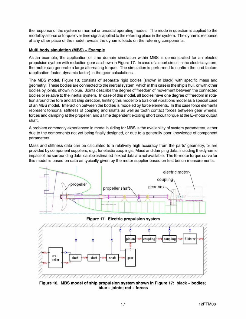
As an example, the application of time domain simulation within MBS is demonstrated for an electricpropulsion system with reduction gear as shown in Figure 17. In case of a short circuit in the electric system,the motor can generate a large alternating torque. The simulation is performed to confirm the load factors(application factor, dynamic factor) in the gear calculations.
The MBS model, Figure 18, consists of separate rigid bodies (shown in black) with specific mass andgeometry. These bodies are connected to the inertial system,which in this case is the ship’s hull, or with otherbodies by joints, shown in blue. Joints describe the degree of freedom of movement between the connectedbodies or relative to the inertial system. In case of this model, all bodies have one degree of freedom in rota-tion around the fore and aft ship direction, limiting this model to a torsional vibrationsmodel as a special caseof an MBSmodel. Interaction between the bodies is modeled by force elements. In this case force elementsrepresent torsional stiffness of coupling and shafts as well as tooth contact forces between gear wheels,forces and damping at the propeller, and a time dependent exciting short circuit torque at the E--motor outputshaft.
A problem commonly experienced in model building for MBS is the availability of system parameters, eitherdue to the components not yet being finally designed, or due to a generally poor knowledge of componentparameters.
Mass and stiffness data can be calculated to a relatively high accuracy from the parts’ geometry, or areprovided by component suppliers, e.g., for elastic couplings. Mass and damping data, including the dynamicimpact of the surroundingdata, canbeestimated if exact data are not available. The E--motor torque curve forthis model is based on data as typically given by the motor supplier based on test bench measurements.
Figure 17. Electric propulsion system
Figure 18. MBS model of ship propulsion system shown in Figure 17: black -- bodies;blue -- joints; red -- forces

18 12FTM08
The damping parameters are generally not very well known for most components and usually have to be es-timated based on experience or reference testing. Damping parameters in propulsion systems have no im-pact on the determination of the eigenmodes; main focus of dynamic calculations is to avoid such modes.Therefore, the lack of reliable damping parameters does not limit this part of the MBS calculations. However,limitation for not calibrated models (i.e., models where the damping parameters are not derived from experi-ment) lies in limited accuracywhen determiningpeak torques/forces in the time domain simulation for specifictorque or force excitation as described in this example or for operation conditions in resonance modes whichmay be transient or cannot be avoided for specific reasons.
The model presented uses damping parameters at the propeller based on approximation algorithms and inthe gear mesh based on default values from other models. The simplified MBS 3D model is shown inFigure 19 for the same system as shown in Figure 18. Gearwheels and tooth contact aremodeled in detail tosimulate variable stiffness for different positions on the path of contact and potential negative tooth load,meaning alternating torque and gear hammering. Gear hammering leads to increased tooth contact forcesupon re--contact of the tooth flanks and unwanted gear noise. With respect to system dynamics, hammeringadds a variable stiffness to the model, which may cause chaotic system behavior. This condition can only behandled by numeric simulation such as MBS rather than by analytic methods.
The model calculation is started and transferred to a steady state operation point in the first 10 seconds ofsimulation time. After these 10 seconds, the torque excitation as shown in Figure 20 is simulated at the elec-tric motor shaft, starting with time “0” in the diagrams.
Figure 19. Simplified 3D model -- joints and force elements not shown
Figure 20. Simulated electric short circuit dynamic torque excitation at the electric motor shaft

19 12FTM08
The resulting input torque at the gear box is shown in Figure 21. It can be derived from this graph that thedynamic peak torque as compared to nominal torque reaches a factor of approximately 1.7 for this propulsionsystem with the defined short circuit dynamic torque excitation. The resulting tooth contact force in the gearmesh is shown inFigure 22. Themaximumdynamic tooth load reaches a factor of approximately 1.8 as com-pared to nominal tooth load. This is to be considered to cover both, application factor, KA, and dynamic factor,Kv. Negative torque figures and consequential tooth hammering do not occur.
Figure 21. Resulting torque at the gear box input flange
Figure 22. Resulting tooth contact force in the gear mesh

20 12FTM08
General considerations on multi body simulation
Dynamic load factor values as determined by MBS within the time domain simulation can help to validate thetraditional calculations performed during design. However, a direct comparison with classic design loadfactors may be difficult, because these are based on experiment and experience in combination with specificanalytic calculationmethods. Theanalytic designmethods are coherent within themselves, but not necessar-ily with the numeric calculations, therefore caution is necessary. The use of MBS to validate a design withrespect to classification rules is limited by specific requirements from the classification societies. Priorindividual clarification is necessary.
Themain advantage of MBS becomes apparent whenmodels becomemore complex than torsional vibrationmodels. Such calculations may include the behavior of gear boxes elastically mounted to the foundation incombinationwith attached shafts and couplings, including longitudinal and lateral mode shapes of the shafts.
Due to the complexity of the MBS calculation as compared to analytic torsional or lateral vibration calculationmethods, MBS may not in any case be the best choice for early development. This is also due to the lack ofreliable data formodeling at anearly design stage. Therefore, theuseofMBSat themoment is limited tomorecomplicatedproblems, forwhichnoother tools exist. After final designof complexmarine propulsion systemssuch as combined systems as described earlier in this paper, final validationwith MBS is strongly recommen-ded. It is a challenge to performsuchMBSearly enough to beable to reasonably react on undesirable systembehavior before construction has progressed too far. MBS therefore needs to be an integratedelement of theprogram schedule.
Conclusions
S Propulsion systems of surface naval vessels are to be specifically adapted ona caseby casebasis. Maindrivers are efficiency, long term durability for extended operation without coastal reach, and minimizedmaintenance requirements.
S Many propulsion system variants are available supported by enhanced prime mover technology,including electric motors.
S Most sophisticated main reduction gear trains enable the various modes of operation.
S Due to the increasing complexity and number of variants of combined propulsion systems, the selectionprocess for a distinct drive train is becoming more andmore difficult. Together with all propulsion expertsinvolved, it should be defined already in an early project phase what technical solutions are feasible for aspecific vessel type; the selection should be based on the various parameters mentioned in this paper.
S Multi body simulation (MBS) is a powerful simulation tool for design evaluation and validation. It is still achallenge to integrate MBS already with the design of the propulsion system.
References
[1] Weiss, Toni; Hoppe, Franz: High SpeedGears for Extreme Applications in Industrial and Marine Fields.Proceeding Conference Verein Deutscher Ingenieure (VDI), September 2005
[2] Hoppe, Franz: Naval Gear systems and their future demands. Proceeding Conference INEC 2008,Hamburg, June 2008.
[3] Hoppe, Franz; Pinnekamp, Burkhard: Gear Noise – Challenge and Success based on Optimized GearGeometries. AGMA Fall Technical Meeting, Milwaukee, October 2004
[4] Pinnekamp, Burkhard: Optimization of Marine Propulsion Systems with Modern Tools. ProceedingsRENK Symposium, Augsburg, Germany, June 8, 2011.
[5] Hoppe, Franz: Marine Gears in the Environment of Naval Propulsion. Proceedings RENK Symposium,Augsburg, Germany, June 8, 2011.
[6] Hoppe, Franz: Hybrid propulsion combining gears and systems for naval vessels. Proceeding Confer-ence INEC 2012, Edinburgh, UK, May 15--17, 2012.