levelonedownload.level1.com/level1/manual/whg-1000_um_v1.0.pdf3 combine whg-1000 to the network...
TRANSCRIPT

i
LevelOne
WHG-1000
300Mbps Wireless PoE Hotspot Gateway
User Manual
V1.00

ii
Table of Contents 1 Before You Start .......................................................................................................... 1
1.1 Preface .................................................................................................................................................. 1
1.2 Document Conventions .................................................................................................................. 1
1.3 Package Checklist ............................................................................................................................. 2
2 System Overview and Getting Started .......................................................... 3
2.1 Introduction of WHG-1000 ........................................................................................................... 3
2.2 System Concept ................................................................................................................................ 3
2.3 Hardware Descriptions ................................................................................................................... 5
2.4 System Requirement ...................................................................................................................... 9
2.5 Installation Steps ............................................................................................................................. 9
2.6 Access Web Management Interface ........................................................................................ 11
3 Combine WHG-1000 to the Network ............................................................ 13
3.1 Network Requirement ................................................................................................................... 13
3.2 Configure WAN Port ....................................................................................................................... 13
3.2.1 Static IP ...................................................................................................................................................... 14
3.2.2 Dynamic ..................................................................................................................................................... 14
3.2.3 PPPoE ........................................................................................................................................................... 14
3.3 Internet Connection Detection .................................................................................................. 16
3.4 WAN Bandwidth Control .............................................................................................................. 17
3.5 What is Zone .................................................................................................................................... 18
3.5.1 Port Role Assignment ............................................................................................................................ 19
3.5.2 Planning Your Internet Network ........................................................................................................ 20
3.5.3 Configure Zone Network ...................................................................................................................... 21
4 Let Your Network to Be a Wireless Network ........................................... 23
4.1 System Wireless General Settings ........................................................................................... 23
4.2 Zone Wireless Settings................................................................................................................. 25
4.3 Zone Wireless Security................................................................................................................. 28
5 Who Can Access the Network ........................................................................... 30
5.1 Type of Users ................................................................................................................................... 30
5.1.1 Local ..................................................................................................................................................... 31
5.1.2 RADIUS ................................................................................................................................................ 34
5.1.3 On-Demand Users ........................................................................................................................... 36
5.2 User Login ......................................................................................................................................... 44
5.2.1 Default Authentication ................................................................................................................... 44
5.2.2 Login with Postfix............................................................................................................................. 44
5.2.3 An Example of User Login ............................................................................................................ 45
6 Restrain the Users ................................................................................................... 47
6.1 Black List ........................................................................................................................................... 47

iii
6.2 MAC Address Control .................................................................................................................... 49
6.3 Policy ................................................................................................................................................... 50
6.3.1 Firewall ................................................................................................................................................ 52
6.3.2 Routing ................................................................................................................................................ 55
6.3.3 Schedule ............................................................................................................................................. 57
6.3.4 QoS Profile ......................................................................................................................................... 58
6.3.5 Session Limit ..................................................................................................................................... 59
7 Access Network without Authentication .................................................... 60
7.1 DMZ ..................................................................................................................................................... 60
7.2 Virtual Server ................................................................................................................................... 61
7.3 Privilege List ..................................................................................................................................... 62
7.3.1 Privilege IP ................................................................................................................................................ 63
7.3.2 Privilege MAC ............................................................................................................................................ 64
7.4 Disable Authentication in Public Zone .................................................................................... 65
8 User Login and Logout .......................................................................................... 66
8.1 Before User Login ........................................................................................................................... 66
8.1.1 Login with SSL ......................................................................................................................................... 66
8.1.2 Internal Domain Name with Certificate .......................................................................................... 67
8.1.3 Walled Garden .......................................................................................................................................... 69
8.1.4 Walled Garden AD List .......................................................................................................................... 70
8.2 After User Login .............................................................................................................................. 71
8.2.1 Portal URL after successful login ....................................................................................................... 71
8.2.2 Idle Timer .................................................................................................................................................. 72
8.2.3 Multiple Login ........................................................................................................................................... 73
9 Networking Features of a Gateway ............................................................... 74
9.1 IP Plug and Play .............................................................................................................................. 74
9.2 Dynamic Domain Name Service (DDNS) .............................................................................. 75
9.3 Port and IP Redirect ...................................................................................................................... 76
10 System Management and Utilities ................................................................. 77
10.1 System Time ................................................................................................................................ 77
10.2 Management IP ........................................................................................................................... 78
10.3 User Log Access IP Address ................................................................................................... 79
10.4 SNMP ............................................................................................................................................... 80
10.5 Three-Level Administration .................................................................................................... 81
10.6 Change Password ....................................................................................................................... 83
10.7 Backup / Restore and Reset to Factory ............................................................................. 85
10.8 Firmware Upgrade ..................................................................................................................... 86
10.9 Restart ............................................................................................................................................ 87
10.10 Network Utility ............................................................................................................................ 88
10.10.1 Wake-on-LAN....................................................................................................................................... 88
10.10.2 Ping ......................................................................................................................................................... 88

iv
10.10.3 Trace Route .......................................................................................................................................... 89
10.10.4 Show ARP Table .................................................................................................................................. 89
10.11 Monitor IP Link ............................................................................................................................ 90
10.12 Console Interface ....................................................................................................................... 91
11 System Status and Reports ................................................................................ 94
11.1 View the Status .......................................................................................................................... 94
11.1.1 System Status ....................................................................................................................................... 94
11.1.2 Interface Status .................................................................................................................................... 96
11.1.3 Routing Table ......................................................................................................................................... 98
11.1.4 Current Users ......................................................................................................................................... 99
11.1.5 User Log ................................................................................................................................................. 100
11.1.6 Local User Monthly Network .......................................................................................................... 102
11.2 Notification ................................................................................................................................. 103
11.2.1 E-Mail ...................................................................................................................................................... 104
11.2.2 SYSLOG .................................................................................................................................................. 105
11.2.3 FTP ........................................................................................................................................................... 106
11.2.4 Event Log .............................................................................................................................................. 107
12 Advanced Applications ........................................................................................ 108
12.1 Upload/Download Local Users Accounts ......................................................................... 108
12.2 RADIUS Advanced Settings .................................................................................................. 110
12.3 Roaming Out .............................................................................................................................. 111
12.4 Customizable Pages ................................................................................................................ 112
Appendix A. Network Configuration on PC & User Login .................................... 114
Appendix B. Policy Priority .................................................................................................... 127
Appendix C. WDS Management .......................................................................................... 128
Appendix D. RADIUS Accounting ....................................................................................... 129
Appendix E. On-demand Account types & Billing Plan ......................................... 138
Appendix F. External Payment Gateways .................................................................... 147
User‟s Manual WHG-1000 Wireless Hotspot Gateway ENGLISH
1
1 Before You Start
1.1 Preface
This manual is for WLAN service providers or network administrators to set up a network environment
using the WHG-1000 system. It contains step-by-step procedures and graphic examples to guide MIS
staff or individuals with slight network system knowledge to complete the installation.
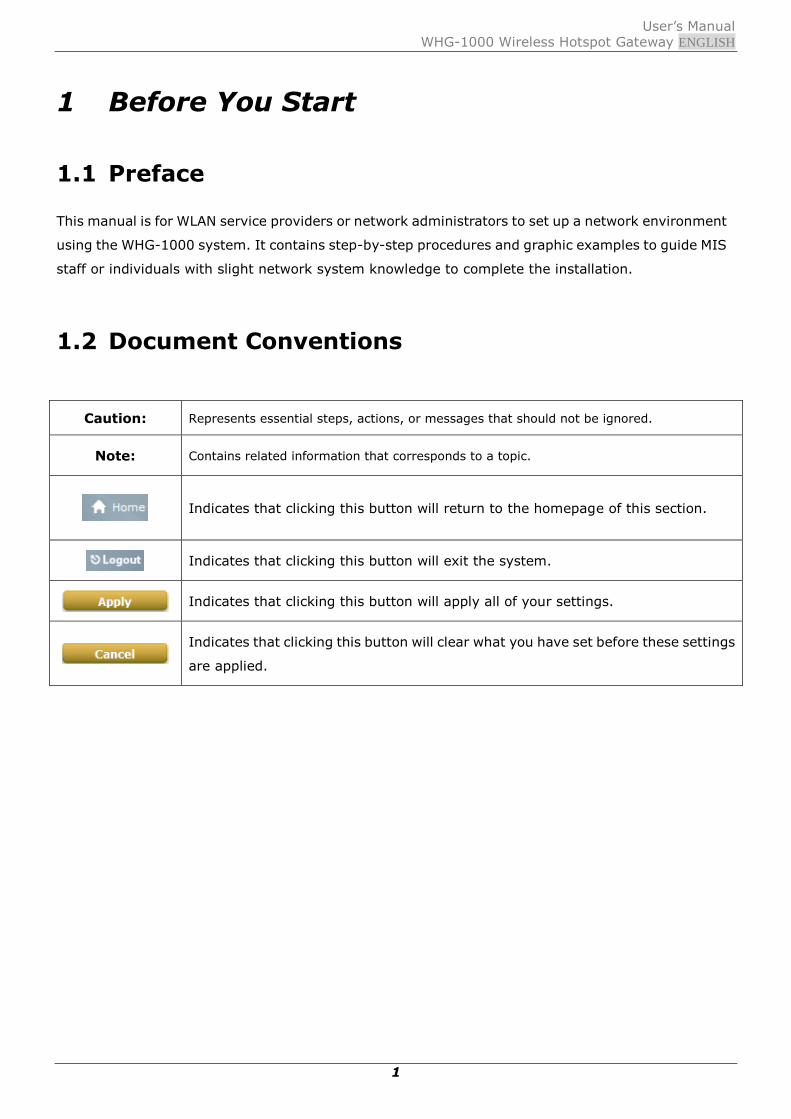
1.2 Document Conventions
Caution: Represents essential steps, actions, or messages that should not be ignored.
Note: Contains related information that corresponds to a topic.
Indicates that clicking this button will return to the homepage of this section.
Indicates that clicking this button will exit the system.
Indicates that clicking this button will apply all of your settings.
Indicates that clicking this button will clear what you have set before these settings
are applied.

User‟s Manual WHG-1000 Wireless Hotspot Gateway ENGLISH
2
1.3 Package Checklist
The standard package of WHG-1000 includes:
WHG-1000 x 1
CD-ROM (with User‟s Manual and QIG) x 1
Quick Installation Guide (QIG) x 1
Console Cable x 1
Ethernet Cable x 1
Power Adapter (DC 12V) x 1
Rubber Antenna x 2
Mounting Kit x 1
Ground Cable x 1
Caution:
It is highly recommended to use all the supplies in the package instead of substituting any
components by other suppliers to guarantee best performance.

User‟s Manual WHG-1000 Wireless Hotspot Gateway ENGLISH
3
2 System Overview and Getting Started
2.1 Introduction of WHG-1000
The WHG-1000 is the most economical and feature rich Wireless Hotspot Gateway, targeting
mini-size stores that want to provide small, single-point wireless Internet access service. WHG-1000
is a perfect choice for beginners to run hotspot businesses. It does not cost much compared to buying
a pile of equipments, nor does it take the skills of an expert to glue multiple applications out of
multiple freeware. Feature-packed for hotspot operation, WHG-1000 comes with built-in 802.11
n/b/g MIMO access point, web server and web pages for clients to login, easy logo-loading
for branding a hotspot store, simple user/visitor account management tool, payment plans,
multiple credit card gateways, traffic logs, IP sharing and etc. WHG-1000 also brings in an
extra advantage - the wall-mountable, dust-proof (IP50) metal housing.
2.2 System Concept
WHG-1000 is capable of managing user authentication, authorization and accounting. The user
account information is stored in the local database or a specified external RADIUS database server.
Featured with user authentication and integrated with external payment gateway, WHG-1000 allows
users to easily pay the fee and enjoy the Internet service using credit cards through a variety of
payment gateways including Authorize.Net, PayPal, SecurePay, and WorldPay. Furthermore,
WHG-1000 introduces the concept of Zones – Private Zone and Public Zone, each with its own
definable access control profiles. Private Zone means clients are not required to be authenticated
before using the network service. On the other hand, clients in Public Zone are required to get
authentication before using the network service. This is very useful for hotspot owners seeking to
deploy wireless network service for clients and manage the network as well. The following diagram is
an example of WHG-1000 set to manage the Internet and network access services at a hotspot venue.

User‟s Manual WHG-1000 Wireless Hotspot Gateway ENGLISH
4
【Example: A typical Hotspot network】

5
2.3 Hardware Descriptions
Front Panel
1 USB For future usage only.
2 WES Press to start running WES (WDS Easy Setup)
process.
3 Console Attach the RS-232 console cable here, for
management use only.
4 LAN1/LAN2 Attach Ethernet cables here for connecting to the
wired local network. LAN1 maps to Private Zone and
requires no user authentication, LAN2 maps to Public
Zone and by default requires user authentication.
5 WAN (PoE) Attach the wired external network here. This port
supports Power over Ethernet (PoE) for flexible
installation.
6 Reset This is hardware reset button. Press once to restart
the system.
7 Power Socket
(12VDC/1A)
For connecting to external power supply via the
power adapter.
Rear Panel

6
Antenna Connector Attach antennas here. WHG-1000 supports 1 RF
interface with 2 SMA connectors.
7
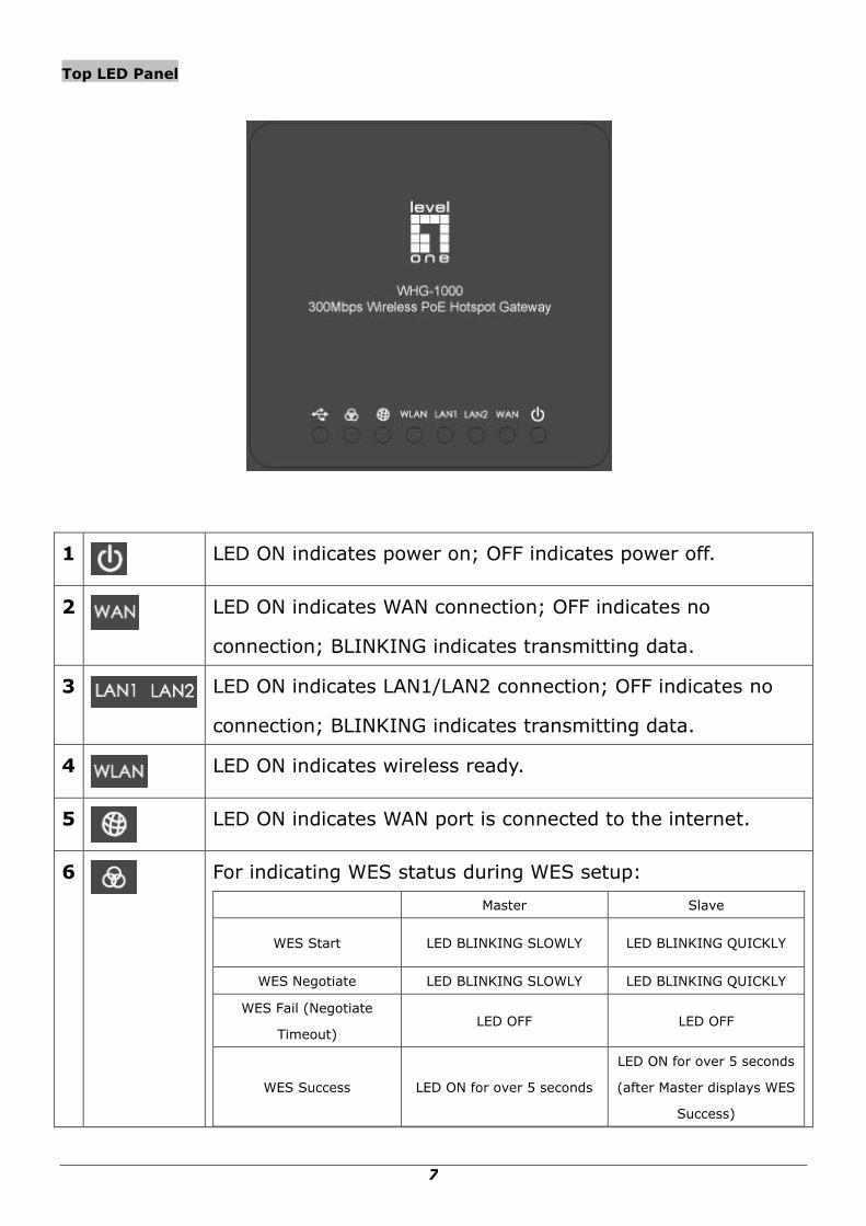
Top LED Panel
1
LED ON indicates power on; OFF indicates power off.
2
LED ON indicates WAN connection; OFF indicates no
connection; BLINKING indicates transmitting data.
3
LED ON indicates LAN1/LAN2 connection; OFF indicates no
connection; BLINKING indicates transmitting data.
4
LED ON indicates wireless ready.
5
LED ON indicates WAN port is connected to the internet.
6
For indicating WES status during WES setup:
Master Slave
WES Start LED BLINKING SLOWLY LED BLINKING QUICKLY
WES Negotiate LED BLINKING SLOWLY LED BLINKING QUICKLY
WES Fail (Negotiate
Timeout) LED OFF LED OFF
WES Success LED ON for over 5 seconds
LED ON for over 5 seconds
(after Master displays WES
Success)

8
7
For future usage only.

9
2.4 System Requirement
Standard 10/100BaseT including network cables with RJ-45 connectors
All PCs need to install the TCP/IP network protocol
2.5 Installation Steps
Please follow the steps below to install WHG-1000:
Please follow the steps mentioned below to install the hardware of WHG-1000:
1. Place the WHG-1000 at a best location.
The best location for WHG-1000 is usually at the center of your wireless network.
2. Connect WHG-1000 to your outbound network device.
Connect one end of the Ethernet cable to the WAN port of WHG-1000 on the front panel.
Depending on the type of internet service provided by your ISP, connect the other end of the cable
to the ATU-Router of an ADSL, a cable modem, a switch or a hub. The WAN LED indicator should be
ON to indicate a proper connection.
3. Connect WHG-1000 to your network device.
Connect one end of the Ethernet cable to the LAN1 port of WHG-1000 on the front panel. Connect
the other end of the cable to a PC for configuring the system. The LAN1 LED indicator should be ON
to indicate a proper connection.
Note:
WHG-1000 has two virtual zones Private and Public which are mapped to
LAN1(192.168.1.254) and LAN2(192.168.11.254) respectively.
4. There are two ways to supply power over to WHG-1000.
(a) Connect the DC power adapter to the WHG-1000 power socket on the front panel.
(b) WHG-1000 is capable of transmitting DC current via its WAN PoE port. Connect an IEEE
802.3af-compliant PSE device, e.g. a PoE-switch, to the WAN port of WHG-1000 with the
Ethernet cable.
Now, the hardware installation is completed.

10
Caution:
Please only use the power adapter supplied with the WHG-1000 package. Using a different power
adapter may damage this system.
Caution:
To double verify the wired connection between WHG-1000 and your switch/router/hub, please check
the LED status indication of these network devices.

11
2.6 Access Web Management Interface
WHG-1000 supports Web Management Interface (WMI) configuration. Upon the completion of
hardware installation, WHG-1000 can be configured via web browsers with JavaScript enabled such as
Internet Explorer version 6.0 and above or Firefox.
Default LAN interface IP address:
LAN1 (192.168.1.254) is mapped to Private Zone with no authentication is required for users.
LAN2 (192.168.11.254) is mapped to Public Zone, by default authentication is required for users.
Note: The instructions below are illustrated with the administrator PC connected to LAN1.
To access the web management interface, connect a PC to the LAN Port, and then launch a browse.
Make sure you have set DHCP in TCP/IP of your PC to get an IP address dynamically. The
default gateway IP address is the default gateway IP address of Private Zone: “192.168.1.254”.
Next, enter the gateway IP address of WHG-1000 at the address field. The default gateway IP address
from LAN Port is“https://192.168.1.254” (“https” is used for a secured connection).
The administrator login page will appear. Enter “admin”, the default username, and “admin”, the
default password, in the User Name and Password fields. Click LOGIN to log in.
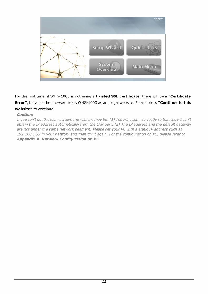
After a successful login, a “Home” page with four main buttons will appear on the screen.
12
For the first time, if WHG-1000 is not using a trusted SSL certificate, there will be a “Certificate
Error”, because the browser treats WHG-1000 as an illegal website. Please press “Continue to this
website” to continue.
Caution:
If you can’t get the login screen, the reasons may be: (1) The PC is set incorrectly so that the PC can’t
obtain the IP address automatically from the LAN port; (2) The IP address and the default gateway
are not under the same network segment. Please set your PC with a static IP address such as
192.168.1.xx in your network and then try it again. For the configuration on PC, please refer to
Appendix A. Network Configuration on PC.

13
3 Combine WHG-1000 to the Network
3.1 Network Requirement
In the general network environment, the main role of WHG-1000 is a gateway that manages all the
network access from internal network to Internet. Thus, the first step is to prepare an Internet
connection from your ISP (Internet Service Provider) and connect it to the WAN port of WHG-1000.
3.2 Configure WAN Port
There are 3 connection types for the WAN Port: Static, Dynamic and PPPoE. These connection types
are enough to support most ISP.
Now, let us discuss how to configure WAN port. Go to: System >> WAN Configuration.
The parameters related to each connection method are described in the following page.

14
3.2.1 Static IP
Static: Manually specifying the IP address of the WAN Port. The fields with red asterisks are
mandatory.
IP Address: The IP address of the WAN port.
Subnet Mask: The subnet mask of the WAN port.
Default Gateway: The gateway of the WAN port.
Preferred DNS Server: The primary DNS Server of the system.
Alternate DNS Server: The substitute DNS Server of the system. This is an optional field.
3.2.2 Dynamic
Dynamic: It is only applicable for the network environment where the DHCP server is available
upstream of the system. Click the Renew button to get an IP address automatically.
3.2.3 PPPoE
PPPoE: When selecting PPPoE to connect to the network, please set the “User Name”, “Password”,
“MTU” and “Clamp MSS”. There is a Dial on demand function under PPPoE. If this function is
enabled, a Maximum Idle Time will be available for input a value. When the idle time is reached, the
system will automatically disconnect itself.

15

16
3.3 Internet Connection Detection
Configure Internet Connection Detection, go to: System >> WAN Traffic.
Internet Connection Detection: When enabled, system will try to access these IP/Domain
addresses, if system can reach these IP/Domain address, it means that the outbound Internet
connection is in normal state. On the other hand, there is a text box available for the administrator
to enter a reminding message. This reminding message will appear on clients‟ screens when
Internet connection is down.

17
3.4 WAN Bandwidth Control
Configure WAN Bandwidth Control, go to: System >> WAN Traffic.
The feature gives administrators control over the entire system‟s traffic though the WAN interface.
These parameters set here should not exceed the real bandwidth coming from your ISP. For example,
if your xDSL is 8Mbs/640kbs, you may input these two values here.
Available Bandwidth on WAN Interface:
Uplink: It specifies the maximum uplink bandwidth that can be shared by clients of the system.
Downlink: It specifies the maximum downlink bandwidth that can be shared by clients of the
system.

18
3.5 What is Zone
Configure Zone, go to: System >> Zone Configuration.
A Zone is a logical network area that covers wired or wireless networks, or both of them. By
associating to a unique ESSID of a Zone, wireless network is divided into different logical zones.
Clients attempting to access the resources within a Zone will be controlled based on the access control
profile of that Zone, such as authentication, security feature, wireless encryption method, traffic
control, and etc.
There are two Zones that can be utilized by WHG-1000 – Private Zone and Public Zone, as shown in
the table below. Private Zone means clients are not required to be authenticated before using the
network service. On the other hand, clients in Public Zone are required to get authentication before
using the network service.
Name: Mnemonic name of the Zone.
ESSID: The SSID that is associated with the Zone.
Wireless Security: Data encryption method for wireless networks within the Zone.
Default Authen Option: Default authentication method/server that is used within the Zone.
Details: Configurable, detailed settings for each Zone.
Click Configure button to configure each Zone: Basic Settings, Authentication Settings (Public
Zone only), Wireless Settings, and WDS Settings (Public Zone only).

19
3.5.1 Port Role Assignment
WHG-1000 supports two zones, Private and Public. In the Private Zone, authentication is not
required to access the network via wired and wireless. In the Public Zone, by default,
Authentication Required is enabled by default, so clients are required to get authenticated
successfully before surfing the Internet.
The Zone and Port mappings are shown below, LAN1 and LAN2 maps to Private Zone and Public
Zone respectively.
Note:
System‟s WMI can also be accesses via WAN port as long as the administrator uses an IP address
listed in Management IP Address List setting. If both WAN and LAN ports are unable to reach
WMI, please use console interface to solve this issue.

20
3.5.2 Planning Your Internet Network
WHG-1000 supports two zones, Private and Public. In the Private Zone, authentication is not
required to access the network via wired and wireless. In Public Zone, by default Authentication
Required is enabled, so clients are required to get authenticated successfully before surfing the
Internet. Administrator can access the Web Management Interface (WMI) of WHG-1000 through
the wired LAN port. Waiters or waitresses can send orders back to the electrical menu system via
wireless hand set devices.

21
3.5.3 Configure Zone Network
Configure Zone network; go to: System >> Zone Configuration. Click the button Configure of
Private zone for further configuration. The parameter descriptions of Basic Settings for Private Zone
and Public Zone are the same. The wireless settings under each zone will be covered in the next
section.
Network Interface:
o Operation Mode: Contains NAT mode and Router mode. When NAT mode is chosen,
the service zone runs in NAT mode. When Router mode is chosen, this zone runs in
Router mode.
o IP Address: The IP Address of this zone.
o Subnet Mask: The subnet Mask of this zone.
DHCP Server: Related information needed on setting up the DHCP Server is listed here.
Please note that when “Enable DHCP Relay” is enabled, the IP address of clients will be
assigned by an external DHCP server. The system will only relay DHCP information from the
external DHCP server to downstream clients of this zone.
o Start IP Address / End IP Address: A range of IP addresses that the built-in DHCP
server will assign to clients.
Note: please change the Management IP Address List accordingly (at System >>
General >> Management IP Address List) to permit the administrator to access the
WHG-1000 admin page after the default IP address of the network interface is
changed.
o Preferred DNS Server: The primary DNS server that is used by this Zone.

22
o Alternate DNS Server: The substitute DNS server that is used by this Zone.
o Domain Name: Enter the domain name for this zone.
o WINS Server: The IP address of the WINS (Windows Internet Naming Service) server
if WINS server is applicable to this zone.
o Lease Time: This is the time period that the IP addresses issued from the DHCP server
are valid and available.
o Reserved IP Address List: Each zone can reserve up to 40 IP addresses from
predefined DHCP range to prevent the system from issuing these IP addresses to
downstream clients. The administrator can reserve a specific IP address for a special
device with certain MAC address.

23
4 Let Your Network to Be a Wireless
Network
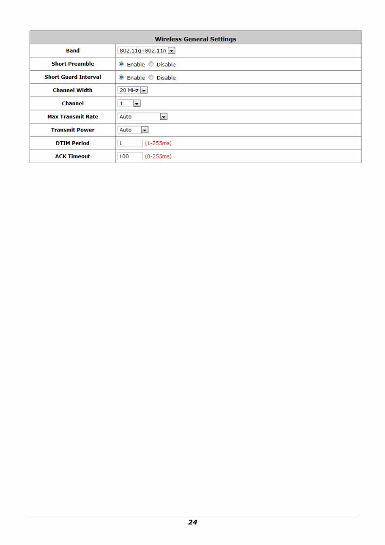
4.1 System Wireless General Settings
Configure System‟s Wireless General Settings, go to: System >> Zone Configuration.
Wireless General Settings:
Band: There are 4 modes to select, 802.11b (2.4G, 1~11Mbps), 802.11g (2.4G, 54Mbps),
802.11b+g, and 802.11g+n.
Short Preamble: The length of the CRC (Cyclic Redundancy Check) block for
communication between the Access Point and roaming wireless adapters. Select Enable for
Short Preamble or Disable for Long Preamble.
Short Guard Interval (802.11g+n only): The guard interval is the space between
symbols (characters) being transmitted to eliminate inter-symbol interference. With
802.11n, short guard interval is half of what it is used to be to increase throughput. Select
Enable to use Short Guard Interval or Disable to use normal Guard Interval.
Channel Width (802.11g+n only): For 802.11n, double channel bandwidth to 40 MHz is
supported to enhance throughput.
Channel: Select the appropriate channel from the drop-down menu to correspond with your
network settings, for example, Channel 1-11 is available in North American and Channel
1-13 in Europe, or choose the default Auto.
Max Transmit Rate: The default is Auto. Available range is from 1 to 54Mbps. The rate of
data transmission should be set depending on the speed of the wireless network. Select from
a range of transmission speed or keep the default setting, Auto, to make the Access Point
automatically use the fastest rate possible.
Transmit Power: Select from the range, or keep the default setting or to make the Access
Point use different transmit power as you wish.
DTIM Period: Input the DTIM Interval that is generated within the periodic beacon at a
specified frequency. Higher DTIM will let the wireless client save energy more, but the
throughput will be growing worse.
ACK Timeout: The time interval for waiting the “ACKnowledgement frame”. If the ACK is
not received within that timeout period then the packet will be re-transmitted. Higher ACK
Timeout will decrease the packet lost, but the throughput will be growing worse.
24
25
4.2 Zone Wireless Settings
Each zone has its own VAP and corresponds to one SSID. In Private zone, it‟s VAP1 and the SSID is
hidden, so public users cannot scan this SSID in the air, for privilege users who already know this SSID,
they can manually associate to the SSID of Private zone. On the other hand, the SSID of VAP2 under
Public zone by default is enabled with SSID Broadcast feature, allowing public users to scan this SSID
in the air.
After wireless general settings are done, use the parameters in Wireless Settings under zone
configuration to fine tune the wireless network under Private and Public Zone.
To configure Private Zone„s Wireless Settings, go to: System >> Zone Configuration, click
Configure of Private zone
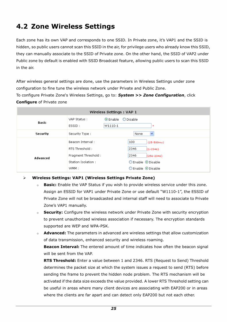
Wireless Settings: VAP1 (Wireless Settings Private Zone)
Basic: Enable the VAP Status if you wish to provide wireless service under this zone.
Assign an ESSID for VAP1 under Private Zone or use default “W1110-1”, the ESSID of
Private Zone will not be broadcasted and internal staff will need to associate to Private
Zone‟s VAP1 manually.
Security: Configure the wireless network under Private Zone with security encryption
to prevent unauthorized wireless association if necessary. The encryption standards
supported are WEP and WPA-PSK.
Advanced: The parameters in advanced are wireless settings that allow customization
of data transmission, enhanced security and wireless roaming.
Beacon Interval: The entered amount of time indicates how often the beacon signal
will be sent from the VAP.
RTS Threshold: Enter a value between 1 and 2346. RTS (Request to Send) Threshold
determines the packet size at which the system issues a request to send (RTS) before
sending the frame to prevent the hidden node problem. The RTS mechanism will be
activated if the data size exceeds the value provided. A lower RTS Threshold setting can
be useful in areas where many client devices are associating with EAP200 or in areas
where the clients are far apart and can detect only EAP200 but not each other.

26
Fragment Threshold: Enter a value between 256 and 2346. The default is 2346. A
packet size larger than this threshold will be fragmented (sent with several pieces
instead of one chunk) before transmission. A smaller value results in smaller frames but
allows a larger number of frames in transmission. A lower Fragment Threshold setting
can be useful in areas where communication is poor or disturbed by a serious amount
of radio interference.
Station Isolation: By enabling this function, all stations wirelessly associated to this
zone are isolated from each other and can only communicate with the system.
WMM: The default is Disable. Wi-Fi Multimedia (WMM) is a Quality of Service (QoS)
feature that prioritizes wireless data packets based on four access categories: voice,
video, best effort, and background. Applications without WMM and applications that do
not require QoS are assigned to the best-effort category, which receives a lower priority
than that of voice and video. Therefore, WMM decides which data streams are more
important and assigns them a higher traffic priority. This option works with
WMM-capable clients only.
Normally we use VAP2, the VAP under Public Zone to provide wireless service to public clients in a
hotspot environment. To configure Public Zone‟s Wireless Settings, go to: System >> Zone
Configuration, click Configure of Public zone
Wireless Settings: VAP2 (Wireless Settings for Public Zone)
Basic: Enable the VAP Status if you wish to provide wireless service under this zone.
Assign an ESSID for VAP2 under Private Zone or use default “W1110-2”, the ESSID of
Private Zone will be broadcasted in default settings to allow it to be scanned in the air.
Security: Configure the wireless network under Public Zone with security encryption to
prevent unauthorized wireless association if necessary. The encryption standards
supported are WEP, 802.1X, WPA-PSK and WPA-RADIUS.
Advanced: The parameters in advanced are wireless settings that allow customization
of data transmission, enhanced security and wireless roaming.
Beacon Interval: The entered amount of time indicates how often the beacon signal

27
will be sent from the VAP.
RTS Threshold: Enter a value between 1 and 2346. RTS (Request to Send) Threshold
determines the packet size at which the system issues a request to send (RTS) before
sending the frame to prevent the hidden node problem. The RTS mechanism will be
activated if the data size exceeds the value provided. A lower RTS Threshold setting can
be useful in areas where many client devices are associating with EAP200 or in areas
where the clients are far apart and can detect only EAP200 but not each other.
Fragment Threshold: Enter a value between 256 and 2346. The default is 2346. A
packet size larger than this threshold will be fragmented (sent with several pieces
instead of one chunk) before transmission. A smaller value results in smaller frames but
allows a larger number of frames in transmission. A lower Fragment Threshold setting
can be useful in areas where communication is poor or disturbed by a serious amount
of radio interference.
Broadcast SSID: Enable to broadcast VAP2‟s SSID in the air, Disable to hide VAP‟s
SSID so that it cannot be scanned.
Station Isolation: By enabling this function, all stations wirelessly associated to this
zone are isolated from each other and can only communicate with the system.
WMM: The default is Disable. Wi-Fi Multimedia (WMM) is a Quality of Service (QoS)
feature that prioritizes wireless data packets based on four access categories: voice,
video, best effort, and background. Applications without WMM and applications that do
not require QoS are assigned to the best-effort category, which receives a lower priority
than that of voice and video. Therefore, WMM decides which data streams are more
important and assigns them a higher traffic priority. This option works with
WMM-capable clients only.
28
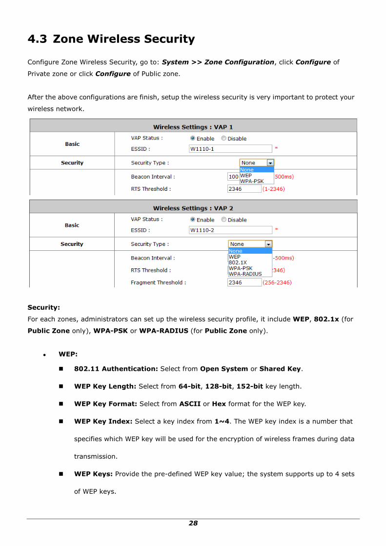
4.3 Zone Wireless Security
Configure Zone Wireless Security, go to: System >> Zone Configuration, click Configure of
Private zone or click Configure of Public zone.
After the above configurations are finish, setup the wireless security is very important to protect your
wireless network.
Security:
For each zones, administrators can set up the wireless security profile, it include WEP, 802.1x (for
Public Zone only), WPA-PSK or WPA-RADIUS (for Public Zone only).
WEP:
802.11 Authentication: Select from Open System or Shared Key.
WEP Key Length: Select from 64-bit, 128-bit, 152-bit key length.
WEP Key Format: Select from ASCII or Hex format for the WEP key.
WEP Key Index: Select a key index from 1~4. The WEP key index is a number that
specifies which WEP key will be used for the encryption of wireless frames during data
transmission.
WEP Keys: Provide the pre-defined WEP key value; the system supports up to 4 sets
of WEP keys.

29
802.1X:
Dynamic WEP: For 802.1X security type, Dynamic WEP is always enabled to
automatically generate WEP keys for encryption.
WEP Key Length: Select from 64-bit or 128-bit key length.
Re-keying Period: The time interval for the dynamic WEP key to be updated; the time
unit is in second.
WPA-PSK:
Cipher Suite: Select an encryption method from TKIP (WPA), AES (WPA), TKIP
(WAP2), AES (WAP2), or Mixed.
Pre-shared Key / Passphrase: Enter the key value for the pre-shared key or
passphrase.
Group Key Update Period: The time interval for the Group Key to be renewed; the
time unit is in seconds.
WPA-RADIUS: Same as 802.1X, when it is selected, it is combined with TKIP, AES or
Mixed mode.
Cipher Suite: Select an encryption method from TKIP (WPA), AES (WPA), TKIP(WAP2),
AES (WAP2), or Mixed.
Group Key Update Period: The time interval for the Group Key to be renewed; the
time unit is in seconds.

30
5 Who Can Access the Network
5.1 Type of Users
Configure Users, go to: Users >> Authentication.
This section is for administrators to pre-configure authentication servers for the entire system.
Concurrently up to three servers can be selected and pre-configured for static user authentication,
one server uses built-in LOCAL database while the other two servers uses external RADIUS database.
In addition, another server called On-demand can be configured for temporary user authentication.
Auth Database: There are four different authentication options in WHG-1000 that uses
databases: LOCAL, RADIUS1, RADIUS2 and ONDEMAND.
Auth Server Name: Set a name for the authentication databases by using numbers (0~9),
alphabets (a~z or A ~Z), dash (-), underline (_), space and dot (.) only. This name is used for the
administrator to identify the authentication options easily such as HQ-RADIUS.
Postfix: A postfix represents the authentication server in a complete username. For example,
user1@local means that this user (user1) will be authenticated against the LOCAL authentication
database.
Policy: Select one Policy from the drop-down list box for this specific authentication option.
Black List: There are 5 sets of black lists provided by the system. A user account listed in the
black list is not allowed to log into the system, the client's access will be denied. The administrator
may select one (or None) black list from the drop-down menu and this black list will be applied to
this specific authentication option.
Configure: Click Configure button to enter the specific authentication page. For example, if you
want to edit the Local authentication database, please click Configure button of Local.
31
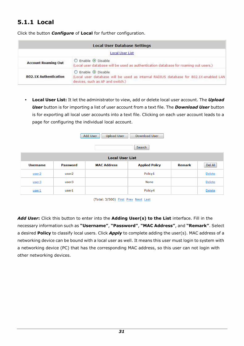
5.1.1 Local
Click the button Configure of Local for further configuration.
Local User List: It let the administrator to view, add or delete local user account. The Upload
User button is for importing a list of user account from a text file. The Download User button
is for exporting all local user accounts into a text file. Clicking on each user account leads to a
page for configuring the individual local account.
Add User: Click this button to enter into the Adding User(s) to the List interface. Fill in the
necessary information such as “Username”, “Password”, “MAC Address”, and “Remark”. Select
a desired Policy to classify local users. Click Apply to complete adding the user(s). MAC address of a
networking device can be bound with a local user as well. It means this user must login to system with
a networking device (PC) that has the corresponding MAC address, so this user can not login with
other networking devices.

32
Search: Enter a keyword of a username or remark to be searched in the text filed and click this
button to perform the search. All usernames matching the keyword will be listed.
Del All: Click on this button to delete all the users at once or click on Delete hyperlink to
delete a specific the user individually.

33
Edit User: If editing the content of individual user account is needed, click the username of the
desired user account in Local User List to enter the User Profile Interface for that particular
user, and then modify or add any desired information such as Username, Password, MAC
Address (optional), Applied Policy (optional) and Remark (optional). Click Apply to complete
the modification.

34
5.1.2 RADIUS
There are two RADIUS authentication database for configuration. Click the button Configure of any
one of RADIUS servers for further configuration. The RADIUS server sets the external authentication
for user accounts. Enter the information for the primary server and/or the secondary server (the
secondary server is not mandatory). The fields with red asterisk are necessary information. These
settings will become effective immediately after clicking the Apply button.
External RADIUS Related Settings
802.1X Authentication: Enable /Disable 802.1X authentications for users authenticating
through this Server.
Username Format: Select the format which the user login information is sent to the
external RADIUS Server. You may choose to send username in Complete (userID + Postfix),
Only ID or Leave Unmodified. Please note that if Leave Unmodified option is selected, the
system will send the username to Default Auth Server set in 802.1X configuration page
for authentication.
NAS Identifier: This attribute is the string identifying the NAS originating the access
request. System will send this value to the external RADIUS server, if the external RADIUS
server needs this.

35
NAS Port Type: Indicates the type of physical port the network access server is using to
authenticate the user. System will send this value to the external RADIUS server, if the
external RADIUS server needs this.
Class-Policy Mapping: This function is to assign a Policy to a RADIUS class attribute sent
from the RADIUS server. When the clients classified by RADIUS class attributes logs into the
system via the RADIUS server, each client will be mapped to an assigned Policy.
Primary / Secondary RADIUS Server
Server: Enter the domain name or IP address of your RADIUS Server.
Authentication Port: Enter the Port number used for authentication.
Accounting Port: Enter the Port number used for accounting.
Secret Key: Secret Key used for authentication.
Accounting Service: Enable / Disable RADIUS accounting.
Authentication Protocol: Select Challenge-Handshake Authentication Protocol (CHAP) or
Password Authentication Protocol (PAP).
36
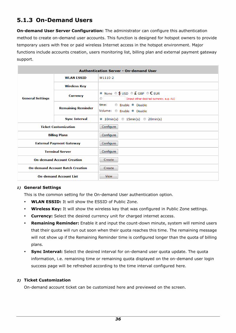
5.1.3 On-Demand Users
On-demand User Server Configuration: The administrator can configure this authentication
method to create on-demand user accounts. This function is designed for hotspot owners to provide
temporary users with free or paid wireless Internet access in the hotspot environment. Major
functions include accounts creation, users monitoring list, billing plan and external payment gateway
support.
1) General Settings
This is the common setting for the On-demand User authentication option.
WLAN ESSID: It will show the ESSID of Public Zone.
Wireless Key: It will show the wireless key that was configured in Public Zone settings.
Currency: Select the desired currency unit for charged internet access.
Remaining Reminder: Enable it and input the count-down minute, system will remind users
that their quota will run out soon when their quota reaches this time. The remaining message
will not show up if the Remaining Reminder time is configured longer than the quota of billing
plans.
Sync Interval: Select the desired interval for on-demand user quota update. The quota
information, i.e. remaining time or remaining quota displayed on the on-demand user login
success page will be refreshed according to the time interval configured here.
2) Ticket Customization
On-demand account ticket can be customized here and previewed on the screen.

37
Receipt Header: There are 3 receipt headers supported by the system. The entered content
will be printed on the receipt. These headers are optional.
Receipt Footer: There are 3 receipt footers supported by the system. The entered content will
be printed on the receipt. These footers are optional.
Remark: Enter any additional information that will appear at the bottom of the receipt.
Background Image: You can choose to customize the ticket by uploading your own
background image for the ticket, or choose none. Click Edit to select the image file and then
click Upload. The background image file size limit is 100 Kbytes. No limit for the dimensions
of the image is set, but a 460x480 image is recommended.
Number of Tickets: Enable this function to print duplicate receipts. Another Remark field will
appear when the Number of Ticket is selected to 2 and the content will appear at the bottom
of the 2nd duplicate receipt.
Preview: Click Preview button, the ticket will be shown including the information of
username and password with the selected background. You can also print the ticket here.
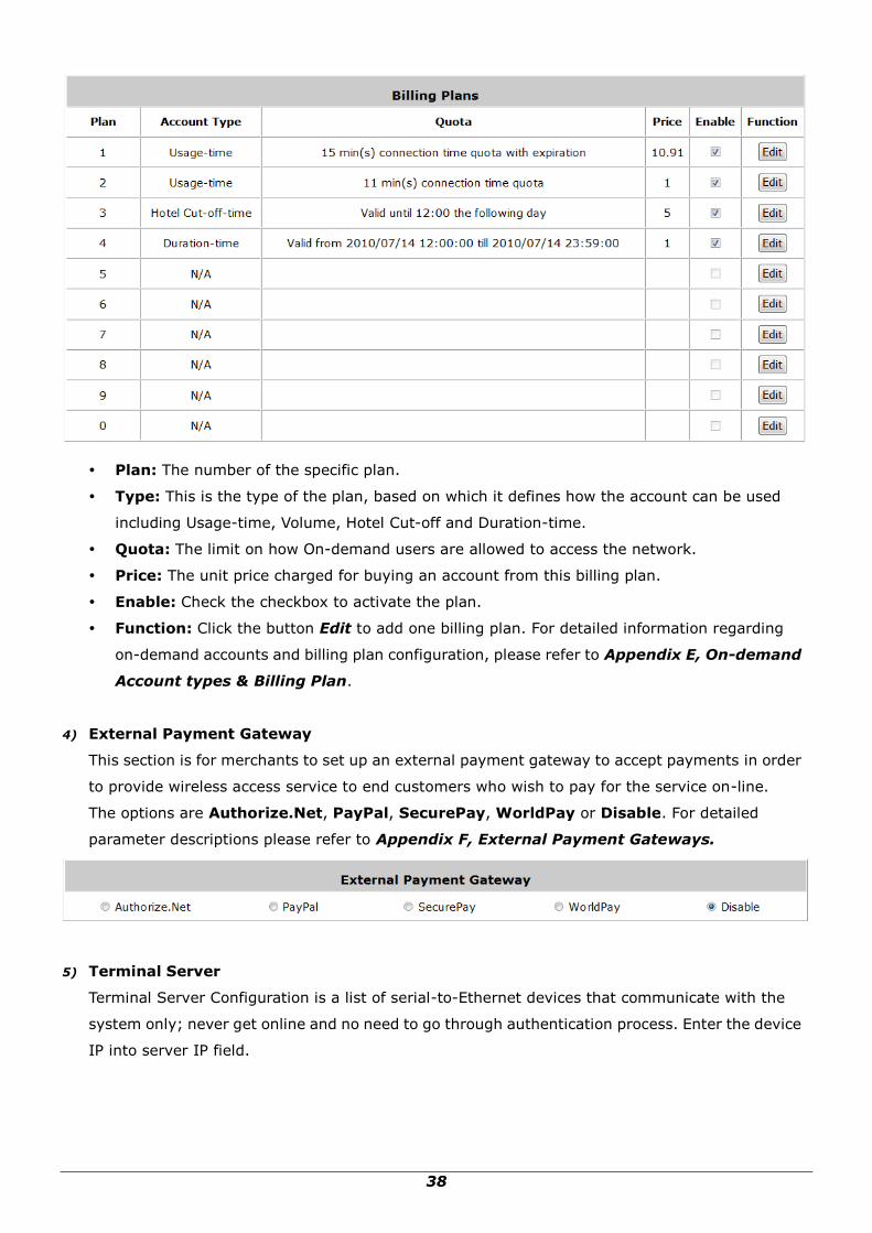
3) Billing Plans
Administrators can configure several billing plans. Click Edit button to enter the page of Editing
Billing Plan. Configure billing plans with desired account type, expiration date, price, etc. Click
Apply to save the plan. Go back to the screen of Billing Plans, check the Enable checkbox or
click Select all button, and then click Apply, the plan(s) will be activated.
38
Plan: The number of the specific plan.
Type: This is the type of the plan, based on which it defines how the account can be used
including Usage-time, Volume, Hotel Cut-off and Duration-time.
Quota: The limit on how On-demand users are allowed to access the network.
Price: The unit price charged for buying an account from this billing plan.
Enable: Check the checkbox to activate the plan.
Function: Click the button Edit to add one billing plan. For detailed information regarding
on-demand accounts and billing plan configuration, please refer to Appendix E, On-demand
Account types & Billing Plan.
4) External Payment Gateway
This section is for merchants to set up an external payment gateway to accept payments in order
to provide wireless access service to end customers who wish to pay for the service on-line.
The options are Authorize.Net, PayPal, SecurePay, WorldPay or Disable. For detailed
parameter descriptions please refer to Appendix F, External Payment Gateways.
5) Terminal Server
Terminal Server Configuration is a list of serial-to-Ethernet devices that communicate with the
system only; never get online and no need to go through authentication process. Enter the device
IP into server IP field.

39
6) On-demand Account Creation
After at least one billing plan is enabled, the administrator can generate single on-demand user
accounts here. Click this to enter the On-demand Account Creation page. Click on the Create
button of the desired plan to create an on-demand account. The username and password of to be
created on-demand account is configurable. Select Manual created in Username/Password
Creation and then administrator can enter desired username and password for the on-demand
account. In addition, an External ID such as student‟s school ID can be entered together with
account creation.
After the account is created, you can click Printout to print a receipt which will contain the
on-demand user‟s information, including the username and password to a network printer.
Moreover, you can click Send to POS to print a receipt by a POS device.
Note:
If no Billing plan is enabled, accounts cannot be created by clicking Create button. Please goes back
to Billing Plans to activate at least one Billing plan by clicking Edit button and Apply the setting to
activate the plan. The printer used by Print is a pre-configured printer connected to the
administrator‟s computer.
Plan: The number of a specific plan.
Account Type: Show account type of the plan in Usage-time. Duration-time or Hotel Cut-off.
Quota: The total time amount or period on how On-demand users are allowed to access the

40
network. For Time users, it is the total time. For Volume users, it is the total amount of traffic.
Price: For each plan, this is the unit price charged for an account.
Status: Show the status in enabled or disabled.
Function: Press Create button for the desired plan; an Creating an On-demand Account will
appear for creation.
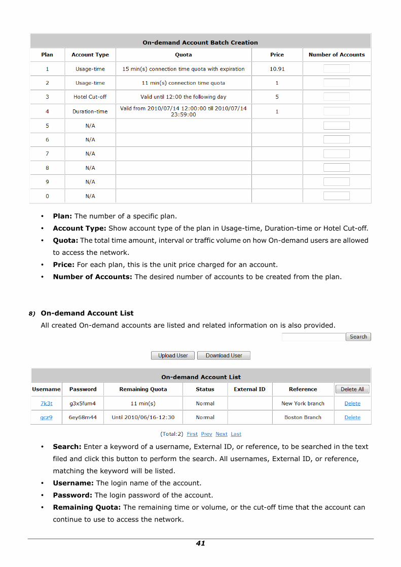
7) On-demand Account Batch Creation
After at least one billing plan is enabled, the administrator can generate multiple on-demand user
accounts at once with batch creation. Click Create button to enter the On-demand Account Batch
Creation. Enter the desired number of accounts of enabled plans to create a batch of on-demand
accounts together. The Number of Accounts field of disabled plans will not be able to enter any
number. The sum of all Number of Accounts will be constrained and will not accept a number over
the available account limits in database. Click Create button to start batch creation. Next page will
show Success or Failed message to indicate the batch creation status. Once creation is successful,
all created accounts can be exported to a text file for extended usage. Moreover, you can click
Send to POS to print a receipt to a POS device via Serial or Ethernet network. Please notice that
it takes time if you create lots of on-demand accounts by batch creation.
41
Plan: The number of a specific plan.
Account Type: Show account type of the plan in Usage-time, Duration-time or Hotel Cut-off.
Quota: The total time amount, interval or traffic volume on how On-demand users are allowed
to access the network.
Price: For each plan, this is the unit price charged for an account.
Number of Accounts: The desired number of accounts to be created from the plan.
8) On-demand Account List
All created On-demand accounts are listed and related information on is also provided.
Search: Enter a keyword of a username, External ID, or reference, to be searched in the text
filed and click this button to perform the search. All usernames, External ID, or reference,
matching the keyword will be listed.
Username: The login name of the account.
Password: The login password of the account.
Remaining Quota: The remaining time or volume, or the cut-off time that the account can
continue to use to access the network.
42
Status: The status of the account.
o Normal: the account is not currently in use and has not exceed the quota limit.
o Online: the account is currently in use.
o Expired: the account is not valid any more, even if there is remaining quota left.
o Out of Quota: the account has exceeded the quota limit.
o Redeemed: the account has been applied for account renewal.
External ID: This is an additional information field for combined with a unique account only,
for example the customer‟s name or social security number etc.
Reference: Any other additional information, for example venue where the account is
generated etc.
Delete All: This will delete all the users at once.
Delete: This will delete the users individually.
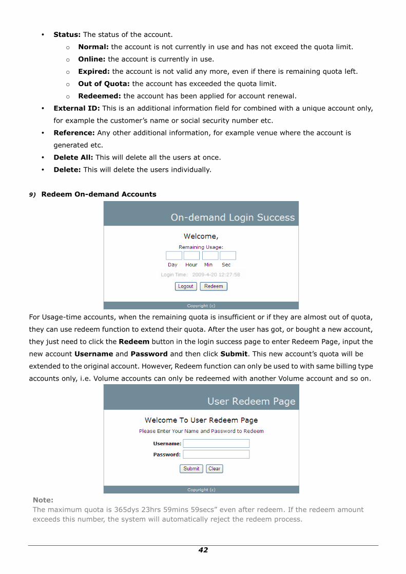
9) Redeem On-demand Accounts
For Usage-time accounts, when the remaining quota is insufficient or if they are almost out of quota,
they can use redeem function to extend their quota. After the user has got, or bought a new account,
they just need to click the Redeem button in the login success page to enter Redeem Page, input the
new account Username and Password and then click Submit. This new account‟s quota will be
extended to the original account. However, Redeem function can only be used to with same billing type
accounts only, i.e. Volume accounts can only be redeemed with another Volume account and so on.
Note:
The maximum quota is 365dys 23hrs 59mins 59secs” even after redeem. If the redeem amount
exceeds this number, the system will automatically reject the redeem process.

43
Note:
Duration-time and Hotel Cut-off type do not support redeem function.

44
5.2 User Login
5.2.1 Default Authentication
There are different types of authentication database (LOCAL, RADIUS and ONDEMAND) that are
supported by the system. Only Public Zone can set authentication.
A postfix is used to inform the system which authentication option to be used for authenticating an
account (e.g. Bob@local or Tim@radius1 etc.) when multiple options are concurrently in use. One of
the authentication options can be assigned as default. For authentication assigned as default, the
postfix can be omitted. For example, if "local" is the postfix of the default option, then user with
username Bob can login as "Bob" without having to type in "Bob@local”.
5.2.2 Login with Postfix
For each authentication option, set a postfix that is easy to distinguish (e.g. Local) user login with
which authentication server. The acceptable characters are numbers (0~9), alphabets (a~z or A~Z),
dash (-), underline (_) and dot (.) within a maximum of 40 characters. All other characters are not
allowed.
Beside the Default Authentication, all other authentication server users logging into to system, the
username must contain the postfix to identify the authentication option this user belongs to.

45
5.2.3 An Example of User Login
Normally, users will be authenticated before they get network access through WHG-1000. This section
presents the basic authentication flow for end users. Please make sure that the WHG-1000 is
configured properly and network related settings are done.
1. Open an Internet browser and try to connect to any website (in this example, we try to connect to
www.google.com).
a) For the first time, if the WHG-1000 is not using a trusted SSL certificate, there will be a
“Certificate Error”, because the browser treats WHG-1000 as an illegal website.
b) Please press “Continue to this website” to continue.
c) The default user login page will appear in the browser.
2. Enter the username and password (for example, we use a local user account: test@local here)
and then click Submit button. If the Remember Me check box is checked, the browser will store
the username and password on the current computer in order to automatically login to the system
at the next login. Then, click the Submit button.
The Credit Balance button on the User Login Page is for on-demand users only, where they can
check their Remaining quota.

46
3. Successful! The Login Success Page means you are connected to the network and Internet now!

47
6 Restrain the Users
6.1 Black List
Configure Black List, go to: Users >> Black List.
The administrator can add, delete, or edit the black list for user access control. Users‟ accounts that
appear in the black list will be denied of network access. The administrator can use the pull-down
menu to select the desired black list.
Select Black List: There are 5 black list profiles available for utilization.
Name: Set the black list name and it will show on the pull-down menu above.
Add User(s): Click the Add User(s) button to add users to the selected black list.

48
After entering the usernames in the “Username” field and the related information in the
“Remark” blank (not required), click Apply to add the users.
If removing a user from the black list is desired, select the user‟s “Delete” check box and then
click the Delete button to remove that user from the black list.
After the Black List editing is completed. You can select the Black List in each Authentication Server
to let it to become effective.

49
6.2 MAC Address Control
Configure MAC Address Control, go to: Users >> Additional Control.
MAC ACL: With this function, only the users with their MAC addresses in this list can login to
WHG-1000. There are 40 users maximum allowed in this MAC address list. User authentication is still
required for these users. Click Edit to enter the MAC Address Control list. Fill in these MAC
addresses, select Enable, and then click Apply.
Caution:
The format of the MAC address is: xx:xx:xx:xx:xx:xx or xx-xx-xx-xx-xx-xx.

50
6.3 Policy
Configure Policy, go to: Users >> Policy.
WHG-1000 supports multiple Policies, including one Global Policy and 5 individual Policy.
Global Policy is the system‟s universal policy and applied to all clients unless they are bounded by
another policy. Individual Policy can be defined and applied to different authentication server. The
client login with this authentication server will be bound by the corresponding Policy, if for a
authentication server no policy is applied, it‟s users will be governed by the Global Policy.
When the type of authentication database is RADIUS, the Class-Policy Mapping function will be
available to allow the administrator to assign a Policy for a RADIUS class attribute; therefore, a Policy
will be mapped to a user of a RADIUS class attribute.
Global Policy
Global policy is the system‟s universal policy containing Firewall Rules, Specific Routes Profile
and Maximum Concurrent Sessions which will be applied to all users unless the user has been
regulated and applied with another individual Policy.
Select Policy: Select the desired policy profile to configure.
Firewall Profile: Global policy and policy 1 ~ 5 all have a firewall service list and a set of firewall
profile which is composed of firewall rules.
Specific Route Profile: When Specific Routes are configured here, all clients applied with this
policy will access the specific destination through these gateway settings.
Maximum Concurrent Sessions: Set the maximum concurrent sessions for each client
belonging to this group.
Policy 1 ~ Policy 5
Beside Global Policy, Policy1 to Policy5, each consists of access control profiles that can be
configured respectively and applied to a certain authentication server or user.

51
Select Policy: Select the desired policy profile to configure.
Firewall Profile: Each Policy has a firewall service list and a set of firewall profile consisting of
firewall rules.
Specific Route Profile: The default gateway of a desired IP address can be defined in a policy.
When Specific Routes are configured here, all clients applied with this policy will access the specific
destination through these gateway settings.
Schedule Profile: The Schedule table in a 7X24 format is used to control the clients‟ login time.
When Schedule is enabled, clients applied with this policy are only allowed to login the system at
the time which is checked in Schedule profile settings.
QoS Profile: QoS profile defines the traffic class for the users governed by this Policy.
Maximum Concurrent Sessions: Set the maximum concurrent sessions for each client
belonging to this group.

52
6.3.1 Firewall
Firewall Profile: Click Setting for Firewall Profile. The Firewall Configuration will appear. Click
Predefined and Custom Service Protocols to edit the protocol list. Click Firewall Rules to edit the
rules.
1) Predefined Protocols
Predefined and Custom Service Protocols: There are predefined service protocols available for
firewall rules editing.
The administrator is able to add new custom service protocols by clicking Add, and delete the added
protocols individually or with Select All followed by Delete operation.
Caution:
The Predefined Service Protocols can not be deleted.
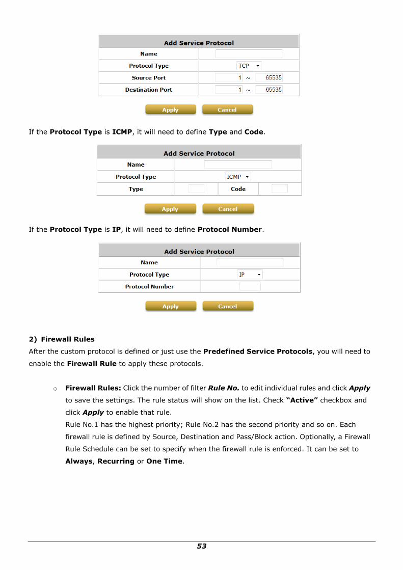
Click Add to add a custom service protocol. The Protocol Type can be defined from a list of service
by protocols (TCP/UDP/ICMP/IP); and then define the Source Port (range) and Destination Port
(range); click Apply to save this protocol.
53
If the Protocol Type is ICMP, it will need to define Type and Code.
If the Protocol Type is IP, it will need to define Protocol Number.
2) Firewall Rules
After the custom protocol is defined or just use the Predefined Service Protocols, you will need to
enable the Firewall Rule to apply these protocols.
o Firewall Rules: Click the number of filter Rule No. to edit individual rules and click Apply
to save the settings. The rule status will show on the list. Check “Active” checkbox and
click Apply to enable that rule.
Rule No.1 has the highest priority; Rule No.2 has the second priority and so on. Each
firewall rule is defined by Source, Destination and Pass/Block action. Optionally, a Firewall
Rule Schedule can be set to specify when the firewall rule is enforced. It can be set to
Always, Recurring or One Time.

54
Selecting the Filter Rule Number 1 as an example:
o Rule Number: This is the rule selected “1”. Rule No. 1 has the highest priority; rule No.
2 has the second priority, and so on.
o Rule Name: The rule name can be changed here.
o Source/Destination – Interface/Zone: There are choices of ALL, WAN, Public
and Private to be applied for the traffic interface.
o Source/Destination – IP Address/Domain Name: Enter the source and
destination IP addresses. Domain Name filtering is supported but Domain Host
filtering is not.
o Source/Destination – Subnet Mask: Select the source and destination subnet
masks.
o Source- MAC Address: The MAC Address of the source IP address. This is for specific
MAC address filter.
o Service Protocol: These are defined protocols in the service protocols list to be
selected.
o Schedule: When schedule is selected, clients assigned with this policy are applied the
firewall rule only within the time checked. There are three options, Always,
Recurring and One Time. Recurring is set with the hours within a week.
o Action for Matched Packets: There are two options, Block and Pass. Block is to
prevent packets from passing and Pass is to permit packets passing.
55
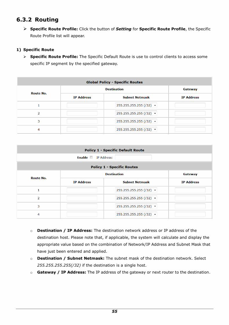
6.3.2 Routing
Specific Route Profile: Click the button of Setting for Specific Route Profile, the Specific
Route Profile list will appear.
1) Specific Route
Specific Route Profile: The Specific Default Route is use to control clients to access some
specific IP segment by the specified gateway.
o Destination / IP Address: The destination network address or IP address of the
destination host. Please note that, if applicable, the system will calculate and display the
appropriate value based on the combination of Network/IP Address and Subnet Mask that
have just been entered and applied.
o Destination / Subnet Netmask: The subnet mask of the destination network. Select
255.255.255.255(/32) if the destination is a single host.
o Gateway / IP Address: The IP address of the gateway or next router to the destination.
56
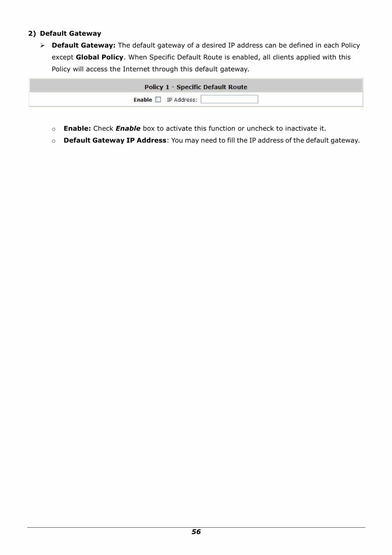
2) Default Gateway
Default Gateway: The default gateway of a desired IP address can be defined in each Policy
except Global Policy. When Specific Default Route is enabled, all clients applied with this
Policy will access the Internet through this default gateway.
o Enable: Check Enable box to activate this function or uncheck to inactivate it.
o Default Gateway IP Address: You may need to fill the IP address of the default gateway.

57
6.3.3 Schedule
Schedule Profile: Click Setting of Schedule Profile to enter the configuration page. Select
Enable to show the Permitted Login Hours list. This function is used to limit the time when
clients can log in. Check the desired time slots checkbox and click Apply to save the settings.
These settings will become effective immediately after clicking Apply.

58
6.3.4 QoS Profile
For certain applications or users that need stable bandwidth or traffic priority, Policy 1 to 5 allows
defining the QoS profile for the users governed by this Policy.
Traffic Class: A Traffic Class can be chosen for a Group of users. There are four traffic classes:
Voice, Video, Best-Effort and Background. Voice and Video traffic will be placed in the high
priority queue. When Best-Effort or Background is selected, more bandwidth management
options such as Downlink and Uplink Bandwidth will appear.
Total Downlink: Defines the maximum bandwidth allowed to be shared by clients.
Individual Maximum Downlink: Defines the maximum downlink bandwidth allowed for an
individual client. The Individual Maximum Downlink cannot exceed the value of Total Downlink.
Individual Request Downlink: Defines the guaranteed minimum downlink bandwidth allowed
for an individual client. The Individual Request Downlink cannot exceed the value of Total
Downlink and Individual Maximum Downlink.
Total Uplink: Defines the maximum uplink bandwidth allowed to be shared by clients.
Individual Maximum Uplink: Defines the maximum uplink bandwidth allowed for an individual
client. The Individual Maximum Uplink cannot exceed the value of Total Uplink.
Individual Request Uplink: Defines the guaranteed minimum bandwidth allowed for an
individual client. The Individual Request Uplink cannot exceed the value of Total Uplink and
Individual Maximum Uplink.

59
6.3.5 Session Limit
To prevent ill-behaved clients or malicious software from taking up the system‟s connection
resources, the administrator can restrict the number of concurrent sessions that a user can
establish.
The maximum number of concurrent sessions including TCP and UDP for each user can be
specified in the Global policy, which applies to authenticated users, users on a
non-authenticated port, privileged users, and clients in DMZ zones. Also this can be specified
in the other policies to apply to the authenticated users.
When the number of a user‟s sessions reaches the session limit (a choice of Unlimited, 10, 25,
50, 100, 200, 350 and 500), the user will be implicitly suspended upon receipt of any new
connection request. In this case, a record will be logged to a SYSLOG server.
Since this basic protection mechanism may not be able to protect the system from all
malicious DoS attacks, it is strongly recommended to build some immune capabilities (such
as IDS or IPS solutions) in network deployment to maintain network operation.

60
7 Access Network without Authentication
7.1 DMZ
Configure DMZ, go to: Network >> Network Address Translation >> DMZ (Demilitarized
Zone).
There are 20 sets of static Internal IP Address and External IP Address available. Enter Internal and
External IP Address as a set. After the setup, accessing the External IP address listed in DMZ will be
mapped to accessing the corresponding Internal IP Address. These settings will become effective
immediately after clicking the Apply button. The External IP Address of the Automatic WAN IP
Assignment is the IP address of External Interface (WAN) that will change dynamically if WAN
Interface is Dynamic. When Automatic WAN IP Assignments is enabled, the entered Internal IP
Address of Automatic WAN IP Assignment will be bound with WAN interface.
61
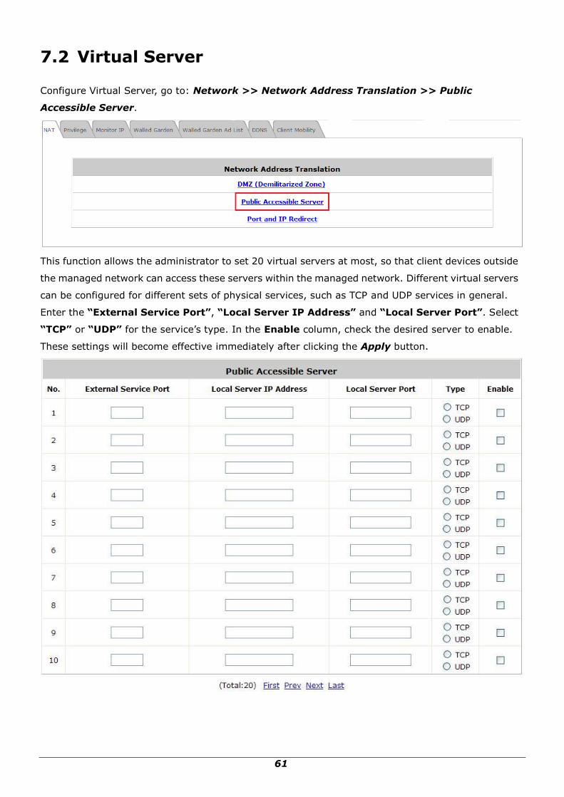
7.2 Virtual Server
Configure Virtual Server, go to: Network >> Network Address Translation >> Public
Accessible Server.
This function allows the administrator to set 20 virtual servers at most, so that client devices outside
the managed network can access these servers within the managed network. Different virtual servers
can be configured for different sets of physical services, such as TCP and UDP services in general.
Enter the “External Service Port”, “Local Server IP Address” and “Local Server Port”. Select
“TCP” or “UDP” for the service‟s type. In the Enable column, check the desired server to enable.
These settings will become effective immediately after clicking the Apply button.

62
7.3 Privilege List
Configure Privilege List, go to: Network >> Privilege
Setup the Privilege IP Address List and Privilege MAC Address List. The clients accessing the
internet via IP addresses and/or networking devices in the list can access the network without any
authentication.

63
7.3.1 Privilege IP
Privilege IP Address List
Configure Privilege IP Address List, go to: Network Configuration >> Privilege >> IP Address
List.
If there are workstations inside the managed network that need to access the network without
authentication, enter the IP addresses of these workstations in the “Granted Access by IP
Address”. The “Remark” field is not necessary but is useful to keep track. WHG-1000 allows 100
privilege IP addresses at most. These settings will become effective immediately after clicking Apply.
Caution:
Permitting specific IP addresses to have network access rights without going through standard
authentication process under Public zone may cause security problems.

64
7.3.2 Privilege MAC
Privilege MAC Address List
In addition to the Privilege IP List, MAC address List allows the MAC address of the workstations that
need to access the network without authentication to be set in the “Granted Access by MAC
Address”. WHG-1000 allows 100 privilege MAC addresses at most. When manually creating the list,
enter the MAC address (the format is xx:xx:xx:xx:xx:xx) as well as the remark (not necessary).
These settings will become effective immediately after clicking Apply.
Caution:
Permitting specific MAC addresses to have network access rights without going through standard
authentication process under Public zone may cause security problems

65
7.4 Disable Authentication in Public Zone
Configure Disable Authentication in Public Zone, go to: System >> Zones Configuration, click
Configure in Public Zone.
Authentication Required For the Zone: When it is disabled, users will not need to
authenticate before they get access to the network within Public Zone.
66
8 User Login and Logout
8.1 Before User Login
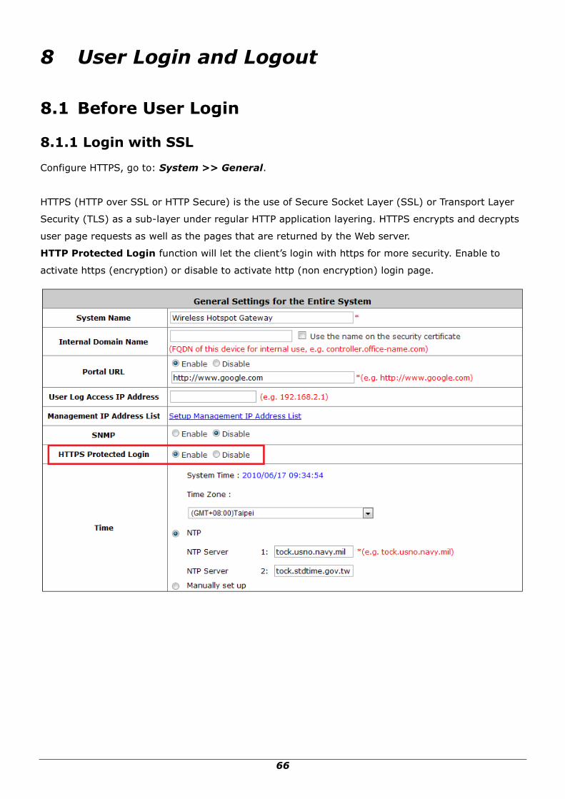
8.1.1 Login with SSL
Configure HTTPS, go to: System >> General.
HTTPS (HTTP over SSL or HTTP Secure) is the use of Secure Socket Layer (SSL) or Transport Layer
Security (TLS) as a sub-layer under regular HTTP application layering. HTTPS encrypts and decrypts
user page requests as well as the pages that are returned by the Web server.
HTTP Protected Login function will let the client‟s login with https for more security. Enable to
activate https (encryption) or disable to activate http (non encryption) login page.

67
8.1.2 Internal Domain Name with Certificate
Configure Internal Domain Name, go to: System >> General.
Internal Domain Name is the domain name of the WHG-1000 as seen on client machines connected
under zone. It must conform to FQDN (Fully-Qualified Domain Name) standard. A user on client
machine can use this domain name to access WHG-1000 instead of its IP address.
In addition, when “Use the name on the security certificate” option is checked, the system will
use the CN (Common Name) value of the uploaded SSL certificate as the domain name.
To Configure Certificate, go to: Users >> Additional Control >> Upload File.
Certificate: A data record used for authenticating network entities such as a server or a client. A
certificate contains X.509 information pieces about its owner (called the subject) and the signing
Certificate Authority (called the issuer), plus the owner's public key and the signature made by the CA.
Network entities verify these signatures using CA certificates. You can apply for a SSL certificate at
CAs such as VeriSign.
If you already have a SSL Certificate, please Click Browse to select the file and upload it. Click Apply
to complete the upload process. If you do not have a valid SSL Certificate, use the system default
certificate.
Without a valid certificate, users may encounter the following problem in IE7 when they try
to open the login page.

68
Click “Continue to this website” to access the user login page.
Use Default Certificate: Click Use Default Certificate to use the default certificate and key. Click
restart to validate the changes.

69
8.1.3 Walled Garden
Configure Walled Garden, go to: Network >> Walled Garden.
This function provides certain free services for users to access the websites listed here before login
and authentication. Up to 20 addresses or domain names of the websites can be defined in this list.
Users without the network access right can still have a chance to experience the actual network
service free of charge. Enter the website IP Address or Domain Name in the list and click Apply to
save the settings.

70
8.1.4 Walled Garden AD List
Configure Walled Garden AD List, go to: Network >> Walled Garden AD List.
This function provides advertisement links to web pages for users to access free of charge before login
and authentication. Advertisement hyperlinks are displayed on the user‟s login page. Clients who click
on it will be redirected to the listed advertisement websites.
Enter all items or make changes, click Apply, the items will be added and shown in the list.
URL: Enter the URL of the advertisement website.
Topic: Enter the content of the hyperlink, for instance if you enter Google in this field, on the user
login page a hyperlink Google will be displayed.
Description: Any additional message for administrator‟s reference.
Display: Choose Display to display advertisement hyperlinks on the login pages

71
8.2 After User Login
8.2.1 Portal URL after successful login
Configure Portal URL after a successful user login, go to: System >> General.
When this function is enabled, enter the URL of a Web server as the Portal page. Once logged in
successfully, users will be directed to this URL, such as http://www.google.com, regardless of the
original homepage set in their browsers.
When this function is disabled, after users logged in successfully, users will be directed to the original
homepage set in their browsers.

72
8.2.2 Idle Timer
Configure Idle Timer, go to: Users >> Additional Control.
If a user has idled with no network activities, the system will automatically kick out the user. The
logout timer can be set between 1~1440 minutes, and the default idle time is 10 minutes.

73
8.2.3 Multiple Login
Configure Multiple Login, go to: Users >> Additional Control.
When enabled, a user can log in from different computers with the same account. (This function
doesn‟t support On-demand users and RADIUS authentication.)

74
9 Networking Features of a Gateway
9.1 IP Plug and Play
Configure IP Plug and Play, go to: Network >> Client Mobility.
WHG-1000 supports IP PNP function. User can login and access network with any IP address setting.
This function is disabled in default settings.
When IP PNP is enabled, at the user end, a static IP address can be used to connect to the system.
Regardless of what the IP address at the user end is using, authentication can still be performed
through WHG-1000.
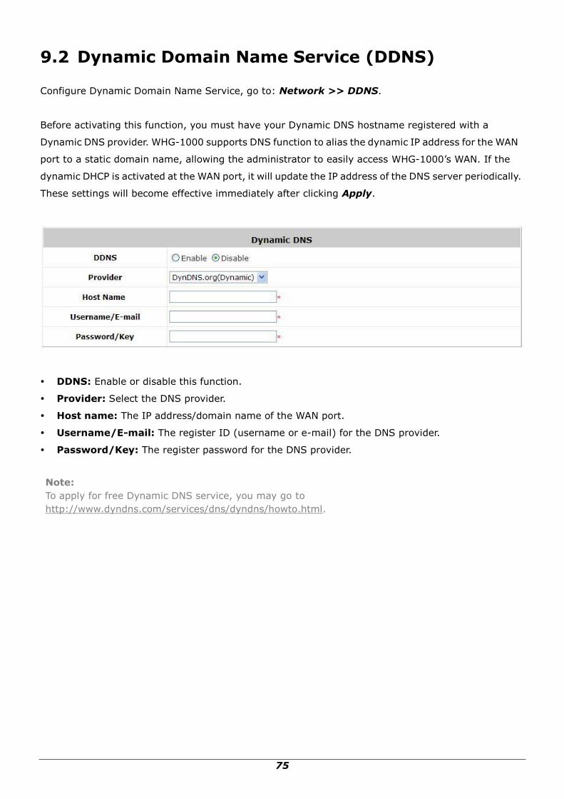
75
9.2 Dynamic Domain Name Service (DDNS)
Configure Dynamic Domain Name Service, go to: Network >> DDNS.
Before activating this function, you must have your Dynamic DNS hostname registered with a
Dynamic DNS provider. WHG-1000 supports DNS function to alias the dynamic IP address for the WAN
port to a static domain name, allowing the administrator to easily access WHG-1000‟s WAN. If the
dynamic DHCP is activated at the WAN port, it will update the IP address of the DNS server periodically.
These settings will become effective immediately after clicking Apply.
DDNS: Enable or disable this function.
Provider: Select the DNS provider.
Host name: The IP address/domain name of the WAN port.
Username/E-mail: The register ID (username or e-mail) for the DNS provider.
Password/Key: The register password for the DNS provider.
Note:
To apply for free Dynamic DNS service, you may go to
http://www.dyndns.com/services/dns/dyndns/howto.html.

76
9.3 Port and IP Redirect
Configure Port and IP Redirect, go to: Network >> NAT >> Port and IP Redirect.
This function allows the administrator to set 40 sets of the IP addresses at most for redirection
purpose. When the user attempts to connect to a destination IP address listed here, the connection
packet will be converted and redirected to the corresponding destination. Please enter the “IP
Address” and “Port” of Destination, and the “IP Address” and “Port” of Translated to
Destination. Select “TCP” or “UDP” for the service‟s type. These settings will become effective
immediately after clicking Apply.

77
10 System Management and Utilities
10.1 System Time
Configure System Time, go to: System >> General.
NTP (Network Time Protocol) communication protocol can be used to synchronize the system time
with remote time server. Please specify the local time zone and the IP address of at least one NTP
server for adjusting the time automatically (Universal Time is Greenwich Mean Time, GMT).
Manually set up is another option to setup system time, if you choose to setup system time manually,
please enter the Year, Month, Day, the current time and click Apply to activate the changes.
Note:
When system can not sync the time with NTP server, all clients will not allow to login to system.
Also on-demand accounts cannot be created.

78
10.2 Management IP
Configure Management IP, go to: System >> General.
Only PCs within the Management IP range on the list are allowed to access the system's web
management interface. For example, 10.2.3.0/24 means that as long as an administrator is using a
computer with the IP address range of 10.2.3.0/24, he or she can access the web management page.
Another example is 10.0.0.3: if an administrator is using a computer with the IP address of 10.0.0.3,
he or she can access the web management page.
The default value is “0.0.0.0/0.0.0.0”. It means that the WMI can be accessed by any IP address, for
security consideration; please change this value before the system provides service.

79
10.3 User Log Access IP Address
Configure User Log Access IP History, go to: System >> General.
Specify an IP address of the administrator‟s computer or a billing system to get billing history
information of WHG-1000 with the predefined URLs. The file name format is “yyyy-mm-dd”. An
example is provided as follows:
Traffic History:https://10.2.3.213/status/history/2005-02-17
On-demand History:https://10.2.3.213/status/ondemand_history/2005-02-17

80
10.4 SNMP
Configure SNMP, go to: System >> General. WHG-1000 supports SNMP v1/v2c.
If this function is enabled, the SNMP Management IP and the Community string can be assigned for
SNMP access to the system.

81
10.5 Three-Level Administration
WHG-1000 supports three kinds of account interface. You can log in as admin, manager or operator.
The default usernames and passwords show as follows:
Admin: The administrator can access all configuration pages of WHG-1000.
Username: admin
Password: admin
After a successful login to WHG-1000, a web management interface with a Home manual will
appear.

82
Manager: The manager can only access the configuration pages under User Authentication to
manage the user accounts.
User Name: manager
Password: manager
Operator: The operator can only access the configuration page of Create On-demand User to
create new on-demand user accounts and print out the on-demand user account receipts.
User Name: operator
Password: operator
Note:
To logout, simply click the Logout icon on the upper right corner of the interface to return to the
login screen.

83
10.6 Change Password
Configure Change Password, go to: Utilities >> Password Change.
There are three levels of authorities: admin, manager or operator. The default usernames and
passwords are as follows:
Admin: The administrator can access all configuration pages of WHG-1000.
User Name: admin
Password: admin
Manager: The manager can only access the configuration pages under User Authentication to
manage the user accounts.
User Name: manager
Password: manager
Operator: The operator can only access the configuration page of Create On-demand User to
create new on-demand user accounts and print out the on-demand user account receipts.
User Name: operator
Password: operator
The administrator can change the passwords here. Click Apply to activate this new password.
Note:
Only login with admin can change password.

84
Caution:
If the administrator’s password is lost, the administrator’s password still can be changed through the
text mode management interface via the serial console port.

85
10.7 Backup / Restore and Reset to Factory
Configure Backup / Restore and Reset to Factory Default, go to: Utilities >> Backup & Restore.
This function is used to backup/restore the WHG-1000 settings. Also, WHG-1000 can be restored to
the factory default settings here.
Backup System Settings: Click Backup to create a .db database backup file and save it on disk.
Restore System Settings: Click Browse to search for a .db database backup file created by
WHG-1000 and click Restore to restore to the same settings at the time when the backup file was
saved.
Reset to Factory Default: Click Reset to load the factory default settings of WHG-1000.
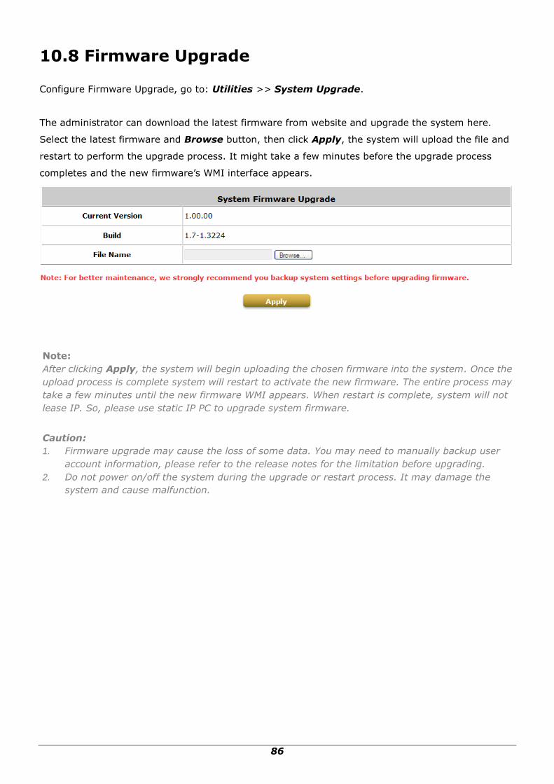
86
10.8 Firmware Upgrade
Configure Firmware Upgrade, go to: Utilities >> System Upgrade.
The administrator can download the latest firmware from website and upgrade the system here.
Select the latest firmware and Browse button, then click Apply, the system will upload the file and
restart to perform the upgrade process. It might take a few minutes before the upgrade process
completes and the new firmware‟s WMI interface appears.
Note:
After clicking Apply, the system will begin uploading the chosen firmware into the system. Once the
upload process is complete system will restart to activate the new firmware. The entire process may
take a few minutes until the new firmware WMI appears. When restart is complete, system will not
lease IP. So, please use static IP PC to upgrade system firmware.
Caution:
1. Firmware upgrade may cause the loss of some data. You may need to manually backup user
account information, please refer to the release notes for the limitation before upgrading.
2. Do not power on/off the system during the upgrade or restart process. It may damage the
system and cause malfunction.
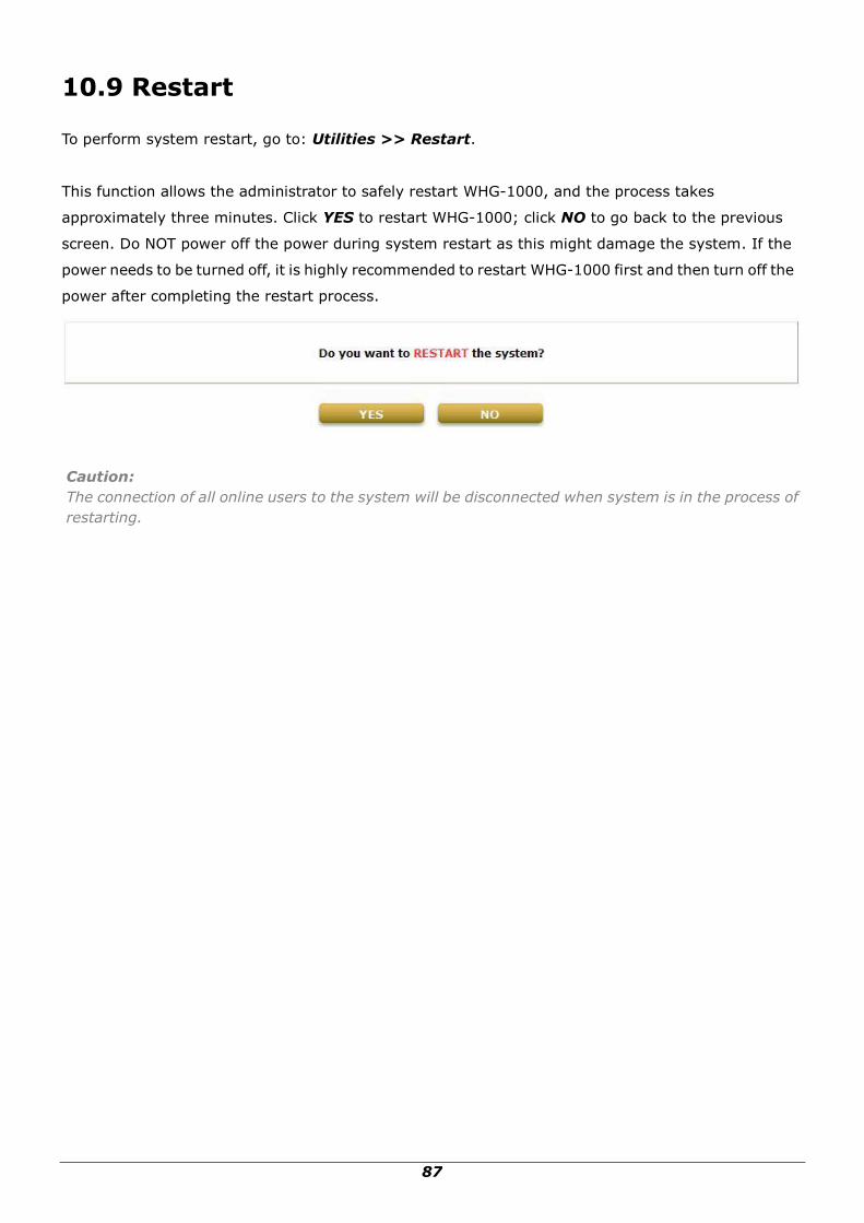
87
10.9 Restart
To perform system restart, go to: Utilities >> Restart.
This function allows the administrator to safely restart WHG-1000, and the process takes
approximately three minutes. Click YES to restart WHG-1000; click NO to go back to the previous
screen. Do NOT power off the power during system restart as this might damage the system. If the
power needs to be turned off, it is highly recommended to restart WHG-1000 first and then turn off the
power after completing the restart process.
Caution:
The connection of all online users to the system will be disconnected when system is in the process of
restarting.

88
10.10 Network Utility
Configure Network Utility, go to: Utilities >> Network Utilities.
System provide some network utilities to allow administrators to use.
Wake-on-LAN is for waking up remote devices that supports Wake-on-LAN feature by entering the
MAC address of the target device and then press Wake Up button.
Ping is to see whether a destination host is reachable and alive by entering the destination host‟s
domain name or IP address and then press Ping button.
Trace Route display the actual route taken to reach the destination host by entering the destination
host‟s domain name or IP address and then press Start button.
ARP Table for displaying ARP information stored on the system.
10.10.1 Wake-on-LAN
It allows the system to remotely boot up a power-down computer with Wake-On-LAN feature enabled
in it‟s BIOS and it is connect to LAN port. Enter the MAC Address of the desired device and click Wake
Up button to execute this function.
10.10.2 Ping
It allows administrator to detect a device using IP address or Host domain name to see if it is alive or
not.
89
10.10.3 Trace Route
It allows administrator to find out the real path of packets from the gateway to a destination using IP
address or Host domain name.
10.10.4 Show ARP Table
It allows administrator to view the IP-to-Physical address translation tables used by address
resolution protocol (ARP).

90
10.11 Monitor IP Link
Configure Monitor IP Link, go to: Network >> Monitor IP.
WHG-1000 will send out a packet periodically to monitor the connection status of the IP addresses on
the list. On each monitored item with a WEB server running, administrators may add a link for the
easy access by entering the IP, select the Protocol to http or https and then click Create. After
clicking Create button, the IP address will become a hyperlink, and administrators can easily access
the host by clicking the hyperlink remotely. Click the Delete button to remove the hyperlink if desired.

91
10.12 Console Interface
Via the console port, administrators can enter the console interface for handling problems and
situations occurred during operation.
1. In order to connect to the console port of WHG-1000, a console, modem cable and a terminal
simulation program, such as the Hyper Terminal are needed.
2. If a Hyper Terminal is used, please set the parameters as 9600, 8, None, 1, None.
Caution:
The main console is a menu-driven text interface with dialog boxes. Please use arrow keys on the
keyboard to browse the menu and press the Enter key to make selection or confirm what you enter.
3. Once the console port of WHG-1000 is connected properly, the console main screen will appear
automatically. If the screen does not appear in the terminal simulation program automatically,
please try to press the arrow keys, so that the terminal simulation program will send some
messages to the system, and the welcome screen or main menu should appear. If the welcome
screen or main menu of the console still does not pop up, please check the connection of the cables
and the settings of the terminal simulation program.
Utilities for network debugging
The console interface provides several utilities to assist the Administrator to check the
system conditions and to debug any problems. The utilities are described as follows:
Ping host (IP): By sending ICMP echo request to a specified host and wait for the
response to test the network status.
Trace routing path: Trace and inquire the routing path to a specific target.

92
Display interface settings: It displays the information of each network interface setting
including the MAC address, IP address, and Netmask.
Display the routing table: The internal routing table of the system is displayed, which
may help to confirm the Static Route settings.
Display ARP table: The internal ARP table of the system is displayed.
Display system up time: The system live time (time for system being turn on) is
displayed.
Check service status: Check and display the status of the system.
Set device into “safe mode”: If the administrator is unable to use Web Management
Interface via browser for the system failed inexplicitly. The administrator can choose
this utility and set it into safe mode, which enables him to manage this device with
browser again.
Synchronize clock with NTP server: Immediately synchronize the clock through the NTP
protocol and the specified network time server. Since this interface does not support
manual setup for its internal clock, therefore we must reset the internal clock through
the NTP.
Print the kernel ring buffer: It is used to examine or control the kernel ring buffer. The
program helps users to print out their boot-up messages instead of copying the
messages by hand.
Main menu: Go back to the main menu.
Change admin password
Besides supporting the use of console management interface through the connection of null
modem, the system also supports the SSH online connection for the setup. When using a
null modem to connect to the system console, we do not need to enter administrator‟s
password to enter the console management interface. But connecting the system by SSH,
we have to enter the username and password.
The username is “admin” and the default password is also “admin”, which is the same as for
the web management interface. Password can also be changed here. If administrators forget
the password and are unable to log in the management interface from the web or the remote
end of the SSH, they can still use the null modem to connect the console management
interface and set the administrator‟s password again.

93
Caution:
Although it does not require a username and password for the connection via the serial port, the same
management interface can be accessed via SSH. Therefore, we recommend you to immediately
change the WHG-1000 Admin username and password after logging in the system for the first time.
Reload factory default
Choosing this option will reset the system configuration to the factory defaults.
Restart WHG-1000
Choosing this option will restart WHG-1000.
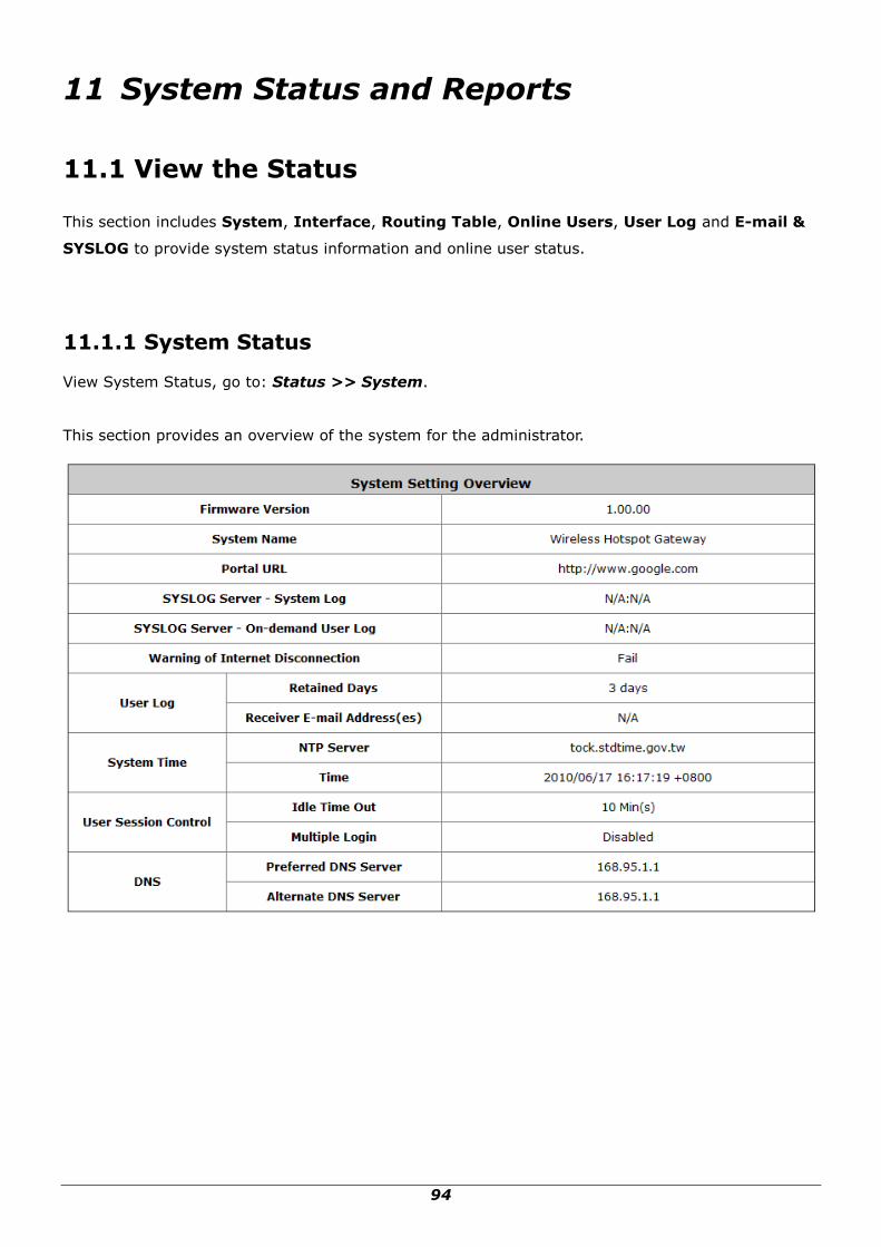
94
11 System Status and Reports
11.1 View the Status
This section includes System, Interface, Routing Table, Online Users, User Log and E-mail &
SYSLOG to provide system status information and online user status.
11.1.1 System Status
View System Status, go to: Status >> System.
This section provides an overview of the system for the administrator.

95
The description of the above-mentioned table is as follows:
Item Description
Firmware Version The present firmware version of WHG-1000
System Name The system name. The default is WHG-1000
Portal URL The page the users are directed to after initial login success.
SYSLOG server- System Log The IP address and port number of the external SYSLOG Server.
N/A means that it is not configured.
SYSLOG server- On-demand
Users Log
The IP address and port number of the external SYSLOG Server.
N/A means that it is not configured.
Warning of Internet
Disconnection
Show the status for the connection at WAN is normal or abnormal
(Internet Connection Detection) and all online users are
allowed/disallowed to log in the network.
User Log
Retained
Days
The maximum number of days for the system to retain the users‟
information.
Receiver
Address (es)
The email address to which the user log information will be set.
System Time
NTP Server The network time server that the system is set to align.
Time The system time is shown as the local time.
User Session
Control
Idle Time Out The minutes allowed for the users to be inactive before their account
expires automatically.
Multiple
Login
Enabled/disabled stands for the current setting to allow/disallow
multiple login from the same local account.
DNS
Preferred
DNS Server IP address of the preferred DNS Server.
Alternate
DNS Server IP address of the alternate DNS Server.

96
11.1.2 Interface Status
View Interface Status, go to: Status >> Interface.
This section provides an overview of the interface for the administrator including WAN, Zone
Wireless General Settings, Zone - Private and Zone - Public.

97
The description of the above-mentioned table is as follows:
Item Description
WAN
MAC Address The MAC address of the WAN port.
IP Address The IP address of the WAN port.
Subnet Mask The Subnet Mask of the WAN port.
Packets Out/In
The total accumulated packets in/out through this WAN port since
the gateway boots up. The delta shows the difference between the
numbers from last time this Interface Status page is visited.
Bytes Out/In
The total accumulated bytes in/out through this WAN port since the
gateway boots up. The delta shows the difference between the
numbers from last time this Interface Status page is visited.
Number of Sessions The sessions of WAN port.
Zone Wireless
General
Settings
MAC Address The MAC address of the Wireless.
Band The current Band setting of Wireless.
Channel The current Channel setting of Wireless.
Transmit Power The current Transmit Power setting of Wireless.
Zone - General
Mode The operation mode of the zone.
MAC Address The MAC address of the zone.
IP Address The IP address of the zone.
Subnet Mask The Subnet Mask of the zone.
Zone - DHCP
Status Enable/disable stands for status of the DHCP server in this zone
WINS IP Address The WINS server IP on DHCP server. N/A means that it is not
configured.
Start IP Address The start IP address of the DHCP IP range.
End IP address The end IP address of the DHCP IP range.
Lease Time Minutes of the lease time of the IP address.
Zone - VAP
BSSID The BSSID of this zone.
ESSID The ESSID of this zone.
Security Type The current security type of this zone.
Associated Clients The number of associated clients in this zone.

98
11.1.3 Routing Table
View System Status, go to: Status >> Routing Table.
All the Policy Route rules and Global Policy Route rules will be listed here. Also it will show the
System Route rules specified by each interface.
Policy 1~5: Shows the information of the individual Policy from 1 to 5.
Global Policy: Shows the information of the Global Policy.
System: Shows the information of the system administration.
Destination: The Destination IP address.
Subnet Mask: The Subnet Mask of the IP address range.
Gateway: The Gateway IP address of the interface.
Interface: Including WAN, Private and Public.

99
11.1.4 Current Users
View Current Users, go to: Status >> Online Users.
In this page, each online user‟s information including Username, IP Address, MAC Address, Pkts
In, Bytes In, Pkts Out, Bytes Out, Idle and Kick Out will be shown. Administrators can force out
a specific online user by clicking the hyperlink of Kick Out. Click Refresh to update the current users
list.

100
11.1.5 User Log
View User Log, go to: Status >> User Log.
This page is used to check the traffic history of WHG-1000. The history of each day will be saved
separately in the DRAM for at least 3 days (72 full hours). The system also keeps a cumulated record
of the traffic data generated by each user in the last 2 calendar months.
Caution: Since the history is saved in the DRAM, if you need to restart the system, and at the same time, keep the history, please manually copy and save the traffic history information before restarting.
If the Receiver E-mail Address(es) has been entered under the E-mail & SYSLOG page, the
system will automatically send out these history information to that specified email address.
Primary User Log
All user activities occur on the system within the nearest 72 hours excluding other user logs such
as on-demand user log are recorded; in date and time order. Each line is a traffic history record
consisting of 9 fields, Date, Type, Name, IP, MAC, Pkts In, Bytes In, Pkts Out and Bytes Out
of the user activities.
On-demand User Log
Each line is a on-demand user log record consisting of 14 fields, Date, System Name, Type,
Name, IP, MAC, Pkts In, Bytes In, Pkts Out, Bytes Out, Activation Time, 1st Login

101
Expiration Time, and Remark, of on-demand user activities.
Roaming Out User Log
Each line is a roaming out traffic history record consisting of 14 fields, Date, Type, Name, NSID,
NASIP, NASPort, UserMAC, SessionID, SessionTime, Bytes in, Bytes Out, Pkts In, Pkts
Out and Message, of user activities.
Roaming In User Log
Each line is a roaming in traffic history record consisting of 15 fields, Date, Type, Name, NSID,
NASIP, NASPort, UserMAC, UserIP, SessionID, SessionTime, Bytes in, Bytes Out, Pkts In,
Pkts Out and Message, of user activities.

102
11.1.6 Local User Monthly Network
View Local User Monthly Network Usage, go to: Status >> User Log.
Monthly Network Usage of Local User
The system keeps a cumulated record of the traffic data generated by each Local user in the latest
2 calendar months. Each line in a monthly network usage of local user record consists of 6 fields,
Username, Connection Time Usage, Packets In, Bytes In, Packets Out and Bytes Out of
user activities.
o Username: Username of the local user account.
o Connection Time Usage: The total time used by the user.
o Pkts In/ Pkts Out: The total number of packets received and sent by the user.
o Bytes In/ Bytes Out: The total number of bytes received and sent by the user.
Download Monthly Network Usage of Local User: Click on the Download button for
outputting the report manually to a local database.
A warning message will then appear. Click Save to download the record into .txt format.

103
11.2 Notification
Configure Notification, go to: Status >> E-mail & SYSLOG.
WHG-1000 can automatically send the notification of Monitor IP Report, Users Log and Session
Log to up to 3 particular e-mail addresses. A trial email is provided by the system for validation.
Secondly, the system supports recording of System Log, On-demand Users Log and Session Log
via external SYSLOG servers and sending Session Log to an external FTP server. In addition, system
Event Log of clients associated and disassociated messages appear on WMI as well.

104
11.2.1 E-Mail
Configure Notification, go to: Status >> E-mail & SYSLOG.
Notification E-mail Settings:
Receiver Email Address (es): Up to 3 e-mail address can be set up to receive the notification.
These are the receiver‟s e-mail addresses. There are four kinds of notification to selection --
Monitor IP Report, Users Log, On-demand Users Log and Session Log, and check which type of
notification to be sent.
Interval: The time interval to send the e-mail report.
SMTP Setting Test: To test the settings immediately.
Sender Email Address: The e-mail address of the administrator in charge of the monitoring.
This will show up as the sender‟s e-mail.
SMTP Server: The IP address of the sender‟s SMTP server.
SMTP Auth Method: The system provides four authentication methods, Plain, Login,
CRAM-MD5 and NTLMv1, or “None” to use none of the above. Depending on which
authentication method selected, enter the Account Name, Password and Domain.
o NTLMv1 is not currently available for general use.
o Plain and CRAM-MD5 are standardized authentication mechanisms while Login and
NTLMv1 are Microsoft proprietary mechanisms. Only Plain and Login can use the
UNIX login password. Netscape uses Plain. Outlook and Outlook express use Login as
default, although they can be set to use NTLMv1.
o Pegasus uses CRAM-MD5 or Login but which method to be used can not be
configured.

105
11.2.2 SYSLOG
SYSLOG Server Settings: There are 3 types of SYSLOG supported: System Log, On-demand
User Log, and Session Log. Enter the IP address and Port number to specify which and from
where the report should be sent to.
Note:
When the number of a user‟s session (TCP and UDP) reaches the session limit specified in the policy,
a record will be logged to this SYSLOG server.
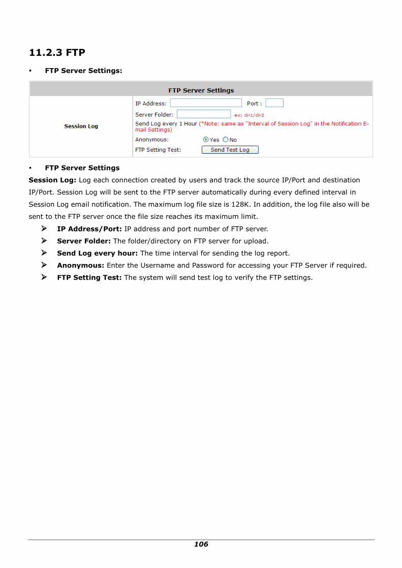
106
11.2.3 FTP
FTP Server Settings:
FTP Server Settings
Session Log: Log each connection created by users and track the source IP/Port and destination
IP/Port. Session Log will be sent to the FTP server automatically during every defined interval in
Session Log email notification. The maximum log file size is 128K. In addition, the log file also will be
sent to the FTP server once the file size reaches its maximum limit.
IP Address/Port: IP address and port number of FTP server.
Server Folder: The folder/directory on FTP server for upload.
Send Log every hour: The time interval for sending the log report.
Anonymous: Enter the Username and Password for accessing your FTP Server if required.
FTP Setting Test: The system will send test log to verify the FTP settings.

107
11.2.4 Event Log
Event Log: The Event Log provides the system activities records. The administrator can monitor the
system status by checking this log.
In the log, normally, each line represents an event record which includes these fields:
Date/Time: The time & date when the event happened
Hostname: Indicate which host records this event. Note that all events in this page are local
event, so the hostname in this field are all the same.
Process name: Indicate the event generated by the running instance.
Description: Description of this event.
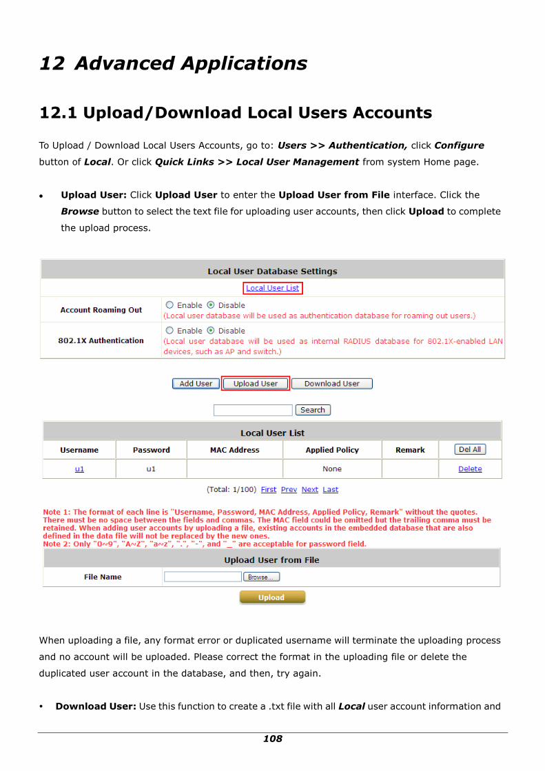
108
12 Advanced Applications
12.1 Upload/Download Local Users Accounts
To Upload / Download Local Users Accounts, go to: Users >> Authentication, click Configure
button of Local. Or click Quick Links >> Local User Management from system Home page.
Upload User: Click Upload User to enter the Upload User from File interface. Click the
Browse button to select the text file for uploading user accounts, then click Upload to complete
the upload process.
When uploading a file, any format error or duplicated username will terminate the uploading process
and no account will be uploaded. Please correct the format in the uploading file or delete the
duplicated user account in the database, and then, try again.
Download User: Use this function to create a .txt file with all Local user account information and
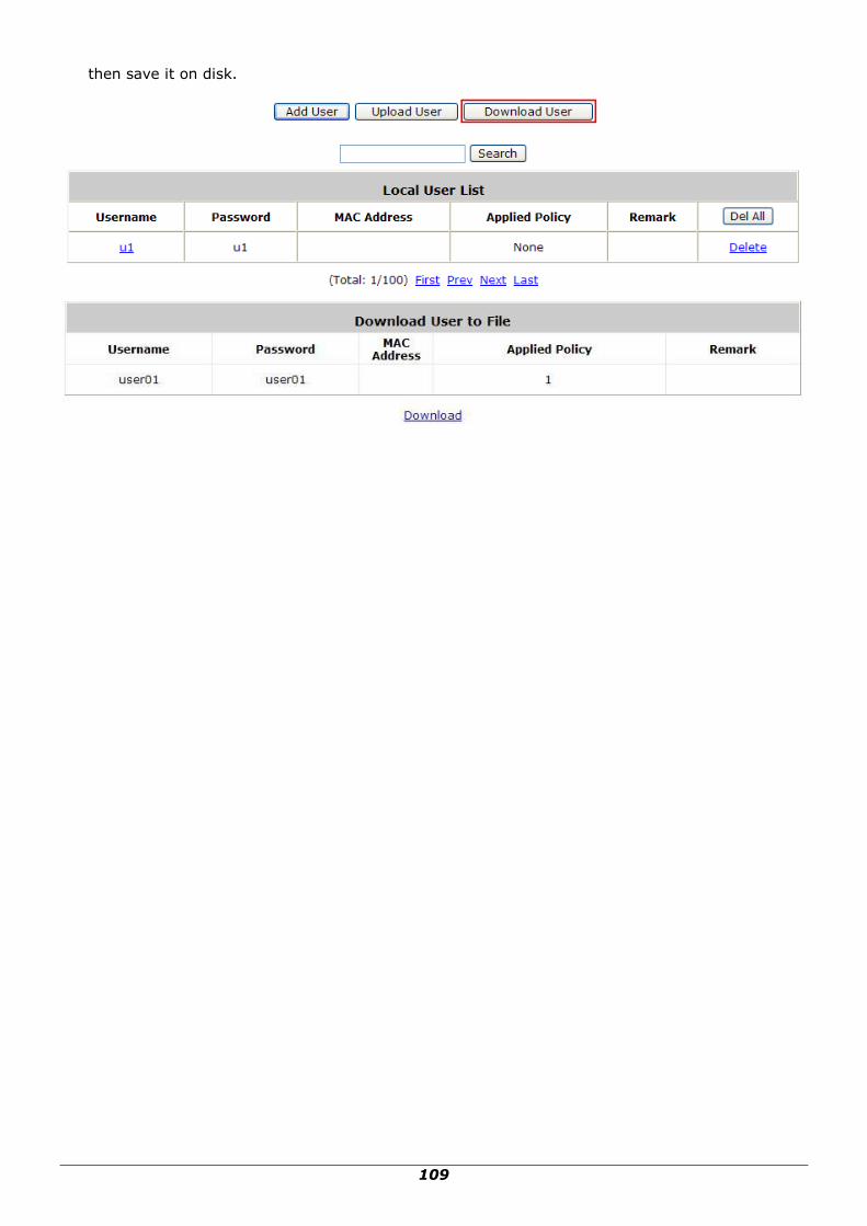
109
then save it on disk.

110
12.2 RADIUS Advanced Settings
Configure RADIUS Advanced Settings, go to: Users >> Authentication. Click Configure of
RADIUS.
Complete vs. Only ID
For RADIUS authentication, there is an option to send the complete username with postfix or
username only.
Username Format: When Complete option is checked, both the username and postfix will be
transferred to the RADIUS server for authentication. On the other hand, when Only ID option is
checked, only the username will be transferred to the external RADIUS server for authentication.
NAS Identifier
System will send this value to the external RADIUS server, if the external RADIUS server needs this.
NAS Port Type
System will send this value to the external RADIUS server, if the external RADIUS server needs this.
Class-Policy Mapping
This function is to assign a Policy to a RADIUS class attribute sent from the RADIUS server. When the
clients classified by RADIUS class attributes log into the system via the RADIUS server, each client will
be mapped to its assigned Policy.

111
12.3 Roaming Out
Configure local user Roaming Out, go to: Users >> Authentication, click configure of Local.
Under certain configurations, WHG-1000 can act as a RADIUS server for Roaming Out local user
logged from other system. The Local User database will act as the RADIUS user database.
Account Roaming Out & 802.1X Authentication: When Account Roaming Out is enabled;
the link of Roaming Out & 802.1X Client Device Settings will be available to define the client
device authorized to roam by entering the IP address, Subnet Mask, and Secret Key.
Click the hyperlink Roaming Out & 802.1x Client Device Settings to enter the Roaming Out
& 802.1X Client Device Settings interface. Choose Roaming Out and key in the Roaming Out
client‟s IP address and network mask and then click Apply to complete the settings.
In the other system, such as another WHG-1000, setup it‟s RADIUS server to this WHG-1000
with same postfix, then the local user in this WHG-1000 can login success from another
WHG-1000 by RADIUS authentication.

112
12.4 Customizable Pages
Configure Custom Pages, go to: System >> Zone Configuration, click Configure in Public zone.
There are several user login and logout pages that can be customized by the administrator.
You can select Template Page or External Page.
Template Page:
To utilize the template user pages stored locally in the system, choose Template Page and
configure the necessary settings as follows. Click Select hyperlink to pick up a color for each item
and then fill in your copyright message. You can also upload a Logo image file for your template
with the Preview and Edit the Image File button. Click the button of Configure, the setup
page will appear for the corresponding page where you can change the text displayed as you wish.
After finishing the setting, click Preview to see the result. If you are happy with the customized
pages, click Apply to activated the changes made.
Disclaimer Page:
The Disclaimer Page is for the hotspot owner or MIS staff who want to display „terms of use” or
announcement information before the user login page. Click the button of Configure, the setup
page will appear. An unauthorized client will receive a disclaimer page once opening the web
browser. If a client select “I agree” and clicks “Next,” then he or she will proceed to the User Login

113
Page for client to login with username and password.
External Page:
Choose the External Page option if you wish to use user pages located on a designated website.
Click the button of Configure for each custom pages and enter the URL of its‟ corresponding
external login page and then click Apply.
After applying the setting, the new login page can be previewed by clicking Preview button.
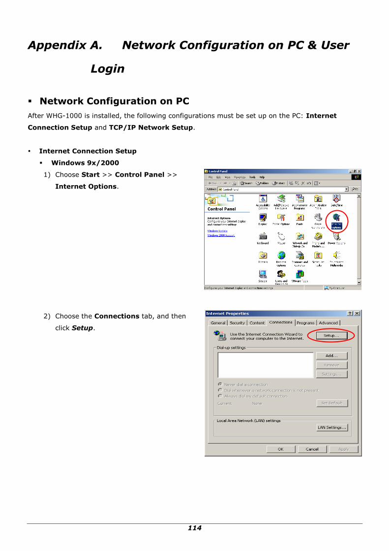
114
Appendix A. Network Configuration on PC & User
Login
Network Configuration on PC
After WHG-1000 is installed, the following configurations must be set up on the PC: Internet
Connection Setup and TCP/IP Network Setup.
Internet Connection Setup
Windows 9x/2000
1) Choose Start >> Control Panel >>
Internet Options.
2) Choose the Connections tab, and then
click Setup.

115
3) Choose “I want to set up my Internet
connection manually, or I want to
connect through a local Area network
(LAN)”, and then click Next.
4) Choose “I connect through a local area
network (LAN)” and then click Next.
5) DO NOT choose any option in the
following LAN window for Internet
configuration, and just click Next.
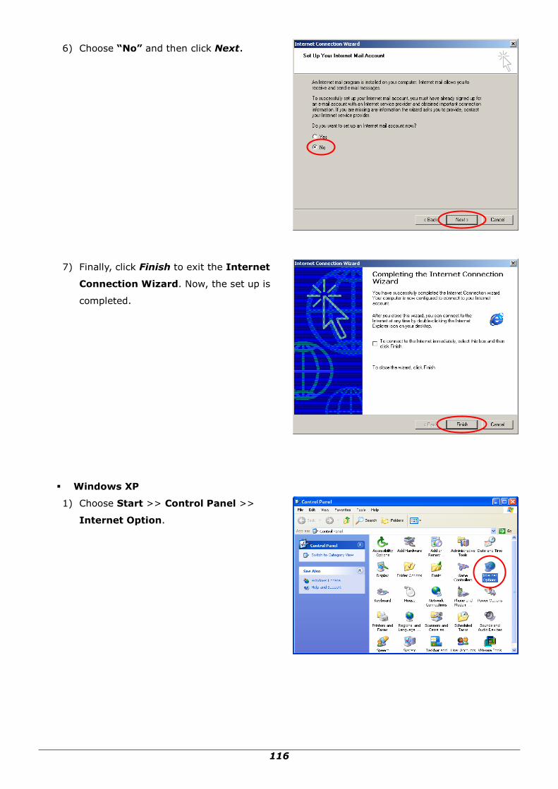
116
6) Choose “No” and then click Next.
7) Finally, click Finish to exit the Internet
Connection Wizard. Now, the set up is
completed.
Windows XP
1) Choose Start >> Control Panel >>
Internet Option.

117
2) Choose the Connections tab, and then
click Setup.
3) When the Welcome to the New
Connection Wizard window appears,
click Next.
4) Choose “Connect to the Internet” and
then click Next.

118
5) Choose “Set up my connection
manually” and then click Next.
6) Choose “Connect using a broadband
connection that is always on” and then
click Next.
7) Finally, click Finish to exit the
Connection Wizard. Now, the setup is
completed.
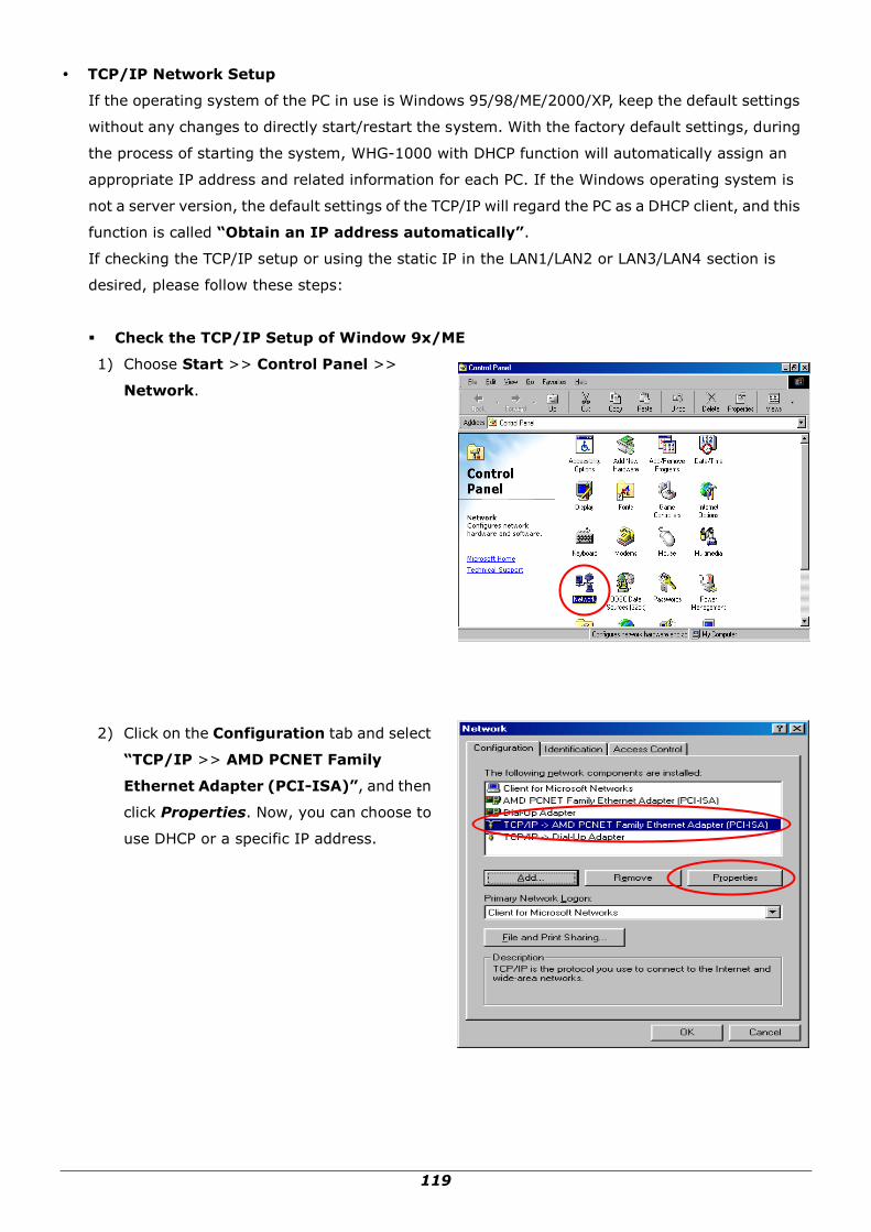
119
TCP/IP Network Setup
If the operating system of the PC in use is Windows 95/98/ME/2000/XP, keep the default settings
without any changes to directly start/restart the system. With the factory default settings, during
the process of starting the system, WHG-1000 with DHCP function will automatically assign an
appropriate IP address and related information for each PC. If the Windows operating system is
not a server version, the default settings of the TCP/IP will regard the PC as a DHCP client, and this
function is called “Obtain an IP address automatically”.
If checking the TCP/IP setup or using the static IP in the LAN1/LAN2 or LAN3/LAN4 section is
desired, please follow these steps:
Check the TCP/IP Setup of Window 9x/ME
1) Choose Start >> Control Panel >>
Network.
2) Click on the Configuration tab and select
“TCP/IP >> AMD PCNET Family
Ethernet Adapter (PCI-ISA)”, and then
click Properties. Now, you can choose to
use DHCP or a specific IP address.

120
3) Using DHCP: If you want to use DHCP,
click on the IP Address tab and choose
“Obtain an IP address automatically”,
and then click OK. This is also the default
setting of Windows. Then, reboot the PC to
make sure an IP address is obtained from
WHG-1000.
4) Using Specific IP Address: If you want to use a specific IP address, acquire the following
information from the network administrator: the IP Address, Subnet Mask and DNS Server
address provided by your ISP and the Gateway address of WHG-1000.
Caution:
If your PC has been set up completely, please inform the network administrator before proceeding to
the following steps.
4.1) Click on the IP Address tab and choose
“Specify an IP address”. Enter the IP
Address, Subnet Mask and then click
OK.
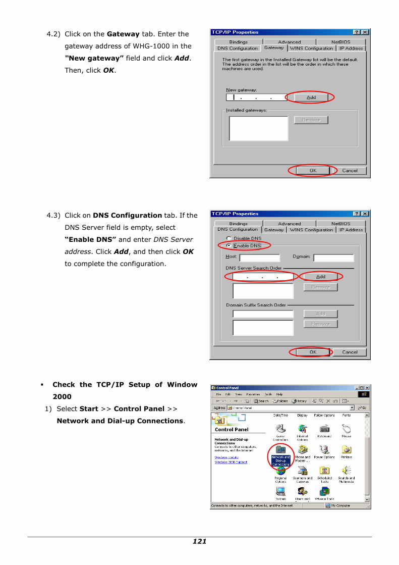
121
4.2) Click on the Gateway tab. Enter the
gateway address of WHG-1000 in the
“New gateway” field and click Add.
Then, click OK.
4.3) Click on DNS Configuration tab. If the
DNS Server field is empty, select
“Enable DNS” and enter DNS Server
address. Click Add, and then click OK
to complete the configuration.
Check the TCP/IP Setup of Window
2000
1) Select Start >> Control Panel >>
Network and Dial-up Connections.

122
2) Right click on the Local Area Connection
icon and select “Properties”.
3) Select “Internet Protocol (TCP/IP)”
and then click Properties. Now, you can
choose to use DHCP or a specific IP
address.
4) Using DHCP: If you want to use DHCP,
choose “Obtain an IP address
automatically”, and then click OK. This
is also the default setting of Windows.
Then, reboot the PC to make sure an IP
address is obtained from WHG-1000.

123
5) Using Specific IP Address: If you want to use a specific IP address, acquire the following
information from the network administrator: the IP Address, Subnet Mask and DNS Server
address provided by your ISP and the Gateway address of WHG-1000.
Caution:
If your PC has been set up completely, please inform the network administrator before proceeding to
the following steps.
5.1) Choose “Use the following IP
address” and enter the IP address,
Subnet mask. If the DNS Server field is
empty, select “Using the following
DNS server addresses” and enter the
DNS Server address. Then, click OK.
5.2) Click Advanced to enter the Advanced
TCP/IP Settings window.
5.3) Click on the IP Settings tab and click
Add below the “Default gateways”
column and the TCP/IP Gateway
Address window will appear.
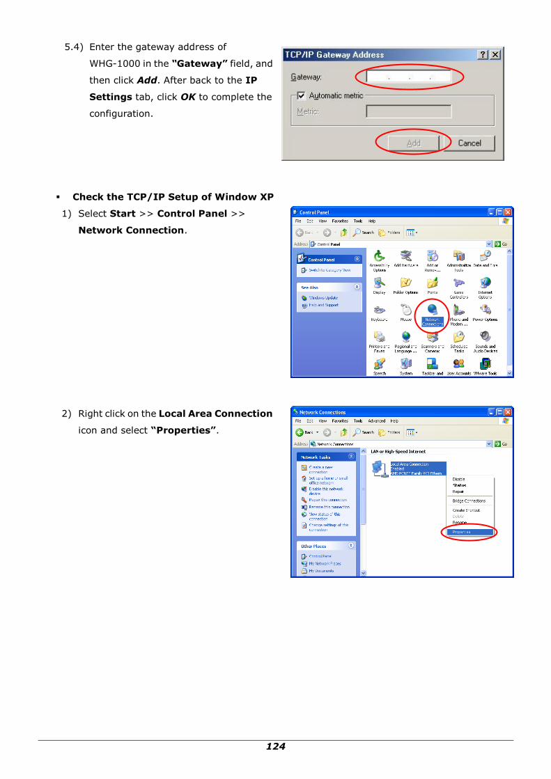
124
5.4) Enter the gateway address of
WHG-1000 in the “Gateway” field, and
then click Add. After back to the IP
Settings tab, click OK to complete the
configuration.
Check the TCP/IP Setup of Window XP
1) Select Start >> Control Panel >>
Network Connection.
2) Right click on the Local Area Connection
icon and select “Properties”.

125
3) Click on the General tab and choose
“Internet Protocol (TCP/IP)”, and
then click Properties. Now, you can
choose to use DHCP or a specific IP
address.
4) Using DHCP: If you want to use DHCP,
choose “Obtain an IP address
automatically” and click OK. This is also
the default setting of Windows. Then,
reboot the PC to make sure an IP address
is obtained from WHG-1000.
5) Using Specific IP Address: If you want
to use a specific IP address, acquire the
following information from the network
administrator: the IP Address, Subnet
Mask and DNS Server address provided by
your ISP and the Gateway address of WHG-1000.
Caution:
If your PC has been set up completely, please inform the network administrator before proceeding to
the following steps.

126
5.1) Choose “Use the following IP
address” and enter the IP address,
Subnet mask. If the DNS Server field is
empty, select “Using the following
DNS server addresses” and enter the
DNS Server address. Then, click OK.
5.2) Click Advanced to enter the Advanced
TCP/IP Settings window.
5.3) Click on the IP Settings tab and click
Add below the “Default gateways”
column and the TCP/IP Gateway
Address window will appear.
5.4) Enter the gateway address of WHG-1000
in the “Gateway” field, and then click
Add. After back to the IP Settings tab,
click OK to finish the configuration.

127
Appendix B. Policy Priority
Global Policy, Authentication Policy and User Policy
WHG-1000 supports multiple Policies, including one Global Policy and 5 individual Policy can be
assign to different Authentication Server. Global Policy is the system‟s universal policy and
applied to all clients, while other individual Policy can be selected and defined to be applied to any
Authentication Server. For some authentication, such as Local and RADIUS, user can be assigned to
different Policy individually. So one user may be applied different policy at the same time. Which policy
is actually applied to this user?
The Policy Priority are enforced as follows:
User Policy >> Authentication Policy >> Global Policy
Now, let us discus different user policy type:
For Local and RADIUS, the users can be assigned to different Policy individually. For example, a
Local user, user01, is assigned to Policy1 and the Local Authentication is assigned to Policy2.
Then user01 login to Public Zone will get Policy1. This is a common case for users that can assign
Policy individually.
For Local and RADIUS, if these users are not assigned any User Policy individually, they will be the
same as other users within the same authentication server. For example, a Local user, user01,
the Local Authentication is assigned to Policy3. Then user01 login to Public Zone will get Policy3.
This is another common case for users that is assigned Policy by the authentication server.
If User is not assigned a Policy individually and the authentication server is also not assigned a
Policy, then the users will be applied the Global Policy. For example, a Local user, user01, is
assigned to None Policy and the Local Authentication is also assigned to None Policy in User list.
Then user01 logging to Public Zone will be applied with the Global Policy.
As a conclusion, the Global Policy has the lowest policy priority; on the other hand, the User Policy has
the highest one.

128
Appendix C. WDS Management
The Public Zone of WHG-1000 supports up to 2 WDS links. WDS (Wireless Distribution System) is a
function used to connect APs (Access Points) wirelessly to extend wireless coverage. The WDS
management function of the system can help administrators to setup two WDS links.
Configure WDS, go to: System >> Zone Configuration, click Configure in Public zone.
WDS (Wireless Distribution System) is a function used to connect APs (Access Points) wirelessly. The
WDS management function of the system can help administrators to setup two WDS links.
WDS Status: Select Enable to active this WDS link.
MAC Address of Remote AP: Enter the MAC of the remote AP that create WDS link with
WHG-1000.
Security Type:
WEP: WEP Key Length may be 64 bits, 128 bits or 152 bits; and WEP Key Format can be
ASCII or HEX. Lastly, enter the WEP Key.
WPA-PSK: Select the preferred ciphering method, TKIP or AES and enter the PSK /
Pass-phrase.

129
Appendix D. RADIUS Accounting
This section will briefly introduce the basic configuration of RADIUS server to work with VSA for
the purpose to control the maximum client volume usage (upload; download or upload +
download traffic).
This VSA will be sent from RADIUS server to gateway along with an Access-Accept packet. In
other words, when the external RADIUS server accepts the request, it will reply not only an
Access-Accept but also a maximum value in bytes each user is allowed to transfer. This value
can be the maximum upload traffic, the maximum download traffic, or the sum of the download
and upload traffics in bytes per user. Gateway will check this value every minute; if the user
traffics reach this value, gateway will stop the session of this user and send a “Stop” to RADIUS
server.
1. Description
VSA is designed to allow vendors to support their own extended Attributes not covered in
common attributes. It MUST not affect the operation of the RADIUS protocol.
The Attribute Type of VSA is “26” and the “Vendor ID” should be determined before proceeding
to RADIUS configuration; in this example; the Vendor ID is “21920”. “Attribute Number” and
“Attribute Value” can then be designed to provide additional control over RADIUS.
Attribute Name Attribute
Number
Attribute Value
WHG-1000-Byte-Amount 10 To be defined by administrator for
different user group
WHG-1000-MaxByteIn 11 To be defined by administrator for
different user group
WHG-1000-MaxByteOut 12 To be defined by administrator for
different user group
WHG-1000-Byte-Amount-4GB 20 To be defined by administrator for
different user group
WHG-1000-MaxByteIn-4GB 21 To be defined by administrator for
different user group
WHG-1000-MaxByteOut-4GB 22 To be defined by administrator for
different user group
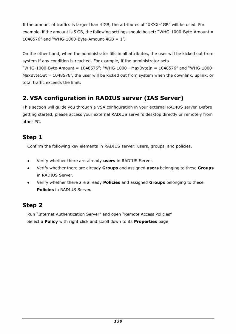
130
If the amount of traffics is larger than 4 GB, the attributes of “XXXX-4GB” will be used. For
example, if the amount is 5 GB, the following settings should be set: “WHG-1000-Byte-Amount =
1048576” and “WHG-1000-Byte-Amount-4GB = 1”.
On the other hand, when the administrator fills in all attributes, the user will be kicked out from
system if any condition is reached. For example, if the administrator sets
“WHG-1000-Byte-Amount = 1048576”; “WHG-1000 - MaxByteIn = 1048576” and “WHG-1000-
MaxByteOut = 1048576”, the user will be kicked out from system when the downlink, uplink, or
total traffic exceeds the limit.
2. VSA configuration in RADIUS server (IAS Server)
This section will guide you through a VSA configuration in your external RADIUS server. Before
getting started, please access your external RADIUS server‟s desktop directly or remotely from
other PC.
Step 1
Confirm the following key elements in RADIUS server: users, groups, and policies.
Verify whether there are already users in RADIUS Server.
Verify whether there are already Groups and assigned users belonging to these Groups
in RADIUS Server.
Verify whether there are already Policies and assigned Groups belonging to these
Policies in RADIUS Server.
Step 2
Run “Internet Authentication Server” and open “Remote Access Policies”
Select a Policy with right click and scroll down to its Properties page

131
Step 3
Click Edit Profile and select the Advanced Tag.
Click Add to add a new Vendor-specific attribute.

132
Step 4
Add a new attribute under Vendor-specific
Set “Vendor Code = 21920”.
Check Yes to conform to the RADIUS RFC.
Click Configure Attribute to proceed.
Set “Vendor-assigned attribute number = 10”
Select “Attribute format = Hexadecimal”
Set “Attribute Value = 1000000”
Step 5
Confirm whether the Vendor-specific Attribute has been added successfully

133
Step 6
Follow the same steps to create other Vendor-specific Attribute if needed.
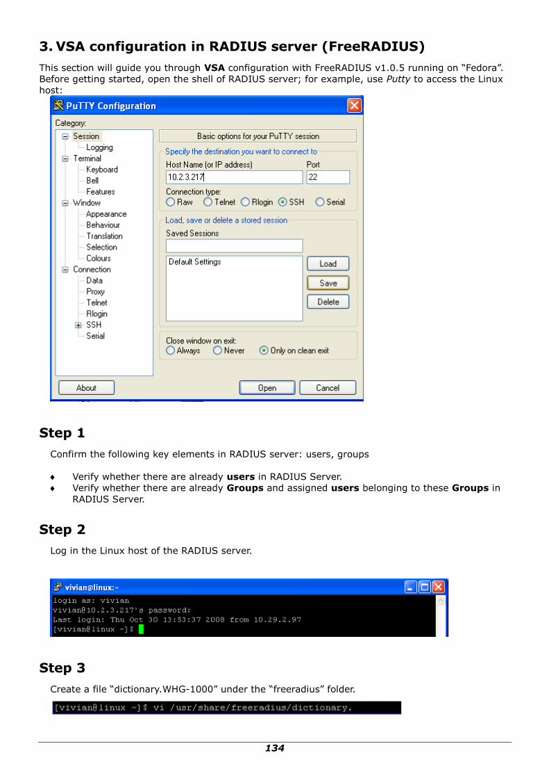
134
3. VSA configuration in RADIUS server (FreeRADIUS)
This section will guide you through VSA configuration with FreeRADIUS v1.0.5 running on “Fedora”.
Before getting started, open the shell of RADIUS server; for example, use Putty to access the Linux
host:
Step 1
Confirm the following key elements in RADIUS server: users, groups
Verify whether there are already users in RADIUS Server.
Verify whether there are already Groups and assigned users belonging to these Groups in
RADIUS Server.
Step 2
Log in the Linux host of the RADIUS server.
Step 3
Create a file “dictionary.WHG-1000” under the “freeradius” folder.

135
Step 4
Edit and save the contents of the file “dictionary.WHG-1000” as follows:
Administrator can also add other attributes as the table stated in Section 2 with the same format.
Step 5
Edit the file “dictionary” under the folder “freeradius”.

136
Step 6
To include “dictionary.WHG-1000” in the dictionary of RADIUS server, insert it in an incremental
position as follows.
Step 7
Open the “radius” database.
Step 8
Insert VSA into RADIUS response. In this example, the maximum download and upload traffics in
bytes for group03 users is 1MBytes.

137
Step 9
Restart RADIUS daemon to get your settings activated.
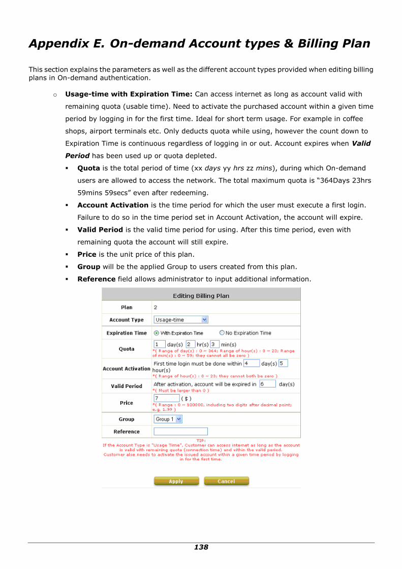
138
Appendix E. On-demand Account types & Billing Plan
This section explains the parameters as well as the different account types provided when editing billing
plans in On-demand authentication.
o Usage-time with Expiration Time: Can access internet as long as account valid with
remaining quota (usable time). Need to activate the purchased account within a given time
period by logging in for the first time. Ideal for short term usage. For example in coffee
shops, airport terminals etc. Only deducts quota while using, however the count down to
Expiration Time is continuous regardless of logging in or out. Account expires when Valid
Period has been used up or quota depleted.
Quota is the total period of time (xx days yy hrs zz mins), during which On-demand
users are allowed to access the network. The total maximum quota is “364Days 23hrs
59mins 59secs” even after redeeming.
Account Activation is the time period for which the user must execute a first login.
Failure to do so in the time period set in Account Activation, the account will expire.
Valid Period is the valid time period for using. After this time period, even with
remaining quota the account will still expire.
Price is the unit price of this plan.
Group will be the applied Group to users created from this plan.
Reference field allows administrator to input additional information.

139
o Usage-time with No Expiration Time: Can access internet as long as account has
remaining quota (usable time). Need to activate the purchased account within a given time
period by logging in for the first time. Ideal for short term usage. For example in coffee
shops, airport terminals etc. Only deducts quota while using. Account expires only when
quota depleted.
Quota is the total period of time (xx days yy hrs zz mins), during which On-demand
users are allowed to access the network. The total maximum quota is “364Days 23hrs
59mins 59secs” even after redeem.
Account Activation is the time period for which the user must execute a first login.
Failure to do so in the time period set in Account Activation, the account will expire.
Price is the unit price of this plan.
Group will be the applied Group to users created from this plan.
Reference field allows administrator to input additional information.

140

141
Hotel Cut-off-time: Hotel Cut-off-time is the clock time (normally check-out time) at
which the on-demand account is cut off (made expired) by the system on the following
day or many days later. On the account creation UI of this plan, operator can enter a Unit
value which is the number of days to Cut-off-time according to customer stay time. For
example: Unit = 2 days, Cut-off Time = 13:00 then account will expire on 13:00 two
days later. Grace Period is an additional, short period of time after the account is cut off
that allows user to continue to use the on-demand account to access the Internet
without paying additional fee. Unit Price is a daily price of this billing plan. Mainly used
in hostel venues to provide internet service according to guests‟ stay time. Group will be
the applied Group to users created from this plan. Reference field allows administrator
to input additional information.

142
o Volume: Can access internet as long as account valid with remaining quota (traffic volume).
Account expires when Valid Period has been used up or quota depleted. Ideal for small
quantity applications such as sending/receiving mail, transferring a file etc. Count down of
Valid Period is continuous regardless of logging in or out.
Quota is the total Mbytes (1~2000), during which On-demand users are allowed to
access the network.
Account Activation is the time period for which the user must execute a first login.
Failure to do so in the time period set in Account Activation, the account will expire.
Valid Period is the valid time period for using. After this time period, even with
remaining quota the account will still expire.
Price is the unit price of this plan.
Group will be the applied Group to users created from this plan.
Reference field allows administrator to input additional information.
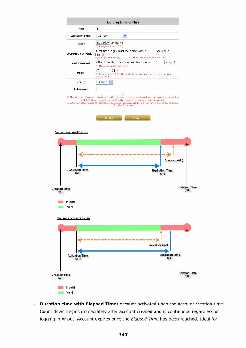
143
o Duration-time with Elapsed Time: Account activated upon the account creation time.
Count down begins immediately after account created and is continuous regardless of
logging in or out. Account expires once the Elapsed Time has been reached. Ideal for

144
providing internet service immediately after account creation throughout a specific period of
time.
Begin Time is the time that the account will be activated for use. It is set to account
creation time.
Elapsed Time is the time interval for which the account is valid for internet access (xx
hrs yy mins).
Price is the unit price of this plan.
Group will be the applied Group to users created from this plan.
Reference field allows administrator to input additional information.
o Duration-time with Cut-off Time: Cut-off Time is the clock time at which the
on-demand account is cut off (made expired) by the system on that day. For example a
shopping mall closing hour is 23:00, operators selling on-demand tickets can create use this

145
plan to create ticket set to be Cut-off on 23:00. If an account of this kind is created after the
Cut-off Time, the account will automatically expire.
Begin Time is the time that the account will be activated for use. It is set to account
creation time.
Cut-off Time is the clock time when the account will expire.
Price is the unit price of this plan.
Group will be the applied Group to users created from this plan.
Reference field allows administrator to input additional information.
o Duration-time with Begin-and End Time: Define explicitly the Begin Time and End Time
of the account. Count down begins immediately after account activation and expires when
the End Time has been reached. Ideal for providing internet service throughout a specific

146
period of time. For example during exhibition events or large conventions such as Computex
where each registered participant will get an internet account valid from 8:00 AM Jun 1 to
5:00 PM Jun 5 created in batch like coupons.
Begin Time is the time that the account will be activated for use, defined explicitly by
the operator.
End Time is the time that the account will become expired and not able to use any more,
defined explicitly by the operator.
Price is the unit price of this plan.
Group will be the applied Group to users created from this plan.
Reference field allows administrator to input additional information.
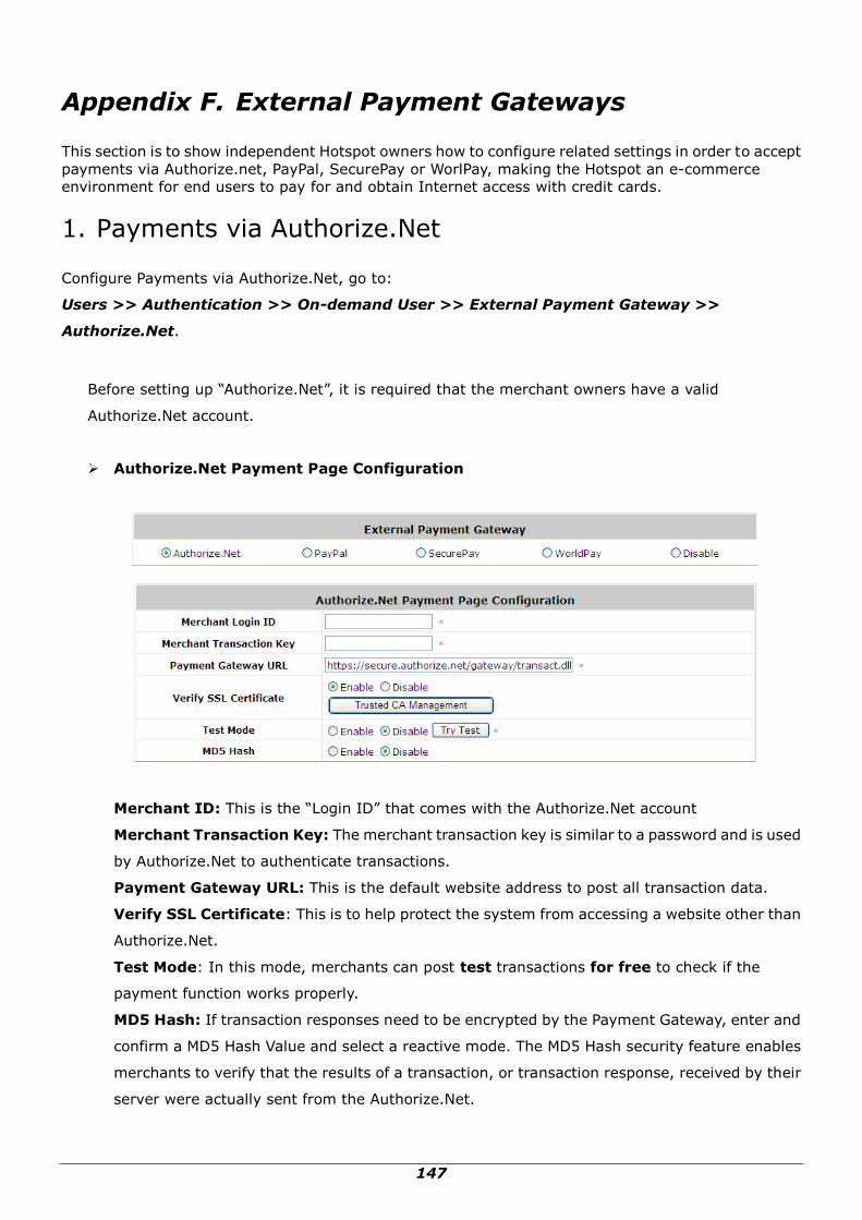
147
Appendix F. External Payment Gateways
This section is to show independent Hotspot owners how to configure related settings in order to accept
payments via Authorize.net, PayPal, SecurePay or WorlPay, making the Hotspot an e-commerce
environment for end users to pay for and obtain Internet access with credit cards.
1. Payments via Authorize.Net
Configure Payments via Authorize.Net, go to:
Users >> Authentication >> On-demand User >> External Payment Gateway >>
Authorize.Net.
Before setting up “Authorize.Net”, it is required that the merchant owners have a valid
Authorize.Net account.
Authorize.Net Payment Page Configuration
Merchant ID: This is the “Login ID” that comes with the Authorize.Net account
Merchant Transaction Key: The merchant transaction key is similar to a password and is used
by Authorize.Net to authenticate transactions.
Payment Gateway URL: This is the default website address to post all transaction data.
Verify SSL Certificate: This is to help protect the system from accessing a website other than
Authorize.Net.
Test Mode: In this mode, merchants can post test transactions for free to check if the
payment function works properly.
MD5 Hash: If transaction responses need to be encrypted by the Payment Gateway, enter and
confirm a MD5 Hash Value and select a reactive mode. The MD5 Hash security feature enables
merchants to verify that the results of a transaction, or transaction response, received by their
server were actually sent from the Authorize.Net.

148
Service Disclaimer Content/ Choose Billing Plan for Authorize.Net Payment
Page/Client’s Purchasing Record
Service Disclaimer Content
View service agreements and fees for the standard payment gateway services here
as well as adding new or editing services disclaimer.
Choose Billing Plan for Authorize.Net Payment Page
These 10 plans are the plans configured in Billing Plans page, and all previously
enabled plans can be further enabled or disabled here, as needed.
Client’s Purchasing Record
o Starting Invoice Number: An invoice number may be provided as additional
information with a transaction. The number will be incremented automatically for
each following transaction. Click the “Change the Number” checkbox to change it.
o Description (Item Name): This is the item information to describe the product
(for example, Internet Access).
o Email Header: Enter the information that should appear in the header of the
invoice.
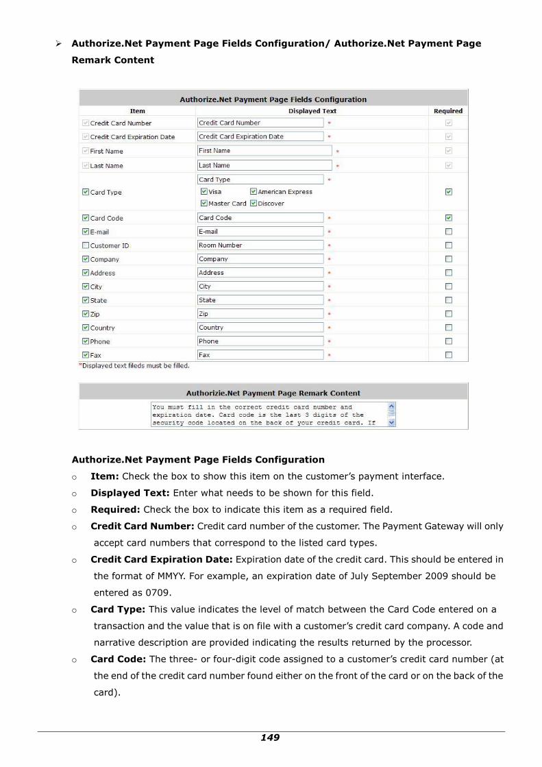
149
Authorize.Net Payment Page Fields Configuration/ Authorize.Net Payment Page
Remark Content
Authorize.Net Payment Page Fields Configuration
o Item: Check the box to show this item on the customer‟s payment interface.
o Displayed Text: Enter what needs to be shown for this field.
o Required: Check the box to indicate this item as a required field.
o Credit Card Number: Credit card number of the customer. The Payment Gateway will only
accept card numbers that correspond to the listed card types.
o Credit Card Expiration Date: Expiration date of the credit card. This should be entered in
the format of MMYY. For example, an expiration date of July September 2009 should be
entered as 0709.
o Card Type: This value indicates the level of match between the Card Code entered on a
transaction and the value that is on file with a customer‟s credit card company. A code and
narrative description are provided indicating the results returned by the processor.
o Card Code: The three- or four-digit code assigned to a customer‟s credit card number (at
the end of the credit card number found either on the front of the card or on the back of the
card).

150
o E-mail: An email address may be provided along with the billing information of a
transaction. This is the
customer‟s email address and should contain an @ symbol.
o Customer ID: This is an internal identifier for a customer that may be associated with the
billing information of a transaction. This field may contain any format of information.
o First Name: The first name of a customer associated with the billing or shipping address of
a transaction. In the case when John Doe places an order, enter John in the First Name field
indicating this customer‟s name.
o Last Name: The last name of a customer associated with the billing or shipping address of
a transaction. In the case when John Doe places an order, enter Doe in the Last Name field
indicating this customer‟s name.
o Company: The name of the company associated with the billing or shipping information
entered on a given transaction.
o Address: The address entered either in the billing or shipping information of a given
transaction.
o City: The city is associated with either the billing address or shipping address of a
transaction.
o State: A state is associated with both the billing and shipping address of a transaction. This
may be entered as either a two-character abbreviation or the full text name of the state.
o Zip: The ZIP code represents the five or nine digit postal code associated with the billing or
shipping address of a transaction. This may be entered as five digits, nine digits, or five
digits and four digits.
o Country: The country is associated with both the billing and shipping address of a
transaction. This may be entered as either an abbreviation or full name.
o Phone: A phone number is associated with both a billing and shipping address of a
transaction. Phone number information may be entered as all number or it may include
parentheses or dashes to separate the area code and number.
o Fax: A fax number may be associated with the billing information of a transaction. This
number may be entered as all number or contain parentheses and dashes to separate the
area code and number.
Authorizie.Net Payment Page Remark Content
Enter additional details for the transaction such as Tax, Freight and Duty Amounts, Tax Exempt
status, and a Purchase Order Number, if applicable.

151
2. Payments via PayPal
Configure Payments via PayPal, go to:
User >> Authentication >> On-demand User >> External Payment Gateway >> PayPal.
Before setting up “PayPal”, it is required that the hotspot owners have a valid PayPal “Business
Account”.
After opening a PayPal Business Account, the hotspot owners should find the “Identity Token” of
this PayPal account to continue “PayPal Payment Page Configuration”.
External Payment Gateway / PayPal Payment Page Configuration
o Business Account: The “Login ID” (an email address) that is associated with the PayPal
Business Account.
o Payment Gateway URL: The default website address to post all transaction data.
o Identity Token: This is the key used by PayPal to validate all the transactions.
o Verify SSL Certificate: This is to help protect the system from accessing a website other
than PayPal
o Currency: The currency to be used for the payment transactions.

152
Service Disclaimer Content / Choose Billing Plan for PayPal Payment Page
o Service Disclaimer Content: View the service agreement and fees for the standard
payment gateway services as well as add or edit the service disclaimer content here.
o Choose Billing Plan for PayPal Payment Page: These 10 plans are the plans in Billing
Configuration, and the desired plan(s) can be enabled.
Client’s Purchasing Record / PayPal Payment Page Remark Content
Client’s Purchasing Record:
o Starting Invoice Number: An invoice number may be provided as additional information
against a transaction. This is a reference field that may contain any kind of information.
o Description: Enter the product/service description (e.g. wireless access service).
o Title for Message to Seller: Enter the information that will appear in the header of the
PayPal payment page.
PayPal Payment Page Remark Content: The message content will be displayed as a special
notice to end customers in the page of “Rate Plan”. For example, it can describe the cautions for
making a payment via PayPal.

153
3. Payments via SecurePay
Configure Payments via SecurePay, go to: Users >> Authentication >> On-demand User>>
External Payment Gateway >> SecurePay.
Before setting up “SecurePay”, it is required that the hotspot owners have a valid SecurePay
“Merchant Account” from its official website.

154
SecurePay Page Configuration
Merchant ID: The ID that is associated with the Merchant Account.
Merchant Password: This is the key used by Secure Pay to validate all the transactions.
Payment Gateway URL: The default website address to post all transaction data.
Verify SSL Certificate: This is to help protect the system from accessing a website other
than Secure Pay.
Currency: The currency to be used for the payment transactions.
Service Disclaimer Content
View the service agreement and fees for the standard payment gateway services as well as
add or edit the service disclaimer content here.
Choose Billing Plan for SecurePay Payment Page
These 10 plans are the plans in Billing Configuration, and the desired plan(s) can be
enabled.
SecurePay Payment Page Remark Content
The message content will be displayed as a special notice to end customers.
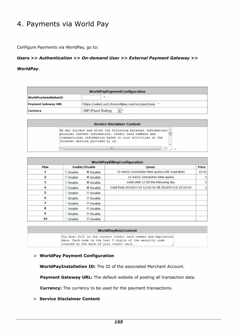
155
4. Payments via World Pay
Configure Payments via WorldPay, go to:
Users >> Authentication >> On-demand User >> External Payment Gateway >>
WorldPay.
WorldPay Payment Configuration
WorldPayInstallation ID: The ID of the associated Merchant Account.
Payment Gateway URL: The default website of posting all transaction data.
Currency: The currency to be used for the payment transactions.
Service Disclaimer Content

156
View the service agreement and fees for the standard payment gateway services as well as
add or edit the service disclaimer content here.
WorldPay Billing Configuration
These 10 plans are the plans in Billing Configuration, and the desired plan(s) can be
enabled.
WorldPay Note Content
The message content will be displayed as a special notice to end customers.
Before setting up “WorldPay”, it is required that the hotspot owners have a valid WorldPay “Merchant
Account” from its official website: RBS WorldPay: Merchant Services & Payment Processing, going to
rbsworldpay.com >> support center >> account login.
STEP①. Log in to the Merchant Interface.
Login url: www.rbsworldpay.com/support/index.php?page=login&c=WW
Select Business Gateway - Formerly WorldPay
Click Merchant Interface
Username: user2009
Password: user2009
STEP②. Select Installations from the left hand navigation
STEP③. Choose an installation and select the Integration Setup button for the specific environment.
Installation ID: 239xxx

157
STEP④. Check the Enable Payment Response checkbox.
STEP⑤. Enter the Payment Response URL.
URL : <wpdisplay item=MC_callback>
STEP⑥. Check the Enable the Shopper Response.

158
STEP⑦. Select the Save Changes button
STEP⑧. Input Installation ID and Payment Gateway URL in gateway UI.
Installation ID: 2009test
URL : https://select.wp3.rbsworldpay.com/wcc/purchase
Note: The WAN IP of gateway must be real IP.
P/N: V10020100618