combicom f5 - ontrium.com
TRANSCRIPT
COMBICOM F5INSTRUCTIONS FOR USE | PROFIBUS OPERATOR
Translation of the original manualDocument 20114545 EN 01

GB - 3
Table of Contents
1. General Information ........................................................................................................... 42. Order Informations ............................................................................................................ 43. F5-PROFIBUS-DP interface ............................................................................................... 44 Hardware Description........................................................................................................ 54.1 Diagnostic Interface ....................................................................................................................................... 54.2 PROFIBUS-DP interface ................................................................................................................................. 54.2.1 PROFIBUS-DPspecifications .......................................................................................................................... 6
5. Changeover from F4-PROFIBUS-DP to F5-PROFIBUS-DP interface connection ........ 66 Functions ............................................................................................................................ 86.1 PROFIBUS-DP services ................................................................................................................................. 86.2 Three funktion blocks .................................................................................................................................... 86.2.1 Processoutputdataprocessing ....................................................................................................................... 86.2.2 Processinputdataprocessing ......................................................................................................................... 86.2.3 Parameterizing channel ................................................................................................................................. 96.3 Process data and their mapping ................................................................................................................... 96.4 ConfigurationoftheFIforthedefaultprocessdataassignment ............................................................ 106.5 Cyclic communication mode ....................................................................................................................... 10
7 PROFIBUS-DP Basic Data ............................................................................................... 117.1 Parameterizing .............................................................................................................................................. 117.2 Configuration ................................................................................................................................................ 127.2.1 FlexiblePROFIBUSconfiguration .................................................................................................................. 137.3 PROFIBUS-DP diagnostic data ................................................................................................................... 147.4 User data of the KEB PROFIBUS-DP interface connection ...................................................................... 147.4.1 CodingoftheuserdatafromDPmastertoKEBDPinterfaceconnection ..................................................... 147.4.2 CodingofuserdatafromtheKEBDPinterfaceconnectiontothemaster ..................................................... 157.4.3 Notefortheuseofthedatalengthoftheparameters .................................................................................... 167.5 Realization of the parameterizing channel protocol at the master .......................................................... 177.5.1 Examplesforatelegramsequenceoftheparameterizingchannel ................................................................ 18
8. PROFIBUS-DP Operating Parameters ........................................................................... 208.1 Node address ................................................................................................................................................ 208.2 Transmission rate ......................................................................................................................................... 20
9. Application Parameters................................................................................................... 219.1 ConfigurationParameters .......................................................................................................................... 229.1.1 DRIVECOMprofileparametersintheindexrangeupto6000h ...................................................................... 31
10. Access to Operator Parameters ..................................................................................... 3510.1 Access via keyboard/display ....................................................................................................................... 3510.2 Access via diagnostic interface .................................................................................................................. 35
11. KEB PROFIBUS-DP Compact ......................................................................................... 4012. Annex ................................................................................................................................ 4112.1 Parameter overview ...................................................................................................................................... 4112.2 Error messages on the F5-operator display .............................................................................................. 4312.3 List of Literature ........................................................................................................................................... 4412.4 Table error messages of the parameterizing channel ............................................................................... 4412.5 UnitmasterfileforKEBF5PROFIBUS-DPoperator ................................................................................. 44
GB - 4
General Information
1. General InformationThe presented documentation as well as the herein mentioned hard- and software are developments of KEB Automation KG. Errors excepted. The KEB Automation KG have prepared the documentation, hardware and software to the best of their knowledge, however, no guarantee is given that the specifications will provide the efficiency aimed at by the user. The KEB Automation KG reserves the right to change the specifications without prior notification or further obligation. All rights reserved.
2. Order InformationsThis Instruction Manual: 20114545KEB F5-PROFIBUS-DP-Operator: 00F5060-3000
Utilities for the diagnostic interface:HSP5-cable between PC and adapter: 00F50C0-0010Adapter DSUB9 / Western: 00F50C0-0020
3. F5-PROFIBUS-DP interfaceKEB power transmission develop, produce and sell static frequency inverters worldwide in the industrial power range. The inverters of the type F5 can be equipped optionally with a KEB F5-PROFIBUS-DP interface. It con-cerns an intelligent interface, that controls the access over PROFIBUS-DP to the parameters of the frequency inverter.
The KEB F5-PROFIBUS-DP operator is integrated into the FI housing by plug-in and fits into all KEB F5 fre-quency inverters. Parallel to the fieldbus operation the operation over the integrated display/keyboard as well as another interface for diagnosis/parameterization (KEB COMBIVIS) is possible.
For programming the KEB F5 frequency inverter by PROFIBUS-DP the user requires in addition to this manual the instruction manual of the respective frequency inverter control.
GB - 5
Hardware Description
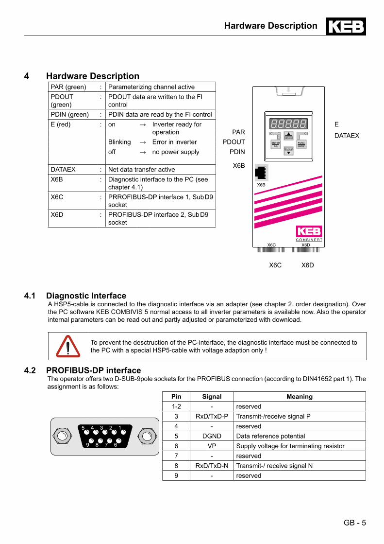
4 Hardware DescriptionPAR (green) : Parameterizing channel active
START
FUNC.
SPEED
ENTER
F/RSTOP
C O M B I V E R T
X6C X6D
X6B
X6C X6D
PDOUT (green)
: PDOUT data are written to the FI control
PDIN (green) : PDIN data are read by the FI controlE (red) : on → Inverter ready for
operation PARE
DATAEXBlinking → Error in inverter PDOUToff → no power supply PDIN
X6BDATAEX : Net data transfer activeX6B : Diagnostic interface to the PC (see
chapter 4.1)X6C : PRROFIBUS-DP interface 1, Sub D9
socketX6D : PROFIBUS-DP interface 2, Sub D9
socket
4.1 Diagnostic InterfaceA HSP5-cable is connected to the diagnostic interface via an adapter (see chapter 2. order designation). Over the PC software KEB COMBIVIS 5 normal access to all inverter parameters is available now. Also the operator internal parameters can be read out and partly adjusted or parameterized with download.
To prevent the desctruction of the PC-interface, the diagnostic interface must be connected to the PC with a special HSP5-cable with voltage adaption only !
4.2 PROFIBUS-DP interface The operator offers two D-SUB-9pole sockets for the PROFIBUS connection (according to DIN41652 part 1). The
assignment is as follows:
5 4 3 2 1
9 8 7 6
5 4 3 2 1
9 8 7 6
Pin Signal Meaning1-2 - reserved3 RxD/TxD-P Transmit-/receive signal P4 - reserved5 DGND Data reference potential6 VP Supply voltage for terminating resistor7 - reserved8 RxD/TxD-N Transmit-/ receive signal N9 - reserved
GB - 6
Hardware Description
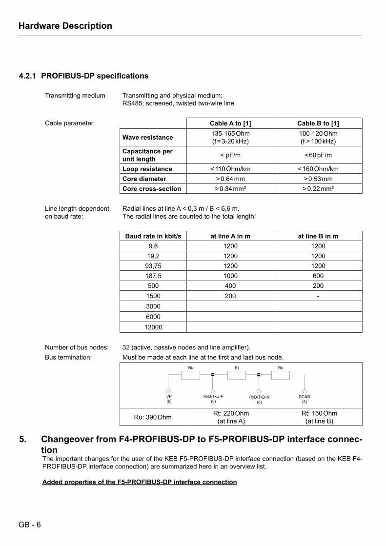
4.2.1 PROFIBUS-DPspecifications
Transmitting medium Transmitting and physical medium:RS485; screened, twisted two-wire line
Cable parameter Cable A to [1] Cable B to [1]
Wave resistance 135-165 Ohm(f = 3-20 kHz)
100-120 Ohm(f > 100 kHz)
Capacitance per unit length < 30 pF/m < 60 pF/m
Loop resistance < 110 Ohm/km < 160 Ohm/kmCore diameter > 0.64 mm > 0.53 mmCore cross-section > 0.34 mm² > 0.22 mm²
Line length dependent on baud rate:
Radial lines at line A < 0,3 m / B < 6,6 m.The radial lines are counted to the total length!
Baud rate in kbit/s at line A in m at line B in m9.6 1200 1200
19,2 1200 120093,75 1200 1200187,5 1000 600500 400 200
1500 200 -3000600012000
Number of bus nodes: 32 (active, passive nodes and line amplifier).Bus termination: Must be made at each line at the first and last bus node.
RuRtRu
VP(6)
RxD/TxD-P(3)
RxD/TxD-N(8)
DGND(5)
Ru: 390 Ohm Rt: 220 Ohm(at line A)
Rt: 150 Ohm(at line B)
5. Changeover from F4-PROFIBUS-DP to F5-PROFIBUS-DP interface connec-tion
The important changes for the user of the KEB F5-PROFIBUS-DP interface connection (based on the KEB F4-PROFIBUS-DP interface connection) are summarized here in an overview list.
Added properties of the F5-PROFIBUS-DP interface connection

GB - 7
Hardware Description
- Second PROFIBUS-DP connector to forwarding the PROFIBUS-DP bus or plug-on of a terminating resi-stor.
- Adaptability to the preset configuration of the master.- Direct set-addressing at inverter parameters via parameterizing channel subindex (see chapter 9).- Programming and diagnostics via keyboard and display of the PROFIBUS-DP operator.- Additional diagnostics and programming interface for KEB COMBIVIS (see chapter 10).
Changes
- Changed ident number (see unit main data).- Changed default process data assignment (see chapter 9.1.1).- Uniform data length setting possible (see chapter 7.4.3).
GB - 8
Functions
6 Functions
6.1 PROFIBUS-DP services The PROFIBUS-DP interface connection provides the following services or functions:
Data_Exchange Transfer of input and output dataRD_Inp Read inputs of a slaveRD_Outp Read outputs of a slaveSlave_Diag Read DP slave diagnostics informationSet_Prm Transmit parameter dataChk_Cfg Check configuration informationGet_Cfg Read out configuration informationGlobal_Control Control command
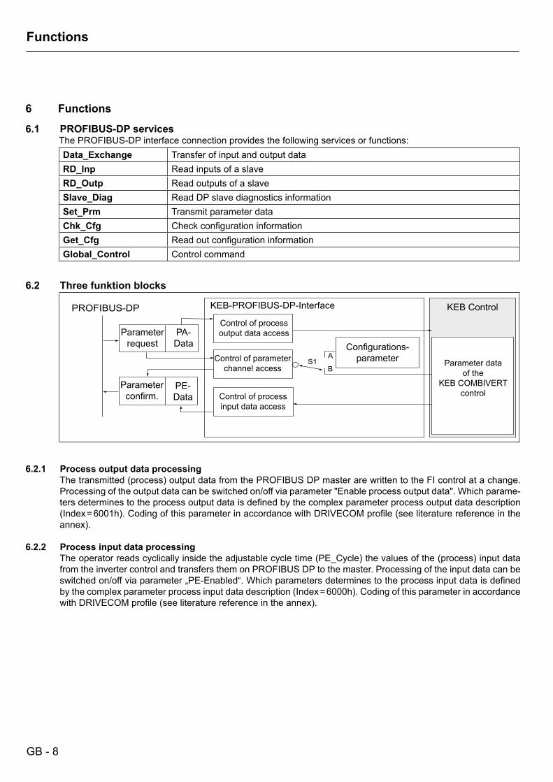
6.2 Three funktion blocks
PROFIBUS-DP
S1A
B
6.2.1 Process output data processingThe transmitted (process) output data from the PROFIBUS DP master are written to the FI control at a change. Processing of the output data can be switched on/off via parameter "Enable process output data". Which parame-ters determines to the process output data is defined by the complex parameter process output data description (Index = 6001h). Coding of this parameter in accordance with DRIVECOM profile (see literature reference in the annex).
6.2.2 Process input data processingThe operator reads cyclically inside the adjustable cycle time (PE_Cycle) the values of the (process) input data from the inverter control and transfers them on PROFIBUS DP to the master. Processing of the input data can be switched on/off via parameter „PE-Enabled“. Which parameters determines to the process input data is defined by the complex parameter process input data description (Index = 6000h). Coding of this parameter in accordance with DRIVECOM profile (see literature reference in the annex).
Parameterrequest
PA-Data
Parameterconfirm.
PE-Data
KEB-PROFIBUS-DP-Interface
Control of process output data access
Control of parameter channel access
Control of process input data access
Configurations-parameter Parameter data
of the KEB COMBIVERT
control
KEB Control
GB - 9
Functions
6.2.3 Parameterizing channelAny parameters of the FI control and the PROFIBUS DP operator can be read out or changed via the parameteri-zing channel. If available, the parameterizing channel determines the first 8 bytes of the cyclic telegrams between DP master and PROFIBUS-DP interface connection. The parameterizing channel is more flexible, since the parameter is directly addressed here. However the realization of the parameterizing channel on the cyclic data traffic is also somewhat more complex than the delivery of new process data.
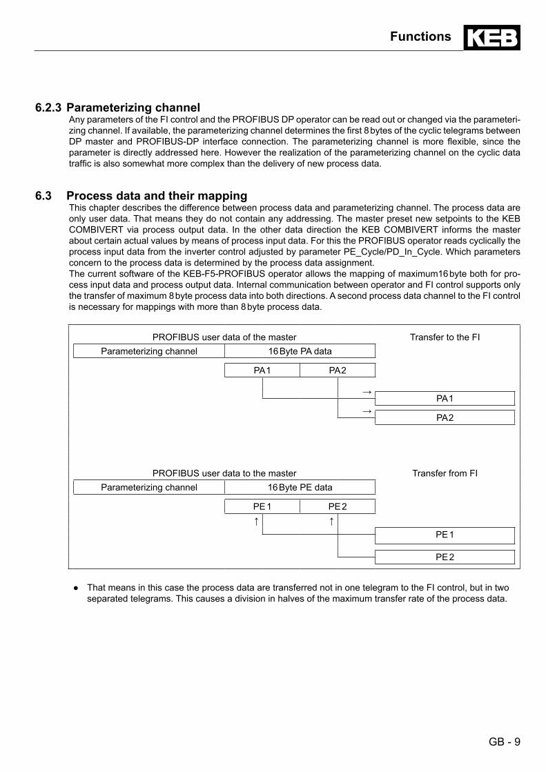
6.3 Process data and their mappingThis chapter describes the difference between process data and parameterizing channel. The process data are only user data. That means they do not contain any addressing. The master preset new setpoints to the KEB COMBIVERT via process output data. In the other data direction the KEB COMBIVERT informs the master about certain actual values by means of process input data. For this the PROFIBUS operator reads cyclically the process input data from the inverter control adjusted by parameter PE_Cycle/PD_In_Cycle. Which parameters concern to the process data is determined by the process data assignment. The current software of the KEB-F5-PROFIBUS operator allows the mapping of maximum16 byte both for pro-cess input data and process output data. Internal communication between operator and FI control supports only the transfer of maximum 8 byte process data into both directions. A second process data channel to the FI control is necessary for mappings with more than 8 byte process data.
PROFIBUS user data of the master Transfer to the FIParameterizing channel 16 Byte PA data
PA 1 PA 2
→PA 1
→PA 2
PROFIBUS user data to the master Transfer from FIParameterizing channel 16 Byte PE data
PE 1 PE 2↑ ↑
PE 1
PE 2
● That means in this case the process data are transferred not in one telegram to the FI control, but in two separated telegrams. This causes a division in halves of the maximum transfer rate of the process data.
GB - 10
Functions
6.4 ConfigurationoftheFIforthedefaultprocessdataassignment The default process data assignment of the PROFIBUS-DP operator links the parameters control word (Sy.50) and
setpoint speed (SY.52) to the process output data and parameters status word (Sy.51) and actual speed (Sy.53) to the process input data. Some parameters in the FI must be configured in order that the FI accept the preset values by the process output data as active setpoints. The following parameters are very important:
Parameter code Parameter-Name Default value Notice
OP.00 reference source 5OP.01 rotation source 8 other values are possibleDI.01 select signal source Bit0 = 1 only the value of bit0 is applicableDI.02 digital input setting Bit0 = 1 only the value of bit0 is applicable
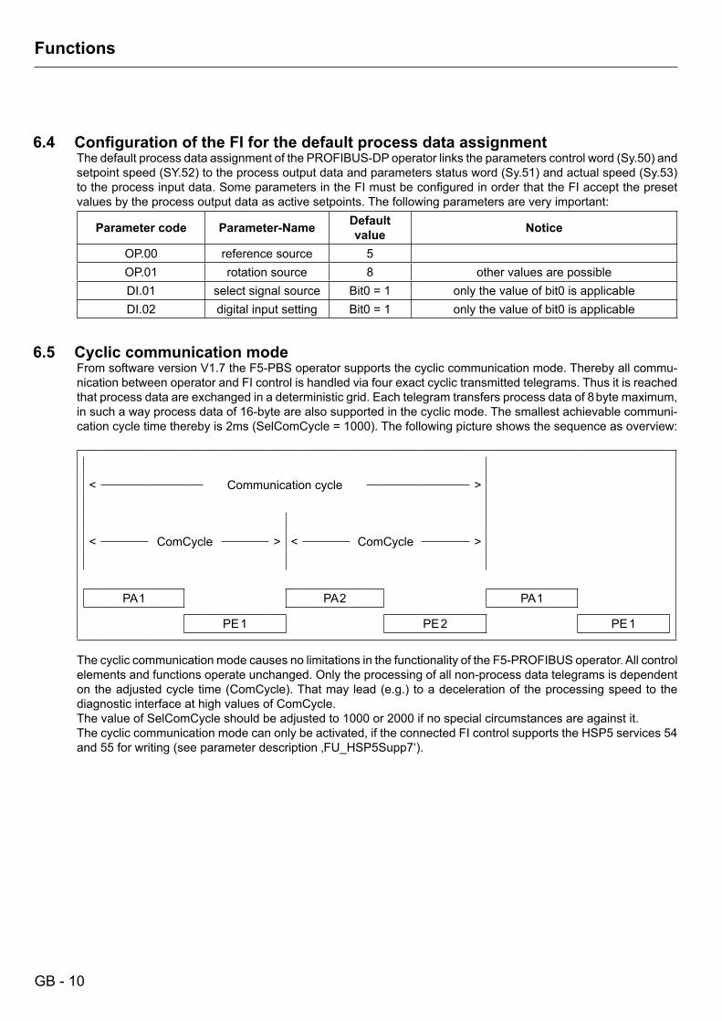
6.5 Cyclic communication mode From software version V1.7 the F5-PBS operator supports the cyclic communication mode. Thereby all commu-
nication between operator and FI control is handled via four exact cyclic transmitted telegrams. Thus it is reached that process data are exchanged in a deterministic grid. Each telegram transfers process data of 8 byte maximum, in such a way process data of 16-byte are also supported in the cyclic mode. The smallest achievable communi-cation cycle time thereby is 2ms (SelComCycle = 1000). The following picture shows the sequence as overview:
Communication cycle< >
ComCycle ComCycle< > < >
PA 1 PA 2 PA 1
PE 1 PE 2 PE 1
The cyclic communication mode causes no limitations in the functionality of the F5-PROFIBUS operator. All control
elements and functions operate unchanged. Only the processing of all non-process data telegrams is dependent on the adjusted cycle time (ComCycle). That may lead (e.g.) to a deceleration of the processing speed to the diagnostic interface at high values of ComCycle.
The value of SelComCycle should be adjusted to 1000 or 2000 if no special circumstances are against it. The cyclic communication mode can only be activated, if the connected FI control supports the HSP5 services 54
and 55 for writing (see parameter description ‚FU_HSP5Supp7‘).

GB - 11
Parameterizing
7 PROFIBUS-DP Basic Data The PROFIBUS-DP interface connection realizes a passive participant (slave). This means the PROFIBUS-DP
interface connection only transmits if it has been requested by the master.
The PROFIBUS-DP protocol defines different operating conditions, which must be pass through at first, before the actual user data can be exchanged. First the appropriate DP master must parameterize the slaves and afterwards it must configure them. The cyclic exchange of user data starts if these two functions are successfully executed.
Both parameterizing channel and process data only become active if the cyclic user data transfer is running.
7.1 Parameterizing The DP master must transmit 7 byte parameter data to the PROFIBUS-DP interface connection for a successful
parameterizing of it. According to the standard they have the following structure:
B7 : 00h (KEB) = Group Ident
B6 : EBh= Ident_Number
B5 : 05hB4 = Min_TsdrB3 = Watchdog_Factor_1B2 = Watchdog_Factor_2
B 1 = Station-StatusB7 = Lock_ReqB6 = Unlock_ReqB5 = Sync_ReqB4 = Freeze_ReqB3 = WD_On (1 = activated)B2 = reservedB 1 = reservedB0 = reserved
The response monitoring is activated or deactivated via Bit 3 of the station status (see above). The watchdog time is defined as follows:
TWD = Watchdog-Factor-1 * Watchdog-Factor-2 * 10 ms.
An activated response monitoring causes in error case (no receipt of a telegram within TWD) that the process output data are set to zero.
GB - 12
Configuration
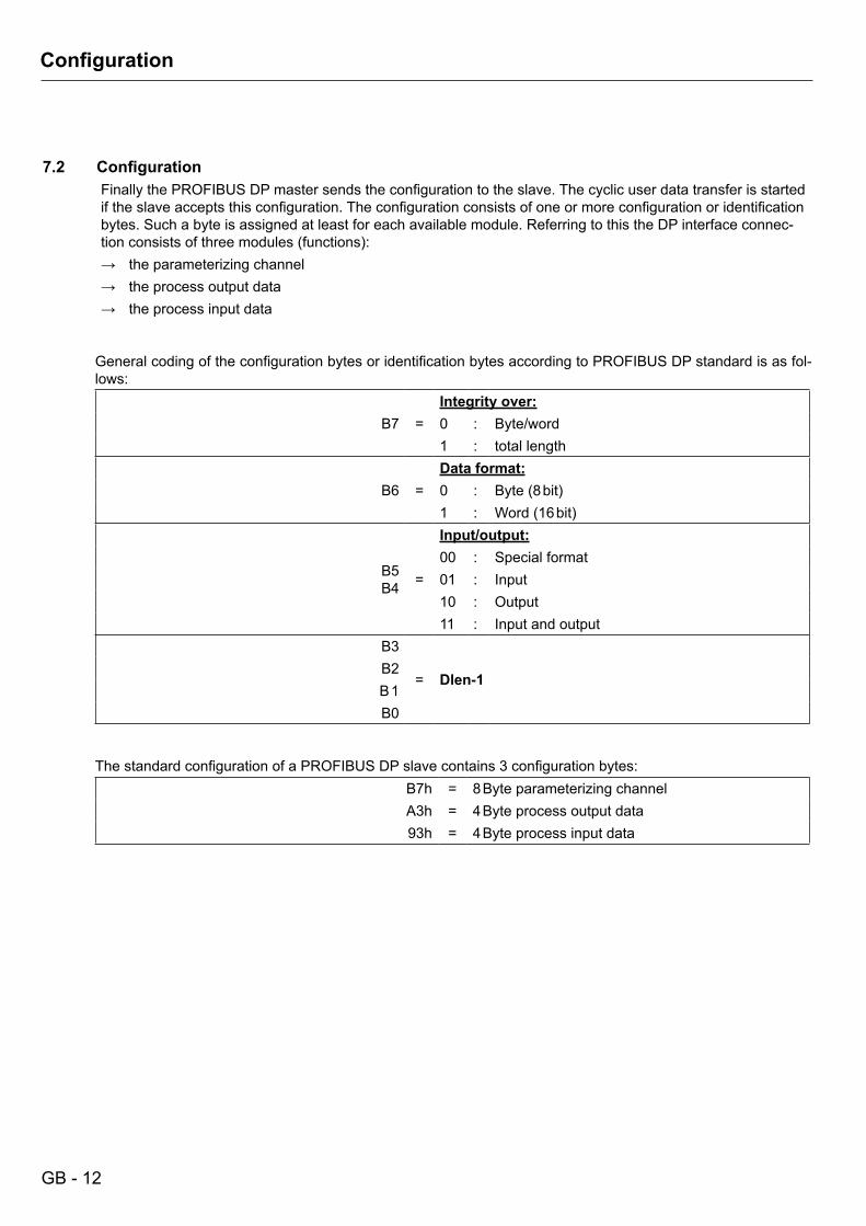
7.2 ConfigurationFinally the PROFIBUS DP master sends the configuration to the slave. The cyclic user data transfer is started if the slave accepts this configuration. The configuration consists of one or more configuration or identification bytes. Such a byte is assigned at least for each available module. Referring to this the DP interface connec-tion consists of three modules (functions):→ the parameterizing channel→ the process output data→ the process input data
General coding of the configuration bytes or identification bytes according to PROFIBUS DP standard is as fol-lows:
B7 =Integrity over:0 : Byte/word1 : total length
B6 =Data format:0 : Byte (8 bit)1 : Word (16 bit)
B5B4
Input/output:00 : Special format
= 01 : Input10 : Output11 : Input and output
B3
= Dlen-1B2B 1B0
The standard configuration of a PROFIBUS DP slave contains 3 configuration bytes:
B7h = 8 Byte parameterizing channelA3h = 4 Byte process output data93h = 4 Byte process input data

GB - 13
Configuration
7.2.1 FlexiblePROFIBUSconfiguration The preset PROFIBUS DP configuration by the master is handled very flexible in the current software. Thus it is
possible to divide the process data to several modules. One module can be defined maximally for each process data word (16-bit), so 17 modules (parameterizing channel (1)+process output data (8)+process input data (8)) can be configured maximally by the PROFIBUS master.
This is helpful e.g., if the process data for a slave on a master SPS are not in a consecutive memory range, but allocated in such way that the limited memory can be used optimally. This is described in the following with an example of default configuration (parameterizing channel + 4-byte PA data + 4-byte PE data):
a) Default configuration with 3 modules in byte structure:8-byte parameterizing channel 4-byte process output data 4-byte process input data
Cfg1 Cfg2 Cfg3B7h A3h 93h
b) Default configuration with division of the process output data to 2 modules in byte structure:
8-byte parameterizing channel 4-byte process output data 4-byte process input dataCfg1 Cfg2 Cfg3 Cfg4B7h A1h A1h 93h
c) Default configuration with division of the process output and input data to 2 modules in byte structure:
8-byte parameterizing channel 4-byte process output data 4-byte process input dataCfg1 Cfg2 Cfg3 Cfg4 Cfg5B7h A1h A1h 91h 91h
d) Default configuration with division of the process output and input data to 2 modules in word structure:
8-byte parameterizing channel 2-words process output data 2-words process input dataCfg1 Cfg2 Cfg3 Cfg4 Cfg5B7h E0h E0h D0h D0h
In spite of all flexibility the following regulations for the PROFIBUS DP configuration must be considered:
● If available, the parameterizing channel module must be activated with the first configuration byte and value "B7h".
● One configuration byte decsribes minimum one 16-bit word.

GB - 14
User Data
7.3 PROFIBUS-DP diagnostic data On request of the diagnostics data by a PROFIBUS-DP master the KEB PROFIBUS-DP responds with
6 byte diagnostics data (no user diagnostics), which are designed according to the draft standard DIN19245 part 3 as follows:
B6 : EBh= Ident number
B5 : 05hB4 = Node address of the master, which has parameterized the slaveB3 = Station status_3, bit-coded according to draft standardB2 = Station status_2, bit-coded according to draft standardB 1 = Station status_1, bit-coded according to draft standard
7.4 User data of the KEB PROFIBUS-DP interface connection Each user data telegram from DP master to KEB DP node has a user data length of 12 byte at default setting.
All user data telegrams from KEB DP node to DP master have the same user data length.
7.4.1 Coding of the user data from DP master to KEB DP interface connectionParameterizing channel demand Process output data
VW Sub-Index
Data/Error
PAD 1 PAD 2 PAD 3 PAD 4Index HW LWHB LB HB LB
SB 1 SB 2 SB 3 SB 4 SB 5 SB 6 SB 7 SB 8 SB 9 SB 10 SB 11 SB 12
VW B5 B4 Data length B 1 B0 Service request
Hand-shake
0 0 1 Byte 0 0 no serviceDlen-1 Service-Code
0 1 2 Byte 0 1 ReadWrite Read
1 0 3 Byte0 1 0 WriteB7 B6 B5 B4 B3 B2 B 1 B01 1 4 Byte 1 1 no service
1 Byte 2-byte value 4-byte value
HW LWLB HB LB HB LB HB LB
SB 5 SB 6 SB 7 SB 8 SB 5 SB 6 SB 7 SB 8 SB 5 SB 6 SB 7 SB 8
This means LB: Low-ByteHB: High-ByteLW: Low-WordHW: High-Word
GB - 15
User Data
Thefirst8 byte contain the parameterizing channel request. Request means, the DP master can inform the DP slave in this part of the telegram whether it wants to change (write) or scan (read) the value of a parameter.
The addressing of the parameter is done via 16-bit index and 8-bit subindex. The data length of the parameters, which can be responded via this parameter channel, is limited to 4 byte.
Limitations Some complex parameters cannot be read/written only with one parameterizing order via the KEB PROFIBUS-DP
interface connection. The user must access each part of this parameter/object separately (via subindex).
Thefirstbyteoftheparameterizingchannelrequestisamatterofspecialimportance(seechapter7.4.1).The parameterizing orders are carry out with this administration byte. This additional work is necessary, that the parameterizing orders can be treated detached from the cyclic exchange of the PROFIBUS-DP user data. The administration byte contains one handshake-bit. This bit must be inverted by the DP master each time if it wants to send a new parameterizing channel request.
Bit 4 and 5 of the administration byte indicates the data length. Bits b 0 and b 1 contain the service coding. If the DP master wants to inquire (read) the parameter value of a KEB DP node, bit b 0 must be 1 and bit b 1 = 0 .
Otherwise set b 0 = 0 and bit b 1 = 1, if the value of a parameter shall be changed (write).
Index and subindex must be set for addressing of the parameter. In case of a write request the data length and the data must be entered additionally as described above.
The second part of the user data telegram includes the (process) output data. These data are non-addressed, i.e. they do not contain a parameter address, but only data. Where these data are mapped was already described in the chapter of the function of the KEB PROFIBUS-DP interface connection.
Observe! Process output data are only transferred to the KEB COMBIVERT if these values have changed!
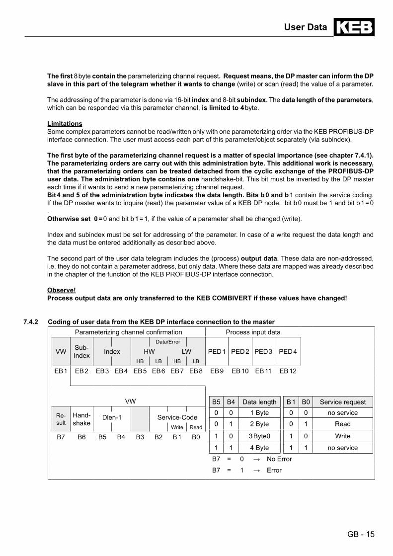
7.4.2 Coding of user data from the KEB DP interface connection to the masterParameterizing channel confirmation Process input data
VW Sub-Index
Data/Error
PED 1 PED 2 PED 3 PED 4Index HW LWHB LB HB LB
EB 1 EB 2 EB 3 EB 4 EB 5 EB 6 EB 7 EB 8 EB 9 EB 10 EB 11 EB 12
VW B5 B4 Data length B 1 B0 Service request
Re-sult
Hand-shake
0 0 1 Byte 0 0 no serviceDlen-1 Service-Code
0 1 2 Byte 0 1 ReadWrite Read
1 0 3 Byte0 1 0 WriteB7 B6 B5 B4 B3 B2 B 1 B01 1 4 Byte 1 1 no service
B7 = 0 → No Error
B7 = 1 → Error
GB - 16
User Data
The first 8 byte contain the parameterizing channel confirmation. That means, the DP master is informed whether his requested order could be executed error-free or not.
The first byte (administrative byte) has also a special meaning here. Bit b 6 (handshake) indicates whether the execution of the requested order is executed. The order is executed and the confirmation can be evaluated, if bit b 6 has the same value than the request. Bit b 7 indicates whether the requested order could be executed error free (b 7 = 0) or if an error occurs (b 7 = 1). The data/error field (byte EB 5 to EB 8) is to be interpreted as error de-scription in error case. The error divides in error class (EB 5), error code (EB 6) and additional code (EB 7,EB 8). The meaning of the individual error codes are specified in the annex. The data/error field contains the read out data, if no error occurs and the DP master has requested the reading of a parameter value.
Notice In case of a write request the written data from the request are also transferred to the confirmation if no error
occurs. In this case the DP master can read back the written data for compare.
Thesecondpartofthetelegramcontainsthe(process)input data. These data are first determined and then the data are entered in the PROFIBUS DP telegram. The input data are read cyclically with an adjustable cycle time. The mapping of the process input data can be taken from chapter 6.2.2 via the function of the KEB PROFIBUS-DP interface connection.
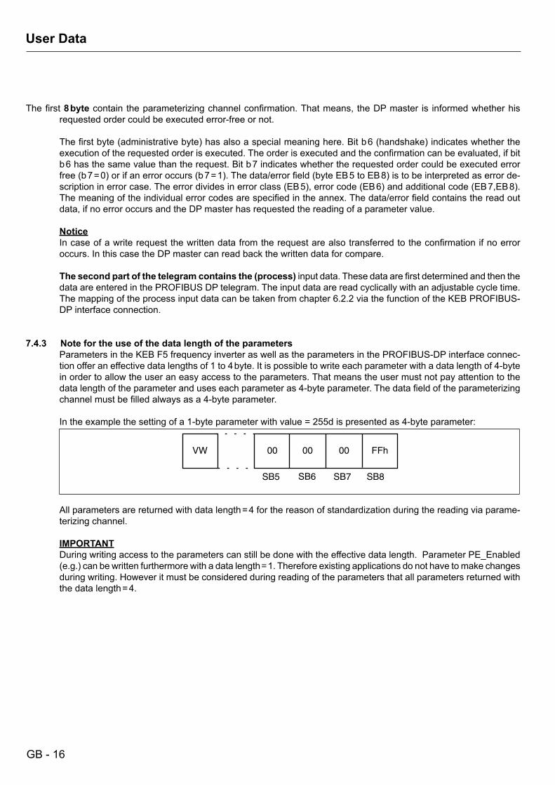
7.4.3 Note for the use of the data length of the parameters Parameters in the KEB F5 frequency inverter as well as the parameters in the PROFIBUS-DP interface connec-
tion offer an effective data lengths of 1 to 4 byte. It is possible to write each parameter with a data length of 4-byte in order to allow the user an easy access to the parameters. That means the user must not pay attention to the data length of the parameter and uses each parameter as 4-byte parameter. The data field of the parameterizing channel must be filled always as a 4-byte parameter.
In the example the setting of a 1-byte parameter with value = 255d is presented as 4-byte parameter:
SB5 SB6 SB7 SB8
VW 00 00 00 FFh
All parameters are returned with data length = 4 for the reason of standardization during the reading via parame-
terizing channel.
IMPORTANT During writing access to the parameters can still be done with the effective data length. Parameter PE_Enabled
(e.g.) can be written furthermore with a data length = 1. Therefore existing applications do not have to make changes during writing. However it must be considered during reading of the parameters that all parameters returned with the data length = 4.
GB - 17
Parameterizing channel protocol
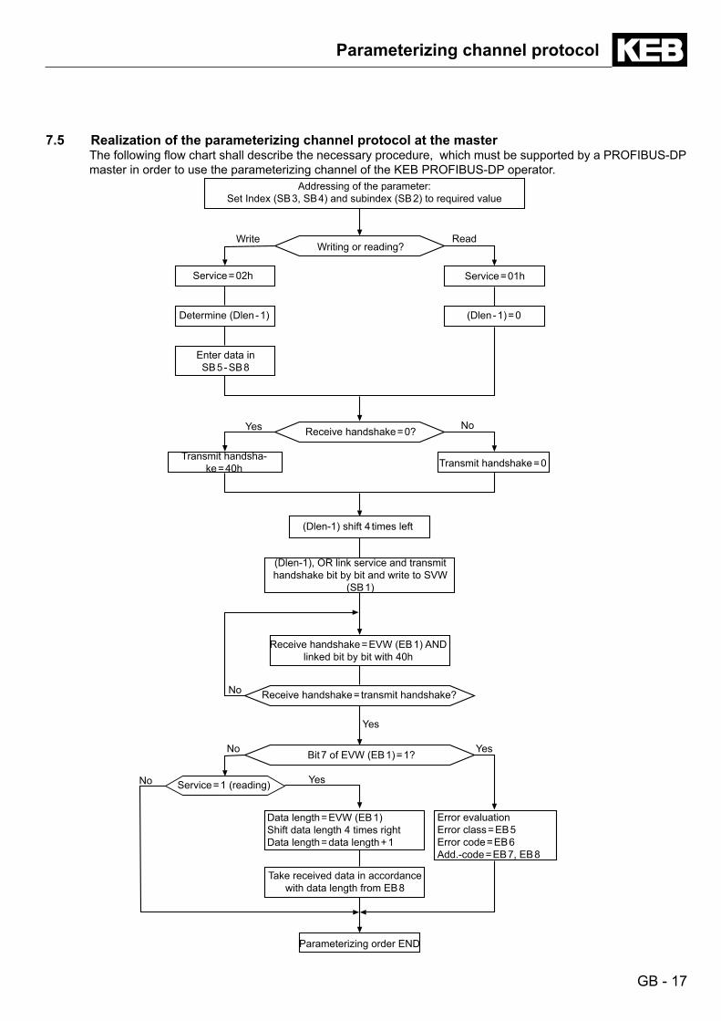
7.5 Realization of the parameterizing channel protocol at the master The following flow chart shall describe the necessary procedure, which must be supported by a PROFIBUS-DP
master in order to use the parameterizing channel of the KEB PROFIBUS-DP operator.
Addressing of the parameter:Set Index (SB 3, SB 4) and subindex (SB 2) to required value
Writing or reading?Write Read
Service = 02h Service = 01h
Determine (Dlen - 1) (Dlen - 1) = 0
Enter data in SB 5 - SB 8
Yes NoReceive handshake = 0?
Transmit handsha-ke = 40h Transmit handshake = 0
(Dlen-1) shift 4 times left
(Dlen-1), OR link service and transmit handshake bit by bit and write to SVW
(SB 1)
Receive handshake = EVW (EB 1) AND linked bit by bit with 40h
Receive handshake = transmit handshake?No
Bit 7 of EVW (EB 1) = 1?No Yes
No YesService = 1 (reading)
Data length = EVW (EB 1)Shift data length 4 times rightData length = data length + 1
Take received data in accordance with data length from EB 8
Error evaluationError class = EB 5Error code = EB 6Add.-code = EB 7, EB 8
Parameterizing order END
Yes
GB - 18
Telegram sequence
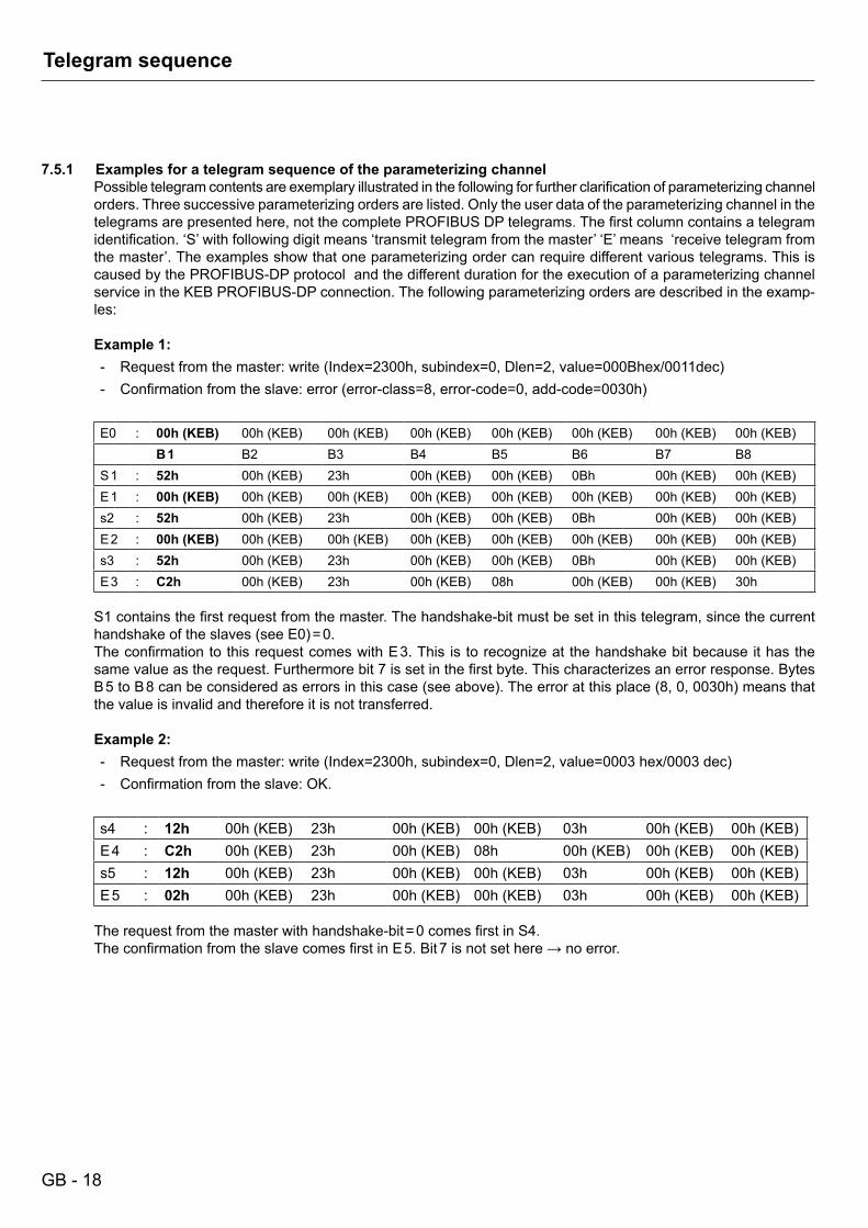
7.5.1 Examples for a telegram sequence of the parameterizing channel Possible telegram contents are exemplary illustrated in the following for further clarification of parameterizing channel
orders. Three successive parameterizing orders are listed. Only the user data of the parameterizing channel in the telegrams are presented here, not the complete PROFIBUS DP telegrams. The first column contains a telegram identification. ‘S’ with following digit means ‘transmit telegram from the master’ ‘E’ means ‘receive telegram from the master’. The examples show that one parameterizing order can require different various telegrams. This is caused by the PROFIBUS-DP protocol and the different duration for the execution of a parameterizing channel service in the KEB PROFIBUS-DP connection. The following parameterizing orders are described in the examp-les:
Example 1:- Request from the master: write (Index=2300h, subindex=0, Dlen=2, value=000Bhex/0011dec)- Confirmation from the slave: error (error-class=8, error-code=0, add-code=0030h)
E0 : 00h(KEB) 00h (KEB) 00h (KEB) 00h (KEB) 00h (KEB) 00h (KEB) 00h (KEB) 00h (KEB)B 1 B2 B3 B4 B5 B6 B7 B8
S 1 : 52h 00h (KEB) 23h 00h (KEB) 00h (KEB) 0Bh 00h (KEB) 00h (KEB)E 1 : 00h(KEB) 00h (KEB) 00h (KEB) 00h (KEB) 00h (KEB) 00h (KEB) 00h (KEB) 00h (KEB)s2 : 52h 00h (KEB) 23h 00h (KEB) 00h (KEB) 0Bh 00h (KEB) 00h (KEB)E 2 : 00h(KEB) 00h (KEB) 00h (KEB) 00h (KEB) 00h (KEB) 00h (KEB) 00h (KEB) 00h (KEB)s3 : 52h 00h (KEB) 23h 00h (KEB) 00h (KEB) 0Bh 00h (KEB) 00h (KEB)E 3 : C2h 00h (KEB) 23h 00h (KEB) 08h 00h (KEB) 00h (KEB) 30h
S1 contains the first request from the master. The handshake-bit must be set in this telegram, since the current handshake of the slaves (see E0) = 0.
The confirmation to this request comes with E 3. This is to recognize at the handshake bit because it has the same value as the request. Furthermore bit 7 is set in the first byte. This characterizes an error response. Bytes B 5 to B 8 can be considered as errors in this case (see above). The error at this place (8, 0, 0030h) means that the value is invalid and therefore it is not transferred.
Example 2:- Request from the master: write (Index=2300h, subindex=0, Dlen=2, value=0003 hex/0003 dec)- Confirmation from the slave: OK.
s4 : 12h 00h (KEB) 23h 00h (KEB) 00h (KEB) 03h 00h (KEB) 00h (KEB)E 4 : C2h 00h (KEB) 23h 00h (KEB) 08h 00h (KEB) 00h (KEB) 00h (KEB)s5 : 12h 00h (KEB) 23h 00h (KEB) 00h (KEB) 03h 00h (KEB) 00h (KEB)E 5 : 02h 00h (KEB) 23h 00h (KEB) 00h (KEB) 03h 00h (KEB) 00h (KEB)
The request from the master with handshake-bit = 0 comes first in S4. The confirmation from the slave comes first in E 5. Bit 7 is not set here → no error.
GB - 19
Telegram sequence
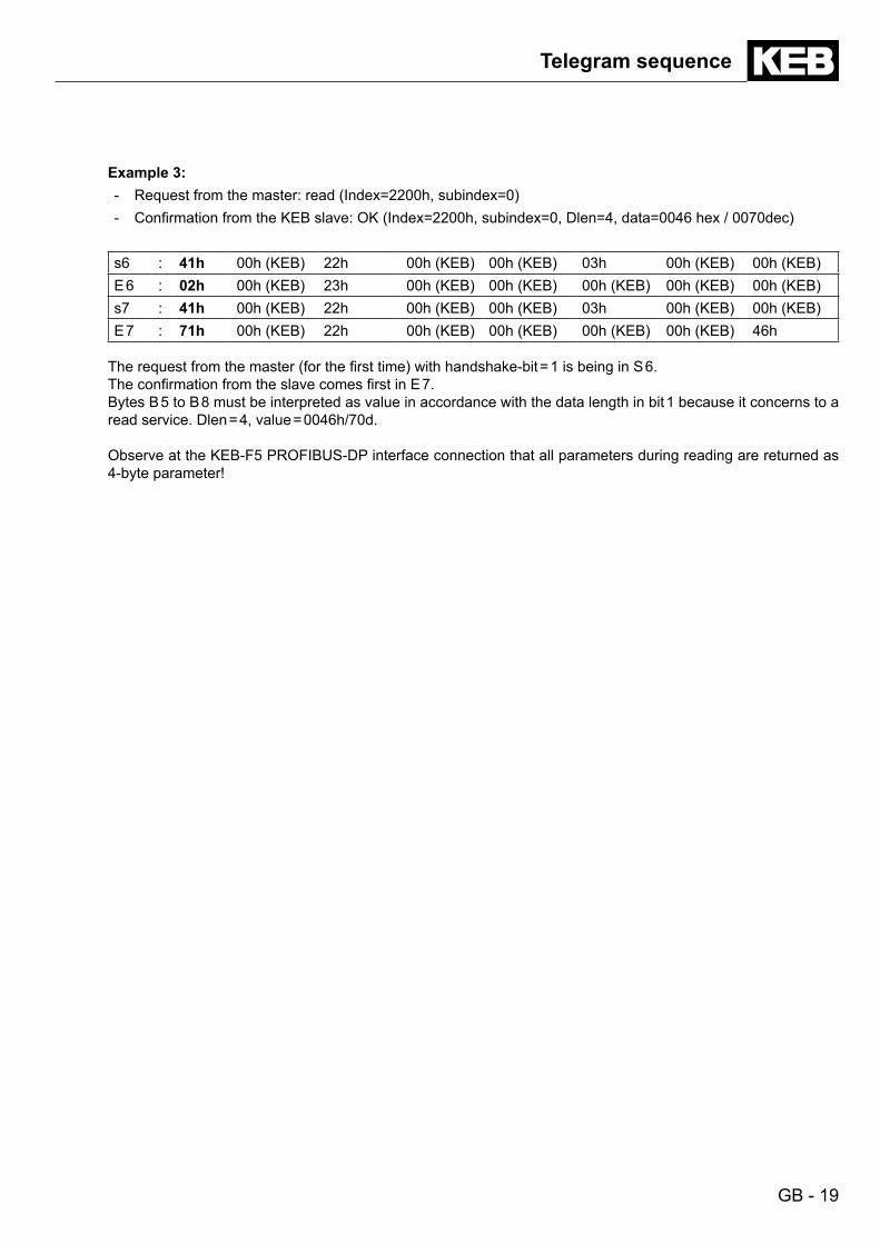
Example 3:- Request from the master: read (Index=2200h, subindex=0)- Confirmation from the KEB slave: OK (Index=2200h, subindex=0, Dlen=4, data=0046 hex / 0070dec)
s6 : 41h 00h (KEB) 22h 00h (KEB) 00h (KEB) 03h 00h (KEB) 00h (KEB)E 6 : 02h 00h (KEB) 23h 00h (KEB) 00h (KEB) 00h (KEB) 00h (KEB) 00h (KEB)s7 : 41h 00h (KEB) 22h 00h (KEB) 00h (KEB) 03h 00h (KEB) 00h (KEB)E 7 : 71h 00h (KEB) 22h 00h (KEB) 00h (KEB) 00h (KEB) 00h (KEB) 46h
The request from the master (for the first time) with handshake-bit = 1 is being in S 6. The confirmation from the slave comes first in E 7. Bytes B 5 to B 8 must be interpreted as value in accordance with the data length in bit 1 because it concerns to a
read service. Dlen = 4, value = 0046h/70d.
Observe at the KEB-F5 PROFIBUS-DP interface connection that all parameters during reading are returned as 4-byte parameter!
GB - 20
8. PROFIBUS-DP Operating Parameters
8.1 Node address The PROFIBUS-DP node address corresponds to the value of the parameter inverter address (SY.06). The default
address of all inverters is 1. SY.06 can be changed via operator keyboard if this address must be changed.
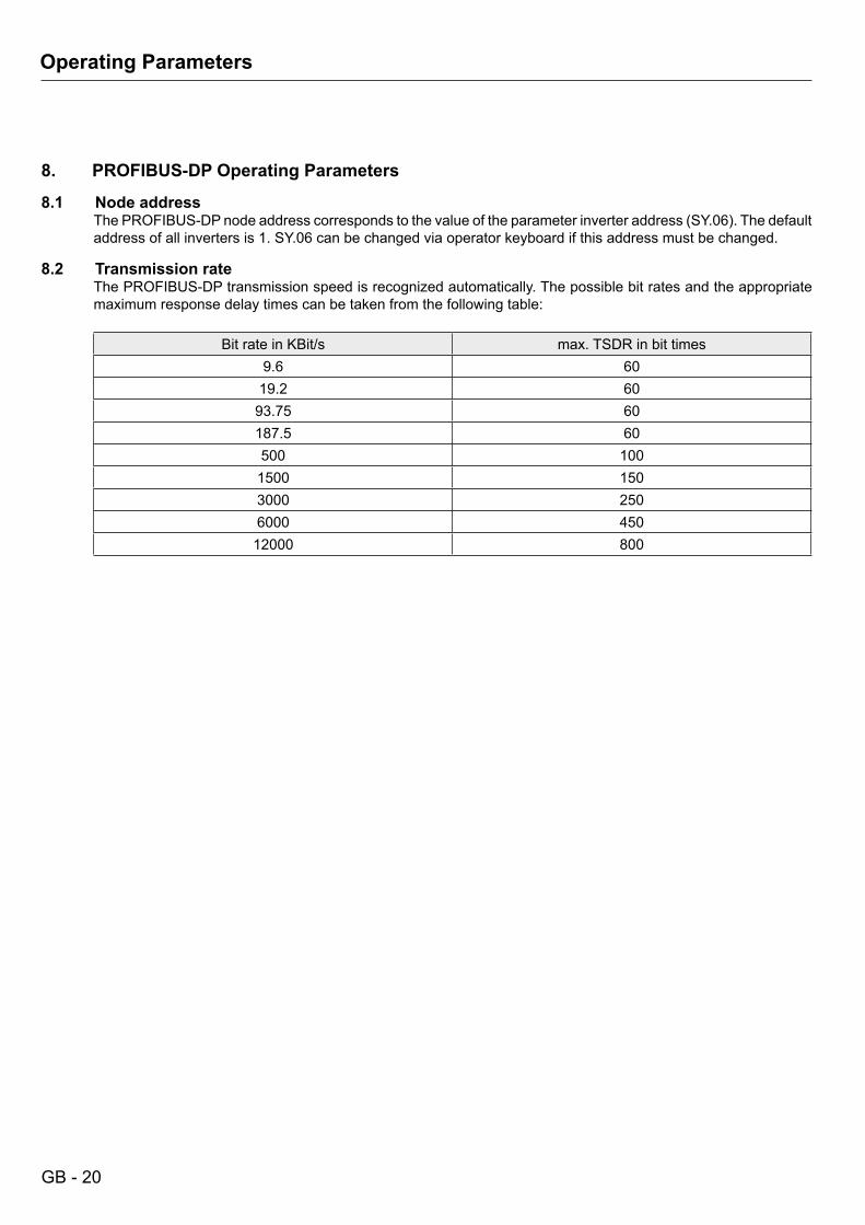
8.2 Transmission rate The PROFIBUS-DP transmission speed is recognized automatically. The possible bit rates and the appropriate
maximum response delay times can be taken from the following table:
Bit rate in KBit/s max. TSDR in bit times9.6 60
19.2 6093.75 60187.5 60500 1001500 1503000 2506000 45012000 800
Operating Parameters

GB - 21
Application Parameters
9. Application Parameters The KEB frequency inverter with PROFIBUS-DP interface connection is characterized by the parameters on the
application level. These parameters are divided in three groups. The classification is preset by the DRIVECOM profile. This prescribes, manufacturer-specific parameters must be inside the index range 2000h...5FFFh. KEB divides this range once more in:- Parameter of the FI control (Index range 2000h...5EFFh).
The following applies to the parameter addressing:Index = parameter address + 2000h (parameter address of the application manual of the FI control). The subindex can be used here as direct setting of the set, if a value not equal to zero is indicated as subin-dex. In this case the value determines bit-coded the addressed set/sets:
B7 = set 7B6 = set 6B5 = set 5B4 = set 4B3 = set 3B2 = set 2B 1 = set 1B0 = set 0
The following must be considered for the simultaneous addressing of several sets :- The value of the parameters is changed in all addressed sets during writing.- The value of the parameter is only returned during reading if the value is equal in all addressed sets. An
error message is returned, if the values are unequal.
If subindex = 0 is preset, then access to the parameter that is defined by the value of the set indicator (Fr.09) is done.
- Configuration parameters of the PROFIBUS-DP interface connection (Index range 5F00h...5FFFh).- Parameters with preset coding by DRIVECOM profile are in index range upto 6000h.
GB - 22
ConfigurationParameters
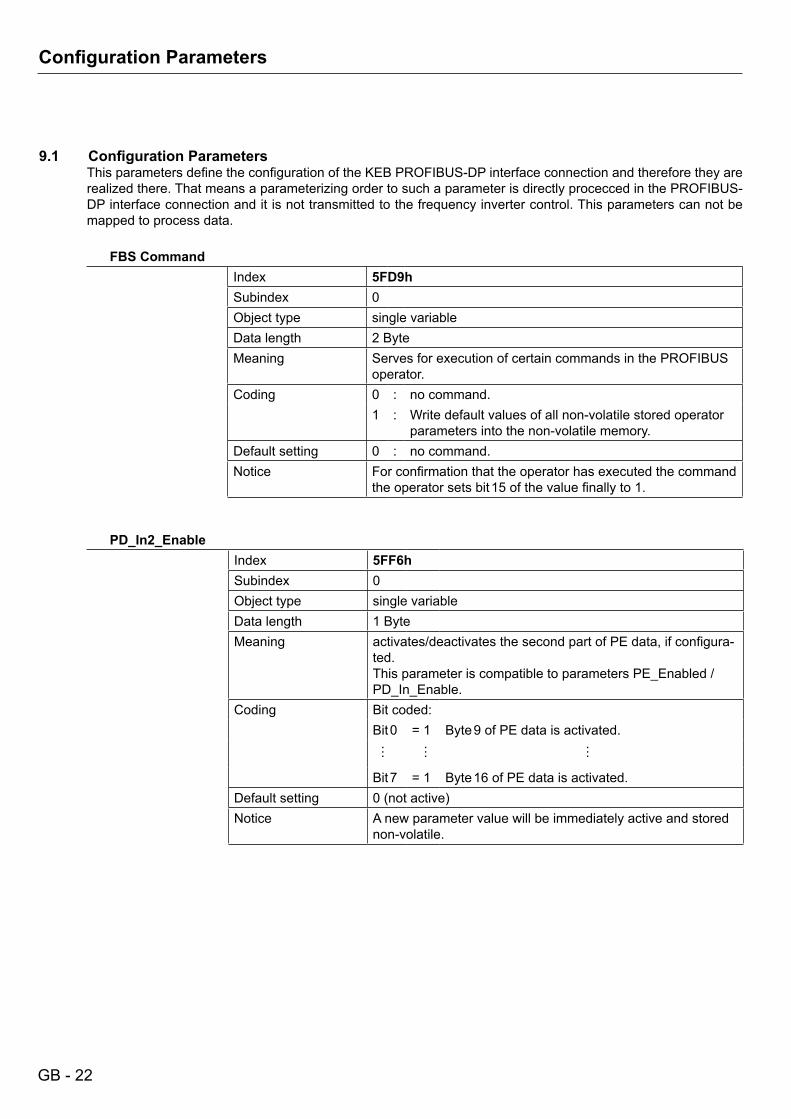
9.1 ConfigurationParameters This parameters define the configuration of the KEB PROFIBUS-DP interface connection and therefore they are
realized there. That means a parameterizing order to such a parameter is directly procecced in the PROFIBUS-DP interface connection and it is not transmitted to the frequency inverter control. This parameters can not be mapped to process data.
FBS CommandIndex 5FD9hSubindex 0Object type single variableData length 2 ByteMeaning Serves for execution of certain commands in the PROFIBUS
operator.Coding 0 : no command.
1 : Write default values of all non-volatile stored operator parameters into the non-volatile memory.
Default setting 0 : no command.Notice For confirmation that the operator has executed the command
the operator sets bit 15 of the value finally to 1.
PD_In2_EnableIndex 5FF6hSubindex 0Object type single variableData length 1 ByteMeaning activates/deactivates the second part of PE data, if configura-
ted.This parameter is compatible to parameters PE_Enabled / PD_In_Enable.
Coding Bit coded:Bit 0 = 1 Byte 9 of PE data is activated.
… … …
Bit 7 = 1 Byte 16 of PE data is activated.Default setting 0 (not active)Notice A new parameter value will be immediately active and stored
non-volatile.
GB - 23
ConfigurationParameters
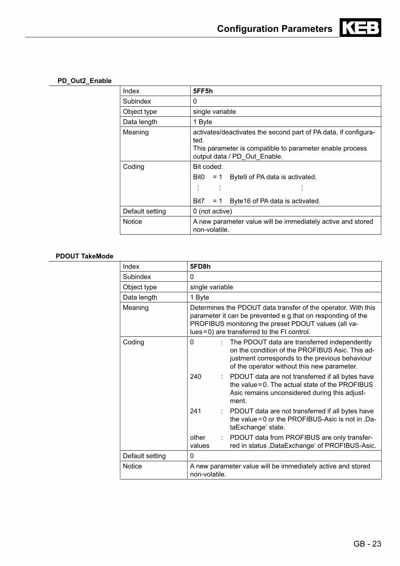
PD_Out2_EnableIndex 5FF5hSubindex 0Object type single variableData length 1 ByteMeaning activates/deactivates the second part of PA data, if configura-
ted.This parameter is compatible to parameter enable process output data / PD_Out_Enable.
Coding Bit coded:Bit0 = 1 Byte9 of PA data is activated.
… … …
Bit7 = 1 Byte16 of PA data is activated.Default setting 0 (not active)Notice A new parameter value will be immediately active and stored
non-volatile.
PDOUT TakeModeIndex 5FD8hSubindex 0Object type single variableData length 1 ByteMeaning Determines the PDOUT data transfer of the operator. With this
parameter it can be prevented e.g.that on responding of the PROFIBUS monitoring the preset PDOUT values (all va-lues = 0) are transferred to the FI control.
Coding 0 : The PDOUT data are transferred independently on the condition of the PROFIBUS Asic. This ad-justment corresponds to the previous behaviour of the operator without this new parameter.
240 : PDOUT data are not transferred if all bytes have the value = 0. The actual state of the PROFIBUS Asic remains unconsidered during this adjust-ment.
241 : PDOUT data are not transferred if all bytes have the value = 0 or the PROFIBUS-Asic is not in ‚Da-taExchange‘ state.
other values
: PDOUT data from PROFIBUS are only transfer-red in status ‚DataExchange‘ of PROFIBUS-Asic.
Default setting 0 Notice A new parameter value will be immediately active and stored
non-volatile.
GB - 24
ConfigurationParameters
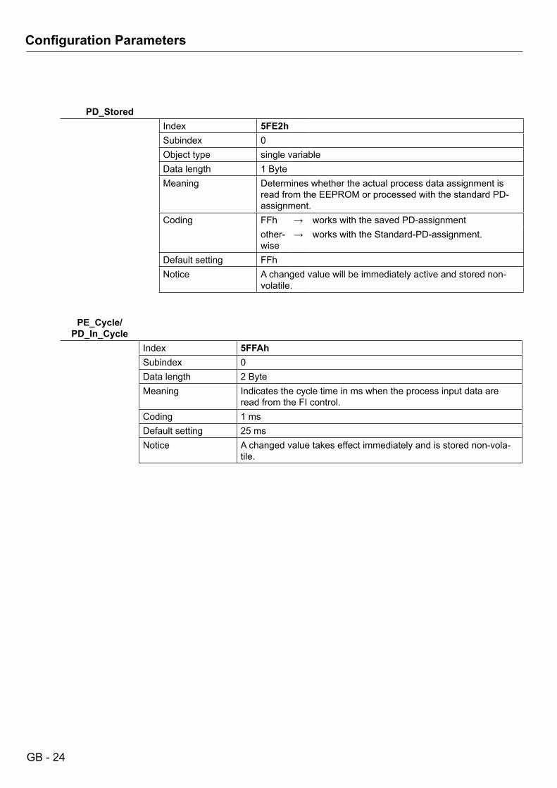
PD_StoredIndex 5FE2hSubindex 0Object type single variableData length 1 ByteMeaning Determines whether the actual process data assignment is
read from the EEPROM or processed with the standard PD-assignment.
Coding FFh → works with the saved PD-assignmentother-wise
→ works with the Standard-PD-assignment.
Default setting FFhNotice A changed value will be immediately active and stored non-
volatile.
PE_Cycle/PD_In_Cycle
Index 5FFAhSubindex 0Data length 2 ByteMeaning Indicates the cycle time in ms when the process input data are
read from the FI control.Coding 1 msDefault setting 25 msNotice A changed value takes effect immediately and is stored non-vola-
tile.
GB - 25
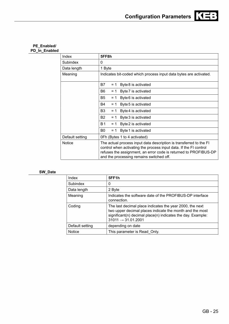
PE_Enabled/ PD_In_Enabled
Index 5FF8hSubindex 0Data length 1 ByteMeaning Indicates bit-coded which process input data bytes are activated.
B7 = 1 Byte 8 is activated
B6 = 1 Byte 7 is activated
B5 = 1 Byte 6 is activated
B4 = 1 Byte 5 is activated
B3 = 1 Byte 4 is activated
B2 = 1 Byte 3 is activated
B 1 = 1 Byte 2 is activated
B0 = 1 Byte 1 is activated
Default setting 0Fh (Bytes 1 to 4 activated)Notice The actual process input data description is transferred to the FI
control when activating the process input data. If the FI control refuses the assignment, an error code is returned to PROFIBUS-DP and the processing remains switched off.
SW_DateIndex 5FF1hSubindex 0Data length 2 ByteMeaning Indicates the software date of the PROFIBUS-DP interface
connection.Coding The last decimal place indicates the year 2000, the next
two upper decimal places indicate the month and the most significant(n) decimal place(n) indicates the day. Example: 31011 → 31.01.2001
Default setting depending on dateNotice This parameter is Read_Only.
ConfigurationParameters

GB - 26
ConfigurationParameters
SW_VersionIndex 5FF0hSubindex 0Data length 2 ByteMeaning Indicates the software version of the PROFIBUS-DP interface
connection.Coding 0.1Default setting depending on versionNotice This parameter is Read_Only.
ValueSwappingIndex 5FF4hSubindex 0Object type single variableData length 1 ByteMeaning Serves for adaption of systems, store the data in intel format
(low byte first). With this parameter the 16 bit and 32 bit data can be changed byte by byte in this sequence. The change can be programmed separately for process data and parame-terizing channel.
Coding Bit coded:Bit 0 =
1Change all 16 bit and 32 bit values in process data
Bit 1 = 1
Change index (16 bit), value (32 bit) in the para-meterizing channel
Bit 2-7 reservedDefault setting 0 (no data change)Notice A new parameter value is immediately stored non-volatile, but
becomes active only after the next switch on.
GB - 27
ConfigurationParameters
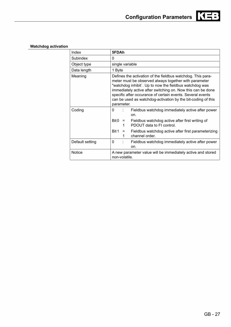
Watchdog activationIndex 5FDAhSubindex 0Object type single variableData length 1 ByteMeaning Defines the activation of the fieldbus watchdog. This para-
meter must be observed always together with parameter "watchdog inhibit`. Up to now the fieldbus watchdog was immediately active after switching on. Now this can be done specific after occurance of certain events. Several events can be used as watchdog-activation by the bit-coding of this parameter.
Coding 0 : Fieldbus watchdog immediately active after power on.
Bit 0 = 1
Fieldbus watchdog active after first writing of PDOUT data to FI control.
Bit 1 = 1
Fieldbus watchdog active after first parameterizing channel order.
Default setting 0 : Fieldbus watchdog immediately active after power on.
Notice A new parameter value will be immediately active and stored non-volatile.
GB - 28
ConfigurationParameters
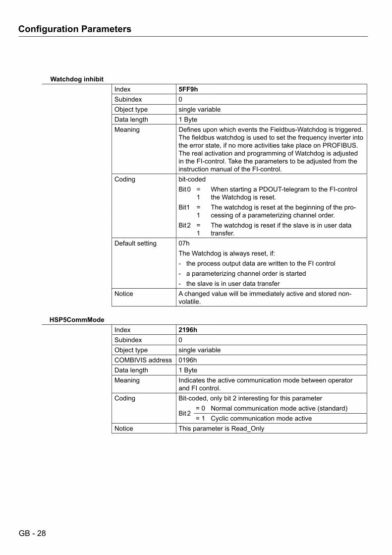
Watchdog inhibitIndex 5FF9hSubindex 0Object type single variableData length 1 ByteMeaning Defines upon which events the Fieldbus-Watchdog is triggered.
The fieldbus watchdog is used to set the frequency inverter into the error state, if no more activities take place on PROFIBUS. The real activation and programming of Watchdog is adjusted in the FI-control. Take the parameters to be adjusted from the instruction manual of the FI-control.
Coding bit-codedBit 0 =
1When starting a PDOUT-telegram to the FI-control the Watchdog is reset.
Bit1 = 1
The watchdog is reset at the beginning of the pro-cessing of a parameterizing channel order.
Bit 2 = 1
The watchdog is reset if the slave is in user data transfer.
Default setting 07hThe Watchdog is always reset, if:- the process output data are written to the FI control- a parameterizing channel order is started- the slave is in user data transfer
Notice A changed value will be immediately active and stored non-volatile.
HSP5CommModeIndex 2196hSubindex 0Object type single variableCOMBIVIS address 0196hData length 1 ByteMeaning Indicates the active communication mode between operator
and FI control.Coding Bit-coded, only bit 2 interesting for this parameter
Bit 2= 0 Normal communication mode active (standard)= 1 Cyclic communication mode active
Notice This parameter is Read_Only
GB - 29
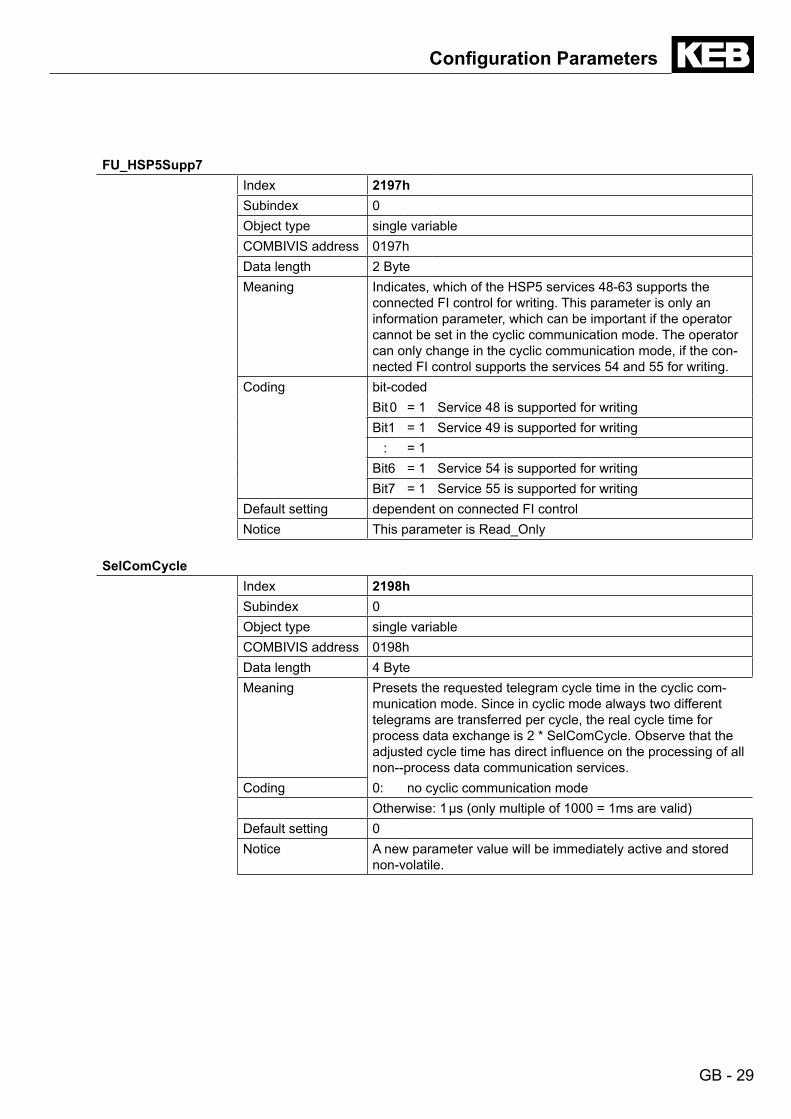
FU_HSP5Supp7Index 2197hSubindex 0Object type single variableCOMBIVIS address 0197hData length 2 ByteMeaning Indicates, which of the HSP5 services 48-63 supports the
connected FI control for writing. This parameter is only an information parameter, which can be important if the operator cannot be set in the cyclic communication mode. The operator can only change in the cyclic communication mode, if the con-nected FI control supports the services 54 and 55 for writing.
Coding bit-codedBit 0 = 1 Service 48 is supported for writingBit1 = 1 Service 49 is supported for writing
: = 1Bit6 = 1 Service 54 is supported for writingBit7 = 1 Service 55 is supported for writing
Default setting dependent on connected FI controlNotice This parameter is Read_Only
SelComCycleIndex 2198hSubindex 0Object type single variableCOMBIVIS address 0198hData length 4 ByteMeaning Presets the requested telegram cycle time in the cyclic com-
munication mode. Since in cyclic mode always two different telegrams are transferred per cycle, the real cycle time for process data exchange is 2 * SelComCycle. Observe that the adjusted cycle time has direct influence on the processing of all non--process data communication services.
Coding 0: no cyclic communication modeOtherwise: 1 μs (only multiple of 1000 = 1ms are valid)
Default setting 0Notice A new parameter value will be immediately active and stored
non-volatile.
ConfigurationParameters
GB - 30
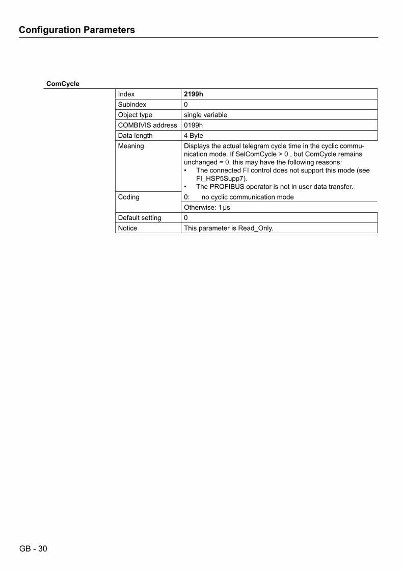
ComCycleIndex 2199hSubindex 0Object type single variableCOMBIVIS address 0199hData length 4 ByteMeaning Displays the actual telegram cycle time in the cyclic commu-
nication mode. If SelComCycle > 0 , but ComCycle remains unchanged = 0, this may have the following reasons:• The connected FI control does not support this mode (see
FI_HSP5Supp7).• The PROFIBUS operator is not in user data transfer.
Coding 0: no cyclic communication modeOtherwise: 1 µs
Default setting 0Notice This parameter is Read_Only.
ConfigurationParameters
GB - 31
DRIVECOMProfileParameters
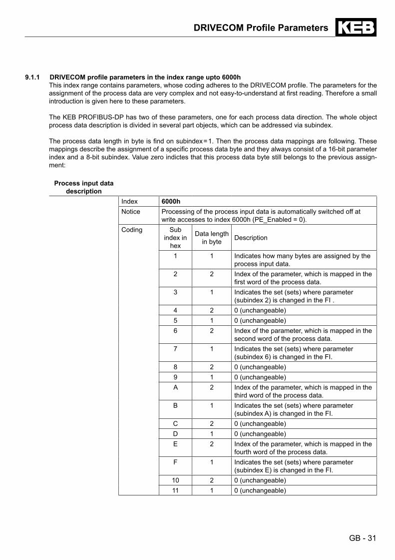
9.1.1 DRIVECOMprofileparametersintheindexrangeupto6000h This index range contains parameters, whose coding adheres to the DRIVECOM profile. The parameters for the
assignment of the process data are very complex and not easy-to-understand at first reading. Therefore a small introduction is given here to these parameters.
The KEB PROFIBUS-DP has two of these parameters, one for each process data direction. The whole object process data description is divided in several part objects, which can be addressed via subindex.
The process data length in byte is find on subindex = 1. Then the process data mappings are following. These mappings describe the assignment of a specific process data byte and they always consist of a 16-bit parameter index and a 8-bit subindex. Value zero indictes that this process data byte still belongs to the previous assign-ment:
Process input data description
Index 6000hNotice Processing of the process input data is automatically switched off at
write accesses to index 6000h (PE_Enabled = 0).Coding Sub
index in hex
Data length in byte Description
1 1 Indicates how many bytes are assigned by the process input data.
2 2 Index of the parameter, which is mapped in the first word of the process data.
3 1 Indicates the set (sets) where parameter (subindex 2) is changed in the FI .
4 2 0 (unchangeable)5 1 0 (unchangeable)6 2 Index of the parameter, which is mapped in the
second word of the process data.7 1 Indicates the set (sets) where parameter
(subindex 6) is changed in the FI.8 2 0 (unchangeable)9 1 0 (unchangeable)A 2 Index of the parameter, which is mapped in the
third word of the process data.B 1 Indicates the set (sets) where parameter
(subindex A) is changed in the FI.C 2 0 (unchangeable)D 1 0 (unchangeable)E 2 Index of the parameter, which is mapped in the
fourth word of the process data.F 1 Indicates the set (sets) where parameter
(subindex E) is changed in the FI.10 2 0 (unchangeable)11 1 0 (unchangeable)
GB - 32
DRIVECOMProfileParameters
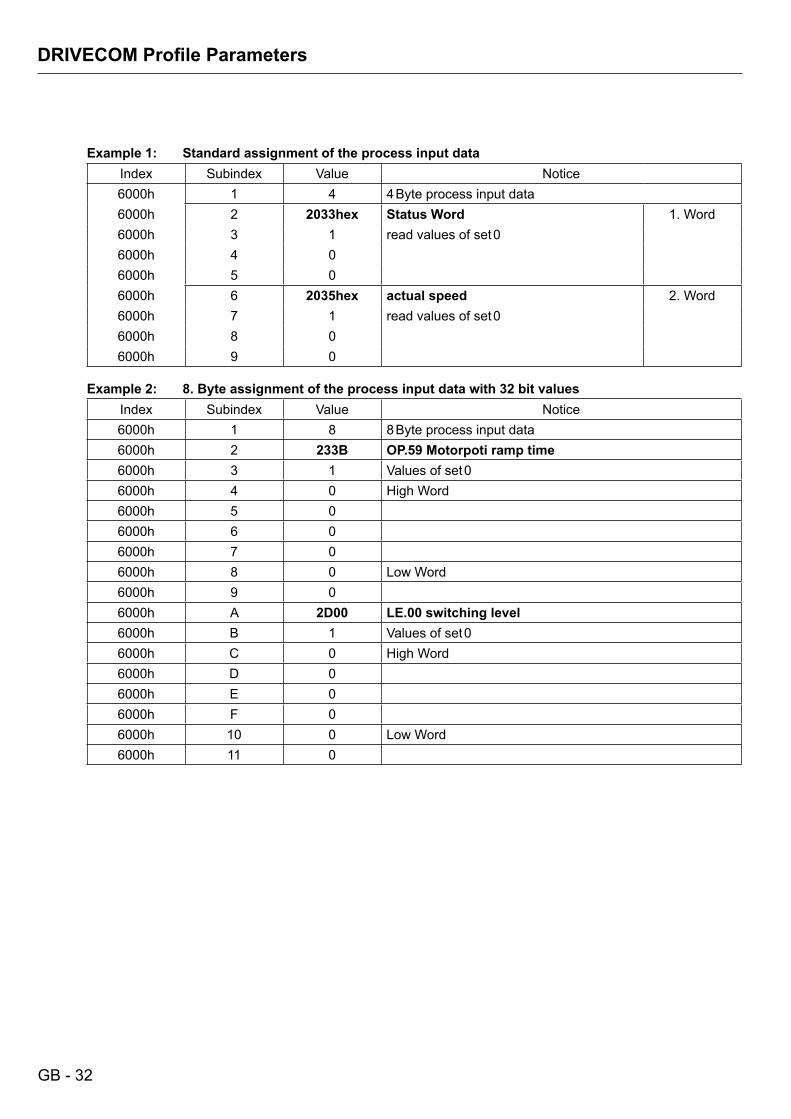
Example 1: Standard assignment of the process input dataIndex Subindex Value Notice6000h 1 4 4 Byte process input data6000h 2 2033hex Status Word 1. Word6000h 3 1 read values of set 06000h 4 06000h 5 06000h 6 2035hex actual speed 2. Word6000h 7 1 read values of set 06000h 8 06000h 9 0
Example 2: 8. Byte assignment of the process input data with 32 bit values
Index Subindex Value Notice6000h 1 8 8 Byte process input data6000h 2 233B OP.59 Motorpoti ramp time6000h 3 1 Values of set 06000h 4 0 High Word6000h 5 06000h 6 06000h 7 06000h 8 0 Low Word6000h 9 06000h A 2D00 LE.00 switching level6000h B 1 Values of set 06000h C 0 High Word6000h D 06000h E 06000h F 06000h 10 0 Low Word6000h 11 0
GB - 33
DRIVECOMProfileParameters
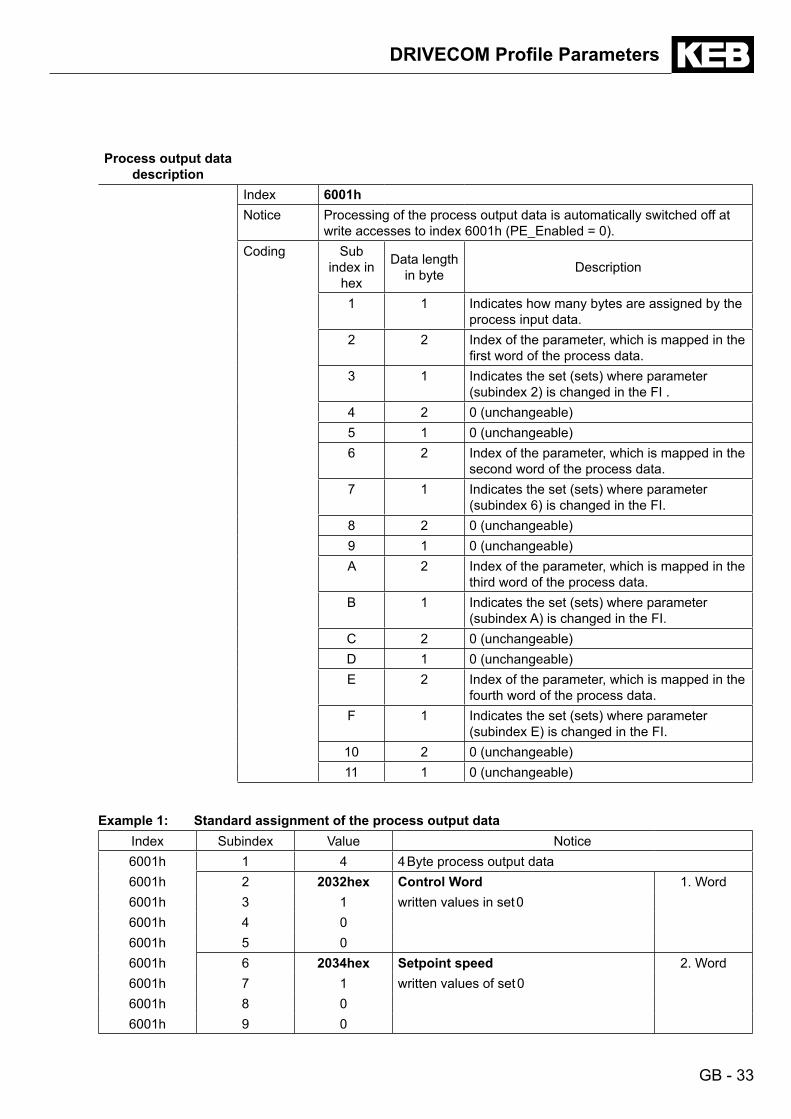
Process output data description
Index 6001hNotice Processing of the process output data is automatically switched off at
write accesses to index 6001h (PE_Enabled = 0).Coding Sub
index in hex
Data length in byte Description
1 1 Indicates how many bytes are assigned by the process input data.
2 2 Index of the parameter, which is mapped in the first word of the process data.
3 1 Indicates the set (sets) where parameter (subindex 2) is changed in the FI .
4 2 0 (unchangeable)5 1 0 (unchangeable)6 2 Index of the parameter, which is mapped in the
second word of the process data.7 1 Indicates the set (sets) where parameter
(subindex 6) is changed in the FI.8 2 0 (unchangeable)9 1 0 (unchangeable)A 2 Index of the parameter, which is mapped in the
third word of the process data.B 1 Indicates the set (sets) where parameter
(subindex A) is changed in the FI.C 2 0 (unchangeable)D 1 0 (unchangeable)E 2 Index of the parameter, which is mapped in the
fourth word of the process data.F 1 Indicates the set (sets) where parameter
(subindex E) is changed in the FI.10 2 0 (unchangeable)11 1 0 (unchangeable)
Example 1: Standard assignment of the process output dataIndex Subindex Value Notice6001h 1 4 4 Byte process output data6001h 2 2032hex Control Word 1. Word6001h 3 1 written values in set 06001h 4 06001h 5 06001h 6 2034hex Setpoint speed 2. Word6001h 7 1 written values of set 06001h 8 06001h 9 0

GB - 34
DRIVECOMProfileParameters
Enable process output data / PD_
Out_EnableIndex 6002hSubindex 0Data length 1 ByteMeaning Indicates bit-coded which process output data bytes are activa-
ted.Coding B7 = 1 Byte 8 is activated
B6 = 1 Byte 7 is activated
B5 = 1 Byte 6 is activated
B4 = 1 Byte 5 is activated
B3 = 1 Byte 4 is activated
B2 = 1 Byte 3 is activated
B 1 = 1 Byte 2 is activated
B0 = 1 Byte 1 is activated
Default setting 0Fh (Bytes 1 to 4 activated)Notice The actual process output data description is transferred to
the FI control when activating the process output data. If the FI control refuses the assignment, an error code is returned to PROFIBUS-DP and the processing remains switched off.
GB - 35
Operator Parameters
10. Access to Operator Parameters
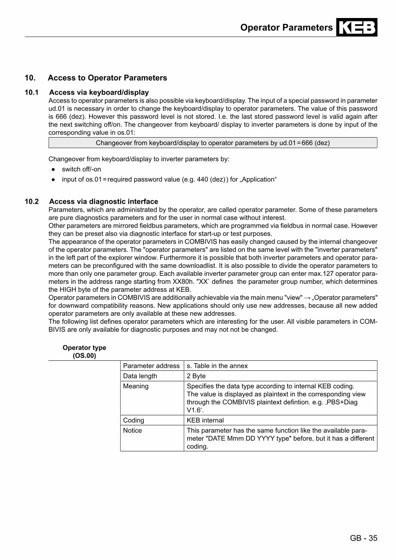
10.1 Access via keyboard/display Access to operator parameters is also possible via keyboard/display. The input of a special password in parameter
ud.01 is necessary in order to change the keyboard/display to operator parameters. The value of this password is 666 (dez). However this password level is not stored. I.e. the last stored password level is valid again after the next switching off/on. The changeover from keyboard/ display to inverter parameters is done by input of the corresponding value in os.01:
Changeover from keyboard/display to operator parameters by ud.01 = 666 (dez) Changeover from keyboard/display to inverter parameters by:
● switch off/-on● input of os.01 = required password value (e.g. 440 (dez) ) for „Application“
10.2 Access via diagnostic interface Parameters, which are administrated by the operator, are called operator parameter. Some of these parameters
are pure diagnostics parameters and for the user in normal case without interest. Other parameters are mirrored fieldbus parameters, which are programmed via fieldbus in normal case. However
they can be preset also via diagnostic interface for start-up or test purposes. The appearance of the operator parameters in COMBIVIS has easily changed caused by the internal changeover
of the operator parameters. The "operator parameters" are listed on the same level with the "inverter parameters" in the left part of the explorer window. Furthermore it is possible that both inverter parameters and operator para-meters can be preconfigured with the same downloadlist. It is also possible to divide the operator parameters to more than only one parameter group. Each available inverter parameter group can enter max.127 operator para-meters in the address range starting from XX80h. "XX` defines the parameter group number, which determines the HIGH byte of the parameter address at KEB.
Operator parameters in COMBIVIS are additionally achievable via the main menu "view" → „Operator parameters" for downward compatibility reasons. New applications should only use new addresses, because all new added operator parameters are only available at these new addresses.
The following list defines operator parameters which are interesting for the user. All visible parameters in COM-BIVIS are only available for diagnostic purposes and may not not be changed.
Operator type (OS.00)
Parameter address s. Table in the annexData length 2 ByteMeaning Specifies the data type according to internal KEB coding.
The value is displayed as plaintext in the corresponding view through the COMBIVIS plaintext defintion. e.g. ‚PBS+Diag V1.6‘.
Coding KEB internalNotice This parameter has the same function like the available para-
meter "DATE Mmm DD YYYY type" before, but it has a different coding.
GB - 36
operator parameters
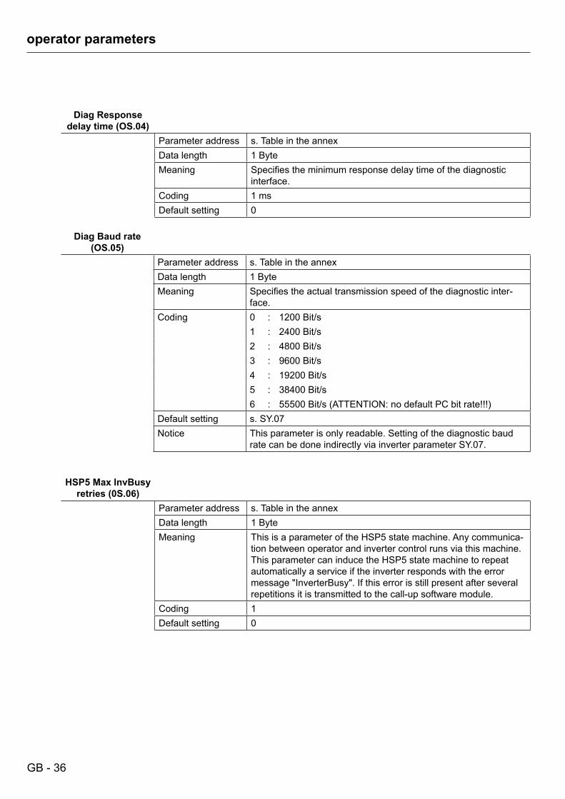
Diag Response delaytime(OS.04)
Parameter address s. Table in the annexData length 1 ByteMeaning Specifies the minimum response delay time of the diagnostic
interface.Coding 1 msDefault setting 0
Diag Baud rate (OS.05)
Parameter address s. Table in the annexData length 1 ByteMeaning Specifies the actual transmission speed of the diagnostic inter-
face.Coding 0 : 1200 Bit/s
1 : 2400 Bit/s2 : 4800 Bit/s3 : 9600 Bit/s4 : 19200 Bit/s5 : 38400 Bit/s6 : 55500 Bit/s (ATTENTION: no default PC bit rate!!!)
Default setting s. SY.07Notice This parameter is only readable. Setting of the diagnostic baud
rate can be done indirectly via inverter parameter SY.07.
HSP5 Max InvBusy retries(0S.06)
Parameter address s. Table in the annexData length 1 ByteMeaning This is a parameter of the HSP5 state machine. Any communica-
tion between operator and inverter control runs via this machine. This parameter can induce the HSP5 state machine to repeat automatically a service if the inverter responds with the error message "InverterBusy". If this error is still present after several repetitions it is transmitted to the call-up software module.
Coding 1Default setting 0
GB - 37
operator parameters
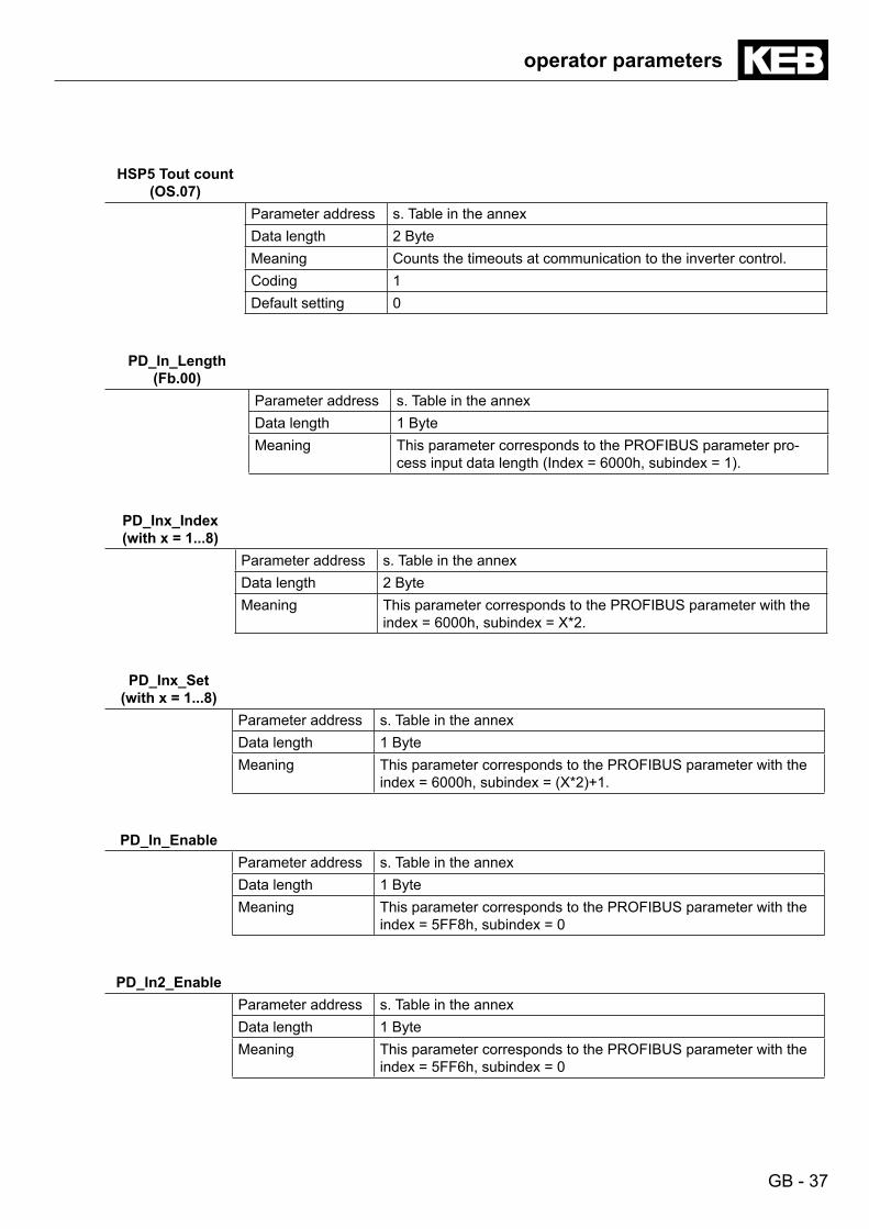
HSP5 Tout count (OS.07)
Parameter address s. Table in the annexData length 2 ByteMeaning Counts the timeouts at communication to the inverter control.Coding 1Default setting 0
PD_In_Length (Fb.00)
Parameter address s. Table in the annexData length 1 ByteMeaning This parameter corresponds to the PROFIBUS parameter pro-
cess input data length (Index = 6000h, subindex = 1).
PD_Inx_Index (withx=1...8)
Parameter address s. Table in the annexData length 2 ByteMeaning This parameter corresponds to the PROFIBUS parameter with the
index = 6000h, subindex = X*2.
PD_Inx_Set(withx=1...8)
Parameter address s. Table in the annexData length 1 ByteMeaning This parameter corresponds to the PROFIBUS parameter with the
index = 6000h, subindex = (X*2)+1.
PD_In_EnableParameter address s. Table in the annexData length 1 ByteMeaning This parameter corresponds to the PROFIBUS parameter with the
index = 5FF8h, subindex = 0
PD_In2_EnableParameter address s. Table in the annexData length 1 ByteMeaning This parameter corresponds to the PROFIBUS parameter with the
index = 5FF6h, subindex = 0
GB - 38
operator parameters
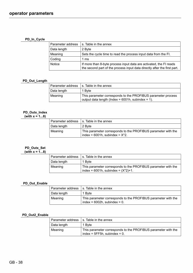
PD_In_CycleParameter address s. Table in the annexData length 2 ByteMeaning Sets the cycle time to read the process input data from the FI.Coding 1 msNotice If more than 8-byte process input data are activated, the FI reads
the second part of the process input data directly after the first part.
PD_Out_LengthParameter address s. Table in the annexData length 1 ByteMeaning This parameter corresponds to the PROFIBUS parameter process
output data length (Index = 6001h, subindex = 1).
PD_Outx_Index (withx=1...8)
Parameter address s. Table in the annexData length 2 ByteMeaning This parameter corresponds to the PROFIBUS parameter with the
index = 6001h, subindex = X*2.
PD_Outx_Set (withx=1...8)
Parameter address s. Table in the annexData length 1 ByteMeaning This parameter corresponds to the PROFIBUS parameter with the
index = 6001h, subindex = (X*2)+1.
PD_Out_EnableParameter address s. Table in the annexData length 1 ByteMeaning This parameter corresponds to the PROFIBUS parameter with the
index = 6002h, subindex = 0.
PD_Out2_EnableParameter address s. Table in the annexData length 1 ByteMeaning This parameter corresponds to the PROFIBUS parameter with the
index = 5FF5h, subindex = 0.
GB - 39
operator parameters
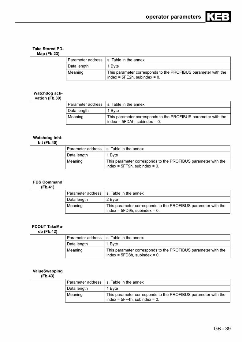
Take Stored PD-Map(Fb.23)
Parameter address s. Table in the annexData length 1 ByteMeaning This parameter corresponds to the PROFIBUS parameter with the
index = 5FE2h, subindex = 0.
Watchdog acti-vation(Fb.39)
Parameter address s. Table in the annexData length 1 ByteMeaning This parameter corresponds to the PROFIBUS parameter with the
index = 5FDAh, subindex = 0.
Watchdog inhi-bit(Fb.40)
Parameter address s. Table in the annexData length 1 ByteMeaning This parameter corresponds to the PROFIBUS parameter with the
index = 5FF9h, subindex = 0.
FBS Command (Fb.41)
Parameter address s. Table in the annexData length 2 ByteMeaning This parameter corresponds to the PROFIBUS parameter with the
index = 5FD9h, subindex = 0.
PDOUT TakeMo-de(Fb.42)
Parameter address s. Table in the annexData length 1 ByteMeaning This parameter corresponds to the PROFIBUS parameter with the
index = 5FD8h, subindex = 0.
ValueSwapping (Fb.43)
Parameter address s. Table in the annexData length 1 ByteMeaning This parameter corresponds to the PROFIBUS parameter with the
index = 5FF4h, subindex = 0.
GB - 40
KEB PROFIBUS-DP Compact
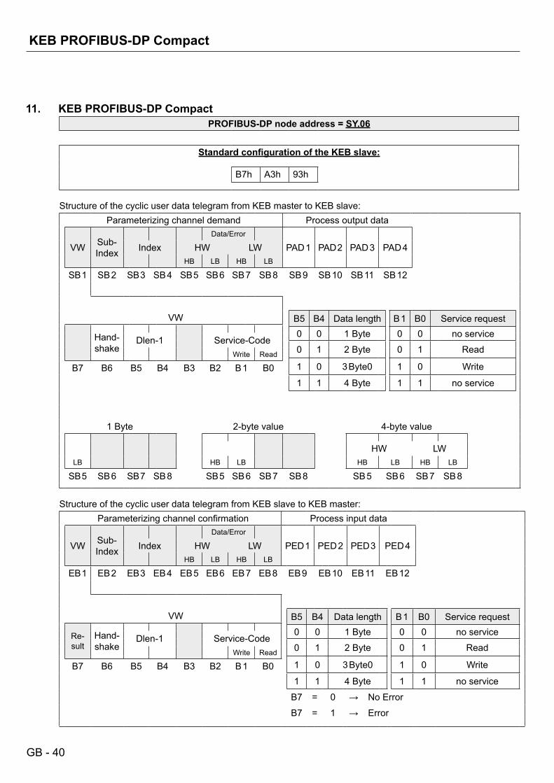
11. KEB PROFIBUS-DP CompactPROFIBUS-DP node address = SY.06
StandardconfigurationoftheKEBslave:
B7h A3h 93h
Structure of the cyclic user data telegram from KEB master to KEB slave:Parameterizing channel demand Process output data
VW Sub-Index
Data/Error
PAD 1 PAD 2 PAD 3 PAD 4Index HW LWHB LB HB LB
SB 1 SB 2 SB 3 SB 4 SB 5 SB 6 SB 7 SB 8 SB 9 SB 10 SB 11 SB 12
VW B5 B4 Data length B 1 B0 Service request
Hand-shake
0 0 1 Byte 0 0 no serviceDlen-1 Service-Code
0 1 2 Byte 0 1 ReadWrite Read
1 0 3 Byte0 1 0 WriteB7 B6 B5 B4 B3 B2 B 1 B01 1 4 Byte 1 1 no service
1 Byte 2-byte value 4-byte value
HW LWLB HB LB HB LB HB LB
SB 5 SB 6 SB 7 SB 8 SB 5 SB 6 SB 7 SB 8 SB 5 SB 6 SB 7 SB 8
Structure of the cyclic user data telegram from KEB slave to KEB master:Parameterizing channel confirmation Process input data
VW Sub-Index
Data/Error
PED 1 PED 2 PED 3 PED 4Index HW LWHB LB HB LB
EB 1 EB 2 EB 3 EB 4 EB 5 EB 6 EB 7 EB 8 EB 9 EB 10 EB 11 EB 12
VW B5 B4 Data length B 1 B0 Service request
Re-sult
Hand-shake
0 0 1 Byte 0 0 no serviceDlen-1 Service-Code
0 1 2 Byte 0 1 ReadWrite Read
1 0 3 Byte0 1 0 WriteB7 B6 B5 B4 B3 B2 B 1 B01 1 4 Byte 1 1 no service
B7 = 0 → No Error
B7 = 1 → Error
GB - 41
Annex
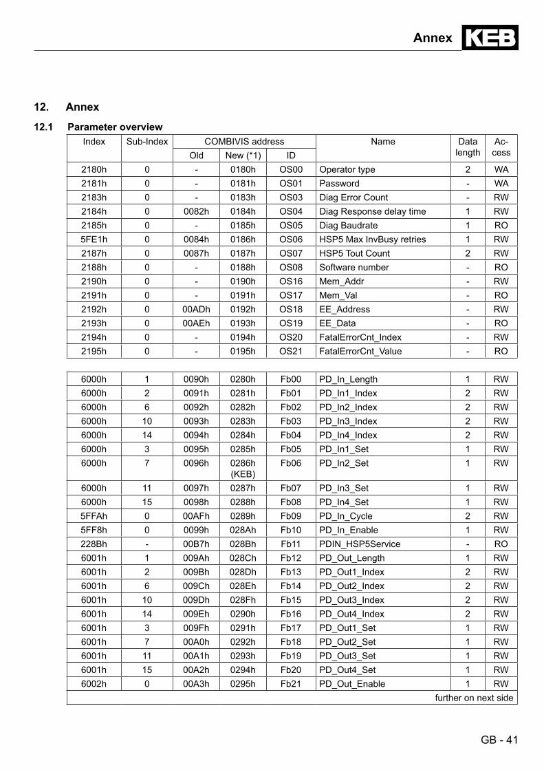
12. Annex
12.1 Parameter overviewIndex Sub-Index COMBIVIS address Name Data
lengthAc-
cessOld New (*1) ID2180h 0 - 0180h OS00 Operator type 2 WA2181h 0 - 0181h OS01 Password - WA2183h 0 - 0183h OS03 Diag Error Count - RW2184h 0 0082h 0184h OS04 Diag Response delay time 1 RW2185h 0 - 0185h OS05 Diag Baudrate 1 RO5FE1h 0 0084h 0186h OS06 HSP5 Max InvBusy retries 1 RW2187h 0 0087h 0187h OS07 HSP5 Tout Count 2 RW2188h 0 - 0188h OS08 Software number - RO2190h 0 - 0190h OS16 Mem_Addr - RW2191h 0 - 0191h OS17 Mem_Val - RO2192h 0 00ADh 0192h OS18 EE_Address - RW2193h 0 00AEh 0193h OS19 EE_Data - RO2194h 0 - 0194h OS20 FatalErrorCnt_Index - RW2195h 0 - 0195h OS21 FatalErrorCnt_Value - RO
6000h 1 0090h 0280h Fb00 PD_In_Length 1 RW6000h 2 0091h 0281h Fb01 PD_In1_Index 2 RW6000h 6 0092h 0282h Fb02 PD_In2_Index 2 RW6000h 10 0093h 0283h Fb03 PD_In3_Index 2 RW6000h 14 0094h 0284h Fb04 PD_In4_Index 2 RW6000h 3 0095h 0285h Fb05 PD_In1_Set 1 RW6000h 7 0096h 0286h
(KEB)Fb06 PD_In2_Set 1 RW
6000h 11 0097h 0287h Fb07 PD_In3_Set 1 RW6000h 15 0098h 0288h Fb08 PD_In4_Set 1 RW5FFAh 0 00AFh 0289h Fb09 PD_In_Cycle 2 RW5FF8h 0 0099h 028Ah Fb10 PD_In_Enable 1 RW228Bh - 00B7h 028Bh Fb11 PDIN_HSP5Service - RO6001h 1 009Ah 028Ch Fb12 PD_Out_Length 1 RW6001h 2 009Bh 028Dh Fb13 PD_Out1_Index 2 RW6001h 6 009Ch 028Eh Fb14 PD_Out2_Index 2 RW6001h 10 009Dh 028Fh Fb15 PD_Out3_Index 2 RW6001h 14 009Eh 0290h Fb16 PD_Out4_Index 2 RW6001h 3 009Fh 0291h Fb17 PD_Out1_Set 1 RW6001h 7 00A0h 0292h Fb18 PD_Out2_Set 1 RW6001h 11 00A1h 0293h Fb19 PD_Out3_Set 1 RW6001h 15 00A2h 0294h Fb20 PD_Out4_Set 1 RW6002h 0 00A3h 0295h Fb21 PD_Out_Enable 1 RW
further on next side
GB - 42
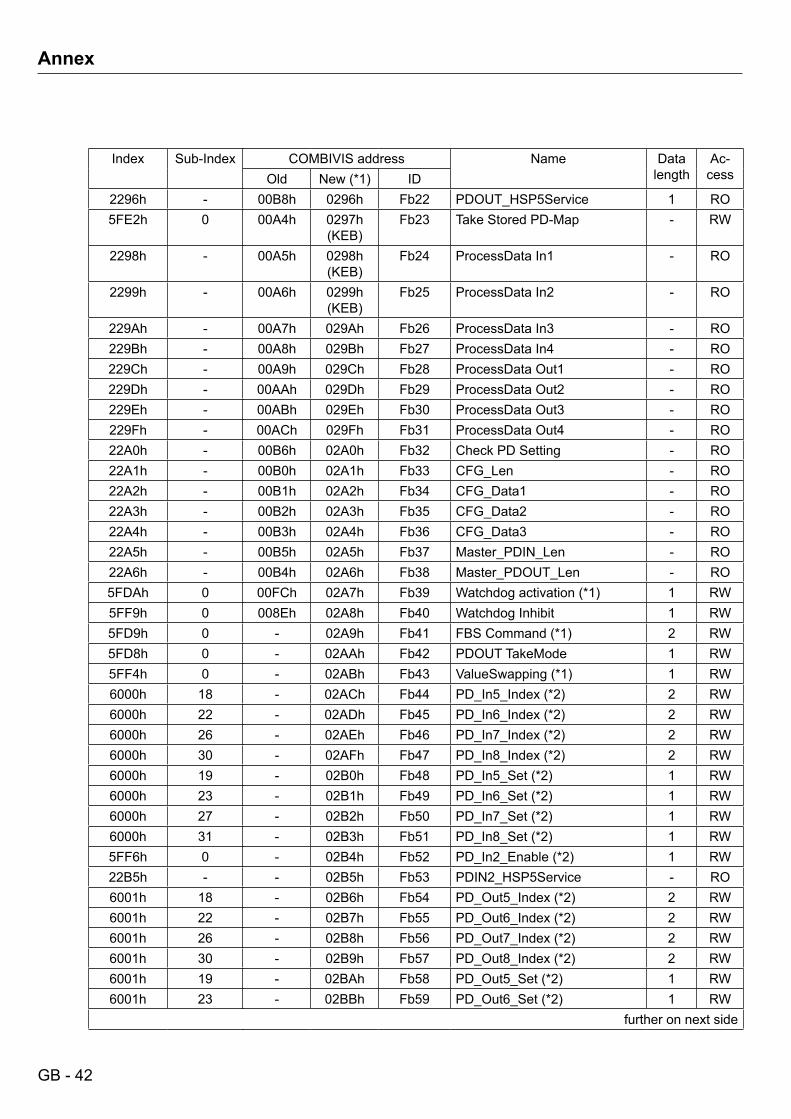
Annex
Index Sub-Index COMBIVIS address Name Data length
Ac-cessOld New (*1) ID
2296h - 00B8h 0296h Fb22 PDOUT_HSP5Service 1 RO5FE2h 0 00A4h 0297h
(KEB)Fb23 Take Stored PD-Map - RW
2298h - 00A5h 0298h (KEB)
Fb24 ProcessData In1 - RO
2299h - 00A6h 0299h (KEB)
Fb25 ProcessData In2 - RO
229Ah - 00A7h 029Ah Fb26 ProcessData In3 - RO229Bh - 00A8h 029Bh Fb27 ProcessData In4 - RO229Ch - 00A9h 029Ch Fb28 ProcessData Out1 - RO229Dh - 00AAh 029Dh Fb29 ProcessData Out2 - RO229Eh - 00ABh 029Eh Fb30 ProcessData Out3 - RO229Fh - 00ACh 029Fh Fb31 ProcessData Out4 - RO22A0h - 00B6h 02A0h Fb32 Check PD Setting - RO22A1h - 00B0h 02A1h Fb33 CFG_Len - RO22A2h - 00B1h 02A2h Fb34 CFG_Data1 - RO22A3h - 00B2h 02A3h Fb35 CFG_Data2 - RO22A4h - 00B3h 02A4h Fb36 CFG_Data3 - RO22A5h - 00B5h 02A5h Fb37 Master_PDIN_Len - RO22A6h - 00B4h 02A6h Fb38 Master_PDOUT_Len - RO5FDAh 0 00FCh 02A7h Fb39 Watchdog activation (*1) 1 RW5FF9h 0 008Eh 02A8h Fb40 Watchdog Inhibit 1 RW5FD9h 0 - 02A9h Fb41 FBS Command (*1) 2 RW5FD8h 0 - 02AAh Fb42 PDOUT TakeMode 1 RW5FF4h 0 - 02ABh Fb43 ValueSwapping (*1) 1 RW6000h 18 - 02ACh Fb44 PD_In5_Index (*2) 2 RW6000h 22 - 02ADh Fb45 PD_In6_Index (*2) 2 RW6000h 26 - 02AEh Fb46 PD_In7_Index (*2) 2 RW6000h 30 - 02AFh Fb47 PD_In8_Index (*2) 2 RW6000h 19 - 02B0h Fb48 PD_In5_Set (*2) 1 RW6000h 23 - 02B1h Fb49 PD_In6_Set (*2) 1 RW6000h 27 - 02B2h Fb50 PD_In7_Set (*2) 1 RW6000h 31 - 02B3h Fb51 PD_In8_Set (*2) 1 RW5FF6h 0 - 02B4h Fb52 PD_In2_Enable (*2) 1 RW22B5h - - 02B5h Fb53 PDIN2_HSP5Service - RO6001h 18 - 02B6h Fb54 PD_Out5_Index (*2) 2 RW6001h 22 - 02B7h Fb55 PD_Out6_Index (*2) 2 RW6001h 26 - 02B8h Fb56 PD_Out7_Index (*2) 2 RW6001h 30 - 02B9h Fb57 PD_Out8_Index (*2) 2 RW6001h 19 - 02BAh Fb58 PD_Out5_Set (*2) 1 RW6001h 23 - 02BBh Fb59 PD_Out6_Set (*2) 1 RW
further on next side
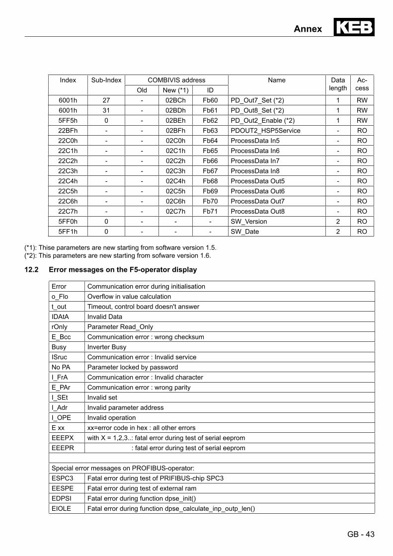
GB - 43
Index Sub-Index COMBIVIS address Name Data length
Ac-cessOld New (*1) ID
6001h 27 - 02BCh Fb60 PD_Out7_Set (*2) 1 RW6001h 31 - 02BDh Fb61 PD_Out8_Set (*2) 1 RW5FF5h 0 - 02BEh Fb62 PD_Out2_Enable (*2) 1 RW22BFh - - 02BFh Fb63 PDOUT2_HSP5Service - RO22C0h - - 02C0h Fb64 ProcessData In5 - RO22C1h - - 02C1h Fb65 ProcessData In6 - RO22C2h - - 02C2h Fb66 ProcessData In7 - RO22C3h - - 02C3h Fb67 ProcessData In8 - RO22C4h - - 02C4h Fb68 ProcessData Out5 - RO22C5h - - 02C5h Fb69 ProcessData Out6 - RO22C6h - - 02C6h Fb70 ProcessData Out7 - RO22C7h - - 02C7h Fb71 ProcessData Out8 - RO5FF0h 0 - - - SW_Version 2 RO5FF1h 0 - - - SW_Date 2 RO
(*1): Thise parameters are new starting from software version 1.5.(*2): This parameters are new starting from sofware version 1.6. 12.2 Error messages on the F5-operator display
Error Communication error during initialisationo_Flo Overflow in value calculationt_out Timeout, control board doesn't answerIDAtA Invalid DatarOnly Parameter Read_OnlyE_Bcc Communication error : wrong checksumBusy Inverter BusyISruc Communication error : Invalid serviceNo PA Parameter locked by passwordI_FrA Communication error : Invalid characterE_PAr Communication error : wrong parityI_SEt Invalid setI_Adr Invalid parameter addressI_OPE Invalid operationE xx xx=error code in hex : all other errorsEEEPX with X = 1,2,3..: fatal error during test of serial eepromEEEPR : fatal error during test of serial eeprom
Special error messages on PROFIBUS-operator:ESPC3 Fatal error during test of PRIFIBUS-chip SPC3EESPE Fatal error during test of external ramEDPSI Fatal error during function dpse_init()EIOLE Fatal error during function dpse_calculate_inp_outp_len()
Annex
GB - 44
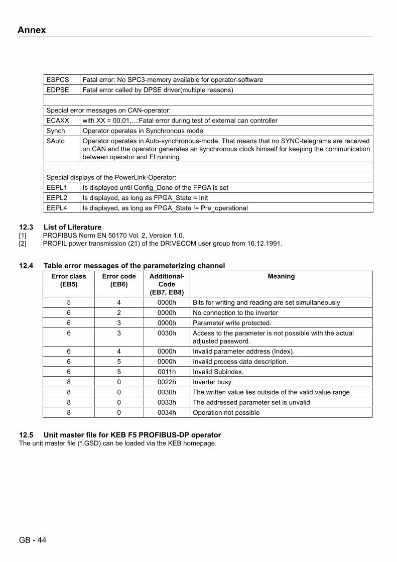
ESPCS Fatal error: No SPC3-memory available for operator-softwareEDPSE Fatal error called by DPSE driver(multiple reasons)
Special error messages on CAN-operator:ECAXX with XX = 00,01,...:Fatal error during test of external can controllerSynch Operator operates in Synchronous modeSAuto Operator operates in Auto-synchronous-mode. That means that no SYNC-telegrams are received
on CAN and the operator generates an synchronous clock himself for keeping the communication between operator and FI running.
Special displays of the PowerLink-Operator:EEPL1 Is displayed until Config_Done of the FPGA is setEEPL2 Is displayed, as long as FPGA_State = InitEEPL4 Is displayed, as long as FPGA_State != Pre_operational
12.3 List of Literature[1] PROFIBUS Norm EN 50170 Vol. 2, Version 1.0.[2] PROFIL power transmission (21) of the DRIVECOM user group from 16.12.1991.
12.4 Table error messages of the parameterizing channelError class
(EB5)Error code
(EB6)Additional-
Code(EB7,EB8)
Meaning
5 4 0000h Bits for writing and reading are set simultaneously6 2 0000h No connection to the inverter6 3 0000h Parameter write protected.6 3 0030h Access to the parameter is not possible with the actual
adjusted password.6 4 0000h Invalid parameter address (Index).6 5 0000h Invalid process data description.6 5 0011h Invalid Subindex.8 0 0022h Inverter busy8 0 0030h The written value lies outside of the valid value range8 0 0033h The addressed parameter set is unvalid8 0 0034h Operation not possible
12.5 UnitmasterfileforKEBF5PROFIBUS-DPoperatorThe unit master file (*.GSD) can be loaded via the KEB homepage.
Annex

Belgien | KEB Automation KGHerenveld 2 9500 Geraardsbergen BelgienTel: +32 544 37860 Fax: +32 544 37898E-Mail: [email protected] Internet: www.keb.de
Brasilien | KEB SOUTH AMERICA - Regional ManagerRua Dr. Omar Pacheco Souza Riberio, 70 CEP 13569-430 Portal do Sol, São Carlos BrasilienTel: +55 16 31161294 E-Mail: [email protected]
P.R. China | KEB Power Transmission Technology (Shanghai) Co. Ltd.No. 435 QianPu Road Chedun Town Songjiang District201611 Shanghai P.R. ChinaTel: +86 21 37746688 Fax: +86 21 37746600E-Mail: [email protected] Internet: www.keb.cn
Deutschland | StammsitzKEB Automation KGSüdstraße 38 32683 Barntrup DeutschlandTelefon +49 5263 401-0 Telefax +49 5263 401-116Internet: www.keb.de E-Mail: [email protected]
Deutschland | GetriebemotorenwerkKEB Antriebstechnik GmbHWildbacher Straße 5 08289 Schneeberg DeutschlandTelefon +49 3772 67-0 Telefax +49 3772 67-281Internet: www.keb-drive.de E-Mail: [email protected]
Frankreich | Société Française KEB SASUZ.I. de la Croix St. Nicolas 14, rue Gustave Eiffel94510 La Queue en Brie FrankreichTel: +33 149620101 Fax: +33 145767495E-Mail: [email protected] Internet: www.keb.fr
Großbritannien | KEB (UK) Ltd. 5 Morris Close Park Farm Indusrial EstateWellingborough, Northants, NN8 6 XF GroßbritannienTel: +44 1933 402220 Fax: +44 1933 400724E-Mail: [email protected] Internet: www.keb.co.uk
Italien | KEB Italia S.r.l. UnipersonaleVia Newton, 2 20019 Settimo Milanese (Milano) ItalienTel: +39 02 3353531 Fax: +39 02 33500790E-Mail: [email protected] Internet: www.keb.it
Japan | KEB Japan Ltd. 15 - 16, 2 - Chome, Takanawa Minato-ku Tokyo 108 - 0074 JapanTel: +81 33 445-8515 Fax: +81 33 445-8215E-Mail: [email protected] Internet: www.keb.jp
Österreich | KEB Antriebstechnik Austria GmbHRitzstraße 8 4614 Marchtrenk ÖsterreichTel: +43 7243 53586-0 Fax: +43 7243 53586-21E-Mail: [email protected] Internet: www.keb.at
Russische Föderation | KEB RUS Ltd.Lesnaya str, house 30 Dzerzhinsky MO140091 Moscow region Russische FöderationTel: +7 495 6320217 Fax: +7 495 6320217E-Mail: [email protected] Internet: www.keb.ru
Südkorea | KEB Automation KGRoom 1709, 415 Missy 2000 725 Su Seo DongGangnam Gu 135- 757 Seoul Republik KoreaTel: +82 2 6253 6771 Fax: +82 2 6253 6770E-Mail: [email protected]
Spanien | KEB Automation KGc / Mitjer, Nave 8 - Pol. Ind. LA MASIA08798 Sant Cugat Sesgarrigues (Barcelona) SpanienTel: +34 93 8970268 Fax: +34 93 8992035 E-Mail: [email protected]
USA | KEB America, Inc5100 Valley Industrial Blvd. South Shakopee, MN 55379 USATel: +1 952 2241400 Fax: +1 952 2241499E-Mail: [email protected] Internet: www.kebamerica.com