com www . electricalpartmanuals · 2011-09-12 · ment is designed, manufactured and tested to nema...
TRANSCRIPT

www . El
ectric
alPar
tMan
uals
. com
www . El
ectric
alPar
tMan
uals
. com

Description Introduction
Table of Contents
Quick Selector Breaker I Trip Combinations ................... .
Quick Selector Replacement Breakers
Page 2 3
Breaker I Trip Combinations . . . . . . . . . . . . . . . . . . . . . . . . . . . . 4
Breaker Designations Legend . . . . . . . . . . . . . . . . . . . . . . . . . . . . . . 5
Type AKA Breaker Features and Characteristics
- Manual Operation . . . . . . . . . . . . . . . . . . . . . . . . . . . . . . . . . . 6
-Electrical Operation . . . . . . . . . . . . . . . . . . . . . . . . . . . . . . . . 7
Type AKRU Breakers . . . . . . . . . . . . . . . . . . . . . . . . . . . . . . . . . . . . . 8
Enclosures and Mountings . . . . . . . . . . . . . . . . . . . . . . . . . . . . . . . . . 9-11
MicroVersaT rip® RMS-9 Devices ............................ 12-13
Trip Devices
-Tripping Functions .................................. 14-21
-EC Trip Devices DC Applications ....................... 22
Accessories ............................................ 23-25
- OEM Substructure ................................. 26-27
Ratings . . . . . . . . . . . . . . . . . . . . . . . . . . . . . . . . . . . . . . . . . . . . . . . . 28
Derating Factors ......................................... 29
MicroVersaT rip® RMS-9 Current Sensor Ratios ................ 30
AKRU Fuses ............................................ 31
Electrical Characteristics -AKR-30 S ......................................... 32-33
-AKR-30150/T50 .................................... 34-35
-AKR-7511 00 ....................................... 36-37
Wiring Diagrams ......................................... 38
T ime Current Tripping Characteristics ......................... 39
T ime Current Curves ..................... , ............... 40-45
Outline Drawings ........................................ 46-52
Outline Dimension Drawing Numbers ......................... 53
Weights and Formulas .................................... 54
Repetitive Duty .......................................... 55
Transformer Short Circuit Current Curves ...................... 56-58
Standards and References ................................. 59 Guide Form Specifications .............................. 60 Other AKA Circuit Breaker Publications .................... 61
www . El
ectric
alPar
tMan
uals
. com
www . El
ectric
alPar
tMan
uals
. com

The General Electric line of Type AKR Low Voltage Power Circuit Breakers (LVPCB) are intended for use in commercial, industrial, and util ity applications. Built to withstand intense service conditions, these circuit breakers provide for the ultimate in system selectivity due to their short time
AKR-75
AKR-30S
2
capabilities. These breakers are UL l isted to ANSI standards for low voltage power circuit breakers. The AKR breaker consists of five frame sizes: AKR-308, -30H, AKR-50, AKRT-50, AKR-75 and AKR-1 00; 800 through 4000 Amperes with short circuit ratings through 200,000 Amperes.
AKR-50
,'\KR-30H www . El
ectric
alPar
tMan
uals
. com
www . El
ectric
alPar
tMan
uals
. com

Breaker Solid State Type Trip Device
AKR-30S 800
AKR-30, 30H 800
AKR-50, -50H 1 600
AKRT-50H 2000
AKR-75 3200
AKR-100 4000
Frame Size
(Am s
800
2000
4000
6000
uick Selector Breaker Trip
Con:b1nations
250Vdc Electromechanical
Trip Device
A JJJ
f.-
3
www . El
ectric
alPar
tMan
uals
. com
www . El
ectric
alPar
tMan
uals
. com

Quick Selector Repl acement Breakers Breaker 1 Trip Device Combinations
Table 4.2 Ampere Ratings and Overcurrent Trip Devices
600V ac 50 /60 Hz
Breaker Solid State Type Trip Device
AK-25 600
AKS-50 1 600
AKST-50 2000
AKR-75 3000
AKR-100 4000
4
Frame Size
(Am s
600
2000
4000
6000
250Vdc
Electromechanical Trip Device
www . El
ectric
alPar
tMan
uals
. com
www . El
ectric
alPar
tMan
uals
. com

Code
AK
AKS
General Type
rl LJj
Old style LVPCB
AKR replacement for AK-50, AKJ-50
AKST AKRT replacement for AKT-50, AKJT-50
AKSU AKRU replacement for AKU-50, AKJU-50
AKR
AKRT
AKRU
AKU
New style LVPCB
2000A frame
Integrally fused version of AKR-30/50
Integrally fused version of AK-25/50
Code
2
3®
4®
5®
60
7
8
N
Trip Device T ype
EC
Power Sensor
ECS
SST
MicroVersaTrip
MicroVersaTrip® RMS-9
Epic Micro Versa Trip rM
Non-automatic
® Discontinued
Example of Nameplate Designation
Mic roVersa - 800A AKR Trip F rame Type Device Size
� t t 8 [l] �
For Draw Out Substructure
Mounting
Code
Blank
A
8
c
D
s
w
F
Breaker Designations Legend
\0 D � �1 .....
Code Frame Size in Amperes (}) ac de
25 600 600
30S 800 -
30, 800 800
30H
50, 1600, 2000 2000
SOH
75 3200 4000
100 4000 6000 <IJ SuffiX D IS aff1xed to AKR des1gnat1ons
to identify non-automatic de models, e.g. AKR-NB-300
Mounting Type
Draw out AKD Switchgear
Draw out AKD-5/6 Switchgear
Draw out AKR OEM Substructure
Draw out AKD-6 Switchgear (AKR-75/100 only)
Draw out AKD-8 Switchgear and OEM Substructure
Stationary
33" Wide Stationary (AKR-100 only)
OEM Substructure AKR-75/100 only)
5
www . El
ectric
alPar
tMan
uals
. com
www . El
ectric
alPar
tMan
uals
. com
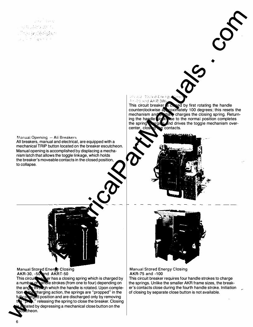
Manual Openmg - AH Breakers All breakers, manual and electrical, are equipped with a mechanical TRIP button located on the breaker escutcheon. Manual opening is accomplished by displacing a mechanism latch that allows the toggle linkage, which holds the breaker's moveable contacts in the closed position, to collapse.
Manual Stored Energy Closing AKR-30, -50 and AKRT-50 This circuit breaker has a closing spring which is charged by a number of handle strokes (from one to four) depending on the angle through which the handle is rotated. Upon completion of the charging action, the springs are "propped" in the fully charged position and are discharged only by removing the "prop," releasing the spring to close the breaker. Closing is initiated by depressing a mechanical close button on the escutcheon.
6
This circuit breaker is closed by first rotating the handle counterclockwise approximately 1 00 degrees; this resets the mechanism and partially charges the closing spring. Returning the handle clockwise to the normal position completes the spring charging and drives the toggle mechanism overcenter, closing the contacts.
Manual Stored Energy Closing AKR-75 and -100 This circuit breaker requires four handle strokes to charge the springs. Un like the smaller AKR frame sizes, the breaker's contacts close during the fourth handle stroke. Initiation of closing by separate close button is not available.
www . El
ectric
alPar
tMan
uals
. com
www . El
ectric
alPar
tMan
uals
. com

::Jectrical Opening All breakers, manual and electrical, are equipped with a mechanical TRIP button located on the breaker escutcheon. Electrical breakers include a shunt trip device for remote opening.
Electrical Stored Energy
AKR-30. -50, -75 & 100 This electrically operated breaker utilizes a motor to automatically keep the closing springs in a charged state. Whenever the control solenoid is energized, its operation releases the closing springs, closing the breaker contacts. (For typical electrical circuit see pg. 38)
Electrical Storeti f.ne�gy
-\K-25 and AKRiU)<30S
Features and Characteristics �lectrical Ooerat1on
This electrically operated breaker closes whenever the closing solenoid coil is energized. This causes an upward movement of the solenoid armature which charges the springs to a predetermined over-center point for closing. (For typical electrical circuit see pg. 38.)
The initiation of the closing operation for both of the above types of breakers is by closing of a contact of a remote switch, relay or a close button in the front escutcheon if the breaker is so equipped. The breakers control schemes have an antipump feature which allows only one closure of the breaker for a single operation of the closing contact no matter how long the contact may be held closed . This prevents the repeated operations that would ensue if one of the automatic trip devices was activated at the time of closing. A manual closing handle is provided for maintenance purposes. All electrically operated breakers close within five cycles.
7
www . El
ectric
alPar
tMan
uals
. com
www . El
ectric
alPar
tMan
uals
. com
Type AKRU Breakers
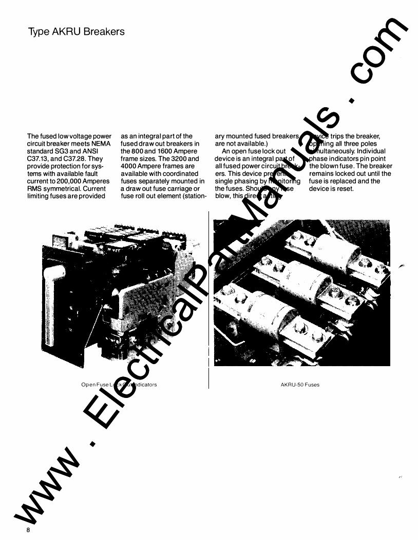
The fused low voltage power drouHbffia�r mee�NEMA standard SG3 and ANSI C37.13, and C37.28. They provide protection for systems with available fault current to 200,000 Amperes RMS symmetrical. Current limiting fuses are provided
as an integral part of the fused draw out breakers in the 800 and 1600 Ampere frame sizes. The 3200 and 4000 Ampere frames are available with coordinated fuses separately mounted in a draw out fuse carriage or fuse roll out element (station-
Open Fuse Lock Out Indicators
8
ary mounted fused breakers are not available.)
An open fuse lock out device is an integral part of all fused power circuit breakers. This device prevents single phasing by monitoring the fuses. Should any fuse blow, this direct acting
device trips the breaker, opening all three poles simultaneously. Individual phase indicators pin point the blown fuse. The breaker remains locked out until the fuse is replaced and the device is reset.
AKRU-50 Fuses
www . El
ectric
alPar
tMan
uals
. com
www . El
ectric
alPar
tMan
uals
. com

Enclosures and Mountings
Metal-Enclosed Low Voltage Power Circuit Breaker AKD-8 Switchgear Type AKR draw out LVPCB's are furnished in AKD-8 low voltage switchgear with integrated short circuit ratings. The equipment is designed, manufactured and tested to NEMA SG5, ANSI C37.20.1 and UL1558.
AV-LINE R Switchboards Type AKR breakers are furnished as stationar y mounted or draw out substructure mounted in AV-LINE® switchboards with integrated short circuit ratings. The equipment is designed, manufactured and tested to NEMA PB-2 and UL 891.
9
www . El
ectric
alPar
tMan
uals
. com
www . El
ectric
alPar
tMan
uals
. com
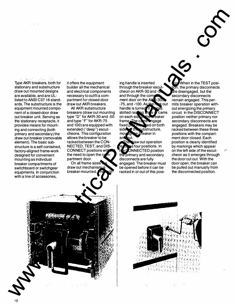
Type AKR breakers, both for stationary and substructure draw out mounted designs are available, and are ULIisted to ANSI C37. 1 6 standards. The substructure is the equipment mounted component of a closed-door draw out breaker unit. Serving as the stationary receptacle, it provides means for mounting and connecting (both primary and secondary) the draw out breaker (removable element). The basic substructure is a self-contained, factory-al igned frame-work designed for convenient mounting as individual breaker compartments of switchboard or switchgear equipments. In conjunction with a l ine of accessories,
10
it offers the equipment builder all the mechanical and electrical components necessary to outfit a compartment for closed-door draw out AKR breakers.
All AKR substructure breakers (draw out mounting type "D" for AKR-30 and -50 and type "F" for AKR-75 and 1 00) are equipped with extended ("deep") escutcheons. This configuration allows the breaker to be racked between the CONNECTED, TEST, and DISCON NECT positions without the need to open the compartment door.
On all frame sizes the draw out mechanism is breaker mounted. The rack-
ing handle is inserted through the breaker escutcheon on AKR-30 and -50, and through the compartment door on the AKR-30S, -75, and -1 00. As the rack out handle is turned, it rotates slotted racking arms or cams on each side of the breaker frame. The cams engage fixed pins mounted on both sides of the substructure, moving the breaker in and out.
The draw out operation features four positions. In the CONNECTED position the primary and secondary disconnects are fully engaged. The breaker must be opened before it can be racked in or out of this posi-
tion . When in the TEST position, the primary disconnects are disengaged, but the secondary disconnects remain engaged. This permits breaker operation without energizing the primary circuit. In the DISCON NECT position neither primary nor secondary disconnects are engaged. Breakers may be racked between these three positions with the compartment door closed. Each position is clearly identified by markings which appear on the left side of the escutcheon as it emerges through the door cut out. With the door open, the breaker can be pul led out manually from the disconnected position.
www . El
ectric
alPar
tMan
uals
. com
www . El
ectric
alPar
tMan
uals
. com
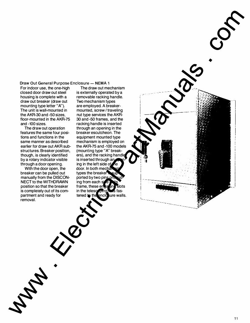
Draw Out General Purpose Enclosure- NEMA 1 For indoor use, the one-high closed door draw out steel housing is complete with a draw out breaker (draw out mounting type letter "/\'). The unit is wall-mounted in the AKR-30 and -50 sizes, floor-mounted in the AKR-75 and -100 sizes.
The draw out operation features the same four positions and functions in the same manner as described earlier tor draw out AKR substructures. Breaker position, though, is clearly identified by a rotary indicator visible through a door opening.
With the door open, the breaker can be pulled out manually from the DISCONNECT to the WITHDRAWN position so that the breaker is completely out of its compartment and ready for removal.
The draw out mechanism is externally operated by a removable racking handle. Two mechanism types are employed. A breakermounted, screw I traveling nut type services the AKR-30 and -50 frames, and the racking handle is inserted through an opening in the breaker escutcheon. The equipment mounted type mechanism is employed on the AKR-75 and -1 00 models (mounting type "/\' breakers), and the racking handle is inserted through an opening in the left side of the door. In both mechanism types the breaker is supported by two pins protruding from each side of its frame, these engaging slots in the telescoping rails fastened to the enclosure walls.
' II
1 1
www . El
ectric
alPar
tMan
uals
. com
www . El
ectric
alPar
tMan
uals
. com
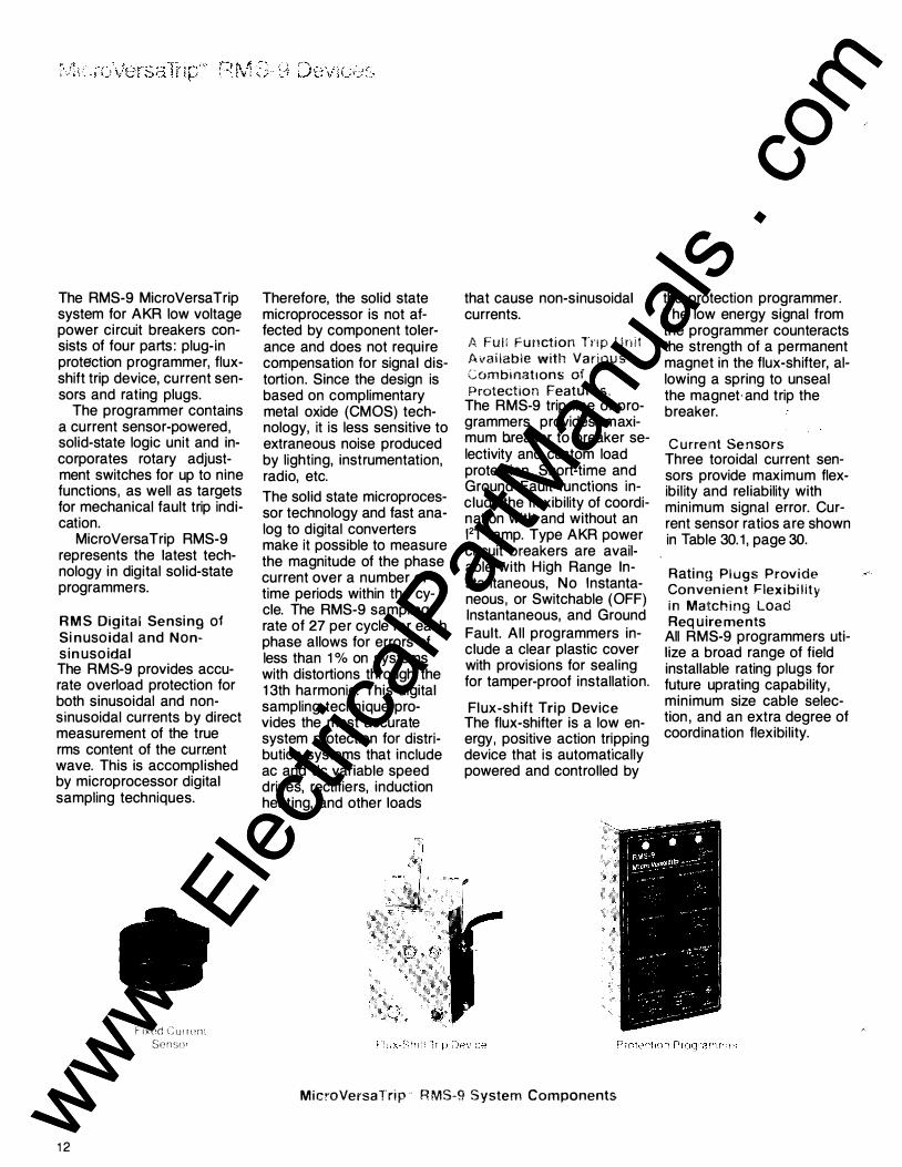
The RMS-9 MicroVersaTrip system for AKR low voltage power circuit breakers ?Onsists of four parts: plug-In protection programmer, fluxshift trip device, current sensors and rating plugs.
The programmer contains a current sensor-powered, solid-state logic unit and incorporates rotary adjus�ment switches for up to nme functions, as well as targets for mechanical fault trip indication.
MicroVersaTrip RMS-9 represents the latest technology in digital solid-state programmers.
RMS Digital Sensing of Sinusoidal and Nonsinusoidal The RMS-9 provides accurate overload protection for both sinusoidal and nonsinusoidal currents by direct measurement of the true rms content of the curr.ent wave. This is accomplished by microprocessor digital sampling techniques.
12
F IXOd <::urrL'rl\ Sensor
Therefore, the solid state microprocessor is not affected by component tolerance and does not require compensation for signal distortion. Since the design is based on complimentary metal oxide (CMOS) technology, it is less sensitive to extraneous noise produced by lighting, instrumentation, radio, etc.
The solid state microprocessor technology and fast analog to digital converters make it possible to measure the magnitude of the phase current over a number of time periods within the cycle. The RMS-9 sampling rate of 27 per cycle for each phase allows for errors of less than 1 % on systems with distortions through the 13th harmonic. This digital sampling technique provides the most accurate system protection fo� distribution systems that mclude ac and de variable speed drives, rectifiers, induction heating, and other loads
that cause non-sinusoidal currents.
A FuH Function lnp Unit Available with Vanous Gombmat1ons of Protection Features.
The RMS-9 trip l ine of programmers provides maximum breaker to breaker selectivity and custom load protection. Short-ti�e a�d Ground Fault functions Include the flexibility of coordination with and without an 12T ramp. Type AKR power circuit breakers are available with H igh Range Instantaneous, No Instantaneous, or Switchable (OFF) Instantaneous, and Ground Fault. All programmers include a clear plastic cover with provisions for sealing for tamper-proof installation.
Flux-shift Trip Device The flux-shifter is a low energy, positive action tr�pping device that is automatically powered and controlled by
MicroVersaTrip · RMS-9 System Components
the protection programmer. The low energy signal from the programmer counteracts the strength of a permanent magnet in the flux-shifter, allowing a spring to unseal the magnet·and trip the breaker.
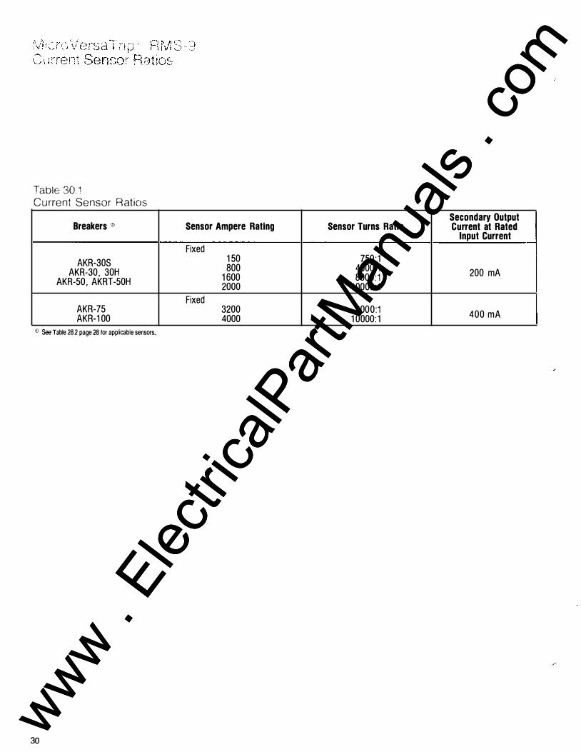
Current Sensors Three toroidal current sensors provide maximum flexibil ity and reliability with minimum signal error. Current sensor ratios are shown in Table 30. 1 , page 30.
Ratin�� Plugs Provide Convenient Flexibility in Ma!tching Load Req uirements
All RMS-9 programmers utilize a broad range of field installable rating plugs for future uprating capability, minimum size cable selection , and an extra degree of coordination flexibi lity.
www . El
ectric
alPar
tMan
uals
. com
www . El
ectric
alPar
tMan
uals
. com

N
0A
08
0C
Power Supply Board Programmer Faceplate
XFMR
INST
GROUND
FAULT .------.
SIGNAL AID
SWITCHES
COMPARATOR
IOC TRIP
SWITCH MicroVersaTnp" RMS-9 blocK diagram.
ILP
GF
LT TRIP
ST
TO
FLUX
SHIFTER
Logic Board
Ep1c MicroVersaTrip'" Board (when used)
13
www . El
ectric
alPar
tMan
uals
. com
www . El
ectric
alPar
tMan
uals
. com
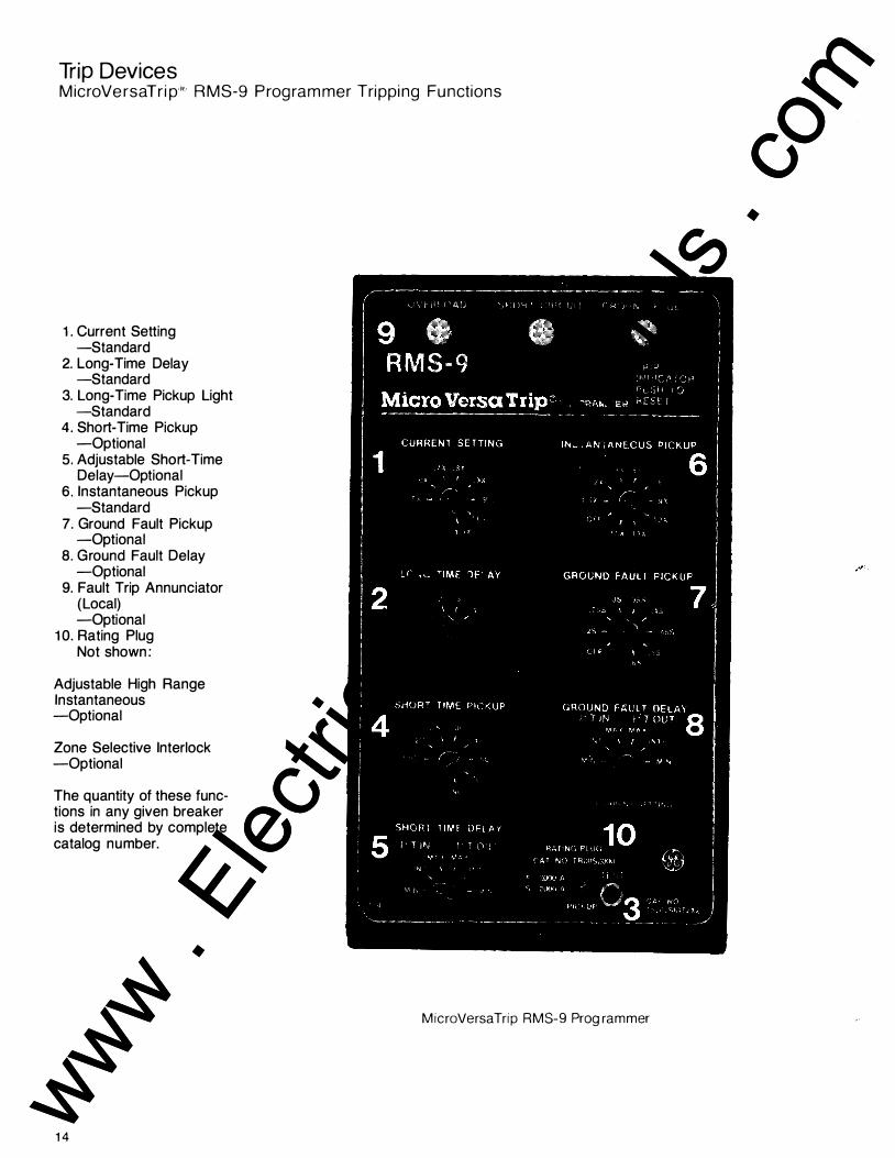
Trip Devices Micro Versa Trip R RMS-9 Programmer Tripping Functions
1 . Current Setting -Standard
2. Long-Time Delay -Standard
3. Long-Time Pickup Light -Standard
4. Short-Time Pickup -Optional
5. Adjustable Short-Time Delay-Optional
6. Instantaneous Pickup -Standard
7. Ground Fault Pickup -Optional
8. Ground Fault Delay -Optional
9. Fault Trip Annunciator (Local) -Optional
1 0. Rating Plug Not shown:
Adjustable High Range Instantaneous -Optional
Zone Selective Interlock -Optional
The quantity of these functions in any given breaker is determined by complete catalog number.
14
MicroVersaTrip RMS-9 Programmer
www . El
ectric
alPar
tMan
uals
. com
www . El
ectric
alPar
tMan
uals
. com

Table 15.1 MicroVersaTrip® RMS-9 Programmer Function Settings
Current Long-time Short-time
Frame Max. Sensor Setting Pick Up (Multiple
Size Amp Rating (Amps) (Multiple of of Current Rating (S) Rating Plug Amps) Setting)
(X) (C)
AKR-30S 800 150, 400, 800
.5, .6, .7, .8, Fixed at 1.0 of AKR-30H .9, .95, 1.0, 1.1 Current Setting
AKR-50 1600 800, 1600 .5, .6, .7, .8, Fixed at 1.0 of .9, .95, 1.0, 1.1 Current Setting
AKRT-50 2000 2000 .5, .6, .7, .8, Fixed at 1 .0 of .9, .95, 1.0, 1.1 Current Setting
.5, .6, .7, .8, Fixed at 1.0 of AKR-75 3200 3200
.9, .95, 1.0, 1.1 Current Setting
AKR-100 4000 4000 .5, .6, .7, .8, Fixed at 1.0 of .9, .95, 1.0, 1.1 Current Setting
Adjustable Adjustable High Range Instantaneous Instantaneous Instantaneous
Frame Pick Up without ST Pick Up with ST (Multiple of Frame Size (Multiple of Rating (Multiple of Rating Short-Time®
Plug Amps) Plug Amps) Rating) {X) (X) (H)
AKR-30S 1.5, 2, 3, 1.5, 2, 3, 5, 7, .4, .6, AKR-30H 5, 7, 9, 10 9, 10, 13, 15 .8, 1.0
1.5, 2, 3, 1.5, 2, 3, 5, 7, .4, .6, AKR-50
5, 7, 9, 10 9, 10, 13, 15 .8, 1.0
1.5, 2, 3, 1.5, 2, 3, 5, 7, .4, .6, AKRT-50
5, 7, 9, 10 9, 10, 13, 15 .8, 1.0
AKR-75 1.5, 2, 3, 1.5, 2, 3, 5, 7, .4, .6, 5, 7, 9, 10 9, 10, 13 .8, 1.0
1.5, 2, 3, .4, .6, AKR-100 1.5, 2, 3, 5, 7, 9
5, 7, 9 .8, 1.0
<D Time delay shown at 600% of current setting at lower limit of band.
® Time delay shown at lower limit of each band. All pickup tolerances are± 10%.
® Refer to Buylog catalog Table 1, page 6-3 for frame short-time ratings.
@ For AKR-30S only.
Pick Up (Multiple Delay<D of current Delay
(Seconds) Setting) (Seconds) (C)
2.4, 4.9, 9.8, 20
2.4, 4.9, i"T in.<D 9.8, 20 1.5, 2.0, 2.5, .40 2.4, 4.9, 3.0, 4,.0, 5.0, 9 .8, 20 7.0, 9.0 I"T out®
2.4, 4.9, .10, .21, .35
9.8, 20
2.4, 4.9, 9.8, 20
Triple Selective Trip, Pickup
Fixed High (Multiple of Range Sensor amp
Instantaneous Rating) @® (S)
+0 .2, .25, .3, 22kA .35, .4, .45,
-20% .5, .6
.2, .25, .3, NA .35, .4, .45,
.5, .6
.2, .25, .3, NA .35, .4, .45,
.5, .6
.2, .22, .24, NA .26, .28, .30,
.34, .37
.2, .22, NA .24, .26,
.28, .3
® Tnple select1ve tnp 1s standard when long-time/short-time only is required.
® Time delay shown at lower limit of each band. Ground fault pick up
Ground Fault
Delay Delay® with I"T without 12
(Seconds) (Seconds)
.10, .21, .35
.40 .10, .21, .35 at 200%
of pick up at lower .10, .21, .35
limit of band
.10, .21, .35
.10, .21, .35
not to exceed 1200 amps. X = Rating plug amps S = Sensor amp rating C = Current setting H = Short-time rating
Table 15.2 MicroVersaTrip® RMS-9 Programmer-Available Combinations (Add Suffix to Basic Catalog Number)
Programmer Long- Short-Suffix time time
(L) (S)
Adjustable Instantaneous
L1 X LIT1 X LIGT2 X LIGT2Z1 X LSIT1 X X LSIGT2 X X LSIGT2Z1 X X LSIGT2Z2 X X
Adjustable High Instantaneous
LSHT1 X X LSHGT2 X X LSHGT2Z1 X X LSHGT2Z2 X X
Fixed High Instantaneous®
LSKT1 X X LSKGT2 X X LSKGT2Z1 X X LSKGT2Z2 X X
No Instantaneous(!)
LST1 X X LSGT2 X X LSGT2Z1 X X LSGT2Z2 X X
Switchable Instantaneous/Ground Fault<D@
LSIGT2X X
<D Not available for AK0-70-30S or AKRU-70-30S.
® Only available for AKR-70-30S or AKRU-70-30S.
X
Adj. Fixed Adj. High High In st. In st. In st.
{I) (H) (K)
X X X X X X X X
X X X X
X X X X
X
® Requires zone selective interlock module types TIM1 (120V ac control voltage) or TIM2 (125V de control voltage).
GF® GF/ST® Ground OLISC OLISC/GF Zone Zone Switch
Fault Targets Targets Interlock Interlock lnst/GF (G) {T1) (T2) (Z1) (Z2) (X)
X X X X X X
X X X
X X X X X
X X X X X X X X X
X X X X X X X X X
X X X X X X X X X
X X X
@ Not UL Listed.
1 5
www . El
ectric
alPar
tMan
uals
. com
www . El
ectric
alPar
tMan
uals
. com

Trip Devices MicroVersaTnp" RMS-9 Tripping Functions
Long-Time Functio n Moving from left to right on the current axis, Figure 16.1, the upper part of the time current curve is the longtime pickup. This is the function used to protect a circuit against low magnitude overcurrents. The breaker trips because the current has exceeded the long-time setting. If a breaker is protecting a motor, the start-up surge (in-rush current) can be accommodated by setting the breaker to allow for a momentary delay while the motor has a chance to reach its normal operating speed or ful l load current.
Short-Time Function The middle portion of the curve is the short-time function. It is used to protect against higher magnitude overcurrents and low-level short circuit faults. Overcurrent due to short circuits is generally in the order of 10 or more times ful l-load current, and is measured as symmetrical RMS (root mean square) short-circuit current.
Instantaneous Function At the bottom of the time current curve is the protective device's instantaneous function. The instantaneous trip point determines the level at which the breaker will trip without an intentional time delay. This immediate interruption occurs only as a result of a severe overcurrent condition, such as a high-level short circuit, that would damage the electrical system if not interrupted. An instantaneous trip can be adjustable, depending upon the application.
16
_, "" 10 a .. a " a .. a " a
.. a
" a
" a
" 0 9 ' ' 0 7 0
a a
0
0
0
0 9 ' 7 ' '
.
7
1
9 ' ' ' '
.
'
'
• 7 .111
CURRENT SETTING
1 1X
LONG-TIME
PICKUP long Ttme /
'-'\ lnt
.�.�.�,� •• �.--���,�.�.�.�,� • • � .. --�,�a�lO� .. MULTIPLES OF CURRENT SETTING (C)
LONG-TIME
DELAY
� �, -
r-: 0 = 0 -
�� � �
// /. V/ /. /. // / � //; / � � %
'
'I 1/1
�+ AOJUSTAaLt
� /V �t;; VY::
{0 <
Appltrdl•<'ln Det .. ,,.,,ne�
End 01 Cu'v�
v /V: /� V/; « � �
INSTANTANEOUS
PICKUP 3X SX
1.5X & 9X �®f OFF 10X 15X 13X
flltE.D
h. � �·· 02
'/ C2
V/ v � "'
7 . 5 & 11910 " " MULTIPLES OF INSTANTANEOUS PICKUP
www . El
ectric
alPar
tMan
uals
. com
www . El
ectric
alPar
tMan
uals
. com
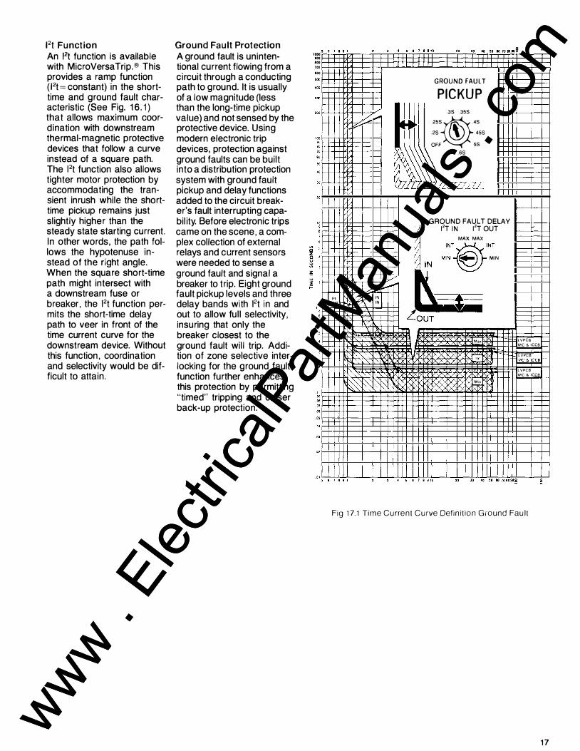
Ft Function An Ft function is available with MicroVersaTrip.® This provides a ramp function Wt =constant) in the shorttime and ground fault characteristic (See Fig. 1 6 .1) that allows maximum coordination with downstream thermal-magnetic protective devices that follow a curve instead of a square path. The 12t function also allows tighter motor protection by accommodating the transient inrush while the shorttime pickup remains just sl ightly higher than the steady state starting current. In other words, the path follows the hypotenuse instead of the right angle. When the square short-time path might intersect with a downstream fuse or breaker, the l2t function permits the short-time delay path to veer in front of the time current curve for the downstream device. Without this function, coordination and selectivity would be difficult to attain.
Ground Fault Protection A ground fault is unintentional current flowing from a circuit through a conducting path to ground. It is usually of a low magnitude (less than the long-time pickup value) and not sensed by the protective device. Using modern electronic trip devices, protection against ground faults can be built into a distribution protection system with ground fault pickup and delay functions added to the circuit breaker's fault interrupting capabil ity. Before electronic trips came on the scene, a complex collection of external relays and current sensors were needed to sense a ground fault and signal a breaker to trip. Eight ground fault pickup levels and three delay bands with l2t in and out to allow ful l selectivity, insuring that only the breaker closest to the ground fault will trip. Addition of zone selective interlocking for the ground fault function further enhances this protection by permitting "timed" tripping and closer back-up protection.
1000 '" '" "'
g � ��·�··�··����·�·t·�·�· ·g·�,��'§'�"I!"�"g'g"�"�'"!-���
"' f-+-++-I'H---+---t---1 '"R!E GROUND FAULT PICKUP
35 .355 255�.45
25 � 455
OFF 55 .65
GROUND FAULT DELAY �iE [/ MAX MAX
I' I OlfT
II� 12T IN 12T OUT l: I INT � INT
f\ �� t ·.: "' rdt' :� I :§EJg�gg§ LouT
'1-+++W----t"�d-t--H-Ma� LVPCB 1--
MC & ICCB ,......_ LVPCB
��--LVPCB MC & !CCB
Moo 1}
Fig 17.1 Time Current Curve Definition Ground Fault
17
www . El
ectric
alPar
tMan
uals
. com
www . El
ectric
alPar
tMan
uals
. com

Type AKR Breakers Trip Devices MicroVersaTrip R RMS-9 Tripping Functions
Current Setting (Standard) The adjustable current setting determines the nominal long time current setting with a ± 1 0% band width . With a 1 . 1 setting the breaker will carry indefinitely without tripping the rating plug rating . Changing the setting changes the norminal current rating for the breaker.
Long-Time Delay (Standard) This long-time delay adjustment varies the time it will take the breaker to trip under sustained overload conditions. It provides the function of withstanding momentary overloads such as motor starting, welding, or other overcurrent conditions without interrupting the service.
Long-Time Pickup Light (Standard) The long-time pickup light provides visual indication that the breaker is experi-encing an overload condi-tion. Indication is provided by a light-emitting diode (LED) which is only activated prior to trip-out and during long-time time-out. Saves test and system start up time.
Short-Time Pickup (Optional) This short-time picKup adjustment controls the level of high current the breaker can carry for short periods of time without tripping. Per-mits downstream breakers to clear short circuit faults without tripping out the upstream protective device.
18
CURRENT SETTING
1.1X
SETTING( C)
LONG TIME DELAY
2 3
,�.
DELAY
RATING PLUG
CAT. NO. TR20S2000
x�2ooo A • TEST
S�2000A 0 PICKUP
PICKUP
SHORT TIME PICKUP
2.5C 3C
2C®C
1.5C � SC
7C
9C
SHORT-TIME PICKUP
www . El
ectric
alPar
tMan
uals
. com
www . El
ectric
alPar
tMan
uals
. com

Short-Time Delay (Optional) The short-time delay adjustment is used in conjunction with the short-time pickup setting to provide a further refinement of coordination between circuit breakers. It establishes the time interval the breaker will wait before responding to the shortcircuit current level selected on the short-time trip point adjustment.
Adjustable Instantaneous Pickup (Standard)
The instantaneous trip point determines the level at which the breaker will trip without intentional time delay (0.025 seconds or less). This immediate interruption occurs only as a result of a severe overcurrent condition, thereby minimizing damage to the electrical system and equipment.
SHORT TIME DELAY
12T IN 12T OUT
MAX MAX
.::'®':. DELAY
INSTANTANEOUS PICKUP
3X SX 2X@7X
1.5X & 9X
OFF 10X 15X 13X
INSTANTANEOUS PICKUP
1 9
www . El
ectric
alPar
tMan
uals
. com
www . El
ectric
alPar
tMan
uals
. com

Trip Devices Continued
High Range Instantaneous
Ground Fault Pickup and Ground Fault Delay (Optional) The ground fault pickup adjustment controls the level of ground fault current at which circuit interruption will occur. To comply with the 1 981 National Electrical Code (NEC 230-95), no trip point exceeds 1 200 amperes. The common square knee of the curve can be replaced with an l2t function to facil itate coordination with downstream devices such as thermalmagnetic breakers and fuses whose time-current curves do not easily relate to the square-shape sensing characteristics common to solid state trip devices.
Memory Circuit Because of the highly intermittent and erratic nature of arcing ground faults, a memory circuit has been incorporated in all MicroVersaTrip ground fault sensing circuits as standard. The memory circuit integrates arcing fault current with time, essentially summing the intermittent ground current spikes. In the
20
Includes adjustable shorttime pickup, adjustable short-time delay and a highlevel instantaneous setting is adjustable in four steps from 40 to 1 00 percent of the circuit breaker frame
The ground fault delay adjustment is used to add a pre-determined delay in time to the trip point once the ground fault pickup level has been reached. This provides tripping selectivity between main and feeder or other downstream breakers. The ground fault unit also includes as standard an inverse 12t ramp to substantially improve coordination with downstream protective devices such as fuses and thermal magnetic circuit breakers.
diagrams, it can be seen how the memory function works. Diagram A shows a typical ground fault with half-cycles, whole cycles and multiple cycles missing, as normally occurs. Diagram B shows trip response of a typical ground fault function which does not include memory. The
short-time rating permitting maximum use of the breaker's short-time capability. This high level instantaneous function increases system protection without losing selectivity.
GROUND FAULT PICKUP
.35 .355
.
. 255®.45 25 � .455
OFF .55 .65
GROUND FAULT PICKUP
GROUND FAULT DELAY
12T IN 12T OUT
MAX MAX
"'�-@"�, GROUND FAULT
DELAY
breaker never trips because
*
the time delay circuits are @-f-1rr-''-+:11--l--L....li....J..L-'----reset with every missing cycle. Diagram C shows response @ of Micro Versa Trip ground
B +-......_.. _ _._____.L_.LL.-1-L.L--.
fault circuits to the same ground fault; the circuit's memory carries through the © missing cycles and gener- -¥----G-coc-nd_F_ac-11 R-e-spo-ns-e--+-ates a trip Signal after the
With Memocy
preset time delay.
www . El
ectric
alPar
tMan
uals
. com
www . El
ectric
alPar
tMan
uals
. com

Fault Trip Indicators Indicators are designed to reduce system downtime by analyzing any overcurrent fault and identifying its cause. Mechanical pop-out type indicators are available on the programmer for identifying overload or short circuit overcurrent faults when breakers are ordered without integral ground fault protection . Indicators are available to identify overload, short circuit and ground fault trips - for breakers supplied with integral ground fault protection.
Zone Selective Interlocking The standard means of obtaining selectivity between main and feeder breakers is by incorporating programmers with timecoordinated trip characteristics. This consists of setting the farthest downstream breaker with a small time delay, and progressively increasing the time delay as you get closer to the main protective device. The disadvantage in this method is that the system must now endure the stress of the high current fault until time-out occurs.
The Zone Selective Interlock module, Figure 21. 1 , receives a signal from a downstream MicroVersaTrip programmer (Logic 0) which causes the module to transmit a low-level interlock signal to a MicroVersaTrip programmer upstream. The interlock signal activates the LED portion of an LED-
OVERLOAD
©
Transistor Opto-isolator in the upstream programmer causing the fixed delay band to shift from "MIN" to the programmer delay band setting Figure 1 4 . 1 . Both the Short-Time and Ground Fault functions are capable of being interlocked.
Zone Selective Interlocking is available for the shorttime function and the ground fault function, or for the ground fault function only.
SHORT CIRCUIT GROUND FAULT
© © TRIP
INDICATOR
PUSH TO RESET
Fig. 21.1 Multi-Zone Interlocking
21
www . El
ectric
alPar
tMan
uals
. com
www . El
ectric
alPar
tMan
uals
. com

Trip Devices EC Trip Devices DC Applications
General Type EC overcurrent trip devices are magnetically operated, using a series coil (or single conductor and an associated magnetic structure) to provide tripping force. Three basic characteristics: long-time delay, shorttime delay and instantaneous, can be used in various combinations to suit the application.
Type EC-2A
Long-Time Delayis accomplished with a positive-displacement oil piston. Sealing of the assembly el iminates variations caused by atmospheric contamination, and silicone oil minimizes variations in time delay due to changes in ambient temperature.
Short-Time Delay is accomplished with a rugged mechanical escapement.
lnstantaneoustripping is obtained when a tension spring yields to the force exerted on the magnetic armature at short circuit current levels, permitting the armature to move independently of the time delay piston.
AKR breakers with EC trips are for use on DC system voltages, and are available in ratings of 40-6000 amperes. One EC trip device
Type EC-1
is mounted in each breaker pole and contains functional adjustments, overcurrent detection and tripping hardware.
EC trip devices are available as type EC-2A (standard for frames through 2000A), EC-1 (optional for frames through 2000A) and EC-18 (standard for 4000 and 6000A frames). Trip characteristics are described in the table below.
Type EC-18 Trip Device for 600-2000 amp frame breakers. Available in combinations of long-time and instantaneous elements, or instantaneous alone.
Trip Device for 600-2000 amp frame breakers. Combines long-time and short-time elements for intentional delay up to the short-time rating of the breaker. Instantaneous may be added.
Trip Device for 4000 and 6000 amp frame breakers. Combines long-time and short-time elements for intentional delay up to the shorttime rating of the breaker. Instantaneous may be added.
Table 22.1 Adjustment Ranges for EC Trip Devices
Trip Long-Time Short-Time Instantaneous Device Pickup <D Delay® Pickup Delay® Pickup
(1A) MAX- adj 15-38 sec or 4-9X
EC-2A 80-160%X (1B) INTER- adj 7.5-18 sec - - 6-12X (±10%) or 9-15X or
(1C) MIN -adj 33-82 sec 80-250% X ® (1A) MAX- 30sec (2A) MAX - 23 sec
or 2-5X or High Set EC-1 80-160%X (1B) INTER -15 sec 3-7X or (2B) INTER -15 sec up to 15X
(±10%) or 4-10X or Non-Adjustable (1C) MIN- 5 sec (2C) MIN -07 sec
(2AA) MAX -20 sec (188) MAX-45 sec 2-5X or 4-9X
EC-18 80-160%X or 3-7Xor (288) INTER- 13 sec 6-12X (±15%) (1CC) MIN- 2 sec 4-10X or 9-15X or
(2CC) MIN - 07 sec 80-250% X ®
<D X = Trip device ampere rating. If trip devices are set above 100% for coordination purposes, such settings do not increase the breaker's continuous current rating.
® At lower limit of band at 6 times pickup setting.
® At lower limit of band at 2V2 times pickup setting.
® Low-set instantaneous. Not available in combination with long time delay.
22 www . El
ectric
alPar
tMan
uals
. com
www . El
ectric
alPar
tMan
uals
. com
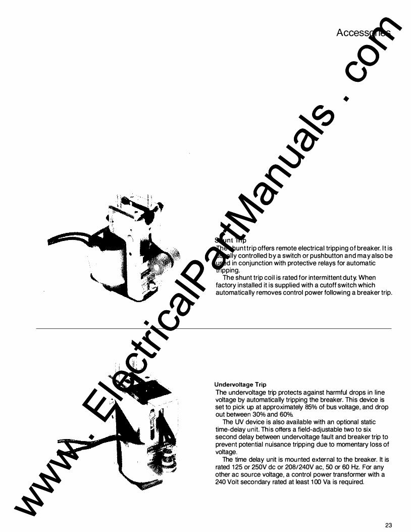
Accessories
Shunt Trip The shunt tr ip offers remote electrical tripping of breaker. It is usually controlled by a switch or pushbutton and may also be used in conjunction with protective relays for automatic tripping.
The shunt trip coil is rated for intermittent duty. When factory installed it is supplied with a cutoff switch which automatically removes control power following a breaker trip.
Undervoltage Trip The undervoltage trip protects against harmful drops in l ine voltage by automatically tripping the breaker. This device is set to pick up at approximately 85% of bus voltage, and drop out between 30% and 60%.
The UV device is also available with an optional static time-delay unit. This offers a field-adjustable two to six second delay between undervoltage fault and breaker trip to prevent potential nuisance tripping due to momentary loss of voltage.
The time delay unit is mounted external to the breaker. It is rated 125 or 250V de or 208/240V ac, 50 or 60 Hz. For any other ac source voltage, a control power transformer with a 240 Volt secondary rated at least 1 00 Va is required.
23
www . El
ectric
alPar
tMan
uals
. com
www . El
ectric
alPar
tMan
uals
. com

Accessories Continued
Auxiliary Switch The auxi l iary switch is used for remote indication of breaker main contact position. It is available in groupings of tour contacts (two stages) or ten contacts (five stages). Each stage is composed of one "a" Type (N .O.) contact and one "b" Type (N.C.) contact. All contacts feature rugged doublebreak construction.
Electric Lock Out Device The electric lock out device provides a means of electrically interlocking breakers so that two cannot be closed at the same time. This electromechanical device consists of a coil whose winding must be energized to close the breaker. Once the breaker is closed, loss of voltage will not trip the breaker. A bypass interlock is provided tor in itial startup. Refer to the UV device tor ratings and coil characteristics. Auxiliary switches for cross-interlocking breakers must be ordered separately.
Bell Alarm Switch The bell alarm operates one "a" and one "b" contact, two "a's", or two "b's". It is activated when the breaker is tripped by any means (automatic) other than the manual trip button or the shunt trip device. The contacts may be used for remote indication of an automatic trip. The lock out feature is available to mechanically lock the breaker "Open" when the device is activated. "Reset" is accomplished through operation of the manual trip button or shunt trip device. The bell alarm is avai lable without the lock out feature when so specified.
24
Key Interlock Provision Prevents operation of a remote function un less the breaker has been tripped. Provision is made to accept a lock assembly furnished by purchaser (Kirk or Superior.)
www . El
ectric
alPar
tMan
uals
. com
www . El
ectric
alPar
tMan
uals
. com

Close Button The AKA electrically operated breaker is furnished as standard without operating handle and is closed by receipt of a signal provided by the remote momentary closure of a contact of a relay or switch. A close button escutcheon, mounted, momentary contact is available when specified.
Open Fuse Lock Out Device
Fuse Roll Out The AKR-75 and -1 00 draw out AKRU breakers require a separate fuse roll out. All fuse roll outs accept Class L fuses 800-4000A. The draw out breaker elements used in conjunction with these fuse roll out elements should be equipped with an open fuse lock out device. The breaker component should have provisions for key interlock.
The open fuse lock out device automatically trips the breaker if one of the fuses opens. The breaker is locked open until the reset button of the phase involved is reset.
Remote Close Solenoid (For manually-operated AKR-30H, -50, AKRT-50H b reakers) The solenoid provides a means to electrically close the above breakers from a remote location. It may be controlled by a switch or pushbutton for five-cycle closing. Breaker must be charged locally. Avai lable ratings: See Table 39.2, page 39- not available on AKR-308.
Maintenance Clc-sing Handle The maintenance closing handle is furnished as standard (one handle for up to five breakers.) The maintenance handle is provided for the slow closing motion required during contact adjustment procedures (not required on manually operated AKR-75 and 100 breakers.)
Reverse Current Device The reverse current device is available for de breakers only. It is designed to trip the breaker if current reverses direction.
Operations Counter This accessory mounts on the breaker as a five digit, non-resettable counter actuated by the breaker cam shaft.
25
www . El
ectric
alPar
tMan
uals
. com
www . El
ectric
alPar
tMan
uals
. com

Accessories OEM Substructure
Secondary Disconnects Breakers may be ordered with up to twenty-one draw out control disconnect points furnished in groups of seven. Seven circuit disconnect block kits and mounting brackets for up to three blocks are available for mounting in the substructure.
Keylock Provision Keylock accessory kit provides mechanism interlock assembly for mounting a single or double multiple lock.
26
Fourth Wire Disconnect Fourth wire disconnect kits for use when three phase, four wire ground fault protection is required provides for connection to fourth wire neutral sensor.
Position Switch The position switch is activated by the AKR breaker when the breaker is in its connected position and then contacts of the switch change state when moved to the test position. www .
Elec
tricalP
artM
anua
ls . c
om
www . El
ectric
alPar
tMan
uals
. com

Current Transformer Mounting Hardware Provides the necessary mounting hardware for mounting applicable current transformers in the substructure.
Programmer Secondary Disconnect Required when programmer on breaker has zone selective interlocking .
Door I nterlock Kit Provides for interlocking door (hinges left or right) such that breaker must be in the disconnect position before door can be opened. Interlock is defeatable for authorized access.
200UA "T" Connector (For 1600A and 2000A substructures.) Provides alternate means for bus connecting to the substructure.
Shutter Kit Shutters to cover primary disconnects when breaker is moved to the test position.
Provisions for Padlocking Breaker in Disconnect Positio n Padlock assembly engages with the breaker mounting bracket in the substructure. It prevents the breaker from being moved from the disconnected to the test or connected positions. The padlock slot will accept three , 3fa inch diameter hasps.
27
www . El
ectric
alPar
tMan
uals
. com
www . El
ectric
alPar
tMan
uals
. com

Ratings
Basic Ratings AKA L VPCB with MicroVersa Trip® RMS-9 programmer is rated for shorttime withstand current and interrupting capacity (rms symmetrical) . The maximum short-time rating is shown for 30 cycle duration at 50/60 Hz.
For de applications, electromechanical EC type trip devices are available for de ratings up to 250Vdc.
Table 28 1 Summary of Breaker Ratings
Rated Frame Short Circuit Ratings
Voltage Size RMS Symmetrical
Breaker T ype kA Short-
With Without (Nominal) (Amperes) lnstanta- lnstanta-
60Hz T ime neous Trip neousTrip
AK-25 600 22 22 22 AKR-30S 800 22 22 22 ® AKR-30 800 30 30 30
AKR-30H 42 42 42 600 AKSIAKR-50 1600 42 42 42
AKSI AKR-50H 65 65 65 AKST I AKRT -SOH 2000 65 65 65
AKR-75 3200 65 65 65 AKR-100 4000 85 85 85
AK-25 600 22 30 22 AKR-30S 800 22 30 30® AKR-30 800 30 30 30
AKR-30H 42 42 42 480 AKSIAKR-50 1600 50 50 50
AKSI AKR-50H 65 65 65 AKST I AKRT -SOH 2000 65 65 65
AKR-75 3200 65 65 65 AKR-100 4000 85 85 85
AK-25 600 22 42 22 AKR-30S 800 22 42 42 ® AKR-30 800 30 42 30
AKR-30H 42 50 42 240 AKSIAKR-50 1600 50 65 50
AKSIAKR-50H 65 65 65 AKST I AKRT -SOH 2000 65 65 65
AKR-75 3200 65 85 65 AKR-100 4000 85 130 85
CD T he maxtmum fuse ratmg ts the largest fuse whtch tests show wtll result tn proper performance of the breaker and fuse in combination under short circuit conditions. Only Gould fuses should be used for proper coordination.
® Fuses are mounted on separate fuse roll-out element. ® Refer to time-current curves GES-6000 (for EC-1) and GES-6005 (for EC-1 B). ®Observe Table 5 minimum overcurrent trip ratings.
® Only dual ratio sensors are available on AKR-30S when programmers are furnished with HighRange Instantaneous or Triple Selective Trip.
® Triple Selective Trip at 1 X short-time rating when standard Instantaneous Trip is omitted.
28
Table 282 - Overcurrent Trip Device Current Ratings 1n Amperes
Breaker MicroVersaTrip®RMS-9 50/60 Hz ac
Frame Sensor Rating Rating Plug Amps (s) Amps (x)·
Tappe d Fixed Plug
AK-25 70, 100, 150, 225 Rating Equals 200, 300, 400, 600 Sensor Tap
150 60, BO, 100, 125, 150
AKR-30S, 400 150, 200, 225, 250, AKR-30 300, 400 AKR-30H BOO 300, 400, 500, 600,
700, BOO BOO 300, 400, 500, 600,
AKR-50 700, BOO AKR-50H 1600 600, BOO, 1000,
1200, 1600
AKRT-50H 2000 BOO, 1000, 1200, 1500, 1600, 2000
AKR-75 3200 1200, 1000, 2400,
3200
AKR-100 4000 1500' 2000' 2500'
3000, 4000
x �Rating plug amps s �Sensor amp rating
EC Device Rating de·"'
40, 50, 70, 90, 100, 125, 150, 175, 200, 225, 250, 300, 350.
400' 500' 600
NOT AVAILABLE ON AKR-30S
100,125,150,175,200, 225, 250, 300, 350, 400, 500, 600, BOO
200, 225, 250, 300, 350, 400, 500, 600,
BOO, 1000, 1200, 1600, 2000
-
2000' 2500' 3000' 4000
2000, 2500, 3000, 4000, 5000, 6000
Table 28.3 Fused Breaker Ratings- Maximum 600V ac 50160 Hz
Table 28.5 Minimum EC Trip Ratings- Amperes at 250V de
Inter-rupting
Fuse Rating Frame Rating RMS
Breaker Size Amperes Sym-Type Amperes (j) met-
rica I Min. Max. kA
AKU-25 600 300 1200 200 AKRU-30S BOO 300 1600 200
AKRU-30 BOO 300 1600 200
AKRU-50 1600 450 2500 200 AKRU-75® 3200 2000 3000 200
AKR-100® 4000 2000 4000 200
Table 28.4 250V de Current Ratingswith EC Trip Device Only
Breaker Frame Short Size Circuit
Type Amperes kA AK-25 600 25
AKR-30 BOO 25 AKR-50 2000 50 AKR-75 4000 75
AKR-100 6000 100
With With Short-Time Trip
Breaker In stan· Characteristic ® Type neous
Trip 2C 2B 2A AK-25 40 175 200 250
AKR-30 100 175 200 250 AKR-50 200 350 400 500
2CC 2BB 2AA AKR-75
AKR-100 2000 2000 2000 2000
www . El
ectric
alPar
tMan
uals
. com
www . El
ectric
alPar
tMan
uals
. com
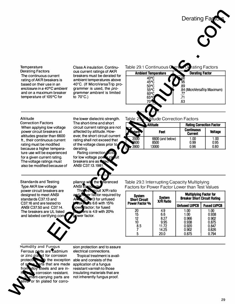
Tem perature Derating Factors The continuous current rating of AKR breakers is based on their use in an enclosure in a 40°C ambient and on a maximum breaker temperature of 105°C for
Altitude Correction Factors When applying low voltage power circuit breakers at altitudes greater than 6600 ft. , their continuous current rating must be modified because a higher temperature use will be experienced for a given current rating. The voltage ratings must also be modified because of
Standards and Testing Type AKR low voltage power circuit breakers are designed to meet ANSI standards C37.13 and C37.16 and are tested to ANSI C37.50 and C37. 14. The breakers are UL l isted and labeled certifying com-
Humid ity and Fungus
Ferrous parts are cadmium or zinc plated for corrosion protection with the exception of some parts that are made from alloy steels and are inherently corrosion resistant.
Current-carrying parts are silver or tin plated for corro-
Class A insulation. Continuous current ratings of AKR breakers must be derated for ambient temperatures above 40°C. ( If MicroVersaTrip programmer is used, the programmer ambient is l imited to 70°C.)
the lower dielectric strength. The short-time and short circuit current ratings are not affected by altitude. However, the short circuit current rating shall not exceed that of the voltage class prior to derating.
Rating correction factor for low voltage power circuit breakers are as listed in ANSI C37.13. 1981 .
pliance with the referenced ANSI standards.
The test circuit X/R ratio and power factor required by ANSI C37.13 for unfused breakers is 6.6 with 15% power factor; for fused breakers is 4.9 with 20% power factor.
sion protection and to assure electrical connections.
Tropical treatment is available and consists of the application of a fungus resistant varnish to those insulating materials that are not inherently fungus proof.
Derating Factors
Table 29.1 Continuous Current Derating Factors
Ambient Temperature Derating Factor
40°C 1 .00 45°C .95 50°C .89 55°C .84 (MicroVersaTrip Maximum) 60°C .77 65°C .71 70°C .63
Table 29.2 Altitude Correction Factors
Altitude Rating Correction Factor
Meters Feet Continuous
Voltage Current
2000 6600 (and below) 1 .00 1 .00 2600 8500 0.99 0.95 3900 13000 0.96 0.80
Table 29.3 I nterrupting Capacity Multiplying Factors for Power Factor Lower than Test Values
System System Multiplying Factor lor
Short Circuit XIR Ratio Breaker Short Circuit Rating
Power Factor Dfo Unfused LVPCB Fused LVPCB
20 4.9 1 .00 1 .00 15 6.6 1 .00 0.938 12 8.27 0.966 0.902 10 9.95 0.938 0.875
8.5 1 1 .72 0.920 0.847 7 14.25 0.902 0.826 5 20.0 0.875 0.794
29
www . El
ectric
alPar
tMan
uals
. com
www . El
ectric
alPar
tMan
uals
. com
.. J
Table 30. 1 C u rrent Sensor R atios
Breakers <D Sensor Ampere Rating Sensor Turns Ratio Secondary Output Current at Rated
Input Current
Fixed AKR-30S 1 50 750 : 1
AKR-30 , 30H 800 4000 : 1 200 mA 1 600 8000 : 1 AKR-50 , AKRT-50H 2000 1 0000 : 1
Fixed AKR-75 3200 8000:1 400 mA AKR-1 00 4000 1 0000: 1
CD See Table 28.2 page 28 for applicable sensors.,
30
www . El
ectric
alPar
tMan
uals
. com
www . El
ectric
alPar
tMan
uals
. com
l l
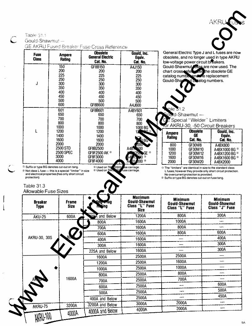
·lable 3 1 . : Gould- Shawm u t --"' E KR ' . r- 3 t..:J - A u r- used !: reaKer � - use c ross Reference
Fuse Ampere Obsolete Gould, Inc.
Class Rating General Electric Equiv.
cat. No. Cat. No. 150 GF8B150 A4J150 200 200 200 225 225 225 250 250 250
J 300 300 300 350 350 350 400 400 400 450 450 450 500 500 500 600 GF8B600 A4J600 601 GF88601 A4BY601 650 650 650 700 700 700 800 800 800
1 000 1 000 1 000 BG GJ L 1200 1 200 1200 BG (i) 1400 1400 -
1600 1 600 1 600 BG (i) 2000 2000 2000 2500 STD GF8B2500 A4BY2500 2500 SPEC GF9F2500 AK 0 A4BX2500 GE 0 3000 GF8F3000 A4BY3000 ® 4000 GF8F4000 A4BY4000 @
® Suffix or type BG denotes cut-out on tang. ® Used on TAKBSS02 fuse carriage. ® Not class L fuse - this is a special "limiter" in size ® Used on TAK9SS02 fuse carriage.
and electrical properties (has only short circuit protection).
Table 31 .3 Allowable Fuse Sizes
Maximum Breaker Frame Rating Plug Gould-Shawmut
Type Size Rating Class "L" Fuse Size
AKU-25 600A 600A and Below 1 200A
800A 1 600A
700A 1 600A
600A 1 600A AKRU-30, 30S 800A
400A 1 600A
300A 1 600A
225A and Below 1 600A
1 600A 2500A
1 200A 2500A
1 000A 2500A
BOOA 2500A AKRU-50 1 600A
700A 2500A
600A 2500A
500A 2500A
400A and Below 2500A
AKRU-75 3200A 3200A and Below 3000A
\ ����.\�� \ ����� \ �QQQ� and Be\ow 40001\
General Electric Type J and L fuses are now obsolete, and no longer used in type AKRU low-voltage power circuit breakers. Gould-Shawmut fuses are now used. The chart cross-references the obsolete GE catalog number and the replacement Gould-Shawmut catalog numbers.
Table 31 .2 Gould-Shawmut -G E Special " Welder " L imiters · for AKRU-30, -50 Circuit Breakers
Ampere Obsolete Gould, Inc.
RaHng GE Equiv. Cat. No. Cat. No.
800 GF30W8 A4BX800 1 000 GF30W10 A4BX1000 BG 0 1200 GF30W12 A4BX1 200 BG 0 1 600 GF30W16 A4BX1 600 BG 0 2000 GF30W20 A4BX2000
0J The "limiters" are identical in size to the standard class L fuses; however they provide only short circuit protection. No overcurrent protection is provided.
® Suffix or type BG denotes cut-out on fuse tang.
Minimum Minimum Gould-Shawmut Gould-Shawmut Class "L" Fuse Class "J" Fuse
800A 300A
1 000A
800A
800A 600A
400A - 300A
300A
2500A
1 600A
1 000A
800A
700A 600A
500A
450A
2000A
2000A www . El
ectric
alPar
tMan
uals
. com
www . El
ectric
alPar
tMan
uals
. com

Outl ine Drawings Continued
AKR- ( )S 50 Manual
TM\So 'T'&JitM1�""l$0ti.I'TT'I.D 01>.1. 2. f'II:M.&. D.L M,.UK.!.R loll"'f� --.vE&&& �lltl'l�
I 13 .. 15
AKR-( )S 50 El ectric
� ...
AUXILI.t.ll:'( Sir.(\� ::;,o" !=OR A �\Qo(E. C::...KA.I<G� - 140" -;:olit :o:,,Nc., .. Jo. �-r!Orol(.f_ c.....UCG.
www . El
ectric
alPar
tMan
uals
. com
www . El
ectric
alPar
tMan
uals
. com

fl�. 5 RACOMMUtOE.O
I'IIONT COV.R CUTOUT
00 [lectn::
'·� r ''·50 · I � - � L OO
I- 73-00 -·
f l�. 2.
C USTOMEP,.S -F�Qo.,&T '::OVE.'t
-(4). 7" DIA. MT�. HOI.fS
-SPR.I'1� CHAR.G.E. I�DIC.'..TOR. T I
· · · - ! 17.,38
F l � . I
F i (i . I
�6. I 2 3 �
"J',."Jo� � 'EilT. �i HOR . H R . VERT. HOR. H R. VE.RT.
��� [ �P�R. STUD HOR. -: OWfR.. ST\JO VE.R.T.) IS FuRNISHED UNLESS Oit-!E.R,WISE SPeCifoiE.D
(8).�' HOLES
rt4.00 ���00 J1L L sa 1
1 . 13 ' 1-- . 1."5-1 I-
DR I Ll\N� FOR. -'LL STUDS
49 www . El
ectric
alPar
tMan
uals
. com
www . El
ectric
alPar
tMan
uals
. com

Outl ine Drawings Continued
Draw Out Breaker Substructure Drawings Substructure outline drawings shown are for breakers with MicroVersaTrip® RMS-9 trips. Refer to page 57 for a complete list of other outlines available.
(AKR-308)
50
(10) HOlE LOCATIONS FOR '1..-20 80I.TS
"'--1 I (sEE J r"""" -�562HOUS NOTE �� �/ ' STRAP
: 1 \ • oo l"- '"'="� 1.00 T '---- f--------.
(8) .<370�. MOUNTING HOLES
NOTE #1-TtESE POSTS M' BE RE11MD TO AllOW 80lJirG lilT TO VEATICAL ST!U.CTUAE F llfBifiD. NOTE #2--0PEN VBmL.RlON N£A REOUIRED TOP ANO IIOlltlll. F PEIIRlRRBl, MUST CXINWN45 JP OPENWA.
·""""'·
www . El
ectric
alPar
tMan
uals
. com
www . El
ectric
alPar
tMan
uals
. com

� ... _ _ _ _____ = i.,._ _ __ _
"T"CONNECTOR.S (fORI(o00&2000 A. UNITS)
2"' - 2 S
C1'� 4kC. 1/SCilUfl'+'�t:.r ...,_S.IT/�.14/
C/� .eK.e... .Z'I'SC<I!)N#Et:.T .Pfi!)$/T/D.A/
--
5 1 www . El
ectric
alPar
tMan
uals
. com
www . El
ectric
alPar
tMan
uals
. com

Outl ine Drawings Continued
AKR-75, -100
28.lS --- - - --< 1(4). �.!1 J(.I/1!!1-""T'l:F $�.
--1!
.00 2.3-�00
J .:!i:J
� - - ·
52
¥- --�:: I I .:===�
I �p
I .::. -::: ::.-::.�
T L I
--t:�-=t_ 4f� z,zj ----<= = � 1 "�· �·: [JI w�--�
�tJ;:Roi..l€/f
.. t:. 0$Z at/rNOVT ,5-i'EA.I:'C£ /N.STAI..t.CO .
r--- /. J8
c-OO ---,
� ee.
& 1 � /4.10
Ll L/.00
R£COMA?EN4fi? �eqe' �
www . El
ectric
alPar
tMan
uals
. com
www . El
ectric
alPar
tMan
uals
. com

Outl ine Dimension Drawing N umbers
Dimension Drawing Draw Out Dimension Drawing T��e AKR Number Substructure Number AKR-6D-30S Manual, Electric 139C5317 TAK1SR01 75C149359 AKRU-6D-30S Manual, Electric 139C5318 TAK1 SR01 F 75C149359 AKR-6s-30S Manual, Electric 139C5319 TAK1SR02 75C149359 AKR-60-30 Manual 139C4976 TAK1 SR02F 75C149359 AKR-ND-30 Manual 139C4976 TAK3SR01 139C5001 SH1 ,3,4 AKR-6D-30H Electric 139C4975 TAK3SRH1 139C5001SH1 ,3,4 AKR-ND-30H Electric 139C4975 TAK3SR01D3 139C5001SH1 ,3,4 AKRU-60-30 Manual 139C4980 TAK3SR02 139C5001 SH2,3,4 AKRU-60-30 Electric 139C4979 TAK3SRH2 139C5001SH2,3,4 AKR-6S-30 Manual 139C5073 TAK3SR02D3 139C5001 SH2, 3, 4 AKR-NS-30 Manual 139C5073 TAK3SRF2 139C5001 SH2,3,4 AKR-6S-30H Electric 139C5074 TAK5SR01 139C5001 SH1 ,3,4 AKR-NS-30H Electric 139C5074 TAK5SRH3 139C5001 SH1 ,3,4 AKR-60-50 Manual 139C4978 TAK5SR01 D3 139C5001SH1 ,3,4 AKR-ND-50 Manual 139C4978 TAK5SR02 139C5001SH2,3,4 AKR-6D-50H Electric 139C4977 TAK5SRH4 139C5001SH2,3,4 AKR-ND-50H Electric 139C4977 TAK5SR02D3 139C5001 SH2,3,4 AKRU-60-50 Manual 139C4982 TAK5SRF2 139C5001 SH2,3,4 AKRU-60-50 Electric 139C4981 TAK6SRH1 139C5001SH1 ,3,4 AKRU-60-50 Manual 139C4984 TAK6SRH2 139C5001SH2,3,4 AKRU-60-50 Electric 139C4983 TAK8SS02 139C4595SH 1 , 2 AKR-6S-50 Manual 139C5075 TAK8SS0203 139C4595SH 1 , 2 AKR-NS-50 Manual 139C5075 TAK9SS02 139C4595SH1 ,2 AKR-6S-50H Electric 139C5076 TAK9SS0293 139C4595SH1 ,2 AKR-NS-50H Electric 139C5076 AKRT-6D-50H Manual 139C4978 General Purpose Enclosures AKRT-ND-50H Electric 139C4977 AKR-30, AKR-50 245C764 AKRT-6S-50H Manual 139C5075 AKR-75, AKR-100 01 34C3052 AKRT -NS-50H Electric 139C5076 AKR-6F-75 Manual 139C4572 Fuse Rollout Element
AKR-NF-75 Electric 139C4573 TAK83FCB 139C4584
AKR-6s-75 Manual 139C4560 TAK94FCB 139C4585
AKR-NS-75 Electric 139C4563 AKR-6F-1 00 Manual 139C4574 Fuse Rollout Substructures
AKR-NF-1 00 Electric 139C4575 TAK8SS02FC 139C4898
AKR-6S-100 Manual 139C4560 TAK9SS02FC 139C4585
AKR-NS-1 00 Electric 139C4563 Metering CT's
AKR-20-30 Manual 139C4999 343L693G1 - 343L693G1 2 193A1253
AKR-ND-300 Electric 139C5000 Neutral Sensors
AKR-2S-30 Manual 139C5073 TSVG303B - TSVG620B 139C5016SH1
AKR-NS-300 Electric 139C5074 TSVG830B - TSVG940B 139C5016SH2
AKR-20-50 Manual 139C4997 AKR-ND-500 Electric 139C4998 Substructure Accessories AKR-2S-50 Manual 139C5075 343L691 G1 T -Connector 139C4455 AKR-NS-500 Electric 139C5076 343L671 G1 4 in. Wire Disc. 192A9904 AKR-2F-75 Manual 139C4572 AKR-NF-750 Electric 139C4573 AKR-28-75 Manual 139C4560 AKR-NS-750 Electric 1 39C4563 AKR-2F-1 00 Manual 139C4574 AKR-NF-1 000 Electric 139C4575 AKR-28-1 00 Manual 139C4560
AKR-NS-1 OOD Electric 139C4563
53 www . El
ectric
alPar
tMan
uals
. com
www . El
ectric
alPar
tMan
uals
. com
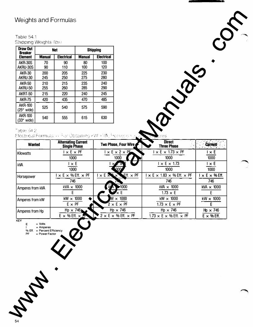
Weights and Formulas
Ta ble 54. 1 ShiPPing We1ghts i \ t)s 1
Draw Out Net Shipping Breaker Element Manual
AKR-30S 70 AKRU-30S 90
AKR-30 200 AKRU-30 245
AKR-50 210 AKRU-50 255
AKRT-50 215
AKR-75 420
AKR-100 525 (25" wide)
AKR-100 540 (33" wide)
:�-- r- ( ;r rn i . .i ·--··
Wanted
Kilowatts
. kVA
Horsepower
Amperes from kVA
Amperes from kW
Amperes from Hp
KEY E = Volts I = Amperes
Electrical Manual
90 80 1 1 0 100
205 225 250 275
21 5 235 260 285
220 240
435 470
540 575
555 615
� �J ! ' . ,
Alternating Current Single Phase
I X E X PF
1000
I X E --
1000
I X E X % Eft. X PF
746
kVA X 1000
E
kW X 1000
E x PF
Hp X 746
E X % Eft. X PF
% Elf. = Percent Efficiency PF = Power Factor
54
Electrical
1 00 120
230 280
240 290
245
485
590
630
\r d' "' ' ! ."'-� , ,
Two Phase, Four Wire
l x E x 2 x PF -
1000
I X E X 2
1000
I X E X 2 X % Eft. X PF
746
kVA X 1000
2 X E
kW x 1000
2 X E X PF
Hp X 746
2 X E X % Eft. X PF
; p �--�s Direct CUrrent Three Phase
I X E X 1 .73 X PF I X E 1000 1000
I X E X 1 .73 I X E 1000 1000
I X E X 1 .83 X % Eft. X PF I X E X % Eft. 746 746
kVA X 1000 kVA X 1000
1 .73 X E E
kW X 1000 kW X 1000
1 .73 X E X PF E Hp X 746 Hp X 746
1 .73 X E X % Eft. X PF E X % Eft.
www . El
ectric
alPar
tMan
uals
. com
www . El
ectric
alPar
tMan
uals
. com

Circuit breakers are designed primarily to perform the function of circuit interruption under shortcircuit conditions. Nevertheless, modern circuit breaker mechanisms are capable of many operations under fullload operation and in-rush conditions such as encountered in motor starting appli-
Ta!Jie 55 . '
Circuit Breaker Frame Size (Amperes)
225 800
1 600 2000 3200 4000
(A) Servicing consists of adjusting, cleaning, lubricat-ing, tightening, etc . , as rec-om mended by the manu-facturer. When current is interrupted, dressing of con-tacts may be required as well . The operations l isted are on the basis of servicing at intervals of six months or less.
(B) When closing and open-ing no-load.
(C) With rated control volt-age applied.
(D) Frequency of operation not to exceed 20 in ten min-utes or 30 in an hour. Rectifi-
cations. Industry standards have been established tor the minimum performance which is indicated in the table below. With adequate maintenance, GE breakers can be expected to exceed the standards.
Power operated circuit breakers, when operating
under usual service conditions, shall be capable of operating the number of times specified in the following table. The operating conditions and the permissible effect of such operations upon the breaker are given in the following lettered paragraphs. For each column, all paragraphs l isted in the
Number of Number of Operations Operations
Number of Related Continuous No-Load Operations Current Closing and Between Switching Opening Servicing (A) (C) (D) (E) (A) (B) (C) (D)
(F) (G) (H) and (J) (E) (F) and (G)
2500 4000 1 0000 1750 2800 9700
500 800 3200 500 800 3200 250 400 1 1 00 250 400 1 1 00
ers or other auxiliary devices tional part replacement and may further l imit the fre- general servicing may be quency of operation. necessary.
(E) Servicing at no greater (H) When closing and open-intervals than shown in ing current up to the contin-second column above. uous current rating of the
circuit breaker at voltages up (F) No functional parts to the rated maximum volt-should have been replaced age and at 85% of the power during the l isted operations. factor or higher.
(G) The circuit breaker {I) When closing currents should be in a condition to up to 600% and opening carry its rated continuous currents up to 100% (80% current at rated maximum power factor or higher) of the voltage and perform at least continuous current rating of one opening operation at the circuit breaker at volt-rated short-circuit current. ages up to the rated maxi-After completion of this mum voltage. series of operations, func- When closing currents
column heading must be given consideration . This standard applies to all parts of a circuit breaker that function during normal operation. It does not apply to other parts, such as overcurrent tripping devices, that function only during infrequent abnormal circuit conditions.
Number of Operations
In-Rush Current
Switching (C) (D) (E) (F) (G) (I) and (J)
2000 1400 400 400 -
-
up to 600% and opening currents up to 600% (50% power factor or less) of the continuous current rating of the circuit breaker at volt-ages up to rated maximum voltage, the number of oper-ations shown shall be re-duced to 10% of the number listed.
(J) I f a fault operation occurs before the completion of the l isted operations, servicing is recommended and possi-ble functional part replace-ments may be necessary, depending on previous accumulated duty, fault magnitude, and expected future operations.
55 www . El
ectric
alPar
tMan
uals
. com
www . El
ectric
alPar
tMan
uals
. com
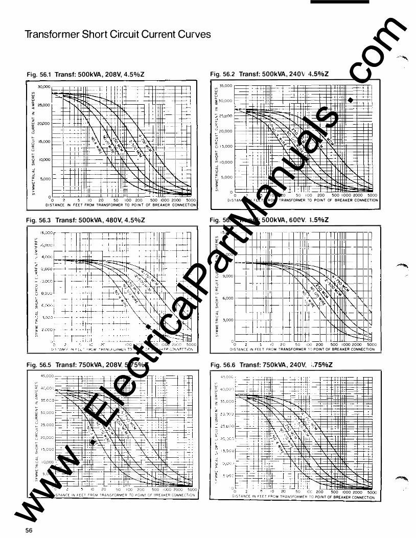
Transformer Short Circuit Current Curves
Fig. 56.1 Transf: 500kVA, 208V, 4.5%Z
30,000
"' w 0: w Q_
�--· •.. + -----+--
.... -- -----t-
....... -.... f- ------t-f-- --t-
,. 2�,000 <(
" -"'->-� 20P00 0: -- -0: ::> · --'-' >::: ::> 1�,000 '-' 0: u 1-0:
�� �� ,oct " c----f- "_\f-"'-o\ � ,.��o�'\o�<' f- "'o f-' � >-- � � � f--- '6� <},. f-
k-- C},. 1-' j! 10,000 "' --' <( '-' " � 0: 5,000 >-w ,.
" "
" " I" ,. ..... >-"'
0 0 5 I 0 20 50 100 200 500 1000 2000 5000
D I STANCE IN FEET FROM TRANSFORMER TO PO I N T OF BREAKER CONNECTION
Fig. 56.3 Transf: 500kVA, 480V, 4. 5%Z
1 0 0 2 C C' 5 0 0 IQ(XJ 2l '::"_!O 5000
Fig. 56.5 Transf: 750kVA, 208V, 5.75%Z
56
45,000
<n � 40,000--·
Q. "' � 3 5 ,0 0 0 -
f-� 30,000 ----r-- to: => � 2 5 , 0 0 0
::> u � 20,000 f------fCl: 0 ,;:; -" <i
1 5, 0 0 0 f---
u I 0,000 f-----er f-"' ::> "' Ci
5 , 000 �
0 0 10 20
r-¥ - -r-r
� 1- ..:.-=:::t= . ---+---t-t - · t-+
----t=
:--- f---J:=:t= j- +--
- t-:1=='-- j-"s.----;= j:=
50 1 00 zoo 500 1 000 2000 5000
D I S TANCE IN F E E T F R O M T R A N S FORME R TO P O I N T OF BREAKER CON N E C T I O N
Fig. 56.2 Transf: 500kVA, 240\i 4.5%Z "'
35,000 UJ :!', Q. ::> 30,000 <(
�
� 20,000
2 Cl: u 1 5 ,000 fa: 0 I "' 1 0,000 1---' <( u � 5,000 ::> "' �
0 0 I 0 20 5 0 I 00 200 500 I 000 2000 5000
D I S TA N C E' IN FEE T FROM TRANSFORMER TO POINT OF BREAKER CONNECTION
Fig. 56.4 Transf: 500kVA, 600V. 1 .5%Z
"' UJ 5 Q_ ,. <( � 1-z w 0: 0: ::> u f-=> u a: u f-a: 0 r "' -" <l u ii f-
� � "'
1 5,000
1 2 ,000
-
9,000
6,000
-3,000
f- -
0 0
I
1-·
r-
I
H-t t 1J
- f'::: ........
· -
· -t -
1 0 2 0
II II I
--....... I' � ;;--,
... >.,.
�""···� 1-0 "'- �"' ('� "<; ".._ 0� � 1\:
"!> "'"' <" I
\ r\ ,, "
I "'-..... 1---l ......_ t-t--
5 0 I 00 200 500 1000 2000 5000 D I S TA N C E IN FEE T FROM TRANSFORMER TO POINT OF BREAKER CONNEC T I O N
Fig. 56.6 Transf: 750kVA, 240V, i .75%Z 4 5,00C �I-,-
� =t-3 4-:J,oorJ --Q. "' <i ":
3 5 , 0 0 0 ______,
� <i
r:::L�, II .�� �u� : 0 � _L f=' .::± lf
0 1 0 20 50 IOC 200 500 1000 2000 5000 D I STANCE IN F E E T FROM TRANSFOR M E R TO POI N T OF BREAKER CONNECTION
www . El
ectric
alPar
tMan
uals
. com
www . El
ectric
alPar
tMan
uals
. com
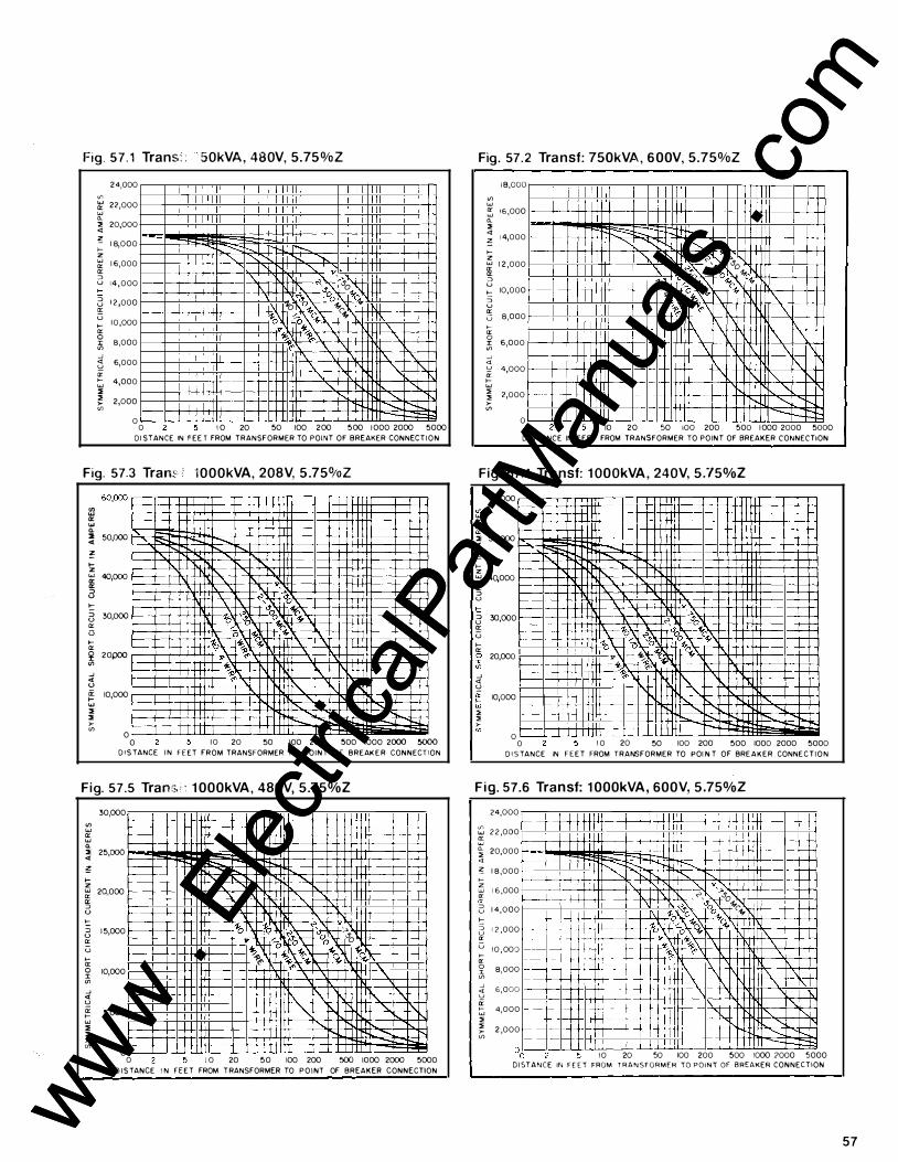
Fig. 5 7 . 1 Trans: : 50kVA , 480V, 5.75 % Z
if> w a: w 0.. ;,; <t ;;!: >-z w a: a: ::> u >-::> u � u >-a: 0 r "' _J <t " a: >-w ;,; ;,; ,.. "'
24,000
22,000
20,000
1 8,000
1 6,000
1 4 , 000
1 2 ,000
1 0 ,000
8,000
6,000
4,000
2,000
0 0
---..:::::t---"
1 0 20
\.
� " v '>
�'\ so .o�"'oo �'4, 1-o o � 1-0 m� �'4, r- ('.,. .. � 1\. � �\. 'S><" \. \. I"
\. \. \. \. \.
........ -......., -.....
50 100 200 500 I 000 2000 5000 D I STANCE IN FEE T FROM TRANSFORMER TO POINT OF BREAKER CONNECT I O N
Fig. 57.3 Tran:: i lOOOkVA, 208V, 5 .75%Z
[iJ a: w 0.. :1 50,000 '· <l � t-z w 40,000 a: a: ::> u '::: ::> 30,000 u a: i3 t-a:
� 20poo (/) _J <t u ii' 10,000 t-w ,. ,. ,.. (/)
0 0
D I S TANCE
"
I N
1 0 20 50 100 200 500 1000 2000 5000 FEET FROM TRANSFORMER TO P O I N T OF BREAK E R CONNECTION
Fig. 57.5 Tran•;· · 1 000kVA , 480V, 5.75%Z
(/) w a: w 0.. ,. <l
� t-z w a: a: ::> u
'::: ::> u a: u >-a: 0 :I: "' _J <t " a: >-w ;,; ;,; >-"'
30,000
25,000
20,000
1 5,000
10,000
5,000
0
- -f-
� --f-----
-f- ........: -r---f--- _ "'-,. \. '\. r-f-- ��\r v \�� <:.. �o �o'\ '-'so � � � c--�1\ .,.� 'S><" 1s><" -t,.� "
"\. "\. 1"\. '-... �
0 I 0 20 50 100 200 500 1000 2000 5000 D I S TANCE I N F E E T FROM T RANSFORMER TO P O I NT OF BREAKER CONNECTION
Fig. 57. 2 Transf: 750kVA , 6 00V, 5.75%Z
if> w a: w 0.. ;,; <t ;': >-� a: a:
3 '::: ::> u � u >-a: 0 r if> _J <t u ii' >-w ;,; ;,; >-if>
I B,OOO
1 6 ,000
1 4,000 � ::::---.... 1 2 ,000
10,000
8,000
6,000
4,000
2,000 - -0
1---' I'- '; � '>s
-zo '"'s sao o1,. 1o � 1,_ c.,. 0 � (' (' " 0 �� � � � � 'S><"\ '\ \ �
'\. \ \
" 1\.
1"-"
-......_ -r-0 10 20 50 100 200 500 1 000 2000 5000
D I STANCE IN F E E T FROM TRANSFORMER TO POINT OF BREAKER CONNECTION
Fig. 57.4 Transf: 1 000kVA , 240V, 5 ."/5%Z
"' w a: w 0.. ,. <l
� >-z w a: a: ::> u
t: ::> u 0: u >-0: 0 :I: "' _J <t " a: t;; ;,; ;,; >-"'
60,000
50,000
40,000
30,000
20,000
10,000
0 0
� ........ 1"\.. 1\..
to
� .. '_:.
<"', r--"'o b) .o) g"'o�c:.,'-�� � v - � 0� �1l � <" " "\.
'-...
1 0 20 50 100 200
' .....
500 1000 2000 5000
D I S TANCE IN F E E T FROM TRANSFORMER TO POI N T OF BRE A K E R CONNE C T I O N
Fig. 57.6 Transf: 1 000kVA , 600V, 5 .75%Z
"" w 5 0.. ;,; <t
;;!: >-if, a: cr 3 '::: ::> u cr u >--cr 0 I "' _J <l u � ;,; ;,; >-"'
24,000
r-- -2 2 ,000
20,000 r--1 8,000 f-- -1 6 ,000
f--I--1 4,000
1 2 ,000 ----1 0 , 000
--:::::) ----- -8,000 -� ---6,000
4,000 -- -2 ,000 --
--
--f- �-r--...-- �
" � '
t--t- -........_
b. _"'., "·> <", so
--f---1- �·�:�.r%.,_ �c.,.
f--- 1-o t '-c:.,�� " � � �� _\ � � f-
f-- \.
- -t- - - I t - -
I r--
--f--
\.
\. \. _::..,
" ....., ' ........_ 1---1 0 20 50 100 200 500 1000 ?000 5000
D I STANCE IN FEET FROM TRAN SFORMER TO POINT OF BREAKER CONNECTION
57
www . El
ectric
alPar
tMan
uals
. com
www . El
ectric
alPar
tMan
uals
. com
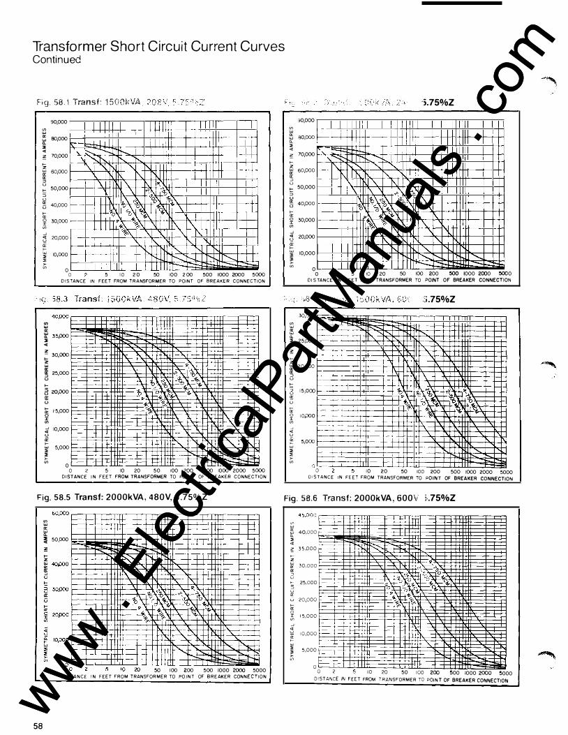
Transformer Short Circuit Current Curves Continued
F i g . 58 1 Transf: 1 5 001\VA
<f) "'
90,000
� 80,000 a. "' <t � 70,000
>z � 60,000 "' :::> u C: 50,000 :::> u G 4o,ooo
>--"' � 30,000 <f) _J � 20,000 "' >--� IOPOO " >-
1 1 lr- o-
'\ t:::----\ )'-. 1\.
r--1-----f---�-1-----
I f--....
r-.... "' !'-"'
\ �� ��:00 ��
• � � '< \ 0 0 �
I \ \\ I I '\
I I I I l i
-j)<" '\ __ '\ .....,_ !'--.. r--
-',+--
•
--f--1---\ I I\ 1\. )'-.
f'-.... ......... --"' I I O 0 5 I 0 2 0 50 100 2 00 500 1000 2000 5000 D I S TANCE IN FEET FROM T R A NSFORMER TO POINT OF BREAKER CONNECTION
"' "' "' � 35/XJO "' <t z - 30 000 � . "' a: !5 25,000 u >-a 2opoo � u � 1 5,000 0 J: <f) :;i 10,000 u ii >--"' " "'
>-"' 5,000
0
--f--
+--
- -f--
1--0 2 5 10 20 50 100 200 500 1000 2000 5000
D I STANCE I N FEET FROM TRANSFORMER TO PO I N T OF BREAKER CONNECTION
<f) UJ
30,000
5 80,000 a_ " <t � 70,000 >-z � sopoo "' ::J u >- 50,000 3 u i§ 40poo
>a: � 30,000 <f) _J ;3 20,000 i< � " " i:;
10,000
0
c--f---
E 1-- , I"
1\. 1\
·i.75%Z
I I I I !
l J ....... ! l .....,_ )'-. I', f...l " 1\ � -1
[\ "'�� 1o ��--�� 0�� - t-- 0 �� 0 ,. � � � 1\ \ % "
<" \ '\ 1\.
)'-. " ............ r--
1"-i'- .........
0 2 5 10 20 50 100 200 500 1000 2000 5000
<f) "' cr UJ a. "' <t "" >--z UJ cr cr :::> u >--:::> u a: u >--cr 0 :X: <f) _J <t u
� w " " >-<f)
Dl S TANCE IN F E E T FROM TRANSFORMER TO POINT OF BREAKER CONNECTION
30,000
25,000
20,000
1 5 ,000
10,000
5,000
J
':i .75%Z
- ....... " " "
\ t; �� :.��\ ,.
/ � �� 0 � '\ �� t-��t-1---- '\
1'- .......
0 10 20 50 100 200 500 1000 2000 5000 D I S TA N C E I N F E E T FROM TRANSFORMER TO PO I N T OF BREAKER CONNECTION
Fig. 58.5 Transf: 2000kVA , 480V, 5 .75%Z Fig . 58.6 Tra nsf: 2000kVA , 600\ i·.75%Z
58
"' "' a: "' a. � 50,000 �--
50 100 200 500 1000 2000 5000 D I S TA N C E I N FEET FROM TRANSFOR MER TO PO I N T OF B R E AKER CONN E C T I O N
vo w e5 40,000 a_ " <t � 3 5 ,000 >z :>' 30,000 cr ::J u >-- 25,000 :::> u a: u 20,000 f.-->-a: 0 .;:; 1 5,000 1-----_J
j 1 0,000 a:
� f::--" " >-V)
5,000
0 0 2 I 0 20 50 I 00 200 500 1000 2000 5000 D I STANCE IN FEET FROM TRANSFORMER TO POIN T OF BREAKER CONNECTION
www . El
ectric
alPar
tMan
uals
. com
www . El
ectric
alPar
tMan
uals
. com

,., , ,_ • 1c3n Na' · : Stand.:J:'"ds Jr��- 1
In Enclosures, Low-Voltage AC Power Circuit Breakers Used, ANSI / IEEE C37.13-1981 .
In Enclosures, Test Procedures for Low-Voltage AC Power Circuit Breakers Used, ANSI C37.50-1981 .
Low-Voltage AC NonIntegrally Fused Power Circuit Breakers (Using Separately Mounted CurrentLimiting Fuses), Application Guide for, ANSI / IEEE C37.27-1972.
Low-Voltage DC Power Circuit Breakers Used in Enclosures, ANSI / IEEE C37.14-1979.
Low-Voltage Power Circuit Breakers and AC Power Circuit Protectors, Preferred Ratings, Related Requirements and Application Recommendations for, ANSI / IEEE C37.16-1980.
Metal-Enclosed Low-Voltage AC Power Circuit Breaker Switchgear Assemblies, Conformance Testing of, ANSI C37.51-1 979.
Trip Devices for AC and General Purpose DC LowVoltage Power Circuit Breakers, ANSI C37.17-1979.
Order from: Sales Department American National
Standards Institute 1430 Broadway New York, NY 10018
of Etec.trica: and fV1anu factu rers Associa� ior· E i E ctrnnics (NEMA)
SG-3 1971 Low-Voltage Power Circuit Breakers
Order from: NEMA Publications 155 East 44th Street New York, NY 10017
(IEEE) No. 45 Recommended Practice for Electrical Installation on Shipboard.
Order from: IEEE Service Center 445 Hoes Lane Piscataway, New Jersey
08854.
National Electrical Code
1984 1ssue.
Order from: National Fire
Protection Association Batterymarch Park Quincy, MA 02269
59 www . El
ectric
alPar
tMan
uals
. com
www . El
ectric
alPar
tMan
uals
. com
G u ide Form Specifications General
The individually mounted low voltage power circuit breaker shall consist of an electrically and mechanically trip-free circuit breaker element.
The circuit breaker shall be of the draw-out type capable of being racked to the disconnect position with the door closed.
The circuit breaker shall meet ANSI C37. 1 3 , C37 . 1 6 and C37 .50 and be UL listed.
Interlocks will be provided to prevent connecting or disconnecting the circuit breaker unless the breaker is open. The breaker shall be prevented from being closed during any racking operation. A test position shall be provided to permit operating the breaker while it is disconnected from the power circuit.
MicroVersaTrip RMS-9 trip devices shal l i nclude:
• True rms current sensing for long time characteristics.
•· Time current characteristic adjustments of the fixedpoint type, gold plated for maximum reliability and setting accuracy.
• All internal solid-state circuitry of epoxy conformal coated to resist environmental contamination.
• Rating plugs for application flexibility.
• Adjustable current setting of 0.5 to 1 . 1 of sensor tap.
• Adjustable long-time delay with four bands.
• Integral long-time timing light.
• Adjustable instantaneous.
• I ntegral test provisions.
Optional c haracteristics
• True rms sensing for short time characteristics
• Short-time pick up and delay with Ft in or out
• High range instantaneous
• Ground fault pick up and delay with Ft in or out
• Self-powered overload, short circuit, and ground fault target indicators that continue to give indication even when control power has been lost
• Zone selective interlocking
Other AKR Circuit Breaker Publ ications General Installation and Maintenance
G E�)-5019 G EK-64459 G EK-64460 G EI-50299 G EK-7303 G EI-86135 GEK-7310
AKR-30S, AKRU-30S AKR-30/50/T50 AKR-75/100 and AKS-50 AK-25 AK-50, AKT-50, AK-75, -100 ECS/SST Supplement AKR-3/3A-50
Installation and Operating Installations
GEK-7302 G EI-86150 GEI-86151 G EI-86160 GEI-86157
60
AK-25/50, AKT-50, AK-75/1 00 AKR-30/50, AKRT-50 AKR-75/1 00 AKS-50, AKST-50 ECS, 1 8, 2A Trip Devices
Detailed
• This specification covers General Electric Company low voltage power circuit breakers, types AKA, AKRT, or AKRU.
• The continuous current frame ratings shall be 800, 1 600, 2000, 3200, 4000.
• Circuit breakers shall be manually or electrically operated.
• Control voltage for electrically operated breakers shall be :
• Volts: AC ______ _
3<!>-3W ____ _
Cycles -------
3<!>-4W ------
• Circuit breakers rms symmetrical interrupting ratings: 240VAC kA ______ _
480VAC kA ______ _
600VAC kA ______ _
250VDC kA -------
• Overcurrent trip devices shall be solid-state type MicroVersaTrip® RMS-9.
• Each solid-state trip unit shall be equipped with the following field adjustable time current characteristics.
-Adjustable current, and long-time delay -Integral long-time timing light -Instantaneous, standard or high range -Short-time pick up and delay with l2t in or out -Ground fault pick up and delay with l2t in or out -Target indicators, overload, short-circuit, and ground
fault
• Each circuit breaker shall be equipped with the following accessories:
-Shunt trip-Voltage _____ _
-Undervoltage release-Voltage _____ _
-Undervoltage release with time delay-Voltage _____ _
-Overload bell alarm switch -Lockout device -Auxiliary Switch:
Number of contacts: Normally open "a" type -----
Normally closed "b" type ___ _
-Operation counter
• Portable MicroVersaTrip RMS-9 test kit
Testing Instructions
GEK-64464 G EK-73300 G EK-64454 G EK-7309 GEK-7301
MicroVersaTrip Test Set TVTS1 ECS/SST Test Set TAK-TS2 ECS/SST Test Set TAK-TS1 Power Sensor High Current Testing Power Sensor Test Set
Renewal Parts
G EF-4527 GEF-4552 GEF-41 49 GEF-4150 GEF-4395 GEF-4396
AKR-30/50/T50 AKR-75/100 AK-25 AK-50 AK-75 AK-100 www .
Elec
tricalP
artM
anua
ls . c
om
www . El
ectric
alPar
tMan
uals
. com