columbia u spherical tokamak plasma...
TRANSCRIPT

ST2004-9/29-10/1/04 ST Science & Fusion Energy
Martin PengNSTX Program Director
Oak Ridge National Laboratory@ Princeton Plasma Physics Laboratory
Joint Spherical Torus Workshop andUS-Japan Exchange Meetings (STW2004)
29th September – 1st October, 2004Kyoto University
Yoshida-Honmachi, Kyoto, Japan
Spherical Tokamak Plasma Science & Fusion Energy Development
Supported by
Columbia UComp-X
General AtomicsINEL
Johns Hopkins ULANLLLNL
LodestarMIT
Nova PhotonicsNYU
ORNLPPPL
PSISNL
UC DavisUC Irvine
UCLAUCSD
U MarylandU Rochester
U WashingtonU Wisconsin
Culham Sci CtrHiroshima U
HISTKyushu Tokai U
Niigata UTsukuba U
U TokyoJAERI
Ioffe InstTRINITI
KBSIKAIST
ENEA, FrascatiCEA, Cadarache
IPP, JülichIPP, Garching
U Quebec
ST2004-9/29-10/1/04 ST Science & Fusion Energy
Spherical Tokamak (ST) Offers Rich Plasma Science Opportunities and High Fusion Energy Potential
• What is ST and why?• Scientific opportunities of ST
• How does shape (κ, δ, A …) determine pressure? • How does turbulence enhance transport?• How do plasma particles and waves interact?• How do hot plasmas interact with walls?• How to supply magnetic flux without solenoid?
• Contributions to burning plasmas and ITER• Cost-effective steps to fusion energy• Collaboration

ST2004-9/29-10/1/04 ST Science & Fusion Energy
Tokamak Theory in Early 1980’s Showed Maximum Stable βT Increased with Lowered Aspect Ratio (A)
• A. Sykes et al. (1983); F. Troyon et al. (1984) on maximum stable toroidal beta βT:
βTmax = C Ip / a ⟨B⟩ ≈ 5 C κ / A qj; ⟨B⟩ ≈ BT at standard AC ≈ constant (~ 3 %m·T/MA) ⇒ βN
⟨B⟩ = volume average B ⇒ BT
κ = b/a = elongationA = R0/a = aspect ratioqI ≈ average safety factor Ip = toroidal plasma currentBT ≈ applied toroidal field at R0
• Peng & Strickler (1986): What would happen to tokamak as A → 1?
− How would βN, κ, qj, change as functions of A?
Z
a ab
0 RR0
PlasmaCross
Section
ST2004-9/29-10/1/04 ST Science & Fusion Energy
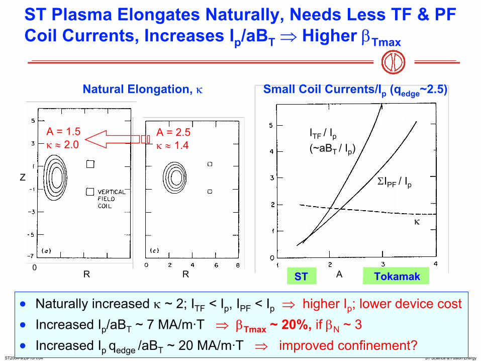
• Naturally increased κ ~ 2; ITF < Ip, IPF < Ip ⇒ higher Ip; lower device cost• Increased Ip/aBT ~ 7 MA/m·T ⇒ βTmax ~ 20%, if βN ~ 3• Increased Ip qedge /aBT ~ 20 MA/m·T ⇒ improved confinement?
ST Tokamak
ITF / Ip(~aBT / Ip)
ΣIPF / Ip
κ
Natural Elongation, κ Small Coil Currents/Ip (qedge~2.5)
R R A
Z
0
A = 2.5κ ≈ 1.4
A = 1.5κ ≈ 2.0
ST Plasma Elongates Naturally, Needs Less TF & PF Coil Currents, Increases Ip/aBT ⇒ Higher βTmax
ST2004-9/29-10/1/04 ST Science & Fusion Energy
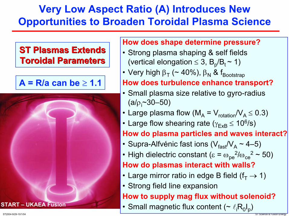
Very Low Aspect Ratio (A) Introduces New Opportunities to Broaden Toroidal Plasma Science
ST Plasmas ExtendsST Plasmas ExtendsToroidal ParametersToroidal Parameters
A = R/a can be ≥ 1.1
START – UKAEA Fusion
How does shape determine pressure?• Strong plasma shaping & self fields
(vertical elongation ≤ 3, Bp/Bt ~ 1)• Very high βT (~ 40%), βN & fBootstrapHow does turbulence enhance transport?• Small plasma size relative to gyro-radius
(a/ρi~30–50)• Large plasma flow (MA = Vrotation/VA ≤ 0.3)• Large flow shearing rate (γExB ≤ 106/s)How do plasma particles and waves interact?• Supra-Alfvénic fast ions (Vfast/VA ~ 4–5) • High dielectric constant (ε = ωpe
2/ωce2 ~ 50)
How do plasmas interact with walls?• Large mirror ratio in edge B field (fT → 1)• Strong field line expansionHow to supply mag flux without solenoid?• Small magnetic flux content (~ liR0Ip)
ST2004-9/29-10/1/04 ST Science & Fusion Energy
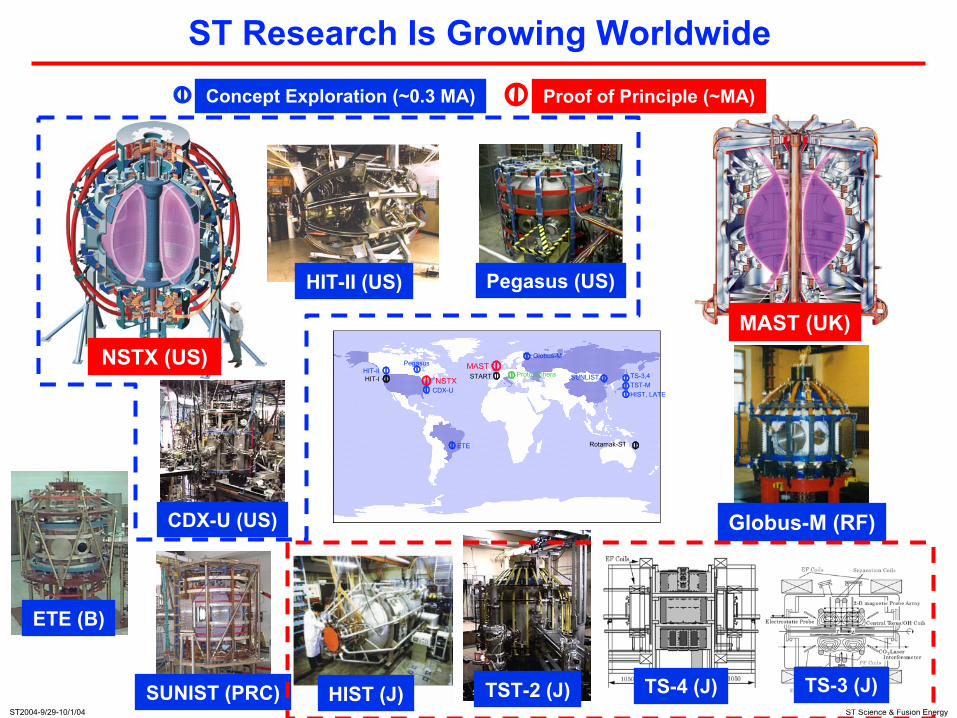
ST Research Is Growing Worldwide
HIST (J)
Globus-M
CDX-U
START TS-3,4TST-MHIST, LATE
Pegasus
ETE
MAST
NSTXHIT-II Proto-Sphera SUNLIST
Rotamak-ST
HIT-I
TST-2 (J) TS-3 (J)TS-4 (J)
Pegasus (US)
CDX-U (US)
NSTX (US)
HIT-II (US)
MAST (UK)
ETE (B)
SUNIST (PRC)
Proof of Principle (~MA)Concept Exploration (~0.3 MA)
Globus-M (RF)

ST2004-9/29-10/1/04 ST Science & Fusion Energy
Pegasus Explores ST Regimes As Aspect Ratio → 1
ST2004-9/29-10/1/04 ST Science & Fusion Energy
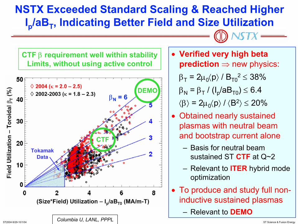
NSTX Exceeded Standard Scaling & Reached Higher Ip/aBT, Indicating Better Field and Size Utilization
• Verified very high beta prediction ⇒ new physics:βT = 2µ0⟨p⟩ / BT0
2 ≤ 38%βN = βT / (Ip/aBT0) ≤ 6.4⟨β⟩ = 2µ0⟨p⟩ / ⟨B2⟩ ≤ 20%
• Obtained nearly sustained plasmas with neutral beam and bootstrap current alone– Basis for neutral beam
sustained ST CTF at Q~2 – Relevant to ITER hybrid mode
optimization
• To produce and study full non-inductive sustained plasmas– Relevant to DEMO
Columbia U, LANL, PPPL
CTF β requirement well within stabilityLimits, without using active control
CTF
DEMOβN = 6
ST2004-9/29-10/1/04 ST Science & Fusion Energy
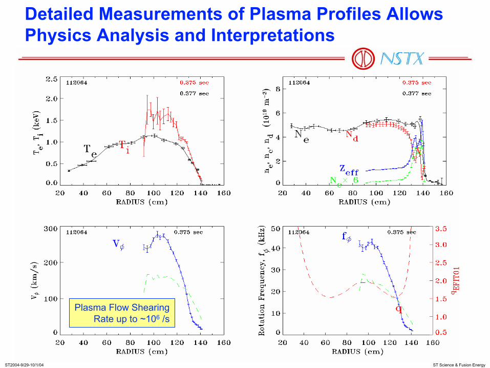
Detailed Measurements of Plasma Profiles Allows Physics Analysis and Interpretations
Plasma Flow ShearingRate up to ~106 /s

ST2004-9/29-10/1/04 ST Science & Fusion Energy
Strong Plasma Flow (MA=Vφ/VAlfvén~0.3) Has Large Effects on Equilibrium and Stability
• Internal MHD modes stops growing
• Pressure axis shifts out by ~10% of outer minor radius
• Density axis shifts by ~20%
0.4 0.6 0.8 1.0 1.2 1.4R(m)
0.0
0.2
0.4
0.6
0.8
1.0
1.2
1.4 107540 330ms
MA
Te(keV)
ne (m-3)4x10¹⁹
0.5 2.01.0 1.5
-2
-1
1
2
0
R(m)
Z(m
)
pressure surfacesmagnetic surfaces
Equilibrium Reconstruction with Flow
Columbia U, GA, PPPL, U Rochester

ST2004-9/29-10/1/04 ST Science & Fusion Energy
High-Resolution CHERS, SXR, and In-Vessel BR and BP Sensors Reveal Strong Mode-Rotation Interaction
CHarge-Exchange Recom-bination Spectroscopy
(CHERS) shows vφ collapsepreceding β collapse
SXR shows rotating 1/1mode during vφ decay
1/1 Island
In-vessel sensors measurerotating mode as vφ decays
before mode locking
Aliased n=1 rotating mode
RWM, NTM, 1/1 modes, and rotation physics of high interest to ITER
Sabbagh, Bell, Menard, Stutman
ST2004-9/29-10/1/04 ST Science & Fusion Energy
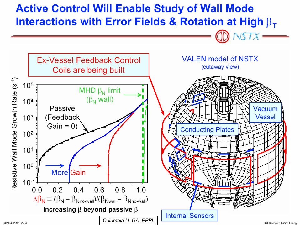
Active Control Will Enable Study of Wall Mode Interactions with Error Fields & Rotation at High βT
Columbia U, GA, PPPL
Res
istiv
e W
all M
ode
Gro
wth
Rat
e (s
-1)
Internal Sensors
Conducting Plates
Vacuum Vessel

ST2004-9/29-10/1/04 ST Science & Fusion Energy
Global and Thermal τE’s Compare Favorably with Higher A Database
• TRANSP analysis for thermal confinement
τ E<t
herm
al>
(ms)
τE<ITER-H98p(y,2)> (ms)
12080400
120
80
40
00.00 0.01 0.02 0.03 0.04 0.05
0.00
0.05
0.10
τ E<m
ag> [
s]
τE<ITER-97L> [s]
H-modeL-mode
x2.5
x1.5
• Compare with ITER scaling for total confinement, including fast ions
L-modes have higher non-thermal component and comparable τE! Why?Bell, Kaye, PPPL

ST2004-9/29-10/1/04 ST Science & Fusion Energy
Ion Internal Transport Barrier in Beam-Heated H-Mode Contrasts Improved Electron Confinement in L-Mode
Magnetic Axis
Kinetic Profile Local Error Sampling
Axis Edge
Regionsrequiringimproved
dataresolution
TransportBarrierregionwhere
χi ~ χiNC
andχe >> χi
Columbia U, Culham, ORNL, PPPL
But L-mode plasmas show improved electron confinement! Why?
L-mode H-mode
H-modeL-mode
T e(k
eV)
n e(1
013 /c
m3 )
iITB?
iITB?

ST2004-9/29-10/1/04 ST Science & Fusion Energy
Transport Analysis of NSTX Plasmas Using TRANSP Confirms This Contrast
• χe >> χi ~ χNCLASS in most H-mode• χe ~ χi in L-mode• Diagnostic Resolution improvements continue
L-mode
ST2004-9/29-10/1/04 ST Science & Fusion Energy
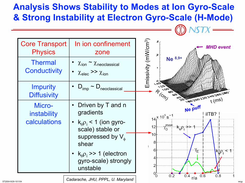
Analysis Shows Stability to Modes at Ion Gyro-Scale & Strong Instability at Electron Gyro-Scale (H-Mode)
Em
issi
vity
(mW
/cm
3 )
Ne 8,9+
MHD event
Ne pufft (ms)
R (cm)• Driven by T and n
gradients• kθρi < 1 (ion gyro-
scale) stable or suppressed by Vφshear
• kθρi >> 1 (electron gyro-scale) strongly unstable
Micro-instability
calculations
• Dimp ~ DneoclassicalImpurity Diffusivity
• χion ~ χneoclassical
• χelec >> χion
Thermal Conductivity
In ion confinement zone
Core Transport Physics
Cadarache, JHU, PPPL, U. Maryland
iITB?

ST2004-9/29-10/1/04 ST Science & Fusion Energy
A Broad Spectrum of Energetic Particle Driven Modes is Seen on NSTX
10
100
1000
0.1 0.2 0.3TIME (s)
FRE
QU
EN
CY
(kH
z)
“Fish-Bones”
TAE
CAE/GAE
108170
Do these Alfvén Eigenmodes (AEs) and fish-bones (f.b.s) Interact to expel energetic particles?
PPPL

ST2004-9/29-10/1/04 ST Science & Fusion Energy
TAE’s, “Fish-Bones,” and CAE/GAE’s Can Interact to Expel Energetic Particles
Synchronous sudden activities of• Edge Dα rises; D-D neutron drops• Fish-bone modes rises• TAE mode crashes• Separately, asynchronous drops of f.b.
and CAE modes• So far observed for βT ≤ 10% and Ip ≤
700 kA ⇒ high-β effects?• NPA measured depletion for 50-80 kV at
higher βT – MHD (m/n=4/2) induced?• Nonlinear effects relevant to lower β
burning plasmas (ITER)
H-alpha (a.u.)
Plasma Current (MW)
Pnbi (MW)
0.8
0.4
0.0
1.0
0.01.0
0.0
shot 108530
4
00.2 0.30.0 0.1 0.4
TIME (s)0.20 0.25 0.30
Neutrons (1014/s)
~rm
s(B
)
103
102
101
103
102
101
100
102
101
100
10-1CAE 500 - 1500 kHz
TAE 70 - 150 kHz
f.b. 10- 40 kHz
(Ip = 0.65 MA, Pb = 3.6 MW, βT = 10%)
PPPL

ST2004-9/29-10/1/04 ST Science & Fusion Energy
NSTX RF Research Explores High Dielectric (ε ~ 100) Effects for Efficient Heating & Current Drive
M. Ono (1995): High Harmonic Fast Wave (HHFW) decay (absorption) rate:
k⊥im ~ ne / B3 ~ ε / B,ε = ωpe
2 / ωce2 ~ 102
Laqua et al (1997): Conversion of oblique O-mode to slow X-mode to Electron Bernstein Wave (EBW):
Electromagnetic
Electrostatic
Over-densePlasma
Launcher/Receiver
&

ST2004-9/29-10/1/04 ST Science & Fusion Energy
HHFW: Heat Electrons and Trigger H-Modes, Relevant to Slowly Rotating ITER Plasmas
• Antenna operated in 6x(0-π) phasing for slow wave: kT ≈ 14m-1
0.5
0.0
0123
0
50
0.00.10.20.3
0.0 0.1 0.2 0.3 0.4 0.5Time [s]
PHHFW [MW]
WMHD, We [MJ]
ne(0), <ne> [1020m-3]
Ip [MA]
Hα [arb]
0.5 1.0 1.5Radius [m]
0.0
0.1
0.2
0.3
0.4
0
1
ne [1020m-3]
Te [keV]
0.243s
0.293s
0.343s
0.393s
0.243s
0.293s
0.343s
0.393s
LeBlanc

ST2004-9/29-10/1/04 ST Science & Fusion Energy
Frequency = 14 GHz
Electron Bernstein Wave: Oblique "O-X-B" Launch Is Resilient to Changes in Edge Density Gradient
• Optimum n// = 0.55; toroidal angle ~ 34o
from normal to B
• > 75% coupling for O-X-B antenna with ± 5 degree beam spread
EBW Coupling (%)80604020
OPTIPOL/GLOSI
Efficient conversion between ECW and EBW predicted.
ST2004-9/29-10/1/04 ST Science & Fusion Energy
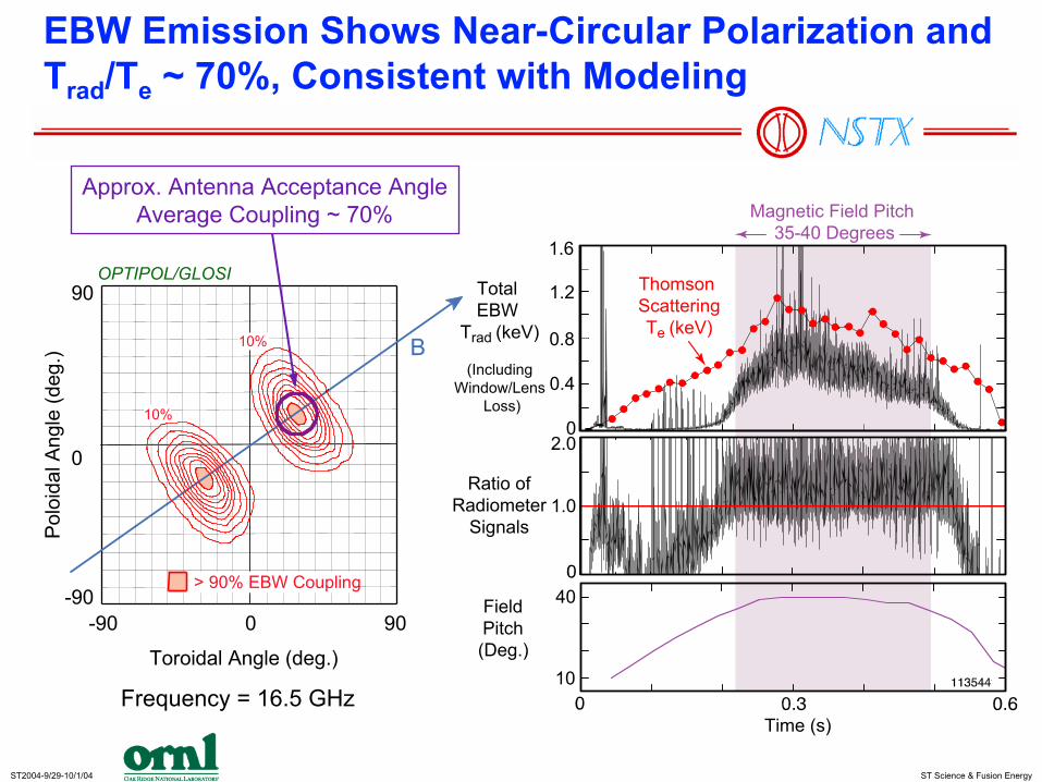
EBW Emission Shows Near-Circular Polarization and Trad/Te ~ 70%, Consistent with Modeling
0.4
1.6
1.2
0.8
0
1.0
2.0
ThomsonScatteringTe (keV)
TotalEBW
Trad (keV)
(IncludingWindow/Lens
Loss)
Ratio ofRadiometer
Signals
Time (s)
FieldPitch(Deg.)
10
40
Magnetic Field Pitch35-40 Degrees
Frequency = 16.5 GHz
OPTIPOL/GLOSI
Pol
oida
l Ang
le (d
eg.)
Toroidal Angle (deg.)
-90 900
0
-90
90
> 90% EBW Coupling
B
10%
10%
Approx. Antenna Acceptance AngleAverage Coupling ~ 70%
ST2004-9/29-10/1/04 ST Science & Fusion Energy
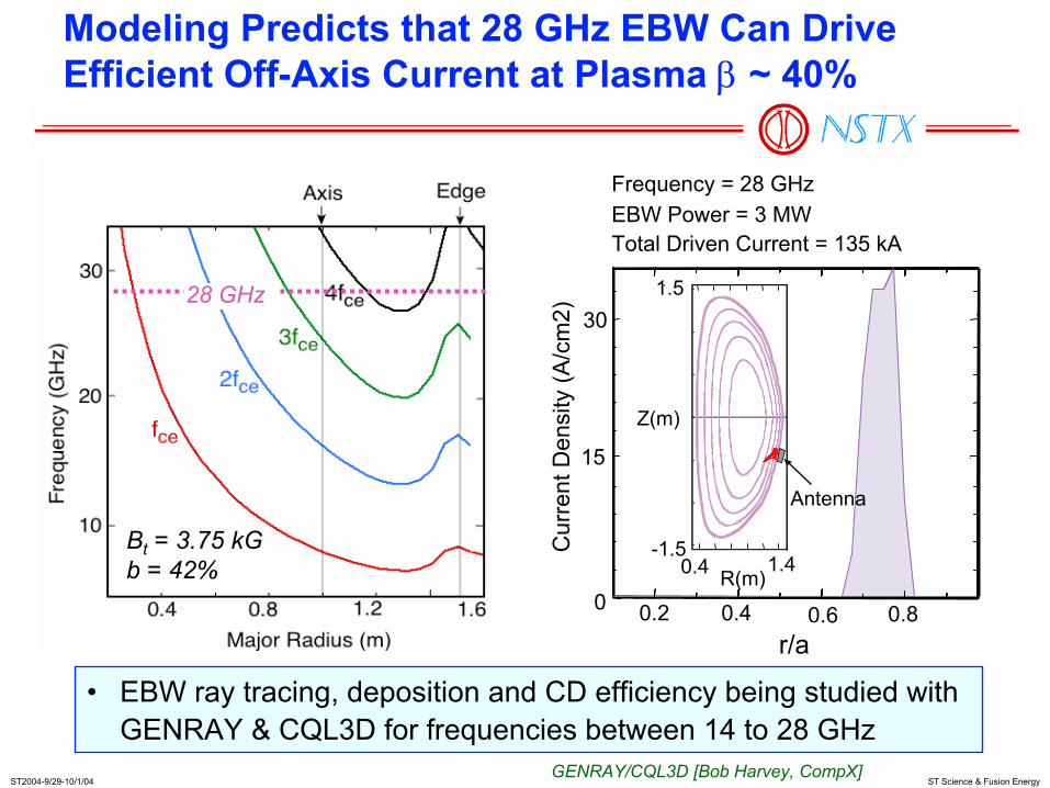
Bt = 3.75 kGb = 42%
28 GHz
Modeling Predicts that 28 GHz EBW Can Drive Efficient Off-Axis Current at Plasma β ~ 40%
• EBW ray tracing, deposition and CD efficiency being studied withGENRAY & CQL3D for frequencies between 14 to 28 GHz
GENRAY/CQL3D [Bob Harvey, CompX]
Frequency = 28 GHzEBW Power = 3 MWTotal Driven Current = 135 kA
30
15
0 0.2 0.80.60.4
1.5
Z(m)
-1.5R(m)
1.40.4
Antenna
r/a
Cur
rent
Den
sity
(A/c
m2)
ST2004-9/29-10/1/04 ST Science & Fusion Energy
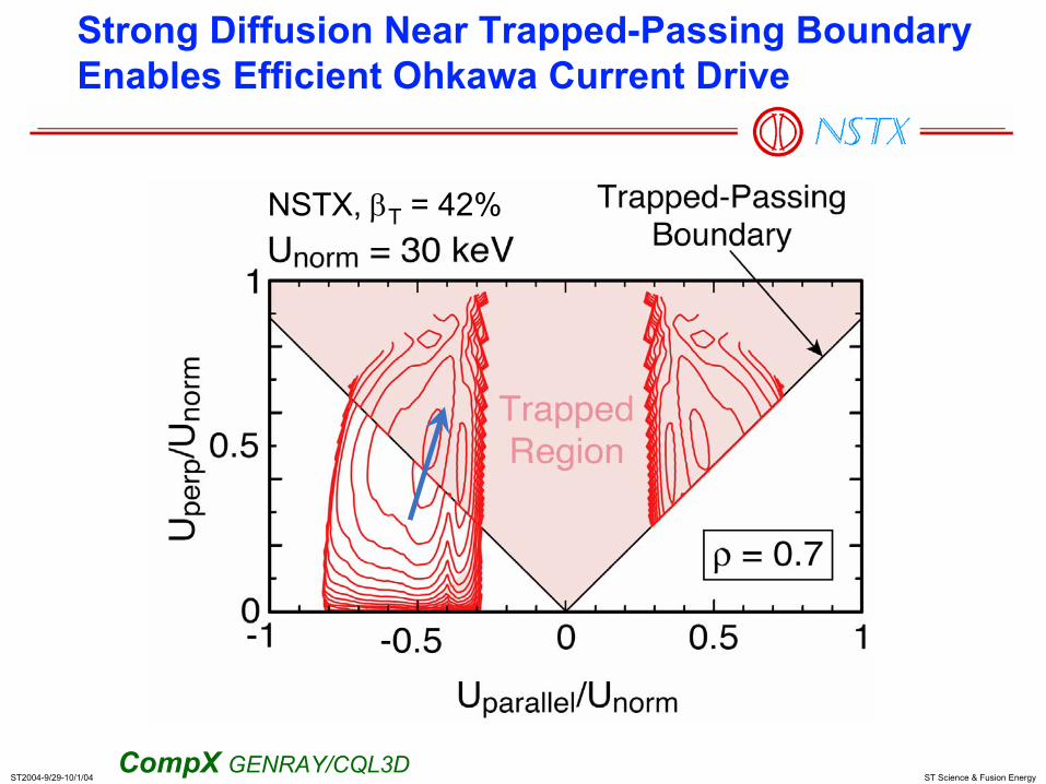
Strong Diffusion Near Trapped-Passing BoundaryEnables Efficient Ohkawa Current Drive
CompX GENRAY/CQL3D
NSTX, βT = 42%
ST2004-9/29-10/1/04 ST Science & Fusion Energy
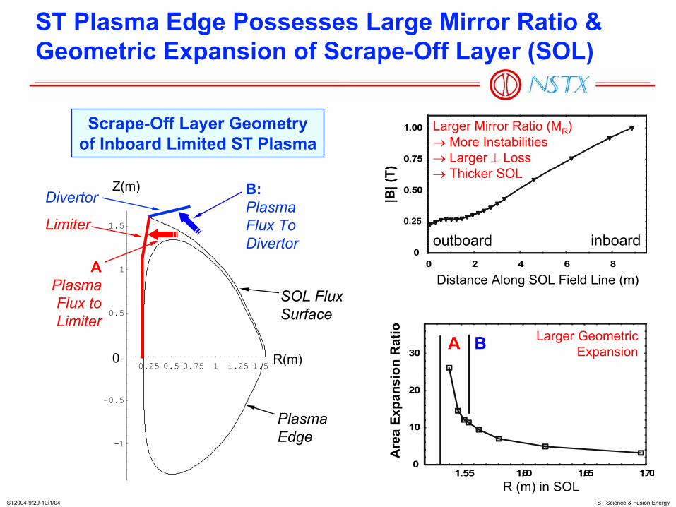
ST Plasma Edge Possesses Large Mirror Ratio &Geometric Expansion of Scrape-Off Layer (SOL)
0
10
20
30
1.55 1.60 1.65 1.70R (m) in SOL
A B
Are
a Ex
pans
ion
Rat
io Larger GeometricExpansion
0
0.50
0.75
1.00
0 2 4 6 8
Distance Along SOL Field Line (m)
inboardoutboard
|B| (
T)
Larger Mirror Ratio (MR)→ More Instabilities→ Larger ⊥ Loss→ Thicker SOL
Scrape-Off Layer Geometryof Inboard Limited ST Plasma
0.25 0.5 0.75 1 1.25 1.5
-1
-0.5
0.5
1
1.5
R(m)
Z(m)
0
APlasmaFlux toLimiter
Divertor
Limiter
SOL FluxSurface
PlasmaEdge
B:PlasmaFlux ToDivertor
ST2004-9/29-10/1/04 ST Science & Fusion Energy
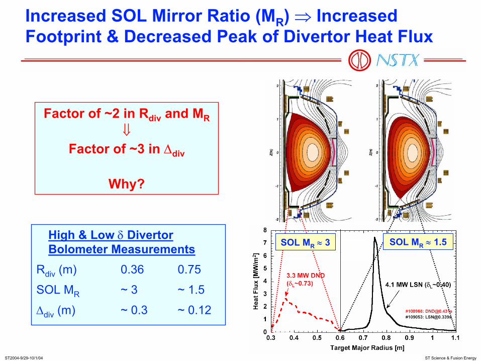
Increased SOL Mirror Ratio (MR) ⇒ Increased Footprint & Decreased Peak of Divertor Heat Flux
High & Low δ Divertor Bolometer Measurements
Rdiv (m) 0.36 0.75
SOL MR ~ 3 ~ 1.5
∆div (m) ~ 0.3 ~ 0.12
Factor of ~2 in Rdiv and MR⇓
Factor of ~3 in ∆div
Why?
SOL MR ≈ 3 SOL MR ≈ 1.5

ST2004-9/29-10/1/04 ST Science & Fusion Energy
Plasma Edge Studies Reveal Turbulence and“Blobs” Important to Divertor Flux Scaling Studies
He manifold
Side-viewingreentrant window
H-mode
L-mode
Broadly Based Study:• Gas Puff Imaging
views along field lines (PPPL, LANL)
• Very fast camera, 105/s (PSI)
• Reflectometers and edge (UCLA, ORNL)
• Reciprocating probe(UCSD)
• Divertor fast camera(Hiroshima U)
• IR Cameras (ORNL), Filterscope (PPPL)
• Modeling (PPPL, UCSD, LLNL, Lodestar)
105710

ST2004-9/29-10/1/04 ST Science & Fusion Energy
Tray after ~40 discharges.
Liquid lithium tray limiter in CDX-U
CDX-U Is Testing Innovative Lithium Plasma Facing Component Effects, to Control Recycling
• First successful test of toroidal liquid lithium tray limiter• Dramatic reduction in plasma edge fuel recycling, lowering impurity
influx and loop voltage• NSTX tests of lithium pellets and lithium wall coating in 2004
PPPL, UCSD, ORNL, SNL
ST2004-9/29-10/1/04 ST Science & Fusion Energy
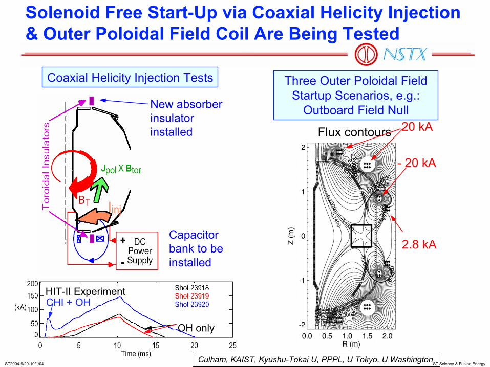
CHI + OH
OH only
HIT-II Experiment
Culham, KAIST, Kyushu-Tokai U, PPPL, U Tokyo, U Washington
New absorber insulator installed
Capacitor bank to be installed
Three Outer Poloidal Field Startup Scenarios, e.g.:
Outboard Field Null
Flux contours 20 kA
- 20 kA
2.8 kA
Coaxial Helicity Injection Tests
Solenoid Free Start-Up via Coaxial Helicity Injection & Outer Poloidal Field Coil Are Being Tested

ST2004-9/29-10/1/04 ST Science & Fusion Energy
JT-60U Tests on Solenoid-Free Start-Up via RF and NBI Offers Additional Exciting Opportunities
Startup RF + NBI
RF Ramp-up
U. Tokyo, JT-60U – JAERI
• JT-60U: from 200 kA to 700 kA with LHW + NBI (2002)
• PLT: 100 kA with LHW (1980s)
• CDX-U, TST-2: up to 4 kA with ECH
• MAST: 1-MW ECH
• NSTX: to develop and test up to 4-MW EBW in 5 years
• Utilize outer PF coil induction with simple ramp

ST2004-9/29-10/1/04 ST Science & Fusion Energy
High βT
High τE
Co-NBI plasmas:• Improved vertical
control ⇒ higher κ
• βp t 1 and IBS/Ip d 0.5
• βN ~ 6 and βT > 20%
• Reduced VL
• Help developing ITER hybrid scenario
• Driven steady state ST plasmas (CTF).
• Need to reduce ELM size
Nearly Sustained Plasmas with Broader Values of κ, li, Ip, and βT Can Contribute to ITER Hybrid Scenario

ST2004-9/29-10/1/04 ST Science & Fusion Energy
NSTX Made Large Progress in Producing and Studying the Science of Attractive Sustained Plasmas
FY01-03
• EFIT02• Peak βT• All shapes
NSTX Potential
FY04
Frac
tion
of S
elf-D
riven
Cur
rent
f B
S~
0.5
×ε½
β P

ST2004-9/29-10/1/04 ST Science & Fusion Energy
Long-Pulse H-Mode Plasmas Made Large Progress in Physics Basis for Next-Term ST Science Facilities
Well positioned to address the science of sustained high-performance plasmas.
ARIES-AT (4MW/m2)
CTF-ST}
τpulse/τE Normalized pulse length
Nor
mal
ized
bet
a x
norm
aliz
ed c
onfin
emen
t NSTX OperationARIES-ST (4WM/m2)
4
2
1MW/m2
NSST

ST2004-9/29-10/1/04 ST Science & Fusion Energy
Research Topics to Achieve Long-Pulse, High Performance Plasmas Are Identified
• Enhanced shapingimproves ballooning stability
• Mode, rotation, and error field control ensures high beta
• NBI and bootstrap sustain most of current
• HHFW heating may contribute to bootstrap
• EBW provides off-axis current & stabilizes tearing modes
• Particle and wall control maintains proper density
CompX, MIT, PPPL, ORNL, UCSD

ST2004-9/29-10/1/04 ST Science & Fusion Energy
Answering the Plasma Science Questions Also Enable Cost-Effective Steps toward Fusion Energy
Smaller unit size for sustained fusion burn
⇒How does turbulence enhance transport?
Efficient fusion α particle, neutral beam, & RF heating
⇒How does plasma particles and waves interact?
Simplified smaller design, reduced operating cost
⇒How to supply magnetic flux without solenoid?
Lowered magnetic field and device costs
⇒How does shape determine pressure?
Survivable plasma facing components
⇒How do hot plasmas interact with wall?
Optimize Fusion DEMO & Development Steps
⇒Plasma Science Questions in Extended ST Parameter Space
ST2004-9/29-10/1/04 ST Science & Fusion Energy
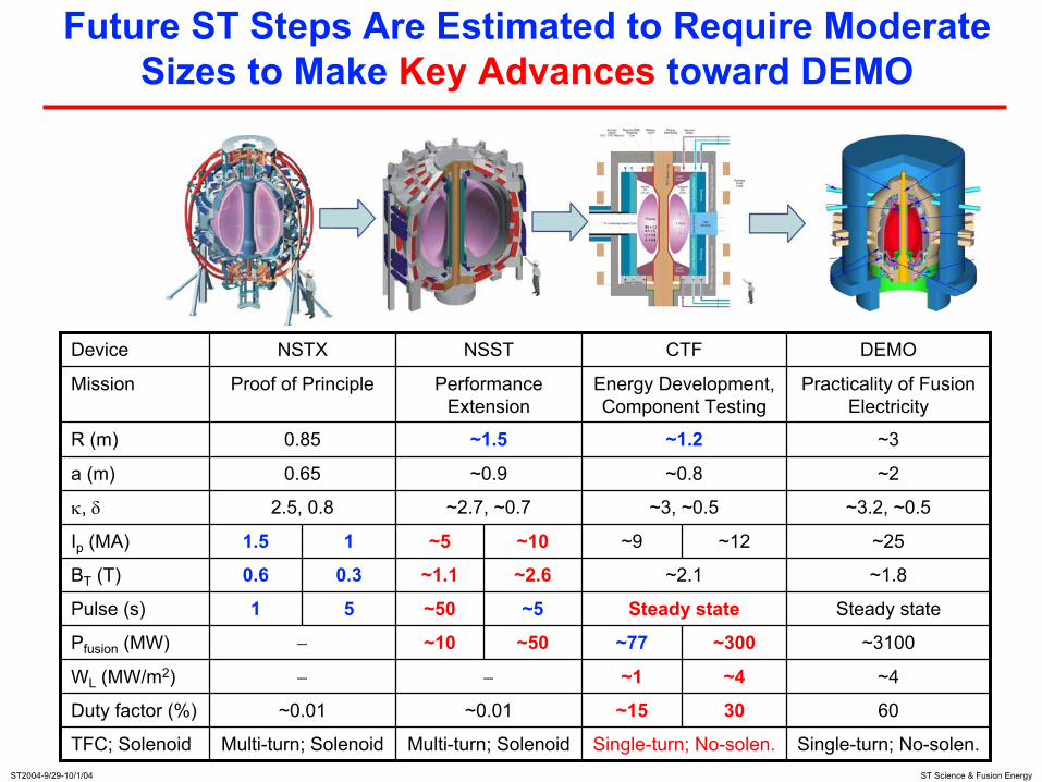
Future ST Steps Are Estimated to Require Moderate Sizes to Make Key Advances toward DEMO
6030~15~0.01~0.01Duty factor (%)
~2.1
~12
~4
~300~50
~5
~2.6
~10
0.3
1
5
Single-turn; No-solen.Single-turn; No-solen.Multi-turn; SolenoidMulti-turn; SolenoidTFC; Solenoid
~4~1−−WL (MW/m2)
~3100~77~10−Pfusion (MW)
Steady stateSteady state~501Pulse (s)
~1.8~1.10.6BT (T)
~25~9~51.5Ip (MA)
~3.2, ~0.5~3, ~0.5~2.7, ~0.72.5, 0.8κ, δ
~2~0.8~0.90.65a (m)
~3~1.2~1.50.85R (m)
Practicality of Fusion Electricity
Energy Development, Component Testing
Performance Extension
Proof of PrincipleMission
DEMOCTFNSSTNSTXDevice

ST2004-9/29-10/1/04 ST Science & Fusion Energy
ST Research Has Broad and Growing Opportunities for Collaborations
• Exploratory ST’s in Japan– TST-2: ECW-EBW initiation– TS-3,4: FRC-like β~1 ST plasmas– HIST: helicity injection physics– LATE: solenoid-free physics
• Active participation in ITPA (ITER)– A and β effects on confinement, ITB,
ELM’s, pedestal, SOL, RWM, and NTM; scenarios, window coating, etc.
• ST Database with MAST, U.K.– NBI H-mode, transport, τE
– EBW H&CD (1 MW, 60 GHz), FY03– Divertor heat flux studies, FY03-04– NTM, ELM characterization
• DIII-D & C-Mod collaboration– Joint experiments: RWM, Fast ion
MHD, pedestal, confinement, edge turbulence, X-ray crystal spectrometer
• MST: electromagnetic turbulence, EBW
C-Mod (U.S.)DIII-D (U.S.)
MST (U.S.)
MAST (U.K.)

ST2004-9/29-10/1/04 ST Science & Fusion Energy
Spherical Tokamak (ST) Offers Rich Plasma Science Opportunities and High Fusion Energy Potential
• Early MHD theory suggested ST could permit high β, confirmed recently by experiments
• Recent research identified new opportunities for addressing key plasma science issues using ST• Results have been very encouraging in many scientific
topical areas
• ST research contributes to burning plasma physics optimization for ITER
• ST enables cost-effective steps toward practical fusion energy
• ST research is highly collaborative worldwide

ST2004-9/29-10/1/04 ST Science & Fusion Energy
Backup VUs

ST2004-9/29-10/1/04 ST Science & Fusion Energy
Minimizing Tokamak Aspect Ratio Maximizes Field Line Length in Good Curvature ⇒ High β Stability
Tokamak Compact Toroid (CT)
Spherical Tokamak (ST)
Bad CurvatureGood Curvature
Magnetic Field LineMagnetic Surface
Small-R close to Tokamak & large-R close to CT.

ST2004-9/29-10/1/04 ST Science & Fusion Energy
ST Is Closest to Tokamak; Operates with High Safety Factor and More Comparable Self & Applied Fields
Field Reversed Configuration
Reversed Field PinchDipole
Spheromak
Impr
ove
Plas
ma
Stab
ility
at H
igh
β→
0A
vera
ge S
afet
y fa
ctor
, qav
g5
ExampleExampleFusion ConfigurationsFusion Configurations
Spherical Tokamak(Spherical Torus)
(NSTX, MAST, TST-2,TS-3,4, HIST, LATE, etc.)
Tokamak &Advanced Tokamak
(DIII-D, C-Mod,K-Star, JT60-U, etc.)
Stellarators(QPS)In Design
(NCSX)Being Built
0.5 (Applied Field)/(Applied + Plasma-Produced Field) 1(Self-Organized) Increase Controllability → (Externally Controlled)
(LDX, etc.)
(SSPX, etc.)
(MST, etc.)
(LDX, etc.)
LHD

ST2004-9/29-10/1/04 ST Science & Fusion Energy
In MAST, However, Counter NBI Reduces Electron Energy Loss
High flow shear scenario on MAST (Co- & Counter-NBI)
• Counter-NBI produces stronger ωSE ~ 106 s-1 and strong local reduction in χe at broader radius
• Pressure gradient contribution to Er reinforces that due to Vφ with ctr-NBI
• Strong ExB flow shear and weak magnetic shear s ~ 0 produced by NBI heating during current ramp
• With co-NBI ion thermal transport reduced to N.C. level χi ~ χi
NC
with weaker reduction in χe
• Strong ExB flow shear ωSE > γm
ITG and s ~ 0 at minimum of χi,e
0.0 0.2 0.4 0.6 0.8 1.00
3
4
5
2
1
0.0
1.5
1.0
0.5
ρ
[keV
]
ne
Ti
Te
.2 s
0.0 0.2 0.4 0.6 0.8 1.00
3
4
5
2
1
0.0
1.5
1.0
0.5
ρ
[10
19 m
-3]
#8302, 0.2 s
0.0 0.2 0.4 0.6 0.8 1.0
ρ
[m
2 s
-1]
8575, 0.2 s
1.0
100
10
0.1
χi
χeNC
0.0 0.2 0.4 0.6 0.8 1.0
ρ
#8302, 0.2 s
1.0
100
10
0.1
#8
χφ
χiN
#830
Co-NBI Counter-NBI
ST2004-9/29-10/1/04 ST Science & Fusion Energy
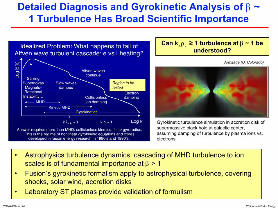
Detailed Diagnosis and Gyrokinetic Analysis of β ~ 1 Turbulence Has Broad Scientific Importance
Can k¦ρι ≥ 1 turbulence at β ~ 1 be understood?
Region to be tested
Armitage (U. Colorado)
• Astrophysics turbulence dynamics: cascading of MHD turbulence to ion scales is of fundamental importance at β > 1
• Fusion’s gyrokinetic formalism apply to astrophysical turbulence, covering shocks, solar wind, accretion disks
• Laboratory ST plasmas provide validation of formulism
Gyrokinetic turbulence simulation in accretion disk of supermassive black hole at galactic center, assuming damping of turbulence by plasma ions vs. electrons
ST2004-9/29-10/1/04 ST Science & Fusion Energy
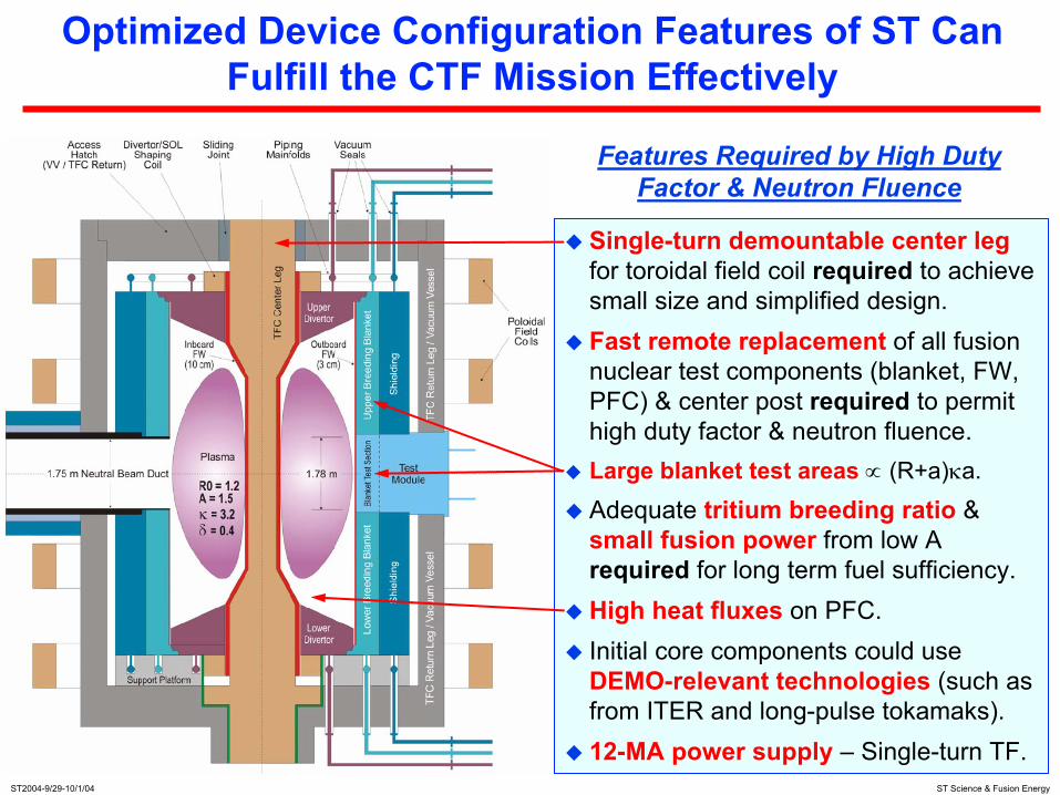
Single-turn demountable center leg for toroidal field coil required to achieve small size and simplified design.Fast remote replacement of all fusion nuclear test components (blanket, FW, PFC) & center post required to permit high duty factor & neutron fluence.Large blanket test areas ∝ (R+a)κa.
Adequate tritium breeding ratio & small fusion power from low Arequired for long term fuel sufficiency.High heat fluxes on PFC.Initial core components could use DEMO-relevant technologies (such as from ITER and long-pulse tokamaks).12-MA power supply – Single-turn TF.
Features Required by High DutyFactor & Neutron Fluence
Optimized Device Configuration Features of ST Can Fulfill the CTF Mission Effectively