colour television chassis em3e - reptips.dk em3e.pdf · gb 2 1. em3e technical specifications,...
TRANSCRIPT
Published by CO 0066 Service PaCE Printed in the Netherlands Subject to modification � 3122 785 11360
©Copyright 2001 Philips Consumer Electronics B.V. Eindhoven, The Netherlands.All rights reserved. No part of this publication may be reproduced, stored in aretrieval system or transmitted, in any form or by any means, electronic, mechanical,photocopying, or otherwise without the prior permission of Philips.
Colour television Chassis
EM3EAA
CL 16532044_000.eps150501
Contents Page Contents Page1 Technical Specifications, Connection Facilities 2
and Chassis Overview2 Safety Instructions, Maintenance, 4
Warnings and Notes3 Directions for Use 64 Mechanical Instructions 205 Service Modes, Error Codes, 23
Faultfinding and Repair Tips.6 Block Diagrams
Block Diagram (Supply, Deflection) 35Block Diagram (SSB Video) 36Block Diagram (SSB Audio) 37Supply Lines Overview 38Wiring Diagram 39I2C Overview 40Testpoint Overviews 41
7 Electrical Diagrams and PWB lay-outs Diagram PWBMain Supply (Diagram A1) 42 51-56Stand-by Supply (Diagram A2) 43 51-56Line Deflection (Diagram A3) 44 51-56Frame Deflection E/W Drive (Diagram A4) 45 51-56Rotation Circuitry (Diagram A5) 46 51-56Audio Amplifier (Diagram A6) 47 51-56Headphone Amplifier (Diagram A7) 46 51-56Tuner, I/O, SIMM (Female) (Diagram A8) 48 51-56Front (Diagram A10) 49 51-56Inputs / Outputs (Diagram A11) 50 51-56SIMM (Male) (Diagram B1) 57 64-73IF, I/O, Video Processing (Diagram B2) 58 64-73Featurebox (PICNIC) (Diagram B3) 59 64-73Video Control (HOP) (Diagram B4) 60 64-73Teletext & Control (OTC) (Diagram B5) 61 64-73Audio Demodulator (Diagram B6) 62 64-73Falconic (Diagram B8) 62 64-73
Mains Switch Panel (Diagram E) 74 74-75CRT Panel (Diagram F) 76 77DC-Shift Panel (Diagram G) 78 78I/O 3rd SCART Panel (Diagram H) 80 81VDAF + 2nd Order S Panel (Diagram I) 82 83Side I/O Panel (Diagram O) 84 85Top Control (Diagram P) 86 86
8 Electrical Alignments 879 Circuit Descriptions 94
List of Abbreviations 10910 Spare Parts List 111

Technical Specifications, Connection Facilities and Chassis OverviewGB 2 EM3E1.
1. Technical Specifications, Connection Facilities and ChassisOverview
1.1 Technical Specifications
1.1.1 Reception
Tuning system : PLLColour systems : PAL B/G, D/K, I
: SECAM B/G, D/K,L/L’
: NTSC 4.43(playback only)
Sound systems : FM-mono B/G: FM-mono D/K: FM-mono I: AM-mono L/L’: 2CS B/G: 2CS/Chez D/K: NICAM B/G: NICAM D/K: NICAM I: NICAM L
A/V connections : PAL B/G, D/K, I: SECAM B/G, D/K,
L/L’: NTSC 4.43
(playback only)Channel selections : 100 channels
: VHF, UHF, S-Channels andHyperband
Aerial input : 75 �, CoaxVCR preselections : 0 and 90 - 99
1.1.2 Miscellaneous
Mains voltage : 220 - 240 V (� 10 %)Mains frequency : 50 / 60 Hz (� 5 %)Ambient temperature : + 5 to + 45 deg. CMaximum humidity : 90 % R.H.Standby Power consumption : 1 W
1.2 Connection Facilities
1.2.1 Front Controls / Side Connections
Figure 1-1
Audio / Video In- - Video CVBS (1 Vpp / 75 �) ��
- - Audio L (0.5 Vrms / 10 k�) ��
- - Audio R (0.5 Vrms / 10 k�) ��
- - Headphone (32 - 2000 � / 10 mW) ��
SVHS (in)1 - GND �
2 - GND �
3 - Y (1 Vpp / 75 �) �
4 - C / 16:9 (0.3 Vpp / 75 �) �
5 - GND �
1.2.2 Rear Connections
Figure 1-2
Audio Out- - Audio Surr. (0.5 Vrms / 1 k�) ��
- - Audio L (0.5 Vrms / 1 k�) ��
- - Audio R (0.5 Vrms / 1 k�) ��
External 1 (in/out): RGB/YUV + CVBS
Figure 1-3
1 - Audio R (0.5 Vrms / 1 k�) �
2 - Audio R (0.5 Vrms / 10 k�) �
3 - Audio L (0.5 Vrms / 1 k�) �
4 - GND �
5 - GND �
6 - Audio L (0.5 Vrms / 10 k�) �
7 - Blue / U (0.7 Vpp / 75 �) �
8 - CVBS-status 0 - 1.3 V: INT4.5 - 7 V: EXT 16:99.5 - 12 V: EXT 4:3
9 - GND �
10-11- Green / Y (0.7 Vpp / 75 �) �
12-13- GND �
14- GND �
15- Red / V (0.7 Vpp / 75 �) �
16- RGB-status 0 - 0.4 V: INT 1 - 3 V: EXT / 75 �
17- GND �
18- GND �
19- CVBS (1 Vpp / 75 �) �
20- CVBS (1 Vpp / 75 �) �
21- Earth GND ��
CL16532044_001.eps260401
SVHSVIDEOAUDIO LAUDIO R
3.5
SK 1 IR-RECEIVER
FRONT CONTROL SIDE I/O
STANDBY LED
CL16532044_002.eps090501
AUDIO OUT
SURR.
L
R
EXT1
EXT2
EXT3
SERVICECONNECTOR
1 21
202CL96532137_056.eps
171199

Technical Specifications, Connection Facilities and Chassis Overview GB 3EM3E 1.
External 2 (in/out): SVHS + CVBS (intended for VCR)
Figure 1-4
1 - Audio R (0.5 Vrms / 1 k�) �
2 - Audio R (0.5 Vrms / 10 k�) �
3 - Audio L (0.5 Vrms / 1 k�) �
4 - GND �
5 - GND �
6 - Audio L (0.5 Vrms / 10 k�) �
7 - C (0.7 Vpp / 75 �) �
8 - CVBS-status 0 - 1.3 V: INT4.5 - 7 V: EXT 16:99.5 - 12 V: EXT 4:3
9 - GND �
10- Easy link (P50)11-12-13- GND �
14- GND �
15- C (0.7 Vpp / 75 �) �
16-17- GND �
18- GND �
19- CVBS (1 Vpp / 75 �) �
20- Y / CVBS (1 Vpp / 75 �) �
21- GND �
External 3 (in): CVBS
Figure 1-5
1 -2 - Audio R (0.5 Vrms / 10 k�) �
3 -4 - GND �
5 - GND �
6 - Audio L (0.5 Vrms / 10 k�) �
7 -8 - CVBS-status 0 - 1.3 V: INT
4.5 - 7 V: EXT 16:99.5 - 12 V: EXT 4:3
9 - GND �
10-11-12-13- GND �
14- GND �
15-16-17- GND �
18- GND �
19-20- CVBS (1 Vpp / 75 �) �
21-
1.3 Chassis Overview
Figure 1-6
1 21
202CL96532137_056.eps
171199
1 21
202CL96532137_056.eps
171199
CL 16532044_004.eps140501
TOP CONTROL PANEL
MAINSWITCH PANEL
LARGE SIGNAL PANEL
SMALL SIGNAL BOARD
SIDE I/O PANEL
CRT/SCAVEM PANELF
O
3rd SCARTH
B
P
E
P
A
DAF PANEL I

Safety & Maintenance instructions, Warnings and NotesGB 4 EM3E2.
2. Safety & Maintenance instructions, Warnings and Notes
2.1 Safety instructions for repairs
Safety regulations require that during a repair:• Due to the chassis concept, a very large part of this
chassis (incl. deflection) is 'hot'. Therefore the set mustbe connected to the mains via an isolating transformer.
• Safety components, indicated by the symbol�, shouldbe replaced by components identical to the original ones.
• When replacing the CRT, safety goggles must be worn.
Safety regulations require that after a repair, the set must bereturned in its original condition. In particular attention shouldbe paid to the following points:• General repair instruction: as a strict precaution, we
advise you to resolder the solder joints, through whichthe horizontal deflection current is flowing, in particular:– All pins of the line output transformer (LOT);– Fly-back capacitor(s);– S-correction capacitor(s);– Line output transistor;– Pins of the connector with wires to the deflection coil;– Other components through which the deflection
current flows.Note: This resoldering is advised to prevent bad connectionsdue to metal fatigue in solder joints and is therefore onlynecessary for television sets older than 2 years.• The wire trees and EHT cable should be routed correctly
and fixed with the mounted cable clamps.• The insulation of the mains lead should be checked for
external damage.• The mains lead strain relief should be checked for its
function in order to avoid touching the CRT, hotcomponents or heat sinks.
• The electrical DC resistance between the mains plug andthe secondary side should be checked (only for setswhich have a mains isolated power supply). This checkcan be done as follows:– Unplug the mains cord and connect a wire between
the two pins of the mains plug;– Set the mains switch to the 'ON' position (keep the
mains cord unplugged!);– Measure the resistance value between the pins of
the mains plug and the metal shielding of the tuner orthe aerial connection on the set. The reading shouldbe between 4.5 M� and 12 M�.
– Switch off the TV and remove the wire between thetwo pins of the mains plug.
• The cabinet should be checked for defects to avoidtouching of any inner parts by the customer.
2.2 Maintenance instructions
It is recommended to have a maintenance inspection carriedout by a qualified service employee. The interval depends onthe usage conditions:• When the set is used under normal circumstances, for
example in a living room, the recommended interval is 3to 5 years.
• When the set is used in circumstances with higher dust,grease or moisture levels, for example in a kitchen, therecommended interval is 1 year.
• The maintenance inspection contains the followingactions:– Execute the above-mentioned 'general repair
instruction'.– Clean the power supply and deflection circuitry on
the chassis.– Clean the picture tube panel and the neck of the
picture tube.
2.3 Warnings
• In order to prevent damage to IC's and transistors, allhigh-voltage flashovers must be avoided. In order toprevent damage to the picture tube, the method shown inFig. 2-1 should be used to discharge the picture tube.Use a high-voltage probe and a multimeter (positionVDC). Discharge until the meter reading is 0 V (afterapprox. 30 s).
Figure 2-1
• All IC's and many other semiconductors aresusceptible to electrostatic discharges (ESD). Carelesshandling during repair can reduce life drastically. Whenrepairing, make sure that you are connected with thesame potential as the mass of the set by a wristband withresistance. Keep components and tools also at this samepotential.
• Together with the deflection unit and any multipole unit,the used flat square picture tubes form an integrated unit.The deflection and the multipole units are set optimally atthe factory. Adjustment of this unit during repair istherefore not recommended.
• Be careful during measurements in the high-voltagesection and on the picture tube.
• Never replace modules or other components while theunit is switched ON.
• When making settings, use plastic rather than metaltools. This will prevent any short circuits and the dangerof a circuit becoming unstable.
• Wear safety goggles during replacement of the picturetube.
V
CL96532156_040.eps140501

Safety & Maintenance instructions, Warnings and Notes GB 5EM3E 2.
2.4 Notes
• The direct voltages and oscillograms should bemeasured with regard to the tuner earth (�) or hot earth().
• The direct voltages and oscillograms shown in thediagrams are indicative and should be measured in theService Default Mode (see chapter 5) with a colour barsignal and stereo sound (L: 3 kHz, R: 1 kHz unless statedotherwise) and picture carrier at 475.25 MHz.
• Where necessary, the oscillograms and direct voltagesare measured with (�) and without (�) aerial signal.Voltages in the power supply section are measured bothfor normal operation ( ) and in Standby (�). Thesevalues are indicated by means of the appropriatesymbols.
• The picture tube PWB has printed spark gaps. Eachspark gap is connected between an electrode of thepicture tube and the Aquadag coating.
• The semiconductors indicated in the circuit diagram andin the parts lists are completely interchangeable perposition with the semiconductors in the unit, irrespectiveof the type indication on these semiconductors.
• Manufactured under license from Dolby LaboratoriesLicensing Corporation. DOLBY, the double D symbol andPRO LOGIC are trademarks of Dolby LaboratoriesLicensing Corporation.

Directions for useGB 6 EM3E3.
3. Directions for use
&P
lace
th
e T
V o
n a
so
lid s
urf
ace.
For
vent
ilatio
n,le
ave
at le
ast
5 cm
free
all
arou
nd t
he T
V.D
o no
t pl
ace
the
TV
on
a ca
rpet
.To
pre
vent
any
uns
afe
situ
atio
ns,d
o no
t pl
ace
any
obje
cts
on t
op o
f the
TV.
Avo
id h
eat,
dire
ct s
unlig
ht a
nd e
xpos
ure
to r
ain
or w
ater
.
éIn
sert
th
e ae
rial
plu
gfir
mly
into
the
aer
ial s
ocke
t x
at t
he b
ack
of t
heT
V.
“In
sert
the
mai
ns p
lug
in t
he w
all s
ocke
t ha
ving
a m
ains
vol
tage
of 2
20V-
240V
.To
pre
vent
dam
agin
g th
e m
ains
(A
C)
cord
whi
ch c
ould
cau
se a
fire
or
elec
tric
shoc
k,do
not
pla
ce t
he T
V o
n th
e co
rd.
‘R
emot
e co
ntro
l:R
emov
e th
e co
ver
of t
he b
atte
ry c
ompa
rtm
ent.
Inse
rt t
he 2
bat
teri
es s
uppl
ied
(Typ
e R
6-1.
5V).
The
batt
erie
s su
pplie
d do
not
con
tain
the
hea
vy m
etal
s m
ercu
ry a
nd c
adm
ium
.N
ever
thel
ess
in m
any
coun
trie
s ex
haus
ted
batt
erie
s m
ay n
ot b
e di
spos
ed o
f w
ithyo
ur h
ouse
hold
was
te.P
leas
e ch
eck
on h
ow t
o di
spos
e of
exh
aust
ed b
atte
ries
acco
rdin
g to
loca
l reg
ulat
ions
.
Not
e:th
is re
mot
e co
ntro
l fun
ctio
ns w
ith T
Vs w
hich
use
the
RC6
sig
nallin
g st
anda
rd.
(S
wit
ch t
he
TV
on
:Pr
ess
the
pow
er s
witc
h A
on t
he fr
ont
of y
our
TV.
A g
reen
indi
cato
r on
the
fron
t of
the
TV
ligh
ts u
p an
d th
e sc
reen
com
es o
n.If
the
TV
is in
sta
ndby
mod
e (s
ee p
.9),
pres
s th
e - P
+ke
y on
the
rem
ote
cont
rol.
The
red
lam
p bl
inks
eve
ry t
ime
you
pres
s a
key
on t
he r
emot
e co
ntro
l.W
hen
you
switc
h on
you
r se
t fo
r th
e fir
st t
ime,
the
men
u L
AN
GU
AG
Eau
tom
atic
ally
app
ears
on
the
scre
en.T
he e
xpla
natio
n ap
pear
s in
diff
eren
t la
ngua
ges
one
at a
tim
e.Ch
oose
you
r ow
n la
ngua
ge a
nd p
ress
the
OK
key
on t
he r
emot
eco
ntro
l.
Go
on t
o pa
ge 4
,Sto
re T
V c
hann
els.
3P
rep
arat
ion
Pre
par
atio
n
CA
BL
E
R6
/ 1,5
V
1mmin
.
2P
rep
arat
ion
Pre
par
atio
n
You
r re
mo
te c
on
tro
l
yÚ
yÚ
21
3
54
6
87
9
0
B
®Ò
‡π
†
M
SMA
RT
ACT
IVE
CON
TRO
L
¬V
P
aw
h
qb
i0
SX
fh
U
hU
æ
MEN
U
INST
AN
TQ b
OK
◊
MO
DE
VC
R
Inst
alla
tio
n
p.4
DV
D/S
atel
lite
sele
ctio
n p
.25
Vid
eore
cord
er s
elec
tion
p.2
4
NEX
TV
IEW
/TX
T g
uide
on/
off æ p.
15
mai
n m
enu
on/o
ff M
EN
U
p.11
Per
iph
eral
sp.
24w
sele
ctio
n of
EX
T1,
EX
T2,
EX
T3
or F
RO
NT
volu
me
up/d
own
p.9
Vso
und
mut
e p.
9 ¬
prog
ram
me
sele
ctio
n p.
9P
Qsu
rrou
nd m
odes
p.
9
smar
t so
und
p.1
0M
smar
t pi
ctur
e p
.10
a
Bsw
itch
to s
tand
by
p.9
Eas
yLin
kp.
25®
INS
TA
NT
reco
rdin
g
Tele
text
p.
19-2
0
bte
lete
xt o
n/of
fC
time
disp
lay
subp
age
sele
ctio
n
fso
lutio
n to
puz
zles
hen
larg
e
hZ
oo
m
p.9
Cur
sor
to s
elec
t yo
ur c
hoic
e p
.4
OK
activ
ate
your
cho
ice
Co
lou
r ke
ys-
NEX
TV
IEW
sele
ctio
n p
.15
- di
rect
tel
etex
t pa
ge o
rsu
bjec
t se
lect
ion,
p.19
Au
dio
/vid
eo e
qu
ipm
ent
p.24
-25
ion
scr
een
info
p.
9
0pr
evio
us p
rogr
amm
e p
.9
◊vi
deo
reco
rder
func
tion
Xbi
lingu
al c
hoic
e /
soun
d in
fo
p.10
TX
T la
ngua
ge g
roup
sel
ectio
n p.
19
Sfr
eeze
the
pic
ture
p.
10ho
ld t
elet
ext
page
p.
20
bdu
al s
cree
n p
.14
qpi
ctur
e fo
rmat
,p.
10
hac
tive
cont
rol o
n/of
f p.
10
Directions for use GB 7EM3E 3.
Sear
chin
g fo
r an
d st
orin
g T
V c
hann
els
is d
one
chan
nel b
y ch
anne
l.Yo
u m
ust
go t
hrou
gh e
very
ste
p of
the
Man
ual i
nsta
llatio
n m
enu.
Sel
ecti
on
mo
de
is o
nly
pres
ent
and
light
s up
if t
he c
ount
ry s
elec
ted
also
offe
rs t
he c
hann
el o
ptio
n (C
-cha
nnel
s fo
r ae
rial
cha
nnel
s,S-
chan
nels
for
cabl
ech
anne
ls).
You
can
choo
se e
ither
cha
nnel
or
freq
uenc
y m
ode.
&Se
lect
the
TV
sys
tem
Sele
ct t
he c
ount
ry o
r pa
rt o
f the
wor
ld fr
om w
here
you
wan
t to
rec
eive
the
TV
cha
nnel
.If
you
are
conn
ecte
d to
a c
able
sys
tem
,sel
ect
your
cou
ntry
or
part
of t
hew
orld
whe
re y
ou a
re n
ow lo
cate
d.
éPr
ess
the
curs
or d
own
and
ente
r th
e pr
ogra
mm
e nu
mbe
r w
ith t
he d
igit
keys
.
“Se
arch
for
a T
V c
hann
elPr
ess
the
curs
or le
ft/r
ight
.T
he fr
eque
ncy
or t
he c
hann
el n
umbe
r in
crea
ses
until
a T
Vch
anne
l is
foun
d.
Dir
ect
sele
ctio
n o
f a
TV
ch
ann
elIf
you
know
the
freq
uenc
y,th
e C
- or
S-c
hann
el n
umbe
r,en
ter
it di
rect
ly w
ithth
e di
git
keys
0 t
o 9.
Ask
for
a lis
t fr
om y
our
cabl
e co
mpa
ny o
r de
aler
,alte
rnat
ivel
y co
nsul
t th
eTa
ble
of fr
eque
ncie
s on
the
insi
de b
ackc
over
of t
his
hand
book
.
‘Fi
ne t
une
In c
ase
of p
oor
rece
ptio
n,yo
u ca
n im
prov
e th
e re
cept
ion
by a
djus
ting
the
freq
uenc
y w
ith t
he c
urso
r le
ft/r
ight
.
(To
sto
re y
our
TV
cha
nnel
,sel
ect
Sto
rean
d pr
ess
the
OK
key.
Rep
eat
step
s &
to (
to s
tore
ano
ther
TV
cha
nnel
.
§To
exi
t fr
om t
he m
enu
pres
s th
e M
EN
Uke
y on
the
rem
ote
cont
rol.
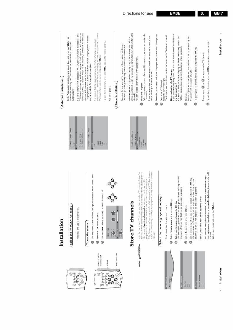
In t
he A
utom
atic
inst
alla
tion
men
u se
lect
Sta
rtan
d pr
ess
the
OK
key
toac
tivat
e th
e se
arch
ing.
All
TV
cha
nnel
s ar
e se
arch
ed fo
r an
d st
ored
auto
mat
ical
ly.
If a
cabl
e sy
stem
whi
ch b
road
cast
s A
CI (
Aut
omat
ic C
hann
el In
stal
latio
n) o
r a
TV
cha
nnel
tra
nsm
ittin
g a
tele
text
pag
e w
ith t
he fr
eque
ncie
s an
d pr
ogra
mm
ena
mes
of a
ll th
e T
V c
hann
els
whi
ch c
an b
e re
ceiv
ed,i
s de
tect
ed,t
he s
earc
h is
stop
ped
and
a pr
ogra
mm
e lis
t ap
pear
s.T
he p
rogr
amm
e lis
t is
aut
omat
ical
ly fi
lled
with
all
the
prog
ram
me
num
bers
and
nam
es o
f the
TV
cha
nnel
s tr
ansm
itted
.
It is
poss
ible
tha
t th
e ca
ble
com
pany
or
the
TV c
hann
el d
ispla
ys a
bro
adca
stse
lect
ion
men
u.La
yout
and
item
s ar
e de
fined
by
the
cabl
e co
mpa
ny o
r th
e TV
cha
nnel
.M
ake
your
cho
ice
with
the
cur
sor
and
pres
s th
e O
Kke
y.
To e
xit
from
the
men
u pr
ess
the
ME
NU
key
on t
he r
emot
e co
ntro
l.
Go
on t
o pa
ge 6
.
5In
stal
lati
on
Man
ual
inst
alla
tio
n
Au
tom
atic
inst
alla
tio
n
Automatic installation
Start
Stop
TV is searching
One moment please ...
JStop
K
Automatic installation
Start
Stop 1 BBC1
2 BBC2
3 CNN
....
....
JStart
K
Manual installation
(Selection mode)
System
Programme no.
Search
Fine tune
Store
JSystem
K
4In
stal
lati
on
Sto
re T
V c
han
nel
s
Firs
t,se
lect
you
r la
ngua
ge a
nd c
ount
ry.
&Se
lect
Men
u l
angu
age
and
pres
s th
e O
Kke
y.
éSe
lect
you
r la
ngua
ge a
nd p
ress
the
OK
key.
Use
the
cur
sor
up/d
own
to s
crol
l thr
ough
the
list
and
to
brin
g up
oth
erla
ngua
ges
whi
ch a
re n
ot d
ispl
ayed
on
the
scre
en a
t pr
esen
t.
“Se
lect
Co
un
try
and
pres
s th
e O
Kke
y.
‘Se
lect
the
cou
ntry
whe
re y
ou a
re n
ow lo
cate
d an
d pr
ess
the
OK
key.
Use
the
cur
sor
up/d
own
to s
crol
l thr
ough
the
list
and
bri
ng u
p ot
her
coun
trie
s w
hich
are
not
dis
play
ed o
n th
e sc
reen
at
pres
ent.
Sele
ct O
ther
whe
n no
ne o
f the
cou
ntri
es a
pplie
s.
You
can
now
sea
rch
for
and
stor
e th
e T
V c
hann
els
in t
wo
diffe
rent
way
s:us
ing
auto
mat
ic i
nst
alla
tio
nor
man
ual
in
stal
lati
on
(tun
ing-
in c
hann
el b
ych
anne
l).Se
lect
you
r ch
oice
and
pre
ss t
he O
Kke
y.
Sel
ect
the
men
u la
ngu
age
and
co
un
try
MENU
TITLE
Menu language
JINSTALLATION
MENU
TITLE
United Kingdom
....
....
JCountry
MENU
TITLE
English
....
....
JMenu language
Pres
s U
and
hat
the
sam
e tim
e.
Inst
alla
tio
n
Sel
ect
the
INS
TA
LL
AT
ION
men
u
&U
se t
he c
urso
r in
the
up/
dow
n,le
ft/r
ight
dir
ectio
ns t
o se
lect
a m
enu
item
.
éPr
ess
the
OK
key
to a
ctiv
ate.
“U
se t
he M
EN
Uke
y to
ret
urn
or t
o sw
itch
the
men
u of
f.
To u
se t
he
men
us
B
®Ò
‡π
†
fh
U
æ
MEN
U
b
OK
INST
AN
TQ
yÚ
VP
21
3
54
6
87
9B
®Ò
‡π
†
¬fh
U
æ
MEN
U
b
OK
◊
INST
AN
TQ
yÚ
sele
ct m
enu
item
retu
rn o
r sw
itch
mai
n m
enu
off
activ
ate
MENU
TITLE
Subject 1
Subject 2
Subject 3
JSubject 4
Subject 5
Subject 6
JSubject 4
L
M
Afte
r th
e ne
w o
r ex
tra T
V ch
anne
ls ha
ve b
een
stor
ed,t
he T
V au
tom
atic
ally
trans
fers
thos
e TV
cha
nnel
s to
the
vid
eo r
ecor
der
if it
is eq
uipp
ed w
ith t
he E
asyL
ink
func
tion.
The
mes
sage
Eas
yLin
k :d
ownl
oadi
ng .
.....
appe
ars
on t
he s
cree
n.Th
epr
ogra
mm
e lis
t of
the
vid
eo r
ecor
der
is no
w t
he s
ame
as t
he o
ne o
f th
e TV
.If
the
TV is
con
nect
ed t
o a
video
rec
orde
r w
hich
sup
port
s th
e N
EXTV
IEW
Link
fun
ctio
n,th
e TV
also
aut
omat
ical
ly tra
nsfe
rs t
he la
ngua
ge a
nd c
ount
ry s
elec
tions
to
the
video
reco
rder
.

Directions for useGB 8 EM3E3.
7In
stal
lati
on
The
Set
up m
enu
allo
ws
you
to a
djus
t in
itial
set
tings
,i.e
.tho
se w
hich
are
not
rela
ted
to t
he in
stal
latio
n of
the
TV
cha
nnel
s.T
he S
etup
men
u co
ntai
ns it
ems
that
con
trol
the
set
tings
of t
he T
V’s
func
tions
,fe
atur
es,s
ervi
ces
and
peri
pher
als
you
may
hav
e co
nnec
ted.
&U
se t
he c
urso
r in
the
up/
dow
n,le
ft/r
ight
dir
ectio
ns t
o se
lect
the
men
u ite
m.
éU
se t
he O
Kke
y to
act
ivat
e.
“U
se t
he M
EN
Uke
y to
ret
urn
or s
witc
h m
enu
off.
Dig
ital
so
urc
es
(for
futu
re u
se)
Def
ine
Dec
od
er/D
escr
ambl
er p
rogr
amm
e nu
mb
ers
If a
deco
der
or a
des
cram
bler
is c
onne
cted
,see
p.2
2 yo
u ca
n de
fine
one
orm
ore
prog
ram
me
num
bers
as
deco
der
prog
ram
me
num
bers
.
Pres
s th
e cu
rsor
left
/rig
ht t
o se
lect
the
inpu
t us
ed t
o co
nnec
t to
you
rde
code
r O
ff,E
XT
1or
EX
T2.
Sele
ct O
ffif
you
do n
ot w
ant
the
sele
cted
pro
gram
me
num
ber
bein
gac
tivat
ed a
s a
deco
der
prog
ram
me
num
ber.
Sele
ct E
XT
2w
hen
the
deco
der
is co
nnec
ted
to y
our
Easy
Link
vid
eo r
ecor
der.
Whe
n se
lect
ing
the
deco
der,
the
mes
sage
Eas
yLin
k:do
wnl
oadi
ng p
rese
ts...
.ap
pear
s on
the
scr
een.
Pic
ture
tilt
Se
lect
Pic
ture
tilt
with
the
cur
sor
up/d
own.
Kee
p th
e cu
rsor
left
/rig
ht p
ress
ed t
o ad
just
the
rot
atio
n of
the
pic
ture
.
Info
rmat
ion
lin
eSe
lect
On
and
afte
r th
e se
lect
ion
of a
TV
pro
gram
me
or a
fter
pre
ssin
g th
ei
key
on t
he r
emot
e co
ntro
l,a
TV
cha
nnel
whi
ch b
road
cast
s te
lete
xt m
aytr
ansm
it th
e na
me
of t
he T
V c
hann
el,t
he p
rogr
amm
e na
me
or a
noth
erm
essa
ge.T
his
is d
ispl
ayed
on
scre
en n
ext
to in
form
atio
n ab
out
soun
d an
dpi
ctur
e fo
rmat
.W
hen
sele
cted
Off,o
nly
soun
d an
d pi
ctur
e fo
rmat
info
rmat
ion
is d
ispl
ayed
afte
r th
e se
lect
ion
of a
TV
cha
nnel
or
afte
r pr
essi
ng t
he i
key.
Fac
tory
set
tin
gsSe
lect
Fac
tory
set
tin
gsan
d pr
ess
the
OK
key
to r
esto
re p
ictu
re a
nd s
ound
sett
ings
,pre
defin
ed in
the
fact
ory.
Au
to f
orm
atSe
lect
ing
Yes
caus
es t
he s
cree
n to
aut
omat
ical
ly fi
ll as
muc
h of
the
pic
ture
as
poss
ible
whe
n T
V p
rogr
amm
es a
re n
ot c
arry
ing
spec
ial s
igna
ls d
etec
ting
the
corr
ect
scre
en fo
rmat
.W
ith t
he q
key
on t
he r
emot
e co
ntro
l you
can
stil
l sel
ect
othe
r pi
ctur
efo
rmat
s.Se
e p.
10.
Inst
all T
V S
etu
pINSTALLATION
Menu language
Country
Automatic installation
Manual installation
Give name
Reshuffle
Favourite programmes
SETUP
JSETUP
Decoder/Descrambler
Programme
Decoder status
JProgramme
SETUP
Digital Sources
Decoder/Descrambler
Picture tilt
Information line
Factory settings
Auto format
yes/no
Auto Surround
INSTALLATION
JDecoder/Descrambler
6In
stal
lati
on
Giv
e n
ame
It is
pos
sibl
e to
cha
nge
the
nam
e st
ored
in t
he m
emor
y or
to
assi
gn a
nam
eto
a T
V c
hann
el w
hich
has
not
yet
bee
n en
tere
d.A
nam
e w
ith u
p to
5 le
tter
sor
num
bers
can
be
give
n to
the
pro
gram
me
num
bers
0 t
o 99
.For
exa
mpl
eSU
PER
,BBC
1,...
Betw
een
99 a
nd 0
you
can
als
o na
me
any
peri
pher
als
that
are
conn
ecte
d to
a e
uroc
onne
ctor
.
&Se
lect
Giv
e n
ame
in t
he I
NS
TA
LL
AT
ION
men
u an
d pr
ess
the
OK
key.
éSe
lect
the
pro
gram
me
num
ber.
“Pr
ess
the
OK
key.
‘Se
lect
the
cha
ract
er w
ith t
he c
urso
r up
/dow
n.
(Se
lect
the
follo
win
g po
sitio
n w
ith t
he c
urso
r ri
ght.
§Se
lect
the
follo
win
g ch
arac
ter.
èPr
ess
the
OK
key
whe
n fin
ishe
d.
!Pr
ess
the
ME
NU
key
to r
etur
n to
the
IN
ST
AL
LA
TIO
Nm
enu.
Spac
e,nu
mbe
rs a
nd o
ther
spe
cial
cha
ract
ers
are
loca
ted
betw
een
Z a
nd A
.
Acc
ordi
ng t
o yo
ur p
refe
renc
e yo
u ca
n c
hang
e th
e or
der
of t
he s
tore
d T
Vch
anne
ls.
&Se
lect
Res
hu
ffle
in t
he I
NS
TA
LL
AT
ION
men
u an
d pr
ess
the
OK
key.
éSe
lect
the
pro
gram
me
num
ber
you
wan
t to
exc
hang
e.
“Pr
ess
the
OK
key.
‘Se
lect
the
new
num
ber
you
wan
t to
exc
hang
e it
with
.
(Pr
ess
the
OK
key.
Rep
eat
the
oper
atio
n un
til a
ll T
V c
hann
els
are
allo
cate
d as
you
like
.
§Pr
ess
the
ME
NU
key
to r
etur
n to
the
IN
ST
AL
LA
TIO
Nm
enu.
Res
hu
ffle
th
e p
rogr
amm
e lis
t
Aft
er le
avin
g th
e in
stal
latio
n yo
u ca
n br
owse
thr
ough
the
TV
cha
nnel
s by
pres
sing
the
- P
+ke
y.O
nly
thos
e T
V c
hann
els
whi
ch a
re in
the
favo
urite
list
will
be
disp
laye
d.N
on-f
avou
rite
TV
cha
nnel
s ca
n st
ill b
e se
lect
ed w
ith t
he d
igit
keys
.By
defa
ult
all s
tore
d ch
anne
ls a
re a
dded
to
the
favo
urite
list
.
&Se
lect
Fav
ou
rite
pro
gram
mes
in t
he I
NS
TA
LL
AT
ION
men
u an
d pr
ess
the
OK
key.
éSe
lect
you
r fa
vour
ite p
rogr
amm
e nu
mbe
r.
“Se
lect
Yes
or N
ow
ith t
he c
urso
r le
ft/r
ight
.
‘R
epea
t fo
r ev
ery
TV
cha
nnel
you
wan
t to
mak
e a
favo
urite
or
ano
n-fa
vour
ite T
V c
hann
el.
(Pr
ess
the
ME
NU
key
to r
etur
n to
the
IN
ST
AL
LA
TIO
Nm
enu.
In o
rder
for
NEX
TVIE
Wto
fun
ctio
n pr
oper
ly,th
e fir
st T
V ch
anne
l fro
m t
he fa
vour
ite li
stsh
ould
also
bro
adca
st t
he c
orre
ct lo
cal d
ate
and
time
via t
elet
ext.
Sel
ect
Fav
ou
rite
TV
ch
ann
els
INSTALLATION
Menu language
Country
Automatic installation
Manual installation
Give name
Reshuffle
Favourite programmes
SETUP
JGive name
Give name
EXT1
EXT2
EXT3
FRONT
0 1 BBC1
2 BBC2
3 ....
4 ....
5 ....
J0
Reshuffle
EXT1
EXT2
EXT3
FRONT
0
1 CNN
2 BBC2
3 ....
4 ....
5 ....
J1 CNN
Favourite programmes
0 ...
No1 ...
Yes
2 ...
No3 ....
No4 ....
Yes
5 ....
J2 ...
Yes

Directions for use GB 9EM3E 3.
9U
se o
f th
e re
mo
te c
on
tro
l
Op
erat
ion
Use
of
the
rem
ote
co
ntr
ol
yÚ
VP
SMA
RT
ACT
IVE
CON
TRO
L
Ma
w
h
qbS
X
21
3
54
6
87
9
0
B
®Ò
‡π
†
¬
i0
fh
U
æ
MEN
U
b
OK
◊
INST
AN
TQ
BS
tan
dby
The
set
is s
witc
hed
off.T
o sw
itch
the
TV
on
agai
n,pr
ess
- P
+or
the
dig
it ke
ys.
If yo
ur E
asyL
ink
vide
o re
cord
er h
as t
hesy
stem
sta
ndby
func
tion
and
you
pres
s th
est
andb
y ke
y fo
r 3
seco
nds,
both
the
TV
and
vide
o re
cord
er a
re s
witc
hed
to s
tand
by.
Your
TV
cons
umes
ene
rgy
in t
he s
tand
by m
ode.
Ener
gy c
onsu
mpt
ion
cont
ribut
es t
o ai
r an
d w
ater
pollu
tion.
We
advis
e to
sw
itch
off
your
TV
over
nigh
t in
stea
d of
leav
ing
it on
sta
ndby
.You
save
ene
rgy.
®Ò
‡π
†V
ideo
rec
ord
er s
ee p
.24
®In
stan
tre
cord
If yo
ur v
ideo
rec
orde
r ha
s th
e Ea
syLi
nkfu
nctio
n th
e IN
ST
AN
T®
key
for
reco
rd c
anbe
ope
rate
d in
the
TV
mod
e.
æN
EX
TV
IEW
/TX
T g
uid
e on
/off
se
e p.
15
ME
NU
Mai
n m
enu
o
n/of
f se
e p.
11
OK
Pres
s th
is k
ey t
o ac
tivat
e yo
ur c
hoic
e,w
hen
in t
he m
enus
.Q
Su
rro
un
d m
od
es
Incr
edib
le S
urr
ou
nd
With
ste
reo
tran
smis
sion
,and
whe
nIn
cred
ible
Su
rro
un
d is
sel
ecte
d,it
seem
s as
thou
gh t
he lo
udsp
eake
rs a
re s
prea
d fu
rthe
rap
art
from
one
ano
ther
.
Vir
tual
Do
lby
Su
rro
un
d
(opt
imal
with
Dol
by S
urro
und
signa
ls)V
irtu
al D
olby
Su
rrou
nd e
nabl
es y
ou t
oex
peri
ence
the
effe
ct o
f Dol
by S
urro
und
Pro
Logi
c,re
prod
ucin
g a
rear
sou
nd e
ffect
.Se
e So
und
men
u,V
irtu
al D
olby
effe
ct,p
.12.
iS
cree
n i
nfo
rmat
ion
Pres
s fo
r 5
seco
nds
to a
ctiv
ate/
de-a
ctiv
ate
the
exte
nded
or
redu
ced
disp
lay
of T
Vch
anne
l and
pro
gram
me
info
rmat
ion
on t
hesc
reen
.
Pres
s br
iefly
to
disp
lay
info
rmat
ion
abou
t th
ese
lect
ed T
V c
hann
el a
nd p
rogr
amm
e,th
eso
und
rece
ptio
n,pi
ctur
e se
ttin
gs a
nd t
here
mai
ning
tim
e se
t w
ith t
he s
leep
timer
.
0/9
Dig
it k
eys
To s
elec
t a
TV
cha
nnel
.Fo
r a
two
digi
t pr
ogra
mm
e nu
mbe
r,en
ter
the
seco
nd d
igit
with
in 2
seco
nds.
To s
witc
h im
med
iate
ly t
o a
sele
cted
one
dig
it T
V c
hann
el,k
eep
the
digi
tke
y pr
esse
d a
bit
long
er.
0P
revi
ou
s p
rogr
amm
eT
he p
revi
ousl
y se
lect
ed T
V c
hann
el is
dis
play
ed.
The
◊in
dica
tion
is o
nly
vide
o re
cord
er.
Use
of
the
rem
ote
co
ntr
ol
bTe
lete
xt
on/
off
see
p.19
fh
T
elet
ext
fun
ctio
ns
se
e p.
20
hZ
oo
mPr
ess
the
ZO
OM
hke
y re
peat
edly
to
sele
cton
e of
the
zoo
m m
agni
ficat
ions
(x1
,x4,
x9,
x16)
.Add
ition
ally
you
can
shi
ft t
he s
elec
ted
zoom
win
dow
ove
r th
e sc
reen
with
the
curs
or.
Pres
s i
to a
ctiv
ate/
de-a
ctiv
ate
the
cont
inuo
us d
ispl
ay o
f the
zoo
m m
agni
ficat
ion.
The
zoo
m w
indo
w is
res
et a
fter
:sel
ectin
gan
othe
r T
V c
hann
el,a
noth
er p
ictu
re fo
rmat
or w
hen
anot
her
pict
ure
form
at is
sel
ecte
dau
tom
atic
ally
.Z
oom
ing
is di
sabl
ed in
Dua
l scr
een
mod
e.
UT
ime
dis
pla
yT
he t
ime,
dow
nloa
ded
from
the
TV
cha
nnel
(with
tel
etex
t) s
tore
d on
pro
gram
me
num
ber
1 or
the
low
est
favo
urite
pro
gram
me
num
ber,
is d
ispl
ayed
on
the
scre
en.
This
func
tion
is no
t av
aila
ble
whe
n co
ntin
uous
subt
itles
hav
e be
en s
witc
hed
on.
VV
olu
me
Pres
s +
or
- to
adj
ust
the
volu
me.
¬
Mu
te
Tem
pora
rily
inte
rrup
t th
e so
und
or r
esto
re it.
PP
rogr
amm
e se
lect
ion
To b
row
se t
hrou
gh t
he T
V c
hann
els
activ
ated
in t
heFa
vour
ite P
rogr
amm
e m
enu.
8In
stal
lati
on
Au
to S
urr
ou
nd
Som
etim
es t
he b
road
cast
er t
rans
mits
spe
cial
sig
nals
for
Surr
ound
Sou
nden
code
d pr
ogra
mm
es.I
n th
at c
ase,
the
TV
aut
omat
ical
ly s
witc
hes
to t
hebe
st S
urro
und
Soun
d m
ode
whe
n A
uto
Surr
ound
is s
witc
hed
on.
Vir
tual
Dol
by*
Surr
ound
will
be
repr
oduc
ed,s
ee p
.9.
Ove
rrul
ing
this
sur
roun
d m
ode
rem
ains
pos
sibl
e.
Inst
alla
tio
nSe
lect
In
stal
lati
on
and
pres
s th
e O
Kke
y to
ret
urn
imm
edia
tely
to
the
INS
TA
LL
AT
ION
men
u.
‘To
exi
t fr
om t
he m
enu
pres
s th
e M
EN
Uke
y re
peat
edly
.
SETUP
Digital Sources
Decoder/Descrambler
Picture tilt
Information line
Factory settings
Auto format
yes/no
Auto Surround
INSTALLATION
JAuto Surround
‘Dol
by’ ‘
Pro
Logi
c’ a
nd t
he d
oubl
e-D
sym
bol
are
trad
emar
ks o
f Dol
by L
abor
ator
ies
Lice
nsin
g C
orpo
ratio
n.M
anuf
actu
red
unde
r lic
ense
from
Dol
by L
abor
ator
ies
Lice
nsin
g C
orpo
ratio
n.

Directions for useGB 10 EM3E3.
11U
se o
f th
e m
enu
s
&Pr
ess
the
ME
NU
key
to d
ispl
ay/c
ance
l the
MA
IN M
EN
U.
éU
se t
he c
urso
r in
the
up/
dow
n di
rect
ions
to
sele
ct t
he P
ICT
UR
E,S
OU
ND
orF
EA
TU
RE
Sm
enu
or t
o se
lect
the
PR
OG
RA
MM
ES.
“Pr
ess
the
curs
or r
ight
to
activ
ate
the
sele
cted
men
u.
‘U
se t
he c
urso
r in
the
up/
dow
n,le
ft/r
ight
dir
ectio
ns t
o se
lect
the
men
u ite
m.
(U
se t
he O
Kke
y to
act
ivat
e.
§Pr
ess
the
ME
NU
key
repe
ated
ly t
o re
turn
or
to s
witc
h th
e m
enu
off.
Pic
ture
men
u
If an
NTS
C pe
riphe
ral i
s co
nnec
ted
to o
ne o
f th
e eu
roco
nnec
tors
,the
opt
ion
Hue
also
app
ears
.
Tin
tSe
lect
the
col
our
tem
pera
ture
:No
rmal
,War
mor
Co
ol.
Dig
ital
op
tio
ns
Alth
ough
Nat
ural
Mot
ion
is t
he m
ost
idea
l set
ting,
it m
ay b
e pr
efer
able
to
switc
h ba
ck t
o D
igita
l Sca
n an
d/or
100
Hz.
To m
ake
all t
he 3
dig
ital o
ptio
ns a
vaila
ble
at t
he s
ame
time
and
sele
ctab
le,f
irst
sele
ct a
4:3
pic
ture
form
at.
• 10
0 H
z=
100
Hz
only
(Fi
eld
flick
er r
educ
tion)
• D
ig.S
can
= 1
00 H
z +
Dig
.Sca
n (F
ield
and
line
flic
ker
redu
ctio
n)•
Nat
ura
l M
oti
on
= 1
00 H
z +
Dig
.Sca
n +
Nat
ural
Mot
ion
(Fie
ld a
nd li
nefli
cker
red
uctio
n an
d sm
ooth
mov
emen
t re
prod
uctio
n)•
Do
ubl
e lin
es=
pro
vide
s fo
r a
doub
ling
of v
ertic
al r
esol
utio
n w
hich
add
s as
toni
shin
g sh
arpn
ess
and
a to
tal a
bsen
ce o
f vis
ible
pic
ture
line
s.M
otio
n co
mpe
nsat
ion
redu
ces
jitte
r an
d of
fers
sm
ooth
,yet
sha
rp m
otio
n re
prod
uctio
n.
Not
e:if
the
men
u ite
m D
igita
l opt
ions
is n
ot p
rese
nt,f
irst
sele
ct a
4:3
pic
ture
form
atw
ith t
he q
key.
Dyn
amic
Co
ntr
ast
To m
ake
the
cont
rast
in t
he d
arke
r an
d th
e br
ight
er p
ictu
re a
reas
mor
eno
ticea
ble,
sele
ct t
he M
edse
ttin
g.In
cer
tain
cir
cum
stan
ces
it m
ay b
e pr
efer
red
to s
elec
t M
in,M
axor
Off.
The
mod
ified
adj
ustm
ents
for
Con
tras
t,Br
ight
ness
,Col
our,
Shar
pnes
s,T
int,
Dig
ital S
can
and
Dyn
amic
Con
tras
t ar
e au
tom
atic
ally
sto
red
for
all T
Vch
anne
ls.
Sele
ct F
acto
ry s
etti
ngs
in t
he S
etup
men
u to
res
tore
the
pre
defin
ed fa
ctor
yse
ttin
gs,s
ee p
.7.
Use
of
the
men
us
PICTURE
Contrast
Brightness
Colour
Sharpness
Tint
Digital options
Dynamic Contrast
JContrast
L
M
MAIN
MENU
Contrast
SOUND
FEATURES
PROGRAMMES
JPICTURE
curs
or t
o se
lect
adju
stm
ents
retu
rn o
r sw
itch
mai
n m
enu
on/o
ff
VP
21
3B
®Ò
‡π
†
¬fh
U
æ
MEN
U
b
OK
INST
AN
TQ
yÚ
OK
key
to a
ctiv
ate
10U
se o
f th
e re
mo
te c
on
tro
l
yÚ
VP
SMA
RT
ACT
IVE
CON
TRO
L
Ma
w
h
qbS
X
21
3
54
6
87
9
0
B
®Ò
‡π
†
¬
i0
fh
U
æ
MEN
U
b
OK
◊
INST
AN
TQ
hA
ctiv
e co
ntr
ol
Act
ive
cont
rol i
s a
pro-
activ
e an
d au
tom
atic
sys
tem
.The
TV
con
tinuo
usly
mea
sure
s an
d co
rrec
ts a
ll in
com
ing
sign
als
in o
rder
to
prov
ide
the
best
pict
ure
poss
ible
.Pr
ess
the
hke
y t
o se
lect
the
Act
ive
Con
trol
val
ues
Off
or O
n.O
ffSh
arpn
ess
and
Dyn
amic
Con
tras
t ar
e co
ntro
lled
auto
mat
ical
lyO
nSh
arpn
ess,
Dyn
amic
Con
tras
t an
d N
oise
Red
uctio
n ar
e co
ntro
lled
auto
mat
ical
ly.
Pres
s th
e cu
rsor
in t
he u
p/do
wn
dire
ctio
ns w
hile
the
sel
ecte
d A
ctiv
eC
ontr
ol s
ettin
g in
form
atio
n is
on
top
of t
he s
cree
n.T
he A
ctiv
e C
ontr
ol m
enu
appe
ars.
The
pic
ture
set
tings
are
bei
ng a
dapt
ed c
ontin
uous
ly a
nd a
utom
atic
ally
.T
he m
enu
item
s ca
nnot
be
sele
cted
.Pr
ess
the
curs
or in
the
up/
dow
n di
rect
ions
aga
in t
o sw
itch
off t
he m
enu.
wS
elec
t p
erip
her
als
Pres
s th
is k
ey r
epea
tedl
y to
sel
ect
EX
T1,
EX
T2,
EX
T3
or F
RO
NT
,acc
ordi
ng t
o w
here
you
conn
ecte
d th
e pe
riph
eral
s (p
.24)
.
Sm
art
Key
sTo
sel
ect
pred
efin
ed p
ictu
re a
nd s
ound
sett
ings
.
M
Sm
art
So
un
dEa
ch t
ime
it is
pre
ssed
,a d
iffer
ent
soun
dse
ttin
g is
sel
ecte
d,co
rres
pond
ing
with
spec
ific
fact
ory
sett
ings
of t
he e
qual
izer
.
aS
mar
t P
ictu
reEa
ch t
ime
it is
pre
ssed
,a d
iffer
ent
pict
ure
sett
ing
is s
elec
ted,
corr
espo
ndin
g w
ithsp
ecifi
c fa
ctor
y se
ttin
gs o
f Con
tras
t,C
olou
r,Sh
arpn
ess
and
Dyn
amic
Con
tras
t.
Per
son
alre
fers
to
the
pers
onal
pre
fere
nce
sett
ings
of p
ictu
re a
nd s
ound
sel
ecte
d in
the
pict
ure
and
soun
d m
enu.
Rem
ark:
the
mom
ent
you
are
in a
pre
defin
edsm
art
soun
d or
pic
ture
set
ting
and
you
mod
ify a
sett
ing
in t
he p
ictu
re o
r so
und
men
u,al
l val
ues
ofth
e m
enu
will
over
writ
e th
e pr
evio
usly
mad
ese
ttin
gs.
XB
ilin
gual
ch
oic
e an
d
sou
nd
mo
de
sele
ctio
n
Pres
s th
is k
ey
• to
sw
itch
from
Ste
reo
to M
on
oso
und,
inca
se o
f ste
reo
tran
smis
sion
,or
from
Nic
am S
tere
oto
Nic
am a
vaila
ble,
in c
ase
of d
igita
l tra
nsm
issi
on;
• to
cho
ose
betw
een
lang
uage
Y(D
ual Y
) or
lang
uage
Z(D
ual Z
),in
cas
e of
bili
ngua
ltr
ansm
issi
on.T
he s
ettin
g is
sep
arat
ely
stor
ed fo
r ea
ch T
V c
hann
el.
SF
reez
eTo
act
ivat
e/de
-act
ivat
e th
e fr
ozen
pic
ture
or
to h
old
a te
lete
xt p
age.
b
Dua
l scr
een,
see
p.14
qP
ictu
re f
orm
atPr
ess
this
key
rep
eate
dly
to s
elec
t an
othe
rpi
ctur
e fo
rmat
:4:3
,Mov
ie E
xpan
d 14
:9,
Mov
ie E
xpan
d 16
:9 w
ith o
r w
ithou
t su
btitl
ing,
Wid
e Sc
reen
,Sup
er Z
oom
or
Aut
omat
ic(w
hen
Aut
o fo
rmat
is s
et t
o Ye
s in
the
SE
TU
Pm
enu)
.A
utom
atic
mak
es t
he p
ictu
re t
o fil
l the
scre
en a
s m
uch
as p
ossi
ble.
Som
etim
es a
lso
vide
o re
cord
er p
rogr
amm
esca
rry
spec
ial s
igna
ls w
hich
will
aut
omat
ical
lysw
itch
the
TV
to
the
corr
ect
scre
en fo
rmat
.Au
to fo
rmat
is d
isabl
ed w
hen
in D
ual s
cree
n.W
hen
in M
ovie
Exp
and
14:9
or
16:9
or
Supe
r Z
oom
pic
ture
form
at y
ou c
an m
ake
subt
itles
vis
ible
with
the
cur
sor
up/d
own.

Directions for use GB 11EM3E 3.
13U
se o
f th
e m
enu
s
Feat
ure
s m
enu
&Pr
ess
the
ME
NU
key
to d
ispl
ay/c
ance
l the
MA
IN M
EN
U.
éU
se t
he c
urso
r in
the
up/
dow
n di
rect
ions
to
sele
ct t
he F
EA
TU
RE
Sm
enu.
“U
se t
he c
urso
r in
the
up/
dow
n,le
ft/r
ight
dir
ectio
ns t
o se
lect
the
men
u ite
m.
‘U
se t
he O
Kke
y t
o ac
tivat
e.
(Pr
ess
the
ME
NU
key
repe
ated
ly t
o re
turn
or
to s
witc
h th
e m
enu
off.
Sle
epti
mer
With
the
sle
eptim
er y
ou c
an s
et a
tim
e pe
riod
aft
er w
hich
the
TV
sho
uld
switc
h its
elf t
o st
andb
y.T
he c
ount
er r
uns
from
Off
up t
o 18
0 m
in.
One
min
ute
befo
re t
he T
V is
set
to
go t
o st
andb
y,th
e re
mai
ning
sec
onds
appe
ar o
n sc
reen
.N
ot v
isib
le in
dua
l scr
een
mod
e.Yo
u ca
n al
way
s sw
itch
off
your
set
ear
lier
or c
hang
e th
e se
t tim
e.
Ch
ild l
ock
If th
e ch
ild lo
ck is
on,
the
TV
can
onl
y be
sw
itche
d on
with
the
rem
ote
cont
rol.T
he P
- an
d +
key
s on
top
of t
he T
V c
anno
t be
use
d to
sel
ect
a T
Vch
anne
l.In
thi
s w
ay y
ou c
an p
reve
nt u
naut
hori
sed
use
of y
our
TV.
If th
e m
essa
geC
hild
lo
ck O
nap
pear
s,th
e ch
ild lo
ck m
ust
be s
witc
hed
off
befo
re y
ou c
an u
se t
he P
- an
d +
key
s on
top
of t
he T
V t
o se
lect
a T
Vch
anne
l.
Su
bti
tle
TV
cha
nnel
s w
ith t
elet
ext
ofte
n tr
ansm
it ce
rtai
n pr
ogra
mm
es w
ith s
ubtit
ling.
See
Tele
text
,Con
tinuo
us S
ubtit
les,
p.21
how
to
sele
ct t
he p
rope
r su
btitl
epa
ge fr
om t
he t
elet
ext
inde
x.Se
lect
Su
bti
tle
On
or O
ff.
Pres
s th
e M
EN
Uke
y to
sw
itch
off t
he F
eatu
res
men
u.
Pro
gram
me
list
&Pr
ess
the
ME
NU
key
to d
ispl
ay/c
ance
l the
MA
IN M
EN
U.
éSe
lect
PR
OG
RA
MM
ES
with
the
cur
sor
up/d
own.
“Pr
ess
the
curs
or r
ight
to
disp
lay
an o
verv
iew
of a
ll th
e T
V c
hann
els
inst
alle
d.
‘Pr
ess
the
curs
or u
p/do
wn
to r
un t
hrou
gh t
he li
st a
nd p
ress
OK
to s
elec
t th
ede
sire
d T
V c
hann
el.
(Pr
ess
the
ME
NU
key
to s
witc
h of
f the
Pro
gram
me
list.
Sleeptimer
Off
Child lock
Off
Subtitle
Off
JFEATURES
OK
key
to a
ctiv
ate
curs
or t
o se
lect
adju
stm
ents
retu
rn o
r sw
itch
mai
n m
enu
on/o
ff
VP
B
®Ò
‡π
†
¬fh
U
æ
MEN
U
b
OK
INST
AN
TQ
yÚ
12U
se o
f th
e m
enu
s
So
un
d m
enu
&Pr
ess
the
ME
NU
key
to d
ispl
ay/c
ance
l the
MA
IN M
EN
U.
éU
se t
he c
urso
r in
the
up/
dow
n di
rect
ions
to
sele
ct t
he S
OU
ND
men
u.
“U
se t
he c
urso
r in
the
up/
dow
n,le
ft/r
ight
dir
ectio
ns t
o se
lect
the
men
u ite
m.
‘U
se t
he O
Kke
y t
o ac
tivat
e.
(Pr
ess
the
ME
NU
key
repe
ated
ly t
o re
turn
or
to s
witc
h th
e m
enu
off.
The
mod
ified
adj
ustm
ents
for V
olum
e,Ba
lanc
e,an
d G
raph
ic e
qual
izer
are
auto
mat
ical
ly s
tore
d fo
r al
l TV
cha
nnel
s.Se
lect
Fac
tory
set
tin
gsin
the
Set
up m
enu
to r
esto
re t
he p
rede
fined
fact
ory
sett
ings
,see
p.7
.
Gra
ph
ic E
qu
aliz
erH
ere
you
can
sele
ct t
he p
refe
rred
sou
nd s
ettin
g w
hich
cor
resp
onds
with
the
pers
onal
sou
nd s
ettin
gs.
Hea
dp
ho
ne
volu
me
See
Con
nect
Per
iphe
ral E
quip
men
t,p.
23,f
or t
he c
onne
ctio
n of
the
head
phon
e.
AV
L
(Au
tom
atic
Vo
lum
e L
evel
ler)
AV
L au
tom
atic
ally
con
trol
s th
e vo
lum
e le
vel t
o av
oid
too
larg
e le
vel
diffe
renc
es,e
spec
ially
whe
n sw
itchi
ng t
o an
othe
r pr
ogra
mm
e or
dur
ing
com
mer
cial
bre
aks.
AV
L w
ill r
educ
e th
e dy
nam
ics
of t
he s
ound
.To
mai
ntai
n or
igin
al d
ynam
ics,
use
the
Del
ta v
olum
e fe
atur
e.
Del
ta v
olu
me
Her
e yo
u m
ay a
djus
t th
e vo
lum
e di
ffere
nces
of e
ach
sele
cted
TV
cha
nnel
or
exte
rnal
dev
ice
sepa
rate
ly.T
his
can
com
pens
ate
volu
me
diffe
renc
es b
etw
een
diffe
rent
bro
adca
ster
s.U
se t
he -
P +
keys
to
com
pare
to
the
volu
me
of o
ther
TV
cha
nnel
s or
exte
rnal
s.
Vir
tual
Do
lby
effe
ctV
irtu
al D
olby
ena
bles
you
to
expe
rien
ce t
he e
ffect
of D
olby
Sur
roun
d Pr
oLo
gic
with
out
the
need
of h
avin
g re
ar s
peak
ers
conn
ecte
d or
act
ivat
ed.
Sele
ct t
he le
vel o
f Vir
tual
Do
lby
effe
ctw
ith t
he c
urso
r le
ft/r
ight
.
OK
key
to a
ctiv
ate
curs
or t
o se
lect
adju
stm
ents
retu
rn o
r sw
itch
mai
n m
enu
on/o
ff
VP
B
®Ò
‡π
†
¬fh
U
æ
MEN
U
b
OK
INST
AN
TQ
yÚ
SOUND
Volume
Balance
Graphic Equalizer
Headphone Volume
AVL
Delta volume
Virtual Dolby effect
JVolume
L
M
Directions for useGB 12 EM3E3.
15N
EX
TV
IEW
Toda
y,m
ost
broa
dcas
ters
in E
urop
e,ar
e of
feri
ng t
elet
ext
page
s co
ntai
ning
th
eir
prog
ram
me
sche
dule
of t
oday
.The
se p
ages
can
be
requ
este
d by
sw
itchi
ngth
e T
V t
o Te
lete
xt G
uid
e.A
n in
crea
sing
num
ber
of b
road
cast
ers
are
offe
ring
an
exte
nded
pro
gram
me
guid
e se
rvic
e ca
lled
NE
XT
VIE
W.N
EXT
VIE
Wis
a n
ew w
ay o
f pre
sent
ing
prog
ram
me
sche
dule
s an
d of
fers
mor
e fe
atur
es t
han
com
mon
tel
etex
t.W
ith N
EXT
VIE
Wit
is p
ossi
ble
to s
how
for
inst
ance
all
the
mov
ies
com
ing
toni
ght.
Both
faci
litie
s ar
e in
tegr
ated
in t
his
TV
:NEX
TV
IEW
and
Tele
text
Pro
gram
me
Gui
de.I
f a T
V c
hann
el s
uppo
rts
NEX
TV
IEW
then
the
TV
will
aut
omat
ical
ly
pres
ent
the
NEX
TV
IEW
prog
ram
me
sche
dule
.If t
he T
V c
hann
el s
uppo
rts
just
te
lete
xt,t
hen
the
TV
will
sw
itch
auto
mat
ical
ly t
o Te
lete
xt G
uide
.Bo
th fa
cilit
ies
are
offe
ring
the
sam
e fu
nctio
ns:r
ecor
d,re
min
d an
d in
fo.
How
ever
in c
ase
of T
elet
ext
Gui
de t
he b
road
cast
er is
res
pons
ible
if t
hese
func
tions
are
pos
sibl
e.Yo
u ca
n se
arch
for
the
prog
ram
mes
you
wan
t to
wat
ch u
p to
7 d
ays
in a
dvan
ce.
It is
als
o po
ssib
le t
o se
arch
for
a pr
ogra
mm
e by
the
me,
e.g.
spor
t,m
ovie
,etc
.O
nce
a pr
ogra
mm
e ha
s be
en s
elec
ted
it ca
n be
tag
ged,
to r
emin
d yo
u,or
to
reco
rd o
n th
e vi
deo
reco
rder
aut
omat
ical
ly (
prov
ided
the
vid
eo r
ecor
der
iseq
uipp
ed w
ithN
EXT
VIE
WLi
nk L
evel
2.0
),on
ce,d
aily,
wee
kly
or s
erie
s.Te
lete
xt G
uide
/ NEX
TV
IEW
also
allo
ws
dire
ct a
cces
s to
det
aile
d in
form
atio
nab
out
prog
ram
mes
if p
rovi
ded
by t
he b
road
cast
er.
The
broa
dcas
ter
is re
spon
sible
for
the
cont
ents
of
the
info
rmat
ion.
The
TV is
res
pons
ible
for
the
capt
ure
of t
hat
info
rmat
ion
and
for
the
pres
enta
tion
toth
e us
er.
Use
of
the
Tele
text
Gu
ide/
NE
XT
VIE
Wm
enu
s
&Pr
ess
the
æke
y on
the
rem
ote
cont
rol t
o di
spla
y/ca
ncel
the
Tel
etex
t G
uide
/N
EXT
VIE
Wm
enu.
éU
se t
he c
urso
r in
the
up/
dow
n,le
ft/r
ight
dir
ectio
ns t
o se
lect
the
dat
e,C
HA
NN
EL
for
the
chan
nel g
uide
,TH
EM
Efo
r th
e th
eme
guid
e,O
VE
RV
IEW
for
an o
verv
iew
of a
ll th
e pr
ogra
mm
es w
hich
are
mar
ked
as r
emin
ders
or
for
reco
rdin
g,th
e pr
ogra
mm
e gu
ide
page
num
ber
or t
o en
ter
the
prog
ram
me
list.
NE
XT
VIE
W/ T
elet
ext
Gu
ide
Channel Overview
BBC1
BBC2
p.202
p 01 02 ...
π
BBC1
11.03
................
14.35
................ 226/3
17.50
................ 231
Record
Remind
Info
Tele
text
Gu
ide
NE
XT
VIE
W
Monday 9 Oct 18:03
Channel
Theme Overview
BBC1
NEXTVIEW
What’s on now
Preview
Themes
Ratings
Record
Remind
Info
“En
ter
the
prop
er p
rogr
amm
e gu
ide
page
num
ber
with
the
dig
it ke
ys o
r w
ith t
he –
P +
key
s.
‘Pr
ess
the
curs
or le
ft/r
ight
to
run
thro
ugh
the
subp
ages
.
(Se
lect
a p
rogr
amm
e w
ith t
he c
urso
r up
/dow
n.
§Pr
ess
one
of t
he c
olou
r ke
ys t
o se
lect
one
of t
heba
sic
func
tions
(if
avai
labl
e);r
eco
rd,r
emin
d,i
nfo
.Se
e Ba
sic
func
tions
furt
her
on.
èPr
ess
the
OK
key
to r
etur
n to
the
hea
der
area
agai
n.
“Se
lect
a p
rogr
amm
e w
ith t
he c
urso
r up
/dow
n.
‘Pr
ess
one
of t
he c
olou
r ke
ys t
o se
lect
one
of t
heba
sic
func
tions
(if
avai
labl
e);r
eco
rd,r
emin
d,i
nfo
.Se
e Ba
sic
func
tions
furt
her
on.
(Pr
ess
the
OK
key
to r
etur
n to
the
hea
der
area
agai
n.
curs
or t
o se
lect
adju
stm
ents
VP
21
3
54
6
87
9
0
B
¬fh
U
æ
MEN
U
b
OK
◊
INST
AN
TQ
æ MEN
U
yÚ
NEX
TV
IEW
sele
ctio
n
14D
ual
Scr
een
&Pr
ess
the
bke
y to
sw
itch
on D
ual S
cree
n.T
he T
V s
cree
n is
div
ided
into
2 p
arts
:-
the
left
sid
e fo
r th
e no
rmal
mai
n pi
ctur
e,-
the
righ
t si
de fo
r te
lete
xt b
road
cast
by
the
sele
cted
TV
cha
nnel
or
for
NEX
TV
IEW
/Tel
etex
t G
uide
.To
ope
rate
NEX
TV
IEW
/Tel
etex
t G
uide
,see
p.1
5.To
ope
rate
tel
etex
t,se
e p.
19.
If D
ual S
cree
n is
Off,
the
pict
ure,
tele
text
or
NEX
TVIE
W/T
elet
ext
Gui
de a
re d
ispla
yed
full
scre
en.
éPr
ess
the
qke
y to
sel
ect
a ve
rtic
al s
quee
zed
or a
non
ver
tical
squ
eeze
dpi
ctur
e si
ze
“Pr
ess
+ P
-to
run
thr
ough
the
tel
etex
t pa
ges.
‘W
hen
in T
elet
ext
Dua
l Scr
een,
pres
s th
e b
key
to r
etur
n to
a fu
ll pi
ctur
esc
reen
or
pres
s th
e b
key
to
retu
rn t
o a
full
Tele
text
scr
een.
(W
hen
in N
EXT
VIE
W/T
elet
ext
Gui
de D
ual S
cree
n,pr
ess
the
æke
y to
ret
urn
to a
full
pict
ure
scre
en o
r pr
ess
the
bke
y to
ret
urn
to a
full
NEX
TV
IEW
/Tel
etex
t G
uide
scr
een.
VP
SMA
RT
ACT
IVE
CON
TRO
L
Ma
w
h
bS
X
21
3
54
6
87
9
0
B
®Ò
‡π
†
¬
i0
fh
U
æ
MEN
U
b
OK
◊ q
INST
AN
TQ
b q
æ
b
yÚ
Du
al S
cree
n

Directions for use GB 13EM3E 3.
17N
EX
TV
IEW
Bas
ic f
un
ctio
ns
The
func
tions
Rec
ord,
Rem
ind
and
Info
can
be
activ
ated
with
the
corr
espo
ndin
g co
lour
key
s on
the
rem
ote
cont
rol.
If th
e fu
nctio
n is
not
ava
ilabl
e,th
en t
he t
ext
is s
how
n at
red
uced
bri
ghtn
ess.
Sele
ct a
pro
gram
me
with
the
cur
sor
up/d
own.
Rec
ord
Ro
r R
emin
d !
&Pr
ess
the
red
colo
ur k
ey t
o ac
tivat
e R
eco
rdor
the
gre
en c
olou
r ke
y to
activ
ate
Rem
ind.
If th
e pr
ogra
mm
e nu
mbe
r of
the
bro
adca
ster
is n
ot y
et k
now
n,a
mes
sage
app
ears
with
the
req
uest
to
inpu
t th
e co
rrec
t pr
ogra
mm
e nu
mbe
r w
ith t
he c
urso
r le
ft/rig
htan
d pr
ess
OK.
A s
mal
l men
u po
ps u
p in
whi
ch y
ou c
an c
hoos
e th
e in
terv
al:o
nce,
daily
or
wee
kly,
or c
lear
an
earl
ier
mad
e re
cord
or
rem
ind
sett
ing.
The
def
ault
inte
rval
is s
et t
o O
nce
.If a
pro
gram
me
is a
n ep
isod
e of
a s
erie
s,it
is id
entif
ied
by t
hesy
stem
and
the
opt
ions
dai
lyan
d w
eekl
yar
e re
plac
ed b
y th
e op
tion
seri
es.I
nth
is c
ase
the
syst
em id
entif
ies
whe
n th
e ne
xt e
piso
de o
f the
ser
ies
will
be
broa
dcas
t.T
his
is n
ot p
ossi
ble
in t
he T
elet
ext
guid
e.
éU
se t
he c
urso
r in
the
left
/rig
ht d
irec
tions
to
sele
ct t
he in
terv
al.
The
col
our
of t
he t
ag r
efer
s to
the
inte
rval
.
“Pr
ess
the
OK
key.
Whe
n R
eco
rd R
is a
ctiv
ated
:S
tori
ng
is d
ispl
ayed
to
indi
cate
the
vid
eo r
ecor
der
is p
rogr
amm
ed.
Whe
n R
emin
d !
is a
ctiv
ated
:-
a m
essa
ge w
ill b
e di
spla
yed
the
mom
ent
the
tagg
ed p
rogr
amm
e w
ith !
star
ts,w
hen
wat
chin
g th
e T
V la
ter
on.
-th
e T
V s
witc
hes
on t
he m
omen
t th
e ta
gged
pro
gram
me
with
!st
arts
,w
hen
the
TV
is in
sta
ndby
.N
ote:
Reco
rdin
gs a
nd r
emin
ders
are
not
pos
sible
whe
n th
e br
oadc
aste
r do
es n
ottra
nsm
it da
tes
and
times
of
the
prog
ram
mes
.Th
e m
essa
ge N
o T
V p
rogr
amm
ing
pos
sibl
eap
pear
s.M
ake
sure
you
are
on
the
TV p
rogr
amm
ing
page
.
Info
&
Pres
s th
e ye
llow
col
our
key
to a
ctiv
ate
Info
.A
dver
tisem
ents
or
info
rmat
ion
rela
ting
to t
he s
elec
ted
prog
ram
me
are
disp
laye
d.In
som
e ca
ses
all o
f the
info
rmat
ion
does
not
fit
on t
he s
cree
n.U
seth
e cu
rsor
up/
dow
n to
bro
wse
thr
ough
all
the
info
rmat
ion.
éPr
ess
the
yello
w c
olou
r ke
y ag
ain
to s
witc
h of
f the
info
rmat
ion.
Record
Remind
Info
Info block
Date time
CHANNEL THEME OVERVIEW
CNN
11.03
Travel Guide
14.35
World news
17.50
Insight
............................
R !pOnce
πDaily Weekly Clear
16N
EX
TV
IEW
Tele
text
gu
ide
TV
cha
nnel
s w
hich
bro
adca
st t
elet
ext
also
tra
nsm
it a
page
with
the
prog
ram
me
guid
e of
the
day
.For
eac
h se
lect
ed T
V c
hann
el t
he p
rogr
amm
e gu
ide
page
can
be
sele
cted
with
the
æke
y:-
auto
mat
ical
ly if
the
sel
ecte
d T
V c
hann
el s
uppo
rts
serv
ices
like
PD
C(P
rogr
amm
e D
eliv
ery
Con
trol
) or
MIP
(M
agaz
ine
Inve
ntor
y Pa
ge).
- if
auto
mat
ic p
re-s
elec
tion
is n
ot p
ossi
ble
then
the
inde
x pa
ge is
dis
play
edan
d th
e pr
oper
pro
gram
me
guid
e pa
ge n
umbe
r of
the
sel
ecte
d T
V c
hann
elha
s to
be
ente
red
with
the
dig
it ke
ys.
The
pro
gram
me
guid
e pa
ge w
ill b
e st
ored
aut
omat
ical
ly o
nly
if it
satis
fies
Vid
eo P
rogr
amm
ing
via
Tele
text
(V
PT)
requ
irem
ents
.
Ever
y tim
e yo
u pr
ess
the
æke
y,th
e pr
ogra
mm
e gu
ide
page
of t
he
sele
cted
TV
cha
nnel
will
be
avai
labl
e if
the
TV
cha
nnel
doe
s no
t su
ppor
t N
EXT
VIE
W.
The
func
tion
item
s re
cord
,rem
ind
and
info
,cor
resp
ondi
ng w
ith t
he c
olou
red
keys
,bec
ome
high
light
ed if
the
dis
play
ed p
rogr
amm
e pa
ge s
atis
fies
the
Vid
eoPr
ogra
mm
ing
via
Tele
text
(V
PT)
requ
irem
ents
.Sel
ect
a pr
ogra
mm
e ite
m a
ndpr
ess
one
of t
he fu
nctio
n ke
ys,e
.g.R
ecor
d or
Rem
ind.
See
Basi
c fu
nctio
nsfu
rthe
r on
.T
he In
fo it
em is
ena
bled
if t
he s
elec
ted
prog
ram
me
cont
ains
a p
age
num
ber
with
an
optio
nal s
ubco
de r
efer
ring
to
a pa
ge w
ith m
ore
info
abo
ut t
hepr
ogra
mm
e.
NE
XT
VIE
Wm
od
es t
o s
ort
an
d r
epre
sen
t in
form
atio
n
Ch
ann
elT
he C
hann
el g
uide
pro
vide
s an
ove
rvie
w o
f all
prog
ram
mes
tha
t ar
ebr
oadc
ast
by a
sin
gle
chan
nel d
urin
g on
e da
y.A
lrea
dy p
asse
d pr
ogra
mm
es c
an b
e m
ade
visi
ble
via
curs
or u
p.T
he li
st w
ill s
tart
with
the
ear
liest
bro
adca
st p
rogr
amm
e.W
ith c
urso
r le
ft/r
ight
ano
ther
favo
urite
TV
cha
nnel
can
be
sele
cted
.
Th
eme
The
the
me
guid
e di
spla
ys a
list
of a
ll pr
ogra
mm
es a
t th
e se
lect
ed d
ate,
that
mat
ches
with
the
sel
ecte
d ca
tego
ry (
new
s,sp
ort,
cultu
re,m
ovie
s,…
).T
he d
efau
lt st
artin
g ite
m w
ill b
e th
e cu
rren
t or
nex
t pr
ogra
mm
e on
the
curr
ent T
V c
hann
el.
The
TH
EM
Ese
lect
ion
is o
nly
pres
ent
if pr
ogra
mm
es in
the
TV
gui
de h
ave
defin
ed t
hem
es.
Ove
rvie
wT
he O
verv
iew
men
u pr
ovid
es a
list
of p
rogr
amm
es t
hat
are
mar
ked
asre
min
ders
or
to b
e re
cord
ed e
ach
day.
Whe
n m
ore
than
one
pro
gram
me
to b
e re
cord
ed h
as a
n ov
erla
p in
tim
e,th
ese
prog
ram
mes
will
be
mar
ked
by a
red
col
our.
Aft
er t
he p
rogr
amm
e ha
s be
en b
road
cast
,all
item
s se
t fo
r on
ce w
ill b
ede
lete
d fr
om t
he li
st t
he fo
llow
ing
day.
Thi
s m
enu
can
be u
sed
to c
hang
e a
rem
inde
r or
rec
orde
r.
Not
e:th
e TV
will
auto
mat
ical
ly in
terp
ret
the
broa
dcas
t tim
e (a
s sh
own
on t
hete
lete
xt g
uide
) of
you
r se
lect
ed p
rogr
amm
e in
to t
he c
orre
ct lo
cal t
ime
and
date
.
Channel
Theme Overview
BBC1 BBC 2 CNN
p.202
p 01 02 ...
π
BBC 2
11.03
................
14.35
................ 226/3
17.50
................ 231
One moment please
Record
Remind
Info
Monday 9 Oct 18:03
Channel
Theme Overview
BBC1
CNN BBC2
BBC1 NEXTVIEW
........
........
........
Record
Remind
Info
Monday 9 Oct 18:03
Channel Theme
Overview
Culture Movie ....
BBC1 NEXTVIEW
BBC1
CNN
TVE
Record
Remind
Info
Monday 9 Oct 18:03
Channel Theme Overview
BBC1 NEXTVIEW
BBC1
17.10
CNN
17.30
TVE
18.05
BBC2
19.00
Record
Remind
Info

Directions for useGB 14 EM3E3.
19Te
lete
xt
Mos
t TV
cha
nnel
s br
oadc
ast
info
rmat
ion
via
tele
text
.Ea
ch c
hann
el w
hich
bro
adca
sts
tele
text
tra
nsm
its a
pag
e w
ith in
form
atio
n on
how
to
use
its t
elet
ext
syst
em.L
ook
for
the
tele
text
pag
e w
ith t
he m
ain
inde
x (u
sual
ly p
.100
).D
epen
ding
on
the
TV
cha
nnel
,tel
etex
t is
tra
nsm
itted
in d
iffer
ent
syst
ems.
The
col
ours
use
d in
the
opt
ions
line
cor
resp
ond
with
the
col
our
keys
of y
our
rem
ote
cont
rol.
Ab
ou
t E
asy
Text
Ea
sy T
ext
cons
ider
ably
red
uces
the
wai
ting
time
(on
cond
ition
tha
t th
ete
lete
xt b
road
cast
of t
he p
artic
ular
TV
cha
nnel
is r
ecei
ved
for
at le
ast
half
am
inut
e) b
y :
•a
dire
ct s
elec
tion
of p
revi
ous
and
follo
win
g pa
ges
whi
ch a
re in
tra
nsm
issi
onan
d of
the
pag
es r
efer
red
to in
the
opt
ions
line
• a
habi
t w
atch
er li
st:f
requ
ently
use
d pa
ges
are
put
auto
mat
ical
ly in
a li
st o
fpr
efer
red
page
s,so
tha
t th
ey a
re im
med
iate
ly a
vaila
ble
• th
e pr
ecap
turi
ng o
f the
pag
e nu
mbe
rs r
efer
red
to in
the
dis
play
ed p
age
•th
e pr
ecap
turi
ng o
f all
the
subp
ages
.
Sw
itch
Tel
etex
t o
n a
nd
off
Pres
s b
to s
witc
h th
e te
lete
xt o
n or
off.
The
mai
n in
dex
page
app
ears
on
the
scre
en t
oget
her
with
tw
o in
form
atio
nlin
es a
t th
e to
p an
d on
e op
tion
line
at t
he b
otto
m o
f the
scr
een.
Rem
ark:
if th
e di
spla
yed
tele
text
cha
ract
ers
on s
cree
n do
not
cor
resp
ond
with
the
char
acte
rs u
sed
in y
our
lang
uage
,pre
ss t
he X
key
repe
ated
ly to
sel
ect
Lang
uage
grou
p 1
or 2
.
Sel
ect
a Te
lete
xt p
age
Wit
h t
he
dig
it k
eys
Ente
r th
e de
sire
d pa
ge n
umbe
r w
ith t
he d
igit
keys
.T
he p
age
coun
ter
seek
s th
e pa
ge o
r th
e pa
ge a
ppea
rs im
med
iate
ly w
hen
the
page
num
ber
has
been
sto
red
in t
he m
emor
y.A
mes
sage
app
ears
whe
n yo
u ha
ve e
nter
ed a
non
exi
sten
t or
inco
rrec
t pa
genu
mbe
r.Pa
ge n
umbe
rs b
egin
ning
with
0 o
r 9
do n
ot e
xist
.Cho
ose
anot
her
num
ber.
Wit
h t
he
op
tio
n l
ine
Sele
ct w
ith t
he c
olou
r ke
ys,c
orre
spon
ding
to
the
colo
ured
opt
ions
at
the
bott
om o
f the
scr
een,
the
desi
red
subj
ect.
Sel
ect
Pic
ture
/Tel
etex
tSe
lect
a T
V c
hann
el w
hich
bro
adca
sts
tele
text
.Pr
ess
the
bke
y.T
he s
cree
n is
div
ided
into
tw
o pa
rts:
the
left
sid
e fo
r th
e no
rmal
mai
n pi
ctur
e,th
e ri
ght
side
for
tele
text
bro
adca
st b
y th
e se
lect
ed T
V c
hann
el.
Pres
s th
e b
key
to r
etur
n to
a fu
ll sc
reen
pic
ture
or
pres
s th
e b
key
tore
turn
to
a fu
ll te
lete
xt p
ictu
re.
Qu
ickl
y ru
n t
hro
ugh
th
e te
lete
xt p
ages
Pres
s th
e cu
rsor
up/
dow
n or
the
- P
+ke
y to
run
thr
ough
the
pre
viou
s or
the
follo
win
g pa
ges.
Sel
ect
the
pre
vio
usl
y se
lect
ed t
elet
ext
pag
ePr
ess
the
0ke
y.
Tele
text
curs
or t
o se
lect
page
s
colo
ur k
eys
to s
elec
t
VP
SMA
RT
ACT
IVE
CON
TRO
L
Ma
w
h
qbS
X
21
3
54
6
87
9
0
B
¬
i0
fh
U
æ
MEN
U
b
OK
◊
INST
AN
TQ
b bX
0
MEN
U
yÚ
OK
key
to a
ctiv
ate
18N
EX
TV
IEW
Sel
ect
Pic
ture
/ NE
XT
VIE
W-T
elet
ext
Gu
ide
Pres
s th
e æ
key.
Pres
s th
e b
key
.T
he s
cree
n is
div
ided
into
tw
o pa
rts:
the
left
sid
e fo
r th
e no
rmal
mai
n pi
ctur
e,th
e ri
ght
side
for
NEX
TV
IEW
/Tel
etex
t G
uide
.Pr
ess
the
bke
y to
ret
urn
to a
full
NEX
TV
IEW
/Tel
etex
t gu
ide
scre
en,o
r pr
ess
the
æke
y to
ret
urn
to a
full
pict
ure
scre
en.
Acq
uis
itio
n a
nd
up
dat
ing
of
NE
XT
VIE
Win
form
atio
nA
cqui
sitio
n an
d up
datin
g of
NEX
TV
IEW
is d
one
whe
n yo
u ar
e w
atch
ing
a T
Vch
anne
l sup
port
ing
NEX
TV
IEW
.
Vid
eo r
eco
rder
res
tric
tio
ns
wit
h N
EX
TV
IEW
The
Rec
ord
item
and
the
aut
omat
ic r
ecor
ding
will
onl
y be
pre
sent
and
poss
ible
if y
our
vide
o re
cord
er is
equ
ippe
d w
ith N
EXT
VIE
WLi
nk.
Your
vid
eo r
ecor
der
shou
ld b
e co
nnec
ted
to E
XT
ER
NA
L 2
.See
Con
nect
Peri
pher
al E
quip
men
t,p.
22.
The
dai
ly,w
eekl
y an
d se
ries
opt
ions
,the
num
ber
of r
ecor
ding
s se
t an
d th
ew
ay o
verl
appi
ng r
ecor
ding
s ar
e m
anag
ed,d
epen
d on
the
typ
e of
vid
eore
cord
er y
ou h
ave.
Whe
n al
l vid
eo r
ecor
der
timer
s ar
e fu
ll,th
e ite
m R
eco
rdin
the
men
u w
ill n
ot b
e pr
esen
t.
Upl
oad
vide
o re
cord
er o
verv
iew
Whe
n th
e T
V is
sw
itche
d on
,the
tim
er r
ecor
ding
s ar
e up
load
ed t
o th
e T
V t
och
eck
if an
y m
anua
l add
ition
or
dele
tions
hav
e be
en d
one.
Thi
s is
sho
wn
in t
heov
ervi
ew.
The
vid
eo r
ecor
der
man
ages
and
rem
oves
tim
er r
ecor
ding
s w
hen
perf
orm
ed.
Som
e N
EXT
VIE
WLi
nk v
ideo
rec
orde
rs d
o no
t al
low
a d
aily
pro
gram
min
g of
the
reco
rdin
g to
sta
rt o
n a
Satu
rday
or
Sund
ay.I
n th
is c
ase
the
item
dai
lyw
ill b
ere
mov
ed fr
om t
he m
enu
on t
hose
day
s.
VP
SMA
RT
DN
R
INST
AN
T
Ma
Q
®
qbS
X
21
3
54
6
87
9
0
B
¬
i0
fh
U
æ
MEN
U
b
OK
◊
INST
AN
TQ
æ
b
yÚ

Directions for use GB 15EM3E 3.
21Te
lete
xt
Sel
ect
Co
nti
nuo
us
Su
bti
tles
TV
cha
nnel
s w
ith t
elet
ext
ofte
n tr
ansm
it pr
ogra
mm
es w
ith s
ubtit
ling.
For
each
TV
cha
nnel
you
can
sto
re a
sub
title
pag
e w
hich
will
be
disp
laye
dco
ntin
uous
ly if
the
pro
gram
me
bein
g br
oadc
ast
is t
rans
mitt
ed w
ith s
ubtit
les.
Switc
h on
tel
etex
t an
d se
lect
the
pro
per
subt
itle
page
from
the
inde
x.Sw
itch
off t
elet
ext.
Now
the
sub
title
pag
e is
sto
red
for
the
sele
cted
TV
cha
nnel
.
Onc
e su
btitl
es h
ave
been
sto
red
and
Su
bti
tle
On
has
been
sel
ecte
d th
ey w
illau
tom
atic
ally
be
disp
laye
d on
the
sel
ecte
d T
V c
hann
el if
sub
title
s ar
e in
the
tran
smis
sion
.Se
lect
Su
bti
tle
On
or O
ffin
the
Fea
ture
s m
enu,
see
p.13
.T
he s
ubtit
le s
ymbo
l jap
pear
s w
hen
Su
bti
tle
On
is s
elec
ted.
Rem
ark:
you
are
in t
elet
ext
mod
e,so
onl
y te
lete
xt f
unct
ions
are
ava
ilabl
e.
Shou
ld y
our
rem
ote
cont
rol b
e lo
st o
r br
oken
you
can
stil
l cha
nge
som
e of
the
basi
c pi
ctur
e se
ttin
gs w
ith t
he k
eys
on t
op o
f the
TV.
Pres
s th
e M
key
repe
ated
ly t
o se
lect
Vo
lum
e,B
righ
tnes
s,C
olo
ur,
Co
ntr
ast.
Pres
s th
e P
- or
+ k
eys
to c
arry
out
the
sel
ecte
d ad
just
men
t.W
hen
the
men
u ad
just
men
t is
not
dis
play
ed,t
he P
-or
+ke
ys e
nabl
e yo
u to
sel
ect
the
TV
cha
nnel
s,th
e V
- or
+ k
eys
to a
djus
t th
e vo
lum
e.
The
sele
cted
adj
ustm
ent
auto
mat
ical
ly sw
itche
s of
f w
hen
no a
ctio
n ha
s be
enex
ecut
ed fo
r 10
sec
onds
.
Key
s o
n t
op
of
the
TV
MP
V
20Te
lete
xt
Sel
ect
the
ind
ex t
elet
ext
pag
ePr
ess
the
whi
te c
olou
r ke
y to
dis
play
the
mai
n in
dex
(usu
ally
p.1
00).
On
ly f
or
T.O
.P t
elet
ext
bro
adca
sts
:T.
O.P
ord
ers
the
page
s in
cat
egor
ies
and
adds
oth
er p
ossi
bilit
ies
of e
nhan
cing
ease
of u
se.
Pres
s i
.A
T.O
.P.o
verv
iew
of t
he t
elet
ext
subj
ects
ava
ilabl
e is
dis
play
ed.
Not
all
TV
cha
nnel
s br
oadc
ast T
.O.P
.tel
etex
t.W
hen
the
tele
text
sys
tem
is
not
T.O
.P.t
elet
ext,
a m
essa
ge a
ppea
rs a
t th
e to
p of
the
scr
een.
Sele
ct w
ith t
he c
urso
r up
/dow
n,le
ft/r
ight
the
des
ired
sub
ject
and
pre
ss t
heO
Kke
y.
Sel
ect
sub
pag
esW
hen
a se
lect
ed t
elet
ext
page
con
sist
s of
diff
eren
t su
bpag
es,o
ne o
f th
esu
bpag
es a
ppea
rs o
n th
e sc
reen
.T
he c
olou
red
num
ber
in t
he fi
rst
info
rmat
ion
line
refe
rs t
o th
e di
spla
yed
subp
age.
The
oth
er s
ubpa
ges
can
be s
elec
ted
in 2
way
s :
Wit
h t
he
curs
or
left
/rig
ht
The
oth
er s
ubpa
ge n
umbe
rs a
ppea
r in
whi
te a
s so
on a
s th
e tr
ansm
issi
on h
asfo
und
them
.The
y ar
e st
ored
in t
he m
emor
y so
tha
t th
ey a
re a
vaila
ble
whi
leth
e te
lete
xt p
age
is o
n sc
reen
.Se
lect
with
the
cur
sor
left
/rig
ht t
he p
revi
ous
or t
he fo
llow
ing
subp
age.
Wit
h t
he
Uke
y•
Ente
r th
e su
bpag
e nu
mbe
r yo
urse
lf:Pr
ess
U.E
nter
the
des
ired
sub
page
with
the
dig
it ke
ys :
e.g.
3 fo
r th
e th
ird
page
of s
even
sub
page
s.T
he T
V s
earc
hes
for
the
sele
cted
sub
page
.
• Aut
omat
ical
ly r
otat
ing
subp
ages
:Pr
ess
Uag
ain
to c
ance
l the
ent
ered
dig
it ke
y fo
r th
e su
bpag
e.N
ow t
he s
ubpa
ges
rota
te a
utom
atic
ally
.
Pres
s U
agai
n to
sel
ect
the
subp
ages
with
the
cur
sor
left
/rig
ht a
gain
.
Sp
ecia
l te
lete
xt f
un
ctio
ns
Ho
ldPr
ess
Sto
sto
p th
e au
tom
atic
ally
rot
atin
g of
the
sub
page
s or
to
stop
the
page
cou
nter
from
see
king
whe
n yo
u ha
ve e
nter
ed a
wro
ng p
age
num
ber
orw
hen
the
page
is n
ot a
vaila
ble.
Ente
r an
othe
r pa
ge n
umbe
r.
En
larg
ePr
ess
hre
peat
edly
to
disp
lay
the
uppe
r pa
rt,t
he lo
wer
par
t an
d th
en t
ore
turn
to
the
norm
al p
age
size
.Whe
n th
e up
per
part
is d
ispl
ayed
,you
can
scro
ll th
e te
xt,l
ine
by li
ne u
sing
the
cur
sor
up/d
own.
Rev
eal
Pres
s f
to r
evea
l/con
ceal
the
hid
den
info
rmat
ion,
such
as
solu
tions
to
ridd
les
and
puzz
les.
curs
or t
o se
lect
subp
ages
OK
to a
ctiv
ate
VP
SMA
RT
ACT
IVE
CON
TRO
L
Ma
w
h
qbS
X
21
3
54
6
87
9
0
B
®Ò
‡π
†
¬
i0
fh
U
æ
MEN
U
b
OK
◊
INST
AN
TQ
iU MEN
U
yÚ y
Ú
VP
SMA
RT
ACT
IVE
CON
TRO
L
Ma
w
h
qbS
X
21
3
54
6
87
9
0
B
®Ò
‡π
†
¬
i0
fh
U
æ
MEN
U
b
OK
◊
INST
AN
TQ
f h S

Directions for useGB 16 EM3E3.
23C
on
nec
t P
erip
her
al E
qu
ipm
ent
&In
sert
the
plu
g in
to t
he h
eadp
hone
soc
ket
Lat
the
rig
ht s
ide
of t
he T
V.
éPr
ess
¬on
the
rem
ote
cont
rol t
o sw
itch
off t
he in
tern
al lo
udsp
eake
rsof
the
TV.
The
head
phon
e im
peda
nce
mus
t be
bet
wee
n 8
and
4000
Ohm
.Th
e he
adph
one
sock
et h
as a
3.5
mm
jack
.
In t
he S
OU
ND
men
u se
lect
Hea
dp
ho
ne
volu
me
to a
djus
t th
e he
adph
one
volu
me,
see
p.12
.
L
Hea
dp
ho
ne
Con
nect
the
aud
io c
able
s to
the
aud
io in
put
of y
our
audi
o eq
uipm
ent
and
toA
UD
IO L
and
Rat
the
bac
k of
you
r T
V.
You
can
liste
n to
you
r T
V s
ound
via
you
r au
dio
equi
pmen
t.
If yo
u w
ant
to c
onne
ct m
ore
equi
pmen
t to
you
r T
V,co
nsul
t yo
ur d
eale
r.
Au
dio
eq
uip
men
t / A
mp
lifie
r
AU
DIO
&C
onne
ct y
our
cam
era
or c
amco
rder
to
sock
ets
at t
he r
ight
sid
e of
you
r T
V.
éC
onne
ct t
he e
quip
men
t to
VID
EO
2an
d A
UD
IO L
3fo
r m
ono
equi
pmen
t.
“Fo
r st
ereo
equ
ipm
ent
also
con
nect
AU
DIO
R3
.
S-V
HS
qual
ity w
ith a
n S-
VH
S ca
mco
rder
is o
btai
ned
by c
onne
ctin
g th
e S-
VH
Sca
bles
with
the
S-V
IDE
Oin
put
1 a
nd A
UD
IOin
puts
3.
Cam
era
& c
amco
rder
AU
DIO
VID
EO
S•V
IDEO
32
1
Con
nect
you
r di
gita
l equ
ipm
ent
with
a e
uroc
able
1to
one
of t
heeu
roco
nnec
tors
(E
XT
1,E
XT
2 or
EX
T3)
,or
with
a c
inch
cab
le t
o th
e V
IDE
Oin
put
at t
he r
ight
sid
e of
the
TV
(se
e ill
ustr
atio
n ab
ove)
.
Not
e:th
e lo
w q
ualit
y of
som
e di
gita
l pic
ture
mat
eria
l may
be
the
caus
e of
dig
ital
imag
e di
stor
tion.
In t
his
case
sel
ect
Eco
unde
r th
e SM
AR
TP
ICT
UR
Ea
key
on t
here
mot
e co
ntro
l as
this
sett
ing
is in
tend
ed t
o im
prov
e di
stor
ted
pict
ure
qual
ity.
Dig
ital
eq
uip
men
t (
DV
D,d
igit
al s
atel
lite
tun
er,..
.)
1/2
/3E
XT
ER
NA
L
DVD1
22C
on
nec
t P
erip
her
al E
qu
ipm
ent
Co
nn
ect
Per
iph
eral
Eq
uip
men
t
The
re is
a w
ide
rang
e of
aud
io a
nd v
ideo
equ
ipm
ent
that
can
be
conn
ecte
dto
you
r T
V.T
he fo
llow
ing
conn
ectio
n di
agra
ms
show
you
how
to
conn
ect
them
.
Con
nect
the
aer
ial c
able
s 1
,2an
d,to
obt
ain
the
optim
um p
ictu
re q
ualit
y,eu
roca
ble
3as
sho
wn
oppo
site
.
If yo
ur v
ideo
rec
orde
r is
prov
ided
with
the
Eas
yLin
k fu
nctio
n,th
e eu
roca
ble
supp
lied
with
it s
houl
d be
con
nect
ed t
o E
XT
ER
NA
L 2
to b
enef
it fro
m t
he E
asyL
ink
func
tiona
lity.
If th
e eu
roca
ble
3is
not
use
d th
e fo
llow
ing
step
s ar
e re
quir
ed:
Sea
rch
fo
r an
d s
tore
th
e te
st s
ign
al o
f th
e vi
deo
rec
ord
er
&U
nplu
g th
e ae
rial
cab
le 1
from
the
aer
ial s
ocke
t x
of y
our
vide
o re
cord
er.
éSw
itch
on y
our
TV
and
put
the
vid
eo r
ecor
der
on t
he t
est
sign
al.
(See
the
han
dboo
k fo
r yo
ur v
ideo
rec
orde
r.)
“Se
arch
for
the
test
sig
nal o
f you
r vi
deo
reco
rder
in t
he s
ame
way
as
you
sear
ched
for
and
stor
ed t
he T
V s
igna
ls.S
ee In
stal
latio
n,Se
arch
ing
for
and
stor
ing
TV
cha
nnel
s,M
anua
l ins
talla
tion,
p.5.
‘St
ore
the
test
sig
nal u
nder
pro
gram
me
num
ber
0 or
bet
wee
n 90
and
99.
(R
epla
ce t
he a
eria
l cab
le in
the
aer
ial s
ocke
t x
of y
our
vide
o re
cord
er a
fter
you
have
sto
red
the
test
sig
nal.
Dec
od
er a
nd
vid
eo r
eco
rder
Con
nect
a e
uroc
able
4to
you
r de
code
r an
d to
the
spe
cial
eur
ocon
nect
orof
you
r vi
deo
reco
rder
.See
als
o th
e vi
deo
reco
rder
han
dboo
k.Se
e D
efin
e D
ecod
er/D
escr
ambl
er p
rog.
num
bers
,p.7
.Yo
u ca
n al
so c
onne
ct y
our
deco
der
dire
ctly
to
EX
TE
RN
AL
1or
2w
ith a
euro
cabl
e.
Vid
eo r
eco
rder
an
d o
ther
per
iph
eral
s(e
xcep
t D
igita
l Sou
rces
)
&C
onne
ct t
he a
eria
l cab
les
1,2
and
3as
sho
wn
oppo
site
.Bet
ter
pict
ure
qual
ity c
an b
e ob
tain
ed if
you
als
o co
nnec
t eu
roca
ble
5to
EX
TE
RN
AL
2an
d a
euro
cabl
e 4
to E
XT
ER
NA
L 1
or E
XT
ER
NA
L 3
.
éLo
ok fo
r th
e te
st s
igna
l of y
our
peri
pher
al in
the
sam
e w
ay a
s yo
u do
for
a vi
deo
reco
rder
.
Whe
n a
video
rec
orde
r is
conn
ecte
d to
EX
TE
RN
AL
1yo
u ca
n on
ly re
cord
apr
ogra
mm
e fro
m y
our T
V.O
nly
whe
n a
video
rec
orde
r is
conn
ecte
d to
EX
TE
RN
AL
2it
is po
ssib
le t
o re
cord
apr
ogra
mm
e fro
m y
our T
V as
wel
l as
from
oth
er c
onne
cted
equ
ipm
ent.
See
Reco
rdw
ith y
our
video
rec
orde
r,p.
26.
Not
e:EX
TERN
AL 1
can
hand
le C
VBS
and
RGB,
EXTE
RNAL
2CV
BS a
nd Y
/C a
nd R
GB,
EXTE
RNAL
3on
ly CV
BS.
Vid
eo r
eco
rder
VCR
1
CA
BL
E
1
4
2E
XT
.
2
3
VCR
1
CA
BL
E
12
1E
XT
ER
NA
L
24
5
3
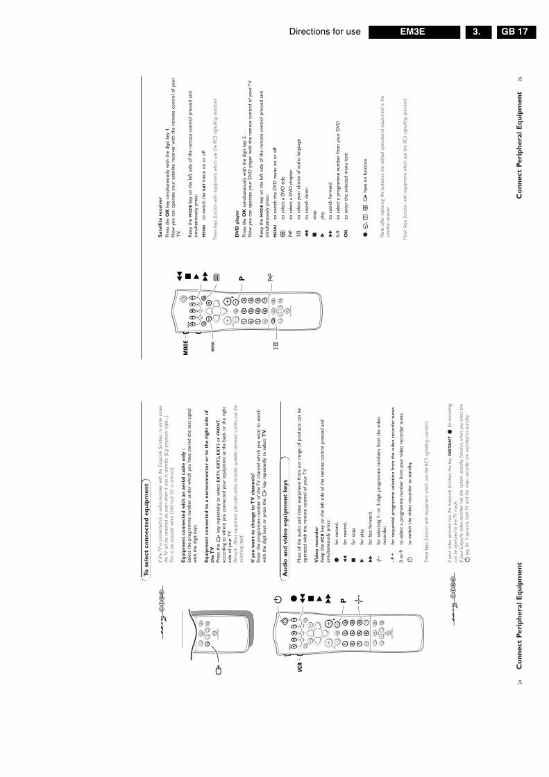
Directions for use GB 17EM3E 3.
25C
on
nec
t P
erip
her
al E
qu
ipm
ent
Sat
ellit
e re
ceiv
erPr
ess
the
OK
key
sim
ulta
neou
sly
with
the
dig
it ke
y 1.
Now
you
can
ope
rate
you
r sa
telli
te r
ecei
ver
with
the
rem
ote
cont
rol o
f you
rT
V.
Kee
p th
e M
OD
E k
ey o
n th
e le
ft s
ide
of t
he r
emot
e co
ntro
l pre
ssed
and
sim
ulta
neou
sly
pres
s:
ME
NU
to s
witc
h th
e S
AT
men
u on
or
off
Thes
e ke
ys f
unct
ion
with
equ
ipm
ent
whi
ch u
se t
he R
C5 s
igna
lling
stan
dard
.
DV
D p
laye
rPr
ess
the
OK
sim
ulta
neou
sly
with
the
dig
it ke
y 2.
Now
you
can
ope
rate
you
r D
VD
pla
yer
with
the
rem
ote
cont
rol o
f you
r T
V.
Kee
p th
e M
OD
E k
ey o
n th
e le
ft s
ide
of t
he r
emot
e co
ntro
l pre
ssed
and
sim
ulta
neou
sly
pres
s:
ME
NU
to s
witc
h th
e D
VD
men
u on
or
off
bto
sel
ect
a D
VD
titl
e
0to
sel
ect
a D
VD
chap
ter
Xto
sel
ect
your
cho
ice
of a
udio
lang
uage
Òto
sea
rch
dow
n
‡st
op
πpl
ay
†to
sea
rch
forw
ard
0-9
to s
elec
t a
prog
ram
me
num
ber
from
you
r D
VD
OK
to e
nter
the
sel
ecte
d m
enu
item
®,C
,f,h
,w h
ave
no fu
nctio
n
Not
e:af
ter
repl
acin
g th
e ba
tter
ies
the
defa
ult
oper
atio
nal e
quip
men
t is
the
sate
llite
rece
iver.
Thes
e ke
ys f
unct
ion
with
equ
ipm
ent
whi
ch u
se t
he R
C6 s
igna
lling
stan
dard
.
VP
SMA
RT
DN
R
ACT
IVE
CON
TRO
L
Ma
w
h
qbS
X
21
3
54
6
87
9
0
B
®Ò
‡π
†
¬
i0
fh
U
æ
MEN
U
b
OK
◊
INST
AN
TQ
Ò ‡ π †
X0b
MEN
U
yÚ
24C
on
nec
t P
erip
her
al E
qu
ipm
entIf
the
TV is
con
nect
ed t
o a
video
rec
orde
r w
ith t
he E
asyL
ink
func
tion,
in s
ome
case
sth
e TV
will
be s
witc
hed
on,e
ven
whe
n it
was
in s
tand
by.(
E.g.
play
back
tap
e,...)
This
is no
t po
ssib
le w
hen
Child
lock
On
is se
lect
ed.
Eq
uip
men
t co
nn
ecte
d w
ith
an
aer
ial
cabl
e o
nly
:Se
lect
the
pro
gram
me
num
ber
unde
r w
hich
you
hav
e st
ored
the
tes
t si
gnal
with
the
dig
it ke
ys.
Eq
uip
men
t co
nn
ecte
d t
o a
eu
roco
nn
ecto
r o
r to
th
e ri
ght
sid
e o
f th
e T
VPr
ess
the
wke
y re
peat
edly
to
sele
ct E
XT
1,E
XT
2,E
XT
3or
FR
ON
T,
acco
rdin
g to
whe
re y
ou c
onne
cted
you
r eq
uipm
ent
at t
he b
ack
or t
he r
ight
side
of y
our
TV.
Rem
ark
:Mos
t eq
uipm
ent
(dec
oder
,vid
eo r
ecor
der,
sate
llite
rece
iver)
car
ries
out
the
switc
hing
itse
lf.
If y
ou
wan
t to
ch
ange
to
TV
ch
ann
els?
Ente
r th
e pr
ogra
mm
e nu
mbe
r of
the
TV
cha
nnel
whi
ch y
ou w
ant
to w
atch
with
the
dig
it ke
ys o
r pr
ess
the
wke
y re
peat
edly
to
sele
ct T
V.
To s
elec
t co
nn
ecte
d e
qu
ipm
ent
Mos
t of
the
aud
io a
nd v
ideo
equ
ipm
ent
from
our
ran
ge o
f pro
duct
s ca
n be
oper
ated
with
the
rem
ote
cont
rol o
f you
r T
V.
Vid
eo r
eco
rder
Kee
p th
e V
CR
key
on t
he le
ft s
ide
of t
he r
emot
e co
ntro
l pre
ssed
and
sim
ulta
neou
sly
pres
s:
®fo
r re
cord
,
Òfo
r re
win
d,
‡fo
r st
op,
πfo
r pl
ay,
†fo
r fa
st fo
rwar
d,
◊fo
r se
lect
ing
1- o
r 2-
digi
t pr
ogra
mm
e nu
mbe
rs fr
om t
he v
ideo
reco
rder
,
- P
+fo
r se
quen
tial p
rogr
amm
e se
lect
ion
from
the
vid
eo r
ecor
der
tune
r,
0 to
9to
sel
ect
a pr
ogra
mm
e nu
mbe
r fr
om y
our
vide
o re
cord
er t
uner
,
Bto
sw
itch
the
vide
o re
cord
er t
o st
andb
y
Thes
e ke
ys f
unct
ion
with
equ
ipm
ent
whi
ch u
se t
he R
C5 s
igna
lling
stan
dard
.
If yo
ur v
ideo
rec
orde
r ha
s th
e Ea
syLi
nk f
unct
ion,
the
key
INS
TA
NT
®fo
r re
cord
ing,
can
be o
pera
ted
in t
he T
V m
ode.
If yo
ur E
asyL
ink
video
rec
orde
r ha
s th
e sy
stem
sta
ndby
fun
ctio
n,w
hen
you
pres
s th
eB
key
for
3 se
cond
s,bo
th T
V an
d th
e vid
eo r
ecor
der
are
switc
hed
to s
tand
by.
Au
dio
an
d v
ideo
eq
uip
men
t ke
ys
w
SMA
RT
ACT
IVE
CON
TRO
L
Ma
w
h
qbS
X
87
9
0i
0◊
VP
SMA
RT
DN
R
ACT
IVE
CON
TRO
L
Ma
w
h
qbS
X
21
3
54
6
87
9
0
B
®Ò
‡π
†
¬
i0
fh
U
æ
MEN
U
b
OK
◊
INST
AN
TQ
B ◊® Ò ‡ π †
yÚ

Directions for useGB 18 EM3E3.
27T
ips
& I
nd
ex
Car
e o
f th
e sc
reen
Cle
an t
he T
V w
ith a
slig
htly
dam
p so
ftcl
oth.
Do
not
use
abra
sive
sol
vent
as
itca
n da
mag
e th
e T
V s
cree
n.
Po
or
Pic
ture
•H
ave
you
sele
cted
the
cor
rect
TV
syst
em?
•Is
you
r T
V o
r ho
use
aeri
al lo
cate
d to
ocl
ose
to lo
udsp
eake
rs,n
on-e
arth
edau
dio
equi
pmen
t or
neo
n lig
hts,
etc.
?•
Mou
ntai
ns o
r hi
gh b
uild
ings
can
cau
sedo
uble
pic
ture
s or
gho
st im
ages
.So
met
imes
you
can
impr
ove
the
pict
ure
qual
ity b
y ch
angi
ng t
he d
irec
tion
of t
heae
rial
.•
Is t
he p
ictu
re o
r te
lete
xtun
reco
gnis
able
?C
heck
if y
ou h
ave
ente
red
the
corr
ect
freq
uenc
y.Se
e In
stal
latio
n,p.
5.•
Are
bri
ghtn
ess
and
cont
rast
out
of
adju
stm
ent?
Sel
ect
Fact
ory
sett
ings
inth
e Se
tup
men
u,p.
7.•
Som
etim
es p
oor
pict
ure
qual
ity is
poss
ible
whe
n ha
ving
act
ivat
ed a
n S-
VH
Sca
mer
a or
cam
cord
er c
onne
cted
to
the
righ
t si
de o
f you
r TV
and
ano
ther
peri
pher
al is
con
nect
ed t
o E
XT
1or
EX
T2
at t
he s
ame
time.
In t
his
case
switc
h of
f one
of t
he o
ther
per
iphe
rals
.
No
pic
ture
•Is
the
aer
ial c
onne
cted
pro
perl
y?
•A
re t
he p
lugs
tig
htly
con
nect
ed in
the
aeri
al s
ocke
t?•
Is t
he a
eria
l cab
le in
goo
d co
nditi
on a
nddo
es it
hav
e su
itabl
e pl
ugs?
•A
re t
he c
onne
ctio
n fa
cilit
ies
to a
pos
sibl
ese
cond
TV
in g
ood
cond
ition
?If i
n do
ubt,
cons
ult
your
dea
ler.
No
so
un
d•
No
soun
d on
any
cha
nnel
? C
heck
the
volu
me
isn’
t at
min
imum
.•
Is t
he s
ound
inte
rrup
ted
with
the
mut
eke
y ¬
?
Rem
ote
co
ntr
ol
If yo
ur T
Vno
long
er r
espo
nds
to t
here
mot
e co
ntro
l,th
e ba
tter
ies
may
be
dead
.Yo
u ca
n st
ill u
se t
he M
key
and
the
-/+
key
s at
the
top
of y
our
TV.
Men
uH
ave
you
sele
cted
the
wro
ng m
enu?
Pre
ssth
e M
EN
Uke
y ag
ain
to e
xit
from
the
men
u.
No
so
luti
on
Switc
h yo
ur T
V o
ff an
d th
en o
n ag
ain
once
.N
ever
att
emp
t to
rep
air
a d
efec
tive
TV
yo
urs
elf.
Che
ck w
ith y
our
deal
er o
r ca
ll a T
Vte
chni
cian
.
En
d o
f lif
e d
irec
tive
sPh
ilips
is p
ayin
g a
lot
of a
tten
tion
topr
oduc
e en
viro
nmen
tally
-fri
endl
y in
gre
enfo
cal a
reas
.You
r ne
w T
V c
onta
ins
mat
eria
lsw
hich
can
be
recy
cled
and
reu
sed.
At
the
end
of it
s lif
e sp
ecia
lised
com
pani
esca
n di
sman
tle t
he d
isca
rded
TV
to
conc
entr
ate
the
reus
able
mat
eria
ls a
nd t
om
inim
ise
the
amou
nt o
f mat
eria
ls t
o be
disp
osed
of.
Plea
se e
nsur
e yo
u di
spos
e of
you
r ol
d T
Vac
cord
ing
to lo
cal r
egul
atio
ns.
How
to
dis
po
se o
f b
atte
ries
?T
he b
atte
ries
sup
plie
d do
not
con
tain
the
heav
y m
etal
s m
ercu
ry a
nd c
adm
ium
.N
ever
thel
ess
in m
any
coun
trie
s ba
tter
ies
may
not
be
disp
osed
of w
ith y
our
hous
ehol
d w
aste
.Ple
ase
ensu
re y
ou d
ispo
seof
bat
teri
es a
ccor
ding
to
loca
l reg
ulat
ions
.
aA
CI,
5ac
tive
cont
rol,
10au
tom
atic
inst
alla
tion,
5au
to fo
rmat
,7
auto
sur
roun
d,8
AV
L,12
bbi
lingu
al b
road
cast
,10
cca
mco
rder
,23
child
lock
,13
cont
inuo
us s
ubtit
les,
21co
untr
y,4
dde
code
r/de
scra
mbl
er,
7de
lta v
olum
e,12
digi
tal o
ptio
ns,
11do
uble
line
s,11
dual
scr
een,
14D
VD
,25
dyna
mic
con
tras
t,11
eea
sy t
ext,
19eu
roca
ble,
22f
fact
ory
sett
ings
,7
favo
urite
pro
gram
mes
,6
free
ze,
10fr
eque
ncy,
5g
give
nam
e,6
grap
hic
equa
lizer
,12
hhe
adph
one,
23hu
e,11
iin
cred
ible
sur
roun
d,9
info
on
scre
en,
9in
form
atio
n lin
e,7
inte
rrup
t th
e so
und,
9l
lang
uage
,4
mm
anua
l ins
talla
tion,
5m
enu
lang
uage
,4
nna
tura
l mot
ion,
11N
EXT
VIE
W,
15ni
cam
,10
ppi
ctur
e ad
just
men
ts,
11pi
ctur
e fo
rmat
,10
pict
ure
tilt,
7pr
ogra
mm
e se
lect
ion,
9pr
ogra
mm
e lis
t,13
rre
cord
ing,
26
resh
uffle
,6
ssa
telli
te r
ecei
ver,
26se
arch
for
TV
cha
nnel
s,5
setu
p,7
slee
ptim
er,
13sm
art
pict
ure
and
soun
d,10
soun
d ad
just
men
ts,
12st
ereo
,10
stor
e T
V c
hann
els,
4su
bpag
es t
elet
ext,
20S-
VH
S,26
switc
h T
V o
n,3
tte
lete
xt,
19v
vide
o re
cord
er,
22V
irtu
al D
olby
Sur
roun
d,9
volu
me,
9
Tip
s
Ind
ex
26R
eco
rd
To r
ecor
d S-
VH
S qu
ality
,con
nect
an
S-V
HS
peri
pher
al d
irec
tly t
o th
e vi
deo
reco
rder
.
Rec
ord
a T
Vp
rogr
amm
e&
Sele
ct t
he p
rogr
amm
e nu
mbe
r on
you
r vi
deo
reco
rder
.
éSe
t yo
ur v
ideo
rec
orde
r to
rec
ord.
See
the
hand
book
for
your
vid
eo r
ecor
der.
Switc
hing
pro
gram
me
num
bers
on
your
TV
does
not
dist
urb
reco
rdin
g !
Rec
ord
a p
rogr
amm
e o
n y
ou
r vi
deo
rec
ord
er c
on
nec
ted
to
EX
TE
RN
AL
2fr
om
Au
dio
/Vid
eo e
qu
ipm
ent
con
nec
ted
to
E
XT
ER
NA
L 1
,EX
TE
RN
AL
3o
r to
so
cket
s o
n t
he
righ
t si
de
of
the
TV
&Sw
itch
on t
he e
quip
men
t.
éSe
lect
the
rig
ht e
xter
nal o
n yo
ur v
ideo
rec
orde
r.
“Se
t yo
ur v
ideo
rec
orde
r to
rec
ord.
You
reco
rd w
hat
you
are
wat
chin
g on
the
scr
een.
Do
not
switc
h pr
ogra
mm
e nu
mbe
rs o
r do
not
sw
itch
off
your
TV
whe
n yo
u ar
ere
cord
ing
!
Rec
ord
wit
h y
ou
r vi
deo
rec
ord
er
If yo
u ha
ve c
onne
cted
an
S-VH
S vid
eo r
ecor
der
prov
ided
with
the
Eas
yLin
k fu
nctio
n,yo
u ca
n re
cord
S-V
HS-
qual
ity f
rom
an
S-VH
S pe
riphe
ral c
onne
cted
to
the
right
sid
eof
the
TV.
(E.g
.fro
m a
n S-
VHS
cam
cord
er.)
In T
V m
ode,
it is
poss
ible
to
star
t a
dire
ct r
ecor
ding
of
the
prog
ram
me
whi
ch is
bei
ngdi
spla
yed
on t
he T
V sc
reen
.Pr
ess
the
INS
TA
NT
® r
ecor
d ke
y of
the
rem
ote
cont
rol.
The
video
rec
orde
r sw
itche
s on
fro
m s
tand
by a
nd a
mes
sage
of
wha
t is
bein
gre
cord
ed a
ppea
rs o
n th
e sc
reen
.Th
e vid
eo r
ecor
der
star
ts r
ecor
ding
the
pro
gram
me
you
are
wat
chin
g.Sw
itchi
ng p
rogr
amm
e nu
mbe
rs o
n yo
ur T
V do
es n
ot d
istur
b re
cord
ing
!
Whe
n re
cord
ing
a pr
ogra
mm
e fro
m a
per
iphe
ral c
onne
cted
to
EXTE
RNAL
1,3
orFR
ON
T,yo
u ca
n no
t se
lect
ano
ther
TV
prog
ram
me
on t
he s
cree
n.To
wat
ch T
V pr
ogra
mm
es a
gain
,pre
ss t
he p
rogr
amm
e nu
mbe
r yo
u w
ant
to s
elec
ttw
ice.
Atte
ntio
n:th
e re
cord
ing
is st
oppe
d an
d yo
ur v
ideo
rec
orde
r sw
itche
s to
sta
ndby
.
Rec
ord
wit
h y
ou
r vi
deo
rec
ord
er w
ith
Eas
yLin
k
If yo
ur v
ideo
rec
orde
r is
equi
pped
with
NEX
TVIE
WLi
nk,a
nd y
ou t
agge
d on
e or
mor
epr
ogra
mm
es t
o be
rec
orde
d au
tom
atic
ally
in t
he N
EXTV
IEW
mod
e,it
is no
t ne
cess
ary
for
the
TV t
o be
in t
he s
tand
by m
ode
or s
witc
hed
on fo
r th
e re
cord
ing
to s
tart
.
Rec
ord
wit
h y
ou
r vi
deo
rec
ord
er w
ith
NE
XT
VIE
WL
ink
VP
B
®Ò
‡π
†
¬fh
U
æ
MEN
U
b
OK
INST
AN
TQ
INST
AN
T
®y
Ú

Directions for use GB 19EM3E 3.
Tab
le o
f T
V f
req
uen
cies
.F
req
uen
ztab
elle
der
Fer
nse
hse
nd
er.
Lis
te d
es f
réq
uen
ces
des
ém
ette
urs
.F
req
uen
tiet
abel
TV
-Zen
der
s.Ta
bel
la d
elle
fre
qu
enze
del
le t
rasm
itte
nti
.L
ista
de
las
frec
uen
cias
de
las
emis
ora
s.L
ista
das
fre
qu
ênci
as d
os
emis
sore
s.L
iste
ove
r T
V s
end
ern
e.Ta
bel
l ove
r T
V-f
rekv
ense
r.
GB
The
freq
uenc
ies
used
by
a ca
ble
com
pany
may
diff
erfr
om th
e fr
eque
ncie
s on
the
tabl
e. C
onsu
lt yo
ur c
able
com
pany
or
your
dea
ler
for
deta
iled
info
rmat
ion.
D In K
abel
fern
seha
nlag
en k
önne
n A
bwei
chun
gen
von
den
in d
en F
requ
enzt
abel
len
aufg
efüh
rten
Fre
quen
zen
vo
rko
mm
en
. B
itte
we
nd
en
Sie
sic
h a
n I
hre
nF
achh
ändl
er o
der
Ihre
Kab
elfe
rnse
hges
ells
chaf
t, di
eIh
nen
die
zutr
effe
nden
Fre
quen
zen
mitt
eilt.
F Le
s f
réq
ue
nc
es
uti
lis
ée
s p
ar
un
e s
oc
iété
de
télé
dist
ribut
ion
peuv
ent ê
tre
diffé
rent
es d
e ce
lles
sur
la l
iste
des
fré
quen
ces.
Con
sulte
z vo
tre
soci
été
deté
léd
istr
ibu
tio
n o
u v
otr
e r
ev
en
de
ur
po
ur
de
sin
form
atio
ns p
lus
déta
ilées
.
NL
De
fre
qu
en
tie
s d
ie g
eb
ruik
t w
ord
en
do
or
ee
nka
belm
aats
chap
pij
kunn
en v
ersc
hille
n va
n de
ze o
pd
e t
ab
el.
Ra
ad
ple
eg
uw
ka
be
lexp
loit
an
t o
f u
wha
ndel
aar
voor
mee
r in
form
atie
.
I Le fr
eque
nze
usat
e pe
r una
soc
ietà
di t
eled
istri
buzi
one
po
ssa
no
ess
ere
diff
ere
nti
di
qu
elle
ne
lla t
ab
ella
.C
onsu
ltate
la
soci
età
di t
eled
istr
ibuz
ione
o i
l vo
stro
riven
dito
re p
er in
form
azio
ne s
peci
fica.
E La
s fr
ecu
en
cia
s u
tiliz
ad
as
po
r la
s e
mp
resa
s d
edi
strib
ució
n de
señ
al p
or c
able
, pue
den
ser
dife
rent
esde
las
que
se e
ncue
ntra
n en
est
a ta
bla.
Con
sulte
con
su c
ompa
ñia
de
dist
ribuc
ión
de te
levi
sión
por
cab
le o
con
su
dis
trib
uid
or
pa
ra q
ue
le
pro
po
rcio
ne
n u
na
info
rmac
ión
más
det
alla
da.
P As
fre
qu
ên
cia
s u
tiliz
ad
as
po
r u
ma
so
cie
da
de
de
tele
dist
ribui
ção
pode
m s
er d
ifere
ntes
das
indi
cada
s na
lista
de
fre
qu
ên
cia
s. C
on
sult
ar
a s
oci
ed
ad
e d
ete
ledi
strib
uiçã
o ou
o v
ende
dor
para
info
rmaç
ões
mai
sde
talh
adas
.
DK
Fre
kven
ser
beny
ttet
af
kabe
l op
erat
øre
r ka
n væ
reaf
vige
nde
fra
diss
e, k
anta
kt d
eres
kab
el o
pera
tør
elle
rfo
rhan
dler
for
næm
ere
info
rma-
tion.
N Fre
kven
sene
som
ben
ytte
s pa
et k
abel
nett
kan
avvi
kefr
a de
som
er
oppf
ört i
tabe
llen.
Kon
takt
ditt
kab
el-T
Vse
lska
p el
ler
din
forh
andl
er fo
r næ
mer
e op
plys
ning
er.
S Fre
kve
nse
rna
so
m a
nvä
nd
s i
kab
el-
TV
-nä
ten
ka
nav
vika
från
frek
vens
erna
i ta
belle
n. K
onta
kta
ditt
kabe
l-T
V-b
olag
elle
r di
n ra
dioh
andl
are
för
vida
re in
form
atio
n.
SF
Kaa
peliy
htiö
den
käyt
täm
ät t
aaju
udet
voi
vat
poik
eta
taul
ukos
sa o
levi
sta
taaj
uuks
ista
. Ta
rkat
tie
dot
saat
kaap
eliy
htiö
sta
tai m
yyjä
ltä.
GR
�ι
συ�ν
�τητ
ες
π�υ
�ρησ
ιµ�π
�ι�ύ
νται
απ
� µι
α ετ
αιρε
ίατη
λεµε
τάδ�
σης
είναι
δυν
ατ�ν
να
είναι
δια
��ρε
τικές
απ�
αυτ
έςπ�
υ πε
ριέ�
ει �
κατά
λ�γ�
ς.(Σ
υµ��
υλευ
θείτε
την
ετα
ιρεία
τηλε
µετά
δ�ση
ς ή τ�
ν πω
λητή
για
λεπτ
�µερ
έστε
ρες π
ληρ�
��ρί
ες).
CE
IH
asto
ty n
a ko
tory
x pe
red
aòt
tela
kam
pani
ä m
ogut
otli
hatæ
sä o
t ha
stot
na
dann
oj t
abli
ce. (
Obr
atit
æsä
k V
aπej
tel
ekam
pani
i il
i V
aπem
u pr
odav
cu
zad
opol
nite
læno
j in
for
mac
iej.
H Egy
te
levi
zió−
adóá
llom
ás
sugá
rzás
hoz
hasz
nált
frek
venc
iata
rtom
ánya
i le
hetn
ek
a tá
bláz
atba
nkö
zölte
ktől
elté
rőek
is.
(A
bban
az
eset
ben,
ha
bőve
bbin
form
áció
kra
van
szük
sége
, for
duljo
n az
ela
dóho
z.)
PL
Ope
rato
r si
eci
tele
wiz
yjne
j m
oże
stos
ować
in
necz
ęsto
tliw
ości
, ni
ż te
, kt
óre
figu
rują
na
ta
blic
y(b
ardz
iej
szcz
egół
owyc
h in
form
acji
na
ten
tem
atza
sięg
nąć
u op
erat
ora
lub
sprz
edaw
cy).
CZ
Frek
venc
e po
užív
ané
někt
erým
i tel
eviz
ním
i spo
lečn
ost−
mi s
e m
ohou
liši
t od
údaj
ů uv
eden
ých
v to
mto
sez
nam
u.In
form
ujte
se b
líže
u př
íslu
šné
spol
ečno
sti n
ebo
v pr
ode−
jně,
kde
jste
tele
vizo
r ko
upili
.
SK
Fre
kven
cie
použ
ívan
é ni
ekto
rým
i sp
oloč
nos9
ami
tele
vízn
eho
pren
osu
sa m
ôžu
liši9
od ú
dajo
v uv
eden
ých
vto
mto
zo
znam
e.
Info
rmuj
te
sa
bliž
šie
u pr
íslu
šnej
spol
očno
sti a
lebo
v p
reda
jni,
kde
ste
tele
vízo
r kú
pili.
Tab
ell ö
ver
TV
-fre
kven
ser.
TV
-taa
juu
stau
lukk
o.
Kα
τάλ�
γ�ς
συ�ν
�τή
των
π�µ
πώ
ν.S
pi
sok
has
tot
per
edat
hi
kov
.A
tel
eviz
ió−
adóá
llom
ások
fre
kven
ciái
nak
a lis
tája
.L
ista
czę
stot
liwoś
ci s
tacj
i nad
awcz
ych.
Sezn
am f
rekv
enčn
ích
páse
m v
ysíla
čů.
Zoz
nam
fre
kven
čnýc
h pá
siem
vys
iela
čov.
EU
RO
PE
CH
AN
NE
L....
..FR
EQ
(M
Hz)
E2
......
......
......
..48.
25E
3...
......
......
.....5
5.25
E4
......
......
......
..62.
25E
5...
......
......
...17
5.25
E6
......
......
......
182.
25E
7...
......
......
...18
9.25
E8
......
......
......
196.
25E
9...
......
......
...20
3.25
E10
......
......
....2
10.2
5E
11...
......
......
.217
.25
E12
......
......
....2
24.2
5S
1....
......
......
..105
.25
S2.
......
......
.....1
12.2
5S
3....
......
......
..119
.25
S4.
......
......
.....1
26.2
5S
5....
......
......
..133
.25
S6.
......
......
.....1
40.2
5S
7....
......
......
..147
.25
S8.
......
......
.....1
54.2
5S
9....
......
......
..161
.25
S10
......
......
....1
68.2
5S
11...
......
......
.231
.25
S12
......
......
....2
38.2
5S
13...
......
......
.245
.25
S14
......
......
....2
52.2
5S
15...
......
......
.259
.25
S16
......
......
....2
66.2
5S
17...
......
......
.273
.25
S18
......
......
....2
80.2
5S
19...
......
......
.287
.25
S20
......
......
....2
94.2
5H
1...
......
......
..303
.25
H2
......
......
.....3
11.2
5H
3...
......
......
..319
.25
H4
......
......
.....3
27.2
5H
5...
......
......
..335
.25
H6
......
......
.....3
43.2
5H
7...
......
......
..351
.25
H8
......
......
.....3
59.2
5H
9...
......
......
..367
.25
H10
......
......
...37
5.25
H11
......
......
...38
3.25
H12
......
......
...39
1.25
H13
......
......
...39
9.25
H14
......
......
...40
7.25
H15
......
......
...41
5.25
H16
......
......
...42
3.25
H17
......
......
...43
1.25
H18
......
......
...43
9.25
H19
......
......
...44
7.25
21...
......
......
...47
1.25
22...
......
......
...47
9.25
23...
......
......
...48
7.25
24...
......
......
...49
5.25
25...
......
......
...50
3.25
26...
......
......
...51
1.25
27...
......
......
...51
9.25
28...
......
......
...52
7.25
29...
......
......
...53
5.25
30...
......
......
...54
3.25
31...
......
......
...55
1.25
32...
......
......
...55
9.25
33...
......
......
...56
7.25
34...
......
......
...57
5.25
35...
......
......
...58
3.25
36...
......
......
...59
1.25
37...
......
......
...59
9.25
38...
......
......
...60
7.25
39...
......
......
...61
5.25
40...
......
......
...62
3.25
41...
......
......
...63
1.25
42...
......
......
...63
9.25
43...
......
......
...64
7.25
44...
......
......
...65
5.25
45...
......
......
...66
3.25
46...
......
......
...67
1.25
47...
......
......
...67
9.25
48...
......
......
...68
7.25
49...
......
......
...69
5.25
50...
......
......
...70
3.25
51...
......
......
...71
1.25
52...
......
......
...71
9.25
53...
......
......
...72
7.25
54...
......
......
...73
5.25
55...
......
......
...74
3.25
56...
......
......
...75
1.25
57...
......
......
...75
9.25
58...
......
......
...76
7.25
59...
......
......
...77
5.25
60...
......
......
...78
3.25
61...
......
......
...79
1.25
62...
......
......
...79
9.25
63...
......
......
...80
7.25
64...
......
......
...81
5.25
65...
......
......
...82
3.25
66...
......
......
...83
1.25
67...
......
......
...83
9.25
68...
......
......
...84
7.25
69...
......
......
...85
5.25
ITA
LYC
AN
ALE
......
..FR
EQ
(M
Hz)
A...
......
......
......
53.7
5B
......
......
......
....6
2.25
C...
......
......
......
.82.
25D
......
......
......
.175
.25
E...
......
......
.....1
83.7
5F
......
......
......
..192
.25
G...
......
......
....2
01.2
5H
......
......
......
.210
.25
H1
......
......
.....2
17.2
5S
1....
......
......
..105
.25
S2.
......
......
.....1
12.2
5S
3....
......
......
..119
.25
S4.
......
......
.....1
26.2
5S
5....
......
......
..133
.25
S6.
......
......
.....1
40.2
5S
7....
......
......
..147
.25
S8.
......
......
.....1
54.2
5S
9....
......
......
..161
.25
S10
......
......
....1
68.2
5S
11...
......
......
.231
.25
S12
......
......
....2
38.2
5S
13...
......
......
.245
.25
S14
......
......
....2
52.2
5S
15...
......
......
.259
.25
S16
......
......
....2
66.2
5S
17...
......
......
.273
.25
S18
......
......
....2
80.2
5S
19...
......
......
.287
.25
S20
......
......
....2
94.2
5H
1...
......
......
..303
.25
H2
......
......
.....3
11.2
5H
3...
......
......
..319
.25
H4
......
......
.....3
27.2
5H
5...
......
......
..335
.25
H6
......
......
.....3
43.2
5H
7...
......
......
..351
.25
H8
......
......
.....3
59.2
5H
9...
......
......
..367
.25
H10
......
......
...37
5.25
H11
......
......
...38
3.25
H12
......
......
...39
1.25
H13
......
......
...39
9.25
H14
......
......
...40
7.25
H15
......
......
...41
5.25
H16
......
......
...42
3.25
H17
......
......
...43
1.25
H18
......
......
...43
9.25
H19
......
......
...44
7.25
21...
......
......
...47
1.25
22...
......
......
...47
9.25
23...
......
......
...48
7.25
24...
......
......
...49
5.25
25...
......
......
...50
3.25
26...
......
......
...51
1.25
27...
......
......
...51
9.25
28...
......
......
...52
7.25
29...
......
......
...53
5.25
30...
......
......
...54
3.25
31...
......
......
...55
1.25
32...
......
......
...55
9.25
33...
......
......
...56
7.25
34...
......
......
...57
5.25
35...
......
......
...58
3.25
36...
......
......
...59
1.25
37...
......
......
...59
9.25
38...
......
......
...60
7.25
39...
......
......
...61
5.25
40...
......
......
...62
3.25
41...
......
......
...63
1.25
42...
......
......
...63
9.25
43...
......
......
...64
7.25
44...
......
......
...65
5.25
45...
......
......
...66
3.25
46...
......
......
...67
1.25
47...
......
......
...67
9.25
48...
......
......
...68
7.25
49...
......
......
...69
5.25
50...
......
......
...70
3.25
51...
......
......
...71
1.25
52...
......
......
...71
9.25
53...
......
......
...72
7.25
54...
......
......
...73
5.25
55...
......
......
...74
3.25
56...
......
......
...75
1.25
57...
......
......
...75
9.25
58...
......
......
...76
7.25
59...
......
......
...77
5.25
60...
......
......
...78
3.25
61...
......
......
...79
1.25
62...
......
......
...79
9.25
63...
......
......
...80
7.25
64...
......
......
...81
5.25
65...
......
......
...82
3.25
66...
......
......
...83
1.25
67...
......
......
...83
9.25
68...
......
......
...84
7.25
69...
......
......
...85
5.25
FR
AN
CE
CA
NA
L....
......
.FR
EQ
(M
Hz)
2...
......
......
......
.55.
753
......
......
......
....6
0.50
4...
......
......
......
.63.
755
......
......
......
....1
76.0
6...
......
......
......
.184
.07
......
......
......
....1
92.0
8...
......
......
......
.200
.09
......
......
......
....2
08.0
10...
......
......
.....2
16.0
B...
......
......
.....1
16.7
5C
......
......
......
..128
.75
D...
......
......
....1
40.7
5E
......
......
......
..159
.75
F...
......
......
.....1
64.7
5G
......
......
......
.176
.75
H...
......
......
....1
88.7
5I.
......
......
......
..200
.75
J...
......
......
.....2
12.7
5K
......
......
......
..224
.75
L...
......
......
.....2
36.7
5M
......
......
......
.248
.75
N...
......
......
....2
60.7
5O
......
......
......
.272
.75
P...
......
......
.....2
84.7
5Q
......
......
......
.296
.75
H1
......
......
.....3
03.2
5H
2...
......
......
..311
.25
H3
......
......
.....3
19.2
5H
4...
......
......
..327
.25
H5
......
......
.....3
35.2
5H
6...
......
......
..343
.25
H7
......
......
.....3
51.2
5H
8...
......
......
..359
.25
H9
......
......
.....3
67.2
5H
10...
......
......
375.
25H
11...
......
......
383.
25H
12...
......
......
391.
25H
13...
......
......
399.
25H
14...
......
......
407.
25H
15...
......
......
415.
25H
16...
......
......
423.
25H
17...
......
......
431.
25H
18...
......
......
439.
25H
19...
......
......
447.
2521
......
......
......
471.
2522
......
......
......
479.
2523
......
......
......
487.
2524
......
......
......
495.
2525
......
......
......
503.
2526
......
......
......
511.
2527
......
......
......
519.
2528
......
......
......
527.
2529
......
......
......
535.
2530
......
......
......
543.
2531
......
......
......
551.
2532
......
......
......
559.
2533
......
......
......
567.
2534
......
......
......
575.
2535
......
......
......
583.
2536
......
......
......
591.
2537
......
......
......
599.
2538
......
......
......
607.
2539
......
......
......
615.
2540
......
......
......
623.
2541
......
......
......
631.
2542
......
......
......
639.
2543
......
......
......
647.
2544
......
......
......
655.
2545
......
......
......
663.
2546
......
......
......
671.
2547
......
......
......
679.
2548
......
......
......
687.
2549
......
......
......
695.
2550
......
......
......
703.
2551
......
......
......
711.
2552
......
......
......
719.
2553
......
......
......
727.
2554
......
......
......
735.
2555
......
......
......
743.
2556
......
......
......
751.
2557
......
......
......
759.
2558
......
......
......
767.
2559
......
......
......
775.
2560
......
......
......
783.
2561
......
......
......
791.
2562
......
......
......
799.
2563
......
......
......
807.
2564
......
......
......
815.
2565
......
......
......
823.
2566
......
......
......
831.
2567
......
......
......
839.
2568
......
......
......
847.
2569
......
......
......
855.
25
EA
ST
ER
N E
UR
OP
EC
AN
AL.
......
....F
RE
Q (
MH
z)R
1....
......
......
....4
9.75
R2.
......
......
......
.59.
25R
3....
......
......
....7
7.25
R4.
......
......
......
.85.
25R
5....
......
......
....9
3.25
R 6
......
......
.....1
75.2
5R
7...
......
......
..183
.25
R 8
......
......
.....1
91.2
5R
9...
......
......
..199
.25
R10
......
......
....2
07.2
5R
11...
......
......
.215
.25
R12
......
......
....2
23.2
5S
1....
......
......
..105
.25
S2.
......
......
.....1
12.2
5S
3....
......
......
..119
.25
S4.
......
......
.....1
26.2
5S
5....
......
......
..133
.25
S6.
......
......
.....1
40.2
5S
7....
......
......
..147
.25
S8.
......
......
.....1
54.2
5S
9....
......
......
..161
.25
S10
......
......
....1
68.2
5S
11...
......
......
.231
.25
S12
......
......
....2
38.2
5S
13...
......
......
.245
.25
S14
......
......
....2
52.2
5S
15...
......
......
.259
.25
S16
......
......
....2
66.2
5S
17...
......
......
.273
.25
S18
......
......
....2
80.2
5S
19...
......
......
.287
.25
S20
......
......
....2
94.2
5H
1...
......
......
..303
.25
H2
......
......
.....3
11.2
5H
3...
......
......
..319
.25
H4
......
......
.....3
27.2
5H
5...
......
......
..335
.25
H6
......
......
.....3
43.2
5H
7...
......
......
..351
.25
H8
......
......
.....3
59.2
5H
9...
......
......
..367
.25
H10
......
......
...37
5.25
H11
......
......
...38
3.25
H12
......
......
...39
1.25
H13
......
......
...39
9.25
H14
......
......
...40
7.25
H15
......
......
...41
5.25
H16
......
......
...42
3.25
H17
......
......
...43
1.25
H18
......
......
...43
9.25
H19
......
......
...44
7.25
21...
......
......
...47
1.25
22...
......
......
...47
9.25
23...
......
......
...48
7.25
24...
......
......
...49
5.25
25...
......
......
...50
3.25
26...
......
......
...51
1.25
27...
......
......
...51
9.25
28...
......
......
...52
7.25
29...
......
......
...53
5.25
30...
......
......
...54
3.25
31...
......
......
...55
1.25
32...
......
......
...55
9.25
33...
......
......
...56
7.25
34...
......
......
...57
5.25
35...
......
......
...58
3.25
36...
......
......
...59
1.25
37...
......
......
...59
9.25
38...
......
......
...60
7.25
39...
......
......
...61
5.25
40...
......
......
...62
3.25
41...
......
......
...63
1.25
42...
......
......
...63
9.25
43...
......
......
...64
7.25
44...
......
......
...65
5.25
45...
......
......
...66
3.25
46...
......
......
...67
1.25
47...
......
......
...67
9.25
48...
......
......
...68
7.25
49...
......
......
...69
5.25
50...
......
......
...70
3.25
51...
......
......
...71
1.25
52...
......
......
...71
9.25
53...
......
......
...72
7.25
54...
......
......
...73
5.25
55...
......
......
...74
3.25
56...
......
......
...75
1.25
57...
......
......
...75
9.25
58...
......
......
...76
7.25
59...
......
......
...77
5.25
60...
......
......
...78
3.25
61...
......
......
...79
1.25
62...
......
......
...79
9.25
63...
......
......
...80
7.25
64...
......
......
...81
5.25
65...
......
......
...82
3.25
66...
......
......
...83
1.25
67...
......
......
...83
9.25
68...
......
......
...84
7.25
69...
......
......
...85
5.25
28G
loss
ary
100
Hz
100
Her
tz p
rovi
des
a su
peri
or s
olut
ion
toth
e pr
oble
m o
f pic
ture
flic
ker
whi
ch is
part
icul
arly
not
icea
ble
with
larg
er s
cree
nsi
zes.
In a
con
vent
iona
l TV,
the
pict
ure
area
is s
cann
ed 5
0 tim
es a
sec
ond
(50
Her
tz)
–a
freq
uenc
y w
hich
is s
till d
etec
tabl
e by
the
hum
an e
ye in
the
form
of a
flic
keri
ngpi
ctur
e.In
100
Her
tz s
ets,
the
pict
ure
area
is s
cann
ed a
t a
rate
of 1
00 t
imes
per
seco
nd (
100
Her
tz).
At
this
freq
uenc
y,th
eey
e ca
nnot
det
ect
flick
er,r
esul
ting
in a
clea
rer
pict
ure
whi
ch is
mor
e re
laxi
ng t
oth
e ey
e.
Aut
omat
ic C
hann
el I
nsta
llati
on(A
CI)
Aut
omat
ical
ly in
stal
ls a
ll T
V c
hann
els
inth
e sa
me
orde
r as
offe
red
by y
our
cabl
eco
mpa
ny,p
rovi
ded
of c
ours
e th
at t
he d
ata
is t
rans
mitt
ed.I
t al
so a
utom
atic
ally
incl
udes
pro
gram
me
num
ber
and
prog
ram
me
nam
e.W
ith A
CI,
chan
nel i
nsta
llatio
n is
fully
auto
mat
ic,s
impl
e an
d fa
st.
Chi
ld lo
ckFe
atur
e to
pre
vent
una
utho
rise
d us
e of
your
TV.
Dig
ital
Sca
nIf
you
look
at
a te
levi
sion
scr
een
you
will
see
smal
l im
perf
ectio
ns in
the
pic
ture
caus
ed b
y lin
e vi
brat
ion.
Dig
ital S
can
(an
inte
rnal
pro
cess
) re
mov
es in
terl
ine
flick
er.
Whe
n co
mbi
ned
with
100
Hz,
you
will
see
a to
tally
sta
ble
imag
e.
Eas
y L
ink
Dig
ital ‘
inte
llige
nt’ E
SI b
us-s
yste
m b
etw
een
TV
and
VC
R (
Scar
t co
nnec
tion
requ
ired
).Tu
rns
sour
ce s
elec
tion
and
cont
rol i
nto
aon
e-bu
tton
ope
ratio
n.
Eas
y Te
xtTe
lete
xt m
emor
y th
at a
utom
atic
ally
mem
oris
es T
elet
ext
page
s an
d gi
ves
you
inst
ant
acce
ss t
o th
em.
Eur
ocon
nect
orA
21-
pin
conn
ecto
r sy
stem
ena
blin
g yo
uto
sim
ply
conn
ect
vari
ous
type
s of
audi
o/vi
deo
and
com
pute
r eq
uipm
ent.
Men
uO
n-sc
reen
dis
play
of f
unct
ions
and
faci
litie
s in
a w
ell-o
rgan
ised
sur
vey,
whi
chyo
u ca
n se
lect
usi
ng y
our
rem
ote
cont
rol.
NE
XT
VIE
W
NEX
TV
IEW
is a
new
feat
ure
to a
ssis
t th
e T
Van
d V
CR
use
r in
sel
ectin
g th
e pr
ogra
mm
essh
e or
he
likes
to
wat
ch fr
om a
tel
evis
ion
prog
ram
me
guid
e on
the
scr
een.
It e
nabl
esth
e us
er t
o se
e a
desc
ript
ion
of e
very
prog
ram
me,
and
mar
k in
tere
stin
gpr
ogra
mm
es t
o be
rem
inde
d (a
uto
TV
on)
or r
ecor
ded
(NEX
TV
IEW
Link
vid
eore
cord
er r
equi
red)
.
NT
SCT
he b
road
cast
ing
syst
em u
sed
in t
he U
SA,
Japa
n an
d pa
rts
of S
outh
Am
eric
a an
dSo
uthe
ast-
Asi
a.
Smar
t P
ictu
re a
nd S
ound
con
trol
sK
eys
on t
he r
emot
e co
ntro
l to
sele
ctpr
edef
ined
pic
ture
and
sou
nd s
ettin
gs.
Slee
ptim
erFu
nctio
n w
ith w
hich
you
can
set
a t
ime
peri
od a
fter
whi
ch t
he T
V s
houl
d sw
itch
itsel
f to
stan
dby.
Pic
ture
Fre
eze
TV
mod
e w
hich
allo
ws
you
to “
free
ze”
ace
rtai
n im
age
in o
rder
to
stud
y a
spec
ific
deta
il at
eas
e,e.
g.to
mak
e no
tes
of c
erta
inpr
ogra
mm
e in
form
atio
n lik
e ph
one
num
bers
.
Tele
text
See
also
Eas
y Te
xtW
ST:W
orld
Sta
ndar
d Te
lete
xt.
FLO
F:Fu
ll Le
vel o
ne F
eatu
res.
Syst
emap
plie
d by
the
BBC
,RV
E....
that
pro
vide
s a
fast
acc
ess
to t
he t
elet
ext
page
s.TO
P:Ta
ble
of (
Tele
text
) Pa
ges.
Ger
man
syst
em fo
r an
eas
y ac
cess
to
the
tele
text
page
s.
Tin
t
TV-
func
tion
to m
odify
the
gen
eral
col
our
bala
nce
betw
een
cool
and
war
m a
nd t
oad
just
it a
ccor
ding
to
your
per
sona
lpr
efer
ence
.
Glo
ssar
y

Mechanical InstructionsGB 20 EM3E4.
4. Mechanical Instructions
Note: Figures below can deviate slightly from the actualsituation, due to the different set executions.
4.1 Access to the Service Connector (forComPair)
1. Remove the 'Service Connector' cover (see Figure 4.1).2. Connect the ComPair cable (for more info, see chapter
5).3. Start ComPair and perform the diagnosis.
4.2 Rear Cover Removal
1. Remove all fixation screws [A] of the rear cover.2. Use a knife (or other thin blade) to release the four
fixation clamps [B] at the top of the TV-set. Press downuntil you here a click.
3. Now remove the rear cover.
Figure 4-1 .eps
4.3 Print Removal
4.3.1 Large Signal Panel (LSP)
Service position 1: For better accessibility of the LSP, do thefollowing (see Figure 4.2):1. Remove the LSP-bracket from the bottom tray by pulling
it backwards.2. Hook the bracket in the first row of fixation holes of the
bottom tray. In other words, reposition the bracket from[1] to [2].
Figure 4-2 .eps
Service position 2: To get access to the bottom side (solderside) of the LSP, do the following (see Figure 4.3):1. To disconnect the degaussing coil from the LSP, remove
the cable from connector 1502 [1].2. Release the wiring from their fixation clamps, in order to
get room for repositioning the LSP.3. Flip the LSP 90 degrees clockwise [2], and place it in the
fixation hole at the left side of the bottom tray [3].
Figure 4-3 .eps
4.3.2 3rd SCART Panel
To remove the 3rd SCART module, do the following:1. Remove the fixation screw [1].2. To release the fixation peg, push it towards the CRT [2].3. At the same time, pull the complete module away from
the LSP [3]. It hinges in the LSP-bracket.4. To remove the panel, disconnect the flat-cable from
connector 1680 and remove the four panel screws [4].
Figure 4-4 .eps
CL16532044_005.eps090501
A
A
A Aservice
connectorcover
A
A
A
B B B B
AUDIO OUT
SURR.
L
R
A
A
A
CL 16532044_003.eps100501
Bottom tray2
1
1
LSP
LOT - bracket
SSB
SSB - bracket
2
CL 16532044_006.eps140501
3
4
1
1502
2
CL 16532044_010.eps140501
1
3
4 4
1680
2

Mechanical Instructions GB 21EM3E 4.
4.3.3 Small Signal Board (SSB)
In fact, there is no predefined service position for the SSB.Most test points are located on the A-side (side that is facingthe tuner).If you have to replace ICs, you must take the complete SSBmodule out of the SIMM-connector.
To get access to the SSB test points, do the following:1. Put the LSP in service position 1 (as described above).2. Remove the fixation screw, which holds the SSB-bracket
[1].3. Release the clamping jaw at the top of the SSB bracket
[2] and [3].4. Push the two clamping lugs outwards, and pull the top of
the bracket at the same time upwards [4] and [5].5. Now you can remove the complete bracket. Push it, at
the height of the LSP-bracket, towards the CRT [6] andlift it out of the LSP-bracket [7].
Figure 4-5 .eps
1. Push the top of the SSB towards the LOT [1].2. Due to the pressure, the two metal clamps at both sides
of the SIMM-connector will release [2].3. Take the complete SSB out [3].
Figure 4-6 .eps
1. Once you have taken out the SSB, remove the A-sideshielding [2]. Sometimes it is necessary to unsoldersome solder-tags first [1].
2. Now replace the SSB module in the SIMM-connector inreverse order.
Figure 4-7
Note 1: For better access to the SSB, it is possible to orderan ‘extension board’ under number 9965 000 07933.Note 2: If necessary for the measurement, put the LSP in'service position 2' (as described above).
4.3.4 Top Control Panel
1. Remove the two fixation screws.2. Pull the board backward.
Figure 4-8
4.3.5 Side I/O Panel
1. Remove the two fixation screws [1].2. Push the panel door inside and fix it in the lock [2].3. Pull the module backward [3].4. Now release the fixation clamps, in order to remove the
print from its bracket.
Figure 4-9 .eps
CL 16532044_027.eps160501
37
6
7
6
4
4
2
1
5
3
2
1
SSB
2
3
CL 16532044_007.eps090501
2
CL 16532044_008.eps090501
21
1
SAM (4005)
SDM (4006)
CL96532137_009.eps101199
Top control board
CL 16532044_009.eps090501
1
31
2

Mechanical InstructionsGB 22 EM3E4.
4.3.6 DAF Panel
1. Remove the fixation screw [1].2. Push down the fixation clamp [2], and pull the complete
bracket at the same time away from the CRT [3]. Themodule is now free from the LSP-bracket.
3. Release the fixation clamps [4], in order to remove theprint from its bracket.
Figure 4-10 .eps
4.3.7 Mains Switch / LED Panel
1. Release the two fixation clamps by pushing them upward[1].
2. At the same time, pull the complete assy backward [2].3. Now release the two fixation clamps [3], in order to
remove the print from its bracket [4].
Figure 4-11 .eps
Note: If necessary, you can replace the light guide.
4.4 Rear Cover Assembly
Before you re-assemble the rear cover, perform the followingchecks:• Check whether the mains cord is mounted correctly in
the guiding brackets.• Check whether all cables are placed in fixation clamps.
This is very important due to the large 'hot' area of theset.
CL 16532044_011.eps150501
4
1
3
4
3
2
CL 16532044_012.eps090501
31
4
2
3
1

Service Modes, Error Codes and Fault Finding GB 23EM3E 5.
5. Service Modes, Error Codes and Fault Finding
Index of this chapter:1. Test points.2. Service Modes.3. Problems and solving tips (related to CSM).4. ComPair.5. Error buffer.6. The blinking LED procedure.7. Protections.8. Repair tips.
5.1 Test Points
The chassis is equipped with test points printed on the circuitboard assemblies. They refer to the diagram letters. Thenumbering is in a logical sequence for diagnostics. Alwaysstart diagnosing (within a functional block), in the sequenceof the relevant test points for that block.
Measurements are performed under the following conditions:• Service Default Mode.• Video: colour bar signal.• Audio: 3 kHz left, 1 kHz right.
5.2 Service Modes
Service Default Mode (SDM) and Service Alignment Mode(SAM) offer several features for the service technician, whilethe Customer Service Menu (CSM) is used forcommunication between dealer and customer.
5.2.1 Service Default Mode (SDM)
Purpose• To create a pre-defined setting, to get the same
measurement results as given in this manual.• To override SW protections.• To start the blinking LED procedure.
Specifications• Tuning frequency: 475.25 MHz for PAL/SECAM.• Colour system: SECAM L for France or PAL B/G for the
rest of Europe.• All picture settings at 50 % (brightness, colour, contrast).• All sound settings at 50 %, except volume at 25 %.• All service-unfriendly modes (if present) are disabled,
like:– (sleep) timer,– child/parental lock,– blue mute,– automatic volume limiter (AVL),– auto switch-off (when no ‘IDENT’ video signal was
received for 10 minutes),– skip/blank of non-favorite pre-sets,– smart modes,– auto store of personal presets,– auto user menu time-out.
How to enter SDMUse one of the following methods:• Via a standard customer RC-transmitter : key in the code
‘062596’ followed by the ‘MENU’ button (it is possiblethat, together with the SDM, the main menu will appear.To switch it off, push the ‘MENU’ button again).
• When you press the ‘DEFAULT’ button on the DealerService Tool (DST or RC7150) while the set is in thenormal operation mode.
• When you shorten for a moment (*) the two solder padson the ‘external part’ of the SSB print (see Figure 7 inChapter 4), with the indication SDM (item 4006).
Activation can be performed in all modes, except whenthe set has a problem with the main-processor.
• Via ComPair.* Caution: If the SDM is entered via the pins, all the software-controlled protections are de-activated.After entering SDM, the following screen will be shown, with‘Service Default’ at the lower right side for recognition.
Figure 5-1
How to navigateWhen you press the ‘MENU’ button on the RC transmitter,the set will toggle between the SDM and the normal usermenu (with the SDM mode still active in the background).
How to exit SDMUse one of the following methods:• Switch the set to STANDBY (�) via the RC-transmitter,
or• Press the ‘EXIT’ button on the DST.
5.2.2 Service Alignment Mode (SAM)
Purpose• To perform alignments.• To change option settings.• To display/clear the error code buffer.
Specifications• Operation hours counter.• Software version.• Option settings.• Error buffer reading and erasing.• Software alignments.
How to enter SAMUse one of the following methods:• Via a standard RC transmitter: key in the code ‘062596’
directly followed by the OSD [i+] button, or• When you press the ALIGN button on the DST while the
set is in the normal operation mode, or• When you shorten for a moment (*) the two solder pads
on the ‘external part’ of the SSB print (see Figure 7 inChapter 4), with the indication SAM (item 4005).Activation can be performed in all modes, except whenthe set has a problem with the main-processor.
• Via ComPair.
* Caution: If the SAM is entered via the pins, all the softwarecontrolled protections are de-activated.The following screen will be shown, with SAM at the upperright side for recognition.
S e r v i c e D e f a u l t
CL 16532044_031.eps140501
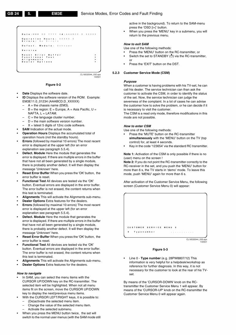
Service Modes, Error Codes and Fault FindingGB 24 EM3E5.
Figure 5-2
• Date Displays the software date.• ID Displays the software version of the ROM. Example:
EM3E11.0_01234 (AAABCD.D_XXXXX)– A = the chassis name (EM3).– B = the region: E = Europe, A = Asia Pacific, U =
NAFTA, L = LATAM.– C = the language cluster number.– D = the main software version number.– X = latest 5 digits of 12nc code software.
• SAM Indication of the actual mode.• Operation Hours Displays the accumulated total of
operation hours (not the standby hours).• Errors (followed by maximal 10 errors) The most recent
error is displayed at the upper left (for an errorexplanation see paragraph 5.5.4).
• Defect. Module Here the module that generates theerror is displayed. If there are multiple errors in the bufferthat have not all been generated by a single module,there is probably another defect. It will then display themessage 'Unknown' here.
• Reset Error Buffer When you press the 'OK' button, theerror buffer is reset.
• Functional Test All devices are tested via the 'OK'button. Eventual errors are displayed in the error buffer.The error buffer is not erased, the content returns whenthis test is terminated.
• Alignments This will activate the Alignments sub-menu.• Dealer Options Extra features for the dealers.• Errors (followed by maximal 10 errors) The most recent
error is displayed at the upper left (for an errorexplanation see paragraph 5.5.4).
• Defect. Module Here the module that generates theerror is displayed. If there are multiple errors in the bufferthat have not all been generated by a single module,there is probably another defect. It will then display themessage 'Unknown' here.
• Reset Error Buffer When you press the 'OK' button, theerror buffer is reset.
• Functional Test All devices are tested via the 'OK'button. Eventual errors are displayed in the error buffer.The error buffer is not erased, the content returns whenthis test is terminated.
• Alignments This will activate the Alignments sub-menu.• Dealer Options Extra features for the dealers.
How to navigate• In SAM, you can select the menu items with the
CURSOR UP/DOWN key on the RC-transmitter. Theselected item will be highlighted. When not all menuitems fit on the screen, move the CURSOR UP/DOWNkey to display the next/previous menu items.
• With the CURSOR LEFT/RIGHT keys, it is possible to:– (De)activate the selected menu item.– Change the value of the selected menu item.– Activate the selected submenu.
• When you press the MENU button twice, the set willswitch to the normal user menus (with the SAM mode still
active in the background). To return to the SAM-menupress the ‘OSD [i+]’ button.
• When you press the ‘MENU’ key in a submenu, you willreturn to the previous menu.
How to exit SAMUse one of the following methods:• Press the ‘MENU’ button on the RC-transmitter, or• Switch the set to STANDBY (�) via the RC-transmitter,
or• Press the ‘EXIT’ button on the DST.
5.2.3 Customer Service Mode (CSM)
PurposeWhen a customer is having problems with his TV-set, he cancall his dealer. The service technician can than ask thecustomer to activate the CSM, in order to identify the statusof the set. Now, the service technician can judge theseverness of the complaint. In a lot of cases he can advisethe customer how to solve the problem, or he can decide if itis necessary to visit the customer.The CSM is a read only mode, therefore modifications in thismode are not possible.
How to enter CSMUse one of the following methods:• Press the ‘MUTE’ button on the RC-transmitter
simultaneously with the ‘MENU’ button on the TV (topcontrol) for, at least 4 seconds.
• Key in the code ‘123654’ via the standard RC transmitter.
Note 1: Activation of the CSM is only possible if there is no(user) menu on the screen !Note 2: If you do not point the RC-transmitter correctly to theRC-receiver in the set, and you push the ‘MENU’ button formore than 6 s, the TV starts in ‘demo’ mode. To leave thismode, push ‘MENU’ again for more than 6 s.
After activation of the Customer Service Menu, the followingscreen (Customer Service Menu 0) will appear:
Figure 5-3
• Line 0 - Type number (e.g. 28PW8807/12) Thisinformation is very helpful for a helpdesk/workshop asreference for further diagnosis. In this way, it is notnecessary for the customer to look at the rear of his TV-set.
By means of the 'CURSOR-DOWN' knob on the RC-transmitter the Customer Service Menu 1 will appear. Bymeans of the 'CURSOR-UP' knob on the RC-transmitter theCustomer Service Menu 0 will appear again.
D a t e : M M M D D Y Y Y Y I d : A A A B C D . D _ X X X X X
O p e r a t i o n H o u r s : X X X X X . XE r r o r s : N o E r r o r s
D e f e c t . M o d u l e : U n k n o w n
S e r v i c e
R e s e t E r r o r B u f f e r >F u n c t i o n a l T e s t >A l i g n m e n t s >D e a l e r O p t i o n s >
CL16532044_032.eps140501
C U S T O M E R S E R V I C E M E N U 0
0 T y p e n u m b e r . . . . . . . . . . .
CL16532044_033.eps140501

Service Modes, Error Codes and Fault Finding GB 25EM3E 5.
Customer Service Menu 1 represents following information:
Figure 5-4
• Line 1 - Software version (e.g. EM3E11.0_XXXXX) Thebuild in software version. You will find details of thesoftware versions in the chapter 'Software Survey' of the'Product Survey - Colour Television' publication. Thispublication is generated four times a year.
• Line 2 - Code 1 Gives the last 5 errors of the error buffer.As soon as the built-in diagnose software has detectedan error the buffer is adapted. See paragraph 5.5.4 for adescription.
• Line 3 - Code 2 Gives the first 5 errors of the error buffer.As soon as the built-in diagnose software has detectedan error the buffer is adapted. The last occurred error isdisplayed on the leftmost position of code 2. Each errorcode is displayed as a 3 digit number. When less than 10errors occur, the rest of the line(s) is (are) empty. In caseof no errors the text 'No Errors' is displayed. Seeparagraph 5.5.4 for a description.
• Line 4 - LS Volume Gives the Last Status of the volumeas set by the customer for this selected transmitter. Thevalue can vary from 0 (volume is minimum) to 36 (volumeis maximum). Volume values can be changed via thevolume key on the RC-transmitter.
• Line 5 - LS Brightness Gives the Last Status of thebrightness as set by the customer for this selectedtransmitter. The value can vary from 0 (brightness isminimum) to 63 (brightness is maximum). Brightnessvalues can be changed via the 'CURSOR LEFT' and'CURSOR RIGHT' keys on the RC-transmitter afterpressing the 'MENU' button and selecting 'PICTURE' and'BRIGHTNESS'.
• Line 6 - LS Contrast Gives the Last Status of thecontrast as set by the customer. The value can vary from0 (contrast is minimum) to 63 (contrast is maximum).Contrast values can be changed via 'CURSOR LEFT'and 'CURSOR RIGHT' keys on the RC-transmitter afterpressing the 'MENU' button and selecting 'PICTURE' and'CONTRAST'.
• Line 7 - LS Colour Gives the Last Status of the coloursaturation, as set by the customer. The value can varyfrom 0 (colour is minimum) to 63 (colour is maximum).Colour values can be changed via 'CURSOR LEFT' and'CURSOR RIGHT' keys on the RC-transmitter afterpressing the 'MENU' button and selecting 'PICTURE' and'COLOUR'.
• Line 8 - LS Headphone Gives the Last Status of theheadphone volume, as set by the customer. The valuecan vary from 0 (volume is minimum) to 24 (volume ismaximum). Headphone volume values can be changedvia the 'CURSOR LEFT' and 'CURSOR RIGHT' keys onthe RC-transmitter after pressing the 'MENU' button andselecting 'SOUND' and 'HEADPHONE'.
• Line 9 - Sharpness Gives the sharpness value. Thevalue can vary from 0 (sharpness is minimum) to 7(sharpness is maximum). In case of bad antenna signalsa too high value of the sharpness can result in a noisypicture. Sharpness values can be changed via the'CURSOR LEFT' and 'CURSOR RIGHT' keys on the RC-
transmitter after pressing the 'MENU' button andselecting 'PICTURE' and 'SHARPNESS'.
• Line 10 - Dolby Indicates whether the receivedtransmitter transmits Dolby sound (present) or not (notpresent). Attention: The presence of Dolby can only betested by the software on the Dolby Signalling bit. If aDolby transmission is therefore received without a DolbySignalling bit, then this indicator will show 'not present'even though such a Dolby transmission is received.
• Line 11 - Surround Mode Indicates the by the customerselected surround mode (or automatically chosen mode).In case the set is a Non-Dolby set there will be displayed'0'. If it is a Dolby-set then is displayed: 'Stereo', 3DSurround’, 'Dolby Pro Logic’, ‘Dolby 3 Stereo’ or 'Hall'.These settings can be influenced by toggling thesurround mode button on remote control (white button).It can also have been selected automatically bysignalling bits (internal software
• Line 11a - Tuner Frequency Indicates the frequency theselected transmitter is tuned to. The tuner frequency canbe changed via the ‘CURSOR LEFT’ and ‘CURSORRIGHT’ keys for fine tune or by entering directly with thedigit keys 0 to 9 on the RC-transmitter after opening theinstallation menu and selecting ‘MANUALINSTALLATION’. The installation menu can be openedby pressing ‘TIMER’ and ‘ENLARGE’ at the same time.
By means of the 'CURSOR-DOWN' knob on the RC-transmitter the Customer Service Menu 2 will appear. Bymeans of the 'CURSOR-UP' knob on the RC-transmitter theCustomer Service Menu 1 will appear again.
Customer Service Menu 2 represents following information:
Figure 5-5
• Line 13 - Centre Volume Not valid in this chassis. Mustbe 0.
• Line 14 - DNR Not valid.• Line 15 - Noise Figure Gives the noise ratio for the
selected transmitter. This value can vary from 0 (goodsignal) to 127 (average signal) and to 255 (bad signal).
• Line 16 - Digital Option Gives the selected digital mode,'100 HZ', 'DIGITAL SCAN', ‘NATURAL MOTION’ or‘DOUBLE LINES’. Change via the 'CURSOR LEFT' and'CURSOR RIGHT' keys on the RC-transmitter, afterpressing the ‘MENU' button and selecting 'PICTURE','DIGITAL OPTIONS'.
• Line 17 - Colour System Gives information about thecolour system of the selected transmitter.– Black and white: No colour carrier received– PAL: PAL signal received– SECAM: SECAM signal received– NTSC: NTSC signal received
• Line 18 - TV System Gives information about the videosystem of the selected transmitter.– BG: BG signal received– DK: DK signal received– I: PAL I signal received– L: SECAM L signals received
C U S T O M E R S E R V I C E M E N U 1
1 S W V e r s i o n . . . . . . . . . . . .2 C o d e 1 . . . . . . . . . . . . 3 C o d e 2 . . . . . . . . . . . .4 L S V o l u m e . .5 L S B r i g h t n e s s . .6 L S C o n t r a s t . .7 L S C o l o u r . .8 L S H e a d p h o n e . .9 S h a r p n e s s . .
10 D o l b y . . . . .11 S u r r o u n d M o d e . . . . . . . . . . . .11 a T u n e r F r e q u e n c y . . . . . . . . . . . .
CL16532044_034.eps140501
C U S T O M E R S E R V I C E M E N U 2
13 C e n t r e V o l u m e . . 14 D N R . . . 15 N o i s e F i g u r e . . 16 D i g i t a l O p t i o n . .17 C o l o u r S y s t e m . . . . .18 T V S y s t e m . . . . .19 A u d i o S y s t e m . . . . .20 T u n e d b i t . . . . .21 S p e a k e r C o n f i g . . . . . . . . . . . . .22 D i g i t a l S o u r c e s . . . . . . . . . . . .
CL16532044_035.eps140501
Service Modes, Error Codes and Fault FindingGB 26 EM3E5.
– M38.9: NTSC M signal received with video carrier on38.9 MHz
• Line 19 - Audio System Gives information about theaudio system of the selected transmitter.– Sound Muted: No sound– Dolby Pro Logic: Dolby Pro Logic sound received– Mono: Mono sound received– Stereo: Stereo sound received– Dual I: Language I received– Dual II: Language II received– Digital Mono: Digital mono sound is received– Digital Stereo: Digital stereo sound is received– Digital Dual I: Digital language I is received– Digital Dual II: Digital language II is received
• Line 20 - Tuned bit Gives information about the tuningmethod of the stored pre-set. If a channel is found via’automatic installation’ you will see the value 'Off'. Whenyou change this (automatically found) frequency via ‘finetune’ adjustment (installation menu - manual installation),the displayed value will change to ‘On’. So when you seethe value ‘On’ in this line, it is an indication that thereceived channel is a non-standard signal (e.g. of aVCR).
• Line 21 - Speaker config. Gives the speakerconfiguration settings. In case the set is a non-Dolby set,it displays '0'. If it is a Dolby-set, it displays: 'FULLINTERNAL', 'L/R EXTERNAL', 'SURROUNDEXTERNAL' or 'FULL EXTERNAL'. Change the speakerconfiguration (for a Dolby-set), via the 'CURSOR LEFT'and 'CURSOR RIGHT' keys on the RC-handset afteropening the ‘INSTALLATION’ menu and selecting'SETUP'. Open the ‘INSTALLATION’ menu by pressingthe 'TIMER' and 'ENLARGE' buttons at the same time.
• Line 22 - Digital Sources Gives the configurationsetting for the digital source. It displays: 'FRONT', 'EXT1','EXT2', ‘EXT3’ or 'NONE'. If one of these is selected, thestarting point is a top quality signal on that input and anumber of settings are therefore changed automatically.Change the digital source via the 'CURSOR LEFT' and'CURSOR RIGHT' keys on the RC-transmitter afteropening the installation menu and selecting 'SETUP'.The installation menu can be opened by pressing'TIMER' and 'ENLARGE' at the same time.
How to exit CSMUse one of the following methods:• After you press a key on the RC-transmitter (with
exception of the ‘CHANNEL’ and ‘VOLUME’ keys), or• After you switch the TV-set ‘OFF’ with the mains switch.
5.3 Problems and Solving Tips (related to CSM)
Note: Below described problems are all related to the TVsettings. The procedures to change the value (or status) ofthe different settings, are described above.The new value(s) are automatically stored.
5.3.1 Picture Problems
Worse picture quality in case of DVD picturesCheck line 22 'Digital sources'. In case line 22 gives theindication 'Not Present', change the setting into 'Present' (viathe ‘installation’ menu).
Snowy/noisy picture1. Check line 15 'Noise Figure'. In case the value is 127 or
higher and the value is also high on other programs,check the aerial cable/aerial system.
2. Check lines 9 'Sharpness' and 15 'Noise Figure'. In casethe value of line 9 is 3 or 4 and the value of line 15 is high(127 or higher), decrease the 'Sharpness' value.
Picture too dark1. Press 'Smart Picture' button on the RC-transmitter. In
case the picture improves, increase the ‘Brightness’ orthe ‘Contrast’ value. The new value(s) are automaticallystored (in ‘personal’ pre-set) for all TV channels.
2. Check lines 5 'LS Brightness' and 6 'LS Contrast'. If thevalue of line 5 is low (< 10) or the value of line 6 is low(< 10), increase the ‘Brightness’ or the ‘Contrast’ value.
Picture too bright1. Press 'Smart Picture' button on the RC-transmitter. In
case the picture improves, decrease the ‘Brightness’ orthe ‘Contrast’ value. The new value(s) are automaticallystored (in ‘personal’ pre-set) for all TV channels.
2. Check lines 5 'LS Brightness' and 6 'LS Contrast'. If thevalue of line 5 is high (> 40) or the value of line 6 is high(< 50). Decrease the ‘Brightness’ value or increase the‘Contrast’ value.
White line around picture elements and text1. Press 'Smart Picture' button on the Remote Control. In
case the picture improves, decrease the ‘Sharpness’value. The new value is automatically stored (in‘personal’ pre-set) for all TV channels.
2. Check line 9 'Sharpness'. Decrease the ‘Sharpness’value. The new value is automatically stored for all TVchannels.
No pictureCheck line 20 'Tuned bit'. In case the value is ‘On’, install therequired program again. Open the installation menu bypressing 'timer' and 'enlarge' at the same time and performmanual installation.
Blue pictureNo proper signal is received. Check the aerial cable/aerialsystem.
Blue picture and/or unstable pictureA scrambled or decoded signal is received.
Black and white pictureCheck line 7 'LS Colour'. In case the value is low (< 10)increase the ‘Colour’ value. The new value is automaticallystored for all TV channels.
No colours/colour lines around picture elements1. Check lines 17 'Colour System' and 18 'TV System'. If a
‘strange’ system pop’s up, something has gone wrongduring installation. Re-install the channel.
2. In case line 17 is ‘PAL’ and line 18 is ‘L’, the installedsystem for this pre-set is ‘France’, while ‘West Europe’ isrequired. Install the required program again: open theinstallation menu by pressing 'timer' and 'enlarge' at thesame time and perform manual installation. Selectsystem ‘West Europe’.
Colours not correctCheck lines 17 'Colour System' and 18 'TV System'. In caseline 17 is ‘PAL’ and line 18 is ‘L’, the installed system for thispre-set is ‘France’, while ‘West Europe’ is required. Install therequired program again: open the installation menu bypressing 'timer' and 'enlarge' at the same time and performmanual installation. Select ‘System; West Europe’.
Colours not correct/unstable pictureCheck lines 17 'Colour System' and 18 'TV System'. In caseline 17 is ‘SECAM’ and line 18 is ‘BG’, the installed systemfor this pre-set is ‘West Europe’, while ‘France’ is required.Install the required program again: open the installationmenu by pressing 'timer' and 'enlarge' at the same time andperform manual installation. Select ‘System; France’.
Service Modes, Error Codes and Fault Finding GB 27EM3E 5.
Unstable pictureCheck lines 17 'Colour System' and 18 'TV System'. In caseline 17 is ‘SECAM’ and line 18 is ‘M 38,9’, the installedsystem for this pre-set is ‘West Europe’, while ‘France’ isrequired. Install the required program again: open theinstallation menu by pressing 'timer' and 'enlarge' at thesame time and perform manual installation. Select ‘System;France’.
Menu text not sharp enough1. Press 'Smart Picture' button on the RC-transmitter. In
case picture improves, Decrease the contrast value. Thenew value(s) are automatically stored for all TVchannels.
2. Check line 7 'LS Contrast'. The value of line 7 is high (>50). Decrease the contrast value.
5.3.2 Sound Problems
No sound from left and right speaker1. Check line 4 'LS Volume'. The value is low. Increase the
value of 'Volume'. The new value(s) are automaticallystored (in ‘personal’ pre-set) for all TV channels.
Sound too loud for left and right speaker1. Check line 4 'LS Volume'. The value is high. Decrease
the value of 'LS Volume'. The new value(s) areautomatically stored (in ‘personal’ pre-set) for all TVchannels.
5.4 ComPair
5.4.1 Introduction
ComPair (Computer Aided Repair) is a service tool for PhilipsConsumer Electronics products. ComPair is a furtherdevelopment on the European DST (service remote control),which allows faster and more accurate diagnostics. ComPairhas three big advantages:• ComPair helps you to quickly get an understanding on
how to repair the chassis in a short time by guiding yousystematically through the repair procedures.
• ComPair allows very detailed diagnostics (on I2C level)and is therefore capable of accurately indicating problemareas. You do not have to know anything about I2Ccommands yourself because ComPair takes care of this.
• ComPair speeds up the repair time since it canautomatically communicate with the chassis (when themicroprocessor is working) and all repair information isdirectly available. When ComPair is installed togetherwith the SearchMan electronic manual of the defectivechassis, schematics and PWBs are only a mouse clickaway.
5.4.2 Specifications
ComPair consists of a Windows based faultfinding programand an interface box between PC and the (defective)product. The ComPair interface box is connected to the PCvia a serial or RS232 cable.In case of the EM3E chassis, the ComPair interface box andthe TV communicate via a bi-directional service cable via theservice connector.
The ComPair faultfinding program is able to determine theproblem of the defective television. ComPair can gatherdiagnostic information in two ways:• Automatic (by communication with the television):
ComPair can automatically read out the contents of theentire error buffer. Diagnosis is done on I2C level.ComPair can access the I2C bus of the television.ComPair can send and receive I2C commands to themicro controller of the television. In this way, it is possible
for ComPair to communicate (read and write) to deviceson the I2C busses of the TV-set.
• Manually (by asking questions to you): Automaticdiagnosis is only possible if the micro controller of thetelevision is working correctly and only to a certainextends. When this is not the case, ComPair will guideyou through the faultfinding tree by asking you questions(e.g. Does the screen give a picture? Click on the correctanswer: YES / NO) and showing you examples (e.g.Measure test-point I7 and click on the correct oscillogramyou see on the oscilloscope). You can answer by clickingon a link (e.g. text or a waveform picture) that will bringyou to the next step in the faultfinding process.
By a combination of automatic diagnostics and an interactivequestion / answer procedure, ComPair will enable you to findmost problems in a fast and effective way.
Beside fault finding, ComPair provides some additionalfeatures like:• Up- or downloading of pre-sets.• Managing of pre-set lists.• Emulation of the Dealer Service Tool (DST).• If both ComPair and SearchMan (Electronic Service
Manual) are installed, all the schematics and the PWBsof the set are available by clicking on the appropriatehyperlink.Example: Measure the DC-voltage on capacitor C2568(Schematic/Panel) at the Monocarrier. Click on the‘Panel’ hyperlink to automatically show the PWB with ahighlighted capacitor C2568. Click on the ‘Schematic’hyperlink to automatically show the position of thehighlighted capacitor.
5.4.3 Stepwise Start Up / Shut Down
Under normal circumstances, a fault in the power supply, oran error during start-up, will switch the television to protectionmode. ComPair can take over the initialisation of thetelevision. In this way it is possible to distinguish which partof the start-up routine (hence which circuitry) is causing theproblem.
Stepwise start up explanationThis is realised via ComPair and is very helpful when aprotection is activated (see also chapter 5.7).
Figure 5-6
State Description mode DisplayLED (Red)
Enabledprotection
0 Low power stdby:5V2/3V3 present, uPin stdby-mode
On None
1 High power Stdby:TV-set in stdby-mode
Wait 1s,flash 1 x
None
2 SSB is powered bystdby-supply(5V/8V). Degaussing(12 s) has beenactivated.
Wait 1s,flash 2 x
4 & 5
3 Semi stdby-mode:HIP, HOP, MSP andTuner initializedleading to semistdby-mode.
Wait 1s,flash 3 x
Plus 1, 6 & 18
4 All ICs areinitialized, HOPactivates the mainsupply, EHT-generation starts,black currentstabilization is on
Wait 1s,flash 4 x
Plus 2 & 16
5 TV On: TV-setoperates, un-blanked picture.
Wait 1s,flash 5 x
CL 16432044_036.eps140501

Service Modes, Error Codes and Fault FindingGB 28 EM3E5.
Stepwise shut down explanationIn the stepwise shutdown mode, state 2 is skipped (it is notpossible to de-initialise ICs).
Figure 5-7
Note: When the set is in stepwise mode and, due tostepping-up, a protection is activated, the set will really gointo protection (blinking red LED). The set will not leave thestepwise-mode however. By stepping up, the set can beactivated again, until state X where the protection wasactivated. At state (X-1) diagnostic measurements can beperformed.
5.4.4 How To Connect
1. First install the ComPair Browser software (see the QuickReference Card for installation instructions).
2. Connect the RS232 interface cable between a free serial(COM) port of your PC and the PC connector (markedwith ‘PC’) of the ComPair interface.
3. Connect the mains adapter to the supply connector(marked with ‘POWER 9V DC’) of the ComPair interface.
4. Switch the ComPair interface ’OFF’.5. Switch the television set ‘OFF’ with the mains switch.6. Connect the ComPair interface cable between the
connector on the rear side of the ComPair interface(marked with ‘I2C’) and the ComPair connector at therear side of the TV (situated just below the tuner input,see also chapter 4).
7. Plug the mains adapter in a mains outlet, and switch theinterface ‘ON’. The green and red LEDs light up together.The red LED extinguishes after approx. 1 second whilethe green LED remains lit.
8. Start the ComPair program and read the ‘Introduction’chapter.
Figure 5-8
5.4.5 How To Order
ComPair order codes:• Starter kit ComPair + SearchMan software + ComPair
interface (excluding transformer): 4822 727 21629• ComPair interface (excluding transformer): 4822 727
21631• Starter kit ComPair software (registration version): 4822
727 21634• Starter kit SearchMan software: 4822 727 21635• ComPair CD (update): 4822 727 21637• SearchMan CD (update): 4822 727 21638• ComPair interface cable: 3122 785 90004
5.5 Error Buffer
5.5.1 Introduction
The error code buffer contains all detected errors since thelast time the buffer was erased. The buffer is written from leftto right. When an error occurs that is not yet in the error codebuffer, it is written at the left side and all other errors shift oneposition to the right.
5.5.2 How to Read the Error Buffer
Use one of the following methods:• On screen via the SAM (only if you have a picture).
Examples:– ERROR: 0 0 0 0 0 : No errors detected– ERROR: 6 0 0 0 0 : Error code 6 is the last and only
detected error– ERROR: 9 6 0 0 0 : Error code 6 was first detected
and error code 9 is the last detected (newest) error• Via the blinking LED procedure (when you have no
picture). See next paragraph.• Via ComPair.
5.5.3 How to Clear the Error Buffer
Use one of the following methods:• By activation of the ‘RESET ERROR BUFFER’
command in the SAM menu:• When you transmit the commands ‘DIAGNOSE’ - ‘99’ -
‘OK’ with ComPair (or with a DST).• If the content of the error buffer has not changed for 50
hours, it resets automatically.
5.5.4 Error Codes
In case of non-intermittent faults, clear the error buffer beforeyou begin the repair. These to ensure that old error codes areno longer present.
If possible, check the entire contents of the error buffer. Insome situations an error code is only the result of anothererror code and not the actual cause (e.g., a fault in theprotection detection circuitry can also lead to a protection).
State Description mode DisplayLED (Red)
Disabledprotections
5 TV On: TV-setoperates, un-blanked picture
Wait 1s,flash 5 x
-
3 Semi stdby-mode:SSB is powered bythe stdby-supply
Wait 1s,flash 3 x
18, 16, 6, 2 &1
1 High power stdby:TV-set in stdby-mode
Wait 1s,flash 1 x
4 & 5
0 Low power stdby:5V2/3V3 present, uPin stdbymode
On
CL 16432044_037.eps140501
CL96532160_029.eps110100
PC VCR I2CPower9V DC
R
L
AUDIO EXTERNAL 1
EXTERNAL 2
SERVICECONNECTOR

Service Modes, Error Codes and Fault Finding GB 29EM3E 5.
Figure 5-9
Note: Error codes 1, 6 or 18 are protection codes and in thiscase, supplies of some circuits will be switched off. Also inprotection, the LED will blink the number of times equivalentto the most recent error code.
5.6 The Blinking LED Procedure
5.6.1 Introduction
Via this procedure, you can make the contents of the errorbuffer visible via the front LED. This is especially useful forfault finding, when there is no picture.
When the SDM is entered, the front LED will show (blink) thecontents of the error-buffer. Error-codes � 10 are shown asfollows:– a long blink of 750 ms (which is an indication of the
decimal digit),– a pause of 1.5 s,– n short blinks (where n = 1 - 9),– when all the error-codes are displayed, the sequence
finishes with a LED blink of 3 s,– the sequence starts again.
Example: Error 12 9 6 0 0.After activation of the SDM, the red front LED will show:– 1 long blink of 750 ms (which is an indication of the
decimal digit) followed by a pause of 1.5 s,– 2 short blinks followed by a pause of 3 s,– 9 short blinks followed by a pause of 3 s,– 6 short blinks followed by a pause of 3 s,– 1 long blink of 3 s to finish the sequence,– the sequence starts again.
Note 1: If errors 1, 6 or 18 occur, the LED always gives thelast occurred error even if the set is NOT in service mode.Note 2: If on the DST the text 'ERROR 2' is displayed, thecommunication from the TV to the DST has failed.
5.6.2 How to Enter
Use one of the following methods:• Enter the SDM. The blinking red front LED will show the
contents of the error buffer (this works only in ‘normaloperation’ mode).
• Transmit the commands ‘DIAGNOSE’ - ‘0’ - ‘OK’ with aDST/ComPair (this works both in ‘Standby mode’ and‘protection’ mode). The complete error buffer is shown.
• Via the ‘DIAGNOSE’ - ‘X’ - ‘OK’ function on the DST/ComPair (where X is a number between 1 and 5):1. Press the ‘DIAGNOSE’ button on the DST (possible
in all modes except SAM).2. Press ‘1’ to view the last detected error (or ‘2’, etc. to
show the errors before).3. Press the ‘OK’ button. The red front LED will now
give the requested error.
5.7 Protections
5.7.1 Introduction
The EM3E has only one micro-processor (OTC), whichremains active during Standby. This because power of themicroprocessor and the attached memory chip set is comingfrom the 3V3 supply, which is derived from the 5V Standby-circuitry (via stabiliser 7005). So in both Power-on as inStandby mode the microprocessor is connected to this powersupply.
If a fault situation is detected, an error code will be generatedand if necessary, the set is put in protection mode. Theprotection mode is indicated by the blinking of the red frontLED at a frequency of 3 Hz (or by a coded blinking in specialcases). In some error cases however, the micro processordoes not put the set in the protection mode (this is the casewith the - hardware - loudspeaker protection of the audioamplifier).
Error Device Description Defective item Diagram Defect. module indication1 ST24E32 NVM, spontaneous blinking
1-1-1..7011 B5 Control
2 H fail protection HFB Horizontal FlybackOr HW-protection due to:- ARC_PROT- BRIDGE_PROT- NON_VFB PROT
3 SAA4978 PICNIC 7709 B3 Feature Box4 Supply 5 V 5V2 protection B5 +5 V Supply5 Supply 8 V 8V6 protection B5 +8 V Supply6 Slow I2C-bus blocked Slow I2C-bus blocked,
spontaneous blinking 6-6-6..Slow I2C blocked
7 TDA9330 HOP video control/geometry 7301 B4 Video Controller8 TDA9320 HIP I/O video processing 7323 B2 Chroma IF IO9 PCF8574 Wireless expander10 Reserved11 Reserved12 TDA9178 LTP Peaking Video Controller13 UV1316/TEDE9 Tuner U1200 A8 Tuner14 MSP34xx Sound processor + Dolby 7651 B6 Audio Module15 Reserved16 Featurebox protection Featurebox protection B3 +3 V (FBX) supply17 Reserved18 Fast I2C-bus blocked Fast I2C-bus blocked,
spontaneous blinking 18-18-18..
Fast I2C blocked
CL 16432044_038.eps280501
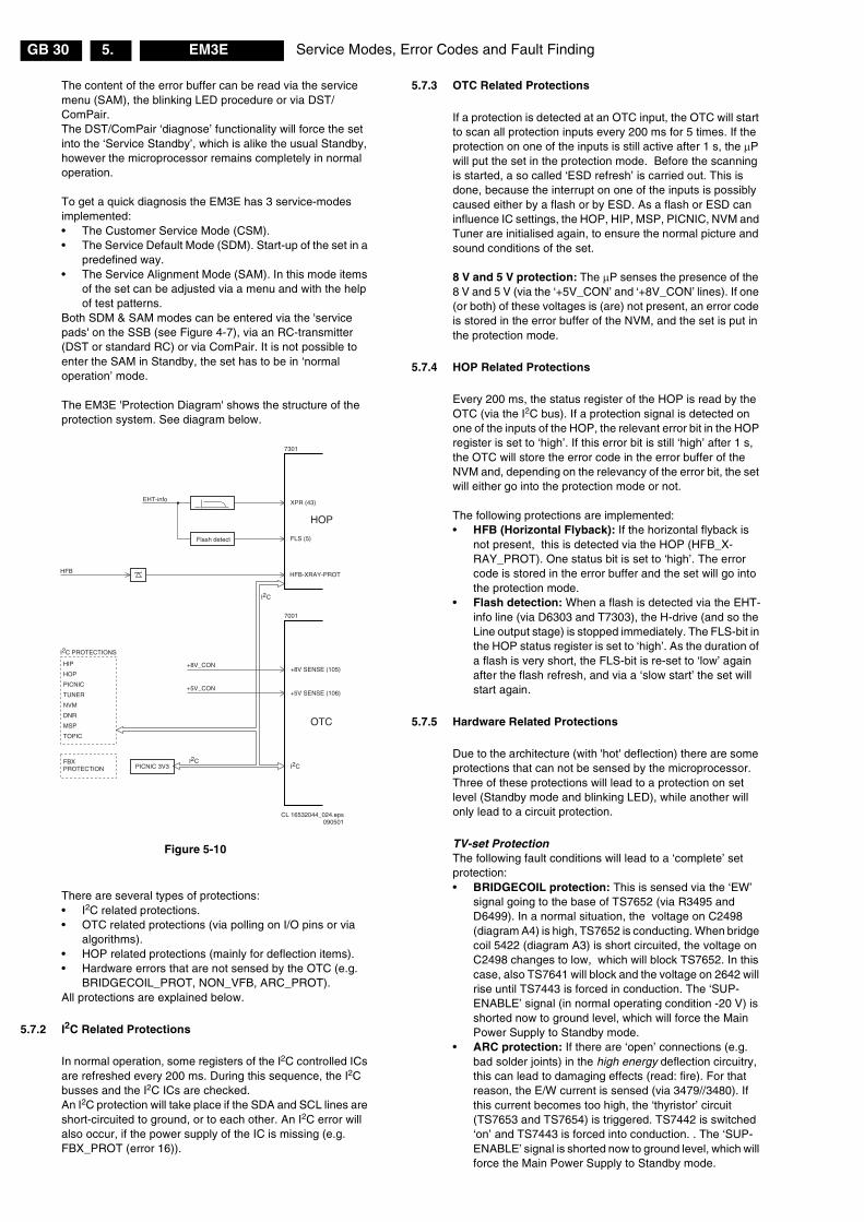
Service Modes, Error Codes and Fault FindingGB 30 EM3E5.
The content of the error buffer can be read via the servicemenu (SAM), the blinking LED procedure or via DST/ComPair.The DST/ComPair ‘diagnose’ functionality will force the setinto the ‘Service Standby’, which is alike the usual Standby,however the microprocessor remains completely in normaloperation.
To get a quick diagnosis the EM3E has 3 service-modesimplemented:• The Customer Service Mode (CSM).• The Service Default Mode (SDM). Start-up of the set in a
predefined way.• The Service Alignment Mode (SAM). In this mode items
of the set can be adjusted via a menu and with the helpof test patterns.
Both SDM & SAM modes can be entered via the 'servicepads' on the SSB (see Figure 4-7), via an RC-transmitter(DST or standard RC) or via ComPair. It is not possible toenter the SAM in Standby, the set has to be in ‘normaloperation’ mode.
The EM3E 'Protection Diagram' shows the structure of theprotection system. See diagram below.
Figure 5-10
There are several types of protections:• I2C related protections.• OTC related protections (via polling on I/O pins or via
algorithms).• HOP related protections (mainly for deflection items).• Hardware errors that are not sensed by the OTC (e.g.
BRIDGECOIL_PROT, NON_VFB, ARC_PROT).All protections are explained below.
5.7.2 I2C Related Protections
In normal operation, some registers of the I2C controlled ICsare refreshed every 200 ms. During this sequence, the I2Cbusses and the I2C ICs are checked.An I2C protection will take place if the SDA and SCL lines areshort-circuited to ground, or to each other. An I2C error willalso occur, if the power supply of the IC is missing (e.g.FBX_PROT (error 16)).
5.7.3 OTC Related Protections
If a protection is detected at an OTC input, the OTC will startto scan all protection inputs every 200 ms for 5 times. If theprotection on one of the inputs is still active after 1 s, the �Pwill put the set in the protection mode. Before the scanningis started, a so called ‘ESD refresh’ is carried out. This isdone, because the interrupt on one of the inputs is possiblycaused either by a flash or by ESD. As a flash or ESD caninfluence IC settings, the HOP, HIP, MSP, PICNIC, NVM andTuner are initialised again, to ensure the normal picture andsound conditions of the set.
8 V and 5 V protection: The �P senses the presence of the8 V and 5 V (via the ‘+5V_CON’ and ‘+8V_CON’ lines). If one(or both) of these voltages is (are) not present, an error codeis stored in the error buffer of the NVM, and the set is put inthe protection mode.
5.7.4 HOP Related Protections
Every 200 ms, the status register of the HOP is read by theOTC (via the I2C bus). If a protection signal is detected onone of the inputs of the HOP, the relevant error bit in the HOPregister is set to ‘high’. If this error bit is still ‘high’ after 1 s,the OTC will store the error code in the error buffer of theNVM and, depending on the relevancy of the error bit, the setwill either go into the protection mode or not.
The following protections are implemented:• HFB (Horizontal Flyback): If the horizontal flyback is
not present, this is detected via the HOP (HFB_X-RAY_PROT). One status bit is set to ‘high’. The errorcode is stored in the error buffer and the set will go intothe protection mode.
• Flash detection: When a flash is detected via the EHT-info line (via D6303 and T7303), the H-drive (and so theLine output stage) is stopped immediately. The FLS-bit inthe HOP status register is set to ‘high’. As the duration ofa flash is very short, the FLS-bit is re-set to ‘low’ againafter the flash refresh, and via a ‘slow start’ the set willstart again.
5.7.5 Hardware Related Protections
Due to the architecture (with 'hot' deflection) there are someprotections that can not be sensed by the microprocessor.Three of these protections will lead to a protection on setlevel (Standby mode and blinking LED), while another willonly lead to a circuit protection.
TV-set ProtectionThe following fault conditions will lead to a ‘complete’ setprotection:• BRIDGECOIL protection: This is sensed via the ‘EW’
signal going to the base of TS7652 (via R3495 andD6499). In a normal situation, the voltage on C2498(diagram A4) is high, TS7652 is conducting. When bridgecoil 5422 (diagram A3) is short circuited, the voltage onC2498 changes to low, which will block TS7652. In thiscase, also TS7641 will block and the voltage on 2642 willrise until TS7443 is forced in conduction. The ‘SUP-ENABLE’ signal (in normal operating condition -20 V) isshorted now to ground level, which will force the MainPower Supply to Standby mode.
• ARC protection: If there are ‘open’ connections (e.g.bad solder joints) in the high energy deflection circuitry,this can lead to damaging effects (read: fire). For thatreason, the E/W current is sensed (via 3479//3480). Ifthis current becomes too high, the ‘thyristor’ circuit(TS7653 and TS7654) is triggered. TS7442 is switched‘on’ and TS7443 is forced into conduction. . The ‘SUP-ENABLE’ signal is shorted now to ground level, which willforce the Main Power Supply to Standby mode.
XPR (43)
7301
7001
FLS (5)
HFB-XRAY-PROT
HOP
+8V SENSE (105)
+5V SENSE (106)
OTC
EHT-info
HFB
+5V_CON
+8V_CON
Flash detect
I2C
I2C PROTECTIONS
HIP
HOP
PICNIC
TUNER
NVM
DNR
MSP
TOPIC
I2CI2C
PICNIC 3V3FBXPROTECTION
CL 16532044_024.eps090501

Service Modes, Error Codes and Fault Finding GB 31EM3E 5.
• NON_VFB (No vertical Flyback) protection. If theframe stage generates no pulses, TS7641 will block.TS7443 is now switched ‘on’, which will lead to Standbymode. So in normal operation condition, TS7641 andTS7652 are conducting, while TS7443 is blocked.
Circuit ProtectionThe following fault condition will lead to a ‘partly’ setprotection:• PROT1 protection: When a DC-voltage (positive or
negative) is sensed on one of the loudspeaker outputs,the protection circuit (TS7704, 7705, 7706 and 7707),will put the IC7700 in Standby mode (via tri-state inputpin 6). For more details see chapter 9.
5.8 Repair Tips
5.8.1 Miscellaneous
The relay you hear when you switch the set 'on' (fromStandby or via the mains switch), is from the degaussingcircuitry. It is not used for switching the Power Supply (asdone in the MG-chassis).
Take care not to touch the ‘hot’ heatsink while disconnectingthe SSB, despite the fact that the mains cord is out of themains socket. There can still be an annoying rest-voltage onthe heatsink for a short while. This, because the dischargeresistors 3502 and 3503 (on the LSP between hot and coldpart) are not stuffed for Europe.Instead, discharge resistors 3066 and 3057 on the MainsSwitch panel are used, but because they are located beforethe Mains switch, they only discharge when this switch is‘on’.Advice: when you remove the SSB, disconnect the Mainscord, but keep the Mains switch ‘on’.
Do not try to measure on the SSB side, which is facing the‘hot’ heatsink. This is dangerous. Most service test points areguided to the ‘tuner’ side and are indicated by the ‘service’printing. Where the circuitry was too ‘crowded’ for thisprinting, you can find the correct location on the ‘test pointoverviews’ in this manual (chapter 6).
A very large part of the LSP is 'hot', such as:– the primary part of the Standby Supply,– the whole Main supply (except for the secondary Audio
supply),– and the complete deflection circuitry (so notice that the
deflection coil is hot !!).
5.8.2 Start-up Sequence
The start up sequence differs from other sets (e.g. MG-setsor EM2E-sets):1. When the set is switched ‘on’, the 5 and 8 V lines
(‘+5V_CON’ and ‘+8V_CON’) of the standby powersupply are activated.
2. After they are sensed by the OTC, the �P will address theHOP via the I2C-bus, to start the drive [1].
3. Via the ‘SUP-ENABLE’ signal, the Main Supply isswitched ‘on’ and will deliver the VBAT to the Linedeflection stage [2].
4. EHT generation is now started.5. The OTC will un-blank the picture.6. When you switch ‘off’ the set, this is done in a controlled
way via the POR signal [3].
Note: Standby is not directly achieved via the Standby line ofthe microprocessor, but indirectly via the HOP circuitry.
Figure 5-11
5.8.3 ComPair
This chassis does not have an IR transmitting LED (as in MG-sets). Therefore a ‘Service’ (ComPair) connector isimplemented at the rear side of the set, which is directlyaccessible (as in EM2E-sets). In addition to this, there is alsoa blinking LED procedure to show the contents of the errorbuffer.
When you use ComPair, you have the possibility to activatea ‘stepwise start-up’ mode. With this mode, you can initiatethe start-up sequence step by step. This also means that incertain steps, some protections are not activated. This issometimes very convenient during repair (see alsoparagraph 5.4.3).
5.8.4 Protections
There are ‘service pads’ implemented on the SSB (items4005 and 4006, outside the shielding), to force the set inSDM or SAM (see also Fig. 7 in Chapter 4). This will overrulethe processor-controlled protections, but not the hardwareprotections. This means, that the A/D-input protections (5and 8 V) and the I2C ‘not-acknowledging’ info from thefeature box (FBX) are overruled. Caution: When doing this,the service technician must know what he is doing, as it couldlead to damaging the set.
The ‘ARC’- and/or ‘BRIDGECOIL’ protection are hardly evertriggered, however:– When you suspect the ‘ARC’ protection, look for bad
solderjoints and smell. By interrupting resistor 3497, thisprotection is disabled (special attention needed !).
– When you suspect the ‘BRIDGECOIL’ protection, whichcan also be due to a too wide picture amplitude, shortenG and S of of the E/W MOSFET 7480. This will disablethe protection. You will now have a minimal horizontalamplitude. Re-align the horizontal amplitude in the SAMmenu and remove the G/S short of TS7480.
5.8.5 Main Supply
• The simplest way is, to replace the components of theMain Supply with repair kit (3122 785 90310)
• More detailed way:
RESET
5VCON
8VCON
8V
29
I2C BUS
5
17/39 OUT
HOP
CUTOFF(from CRT panel)
START/STOP
START/STOP
COLD
EHT-INFO
HOT
7131
71415V
8V
+11D
OTC
POR
POR7445
106 105
99 104
STANDBYlow 7131/41 closedhigh 7131/41 open
220 VAC
STBYSUPPLY
Vbat
SUP-ENABLE
MAINSUPPLY
PROT-SENSING
LINE DEFL.(BRIDGECOIL-PROT)(ARC-PROT)
FRAMEDEFL
(NON-VFB)
CL16532044_023.eps140501
1
3
2
Service Modes, Error Codes and Fault FindingGB 32 EM3E5.
– Replace FET 7504 and zener 6505.– Remove the SSB panel.– Short B and E of TS7529, in order to put the Main
Supply in ‘on’-mode (TS7529 is blocking then).Caution: To prevent that this will damage R3403and TS7443, first disable the HW-protection ofthe deflection circuit. Therefor short circuit C2642on the LSP (diagram A4)
– Attach a load of 500 � to VBAT capacitor C2515 (thesupply can not work without a minimum load).
– Use a variac, and slowly increase the VMAINS.Measure over sensing resistors R3514//15 if a nicesawtooth voltage becomes available.
– Also measure the VBAT . This may never exceed+141 V. If it does, there is something wrong in thefeedback circuitry (e.g. regulator 7506).
• Note: Be careful when measuring on the gate of FETTS7504. This circuitry is very high-ohmic and can easilybe damaged (first connect ground to measuringequipment, than measure the gate).
5.8.6 Standby Supply
The simplest way is to replace the components of theStandby Supply with repair kit 3122 785 90320.
5.8.7 Line Deflection
The simplest way is to replace the components of the LineDeflection circuitry with repair kit 3122 785 90330.
5.8.8 Frame Deflection
Caution: When the Frame Deflection circuitry is suspected,one must be careful. Because there is a DC-voltage on theframe deflection, the beam current could damage the CRTneck, leading to a defective CRT.
Best thing to do is:1. Interrupt the resistors 3403 and 3404 on the CRT panel
(diagram F), in order to remove the ‘filament’ voltagefrom the tube (no beam current, so no chance ofdestroying the CRT).
2. Interrupt resistor 3403 on the LSP (diagram A4) todisable the ‘SUP-ENABLE’ line.
3. Measure with a multimeter, or better with a oscilloscope,the functionality of the Frame stage.
4. After you’ve found the cause, exchange the defectivecomponent (e.g. TDA8177), and re-solder theinterrupted resistors.

Service Modes, Error Codes and Fault Finding GB 33EM3E 5.
Phenomenon Possible Cause Repair tipNo picture, no LED. Standby Supply defective. Measure circuitry (see diagram A2). Start at test-point A19.
When the Mains switch is ‘on’, this voltage must always be availableNo picture, no LED. Bad connection of SSB in
SIMM-connector.In case of a bad connection, it can happen that there is no picture, and that theStandby LED is not controllable. Re-place the SSB.
No picture, red LEDblinking at 3 Hz.
Set is in protection due tovarious causes. For errorcodes see error-code list.
You have no picture, so:- or you read the error buffer via ComPair- or you read the blinking LED information via ‘diagnose’-‘x’-‘ok’ on DST- or you read the error code sequence via ‘diagnose’-‘0’-‘ok’ with the DST.When you have found the error, check the circuitry related to the supply voltageand I2C-communication or the circuitry that triggers the protection.
No picture, red LEDblinking with code 6-6-6or 18-18-18.
No communication on slowI2C- or fast I2C-bus.
As processor cannot communicate with one of the 2 busses it the standby-ledspontaneously starts blinking 6-6-6… or 18-18-18….If in the error buffer somewhere is an error 6 or 18, these will have the highestpriority starting the mentioned blinking.Measure dependent of the error on the I2C-bus which device is loading the bus.(use I2C -overview)
No picture, red LEDblinking with code 1-1-1.
No communication on NVM-I2C bus to the µP.
As the µP cannot communicate with the NVM I2C bus, it spontaneously startsblinking 1-1-1. Note: when there is no access to the NVM, a lot of picturesetting can go wrong.
No picture, no sound.Set is making audiblesqueaking sound
Supply is possibly in hiccup-mode, which is audible via asqueaking supply transformer.
Possible causes:- VBAT is shorted (caused by short circuited line transistor 7421), or- Sound winding is shorted (amplifier is shortening the power supply lines),
or- D6514 is shorted (due to a too high VBAT).Remove excessive load, to see what causes the failure, or check feedbackcircuit. See repair tip ‘Main Power Supply’ (supply needs a minimal load).
No picture, no sound.Green LED works fine
Supply does not workcorrectly.
If e.g. VBAT is only about 90 V, it is possible that the regulator IC (7506) isdefective.
No RC-reception. RedLED does not echo RC-commands.
µP circuitry or RC-receiver isdefective.
In case the set does react on a local keyboard operation, you must check theRC-receiver circuitry (diagram E).
Relay (degaussing) isnot audible, when set isswitched from ‘off‘ or‘standby’ to ‘on’.
µP is not working correctly.When pin 115 is low, thedegaussing must beactivated.
Check RESET-circuitry on diagram B5. Check the level on pin 115 when youswitch the set ‘on’. Signal must be low initially and go to high after approx. 12 s.
No sound, only picture. Measure A7/A8 on diagramA1. Possibly the audioamplifier is defect (but notshorted), or the ‘soundenable’ line is high (diagramA5). Further, measure theaudio signal path (HIP-MSP-Switch ICs-Amplifier).
In ComPair, a beep test can determine where the signal stops (useloudspeakers or headphone).Possible cause is also the ‘PROT1’ protection (see diagram. A6). This is aloudspeaker DC protection, which the µP can not sense. Via circuitry7701/7707, this signal can put audio amplifiers 7700 and 7702 in standby mode(tri-state input). Warning: Find out, which amplifier is causing the problem,because it is possible, that the other one is OK.
No sound at headphoneoutput.
HP amplifier (7770), or thesupply to it, malfunctions.
Measure test points A64 to A67, and the supply line (+/- 16/19V) on diagramA7.
Picture is rotated. Rotation circuitry, or relatedsupply to it, malfunctions.
Measure test points A52 and A53 on diagram A5.
Picture is continuouslyswitching ‘off’ and ‘on’,showing heavy ‘switch’spots (set does not gointo protection).
200 V is missing on CRTpanel.
Probably a bad connection from LSP connector 1424 to CRT connector 1224(diagram F), or an interruption of the 200 V supply line (e.g. R3341 isinterrupted).
Picture is not sharp. Focus is possibly mis-alignedor SCAVEM-circuitry does notwork correctly.
Re-align the ‘focus’ potmeter on the Line Output Transformer, or check theSCAVEM circuitry on the CRT-panel (diagram F). It is also possible that theDAF circuitry is defective (see diagram I). Check the Vdc values.
Picture is notsynchronised.
The sync is derived in the HIPfrom xtal 1305 and/or 1308.
Maybe the crystals 1305 and/or 1308 are making a bad contact.
Picture is distorted. Check video-path in ServiceDefault Mode.
Investigate whether there is an error code present in the error buffer. In casethere is one, check the I2C-bus and/or supply lines (see overview supply lines).Measure and check signal path Tuner-HIP-PICNIC-HOP-RGB amplifier.In case it is a geometry issue, check opto-coupler 7482, OpAmps 7440/7450and the Frame circuitry alignments or a possible corrupted NVM (7011).
Picture with horizontalstripes.
Feature box processing ismalfunctioning
Check functionality of PICNIC (7709), FALCONIC (7726) and/or field memories(7714 and 7740). TS7726 and 7740 are suspected.
No menu, no OSD. Probably a defective µP. Measure test points B61to B64 on diagram B5.
No NextView (EPG). IC7012 defective or notpowered.
Check circuitry around IC7012.
No Teletext. IC7007 defective or notpowered.
Check circuitry around IC7007. Check also B61to B64 around µP on diagramB5.
Strange switch ‘off’behaviour
TS7445 possibly defective. Check, with a multimeter, whether transistor TS7445 is well functioning.
Various symptoms, dueto missing local supplyvoltage.
An interrupted fuse, NFR-resistor or connection.
When no symptom or error code leads you to a specific circuitry, use the supplylines overview (see chapter 6), for a quick scan of all supply lines.
CL 16532044_039.eps140501

Service Modes, Error Codes and Fault FindingGB 34 EM3E5.
Personal Notes:

Electrical Alignments GB 87EM3E 8.
8. Electrical Alignments
Index of this chapter:1. General alignment conditions.2. Hardware alignments.3. Software alingnments.4. Option settings.
Note: The Service Default Mode (SDM) and ServiceAlignment Mode (SAM) are described in chapter 5. Menunavigation is done with the 'CURSOR UP, DOWN, LEFT orRIGHT' keys of the remote control transmitter.
8.1 General Alignment Conditions
Perform all electrical adjustments under the followingconditions:• Power supply voltage: 230 VAC / 50 Hz (� 10 %).• Connect the set to the mains via an isolation transformer
with low internal resistance.• Allow the set to warm up for approximately 20 minutes.• Measure the voltages and waveforms in relation to
chassis ground (with the exception of the voltages on theprimary side of the power supply).Caution: never use the cooling fins / plates as ground.
• Test probe: Ri > 10 M�, Ci < 20 pF.• Use an isolated trimmer/screwdriver to perform the
alignments.
8.2 Hardware Alignments
Figure 8-1
8.2.1 Vg2 Adjustment
Method 1 (without oscilloscope)1. Activate the SAM.2. Select ‘Alignments’.3. Select the ‘General’ sub-menu.4. Set ‘Vg2 Test Pattern’ to ‘On’5. First turn the Vg2 potmeter on the LOT (see Fig. 8-1) to
the left (OSD feedback will show ‘Out high’).6. Turn the Vg2 potmeter slowly clockwise until you read ‘In
low’. This is the correct value.
Method 2 (with oscilloscope)In the frame-blanking period of the R, G and B signals appliedto the CRT, the ‘HOP’ video processor inserts a measuringpulse with different DC levels. Measure the black level pulseduring the vertical flyback at the RGB cathodes of the CRT.1. Go, via the MENU key, to the normal user menu, select
PICTURE, and set CONTRAST and BRIGHTNESS to 0.2. Activate the SAM.3. Connect the RF output of a pattern generator to the
antenna input. Test pattern is a 'black' picture (blankscreen on CRT without any OSD info).
4. Set the channel of the oscilloscope to 50 V/div and thetime base to 0.2 ms. Use external triggering on thevertical pulse (caution: use e.g. R3641 ,which is at the‘cold’ side!).
5. Ground the scope at the CRT panel (‘cold’ side) andconnect a 10:1 probe to one of the cathodes of thepicture tube socket (see diagram F).
6. Measure the cut off pulse during first full line after theframe blanking (see Fig. 8-2). You will see two pulses,one being the cut-off pulse and the other being the whitedrive pulse. Choose the one with the lowest value, this isthe cut-off pulse.
7. Select the cathode with the highest VDC value for thealignment. Adjust the Vcutoff of this gun with the SCREENpotentiometer on the LOT (see Fig. 8-1) to the correctvalue (160 � 3 VDC).
8. Restore CONTRAST and BRIGHTNESS to normal(CONTRAST= 63 and BRIGHTNESS= 34).
Figure 8-2
8.2.2 Focusing
1. Tune the set to a circle & crosshatch test pattern (use anexternal video pattern generator).
2. Choose picture mode ‘NATURAL’ with the ‘SMARTPICTURE’ button on the remote control transmitter.
3. Adjust the FOCUS 1 potentiometer (upper potmeter, seeFig. 8-1) until the horizontal and vertical lines at 1/4 fromeast and west, at the height of the centre line, are ofminimum width without visible haze.
4. Adjust the FOCUS 2 potentiometer (middle potmeter,see Fig. 8-1) until the horizontal and vertical lines at 1/4from north and south, at the height of the centre line, areof minimum width without visible haze.
CL 16532044_013.eps090501
Large Signal panel (LSP)
SS
B
V.SHIFTCINCH SCART
TUNER 3642
1502
5430
Focus 2Focus 1
ScreenVG2
LOT
Warning
All alignmentsare on hot-part !
A
B
C
0V Ref.CL 06532130_014.eps
131000
VCUTOFF [VDC]max.

Electrical AlignmentsGB 88 EM3E8.
8.3 Software Alignments
8.3.1 Introduction
With the software alignments, it is possible to align theGeometry, White Tone and Tuner IF settings.Put the set in the SAM (see chapter 5.2.2). The SAM menuwill now appear on the screen. Select, via 'Alignments', oneof the following submenus:
Figure 8-3
• General: Select this sub-menu to perform generalsoftware alignments.
• Normal Geometry: Select this sub-menu to performstandard geometry alignments.
• Super Wide Geometry: Select this sub-menu to performgeometry alignments for the 'Panorama' position in 16:9sets (only valid for wide screen sets). Alignments can beperformed; however, it is better to set values asmentioned below.
• Options: Select this sub-menu to set the initialisationcodes of the set via text menu’s.
• Option Numbers: Select this sub-menu to set all optionsat once (expressed in two long numbers). The originalfactory settings are printed on a sticker that is placed onthe CRT (inside the set).
• Store: Select this sub-menu to store the performedalignments.
The alignments are explained below in the sequence of thesub-menu.
Note:• Once all alignments/settings have been completed the
item 'Store’ must be selected to record all the values inthe permanent memory of the set.
• If the Option codes have been changed and stored, theset has to be switched 'OFF' and 'ON' using the mainsswitch to activate the new settings (when switching viaStandby, the option code settings are NOT read by themicroprocessor).
• If an empty EAROM (permanent memory) is detected, allsettings are set to pre-programmed default values.
• A built-in test pattern can be called up in various sub-menus. The test pattern generator can be switched onusing the item 'Test pattern on/off'. The test pattern onlyappears AFTER the specific alignment has beenselected. The test patterns are generated by theTeletext-IC (OTC).
8.3.2 'General' alignments
DriveMethod 1 (with colour analyser):1. Select ‘Test pattern’ and turn it ‘On’. You will get a white
block in middle of the image now.2. Select 'Cathode' and adjust the set to the correct light
output. This setting depends on the picture tube size and
brand. See table ‘Cathode parameter’ for the colouranalyser readings.
3. Select ‘Tint’ and set it to one of the three colourtemperatures (‘Cool’, ‘Normal’ or ‘Warm’)
4. Set the white levels according to the values in the table‘White levels’.
Figure 8-4
Figure 8-5
Method 2 (without colour analyser):1. Without having a colour-analyser one can set some
parameters. This is the next best solution. The setting-parameters are average values coming from production(statistics).
2. Select 'Cathode' and enter the value '15' (for all picturetubes).
3. Select ‘Tint’ and set it to one of the three colourtemperatures (‘Cool’, ‘Normal’ or ‘Warm’).
4. Set the ‘Red’, ‘Green’ and ‘Blue’ parameters according tothe values in table ‘Tint settings’.
5. ‘Red BL offset’: herewith the Black Level can be alignedvery precise. Default value is 7.
6. ‘Green BL offset’: herewith the Black Level can bealigned very precise. Default value is 6.
Figure 8-6
Luminance delaysWith this alignment you place the luminance informationexactly on the chrominance information (brightness ispushed onto the colour). Use a colour bar/grey scale patternas test signal.• Lum. Delay Pal: Apply a PAL colour bar/grey scale
pattern as a test signal. Adjust this parameter until thetransients of the colour part and black and white part ofthe test pattern are at the same position.
• Lum. Delay Secam: Apply a SECAM colour bar/greyscale pattern as a test signal. Adjust this parameter untilthe transients of the colour part and black and white partof the test pattern are at the same position.
• Lum. Delay Bypass: apply a NTSC colour bar/greyscalepattern as a test signal. Adjust this value until thetransients of the colour and black & white part of the testarea are at the same position.
EHT compensationFixed setting: 5
A l i g n m e n t s
G e n e r a l >N o r m a l G e o m e t r y >S u p e r W i d e G e o m e t r y >O p t i o n s >O p t i o n N u m b e r s >S t o r e >
CL 16532044_040.eps150501
��������������
�� �������������������
���������
��������� �
CL 16532044_090.pdf120601
������������
���� ����� ���
� �� ��� � �
! ��" ��� ���
#$%&'�()* � �" +
CL 16532044_091.pdf120601
������������
δδδδ����� ����� δδδδ����
� , �" -�
� �
� -� � ,��
CL 16532044_092.pdf120601

Electrical Alignments GB 89EM3E 8.
Soft clipperFixed setting:Pwl + 0%
Luma gainFixed setting:1
IF AFCSupply, via an external video generator (e.g. PM5518), a TVsignal with a signal strength of at least 1 mV and a frequencyof 475.25 MHz. Use system BG if possible, otherwise matchthe system of your generator with the received signal in theset.
Alignment procedure:1. Go to the 'Installation' menu.2. Select 'Manual installation'.3. Tune the TV-set to the system and frequency described
above via 'Search' - '475' - 'OK'.4. If the frequency, showed in the line 'Fine tune', is
between 475.18 MHz and 475.31 MHz, you don't need tore-adjust the ‘IF AFC’.
5. If not, adjust the frequency in the 'Fine tune' line to475.25 MHz and 'Store' the program (this is veryimportant because this will disable the AFC algorithm).
6. Now go to the SAM and select 'Alignments' - 'General' -'IF AFC'.
7. During the 'IF AFC'-parameter adjustment, one can seeOSD feedback in the top of the screen. This OSDfeedback can give 4 kind of messages:
Figure 8-7
The first item (‘In’ or ‘Out’) informs you whether you are in orout the AFC-window.The second item (‘High’ or ‘Low’) informs you about whetherthe AFC-frequency is too high or too low.1. First you must align the 'IF AFC'-parameter such that you
come into the AFC-window (= 'In')2. Then you must look for the point where the 'IF AFC'-
parameter changes from ‘High’ to ‘Low’. This level is thevalue you are looking for.
3. After adjustment, 'Store' the value.4. Now return to the 'Installation' menu.5. Select 'Manual Installation' - 'Search' - '475' - 'OK' and
'Store'. This will set the AFC 'on' again.
Service tip: If you do not trust the frequency accuracy of yourservice generator, connect it to a ‘good’ TV set and check itwith the 'Fine tune'-line.
Tuner AGC1. Set the external pattern generator to a colour bar video
signal and connect the RF output to the aerial input. Setthe amplitude to 10 mV and set the frequency to 475.25MHz.
2. Connect a DC multimeter between pin 1 and theshielding of the Tuner (item 1200 on the LSP).
3. Adjust the ‘TUNER AGC’ value (default value is 25) withthe LEFT/RIGHT cursor keys until the voltage at pin 1 ofthe tuner lies between 3.8 and 2.3 V.
4. ‘Store’ the alignment.
Blend intensityUse this alignment when you replace the microcontroller orthe HOP. It aligns the level of transparency of the menu-picture blended into the main-picture.1. Position the BRIGHTNESS, CONTRAST and COLOUR
setting in the middle position (picture-menu).2. Apply a signal with a 100 % white video-pattern.3. Connect an oscilloscope to pin 8 of connector 1298 of the
CRT panel and measure the Red output level.4. Align the 'Blend intensity' parameter such, that the
blended signal is 65 % of the black-white amplitude. Inpractice this is about 1.3 V (blended signal) versus 2 V(full white signal).
5. The parameter can be adjusted in between 0 and 31.
Adjust Peak White LimiterEnter value ‘4’ for all picture tubes.
Vg2 Test PatternIn this sub-menu, you can turn ‘On’ the OSD feedback for theVg2 alignment (see chapter 8.2.1).
8.3.3 'Normal Geometry' alignments
IntroductionUse for all geometry alignments, an external patterngenerator with a geometry pattern (e.g. crosshatch).See figure below for the correct alignments.
Figure 8-8
Warning: The use of the 'Internal Test Pattern' will, at thismoment, lead to a mis-alignment of the picture geometry. Souse an external generator with a geometry pattern (e.g.
� �!"����" � �!#�$����%���&��#�����
./0 1234
56 1234
In Low
./0 ;<=
CL 16532044_093.pdf120601
CL 16532044_022.eps140501
1
2
3
4
5
6
7
8
9
10
11
12
VERT. SLOPE
VERT. SHIFT
VERT. AMPLITUDE
V.S-CORRECTION
HOR. SHIFT
HOR. AMPLITUDE
E/W PARABOLE
UPPER E/W CORNER
LOWER E/W CORNER
E/W TRAPEZIUM
HOR. PARALLELOGRAM
HOR. BOW

Electrical AlignmentsGB 90 EM3E8.
crosshatch) for a correct geometry alignment. Use the'Internal Test Pattern' only for the 'Vertical slope' alignment.
V. slopeThis alignment is meant to align the zero crossing of theframe deflection to the mechanical middle of the picture tube.1. Set 'Test Pattern’ to ‘On' (read warning above).2. Set the 'V. S-correction' value to ‘0’ all sets (the
boundary-stripes of the test pattern should be positionedon the edge of the picture tube).
3. Align ‘V. slope’ (when aligning, the lower half of thepicture is blanked) such, that the middle line of the testpattern is matched with the edge of the pattern transientin the middle of the picture.
4. Push the 'MENU' button to return to the previous menu.
Vertical alignment1. Use 'V. amplitude' to align the vertical amplitude so that
the entire test pattern is visible.2. Set 'V. shift' to value ‘32’.3. Connect a voltmeter (VDC) between R3624 and ‘hot’
ground.4. Adjust the DC voltage to ‘0’ with potmeter R3642.5. Use 'V. shift' again to align the test pattern vertically in the
middle.6. Repeat the the alignment if necessary.
Horizontal alignment1. Use 'H. amplitude' to align the horizontal amplitude so
that the entire test pattern is visible.2. Use 'H. shift' to align the picture horizontally in the
middle.3. Repeat the 'H. amplitude' alignment if necessary.
Note: In case the horizontal linearity in wide-screen mode isout of tolerance, add a ‘DC-shift correction’ panel (3104 32806230) to connector 1419 of the DAF-panel [ I ]. Be sure toswitch ‘off’ the set first.On the DC-shift panel, cut diode 6433 for correction to theright or diode 6432 for correction to the left.Caution: never plug in a not pre-aligned module in a set !!!
East/west alignment1. Use 'East/West Parabola' to align the vertical lines until
straight.2. Use 'Upper East/West corner' to align the vertical lines in
the upper corners until straight.3. Use 'Lower East/West corner' to align the vertical lines in
the lower corners until straight.4. Use ‘East/West Trapezium’ to align for a rectangular.5. Use 'Horizontal Parallelogram’ to align for straight
vertical lines if necessary.6. Use ‘Horizontal Bow' to correct the E/W parabola such,
that it becomes symmetrical. Default value is ‘31’.7. Repeat steps 1 to 6 if necessary.
8.3.4 'Super wide geometry' alignments (only for widescreensets)
Note: The header of this paragraph and also the menu’s aresomewhat misleading. We only need to set the followingvalues (if the normal geometry alignment has beenperformed correctly):1. For ‘V. shift’ use the default value 33.2. For ‘V. amplitude’ use the default value 25.3. ‘V. S-Correction’, enter value of 'normal geometry'
alignment.4. ‘H. amplitude’, enter value of 'normal geometry'
alignment subtracted by 1.5. ‘East/west Parabola’, enter value of 'normal geometry'
alignment.
8.4 Option Settings
8.4.1 Introduction
The microprocessor communicates with a large number ofI2C ICs in the set. To ensure good communication and tomake digital diagnosis possible, the microprocessor has toknow which ICs to address. The presence / absence of thesespecific ICs (or functions) is made known via the optioncodes.
You can set the ‘hardware related’ options via the SAM -‘Alignments’ - ‘Options’ or ‘Option Numbers’ menu.You can set the ‘software related’ options via the SAM -‘Dealer Options’ menu .
After you have changed the option(s), save them via the'Store' command.
The new option setting is only active after the TV is switchedOFF and ON again via the mains switch (the EAROM is thenread out again).

Electrical Alignments GB 91EM3E 8.
8.4.2 Options
Select this sub-menu to set the initialisation codes (= options)of the set via text menu’s.
Figure 8-9
Menu-item Subjects Options Physically in the set
Aux type None Feauture not present.Yes Text Dual Screen present
Dual screen/PIPText Dual Screen
No Text Dual Screen not presentYes Teletext presentTXTNo Teletext not presentYes NextView setNextView presentNo NextView not setFlashram Flash-RAM present
Teletext/EPG
NextView typeNo Flashram Flash-RAM presentYes Easylink Plus setCommunication Easylink PlusNo Easylink Plus not set4:3 4:3 picture tubeCRT Type16:9 16:9 picture tubeYes Frame rotation circuitry present (diagram A5)Picture RotationNo Frame rotation circuitry not presentYes Dynamic focus (DAF) present (diagram I)Dynamic focusNo Dynamic focus (DAF) not presentYes
Picture Tube
One Point ControlNoEco PROZONIC not presentProzonic PROZONIC presentFalconic FALCONIC present
Featurebox type
1050i/1250i Progressive scan mode2Field memories3Yes Lightsensor presentLightsensorNo Lightsensor not presentYes PALplus module presentPALplusNo PALplus module not presentYes Not valid for EuropeCombfilterNoYes LTP presentPicture improvementNo LTP not presentYes PICNIC presentPicnicNo PICNIC not presentYes In normal operation: YesPicnic AGCNo During ‘Drive’ alignments: NoYes
Video repro
Signalling bitsNoYes 3rd EURO connector present (diagram H)External 3No No 3rd EURO connector presentYes 4th EURO connector present
Source Selection
External 4No No 4th EURO connector presentNoneDolbyPro LogicCorded Passive surroundbox presentVirtual Virtual Dolby (without rear speakers)
Rear speakers
Cordless Active surroundbox presentFL9 Monitor Modern design with only tweeters at both sides (monitor look)FL9 DAS Modern design with full range speakers at both sides
Acoustic system
FL12 Soft design with full range speakers at both sidesYesVirtual DolbyNoOn Automatic Volume Limiter on
Audio Repro
AVLOff Automatic Volume Limiter offYes Heatsink present on CRT/SCAVEM panel (diagram F)Heatsink PresentNo Heatsink not present on CRT/SCAVEM panel (diagram F)UV1316
Miscellaneous
Tuner typeTEDE9
CL 16532044_041.eps150501

Electrical AlignmentsGB 92 EM3E8.
8.4.3 Option numbers
Select this sub-menu to set all options at once (expressed intwo long numbers).
An option number (or ‘option byte’) represents a number ofdifferent options. When you change these numbers directly,you can set all options very fast. All options are controlled viaeight option numbers.
When the EAROM is replaced, all options will require a re-setting. To be certain that the factory settings are reproducedexactly, you must set both option number lines. You can find
the correct option numbers on a CRT sticker inside the TVset.
Example: The CRT sticker in the 32PW8870 gives thefollowing option numbers:04866 04384 08001 0001612407 00001 00000 00071The first line indicates the hardware options 1 to 4, thesecond line is reserved for the software options.Every 5-digit number represents 16 bits (so maximumnumber can be 65536 if all options are set).
When all the correct options are set, the sum of the decimalvalues of each Option Byte (OB) will give the option number.
Figure 8-10
OB Bit Option name Settings (given in decimal values) Option number0123
Cabinet 0 = FL6 (n/a)2 = FL8 (n/a)4 = FL9 Monitor6 = FL11 (n/a)
1= FL7 (n/a)3 = FL9 DAS5 = FL10 (n/a)7 = FL12
0
6 AVL 0 = Off 64 = On
Sum OB0
1 Sum OB12 0 CTI 0 = Off 1 = On Sum OB2
0 Auto TV 0 = Off 1 = On12
Auto Store Mode 0 = None4 = TXT Page
2 = PDC/VPS6 = PDC/VPS/TXT Page
34 Picture Mute 0 = Off 16 = On5 Demo 0 = Off 32 = On6 Virgin 0 = Off 64 = On
12 TXT Preference 0 = TOP 4096 = FLOF
3
13 TXT Region 0 = East 8192 = West
Sum OB3
02 China IF 0 = Off 4 = On3 Tuner 0 = Philips 8 = Alps4 TXT 0 = Off 16 = On
4
5 China TXT 0 = Off 32 = On
Sum OB4
0 EXT3 0 = Off 1 = On1 EXT4 0 = Off 2 = On
45
Dual Screen 0 = None32 = Dual Screen
16 = PIP
6 TXT/EPG/DS 0 = Off 64 = On7 Aux. Headph. Sound 0 = Off 128 = On8 Aspect Ratio 0 = 4:3 1 = 16:99 Tilt 0 = Off 512 = On10 DAF 0 = Off 1024 = On11 One Point Control 0 = Off 2048 = On12 Heat Sink 0 = Off 4096 = On13
5
14 Home Cinema 0 = Off 16384 = On
Sum OB5
01 Dolby ProLogic 0 = Off 2 = On2 Virtual Rear Spkrs 0 = Off 4 = On3 Cordless Rear Spkrs 0 = Off 8 = On4 Dolby Digital 0 = Off 16 = On5 Virtual Dolby 0 = Off 32 = On
8 P50 Easylink 0 = Off 256 = On
12 EPG 0 = Off 4096 = On
6
13 EPG Type 0 = Type 2 8192 = Type 2C3
Sum OB6
012
Featurebox 0 = Eco2 = Melzonic (n/a)
1 = Prozonic3 = Falconic
3 Comb Filter 0 = Off 8 = On4 PALplus 0 = Off 16 = On5 Field Memories 0 = 2 memories 32 = 3 memories6 Light Sensor 0 = Off 64 = On7 Luma Trans. Proc. 0 = Off 128 = On8 PICNIC 0 = Off 256 = On9 PICNIC-AGC 0 = Off 512 = On1011 LNA 0 = Off 2048 = On12 WSS 0 = Off 4096 = On
7
13 Time Constant 0 = Normal 8192 = Fast
Sum OB7
CL 16532044_042.eps150501

Electrical Alignments GB 93EM3E 8.
8.4.4 Dealer Options
Menu name Subjects Opt ions Physically in set
Yes CTI enabledPicture CTINo CTI disabledYes Blue mute active in case no picture detectedBlue MuteNo Noise in case of no picture detectedYes TV starts up once with language selection menu after mains
switch on for the first time (virgin mode)Virgin Mode
No TV does not starts up once with language selection menu aftermains switch on for the first time (virgin mode)
None Autostore mode disabled (not in installation menu)PDC-VPS Autostore mode via ATS (PDC/VPS) enabledTXT page Autostore mode via ACI enabled
Auto Store Mode
PDC-VPS-TXT Autostore mode via ACI or ATS enabledYes Demo menu enableDemo Menu EnableNo Demo menu disableYes Auto TV mode enabled
Personal
Auto TVNo Auto TV mode disabledTOP Preference to TOP TeletextTXT PreferenceFLOF Preference to FLOF TeletextWest TXT characters for non -/58 sets
Teletext
East/West TXTEast TXT characters for -/58 sets
CL 16532044_043.eps150501

Circuit Descriptions and Abbreviation ListGB 94 EM3E9.
9. Circuit Descriptions and Abbreviation List
Index of this chapter1. Introduction2. Block diagram3. Power supply4. Control5. Tuner & IF6. Video: High-end Input Processor7. Video: Feature box8. Video: High-end Output Processor9. Synchronisation10. Horizontal deflection11. Vertical deflection12. Audio13. Teletext / NexTView14. CRT / SCAVEM / Rotation15. Software related features16. Abbreviation list
9.1 Introduction
The EM3 Europe is a higher specified chassis as the EM2Europe. EM stands for Eco-MG, 3 for an indication that thisset is higher specified as the EM2E. So EM2E is a knownchassis with Digital Scan, EM3E is set with Natural Motion,EM4E will be the EM3E set inclusive a Digital Receptionboard. -Differences between the EM3E versus EM2E:– the start-up method is much more simple (no POR-bit
anymore)– the set has an advanced Standby Power Supply,
including MOSFET-switches for making Semi-standby(needed for Easylink and digital reception in future)
– added features as Natural Motion, EPG, LTP andupgraded Auto-TV
– the sound amplifiers have symmetrical supply voltagesnow. The IC is changed from TDA2616 to TDA7490(class-D amplifier, needing very little cooling)
– the vertical amplitude hardware alignment is changed toa software alignment via the SAM menu
– the vertical shift alignment is split into a hardware and asoftware alignment (needed due to spread)
– the Frame drive signals from the HOP are symmetrical.
The architecture consist of a conventional large signal panel(LSP) and a small signal board (SSB) module, placed into aso called SIMM-connector (Standard Interface, 80 pins).
The LSP is built up very conventional, with hardly any surfacemounted components on the copper side. Similar with theEM2E (but different as with the MG-chassis), the EM3E LSPhas a very large 'hot' part, including both deflection coils.
The SSB is a high tech module (2 sides reflow technology,full SMC) with very high component density and completeshielding for EMC-reasons. Despite this, it is designed insuch a way, that repair on component level still is possible.To achieve this, attention was paid to:• The position of service test lands: most of them are at the
Tuner side.• Accessibility (Tuner side). If there are still problems with
the accessibility, one can order an extension board (seeparts list).
• Clearance around surface mounted ICs (for replacing).• Detailed diagnostics and fault finding is possible via
ComPair.
Attention: During the first 4 to 6 months of production, theEM3E set-software will be integrated into a Flash-RAM onthe SSB. After that period, a Mask-ROM will be used. WhichIC is used is not of interest for Service, however for bothsolutions it means that Service Workshops must be equipped
with dedicated (de) solder equipment for exchanging theseICs.In case one must replace a Flash-RAM or a Mask-ROM in thefield, the Dealer will receive always an up-to-date Flash-RAM.
Warning: Be aware that half of the LSP-circuitry is 'hot',including the deflection coils.

Circuit Descriptions and Abbreviation List GB 95EM3E 9.
9.2 Block Diagram
Figure 9-1
The Tuner (item 1200) is a PLL tuner and delivers the IF-signal, via audio & video SAW-filters, to the HIP (High-endInput Processor). The HIP has the following functions:• IF modulation.• Video source- and record select.• Colour decoder.• Synchronisation.
Three SCART-connectors can be used:– SCART1 is fully equipped,– SCART2 is meant for VCR. Pin 10 is used for Easylink
and there is a possibility for Y/C in. The CVBS-out on pin19 is meant for WYSIWYR (What You See Is What YouRecord).
– SCART3 is a CVBS and audio L/R input.
The HIP delivers YUV and sync signals to the PICNIC. ThisIC takes care of:• Analogue to Digital conversion and vice versa.• 50 to 100 Hz conversion.• Panorama mode.• Noise reduction.• Dynamic contrast.
The ‘2fH features’-block in the diagram gives several options:– for Digital Scan the PROZONIC is required– for Natural Motion the FALCONIC is required.
After the PICNIC the, now 100 Hz, YUV- and H/V-signals arefed to the HOP (High-end Output Processor). This IC handlesthe video control and geometry part. The RGB-signals forTXT/OSD (from the �P) are also inserted via the HOP. Thevideo part delivers the RGB signals to the CRT-panel and the
geometry part delivers the H-drive, V-drive and also a drive-signal for rotation.
Both deflection circuits are 'hot' and located on the LSP. Theyare driven by the HOP. To make a galvanic separation, theLine Drive is driven via transformer 5410 and the FrameDrive via transformer 5621.The horizontal output stagegenerates some supply voltages and the EHT-, focus- andVg2-voltages.
The RGB amplifiers on the CRT-panel are integrated in oneIC and are supplied with 200 V from the LOT.The SCAVEM circuit modulates transitions of the Luminance(Y) signal on the horizontal deflection current, giving asharper picture.
The sound part is built around the MSP34xx (Multi-channelSound Processor) for IF sound detection, sound control andsource selection. Dolby decoding is also done by the MSP.Amplification is done via a ‘class D’ integrated poweramplifier IC, the TDA7490.
The microprocessor, called OTC (OSD, Teletext and Control)takes care of the analogue TXT input- and output processing.The OTC, ROM and RAM are supplied with 3.3 V, which isderived from the +5V2STANDBY.The NVM (Non Volatile Memory) is used to store the settings,one Flash-RAM contains the set software, the other Flash-RAM (7012) is for EPG and the DRAM is used for storing theTeletext pages.
In EM3E there is a separate Standby Supply, in order toreduce the Standby power consumption. During Standby, the
CL 16532044_014.eps160501
VERT
HORZ
ROTATION
CRT+
SCAVEM
SCAVEM
RGB
TDA9330TDA9178
HIPIFFILTER
TUNER
EXTI/O
TOPCNTRL
KEYBRD
POWERON/OFF
TDA932XSAWUV13XX
PICNIC
(FBX)
SAA4978
RGB
TILT
COLD HOT
HFB
FRAMEDRIVE-
FRAMEDRIVE+
CVBS-TXT
VIF
SIF
IF
SC
E/W
YUV
HDHA/ VA
E/W
FLASHRAM (EPG)
NVM(PROGRAM)
DRAM(TXT)
FLASHRAM (SW)
OTC(µP)
SAA5801
MSP
MSP34XX TDA7490
VIDEO
AUDIO
IRRECEIVER
SUPPLY 5V2 STANDBY
VBAT (141V)
VSOUND (+/-16V)
EHT
180V
VTUN
+11V
+8V
+5V
SIF
AM
TDA7490
NJM4556
L/R
HP
L/R
HP
SW/C
RGB-TXT
HFB
VD100
HD100
YUV100
VSYNC
VSYNC
HOPTOPIC
2fHfeat
MAINS

Circuit Descriptions and Abbreviation ListGB 96 EM3E9.
Main Supply is switched ‘off’ (via TS7529). A relay (1550) isused to switch the Degaussing circuit. It is switched ‘on’ afterset start-up and switched ‘off’ by the �P after 12 s.The Main Supply, an SMPS that is based on the 'down-converter' principle, generates the 141 V (VBAT) and the +/-16 V for the audio part. Difference with former MG-sets is thatVBAT is not mains isolated ('hot') and is alignment free.
9.3 Power Supply (diagram A1 & A2)
The power supply has a number of main functions:• Mains harmonic filter.• Degaussing picture tube.• Standby power supply.• Main supply.
9.3.1 Mains Harmonic Filter (diagram A1)
Figure 9-2
The mains harmonic filter has 2 functions: to prevent thathigh frequency signals (harmonics) are transferred into themains and to protect the set from lightning damage.
C2507 prevents that the high frequency signals, generatedby the set, are conveyed into the mains (it forms a short-circuit).
In case of a lightning surge between the 2 phases (differentialmode) the energy is immediately bled away through the VDR(R3509) to the other phase.In case of a lightning surge on both phases of the mains inrelation to the aerial earth, the filter acts as a high resistance(UEMK=L * dI/dt), as a result of which the voltage across coilL5503/04 increases. A spark gap (1590) prevents that thevoltage increases too much, which would lead to a damagedcoil. When ignited, the current will be discharged via thisspark gap.Resistor R3500 is used for limiting the inrush-current.
9.3.2 Degaussing (diagram A1)
The 5V2 is present, as soon the set is switched 'on' via themains switch. As the ‘DEGAUSSING’ signal from theprocessor (OTC) is ‘low’, transistor 7528 will conduct andrelay 1550 is activated. Initially a considerable current willflow, via PTC 3516, through the degaussing coil. The PTCwill heat up, resistance will rise and the current will decayrapidly. The OTC makes the ‘DEGAUSSING’ signal ‘high’after 12 s, which will switch the relay ‘off’.
9.3.3 Standby power supply (diagram A2)
PrincipleThis power supply is of a SOPS type (Self-Oscillating PowerSupply) and is regulated by the controlled switching of anoscillator. It uses the so-called 'Flyback' principle:
Figure 9-3
• After closing switch 'S', the current ID will increase linearin time. The magnetic energy in the primary coil is directlyproportional with the self-inductance of the coil andcurrent ID (thus with the time the switch is closed). Thevoltage polarity at the secondary winding is negative(due to different winding direction), meaning that diode Dwill block. Capacitor C will discharge via RL, UOUT willdecrease.
• Opening switch 'S' will generate a counter-e.m.f. in theprimary winding, trying to maintain current ID. Throughthis the polarity of the secondary voltage will inverse. Themagnetic energy, stored in the coil, will now betransformed to the secondary side. Diode D will nowconduct, capacitor C will be charged and OUT willincrease.
Implementation
Figure 9-4
To apply this on the EM3E (diagram A2): replace switch 'S'by FET TS7102, coil L by L5101/L5100, diode D by D6111and C by C2104.– Time interval t0 - t1: After switching ‘on’ the TV-set, the
gate of MOSFET TS7102 will be high (max. 15 V due tozener diode D6105). This will drive the FET intosaturation (UDS = 0 V). The DC-voltage UMAINS will betransposed across the primary winding of L5101 (3, 5),resulting in a linear increasing current through this coil.The voltage across the co-coupled coil (1, 2) is alsopositive and will keep the FET into conductivity viaC2101, R3103/3105/3102 and R3117 for some time.The self-induction of the coil and the magnitude of thesupply voltage (+375 V) determine the slope of theprimary current. The maximum current is determined bythe time the FET stays into conductance (t0 - t1). Thistime is directly determined by the voltage across R3108/
CL 16532044_020.eps140501
2507mains 3521
4M7
1501
1590
3501
9503
Mains harmonicdiversity
3551
21
34
V
9504
9504
+375V
-
- +
2516
2537
3500
5502
5511 or 5516
3
1
1
2
4
3
2
5503 or5504
96532156_020.eps210100
+
-
-
+
-
-+
+
RL
DId
Uout
C+
C+
375V
S
RL
DUout
375V
S
Isec
CL 16532044_019.eps160501
31031K
31051K
311322R
3124 6122
68R 3V9
RL
7101
610515V
31021K
311747R
312610K
312515R
7100
310447R
3101
STARTUP
V-START
10M
3127
5K6
3120
10R
31063107
1K 1K
21012n2
5102-13V
6111
6103
UMAINS
UOUT21042m2
D
SG
610615V
3114220R
2109 +2149
6108
3108//3118
+5V2
8
9
HOT COLD
GND-STB
GND-STB
2
1
5
3
2114
7102
610515V
10n
2102
10µ+
UA
UA
UD
UD
UMAIN
ISEC
IPRIM
IPRIM
ISEC
7104
t
t
t
t
N.Usec
ON OFF
t0 t1 t2
5101
3110
2R2
+375V
2111
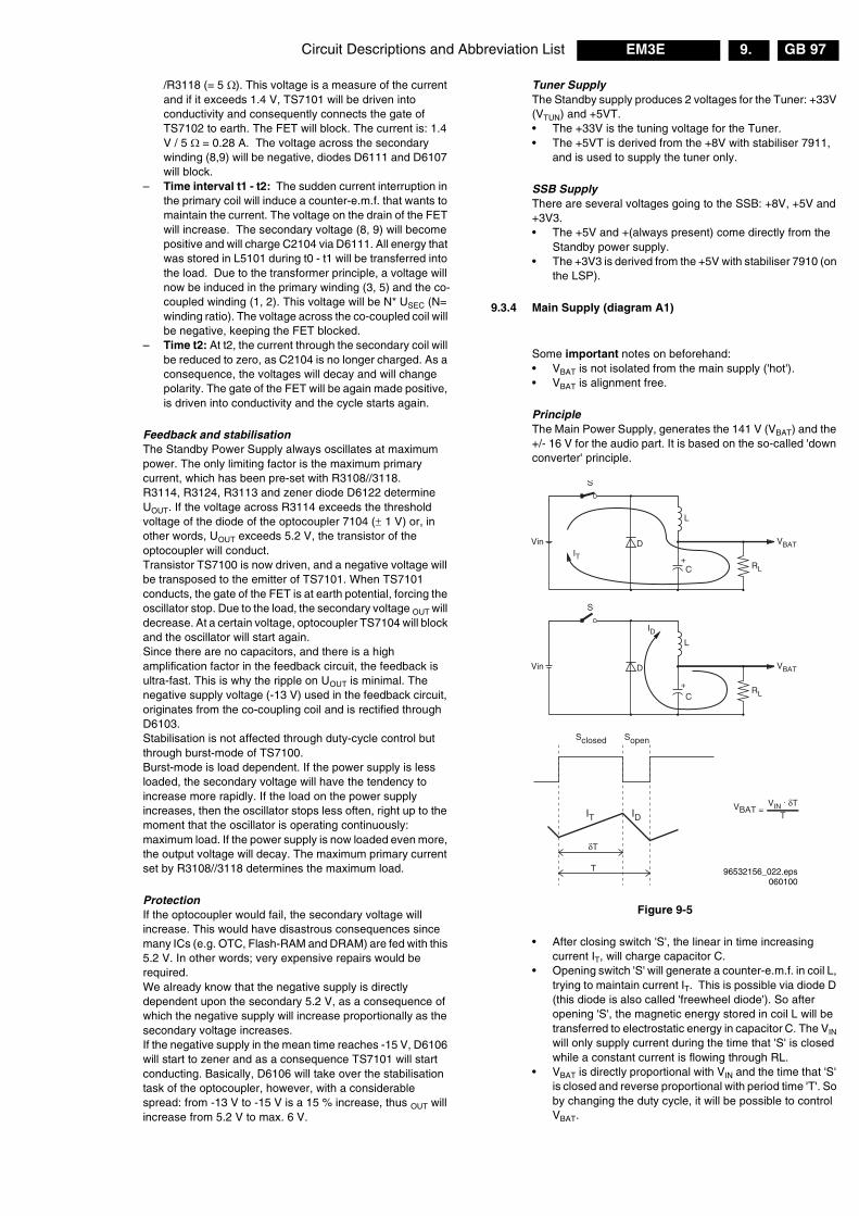
Circuit Descriptions and Abbreviation List GB 97EM3E 9.
/R3118 (= 5 �). This voltage is a measure of the currentand if it exceeds 1.4 V, TS7101 will be driven intoconductivity and consequently connects the gate ofTS7102 to earth. The FET will block. The current is: 1.4V / 5 � = 0.28 A. The voltage across the secondarywinding (8,9) will be negative, diodes D6111 and D6107will block.
– Time interval t1 - t2: The sudden current interruption inthe primary coil will induce a counter-e.m.f. that wants tomaintain the current. The voltage on the drain of the FETwill increase. The secondary voltage (8, 9) will becomepositive and will charge C2104 via D6111. All energy thatwas stored in L5101 during t0 - t1 will be transferred intothe load. Due to the transformer principle, a voltage willnow be induced in the primary winding (3, 5) and the co-coupled winding (1, 2). This voltage will be N* USEC (N=winding ratio). The voltage across the co-coupled coil willbe negative, keeping the FET blocked.
– Time t2: At t2, the current through the secondary coil willbe reduced to zero, as C2104 is no longer charged. As aconsequence, the voltages will decay and will changepolarity. The gate of the FET will be again made positive,is driven into conductivity and the cycle starts again.
Feedback and stabilisationThe Standby Power Supply always oscillates at maximumpower. The only limiting factor is the maximum primarycurrent, which has been pre-set with R3108//3118.R3114, R3124, R3113 and zener diode D6122 determineUOUT. If the voltage across R3114 exceeds the thresholdvoltage of the diode of the optocoupler 7104 (� 1 V) or, inother words, UOUT exceeds 5.2 V, the transistor of theoptocoupler will conduct.Transistor TS7100 is now driven, and a negative voltage willbe transposed to the emitter of TS7101. When TS7101conducts, the gate of the FET is at earth potential, forcing theoscillator stop. Due to the load, the secondary voltage OUT willdecrease. At a certain voltage, optocoupler TS7104 will blockand the oscillator will start again.Since there are no capacitors, and there is a highamplification factor in the feedback circuit, the feedback isultra-fast. This is why the ripple on UOUT is minimal. Thenegative supply voltage (-13 V) used in the feedback circuit,originates from the co-coupling coil and is rectified throughD6103.Stabilisation is not affected through duty-cycle control butthrough burst-mode of TS7100.Burst-mode is load dependent. If the power supply is lessloaded, the secondary voltage will have the tendency toincrease more rapidly. If the load on the power supplyincreases, then the oscillator stops less often, right up to themoment that the oscillator is operating continuously:maximum load. If the power supply is now loaded even more,the output voltage will decay. The maximum primary currentset by R3108//3118 determines the maximum load.
ProtectionIf the optocoupler would fail, the secondary voltage willincrease. This would have disastrous consequences sincemany ICs (e.g. OTC, Flash-RAM and DRAM) are fed with this5.2 V. In other words; very expensive repairs would berequired.We already know that the negative supply is directlydependent upon the secondary 5.2 V, as a consequence ofwhich the negative supply will increase proportionally as thesecondary voltage increases.If the negative supply in the mean time reaches -15 V, D6106will start to zener and as a consequence TS7101 will startconducting. Basically, D6106 will take over the stabilisationtask of the optocoupler, however, with a considerablespread: from -13 V to -15 V is a 15 % increase, thus OUT willincrease from 5.2 V to max. 6 V.
Tuner SupplyThe Standby supply produces 2 voltages for the Tuner: +33V(VTUN) and +5VT.• The +33V is the tuning voltage for the Tuner.• The +5VT is derived from the +8V with stabiliser 7911,
and is used to supply the tuner only.
SSB SupplyThere are several voltages going to the SSB: +8V, +5V and+3V3.• The +5V and +(always present) come directly from the
Standby power supply.• The +3V3 is derived from the +5V with stabiliser 7910 (on
the LSP).
9.3.4 Main Supply (diagram A1)
Some important notes on beforehand:• VBAT is not isolated from the main supply ('hot').• VBAT is alignment free.
PrincipleThe Main Power Supply, generates the 141 V (VBAT) and the+/- 16 V for the audio part. It is based on the so-called 'downconverter' principle.
Figure 9-5
• After closing switch 'S', the linear in time increasingcurrent IT, will charge capacitor C.
• Opening switch 'S' will generate a counter-e.m.f. in coil L,trying to maintain current IT. This is possible via diode D(this diode is also called 'freewheel diode'). So afteropening 'S', the magnetic energy stored in coil L will betransferred to electrostatic energy in capacitor C. The VIN
will only supply current during the time that 'S' is closedwhile a constant current is flowing through RL.
• VBAT is directly proportional with VIN and the time that 'S'is closed and reverse proportional with period time 'T'. Soby changing the duty cycle, it will be possible to controlVBAT.
96532156_022.eps060100
RL
IT
IT
VBATVin
S
C
L
RL
ID
ID
VBATVin
S
C
L
Sclosed Sopen
δT
VIN . δT
T
+
+
D
D
VBAT = T

Circuit Descriptions and Abbreviation ListGB 98 EM3E9.
Implementation
Figure 9-6
At start-up of the main supply, C2515 can be assumed asbeing a short-circuit. UAB will be 15 V (R3513, D6510) andUGS of the FET will be +5.4 V. The FET will be driven intosaturation (same as closing switch 'S' ). The drain-current willincrease linear in time. With other words: resistors R3513and R3518 will start the oscillator.The voltage across the co-coupled coil (4, 5) is also positiveand will keep the FET into conductivity.
The drive concept of the MOSFET TS7504 has changed(compared to the EM2E chassis). In EM2E, TS7502 was ahigh-voltage semiconductor, in EM3E it is changed to a low-voltage semiconductor. The added opto-coupler 7505 isused to bridge the different voltage levels.Via this opto-coupler, the DC-current through R3504 isinfluenced. The changed current through R3504, changesthe VBE of TS7502, which will influence the drive of MOSFETTS7504 (= switch ‘S’ in Fig. 5).
The sudden current interruption in the primary coil, willinduce a counter-e.m.f. that wants to maintain the current viathe 'freewheel' diode D6508. This current is linear decreasingin time and as it is also flowing through R3414//R3415,TS7502 will be blocked after a certain time period. The gateof the FET will be again made positive, is driven intoconductivity and the cycle starts again.
For safety reasons, transistor TS7530 is added as a back-upsolution for TS7502. If B-E of TS7502 is shorted, TS7530takes over its function.
Stabilisation of VBATThe output voltage VBAT is determined by: VBAT = VIN * TON /(TON + TOFF) = VIN * duty-cycle.To stabilise the output voltage, a feedback loop isimplemented, which will reduce TON when VBAT increasesand vice versa.
Via a voltage divider, excisting of (1 %) resistors R3507,R3510 and R3527, a voltage of 2.5 V (when VBAT = 141 V) isfed to the input of precision shunt regulator 7506. Thisregulator will conduct, a current will flow through the diodepart of the opto-coupler 7507. The base of TS7502 will nowbe set at a certain positive voltage. As this transistor switchesthe FET TS7504 on and off, this circuit can determine theduty-cycle.E.g. when the load increases, VBAT will decrease. As aconsequence, the input voltage of regulator 7506 willdecrease, resulting in a lower current. Via opto-coupler 7505
and transistor TS7502, TON of the FET is changed (willincrease). The output voltage VBAT will rise.If the load continues to increase, the regulator will block at acertain moment. TON will is now at maximum value. This isthe point where VBAT will go below 141 V and, at furtherincreasing load, is switched ‘off’ (the voltage across the co-coupled coil (4, 5) will decrease, due to the increasing load.Therefore the voltage on the gate of TS7504 comes belowthe threshold voltage. The supply switches ‘off’ and anaudible hiccuping can be heard).On the other hand when the load decreases, VBAT will rise. Asa consequence, the input voltage of TS7506 will also rise,resulting in a higher current. This changes the base voltageof TS7502, and through that the TON (will decrease) of theFET. The output voltage VBAT will be reduced.If, for instance, VIN will decrease (e.g. UMAINS is 180 V i.s.o.240 V), the slope of the drain-current will be flattened,through which the FET will be longer into conductance,keeping VOUT constant.If, for any reason, the stabilisation circuit might fail, the outputvoltage VBAT can never exceed 200 V (via D6514). D6514 willform a short-circuit, VBAT will drop and the set will switch off(this will result in an audible hiccuping of the supply).
Switch to ‘Standby’ (via RC)When the set is switched to 'Standby' mode via the RemoteControl, the Main supply is switched ‘off’ by the circuit aroundTS7529 (see diagram A1).During 'on'-state, the Main supply is fed with line pulses viathe ‘SUP-ENABLE’ line. They are rectified and smoothed viaD6517, D6516 and C2530 and fed to TS7529. Because theyare less than -13 V, this transistor is blocked. When thesepulses are stopped, TS7529 will be saturated and TS7502will switch ‘off’. This will switch ‘off’ the Main supply.
Set to ‘On’ (via ‘SUP-ENABLE’)Via the ‘STANDBY’ command from the OTC, the MOSFETS7141 and 7131 are switched ‘on’. When the +5V and +8V aresensed by the OTC, a command is given to the HOP to startthe drive (via I2C).When this is sensed via the ‘SUP-ENABLE’ line (at the baseof line transistor TS7421), the main supply is switched ‘on’via TS7529.
Audio SupplyThe pulses on the secondary winding of L5506 are rectifiedby D6535 (+16 V) and D6536 (-16V), and smoothed byC2542 and C2543.
D
A
SG
3518
3512
5V66515
3514//15
3522
3508
3511
7530
7504
7502650515V
6501
6510
15V
6535
7507
5506
COLDHOT
6536
6530
2503
35131503
2.5A
2512
+16V
-16V2513
141V
5
Vbat
141VVbat375V
7506
3506
3520
33k
3504
35072515
V - MAINS
CL 16532044_030.eps160501
B

Circuit Descriptions and Abbreviation List GB 99EM3E 9.
9.4 Control (diagram B5)
Figure 9-7
9.4.1 OTC
IntroductionThe SAA5801 (IC7001) is called the OTC (OSD, TXT andControl). In this IC, the microprocessor and the TXT-decoder(level 2.5) are integrated.Some of its functions are:• Set control.• TXT/OSD acquisition.• RGB-outputs to the HOP• Menu blending; for blending the contrast, software
controlled.• I/O-ports for I2C, RC5/RC6, LED, and service modes.• Error code generation.
Data StorageThe software for EM3E can be 2 MB (Megabyte).It is possible to store 1200 TXT pages in IC7007. This is aDRAM of 4 MBit and this IC is also used to store data of aworking set.For EPG a Flash-RAM (7012) is used.The Non Volatile Memory IC7011 is a 4 kB versionM24C32W6.
Power SupplyAll ICs in this part are supplied with 3V3. For this voltage a3V3 stabiliser is used (IC7005).
With the circuitry around TS7003 and 7004 (diagram B5) areset is generated to wake up the OTC (pin 74). During thisreset all I/O pins of the OTC are made ‘high’.
Via pins 105 and 106, the +8 V and the +5 V are sensed. Ifone of them is not present, the Main supply is switched ‘off’(set in protection and the red LED will blink at 3 Hz).The OTC will generate an error code to indicate what waswrong.
OSD/TXTThe horizontal (HD100) and vertical (VSYNC) sync pulses arealso fed to the OTC for stable OSD and TXT.The RGB-outputs (77/78/79) together with fading (pin 80) arefed to the HOP. The fading pin has a double function: it isused for making a transparent menu and as fast-blankingsignal for TXT.
9.4.2 I�C Busses
In the EM3E chassis with OTC-processor there are three I�Cbusses used:• Slow (max. 100 kHz) hardware I�C-bus (called I�C0),
used for the Tuner.• Fast (max. 400 kHz) hardware I�C-bus (called I�C1),
used for all ICs.• Separate short bus (called I�C3) for the Non Volatile
Memory (NVM), to avoid data corruption.
9.4.3 NVM
The Non Volatile Memory contains all set related data thatmust be kept permanently, such as:• Software identification.• Operational hours.• Error-codes.• Option codes.• All factory alignments.• Last Status items for the customer + a complete factory
recall.• Txt featuring (keeping habit watch data).• EPG data.
9.5 Tuner & IF (diagram A8 & B2)
The tuner is I2C controlled, and is capable of receiving off-air,S- (cable) and Hyperband channels:• Low 44 - 156 MHz• Mid 156 - 441 MHz• High 141 - 865 MHz
The tuning is done via I2C. The reference voltage on pin 9 is33 V. This voltage (VTUN) is derived from the secondary sideof the standby supply, via D6134 and R3116//R3115 and a33 V zener diode (D6200). The OTC, together with the HIP,controls the tuning procedure. There is also automaticswitching for the different video systems.
The IF-filter is integrated in a SAW (Surface Acoustic Wave)filter. The type of this filter depends on the receivedstandard(s). There are two SAW filters: one for filteringpicture-IF and a second one for sound-IF. An extra filter(5403), tuned at 40.4 MHz, is necessary for L/L’ sets (with 6.5MHz sound), to suppress the neighbour channel.
The output of the tuner is controlled via an IF-amplifier withAGC-control. This is a voltage feedback from pin 62 of theHIP to pin 1 of the tuner. AGC take-over point is adjusted viathe service alignment mode ’Tuner AGC’. If there is too muchnoise in the picture, it is possible that the AGC setting iswrong. It is also possible that the AGC-setting is mis-aligned,if the picture deforms with a perfect signal. Then the IF-circuitamplifies too much.
The video IF-signal is fed to pins 2/3 of the PLL-controlled IF-demodulator. The voltage controlled oscillator of the PLL is
CL 16532044_016.eps160501
SAA5801
P50-OUT
SEL_IN_2
STATUS SC3
FRONT DETECT
120
A0...A19 D0...D15
CVBS-TXT
7001
5
KEYBOARD 107
+5V 106
+8V 105
91/92
+3V3
113
+5V2 RESET
ON/OFF-LED
74
H, V 83,84
119
117
109
LIGHT SENSOR110
DEGAUSSING115
108
SEL_IN_1103
STANDBY104
POR99
RC5/RC6100
P50-IN97SDM
4006
96SOUND ENABLE95
RESET AUDIO94
RGB, BLENDING77,78,79,80
FRAME81
FLASHEPG
FLASH(SW)
DRAM(TXT)
EEPROMM24C32
NVM
TUNER UV13xx
SAM
4005
+3V3 +RESET
+3V3
+3V3
I2C3+3V3
I2C1
I2C085/86
87/88
slow
fastHIP
HOP
MSP 3415/3451/3411
FBX PICNIC
DNR MEMORY
TOPIC
NVM(PROG)
Circuit Descriptions and Abbreviation ListGB 100 EM3E9.
adjusted via the service menu ‘IF AFC’. If the alignment iscorrect, the displayed frequency in the installation menu isthe same as the applied frequency from a generator. Theexternal coil L5408 connected between pins 7/8 is used asreference.The demodulated IF-video signal is available at pin 10 of theHIP. In this video signal, there is a rest of the sound carrier,which is filtered out by the sound trap 1407.Then the signal is again fed to the HIP on pin 12, where thegroup delay is corrected, dependent on the standard that isreceived.The CVBS-signal is available at pin 13 for further processingin the set. Via TS7322, the signal is supplied to EXT1(monitor out) and again back into the HIP (pin 14) to thesource/record selection.
To realise Quasi Split Sound (QSS), the IF-signal is fed to theHIP on pin 63/64 via SAW-filter 1405. The FM (or AM for L-norm) -modulated signal is available on pin 5 and is fed to theaudio demodulator MSP34xx (7651).
9.6 Video: High-end Input Processor (HIP,diagram B2))
In the EM3E, the HIP TDA932xH is used, which contains thefollowing functions:• IF demodulation.• Group delay correction.• AFC signal generation, used to track drifting transmitters.• Sound carrier re-generation (SIF).• AM demodulation.• Sync acquisition, delivering HA and VA.• Switching off IF-filtering.
9.6.1 Inputs
The HIP has various inputs:• Full matrix switch with:
– 2 CVBS inputs– 2 Y/C (or additional CVBS) inputs– 1 CVBS front end input.
• Two RGB inputs and 2 status-inputs
The input signals from the Front I/O are fed to the HIP, andfront detection is fed to the OTC.• EXT1 is full SCART: thus CVBS and RGB. The RGB-
selection is done in the HIP.• EXT2 is meant for VCR and has therefore some
additional signals in relation to EXT1 but no RGB. EXT2has also the possibility for Y/C_in and Easylink-Plus(P50). Y_in is with pin 20 and Chroma in with pin 15.Easylink is handled via pin 10 of the SCART and this is abi-directional communication.
• EXT3 is meant for CVBS input only.
9.6.2 Outputs
One can select three, separate switchable, outputs:• 1 YUV-output, which is fed to the PICNIC• 2 CVBS outputs, one for Teletext Dual Screen and the
other for output to EXT2 to have WYSIWYR (What YouSee Is What You Record).
9.6.3 I/O Switching
The external signals are fed directly to the I/O part of the HIPwith status from pin 8 of SCART. On the HIP there are twostatus inputs available (pins 15, 17) with two voltage levels:• 4:3 -> 2.2 V• 16:9 -> 5.5 V
9.6.4 P50
Easylink supports the next features:• Signal quality and aspect ratio matching• One touch play• One touch text• Pre-set download• WYSIWYR• Automatic Standby
With Easylink-Plus (P50+) is added:• Country and language installation• System Standby• Intelligent set top box features• NexTView download• Timer record control• VCR control feature
9.6.5 Video Processing
The sandcastle-pulse of the HIP is not used forsynchronisation. The HOP will generate synchronisationsignal derived from the feature box (PICNIC) signals. If aVCR is connected, there is also an automatic correction forMacroVision. This is active for the external sources and thepre-sets 0, 90-99.The HIP itself (no external voltage) controls the Y/C switch inthe HIP.The chrominance decoder in the HIP is full multi-standard:PAL/SECAM/NTSC.Two different crystals can be connected to the pins 54 & 57without any alignment. The crystals are also used as areference for the synchronisation. A digital control circuit thatis locked to the reference signal of the colour decoderdetermines the start-up of the sync. The original one mayonly replace this crystal. If just a crystal is taken, the internalcapacitance will be different and the effect will be that thereis no colour.In the HIP a sync separation circuit is integrated; the HIPdelivers the HA50 and VA50 to the PICNIC.
9.7 Video: Feature Box (PICNIC and FALCONIC,diagram B3)
9.7.1 Introduction
The basic function of the Feature box (FBX6) is pictureimprovement, and depending on the version, several scanconversion methods are possible. The PICNIC (SAA4978H)is the central key component.In the EM3E-chassis, the feature-box is integrated on theSSB.The PICNIC is used for the 100Hz conversion and has thefollowing functions:• The ADC.• The DAC.• The 100 Hz conversion.• Dual screen compression• The Panorama mode.• Automatic Aspect Ratio Adaptation (AARA)• Colour Transient Improvement (CTI)• The contrast improvement (Dynamic Contrast).All these functions are integrated in one IC: SAA4978H, 160pins QFP
9.7.2 ADC/DAC
Analogue to Digital conversion is done with three identical 9-bit ADC's.Digital to Analogue conversion uses three identical 10-bitDAC's.In the PICNIC there are three 9 bits ADCs present for Y,U,V.For digitising the Y (luminance), 9 bits are used (to realise a

Circuit Descriptions and Abbreviation List GB 101EM3E 9.
more detailed picture). These 9 bits are only internally used.Via dithering the 9 bits are reduced to 8 bits and this data isstored into memory. The data in the memory is fed back tothe PICNIC and via un-dithering the data is again reproducedto 9 bits for processing.U/V (colour difference signals) is also sampled with 9 bits.These two 9 bit data streams are multiplexed to 4 bits datastreams. As the perception for colours by the human eye isless sensitive as for luminance, this reduction is allowed.
9.7.3 100 Hz Conversion
The main task of the PICNIC is the conversion from 50Hz to100Hz for YUV and HV-sync. In order to remove 'large areaflicker' (especially visible in a white picture), the field-rate ofthe video is doubled by the FBX6. A 50/60 Hz framefrequency is converted to 100/120 Hz. Also the linefrequency (16 kHz) is doubled (32 kHz).Basically, when the video input contains fields A, B etc..., theconversion provides an AABB sequence on the display. Theactual conversion is done in the first Field Memory (byreading it twice at double speed, while writing it once.
Figure 9-8
For extra 100 Hz features, it is possible to add an extra IC tothe PICNIC. This IC, called the ‘Field And Line CONverter IC’(FALCONIC), has three modes:1. 100 Hz (to eliminate field flicker). Only one memory IC
(7714) is used to store one frame. It displays an AABBsequence.
2. Digital Scan (to additional eliminate line flicker).Together with two memory ICs (7714 and 7740), itdisplays an AA’BB’ or ABAB sequence.
3. Natural Motion (to additional eliminate movementjuddering).Together with two memory ICs (7714 and 7740), itdisplays an AB’A’B sequence.
9.7.4 Dual Screen Compression
The PICNIC can provide horizontal video compression up to50 %. The compress mode can be used to display dualscreens with Teletext (only for wide-screen sets).
9.7.5 The Panorama Mode
To fit 4:3 pictures into a 16:9 display, it is possible to apply apanoramic horizontal distortion, to make a screen-fittingpicture without black sidebars or lost video.The centre horizontal gain is programmable and the side gainis automatically adapted to make a screen-fit.
9.7.6 Automatic Aspect Ratio Adaptation (AARA)
This feature uses data from the 'black bar detection circuit' toadapt the vertical and horizontal amplitude to an aspect ratiobelonging to the display, without the black bars.
9.7.7 Colour Transient Improvement (CTI)
At CVBS video signals, the bandwidth of colour signals islimited to 1/4 of the luminance bandwidth. Transientsbetween areas of different colours are therefore not verysharp.The PICNIC can steepen these transients artificially with atime manipulation algorithm.
9.7.8 Dynamic Contrast
To make the contrast (black/white) range wider, Philips hasinvented Dynamic Contrast. It uses the digital memory usedin 100 Hz sets. It measures every A-field (25 x per second),and digitally analyses where on the greyscale most of theimage is located.If it is a relatively dark image, the lighter part of that image isstretched towards white, so that more contrast will becomevisible in that picture.If it is a relatively light image, the darker part of that image isstretched towards black, so that these darker parts will havemore contrast.When the image is in the middle of the greyscale, both darkand light parts are stretched.
9.8 Video: High-end Output Processor (HOP) andTOPIC (diagram B4)
9.8.1 General
The YUV-signals from the PICNIC are fed to the HOP (High-end Output Processor, TDA9330). The video and geometrycontrol parts are integrated in the HOP. Also the RGB-signalsfor TXT/OSD (from the �P), are inserted via the HOP. Thegeometry part delivers the H-drive, EW-drive, V-drive andalso a drive signal for rotation.
The main functions of the HOP are:• Video control (contrast, brightness, saturation, etc.).• Deflection drive.• 2nd RGB interface for OSD/TXT.• Peak White Limiting.• Cut-off control and White Drive (RGB outputs).• Geometry control.The TOPIC (The most Outstanding Picture improvement IC,item 7302, type TDA9178), is an optional IC between thePICNIC and the HOP. It has the following (pictureimprovement) functions:• Luminance Transient Processor (LTP), for detail
enhancement.• Chrominance delay circuitry, to compensate timing
differences between Y and C.• Spectral processor , for improved sharpness and colour
transient improvement (CTI).• Colour vector processor, for skintone correction, green
enhancement and blue stretch.• Measure and detection circuitry, for AutoTV.
CL 16532044_015.eps090501
BUS A BUS
PICNIC/SAA4978H
NATURAL MOTION
BBUS BUS CBUS BUS D
MEM1
MEM2
FALCONIC
I C2
Y FEATY DECU FEATU DECV FEATV DECHD100HAVD100VA
BUS A BUS
PICNIC/SAA4978H
100Hz CONFIGURATION
BBUS BUS CBUS BUS D
MEM1
I C2
Y FEATY DECU FEATU DECV FEATV DECHD100HAVD100VA
7709
7714
7714
7709
77407726
A B
F C
Circuit Descriptions and Abbreviation ListGB 102 EM3E9.
The sandcastle pulse from the HOP is fed to pin 1 of theTOPIC, which is used as reference for timing.
9.8.2 Video Control
After source selection, the HOP controls the signals forSaturation, Contrast and Brightness. Output is RGB again.
9.8.3 OSD/TXT Control
On pins 35 to 38 the RGB and fast blanking from the OTC(OSD and TXT) are inserted. The sync signal VSYNC) isderived from the ‘FRAMEDRIVE-“ signal.
9.8.4 Peak White Limiting
On pin 43 there is a Peak White Limiting signal line (PWL). Ifthe beam current increases, the ‘EHT-info’ voltage willdecrease. Average limiting via R3343/C2333 controls PWL.
9.8.5 Cut-off Control
The following will happen when you switch the TV toStandby:1. The vertical scan is completed.2. The vertical flyback is completed (the horizontal output is
gated with the flyback pulse, so that the horizontal outputtransistor cannot be switched ‘on’ during the flybackpulse).
3. The ‘slow stop’ of the horizontal output is started, bygradually reducing the 'on' time at the horizontal outputfrom nominal to zero (this will take 50 ms).
4. At the same time, the fixed beam current is forced via theblack-current-loop for 25 ms. This is done by setting theRGB outputs to a maximum voltage of 5.6V.
In the EM3E a 'one-point' cut-off control is used:A current of 8 �A (for cut-off) is fed to pin 44 of the HOP. Thisis done with a measurement pulse during the frame flyback.During the 1st frame, 3 pulses are generated to adjust thecut-off voltage at a current of 8 �A. With this measurementthe black level at the RGB-outputs is adjusted.So at start-up there is no monitor pulse anymore. At start-up,the HOP measures the pulses, which come back via pin 44.The RGB-outputs have to be between 1.5 V and 3.5 V. If oneof the outputs is higher than 3.5 V or one of them lower then1.5 V, the RGB-outputs will be blanked.
9.8.6 Geometry control
All geometry control is done via I2C and the data is stored inthe NVM (IC7011) of the SSB.
9.8.7 Deflection Control
Line DriveThe Line drive is derived from an internal VCO of 13.75 MHz.As a reference, an external resonator is used (1301). Theinternal VCO is locked with the HD100-pulse, which comesfrom the PICNIC.The 'PHI-2' part in the HOP receives the HFB_X-RAY_PROT(pin 13) to correct the phase of the Line drive. The EHT-infois supplied to pin 14 (DYN-PHASE-CORR) to compensatepicture breathing depending on the beam current.Note: This is not used in the EM3E, therefore EHT-compensation in the SAM menu is put to zero.
Frame DriveAt pins 1 and 2 the symmetrical frame drive signals areavailable. The VSYNC signal, for synchronisation of the OSD/TXT, is derived from the ‘FRAMEDRIVE-‘ signal.
East/West DriveAt pin 3, the E/W-drive is available. Pin 4 is a feedback inputfor the EHT-info, and is used to prevent pumping of thepicture. The EHT varies also dependent on the beam current.For wide-screen without load this is 31.5 kV and with load(1.5 mA) 29.5 kV.
Frame RotationFor frame rotation, a control voltage is used from pin 25 of theHOP. Frame rotation is only used in wide-screen sets.
9.8.8 Protections
Flash detectionWhen a flash occurs, the EHT-info will become negative veryfast. Via R3316/D6304/D6303, TS7303 starts to conduct.This makes pin 5 of HOP ‘high’. The output (pin 8) isimmediately stopped.If the H-drive stops, then also pin 5 will become ‘low’ again,which will reset the flash detection.A bit (FLS) is set in an output status register, so that the OTCcan see that there was a flash. This FLS-bit will be resetwhen the OTC has read that register.
HFB protectionIf the HFB is not present, it this detected via the HOP. TheOTC puts the TV into protection and reads a register in theHOP. An error code is generated.
9.9 Synchronisation (diagram B2, B3 & B4)
The HIP video processor provide the vertical and horizontalsync pulses VA and HA. They are synchronised with theincoming CVBS signal. Then these pulses are fed to thePICNIC, where they are doubled to be synchronous with the100 Hz picture. The outgoing pulses, VD100 and HD100, arefed to the HOP, which supplies the vertical and horizontaldrive pulses and the 100 Hz (2fH) sandcastle pulse.
The VD100 pulse from the PICNIC is inverted by TS7304 tothe VD signal. The OTC is synchronised on the HFB pulsefrom the CRT and on the VSYNC from the HOP, for thesynchronisation of TXT/OSD/EPG
When no CVBS is offered to the video processor, the VA50
and HA50 pulses are switched ‘off’ by the HIP, and the pulsesare generated by the PICNIC (to assure a stable OSD).

Circuit Descriptions and Abbreviation List GB 103EM3E 9.
9.10 Horizontal (Line) Deflection (diagram A3)
9.10.1 Principle
Figure 9-9
The HOP (located on the SSB) generates the line-drivepulses (LINEDRIVE1), which have a frequency of 31250 Hz(T = 32 �s).
When the LINEDRIVE1 signal is high, TS7409 and TS7408will conduct. A constant DC voltage will be applied acrossL5410, causing a linear increasing current through this coil.The secondary voltage of L5410 has a negative polarity sothat TS7421 will block. When the set is switched ‘on’, thecurrent through L5410 is supplied by the 5V2 Standby supply(via D6407), and taken over by the +11D voltage (via D6408)of the main supply.
When the LINEDRIVE1 signal becomes low, TS7409 andTS7408 will block. The voltage polarity across the primarywinding of L5410 will invert. The positive voltage on thesecondary winding will now drive TS7421 into conductivity.Because of the storage time of the line transistor (TS7421),L5410 cannot transfer its energy immediately to thesecondary side. This may result in high voltage peaks on thecollector of TS7409 and TS7408. To prevent that thesepeaks will damage the transistors, a 'snubber' circuit (C2414,C2412 and R3411) will suppress them.
When the LINEDRIVE1 signal is high again, the abovedescribed sequence starts again. Circuit L5411 and R3409will increase the switch ‘off’ time of the line transistor.
The line stage is started via a 'slow start' principle. Duringstart-up, the HOP generates line drive pulses with a smallTON and a high frequency (50 kHz). TOFF is constant and TON
is gradually increased until the frequency is 31.25 kHz(normal condition).The time interval from start to normal condition takes about150 ms.When switching off, the same procedure is followed, but nowin reverse order.
9.10.2 Implementation
To explain the operation of the line output stage, we use thefollowing start conditions:• C2433 is charged to max. 141 V (VBAT)• TS7421 is driven into conductivity.
CL 16532044_018.eps140501
3481
6480 2426 6422
2421
7480
ARCPROT
3414
24156406
3406
3431
2430
1417
54212431
141V
141V
7482
3418
3488
HOTCOLD
2425 6423
2432//33//34
6408
64073416
3409
5411
2414
5410
3411
2412
7408
+8VB
+8VS
7409
MAIN SUPPLY +11D
STANDBY SUPPLY +5V2
2492
3407
3487
2420
7421
5430
2417
3417
3486
2
13412
6615
3404
LINEDRIVE 1(HOP)
EW_DRIVE(HOP)
STA
RT
NO
RM
AL
T7421 conducting
TON
TOFF1
2
5
*1
*2
(*1)
(*2)
1
2
1
4
3
LINE DEFL. COIL.
LINEARITYCOIL.
5422
Caused byserial losses inthe line output stage
Linearity Correction
S-correctionX Y X
Deflection centre
X > Y
3 57450-B
8
4
2
1 5
4
63490
3484
3492
7487
7486
3483 3479
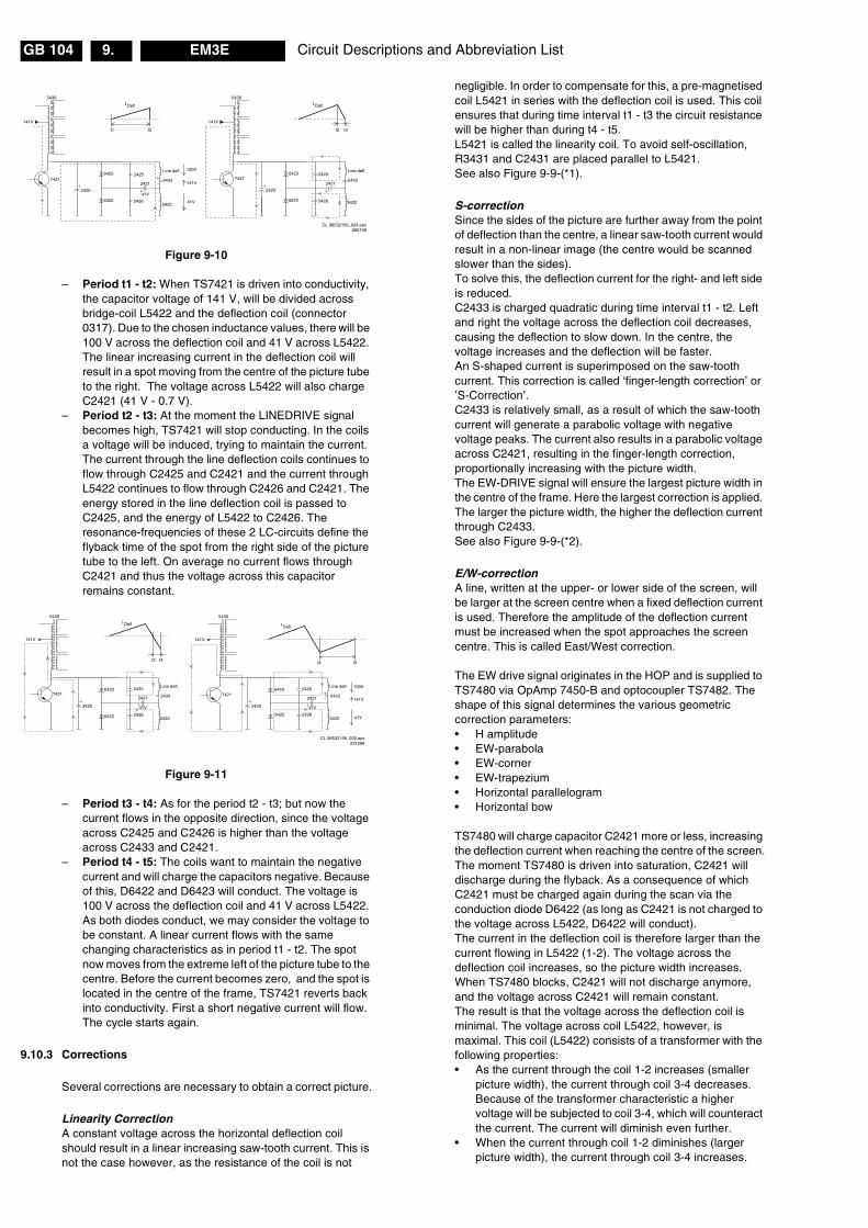
Circuit Descriptions and Abbreviation ListGB 104 EM3E9.
Figure 9-10
– Period t1 - t2: When TS7421 is driven into conductivity,the capacitor voltage of 141 V, will be divided acrossbridge-coil L5422 and the deflection coil (connector0317). Due to the chosen inductance values, there will be100 V across the deflection coil and 41 V across L5422.The linear increasing current in the deflection coil willresult in a spot moving from the centre of the picture tubeto the right. The voltage across L5422 will also chargeC2421 (41 V - 0.7 V).
– Period t2 - t3: At the moment the LINEDRIVE signalbecomes high, TS7421 will stop conducting. In the coilsa voltage will be induced, trying to maintain the current.The current through the line deflection coils continues toflow through C2425 and C2421 and the current throughL5422 continues to flow through C2426 and C2421. Theenergy stored in the line deflection coil is passed toC2425, and the energy of L5422 to C2426. Theresonance-frequencies of these 2 LC-circuits define theflyback time of the spot from the right side of the picturetube to the left. On average no current flows throughC2421 and thus the voltage across this capacitorremains constant.
Figure 9-11
– Period t3 - t4: As for the period t2 - t3; but now thecurrent flows in the opposite direction, since the voltageacross C2425 and C2426 is higher than the voltageacross C2433 and C2421.
– Period t4 - t5: The coils want to maintain the negativecurrent and will charge the capacitors negative. Becauseof this, D6422 and D6423 will conduct. The voltage is100 V across the deflection coil and 41 V across L5422.As both diodes conduct, we may consider the voltage tobe constant. A linear current flows with the samechanging characteristics as in period t1 - t2. The spotnow moves from the extreme left of the picture tube to thecentre. Before the current becomes zero, and the spot islocated in the centre of the frame, TS7421 reverts backinto conductivity. First a short negative current will flow.The cycle starts again.
9.10.3 Corrections
Several corrections are necessary to obtain a correct picture.
Linearity CorrectionA constant voltage across the horizontal deflection coilshould result in a linear increasing saw-tooth current. This isnot the case however, as the resistance of the coil is not
negligible. In order to compensate for this, a pre-magnetisedcoil L5421 in series with the deflection coil is used. This coilensures that during time interval t1 - t3 the circuit resistancewill be higher than during t4 - t5.L5421 is called the linearity coil. To avoid self-oscillation,R3431 and C2431 are placed parallel to L5421.See also Figure 9-9-(*1).
S-correctionSince the sides of the picture are further away from the pointof deflection than the centre, a linear saw-tooth current wouldresult in a non-linear image (the centre would be scannedslower than the sides).To solve this, the deflection current for the right- and left sideis reduced.C2433 is charged quadratic during time interval t1 - t2. Leftand right the voltage across the deflection coil decreases,causing the deflection to slow down. In the centre, thevoltage increases and the deflection will be faster.An S-shaped current is superimposed on the saw-toothcurrent. This correction is called ‘finger-length correction’ or’S-Correction’.C2433 is relatively small, as a result of which the saw-toothcurrent will generate a parabolic voltage with negativevoltage peaks. The current also results in a parabolic voltageacross C2421, resulting in the finger-length correction,proportionally increasing with the picture width.The EW-DRIVE signal will ensure the largest picture width inthe centre of the frame. Here the largest correction is applied.The larger the picture width, the higher the deflection currentthrough C2433.See also Figure 9-9-(*2).
E/W-correctionA line, written at the upper- or lower side of the screen, willbe larger at the screen centre when a fixed deflection currentis used. Therefore the amplitude of the deflection currentmust be increased when the spot approaches the screencentre. This is called East/West correction.
The EW drive signal originates in the HOP and is supplied toTS7480 via OpAmp 7450-B and optocoupler TS7482. Theshape of this signal determines the various geometriccorrection parameters:• H amplitude• EW-parabola• EW-corner• EW-trapezium• Horizontal parallelogram• Horizontal bow
TS7480 will charge capacitor C2421 more or less, increasingthe deflection current when reaching the centre of the screen.The moment TS7480 is driven into saturation, C2421 willdischarge during the flyback. As a consequence of whichC2421 must be charged again during the scan via theconduction diode D6422 (as long as C2421 is not charged tothe voltage across L5422, D6422 will conduct).The current in the deflection coil is therefore larger than thecurrent flowing in L5422 (1-2). The voltage across thedeflection coil increases, so the picture width increases.When TS7480 blocks, C2421 will not discharge anymore,and the voltage across C2421 will remain constant.The result is that the voltage across the deflection coil isminimal. The voltage across coil L5422, however, ismaximal. This coil (L5422) consists of a transformer with thefollowing properties:• As the current through the coil 1-2 increases (smaller
picture width), the current through coil 3-4 decreases.Because of the transformer characteristic a highervoltage will be subjected to coil 3-4, which will counteractthe current. The current will diminish even further.
• When the current through coil 1-2 diminishes (largerpicture width), the current through coil 3-4 increases.
CL 96532156_024.eps060199
141V
7421
Line defl.
2433
5422
6423
6422
2425
2426
2421
Defl
t2 t3
5430
141V
7421
Line defl.
2433
5422
6423
6422
100V
141V
41V
2425
2426
2421
IDefl
t2t1
41V
5430
+-
I
2420 2420
CL 96532156_025.eps231299
141V
Line defl.
2433
5422
2425
2426
I Defl
t3 t4
5430
141V
Line defl.
2433
54226422
2425
2426
I Defl
t5t4
5430
100V
141V
41V
+-
7421 7421
2420
6423
6422
6423
2420
2421
41V
2421
41V

Circuit Descriptions and Abbreviation List GB 105EM3E 9.
Beam-current CorrectionThe ‘EHT-info’ signal at point 10 of the LOT, depends on thevalue of the beam-current and the voltage from dividerR3450, R3451 and C2450. This signal is fed to the HOP totrim the contrast, and to compensate for the changes inpicture-width as a function of the EHT-info, when EHT isdecreased. The ‘EHT-info’ is also used to correct the EW-current.
The ‘DYN-FASE-CORR’ signal, derived from the ‘EHT-info’signal, is fed to the HOP via C2455 and drives a dynamicphase correction necessary because of beam-currentvariations. This is done by regulating TON of the line transistorTS7421.
9.10.4 Secondary Line Voltages
During the blocking time of TS7421, the magnetic energy ofcoil 1 - 5 of the LOT, is transferred to electrical energy in thesecondary winding. Via rectifying and smoothing, the severalsecondary supply voltages are generated, like:• EHT, Focus and Vg2-voltage• +200V for the CRT panel (pin 8 LOT)• +11D for the line deflection (pin 12 LOT)• +13VLOT for the frame deflection (pin 6 LOT)• -15VLOT for the frame deflection (pin 3 LOT)• Filament voltage (pin 9 LOT)
9.11 Vertical (Frame) Deflection (diagram A4)
9.11.1 Frame Stage Drive
Figure 9-12
The HOP drives the frame output stage with a symmetricalsaw-tooth voltage. As the HOP is 'cold' and the frame outputstage is 'hot', they are galvanic isolated. This is done via atransformer (5621). As in the MG-chassis, the HOPgenerates 3 signals needed for the frame output stage:FRAMEDRIVE+, FRAMEDRIVE- and TILT (for rotation).The rotation circuit is kept at the ‘cold’ side of the chassis, toavoid the costs an extra optocoupler.The circuit around IC7440 will amplify this signal and theoutput current will flow through the rotation coil.
9.11.2 Flyback Generator
The frame output stage is supplied via the +13 V and -15 Vcoming from the LOT. The output of the amplifier is 0 VDC, soa coupling capacitor is not required.
During the (forward) scan, a supply of +13 and -15 V issufficient to respond to the slow changing current. Theinternal flyback generator puts a voltage of -15 V on pin 3.Because of the voltage drop over zener diode D6622 (8.2 V),C2622 will be charged to 19 V: being 13 + (15 - 8.2 - 0.7) V.During the flyback scan, the change in current-per-time ismuch larger, so a higher voltage is required. The flybackgenerator will now generate a voltage of +13 V on pin 3.Added to the charge on C2622 this will give a flyback voltageof 32 V (depending on the CRT size, this value can differ).
The amplifier IC (IC7620, pin 5) supplies the saw-toothcurrent to the frame deflection coil. The current through thiscoil is measured via R3620//R3621//R3622 and fed back tothe inverting input of the amplifier.R3624 and C2624 on the output of the amplifier, form a filterfor high frequencies and in that way also preventsoscillations.Peak voltages on the output, e.g. as a result of a possibleflash, are damped by the clamp circuit consisting of D6619,C2627 and R3627. The network consisting of R3625, R3626,R3629 and C2629 form an extra damping circuit.
9.11.3 Protection circuits
Bridge Coil ProtectionThe secondary voltage of the bridge coil L5422, is guarded atthe diode modulator (D6421/6422) via a 10 V zener diode(6499 on diagram A3). When the bridge-coil is workingproperly, the average voltage on D6422 is such that thiszener diode will conduct. It will drive TS7652 into saturation.When, for any reason, the secondary side of the bridge coilis shorted, the average voltage on D6422 will drop below thezener-voltage, and TS7652 will block. Now capacitor C2642is charged. Transistor TS7407 starts conducting and theSUP-ENABLE signal is grounded via R3403. This will switch‘off’ the main supply (see diagram A1).
CL 16532044_021.eps140501
HOTCOLD
3407
3631
3640
FRAMEDEFL.COIL
1620 ROTATION COIL
+8V
7440-A7450-A
7450-B
+8V
+8V
+11V
TDA 7052
TILT 25
2
1
3
FD-
FD+
E/W DRIVE
HOP
FRAME
E/W
HFB-X-RAY-PROT 7455
3642
+13VLOT
-15VLOT
3628
V-SHIFT
V-SHIFT
+8V
5621
76413639
3623
36202653
7482 E/W E/W
2
1 5
4

Circuit Descriptions and Abbreviation ListGB 106 EM3E9.
Frame Output ProtectionVia the circuit built around TS7641 the frame output stage isguarded. If the frame output stage is working properly,TS7641 and TS7652 will both conduct and thereby dischargeC2642. TS7407 is blocked, so the SUP-ENABLE signal is‘high’.If there are frame pulses missing, TS7641 will block andcapacitor C2642 is charged. Transistor TS7407 startsconducting and the SUP-ENABLE signal is grounded viaR3403. This will switch ‘off’ the main supply (see diagramA1).
ARC ProtectionIf there are ‘open’ connections (e.g. bad solder joints) in thehigh energy deflection circuitry, this can lead to damagingeffects (read: fire). For that reason, the E/W current is sensed(via 3479//3480). If this current becomes too high, the‘thyristor’ circuit (TS7653 and TS7654) is triggered. TS7442is switched ‘on’ and TS7443 is forced into conduction. . The‘SUP-ENABLE’ signal is shorted now to ground level, whichwill force the Main Power Supply to Standby mode
9.12 Audio (diagram B6, A6 & A7)
9.12.1 Introduction
All EM3E sets contain one of ITT’s Multi-standard SoundProcessing (MSP) ICs for sound decoding. The diversityarises because each member of the MSP-family handles itsown set of sound standards:• MSP3411: Virtual Dolby decoding.• MSP3412: Dolby ProLogic decoding.Both versions also handle NICAM.
The MSP IC takes care of the main FM sound decoding. AMdecoding for the L system is done by the HIP. Thedemodulated L sound is then again source selected andprocessed in the MSP. The reason for this is the bad AMdetection performance of the MSP. However in case ofNICAM L, it is handled by the MSP.
All MSP versions contain digital audio processing, used forthe basic left/right stereo sound, such as bass, treble,balance, incredible sound and spatial.In addition to that, both versions are capable of Dolbyprocessing:• The MSP3411can perform ‘Virtual Dolby’ processing (a
Dolby approved sound mode for surround soundreproduction with left/right speakers only).
Figure 9-13
• The MSP3412 can perform ‘Dolby ProLogic’ processing(left, right and (mono) surround).
Figure 9-14
Following amplifier configurations are possible:• Virtual Dolby, L/R, 2 x 15 W (88XX-series)• 3D Surround, L/R, Centre, Subwoofer, 4 x 15 W (95XX-
series).
9.12.2 Inputs / Outputs
Both versions can cover 4 stereo inputs and one AM (mono)input. This means in practice: 3 SCART inputs, 1 side inputand 1 AM (mono) input.
Both versions have the following outputs: SCART1 (CVBS/decoder out), SCART2 (record select/WYSIWYR out) andheadphone.
9.12.3 Source Selection
The constant level output to SCART2 is connected via a so-called 'Régimbeau' switch (IC7652) (see also Figure 9-13).This switch is needed to prevent acoustic feedback (Larseneffect). This effect is caused, when EXT2 is chosen as inputsignal, and the output of SCART2 is selected. This meansthat the main picture is also EXT2, which will cause theLarsen effect.To prevent this, the record select must be switched to‘Tuner’. This is especially important when decoders are used,behind a 'transparent' VCR connected to EXT2.
To get a constant level output if the Tuner is selected, theSCART1 output (‘Tuner’ at any time), has to be fed back tothe input selector and selected as input for the MSP(SCART1 input).
The MSP34XX has a separate headphone output, so soundcontrol be done separate from the speakers.
9.12.4 Audio Decoding
At the input a choice can be made between two IF-signals;SIF and SIFM.The selected signal is fed to the AGC. After this, an ADCconverts the IF-signal to digital.Two demodulation channels can process this digital signal.The first one is able to handle FM and NICAM signals. Thesecond one can handle FM and AM signals.Each channel contains a mixer to shift the incoming signal inthe frequency domain. This shift is determined by the valueof a DCO.After the down-mix, the signal is fed, via a filter, to adiscriminator. From here the AM, FM or NICAMdemodulation can be performed.
MONO-IN
76517770 HEADPHONE
CINCH
L/RMAIN
SCART 2
SCART 1 / decoder out
Constant Level
ANA_INI+
DACA_L/R
DACM_L/R
SC2-OUT
SC1-OUT
SC1-IN
MICRONASMSP3411SC2-IN
SC3-IN
TUNER L/R
28/29
CL L/R
20/21
17/18
25/26
SC4-IN
EXT1 L/R
EXT2 L/R
FRONT L/R
EXT3 L/R
44/45
50
47
41/42
38/39
35/36
CL 16532044_028.eps140501
MAIN IFHIP
7700
765274HC4053
1/3
2/54/15
SEL_IN_2
16
MONO-IN
7651
CENTER
SCART 2
SCART 1 / decoder out
Constant LevelVariable Level
ANA_IN1+
DACA_L/R
DACM_L/R
D_CTR_I/O_0
SC1-OUT
SC1-IN
MICRONASMSP3412G
SC2-IN
SC3-IN
TUNER L/R
28/29
CL L/R
25/26
7653
17/18
24
DACM_L/R
DACM_SUB
DACM_C
SC2-OUT
23
22
"Set is center"
20/21
SC4-IN
EXT1 L/R
EXT2 L/R
FRONT L/R
EXT3 L/R
44/45
50
47
41/42
38/39
35/36
CL 16532044_029.eps140501
MAIN IFHIP
7702
74HC4053
2 times74HC4053
SEL_IN_27652
Surround cinchor Phone plug
MAIN
7700
SUBWOOFER
7702
HEADPHONE
7770
765274HC4053

Circuit Descriptions and Abbreviation List GB 107EM3E 9.
Both channels contain an 'automatic carrier mute' function,which automatically mutes the output of the analogue sectionwhen no carrier is detected.After demodulation, the FM-signals are subjected to a de-emphasis operation. After that the matrix of the stereosystem is applied.
9.12.5 Audio Processing
The sound processing in EM3E is completely done by theMSP's:• Volume control is done by the user via the SOUND
menu.• Tone control in 'Stereo' sets is done via the BASS/
TREBLE control, in 'Virtual Dolby' sets via the 5-bandequaliser.
• Headphone control, the MSP has a separate Headphoneoutput so separate sound control is possible.
Automatic Volume Levelling (AVL)One of the features of the MSP-family is Automatic VolumeLimiting (AVL). If used, it limits the big volume differences inthe broadcast between e.g. news transmissions andcommercials, or within a movie.To be able to get a Dolby approval (for the Virtual Dolby sets),the AVL feature must be switchable. Therefore, the AVLfeature is customer switchable via the menu.
9.12.6 Audio Amplifier (diagram A6)
The audio amplifier is an integrated ‘class-D’ power amplifierIC, the TDA7490. It delivers an output of 2 x 15 WRMS to 2full range speakers. For the higher specified sets, asubwoofer and centre speaker are easy to implement, byadding a second amplifier.
PrincipleAudio-power-amplifier systems have traditionally used linearamplifiers, which are well known for being inefficient. In fact,a linear Class AB amplifier is designed to act as a variableresistor network between the power supply and the load. Thetransistors operate in their linear region and the voltage thatis dropped across the transistors (in their role as variableresistors) is lost as heat, particularly in the output transistors.Class D amplifiers were developed as a way to increase theefficiency of audio-power-amplifier systems.
The Class D amplifier works by varying the duty cycle of aPulse Width Modulated (PWM) signal.By comparing the input voltage to a triangle wave, theamplifier increases duty cycle to increase output voltage, anddecreases duty cycle to decrease output voltage.The output transistors of a Class D amplifier switch from full‘off’ to full ‘on’ (saturated) and then back again, spending verylittle time in the linear region in between. Therefore, very littlepower is lost to heat.If the transistors have a low ‘on’ resistance RDS(ON), littlevoltage is dropped across them, further reducing losses.
The advantage of Class D is increased efficiency (= less heatdissipation). Class D amplifiers can drive the same outputpower as a Class AB amplifier using less supply current.The disadvantage is the large output filter that drives up costand size. The main reason for this filter, is that the switchingwaveform results in maximum current flow. This causes moreloss in the load, which causes lower efficiency.An LC filter with a cutoff frequency less than the Class Dswitching frequency (200 kHz), allows the switching currentto flow through the filter instead of the load. The filter is lesslossy than the speaker, which causes less power dissipatedat high output power and increases efficiency in most cases.
The supply voltage is a symmetrical voltage of +/- 16 V (or +/- 19 V depending on the set execution), generated by themain supply via L5512 (or L5506).
MuteSound-mute is done via the STBY-MUTE line connected topin 6 (tri-state input) of the amplifier IC. This line is activatedvia the SOUND-ENABLE line (software controlled) and/orPOR line (hardware controlled).This signal is inverted by TS7701 and/or TS7703, as a resultof which at a high level of the SOUND-ENABLE signal,current is sinked from pin 2 and the IC mutes.
ProtectionA loudspeaker DC protection is implemented. The amplifierIC TDA7490 has a ‘standby-mute-play’ feature via the tri-state input pin 6. When the voltage on pin 6 is:• 0 - 0.7 V, the IC is in ‘standby’ mode• 1.7 - 2.5 V, the IC is in ‘mute’ mode• 4 - 5 V, the IC is in ‘play’ mode (normal operation).Note: this is a ‘local’ protection, not known to themicroprocessor.
This works as follows:• During normal operation, VX is ‘low’ (0 V) and VY is ‘high’
(+5 V).• When a positive DC-voltage is detected on a
loudspeaker output (= VX ), TS7704, TS7706 andTS7707 will conduct, making VY ‘low’.
• When a negative DC-voltage is detected on aloudspeaker output (= VX ), TS7705, TS7706 andTS7707 will conduct, making VY also ‘low’.
When VY is ‘low’ (read 0 V), the tri-state input (pin 6) puts theamplifier IC in ‘standby’ mode.
Figure 9-15
9.12.7 Headphone Amplifier (diagram A7)
The headphone amplifier is a straight forward OpAmpamplifier (7770, NJM4556). It is supplied with +/- 16 V.
9.13 Teletext and NexTView
9.13.1 Teletext
The TXT-decoder in the OTC gets its video signal directly onpin 5 (from the HIP).The RGB-outputs are available on pins 77/78/79. Fastblanking is realised via pen 80.The DRAM (IC7007) of the microprocessor is used forstorage of the TXT pages.
CL 16532044_017.eps140501
OUT
R
L
(RES)
C/SW
(PROT 1)
2778
7704
47K
47K
10K
+5V
47K
33K
7705
2705
7707
470N
VYOUT
6 23
VX
7703
7706
7701
10K
10K
Sound Enable
POR
SOUND-IC's
7700/7702
STANDBY-MUTE(TRISTATE)
100K
10K

Circuit Descriptions and Abbreviation ListGB 108 EM3E9.
9.13.2 NexTView
NexTView allows the user to display a program guide on theTV screen, that contains extensive information for eachprogram (only when supported by the programs provider).
This information can be displayed in a number of differentsummaries:• DAY: The daily summary shows, from the current
moment, the program schedule for several stations for ashort time ahead.
• CHANNEL: The channel summary shows the programschedule for one station.
• THEME: The theme summary shows, for each theme,the program schedule of the various stations. Thesethemes consist of sport, film, culture, etc. and isdetermined from the station side.
NexTView does not have to restrict itself to information aboutthe station that is being viewed, but also offers informationabout other stations. In the various summaries 3 differentcommands can be given for the various program overviews.These commands appear as follows:• WATCH: The set immediately switches over to the
station concerned.• REMINDER: The start time and date and the station of
the program concerned is stored in the TV reminder list.The TV will give an OSD-message with the programinformation, or switch on the set at the correct moment(provided the set is in Standby) and tune to the stationconcerned.
• RECORD: The timer of the video recorder with ‘EasylinkPlus’ is programmed with the data of the programconcerned. There has to be a video recorder (withEasylink Plus) connected to SCART2 otherwise the‘RECORD’ function will not be highlighted. Theconnection is via pin 10 from SCART. This means that ithas to be a full SCART or at least pin 10 has to be wired.
In order to be able to realise NexTView, two teletext type dataflows, Data stream 1 and 2, are transmitted with various sub-code pages of information. This data flow can transportlimited information (max. 40 pages). Data stream 1 is quickrepeating with a repetition time of approximately 20 to 30seconds. However, Data stream 2 has a much longerrepetition time of approximately half an hour and has a largetransport capacity.• Data stream 1 contains information of the station that is
being viewed.• Data stream 2 contains up to one week of advance
information from various stations that are covered by theprovider.
9.14 CRT / SCAVEM / Rotation (diagram F)
9.14.1 RGB Amplifiers
On the CRT panel, the RGB amplifier (TDA6108, IC7307) islocated. Via the outputs 7, 8 and 9 the cathodes of the picturetube are driven.The supply voltage for the amplifier is 200 V and is derivedfrom the LOT.
9.14.2 SCAVEM
The SCAn VElocity Modulation (SCAVEM) circuitry isimplemented in the layout of the picture tube panel. It is thusnot an extra module. This circuit influences the horizontaldeflection as a function of the picture content. In an idealsquare wave, the sides are limited in slope due to a limitedbandwidth (5 MHz).
PrincipleSCAVEM will improve the slope as follows:At a positive slope, a SCAVEM current is generated whichsupports the deflection current. At the first half of the slope,the spot is accelerated and the picture is darker. At thesecond half of the slope, the spot is delayed and the slopebecomes steeper.At the end of the slope, the SCAVEM-current decays to zeroand the spot is at the original position. An overshoot occurswhich improves the impression of sharpness.At the negative slope, the SCAVEM-current counteracts thedeflection. During the first half of the slope, the spot isdelayed, the slope becomes steeper. During the second halfthe spot accelerates, the SCAVEM-current is zero at the endof the slope.
ImplementationVia the three resistors R33358, R33359 and R3360, Red,Green and Blue are added together, buffered and offered tothe emitter of TS7300. On the collector of this transistor,configured in a common base, the sum of these 3 signals isobtained. Via the emitter follower formed with TS7301, thissignal is conveyed to the differentiator C2330, R3324 andR3318. Only the high frequencies are differentiated (smallRC-time).The positive and negative pulses of this signal driverespectively TS7303 and TS7302 into conductivity. The DCsetting of the output stage is set by R3304, R3308, R3316and R3319. The working voltage of the transistors is settledat half the supply voltage.At the positive section of the pulse, the current flows throughR3318, C2307, the SCAVEM-coil and TS7303. At thenegative section of the pulse, the current flows throughR3318, C2309, the SCAVEM-coil and TS7302.
9.14.3 Rotation
In sets with a rotation coil (wide screen sets), the amount offrame rotation is adjusted with the DAC-output of the HOP(see also 'Vertical Deflection').
9.15 Software Related Features
Following features are described:• Auto TV• ‘Switch On’ Behaviour
9.15.1 AutoTV
The AutoTV (or 'Automatic Picture Control' or 'ActiveControl') aims at giving the customer the best possiblepicture performance at any time. Therefor it does real timeprocessing of the video signal and as a result, it decides toadapt several video parameters throughout the wholechassis.
The AutoTV feature integrates traditional pictureperformance, AutoTV functionality and 'smart controls' inorder to come to a kind of 'super smart' TV. It can besubdivided in:• Auto Noise Reduction. This algorithm measures the
amount of noise in the incoming video signal (this is doneby the LIMERIC part of the PICNIC). As a result of thismeasurement, the amount of noise in the picture iscorrected, starting from that noise level which isannoying for the customer. Which parameters exactlycan be used is depending on the hardware.
• Auto Sharpness. This algorithm measures the amountof sharpness via the bandwidth of the incoming videosignal and adapts the peaking frequency in the PICNICaccording to this info. If the 'sharpness meter' sees thevideo content as 'sharp', high frequency peaking will beused. On the other hand, if the picture content is seen as
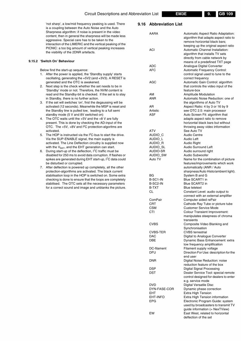
Circuit Descriptions and Abbreviation List GB 109EM3E 9.
'not sharp', a low/mid frequency peaking is used. Thereis a coupling between the Auto Noise and the AutoSharpness algorithm: if noise is present in the videocontent, then in general the sharpness will be made lessaggressive. Special care has to be taken to theinteraction of the LIMERIC and the vertical peaking of thePICNIC: a too big amount of vertical peaking increasesthe visibility of the 2DNR artefacts.
9.15.2 ‘Switch On’ Behaviour
Below find the start-up sequence:1. After the power is applied, the 'Standby supply' starts
oscillating, generating the +5V2 (and +3V3). A RESET isgenerated and the OTC is awakened.
2. Next step is the check whether the set needs to be in‘Standby’ mode or not. Therefore, the NVM content isread and the Standby-bit is checked. If the set is to stayin Standby, there is no further action.
3. If the set will switches 'on', first the degaussing will beactivated (12 seconds). Meanwhile the MSP is reset andthe Standby line is pulled low, leading to a full semistandby mode (5 V and 8V switched on)
4. The OTC waits until the +5V and the +8 V are fullypresent. This is done by checking the AD-input of theOTC. The +5V, +8V and I2C protection-algoritms areactivated.
5. The HOP is instructed via the I2C-bus to start the drive.Via the SUP-ENABLE signal, the main supply isactivated. The Line Deflection circuitry is supplied nowwith the VBAT, and the EHT generation can start.
6. During start-up of the deflection, I�C traffic must bedisabled for 250 ms to avoid data corruption. If flashes orspikes are generated during EHT start-up, I�C data couldbe disturbed or corrupted.
7. After deflection is powered up completely, all the otherprotection-algorithms are activated. The black currentstabilisation loop in the HOP is switched on. Some extrachecking is done to ensure that the loops are completelystabilised. The OTC sets all the necessary parametersfor a correct sound and image and unblanks the picture.
9.16 Abbreviation List
AARA Automatic Aspect Ratio Adaptation:algorithm that adapts aspect ratio toremove horizontal black bars;keeping up the original aspect ratio
ACI Automatic Channel Installation:algorithm that installs TV setsdirectly from cable network bymeans of a predefined TXT page
ADC Analogue Digital ConverterAFC Automatic Frequency Control:
control signal used to tune to thecorrect frequency
AGC Automatic Gain Control: algorithmthat controls the video input of thefeature-box
AM Amplitude ModulationANR Automatic Noise Reduction: one of
the algorithms of Auto TVAR Aspect Ratio: 4 by 3 or 16 by 9Artistic see OTC 2.5: main processorASF Auto Screen Fit: algorithm that
adapts aspect ratio to removehorizontal black bars but withoutthrowing away video information
ATV See Auto TVAUDIO_C Audio CentreAUDIO_L Audio LeftAUDIO_R Audio RightAUDIO_SL Audio Surround LeftAUDIO-SR Audio surround rightAUDIO_SW Audio SubwooferAuto TV Name for the combination of picture
features/improvements which workautomatically (ANR / Autosharpness/Auto Histo/ambient light).
BG System B and GB-SC1-IN Blue SCART1 inB-SC2-IN Blue SCART2 inB-TXT Blue teletextCL Constant Level: audio output to
connect with an external amplifierComPair Computer aided rePairCRT Cathode Ray Tube or picture tubeCSM Customer Service ModeCTI Colour Transient Improvement:
manipulates steepness of chromatransients
CVBS Composite Video Blanking andSynchronisation
CVBS-TER CVBS terrestrialDAC Digital to Analogue ConverterDBE Dynamic Bass Enhancement: extra
low frequency amplificationDC-filament Filament supply voltageDFU Direction For Use: description for the
end userDNR Digital Noise Reduction: noise
reduction feature of the boxDSP Digital Signal ProcessingDST Dealer Service Tool: special remote
control designed for dealers to entere.g. service mode
DVD Digital Versatile DiscDYN-FASE-COR Dynamic phase correctionEHT Extra High TensionEHT-INFO Extra High Tension informationEPG Electronic Program Guide: system
used by broadcasters to transmit TVguide information (= NexTView)
EW East West, related to horizontaldeflection of the set
Circuit Descriptions and Abbreviation ListGB 110 EM3E9.
EXT External (source), entering the setvia SCART or via cinches
FBL Fast Blanking: DC signalaccompanying RGB signals
FBX Feature Box: part of small signal /separate module which contains 100Hz processing, extra featuring andAutoTV algorithms
FILAMENT Filament of CRTFLASH Flash memoryFM Field Memory or Frequency
ModulationG-TXT Green teletextHA50 Horizontal Acquisition 1fh:
horizontal sync pulse coming out ofthe HIP
HD100 Horizontal Drive 2fh: horizontal syncpulse coming out of the feature-box
HFB Horizontal Flyback Pulse: horizontalsync pulse from large signaldeflection
HIP High-end video Input Processor:video and chroma decoder of EM3E
HOP High-end video Output Processor:video, sync and geometry controllerof EM3E
HP HeadphoneInterlaced Scan mode where two fields are
used to form one frame. Each fieldcontains half the number of the totalamount of lines. The fields arewritten in ‘pairs’, causing line flicker.
Last Status The settings last chosen by thecustomer and read and stored inRAM or in the NVM. They are calledat start-up of the set to configure itaccording the customers wishes
LDP Line Deflection ProtectionLED Light Emitting DiodeLINE-DRIVE Line drive signalLNA Low Noise AdapterLSP Large signal panelMSP Multi-standard Sound Processor:
ITT sound decoder of EM3EMUTE Mute-LineNC Not ConnectedNVM Non Volatile Memory: IC containing
TV related data e.g. alignmentsO/C Open CircuitON/OFF LED On/Off control signal for the LEDOSD On Screen DisplayOTC On screen display Teletext and
Control; also named Artistic(SAA5800)
P50 Project 50 communication: protocolbetween TV and peripherals
PCB Printed Circuit boardPICNIC Peripheral Integrated Combined
Network IC: main IC for 100 Hzfeaturing and feature processing
Progressive Scan Scan mode where all scan lines aredisplayed in one frame at the sametime, creating a double verticalresolution.
PTP Picture Tube PanelRAM Random Access MemoryR-TXT Red teletextRC Remote ControlRC5 / RC6 Signal protocol from the remote
control receiverRESET Reset signalROM Read Only MemorySAM Service Alignment ModeSC Sandcastle: pulse derived from sync
signals
SCAVEM Scan Velocity ModulationS/C Short CircuitSIF Sound Intermediate FrequencySIMM 80-fold connector between LSP and
SSBSNERT Synchronous No parity Eight bit
Reception and TransmitSSB Small Signal BoardSTBY StandbySW SubwooferTXT TeletextTXT DS Teletext Dual Screen�P MicroprocessorU100 U from Feature BoxV100 V from Feature BoxVA50 Vertical Acquisition 1FhVBAT Main supply for deflection (mostly
141 V)VD100 Vertical Drive 2fh: vertical sync
pulse from deflectionVFB Vertical Flyback Pulse: vertical sync
pulse coming from the feature boxVL Variable Level out: processed audio
output towards external amplifierWYSIWYR What You See Is What You Record:
record selection that follows mainpicture and sound
XTAL Quartz crystalY100 Y from Feature BoxY-OUT Luminance-signal to HOP IC

Spare Parts List GB 111EM3E 10.
10. Spare Parts List
Large Signal Panel [A]
Various
0010 2422 025 16374 2P Male0020 4822 267 10774 2P Male0032 4822 492 70788 IC-SPRING0037 3104 304 21112 LOT SSB SUPPORT0045 4822 267 10734 5P MALE0065 3104 304 22031 LOT SPACER0066 3104 304 21591 SCART SUPPORT
BRACKET0150 4822 265 11253 FUSE HOLDER0153 4822 265 11253 FUSE HOLDER0317 4822 265 20723 2P MALE0324 3104 311 01881 CABLE 7P 480mm0325 2422 025 16382 3P Male0735 2422 025 16407 3P Male0736 2422 025 16382 3P Male0936 2422 025 12485 11P Male0940 4822 267 10968 11P FEMALE0943 4822 267 10748 3P MALE0945 4822 267 10735 3P MALE0946 5322 268 90415 2P MALE0947 4822 267 10734 5P MALE1001 4822 252 60151 SURGE PROTECT1002 2422 132 07411 RELAY 1P 5V 5A1003 4822 267 10973 1P1200 4822 210 10848 UV1316/A I U-21205 2422 025 16599 80P Female SIMM1501 4822 070 34002 FUSE 4A1503 2422 086 10912 FUSE 2,5A1901 4822 267 10771 IC SOCKET 42P1902 4822 267 10982 2P8000 4822 320 12525 CABLE8001 4822 320 20234 EHT CABLE8015 4822 320 20216 CABLE
3122 785 100 Supply Kit Mains SupplyEM2E
3122 785 100 Supply Kit Standby SupplyEM2E
3122 785 100 Line Repair Kit EM2E
�
2101 5322 122 32818 2.2nF 10% 100V2102 4822 124 40248 10�F 20% 63V2103 5322 122 32531 100pF 5% 50V2104 4822 123 14025 2200�F 20% 16V2105 5322 122 32531 100pF 5% 50V2106 5322 126 10223 4.7nF 10% 63V2107 5322 122 32818 2.2nF 10% 100V2108 4822 121 70162 10nF 5% 400V2109 4822 126 13482 470nF 80/20% 16V2110 5322 121 42498 680nF 5% 63V2111 4822 121 43526 47nF 5% 250V2113 4822 122 33127 2.2nF 10% 63V2114 4822 126 10206 2.2nF 10% 500V2200 4822 124 40196 220�F 20% 16V2201 4822 126 14076 220nF 25V2202 4822 126 13473 220nF 80-20% 50V2203 4822 124 41584 100�F 20% 10V2400 4822 124 11575 47�F 20% 160V2412 4822 126 13751 47nF 10% 63V2413 4822 124 12255 10�F 20% 50V2414 4822 126 13751 47nF 10% 63V2415 4822 122 33575 220pF 5% 63V2417 4822 126 14076 220nF 25V2419 4822 126 14237 470pF 10% 2KV2420 4822 121 70594 1nF 5% 2KV2421 2022 333 00086 470nF 5% 250V2421 4822 121 42634 560nF 5% 250V2425 4822 121 10526 9N1 5% 2KV2425 4822 121 70435 10nF 5% 2KV2426 4822 121 10653 22nF 5% 630V2426 4822 121 10658 24nF 5% 630V2429 4822 121 43343 4.7nF 10% 400V2430 4822 121 41857 10nF 5% 250V2431 4822 121 42077 6.8nF 10% 400V2431 4822 126 13599 3.3nF 10% 500V2433 2022 333 00086 470nF 5% 250V2433 4822 121 42634 560nF 5% 250V2435 4822 121 10526 9N1 5% 2KV2450 5322 121 42578 100nF 5% 250V2455 5322 126 10511 1nF 5% 50V2460 4822 124 40784 3300�F 20% 16V2461 4822 122 31177 470pF 10% 500V2462 4822 124 80061 1000�F 20% 25V
2463 4822 122 31177 470pF 10% 500V2464 4822 124 80061 1000�F 20% 25V2465 4822 122 31177 470pF 10% 500V2468 4822 124 12297 4.7�F 20% 350V2469 4822 122 31177 470pF 10% 500V2480 4822 121 51442 2.2nF 10% 50V2489 4822 124 40433 47�F 20% 25V2490 4822 122 33891 3.3nF 10% 63V2491 4822 124 40768 0.47�F 20% 100V2492 4822 126 14076 220nF 25V2495 4822 126 13838 100nF 20% 50V2499 4822 126 13838 100nF 20% 50V2501 4822 126 11524 1.5nF 10% 1KV2502 5322 122 32818 2.2nF 10% 100V2503 5322 121 42489 33nF 5% 250V2505 4822 126 14504 3.3nF 20% 250V2507 4822 126 13589 470nF 275V2508 4822 126 14153 2.2nF 10%B 1KV2509 4822 126 14153 2.2nF 10%B 1KV2510 4822 124 12415 220�F 20% 400V2512 4822 124 12056 1000�F 20% 35V2513 5322 122 34099 470pF 10% 63V2514 5322 122 31863 63V 330pF 5%2515 4822 124 11575 47�F 20% 160V2518 4822 126 11308 47pF 5% 500V2519 5322 122 32818 2.2nF 10% 100V2520 4822 126 14585 100nF 10% 50V2521 4822 122 33216 270pF 5% 50V2528 4822 126 14585 100nF 10% 50V2530 4822 126 14585 100nF 10% 50V2531 4822 122 31169 1.5nF 10% 500V2535 4822 121 43913 470nF 10% 100V2536 4822 126 10206 2.2nF 10% 500V2537 4822 124 11913 22nF 20% 275V2538 5322 126 10223 4.7nF 10% 63V2600 4822 121 43913 470nF 10% 100V2601 4822 121 51252 470nF 5% 63V2602 4822 124 40433 47�F 20% 25V2603 4822 122 33177 10nF 20% 50V2604 4822 124 40248 10�F 20% 63V2610 4822 122 33127 2.2nF 10% 63V2620 4822 126 14076 220nF 25V2621 4822 126 13838 100nF 20% 50V2622 4822 124 40255 100�F 20% 63V2624 4822 121 51252 470nF 5% 63V2625 4822 121 51252 470nF 5% 63V2627 5322 124 40641 10�F 20% 100V2642 4822 124 40255 100�F 20% 63V2700 4822 124 21913 1�F 20% 63V2701 4822 124 21913 1�F 20% 63V2730 4822 124 81151 22�F 50V2731 4822 124 81151 22�F 50V2732 4822 124 40255 100�F 20% 63V2733 4822 124 40255 100�F 20% 63V2734 4822 124 81151 22�F 50V2735 4822 124 81151 22�F 50V2736 5322 122 31865 1.5nF 10% 63V2737 5322 122 31865 1.5nF 10% 63V2756 4822 126 13751 47nF 10% 63V2760 4822 124 80061 1000�F 20% 25V2761 4822 124 80061 1000�F 20% 25V2765 4822 124 40255 100�F 20% 63V2767 4822 124 40255 100�F 20% 63V2782 4822 126 13751 47nF 10% 63V2902 5322 122 31863 330pF 5% 63V2903 5322 122 31863 330pF 5% 63V2906 5322 122 32531 100pF 5% 50V2909 5322 122 31863 330pF 5% 63V2910 5322 122 32531 100pF 5% 50V2912 4822 124 40248 10�F 20% 63V2913 4822 126 14585 100nF 10% 50V2915 5322 122 31863 330pF 5% 63V2916 5322 122 31863 330pF 5% 63V2917 5322 122 32531 100pF 5% 50V2919 5322 122 31863 330pF 5% 63V2920 5322 122 32531 100pF 5% 50V2923 5322 122 31863 330pF 5% 63V2925 5322 122 31863 330pF 5% 63V2926 4822 124 81044 470�F 20% 6.3V2927 4822 124 40433 47�F 20% 25V2941 5322 122 31865 1.5nF 10% 63V2942 5322 122 31865 1.5nF 10% 63V2951 4822 124 21913 1�F 20% 63V2952 4822 126 13751 47nF 10% 63V2953 4822 126 13751 47nF 10% 63V
�
3101 4822 053 20106 10M 5% 0.25W
3102 4822 050 26801 680� 1% 0.6W3103 4822 050 26801 680� 1% 0.6W3104 4822 116 52195 47� 5% 0.5W3105 4822 050 26801 680� 1% 0.6W3106 4822 116 52256 2k2 5% 0.5W3107 4822 116 52256 2k2 5% 0.5W3108 4822 116 52182 15� 5% 0.5W3110 4822 052 10109 10� 5% 0.33W3113 4822 116 52182 15� 5% 0.5W3114 4822 116 83872 220� 5% 0.5W3117 4822 116 52195 47� 5% 0.5W3118 4822 050 24708 4�7 1% 0.6W3120 4822 051 20109 10� 5% 0.1W3123 4822 116 52176 10� 5% 0.5W3124 4822 116 52199 68� 5% 0.5W3125 4822 116 52182 15� 5% 0.5W3126 4822 050 21003 10k 1% 0.6W3127 4822 116 52289 5k6 5% 0.5W3200 4822 051 20101 100� 5% 0.1W3201 4822 051 20101 100� 5% 0.1W3250 4822 051 20223 22k 5% 0.1W3402 4822 117 10837 100k 1% 0.1W3403 4822 051 20101 100� 5% 0.1W3404 4822 051 20471 470� 5% 0.1W3406 4822 051 20101 100� 5% 0.1W3407 4822 117 10833 10k 1% 0.1W3410 4822 051 20479 47� 5% 0.1W3411 4822 116 52193 39� 5% 0.5W3414 4822 117 13577 330� 1% 1.25W3415 3198 012 31590 15� 5% 3W3415 4822 117 12836 12� 5% 3W3417 4822 116 52176 10� 5% 0.5W3418 4822 050 22704 270k 1% 0.6W3431 4822 052 10101 100� 5% 0.33W3431 4822 052 10221 220� 5% 0.33W3450 4822 116 52303 8k2 5% 0.5W3450 4822 116 83961 6k8 5%3451 4822 116 52257 22k 5% 0.5W3460 4822 052 10108 1� 5% 0.33W3461 4822 052 10108 1� 5% 0.33W3462 4822 052 10108 1� 5% 0.33W3463 4822 052 10108 1� 5% 0.33W3464 4822 052 10108 1� 5% 0.33W3465 4822 052 10108 1� 5% 0.33W3466 4822 052 10688 6�8 5% 0.33W3466 4822 052 10828 8�2 5% 0.33W3467 4822 052 10108 1� 5% 0.33W3468 4822 052 11688 6�8 5% 0.5W3475 4822 116 52175 100� 5% 0.5W3481 4822 116 52175 100� 5% 0.5W3483 4822 051 10102 1k 2% 0.25W3484 4822 117 11139 1k5 1% 0.1W3485 4822 117 11454 820� 1% 0.1W3486 4822 117 12955 2k7 1% 0.1W3487 4822 117 11449 2k2 1% 0.1W3488 4822 116 52272 330k 5% 0.5W3488 4822 116 83874 220k 5% 0.5W3489 4822 117 11449 2k2 1% 0.1W3491 4822 050 21504 150k 1% 0.6W3495 4822 051 20683 68k 5% 0.1W3496 4822 117 11507 6k8 1% 0.1W3497 4822 117 10834 47k 1% 0.1W3498 4822 051 20472 4k7 5% 0.1W3499 4822 117 10837 100k 1% 0.1W3500 4822 117 12074 1�5 10% 7W3501 3198 013 04710 470� 2% 1/2W3504 4822 116 83883 470� 5% 0.5W3507 4822 050 21604 160k 1% 0.6W3508 3198 012 16820 6.8k 1W3509 2322 595 90021 VDR DC 1M A/495V3510 4822 117 11951 2k 1% 0.1W3511 4822 116 52276 3k9 5% 0.5W3512 4822 116 52297 68k 5% 0.5W3513 4822 116 52272 330k 5% 0.5W3514 4822 053 10108 1� 5% 1W3515 4822 053 10108 1� 5% 1W3516 4822 116 10075 9� 220V3518 4822 050 11204 120k 1% 0.4W3519 4822 051 20223 22k 5% 0.1W3520 4822 053 11333 33k 5% 2W3521 4822 117 10118 1M 5% 0.5W3522 4822 116 83961 6k8 5%3523 4822 051 20105 1M 5% 0.1W3524 4822 051 10102 1k 2% 0.25W3525 4822 051 20479 47� 5% 0.1W3526 4822 116 83303 1� 2W3527 4822 117 11454 820� 1% 0.1W3528 4822 117 10833 10k 1% 0.1W3529 4822 051 20472 4k7 5% 0.1W

Spare Parts ListGB 112 EM3E10.
3530 4822 116 52297 68k 5% 0.5W3531 4822 117 10833 10k 1% 0.1W3533 4822 051 20159 15� 5% 0.1W3535 4822 051 20273 27k 5% 0.1W3536 4822 117 10837 100k 1% 0.1W3537 4822 117 10833 10k 1% 0.1W3538 4822 051 20332 3k3 5% 0.1W3539 4822 117 10833 10k 1% 0.1W3540 4822 117 10834 47k 1% 0.1W3541 4822 117 10833 10k 1% 0.1W3542 3198 012 11570 0�15 5% 1W3543 4822 051 20478 4�7 5% 0.1W3544 4822 051 20479 47� 5% 0.1W3600 4822 050 22205 2M2 1% 0.6W3601 4822 050 22205 2M2 1% 0.6W3602 4822 051 20332 3k3 5% 0.1W3603 4822 101 11319 100� LIN3605 4822 051 20273 27k 5% 0.1W3606 4822 051 10102 1k 2% 0.25W3607 4822 051 20223 22k 5% 0.1W3608 4822 051 20223 22k 5% 0.1W3609 4822 101 11193 47k 30% LIN 0.1W3610 4822 051 20683 68k 5% 0.1W3611 4822 051 20822 8k2 5% 0.1W3612 4822 051 20274 270k 5% 0.1W3613 4822 051 20274 270k 5% 0.1W3614 4822 050 21005 1M 1% 0.6W3615 4822 050 18204 820k 1% 0.4W3615 4822 116 52292 560k 5% 0.5W3616 4822 116 52285 470k 5% 0.5W3617 4822 050 11002 1k 1% 0.4W3618 4822 051 10102 1k 2% 0.25W3619 4822 051 20562 5k6 5% 0.1W3620 4822 116 80176 1� 5% 0.5W3620 4822 116 80676 1�5 5% 0.5W3621 4822 116 80176 1� 5% 0.5W3622 4822 116 80176 1� 5% 0.5W3623 4822 117 10834 47k 1% 0.1W3624 4822 052 10158 1�5 5% 0.33W3625 4822 116 83872 220� 5% 0.5W3626 4822 116 83872 220� 5% 0.5W3627 4822 050 21003 10k 1% 0.6W3630 4822 051 10102 1k 2% 0.25W3631 4822 051 20332 3k3 5% 0.1W3632 4822 117 10833 10k 1% 0.1W3633 4822 050 21003 10k 1% 0.6W3644 4822 117 10833 10k 1% 0.1W3645 4822 116 52245 150k 5% 0.5W3652 4822 051 20101 100� 5% 0.1W3701 4822 117 10833 10k 1% 0.1W3702 4822 117 10833 10k 1% 0.1W3730 4822 117 10833 10k 1% 0.1W3731 4822 117 10833 10k 1% 0.1W3732 4822 051 20822 8k2 5% 0.1W3733 4822 051 20822 8k2 5% 0.1W3734 4822 117 10834 47k 1% 0.1W3735 4822 117 10834 47k 1% 0.1W3736 4822 051 10102 1k 2% 0.25W3737 4822 051 10102 1k 2% 0.25W3738 4822 117 11148 56k 1% 0.1W3739 4822 117 11148 56k 1% 0.1W3740 4822 051 20683 68k 5% 0.1W3741 4822 051 20683 68k 5% 0.1W3742 4822 116 52199 68� 5% 0.5W3743 4822 116 52199 68� 5% 0.5W3756 4822 117 10833 10k 1% 0.1W3762 4822 051 20828 8�2 5% 0.1W3765 4822 117 11507 6k8 1% 0.1W3770 4822 117 10834 47k 1% 0.1W3771 4822 116 83933 15k 1% 0.1W3773 4822 116 83933 15k 1% 0.1W3789 4822 051 20828 8�2 5% 0.1W3790 4822 051 10102 1k 2% 0.25W3792 4822 051 10102 1k 2% 0.25W3900 4822 116 83868 150� 5% 0.5W3901 4822 117 10353 150� 1% 0.1W3902 4822 117 10353 150� 1% 0.1W3903 4822 117 10353 150� 1% 0.1W3905 4822 116 83883 470� 5% 0.5W3906 4822 116 52201 75� 5% 0.5W3907 4822 051 20561 560� 5% 0.1W3908 4822 116 52201 75� 5% 0.5W3909 4822 116 52201 75� 5% 0.5W3910 4822 116 52201 75� 5% 0.5W3911 4822 116 52201 75� 5% 0.5W3913 4822 116 52201 75� 5% 0.5W3915 4822 116 52201 75� 5% 0.5W3916 4822 051 20822 8k2 5% 0.1W3918 4822 051 20392 3k9 5% 0.1W3919 4822 051 10102 1k 2% 0.25W3920 4822 051 10102 1k 2% 0.25W3921 4822 117 10353 150� 1% 0.1W3922 4822 117 10353 150� 1% 0.1W3923 4822 117 10353 150� 1% 0.1W
3924 4822 117 10353 150� 1% 0.1W3925 4822 052 10688 6�8 5% 0.33W3928 4822 051 20101 100� 5% 0.1W3929 4822 117 10833 10k 1% 0.1W3930 4822 051 20561 560� 5% 0.1W3932 4822 116 52201 75� 5% 0.5W3935 4822 116 52201 75� 5% 0.5W3936 4822 117 10353 150� 1% 0.1W3937 4822 117 10353 150� 1% 0.1W3940 4822 117 10353 150� 1% 0.1W3941 4822 117 10353 150� 1% 0.1W3942 4822 051 20822 8k2 5% 0.1W3944 4822 051 10102 1k 2% 0.25W3945 4822 051 20392 3k9 5% 0.1W3946 4822 051 10102 1k 2% 0.25W3970 4822 051 20471 470� 5% 0.1W3971 4822 117 10833 10k 1% 0.1W3972 4822 117 10833 10k 1% 0.1W3991 4822 116 52175 100� 5% 0.5W3992 4822 051 20101 100� 5% 0.1W3993 4822 051 20101 100� 5% 0.1W3994 4822 116 52175 100� 5% 0.5W3995 4822 116 52175 100� 5% 0.5W3996 4822 116 52175 100� 5% 0.5W3997 4822 116 52175 100� 5% 0.5W3998 4822 116 52175 100� 5% 0.5W4xxx 4822 051 10008 0� 5% 0.25W4xxx 4822 051 20008 0� 5% 0.25W9220 4822 051 20008 JUMPER9225 4822 051 20008 JUMPER9723 4822 051 20008 JUMPER9724 4822 051 20008 JUMPER
�
5101 4822 146 11065 STANDBY TFM5102 4822 157 70436 8.2�H5103 4822 526 10704 BEAD 50MHz5104 4822 157 11411 BEAD 100MHz5105 4822 526 10704 BEAD 100MHz5200 4822 157 11775 6.8�H 5%5400 4822 157 11869 33�H 10%5410 4822 146 11065 TFM SIG FIX5411 4822 157 71097 0.56�H5421 4822 157 11204 COIL LINE CORR.(29")5421 4822 157 11839 COIL LINE CORR. (28")5421 4822 157 11841 COIL LINE CORR.
(28"WS,32"WS)5422 4822 157 71535 COIL BRIDGE5424 4822 157 63255 COIL BRIDGE5430 8204 000 73321 LOT (29")5430 8228 001 33243 LOT (25",28")5461 4822 157 11411 BEAD 100MHz5463 4822 157 11411 BEAD 100MHz5465 4822 157 11411 BEAD 100MHz5466 4822 157 71467 39U 10%5467 4822 157 11411 BEAD 100MHz5504 2422 549 43286 MAINS 35mH 1A55505 4822 157 11411 BEAD 100MHz5506 2422 531 98042 TFM W8085-002 Y5510 4822 157 11411 BEAD 100MHz5620 4822 157 11771 0.09�H 10%
�
6103 4822 130 42488 BYD33D6105 4822 130 34281 BZX79-B156106 4822 130 34499 BZX79-B206108 4822 130 30621 1N41486109 4822 130 31083 BYW556111 4822 130 32715 SB3406120 4822 130 30621 1N41486121 4822 130 30621 1N41486122 3198 010 53980 BZX79-B3V96200 9322 149 10685 BZM55-C336201 4822 130 83757 BAS2166202 4822 130 83757 BAS2166203 4822 130 10852 BZX284-C6V86204 4822 130 10852 BZX284-C6V86205 4822 130 83757 BAS2166405 4822 130 11027 BZX284-C336406 4822 130 83757 BAS2166407 4822 130 83757 BAS2166408 4822 130 42488 BYD33D6421 4822 130 10753 BY359X-15006422 4822 130 10218 BY229X-8006442 9322 129 42685 BZM55-C156461 4822 130 82512 BYV29F-4006462 4822 130 41487 BYV95C6464 5322 130 31938 BYV27-2006468 4822 130 42488 BYD33D6480 4822 130 42488 BYD33D
6481 4822 130 31024 BZX79-B186482 4822 130 83757 BAS2166499 4822 130 83757 BAS2166501 4822 130 31083 BYW556502 4822 130 31083 BYW556503 4822 130 31083 BYW556504 4822 130 31083 BYW556505 4822 130 34281 BZX79-B156506 4822 130 30621 1N41486507 4822 130 80791 BYV28-200/206508 4822 130 11415 BYV28-400/206510 4822 130 34281 BZX79-B156511 4822 130 83757 BAS2166512 4822 130 83757 BAS2166514 5322 130 31932 BZT03-C2006515 4822 130 32904 BZV85-C5V66516 4822 130 83757 BAS2166517 4822 130 31983 BAT856518 4822 130 83757 BAS2166520 4822 130 42488 BYD33D6521 4822 130 83757 BAS2166522 4822 130 83757 BAS2166600 4822 130 31983 BAT856616 4822 130 83757 BAS2166619 4822 130 42488 BYD33D6620 5322 130 31938 BYV27-2006621 4822 130 42488 BYD33D6622 5322 130 33635 BZV85-C8V26623 4822 130 83757 BAS216
��
7100 4822 130 44568 BC557B7101 4822 130 40959 BC547B7102 4822 130 11417 STP3NB60FP7104 4822 130 11418 TCDT1102G7407 4822 130 60511 BC847B7408 9332 592 40126 BC3687409 4822 130 60511 BC847B7421 4822 130 63666 BU2520DF7480 4822 130 11417 STP3NB60FP7481 4822 130 44568 BC557B7482 4822 130 11418 TCDT1102G7499 4822 130 60373 BC856B7502 4822 130 61675 BF4877504 9322 126 65687 STP5NB60FP7505 4822 130 60373 BC856B7506 4822 209 81397 TL431CLPST7510 4822 130 60511 BC847B7511 4822 130 60373 BC856B7528 4822 130 40981 BC337-257529 4822 130 60511 BC847B7600 4822 130 44461 BC546B7602 4822 130 60511 BC847B7603 4822 130 60373 BC856B7605 4822 130 60511 BC847B7606 4822 130 60511 BC847B7610 4822 130 11418 TCDT1102G7620 4822 209 90009 TDA81777641 4822 130 60511 BC847B7652 4822 130 60511 BC847B7720 4822 130 60511 BC847B7721 4822 130 60511 BC847B7722 4822 130 60373 BC856B7723 4822 130 60373 BC856B7724 4822 130 60511 BC847B7725 4822 130 60511 BC847B7730 4822 130 60511 BC847B7750 4822 209 32269 TDA2616/N17900 4822 130 40959 BC547B7901 4822 130 40959 BC547B7905 9332 592 40126 BC3687906 4822 209 12334 L4940V857907 4822 130 60511 BC847B
Small Signal Panel [B]
Various
1001 2422 543 89022 RES XTL 6M0001301 2422 540 98456 RES 12MHz1305 2422 543 01092 RES XTL 4M4336191308 2422 543 01097 RES XTL 3M5795451405 2422 549 44369 FIL SAW 38MHz1407 2422 549 44324 FIL TPWCC04BS1408 2422 549 44372 FIL SAW 38MHz1409 2422 025 16542 2P MALE1651 2422 543 89019 RES XTL 8M4321701 2422 543 89018 RES XTL 12MHz

Spare Parts List GB 113EM3E 10.
�
2001 4822 126 11671 33pF2002 4822 126 11669 27pF2003 4822 126 13879 220nF 20% 16V2004 4822 126 13879 220nF 20% 16V2005 4822 126 14305 100nF 10% 16V2006 4822 126 14305 100nF 10% 16V2007 4822 126 14305 100nF 10% 16V2008 4822 126 14305 100nF 10% 16V2009 4822 122 33777 47pF 5% 63V2010 4822 122 33777 47pF 5% 63V2011 4822 122 33777 47pF 5% 63V2012 4822 122 33777 47pF 5% 63V2013 4822 124 12095 100�F 20% 16V2014 4822 126 14305 100nF 10% 16V2015 4822 126 14305 100nF 10% 16V2016 4822 124 12095 100�F 20% 16V2017 4822 126 14305 100nF 10% 16V2019 4822 126 14305 100nF 10% 16V2020 4822 126 13883 220pF 5% 50V2022 4822 126 14305 100nF 10% 16V2023 4822 126 14305 100nF 10% 16V2024 4822 126 14305 100nF 10% 16V2025 4822 126 14305 100nF 10% 16V2026 4822 126 14305 100nF 10% 16V2027 4822 126 14305 100nF 10% 16V2028 4822 126 14305 100nF 10% 16V2029 4822 126 14305 100nF 10% 16V2031 4822 126 14305 100nF 10% 16V2032 4822 126 14305 100nF 10% 16V2033 4822 126 14226 82pF 5% 50V2034 4822 126 14226 82pF 5% 50V2035 4822 126 14226 82pF 5% 50V2036 4822 126 14226 82pF 5% 50V2037 4822 126 14226 82pF 5% 50V2038 4822 126 14305 100nF 10% 16V2300 4822 124 12095 100�F 20% 16V2303 5322 126 11583 10nF 10% 50V2304 4822 122 33741 10pF 10% 50V2306 4822 126 13881 470pF 5% 50V2307 4822 126 14305 100nF 10% 16V2308 4822 122 33741 10pF 10% 50V2313 4822 121 70159 0.1�F 16V2314 4822 124 12095 100�F 20% 16V2315 4822 126 14305 100nF 10% 16V2317 4822 126 14491 2.2�F 10V2318 4822 126 14494 22nF 10% 25V2319 5322 126 11583 10nF 10% 50V2320 4822 122 33741 10pF 10% 50V2321 4822 126 14305 100nF 10% 16V2322 4822 126 14305 100nF 10% 16V2323 4822 126 14305 100nF 10% 16V2324 5322 126 11583 10nF 10% 50V2325 4822 126 14305 100nF 10% 16V2328 4822 122 33761 22pF 5% 50V2329 4822 126 14305 100nF 10% 16V2330 4822 126 14305 100nF 10% 16V2331 4822 126 14305 100nF 10% 16V2332 4822 126 14305 100nF 10% 16V2333 4822 126 14491 2.2�F 10V2334 4822 126 14491 2.2�F 10V2335 4822 124 80349 47�F 20% 6.3V2336 4822 126 14491 2.2�F 10V2338 5322 126 11583 10nF 10% 50V2340 4822 124 23002 10�F 16V2341 4822 124 12095 100�F 20% 16V2350 4822 126 14305 100nF 10% 16V2351 4822 126 14305 100nF 10% 16V2352 4822 126 14305 100nF 10% 16V2356 4822 126 14305 100nF 10% 16V2357 4822 126 14305 100nF 10% 16V2358 5322 126 11579 3.3nF 10% 63V2359 4822 122 33752 15pF 5% 50V2361 3198 016 31580 1P5 50V2362 4822 126 11663 12pF2365 4822 126 14305 100nF 10% 16V2366 4822 126 14305 100nF 10% 16V2367 4822 126 14305 100nF 10% 16V2368 4822 126 14305 100nF 10% 16V2369 4822 126 14305 100nF 10% 16V2370 4822 126 14305 100nF 10% 16V2371 4822 126 13193 4.7nF 10% 63V2372 4822 126 14043 1�F 20% 16V2373 4822 126 14305 100nF 10% 16V2374 4822 126 14491 2.2�F 10V2375 4822 126 14494 22nF 10% 25V2376 4822 126 14305 100nF 10% 16V2377 4822 124 12095 100�F 20% 16V2378 4822 126 14305 100nF 10% 16V2384 4822 126 14305 100nF 10% 16V2406 4822 126 13883 220pF 5% 50V
2407 4822 126 13956 68pF 5% 63V2408 3198 016 32780 2P7 50V2409 4822 126 14491 2.2�F 10V2410 4822 126 14472 1�F 10% 10V2411 4822 126 14305 100nF 10% 16V2412 4822 126 13193 4.7nF 10% 63V2413 4822 124 80151 47�F 16V2417 3198 017 44740 470nF 10V2418 4822 126 13956 68pF 5% 63V2420 4822 122 33753 150pF 5% 50V2501 4822 122 33777 47pF 5% 63V2502 4822 122 32927 220nF 20% 50V2503 4822 122 32927 220nF 20% 50V2504 4822 122 32927 220nF 20% 50V2505 4822 122 32927 220nF 20% 50V2508 4822 124 12095 100�F 20% 16V2546 4822 124 23002 10�F 16V2547 4822 124 23002 10�F 16V2548 4822 124 23002 10�F 16V2549 4822 124 23002 10�F 16V2550 4822 126 14241 330P 50V2551 5322 126 11579 3.3nF 10% 63V2609 3198 016 31020 0603 25V 1nF2610 4822 126 14238 2N2 50V2611 5322 126 11578 1nF 10% 50V2629 4822 122 32927 220nF 20% 50V2636 4822 122 32927 220nF 20% 50V2637 4822 122 32927 220nF 20% 50V2638 4822 122 32927 220nF 20% 50V2640 4822 126 13879 220nF 20% 16V2641 4822 122 32927 220nF 20% 50V2642 4822 122 32927 220nF 20% 50V2651 4822 126 14305 100nF 10% 16V2652 4822 122 33777 47pF 5% 63V2653 4822 122 32927 220nF 20% 50V2654 4822 126 13881 470pF 5% 50V2655 4822 126 13881 470pF 5% 50V2656 4822 126 13881 470pF 5% 50V2657 4822 126 13881 470pF 5% 50V2658 4822 126 13881 470pF 5% 50V2661 4822 122 32927 220nF 20% 50V2662 4822 122 32927 220nF 20% 50V2663 4822 126 13881 470pF 5% 50V2664 4822 126 13881 470pF 5% 50V2665 4822 124 12095 100�F 20% 16V2666 4822 124 12095 100�F 20% 16V2667 3198 016 33380 3P3 50V2668 3198 016 33380 3P3 50V2669 4822 124 23002 10�F 16V2670 5322 126 11583 10nF 10% 50V2673 3198 016 31020 1nF 25V2674 3198 016 31020 1nF 25V2675 4822 124 23002 10�F 16V2677 3198 030 82280 2U2 20% 50V2677 4822 124 23002 10�F 16V2678 4822 124 23002 10�F 16V2679 4822 126 14305 100nF 10% 16V2680 4822 124 23002 10�F 16V2681 4822 126 14305 100nF 10% 16V2682 4822 124 23002 10�F 16V2685 3198 016 31020 1nF 25V2686 3198 016 31020 1nF 25V2690 4822 126 14305 100nF 10% 16V2691 4822 126 14305 100nF 10% 16V2692 4822 126 14305 100nF 10% 16V2693 4822 126 13883 220pF 5% 50V2702 4822 124 23002 10�F 16V2703 4822 126 14305 100nF 10% 16V2704 4822 124 23002 10�F 16V2706 4822 124 12095 100�F 20% 16V2707 4822 126 14305 100nF 10% 16V2708 4822 124 23002 10�F 16V2709 4822 126 14305 100nF 10% 16V2710 4822 124 23002 10�F 16V2712 4822 124 23002 10�F 16V2713 4822 126 14305 100nF 10% 16V2717 4822 126 14218 3.9pF 50V2718 4822 126 11669 27pF2719 4822 126 11663 12pF2720 4822 126 14218 3.9pF 50V2721 4822 126 11669 27pF2723 4822 126 11663 12pF2724 4822 126 14218 3.9pF 50V2725 4822 126 11669 27pF2726 4822 126 11663 12pF2728 4822 126 14305 100nF 10% 16V2729 4822 126 14225 56pF 5% 50V2730 4822 126 14494 22nF 10% 25V2731 4822 122 31765 100pF 2% 63V2733 4822 126 14494 22nF 10% 25V2738 4822 126 14494 22nF 10% 25V2743 4822 126 14494 22nF 10% 25V2747 4822 126 14507 18pF 5% 50V2748 4822 126 14507 18pF 5% 50V
2755 4822 126 14305 100nF 10% 16V2756 4822 126 14305 100nF 10% 16V2757 4822 124 23002 10�F 16V2758 4822 126 14305 100nF 10% 16V2759 4822 126 14305 100nF 10% 16V2760 4822 126 14305 100nF 10% 16V2761 4822 126 14305 100nF 10% 16V2762 4822 126 14305 100nF 10% 16V2763 4822 126 14305 100nF 10% 16V2764 4822 126 14305 100nF 10% 16V2765 4822 126 14305 100nF 10% 16V2766 4822 126 14305 100nF 10% 16V2767 4822 126 14305 100nF 10% 16V2770 4822 126 14305 100nF 10% 16V2771 4822 126 14305 100nF 10% 16V2772 4822 126 14305 100nF 10% 16V2773 4822 126 14305 100nF 10% 16V2774 4822 126 14305 100nF 10% 16V2776 4822 126 14305 100nF 10% 16V2785 4822 126 14305 100nF 10% 16V2786 4822 126 14305 100nF 10% 16V2788 4822 126 14305 100nF 10% 16V2790 4822 126 14305 100nF 10% 16V2792 4822 126 14305 100nF 10% 16V2795 4822 126 14305 100nF 10% 16V2796 4822 126 14305 100nF 10% 16V2797 4822 126 13956 68pF 5% 63V2798 3198 016 36810 680P 25V2902 5322 126 11583 10nF 10% 50V
�
3001 4822 051 30472 4k7 5% 0.062W3002 4822 051 30472 4k7 5% 0.062W3003 4822 051 30223 22k 5% 0.062W3006 4822 051 30471 470� 5% 0.062W3007 4822 117 13521 470� 5% 0.63W3008 4822 117 13526 150� 5% 0.63W3009 4822 051 30689 68� 5% 0.063W3011 4822 051 30471 470� 5% 0.062W3012 4822 051 30471 470� 5% 0.062W3013 4822 051 30103 10k 5% 0.062W3014 4822 051 30682 6k8 5% 0.062W3015 4822 051 30474 470k 5% 0.062W3016 4822 051 30152 1k5 5% 0.062W3017 4822 051 30472 4k7 5% 0.062W3018 4822 051 30103 10k 5% 0.062W3019 4822 051 30472 4k7 5% 0.062W3020 4822 051 30103 10k 5% 0.062W3021 4822 051 30103 10k 5% 0.062W3023 4822 051 30471 470� 5% 0.062W3024 4822 051 30273 27k 5% 0.062W3025 4822 051 30221 220� 5% 0.062W3026 4822 051 30103 10k 5% 0.062W3027 4822 117 12925 47k 1% 0.063W3028 4822 051 30471 470� 5% 0.062W3029 4822 051 30103 10k 5% 0.062W3030 4822 051 30103 10k 5% 0.062W3031 4822 051 30103 10k 5% 0.062W3032 4822 051 30471 470� 5% 0.062W3033 4822 051 30103 10k 5% 0.062W3034 4822 051 30101 100� 5% 0.062W3035 4822 117 13522 100� 5% 0.63W3039 4822 051 30101 100� 5% 0.062W3040 4822 051 30103 10k 5% 0.062W3041 4822 051 30562 5k6 5% 0.063W3044 2120 108 92846 4k7 5%3058 4822 051 30682 6k8 5% 0.062W3059 2322 704 66201 620� 1%3060 4822 051 30103 10k 5% 0.062W3061 4822 051 30103 10k 5% 0.062W3062 4822 051 30103 10k 5% 0.062W3064 4822 117 13522 100� 5% 0.63W3073 4822 051 30471 470� 5% 0.062W3074 4822 051 30471 470� 5% 0.062W3075 4822 051 30103 10k 5% 0.062W3076 4822 051 30471 470� 5% 0.062W3077 4822 051 30272 2k7 5% 0.062W3078 4822 051 30471 470� 5% 0.062W3079 4822 051 30471 470� 5% 0.062W3080 4822 051 30103 10k 5% 0.062W3081 4822 051 30471 470� 5% 0.062W3083 4822 051 30471 470� 5% 0.062W3084 4822 051 30103 10k 5% 0.062W3085 4822 051 30471 470� 5% 0.062W3086 4822 051 30471 470� 5% 0.062W3087 4822 051 30471 470� 5% 0.062W3088 4822 051 30471 470� 5% 0.062W3090 4822 051 30471 470� 5% 0.062W3091 4822 051 30471 470� 5% 0.062W3092 4822 051 30221 220� 5% 0.062W3300 2322 750 63908 3�9 5%3304 2322 750 63908 3�9 5%

Spare Parts ListGB 114 EM3E10.
3306 4822 051 30221 220� 5% 0.062W3307 4822 051 30183 18k 5% 0.062W3308 4822 051 30684 680k 5% 0.062W3310 4822 117 12925 47k 1% 0.063W3311 4822 117 13632 100k 1% 0.62W3314 4822 051 30103 10k 5% 0.062W3315 4822 051 30102 1k 5% 0.062W3316 4822 051 30123 12k 5% 0.062W3317 4822 051 30221 220� 5% 0.062W3318 4822 051 30102 1k 5% 0.062W3320 4822 051 30101 100� 5% 0.062W3321 4822 051 30101 100� 5% 0.062W3322 4822 051 10102 1k 2% 0.25W3324 4822 051 30222 2k2 5% 0.062W3327 4822 117 13632 100k 1% 0.62W3328 4822 051 30393 39k 5% 0.062W3329 4822 117 13568 6�8 5%3330 4822 051 30332 3k3 5% 0.062W3331 4822 051 30102 1k 5% 0.062W3333 4822 051 30102 1k 5% 0.062W3334 4822 051 30102 1k 5% 0.062W3335 4822 051 30332 3k3 5% 0.062W3336 4822 051 30102 1k 5% 0.062W3337 4822 117 12903 1k8 1% 0.063W3338 4822 051 30682 6k8 5% 0.062W3340 4822 051 30101 100� 5% 0.062W3341 4822 051 30101 100� 5% 0.062W3342 4822 051 30101 100� 5% 0.062W3343 4822 051 30683 68k 5% 0.062W3344 4822 051 30222 2k2 5% 0.062W3345 4822 051 30103 10k 5% 0.062W3346 4822 051 30333 33k 5% 0.062W3347 4822 051 30223 22k 5% 0.062W3348 4822 051 30222 2k2 5% 0.062W3362 4822 051 30103 10k 5% 0.062W3363 4822 051 30102 1k 5% 0.062W3364 4822 051 30683 68k 5% 0.062W3365 4822 051 30472 4k7 5% 0.062W3366 4822 051 30102 1k 5% 0.062W3367 4822 051 30102 1k 5% 0.062W3370 4822 051 30101 100� 5% 0.062W3371 4822 051 30479 47� 5% 0.062W3372 4822 051 30471 470� 5% 0.062W3376 4822 051 30101 100� 5% 0.062W3377 4822 051 30101 100� 5% 0.062W3378 4822 051 30153 15k 5% 0.062W3382 4822 051 30471 470� 5% 0.062W3384 4822 051 30101 100� 5% 0.062W3385 4822 051 30471 470� 5% 0.062W3386 4822 051 30223 22k 5% 0.062W3388 4822 051 30102 1k 5% 0.062W3389 4822 117 12925 47k 1% 0.063W3390 4822 051 30153 15k 5% 0.062W3391 4822 051 30683 68k 5% 0.062W3393 4822 117 13632 100k 1% 0.62W3394 4822 051 30472 4k7 5% 0.062W3400 4822 117 11152 4�7 5%3406 4822 051 30479 47� 5% 0.062W3411 4822 051 30472 4k7 5% 0.062W3414 4822 051 30472 4k7 5% 0.062W3415 4822 117 12902 8k2 1% 0.063W3416 4822 117 13568 6�8 5%3418 4822 051 30391 390� 5% 0.062W3419 4822 051 30759 75� 5% 0.062W3435 4822 051 30472 4k7 5% 0.062W3436 4822 051 30221 220� 5% 0.062W3437 4822 051 30102 1k 5% 0.062W3439 4822 051 30471 470� 5% 0.062W3441 4822 051 30393 39k 5% 0.062W3445 4822 051 30471 470� 5% 0.062W3446 4822 051 30101 100� 5% 0.062W3532 4822 051 30102 1k 5% 0.062W3533 4822 051 30103 10k 5% 0.062W3540 4822 051 30103 10k 5% 0.062W3550 4822 051 30102 1k 5% 0.062W3551 4822 051 30102 1k 5% 0.062W3552 4822 051 30472 4k7 5% 0.062W3610 4822 117 12925 47k 1% 0.063W3611 4822 117 12925 47k 1% 0.063W3612 4822 117 12925 47k 1% 0.063W3613 4822 117 12925 47k 1% 0.063W3614 4822 117 12925 47k 1% 0.063W3615 4822 117 12925 47k 1% 0.063W3616 4822 051 30682 6k8 5% 0.062W3617 4822 051 30682 6k8 5% 0.062W3621 4822 051 30105 1M 5% 0.062W3636 4822 051 30105 1M 5% 0.062W3637 4822 051 30105 1M 5% 0.062W3638 4822 051 30105 1M 5% 0.062W3642 4822 051 30105 1M 5% 0.062W3644 4822 051 30105 1M 5% 0.062W3653 3198 021 90030 JUMPER3654 3198 021 90030 JUMPER3655 4822 051 30101 100� 5% 0.062W
3656 4822 051 30101 100� 5% 0.062W3657 4822 051 30334 330k 5% 0.062W3658 4822 051 30334 330k 5% 0.062W3659 4822 051 30334 330k 5% 0.062W3660 4822 051 30334 330k 5% 0.062W3661 4822 117 11817 1k2 1% 1/16W3662 4822 117 11817 1k2 1% 1/16W3663 4822 117 11817 1k2 1% 1/16W3665 4822 051 30272 2k7 5% 0.062W3673 4822 051 30472 4k7 5% 0.062W3676 4822 117 11817 1k2 1% 1/16W3677 4822 051 30334 330k 5% 0.062W3678 4822 117 11817 1k2 1% 1/16W3679 4822 051 30334 330k 5% 0.062W3680 4822 117 11817 1k2 1% 1/16W3683 4822 051 30272 2k7 5% 0.062W3684 3198 021 90030 JUMPER3685 3198 021 90030 JUMPER3688 3198 021 90030 JUMPER3689 3198 021 90030 JUMPER3702 4822 117 12139 22� 5% 0.062W3703 4822 051 30101 100� 5% 0.062W3705 4822 051 30101 100� 5% 0.062W3706 4822 051 30109 10� 5% 0.062W3707 4822 051 30392 3k9 5% 0.063W3708 4822 051 30272 2k7 5% 0.062W3709 3198 021 90030 JUMPER3710 4822 051 30391 390� 5% 0.062W3711 4822 051 30102 1k 5% 0.062W3712 4822 051 30391 390� 5% 0.062W3713 4822 051 30391 390� 5% 0.062W3714 4822 117 12139 22� 5% 0.062W3716 4822 051 30472 4k7 5% 0.062W3717 4822 051 30472 4k7 5% 0.062W3718 4822 051 30221 220� 5% 0.062W3719 4822 117 13574 1�5 5% 12063720 4822 117 13574 1�5 5% 12063721 4822 117 13572 22� 5% 12063722 4822 117 13572 22� 5% 12063725 4822 051 30105 1M 5% 0.062W3728 4822 051 30101 100� 5% 0.062W3731 4822 051 30101 100� 5% 0.062W3732 4822 051 10102 1k 2% 0.25W3733 4822 051 30101 100� 5% 0.062W3739 4822 051 30101 100� 5% 0.062W3740 3198 021 90030 JUMPER3741 4822 051 30102 1k 5% 0.062W3744 4822 051 30102 1k 5% 0.062W3745 4822 051 30102 1k 5% 0.062W3746 4822 051 30472 4k7 5% 0.062W3747 4822 051 30689 68� 5%3748 4822 051 30689 68� 5%3749 4822 051 30689 68� 5% 0.063W3754 4822 051 30109 10� 5% 0.062W3755 3198 021 90030 JUMPER3757 3198 021 90030 JUMPER3759 3198 021 90030 JUMPER3790 4822 117 13522 100� 5% 0.63W3791 4822 117 13522 100� 5% 0.63W3792 4822 117 13522 100� 5% 0.63W3793 4822 117 12662 10� 5%3793 4822 117 13522 100� 5% 0.63W3794 4822 117 12662 10� 5%3794 4822 117 13522 100� 5% 0.63W3795 4822 117 12662 10� 5%3795 4822 117 13522 100� 5% 0.63W3796 4822 051 30101 100� 5% 0.062W3796 4822 051 30109 10� 5% 0.062W3797 4822 051 30101 100� 5% 0.062W3900 4822 051 30221 220� 5% 0.062W3901 4822 051 30221 220� 5% 0.062W3903 4822 051 30221 220� 5% 0.062W3905 4822 051 30221 220� 5% 0.062W3906 4822 051 30101 100� 5% 0.062W3907 4822 051 30221 220� 5% 0.062W3909 4822 051 30221 220� 5% 0.062W3910 4822 051 30221 220� 5% 0.062W3911 4822 051 30101 100� 5% 0.062W
�
5301 4822 157 11876 6.8�H 10%5302 4822 157 11876 6.8�H 10%5403 2422 549 44461 IND VAR 40mH5404 2422 535 95427 100mH5405 2422 535 95427 IND FXD 100mHz 120R5406 3198 018 33980 3U9 10%5407 3198 018 56880 6U8 10%5408 2422 549 44459 IND VAR 78mH5409 3198 018 51080 1U 10%5410 3198 018 33370 0U33 10%5651 2422 549 43769 100mH5652 2422 549 43769 100mH
5653 2422 549 43769 100mH5654 4822 157 11716 BLM21P300SPT5701 4822 157 71206 BLM21A601SPT5702 2422 535 95427 100mH5703 4822 157 11716 BLM21P300SPT5704 4822 157 11716 BLM21P300SPT5705 2422 535 95427 100mH5706 4822 157 11778 5U6 10%5707 4822 157 11781 BLM11A601SPT15708 4822 157 11778 5U6 10%5709 4822 157 11778 5U6 10%5710 4822 157 11778 5U6 10%5711 4822 157 11781 BLM11A601SPT15713 4822 157 11781 BLM11A601SPT15718 3198 018 33370 0U33 10%5720 4822 157 11781 BLM11A601SPT15910 4822 157 11781 BLM11A601SPT1
�
6001 4822 130 11528 1PS76SB106003 4822 130 11528 1PS76SB106303 4822 130 11594 BZX284-C476304 4822 130 83757 BAS2166306 9322 129 37685 BZM55-C5V66307 4822 130 11528 1PS76SB106309 4822 130 83757 BAS2166310 9322 129 38685 BZM55-C6V86311 9322 149 08685 BZM55-C226319 4822 130 83757 BAS2166334 4822 130 83757 BAS2166403 4822 130 10414 BA7926652 9322 129 40685 BZM55-C106653 4822 130 83757 BAS216
��
7001 9352 629 88557 SAA5801/011 V307002 5322 130 42756 BC857C7003 3198 010 42310 BC847BW7004 3198 010 42310 BC847BW7005 9322 116 74668 LD1117D337006 3104 317 42211 SOFTW.ASSY
3104317022117007 9322 136 53668 MSM51V18165D-60JS7008 3198 010 42310 BC847BW7009 3198 010 42310 BC847BW7010 5322 130 42756 BC857C7011 4822 209 17377 M24C32-WMN6/PROG7301 9352 625 23518 TDA9330H/N27303 5322 130 42756 BC857C7308 9340 310 30215 PDTC144ET7309 9340 310 30215 PDTC144ET7310 9340 310 30215 PDTC144ET7311 3198 010 42310 BC847BW7312 3198 010 42310 BC847BW7320 3198 010 42310 BC847BW7322 3198 010 42310 BC847BW7323 9352 625 24518 TDA9321H/N27324 5322 130 63679 BC847CW7403 4822 130 60511 BC847B7407 4822 130 60373 BC856B7411 4822 130 60511 BC847B7651 9322 143 53671 MSP3415D-FH-B37651 9322 149 63671 MSP3451G-FH-A17652 9351 874 90118 74HC4052PW7656 9340 425 20115 BC847BS7658 9340 425 20115 BC847BS7663 9340 425 20115 BC847BS7674 3198 010 42310 BC847BW7675 9351 874 90118 74HC4052PW7680 3198 010 42310 BC847BW7681 3198 010 42310 BC847BW7701 5322 130 42756 BC857C7702 3198 010 42310 BC847BW7704 4822 209 73852 PMBT23697708 4822 209 90034 SAA4990H/V07709 9352 640 20557 SAA4978H/V2037713 9322 116 74668 LD1117D337714 4822 209 17307 MSM54V12222A-30JS7715 4822 209 17307 MSM54V12222A-30JS7716 2422 486 80737 IC SOCKET 32P
Main Switch Panel [E]
Various
0151 4822 256 91766 LED HOLDER0201 2422 025 16268 2P MALE0202 2422 025 16374 2P MALE0923 2412 020 00724 2P MALE
Spare Parts List GB 115EM3E 10.
0947 4822 267 10734 5P MALE1910 4822 130 91478 IR RECEIVER1951 4822 276 14024 2P 4/128A
�
2930 4822 124 41584 100�F 20% 10V
�
3957 4822 053 21335 3M3 5% 0.5W3966 4822 053 21335 3M3 5% 0.5W3978 4822 051 20101 100� 5% 0.1W3982 4822 117 13577 330� 1% 1.25W
�
6901 4822 130 10859 TLDR5400
CRT Panel [F]
Various
0298 2422 500 80052 9P FEMALE0340 3104 311 02321 CABLE 11P 400mm0383 2422 025 16382 3P MALE
�
2300 4822 124 40764 22�F 100 V2301 4822 124 40196 220�F 20% 16V2302 5322 122 32286 3.3pF 5% 50V2303 5322 122 32268 470pF 10% 50V2304 4822 121 41856 22nF 5% 250V2305 4822 124 41751 47�F 20% 50V2306 4822 126 14585 100nF 10% 50V2307 5322 122 32654 22nF 10% 63V2308 4822 126 13486 15pF 2% 63V2309 5322 122 32654 22nF 10% 63V2310 4822 126 13689 18pF 1% 63V2312 5322 122 32658 22pF 5% 50V2313 4822 124 11565 10�F 20% 250V2316 4822 121 40518 100nF 10% 250V2317 5322 121 44356 4.7nF 5% 2KV2318 5322 122 32654 22nF 10% 63V2320 4822 126 13838 100nF 20% 50V2321 5322 122 32531 100pF 5% 50V2322 5322 122 32531 100pF 5% 50V2323 5322 122 32531 100pF 5% 50V2325 4822 126 14585 100nF 10% 50V
�
3300 4822 052 10109 10� 5% 0.33W3301 4822 053 12103 10k 5% 3W3302 4822 051 20182 1k8 5% 0.1W3303 4822 117 10965 18k 1% 0.1W3304 4822 117 11454 820� 1% 0.1W3305 4822 117 13577 330� 1% 1.25W3306 4822 051 20478 4�7 5% 0.1W3307 4822 051 20109 10� 5% 0.1W3308 4822 117 11148 56k 1% 0.1W3309 4822 117 10353 150� 1% 0.1W3310 4822 051 10102 1k 2% 0.25W3311 4822 051 20101 100� 5% 0.1W3312 4822 117 11449 2k2 1% 0.1W3313 4822 116 83872 220� 5% 0.5W3314 4822 116 83872 220� 5% 0.5W3315 4822 117 11139 1k5 1% 0.1W3316 4822 117 11148 56k 1% 0.1W3317 4822 051 20122 1k2 5% 0.1W3318 4822 051 20159 15� 5% 0.1W3319 4822 117 11454 820� 1% 0.1W3320 4822 051 10102 1k 2% 0.25W3334 4822 050 11002 1k 1% 0.4W3335 4822 051 10102 1k 2% 0.25W3336 4822 051 10102 1k 2% 0.25W3337 4822 051 10102 1k 2% 0.25W3338 3198 013 01020 1k 2% 1/2W3339 3198 013 01020 1k 2% 1/2W3340 3198 013 01020 1k 2% 1/2W3341 4822 052 10151 150� 5% 0.33W3342 4822 051 20471 470� 5% 0.1W3344 4822 116 52191 33� 5% 0.5W3345 4822 116 52191 33� 5% 0.5W3347 3198 013 01520 1k5 2% 1/2W3348 4822 050 11204 120k 1% 0.4W3349 3198 013 01020 1k 2% 1/2W3350 4822 116 83883 470� 5% 0.5W
3351 4822 116 83883 470� 5% 0.5W3352 4822 116 83883 470� 5% 0.5W3354 4822 117 11449 2k2 1% 0.1W3355 4822 051 20478 4�7 5% 0.1W3356 4822 051 10102 1k 2% 0.25W3357 4822 051 20478 4�7 5% 0.1W4xxx 4822 051 10008 0� 5% 0.25W4xxx 4822 051 20008 0� 5% 0.25W
�
5300 2422 531 98035 TFM S13974-01 Y
�
6305 4822 130 30842 BAV216306 4822 130 30842 BAV216307 4822 130 30842 BAV216310 4822 130 83757 BAS216
��
7300 4822 130 44154 BF1997301 4822 130 42589 BF3707302 5322 130 41888 BD140-167303 5322 130 41886 BD139-167307 9352 561 40112 TDA61088317 3104 311 01901 CABLE 2P 560mm8325 3104 311 01911 CABLE 3P 680mm
Side I/O Panel [O]
Various
0900 2422 026 04926 4P FEMALE0901 4822 267 10975 3P0902 4822 267 31014 HEADPHONE SOCKET0936 2422 025 12485 11P MALE
�
2905 4822 122 33177 10nF 20% 50V2906 4822 122 33177 10nF 20% 50V
�
3901 4822 051 20101 100� 5% 0.1W3902 4822 116 52201 75� 5% 0.5W3903 4822 051 20101 100� 5% 0.1W3904 4822 116 52201 75� 5% 0.5W3905 4822 050 11002 1k 1% 0.4W3906 4822 050 11002 1k 1% 0.4W3907 4822 117 10834 47k 1% 0.1W3908 4822 050 11002 1k 1% 0.4W3909 4822 117 10834 47k 1% 0.1W3910 4822 116 52276 3k9 5% 0.5W3911 4822 050 21003 10k 1% 0.6W3912 4822 050 21003 10k 1% 0.6W
Top Control Panel [P]
Various
0345 4822 267 10748 3P MALE1701 4822 276 13775 SWITCH1702 4822 276 13775 SWITCH1703 4822 276 13775 SWITCH1704 4822 276 13775 SWITCH1705 4822 276 13775 SWITCH
�
3701 4822 051 20391 390� 5% 0.1W3702 4822 117 13528 200� 1% 0.125W3703 4822 117 10845 620� 1% 0.1W3704 4822 117 11534 1k1 1% 0.1W3705 4822 117 11951 2k 1% 0.1W3999 4822 051 10102 1k 2% 0.25W