colonial school district - delawarebidcondocs.delaware.gov/col/col_20030boilerrep_specs.pdfcolonial...
TRANSCRIPT

Wilmington Manor ES Boiler Replacement March 4, 2020
StudioJAED Architects & Engineers PROJECT TITLE PAGE Project No. 19129 00 01 01 - 1
COLONIAL SCHOOL DISTRICT
SPECIFICATIONS
FOR
BOILER REPLACEMENT
AT
WILMINGTON MANOR ES
200 E ROOSEVELT AVENUE
NEW CASTLE, DE 19720
PREPARED
BY
STUDIO JAED ARCHITECTS AND ENGINEERS
2500 WRANGLE HILL ROAD
BEAR, DE 19701
STUDIO JAED PROJECT # 19129
ISSUED FOR BID DOCUMENTS
MARCH 4, 2020
NOT FOR B
IDDIN
G

NOT FOR B
IDDIN
G

Colonial School District Wilmington Manor ES Boiler ReplacementMarch 4, 2020
StudioJAED Architects & EngineersProject No. 19129
TABLE OF CONTENTS00 01 10 - 1
SECTION 00 01 10TABLE OF CONTENTS
PROCUREMENT AND CONTRACTING REQUIREMENTS1.01 DIVISION 00 -- PROCUREMENT AND CONTRACTING REQUIREMENTS
A. 00 01 01 - Project Title PageB. 00 01 10 - Table of ContentsC. 00 01 15 - List of Drawing SheetsD. 00 11 13 - Advertisement for BidsE. 00 21 13 - Instructions to BiddersF. 00 41 13 - Bid FormG. 00 41 14 - Allowance AuthorizationH. 00 43 13 - Bid BondI. 00 52 13 - Standard Form of Agreement Between Owner and Contractor
(Sample Document AIA A101)J. 00 54 13 - Supplement To Agreement Between Owner and ContractorK. 00 54 14 - Supplement to A101-2017 Exhibit A - Insurance and Bonds
(Sample Document AIA A101)L. 00 61 13.13 - Performance BondM. 00 61 13.16 - Payment BondN. 00 62 76 - Application and Certificate for Payment
(Sample Document AIA G708 & G703)O. 00 65 01 - Closeout Document ChecklistP. 00 72 13 - General Conditions to the Contract
(Sample Document AIA A201)Q. 00 73 13 - Supplementary General ConditionsR. 00 73 13.1 - Additional Supplementary ConditionsS. 00 73 46 - Wage Determination ScheduleT. 00 81 13 - General RequirementsU. 00 81 14 - Drug Testing FormsV. 00 81 15 - AIA Contract Forms
SPECIFICATIONS2.01 DIVISION 01 -- GENERAL REQUIREMENTS
A. 01 10 00 - SummaryB. 01 20 00 - Price and Payment ProceduresC. 01 21 00 - AllowancesD. 01 30 00 - Administrative RequirementsE. 01 40 00 - Quality RequirementsF. 01 42 00 - ReferencesG. 01 42 16 - DefinitionsH. 01 50 00 - Temporary Facilities and Controls
NOT FOR B
IDDIN
G

Wilmington Manor ES Boiler Replacement Colonial School DistrictMarch 4, 2020
TABLE OF CONTENTS StudioJAED Architects & Engineers00 01 10 - 2 Project No. 19129
I. 01 60 00 - Product RequirementsJ. 01 70 00 - Execution and Closeout RequirementsK. 01 74 19 - Construction Waste Management and DisposalL. 01 78 00 - Closeout Submittals and ProceduresM. 01 79 00 - Demonstration and Training
2.02 DIVISION 02 -- EXISTING CONDITIONS A. 02 41 00 - Demolition
2.03 DIVISION 03 -- CONCRETE A. 03 10 00 - Concrete Forming and AccessoriesB. 03 20 00 - Concrete ReinforcingC. 03 30 00 - Cast-in-Place Concrete
2.04 DIVISION 07 -- THERMAL AND MOISTURE PROTECTION A. 07 62 00 - Sheet Metal Flashing and Trim
2.05 DIVISION 09 -- FINISHES A. 09 90 00 - Painting and Coating
2.06 DIVISION 22 -- PLUMBING A. 22 07 19 - Plumbing Piping InsulationB. 22 10 05 - Plumbing PipingC. 22 30 00 - Plumbing Equipment
2.07 DIVISION 23 -- HEATING, VENTILATING, AND AIR-CONDITIONING (HVAC) A. 23 05 16 - Expansion Fittings and Loops for HVAC PipingB. 23 05 19 - Meters and Gauges for HVAC PipingC. 23 05 53 - Identification for HVAC Piping and EquipmentD. 23 05 93 - Testing, Adjusting, and Balancing for HVACE. 23 07 16 - HVAC Equipment InsulationF. 23 07 19 - HVAC Piping InsulationG. 23 09 13 - Instrumentation and Control Devices for HVACH. 23 09 23 - Direct-Digital Control System for HVACI. 23 09 93 - Sequence of Operations for HVAC ControlsJ. 23 21 13 - Hydronic PipingK. 23 21 14 - Hydronic SpecialtiesL. 23 21 23 - Hydronic PumpsM. 23 25 00 - HVAC Water TreatmentN. 23 34 23 - HVAC Power VentilatorsO. 23 52 17 - Efficiency Stainless Steel Firetube Boilers
2.08 DIVISION 26 -- ELECTRICAL A. 26 05 01 - Selective Demolition for ElectricalB. 26 05 19 - Low-Voltage Electrical Power Conductors and CablesC. 26 05 26 - Grounding and Bonding for Electrical Systems
NOT FOR B
IDDIN
G

Colonial School District Wilmington Manor ES Boiler ReplacementMarch 4, 2020
StudioJAED Architects & EngineersProject No. 19129
TABLE OF CONTENTS00 01 10 - 3
D. 26 05 29 - Hangers and Supports for Electrical SystemsE. 26 05 34 - Conduit for Electrical SystemsF. 26 05 37 - BoxesG. 26 05 53 - Identification for Electrical SystemsH. 26 24 16 - PanelboardsI. 26 27 17 - Equipment WiringJ. 26 27 26 - Wiring DevicesK. 26 28 13 - FusesL. 26 28 18 - Enclosed SwitchesM. 26 29 13 - Enclosed ControllersN. 26 29 23 - Variable-Frequency Motor Controllers
END OF SECTION
NOT FOR B
IDDIN
G

NOT FOR B
IDDIN
G
Colonial School District Wilmington Manor ES Boiler ReplacementMarch 4, 2020
StudioJAED Architects & EngineersProject No. 19129
LIST OF DRAWING SHEETS00 01 15 - 1
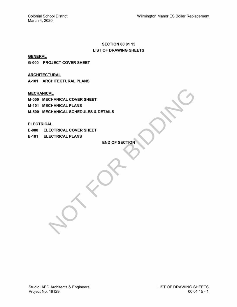
SECTION 00 01 15LIST OF DRAWING SHEETS
GENERALG-000 PROJECT COVER SHEET
ARCHITECTURALA-101 ARCHITECTURAL PLANS
MECHANICALM-000 MECHANICAL COVER SHEETM-101 MECHANICAL PLANSM-500 MECHANICAL SCHEDULES & DETAILS
ELECTRICALE-000 ELECTRICAL COVER SHEETE-101 ELECTRICAL PLANS
END OF SECTION
NOT FOR B
IDDIN
G

NOT FOR B
IDDIN
G

Wilmington Manor ES Boiler Replacement March 4, 2020
StudioJAED Architects & Engineers ADVERTISEMENT TO BID Project No. 19129 00 11 13 - 1
INVITATION TO BID
Bids will be received by Colonial School District as follows:
Bid 4-20-30 – Wilmington Manor ES Boiler Replacement on April 21, 2020 @ 2:00 PM at
the Colonial School District’s Administration Building, 318 E. Basin Road, New Castle, DE
19720. There will be a mandatory pre-bid meeting held on Monday April 6th at 9:30 AM at
Wilmington Manor Elementary School. Please sign in at the office upon arrival. A set of plans
will be available for review at the pre-bid meeting.
All RFI’s must be submitted in writing to the engineer, Studio JAED, by 5:00 PM on Tuesday,
April 14th, 2020. Please e-mail questions to Brian Zigmond at [email protected].
Contract documents may be obtained at Reprographics Center, Inc., 298 Churchmans Road,
New Castle, DE 19720, phone (302) 328-5019, upon receipt of $40.00 per set/non-refundable.
Checks are to be made payable to “StudioJAED”.
This project requires the submission of a 10% Secured Bid Deposit and a 100% Performance/
Material Labor Bond to be submitted by the successful bidder. All proposals will be opened at
the Colonial School District’s Administration Building, 318 E. Basin Rd., New Castle, DE on
April 21, 2020 @ 2:00 PM. The Owner reserves the right to reject any or all bids and to waive
any informalities therein. The time and place for the opening of bids may be extended from that
described above on not less than two calendar days’ notice by certified delivery, facsimile
machine, or other verifiable electronic means to those bidders who obtained copies of the plans
and specifications.
Pursuant to the Office of Management and Budget (OMB) “4104 Regulations for the Drug
Testing of Contractor and Subcontractor Employees Working on Large Public Works Projects”
requires that Contractors and Subcontractors who work on Large Public Works Contracts
funded all or in part with public funds implement a Mandatory Drug Testing Program. The
regulation can be downloaded from the following website:
http://regulations.delaware.gov/AdminCode/title19/4000/4100/index.shtml#TopOfPage
END OF SECTION
NOT FOR B
IDDIN
G

NOT FOR B
IDDIN
G

Wilmington Manor ES Boiler Replacement March 4, 2020
StudioJAED Architects & Engineers INSTRUCTIONS TO BIDDERS Project No. 19129 00 21 13 - 1
INSTRUCTIONS TO BIDDERS
TABLE OF ARTICLES 1. DEFINITIONS 2. BIDDER’S REPRESENTATION 3. BIDDING DOCUMENTS 4. BIDDING PROCEDURES 5. CONSIDERATION OF BIDS 6. POST-BID INFORMATION 7. PERFORMANCE BOND AND PAYMENT BOND 8. FORM OF AGREEMENT BETWEEN OWNER AND CONTRACTOR
NOT FOR B
IDDIN
G

Boiler Replacement Wilmington Manor ES March 4, 2020
INSTRUCTIONS TO BIDDERS StudioJAED Architects & Engineers 00 21 13 - 2 Project No. 19129
ARTICLE 1: GENERAL
1.1 DEFINITIONS 1.1.1 Whenever the following terms are used, their intent and meaning shall be interpreted as
follows: 1.2 STATE: The State of Delaware. 1.3 AGENCY: Contracting State Agency as noted on cover sheet. 1.4 DESIGNATED OFFICIAL: The agent authorized to act for the Agency. 1.5 BIDDING DOCUMENTS: Bidding Documents include the Bidding Requirements and the
proposed Contract Documents. The Bidding Requirements consist of the Advertisement for Bid, Invitation to Bid, Instructions to Bidders, Supplementary Instructions to Bidders (if any), General Conditions, Supplementary General Conditions, General Requirements, Special Provisions (if any), the Bid Form (including the Non-collusion Statement), and other sample bidding and contract forms. The proposed Contract Documents consist of the form of Agreement between the Owner and Contractor, as well as the Drawings, Specifications (Project Manual) and all Addenda issued prior to execution of the Contract.
1.6 CONTRACT DOCUMENTS: The Contract Documents consist of the, Instructions to
Bidders, Supplementary Instructions to Bidders (if any), General Conditions, Supplementary General Conditions, General Requirements, Special Provisions (if any), the form of agreement between the Owner and the Contractor, Drawings (if any), Specifications (Project Manual), and all addenda.
1.7 AGREEMENT: The form of the Agreement shall be AIA Document A101, Standard Form of
Agreement between Owner and Contractor where the basis of payment is a STIPULATED SUM. In the case of conflict between the instructions contained therein and the General Requirements herein, these General Requirements shall prevail.
1.8 GENERAL REQUIREMENTS (or CONDITIONS): General Requirements (or conditions)
are instructions pertaining to the Bidding Documents and to contracts in general. They contain, in summary, requirements of laws of the State; policies of the Agency and instructions to bidders.
1.9 SPECIAL PROVISIONS: Special Provisions are specific conditions or requirements
peculiar to the bidding documents and to the contract under consideration and are supplemental to the General Requirements. Should the Special Provisions conflict with the General Requirements, the Special Provisions shall prevail.
1.10 ADDENDA: Written or graphic instruments issued by the Owner/Architect prior to the
execution of the contract which modify or interpret the Bidding Documents by additions, deletions, clarifications or corrections.
1.11 BIDDER OR VENDOR: A person or entity who formally submits a Bid for the material or
Work contemplated, acting directly or through a duly authorized representative who meets the requirements set forth in the Bidding Documents.
1.12 SUB-BIDDER: A person or entity who submits a Bid to a Bidder for materials or labor, or
both for a portion of the Work.
NOT FOR B
IDDIN
G
Wilmington Manor ES Boiler Replacement March 4, 2020
StudioJAED Architects & Engineers INSTRUCTIONS TO BIDDERS Project No. 19129 00 21 13 - 3
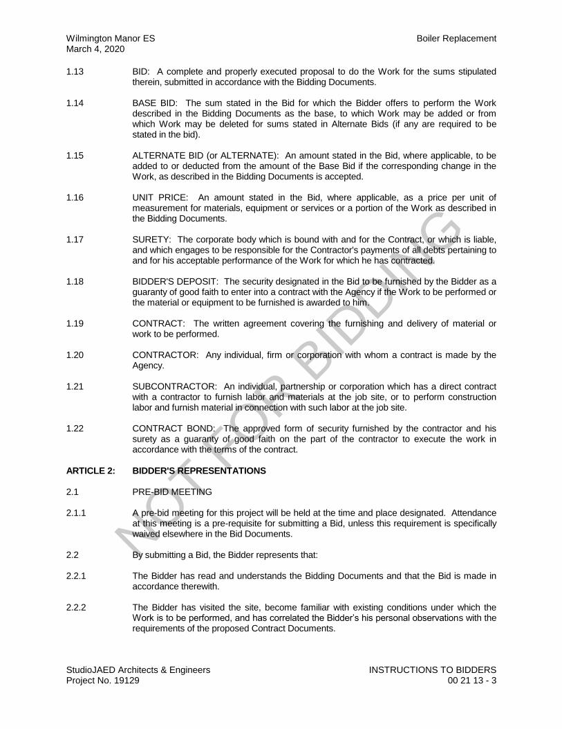
1.13 BID: A complete and properly executed proposal to do the Work for the sums stipulated therein, submitted in accordance with the Bidding Documents.
1.14 BASE BID: The sum stated in the Bid for which the Bidder offers to perform the Work
described in the Bidding Documents as the base, to which Work may be added or from which Work may be deleted for sums stated in Alternate Bids (if any are required to be stated in the bid).
1.15 ALTERNATE BID (or ALTERNATE): An amount stated in the Bid, where applicable, to be
added to or deducted from the amount of the Base Bid if the corresponding change in the Work, as described in the Bidding Documents is accepted.
1.16 UNIT PRICE: An amount stated in the Bid, where applicable, as a price per unit of
measurement for materials, equipment or services or a portion of the Work as described in the Bidding Documents.
1.17 SURETY: The corporate body which is bound with and for the Contract, or which is liable,
and which engages to be responsible for the Contractor's payments of all debts pertaining to and for his acceptable performance of the Work for which he has contracted.
1.18 BIDDER'S DEPOSIT: The security designated in the Bid to be furnished by the Bidder as a
guaranty of good faith to enter into a contract with the Agency if the Work to be performed or the material or equipment to be furnished is awarded to him.
1.19 CONTRACT: The written agreement covering the furnishing and delivery of material or
work to be performed. 1.20 CONTRACTOR: Any individual, firm or corporation with whom a contract is made by the
Agency. 1.21 SUBCONTRACTOR: An individual, partnership or corporation which has a direct contract
with a contractor to furnish labor and materials at the job site, or to perform construction labor and furnish material in connection with such labor at the job site.
1.22 CONTRACT BOND: The approved form of security furnished by the contractor and his
surety as a guaranty of good faith on the part of the contractor to execute the work in accordance with the terms of the contract.
ARTICLE 2: BIDDER'S REPRESENTATIONS 2.1 PRE-BID MEETING 2.1.1 A pre-bid meeting for this project will be held at the time and place designated. Attendance
at this meeting is a pre-requisite for submitting a Bid, unless this requirement is specifically waived elsewhere in the Bid Documents.
2.2 By submitting a Bid, the Bidder represents that: 2.2.1 The Bidder has read and understands the Bidding Documents and that the Bid is made in
accordance therewith. 2.2.2 The Bidder has visited the site, become familiar with existing conditions under which the
Work is to be performed, and has correlated the Bidder’s his personal observations with the requirements of the proposed Contract Documents.
NOT FOR B
IDDIN
G

Boiler Replacement Wilmington Manor ES March 4, 2020
INSTRUCTIONS TO BIDDERS StudioJAED Architects & Engineers 00 21 13 - 4 Project No. 19129
2.2.3 The Bid is based upon the materials, equipment, and systems required by the Bidding Documents without exception.
2.3 JOINT VENTURE REQUIREMENTS 2.3.1 For Public Works Contracts, each Joint Venturer shall be qualified and capable to complete
the Work with their own forces. 2.3.2 Included with the Bid submission, and as a requirement to bid, a copy of the executed Joint
Venture Agreement shall be submitted and signed by all Joint Venturers involved. 2.3.3 All required Bid Bonds, Performance Bonds, Material and Labor Payment Bonds must be
executed by both Joint Venturers and be placed in both of their names. 2.3.4 All required insurance certificates shall name both Joint Venturers. 2.3.5 Both Joint Venturers shall sign the Bid Form and shall submit a copy of a valid Delaware
Business License with their Bid. 2.3.6 Both Joint Venturers shall include their Federal E.I. Number with the Bid. 2.3.7 In the event of a mandatory Pre-bid Meeting, each Joint Venturer shall have a representative
in attendance. 2.3.8 Due to exceptional circumstances and for good cause shown, one or more of these
provisions may be waived at the discretion of the State. 2.4 ASSIGNMENT OF ANTITRUST CLAIMS 2.4.1 As consideration for the award and execution by the Owner of this contract, the Contractor
hereby grants, conveys, sells, assigns and transfers to the State of Delaware all of its right, title and interests in and to all known or unknown causes of action it presently has or may now or hereafter acquire under the antitrust laws of the United States and the State of Delaware, relating to the particular goods or services purchased or acquired by the Owner pursuant to this contract.
ARTICLE 3: BIDDING DOCUMENTS 3.1 COPIES OF BID DOCUMENTS 3.1.1 Bidders may obtain complete sets of the Bidding Documents from the
Architectural/Engineering firm designated in the Advertisement or Invitation to Bid in the number and for the deposit sum, if any, stated therein.
3.1.2 Bidders shall use complete sets of Bidding Documents for preparation of Bids. The issuing
Agency nor the Architect assumes no responsibility for errors or misinterpretations resulting from the use of incomplete sets of Bidding Documents.
3.1.3 Any errors, inconsistencies or omissions discovered shall be reported to the Architect
immediately. 3.1.4 The Agency and Architect may make copies of the Bidding Documents available on the
above terms for the purpose of obtaining Bids on the Work. No license or grant of use is conferred by issuance of copies of the Bidding Documents.
NOT FOR B
IDDIN
G
Wilmington Manor ES Boiler Replacement March 4, 2020
StudioJAED Architects & Engineers INSTRUCTIONS TO BIDDERS Project No. 19129 00 21 13 - 5
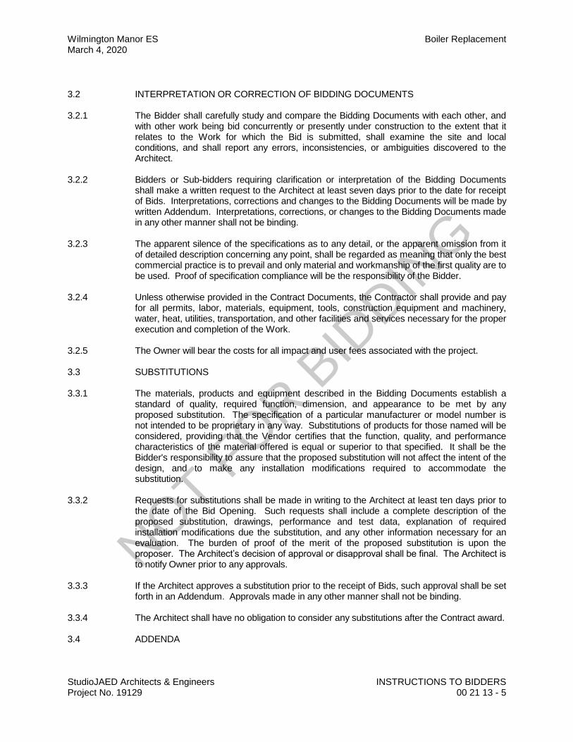
3.2 INTERPRETATION OR CORRECTION OF BIDDING DOCUMENTS 3.2.1 The Bidder shall carefully study and compare the Bidding Documents with each other, and
with other work being bid concurrently or presently under construction to the extent that it relates to the Work for which the Bid is submitted, shall examine the site and local conditions, and shall report any errors, inconsistencies, or ambiguities discovered to the Architect.
3.2.2 Bidders or Sub-bidders requiring clarification or interpretation of the Bidding Documents
shall make a written request to the Architect at least seven days prior to the date for receipt of Bids. Interpretations, corrections and changes to the Bidding Documents will be made by written Addendum. Interpretations, corrections, or changes to the Bidding Documents made in any other manner shall not be binding.
3.2.3 The apparent silence of the specifications as to any detail, or the apparent omission from it
of detailed description concerning any point, shall be regarded as meaning that only the best commercial practice is to prevail and only material and workmanship of the first quality are to be used. Proof of specification compliance will be the responsibility of the Bidder.
3.2.4 Unless otherwise provided in the Contract Documents, the Contractor shall provide and pay
for all permits, labor, materials, equipment, tools, construction equipment and machinery, water, heat, utilities, transportation, and other facilities and services necessary for the proper execution and completion of the Work.
3.2.5 The Owner will bear the costs for all impact and user fees associated with the project. 3.3 SUBSTITUTIONS 3.3.1 The materials, products and equipment described in the Bidding Documents establish a
standard of quality, required function, dimension, and appearance to be met by any proposed substitution. The specification of a particular manufacturer or model number is not intended to be proprietary in any way. Substitutions of products for those named will be considered, providing that the Vendor certifies that the function, quality, and performance characteristics of the material offered is equal or superior to that specified. It shall be the Bidder's responsibility to assure that the proposed substitution will not affect the intent of the design, and to make any installation modifications required to accommodate the substitution.
3.3.2 Requests for substitutions shall be made in writing to the Architect at least ten days prior to
the date of the Bid Opening. Such requests shall include a complete description of the proposed substitution, drawings, performance and test data, explanation of required installation modifications due the substitution, and any other information necessary for an evaluation. The burden of proof of the merit of the proposed substitution is upon the proposer. The Architect’s decision of approval or disapproval shall be final. The Architect is to notify Owner prior to any approvals.
3.3.3 If the Architect approves a substitution prior to the receipt of Bids, such approval shall be set
forth in an Addendum. Approvals made in any other manner shall not be binding. 3.3.4 The Architect shall have no obligation to consider any substitutions after the Contract award. 3.4 ADDENDA
NOT FOR B
IDDIN
G
Boiler Replacement Wilmington Manor ES March 4, 2020
INSTRUCTIONS TO BIDDERS StudioJAED Architects & Engineers 00 21 13 - 6 Project No. 19129
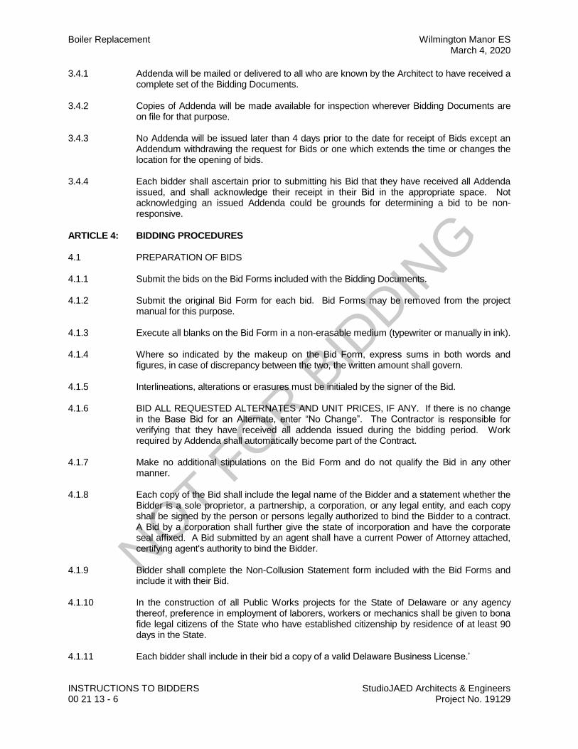
3.4.1 Addenda will be mailed or delivered to all who are known by the Architect to have received a complete set of the Bidding Documents.
3.4.2 Copies of Addenda will be made available for inspection wherever Bidding Documents are
on file for that purpose. 3.4.3 No Addenda will be issued later than 4 days prior to the date for receipt of Bids except an
Addendum withdrawing the request for Bids or one which extends the time or changes the location for the opening of bids.
3.4.4 Each bidder shall ascertain prior to submitting his Bid that they have received all Addenda
issued, and shall acknowledge their receipt in their Bid in the appropriate space. Not acknowledging an issued Addenda could be grounds for determining a bid to be non-responsive.
ARTICLE 4: BIDDING PROCEDURES 4.1 PREPARATION OF BIDS 4.1.1 Submit the bids on the Bid Forms included with the Bidding Documents. 4.1.2 Submit the original Bid Form for each bid. Bid Forms may be removed from the project
manual for this purpose. 4.1.3 Execute all blanks on the Bid Form in a non-erasable medium (typewriter or manually in ink). 4.1.4 Where so indicated by the makeup on the Bid Form, express sums in both words and
figures, in case of discrepancy between the two, the written amount shall govern. 4.1.5 Interlineations, alterations or erasures must be initialed by the signer of the Bid. 4.1.6 BID ALL REQUESTED ALTERNATES AND UNIT PRICES, IF ANY. If there is no change
in the Base Bid for an Alternate, enter “No Change”. The Contractor is responsible for verifying that they have received all addenda issued during the bidding period. Work required by Addenda shall automatically become part of the Contract.
4.1.7 Make no additional stipulations on the Bid Form and do not qualify the Bid in any other
manner. 4.1.8 Each copy of the Bid shall include the legal name of the Bidder and a statement whether the
Bidder is a sole proprietor, a partnership, a corporation, or any legal entity, and each copy shall be signed by the person or persons legally authorized to bind the Bidder to a contract. A Bid by a corporation shall further give the state of incorporation and have the corporate seal affixed. A Bid submitted by an agent shall have a current Power of Attorney attached, certifying agent's authority to bind the Bidder.
4.1.9 Bidder shall complete the Non-Collusion Statement form included with the Bid Forms and
include it with their Bid. 4.1.10 In the construction of all Public Works projects for the State of Delaware or any agency
thereof, preference in employment of laborers, workers or mechanics shall be given to bona fide legal citizens of the State who have established citizenship by residence of at least 90 days in the State.
4.1.11 Each bidder shall include in their bid a copy of a valid Delaware Business License.’
NOT FOR B
IDDIN
G
Wilmington Manor ES Boiler Replacement March 4, 2020
StudioJAED Architects & Engineers INSTRUCTIONS TO BIDDERS Project No. 19129 00 21 13 - 7
4.1.12 Each bidder shall include signed Affidavit(s) for the Bidder and each listed Subcontractor certifying compliance with OMB Regulation 4104- “Regulations for the Drug Testing of Contractor and Subcontractor Employees Working on “Large Public Works Projects.” “Large Public Works” is based upon the current threshold required for bidding Public Works as set by the Purchasing and Contracting Advisory Council.
4.2 BID SECURITY 4.2.1 All bids shall be accompanied by a deposit of either a good and sufficient bond to the
agency for the benefit of the agency, with corporate surety authorized to do business in this State, the form of the bond and the surety to be approved by the agency, or a security of the bidder assigned to the agency, for a sum equal to at least 10% of the bid plus all add alternates, or in lieu of the bid bond a security deposit in the form of a certified check, bank treasurer’s check, cashier’s check, money order, or other prior approved secured deposit assigned to the State. The bid bond need not be for a specific sum, but may be stated to be for a sum equal to 10% of the bid plus all add alternates to which it relates and not to exceed a certain stated sum, if said sum is equal to at least 10% of the bid. The Bid Bond form used shall be the standard OMB form (attached).
4.2.2 The Agency has the right to retain the bid security of Bidders to whom an award is being
considered until either a formal contract has been executed and bonds have been furnished or the specified time has elapsed so the Bids may be withdrawn or all Bids have been rejected.
4.2.3 In the event of any successful Bidder refusing or neglecting to execute a formal contract and
bond within 20 days of the awarding of the contract, the bid bond or security deposited by the successful bidder shall be forfeited.
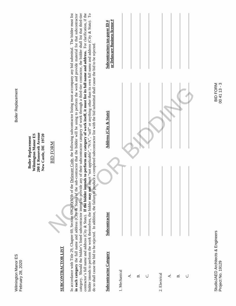
4.3 SUBCONTRACTOR LIST 4.3.1 As required by Delaware Code, Title 29, section 6962(d)(10)b, each Bidder shall submit with
their Bid a completed List of Sub-Contractors included with the Bid Form. NAME ONLY ONE SUBCONTRACTOR FOR EACH TRADE. A Bid will be considered non-responsive unless the completed list is included.
4.3.2 Provide the Name and Address for each listed subcontractor. Addresses by City, Town or
Locality, plus State, will be acceptable. 4.3.3 It is the responsibility of the Contractor to ensure that their Subcontractors are in compliance
with the provisions of this law. Also, if a Contractor elects to list themselves as a Subcontractor for any category, they must specifically name themselves on the Bid Form and be able to document their capability to act as Subcontractor in that category in accordance with this law.
4.4 EQUALITY OF EMPLOYMENT OPPORTUNITY ON PUBLIC WORKS 4.4.1 During the performance of this contract, the contractor agrees as follows:
A. The Contractor will not discriminate against any employee or applicant for employment because of race, creed, sex, color, sexual orientation, gender identity or national origin. The Contractor will take affirmative action to ensure the applicants are employed, and that employees are treated during employment, without regard to their race, creed, sex, color, sexual orientation, gender identity or national origin. Such action shall include, but not be limited to, the following: Employment, upgrading, demotion or transfer; recruitment or recruitment advertising; layoff or termination; rates of pay or other forms of compensation; and
NOT FOR B
IDDIN
G
Boiler Replacement Wilmington Manor ES March 4, 2020
INSTRUCTIONS TO BIDDERS StudioJAED Architects & Engineers 00 21 13 - 8 Project No. 19129
selection for training, including apprenticeship. The Contractor agrees to post in conspicuous places available to employees and applicants for employment notices to be provided by the contracting agency setting forth this nondiscrimination clause.
B. The Contractor will, in all solicitations or advertisements for employees placed by or
on behalf of the Contractor, state that all qualified applicants will receive consideration for employment without regard to race, creed, sex, color, sexual orientation, gender identity or national origin."
4.5 PREVAILING WAGE REQUIREMENT 4.5.1 Wage Provisions: For renovation and new construction projects whose costs exceed the
thresholds contained in Delaware Code, Title 29, Section 6960, the minimum wage rates for various classes of laborers and mechanics shall be as determined by the Department of Labor, Division of Industrial Affairs of the State of Delaware.
4.5.2 The employer shall pay all mechanics and labors employed directly upon the site of work,
unconditionally and not less often than once a week and without subsequent deduction or rebate on any account, the full amounts accrued at time of payment, computed at wage rates not less than those stated in the specifications, regardless of any contractual relationship which may be alleged to exist between the employer and such laborers and mechanics.
4.5.3 The scale of the wages to be paid shall be posted by the employer in a prominent and easily
accessible place at the site of the work. 4.5.4 Every contract based upon these specifications shall contain a stipulation that sworn payroll
information, as required by the Department of Labor, be furnished weekly. The Department of Labor shall keep and maintain the sworn payroll information for a period of 6 months from the last day of the work week covered by the payroll.
4.6 SUBMISSION OF BIDS 4.6.1 Enclose the Bid, the Bid Security, and any other documents required to be submitted with
the Bid in a sealed opaque envelope. Address the envelope to the party receiving the Bids. Identify with the project name, project number, and the Bidder's name and address. If the Bid is sent by mail, enclose the sealed envelope in a separate mailing envelope with the notation "BID ENCLOSED" on the face thereof. The State is not responsible for the opening of bids prior to bid opening date and time that are not properly marked.
4.6.2 Deposit Bids at the designated location prior to the time and date for receipt of bids indicated
in the Advertisement for Bids. Bids received after the time and date for receipt of bids will be marked “LATE BID” and returned.
4.6.3 Bidder assumes full responsibility for timely delivery at location designated for receipt of
bids. 4.6.4 Oral, telephonic or telegraphic bids are invalid and will not receive consideration. 4.6.5 Withdrawn Bids may be resubmitted up to the date and time designated for the receipt of
Bids, provided that they are then fully in compliance with these Instructions to Bidders. 4.7 MODIFICATION OR WITHDRAW OF BIDS 4.7.1 Prior to the closing date for receipt of Bids, a Bidder may withdraw a Bid by personal request
and by showing proper identification to the Architect. A request for withdraw by letter or fax, if the Architect is notified in writing prior to receipt of fax, is acceptable. A fax directing a
NOT FOR B
IDDIN
G

Wilmington Manor ES Boiler Replacement March 4, 2020
StudioJAED Architects & Engineers INSTRUCTIONS TO BIDDERS Project No. 19129 00 21 13 - 9
modification in the bid price will render the Bid informal, causing it to be ineligible for consideration of award. Telephone directives for modification of the bid price shall not be permitted and will have no bearing on the submitted proposal in any manner.
4.7.2 Bidders submitting Bids that are late shall be notified as soon as practicable and the bid
shall be returned. 4.7.3 A Bid may not be modified, withdrawn or canceled by the Bidder during a thirty (30) day
period following the time and date designated for the receipt and opening of Bids, and Bidder so agrees in submitting their Bid. Bids shall be binding for 30 days after the date of the Bid opening.
ARTICLE 5: CONSIDERATION OF BIDS 5.1 OPENING/REJECTION OF BIDS 5.1.1 Unless otherwise stated, Bids received on time will be publicly opened and will be read
aloud. An abstract of the Bids will be made available to Bidders. 5.1.2 The Agency shall have the right to reject any and all Bids. A Bid not accompanied by a
required Bid Security or by other data required by the Bidding Documents, or a Bid which is in any way incomplete or irregular is subject to rejection.
5.1.3 If the Bids are rejected, it will be done within thirty (30) calendar day of the Bid opening. 5.2 COMPARISON OF BIDS 5.2.1 After the Bids have been opened and read, the bid prices will be compared and the result of
such comparisons will be made available to the public. Comparisons of the Bids may be based on the Base Bid plus desired Alternates. The Agency shall have the right to accept Alternates in any order or combination.
5.2.2 The Agency reserves the right to waive technicalities, to reject any or all Bids, or any portion
thereof, to advertise for new Bids, to proceed to do the Work otherwise, or to abandon the Work, if in the judgment of the Agency or its agent(s), it is in the best interest of the State.
5.2.3 An increase or decrease in the quantity for any item is not sufficient grounds for an increase
or decrease in the Unit Price. 5.2.4 The prices quoted are to be those for which the material will be furnished F.O.B. Job Site
and include all charges that may be imposed during the period of the Contract. 5.2.5 No qualifying letter or statements in or attached to the Bid, or separate discounts will be
considered in determining the low Bid except as may be otherwise herein noted. Cash or separate discounts should be computed and incorporated into Unit Bid Price(s).
5.3 DISQUALIFICATION OF BIDDERS 5.3.1 An agency shall determine that each Bidder on any Public Works Contract is responsible
before awarding the Contract. Factors to be considered in determining the responsibility of a Bidder include:
A. The Bidder’s financial, physical, personnel or other resources including
Subcontracts;
NOT FOR B
IDDIN
G

Boiler Replacement Wilmington Manor ES March 4, 2020
INSTRUCTIONS TO BIDDERS StudioJAED Architects & Engineers 00 21 13 - 10 Project No. 19129
B. The Bidder’s record of performance on past public or private construction projects, including, but not limited to, defaults and/or final adjudication or admission of violations of the Prevailing Wage Laws in Delaware or any other state;
C. The Bidder’s written safety plan;
D. Whether the Bidder is qualified legally to contract with the State;
E. Whether the Bidder supplied all necessary information concerning its responsibility; and,
F. Any other specific criteria for a particular procurement, which an agency may
establish; provided however, that, the criteria be set forth in the Invitation to Bid and is otherwise in conformity with State and/or Federal law.
5.3.2 If an agency determines that a Bidder is nonresponsive and/or nonresponsible, the
determination shall be in writing and set forth the basis for the determination. A copy of the determination shall be sent to the affected Bidder within five (5) working days of said determination.
5.3.3 In addition, any one or more of the following causes may be considered as sufficient for the
disqualification of a Bidder and the rejection of their Bid or Bids. 5.3.3.1 More than one Bid for the same Contract from an individual, firm or corporation under the
same or different names. 5.3.3.2 Evidence of collusion among Bidders. 5.3.3.3 Unsatisfactory performance record as evidenced by past experience. 5.3.3.4 If the Unit Prices are obviously unbalanced either in excess or below reasonable cost
analysis values. 5.3.3.5 If there are any unauthorized additions, interlineation, conditional or alternate bids or
irregularities of any kind which may tend to make the Bid incomplete, indefinite or ambiguous as to its meaning.
5.3.3.6 If the Bid is not accompanied by the required Bid Security and other data required by the
Bidding Documents. 5.3.3.7 If any exceptions or qualifications of the Bid are noted on the Bid Form. 5.4 ACCEPTANCE OF BID AND AWARD OF CONTRACT 5.4.1 A formal Contract shall be executed with the successful Bidder within twenty (20) calendar
days after the award of the Contract. 5.4.2 Per Section 6962(d)(13) a., Title 29, Delaware Code, “The contracting agency shall award
any public works contract within thirty (30) days of the bid opening to the lowest responsive and responsible Bidder, unless the Agency elects to award on the basis of best value, in which case the election to award on the basis of best value shall be stated in the Invitation To Bid.”
NOT FOR B
IDDIN
G

Wilmington Manor ES Boiler Replacement March 4, 2020
StudioJAED Architects & Engineers INSTRUCTIONS TO BIDDERS Project No. 19129 00 21 13 - 11
5.4.3 Each Bid on any Public Works Contract must be deemed responsive by the Agency to be considered for award. A responsive Bid shall conform in all material respects to the requirements and criteria set forth in the Contract Documents and specifications.
5.4.4 The Agency shall have the right to accept Alternates in any order or combination, and to
determine the low Bidder on the basis of the sum of the Base Bid, plus accepted Alternates. 5.4.5 The successful Bidder shall execute a formal contract, submit the required Insurance
Certificate, and furnish good and sufficient bonds, unless specifically waived in the General Requirements, in accordance with the General Requirement, within twenty (20) days of official notice of contract award. The successful Bidder shall provide two business days prior to contract execution, copies of the Employee Drug Testing Program for the Bidder and all listed Subcontractors. Bonds shall be for the benefit of the Agency with surety in the amount of 100% of the total contract award. Said Bonds shall be conditioned upon the faithful performance of the contract. Bonds shall remain in affect for period of one year after the date of substantial completion.
5.4.6 If the successful Bidder fails to execute the required Contract,Bond and all required
information, as aforesaid, within twenty (20) calendar days after the date of official Notice of the Award of the Contract, their Bid guaranty shall immediately be taken and become the property of the State for the benefit of the Agency as liquidated damages, and not as a forfeiture or as a penalty. Award will then be made to the next lowest qualified Bidder of the Work or readvertised, as the Agency may decide.
5.4.7 Each bidder shall supply with its bid its taxpayer identification number (i.e., federal employer
identification number or social security number) and a copy of its Delaware business license, and should the vendor be awarded a contract, such vendor shall provide to the agency the taxpayer identification license numbers of such subcontractors. Such numbers shall be provided on the later of the date on which such subcontractor is required to be identified or the time the contract is executed. The successful Bidder shall provide to the agency to which it is contracting, within 30 days of entering into such public works contract, copies of all Delaware Business licenses of subcontractors and/or independent contractors that will perform work for such public works contract. However, if a subcontractor or independent contractor is hired or contracted more than 20 days after the Bidder entered the public works contract the Delaware Business license of such subcontractor or independent contractor shall be provided to the agency within 10 days of being contracted or hired.
5.4.8 The Bid Security shall be returned to the successful Bidder upon the execution of the formal
contract. The Bid Securities of unsuccessful bidders shall be returned within thirty (30) calendar days after the opening of the Bids.
ARTICLE 6: POST-BID INFORMATION 6.1 CONTRACTOR’S QUALIFICATION STATEMENT 6.1.1 Bidders to whom award of a Contract is under consideration shall, if requested by the
Agency, submit a properly executed AIA Document A305, Contractor’s Qualification Statement, unless such a statement has been previously required and submitted.
6.2 BUSINESS DESIGNATION FORM 6.2.1 Successful bidder shall be required to accurately complete an Office of Management and
Budget Business Designation Form for Subcontractors.
NOT FOR B
IDDIN
G

Boiler Replacement Wilmington Manor ES March 4, 2020
INSTRUCTIONS TO BIDDERS StudioJAED Architects & Engineers 00 21 13 - 12 Project No. 19129
ARTICLE 7: PERFORMANCE BOND AND PAYMENT BOND 7.1 BOND REQUIREMENTS 7.1.1 The cost of furnishing the required Bonds, that are stipulated in the Bidding Documents,
shall be included in the Bid. 7.1.2 If the Bidder is required by the Agency to secure a bond from other than the Bidder’s usual
sources, changes in cost will be adjusted as provide in the Contract Documents. 7.1.3 The Performance and Payment Bond forms used shall be the standard OMB forms
(attached). 7.2 TIME OF DELIVERY AND FORM OF BONDS 7.2.1 The bonds shall be dated on or after the date of the Contract. 7.2.2 The Bidder shall require the attorney-in-fact who executes the required bonds on behalf of
the surety to affix a certified and current copy of the power of attorney.
ARTICLE 8: FORM OF AGREEMENT BETWEEN AGENCY AND CONTRACTOR 8.1 Unless otherwise required in the Bidding Documents, the Agreement for the Work will be
written on AIA Document A101, Standard Form of Agreement Between Owner and Contractor Where the Basis of Payment is a Stipulated Sum.
END OF SECTION
NOT FOR B
IDDIN
G

Wilmington Manor ES Boiler Replacement March 4, 2020
StudioJAED Architects & Engineers BID FORM Project No. 19129 00 41 13 - 1
Boiler Replacement
Wilmington Manor ES
200 E Roosevelt Avenue
New Castle, DE 19720
BID FORM
For Bids Due: To: OMB / Division of Facilities Management
540 South DuPont Highway, Suite 1
Dover, DE 19901
Name of Bidder:
Delaware Business License No.: Taxpayer ID No.:
(A copy of Bidder’s Delaware Business License must be attached to this form.)
(Other License Nos.):
Phone No.: ( ) - Fax No.: ( ) -
The undersigned, representing that he has read and understands the Bidding Documents and that this bid is made in accordance
therewith, that he has visited the site and has familiarized himself with the local conditions under which the Work is to be performed,
and that his bid is based upon the materials, systems and equipment described in the Bidding Documents without exception, hereby
proposes and agrees to provide all labor, materials, plant, equipment, supplies, transport and other facilities required to execute the
work described by the aforesaid documents for the lump sum itemized below:
$
($ )
ALTERNATES
ALTERNATE NO. 1: Replacement of the current JCI NAE with a new JCI Tridium JACE server as defined in specification section
23 09 23, paragraph 2.03.
Add:
($ )
UNIT PRICES
There are no unit prices.
ALLOWANCES
Allowances are included as follows:
Allowance No. 1: $10,000 for general contingencies and repairs, any remaining balance of which is to be
returned to owner by credit change order at project completion. __________
(Initial)
NOT FOR B
IDDIN
G

Boiler Replacement Wilmington Manor ES March 4, 2020
BID FORM StudioJAED Architects & Engineers 00 41 13 - 2 Project No. 19129
Boiler Replacement
Wilmington Manor ES
200 E Roosevelt Avenue
New Castle, DE 19720
BID FORM
I/We acknowledge Addendums numbered and the price(s) submitted include any cost/schedule impact they may have.
This bid shall remain valid and cannot be withdrawn for thirty (30) days from the date of opening of bids (60 days for School Districts
and Department of Education), and the undersigned shall abide by the Bid Security forfeiture provisions. Bid Security is attached to
this Bid.
The Owner shall have the right to reject any or all bids, and to waive any informality or irregularity in any bid received.
This bid is based upon work being accomplished by the Sub-Contractors named on the list attached to this bid.
Should I/We be awarded this contract, I/We pledge to achieve substantial completion of all the work within calendar days of
the Notice to Proceed.
The undersigned represents and warrants that he has complied and shall comply with all requirements of local, state, and national
laws; that no legal requirement has been or shall be violated in making or accepting this bid, in awarding the contract to him or in the
prosecution of the work required; that the bid is legal and firm; that he has not, directly or indirectly, entered into any agreement,
participated in any collusion, or otherwise taken action in restraint of free competitive bidding.
Upon receipt of written notice of the acceptance of this Bid, the Bidder shall, within twenty (20) calendar days, execute the agreement
in the required form and deliver the Contract Bonds, and Insurance Certificates, required by the Contract Documents.
I am / We are an Individual / a Partnership / a Corporation
By Trading as
(Individual’s / General Partner’s / Corporate Name)
(State of Corporation)
Business Address:
Witness: By: ( Authorized Signature )
(SEAL)
( Title )
Date:
ATTACHMENTS Sub-Contractor List
Non-Collusion Statement
Affidavit(s) of Employee Drug Testing Program
Bid Security
(Others as Required by Project Manuals)
NOT FOR B
IDDIN
G
Wilm
ingto
n M
an
or
ES
Bo
iler
Repla
cem
ent
Febru
ary
28
, 20
20
S
tud
ioJA
ED
Arc
hitects
& E
ngin
eers
BID
FO
RM
P
roje
ct N
o.
191
29
00 4
1 1
3 -
3
Bo
iler
Rep
lace
men
t
Wil
min
gto
n M
an
or
ES
20
0 E
Ro
ose
vel
t A
ven
ue
New
Ca
stle
, D
E
19
72
0
BID
FO
RM
SU
BC
ON
TR
AC
TO
R L
IST
In a
cco
rdan
ce w
ith T
itle
29
, C
hap
ter
69
, S
ecti
on
69
62
(d)(
10
)b o
f th
e D
elaw
are
Co
de,
the f
oll
ow
ing s
ub
contr
acto
r li
stin
g m
ust
acc
om
pan
y a
ny b
id s
ub
mit
tal.
T
he
bid
der
must
lis
t
in e
ach
ca
teg
ory
the
full
nam
e and
ad
dre
ss (
Cit
y &
Sta
te)
of
the
sub
-co
ntr
acto
r th
at t
he
bid
der
wil
l b
e usi
ng t
o p
erfo
rm t
he
wo
rk a
nd
pro
vid
e m
ater
ial
for
that
sub
contr
acto
r
cate
go
ry.
Sho
uld
the
bid
der
’s l
iste
d s
ub
contr
acto
r in
tend
to
pro
vid
e an
y o
f th
eir
sub
contr
acto
r ca
tego
ry o
f w
ork
thro
ug
h a
th
ird
-tie
r co
ntr
acto
r, t
he
bid
der
shal
l li
st t
hat
thir
d-t
ier
contr
acto
r’s
full
nam
e a
nd
ad
dre
ss (
Cit
y &
Sta
te).
If
th
e b
idd
er i
nte
nd
s to
per
form
an
y c
ate
go
ry o
f w
ork
its
elf,
it
mu
st l
ist
its
full
na
me
an
d a
dd
ress
. F
or
clar
ific
atio
n,
if t
he
bid
der
inte
nd
s to
per
form
the
wo
rk t
hem
selv
es,
the
bid
der
ma
y n
ot
inse
rt “
no
t ap
pli
cab
le”,
“N
/A”,
“se
lf”
or
anyth
ing
oth
er t
han i
ts o
wn
full
nam
e and
ad
dre
ss (
Cit
y &
Sta
te).
T
o
do
so
shal
l ca
use
the
bid
to
be
reje
cted
. I
n a
dd
itio
n,
the
fail
ure
to
pro
duce
a c
om
ple
ted
sub
contr
acto
r li
st w
ith t
he
bid
su
bm
itta
l sh
all
cau
se t
he
bid
to
be
reje
cted
.
Su
bco
ntr
act
or
Ca
teg
ory
S
ub
con
tra
cto
r
Ad
dre
ss (
Cit
y &
Sta
te)
Su
bco
ntr
act
ors
tax-p
ayer
ID
#
or
Del
aw
are
Bu
sin
ess
lice
nse
#
1.
Mec
han
ical
A
.
B
.
C
.
2.
Ele
ctri
cal
A
.
B
.
C
.
NOT FOR B
IDDIN
G

Boiler Replacement Wilmington Manor ES March 4, 2020
BID FORM StudioJAED Architects & Engineers 00 41 13 - 4 Project No. 19129
Boiler Replacement
Wilmington Manor ES
200 E Roosevelt Avenue
New Castle, DE 19720
AFFIDAVIT
OF
CONTRACTOR QUALIFICATIONS
We hereby certify that we will abide by the contractor’s qualifications outlined in the construction bid specifications for the duration
of the contract term.
In accordance with Title 29, Chapter 69, Section 6962(d)(10)b.3 of the Delaware Code, after a contract has been awarded the
successful bidder shall not substitute another subcontractor whose name was submitted on the Subcontractor Form except for the
reasons in the statute and not without written consent from the awarding agency. Failure to utilize the subcontractors on the list will
subject the successful bidder to penalties as outlined in the General Requirements Section 5.2 of the contract.
Contractor Name:
Contractor Address:
Authorized Representative (typed or printed):
Authorized Representative (signature):
Title:
Sworn to and Subscribed before me this day of 20 .
My Commission expires . NOTARY PUBLIC .
THIS PAGE MUST BE SIGNED AND NOTARIZED FOR YOUR BID TO BE CONSIDERED.
NOT FOR B
IDDIN
G
Wilmington Manor ES Boiler Replacement February 28, 2020
StudioJAED Architects & Engineers BID FORM Project No. 19129 00 41 13 - 5
Boiler Replacement
Wilmington Manor ES
200 E Roosevelt Avenue
New Castle, DE 19720
BID FORM
NON-COLLUSION STATEMENT
This is to certify that the undersigned bidder has neither directly nor indirectly, entered into any agreement, participated in any
collusion or otherwise taken any action in restraint of free competitive bidding in connection with this proposal submitted this date to
the Office of Management and Budget, Division of Facilities Management.
All the terms and conditions have been thoroughly examined and are understood.
NAME OF BIDDER:
AUTHORIZED REPRESENTATIVE
(TYPED):
AUTHORIZED REPRESENTATIVE
(SIGNATURE):
TITLE:
ADDRESS OF BIDDER:
E-MAIL: ______________________________________________________________
PHONE NUMBER:
Sworn to and Subscribed before me this day of 20 .
My Commission expires . NOTARY PUBLIC .
THIS PAGE MUST BE SIGNED AND NOTARIZED FOR YOUR BID TO BE CONSIDERED.
NOT FOR B
IDDIN
G

Boiler Replacement Wilmington Manor ES March 4, 2020
BID FORM StudioJAED Architects & Engineers 00 41 13 - 6 Project No. 19129
Boiler Replacement
Wilmington Manor ES
200 E Roosevelt Avenue
New Castle, DE 19720
AFFIDAVIT
OF
EMPLOYEE DRUG TESTING PROGRAM
4104 Regulations for the Drug Testing of Contractor and Subcontractor Employees Working on Large Public Works Projects requires
that Contractors and Subcontractors implement a program of mandatory drug testing for Employees who work on Large Public Works
Contracts funded all or in part with public funds.
We hereby certify that we have in place or will implement during the entire term of the contract a Mandatory Drug Testing Program
for our employees on the jobsite, including subcontractors that complies with this regulation:
Contractor/Subcontractor Name:
Contractor/Subcontractor Address:
Authorized Representative (typed or printed):
Authorized Representative (signature):
Title:
Sworn to and Subscribed before me this day of 20 .
My Commission expires . NOTARY PUBLIC .
THIS PAGE MUST BE SIGNED AND NOTARIZED FOR YOUR BID TO BE CONSIDERED.
END OF SECTION
NOT FOR B
IDDIN
G

Wilmington Manor ES Boiler Replacement March 4, 2020
StudioJAED Architects & Engineers ALLOWANCE AUTHORIZATION Project No. 19129 00 41 14 - 1
ALLOWANCE AUTHORIZATION
Project: Wilmington Manor ES Boiler Replacement Architect: StudioJAED Architects & Engineers Project No. 19129 Contractor: AAA No.: Initiation Date: The Allowance is allocated as follows: Allowance No. 1: $10,000 for General Contingencies and Repairs. Total original Contract Allowance was: $ 10,000.00 Amount of Contract Allowance Access previously authorized: $ Adjusted Contract Allowance prior to this authorization is: $ The amount of available Allowance will Decrease by this Access Authorization: $ The remaining Contract Allowance, after this Access Authorization will be: $ Recommended by: Architect By (Signature): ________________________________ Date: _______________________________________ Accepted by: Approved by: Contractor Owner By (Signature): __________________________ By (Signature): _____________________________ Date: ________________________________ Date: _____________________________________
NOT FOR B
IDDIN
G

NOT FOR B
IDDIN
G

Wilmington Manor ES Boiler Replacement March 4, 2020
StudioJAED Architects & Engineers BID BOND Project No. 19129 00 43 13 - 1
STATE OF DELAWARE
OFFICE OF MANAGEMENT AND BUDGET
BID BOND
TO ACCOMPANY PROPOSAL
(Not necessary if security is used)
KNOW ALL MEN BY THESE PRESENTS That:
of in the County of
and State of as Principal, and
of in the County of
and State of as Surety, legally authorized to do business in the State of Delaware
(“State”), are held and firmly unto the State in the sum of
Dollars ($ ), or percent not to exceed
Dollars ($ )
of amount of bid on Contract, to be paid to the State for the use and benefit of OMB / Division of Facilities
Management for which payment well and truly to be made, we do bind ourselves, our and each of our heirs,
executors, administrators, and successors, jointly and severally for and in the whole firmly by these presents.
NOW THE CONDITION OF THIS OBLIGATION IS SUCH That if the above bonded Principal
who has submitted to the Colonial School District a certain proposal to enter into this contract for the
furnishing of certain material and/or services within the State, shall be awarded this Contract, and if said
Principal shall well and truly enter into and execute this Contract as may be required by the terms of this
Contract and approved by the Colonial School District this Contract to be entered into within twenty days
after the date of official notice of the award thereof in accordance with the terms of said proposal, then this
obligation shall be void or else to be and remain in full force and virtue.
Sealed with seal and dated this day of in the year of our Lord two
thousand and (20 ).
SEALED, AND DELIVERED IN THE
Presence of
Name of Bidder (Organization)
Corporate By:
Seal Authorized Signature
Attest
Title
Name of Surety
Witness: By:
Title
NOT FOR B
IDDIN
G

NOT FOR B
IDDIN
G

Wilmington Manor ES Boiler Replacement March 4, 2020
StudioJAED Architects & Engineers STANDARD FORM OF AGREEMENT OWN/ER/CONTRACTOR Project No. 19129 00 52 13 - 1
STANDARD FORM OF AGREEMENT BETWEEN OWNER AND CONTRACTOR A101-2017
The contract to be utilized on this project shall be the “Standard Form of Agreement Between Owner and Contractor” AIA Document A101-2017, including AIA Document A101 – 2017 Exhibit A, as well as Supplements to A101-2017 and Exhibit A and the State of Delaware’s General Requirements.
NOT FOR B
IDDIN
G

NOT FOR B
IDDIN
G

NOT FOR B
IDDIN
G

NOT FOR B
IDDIN
G

NOT FOR B
IDDIN
G
NOT FOR B
IDDIN
G

NOT FOR B
IDDIN
G

NOT FOR B
IDDIN
G

NOT FOR B
IDDIN
G

NOT FOR B
IDDIN
G

Wilmington Manor ES Boiler Replacement March 4, 2020
StudioJAED Architects & Engineers SUPPLEMENT TO AGREEMENT Project No. 19129 BETWEEN OWNER/CONTRACTOR 00 54 13 - 1
SUPPLEMENT TO AGREEMENT BETWEEN OWNER AND CONTRACTOR A101-2017
The following supplements modify the “Standard Form of Agreement Between Owner and Constructor,” AIA Document A101-2017. Where a portion of the Standard Form of Agreement is modified or deleted by the following, the unaltered portions of the Standard Form of Agreement shall remain in effect.
ARTICLE 3: DATE OF COMMENCEMENT AND SUBSTANTIAL COMPLETION 3.1 Delete paragraph 3.1 in its entirety and replace with the following:
“The date of Commencement of the Work shall be a date set forth in a notice to proceed issued by the Owner.”
ARTICLE 5: PAYMENTS 5.1 PROGRESS PAYMENTS 5.1.3 Delete paragraph 5.1.3 in its entirety and replace with the following:
“Provided that a valid Application for Payment is received by the Architect that meets all requirements of the Contract, payment shall be made by the Owner not later than 30 days after the Owner receives the valid Application for Payment.”
5.3 Insert the interest rate of “1% per month not to exceed 12% per annum.” ARTICLE 6: DISPUTE RESOLUTION 6.2 BINDING DISPUTE RESOLUTION
Check Other – and add the following sentence:
"Any remedies available in law or in equity." ARTICLE 7: TERMINATION or SUSPENSION 7.1.1 Delete paragraph 7.1.1 in its entirety.
ARTICLE 8: MISCELLANEOUS PROVISIONS
8.4 Delete paragraph 8.4 in its entirety and replace with the following:
“The Contractor’s representative shall not be changed without ten days written notice to the Owner.”
END OF SECTION
NOT FOR B
IDDIN
G

NOT FOR B
IDDIN
G
Wilmington Manor ES Boiler Replacement March 4, 2020
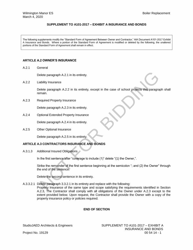
StudioJAED Architects & Engineers SUPPLEMENT TO A101-2017 – EXHIBIT A INSURANCE AND BONDS Project No. 19129 00 54 14 - 1
SUPPLEMENT TO A101-2017 – EXHIBIT A INSURANCE AND BONDS
The following supplements modify the “Standard Form of Agreement Between Owner and Contractor,” AIA Document A101-2017 Exhibit A Insurance and Bonds. Where a portion of the Standard Form of Agreement is modified or deleted by the following, the unaltered portions of the Standard Form of Agreement shall remain in effect.
ARTICLE A.2 OWNER’S INSURANCE A.2.1 General Delete paragraph A.2.1 in its entirety. A.2.2 Liability Insurance Delete paragraph A.2.2 in its entirety, except in the case of school projects this paragraph shall
remain. A.2.3 Required Property Insurance Delete paragraph A.2.3 in its entirety. A.2.4 Optional Extended Property Insurance Delete paragraph A.2.4 in its entirety. A.2.5 Other Optional Insurance Delete paragraph A.2.5 in its entirety. ARTICLE A.3 CONTRACTORS INSURANCE AND BONDS A.3.1.3 Additional Insured Obligations In the first sentence after “coverage to include (1)” delete “(1) the Owner,”. Strike the remainder of the first sentence beginning at the semicolon “; and (2) the Owner” through
the end of the sentence. Delete the second sentence in its entirety. A.3.3.2.1 Delete paragraph 3.3.2.1 in its entirety and replace with the following: Property Insurance of the same type and scope satisfying the requirements identified in Section
A.2.3, The Contractor shall comply with all obligations of the Owner under A.2.3 except to the extent provided below. Upon request, the Contractor shall provide the Owner with a copy of the property insurance policy or policies required.
END OF SECTION
NOT FOR B
IDDIN
G

NOT FOR B
IDDIN
G

NOT FOR B
IDDIN
G

NOT FOR B
IDDIN
G

NOT FOR B
IDDIN
G

NOT FOR B
IDDIN
G

NOT FOR B
IDDIN
G

NOT FOR B
IDDIN
G

NOT FOR B
IDDIN
G

NOT FOR B
IDDIN
G

Wilmington Manor ES Boiler Replacement March 4, 2020
StudioJAED Architects & Engineers PERFORMANCE BOND Project No. 19129 00 61 13.13 - 1
STATE OF DELAWARE
OFFICE OF MANAGEMENT AND BUDGET
PERFORMANCE BOND
Bond Number: ___________________
KNOW ALL PERSONS BY THESE PRESENTS, that we, ______________________, as principal
(“Principal”), and ______________________, a ______________________ corporation, legally
authorized to do business in the State of Delaware, as surety (“Surety”), are held and firmly bound
unto the State of Delaware Office of Management & Budget (“Owner”), in the amount of
_________________ ($___________), to be paid to Owner, for which payment well and truly to be
made, we do bind ourselves, our and each and every of our heirs, executors, administrations,
successors and assigns, jointly and severally, for and in the whole, firmly by these presents.
Sealed with our seals and dated this __________ day of ____________, 20__.
NOW THE CONDITION OF THIS OBLIGATION IS SUCH, that if Principal, who has been
awarded by Owner that certain contract known as ______________________________________
dated the __________ day of ____________, 20__ (the “Contract”), which Contract is incorporated
herein by reference, shall well and truly provide and furnish all materials, appliances and tools and
perform all the work required under and pursuant to the terms and conditions of the Contract and
the Contract Documents (as defined in the Contract) or any changes or modifications thereto made
as therein provided, shall make good and reimburse Owner sufficient funds to pay the costs of
completing the Contract that Owner may sustain by reason of any failure or default on the part of
Principal, and shall also indemnify and save harmless Owner from all costs, damages and
expenses arising out of or by reason of the performance of the Contract and for as long as provided
by the Contract; then this obligation shall be void, otherwise to be and remain in full force and
effect.
Surety, for value received, hereby stipulates and agrees, if requested to do so by Owner, to fully
perform and complete the work to be performed under the Contract pursuant to the terms,
conditions and covenants thereof, if for any cause Principal fails or neglects to so fully perform and
complete such work.
Surety, for value received, for itself and its successors and assigns, hereby stipulates and agrees that
the obligation of Surety and its bond shall be in no way impaired or affected by any extension of
time, modification, omission, addition or change in or to the Contract or the work to be performed
thereunder, or by any payment thereunder before the time required therein, or by any waiver of any
provisions thereof, or by any assignment, subletting or other transfer thereof or of any work to be
performed or any monies due or to become due thereunder; and Surety hereby waives notice of any
and all such extensions, modifications, omissions, additions, changes, payments, waivers,
assignments, subcontracts and transfers and hereby expressly stipulates and agrees that any and all
things done and omitted to be done by and in relation to assignees, subcontractors, and other
NOT FOR B
IDDIN
G
Boiler Replacement Wilmington Manor ES March 4, 2020
PERFORMANCE BOND StudioJAED Architects & Engineers 00 61 13.13 - 2 Project No. 19129
transferees shall have the same effect as to Surety as though done or omitted to be done by or in
relation to Principal.
Surety hereby stipulates and agrees that no modifications, omissions or additions in or to the terms
of the Contract shall in any way whatsoever affect the obligation of Surety and its bond.
Any proceeding, legal or equitable, under this Bond may be brought in any court of competent
jurisdiction in the State of Delaware. Notices to Surety or Contractor may be mailed or delivered
to them at their respective addresses shown below.
IN WITNESS WHEREOF, Principal and Surety have hereunto set their hand and seals, and such
of them as are corporations have caused their corporate seal to be hereto affixed and these presents
to be signed by their duly authorized officers, the day and year first above written.
PRINCIPAL
Name:
Witness or Attest: Address:
By: (SEAL)
Name: Name:
Title:
(Corporate Seal)
SURETY
Name:
Witness or Attest: Address:
By: (SEAL)
Name: Name:
Title:
(Corporate Seal)
NOT FOR B
IDDIN
G

Wilmington Manor ES Boiler Replacement March 4, 2020
StudioJAED Architects & Engineers PAYMENT BOND Project No. 19129 00 61 13.16 - 1
STATE OF DELAWARE
OFFICE OF MANAGEMENT AND BUDGET
PAYMENT BOND
Bond Number: ___________________
KNOW ALL PERSONS BY THESE PRESENTS, that we, ____________________, as principal
(“Principal”), and __________________, a ____________________ corporation, legally
authorized to do business in the State of Delaware, as surety (“Surety”), are held and firmly bound
unto the State of Delaware Office of Management & Budget (“Owner”), in the amount of
_________________ ($___________), to be paid to Owner, for which payment well and truly to be
made, we do bind ourselves, our and each and every of our heirs, executors, administrations,
successors and assigns, jointly and severally, for and in the whole firmly by these presents.
Sealed with our seals and dated this _____________ day of____________, 20__.
NOW THE CONDITION OF THIS OBLIGATION IS SUCH, that if Principal, who has been
awarded by Owner that certain contract known as Contract No. ___________________________
dated the _______ day of _____________, 20__ (the “Contract”), which Contract is incorporated
herein by reference, shall well and truly pay all and every person furnishing materials or performing
labor or service in and about the performance of the work under the Contract, all and every sums of
money due him, her, them or any of them, for all such materials, labor and service for which
Principal is liable, shall make good and reimburse Owner sufficient funds to pay such costs in the
completion of the Contract as Owner may sustain by reason of any failure or default on the part of
Principal, and shall also indemnify and save harmless Owner from all costs, damages and
expenses arising out of or by reason of the performance of the Contract and for as long as provided
by the Contract; then this obligation shall be void, otherwise to be and remain in full force and
effect.
Surety, for value received, for itself and its successors and assigns, hereby stipulates and agrees that
the obligation of Surety and its bond shall be in no way impaired or affected by any extension of
time, modification, omission, addition or change in or to the Contract or the work to be performed
thereunder, or by any payment thereunder before the time required therein, or by any waiver of any
provisions thereof, or by any assignment, subletting or other transfer thereof or of any work to be
performed or any monies due or to become due thereunder; and Surety hereby waives notice of any
and all such extensions, modifications, omissions, additions, changes, payments, waivers,
assignments, subcontracts and transfers and hereby expressly stipulates and agrees that any and all
things done and omitted to be done by and in relation to assignees, subcontractors, and other
transferees shall have the same effect as to Surety as though done or omitted to be done by or in
relation to Principal.
Surety hereby stipulates and agrees that no modifications, omission or additions in or to the terms
of the Contract shall in any way whatsoever affect the obligation of Surety and its bond.
NOT FOR B
IDDIN
G
Boiler Replacement Wilmington Manor ES March 4, 2020
PAYMENT BOND StudioJAED Architects & Engineers 00 61 13.16 - 2 Project No. 19129
Any proceeding, legal or equitable, under this Bond may be brought in any court of competent
jurisdiction in the State of Delaware. Notices to Surety or Contractor may be mailed or delivered
to them at their respective addresses shown below.
IN WITNESS WHEREOF, Principal and Surety have hereunto set their hand and seals, and such
of them as are corporations have caused their corporate seal to be hereto affixed and these presents
to be signed by their duly authorized officers, the day and year first above written.
PRINCIPAL
Name:
Witness or Attest: Address:
By: (SEAL)
Name: Name:
Title:
(Corporate Seal)
SURETY
Name:
Witness or Attest: Address:
By: (SEAL)
Name: Name:
Title:
(Corporate Seal)
NOT FOR B
IDDIN
G

Wilmington Manor ES Boiler Replacement March 4, 2020
StudioJAED Architects & Engineers APPLICATION AND CERTIFICATE FOR PAYMENT FORMS Project No. 19129 00 62 76 - 1
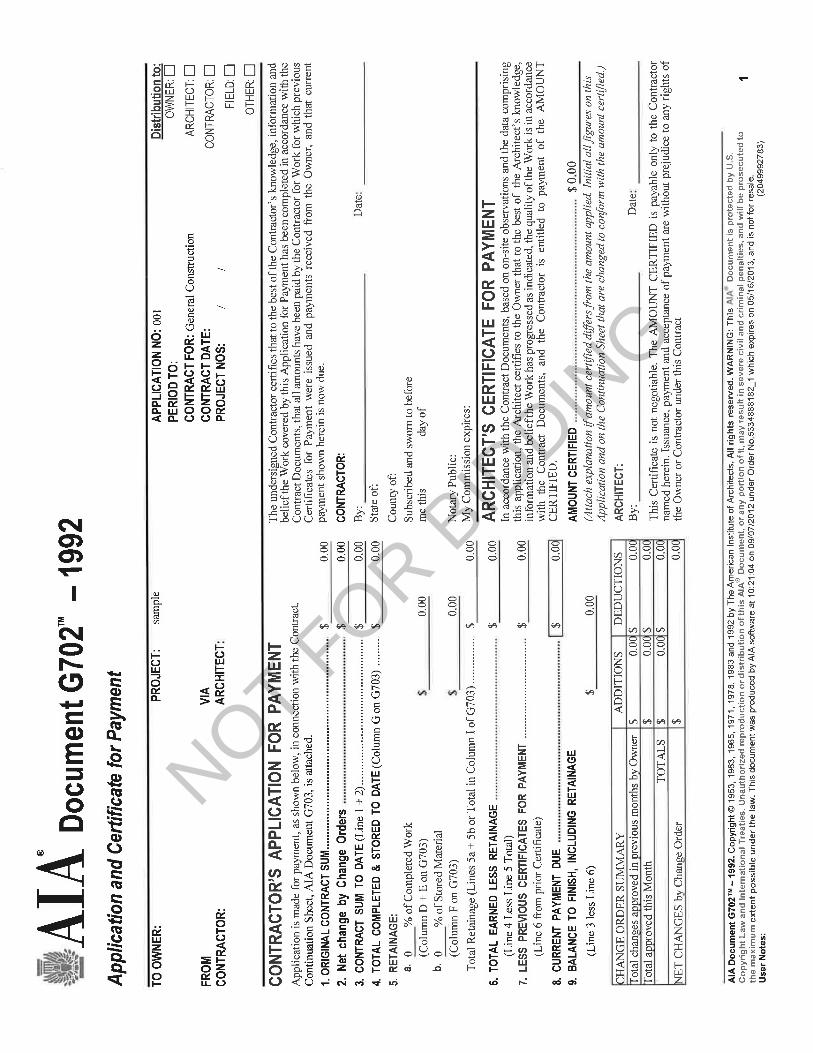
APPLICATION AND CERTIFICATE FOR PAYMENT FORMS G702-1992 & G703-1992 The application and certificate for payment forms to be utilized on this project shall be the “Application and Certificate for Payment Forms” AIA G702-1992 and AIA G703-1992.
NOT F
OR BID
DING

NOT FOR B
IDDIN
G
NOT FOR B
IDDIN
G

NOT FOR B
IDDIN
G

Wilmington Manor ES Boiler Replacement March 4, 2020
StudioJAED Architects & Engineers CLOSEOUT DOCUMENT CHECKLIST Project No. 19129 00 65 01 - 1
Closeout Document Checklist
Project:
Date:
1. 2 original Form G704 Substantial Completion
2. 2 original Form G706 Affidavit of Payment of Debts and Claims
3. 2 original Form 706A Release of Liens Contractor / Subcontractor
4. 2 original Form 707 Consent of Surety Company
5. 3 original Final Payment App
6. Meeting Minutes
7. General Correspondence
8. Certificate of Occupancy
9. Environmental Certificates
10. 2 original of Warranties ( Letter of Guarantee and Warranty Info)
11. 2 O&M Manuals
12. 2 Hard Copy of As-Built Drawings
13. 2 sets of drawing discs. Updated CAD files
14. Occupancy Permits
15. Test & Balancing Reports
16. Field Reports/Inspection Reports
17. Pest Control Final Inspection Report & Warranty (Slabs over 400SF)
18. 2 original Substantial Completion Form
19. 2 sets of Record Shop Drawings and submittals
20. Affidavit of Discharge of State Tax Liability
21. Copy of completed final punch list signed off on by Owner’s Rep
22. Punch list Closeout Letter.
NOT FOR B
IDDIN
G

NOT FOR B
IDDIN
G
Wilmington Manor ES Boiler Replacement March 4, 2020
StudioJAED Architects & Engineers GENERAL CONDITIONS TO THE CONTRACT Project No. 19129 00 72 13 - 1
GENERAL CONDITIONS TO THE CONTRACT The General Conditions of this Contract are as stated in the American Institute of Architects Document AIA A201 (2017 Edition) entitled General Conditions of the Contract for Construction and is part of this project manual as if herein written in full.
END OF SECTION
NOT FOR B
IDDIN
G

NOT FOR B
IDDIN
G

Document A201TM – 2017General Conditions of the Contract for Construction
Init.
/
AIA Document A201™ – 2017. Copyright © 1911, 1915, 1918, 1925, 1937, 1951, 1958, 1961, 1963, 1966, 1970, 1976, 1987, 1997, 2007 and 2017 by The American Institute of Architects. All rights reserved. WARNING: This AIA® Document is protected by U.S. Copyright Law and International Treaties. Unauthorized reproduction or distribution of this AIA® Document, or any portion of it, may result in severe civil and criminal penalties, and will be prosecuted to the maximum extent possible under the law. This document was produced by AIA software at 11:54:08 ET on 01/08/2019 under Order No.1716186716 which expires on 08/15/2019, and is not for resale.User Notes: (1447379532)
1
ADDITIONS AND DELETIONS: The author of this document has added information needed for its completion. The author may also have revised the text of the original AIA standard form. An Additions and Deletions Report that notes added information as well as revisions to the standard form text is available from the author and should be reviewed. A vertical line in the left margin of this document indicates where the author has added necessary information and where the author has added to or deleted from the original AIA text.
This document has important legal consequences. Consultation with an attorney is encouraged with respect to its completion or modification.
For guidance in modifying this document to include supplementary conditions, see AIA Document A503™, Guide for Supplementary Conditions.
for the following PROJECT:(Name and location or address)
Sample
THE OWNER:(Name, legal status and address)
THE ARCHITECT:(Name, legal status and address)
TABLE OF ARTICLES
1 GENERAL PROVISIONS
2 OWNER
3 CONTRACTOR
4 ARCHITECT
5 SUBCONTRACTORS
6 CONSTRUCTION BY OWNER OR BY SEPARATE CONTRACTORS
7 CHANGES IN THE WORK
8 TIME
9 PAYMENTS AND COMPLETION
10 PROTECTION OF PERSONS AND PROPERTY
11 INSURANCE AND BONDS
12 UNCOVERING AND CORRECTION OF WORK
13 MISCELLANEOUS PROVISIONS
14 TERMINATION OR SUSPENSION OF THE CONTRACT
15 CLAIMS AND DISPUTES
NOT FOR B
IDDIN
G

Init.
/
AIA Document A201™ – 2017. Copyright © 1911, 1915, 1918, 1925, 1937, 1951, 1958, 1961, 1963, 1966, 1970, 1976, 1987, 1997, 2007 and 2017 by The American Institute of Architects. All rights reserved. WARNING: This AIA® Document is protected by U.S. Copyright Law and International Treaties. Unauthorized reproduction or distribution of this AIA® Document, or any portion of it, may result in severe civil and criminal penalties, and will be prosecuted to the maximum extent possible under the law. This document was produced by AIA software at 11:54:08 ET on 01/08/2019 under Order No.1716186716 which expires on 08/15/2019, and is not for resale.User Notes: (1447379532)
2
INDEX(Topics and numbers in bold are Section headings.)
Acceptance of Nonconforming Work9.6.6, 9.9.3, 12.3Acceptance of Work9.6.6, 9.8.2, 9.9.3, 9.10.1, 9.10.3, 12.3Access to Work3.16, 6.2.1, 12.1Accident Prevention10Acts and Omissions3.2, 3.3.2, 3.12.8, 3.18, 4.2.3, 8.3.1, 9.5.1, 10.2.5, 10.2.8, 13.3.2, 14.1, 15.1.2, 15.2Addenda1.1.1Additional Costs, Claims for3.7.4, 3.7.5, 10.3.2, 15.1.5Additional Inspections and Testing9.4.2, 9.8.3, 12.2.1, 13.4Additional Time, Claims for3.2.4, 3.7.4, 3.7.5, 3.10.2, 8.3.2, 15.1.6Administration of the Contract3.1.3, 4.2, 9.4, 9.5Advertisement or Invitation to Bid1.1.1Aesthetic Effect4.2.13Allowances3.8Applications for Payment4.2.5, 7.3.9, 9.2, 9.3, 9.4, 9.5.1, 9.5.4, 9.6.3, 9.7, 9.10Approvals2.1.1, 2.3.1, 2.5, 3.1.3, 3.10.2, 3.12.8, 3.12.9, 3.12.10.1, 4.2.7, 9.3.2, 13.4.1Arbitration8.3.1, 15.3.2, 15.4 ARCHITECT4Architect, Definition of4.1.1Architect, Extent of Authority2.5, 3.12.7, 4.1.2, 4.2, 5.2, 6.3, 7.1.2, 7.3.4, 7.4, 9.2, 9.3.1, 9.4, 9.5, 9.6.3, 9.8, 9.10.1, 9.10.3, 12.1, 12.2.1, 13.4.1, 13.4.2, 14.2.2, 14.2.4, 15.1.4, 15.2.1Architect, Limitations of Authority and Responsibility2.1.1, 3.12.4, 3.12.8, 3.12.10, 4.1.2, 4.2.1, 4.2.2, 4.2.3, 4.2.6, 4.2.7, 4.2.10, 4.2.12, 4.2.13, 5.2.1, 7.4, 9.4.2, 9.5.4, 9.6.4, 15.1.4, 15.2Architect’s Additional Services and Expenses2.5, 12.2.1, 13.4.2, 13.4.3, 14.2.4Architect’s Administration of the Contract3.1.3, 3.7.4, 15.2, 9.4.1, 9.5Architect’s Approvals2.5, 3.1.3, 3.5, 3.10.2, 4.2.7
Architect’s Authority to Reject Work3.5, 4.2.6, 12.1.2, 12.2.1Architect’s Copyright1.1.7, 1.5Architect’s Decisions3.7.4, 4.2.6, 4.2.7, 4.2.11, 4.2.12, 4.2.13, 4.2.14, 6.3, 7.3.4, 7.3.9, 8.1.3, 8.3.1, 9.2, 9.4.1, 9.5, 9.8.4, 9.9.1, 13.4.2, 15.2Architect’s Inspections3.7.4, 4.2.2, 4.2.9, 9.4.2, 9.8.3, 9.9.2, 9.10.1, 13.4Architect’s Instructions3.2.4, 3.3.1, 4.2.6, 4.2.7, 13.4.2Architect’s Interpretations4.2.11, 4.2.12Architect’s Project Representative4.2.10Architect’s Relationship with Contractor1.1.2, 1.5, 2.3.3, 3.1.3, 3.2.2, 3.2.3, 3.2.4, 3.3.1, 3.4.2, 3.5, 3.7.4, 3.7.5, 3.9.2, 3.9.3, 3.10, 3.11, 3.12, 3.16, 3.18, 4.1.2, 4.2, 5.2, 6.2.2, 7, 8.3.1, 9.2, 9.3, 9.4, 9.5, 9.7, 9.8, 9.9, 10.2.6, 10.3, 11.3, 12, 13.3.2, 13.4, 15.2Architect’s Relationship with Subcontractors1.1.2, 4.2.3, 4.2.4, 4.2.6, 9.6.3, 9.6.4, 11.3Architect’s Representations9.4.2, 9.5.1, 9.10.1Architect’s Site Visits3.7.4, 4.2.2, 4.2.9, 9.4.2, 9.5.1, 9.9.2, 9.10.1, 13.4Asbestos10.3.1Attorneys’ Fees3.18.1, 9.6.8, 9.10.2, 10.3.3Award of Separate Contracts6.1.1, 6.1.2Award of Subcontracts and Other Contracts for Portions of the Work5.2Basic Definitions1.1Bidding Requirements1.1.1Binding Dispute Resolution8.3.1, 9.7, 11.5, 13.1, 15.1.2, 15.1.3, 15.2.1, 15.2.5, 15.2.6.1, 15.3.1, 15.3.2, 15.3.3, 15.4.1Bonds, Lien7.3.4.4, 9.6.8, 9.10.2, 9.10.3Bonds, Performance, and Payment7.3.4.4, 9.6.7, 9.10.3, 11.1.2, 11.1.3, 11.5Building Information Models Use and Reliance1.8Building Permit3.7.1Capitalization1.3Certificate of Substantial Completion9.8.3, 9.8.4, 9.8.5
NOT FOR B
IDDIN
G

Init.
/
AIA Document A201™ – 2017. Copyright © 1911, 1915, 1918, 1925, 1937, 1951, 1958, 1961, 1963, 1966, 1970, 1976, 1987, 1997, 2007 and 2017 by The American Institute of Architects. All rights reserved. WARNING: This AIA® Document is protected by U.S. Copyright Law and International Treaties. Unauthorized reproduction or distribution of this AIA® Document, or any portion of it, may result in severe civil and criminal penalties, and will be prosecuted to the maximum extent possible under the law. This document was produced by AIA software at 11:54:08 ET on 01/08/2019 under Order No.1716186716 which expires on 08/15/2019, and is not for resale.User Notes: (1447379532)
3
Certificates for Payment4.2.1, 4.2.5, 4.2.9, 9.3.3, 9.4, 9.5, 9.6.1, 9.6.6, 9.7, 9.10.1, 9.10.3, 14.1.1.3, 14.2.4, 15.1.4Certificates of Inspection, Testing or Approval13.4.4Certificates of Insurance9.10.2Change Orders1.1.1, 3.4.2, 3.7.4, 3.8.2.3, 3.11, 3.12.8, 4.2.8, 5.2.3, 7.1.2, 7.1.3, 7.2, 7.3.2, 7.3.7, 7.3.9, 7.3.10, 8.3.1, 9.3.1.1, 9.10.3, 10.3.2, 11.2, 11.5, 12.1.2Change Orders, Definition of7.2.1CHANGES IN THE WORK2.2.2, 3.11, 4.2.8, 7, 7.2.1, 7.3.1, 7.4, 8.3.1, 9.3.1.1, 11.5Claims, Definition of15.1.1Claims, Notice of1.6.2, 15.1.3CLAIMS AND DISPUTES3.2.4, 6.1.1, 6.3, 7.3.9, 9.3.3, 9.10.4, 10.3.3, 15, 15.4Claims and Timely Assertion of Claims15.4.1Claims for Additional Cost3.2.4, 3.3.1, 3.7.4, 7.3.9, 9.5.2, 10.2.5, 10.3.2, 15.1.5Claims for Additional Time3.2.4, 3.3.1, 3.7.4, 6.1.1, 8.3.2, 9.5.2, 10.3.2, 15.1.6Concealed or Unknown Conditions, Claims for3.7.4Claims for Damages3.2.4, 3.18, 8.3.3, 9.5.1, 9.6.7, 10.2.5, 10.3.3, 11.3, 11.3.2, 14.2.4, 15.1.7Claims Subject to Arbitration15.4.1Cleaning Up3.15, 6.3Commencement of the Work, Conditions Relating to2.2.1, 3.2.2, 3.4.1, 3.7.1, 3.10.1, 3.12.6, 5.2.1, 5.2.3, 6.2.2, 8.1.2, 8.2.2, 8.3.1, 11.1, 11.2, 15.1.5Commencement of the Work, Definition of8.1.2Communications3.9.1, 4.2.4Completion, Conditions Relating to3.4.1, 3.11, 3.15, 4.2.2, 4.2.9, 8.2, 9.4.2, 9.8, 9.9.1, 9.10, 12.2, 14.1.2, 15.1.2COMPLETION, PAYMENTS AND9Completion, Substantial3.10.1, 4.2.9, 8.1.1, 8.1.3, 8.2.3, 9.4.2, 9.8, 9.9.1, 9.10.3, 12.2, 15.1.2Compliance with Laws2.3.2, 3.2.3, 3.6, 3.7, 3.12.10, 3.13, 9.6.4, 10.2.2, 13.1, 13.3, 13.4.1, 13.4.2, 13.5, 14.1.1, 14.2.1.3, 15.2.8, 15.4.2, 15.4.3
Concealed or Unknown Conditions3.7.4, 4.2.8, 8.3.1, 10.3Conditions of the Contract1.1.1, 6.1.1, 6.1.4Consent, Written3.4.2, 3.14.2, 4.1.2, 9.8.5, 9.9.1, 9.10.2, 9.10.3, 13.2, 15.4.4.2Consolidation or Joinder15.4.4CONSTRUCTION BY OWNER OR BY SEPARATE CONTRACTORS1.1.4, 6Construction Change Directive, Definition of7.3.1Construction Change Directives1.1.1, 3.4.2, 3.11, 3.12.8, 4.2.8, 7.1.1, 7.1.2, 7.1.3, 7.3, 9.3.1.1Construction Schedules, Contractor’s3.10, 3.11, 3.12.1, 3.12.2, 6.1.3, 15.1.6.2Contingent Assignment of Subcontracts5.4, 14.2.2.2Continuing Contract Performance15.1.4Contract, Definition of1.1.2CONTRACT, TERMINATION OR SUSPENSION OF THE5.4.1.1, 5.4.2, 11.5, 14Contract Administration3.1.3, 4, 9.4, 9.5Contract Award and Execution, Conditions Relating to3.7.1, 3.10, 5.2, 6.1Contract Documents, Copies Furnished and Use of1.5.2, 2.3.6, 5.3Contract Documents, Definition of1.1.1Contract Sum2.2.2, 2.2.4, 3.7.4, 3.7.5, 3.8, 3.10.2, 5.2.3, 7.3, 7.4, 9.1, 9.2, 9.4.2, 9.5.1.4, 9.6.7, 9.7, 10.3.2, 11.5, 12.1.2, 12.3, 14.2.4, 14.3.2, 15.1.4.2, 15.1.5, 15.2.5Contract Sum, Definition of9.1Contract Time1.1.4, 2.2.1, 2.2.2, 3.7.4, 3.7.5, 3.10.2, 5.2.3, 6.1.5, 7.2.1.3, 7.3.1, 7.3.5, 7.3.6, 7, 7, 7.3.10, 7.4, 8.1.1, 8.2.1, 8.2.3, 8.3.1, 9.5.1, 9.7, 10.3.2, 12.1.1, 12.1.2, 14.3.2, 15.1.4.2, 15.1.6.1, 15.2.5Contract Time, Definition of8.1.1CONTRACTOR3Contractor, Definition of3.1, 6.1.2Contractor’s Construction and Submittal Schedules3.10, 3.12.1, 3.12.2, 4.2.3, 6.1.3, 15.1.6.2
NOT FOR B
IDDIN
G

Init.
/
AIA Document A201™ – 2017. Copyright © 1911, 1915, 1918, 1925, 1937, 1951, 1958, 1961, 1963, 1966, 1970, 1976, 1987, 1997, 2007 and 2017 by The American Institute of Architects. All rights reserved. WARNING: This AIA® Document is protected by U.S. Copyright Law and International Treaties. Unauthorized reproduction or distribution of this AIA® Document, or any portion of it, may result in severe civil and criminal penalties, and will be prosecuted to the maximum extent possible under the law. This document was produced by AIA software at 11:54:08 ET on 01/08/2019 under Order No.1716186716 which expires on 08/15/2019, and is not for resale.User Notes: (1447379532)
4
Contractor’s Employees2.2.4, 3.3.2, 3.4.3, 3.8.1, 3.9, 3.18.2, 4.2.3, 4.2.6, 10.2, 10.3, 11.3, 14.1, 14.2.1.1Contractor’s Liability Insurance11.1Contractor’s Relationship with Separate Contractors and Owner’s Forces3.12.5, 3.14.2, 4.2.4, 6, 11.3, 12.2.4Contractor’s Relationship with Subcontractors1.2.2, 2.2.4, 3.3.2, 3.18.1, 3.18.2, 4.2.4, 5, 9.6.2, 9.6.7, 9.10.2, 11.2, 11.3, 11.4Contractor’s Relationship with the Architect1.1.2, 1.5, 2.3.3, 3.1.3, 3.2.2, 3.2.3, 3.2.4, 3.3.1, 3.4.2, 3.5.1, 3.7.4, 3.10, 3.11, 3.12, 3.16, 3.18, 4.2, 5.2, 6.2.2, 7, 8.3.1, 9.2, 9.3, 9.4, 9.5, 9.7, 9.8, 9.9, 10.2.6, 10.3, 11.3, 12, 13.4, 15.1.3, 15.2.1Contractor’s Representations3.2.1, 3.2.2, 3.5, 3.12.6, 6.2.2, 8.2.1, 9.3.3, 9.8.2Contractor’s Responsibility for Those Performing the Work3.3.2, 3.18, 5.3, 6.1.3, 6.2, 9.5.1, 10.2.8Contractor’s Review of Contract Documents3.2Contractor’s Right to Stop the Work2.2.2, 9.7Contractor’s Right to Terminate the Contract14.1Contractor’s Submittals3.10, 3.11, 3.12, 4.2.7, 5.2.1, 5.2.3, 9.2, 9.3, 9.8.2, 9.8.3, 9.9.1, 9.10.2, 9.10.3Contractor’s Superintendent3.9, 10.2.6Contractor’s Supervision and Construction Procedures1.2.2, 3.3, 3.4, 3.12.10, 4.2.2, 4.2.7, 6.1.3, 6.2.4, 7.1.3, 7.3.4, 7.3.6, 8.2, 10, 12, 14, 15.1.4Coordination and Correlation1.2, 3.2.1, 3.3.1, 3.10, 3.12.6, 6.1.3, 6.2.1Copies Furnished of Drawings and Specifications1.5, 2.3.6, 3.11Copyrights1.5, 3.17Correction of Work2.5, 3.7.3, 9.4.2, 9.8.2, 9.8.3, 9.9.1, 12.1.2, 12.2, 12.3, 15.1.3.1, 15.1.3.2, 15.2.1Correlation and Intent of the Contract Documents1.2Cost, Definition of7.3.4Costs2.5, 3.2.4, 3.7.3, 3.8.2, 3.15.2, 5.4.2, 6.1.1, 6.2.3, 7.3.3.3, 7.3.4, 7.3.8, 7.3.9, 9.10.2, 10.3.2, 10.3.6, 11.2, 12.1.2, 12.2.1, 12.2.4, 13.4, 14Cutting and Patching3.14, 6.2.5
Damage to Construction of Owner or Separate Contractors3.14.2, 6.2.4, 10.2.1.2, 10.2.5, 10.4, 12.2.4Damage to the Work3.14.2, 9.9.1, 10.2.1.2, 10.2.5, 10.4, 12.2.4Damages, Claims for3.2.4, 3.18, 6.1.1, 8.3.3, 9.5.1, 9.6.7, 10.3.3, 11.3.2, 11.3, 14.2.4, 15.1.7Damages for Delay6.2.3, 8.3.3, 9.5.1.6, 9.7, 10.3.2, 14.3.2Date of Commencement of the Work, Definition of8.1.2Date of Substantial Completion, Definition of8.1.3Day, Definition of8.1.4Decisions of the Architect3.7.4, 4.2.6, 4.2.7, 4.2.11, 4.2.12, 4.2.13, 6.3, 7.3.4, 7.3.9, 8.1.3, 8.3.1, 9.2, 9.4, 9.5.1, 9.8.4, 9.9.1, 13.4.2, 14.2.2, 14.2.4, 15.1, 15.2Decisions to Withhold Certification9.4.1, 9.5, 9.7, 14.1.1.3Defective or Nonconforming Work, Acceptance, Rejection and Correction of2.5, 3.5, 4.2.6, 6.2.3, 9.5.1, 9.5.3, 9.6.6, 9.8.2, 9.9.3, 9.10.4, 12.2.1Definitions1.1, 2.1.1, 3.1.1, 3.5, 3.12.1, 3.12.2, 3.12.3, 4.1.1, 5.1, 6.1.2, 7.2.1, 7.3.1, 8.1, 9.1, 9.8.1, 15.1.1Delays and Extensions of Time3.2, 3.7.4, 5.2.3, 7.2.1, 7.3.1, 7.4, 8.3, 9.5.1, 9.7, 10.3.2, 10.4, 14.3.2, 15.1.6, 15.2.5Digital Data Use and Transmission1.7Disputes6.3, 7.3.9, 15.1, 15.2Documents and Samples at the Site3.11Drawings, Definition of1.1.5Drawings and Specifications, Use and Ownership of3.11Effective Date of Insurance8.2.2Emergencies10.4, 14.1.1.2, 15.1.5Employees, Contractor’s3.3.2, 3.4.3, 3.8.1, 3.9, 3.18.2, 4.2.3, 4.2.6, 10.2, 10.3.3, 11.3, 14.1, 14.2.1.1Equipment, Labor, or Materials1.1.3, 1.1.6, 3.4, 3.5, 3.8.2, 3.8.3, 3.12, 3.13, 3.15.1, 4.2.6, 4.2.7, 5.2.1, 6.2.1, 7.3.4, 9.3.2, 9.3.3, 9.5.1.3, 9.10.2, 10.2.1, 10.2.4, 14.2.1.1, 14.2.1.2Execution and Progress of the Work1.1.3, 1.2.1, 1.2.2, 2.3.4, 2.3.6, 3.1, 3.3.1, 3.4.1, 3.7.1, 3.10.1, 3.12, 3.14, 4.2, 6.2.2, 7.1.3, 7.3.6, 8.2, 9.5.1, 9.9.1, 10.2, 10.3, 12.1, 12.2, 14.2, 14.3.1, 15.1.4
NOT FOR B
IDDIN
G
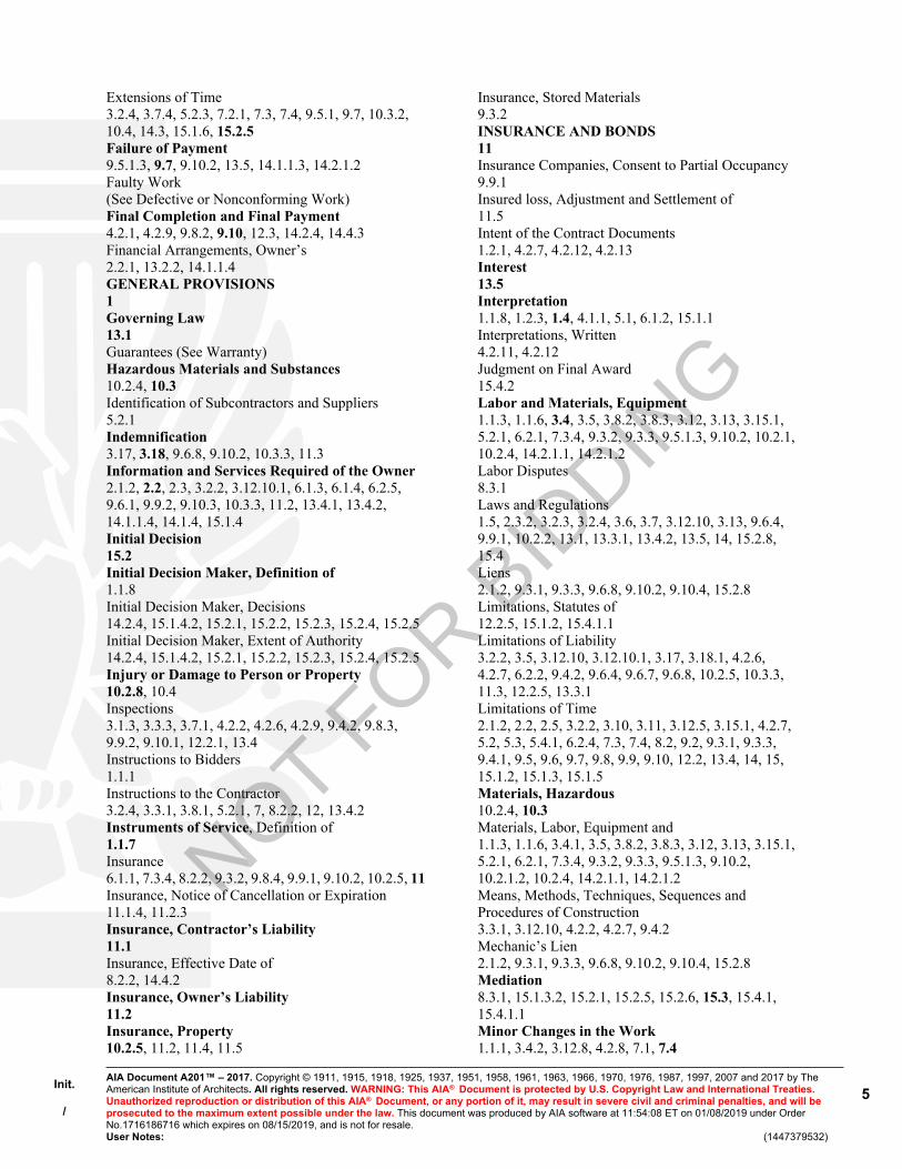
Init.
/
AIA Document A201™ – 2017. Copyright © 1911, 1915, 1918, 1925, 1937, 1951, 1958, 1961, 1963, 1966, 1970, 1976, 1987, 1997, 2007 and 2017 by The American Institute of Architects. All rights reserved. WARNING: This AIA® Document is protected by U.S. Copyright Law and International Treaties. Unauthorized reproduction or distribution of this AIA® Document, or any portion of it, may result in severe civil and criminal penalties, and will be prosecuted to the maximum extent possible under the law. This document was produced by AIA software at 11:54:08 ET on 01/08/2019 under Order No.1716186716 which expires on 08/15/2019, and is not for resale.User Notes: (1447379532)
5
Extensions of Time3.2.4, 3.7.4, 5.2.3, 7.2.1, 7.3, 7.4, 9.5.1, 9.7, 10.3.2, 10.4, 14.3, 15.1.6, 15.2.5Failure of Payment9.5.1.3, 9.7, 9.10.2, 13.5, 14.1.1.3, 14.2.1.2Faulty Work(See Defective or Nonconforming Work)Final Completion and Final Payment4.2.1, 4.2.9, 9.8.2, 9.10, 12.3, 14.2.4, 14.4.3Financial Arrangements, Owner’s2.2.1, 13.2.2, 14.1.1.4GENERAL PROVISIONS1Governing Law13.1Guarantees (See Warranty)Hazardous Materials and Substances10.2.4, 10.3Identification of Subcontractors and Suppliers5.2.1Indemnification3.17, 3.18, 9.6.8, 9.10.2, 10.3.3, 11.3Information and Services Required of the Owner2.1.2, 2.2, 2.3, 3.2.2, 3.12.10.1, 6.1.3, 6.1.4, 6.2.5, 9.6.1, 9.9.2, 9.10.3, 10.3.3, 11.2, 13.4.1, 13.4.2, 14.1.1.4, 14.1.4, 15.1.4Initial Decision15.2Initial Decision Maker, Definition of1.1.8Initial Decision Maker, Decisions14.2.4, 15.1.4.2, 15.2.1, 15.2.2, 15.2.3, 15.2.4, 15.2.5Initial Decision Maker, Extent of Authority14.2.4, 15.1.4.2, 15.2.1, 15.2.2, 15.2.3, 15.2.4, 15.2.5Injury or Damage to Person or Property10.2.8, 10.4Inspections3.1.3, 3.3.3, 3.7.1, 4.2.2, 4.2.6, 4.2.9, 9.4.2, 9.8.3, 9.9.2, 9.10.1, 12.2.1, 13.4Instructions to Bidders1.1.1Instructions to the Contractor3.2.4, 3.3.1, 3.8.1, 5.2.1, 7, 8.2.2, 12, 13.4.2Instruments of Service, Definition of1.1.7Insurance6.1.1, 7.3.4, 8.2.2, 9.3.2, 9.8.4, 9.9.1, 9.10.2, 10.2.5, 11Insurance, Notice of Cancellation or Expiration11.1.4, 11.2.3Insurance, Contractor’s Liability11.1Insurance, Effective Date of8.2.2, 14.4.2Insurance, Owner’s Liability11.2Insurance, Property10.2.5, 11.2, 11.4, 11.5
Insurance, Stored Materials9.3.2INSURANCE AND BONDS11Insurance Companies, Consent to Partial Occupancy9.9.1Insured loss, Adjustment and Settlement of11.5Intent of the Contract Documents1.2.1, 4.2.7, 4.2.12, 4.2.13Interest13.5Interpretation1.1.8, 1.2.3, 1.4, 4.1.1, 5.1, 6.1.2, 15.1.1Interpretations, Written4.2.11, 4.2.12Judgment on Final Award15.4.2Labor and Materials, Equipment1.1.3, 1.1.6, 3.4, 3.5, 3.8.2, 3.8.3, 3.12, 3.13, 3.15.1, 5.2.1, 6.2.1, 7.3.4, 9.3.2, 9.3.3, 9.5.1.3, 9.10.2, 10.2.1, 10.2.4, 14.2.1.1, 14.2.1.2Labor Disputes8.3.1Laws and Regulations1.5, 2.3.2, 3.2.3, 3.2.4, 3.6, 3.7, 3.12.10, 3.13, 9.6.4, 9.9.1, 10.2.2, 13.1, 13.3.1, 13.4.2, 13.5, 14, 15.2.8, 15.4Liens2.1.2, 9.3.1, 9.3.3, 9.6.8, 9.10.2, 9.10.4, 15.2.8Limitations, Statutes of12.2.5, 15.1.2, 15.4.1.1Limitations of Liability3.2.2, 3.5, 3.12.10, 3.12.10.1, 3.17, 3.18.1, 4.2.6, 4.2.7, 6.2.2, 9.4.2, 9.6.4, 9.6.7, 9.6.8, 10.2.5, 10.3.3, 11.3, 12.2.5, 13.3.1Limitations of Time2.1.2, 2.2, 2.5, 3.2.2, 3.10, 3.11, 3.12.5, 3.15.1, 4.2.7, 5.2, 5.3, 5.4.1, 6.2.4, 7.3, 7.4, 8.2, 9.2, 9.3.1, 9.3.3, 9.4.1, 9.5, 9.6, 9.7, 9.8, 9.9, 9.10, 12.2, 13.4, 14, 15, 15.1.2, 15.1.3, 15.1.5Materials, Hazardous10.2.4, 10.3Materials, Labor, Equipment and1.1.3, 1.1.6, 3.4.1, 3.5, 3.8.2, 3.8.3, 3.12, 3.13, 3.15.1, 5.2.1, 6.2.1, 7.3.4, 9.3.2, 9.3.3, 9.5.1.3, 9.10.2, 10.2.1.2, 10.2.4, 14.2.1.1, 14.2.1.2Means, Methods, Techniques, Sequences and Procedures of Construction3.3.1, 3.12.10, 4.2.2, 4.2.7, 9.4.2Mechanic’s Lien2.1.2, 9.3.1, 9.3.3, 9.6.8, 9.10.2, 9.10.4, 15.2.8Mediation8.3.1, 15.1.3.2, 15.2.1, 15.2.5, 15.2.6, 15.3, 15.4.1, 15.4.1.1Minor Changes in the Work1.1.1, 3.4.2, 3.12.8, 4.2.8, 7.1, 7.4
NOT FOR B
IDDIN
G

Init.
/
AIA Document A201™ – 2017. Copyright © 1911, 1915, 1918, 1925, 1937, 1951, 1958, 1961, 1963, 1966, 1970, 1976, 1987, 1997, 2007 and 2017 by The American Institute of Architects. All rights reserved. WARNING: This AIA® Document is protected by U.S. Copyright Law and International Treaties. Unauthorized reproduction or distribution of this AIA® Document, or any portion of it, may result in severe civil and criminal penalties, and will be prosecuted to the maximum extent possible under the law. This document was produced by AIA software at 11:54:08 ET on 01/08/2019 under Order No.1716186716 which expires on 08/15/2019, and is not for resale.User Notes: (1447379532)
6
MISCELLANEOUS PROVISIONS13Modifications, Definition of1.1.1Modifications to the Contract1.1.1, 1.1.2, 2.5, 3.11, 4.1.2, 4.2.1, 5.2.3, 7, 8.3.1, 9.7, 10.3.2Mutual Responsibility6.2Nonconforming Work, Acceptance of9.6.6, 9.9.3, 12.3Nonconforming Work, Rejection and Correction of2.4, 2.5, 3.5, 4.2.6, 6.2.4, 9.5.1, 9.8.2, 9.9.3, 9.10.4, 12.2Notice1.6, 1.6.1, 1.6.2, 2.1.2, 2.2.2., 2.2.3, 2.2.4, 2.5, 3.2.4, 3.3.1, 3.7.4, 3.7.5, 3.9.2, 3.12.9, 3.12.10, 5.2.1, 7.4, 8.2.2 9.6.8, 9.7, 9.10.1, 10.2.8, 10.3.2, 11.5, 12.2.2.1, 13.4.1, 13.4.2, 14.1, 14.2.2, 14.4.2, 15.1.3, 15.1.5, 15.1.6, 15.4.1Notice of Cancellation or Expiration of Insurance11.1.4, 11.2.3Notice of Claims1.6.2, 2.1.2, 3.7.4, 9.6.8, 10.2.8, 15.1.3, 15.1.5, 15.1.6, 15.2.8, 15.3.2, 15.4.1Notice of Testing and Inspections13.4.1, 13.4.2Observations, Contractor’s3.2, 3.7.4Occupancy2.3.1, 9.6.6, 9.8Orders, Written1.1.1, 2.4, 3.9.2, 7, 8.2.2, 11.5, 12.1, 12.2.2.1, 13.4.2, 14.3.1OWNER2Owner, Definition of2.1.1Owner, Evidence of Financial Arrangements2.2, 13.2.2, 14.1.1.4Owner, Information and Services Required of the2.1.2, 2.2, 2.3, 3.2.2, 3.12.10, 6.1.3, 6.1.4, 6.2.5, 9.3.2, 9.6.1, 9.6.4, 9.9.2, 9.10.3, 10.3.3, 11.2, 13.4.1, 13.4.2, 14.1.1.4, 14.1.4, 15.1.4Owner’s Authority1.5, 2.1.1, 2.3.32.4, 2.5, 3.4.2, 3.8.1, 3.12.10, 3.14.2, 4.1.2, 4.2.4, 4.2.9, 5.2.1, 5.2.4, 5.4.1, 6.1, 6.3, 7.2.1, 7.3.1, 8.2.2, 8.3.1, 9.3.2, 9.5.1, 9.6.4, 9.9.1, 9.10.2, 10.3.2, 11.4, 11.5, 12.2.2, 12.3, 13.2.2, 14.3, 14.4, 15.2.7Owner’s Insurance11.2Owner’s Relationship with Subcontractors1.1.2, 5.2, 5.3, 5.4, 9.6.4, 9.10.2, 14.2.2Owner’s Right to Carry Out the Work2.5, 14.2.2
Owner’s Right to Clean Up6.3Owner’s Right to Perform Construction and to Award Separate Contracts6.1Owner’s Right to Stop the Work2.4Owner’s Right to Suspend the Work14.3Owner’s Right to Terminate the Contract14.2, 14.4Ownership and Use of Drawings, Specifications and Other Instruments of Service1.1.1, 1.1.6, 1.1.7, 1.5, 2.3.6, 3.2.2, 3.11, 3.17, 4.2.12, 5.3Partial Occupancy or Use9.6.6, 9.9Patching, Cutting and3.14, 6.2.5Patents3.17Payment, Applications for4.2.5, 7.3.9, 9.2, 9.3, 9.4, 9.5, 9.6.3, 9.7, 9.8.5, 9.10.1, 14.2.3, 14.2.4, 14.4.3Payment, Certificates for4.2.5, 4.2.9, 9.3.3, 9.4, 9.5, 9.6.1, 9.6.6, 9.7, 9.10.1, 9.10.3, 14.1.1.3, 14.2.4Payment, Failure of9.5.1.3, 9.7, 9.10.2, 13.5, 14.1.1.3, 14.2.1.2Payment, Final4.2.1, 4.2.9, 9.10, 12.3, 14.2.4, 14.4.3Payment Bond, Performance Bond and7.3.4.4, 9.6.7, 9.10.3, 11.1.2Payments, Progress9.3, 9.6, 9.8.5, 9.10.3, 14.2.3, 15.1.4PAYMENTS AND COMPLETION9Payments to Subcontractors5.4.2, 9.5.1.3, 9.6.2, 9.6.3, 9.6.4, 9.6.7, 14.2.1.2PCB10.3.1Performance Bond and Payment Bond7.3.4.4, 9.6.7, 9.10.3, 11.1.2Permits, Fees, Notices and Compliance with Laws2.3.1, 3.7, 3.13, 7.3.4.4, 10.2.2PERSONS AND PROPERTY, PROTECTION OF10Polychlorinated Biphenyl10.3.1Product Data, Definition of3.12.2Product Data and Samples, Shop Drawings3.11, 3.12, 4.2.7Progress and Completion4.2.2, 8.2, 9.8, 9.9.1, 14.1.4, 15.1.4Progress Payments9.3, 9.6, 9.8.5, 9.10.3, 14.2.3, 15.1.4
NOT FOR B
IDDIN
G
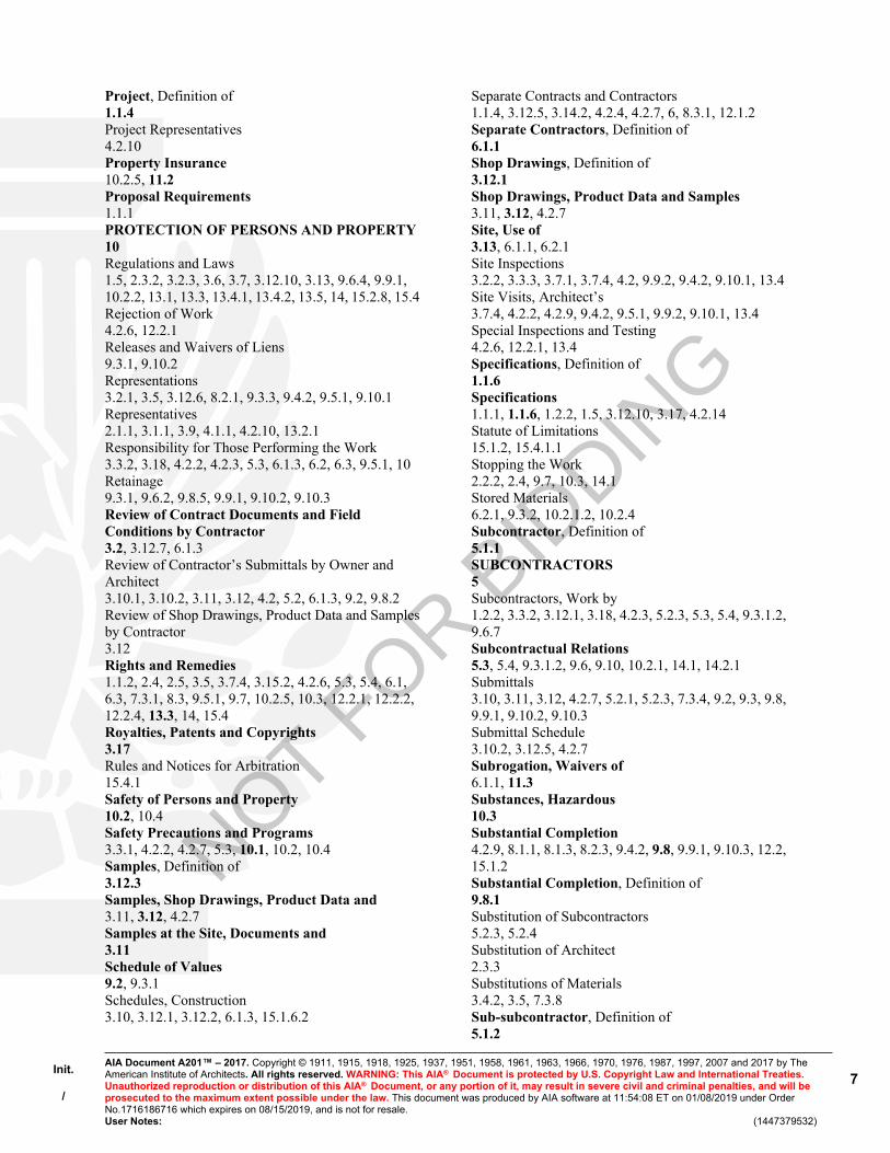
Init.
/
AIA Document A201™ – 2017. Copyright © 1911, 1915, 1918, 1925, 1937, 1951, 1958, 1961, 1963, 1966, 1970, 1976, 1987, 1997, 2007 and 2017 by The American Institute of Architects. All rights reserved. WARNING: This AIA® Document is protected by U.S. Copyright Law and International Treaties. Unauthorized reproduction or distribution of this AIA® Document, or any portion of it, may result in severe civil and criminal penalties, and will be prosecuted to the maximum extent possible under the law. This document was produced by AIA software at 11:54:08 ET on 01/08/2019 under Order No.1716186716 which expires on 08/15/2019, and is not for resale.User Notes: (1447379532)
7
Project, Definition of1.1.4Project Representatives4.2.10Property Insurance10.2.5, 11.2Proposal Requirements1.1.1PROTECTION OF PERSONS AND PROPERTY10Regulations and Laws1.5, 2.3.2, 3.2.3, 3.6, 3.7, 3.12.10, 3.13, 9.6.4, 9.9.1, 10.2.2, 13.1, 13.3, 13.4.1, 13.4.2, 13.5, 14, 15.2.8, 15.4Rejection of Work4.2.6, 12.2.1Releases and Waivers of Liens9.3.1, 9.10.2Representations3.2.1, 3.5, 3.12.6, 8.2.1, 9.3.3, 9.4.2, 9.5.1, 9.10.1Representatives2.1.1, 3.1.1, 3.9, 4.1.1, 4.2.10, 13.2.1Responsibility for Those Performing the Work3.3.2, 3.18, 4.2.2, 4.2.3, 5.3, 6.1.3, 6.2, 6.3, 9.5.1, 10Retainage9.3.1, 9.6.2, 9.8.5, 9.9.1, 9.10.2, 9.10.3Review of Contract Documents and Field Conditions by Contractor3.2, 3.12.7, 6.1.3Review of Contractor’s Submittals by Owner and Architect3.10.1, 3.10.2, 3.11, 3.12, 4.2, 5.2, 6.1.3, 9.2, 9.8.2Review of Shop Drawings, Product Data and Samples by Contractor3.12Rights and Remedies1.1.2, 2.4, 2.5, 3.5, 3.7.4, 3.15.2, 4.2.6, 5.3, 5.4, 6.1, 6.3, 7.3.1, 8.3, 9.5.1, 9.7, 10.2.5, 10.3, 12.2.1, 12.2.2, 12.2.4, 13.3, 14, 15.4Royalties, Patents and Copyrights3.17Rules and Notices for Arbitration15.4.1Safety of Persons and Property10.2, 10.4Safety Precautions and Programs3.3.1, 4.2.2, 4.2.7, 5.3, 10.1, 10.2, 10.4Samples, Definition of3.12.3Samples, Shop Drawings, Product Data and3.11, 3.12, 4.2.7Samples at the Site, Documents and3.11Schedule of Values9.2, 9.3.1Schedules, Construction3.10, 3.12.1, 3.12.2, 6.1.3, 15.1.6.2
Separate Contracts and Contractors1.1.4, 3.12.5, 3.14.2, 4.2.4, 4.2.7, 6, 8.3.1, 12.1.2Separate Contractors, Definition of6.1.1Shop Drawings, Definition of3.12.1Shop Drawings, Product Data and Samples3.11, 3.12, 4.2.7Site, Use of3.13, 6.1.1, 6.2.1Site Inspections3.2.2, 3.3.3, 3.7.1, 3.7.4, 4.2, 9.9.2, 9.4.2, 9.10.1, 13.4Site Visits, Architect’s3.7.4, 4.2.2, 4.2.9, 9.4.2, 9.5.1, 9.9.2, 9.10.1, 13.4Special Inspections and Testing4.2.6, 12.2.1, 13.4Specifications, Definition of1.1.6Specifications1.1.1, 1.1.6, 1.2.2, 1.5, 3.12.10, 3.17, 4.2.14Statute of Limitations15.1.2, 15.4.1.1Stopping the Work2.2.2, 2.4, 9.7, 10.3, 14.1Stored Materials6.2.1, 9.3.2, 10.2.1.2, 10.2.4Subcontractor, Definition of5.1.1SUBCONTRACTORS5Subcontractors, Work by1.2.2, 3.3.2, 3.12.1, 3.18, 4.2.3, 5.2.3, 5.3, 5.4, 9.3.1.2, 9.6.7Subcontractual Relations5.3, 5.4, 9.3.1.2, 9.6, 9.10, 10.2.1, 14.1, 14.2.1Submittals3.10, 3.11, 3.12, 4.2.7, 5.2.1, 5.2.3, 7.3.4, 9.2, 9.3, 9.8, 9.9.1, 9.10.2, 9.10.3Submittal Schedule3.10.2, 3.12.5, 4.2.7Subrogation, Waivers of6.1.1, 11.3Substances, Hazardous10.3Substantial Completion4.2.9, 8.1.1, 8.1.3, 8.2.3, 9.4.2, 9.8, 9.9.1, 9.10.3, 12.2, 15.1.2Substantial Completion, Definition of9.8.1Substitution of Subcontractors5.2.3, 5.2.4Substitution of Architect2.3.3Substitutions of Materials3.4.2, 3.5, 7.3.8Sub-subcontractor, Definition of5.1.2
NOT FOR B
IDDIN
G
Init.
/
AIA Document A201™ – 2017. Copyright © 1911, 1915, 1918, 1925, 1937, 1951, 1958, 1961, 1963, 1966, 1970, 1976, 1987, 1997, 2007 and 2017 by The American Institute of Architects. All rights reserved. WARNING: This AIA® Document is protected by U.S. Copyright Law and International Treaties. Unauthorized reproduction or distribution of this AIA® Document, or any portion of it, may result in severe civil and criminal penalties, and will be prosecuted to the maximum extent possible under the law. This document was produced by AIA software at 11:54:08 ET on 01/08/2019 under Order No.1716186716 which expires on 08/15/2019, and is not for resale.User Notes: (1447379532)
8
Subsurface Conditions3.7.4Successors and Assigns13.2Superintendent3.9, 10.2.6Supervision and Construction Procedures1.2.2, 3.3, 3.4, 3.12.10, 4.2.2, 4.2.7, 6.1.3, 6.2.4, 7.1.3, 7.3.4, 8.2, 8.3.1, 9.4.2, 10, 12, 14, 15.1.4Suppliers1.5, 3.12.1, 4.2.4, 4.2.6, 5.2.1, 9.3, 9.4.2, 9.5.4, 9.6, 9.10.5, 14.2.1Surety5.4.1.2, 9.6.8, 9.8.5, 9.10.2, 9.10.3, 11.1.2, 14.2.2, 15.2.7Surety, Consent of9.8.5, 9.10.2, 9.10.3Surveys1.1.7, 2.3.4Suspension by the Owner for Convenience14.3Suspension of the Work3.7.5, 5.4.2, 14.3Suspension or Termination of the Contract5.4.1.1, 14Taxes3.6, 3.8.2.1, 7.3.4.4Termination by the Contractor14.1, 15.1.7Termination by the Owner for Cause5.4.1.1, 14.2, 15.1.7Termination by the Owner for Convenience14.4Termination of the Architect2.3.3Termination of the Contractor Employment14.2.2
TERMINATION OR SUSPENSION OF THE CONTRACT14Tests and Inspections3.1.3, 3.3.3, 3.7.1, 4.2.2, 4.2.6, 4.2.9, 9.4.2, 9.8.3, 9.9.2, 9.10.1, 10.3.2, 12.2.1, 13.4TIME8Time, Delays and Extensions of3.2.4, 3.7.4, 5.2.3, 7.2.1, 7.3.1, 7.4, 8.3, 9.5.1, 9.7, 10.3.2, 10.4, 14.3.2, 15.1.6, 15.2.5
Time Limits2.1.2, 2.2, 2.5, 3.2.2, 3.10, 3.11, 3.12.5, 3.15.1, 4.2, 5.2, 5.3, 5.4, 6.2.4, 7.3, 7.4, 8.2, 9.2, 9.3.1, 9.3.3, 9.4.1, 9.5, 9.6, 9.7, 9.8, 9.9, 9.10, 12.2, 13.4, 14, 15.1.2, 15.1.3, 15.4Time Limits on Claims3.7.4, 10.2.8, 15.1.2, 15.1.3Title to Work9.3.2, 9.3.3UNCOVERING AND CORRECTION OF WORK12Uncovering of Work12.1Unforeseen Conditions, Concealed or Unknown3.7.4, 8.3.1, 10.3Unit Prices7.3.3.2, 9.1.2Use of Documents1.1.1, 1.5, 2.3.6, 3.12.6, 5.3Use of Site3.13, 6.1.1, 6.2.1Values, Schedule of9.2, 9.3.1Waiver of Claims by the Architect13.3.2Waiver of Claims by the Contractor9.10.5, 13.3.2, 15.1.7Waiver of Claims by the Owner9.9.3, 9.10.3, 9.10.4, 12.2.2.1, 13.3.2, 14.2.4, 15.1.7Waiver of Consequential Damages14.2.4, 15.1.7Waiver of Liens9.3, 9.10.2, 9.10.4Waivers of Subrogation6.1.1, 11.3Warranty3.5, 4.2.9, 9.3.3, 9.8.4, 9.9.1, 9.10.2, 9.10.4, 12.2.2, 15.1.2Weather Delays8.3, 15.1.6.2Work, Definition of1.1.3Written Consent1.5.2, 3.4.2, 3.7.4, 3.12.8, 3.14.2, 4.1.2, 9.3.2, 9.10.3, 13.2, 13.3.2, 15.4.4.2Written Interpretations4.2.11, 4.2.12Written Orders1.1.1, 2.4, 3.9, 7, 8.2.2, 12.1, 12.2, 13.4.2, 14.3.1
NOT FOR B
IDDIN
G

Init.
/
AIA Document A201™ – 2017. Copyright © 1911, 1915, 1918, 1925, 1937, 1951, 1958, 1961, 1963, 1966, 1970, 1976, 1987, 1997, 2007 and 2017 by The American Institute of Architects. All rights reserved. WARNING: This AIA® Document is protected by U.S. Copyright Law and International Treaties. Unauthorized reproduction or distribution of this AIA® Document, or any portion of it, may result in severe civil and criminal penalties, and will be prosecuted to the maximum extent possible under the law. This document was produced by AIA software at 11:54:08 ET on 01/08/2019 under Order No.1716186716 which expires on 08/15/2019, and is not for resale.User Notes: (1447379532)
9
ARTICLE 1 GENERAL PROVISIONS§ 1.1 Basic Definitions§ 1.1.1 The Contract DocumentsThe Contract Documents are enumerated in the Agreement between the Owner and Contractor (hereinafter the Agreement) and consist of the Agreement, Conditions of the Contract (General, Supplementary and other Conditions), Drawings, Specifications, Addenda issued prior to execution of the Contract, other documents listed in the Agreement, and Modifications issued after execution of the Contract. A Modification is (1) a written amendment to the Contract signed by both parties, (2) a Change Order, (3) a Construction Change Directive, or (4) a written order for a minor change in the Work issued by the Architect. Unless specifically enumerated in the Agreement, the Contract Documents do not include the advertisement or invitation to bid, Instructions to Bidders, sample forms, other information furnished by the Owner in anticipation of receiving bids or proposals, the Contractor’s bid or proposal, or portions of Addenda relating to bidding or proposal requirements.
§ 1.1.2 The ContractThe Contract Documents form the Contract for Construction. The Contract represents the entire and integrated agreement between the parties hereto and supersedes prior negotiations, representations, or agreements, either written or oral. The Contract may be amended or modified only by a Modification. The Contract Documents shall not be construed to create a contractual relationship of any kind (1) between the Contractor and the Architect or the Architect’s consultants, (2) between the Owner and a Subcontractor or a Sub-subcontractor, (3) between the Owner and the Architect or the Architect’s consultants, or (4) between any persons or entities other than the Owner and the Contractor. The Architect shall, however, be entitled to performance and enforcement of obligations under the Contract intended to facilitate performance of the Architect’s duties.
§ 1.1.3 The WorkThe term "Work" means the construction and services required by the Contract Documents, whether completed or partially completed, and includes all other labor, materials, equipment, and services provided or to be provided by the Contractor to fulfill the Contractor’s obligations. The Work may constitute the whole or a part of the Project.
§ 1.1.4 The ProjectThe Project is the total construction of which the Work performed under the Contract Documents may be the whole or a part and which may include construction by the Owner and by Separate Contractors.
§ 1.1.5 The DrawingsThe Drawings are the graphic and pictorial portions of the Contract Documents showing the design, location and dimensions of the Work, generally including plans, elevations, sections, details, schedules, and diagrams.
§ 1.1.6 The SpecificationsThe Specifications are that portion of the Contract Documents consisting of the written requirements for materials, equipment, systems, standards and workmanship for the Work, and performance of related services.
§ 1.1.7 Instruments of ServiceInstruments of Service are representations, in any medium of expression now known or later developed, of the tangible and intangible creative work performed by the Architect and the Architect’s consultants under their respective professional services agreements. Instruments of Service may include, without limitation, studies, surveys, models, sketches, drawings, specifications, and other similar materials.
§ 1.1.8 Initial Decision MakerThe Initial Decision Maker is the person identified in the Agreement to render initial decisions on Claims in accordance with Section 15.2. The Initial Decision Maker shall not show partiality to the Owner or Contractor and shall not be liable for results of interpretations or decisions rendered in good faith.
§ 1.2 Correlation and Intent of the Contract Documents§ 1.2.1 The intent of the Contract Documents is to include all items necessary for the proper execution and completion of the Work by the Contractor. The Contract Documents are complementary, and what is required by one shall be as binding as if required by all; performance by the Contractor shall be required only to the extent consistent with the Contract Documents and reasonably inferable from them as being necessary to produce the indicated results.
NOT FOR B
IDDIN
G

Init.
/
AIA Document A201™ – 2017. Copyright © 1911, 1915, 1918, 1925, 1937, 1951, 1958, 1961, 1963, 1966, 1970, 1976, 1987, 1997, 2007 and 2017 by The American Institute of Architects. All rights reserved. WARNING: This AIA® Document is protected by U.S. Copyright Law and International Treaties. Unauthorized reproduction or distribution of this AIA® Document, or any portion of it, may result in severe civil and criminal penalties, and will be prosecuted to the maximum extent possible under the law. This document was produced by AIA software at 11:54:08 ET on 01/08/2019 under Order No.1716186716 which expires on 08/15/2019, and is not for resale.User Notes: (1447379532)
10
§ 1.2.1.1 The invalidity of any provision of the Contract Documents shall not invalidate the Contract or its remaining provisions. If it is determined that any provision of the Contract Documents violates any law, or is otherwise invalid or unenforceable, then that provision shall be revised to the extent necessary to make that provision legal and enforceable. In such case the Contract Documents shall be construed, to the fullest extent permitted by law, to give effect to the parties’ intentions and purposes in executing the Contract.
§ 1.2.2 Organization of the Specifications into divisions, sections and articles, and arrangement of Drawings shall not control the Contractor in dividing the Work among Subcontractors or in establishing the extent of Work to be performed by any trade.
§ 1.2.3 Unless otherwise stated in the Contract Documents, words that have well-known technical or construction industry meanings are used in the Contract Documents in accordance with such recognized meanings.
§ 1.3 CapitalizationTerms capitalized in these General Conditions include those that are (1) specifically defined, (2) the titles of numbered articles, or (3) the titles of other documents published by the American Institute of Architects.
§ 1.4 InterpretationIn the interest of brevity the Contract Documents frequently omit modifying words such as "all" and "any" and articles such as "the" and "an," but the fact that a modifier or an article is absent from one statement and appears in another is not intended to affect the interpretation of either statement.
§ 1.5 Ownership and Use of Drawings, Specifications, and Other Instruments of Service§ 1.5.1 The Architect and the Architect’s consultants shall be deemed the authors and owners of their respective Instruments of Service, including the Drawings and Specifications, and retain all common law, statutory, and other reserved rights in their Instruments of Service, including copyrights. The Contractor, Subcontractors, Sub-subcontractors, and suppliers shall not own or claim a copyright in the Instruments of Service. Submittal or distribution to meet official regulatory requirements or for other purposes in connection with the Project is not to be construed as publication in derogation of the Architect’s or Architect’s consultants’ reserved rights.
§ 1.5.2 The Contractor, Subcontractors, Sub-subcontractors, and suppliers are authorized to use and reproduce the Instruments of Service provided to them, subject to any protocols established pursuant to Sections 1.7 and 1.8, solely and exclusively for execution of the Work. All copies made under this authorization shall bear the copyright notice, if any, shown on the Instruments of Service. The Contractor, Subcontractors, Sub-subcontractors, and suppliers may not use the Instruments of Service on other projects or for additions to the Project outside the scope of the Work without the specific written consent of the Owner, Architect, and the Architect’s consultants.
§ 1.6 Notice§ 1.6.1 Except as otherwise provided in Section 1.6.2, where the Contract Documents require one party to notify or give notice to the other party, such notice shall be provided in writing to the designated representative of the party to whom the notice is addressed and shall be deemed to have been duly served if delivered in person, by mail, by courier, or by electronic transmission if a method for electronic transmission is set forth in the Agreement.
§ 1.6.2 Notice of Claims as provided in Section 15.1.3 shall be provided in writing and shall be deemed to have been duly served only if delivered to the designated representative of the party to whom the notice is addressed by certified or registered mail, or by courier providing proof of delivery.
§ 1.7 Digital Data Use and TransmissionThe parties shall agree upon protocols governing the transmission and use of Instruments of Service or any other information or documentation in digital form. The parties will use AIA Document E203™–2013, Building Information Modeling and Digital Data Exhibit, to establish the protocols for the development, use, transmission, and exchange of digital data.
§ 1.8 Building Information Models Use and RelianceAny use of, or reliance on, all or a portion of a building information model without agreement to protocols governing the use of, and reliance on, the information contained in the model and without having those protocols set forth in AIA Document E203™–2013, Building Information Modeling and Digital Data Exhibit, and the requisite AIA Document
NOT FOR B
IDDIN
G

Init.
/
AIA Document A201™ – 2017. Copyright © 1911, 1915, 1918, 1925, 1937, 1951, 1958, 1961, 1963, 1966, 1970, 1976, 1987, 1997, 2007 and 2017 by The American Institute of Architects. All rights reserved. WARNING: This AIA® Document is protected by U.S. Copyright Law and International Treaties. Unauthorized reproduction or distribution of this AIA® Document, or any portion of it, may result in severe civil and criminal penalties, and will be prosecuted to the maximum extent possible under the law. This document was produced by AIA software at 11:54:08 ET on 01/08/2019 under Order No.1716186716 which expires on 08/15/2019, and is not for resale.User Notes: (1447379532)
11
G202™–2013, Project Building Information Modeling Protocol Form, shall be at the using or relying party’s sole risk and without liability to the other party and its contractors or consultants, the authors of, or contributors to, the building information model, and each of their agents and employees.
ARTICLE 2 OWNER§ 2.1 General§ 2.1.1 The Owner is the person or entity identified as such in the Agreement and is referred to throughout the Contract Documents as if singular in number. The Owner shall designate in writing a representative who shall have express authority to bind the Owner with respect to all matters requiring the Owner’s approval or authorization. Except as otherwise provided in Section 4.2.1, the Architect does not have such authority. The term "Owner" means the Owner or the Owner’s authorized representative.
§ 2.1.2 The Owner shall furnish to the Contractor, within fifteen days after receipt of a written request, information necessary and relevant for the Contractor to evaluate, give notice of, or enforce mechanic’s lien rights. Such information shall include a correct statement of the record legal title to the property on which the Project is located, usually referred to as the site, and the Owner’s interest therein.
§ 2.2 Evidence of the Owner’s Financial Arrangements§ 2.2.1 Prior to commencement of the Work and upon written request by the Contractor, the Owner shall furnish to the Contractor reasonable evidence that the Owner has made financial arrangements to fulfill the Owner’s obligations under the Contract. The Contractor shall have no obligation to commence the Work until the Owner provides such evidence. If commencement of the Work is delayed under this Section 2.2.1, the Contract Time shall be extended appropriately.
§ 2.2.2 Following commencement of the Work and upon written request by the Contractor, the Owner shall furnish to the Contractor reasonable evidence that the Owner has made financial arrangements to fulfill the Owner’s obligations under the Contract only if (1) the Owner fails to make payments to the Contractor as the Contract Documents require; (2) the Contractor identifies in writing a reasonable concern regarding the Owner’s ability to make payment when due; or (3) a change in the Work materially changes the Contract Sum. If the Owner fails to provide such evidence, as required, within fourteen days of the Contractor’s request, the Contractor may immediately stop the Work and, in that event, shall notify the Owner that the Work has stopped. However, if the request is made because a change in the Work materially changes the Contract Sum under (3) above, the Contractor may immediately stop only that portion of the Work affected by the change until reasonable evidence is provided. If the Work is stopped under this Section 2.2.2, the Contract Time shall be extended appropriately and the Contract Sum shall be increased by the amount of the Contractor’s reasonable costs of shutdown, delay and start-up, plus interest as provided in the Contract Documents.
§ 2.2.3 After the Owner furnishes evidence of financial arrangements under this Section 2.2, the Owner shall not materially vary such financial arrangements without prior notice to the Contractor.
§ 2.2.4 Where the Owner has designated information furnished under this Section 2.2 as "confidential," the Contractor shall keep the information confidential and shall not disclose it to any other person. However, the Contractor may disclose "confidential" information, after seven (7) days’ notice to the Owner, where disclosure is required by law, including a subpoena or other form of compulsory legal process issued by a court or governmental entity, or by court or arbitrator(s) order. The Contractor may also disclose "confidential" information to its employees, consultants, sureties, Subcontractors and their employees, Sub-subcontractors, and others who need to know the content of such information solely and exclusively for the Project and who agree to maintain the confidentiality of such information.
§ 2.3 Information and Services Required of the Owner§ 2.3.1 Except for permits and fees that are the responsibility of the Contractor under the Contract Documents, including those required under Section 3.7.1, the Owner shall secure and pay for necessary approvals, easements, assessments and charges required for construction, use or occupancy of permanent structures or for permanent changes in existing facilities.
§ 2.3.2 The Owner shall retain an architect lawfully licensed to practice architecture, or an entity lawfully practicing architecture, in the jurisdiction where the Project is located. That person or entity is identified as the Architect in the Agreement and is referred to throughout the Contract Documents as if singular in number.
NOT FOR B
IDDIN
G

Init.
/
AIA Document A201™ – 2017. Copyright © 1911, 1915, 1918, 1925, 1937, 1951, 1958, 1961, 1963, 1966, 1970, 1976, 1987, 1997, 2007 and 2017 by The American Institute of Architects. All rights reserved. WARNING: This AIA® Document is protected by U.S. Copyright Law and International Treaties. Unauthorized reproduction or distribution of this AIA® Document, or any portion of it, may result in severe civil and criminal penalties, and will be prosecuted to the maximum extent possible under the law. This document was produced by AIA software at 11:54:08 ET on 01/08/2019 under Order No.1716186716 which expires on 08/15/2019, and is not for resale.User Notes: (1447379532)
12
§ 2.3.3 If the employment of the Architect terminates, the Owner shall employ a successor to whom the Contractor has no reasonable objection and whose status under the Contract Documents shall be that of the Architect.
§ 2.3.4 The Owner shall furnish surveys describing physical characteristics, legal limitations and utility locations for the site of the Project, and a legal description of the site. The Contractor shall be entitled to rely on the accuracy of information furnished by the Owner but shall exercise proper precautions relating to the safe performance of the Work.
§ 2.3.5 The Owner shall furnish information or services required of the Owner by the Contract Documents with reasonable promptness. The Owner shall also furnish any other information or services under the Owner’s control and relevant to the Contractor’s performance of the Work with reasonable promptness after receiving the Contractor’s written request for such information or services.
§ 2.3.6 Unless otherwise provided in the Contract Documents, the Owner shall furnish to the Contractor one copy of the Contract Documents for purposes of making reproductions pursuant to Section 1.5.2.
§ 2.4 Owner’s Right to Stop the WorkIf the Contractor fails to correct Work that is not in accordance with the requirements of the Contract Documents as required by Section 12.2 or repeatedly fails to carry out Work in accordance with the Contract Documents, the Owner may issue a written order to the Contractor to stop the Work, or any portion thereof, until the cause for such order has been eliminated; however, the right of the Owner to stop the Work shall not give rise to a duty on the part of the Owner to exercise this right for the benefit of the Contractor or any other person or entity, except to the extent required by Section 6.1.3.
§ 2.5 Owner’s Right to Carry Out the WorkIf the Contractor defaults or neglects to carry out the Work in accordance with the Contract Documents and fails within a ten-day period after receipt of notice from the Owner to commence and continue correction of such default or neglect with diligence and promptness, the Owner may, without prejudice to other remedies the Owner may have, correct such default or neglect. Such action by the Owner and amounts charged to the Contractor are both subject to prior approval of the Architect and the Architect may, pursuant to Section 9.5.1, withhold or nullify a Certificate for Payment in whole or in part, to the extent reasonably necessary to reimburse the Owner for the reasonable cost of correcting such deficiencies, including Owner’s expenses and compensation for the Architect’s additional services made necessary by such default, neglect, or failure. If current and future payments are not sufficient to cover such amounts, the Contractor shall pay the difference to the Owner. If the Contractor disagrees with the actions of the Owner or the Architect, or the amounts claimed as costs to the Owner, the Contractor may file a Claim pursuant to Article 15.
ARTICLE 3 CONTRACTOR§ 3.1 General§ 3.1.1 The Contractor is the person or entity identified as such in the Agreement and is referred to throughout the Contract Documents as if singular in number. The Contractor shall be lawfully licensed, if required in the jurisdiction where the Project is located. The Contractor shall designate in writing a representative who shall have express authority to bind the Contractor with respect to all matters under this Contract. The term "Contractor" means the Contractor or the Contractor’s authorized representative.
§ 3.1.2 The Contractor shall perform the Work in accordance with the Contract Documents.
§ 3.1.3 The Contractor shall not be relieved of its obligations to perform the Work in accordance with the Contract Documents either by activities or duties of the Architect in the Architect’s administration of the Contract, or by tests, inspections or approvals required or performed by persons or entities other than the Contractor.
§ 3.2 Review of Contract Documents and Field Conditions by Contractor§ 3.2.1 Execution of the Contract by the Contractor is a representation that the Contractor has visited the site, become generally familiar with local conditions under which the Work is to be performed, and correlated personal observations with requirements of the Contract Documents.
NOT FOR B
IDDIN
G
Init.
/
AIA Document A201™ – 2017. Copyright © 1911, 1915, 1918, 1925, 1937, 1951, 1958, 1961, 1963, 1966, 1970, 1976, 1987, 1997, 2007 and 2017 by The American Institute of Architects. All rights reserved. WARNING: This AIA® Document is protected by U.S. Copyright Law and International Treaties. Unauthorized reproduction or distribution of this AIA® Document, or any portion of it, may result in severe civil and criminal penalties, and will be prosecuted to the maximum extent possible under the law. This document was produced by AIA software at 11:54:08 ET on 01/08/2019 under Order No.1716186716 which expires on 08/15/2019, and is not for resale.User Notes: (1447379532)
13
§ 3.2.2 Because the Contract Documents are complementary, the Contractor shall, before starting each portion of the Work, carefully study and compare the various Contract Documents relative to that portion of the Work, as well as the information furnished by the Owner pursuant to Section 2.3.4, shall take field measurements of any existing conditions related to that portion of the Work, and shall observe any conditions at the site affecting it. These obligations are for the purpose of facilitating coordination and construction by the Contractor and are not for the purpose of discovering errors, omissions, or inconsistencies in the Contract Documents; however, the Contractor shall promptly report to the Architect any errors, inconsistencies or omissions discovered by or made known to the Contractor as a request for information in such form as the Architect may require. It is recognized that the Contractor’s review is made in the Contractor’s capacity as a contractor and not as a licensed design professional, unless otherwise specifically provided in the Contract Documents.
§ 3.2.3 The Contractor is not required to ascertain that the Contract Documents are in accordance with applicable laws, statutes, ordinances, codes, rules and regulations, or lawful orders of public authorities, but the Contractor shall promptly report to the Architect any nonconformity discovered by or made known to the Contractor as a request for information in such form as the Architect may require.
§ 3.2.4 If the Contractor believes that additional cost or time is involved because of clarifications or instructions the Architect issues in response to the Contractor’s notices or requests for information pursuant to Sections 3.2.2 or 3.2.3, the Contractor shall submit Claims as provided in Article 15. If the Contractor fails to perform the obligations of Sections 3.2.2 or 3.2.3, the Contractor shall pay such costs and damages to the Owner, subject to Section 15.1.7, as would have been avoided if the Contractor had performed such obligations. If the Contractor performs those obligations, the Contractor shall not be liable to the Owner or Architect for damages resulting from errors, inconsistencies or omissions in the Contract Documents, for differences between field measurements or conditions and the Contract Documents, or for nonconformities of the Contract Documents to applicable laws, statutes, ordinances, codes, rules and regulations, and lawful orders of public authorities.
§ 3.3 Supervision and Construction Procedures§ 3.3.1 The Contractor shall supervise and direct the Work, using the Contractor’s best skill and attention. The Contractor shall be solely responsible for, and have control over, construction means, methods, techniques, sequences, and procedures, and for coordinating all portions of the Work under the Contract. If the Contract Documents give specific instructions concerning construction means, methods, techniques, sequences, or procedures, the Contractor shall evaluate the jobsite safety thereof and shall be solely responsible for the jobsite safety of such means, methods, techniques, sequences, or procedures. If the Contractor determines that such means, methods, techniques, sequences or procedures may not be safe, the Contractor shall give timely notice to the Owner and Architect, and shall propose alternative means, methods, techniques, sequences, or procedures. The Architect shall evaluate the proposed alternative solely for conformance with the design intent for the completed construction. Unless the Architect objects to the Contractor’s proposed alternative, the Contractor shall perform the Work using its alternative means, methods, techniques, sequences, or procedures.
§ 3.3.2 The Contractor shall be responsible to the Owner for acts and omissions of the Contractor’s employees, Subcontractors and their agents and employees, and other persons or entities performing portions of the Work for, or on behalf of, the Contractor or any of its Subcontractors.
§ 3.3.3 The Contractor shall be responsible for inspection of portions of Work already performed to determine that such portions are in proper condition to receive subsequent Work.
§ 3.4 Labor and Materials§ 3.4.1 Unless otherwise provided in the Contract Documents, the Contractor shall provide and pay for labor, materials, equipment, tools, construction equipment and machinery, water, heat, utilities, transportation, and other facilities and services necessary for proper execution and completion of the Work, whether temporary or permanent and whether or not incorporated or to be incorporated in the Work.
§ 3.4.2 Except in the case of minor changes in the Work approved by the Architect in accordance with Section 3.12.8 or ordered by the Architect in accordance with Section 7.4, the Contractor may make substitutions only with the consent of the Owner, after evaluation by the Architect and in accordance with a Change Order or Construction Change Directive.
NOT FOR B
IDDIN
G
Init.
/
AIA Document A201™ – 2017. Copyright © 1911, 1915, 1918, 1925, 1937, 1951, 1958, 1961, 1963, 1966, 1970, 1976, 1987, 1997, 2007 and 2017 by The American Institute of Architects. All rights reserved. WARNING: This AIA® Document is protected by U.S. Copyright Law and International Treaties. Unauthorized reproduction or distribution of this AIA® Document, or any portion of it, may result in severe civil and criminal penalties, and will be prosecuted to the maximum extent possible under the law. This document was produced by AIA software at 11:54:08 ET on 01/08/2019 under Order No.1716186716 which expires on 08/15/2019, and is not for resale.User Notes: (1447379532)
14
§ 3.4.3 The Contractor shall enforce strict discipline and good order among the Contractor’s employees and other persons carrying out the Work. The Contractor shall not permit employment of unfit persons or persons not properly skilled in tasks assigned to them.
§ 3.5 Warranty§ 3.5.1 The Contractor warrants to the Owner and Architect that materials and equipment furnished under the Contract will be of good quality and new unless the Contract Documents require or permit otherwise. The Contractor further warrants that the Work will conform to the requirements of the Contract Documents and will be free from defects, except for those inherent in the quality of the Work the Contract Documents require or permit. Work, materials, or equipment not conforming to these requirements may be considered defective. The Contractor’s warranty excludes remedy for damage or defect caused by abuse, alterations to the Work not executed by the Contractor, improper or insufficient maintenance, improper operation, or normal wear and tear and normal usage. If required by the Architect, the Contractor shall furnish satisfactory evidence as to the kind and quality of materials and equipment.
§ 3.5.2 All material, equipment, or other special warranties required by the Contract Documents shall be issued in the name of the Owner, or shall be transferable to the Owner, and shall commence in accordance with Section 9.8.4.
§ 3.6 TaxesThe Contractor shall pay sales, consumer, use and similar taxes for the Work provided by the Contractor that are legally enacted when bids are received or negotiations concluded, whether or not yet effective or merely scheduled to go into effect.
§ 3.7 Permits, Fees, Notices and Compliance with Laws§ 3.7.1 Unless otherwise provided in the Contract Documents, the Contractor shall secure and pay for the building permit as well as for other permits, fees, licenses, and inspections by government agencies necessary for proper execution and completion of the Work that are customarily secured after execution of the Contract and legally required at the time bids are received or negotiations concluded.
§ 3.7.2 The Contractor shall comply with and give notices required by applicable laws, statutes, ordinances, codes, rules and regulations, and lawful orders of public authorities applicable to performance of the Work.
§ 3.7.3 If the Contractor performs Work knowing it to be contrary to applicable laws, statutes, ordinances, codes, rules and regulations, or lawful orders of public authorities, the Contractor shall assume appropriate responsibility for such Work and shall bear the costs attributable to correction.
§ 3.7.4 Concealed or Unknown ConditionsIf the Contractor encounters conditions at the site that are (1) subsurface or otherwise concealed physical conditions that differ materially from those indicated in the Contract Documents or (2) unknown physical conditions of an unusual nature that differ materially from those ordinarily found to exist and generally recognized as inherent in construction activities of the character provided for in the Contract Documents, the Contractor shall promptly provide notice to the Owner and the Architect before conditions are disturbed and in no event later than 14 days after first observance of the conditions. The Architect will promptly investigate such conditions and, if the Architect determines that they differ materially and cause an increase or decrease in the Contractor’s cost of, or time required for, performance of any part of the Work, will recommend that an equitable adjustment be made in the Contract Sum or Contract Time, or both. If the Architect determines that the conditions at the site are not materially different from those indicated in the Contract Documents and that no change in the terms of the Contract is justified, the Architect shall promptly notify the Owner and Contractor, stating the reasons. If either party disputes the Architect’s determination or recommendation, that party may submit a Claim as provided in Article 15.
§ 3.7.5 If, in the course of the Work, the Contractor encounters human remains or recognizes the existence of burial markers, archaeological sites or wetlands not indicated in the Contract Documents, the Contractor shall immediately suspend any operations that would affect them and shall notify the Owner and Architect. Upon receipt of such notice, the Owner shall promptly take any action necessary to obtain governmental authorization required to resume the operations. The Contractor shall continue to suspend such operations until otherwise instructed by the Owner but shall continue with all other operations that do not affect those remains or features. Requests for adjustments in the Contract Sum and Contract Time arising from the existence of such remains or features may be made as provided in Article 15.
NOT FOR B
IDDIN
G
Init.
/
AIA Document A201™ – 2017. Copyright © 1911, 1915, 1918, 1925, 1937, 1951, 1958, 1961, 1963, 1966, 1970, 1976, 1987, 1997, 2007 and 2017 by The American Institute of Architects. All rights reserved. WARNING: This AIA® Document is protected by U.S. Copyright Law and International Treaties. Unauthorized reproduction or distribution of this AIA® Document, or any portion of it, may result in severe civil and criminal penalties, and will be prosecuted to the maximum extent possible under the law. This document was produced by AIA software at 11:54:08 ET on 01/08/2019 under Order No.1716186716 which expires on 08/15/2019, and is not for resale.User Notes: (1447379532)
15
§ 3.8 Allowances§ 3.8.1 The Contractor shall include in the Contract Sum all allowances stated in the Contract Documents. Items covered by allowances shall be supplied for such amounts and by such persons or entities as the Owner may direct, but the Contractor shall not be required to employ persons or entities to whom the Contractor has reasonable objection.
§ 3.8.2 Unless otherwise provided in the Contract Documents,.1 allowances shall cover the cost to the Contractor of materials and equipment delivered at the site and all
required taxes, less applicable trade discounts;.2 Contractor’s costs for unloading and handling at the site, labor, installation costs, overhead, profit, and
other expenses contemplated for stated allowance amounts shall be included in the Contract Sum but not in the allowances; and
.3 whenever costs are more than or less than allowances, the Contract Sum shall be adjusted accordingly by Change Order. The amount of the Change Order shall reflect (1) the difference between actual costs and the allowances under Section 3.8.2.1 and (2) changes in Contractor’s costs under Section 3.8.2.2.
§ 3.8.3 Materials and equipment under an allowance shall be selected by the Owner with reasonable promptness.
§ 3.9 Superintendent§ 3.9.1 The Contractor shall employ a competent superintendent and necessary assistants who shall be in attendance at the Project site during performance of the Work. The superintendent shall represent the Contractor, and communications given to the superintendent shall be as binding as if given to the Contractor.
§ 3.9.2 The Contractor, as soon as practicable after award of the Contract, shall notify the Owner and Architect of the name and qualifications of a proposed superintendent. Within 14 days of receipt of the information, the Architect may notify the Contractor, stating whether the Owner or the Architect (1) has reasonable objection to the proposed superintendent or (2) requires additional time for review. Failure of the Architect to provide notice within the 14-day period shall constitute notice of no reasonable objection.
§ 3.9.3 The Contractor shall not employ a proposed superintendent to whom the Owner or Architect has made reasonable and timely objection. The Contractor shall not change the superintendent without the Owner’s consent, which shall not unreasonably be withheld or delayed.
§ 3.10 Contractor’s Construction and Submittal Schedules§ 3.10.1 The Contractor, promptly after being awarded the Contract, shall submit for the Owner’s and Architect’s information a Contractor’s construction schedule for the Work. The schedule shall contain detail appropriate for the Project, including (1) the date of commencement of the Work, interim schedule milestone dates, and the date of Substantial Completion; (2) an apportionment of the Work by construction activity; and (3) the time required for completion of each portion of the Work. The schedule shall provide for the orderly progression of the Work to completion and shall not exceed time limits current under the Contract Documents. The schedule shall be revised at appropriate intervals as required by the conditions of the Work and Project.
§ 3.10.2 The Contractor, promptly after being awarded the Contract and thereafter as necessary to maintain a current submittal schedule, shall submit a submittal schedule for the Architect’s approval. The Architect’s approval shall not be unreasonably delayed or withheld. The submittal schedule shall (1) be coordinated with the Contractor’s construction schedule, and (2) allow the Architect reasonable time to review submittals. If the Contractor fails to submit a submittal schedule, or fails to provide submittals in accordance with the approved submittal schedule, the Contractor shall not be entitled to any increase in Contract Sum or extension of Contract Time based on the time required for review of submittals.
§ 3.10.3 The Contractor shall perform the Work in general accordance with the most recent schedules submitted to the Owner and Architect.
§ 3.11 Documents and Samples at the SiteThe Contractor shall make available, at the Project site, the Contract Documents, including Change Orders, Construction Change Directives, and other Modifications, in good order and marked currently to indicate field changes and selections made during construction, and the approved Shop Drawings, Product Data, Samples, and similar required submittals. These shall be in electronic form or paper copy, available to the Architect and Owner, and
NOT FOR B
IDDIN
G

Init.
/
AIA Document A201™ – 2017. Copyright © 1911, 1915, 1918, 1925, 1937, 1951, 1958, 1961, 1963, 1966, 1970, 1976, 1987, 1997, 2007 and 2017 by The American Institute of Architects. All rights reserved. WARNING: This AIA® Document is protected by U.S. Copyright Law and International Treaties. Unauthorized reproduction or distribution of this AIA® Document, or any portion of it, may result in severe civil and criminal penalties, and will be prosecuted to the maximum extent possible under the law. This document was produced by AIA software at 11:54:08 ET on 01/08/2019 under Order No.1716186716 which expires on 08/15/2019, and is not for resale.User Notes: (1447379532)
16
delivered to the Architect for submittal to the Owner upon completion of the Work as a record of the Work as constructed.
§ 3.12 Shop Drawings, Product Data and Samples§ 3.12.1 Shop Drawings are drawings, diagrams, schedules, and other data specially prepared for the Work by the Contractor or a Subcontractor, Sub-subcontractor, manufacturer, supplier, or distributor to illustrate some portion of the Work.
§ 3.12.2 Product Data are illustrations, standard schedules, performance charts, instructions, brochures, diagrams, and other information furnished by the Contractor to illustrate materials or equipment for some portion of the Work.
§ 3.12.3 Samples are physical examples that illustrate materials, equipment, or workmanship, and establish standards by which the Work will be judged.
§ 3.12.4 Shop Drawings, Product Data, Samples, and similar submittals are not Contract Documents. Their purpose is to demonstrate how the Contractor proposes to conform to the information given and the design concept expressed in the Contract Documents for those portions of the Work for which the Contract Documents require submittals. Review by the Architect is subject to the limitations of Section 4.2.7. Informational submittals upon which the Architect is not expected to take responsive action may be so identified in the Contract Documents. Submittals that are not required by the Contract Documents may be returned by the Architect without action.
§ 3.12.5 The Contractor shall review for compliance with the Contract Documents, approve, and submit to the Architect, Shop Drawings, Product Data, Samples, and similar submittals required by the Contract Documents, in accordance with the submittal schedule approved by the Architect or, in the absence of an approved submittal schedule, with reasonable promptness and in such sequence as to cause no delay in the Work or in the activities of the Owner or of Separate Contractors.
§ 3.12.6 By submitting Shop Drawings, Product Data, Samples, and similar submittals, the Contractor represents to the Owner and Architect that the Contractor has (1) reviewed and approved them, (2) determined and verified materials, field measurements and field construction criteria related thereto, or will do so, and (3) checked and coordinated the information contained within such submittals with the requirements of the Work and of the Contract Documents.
§ 3.12.7 The Contractor shall perform no portion of the Work for which the Contract Documents require submittal and review of Shop Drawings, Product Data, Samples, or similar submittals, until the respective submittal has been approved by the Architect.
§ 3.12.8 The Work shall be in accordance with approved submittals except that the Contractor shall not be relieved of responsibility for deviations from the requirements of the Contract Documents by the Architect’s approval of Shop Drawings, Product Data, Samples, or similar submittals, unless the Contractor has specifically notified the Architect of such deviation at the time of submittal and (1) the Architect has given written approval to the specific deviation as a minor change in the Work, or (2) a Change Order or Construction Change Directive has been issued authorizing the deviation. The Contractor shall not be relieved of responsibility for errors or omissions in Shop Drawings, Product Data, Samples, or similar submittals, by the Architect’s approval thereof.
§ 3.12.9 The Contractor shall direct specific attention, in writing or on resubmitted Shop Drawings, Product Data, Samples, or similar submittals, to revisions other than those requested by the Architect on previous submittals. In the absence of such notice, the Architect’s approval of a resubmission shall not apply to such revisions.
§ 3.12.10 The Contractor shall not be required to provide professional services that constitute the practice of architecture or engineering unless such services are specifically required by the Contract Documents for a portion of the Work or unless the Contractor needs to provide such services in order to carry out the Contractor’s responsibilities for construction means, methods, techniques, sequences, and procedures. The Contractor shall not be required to provide professional services in violation of applicable law.
§ 3.12.10.1 If professional design services or certifications by a design professional related to systems, materials, or equipment are specifically required of the Contractor by the Contract Documents, the Owner and the Architect will specify all performance and design criteria that such services must satisfy. The Contractor shall be entitled to rely
NOT FOR B
IDDIN
G

Init.
/
AIA Document A201™ – 2017. Copyright © 1911, 1915, 1918, 1925, 1937, 1951, 1958, 1961, 1963, 1966, 1970, 1976, 1987, 1997, 2007 and 2017 by The American Institute of Architects. All rights reserved. WARNING: This AIA® Document is protected by U.S. Copyright Law and International Treaties. Unauthorized reproduction or distribution of this AIA® Document, or any portion of it, may result in severe civil and criminal penalties, and will be prosecuted to the maximum extent possible under the law. This document was produced by AIA software at 11:54:08 ET on 01/08/2019 under Order No.1716186716 which expires on 08/15/2019, and is not for resale.User Notes: (1447379532)
17
upon the adequacy and accuracy of the performance and design criteria provided in the Contract Documents. The Contractor shall cause such services or certifications to be provided by an appropriately licensed design professional, whose signature and seal shall appear on all drawings, calculations, specifications, certifications, Shop Drawings, and other submittals prepared by such professional. Shop Drawings, and other submittals related to the Work, designed or certified by such professional, if prepared by others, shall bear such professional’s written approval when submitted to the Architect. The Owner and the Architect shall be entitled to rely upon the adequacy and accuracy of the services, certifications, and approvals performed or provided by such design professionals, provided the Owner and Architect have specified to the Contractor the performance and design criteria that such services must satisfy. Pursuant to this Section 3.12.10, the Architect will review and approve or take other appropriate action on submittals only for the limited purpose of checking for conformance with information given and the design concept expressed in the Contract Documents.
§ 3.12.10.2 If the Contract Documents require the Contractor’s design professional to certify that the Work has been performed in accordance with the design criteria, the Contractor shall furnish such certifications to the Architect at the time and in the form specified by the Architect.
§ 3.13 Use of SiteThe Contractor shall confine operations at the site to areas permitted by applicable laws, statutes, ordinances, codes, rules and regulations, lawful orders of public authorities, and the Contract Documents and shall not unreasonably encumber the site with materials or equipment.
§ 3.14 Cutting and Patching§ 3.14.1 The Contractor shall be responsible for cutting, fitting, or patching required to complete the Work or to make its parts fit together properly. All areas requiring cutting, fitting, or patching shall be restored to the condition existing prior to the cutting, fitting, or patching, unless otherwise required by the Contract Documents.
§ 3.14.2 The Contractor shall not damage or endanger a portion of the Work or fully or partially completed construction of the Owner or Separate Contractors by cutting, patching, or otherwise altering such construction, or by excavation. The Contractor shall not cut or otherwise alter construction by the Owner or a Separate Contractor except with written consent of the Owner and of the Separate Contractor. Consent shall not be unreasonably withheld. The Contractor shall not unreasonably withhold, from the Owner or a Separate Contractor, its consent to cutting or otherwise altering the Work.
§ 3.15 Cleaning Up§ 3.15.1 The Contractor shall keep the premises and surrounding area free from accumulation of waste materials and rubbish caused by operations under the Contract. At completion of the Work, the Contractor shall remove waste materials, rubbish, the Contractor’s tools, construction equipment, machinery, and surplus materials from and about the Project.
§ 3.15.2 If the Contractor fails to clean up as provided in the Contract Documents, the Owner may do so and the Owner shall be entitled to reimbursement from the Contractor.
§ 3.16 Access to WorkThe Contractor shall provide the Owner and Architect with access to the Work in preparation and progress wherever located.
§ 3.17 Royalties, Patents and CopyrightsThe Contractor shall pay all royalties and license fees. The Contractor shall defend suits or claims for infringement of copyrights and patent rights and shall hold the Owner and Architect harmless from loss on account thereof, but shall not be responsible for defense or loss when a particular design, process, or product of a particular manufacturer or manufacturers is required by the Contract Documents, or where the copyright violations are contained in Drawings, Specifications, or other documents prepared by the Owner or Architect. However, if an infringement of a copyright or patent is discovered by, or made known to, the Contractor, the Contractor shall be responsible for the loss unless the information is promptly furnished to the Architect.
NOT FOR B
IDDIN
G

Init.
/
AIA Document A201™ – 2017. Copyright © 1911, 1915, 1918, 1925, 1937, 1951, 1958, 1961, 1963, 1966, 1970, 1976, 1987, 1997, 2007 and 2017 by The American Institute of Architects. All rights reserved. WARNING: This AIA® Document is protected by U.S. Copyright Law and International Treaties. Unauthorized reproduction or distribution of this AIA® Document, or any portion of it, may result in severe civil and criminal penalties, and will be prosecuted to the maximum extent possible under the law. This document was produced by AIA software at 11:54:08 ET on 01/08/2019 under Order No.1716186716 which expires on 08/15/2019, and is not for resale.User Notes: (1447379532)
18
§ 3.18 Indemnification§ 3.18.1 To the fullest extent permitted by law, the Contractor shall indemnify and hold harmless the Owner, Architect, Architect’s consultants, and agents and employees of any of them from and against claims, damages, losses, and expenses, including but not limited to attorneys’ fees, arising out of or resulting from performance of the Work, provided that such claim, damage, loss, or expense is attributable to bodily injury, sickness, disease or death, or to injury to or destruction of tangible property (other than the Work itself), but only to the extent caused by the negligent acts or omissions of the Contractor, a Subcontractor, anyone directly or indirectly employed by them, or anyone for whose acts they may be liable, regardless of whether or not such claim, damage, loss, or expense is caused in part by a party indemnified hereunder. Such obligation shall not be construed to negate, abridge, or reduce other rights or obligations of indemnity that would otherwise exist as to a party or person described in this Section 3.18.
§ 3.18.2 In claims against any person or entity indemnified under this Section 3.18 by an employee of the Contractor, a Subcontractor, anyone directly or indirectly employed by them, or anyone for whose acts they may be liable, the indemnification obligation under Section 3.18.1 shall not be limited by a limitation on amount or type of damages, compensation, or benefits payable by or for the Contractor or a Subcontractor under workers’ compensation acts, disability benefit acts, or other employee benefit acts.
ARTICLE 4 ARCHITECT§ 4.1 General§ 4.1.1 The Architect is the person or entity retained by the Owner pursuant to Section 2.3.2 and identified as such in the Agreement.
§ 4.1.2 Duties, responsibilities, and limitations of authority of the Architect as set forth in the Contract Documents shall not be restricted, modified, or extended without written consent of the Owner, Contractor, and Architect. Consent shall not be unreasonably withheld.
§ 4.2 Administration of the Contract§ 4.2.1 The Architect will provide administration of the Contract as described in the Contract Documents and will be an Owner’s representative during construction until the date the Architect issues the final Certificate for Payment. The Architect will have authority to act on behalf of the Owner only to the extent provided in the Contract Documents.
§ 4.2.2 The Architect will visit the site at intervals appropriate to the stage of construction, or as otherwise agreed with the Owner, to become generally familiar with the progress and quality of the portion of the Work completed, and to determine in general if the Work observed is being performed in a manner indicating that the Work, when fully completed, will be in accordance with the Contract Documents. However, the Architect will not be required to make exhaustive or continuous on-site inspections to check the quality or quantity of the Work. The Architect will not have control over, charge of, or responsibility for the construction means, methods, techniques, sequences or procedures, or for the safety precautions and programs in connection with the Work, since these are solely the Contractor’s rights and responsibilities under the Contract Documents.
§ 4.2.3 On the basis of the site visits, the Architect will keep the Owner reasonably informed about the progress and quality of the portion of the Work completed, and promptly report to the Owner (1) known deviations from the Contract Documents, (2) known deviations from the most recent construction schedule submitted by the Contractor, and (3) defects and deficiencies observed in the Work. The Architect will not be responsible for the Contractor’s failure to perform the Work in accordance with the requirements of the Contract Documents. The Architect will not have control over or charge of, and will not be responsible for acts or omissions of, the Contractor, Subcontractors, or their agents or employees, or any other persons or entities performing portions of the Work.
§ 4.2.4 Communications The Owner and Contractor shall include the Architect in all communications that relate to or affect the Architect’s services or professional responsibilities. The Owner shall promptly notify the Architect of the substance of any direct communications between the Owner and the Contractor otherwise relating to the Project. Communications by and with the Architect’s consultants shall be through the Architect. Communications by and with Subcontractors and suppliers shall be through the Contractor. Communications by and with Separate Contractors shall be through the Owner. The Contract Documents may specify other communication protocols.
NOT FOR B
IDDIN
G

Init.
/
AIA Document A201™ – 2017. Copyright © 1911, 1915, 1918, 1925, 1937, 1951, 1958, 1961, 1963, 1966, 1970, 1976, 1987, 1997, 2007 and 2017 by The American Institute of Architects. All rights reserved. WARNING: This AIA® Document is protected by U.S. Copyright Law and International Treaties. Unauthorized reproduction or distribution of this AIA® Document, or any portion of it, may result in severe civil and criminal penalties, and will be prosecuted to the maximum extent possible under the law. This document was produced by AIA software at 11:54:08 ET on 01/08/2019 under Order No.1716186716 which expires on 08/15/2019, and is not for resale.User Notes: (1447379532)
19
§ 4.2.5 Based on the Architect’s evaluations of the Contractor’s Applications for Payment, the Architect will review and certify the amounts due the Contractor and will issue Certificates for Payment in such amounts.
§ 4.2.6 The Architect has authority to reject Work that does not conform to the Contract Documents. Whenever the Architect considers it necessary or advisable, the Architect will have authority to require inspection or testing of the Work in accordance with Sections 13.4.2 and 13.4.3, whether or not the Work is fabricated, installed or completed. However, neither this authority of the Architect nor a decision made in good faith either to exercise or not to exercise such authority shall give rise to a duty or responsibility of the Architect to the Contractor, Subcontractors, suppliers, their agents or employees, or other persons or entities performing portions of the Work.
§ 4.2.7 The Architect will review and approve, or take other appropriate action upon, the Contractor’s submittals such as Shop Drawings, Product Data, and Samples, but only for the limited purpose of checking for conformance with information given and the design concept expressed in the Contract Documents. The Architect’s action will be taken in accordance with the submittal schedule approved by the Architect or, in the absence of an approved submittal schedule, with reasonable promptness while allowing sufficient time in the Architect’s professional judgment to permit adequate review. Review of such submittals is not conducted for the purpose of determining the accuracy and completeness of other details such as dimensions and quantities, or for substantiating instructions for installation or performance of equipment or systems, all of which remain the responsibility of the Contractor as required by the Contract Documents. The Architect’s review of the Contractor’s submittals shall not relieve the Contractor of the obligations under Sections 3.3, 3.5, and 3.12. The Architect’s review shall not constitute approval of safety precautions or of any construction means, methods, techniques, sequences, or procedures. The Architect’s approval of a specific item shall not indicate approval of an assembly of which the item is a component.
§ 4.2.8 The Architect will prepare Change Orders and Construction Change Directives, and may order minor changes in the Work as provided in Section 7.4. The Architect will investigate and make determinations and recommendations regarding concealed and unknown conditions as provided in Section 3.7.4.
§ 4.2.9 The Architect will conduct inspections to determine the date or dates of Substantial Completion and the date of final completion; issue Certificates of Substantial Completion pursuant to Section 9.8; receive and forward to the Owner, for the Owner’s review and records, written warranties and related documents required by the Contract and assembled by the Contractor pursuant to Section 9.10; and issue a final Certificate for Payment pursuant to Section 9.10.
§ 4.2.10 If the Owner and Architect agree, the Architect will provide one or more Project representatives to assist in carrying out the Architect’s responsibilities at the site. The Owner shall notify the Contractor of any change in the duties, responsibilities and limitations of authority of the Project representatives.
§ 4.2.11 The Architect will interpret and decide matters concerning performance under, and requirements of, the Contract Documents on written request of either the Owner or Contractor. The Architect’s response to such requests will be made in writing within any time limits agreed upon or otherwise with reasonable promptness.
§ 4.2.12 Interpretations and decisions of the Architect will be consistent with the intent of, and reasonably inferable from, the Contract Documents and will be in writing or in the form of drawings. When making such interpretations and decisions, the Architect will endeavor to secure faithful performance by both Owner and Contractor, will not show partiality to either, and will not be liable for results of interpretations or decisions rendered in good faith.
§ 4.2.13 The Architect’s decisions on matters relating to aesthetic effect will be final if consistent with the intent expressed in the Contract Documents.
§ 4.2.14 The Architect will review and respond to requests for information about the Contract Documents. The Architect’s response to such requests will be made in writing within any time limits agreed upon or otherwise with reasonable promptness. If appropriate, the Architect will prepare and issue supplemental Drawings and Specifications in response to the requests for information.
NOT FOR B
IDDIN
G

Init.
/
AIA Document A201™ – 2017. Copyright © 1911, 1915, 1918, 1925, 1937, 1951, 1958, 1961, 1963, 1966, 1970, 1976, 1987, 1997, 2007 and 2017 by The American Institute of Architects. All rights reserved. WARNING: This AIA® Document is protected by U.S. Copyright Law and International Treaties. Unauthorized reproduction or distribution of this AIA® Document, or any portion of it, may result in severe civil and criminal penalties, and will be prosecuted to the maximum extent possible under the law. This document was produced by AIA software at 11:54:08 ET on 01/08/2019 under Order No.1716186716 which expires on 08/15/2019, and is not for resale.User Notes: (1447379532)
20
ARTICLE 5 SUBCONTRACTORS§ 5.1 Definitions§ 5.1.1 A Subcontractor is a person or entity who has a direct contract with the Contractor to perform a portion of the Work at the site. The term "Subcontractor" is referred to throughout the Contract Documents as if singular in number and means a Subcontractor or an authorized representative of the Subcontractor. The term "Subcontractor" does not include a Separate Contractor or the subcontractors of a Separate Contractor.
§ 5.1.2 A Sub-subcontractor is a person or entity who has a direct or indirect contract with a Subcontractor to perform a portion of the Work at the site. The term "Sub-subcontractor" is referred to throughout the Contract Documents as if singular in number and means a Sub-subcontractor or an authorized representative of the Sub-subcontractor.
§ 5.2 Award of Subcontracts and Other Contracts for Portions of the Work§ 5.2.1 Unless otherwise stated in the Contract Documents, the Contractor, as soon as practicable after award of the Contract, shall notify the Owner and Architect of the persons or entities proposed for each principal portion of the Work, including those who are to furnish materials or equipment fabricated to a special design. Within 14 days of receipt of the information, the Architect may notify the Contractor whether the Owner or the Architect (1) has reasonable objection to any such proposed person or entity or (2) requires additional time for review. Failure of the Architect to provide notice within the 14-day period shall constitute notice of no reasonable objection.
§ 5.2.2 The Contractor shall not contract with a proposed person or entity to whom the Owner or Architect has made reasonable and timely objection. The Contractor shall not be required to contract with anyone to whom the Contractor has made reasonable objection.
§ 5.2.3 If the Owner or Architect has reasonable objection to a person or entity proposed by the Contractor, the Contractor shall propose another to whom the Owner or Architect has no reasonable objection. If the proposed but rejected Subcontractor was reasonably capable of performing the Work, the Contract Sum and Contract Time shall be increased or decreased by the difference, if any, occasioned by such change, and an appropriate Change Order shall be issued before commencement of the substitute Subcontractor’s Work. However, no increase in the Contract Sum or Contract Time shall be allowed for such change unless the Contractor has acted promptly and responsively in submitting names as required.
§ 5.2.4 The Contractor shall not substitute a Subcontractor, person, or entity for one previously selected if the Owner or Architect makes reasonable objection to such substitution.
§ 5.3 Subcontractual RelationsBy appropriate written agreement, the Contractor shall require each Subcontractor, to the extent of the Work to be performed by the Subcontractor, to be bound to the Contractor by terms of the Contract Documents, and to assume toward the Contractor all the obligations and responsibilities, including the responsibility for safety of the Subcontractor’s Work that the Contractor, by these Contract Documents, assumes toward the Owner and Architect. Each subcontract agreement shall preserve and protect the rights of the Owner and Architect under the Contract Documents with respect to the Work to be performed by the Subcontractor so that subcontracting thereof will not prejudice such rights, and shall allow to the Subcontractor, unless specifically provided otherwise in the subcontract agreement, the benefit of all rights, remedies, and redress against the Contractor that the Contractor, by the Contract Documents, has against the Owner. Where appropriate, the Contractor shall require each Subcontractor to enter into similar agreements with Sub-subcontractors. The Contractor shall make available to each proposed Subcontractor, prior to the execution of the subcontract agreement, copies of the Contract Documents to which the Subcontractor will be bound, and, upon written request of the Subcontractor, identify to the Subcontractor terms and conditions of the proposed subcontract agreement that may be at variance with the Contract Documents. Subcontractors will similarly make copies of applicable portions of such documents available to their respective proposed Sub-subcontractors.
§ 5.4 Contingent Assignment of Subcontracts§ 5.4.1 Each subcontract agreement for a portion of the Work is assigned by the Contractor to the Owner, provided that
.1 assignment is effective only after termination of the Contract by the Owner for cause pursuant to Section 14.2 and only for those subcontract agreements that the Owner accepts by notifying the Subcontractor and Contractor; and
.2 assignment is subject to the prior rights of the surety, if any, obligated under bond relating to the Contract.
NOT FOR B
IDDIN
G
Init.
/
AIA Document A201™ – 2017. Copyright © 1911, 1915, 1918, 1925, 1937, 1951, 1958, 1961, 1963, 1966, 1970, 1976, 1987, 1997, 2007 and 2017 by The American Institute of Architects. All rights reserved. WARNING: This AIA® Document is protected by U.S. Copyright Law and International Treaties. Unauthorized reproduction or distribution of this AIA® Document, or any portion of it, may result in severe civil and criminal penalties, and will be prosecuted to the maximum extent possible under the law. This document was produced by AIA software at 11:54:08 ET on 01/08/2019 under Order No.1716186716 which expires on 08/15/2019, and is not for resale.User Notes: (1447379532)
21
When the Owner accepts the assignment of a subcontract agreement, the Owner assumes the Contractor’s rights and obligations under the subcontract.
§ 5.4.2 Upon such assignment, if the Work has been suspended for more than 30 days, the Subcontractor’s compensation shall be equitably adjusted for increases in cost resulting from the suspension.
§ 5.4.3 Upon assignment to the Owner under this Section 5.4, the Owner may further assign the subcontract to a successor contractor or other entity. If the Owner assigns the subcontract to a successor contractor or other entity, the Owner shall nevertheless remain legally responsible for all of the successor contractor’s obligations under the subcontract.
ARTICLE 6 CONSTRUCTION BY OWNER OR BY SEPARATE CONTRACTORS§ 6.1 Owner’s Right to Perform Construction and to Award Separate Contracts§ 6.1.1 The term "Separate Contractor(s)" shall mean other contractors retained by the Owner under separate agreements. The Owner reserves the right to perform construction or operations related to the Project with the Owner’s own forces, and with Separate Contractors retained under Conditions of the Contract substantially similar to those of this Contract, including those provisions of the Conditions of the Contract related to insurance and waiver of subrogation.
§ 6.1.2 When separate contracts are awarded for different portions of the Project or other construction or operations on the site, the term "Contractor" in the Contract Documents in each case shall mean the Contractor who executes each separate Owner-Contractor Agreement.
§ 6.1.3 The Owner shall provide for coordination of the activities of the Owner’s own forces and of each Separate Contractor with the Work of the Contractor, who shall cooperate with them. The Contractor shall participate with any Separate Contractors and the Owner in reviewing their construction schedules. The Contractor shall make any revisions to its construction schedule deemed necessary after a joint review and mutual agreement. The construction schedules shall then constitute the schedules to be used by the Contractor, Separate Contractors, and the Owner until subsequently revised.
§ 6.1.4 Unless otherwise provided in the Contract Documents, when the Owner performs construction or operations related to the Project with the Owner’s own forces or with Separate Contractors, the Owner or its Separate Contractors shall have the same obligations and rights that the Contractor has under the Conditions of the Contract, including, without excluding others, those stated in Article 3, this Article 6, and Articles 10, 11, and 12.
§ 6.2 Mutual Responsibility§ 6.2.1 The Contractor shall afford the Owner and Separate Contractors reasonable opportunity for introduction and storage of their materials and equipment and performance of their activities, and shall connect and coordinate the Contractor’s construction and operations with theirs as required by the Contract Documents.
§ 6.2.2 If part of the Contractor’s Work depends for proper execution or results upon construction or operations by the Owner or a Separate Contractor, the Contractor shall, prior to proceeding with that portion of the Work, promptly notify the Architect of apparent discrepancies or defects in the construction or operations by the Owner or Separate Contractor that would render it unsuitable for proper execution and results of the Contractor’s Work. Failure of the Contractor to notify the Architect of apparent discrepancies or defects prior to proceeding with the Work shall constitute an acknowledgment that the Owner’s or Separate Contractor’s completed or partially completed construction is fit and proper to receive the Contractor’s Work. The Contractor shall not be responsible for discrepancies or defects in the construction or operations by the Owner or Separate Contractor that are not apparent.
§ 6.2.3 The Contractor shall reimburse the Owner for costs the Owner incurs that are payable to a Separate Contractor because of the Contractor’s delays, improperly timed activities or defective construction. The Owner shall be responsible to the Contractor for costs the Contractor incurs because of a Separate Contractor’s delays, improperly timed activities, damage to the Work or defective construction.
§ 6.2.4 The Contractor shall promptly remedy damage that the Contractor wrongfully causes to completed or partially completed construction or to property of the Owner or Separate Contractor as provided in Section 10.2.5.
NOT FOR B
IDDIN
G

Init.
/
AIA Document A201™ – 2017. Copyright © 1911, 1915, 1918, 1925, 1937, 1951, 1958, 1961, 1963, 1966, 1970, 1976, 1987, 1997, 2007 and 2017 by The American Institute of Architects. All rights reserved. WARNING: This AIA® Document is protected by U.S. Copyright Law and International Treaties. Unauthorized reproduction or distribution of this AIA® Document, or any portion of it, may result in severe civil and criminal penalties, and will be prosecuted to the maximum extent possible under the law. This document was produced by AIA software at 11:54:08 ET on 01/08/2019 under Order No.1716186716 which expires on 08/15/2019, and is not for resale.User Notes: (1447379532)
22
§ 6.2.5 The Owner and each Separate Contractor shall have the same responsibilities for cutting and patching as are described for the Contractor in Section 3.14.
§ 6.3 Owner’s Right to Clean UpIf a dispute arises among the Contractor, Separate Contractors, and the Owner as to the responsibility under their respective contracts for maintaining the premises and surrounding area free from waste materials and rubbish, the Owner may clean up and the Architect will allocate the cost among those responsible.
ARTICLE 7 CHANGES IN THE WORK§ 7.1 General§ 7.1.1 Changes in the Work may be accomplished after execution of the Contract, and without invalidating the Contract, by Change Order, Construction Change Directive or order for a minor change in the Work, subject to the limitations stated in this Article 7 and elsewhere in the Contract Documents.
§ 7.1.2 A Change Order shall be based upon agreement among the Owner, Contractor, and Architect. A Construction Change Directive requires agreement by the Owner and Architect and may or may not be agreed to by the Contractor. An order for a minor change in the Work may be issued by the Architect alone.
§ 7.1.3 Changes in the Work shall be performed under applicable provisions of the Contract Documents. The Contractor shall proceed promptly with changes in the Work, unless otherwise provided in the Change Order, Construction Change Directive, or order for a minor change in the Work.
§ 7.2 Change Orders§ 7.2.1 A Change Order is a written instrument prepared by the Architect and signed by the Owner, Contractor, and Architect stating their agreement upon all of the following:
.1 The change in the Work;
.2 The amount of the adjustment, if any, in the Contract Sum; and
.3 The extent of the adjustment, if any, in the Contract Time.
§ 7.3 Construction Change Directives§ 7.3.1 A Construction Change Directive is a written order prepared by the Architect and signed by the Owner and Architect, directing a change in the Work prior to agreement on adjustment, if any, in the Contract Sum or Contract Time, or both. The Owner may by Construction Change Directive, without invalidating the Contract, order changes in the Work within the general scope of the Contract consisting of additions, deletions, or other revisions, the Contract Sum and Contract Time being adjusted accordingly.
§ 7.3.2 A Construction Change Directive shall be used in the absence of total agreement on the terms of a Change Order.
§ 7.3.3 If the Construction Change Directive provides for an adjustment to the Contract Sum, the adjustment shall be based on one of the following methods:
.1 Mutual acceptance of a lump sum properly itemized and supported by sufficient substantiating data to permit evaluation;
.2 Unit prices stated in the Contract Documents or subsequently agreed upon;
.3 Cost to be determined in a manner agreed upon by the parties and a mutually acceptable fixed or percentage fee; or
.4 As provided in Section 7.3.4.
§ 7.3.4 If the Contractor does not respond promptly or disagrees with the method for adjustment in the Contract Sum, the Architect shall determine the adjustment on the basis of reasonable expenditures and savings of those performing the Work attributable to the change, including, in case of an increase in the Contract Sum, an amount for overhead and profit as set forth in the Agreement, or if no such amount is set forth in the Agreement, a reasonable amount. In such case, and also under Section 7.3.3.3, the Contractor shall keep and present, in such form as the Architect may prescribe, an itemized accounting together with appropriate supporting data. Unless otherwise provided in the Contract Documents, costs for the purposes of this Section 7.3.4 shall be limited to the following:
NOT FOR B
IDDIN
G

Init.
/
AIA Document A201™ – 2017. Copyright © 1911, 1915, 1918, 1925, 1937, 1951, 1958, 1961, 1963, 1966, 1970, 1976, 1987, 1997, 2007 and 2017 by The American Institute of Architects. All rights reserved. WARNING: This AIA® Document is protected by U.S. Copyright Law and International Treaties. Unauthorized reproduction or distribution of this AIA® Document, or any portion of it, may result in severe civil and criminal penalties, and will be prosecuted to the maximum extent possible under the law. This document was produced by AIA software at 11:54:08 ET on 01/08/2019 under Order No.1716186716 which expires on 08/15/2019, and is not for resale.User Notes: (1447379532)
23
.1 Costs of labor, including applicable payroll taxes, fringe benefits required by agreement or custom, workers’ compensation insurance, and other employee costs approved by the Architect;
.2 Costs of materials, supplies, and equipment, including cost of transportation, whether incorporated or consumed;
.3 Rental costs of machinery and equipment, exclusive of hand tools, whether rented from the Contractor or others;
.4 Costs of premiums for all bonds and insurance, permit fees, and sales, use, or similar taxes, directly related to the change; and
.5 Costs of supervision and field office personnel directly attributable to the change.
§ 7.3.5 If the Contractor disagrees with the adjustment in the Contract Time, the Contractor may make a Claim in accordance with applicable provisions of Article 15.
§ 7.3.6 Upon receipt of a Construction Change Directive, the Contractor shall promptly proceed with the change in the Work involved and advise the Architect of the Contractor’s agreement or disagreement with the method, if any, provided in the Construction Change Directive for determining the proposed adjustment in the Contract Sum or Contract Time.
§ 7.3.7 A Construction Change Directive signed by the Contractor indicates the Contractor’s agreement therewith, including adjustment in Contract Sum and Contract Time or the method for determining them. Such agreement shall be effective immediately and shall be recorded as a Change Order.
§ 7.3.8 The amount of credit to be allowed by the Contractor to the Owner for a deletion or change that results in a net decrease in the Contract Sum shall be actual net cost as confirmed by the Architect. When both additions and credits covering related Work or substitutions are involved in a change, the allowance for overhead and profit shall be figured on the basis of net increase, if any, with respect to that change.
§ 7.3.9 Pending final determination of the total cost of a Construction Change Directive to the Owner, the Contractor may request payment for Work completed under the Construction Change Directive in Applications for Payment. The Architect will make an interim determination for purposes of monthly certification for payment for those costs and certify for payment the amount that the Architect determines, in the Architect’s professional judgment, to be reasonably justified. The Architect’s interim determination of cost shall adjust the Contract Sum on the same basis as a Change Order, subject to the right of either party to disagree and assert a Claim in accordance with Article 15.
§ 7.3.10 When the Owner and Contractor agree with a determination made by the Architect concerning the adjustments in the Contract Sum and Contract Time, or otherwise reach agreement upon the adjustments, such agreement shall be effective immediately and the Architect will prepare a Change Order. Change Orders may be issued for all or any part of a Construction Change Directive.
§ 7.4 Minor Changes in the WorkThe Architect may order minor changes in the Work that are consistent with the intent of the Contract Documents and do not involve an adjustment in the Contract Sum or an extension of the Contract Time. The Architect’s order for minor changes shall be in writing. If the Contractor believes that the proposed minor change in the Work will affect the Contract Sum or Contract Time, the Contractor shall notify the Architect and shall not proceed to implement the change in the Work. If the Contractor performs the Work set forth in the Architect’s order for a minor change without prior notice to the Architect that such change will affect the Contract Sum or Contract Time, the Contractor waives any adjustment to the Contract Sum or extension of the Contract Time.
ARTICLE 8 TIME§ 8.1 Definitions§ 8.1.1 Unless otherwise provided, Contract Time is the period of time, including authorized adjustments, allotted in the Contract Documents for Substantial Completion of the Work.
§ 8.1.2 The date of commencement of the Work is the date established in the Agreement.
§ 8.1.3 The date of Substantial Completion is the date certified by the Architect in accordance with Section 9.8.
NOT FOR B
IDDIN
G

Init.
/
AIA Document A201™ – 2017. Copyright © 1911, 1915, 1918, 1925, 1937, 1951, 1958, 1961, 1963, 1966, 1970, 1976, 1987, 1997, 2007 and 2017 by The American Institute of Architects. All rights reserved. WARNING: This AIA® Document is protected by U.S. Copyright Law and International Treaties. Unauthorized reproduction or distribution of this AIA® Document, or any portion of it, may result in severe civil and criminal penalties, and will be prosecuted to the maximum extent possible under the law. This document was produced by AIA software at 11:54:08 ET on 01/08/2019 under Order No.1716186716 which expires on 08/15/2019, and is not for resale.User Notes: (1447379532)
24
§ 8.1.4 The term "day" as used in the Contract Documents shall mean calendar day unless otherwise specifically defined.
§ 8.2 Progress and Completion§ 8.2.1 Time limits stated in the Contract Documents are of the essence of the Contract. By executing the Agreement, the Contractor confirms that the Contract Time is a reasonable period for performing the Work.
§ 8.2.2 The Contractor shall not knowingly, except by agreement or instruction of the Owner in writing, commence the Work prior to the effective date of insurance required to be furnished by the Contractor and Owner.
§ 8.2.3 The Contractor shall proceed expeditiously with adequate forces and shall achieve Substantial Completion within the Contract Time.
§ 8.3 Delays and Extensions of Time§ 8.3.1 If the Contractor is delayed at any time in the commencement or progress of the Work by (1) an act or neglect of the Owner or Architect, of an employee of either, or of a Separate Contractor; (2) by changes ordered in the Work; (3) by labor disputes, fire, unusual delay in deliveries, unavoidable casualties, adverse weather conditions documented in accordance with Section 15.1.6.2, or other causes beyond the Contractor’s control; (4) by delay authorized by the Owner pending mediation and binding dispute resolution; or (5) by other causes that the Contractor asserts, and the Architect determines, justify delay, then the Contract Time shall be extended for such reasonable time as the Architect may determine.
§ 8.3.2 Claims relating to time shall be made in accordance with applicable provisions of Article 15.
§ 8.3.3 This Section 8.3 does not preclude recovery of damages for delay by either party under other provisions of the Contract Documents.
ARTICLE 9 PAYMENTS AND COMPLETION§ 9.1 Contract Sum§ 9.1.1 The Contract Sum is stated in the Agreement and, including authorized adjustments, is the total amount payable by the Owner to the Contractor for performance of the Work under the Contract Documents.
§ 9.1.2 If unit prices are stated in the Contract Documents or subsequently agreed upon, and if quantities originally contemplated are materially changed so that application of such unit prices to the actual quantities causes substantial inequity to the Owner or Contractor, the applicable unit prices shall be equitably adjusted.
§ 9.2 Schedule of ValuesWhere the Contract is based on a stipulated sum or Guaranteed Maximum Price, the Contractor shall submit a schedule of values to the Architect before the first Application for Payment, allocating the entire Contract Sum to the various portions of the Work. The schedule of values shall be prepared in the form, and supported by the data to substantiate its accuracy, required by the Architect. This schedule, unless objected to by the Architect, shall be used as a basis for reviewing the Contractor’s Applications for Payment. Any changes to the schedule of values shall be submitted to the Architect and supported by such data to substantiate its accuracy as the Architect may require, and unless objected to by the Architect, shall be used as a basis for reviewing the Contractor’s subsequent Applications for Payment.
§ 9.3 Applications for Payment§ 9.3.1 At least ten days before the date established for each progress payment, the Contractor shall submit to the Architect an itemized Application for Payment prepared in accordance with the schedule of values, if required under Section 9.2, for completed portions of the Work. The application shall be notarized, if required, and supported by all data substantiating the Contractor’s right to payment that the Owner or Architect require, such as copies of requisitions, and releases and waivers of liens from Subcontractors and suppliers, and shall reflect retainage if provided for in the Contract Documents.
§ 9.3.1.1 As provided in Section 7.3.9, such applications may include requests for payment on account of changes in the Work that have been properly authorized by Construction Change Directives, or by interim determinations of the Architect, but not yet included in Change Orders.
NOT FOR B
IDDIN
G

Init.
/
AIA Document A201™ – 2017. Copyright © 1911, 1915, 1918, 1925, 1937, 1951, 1958, 1961, 1963, 1966, 1970, 1976, 1987, 1997, 2007 and 2017 by The American Institute of Architects. All rights reserved. WARNING: This AIA® Document is protected by U.S. Copyright Law and International Treaties. Unauthorized reproduction or distribution of this AIA® Document, or any portion of it, may result in severe civil and criminal penalties, and will be prosecuted to the maximum extent possible under the law. This document was produced by AIA software at 11:54:08 ET on 01/08/2019 under Order No.1716186716 which expires on 08/15/2019, and is not for resale.User Notes: (1447379532)
25
§ 9.3.1.2 Applications for Payment shall not include requests for payment for portions of the Work for which the Contractor does not intend to pay a Subcontractor or supplier, unless such Work has been performed by others whom the Contractor intends to pay.
§ 9.3.2 Unless otherwise provided in the Contract Documents, payments shall be made on account of materials and equipment delivered and suitably stored at the site for subsequent incorporation in the Work. If approved in advance by the Owner, payment may similarly be made for materials and equipment suitably stored off the site at a location agreed upon in writing. Payment for materials and equipment stored on or off the site shall be conditioned upon compliance by the Contractor with procedures satisfactory to the Owner to establish the Owner’s title to such materials and equipment or otherwise protect the Owner’s interest, and shall include the costs of applicable insurance, storage, and transportation to the site, for such materials and equipment stored off the site.
§ 9.3.3 The Contractor warrants that title to all Work covered by an Application for Payment will pass to the Owner no later than the time of payment. The Contractor further warrants that upon submittal of an Application for Payment all Work for which Certificates for Payment have been previously issued and payments received from the Owner shall, to the best of the Contractor’s knowledge, information, and belief, be free and clear of liens, claims, security interests, or encumbrances, in favor of the Contractor, Subcontractors, suppliers, or other persons or entities that provided labor, materials, and equipment relating to the Work.
§ 9.4 Certificates for Payment§ 9.4.1 The Architect will, within seven days after receipt of the Contractor’s Application for Payment, either (1) issue to the Owner a Certificate for Payment in the full amount of the Application for Payment, with a copy to the Contractor; or (2) issue to the Owner a Certificate for Payment for such amount as the Architect determines is properly due, and notify the Contractor and Owner of the Architect’s reasons for withholding certification in part as provided in Section 9.5.1; or (3) withhold certification of the entire Application for Payment, and notify the Contractor and Owner of the Architect’s reason for withholding certification in whole as provided in Section 9.5.1.
§ 9.4.2 The issuance of a Certificate for Payment will constitute a representation by the Architect to the Owner, based on the Architect’s evaluation of the Work and the data in the Application for Payment, that, to the best of the Architect’s knowledge, information, and belief, the Work has progressed to the point indicated, the quality of the Work is in accordance with the Contract Documents, and that the Contractor is entitled to payment in the amount certified. The foregoing representations are subject to an evaluation of the Work for conformance with the Contract Documents upon Substantial Completion, to results of subsequent tests and inspections, to correction of minor deviations from the Contract Documents prior to completion, and to specific qualifications expressed by the Architect. However, the issuance of a Certificate for Payment will not be a representation that the Architect has (1) made exhaustive or continuous on-site inspections to check the quality or quantity of the Work; (2) reviewed construction means, methods, techniques, sequences, or procedures; (3) reviewed copies of requisitions received from Subcontractors and suppliers and other data requested by the Owner to substantiate the Contractor’s right to payment; or (4) made examination to ascertain how or for what purpose the Contractor has used money previously paid on account of the Contract Sum.
§ 9.5 Decisions to Withhold Certification§ 9.5.1 The Architect may withhold a Certificate for Payment in whole or in part, to the extent reasonably necessary to protect the Owner, if in the Architect’s opinion the representations to the Owner required by Section 9.4.2 cannot be made. If the Architect is unable to certify payment in the amount of the Application, the Architect will notify the Contractor and Owner as provided in Section 9.4.1. If the Contractor and Architect cannot agree on a revised amount, the Architect will promptly issue a Certificate for Payment for the amount for which the Architect is able to make such representations to the Owner. The Architect may also withhold a Certificate for Payment or, because of subsequently discovered evidence, may nullify the whole or a part of a Certificate for Payment previously issued, to such extent as may be necessary in the Architect’s opinion to protect the Owner from loss for which the Contractor is responsible, including loss resulting from acts and omissions described in Section 3.3.2, because of
.1 defective Work not remedied;
.2 third party claims filed or reasonable evidence indicating probable filing of such claims, unless security acceptable to the Owner is provided by the Contractor;
.3 failure of the Contractor to make payments properly to Subcontractors or suppliers for labor, materials or equipment;
NOT FOR B
IDDIN
G

Init.
/
AIA Document A201™ – 2017. Copyright © 1911, 1915, 1918, 1925, 1937, 1951, 1958, 1961, 1963, 1966, 1970, 1976, 1987, 1997, 2007 and 2017 by The American Institute of Architects. All rights reserved. WARNING: This AIA® Document is protected by U.S. Copyright Law and International Treaties. Unauthorized reproduction or distribution of this AIA® Document, or any portion of it, may result in severe civil and criminal penalties, and will be prosecuted to the maximum extent possible under the law. This document was produced by AIA software at 11:54:08 ET on 01/08/2019 under Order No.1716186716 which expires on 08/15/2019, and is not for resale.User Notes: (1447379532)
26
.4 reasonable evidence that the Work cannot be completed for the unpaid balance of the Contract Sum;
.5 damage to the Owner or a Separate Contractor;
.6 reasonable evidence that the Work will not be completed within the Contract Time, and that the unpaid balance would not be adequate to cover actual or liquidated damages for the anticipated delay; or
.7 repeated failure to carry out the Work in accordance with the Contract Documents.
§ 9.5.2 When either party disputes the Architect’s decision regarding a Certificate for Payment under Section 9.5.1, in whole or in part, that party may submit a Claim in accordance with Article 15.
§ 9.5.3 When the reasons for withholding certification are removed, certification will be made for amounts previously withheld.
§ 9.5.4 If the Architect withholds certification for payment under Section 9.5.1.3, the Owner may, at its sole option, issue joint checks to the Contractor and to any Subcontractor or supplier to whom the Contractor failed to make payment for Work properly performed or material or equipment suitably delivered. If the Owner makes payments by joint check, the Owner shall notify the Architect and the Contractor shall reflect such payment on its next Application for Payment.
§ 9.6 Progress Payments§ 9.6.1 After the Architect has issued a Certificate for Payment, the Owner shall make payment in the manner and within the time provided in the Contract Documents, and shall so notify the Architect.
§ 9.6.2 The Contractor shall pay each Subcontractor, no later than seven days after receipt of payment from the Owner, the amount to which the Subcontractor is entitled, reflecting percentages actually retained from payments to the Contractor on account of the Subcontractor’s portion of the Work. The Contractor shall, by appropriate agreement with each Subcontractor, require each Subcontractor to make payments to Sub-subcontractors in a similar manner.
§ 9.6.3 The Architect will, on request, furnish to a Subcontractor, if practicable, information regarding percentages of completion or amounts applied for by the Contractor and action taken thereon by the Architect and Owner on account of portions of the Work done by such Subcontractor.
§ 9.6.4 The Owner has the right to request written evidence from the Contractor that the Contractor has properly paid Subcontractors and suppliers amounts paid by the Owner to the Contractor for subcontracted Work. If the Contractor fails to furnish such evidence within seven days, the Owner shall have the right to contact Subcontractors and suppliers to ascertain whether they have been properly paid. Neither the Owner nor Architect shall have an obligation to pay, or to see to the payment of money to, a Subcontractor or supplier, except as may otherwise be required by law.
§ 9.6.5 The Contractor’s payments to suppliers shall be treated in a manner similar to that provided in Sections 9.6.2, 9.6.3 and 9.6.4.
§ 9.6.6 A Certificate for Payment, a progress payment, or partial or entire use or occupancy of the Project by the Owner shall not constitute acceptance of Work not in accordance with the Contract Documents.
§ 9.6.7 Unless the Contractor provides the Owner with a payment bond in the full penal sum of the Contract Sum, payments received by the Contractor for Work properly performed by Subcontractors or provided by suppliers shall be held by the Contractor for those Subcontractors or suppliers who performed Work or furnished materials, or both, under contract with the Contractor for which payment was made by the Owner. Nothing contained herein shall require money to be placed in a separate account and not commingled with money of the Contractor, create any fiduciary liability or tort liability on the part of the Contractor for breach of trust, or entitle any person or entity to an award of punitive damages against the Contractor for breach of the requirements of this provision.
§ 9.6.8 Provided the Owner has fulfilled its payment obligations under the Contract Documents, the Contractor shall defend and indemnify the Owner from all loss, liability, damage or expense, including reasonable attorney’s fees and litigation expenses, arising out of any lien claim or other claim for payment by any Subcontractor or supplier of any tier. Upon receipt of notice of a lien claim or other claim for payment, the Owner shall notify the Contractor. If approved by the applicable court, when required, the Contractor may substitute a surety bond for the property against which the lien or other claim for payment has been asserted.
NOT FOR B
IDDIN
G

Init.
/
AIA Document A201™ – 2017. Copyright © 1911, 1915, 1918, 1925, 1937, 1951, 1958, 1961, 1963, 1966, 1970, 1976, 1987, 1997, 2007 and 2017 by The American Institute of Architects. All rights reserved. WARNING: This AIA® Document is protected by U.S. Copyright Law and International Treaties. Unauthorized reproduction or distribution of this AIA® Document, or any portion of it, may result in severe civil and criminal penalties, and will be prosecuted to the maximum extent possible under the law. This document was produced by AIA software at 11:54:08 ET on 01/08/2019 under Order No.1716186716 which expires on 08/15/2019, and is not for resale.User Notes: (1447379532)
27
§ 9.7 Failure of PaymentIf the Architect does not issue a Certificate for Payment, through no fault of the Contractor, within seven days after receipt of the Contractor’s Application for Payment, or if the Owner does not pay the Contractor within seven days after the date established in the Contract Documents, the amount certified by the Architect or awarded by binding dispute resolution, then the Contractor may, upon seven additional days’ notice to the Owner and Architect, stop the Work until payment of the amount owing has been received. The Contract Time shall be extended appropriately and the Contract Sum shall be increased by the amount of the Contractor’s reasonable costs of shutdown, delay and start-up, plus interest as provided for in the Contract Documents.
§ 9.8 Substantial Completion§ 9.8.1 Substantial Completion is the stage in the progress of the Work when the Work or designated portion thereof is sufficiently complete in accordance with the Contract Documents so that the Owner can occupy or utilize the Work for its intended use.
§ 9.8.2 When the Contractor considers that the Work, or a portion thereof which the Owner agrees to accept separately, is substantially complete, the Contractor shall prepare and submit to the Architect a comprehensive list of items to be completed or corrected prior to final payment. Failure to include an item on such list does not alter the responsibility of the Contractor to complete all Work in accordance with the Contract Documents.
§ 9.8.3 Upon receipt of the Contractor’s list, the Architect will make an inspection to determine whether the Work or designated portion thereof is substantially complete. If the Architect’s inspection discloses any item, whether or not included on the Contractor’s list, which is not sufficiently complete in accordance with the Contract Documents so that the Owner can occupy or utilize the Work or designated portion thereof for its intended use, the Contractor shall, before issuance of the Certificate of Substantial Completion, complete or correct such item upon notification by the Architect. In such case, the Contractor shall then submit a request for another inspection by the Architect to determine Substantial Completion.
§ 9.8.4 When the Work or designated portion thereof is substantially complete, the Architect will prepare a Certificate of Substantial Completion that shall establish the date of Substantial Completion; establish responsibilities of the Owner and Contractor for security, maintenance, heat, utilities, damage to the Work and insurance; and fix the time within which the Contractor shall finish all items on the list accompanying the Certificate. Warranties required by the Contract Documents shall commence on the date of Substantial Completion of the Work or designated portion thereof unless otherwise provided in the Certificate of Substantial Completion.
§ 9.8.5 The Certificate of Substantial Completion shall be submitted to the Owner and Contractor for their written acceptance of responsibilities assigned to them in the Certificate. Upon such acceptance, and consent of surety if any, the Owner shall make payment of retainage applying to the Work or designated portion thereof. Such payment shall be adjusted for Work that is incomplete or not in accordance with the requirements of the Contract Documents.
§ 9.9 Partial Occupancy or Use§ 9.9.1 The Owner may occupy or use any completed or partially completed portion of the Work at any stage when such portion is designated by separate agreement with the Contractor, provided such occupancy or use is consented to by the insurer and authorized by public authorities having jurisdiction over the Project. Such partial occupancy or use may commence whether or not the portion is substantially complete, provided the Owner and Contractor have accepted in writing the responsibilities assigned to each of them for payments, retainage, if any, security, maintenance, heat, utilities, damage to the Work and insurance, and have agreed in writing concerning the period for correction of the Work and commencement of warranties required by the Contract Documents. When the Contractor considers a portion substantially complete, the Contractor shall prepare and submit a list to the Architect as provided under Section 9.8.2. Consent of the Contractor to partial occupancy or use shall not be unreasonably withheld. The stage of the progress of the Work shall be determined by written agreement between the Owner and Contractor or, if no agreement is reached, by decision of the Architect.
§ 9.9.2 Immediately prior to such partial occupancy or use, the Owner, Contractor, and Architect shall jointly inspect the area to be occupied or portion of the Work to be used in order to determine and record the condition of the Work.
NOT FOR B
IDDIN
G

Init.
/
AIA Document A201™ – 2017. Copyright © 1911, 1915, 1918, 1925, 1937, 1951, 1958, 1961, 1963, 1966, 1970, 1976, 1987, 1997, 2007 and 2017 by The American Institute of Architects. All rights reserved. WARNING: This AIA® Document is protected by U.S. Copyright Law and International Treaties. Unauthorized reproduction or distribution of this AIA® Document, or any portion of it, may result in severe civil and criminal penalties, and will be prosecuted to the maximum extent possible under the law. This document was produced by AIA software at 11:54:08 ET on 01/08/2019 under Order No.1716186716 which expires on 08/15/2019, and is not for resale.User Notes: (1447379532)
28
§ 9.9.3 Unless otherwise agreed upon, partial occupancy or use of a portion or portions of the Work shall not constitute acceptance of Work not complying with the requirements of the Contract Documents.
§ 9.10 Final Completion and Final Payment§ 9.10.1 Upon receipt of the Contractor’s notice that the Work is ready for final inspection and acceptance and upon receipt of a final Application for Payment, the Architect will promptly make such inspection. When the Architect finds the Work acceptable under the Contract Documents and the Contract fully performed, the Architect will promptly issue a final Certificate for Payment stating that to the best of the Architect’s knowledge, information and belief, and on the basis of the Architect’s on-site visits and inspections, the Work has been completed in accordance with the Contract Documents and that the entire balance found to be due the Contractor and noted in the final Certificate is due and payable. The Architect’s final Certificate for Payment will constitute a further representation that conditions listed in Section 9.10.2 as precedent to the Contractor’s being entitled to final payment have been fulfilled.
§ 9.10.2 Neither final payment nor any remaining retained percentage shall become due until the Contractor submits to the Architect (1) an affidavit that payrolls, bills for materials and equipment, and other indebtedness connected with the Work for which the Owner or the Owner’s property might be responsible or encumbered (less amounts withheld by Owner) have been paid or otherwise satisfied, (2) a certificate evidencing that insurance required by the Contract Documents to remain in force after final payment is currently in effect, (3) a written statement that the Contractor knows of no reason that the insurance will not be renewable to cover the period required by the Contract Documents, (4) consent of surety, if any, to final payment, (5) documentation of any special warranties, such as manufacturers’ warranties or specific Subcontractor warranties, and (6) if required by the Owner, other data establishing payment or satisfaction of obligations, such as receipts and releases and waivers of liens, claims, security interests, or encumbrances arising out of the Contract, to the extent and in such form as may be designated by the Owner. If a Subcontractor refuses to furnish a release or waiver required by the Owner, the Contractor may furnish a bond satisfactory to the Owner to indemnify the Owner against such lien, claim, security interest, or encumbrance. If a lien, claim, security interest, or encumbrance remains unsatisfied after payments are made, the Contractor shall refund to the Owner all money that the Owner may be compelled to pay in discharging the lien, claim, security interest, or encumbrance, including all costs and reasonable attorneys’ fees.
§ 9.10.3 If, after Substantial Completion of the Work, final completion thereof is materially delayed through no fault of the Contractor or by issuance of Change Orders affecting final completion, and the Architect so confirms, the Owner shall, upon application by the Contractor and certification by the Architect, and without terminating the Contract, make payment of the balance due for that portion of the Work fully completed, corrected, and accepted. If the remaining balance for Work not fully completed or corrected is less than retainage stipulated in the Contract Documents, and if bonds have been furnished, the written consent of the surety to payment of the balance due for that portion of the Work fully completed and accepted shall be submitted by the Contractor to the Architect prior to certification of such payment. Such payment shall be made under terms and conditions governing final payment, except that it shall not constitute a waiver of Claims.
§ 9.10.4 The making of final payment shall constitute a waiver of Claims by the Owner except those arising from.1 liens, Claims, security interests, or encumbrances arising out of the Contract and unsettled;.2 failure of the Work to comply with the requirements of the Contract Documents; .3 terms of special warranties required by the Contract Documents; or.4 audits performed by the Owner, if permitted by the Contract Documents, after final payment.
§ 9.10.5 Acceptance of final payment by the Contractor, a Subcontractor, or a supplier, shall constitute a waiver of claims by that payee except those previously made in writing and identified by that payee as unsettled at the time of final Application for Payment.
ARTICLE 10 PROTECTION OF PERSONS AND PROPERTY§ 10.1 Safety Precautions and ProgramsThe Contractor shall be responsible for initiating, maintaining, and supervising all safety precautions and programs in connection with the performance of the Contract.
§ 10.2 Safety of Persons and Property§ 10.2.1 The Contractor shall take reasonable precautions for safety of, and shall provide reasonable protection to prevent damage, injury, or loss to
NOT FOR B
IDDIN
G

Init.
/
AIA Document A201™ – 2017. Copyright © 1911, 1915, 1918, 1925, 1937, 1951, 1958, 1961, 1963, 1966, 1970, 1976, 1987, 1997, 2007 and 2017 by The American Institute of Architects. All rights reserved. WARNING: This AIA® Document is protected by U.S. Copyright Law and International Treaties. Unauthorized reproduction or distribution of this AIA® Document, or any portion of it, may result in severe civil and criminal penalties, and will be prosecuted to the maximum extent possible under the law. This document was produced by AIA software at 11:54:08 ET on 01/08/2019 under Order No.1716186716 which expires on 08/15/2019, and is not for resale.User Notes: (1447379532)
29
.1 employees on the Work and other persons who may be affected thereby;
.2 the Work and materials and equipment to be incorporated therein, whether in storage on or off the site, under care, custody, or control of the Contractor, a Subcontractor, or a Sub-subcontractor; and
.3 other property at the site or adjacent thereto, such as trees, shrubs, lawns, walks, pavements, roadways, structures, and utilities not designated for removal, relocation, or replacement in the course of construction.
§ 10.2.2 The Contractor shall comply with, and give notices required by applicable laws, statutes, ordinances, codes, rules and regulations, and lawful orders of public authorities, bearing on safety of persons or property or their protection from damage, injury, or loss.
§ 10.2.3 The Contractor shall implement, erect, and maintain, as required by existing conditions and performance of the Contract, reasonable safeguards for safety and protection, including posting danger signs and other warnings against hazards; promulgating safety regulations; and notifying the owners and users of adjacent sites and utilities of the safeguards.
§ 10.2.4 When use or storage of explosives or other hazardous materials or equipment, or unusual methods are necessary for execution of the Work, the Contractor shall exercise utmost care and carry on such activities under supervision of properly qualified personnel.
§ 10.2.5 The Contractor shall promptly remedy damage and loss (other than damage or loss insured under property insurance required by the Contract Documents) to property referred to in Sections 10.2.1.2 and 10.2.1.3 caused in whole or in part by the Contractor, a Subcontractor, a Sub-subcontractor, or anyone directly or indirectly employed by any of them, or by anyone for whose acts they may be liable and for which the Contractor is responsible under Sections 10.2.1.2 and 10.2.1.3. The Contractor may make a Claim for the cost to remedy the damage or loss to the extent such damage or loss is attributable to acts or omissions of the Owner or Architect or anyone directly or indirectly employed by either of them, or by anyone for whose acts either of them may be liable, and not attributable to the fault or negligence of the Contractor. The foregoing obligations of the Contractor are in addition to the Contractor’s obligations under Section 3.18.
§ 10.2.6 The Contractor shall designate a responsible member of the Contractor’s organization at the site whose duty shall be the prevention of accidents. This person shall be the Contractor’s superintendent unless otherwise designated by the Contractor in writing to the Owner and Architect.
§ 10.2.7 The Contractor shall not permit any part of the construction or site to be loaded so as to cause damage or create an unsafe condition.
§ 10.2.8 Injury or Damage to Person or PropertyIf either party suffers injury or damage to person or property because of an act or omission of the other party, or of others for whose acts such party is legally responsible, notice of the injury or damage, whether or not insured, shall be given to the other party within a reasonable time not exceeding 21 days after discovery. The notice shall provide sufficient detail to enable the other party to investigate the matter.
§ 10.3 Hazardous Materials and Substances§ 10.3.1 The Contractor is responsible for compliance with any requirements included in the Contract Documents regarding hazardous materials or substances. If the Contractor encounters a hazardous material or substance not addressed in the Contract Documents and if reasonable precautions will be inadequate to prevent foreseeable bodily injury or death to persons resulting from a material or substance, including but not limited to asbestos or polychlorinated biphenyl (PCB), encountered on the site by the Contractor, the Contractor shall, upon recognizing the condition, immediately stop Work in the affected area and notify the Owner and Architect of the condition.
§ 10.3.2 Upon receipt of the Contractor’s notice, the Owner shall obtain the services of a licensed laboratory to verify the presence or absence of the material or substance reported by the Contractor and, in the event such material or substance is found to be present, to cause it to be rendered harmless. Unless otherwise required by the Contract Documents, the Owner shall furnish in writing to the Contractor and Architect the names and qualifications of persons or entities who are to perform tests verifying the presence or absence of the material or substance or who are to perform the task of removal or safe containment of the material or substance. The Contractor and the Architect will
NOT FOR B
IDDIN
G

Init.
/
AIA Document A201™ – 2017. Copyright © 1911, 1915, 1918, 1925, 1937, 1951, 1958, 1961, 1963, 1966, 1970, 1976, 1987, 1997, 2007 and 2017 by The American Institute of Architects. All rights reserved. WARNING: This AIA® Document is protected by U.S. Copyright Law and International Treaties. Unauthorized reproduction or distribution of this AIA® Document, or any portion of it, may result in severe civil and criminal penalties, and will be prosecuted to the maximum extent possible under the law. This document was produced by AIA software at 11:54:08 ET on 01/08/2019 under Order No.1716186716 which expires on 08/15/2019, and is not for resale.User Notes: (1447379532)
30
promptly reply to the Owner in writing stating whether or not either has reasonable objection to the persons or entities proposed by the Owner. If either the Contractor or Architect has an objection to a person or entity proposed by the Owner, the Owner shall propose another to whom the Contractor and the Architect have no reasonable objection. When the material or substance has been rendered harmless, Work in the affected area shall resume upon written agreement of the Owner and Contractor. By Change Order, the Contract Time shall be extended appropriately and the Contract Sum shall be increased by the amount of the Contractor’s reasonable additional costs of shutdown, delay, and start-up.
§ 10.3.3 To the fullest extent permitted by law, the Owner shall indemnify and hold harmless the Contractor, Subcontractors, Architect, Architect’s consultants, and agents and employees of any of them from and against claims, damages, losses, and expenses, including but not limited to attorneys’ fees, arising out of or resulting from performance of the Work in the affected area if in fact the material or substance presents the risk of bodily injury or death as described in Section 10.3.1 and has not been rendered harmless, provided that such claim, damage, loss, or expense is attributable to bodily injury, sickness, disease or death, or to injury to or destruction of tangible property (other than the Work itself), except to the extent that such damage, loss, or expense is due to the fault or negligence of the party seeking indemnity.
§ 10.3.4 The Owner shall not be responsible under this Section 10.3 for hazardous materials or substances the Contractor brings to the site unless such materials or substances are required by the Contract Documents. The Owner shall be responsible for hazardous materials or substances required by the Contract Documents, except to the extent of the Contractor’s fault or negligence in the use and handling of such materials or substances.
§ 10.3.5 The Contractor shall reimburse the Owner for the cost and expense the Owner incurs (1) for remediation of hazardous materials or substances the Contractor brings to the site and negligently handles, or (2) where the Contractor fails to perform its obligations under Section 10.3.1, except to the extent that the cost and expense are due to the Owner’s fault or negligence.
§ 10.3.6 If, without negligence on the part of the Contractor, the Contractor is held liable by a government agency for the cost of remediation of a hazardous material or substance solely by reason of performing Work as required by the Contract Documents, the Owner shall reimburse the Contractor for all cost and expense thereby incurred.
§ 10.4 EmergenciesIn an emergency affecting safety of persons or property, the Contractor shall act, at the Contractor’s discretion, to prevent threatened damage, injury, or loss. Additional compensation or extension of time claimed by the Contractor on account of an emergency shall be determined as provided in Article 15 and Article 7.
ARTICLE 11 INSURANCE AND BONDS§ 11.1 Contractor’s Insurance and Bonds§ 11.1.1 The Contractor shall purchase and maintain insurance of the types and limits of liability, containing the endorsements, and subject to the terms and conditions, as described in the Agreement or elsewhere in the Contract Documents. The Contractor shall purchase and maintain the required insurance from an insurance company or insurance companies lawfully authorized to issue insurance in the jurisdiction where the Project is located. The Owner, Architect, and Architect’s consultants shall be named as additional insureds under the Contractor’s commercial general liability policy or as otherwise described in the Contract Documents.
§ 11.1.2 The Contractor shall provide surety bonds of the types, for such penal sums, and subject to such terms and conditions as required by the Contract Documents. The Contractor shall purchase and maintain the required bonds from a company or companies lawfully authorized to issue surety bonds in the jurisdiction where the Project is located.
§ 11.1.3 Upon the request of any person or entity appearing to be a potential beneficiary of bonds covering payment of obligations arising under the Contract, the Contractor shall promptly furnish a copy of the bonds or shall authorize a copy to be furnished.
§ 11.1.4 Notice of Cancellation or Expiration of Contractor’s Required Insurance. Within three (3) business days of the date the Contractor becomes aware of an impending or actual cancellation or expiration of any insurance required by the Contract Documents, the Contractor shall provide notice to the Owner of such impending or actual cancellation or
NOT FOR B
IDDIN
G

Init.
/
AIA Document A201™ – 2017. Copyright © 1911, 1915, 1918, 1925, 1937, 1951, 1958, 1961, 1963, 1966, 1970, 1976, 1987, 1997, 2007 and 2017 by The American Institute of Architects. All rights reserved. WARNING: This AIA® Document is protected by U.S. Copyright Law and International Treaties. Unauthorized reproduction or distribution of this AIA® Document, or any portion of it, may result in severe civil and criminal penalties, and will be prosecuted to the maximum extent possible under the law. This document was produced by AIA software at 11:54:08 ET on 01/08/2019 under Order No.1716186716 which expires on 08/15/2019, and is not for resale.User Notes: (1447379532)
31
expiration. Upon receipt of notice from the Contractor, the Owner shall, unless the lapse in coverage arises from an act or omission of the Owner, have the right to stop the Work until the lapse in coverage has been cured by the procurement of replacement coverage by the Contractor. The furnishing of notice by the Contractor shall not relieve the Contractor of any contractual obligation to provide any required coverage.
§ 11.2 Owner’s Insurance§ 11.2.1 The Owner shall purchase and maintain insurance of the types and limits of liability, containing the endorsements, and subject to the terms and conditions, as described in the Agreement or elsewhere in the Contract Documents. The Owner shall purchase and maintain the required insurance from an insurance company or insurance companies lawfully authorized to issue insurance in the jurisdiction where the Project is located.
§ 11.2.2 Failure to Purchase Required Property Insurance. If the Owner fails to purchase and maintain the required property insurance, with all of the coverages and in the amounts described in the Agreement or elsewhere in the Contract Documents, the Owner shall inform the Contractor in writing prior to commencement of the Work. Upon receipt of notice from the Owner, the Contractor may delay commencement of the Work and may obtain insurance that will protect the interests of the Contractor, Subcontractors, and Sub-Subcontractors in the Work. When the failure to provide coverage has been cured or resolved, the Contract Sum and Contract Time shall be equitably adjusted. In the event the Owner fails to procure coverage, the Owner waives all rights against the Contractor, Subcontractors, and Sub-subcontractors to the extent the loss to the Owner would have been covered by the insurance to have been procured by the Owner. The cost of the insurance shall be charged to the Owner by a Change Order. If the Owner does not provide written notice, and the Contractor is damaged by the failure or neglect of the Owner to purchase or maintain the required insurance, the Owner shall reimburse the Contractor for all reasonable costs and damages attributable thereto.
§ 11.2.3 Notice of Cancellation or Expiration of Owner’s Required Property Insurance. Within three (3) business days of the date the Owner becomes aware of an impending or actual cancellation or expiration of any property insurance required by the Contract Documents, the Owner shall provide notice to the Contractor of such impending or actual cancellation or expiration. Unless the lapse in coverage arises from an act or omission of the Contractor: (1) the Contractor, upon receipt of notice from the Owner, shall have the right to stop the Work until the lapse in coverage has been cured by the procurement of replacement coverage by either the Owner or the Contractor; (2) the Contract Time and Contract Sum shall be equitably adjusted; and (3) the Owner waives all rights against the Contractor, Subcontractors, and Sub-subcontractors to the extent any loss to the Owner would have been covered by the insurance had it not expired or been cancelled. If the Contractor purchases replacement coverage, the cost of the insurance shall be charged to the Owner by an appropriate Change Order. The furnishing of notice by the Owner shall not relieve the Owner of any contractual obligation to provide required insurance.
§ 11.3 Waivers of Subrogation§ 11.3.1 The Owner and Contractor waive all rights against (1) each other and any of their subcontractors, sub-subcontractors, agents, and employees, each of the other; (2) the Architect and Architect’s consultants; and (3) Separate Contractors, if any, and any of their subcontractors, sub-subcontractors, agents, and employees, for damages caused by fire, or other causes of loss, to the extent those losses are covered by property insurance required by the Agreement or other property insurance applicable to the Project, except such rights as they have to proceeds of such insurance. The Owner or Contractor, as appropriate, shall require similar written waivers in favor of the individuals and entities identified above from the Architect, Architect’s consultants, Separate Contractors, subcontractors, and sub-subcontractors. The policies of insurance purchased and maintained by each person or entity agreeing to waive claims pursuant to this section 11.3.1 shall not prohibit this waiver of subrogation. This waiver of subrogation shall be effective as to a person or entity (1) even though that person or entity would otherwise have a duty of indemnification, contractual or otherwise, (2) even though that person or entity did not pay the insurance premium directly or indirectly, or (3) whether or not the person or entity had an insurable interest in the damaged property.
§ 11.3.2 If during the Project construction period the Owner insures properties, real or personal or both, at or adjacent to the site by property insurance under policies separate from those insuring the Project, or if after final payment property insurance is to be provided on the completed Project through a policy or policies other than those insuring the Project during the construction period, to the extent permissible by such policies, the Owner waives all rights in accordance with the terms of Section 11.3.1 for damages caused by fire or other causes of loss covered by this separate property insurance.
NOT FOR B
IDDIN
G

Init.
/
AIA Document A201™ – 2017. Copyright © 1911, 1915, 1918, 1925, 1937, 1951, 1958, 1961, 1963, 1966, 1970, 1976, 1987, 1997, 2007 and 2017 by The American Institute of Architects. All rights reserved. WARNING: This AIA® Document is protected by U.S. Copyright Law and International Treaties. Unauthorized reproduction or distribution of this AIA® Document, or any portion of it, may result in severe civil and criminal penalties, and will be prosecuted to the maximum extent possible under the law. This document was produced by AIA software at 11:54:08 ET on 01/08/2019 under Order No.1716186716 which expires on 08/15/2019, and is not for resale.User Notes: (1447379532)
32
§ 11.4 Loss of Use, Business Interruption, and Delay in Completion InsuranceThe Owner, at the Owner’s option, may purchase and maintain insurance that will protect the Owner against loss of use of the Owner’s property, or the inability to conduct normal operations, due to fire or other causes of loss. The Owner waives all rights of action against the Contractor and Architect for loss of use of the Owner’s property, due to fire or other hazards however caused.
§11.5 Adjustment and Settlement of Insured Loss§ 11.5.1 A loss insured under the property insurance required by the Agreement shall be adjusted by the Owner as fiduciary and made payable to the Owner as fiduciary for the insureds, as their interests may appear, subject to requirements of any applicable mortgagee clause and of Section 11.5.2. The Owner shall pay the Architect and Contractor their just shares of insurance proceeds received by the Owner, and by appropriate agreements the Architect and Contractor shall make payments to their consultants and Subcontractors in similar manner.
§ 11.5.2 Prior to settlement of an insured loss, the Owner shall notify the Contractor of the terms of the proposed settlement as well as the proposed allocation of the insurance proceeds. The Contractor shall have 14 days from receipt of notice to object to the proposed settlement or allocation of the proceeds. If the Contractor does not object, the Owner shall settle the loss and the Contractor shall be bound by the settlement and allocation. Upon receipt, the Owner shall deposit the insurance proceeds in a separate account and make the appropriate distributions. Thereafter, if no other agreement is made or the Owner does not terminate the Contract for convenience, the Owner and Contractor shall execute a Change Order for reconstruction of the damaged or destroyed Work in the amount allocated for that purpose. If the Contractor timely objects to either the terms of the proposed settlement or the allocation of the proceeds, the Owner may proceed to settle the insured loss, and any dispute between the Owner and Contractor arising out of the settlement or allocation of the proceeds shall be resolved pursuant to Article 15. Pending resolution of any dispute, the Owner may issue a Construction Change Directive for the reconstruction of the damaged or destroyed Work.
ARTICLE 12 UNCOVERING AND CORRECTION OF WORK§ 12.1 Uncovering of Work§ 12.1.1 If a portion of the Work is covered contrary to the Architect’s request or to requirements specifically expressed in the Contract Documents, it must, if requested in writing by the Architect, be uncovered for the Architect’s examination and be replaced at the Contractor’s expense without change in the Contract Time.
§ 12.1.2 If a portion of the Work has been covered that the Architect has not specifically requested to examine prior to its being covered, the Architect may request to see such Work and it shall be uncovered by the Contractor. If such Work is in accordance with the Contract Documents, the Contractor shall be entitled to an equitable adjustment to the Contract Sum and Contract Time as may be appropriate. If such Work is not in accordance with the Contract Documents, the costs of uncovering the Work, and the cost of correction, shall be at the Contractor’s expense.
§ 12.2 Correction of Work§ 12.2.1 Before Substantial CompletionThe Contractor shall promptly correct Work rejected by the Architect or failing to conform to the requirements of the Contract Documents, discovered before Substantial Completion and whether or not fabricated, installed or completed. Costs of correcting such rejected Work, including additional testing and inspections, the cost of uncovering and replacement, and compensation for the Architect’s services and expenses made necessary thereby, shall be at the Contractor’s expense.
§ 12.2.2 After Substantial Completion§ 12.2.2.1 In addition to the Contractor’s obligations under Section 3.5, if, within one year after the date of Substantial Completion of the Work or designated portion thereof or after the date for commencement of warranties established under Section 9.9.1, or by terms of any applicable special warranty required by the Contract Documents, any of the Work is found to be not in accordance with the requirements of the Contract Documents, the Contractor shall correct it promptly after receipt of notice from the Owner to do so, unless the Owner has previously given the Contractor a written acceptance of such condition. The Owner shall give such notice promptly after discovery of the condition. During the one-year period for correction of Work, if the Owner fails to notify the Contractor and give the Contractor an opportunity to make the correction, the Owner waives the rights to require correction by the Contractor and to make a claim for breach of warranty. If the Contractor fails to correct nonconforming Work within a reasonable time during
NOT FOR B
IDDIN
G

Init.
/
AIA Document A201™ – 2017. Copyright © 1911, 1915, 1918, 1925, 1937, 1951, 1958, 1961, 1963, 1966, 1970, 1976, 1987, 1997, 2007 and 2017 by The American Institute of Architects. All rights reserved. WARNING: This AIA® Document is protected by U.S. Copyright Law and International Treaties. Unauthorized reproduction or distribution of this AIA® Document, or any portion of it, may result in severe civil and criminal penalties, and will be prosecuted to the maximum extent possible under the law. This document was produced by AIA software at 11:54:08 ET on 01/08/2019 under Order No.1716186716 which expires on 08/15/2019, and is not for resale.User Notes: (1447379532)
33
that period after receipt of notice from the Owner or Architect, the Owner may correct it in accordance with Section 2.5.
§ 12.2.2.2 The one-year period for correction of Work shall be extended with respect to portions of Work first performed after Substantial Completion by the period of time between Substantial Completion and the actual completion of that portion of the Work.
§ 12.2.2.3 The one-year period for correction of Work shall not be extended by corrective Work performed by the Contractor pursuant to this Section 12.2.
§ 12.2.3 The Contractor shall remove from the site portions of the Work that are not in accordance with the requirements of the Contract Documents and are neither corrected by the Contractor nor accepted by the Owner.
§ 12.2.4 The Contractor shall bear the cost of correcting destroyed or damaged construction of the Owner or Separate Contractors, whether completed or partially completed, caused by the Contractor’s correction or removal of Work that is not in accordance with the requirements of the Contract Documents.
§ 12.2.5 Nothing contained in this Section 12.2 shall be construed to establish a period of limitation with respect to other obligations the Contractor has under the Contract Documents. Establishment of the one-year period for correction of Work as described in Section 12.2.2 relates only to the specific obligation of the Contractor to correct the Work, and has no relationship to the time within which the obligation to comply with the Contract Documents may be sought to be enforced, nor to the time within which proceedings may be commenced to establish the Contractor’s liability with respect to the Contractor’s obligations other than specifically to correct the Work.
§ 12.3 Acceptance of Nonconforming WorkIf the Owner prefers to accept Work that is not in accordance with the requirements of the Contract Documents, the Owner may do so instead of requiring its removal and correction, in which case the Contract Sum will be reduced as appropriate and equitable. Such adjustment shall be effected whether or not final payment has been made.
ARTICLE 13 MISCELLANEOUS PROVISIONS§ 13.1 Governing LawThe Contract shall be governed by the law of the place where the Project is located, excluding that jurisdiction’s choice of law rules. If the parties have selected arbitration as the method of binding dispute resolution, the Federal Arbitration Act shall govern Section 15.4.
§ 13.2 Successors and Assigns§ 13.2.1 The Owner and Contractor respectively bind themselves, their partners, successors, assigns, and legal representatives to covenants, agreements, and obligations contained in the Contract Documents. Except as provided in Section 13.2.2, neither party to the Contract shall assign the Contract as a whole without written consent of the other. If either party attempts to make an assignment without such consent, that party shall nevertheless remain legally responsible for all obligations under the Contract.
§ 13.2.2 The Owner may, without consent of the Contractor, assign the Contract to a lender providing construction financing for the Project, if the lender assumes the Owner’s rights and obligations under the Contract Documents. The Contractor shall execute all consents reasonably required to facilitate the assignment.
§ 13.3 Rights and Remedies§ 13.3.1 Duties and obligations imposed by the Contract Documents and rights and remedies available thereunder shall be in addition to and not a limitation of duties, obligations, rights, and remedies otherwise imposed or available by law.
§ 13.3.2 No action or failure to act by the Owner, Architect, or Contractor shall constitute a waiver of a right or duty afforded them under the Contract, nor shall such action or failure to act constitute approval of or acquiescence in a breach thereunder, except as may be specifically agreed upon in writing.
NOT FOR B
IDDIN
G

Init.
/
AIA Document A201™ – 2017. Copyright © 1911, 1915, 1918, 1925, 1937, 1951, 1958, 1961, 1963, 1966, 1970, 1976, 1987, 1997, 2007 and 2017 by The American Institute of Architects. All rights reserved. WARNING: This AIA® Document is protected by U.S. Copyright Law and International Treaties. Unauthorized reproduction or distribution of this AIA® Document, or any portion of it, may result in severe civil and criminal penalties, and will be prosecuted to the maximum extent possible under the law. This document was produced by AIA software at 11:54:08 ET on 01/08/2019 under Order No.1716186716 which expires on 08/15/2019, and is not for resale.User Notes: (1447379532)
34
§ 13.4 Tests and Inspections§ 13.4.1 Tests, inspections, and approvals of portions of the Work shall be made as required by the Contract Documents and by applicable laws, statutes, ordinances, codes, rules, and regulations or lawful orders of public authorities. Unless otherwise provided, the Contractor shall make arrangements for such tests, inspections, and approvals with an independent testing laboratory or entity acceptable to the Owner, or with the appropriate public authority, and shall bear all related costs of tests, inspections, and approvals. The Contractor shall give the Architect timely notice of when and where tests and inspections are to be made so that the Architect may be present for such procedures. The Owner shall bear costs of tests, inspections, or approvals that do not become requirements until after bids are received or negotiations concluded. The Owner shall directly arrange and pay for tests, inspections, or approvals where building codes or applicable laws or regulations so require.
§ 13.4.2 If the Architect, Owner, or public authorities having jurisdiction determine that portions of the Work require additional testing, inspection, or approval not included under Section 13.4.1, the Architect will, upon written authorization from the Owner, instruct the Contractor to make arrangements for such additional testing, inspection, or approval, by an entity acceptable to the Owner, and the Contractor shall give timely notice to the Architect of when and where tests and inspections are to be made so that the Architect may be present for such procedures. Such costs, except as provided in Section 13.4.3, shall be at the Owner’s expense.
§ 13.4.3 If procedures for testing, inspection, or approval under Sections 13.4.1 and 13.4.2 reveal failure of the portions of the Work to comply with requirements established by the Contract Documents, all costs made necessary by such failure, including those of repeated procedures and compensation for the Architect’s services and expenses, shall be at the Contractor’s expense.
§ 13.4.4 Required certificates of testing, inspection, or approval shall, unless otherwise required by the Contract Documents, be secured by the Contractor and promptly delivered to the Architect.
§ 13.4.5 If the Architect is to observe tests, inspections, or approvals required by the Contract Documents, the Architect will do so promptly and, where practicable, at the normal place of testing.
§ 13.4.6 Tests or inspections conducted pursuant to the Contract Documents shall be made promptly to avoid unreasonable delay in the Work.
§ 13.5 InterestPayments due and unpaid under the Contract Documents shall bear interest from the date payment is due at the rate the parties agree upon in writing or, in the absence thereof, at the legal rate prevailing from time to time at the place where the Project is located.
ARTICLE 14 TERMINATION OR SUSPENSION OF THE CONTRACT§ 14.1 Termination by the Contractor§ 14.1.1 The Contractor may terminate the Contract if the Work is stopped for a period of 30 consecutive days through no act or fault of the Contractor, a Subcontractor, a Sub-subcontractor, their agents or employees, or any other persons or entities performing portions of the Work, for any of the following reasons:
.1 Issuance of an order of a court or other public authority having jurisdiction that requires all Work to be stopped;
.2 An act of government, such as a declaration of national emergency, that requires all Work to be stopped;
.3 Because the Architect has not issued a Certificate for Payment and has not notified the Contractor of the reason for withholding certification as provided in Section 9.4.1, or because the Owner has not made payment on a Certificate for Payment within the time stated in the Contract Documents; or
.4 The Owner has failed to furnish to the Contractor reasonable evidence as required by Section 2.2.
§ 14.1.2 The Contractor may terminate the Contract if, through no act or fault of the Contractor, a Subcontractor, a Sub-subcontractor, their agents or employees, or any other persons or entities performing portions of the Work, repeated suspensions, delays, or interruptions of the entire Work by the Owner as described in Section 14.3, constitute in the aggregate more than 100 percent of the total number of days scheduled for completion, or 120 days in any 365-day period, whichever is less.
NOT FOR B
IDDIN
G
Init.
/
AIA Document A201™ – 2017. Copyright © 1911, 1915, 1918, 1925, 1937, 1951, 1958, 1961, 1963, 1966, 1970, 1976, 1987, 1997, 2007 and 2017 by The American Institute of Architects. All rights reserved. WARNING: This AIA® Document is protected by U.S. Copyright Law and International Treaties. Unauthorized reproduction or distribution of this AIA® Document, or any portion of it, may result in severe civil and criminal penalties, and will be prosecuted to the maximum extent possible under the law. This document was produced by AIA software at 11:54:08 ET on 01/08/2019 under Order No.1716186716 which expires on 08/15/2019, and is not for resale.User Notes: (1447379532)
35
§ 14.1.3 If one of the reasons described in Section 14.1.1 or 14.1.2 exists, the Contractor may, upon seven days’ notice to the Owner and Architect, terminate the Contract and recover from the Owner payment for Work executed, as well as reasonable overhead and profit on Work not executed, and costs incurred by reason of such termination.
§ 14.1.4 If the Work is stopped for a period of 60 consecutive days through no act or fault of the Contractor, a Subcontractor, a Sub-subcontractor, or their agents or employees or any other persons or entities performing portions of the Work because the Owner has repeatedly failed to fulfill the Owner’s obligations under the Contract Documents with respect to matters important to the progress of the Work, the Contractor may, upon seven additional days’ notice to the Owner and the Architect, terminate the Contract and recover from the Owner as provided in Section 14.1.3.
§ 14.2 Termination by the Owner for Cause§ 14.2.1 The Owner may terminate the Contract if the Contractor
.1 repeatedly refuses or fails to supply enough properly skilled workers or proper materials;
.2 fails to make payment to Subcontractors or suppliers in accordance with the respective agreements between the Contractor and the Subcontractors or suppliers;
.3 repeatedly disregards applicable laws, statutes, ordinances, codes, rules and regulations, or lawful orders of a public authority; or
.4 otherwise is guilty of substantial breach of a provision of the Contract Documents.
§ 14.2.2 When any of the reasons described in Section 14.2.1 exist, and upon certification by the Architect that sufficient cause exists to justify such action, the Owner may, without prejudice to any other rights or remedies of the Owner and after giving the Contractor and the Contractor’s surety, if any, seven days’ notice, terminate employment of the Contractor and may, subject to any prior rights of the surety:
.1 Exclude the Contractor from the site and take possession of all materials, equipment, tools, and construction equipment and machinery thereon owned by the Contractor;
.2 Accept assignment of subcontracts pursuant to Section 5.4; and
.3 Finish the Work by whatever reasonable method the Owner may deem expedient. Upon written request of the Contractor, the Owner shall furnish to the Contractor a detailed accounting of the costs incurred by the Owner in finishing the Work.
§ 14.2.3 When the Owner terminates the Contract for one of the reasons stated in Section 14.2.1, the Contractor shall not be entitled to receive further payment until the Work is finished.
§ 14.2.4 If the unpaid balance of the Contract Sum exceeds costs of finishing the Work, including compensation for the Architect’s services and expenses made necessary thereby, and other damages incurred by the Owner and not expressly waived, such excess shall be paid to the Contractor. If such costs and damages exceed the unpaid balance, the Contractor shall pay the difference to the Owner. The amount to be paid to the Contractor or Owner, as the case may be, shall be certified by the Initial Decision Maker, upon application, and this obligation for payment shall survive termination of the Contract.
§ 14.3 Suspension by the Owner for Convenience§ 14.3.1 The Owner may, without cause, order the Contractor in writing to suspend, delay or interrupt the Work, in whole or in part for such period of time as the Owner may determine.
§ 14.3.2 The Contract Sum and Contract Time shall be adjusted for increases in the cost and time caused by suspension, delay, or interruption under Section 14.3.1. Adjustment of the Contract Sum shall include profit. No adjustment shall be made to the extent
.1 that performance is, was, or would have been, so suspended, delayed, or interrupted, by another cause for which the Contractor is responsible; or
.2 that an equitable adjustment is made or denied under another provision of the Contract.
§ 14.4 Termination by the Owner for Convenience§ 14.4.1 The Owner may, at any time, terminate the Contract for the Owner’s convenience and without cause.
§ 14.4.2 Upon receipt of notice from the Owner of such termination for the Owner’s convenience, the Contractor shall.1 cease operations as directed by the Owner in the notice;
NOT FOR B
IDDIN
G

Init.
/
AIA Document A201™ – 2017. Copyright © 1911, 1915, 1918, 1925, 1937, 1951, 1958, 1961, 1963, 1966, 1970, 1976, 1987, 1997, 2007 and 2017 by The American Institute of Architects. All rights reserved. WARNING: This AIA® Document is protected by U.S. Copyright Law and International Treaties. Unauthorized reproduction or distribution of this AIA® Document, or any portion of it, may result in severe civil and criminal penalties, and will be prosecuted to the maximum extent possible under the law. This document was produced by AIA software at 11:54:08 ET on 01/08/2019 under Order No.1716186716 which expires on 08/15/2019, and is not for resale.User Notes: (1447379532)
36
.2 take actions necessary, or that the Owner may direct, for the protection and preservation of the Work; and
.3 except for Work directed to be performed prior to the effective date of termination stated in the notice, terminate all existing subcontracts and purchase orders and enter into no further subcontracts and purchase orders.
§ 14.4.3 In case of such termination for the Owner’s convenience, the Owner shall pay the Contractor for Work properly executed; costs incurred by reason of the termination, including costs attributable to termination of Subcontracts; and the termination fee, if any, set forth in the Agreement.
ARTICLE 15 CLAIMS AND DISPUTES§ 15.1 Claims § 15.1.1 DefinitionA Claim is a demand or assertion by one of the parties seeking, as a matter of right, payment of money, a change in the Contract Time, or other relief with respect to the terms of the Contract. The term "Claim" also includes other disputes and matters in question between the Owner and Contractor arising out of or relating to the Contract. The responsibility to substantiate Claims shall rest with the party making the Claim. This Section 15.1.1 does not require the Owner to file a Claim in order to impose liquidated damages in accordance with the Contract Documents.
§ 15.1.2 Time Limits on ClaimsThe Owner and Contractor shall commence all Claims and causes of action against the other and arising out of or related to the Contract, whether in contract, tort, breach of warranty or otherwise, in accordance with the requirements of the binding dispute resolution method selected in the Agreement and within the period specified by applicable law, but in any case not more than 10 years after the date of Substantial Completion of the Work. The Owner and Contractor waive all Claims and causes of action not commenced in accordance with this Section 15.1.2.
§ 15.1.3 Notice of Claims§ 15.1.3.1 Claims by either the Owner or Contractor, where the condition giving rise to the Claim is first discovered prior to expiration of the period for correction of the Work set forth in Section 12.2.2, shall be initiated by notice to the other party and to the Initial Decision Maker with a copy sent to the Architect, if the Architect is not serving as the Initial Decision Maker. Claims by either party under this Section 15.1.3.1 shall be initiated within 21 days after occurrence of the event giving rise to such Claim or within 21 days after the claimant first recognizes the condition giving rise to the Claim, whichever is later.
§ 15.1.3.2 Claims by either the Owner or Contractor, where the condition giving rise to the Claim is first discovered after expiration of the period for correction of the Work set forth in Section 12.2.2, shall be initiated by notice to the other party. In such event, no decision by the Initial Decision Maker is required.
§ 15.1.4 Continuing Contract Performance§ 15.1.4.1 Pending final resolution of a Claim, except as otherwise agreed in writing or as provided in Section 9.7 and Article 14, the Contractor shall proceed diligently with performance of the Contract and the Owner shall continue to make payments in accordance with the Contract Documents.
§ 15.1.4.2 The Contract Sum and Contract Time shall be adjusted in accordance with the Initial Decision Maker’s decision, subject to the right of either party to proceed in accordance with this Article 15. The Architect will issue Certificates for Payment in accordance with the decision of the Initial Decision Maker.
§ 15.1.5 Claims for Additional CostIf the Contractor wishes to make a Claim for an increase in the Contract Sum, notice as provided in Section 15.1.3 shall be given before proceeding to execute the portion of the Work that is the subject of the Claim. Prior notice is not required for Claims relating to an emergency endangering life or property arising under Section 10.4.
§ 15.1.6 Claims for Additional Time§ 15.1.6.1 If the Contractor wishes to make a Claim for an increase in the Contract Time, notice as provided in Section 15.1.3 shall be given. The Contractor’s Claim shall include an estimate of cost and of probable effect of delay on progress of the Work. In the case of a continuing delay, only one Claim is necessary.
NOT FOR B
IDDIN
G

Init.
/
AIA Document A201™ – 2017. Copyright © 1911, 1915, 1918, 1925, 1937, 1951, 1958, 1961, 1963, 1966, 1970, 1976, 1987, 1997, 2007 and 2017 by The American Institute of Architects. All rights reserved. WARNING: This AIA® Document is protected by U.S. Copyright Law and International Treaties. Unauthorized reproduction or distribution of this AIA® Document, or any portion of it, may result in severe civil and criminal penalties, and will be prosecuted to the maximum extent possible under the law. This document was produced by AIA software at 11:54:08 ET on 01/08/2019 under Order No.1716186716 which expires on 08/15/2019, and is not for resale.User Notes: (1447379532)
37
§ 15.1.6.2 If adverse weather conditions are the basis for a Claim for additional time, such Claim shall be documented by data substantiating that weather conditions were abnormal for the period of time, could not have been reasonably anticipated, and had an adverse effect on the scheduled construction.
§ 15.1.7 Waiver of Claims for Consequential DamagesThe Contractor and Owner waive Claims against each other for consequential damages arising out of or relating to this Contract. This mutual waiver includes
.1 damages incurred by the Owner for rental expenses, for losses of use, income, profit, financing, business and reputation, and for loss of management or employee productivity or of the services of such persons; and
.2 damages incurred by the Contractor for principal office expenses including the compensation of personnel stationed there, for losses of financing, business and reputation, and for loss of profit, except anticipated profit arising directly from the Work.
This mutual waiver is applicable, without limitation, to all consequential damages due to either party’s termination in accordance with Article 14. Nothing contained in this Section 15.1.7 shall be deemed to preclude assessment of liquidated damages, when applicable, in accordance with the requirements of the Contract Documents.
§ 15.2 Initial Decision§ 15.2.1 Claims, excluding those where the condition giving rise to the Claim is first discovered after expiration of the period for correction of the Work set forth in Section 12.2.2 or arising under Sections 10.3, 10.4, and 11.5, shall be referred to the Initial Decision Maker for initial decision. The Architect will serve as the Initial Decision Maker, unless otherwise indicated in the Agreement. Except for those Claims excluded by this Section 15.2.1, an initial decision shall be required as a condition precedent to mediation of any Claim. If an initial decision has not been rendered within 30 days after the Claim has been referred to the Initial Decision Maker, the party asserting the Claim may demand mediation and binding dispute resolution without a decision having been rendered. Unless the Initial Decision Maker and all affected parties agree, the Initial Decision Maker will not decide disputes between the Contractor and persons or entities other than the Owner.
§ 15.2.2 The Initial Decision Maker will review Claims and within ten days of the receipt of a Claim take one or more of the following actions: (1) request additional supporting data from the claimant or a response with supporting data from the other party, (2) reject the Claim in whole or in part, (3) approve the Claim, (4) suggest a compromise, or (5) advise the parties that the Initial Decision Maker is unable to resolve the Claim if the Initial Decision Maker lacks sufficient information to evaluate the merits of the Claim or if the Initial Decision Maker concludes that, in the Initial Decision Maker’s sole discretion, it would be inappropriate for the Initial Decision Maker to resolve the Claim.
§ 15.2.3 In evaluating Claims, the Initial Decision Maker may, but shall not be obligated to, consult with or seek information from either party or from persons with special knowledge or expertise who may assist the Initial Decision Maker in rendering a decision. The Initial Decision Maker may request the Owner to authorize retention of such persons at the Owner’s expense.
§ 15.2.4 If the Initial Decision Maker requests a party to provide a response to a Claim or to furnish additional supporting data, such party shall respond, within ten days after receipt of the request, and shall either (1) provide a response on the requested supporting data, (2) advise the Initial Decision Maker when the response or supporting data will be furnished, or (3) advise the Initial Decision Maker that no supporting data will be furnished. Upon receipt of the response or supporting data, if any, the Initial Decision Maker will either reject or approve the Claim in whole or in part.
§ 15.2.5 The Initial Decision Maker will render an initial decision approving or rejecting the Claim, or indicating that the Initial Decision Maker is unable to resolve the Claim. This initial decision shall (1) be in writing; (2) state the reasons therefor; and (3) notify the parties and the Architect, if the Architect is not serving as the Initial Decision Maker, of any change in the Contract Sum or Contract Time or both. The initial decision shall be final and binding on the parties but subject to mediation and, if the parties fail to resolve their dispute through mediation, to binding dispute resolution.
§ 15.2.6 Either party may file for mediation of an initial decision at any time, subject to the terms of Section 15.2.6.1.
NOT FOR B
IDDIN
G

Init.
/
AIA Document A201™ – 2017. Copyright © 1911, 1915, 1918, 1925, 1937, 1951, 1958, 1961, 1963, 1966, 1970, 1976, 1987, 1997, 2007 and 2017 by The American Institute of Architects. All rights reserved. WARNING: This AIA® Document is protected by U.S. Copyright Law and International Treaties. Unauthorized reproduction or distribution of this AIA® Document, or any portion of it, may result in severe civil and criminal penalties, and will be prosecuted to the maximum extent possible under the law. This document was produced by AIA software at 11:54:08 ET on 01/08/2019 under Order No.1716186716 which expires on 08/15/2019, and is not for resale.User Notes: (1447379532)
38
§ 15.2.6.1 Either party may, within 30 days from the date of receipt of an initial decision, demand in writing that the other party file for mediation. If such a demand is made and the party receiving the demand fails to file for mediation within 30 days after receipt thereof, then both parties waive their rights to mediate or pursue binding dispute resolution proceedings with respect to the initial decision.
§ 15.2.7 In the event of a Claim against the Contractor, the Owner may, but is not obligated to, notify the surety, if any, of the nature and amount of the Claim. If the Claim relates to a possibility of a Contractor’s default, the Owner may, but is not obligated to, notify the surety and request the surety’s assistance in resolving the controversy.
§ 15.2.8 If a Claim relates to or is the subject of a mechanic’s lien, the party asserting such Claim may proceed in accordance with applicable law to comply with the lien notice or filing deadlines.
§ 15.3 Mediation§ 15.3.1 Claims, disputes, or other matters in controversy arising out of or related to the Contract, except those waived as provided for in Sections 9.10.4, 9.10.5, and 15.1.7, shall be subject to mediation as a condition precedent to binding dispute resolution.
§ 15.3.2 The parties shall endeavor to resolve their Claims by mediation which, unless the parties mutually agree otherwise, shall be administered by the American Arbitration Association in accordance with its Construction Industry Mediation Procedures in effect on the date of the Agreement. A request for mediation shall be made in writing, delivered to the other party to the Contract, and filed with the person or entity administering the mediation. The request may be made concurrently with the filing of binding dispute resolution proceedings but, in such event, mediation shall proceed in advance of binding dispute resolution proceedings, which shall be stayed pending mediation for a period of 60 days from the date of filing, unless stayed for a longer period by agreement of the parties or court order. If an arbitration is stayed pursuant to this Section 15.3.2, the parties may nonetheless proceed to the selection of the arbitrator(s) and agree upon a schedule for later proceedings.
§ 15.3.3 Either party may, within 30 days from the date that mediation has been concluded without resolution of the dispute or 60 days after mediation has been demanded without resolution of the dispute, demand in writing that the other party file for binding dispute resolution. If such a demand is made and the party receiving the demand fails to file for binding dispute resolution within 60 days after receipt thereof, then both parties waive their rights to binding dispute resolution proceedings with respect to the initial decision.
§ 15.3.4 The parties shall share the mediator’s fee and any filing fees equally. The mediation shall be held in the place where the Project is located, unless another location is mutually agreed upon. Agreements reached in mediation shall be enforceable as settlement agreements in any court having jurisdiction thereof.
§ 15.4 Arbitration§ 15.4.1 If the parties have selected arbitration as the method for binding dispute resolution in the Agreement, any Claim subject to, but not resolved by, mediation shall be subject to arbitration which, unless the parties mutually agree otherwise, shall be administered by the American Arbitration Association in accordance with its Construction Industry Arbitration Rules in effect on the date of the Agreement. The Arbitration shall be conducted in the place where the Project is located, unless another location is mutually agreed upon. A demand for arbitration shall be made in writing, delivered to the other party to the Contract, and filed with the person or entity administering the arbitration. The party filing a notice of demand for arbitration must assert in the demand all Claims then known to that party on which arbitration is permitted to be demanded.
§ 15.4.1.1 A demand for arbitration shall be made no earlier than concurrently with the filing of a request for mediation, but in no event shall it be made after the date when the institution of legal or equitable proceedings based on the Claim would be barred by the applicable statute of limitations. For statute of limitations purposes, receipt of a written demand for arbitration by the person or entity administering the arbitration shall constitute the institution of legal or equitable proceedings based on the Claim.
§ 15.4.2 The award rendered by the arbitrator or arbitrators shall be final, and judgment may be entered upon it in accordance with applicable law in any court having jurisdiction thereof.
NOT FOR B
IDDIN
G
Init.
/
AIA Document A201™ – 2017. Copyright © 1911, 1915, 1918, 1925, 1937, 1951, 1958, 1961, 1963, 1966, 1970, 1976, 1987, 1997, 2007 and 2017 by The American Institute of Architects. All rights reserved. WARNING: This AIA® Document is protected by U.S. Copyright Law and International Treaties. Unauthorized reproduction or distribution of this AIA® Document, or any portion of it, may result in severe civil and criminal penalties, and will be prosecuted to the maximum extent possible under the law. This document was produced by AIA software at 11:54:08 ET on 01/08/2019 under Order No.1716186716 which expires on 08/15/2019, and is not for resale.User Notes: (1447379532)
39
§ 15.4.3 The foregoing agreement to arbitrate and other agreements to arbitrate with an additional person or entity duly consented to by parties to the Agreement, shall be specifically enforceable under applicable law in any court having jurisdiction thereof.
§ 15.4.4 Consolidation or Joinder § 15.4.4.1 Subject to the rules of the American Arbitration Association or other applicable arbitration rules, either party may consolidate an arbitration conducted under this Agreement with any other arbitration to which it is a party provided that (1) the arbitration agreement governing the other arbitration permits consolidation, (2) the arbitrations to be consolidated substantially involve common questions of law or fact, and (3) the arbitrations employ materially similar procedural rules and methods for selecting arbitrator(s).
§ 15.4.4.2 Subject to the rules of the American Arbitration Association or other applicable arbitration rules, either party may include by joinder persons or entities substantially involved in a common question of law or fact whose presence is required if complete relief is to be accorded in arbitration, provided that the party sought to be joined consents in writing to such joinder. Consent to arbitration involving an additional person or entity shall not constitute consent to arbitration of any claim, dispute or other matter in question not described in the written consent.
§ 15.4.4.3 The Owner and Contractor grant to any person or entity made a party to an arbitration conducted under this Section 15.4, whether by joinder or consolidation, the same rights of joinder and consolidation as those of the Owner and Contractor under this Agreement.
NOT FOR B
IDDIN
G

NOT FOR B
IDDIN
G

Wilmington Manor ES Boiler Replacement March 4, 2020
StudioJAED Architects & Engineers SUPPLEMENTARY GENERAL CONDITIONS Project No. 19129 00 73 13 - 1
SUPPLEMENTARY GENERAL CONDITIONS A201-2017 The following supplements modify the “General Conditions of the Contract for Construction,” AIA Document A201-2017. Where a portion of the General Conditions is modified or deleted by the Supplementary Conditions, the unaltered portions of the General Conditions shall remain in effect.
TABLE OF ARTICLES
1. GENERAL PROVISIONS 2. OWNER 3. CONTRACTOR 4. ADMINISTRATION OF THE CONTRACT 5. SUBCONTRACTORS 6. CONSTRUCTION BY OWNER OR BY SEPARATE CONTRACTORS 7. CHANGES IN THE WORK 8. TIME 9. PAYMENTS AND COMPLETION 10. PROTECTION OF PERSONS AND PROPERTY 11. INSURANCE AND BONDS 12. UNCOVERING AND CORRECTION OF WORK 13. MISCELLANEOUS PROVISIONS 14. TERMINATION OR SUSPENSION OF THE CONTRACT
NOT FOR B
IDDIN
G
Boiler Replacement Wilmington Manor ES March 4, 2020
SUPPLEMENTARY GENERAL CONDIITONS StudioJAED Architects & Engineers 00 73 13 - 2 Project No. 19129
ARTICLE 1: GENERAL PROVISIONS 1.1 BASIC DEFINITIONS 1.1.1 THE CONTRACT DOCUMENTS
Delete the last sentence in its entirety and replace with the following: “The Contract Documents also include Advertisement for Bid, Instructions to Bidder, sample forms, the Bid Form, the Contractor’s completed Bid and the Award Letter.”
Add the following Paragraph:
1.1.1.1 In the event of conflict or discrepancies among the Contract Documents, the
Documents prepared by the State of Delaware, Division of Facilities Management shall take precedence over all other documents.
1.2 CORRELATION AND INTENT OF THE CONTRACT DOCUMENTS
Add the following Paragraphs:
1.2.4 In the case of an inconsistency between the Drawings and the Specifications, or within either document not clarified by addendum, the better quality or greater quantity of work shall be provided in accordance with the Architect’s interpretation.
1.2.5 The word “PROVIDE” as used in the Contract Documents shall mean
“FURNISH AND INSTALL” and shall include, without limitation, all labor, materials, equipment, transportation, services and other items required to complete the Work.
1.2.6 The word “PRODUCT” as used in the Contract Documents means all
materials, systems and equipment. 1.5 OWNERSHIP AND USE OF DRAWINGS, SPECIFICATIONS AND OTHER
INSTRUMENTS OF SERVICE
Delete Paragraph 1.5.1 in its entirety and replace with the following:
“All pre-design studies, drawings, specifications and other documents, including those in electronic form, prepared by the Architect under this Agreement are, and shall remain, the property of the Owner whether the Project for which they are made is executed or not. Such documents may be used by the Owner to construct one or more like Projects without the approval of, or additional compensation to, the Architect. The Contractor, Subcontractors, Sub-subcontractors and Material or Equipment Suppliers are authorized to use and reproduce applicable portions of the Drawings, Specifications and other documents prepared by the Architect and the Architect’s consultants appropriate to and for use in the execution of their Work under the Contract Documents. They are not to be used by the Contractor or any Subcontractor, Sub-subcontractor or Material and Equipment Supplier on other Projects or for additions to this Project outside the scope of the Work without the specific written consent of the Owner, Architect and Architect’s consultants.
NOT FOR B
IDDIN
G

Wilmington Manor ES Boiler Replacement March 4, 2020
StudioJAED Architects & Engineers SUPPLEMENTARY GENERAL CONDITIONS Project No. 19129 00 73 13 - 3
The Architect shall not be liable for injury or damage resulting from the re-use of drawings and specifications if the Architect is not involved in the re-use Project. Prior to re-use of construction documents for a Project in which the Architect is not also involved, the Owner will remove from such documents all identification of the original Architect, including name, address and professional seal or stamp.”
Delete Paragraph 1.5.2 in its entirety.
ARTICLE 2: OWNER 2.2 INFORMATION AND SERVICES REQUIRED OF THE OWNER
To Subparagraph 2.2.3 – Add the following sentence:
“The Contractor, at their expense shall bear the costs to accurately identify the location of all underground utilities in the area of their excavation and shall bear all cost for any repairs required, out of failure to accurately identify said utilities.”
Delete Subparagraph 2.2.5 in its entirety and substitute the following:
2.2.5 The Contractor shall be furnished free of charge up to five (5) sets of the Drawings and Project Manuals. Additional sets will be furnished at the cost of reproduction, postage and handling.
ARTICLE 3: CONTRACTOR 3.2 REVIEW OF CONTRACT DOCUMENTS AND FIELD CONDITIONS BY CONTRACTOR
Amend Paragraph 3.2.2 to state that any errors, inconsistencies or omissions discovered shall be reported to the Architect and Owner immediately.
Delete the third sentence in Paragraph 3.2.3.
3.3 SUPERVISION AND CONSTRUCTION PROCEDURES
Add the following Paragraphs:
3.3.2.1 The Contractor shall immediately remove from the Work, whenever requested to do so by the Owner, any person who is considered by the Owner or Architect to be incompetent or disposed to be so disorderly, or who for any reason is not satisfactory to the Owner, and that person shall not again be employed on the Work without the consent of the Owner or the Architect.
3.3.4 The Contractor must provide suitable storage facilities at the Site for the proper
protection and safe storage of their materials. Consult the Owner and the Architect before storing any materials.
3.3.5 When any room is used as a shop, storeroom, office, etc., by the Contractor or
Subcontractor(s) during the construction of the Work, the Contractor making use of these areas will be held responsible for any repairs, patching or cleaning arising from such use.
NOT FOR B
IDDIN
G
Boiler Replacement Wilmington Manor ES March 4, 2020
SUPPLEMENTARY GENERAL CONDIITONS StudioJAED Architects & Engineers 00 73 13 - 4 Project No. 19129
3.4 LABOR AND MATERIALS
Add the Following Paragraphs:
3.4.4 Before starting the Work, each Contractor shall carefully examine all preparatory Work that has been executed to receive their Work. Check carefully, by whatever means are required, to insure that its Work and adjacent, related Work, will finish to proper contours, planes and levels. Promptly notify the General Contractor/Construction Manager of any defects or imperfections in preparatory Work which will in any way affect satisfactory completion of its Work. Absence of such notification will be construed as an acceptance of preparatory Work and later claims of defects will not be recognized.
3.4.5 Under no circumstances shall the Contractor’s Work proceed prior to
preparatory Work proceed prior to preparatory Work having been completely cured, dried and/or otherwise made satisfactory to receive this Work. Responsibility for timely installation of all materials rests solely with the Contractor responsible for that Work, who shall maintain coordination at all times.
3.5 WARRANTY
Add the following Paragraphs:
3.5.1 The Contractor will guarantee all materials and workmanship against original defects, except injury from proper and usual wear when used for the purpose intended, for two years after Acceptance by the Owner, and will maintain all items in perfect condition during the period of guarantee.
3.5.2 Defects appearing during the period of guarantee will be made good by the
Contractor at his expense upon demand of the Owner, it being required that all work will be in perfect condition when the period of guarantee will have elapsed.
3.5.3 In addition to the General Guarantee there are other guarantees required for
certain items for different periods of time than the two years as above, and are particularly so stated in that part of the specifications referring to same. The said guarantees will commence at the same time as the General Guarantee.
3.5.4 If the Contractor fails to remedy any failure, defect or damage within a
reasonable time after receipt of notice, the Owner will have the right to replace, repair, or otherwise remedy the failure, defect or damage at the Contractor’s expense.
3.11 DOCUMENTS AND SAMPLES AT THE SITE
Add the following Paragraphs:
3.11.1 During the course of the Work, the Contractor shall maintain a record set of drawings on which the Contractor shall mark the actual physical location of all piping, valves, equipment, conduit, outlets, access panels, controls, actuators, including all appurtenances that will be concealed once construction is complete, etc., including all invert elevations.
NOT FOR B
IDDIN
G

Wilmington Manor ES Boiler Replacement March 4, 2020
StudioJAED Architects & Engineers SUPPLEMENTARY GENERAL CONDITIONS Project No. 19129 00 73 13 - 5
3.11.2 At the completion of the project, the Contractor shall obtain a set of reproducible drawings from the Architect, and neatly transfer all information outlined in 3.11.1 to provide a complete record of the as-built conditions.
3.11.3 The Contractor shall provide two (2) prints of the as-built conditions, along with
the reproducible drawings themselves, to the Owner and one (1) set to the Architect. In addition, attach one complete set to each of the Operating and Maintenance Instructions/Manuals.
3.17 In the second sentence of the paragraph, insert “indemnify” between “shall” and “hold”. ARTICLE 4: ADMINISTRATION OF THE CONTRACT 4.2 ADMINISTRATION OF THE CONTRACT
Delete the first sentence of Paragraph 4.2.7 and replace with the following: The Architect will review and approve or take other appropriate action upon the Contractor’s submittals such as Shop Drawings, Product Data and Samples for the purpose of checking for conformance with the Contract Documents.
Delete the second sentence of Paragraph 4.2.7 and replace with the following: The Architect’s action will be taken with such reasonable promptness as to cause no delay in the Work in the activities of the Owner, Contractor or separate Contractors, while allowing sufficient time in the Owner’s professional judgment to permit adequate review.
Add the following Paragraph:
4.2.10.1 There will be no full-time project representative provided by the Owner or Architect on this project.
Add to Paragraph 4.2.13 “and in compliance with all local requirements.” to the end of the sentence
ARTICLE 5: SUBCONTRACTORS 5.2 AWARD OF SUBCONTRACTS AND OTHER CONTRACTS FOR PORTIONS OF THE
WORK
Delete Paragraph 5.2.3 in its entirety and replace with the following: 5.2.3 If the Owner or Architect has reasonable objection to a person or entity
proposed by the Contractor, the Contractor shall propose another to whom the Owner or Architect has no reasonable objection, subject to the statutory requirements of 29 Delaware Code § 6962(d)(10)b.3 and 4.
ARTICLE 6: CONSTRUCTION BY OWNER OR BY SEPARATE CONTRACTORS 6.1 OWNER’S RIGHT TO PERFORM CONSTRUCTION AND TO AWARD SEPARATE
CONTRACTS
Delete Paragraph 6.1.4 in its entirety. 6.2 MUTUAL RESPONSIBILITY
NOT FOR B
IDDIN
G

Boiler Replacement Wilmington Manor ES March 4, 2020
SUPPLEMENTARY GENERAL CONDIITONS StudioJAED Architects & Engineers 00 73 13 - 6 Project No. 19129
6.2.3 In the second sentence, strike the word “shall” and insert the word “may”. ARTICLE 7: CHANGES IN THE WORK
(SEE ARTICLE 7: CHANGES IN WORK IN THE GENERAL REQUIREMENTS) ARTICLE 8: TIME 8.2 PROGRESS AND COMPLETION
Add the following Paragraphs:
8.2.1.1 Refer to Specification Section SUMMARY OF WORK for Contract time requirements.
8.2.4 If the Work falls behind the Progress Schedule as submitted by the Contractor,
the Contractor shall employ additional labor and/or equipment necessary to bring the Work into compliance with the Progress Schedule at no additional cost to the Owner.
8.3 DELAYS AND EXTENSION OF TIME
8.3.1 Strike “arbitration” and insert “remedies at law or in equity”.
Add the following Paragraph:
8.3.2.1 The Contractor shall update the status of the suspension, delay, or interruption
of the Work with each Application for Payment. (The Contractor shall report the termination of such cause immediately upon the termination thereof.) Failure to comply with this procedure shall constitute a waiver for any claim for adjustment of time or price based upon said cause.
Delete Paragraph 8.3.3 in its entirety and replace with the following:
8.3.3 Except in the case of a suspension of the Work directed by the Owner, an
extension of time under the provisions of Paragraph 8.3.1 shall be the Contractor’s sole remedy in the progress of the Work and there shall be no payment or compensation to the Contractor for any expense or damage resulting from the delay.
Add the following Paragraph:
8.3.4 By permitting the Contractor to work after the expired time for completion of the project, the Owner does not waive their rights under the Contract.
ARTICLE 9: PAYMENTS AND COMPLETION 9.2 SCHEDULE OF VALUES
Add the following Paragraphs:
9.2.1 The Schedule of Values shall be submitted using AIA Document G702, Continuation Sheet to G703.
NOT FOR B
IDDIN
G

Wilmington Manor ES Boiler Replacement March 4, 2020
StudioJAED Architects & Engineers SUPPLEMENTARY GENERAL CONDITIONS Project No. 19129 00 73 13 - 7
9.2.2 The Schedule of Values is to include a line item for Project Closeout Document
Submittal. The value of this item is to be no less than 1% of the initial contract amount.
9.3 APPLICATIONS FOR PAYMENT
Add the following Paragraph:
9.3.1.3 Application for Payment shall be submitted on AIA Document G702 “Application and Certificate for Payment”, supported by AIA Document G703 “Continuation Sheet”. Said Applications shall be fully executed and notarized.
Add the following Paragraphs:
9.3.4 Until Closeout Documents have been received and outstanding items completed the Owner will pay 95% (ninety-five percent) of the amount due the Contractor on account of progress payments.
9.3.5 The Contractor shall provide a current and updated Progress Schedule to the
Architect with each Application for Payment. Failure to provide Schedule will be just cause for rejection of Application for Payment.
9.5 DECISIONS TO WITHHOLD CERTIFICATION
Add the following to 9.5.1:
.8 failure to provide a current Progress Schedule;
.9 a lien or attachment is filed;
.10 failure to comply with mandatory requirements for maintaining Record Documents.
9.6 PROGRESS PAYMENTS
Delete Paragraph 9.6.1 in its entirety and replace with the following: 9.6.1 After the Architect has approved and issued a Certificate for Payment, payment
shall be made by the Owner within 30 days after Owner’s receipt of the Certificate for Payment.
9.7 FAILURE OF PAYMENT In first sentence, strike “seven” and insert “thirty (30)”. Also strike “binding dispute resolution” and insert “remedies at law or in equity”. 9.8 SUBSTANTIAL COMPLETION To Subparagraph 9.8.3 - Add the following sentence:
“If the Architect is required to make more than 2 inspections of the same portion of work, the Contractor shall be responsible for all costs associated with subsequent inspections including but not limited to any Architect’s fees.”
9.8.5 In the second sentence, strike “shall” and insert “may”.
NOT FOR B
IDDIN
G

Boiler Replacement Wilmington Manor ES March 4, 2020
SUPPLEMENTARY GENERAL CONDIITONS StudioJAED Architects & Engineers 00 73 13 - 8 Project No. 19129
ARTICLE 10: PROTECTION OF PERSONS AND PROPERTY 10.1 SAFETY PRECAUTIONS AND PROGRAMS
Add the following Paragraphs: 10.1.1.1.1 Each Contractor shall develop a safety program in accordance with the
Occupational Safety and Health Act of 1970. A copy of said plan shall be furnished to the Owner and Architect prior to the commencement of that Contractor’s Work.
10.1.2 Each Contractor shall appoint a Safety Representative. Safety Representatives
shall be someone who is on site on a full time basis. If deemed necessary by the Owner or Architect, Contractor Safety meetings will be scheduled. The attendance of all Safety Representatives will be required. Minutes will be recorded of said meetings by the Contractor and will be distributed to all parties as well as posted in all job offices/trailers etc.
10.2 SAFETY OF PERSONS AND PROPERTY
Add the following Paragraph: 10.2.4.1 As required in the Hazardous Chemical Act of June 1984, all vendors supplying
any material that may be defined as hazardous must provide Material Safety Data Sheets for those products. Any chemical product should be considered hazardous if it has a caution warning on the label relating to a potential physical or health hazard, if it is known to be present in the work place, and if employees may be exposed under normal conditions or in foreseeable emergency situations. Material Safety Data Sheets shall be provided directly to the Owner, along with the shipping slips that include those products.
10.3 HAZARDOUS MATERIALS
Delete Paragraph 10.3.3 in its entirety. Delete Paragraph 10.3.6 in its entirety. ARTICLE 11: INSURANCE AND BONDS 11.1 CONTRACTOR’S LIABILITY INSURANCE
11.1.4 Strike “the Owner” immediately following “(1)” and strike “and (2) the Owner as an additional insured for claims caused in whole or in part by the Contractor’s negligent acts or omissions during the Contractor’s completed operations.”
11.2 OWNER’S LIABILITY INSURANCE
Delete Paragraph 11.2 in its entirety.
NOT FOR B
IDDIN
G

Wilmington Manor ES Boiler Replacement March 4, 2020
StudioJAED Architects & Engineers SUPPLEMENTARY GENERAL CONDITIONS Project No. 19129 00 73 13 - 9
11.3 PROPERTY INSURANCE
Delete Paragraph 11.3 in its entirety and replace with the following:
11.3 The State will not provide Builder’s All Risk Insurance for the Project. The Contractor and all Subcontractors shall provide property coverage for their tools and equipment, as necessary. Any mandatory deductible required by the Contractor’s Insurance shall be the responsibility of the Contractor.
11.4 PERFORMANCE BOND AND PAYMENT BOND
11.4.1 Add the following sentence: “The bonds will conform to those forms approved by the Office of Management and Budget.”
ARTICLE 12: UNCOVERING AND CORRECTION OF WORK 12.2.2 AFTER SUBSTANTIAL COMPLETION
Add the following Paragraph: 12.2.2.1.1 At any time during the progress of the Work, or in any case where the nature of
the defects will be such that it is not expedient to have corrected, the Owner, at its option, will have the right to deduct such sum, or sums, of money from the amount of the Contract as it considers justified to adjust the difference in value between the defective work and that required under contract including any damage to the structure.
12.2.2.1 Strike “one” and insert “two”. 12.2.2.2 Strike “one” and insert “two”. 12.2.2.3 Strike “one” and insert “two”. 12.2.5 In second sentence, strike “one” and insert “two”.
ARTICLE 13: MISCELLANEOUS PROVISIONS 13.1 GOVERNING LAW Strike “except that, if the parties have selected arbitration as the method of binding dispute resolution, the Federal Arbitration Act shall govern Section 15.4.” 13.6 INTEREST Strike “the date payment is due at such rate as the parties may agree upon in writing or, in the absence thereof, at the legal rate prevailing from time to time at the place where the Project is located.” Insert “30 days of presentment of the authorized Certificate of Payment at the annual rate of 12% or 1% per month. 13.7 TIME LIMITS ON CLAIMS Strike the last sentence. Add the following Paragraph:
NOT FOR B
IDDIN
G

Boiler Replacement Wilmington Manor ES March 4, 2020
SUPPLEMENTARY GENERAL CONDIITONS StudioJAED Architects & Engineers 00 73 13 - 10 Project No. 19129
13.8 CONFLICTS WITH FEDERAL STATUTES OR REGULATIONS 13.8.1 If any provision, specifications or requirement of the Contract Documents conflict or is
inconsistent with any statute, law or regulation of the government of the United State of America, the Contractor shall notify the Architect and Owner immediately upon discovery.
ARTICLE 14: TERMINATION OR SUSPENSION OF THE CONTRACT 14.4 TERMINATION BY THE OWNER FOR CONVENIENCE
Delete Paragraph 14.4.3 in its entirety and replace with the following:
14.4.3 In case of such termination for the Owner’s convenience, the Contractor shall be entitled to receive payment for Work executed, and cost incurred by reason of such termination along with reasonable overhead.
ARTICLE 15: CLAIMS AND DISPUTES 15.1.2 Throughout the Paragraph strike “21” and insert “45”. 15.1.6 CLAIMS FOR CONSEQUENTIAL DAMAGES
Delete Paragraph 15.1.6 in its entirety. 15.2 INITIAL DECISION
Delete Paragraph 15.2.5 in its entirety and replace with the following: 15.2.5 The Architect will approve or reject Claims by written decision, which shall state
the reasons therefore and shall notify the parties of any change in the Contract Sum or Contract Time or both. The approval or rejection of a Claim by the Architect shall be subject to mediation and other remedies at law or in equity.
Delete Paragraph 15.2.6 and its subparagraphs in their entirety.
15.3 MEDIATION
15.3.1 Strike “binding dispute resolution” and insert “any or all remedies at law or in equity”.
15.3.2 In the first sentence, delete “administered by the American Arbitration
Association in accordance with its Construction Industry Mediation Procedure in effect on the date of the Agreement,” Strike “binding dispute resolution” and insert “remedies at law and in equity”.
15.4 ARBITRATION
Delete Paragraph 15.4 and its sub-sections in its entirety.
END OF SECTION
NOT FOR B
IDDIN
G

Wilmington Manor ES Boiler Replacement March 4, 2020
StudioJAED Architects & Engineers ADDITIONAL SUPPLEMENTARY CONDITIONS Project No. 19129 00 73 13.1 - 1
SECTION 00 73 13.1
ADDITIONAL SUPPLEMENTARY CONDITIONS
1. Supplementary Conditions
In addition to requirements of AIA-A201, "General Conditions of the Contract for Construction -
2017," herein referred to as "General Conditions" these Supplementary Conditions shall apply to
the contract as a whole, and to each and every subcontract, and to all persons supplying any
materials or labor entering into this project directly or indirectly.
2. Basic Definitions (Addition to AIA A201 General Conditions - Article 1, Paragraph 14
Subparagraph 1.1.5 "The Drawings')
The drawings for the project referred to throughout these specifications are identified as Architect's Commission No. 200-16101-17002
For full list of drawings, see Section 00 01 15
3. Basic Definitions (Alteration to AIA General Conditions - Article 1, Paragraph 1.1, Subparagraph
1.1.7)
1.1.7 Project Manual: The Project Manual is the volume which includes the Bidding Documents,
such as the Project Forward, and the Bid Form; Contract Forms such as Contract Agreement
between the Owner and General Contractor, Performance Bond and other AIA documents in
support of the Contract; Conditions of the Contract which include the General Conditions of the
contract and Supplementary Conditions; and the Technical Specifications.
Daily Construction Report
4. Execution, Correlation, Intent and Interpretations (Alteration to AIA A201 General Conditions -
Article 1, Paragraph 1.2, Subparagraph 1.2.1)
The Owner-Contractor Agreement shall be signed by the Owner and Contractor respectively.
Signature of both parties on the Owner-Contractor agreement represents signature of each and
every Contract Document.
(also)
(Addition to AIA A201General Conditions - Article 1, Paragraph 1.2, Subparagraphs 1.2.1
and 1.2.3)
Should anything be omitted from the Drawings or Specifications which is necessary to a clear
understanding of the work or should any error appear in the various instruments furnished or
included in these specifications, it shall be the duty of the Contractor to notify the Architect and
obtain the necessary information and see that the work is carried out in compliance therewith, and
NOT FOR B
IDDIN
G

Boiler Replacement Wilmington Manor ES March 4, 2020
ADDITIONAL SUPPLEMENTARY CONDITIONS StudioJAED Architects & Engineers 00 73 13.1 - 2 Project No. 19129
that any damage or defect in the work caused thereby is properly corrected.
The Contractor shall be responsible for all measurements; shall check all drawings; shall report
any discrepancies to the Architect; and shall furnish correct dimensions to all trades. It shall also
furnish all lines and dimensions required in the performance of the work. Scaled dimensions shall
not be allowed. The Contractor must check all drawings and verify all coordination. All details
shall work together, and details indicated at various scales shall require all components whether or
not they are indicated at all different scales.
5. Labor and Materials (Addition to AIA A201 General Conditions - Article 3, Paragraph 3.4,
Subpara,graph 3.4.1)
The Contractor must provide suitable storage facilities at the site for the proper protection and safe
storage of its materials.
All materials delivered to the premises which are to form a part of the work are to be considered the
property of the Owner and must not be removed without the Owner's consent, but the Contractor
shall remove all surplus materials upon completion of each phase of the work and as directed by
the Owner.
When any room is used as a shop, storeroom, etc., by the Contractor during the construction of the
building, the Contractor shall be held responsible for any repairs, patching, or cleaning arising from
such use.
The Contractor shall not subcontract, sublet, sell, transfer, assign, purchase work or materials from
an organization other than its own, or otherwise dispose of the contract or any portion thereof, or of
its right, title or interest therein, without written permission from the Owner and or Architect.
Daily Construction Report:
The Contractor shall at the end of each working day, unless expressly excused from this
requirement by the Owner, carefully prepare a Daily Construction Report that shall include the
weather and temperature, a general description of the work accomplished and its location on the
roof, the number of men and regular and overtime hours by craft, and any accidents or unusual
occurrences, and shall submit such reports to the Owner on a weekly basis.
6. Fire Prevention
An adequate fire watch and adequate fire extinguishing equipment approved by the Consultant
shall be used.
Welding, burning, and open flame work shall be permitted, but only subject to the following
conditions:
A. The methods shall be approved by the Owner and the Consultant.
B. The Contractor shall inform the Owner of the exact time that welding or open flame work will
be performed.
C. The application of roofing materials by the use of butane or propane torches, either hand held or
as a part of a wheeled device used for that purpose shall be permitted, but only subject to the
NOT FOR B
IDDIN
G

Wilmington Manor ES Boiler Replacement March 4, 2020
StudioJAED Architects & Engineers ADDITIONAL SUPPLEMENTARY CONDITIONS Project No. 19129 00 73 13.1 - 3
following conditions:
1) Thoroughly knowledgeable workmen shall be employed.
2) An inspection of all torched areas shall be made at the end of the day's work to determine
if there are any "hot spots" that might indicate the presence of a smoldering fire within or
beneath the membrane.
7. Permits, Fees and Notices (Alterations to AIA A201 General Conditions - Article 3, Paragraph 3.7)
The Contractor shall be responsible for permits and governmental fees necessary for the proper
execution and completion of the work, and the Contractor is required to have proper State and
County licenses. The Contractor will secure and pay for all permits and fees, including, but not
limited to, inspections, utility connections, etc.
8. Superintendent (Alteration to AIA A201 General Conditions - Article 3, Paragraph 3.91
A qualified, full-time superintendent shall be provided, and shall be present onsite during all
construction, and each shift of activities. The Owner reserves the right to review and approve or reject the Contractor's proposed superintendent at anytime during the duration of the project. At
anytime during the project.
9. Shop Drawings, Product Data and Samples (Addition to AIA A201 General Conditions - Article 3,
Paragraph 3.12, Subparagraph 3.12.3)
3.12.3
.1 The Contractor shall furnish for the approval of the Architect, any samples required by the
specifications or that may be requested by the Architect, of any and/or all materials or
equipment it proposes to use and shall prepay all shipping charges on the samples. The
intent is for the Contractor to furnish two samples of each item called for, unless otherwise
determined before start of construction.
.2 No samples are to be submitted with the bids.
.3 No materials or equipment, of which samples are required, to be submitted for approval shall
he used on the work until such approval has been given by the Architect, except at the
Contractor's risk and expense.
.4 Each sample shall have a label indicating the material represented, its place of origin and
names of the producer, the contractor and the building or work for which the material is
intended. Samples of finished materials shall be so marked as to indicate where the
materials represented are required by the drawings or specifications.
.5 A letter in duplicate submitting each shipment of samples shall be mailed under separate
cover by the Contractor to the Architect and contain a list of the samples, the name of the
building or work for which the materials are intended and the brands of the materials and
names of the manufacturers.
.6 The approval of any samples shall be only for the characteristics or for the uses named in
NOT FOR B
IDDIN
G

Boiler Replacement Wilmington Manor ES March 4, 2020
ADDITIONAL SUPPLEMENTARY CONDITIONS StudioJAED Architects & Engineers 00 73 13.1 - 4 Project No. 19129
such approval and no other. No approval of a sample shall be taken in itself to change or
modify the contract requirement. When a material has been approved, no additional
sample of that material will be considered and no change in brand or make will be
permitted. Approved samples of hardware in good condition may be suitable marked for
identification and used in the work.
.7 Failure of any material to pass the specified tests will be sufficient cause of refusal to
consider, under this contract, any further samples of the same brand or make of this
material.
.8 Test samples, as the Architect may deem necessary, will be procured from the various
materials or equipment delivered by the Contractor for use in the work. If any of these test
samples fail to meet the specification requirements, any previous approvals will be
withdrawn and such materials or equipment shall be subject to removal and replacement by
the Contractor, with materials or equipment meeting the specification requirements, or at
the discretion of the Owner, the defective materials and equipment may be permitted to
remain in place subject to a proper adjustment of the Contract Price. The costs of the tests
will be borne by the Owner except where laboratory tests are hereinafter specified
elsewhere in this specification.
(also)
(Addition to AIA A201 General Conditions - Article 3, Paragraph 3.12)
3.12.11 The Contractor shall submit all required shop drawings and samples in accordance
with the approved construction progress schedule and with such promptness as to
cause no delay in its own work or in that of any other contractor or subcontractor.
No extensions of time will be granted to the Contractor for any delay caused by its
failure to have shop drawings or samples submitted in ample time to allow for
review and approval.
3.12.12 Each subcontractor shall submit all shop drawings manufacturer's data, and samples
through the Contractor, to the Architect for approval. All shop drawings shall be
thoroughly checked by the Contractor for completeness and for compliance with the
contract documents before submitting them to the Architect and shall bear the
Contractor's stamp of approval certifying that they have been checked.
Each sheet of shop drawings shall identify the project, Contractor, subcontractor and
fabricator or manufacturer and the date of the drawings. All shop drawings shall be
numbered in consecutive sequence and each sheet shall indicate the total number of
sheets in the set.
The shop drawings shall indicate types, gauges, and finishes of all materials. Where
a shop coat of paint is required, its brand name and manufacturer's identification
number or type shall be indicated. Sufficient date in each set of shop drawings shall
be included to permit a detailed study of the item submitted.
10. Cleaning Up (Addition to AIA A201 General Conditions - Article 3, Paragraph 3.15. Subparagraph
3.15.1)
The Contractor shall police and clean up on a continuing basis during its presence on the project,
NOT FOR B
IDDIN
G

Wilmington Manor ES Boiler Replacement March 4, 2020
StudioJAED Architects & Engineers ADDITIONAL SUPPLEMENTARY CONDITIONS Project No. 19129 00 73 13.1 - 5
all areas in which it is performing work. No burning of any kind will be permitted.
11. Administration of the Contract (Addition to AIA A201 General Conditions - Article 4, Paragraph
4.2, Subparagraph 4.2.1)
In addition to the general supervision by the Architect, the Owner may at its option employ a
Project Manager who will at times represent it and the Architect. All matters involving the
interpretation of the drawings and specifications shall be brought to the attention of this Project
Manager, who shall consult with the Architect and advise the Contractor of the decision made
thereon. The Project Manager shall have power to reject any materials, form of workmanship or
method, which is not in accordance with the drawings and specifications, subject to approval of
the Architect.
(also)
(Alteration to AIA A201 General Conditions - Article 4, Paragraph 4.2, Subparagraph 4.2.2)
4.2.2 The Architect will make such periodic visits to the site as may be necessary to familiarize
itself generally with the progress and quality of the work and to determine in general, if the
work is proceeding in accordance with the Contract Documents and to carry out the
obligations of the Architect under its Agreement with the Owner in accordance with
acceptable professional standards. On the basis of its on-site observations as Architect, it
will keep the Owner informed of the progress of the work and will endeavor to guard the
Owner against defects and deficiencies in the work of the Contractor. The Architect will
not be required to make exhaustive or continuous on-site inspections to check the quality
of the work.
12. Payments and Completion (Addition to AIA A201 General Conditions - Article 9)
On the 20th of each month, the Contractor shall submit its application for progress payment to the
Architect. Upon receipt of Contractor's itemized application for payment, such application will be
audited, modified if found necessary, and certificate issued for the amount approved by the
Architect. Statement shall be submitted in quintuplicate to the office of the Architect.
Payment applications must indicate clearly the proportion of completion of work for each Contract
and subcontract. Payment applications shall, when so requested by Architect, be accompanied by
bills showing the amounts of labor and material incorporated into the building during the previous
month, which would also show that the amount of material delivered to the site were furnished for
this particular contract. Bills shall be returned when payments are made.
This amount shall be payable upon the submission and acceptance of all final project
closeout documents. Acceptance shall be determined solely by the Owner and Architect.
See Article 15 for additional requirements.
13. Liquidated Damages (Addition to AIA A201 General Conditions — Article 8)
The Contractor shall be liable for liquidated damages if Substantial Completion does not occur, as
outlined in the Bid Form.
Substantial Complete Criteria: The Owner must have beneficial occupancy, including, but not
NOT FOR B
IDDIN
G

Boiler Replacement Wilmington Manor ES March 4, 2020
ADDITIONAL SUPPLEMENTARY CONDITIONS StudioJAED Architects & Engineers 00 73 13.1 - 6 Project No. 19129
limited to, "Certificate of Occupancy" from Regulatory Agency (ies).
14. Accident Prevention (Addition to AIA A201 General Conditions - Article 10)
Machinery and equipment shall be guarded, and all hazards shall be guarded against or eliminated
in accordance with the safety provisions of the Manual of Accident Prevention in Construction,
published by the Associated General Contractors of America, to the extent that such provisions
are not in contravention of applicable laws.
This Project, its Prime Contractor and his Subcontractors shall, at all times, be governed by Chapter
XIII of Title 29, Code of Federal Regulations, Part 1518 - Safety and Health Regulations for
Construction (36 FR 75), as amended to date.
The Prime Contractor and all Subcontractors shall immediately report all accidents, injuries, or
health hazards the Owner, or his designated representative, in writing. This shall not obviate any
mandatory reporting under the provisions of the Occupational Safety and Health Administration
Act of 1970 as may be amended.
The inclusion of the OSHA Act of 1970, as amended to date, this specification in no way commits
the Owner or his representative to guarantee compliance by the Contractor or
Subcontractors. Compliance is the sole responsibility of the Contractor and Subcontractors.
The Contractor will also observe and comply with the Owner's specific safety requirements for
construction contracts, if any, as if written fully herein.
15. Alcoholic Beverages and Controlled Substances
Alcoholic beverages and controlled substances, and those people who are under their influence are
hereby barred from the project site.
The Contractor shall be responsible to assure complete compliance with the requirements of this
paragraph.
16. Smoking
There shall be no smoking in the staging areas where flammable solvents or adhesives are stored or
in use, or at the direction of the Owner.
17. Insurance (Addition to MA A20I General Conditions - Article 11)
11.6 Limits of Liability Insurance: The Contractor shall use the standard "ACORD" form titled
"Certificate of Insurance" in submitting its liability insurance limits. The required limits to
be inserted in the "ACORD" form, as are follows:
18. General Notes: Contractor shall have the following additional items added to its required
"ACORD" form Certificate Insurance:
.1 Name and Address of Insured (Contractor).
.2 Description of Operations/Locations.
.3 Name and Address of Certificate Holder:
NOT FOR B
IDDIN
G
Wilmington Manor ES Boiler Replacement March 4, 2020
StudioJAED Architects & Engineers ADDITIONAL SUPPLEMENTARY CONDITIONS Project No. 19129 00 73 13.1 - 7
Colonial School District
318 East Basin Road
New Castle, DE 19720
.4 Name of Added Insured:
Colonial School District
The JAED Corporation
NOTE: THOUGH NOT A PART OF AIA DOCUMENT A201, THESE ADDITIONAL ARTICLES
APPLY AS NOTED TO THIS PROJECT.
19. ARTICLE 15
15.1 LAWS, RULES, AND REGULATIONS, AS CURRENTLY AMENDED.
15.1.1 The Contractor shall comply with all laws, rules, and regulations of the State of Delaware,
the County and/or local authorities having jurisdiction as may be applicable, affecting work
under this contract including, but not limited to Title 29 of the State of Delaware Code of
Laws:
Title 29, Section 2502: Contractor license requirement; fees on gross receipts paid;
statement required.
Title 29, Section 2503: Architect, professional engineer duties as to nonresident contractor
licenses.
Title 29, Section 2704: Exculpatory clauses in certain contracts void.
Title 29, Section 2705: Duty of contractor to list subcontractors, suppliers.
Title 29, Section 805/3503/4/5: Penalties for contractor’s nonpayment to subcontractors and
suppliers; use of money paid to contractor.
Title 29, Section 3506: Contractor’s interest payment on late payments to subcontractors
and suppliers.
Title 29, Section 6905/6928: Failure to comply with contract; new award; supervision.
Title 29, Section 6927: Bids and contract security.
Title 29, Section 6929: Contract insurance and contract liability.
Title 29, Section 6930: Owner’s right to audit contractor’s project-related records.
Title 29, Section 6960: Prevailing wage rate requirements.
Title 29, Section 6962: Large public works procedures.
Title 29, Section 6964: Contractor performance.
Title 29, Section 6987: Administrative provisions.
15.1.2 It is the explicit responsibility of each contractor to conform with all applicable State and
Federal rules and regulations pertaining to safety, including but not limited to OSHA
requirements.
15.6 Subcontractor Approval: The Owner reserves the right to reject any subcontractor, at the
NOT FOR B
IDDIN
G

Boiler Replacement Wilmington Manor ES March 4, 2020
ADDITIONAL SUPPLEMENTARY CONDITIONS StudioJAED Architects & Engineers 00 73 13.1 - 8 Project No. 19129
Bid Submission period, or at any other time during the Construction process.
15.6 The Contractor shall receive multiple purchase orders for the work required by this
contract that will correspond to the State of Delaware's fiscal year (July 1 through June
30). The Contractor and the Owner shall mutually agree to the purchase order amounts
that correspond to the work scheduled during that funding period, so as to not affect the
completion date of the project. General Details
END OF SECTION
NOT FOR B
IDDIN
G
Wilmington Manor ES Boiler Replacement March 4, 2020
StudioJAED Architects & Engineers WAGE RATE DETERMINATION SCHEDULE Project No. 19129 00 73 46 - 1
WAGE RATE DETERMINATION SCHEDULE The Delaware Department of Labor Division of Industrial Affairs has established the category and associated prevailing wage rate for this project. The project approved prevailing wage rate determination schedule follows.
NOT FOR B
IDDIN
G

NOT FOR B
IDDIN
G

NOT FOR B
IDDIN
G

NOT FOR B
IDDIN
G

Wilmington Manor ES Boiler Replacement March 4, 2020
StudioJAED Architects & Engineers GENERAL REQUIREMENTS Project No. 19129 00 81 13 - 1
GENERAL REQUIREMENTS TABLE OF ARTICLES 1. GENERAL PROVISIONS 2. OWNER 3. CONTRACTOR 4. ADMINISTRATION OF THE CONTRACT 5. SUBCONTRACTORS 6. CONSTRUCTION BY OWNER OR BY SEPARATE CONTRACTORS 7. CHANGES IN THE WORK 8. TIME 9. PAYMENTS AND COMPLETION 10. PROTECTION OF PERSONS AND PROPERTY 11. INSURANCE AND BONDS 12. UNCOVERING AND CORRECTION OF WORK 13. MISCELLANEOUS PROVISIONS 14. TERMINATION OR SUSPENSION OF THE CONTRACT
NOT FOR B
IDDIN
G

Boiler Replacement Wilmington Manor ES March 4, 2020
GENERAL REQUIREMENTS StudioJAED Architects & Engineers 00 81 13 - 2 Project No. 19129
ARTICLE 1: GENERAL 1.1 CONTRACT DOCUMENTS 1.1.1 The intent of the Contract Documents is to include all items necessary for the proper
execution and completion of the Work by the Contractor. The Contract Documents are complementary and what is required by one shall be as binding as if required by all. Performance by the Contractor shall be required to an extent consistent with the Contract Documents and reasonably inferable from them as being necessary to produce the intended results.
1.1.2 Work including material purchases shall not begin until the Contractor is in receipt of a
bonafide State of Delaware Purchase Order. Any work performed or material purchases prior to the issuance of the Purchase Order is done at the Contractor’s own risk and cost.
1.2 EQUALITY OF EMPLOYMENT OPPORTUNITY ON PUBLIC WORKS 1.2.1 For Public Works Projects financed in whole or in part by state appropriation the Contractor
agrees that during the performance of this contract:
1. The Contractor will not discriminate against any employee or applicant for employment because of race, creed, sex, color, sexual orientation, gender identity or national origin. The Contractor will take positive steps to ensure that applicants are employed and that employees are treated during employment without regard to their race, creed, sex, color, sexual orientation, gender identity or national origin. Such action shall include, but not be limited to, the following: employment, upgrading, demotion or transfer; recruitment or recruitment advertising; layoff or termination; rates of pay or other forms of compensation; and selection for training, including apprenticeship. The Contractor agrees to post in conspicuous places available to employees and applicants for employment notices to be provided by the contracting agency setting forth this nondiscrimination clause.
2. The Contractor will, in all solicitations or advertisements for employees placed by
or on behalf of the Contractor, state that all qualified applicants will receive consideration for employment without regard to race, creed, sex, color, sexual orientation, gender identity or national origin.”
ARTICLE 2: OWNER
(NO ADDITIONAL GENERAL REQUIREMENTS – SEE SUPPLEMENTARY GENERAL CONDITIONS)
ARTICLE 3: CONTRACTOR 3.1 Schedule of Values: The successful Bidder shall within twenty (20) days after receiving
notice to proceed with the work, furnish to the Owner a complete schedule of values on the various items comprising the work.
3.2 Subcontracts: Upon approval of Subcontractors, the Contractor shall award their
Subcontracts as soon as possible after the signing of their own contract and see that all material, their own and those of their Subcontractors, are promptly ordered so that the work will not be delayed by failure of materials to arrive on time.
3.3 Before commencing any work or construction, the General Contractor is to consult with the
Owner as to matters in connection with access to the site and the allocation of Ground Areas for the various features of hauling, storage, etc.
NOT FOR B
IDDIN
G

Wilmington Manor ES Boiler Replacement March 4, 2020
StudioJAED Architects & Engineers GENERAL REQUIREMENTS Project No. 19129 00 81 13 - 3
3.4 The Contractor shall supervise and direct the Work, using the Contractor's best skill and attention. The Contractor shall be solely responsible for and have control over construction means, methods, techniques, sequences and procedures and for coordinating all portions of the Work under the Contract, unless the Contract Documents give other specific instructions.
3.5 The Contractor shall enforce strict discipline and good order among the Contractor's
employees and other persons carrying out the Contract. The Contractor shall not permit employment of unfit persons or persons not skilled in tasks assigned to them.
3.6 The Contractor warrants to the Owner that materials and equipment furnished will be new
and of good quality, unless otherwise permitted, and that the work will be free from defects and in conformance with the Contract Documents. Work not conforming to these requirements, including substitutions not properly approved, may be considered defective. If required by the Owner, the Contractor shall furnish evidence as to the kind and quality of materials and equipment provided.
3.7 Unless otherwise provided, the Contractor shall pay all sales, consumer, use and other
similar taxes, and shall secure and pay for required permits, fees, licenses, and inspections necessary for proper execution of the Work.
3.8 The Contractor shall comply with and give notices required by laws, ordinances, rules,
regulations, and lawful orders of public authorities bearing on performance of the Work. The Contractor shall promptly notify the Owner if the Drawings and Specifications are observed to be at variance therewith.
3.9 The Contractor shall be responsible to the Owner for the acts and omissions of the
Contractor's employees, Subcontractors and their agents and employees, and other persons performing portions of the Work under contract with the Contractor.
3.10 The Contractor shall keep the premises and surrounding area free from accumulation of
waste materials or rubbish caused by operations under the Contract. At completion of the Work the Contractor shall remove from and about the Project all waste materials, rubbish, the Contractor's tools, construction equipment, machinery and surplus materials. The Contractor shall be responsible for returning all damaged areas to their original conditions.
3.11 STATE LICENSE AND TAX REQUIREMENTS 3.11.1 Each Contractor and Subcontractor shall be licensed to do business in the State of
Delaware and shall pay all fees and taxes due under State laws. In conformance with Section 2503, Chapter 25, Title 30, Delaware Code, "the Contractor shall furnish the Delaware Department of Finance within ten (10) days after entering into any contract with a contractor or subcontractor not a resident of this State, a statement of total value of such contract or contracts together with the names and addresses of the contracting parties.”
3.12 The Contractor shall comply with all requirements set forth in Section 6962, Chapter 69,
Title 29 of the Delaware Code. 3.13 During the contract Work, the Contractor and each listed Subcontractor, shall implement
an Employee Drug Testing Program in accordance with OMB Regulation 4104- “Regulations for the Drug Testing of Contractor and Subcontractor Employees Working on “Large Public Works Projects”. “Large Public Works” is based upon the current threshold required for bidding Public Works as set by the Purchasing and Contracting Advisory Council.
NOT FOR B
IDDIN
G

Boiler Replacement Wilmington Manor ES March 4, 2020
GENERAL REQUIREMENTS StudioJAED Architects & Engineers 00 81 13 - 4 Project No. 19129
ARTICLE 4: ADMINISTRATION OF THE CONTRACT 4.1 CONTRACT SURETY 4.1.1 PERFORMANCE BOND AND LABOR AND MATERIAL PAYMENT BOND 4.1.2 All bonds will be required as follows unless specifically waived elsewhere in the Bidding
Documents. 4.1.3 Contents of Performance Bonds – The bond shall be in the form approved by the Office
of Management and Budget. The bond shall be conditioned upon the faithful compliance and performance by the successful bidder of each and every term and condition of the contract and the proposal, plans, specifications, and bid documents thereof. Each term and condition shall be met at the time and in the manner prescribed by the Contract, Bid documents and the specifications, including the payment in full to every person furnishing materiel or performing labor in the performance of the Contract, of all sums of money due the person for such labor and materiel. (The bond shall also contain the successful bidder’s guarantee to indemnify and save harmless the State and the agency from all costs, damages and expenses growing out of or by reason of the Contract in accordance with the Contract.)
4.1.4 Invoking a Performance Bond – The agency may, when it considers that the interest of
the State so require, cause judgement to be confessed upon the bond. 4.1.5 Within twenty (20) days after the date of notice of award of contract, the Bidder to whom the
award is made shall furnish a Performance Bond and Labor and Material Payment Bond, each equal to the full amount of the Contract price to guarantee the faithful performance of all terms, covenants and conditions of the same. The bonds are to be issued by an acceptable Bonding Company licensed to do business in the State of Delaware and shall be issued in duplicate.
4.1.6 Performance and Payment Bonds shall be maintained in full force (warranty bond) for a
period of two (2) years after the date of the Certificate for Final Payment. The Performance Bond shall guarantee the satisfactory completion of the Project and that the Contractor will make good any faults or defects in his work which may develop during the period of said guarantees as a result of improper or defective workmanship, material or apparatus, whether furnished by themselves or their Sub-Contractors. The Payment Bond shall guarantee that the Contractor shall pay in full all persons, firms or corporations who furnish labor or material or both labor and material for, or on account of, the work included herein. The bonds shall be paid for by this Contractor. The Owner shall have the right to demand that the proof parties signing the bonds are duly authorized to do so.
4.2 FAILURE TO COMPLY WITH CONTRACT 4.2.1 If any firm entering into a contract with the State, or Agency that neglects or refuses to
perform or fails to comply with the terms thereof, the Agency which signed the Contract may terminate the Contract and proceed to award a new contract in accordance with this Chapter 69, Title 29 of the Delaware Code or may require the Surety on the Performance Bond to complete the Contract in accordance with the terms of the Performance Bond. Nothing herein shall preclude the Agency from pursing additional remedies as otherwise provided by law.
4.3 CONTRACT INSURANCE AND CONTRACT LIABILITY 4.3.1 In addition to the bond requirements stated in the Bid Documents, each successful Bidder
shall purchase adequate insurance for the performance of the Contract and, by
NOT FOR B
IDDIN
G

Wilmington Manor ES Boiler Replacement March 4, 2020
StudioJAED Architects & Engineers GENERAL REQUIREMENTS Project No. 19129 00 81 13 - 5
submission of a Bid, agrees to indemnify and save harmless and to defend all legal or equitable actions brought against the State, any Agency, officer and/or employee of the State, for and from all claims of liability which is or may be the result of the successful Bidder’s actions during the performance of the Contract.
4.3.2 The purchase or nonpurchase of such insurance or the involvement of the successful
Bidder in any legal or equitable defense of any action brought against the successful Bidder based upon work performed pursuant to the Contract will not waive any defense which the State, its agencies and their respective officers, employees and agents might otherwise have against such claims, specifically including the defense of sovereign immunity, where applicable, and by the terms of this section, the State and all agencies, officers and employees thereof shall not be financially responsible for the consequences of work performed, pursuant to said contract.
4.4 RIGHT TO AUDIT RECORDS 4.4.1 The Owner shall have the right to audit the books and records of a Contractor or any
Subcontractor under any Contract or Subcontract to the extent that the books and records relate to the performance of the Contract or Subcontract.
4.4.2 Said books and records shall be maintained by the Contractor for a period of seven (7)
years from the date of final payment under the Prime Contract and by the Subcontractor for a period of seven (7) years from the date of final payment under the Subcontract.
ARTICLE 5: SUBCONTRACTORS
5.1 SUBCONTRACTING REQUIREMENTS 5.1.1 All contracts for the construction, reconstruction, alteration or repair of any public building
(not a road, street or highway) shall be subject to the following provisions:
1. A contract shall be awarded only to a Bidder whose Bid is accompanied by a statement containing, for each Subcontractor category, the name and address (city or town and State only – street number and P.O. Box addresses not required) of the subcontractor whose services the Bidder intends to use in performing the Work and providing the material for such Subcontractor category.
2. A Bid will not be accepted nor will an award of any Contract be made to any
Bidder which, as the Prime Contractor, has listed itself as the Subcontractor for any Subcontractor unless:
A. It has been established to the satisfaction of the awarding Agency that
the Bidder has customarily performed the specialty work of such Subcontractor category by artisans regularly employed by the Bidder’s firm;
B. That the Bidder is duly licensed by the State to engage in such specialty
work, if the State requires licenses; and
C. That the Bidder is recognized in the industry as a bona fide Subcontractor or Contractor in such specialty work and Subcontractor category.
5.1.2 The decision of the awarding Agency as to whether a Bidder who list itself as the
Subcontractor for a Subcontractor category shall be final and binding upon all Bidders, and no action of any nature shall lie against any awarding agency or its employees or officers because of its decision in this regard.
NOT FOR B
IDDIN
G

Boiler Replacement Wilmington Manor ES March 4, 2020
GENERAL REQUIREMENTS StudioJAED Architects & Engineers 00 81 13 - 6 Project No. 19129
5.1.3 After such a Contract has been awarded, the successful Bidder shall not substitute another Subcontractor for any Subcontractor whose name was set forth in the statement which accompanied the Bid without the written consent of the awarding Agency.
5.1.4 No Agency shall consent to any substitution of Subcontractors unless the Agency is
satisfied that the Subcontractor whose name is on the Bidders accompanying statement:
A. Is unqualified to perform the work required; B. Has failed to execute a timely reasonable Subcontract;
C. Has defaulted in the performance on the portion of the work covered by the
Subcontract; or
D. Is no longer engaged in such business. 5.1.5 Should a Bidder be awarded a contract, such successful Bidder shall provide to the agency
the taxpayer identification license numbers of such subcontractors. Such numbers shall be provided on the later of the date on which such subcontractor is required to be identified or the time the contract is executed. The successful Bidder shall provide to the agency to which it is contracting, within 30 days of entering into such public works contract, copies of all Delaware Business licenses of subcontractors and/or independent contractors that will perform work for such public works contract. However, if a subcontractor or independent contractor is hired or contracted more than 20 days after the Bidder entered the public works contract the Delaware Business license of such subcontractor or independent contractor shall be provided to the agency within 10 days of being contracted or hired.
5.2 PENALTY FOR SUBSTITUTION OF SUBCONTRACTORS 5.2.1 Should the Contractor fail to utilize any or all of the Subcontractors in the Contractor’s Bid
statement in the performance of the Work on the public bidding, the Contractor shall be penalized in the amount of (project specific amount*). The Agency may determine to deduct payments of the penalty from the Contractor or have the amount paid directly to the Agency. Any penalty amount assessed against the Contractor may be remitted or refunded, in whole or in part, by the Agency awarding the Contract, only if it is established to the satisfaction of the Agency that the Subcontractor in question has defaulted or is no longer engaged in such business. No claim for the remission or refund of any penalty shall be granted unless an application is filed within one year after the liability of the successful Bidder accrues. All penalty amounts assessed and not refunded or remitted to the contractor shall be reverted to the State.
*one (1) percent of contract amount not to exceed $10,000
5.3 ASBESTOS ABATEMENT 5.3.1 The selection of any Contractor to perform asbestos abatement for State-funded projects
shall be approved by the Office of Management and Budget, Division of Facilities Management pursuant to Chapter 78 of Title 16.
5.4 STANDARDS OF CONSTRUCTION FOR THE PROTECTION OF THE PHYSICALLY
HANDICAPPED 5.4.1 All Contracts shall conform with the standard established by the Delaware Architectural
Accessibility Board unless otherwise exempted by the Board. 5.5 CONTRACT PERFORMANCE
NOT FOR B
IDDIN
G

Wilmington Manor ES Boiler Replacement March 4, 2020
StudioJAED Architects & Engineers GENERAL REQUIREMENTS Project No. 19129 00 81 13 - 7
5.5.1 Any firm entering into a Public Works Contract that neglects or refuses to perform or fails to comply with its terms, the Agency may terminate the Contract and proceed to award a new Contract or may require the Surety on the Performance Bond to complete the Contract in accordance with the terms of the Performance Bond.
ARTICLE 6: CONSTRUCTION BY OWNER OR SEPARATE CONTRACTORS 6.1 The Owner reserves the right to simultaneously perform other construction or operations
related to the Project with the Owner's own forces, and to award separate contracts in connection with other portions of the Project or other Projects at the same site.
6.2 The Contractor shall afford the Owner and other Contractors reasonable opportunity for
access and storage of materials and equipment, and for the performance of their activities, and shall connect and coordinate their activities with other forces as required by the Contract Documents.
ARTICLE 7: CHANGES IN THE WORK 7.1 The Owner, without invalidating the Contract, may order changes in the Work consisting of
Additions, Deletions, Modifications or Substitutions, with the Contract Sum and Contract completion date being adjusted accordingly. Such changes in the Work shall be authorized by written Change Order signed by the Professional, as the duly authorized agent, the Contractor and the Owner.
7.2 The Contract Sum and Contract Completion Date shall be adjusted only by a fully executed
Change Order. 7.3 The additional cost, or credit to the Owner resulting from a change in the Work shall be by
mutual agreement of the Owner, Contractor and the Architect. In all cases, this cost or credit shall be based on the ‘DPE’ wages required and the “invoice price” of the materials/equipment needed.
7.3.1 “DPE” shall be defined to mean “direct personnel expense”. Direct payroll expense includes
direct salary plus customary fringe benefits (prevailing wage rates) and documented statutory costs such as workman’s compensation insurance, Social Security/Medicare, and unemployment insurance (a maximum multiplier of 1.35 times DPE).
7.3.2 “Invoice price” of materials/equipment shall be defined to mean the actual cost of materials
and/or equipment that is paid by the Contractor, (or subcontractor), to a material distributor, direct factory vendor, store, material provider, or equipment leasing entity. Rates for equipment that is leased and/or owned by the Contractor or subcontractor(s) shall not exceed those listed in the latest version of the “Means Building Construction Cost Data” publication.
7.3.3 In addition to the above, the General Contractor is allowed a fifteen percent (15%)
markup for overhead and profit for additional work performed by the General Contractor’s own forces. For additional subcontractor work, the Subcontractor is allowed a fifteen (15) percent overhead and profit on change order work above and beyond the direct costs stated previously. To this amount, the General Contractor will be allowed a mark-up not exceeding seven and one half percent (7.5%) on the subcontractors work. These mark-ups shall include all costs including, but not limited to: overhead, profit, bonds, insurance, supervision, etc. No markup is permitted on the work of the subcontractors subcontractor. No additional costs shall be allowed for changes related to the Contractor’s onsite superintendent/staff, or project manager, unless a change in the work changes the project duration and is identified by the CPM schedule. There will be no other costs associated with the change order.
NOT FOR B
IDDIN
G
Boiler Replacement Wilmington Manor ES March 4, 2020
GENERAL REQUIREMENTS StudioJAED Architects & Engineers 00 81 13 - 8 Project No. 19129
ARTICLE 8: TIME 8.1 Time limits, if any, are as stated in the Project Manual. By executing the Agreement, the
Contractor confirms that the stipulated limits are reasonable, and that the Work will be completed within the anticipated time frame.
8.2 If progress of the Work is delayed at any time by changes ordered by the Owner, by labor
disputes, fire, unusual delay in deliveries, abnormal adverse weather conditions, unavoidable casualties or other causes beyond the Contractor's control, the Contract Time shall be extended for such reasonable time as the Owner may determine.
8.3 Any extension of time beyond the date fixed for completion of the construction and
acceptance of any part of the Work called for by the Contract, or the occupancy of the building by the Owner, in whole or in part, previous to the completion shall not be deemed a waiver by the Owner of his right to annul or terminate the Contract for abandonment or delay in the matter provided for, nor relieve the Contractor of full responsibility.
8.4 SUSPENSION AND DEBARMENT
8.4.1 Per Section 6962(d)(14), Title 29, Delaware Code, “Any Contractor who fails to perform a
public works contract or complete a public works project within the time schedule established by the Agency in the Invitation To Bid, may be subject to Suspension or Debarment for one or more of the following reasons: a) failure to supply the adequate labor supply ratio for the project; b) inadequate financial resources; or, c) poor performance on the Project.”
8.4.2 “Upon such failure for any of the above stated reasons, the Agency that contracted for the
public works project may petition the Director of the Office of Management and Budget for Suspension or Debarment of the Contractor. The Agency shall send a copy of the petition to the Contractor within three (3) working days of filing with the Director. If the Director concludes that the petition has merit, the Director shall schedule and hold a hearing to determine whether to suspend the Contractor, debar the Contractor or deny the petition. The Agency shall have the burden of proving, by a preponderance of the evidence, that the Contractor failed to perform or complete the public works project within the time schedule established by the Agency and failed to do so for one or more of the following reasons: a) failure to supply the adequate labor supply ratio for the project; b) inadequate financial resources; or, c) poor performance on the project. Upon a finding in favor of the Agency, the Director may suspend a Contractor from Bidding on any project funded, in whole or in part, with public funds for up to 1 year for a first offense, up to 3 years for a second offense and permanently debar the Contractor for a third offense. The Director shall issue a written decision and shall send a copy to the Contractor and the Agency. Such decision may be appealed to the Superior Court within thirty (30) days for a review on the record.”
8.5 RETAINAGE
8.5.1 Per Section 6962(d)(5) a.3, Title 29, Delaware Code: The Agency may at the beginning of
each public works project establish a time schedule for the completion of the project. If the project is delayed beyond the completion date due to the Contractor’s failure to meet their responsibilities, the Agency may forfeit, at its discretion, all or part of the Contractor’s retainage.
8.5.2 This forfeiture of retainage also applies to the timely completion of the punchlist. A
punchlist will only be prepared upon the mutual agreement of the Owner, Architect and Contractor. Once the punchlist is prepared, all three parties will by mutual agreement, establish a schedule for its completion. Should completion of the punchlist be delayed
NOT FOR B
IDDIN
G

Wilmington Manor ES Boiler Replacement March 4, 2020
StudioJAED Architects & Engineers GENERAL REQUIREMENTS Project No. 19129 00 81 13 - 9
beyond the established date due to the Contractor’s failure to meet their responsibilities, the Agency may hold permanently, at its discretion, all or part of the Contractor’s retainage.
ARTICLE 9: PAYMENTS AND COMPLETION 9.1 APPLICATION FOR PAYMENT 9.1.1 Applications for payment shall be made upon AIA Document G702. There will be a five
percent (5%) retainage on all Contractor's monthly invoices until completion of the project. This retainage may become payable upon receipt of all required closeout documentation, provided all other requirements of the Contract Documents have been met.
9.1.2 A date will be fixed for the taking of the monthly account of work done. Upon receipt of
Contractor's itemized application for payment, such application will be audited, modified, if found necessary, and approved for the amount. Statement shall be submitted to the Owner.
9.1.3 Section 6516, Title 29 of the Delaware Code annualized interest is not to exceed 12% per
annum beginning thirty (30) days after the “presentment” (as opposed to the date) of the invoice.
9.2 PARTIAL PAYMENTS 9.2.1 Any public works Contract executed by any Agency may provide for partial payments at
the option of the Owner with respect to materials placed along or upon the sites or stored at secured locations, which are suitable for use in the performance of the contract.
9.2.2 When approved by the agency, partial payment may include the values of tested and
acceptable materials of a nonperishable or noncontaminative nature which have been produced or furnished for incorporation as a permanent part of the work yet to be completed, provided acceptable provisions have been made for storage.
9.2.2.1 Any allowance made for materials on hand will not exceed the delivered cost of the
materials as verified by invoices furnished by the Contractor, nor will it exceed the contract bid price for the material complete in place.
9.2.3 If requested by the Agency, receipted bills from all Contractors, Subcontractors, and
material, men, etc., for the previous payment must accompany each application for payment. Following such a request, no payment will be made until these receipted bills have been received by the Owner.
9.3 SUBSTANTIAL COMPLETION 9.3.1 When the building has been made suitable for occupancy, but still requires small items of
miscellaneous work, the Owner will determine the date when the project has been substantially completed.
9.3.2 If, after the Work has been substantially completed, full completion thereof is materially
delayed through no fault of the Contractor, and without terminating the Contract, the Owner may make payment of the balance due for the portion of the Work fully completed and accepted. Such payment shall be made under the terms and conditions governing final payment that it shall not constitute a waiver of claims.
9.3.3 On projects where commissioning is included, the commissioning work as defined in the
specifications must be complete prior to the issuance of substantial completion. 9.4 FINAL PAYMENT
NOT FOR B
IDDIN
G

Boiler Replacement Wilmington Manor ES March 4, 2020
GENERAL REQUIREMENTS StudioJAED Architects & Engineers 00 81 13 - 10 Project No. 19129
9.4.1 Final payment, including the five percent (5%) retainage if determined appropriate, shall be
made within thirty (30) days after the Work is fully completed and the Contract fully performed and provided that the Contractor has submitted the following closeout documentation (in addition to any other documentation required elsewhere in the Contract Documents):
9.4.1.1 Evidence satisfactory to the Owner that all payrolls, material bills, and other indebtedness
connected with the work have been paid, 9.4.1.2 An acceptable RELEASE OF LIENS, 9.4.1.3 Copies of all applicable warranties, 9.4.1.4 As-built drawings, 9.4.1.5 Operations and Maintenance Manuals, 9.4.1.6 Instruction Manuals, 9.4.1.7 Consent of Surety to final payment. 9.4.1.8 The Owner reserves the right to retain payments, or parts thereof, for its protection until the
foregoing conditions have been complied with, defective work corrected and all unsatisfactory conditions remedied.
ARTICLE 10: PROTECTION OF PERSONS AND PROPERTY 10.1 The Contractor shall be responsible for initiating, maintaining, and supervising all safety
precautions and programs in connection with the performance of the Contract. The Contractor shall take all reasonable precautions to prevent damage, injury or loss to: workers, persons nearby who may be affected, the Work, materials and equipment to be incorporated, and existing property at the site or adjacent thereto. The Contractor shall give notices and comply with applicable laws ordinances, rules regulations, and lawful orders of public authorities bearing on the safety of persons and property and their protection from injury, damage, or loss. The Contractor shall promptly remedy damage and loss to property at the site caused in whole or in part by the Contractor, a Subcontractor, or anyone directly or indirectly employed by any of them, or by anyone for whose acts they may be liable.
10.2 The Contractor shall notify the Owner in the event any existing hazardous material such as
lead, PCBs, asbestos, etc. is encountered on the project. The Owner will arrange with a qualified specialist for the identification, testing, removal, handling and protection against exposure or environmental pollution, to comply with applicable regulation laws and ordinances. The Contractor and Architect will not be required to participate in or to perform this operation. Upon completion of this work, the Owner will notify the Contractor and Architect in writing the area has been cleared and approved by the authorities in order for the work to proceed. The Contractor shall attach documentation from the authorities of said approval.
10.3 As required in the Hazardous Chemical Information Act of June 1984, all vendors supplying
any materials that may be defined as hazardous, must provide Material Safety Data Sheets for those products. Any chemical product should be considered hazardous if it has a warning caution on the label relating to a potential physical or health hazard, if it is known to be present in the work place, and if employees may be exposed under normal conditions or in any foreseeable emergency situation. Material Safety Data Sheets must be provided directly to the Owner along with the shipping slips that include those products.
NOT FOR B
IDDIN
G

Wilmington Manor ES Boiler Replacement March 4, 2020
StudioJAED Architects & Engineers GENERAL REQUIREMENTS Project No. 19129 00 81 13 - 11
10.4 The Contractor shall certify to the Owner that materials incorporated into the Work are free of all asbestos. This certification may be in the form of Material Safety Data Sheet (MSDS) provided by the product manufacturer for the materials used in construction, as specified or as provided by the Contractor.
10.5 PERSONNEL MATERS
Background Checks: The contractor will be responsible for providing federal (50 State) background checks and photo ID badges for all workers that will be on-site for the duration of this work. Finalized forms are to be provided to the School District for review prior to any work commencing on the site. It is the responsibility of the contractor to coordinate the obtaining of these forms with the work schedule noted above.
ARTICLE 11: INSURANCE AND BONDS 11.1 The Contractor shall carry all insurance required by law, such as Unemployment Insurance,
etc. The Contractor shall carry such insurance coverage as they desire on their own property such as a field office, storage sheds or other structures erected upon the project site that belong to them and for their own use. The Subcontractors involved with this project shall carry whatever insurance protection they consider necessary to cover the loss of any of their personal property, etc.
11.2 Upon being awarded the Contract, the Contractor shall obtain a minimum of two (2) copies
of all required insurance certificates called for herein, and submit one (1) copy of each certificate, to the Owner, within 20 days of contract award.
11.3 Bodily Injury Liability and Property Damage Liability Insurance shall, in addition to the
coverage included herein, include coverage for injury to or destruction of any property arising out of the collapse of or structural injury to any building or structure due to demolition work and evidence of these coverages shall be filed with and approved by the Owner.
11.4 The Contractor's Property Damage Liability Insurance shall, in addition to the coverage
noted herein, include coverage on all real and personal property in their care, custody and control damaged in any way by the Contractor or their Subcontractors during the entire construction period on this project.
11.5 Builders Risk (including Standard Extended Coverage Insurance) on the existing building
during the entire construction period, shall not be provided by the Contractor under this contract. The Owner shall insure the existing building and all of its contents and all this new alteration work under this contract during entire construction period for the full insurable value of the entire work at the site. Note, however, that the Contractor and their Subcontractors shall be responsible for insuring building materials (installed and stored) and their tools and equipment whenever in use on the project, against fire damage, theft, vandalism, etc.
11.6 Certificates of the insurance company or companies stating the amount and type of
coverage, terms of policies, etc., shall be furnished to the Owner, within 20 days of contract award.
11.7 The Contractor shall, at their own expense, (in addition to the above) carry the following
forms of insurance: 11.7.1 Contractor's Contractual Liability Insurance Minimum coverage to be:
NOT FOR B
IDDIN
G

Boiler Replacement Wilmington Manor ES March 4, 2020
GENERAL REQUIREMENTS StudioJAED Architects & Engineers 00 81 13 - 12 Project No. 19129
Bodily Injury $500,000 for each person $1,000,000 for each occurrence $1,000,000 aggregate
Property Damage $500,000 for each occurrence
$1,000,000 aggregate 11.7.2 Contractor's Protective Liability Insurance Minimum coverage to be:
Bodily Injury $500,000 for each person $1,000,000 for each occurrence $1,000,000 aggregate
Property Damage $500,000 for each occurrence
$500,000 aggregate 11.7.3 Automobile Liability Insurance Minimum coverage to be:
Bodily Injury $1,000,000 for each person $1,000,000 for each occurrence
Property Damage $500,000 per accident 11.7.4 Prime Contractor's and Subcontractors' policies shall include contingent and contractual
liability coverage in the same minimum amounts as 11.7.1 above. 11.7.5 Workmen's Compensation (including Employer's Liability): 11.7.5.1 Minimum Limit on employer's liability to be as required by law. 11.7.5.2 Minimum Limit for all employees working at one site. 11.7.6 Certificates of Insurance must be filed with the Owner guaranteeing fifteen (15) days prior
notice of cancellation, non-renewal, or any change in coverages and limits of liability shown as included on certificates.
11.7.7 Social Security Liability 11.7.7.1 With respect to all persons at any time employed by or on the payroll of the Contractor or
performing any work for or on their behalf, or in connection with or arising out of the Contractor’s business, the Contractor shall accept full and exclusive liability for the payment of any and all contributions or taxes or unemployment insurance, or old age retirement benefits, pensions or annuities now or hereafter imposed by the Government of the United States and the State or political subdivision thereof, whether the same be measured by wages, salaries or other remuneration paid to such persons or otherwise.
11.7.7.2 Upon request, the Contractor shall furnish Owner such information on payrolls or
employment records as may be necessary to enable it to fully comply with the law imposing the aforesaid contributions or taxes.
NOT FOR B
IDDIN
G

Wilmington Manor ES Boiler Replacement March 4, 2020
StudioJAED Architects & Engineers GENERAL REQUIREMENTS Project No. 19129 00 81 13 - 13
11.7.7.3 If the Owner is required by law to and does pay any and/or all of the aforesaid contributions or taxes, the Contractor shall forthwith reimburse the Owner for the entire amount so paid by the Owner.
ARTICLE 12: UNCOVERING AND CORRECTION OF WORK 12.1 The Contractor shall promptly correct Work rejected by the Owner or failing to conform to
the requirements of the Contract Documents, whether observed before or after Substantial Completion and whether or not fabricated, installed or completed, and shall correct any Work found to be not in accordance with the requirements of the Contract Documents within a period of two years from the date of Substantial Completion, or by terms of an applicable special warranty required by the Contract Documents. The provisions of this Article apply to work done by Subcontractors as well as to Work done by direct employees of the Contractor.
12.2 At any time during the progress of the work, or in any case where the nature of the defects
shall be such that it is not expedient to have them corrected, the Owner, at their option, shall have the right to deduct such sum, or sums, of money from the amount of the contract as they consider justified to adjust the difference in value between the defective work and that required under contract including any damage to the structure.
ARTICLE 13: MISCELLANEOUS PROVISIONS 13.1 CUTTING AND PATCHING 13.1.1 The Contractor shall be responsible for all cutting and patching. The Contractor shall
coordinate the work of the various trades involved. 13.2 DIMENSIONS 13.2.1 All dimensions shown shall be verified by the Contractor by actual measurements at the
project site. Any discrepancies between the drawings and specifications and the existing conditions shall be referred to the Owner for adjustment before any work affected thereby has been performed.
13.3 LABORATORY TESTS 13.3.1 Any specified laboratory tests of material and finished articles to be incorporated in the work
shall be made by bureaus, laboratories or agencies approved by the Owner and reports of such tests shall be submitted to the Owner. The cost of the testing shall be paid for by the Contractor.
13.3.2 The Contractor shall furnish all sample materials required for these tests and shall deliver
same without charge to the testing laboratory or other designated agency when and where directed by the Owner.
13.4 ARCHAEOLOGICAL EVIDENCE 13.4.1 Whenever, in the course of construction, any archaeological evidence is encountered on the
surface or below the surface of the ground, the Contractor shall notify the authorities of the Delaware Archaeological Board and suspend work in the immediate area for a reasonable time to permit those authorities, or persons designated by them, to examine the area and ensure the proper removal of the archaeological evidence for suitable preservation in the State Museum.
13.5 GLASS REPLACEMENT AND CLEANING
NOT FOR B
IDDIN
G

Boiler Replacement Wilmington Manor ES March 4, 2020
GENERAL REQUIREMENTS StudioJAED Architects & Engineers 00 81 13 - 14 Project No. 19129
13.5.1 The General Contractor shall replace without expense to the Owner all glass broken during
the construction of the project. If job conditions warrant, at completion of the job the General Contractor shall have all glass cleaned and polished.
13.6 WARRANTY 13.6.1 For a period of two (2) years from the date of substantial completion, as evidenced by the
date of final acceptance of the work, the contractor warrants that work performed under this contract conforms to the contract requirements and is free of any defect of equipment, material or workmanship performed by the contractor or any of his subcontractors or suppliers. However, manufacturer's warranties and guarantees, if for a period longer than two (2) years, shall take precedence over the above warranties. The contractor shall remedy, at his own expense, any such failure to conform or any such defect. The protection of this warranty shall be included in the Contractor's Performance Bond.
ARTICLE 14: TERMINATION OF CONTRACT 14.1 If the Contractor defaults or persistently fails or neglects to carry out the Work in accordance
with the Contract Documents or fails to perform a provision of the Contract, the Owner, after seven days written notice to the Contractor, may make good such deficiencies and may deduct the cost thereof from the payment then or thereafter due the Contractor. Alternatively, at the Owner's option, and the Owner may terminate the Contract and take possession of the site and of all materials, equipment, tools, and machinery thereon owned by the Contractor and may finish the Work by whatever method the Owner may deem expedient. If the costs of finishing the Work exceed any unpaid compensation due the Contractor, the Contractor shall pay the difference to the Owner.
14.2 “If the continuation of this Agreement is contingent upon the appropriation of adequate
state, or federal funds, this Agreement may be terminated on the date beginning on the first fiscal year for which funds are not appropriated or at the exhaustion of the appropriation. The Owner may terminate this Agreement by providing written notice to the parties of such non-appropriation. All payment obligations of the Owner will cease upon the date of termination. Notwithstanding the foregoing, the Owner agrees that it will use its best efforts to obtain approval of necessary funds to continue the Agreement by taking appropriate action to request adequate funds to continue the Agreement.”
END OF SECTION
NOT FOR B
IDDIN
G

Wilmington Manor ES Boiler Replacement March 4, 2020
StudioJAED Architects & Engineers DRUG TESTING FORMS Project No. 19129 00 81 14 - 1
DRUG TESTING FORMS
The Office of Management and Budget (OMB) has developed the 4014 regulations as part of the Delaware Code that requires Contractors and Subcontractors to implement a program of mandatory drug testing for Employees who work on Large Public Works Contracts funded all or in part without public funds
pursuant to 29 Del.C. §6908(a)(6). The regulations establish the mechanism, standards and requirements of a Mandatory Drug Testing Program that will be incorporated for reference into the
Contract awarded pursuant to 29 Del.C. §6962. Sample copies of Testing Report Forms maintained and/or submitted pursuant to the requirements of 4104 regulations for this Project are included herewith.
NOT FOR B
IDDIN
G

NOT FOR B
IDDIN
G

Wilmington Manor ES Boiler Replacement March 4, 2020
StudioJAED Architects & Engineers DRUG TESTING REPORTING FORMS Project No. 19129 00 81 14 - 1
EMPLOYEE DRUG TESTING REPORT FORM
Period Ending: ______________________
4104 Regulations for the Drug Testing of Contractor and Subcontractor Employees Working on
Large Public Works Projects requires that Contractors and Subcontractors who work on Large
Public Works Contracts funded all or in part with public funds submit Testing Report Forms to
the Owner no less than quarterly.
Project Number:
Project Name:
Contractor/Subcontractor Name:
Contractor/Subcontractor Address:
Number of employees who worked on the jobsite during the report period:
Number of employees subject to random testing during the report period:
Number of Negative Results Number of Positive Results
Action taken on employee(s) in response to a failed or positive random test:
Authorized Representative of Contractor/Subcontractor:
(typed or printed)
Authorized Representative of Contractor/Subcontractor:
(signature)
Date: _______________
NOT FOR B
IDDIN
G
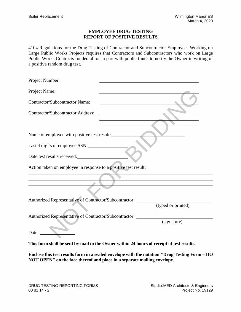
Boiler Replacement Wilmington Manor ES March 4, 2020
DRUG TESTING REPORTING FORMS StudioJAED Architects & Engineers 00 81 14 - 2 Project No. 19129
EMPLOYEE DRUG TESTING
REPORT OF POSITIVE RESULTS
4104 Regulations for the Drug Testing of Contractor and Subcontractor Employees Working on
Large Public Works Projects requires that Contractors and Subcontractors who work on Large
Public Works Contracts funded all or in part with public funds to notify the Owner in writing of
a positive random drug test.
Project Number:
Project Name:
Contractor/Subcontractor Name:
Contractor/Subcontractor Address:
Name of employee with positive test result:
Last 4 digits of employee SSN:
Date test results received:
Action taken on employee in response to a positive test result:
Authorized Representative of Contractor/Subcontractor:
(typed or printed)
Authorized Representative of Contractor/Subcontractor:
(signature)
Date: _______________
This form shall be sent by mail to the Owner within 24 hours of receipt of test results.
Enclose this test results form in a sealed envelope with the notation "Drug Testing Form – DO
NOT OPEN" on the face thereof and place in a separate mailing envelope.
NOT FOR B
IDDIN
G
Wilmington Manor ES Boiler Replacement March 4, 2020
StudioJAED Architects & Engineers AIA CONTRACT FORMS Project No. 19129 00 81 15 - 1
SECTION 00 81 15
CHANGE ORDER AIA G701-2017 AIA Document G701 is for implementing changes in the work agreed by the Owner, Contractor, Construction Manager (if applicable), and Architect. Execution of a completed AIA Document G701 indicated agreement upon all the tenants of the change, including any changes in the Contract Sum (or Guaranteed Maximum Price) and Contract Time. It provides space for the signatures of the Owner, Contractor, Construction Manager (if applicable) and Architect for a complete change. A draft copy of this document is included herein as follows:
NOT FOR B
IDDIN
G

NOT FOR B
IDDIN
G

Wilmington Manor ES Boiler Replacement March 4, 2020
StudioJAED Architects & Engineers AIA CONTRACT FORMS Project No. 19129 00 81 15 - 3
SECTION 00 81 15
CERTIFICATE OF SUBSTANTIAL COMPLETION AIA G704-2017 AIA Document G704 is a standard form for recording the date of substantial completion of the work or a designated portion thereof. The Contractor prepares a list of items to be completed or corrected, and the Architect verifies and amends the list. If the Architect finds that the work is substantially complete, the form is prepared for acceptance by the Contractor and the Owner, and the list of items to be completed or corrected is attached. In AIA Document G704 the parties agree on the time allowed for completion or correction of the items, the date when the Owner will occupy, the work or designated portion thereof, and a description of responsibilities of maintenance, heat, utilities, and insurance. A draft copy of this document is included herein as follows:
NOT FOR B
IDDIN
G
NOT FOR B
IDDIN
G
Wilmington Manor ES Boiler Replacement March 4, 2020
StudioJAED Architects & Engineers AIA CONTRACT FORMS Project No. 19129 00 81 15 - 5
SECTION 00 81 15
CONTRACTOR’S AFFIDAVIT OF PAYMENT OF DEBTS AND CLAIMS AIA G706-1994 The Contractor submits this affidavit with the final request for payment, stating that all payrolls, bills for materials and equipment, and other indebtedness connected with the work for which the Owner might be responsible has been paid or otherwise satisfied. AIA Document G706-1994 requires the Contractor to list any indebtedness or known claims in connection with the construction contract that have not been paid or otherwise satisfied. The Contractor may also be required to finish a lien bond or indemnity bond to protect the Owner with respect to each exception. A draft copy of this document is included herein as follows:
NOT FOR B
IDDIN
G
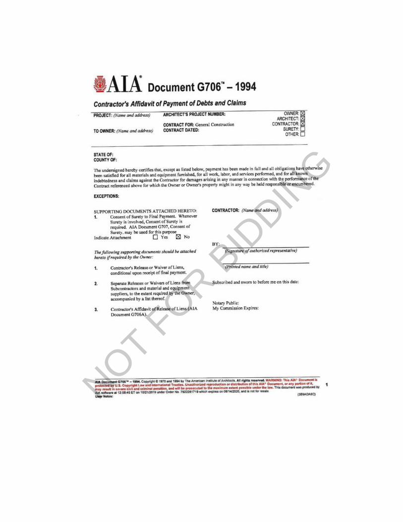
NOT FOR B
IDDIN
G

Wilmington Manor ES Boiler Replacement March 4, 2020
StudioJAED Architects & Engineers AIA CONTRACT FORMS Project No. 19129 00 81 15 - 7
SECTION 00 81 15
CONTRACTOR’S AFFIAVIT OF RELEASE OF LIENS AIA G706A-1994 AIA Document G706A-1994 supports AIA Document G706-1994 in the event that the Owner requires a sworn statement of the Contractor stating that all releases or waivers of liens have been received. In such event, it is normal for the Contractor to submit AIA Documents G706-1994 and G706A-1994 along with attached releases or waivers of liens for the Contractor, all Subcontractors, and others who may have lien rights against the Owner’s property. The Contractor is required to list any exceptions to the sworn statement provided in G706A-1994, and may be required to furnish to the Owner a lien bond or indemnity bond to protect the Owner with respect to such exceptions. A draft copy of this document is included herein as follows:
NOT FOR B
IDDIN
G
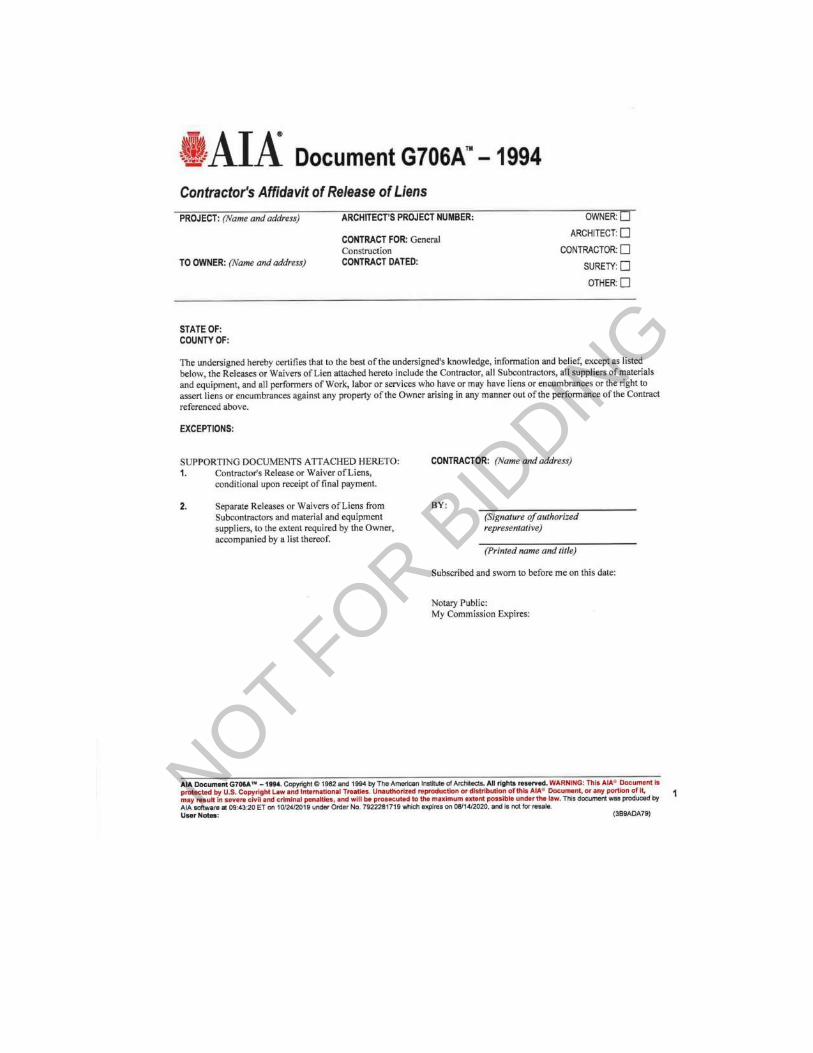
NOT FOR B
IDDIN
G

Wilmington Manor ES Boiler Replacement March 4, 2020
StudioJAED Architects & Engineers AIA CONTRACT FORMS Project No. 19129 00 81 15 - 9
SECTION 00 81 15
CONSENT OF SURETY TO FINAL PAYMENT AIA G707-1994 AIA Document G707-1994 is intended for use as a companion to AIA Document G706-1994, Contractor’s Affidavit of Payment of Debts and Claims, on construction projects where the Contractor is required to furnish a bond. By obtaining the surety’s approval of final payment to the Contractor and its agreement that final payment will no relieve the surety of any of its obligations, the owner may preserve its rights under the bond. A draft copy of this document is included herein as follows:
NOT FOR B
IDDIN
G
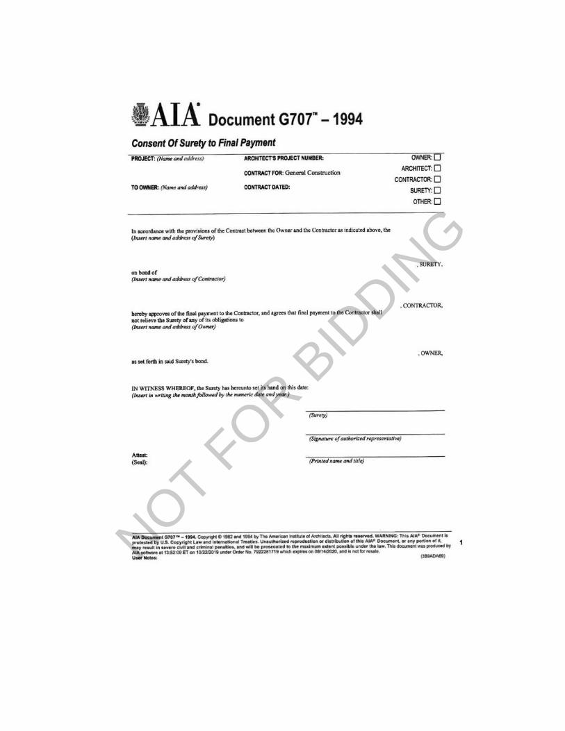
NOT FOR B
IDDIN
G

Wilmington Manor ES Boiler Replacement March 4, 2020
StudioJAED Architects & Engineers AIA CONTRACT FORMS Project No. 19129 00 81 15 - 11
SECTION 00 81 15
ARCHITECT’S SUPPLEMENTAL INSTRUCTIONS AIA G710-2017 AIA Document G710-2017 is used by the Architect o issue additional instructions or interpretations or to order minor changes in the work. It is intended to assist the Architect in performing its obligations as interpreter of the contract documents in accordance with the Owner/Architect agreement and the general conditions of the contract for construction. AIA Document G710-2017 should not be used to change the contract sum or contract time. It is intended to help the Architect perform its services with respect to minor changes not involving adjustment in the contract sum or contract time. Such minor changes are authorized under Section 7.4 of AIA Document A201-2017. A draft copy of this document is included herein as follows:
NOT FOR B
IDDIN
G

NOT FOR B
IDDIN
G

Wilmington Manor ES Boiler Replacement March 4, 2020
StudioJAED Architects & Engineers AIA CONTRACT FORMS Project No. 19129 00 81 15 - 13
SECTION 00 81 15
CONSTRUCTION CHANGE DIRECTIVE AIA G714-2017 AIA Document G714-2017 is a directive for changes in the work for use where the Owner and Contractor have not reached an agreement on proposed changes in the contract sum or contract time. AIA Document G714-2017 was developed as a directive for changes in the work which, if not expeditiously implemented, might delay the project. Upon receipt of a completed G714-2017, the Contractor must promptly proceed with the change in the work described therein. A draft copy of this document is included herein as follows:
NOT FOR B
IDDIN
G

NOT FOR B
IDDIN
G

Wilmington Manor ES Boiler Replacement March 4, 2020
StudioJAED Architects & Engineers AIA CONTRACT FORMS Project No. 19129 00 81 15 - 15
SECTION 00 81 15
ACORD CERTIFICATE OF INSURANCE AIA G715-2017 AIA Document G715-2017 is intended for use in adopting Form 25-S to certify the coverage required of Contractors under AIA Document A201-2017, General Conditions of the Contract for Construction. Since the ACORD certificate does not have space to show all the coverages required in AIA Document A201-2017, the Supplemental Attachment form should be completed, signed by the Contractor’s insurance representative, and attached to the ACORD certificate. A draft copy of this document is included herein as follows:
NOT FOR B
IDDIN
G

NOT FOR B
IDDIN
G

NOT FOR B
IDDIN
G

NOT FOR B
IDDIN
G

Colonial School District Wilmington Manor ES Boiler ReplacementMarch 4, 2020
StudioJAED Architects & EngineersProject No. 19129
SUMMARY01 10 00 - 1
SECTION 01 10 00SUMMARY
PART 1 GENERAL1.01 PROJECT
A. Project Name: Wilmington Manor Elementary School Boiler Replacement.B. Owner's Name: Colonial School District.C. Architect / Engineer's Name: Studio JAED (SJ)D. The Project consists of:
1. Demolition of existing two existing boilers2. Demolition of hot water heating piping, valves, etc.3. Demolition of natural gas piping, valves, etc.4. Demolition of boiler exhaust vent/stack as shown and specified.5. Provide new Boilers as shown and specified.6. Provide new hot water heating piping and insulation, etc. as shown, specified, and required
for proper operation of hot water system along with new boilers.7. Provide new natural gas piping, valves, etc. for new boilers and water heater as shown,
specified, and required for proper operation of new boilers and water heater.8. Provide new exhaust vent/stack as shown, specified, and required for proper operation of
new boilers and water heater.9. Provide new pumps for primary water circulation through new boilers.10. Provide new pumps for secondary water circulation through buildings.11. Provide new controls for new boilers, pumps and water heater
1.02 CONTRACT DESCRIPTIONA. Contract Type: A single prime contract based on a Stipulated Price as described in Division 00.
1.03 DESCRIPTION OF ALTERATIONS WORKA. Scope of demolition and removal work is shown on drawings.B. Scope of renovation work is shown on drawings and included in specifications.
1.04 WORK BY OWNERA. None.
1.05 OWNER OCCUPANCYA. Owner intends to continue to occupy portions of the existing building during the entire
construction period.B. Cooperate with Owner to minimize conflict and to facilitate Owner's operations.C. Schedule the Work to accommodate Owner's occupancy.
1.06 CONTRACTOR USE OF SITE AND PREMISESA. Construction Operations: Limited to the building premises.B. Provide access to and from site as required by law and by Owner:
1. Emergency Building Exits During Construction: Keep all exits required by code openduring construction period; provide temporary exit signs if exit routes are temporarilyaltered.
2. Do not obstruct roadways, sidewalks, or other public ways without permit.3. Adhere to owner's guidelines regarding entrance and egress to the site as identified during
the pre-bid meeting.C. Utility Outages and Shutdown:
NOT FOR B
IDDIN
G

Wilmington Manor ES Boiler Replacement Colonial School DistrictMarch 4, 2020
SUMMARY StudioJAED Architects & Engineers01 10 00 - 2 Project No. 19129
1. Coordinate any interruption and/or shutdown of utilities with the owner at least 7 days inadvance of the anticipated interruption and/or shutdown. Limit anyinterruptions/shutdowns to the absolute minimum amount of time.
2. The owner reserves the right to reschedule construction shutdowns with minimal warningto the contractor as required to respond to emergencies.
1.07 GENERAL STANDARDSA. General Project Requirements
1. Notify the owner in the event any existing hazardous materials, such as asbestos, pcb's,lead, etc., are encountered on the project. The owner will arrange with a qualified specialistfor the identification, testing, removal, handling and protection against exposure orenvironmental pollution, to comply with applicable regulations, laws and ordinances.
2. Prior to submitting bid, the contractor/bidder shall visit the site and be thoroughly familiarwith the existing conditions and proposed construction. Contractor shall include in their bidall material, labor, and all incidentals for a complete installation whether specificallyindicated or not. All errors, discrepancies and missed items shall be brought to theattention of the engineer during the bidding process by the contractor. These items shallbe included in the bid price. No extra cost will be allowed for any discrepancy which couldhave been noticed at the site visit by the contractor.
3. Perform work as required by applicable codes, regulations, and laws of local, state, andfederal governments and other authorities with lawful jurisdiction. All work shall be inaccordance with the latest edition of the national electric code.
4. Material and equipment shall be UL, NEMA, ANSI, IEEE, ADA & CMB approved forintended purpose. Material and installation shall meet requirements of national and localelectrical code.
5. Provide all labor, materials, tools, equipment, coordination, additional design and allincidentals necessary to provide a complete and operable system as detailed on plans tothe satisfaction of the engineer and the owner. Coordinate all work with the engineerbefore the start of work.
6. The contractor shall be responsible for all additional costs incurred as a result ofsubstitutions or deviations from the basis of design shown on these drawings.
7. Give notices, file plans, obtain permits, and licenses, pay fees and back charges, andobtain necessary approvals from authorities that have jurisdiction.
8. Maintain record drawings on site. Record set must be complete and current and availablefor inspection when requisitions for payment are submitted.
9. Guarantee work in writing per specifications, repair or replace defective materials orinstallation at no cost to owner during the guarantee period. Correct damage caused inmaking necessary repairs and replacements under guarantee at no cost to owner. Submitguarantee to owner before final payment.
10. Coordinate all electrical items with existing field conditions. Locations shown areapproximate and may require minor adjustment in the field to satisfy the design intent.
11. Damage to existing facilities and equipment shall be repaired or replaced immediately bythe contractor at no additional expense to the owner.
12. The locations on these plans are approximate and require coordination with all othertrades and verification of existing conditions. The contractor is responsible for fieldverification of all existing associated conditions. Contractor is responsible for obtaining allother trade’s drawings and specifications and coordinating with all other trades duringbidding and construction.
13. Contractor shall be responsible for maintaining continuity of all power, control, fire alarm,security systems, and communications functions to all areas affected by demolition and/ornew construction.
14. Repair and patch any disturbed areas to match adjacent construction.
NOT FOR B
IDDIN
G

Colonial School District Wilmington Manor ES Boiler ReplacementMarch 4, 2020
StudioJAED Architects & EngineersProject No. 19129
SUMMARY01 10 00 - 3
15. Disconnect and make safe any equipment to be removed by others. Coordinate removal ofequipment with other trades prior to demolition.
16. In any area requiring the performance of any trade’s work, this contractor shall carefullyremove and store any or all electrical items in path of work, reinstalling, and reconnectingsame as required, in accordance with the plans and/or as directed after completion ofother trade’s work in that area.
17. Prior to the start of demolition, contractor shall field verify all branch circuits and maintainthose circuits that extend outside the scope of work.
18. After renovating existing electrical work, the contractor shall ensure that all remaining andnew equipment will operate properly, including but not limited to backfeeding of existingpower and lighting circuits. Refer to single line diagram.
19. All electrical work indicated to remain shall be suitably protected to prevent any damage.20. Where electrical systems pass through renovated areas to serve other portions of the
premises, systems shall be suitably protected to prevent damage or relocated and thesystems restored to normal operation. Any outages in systems shall be coordinated withowner. Restore power to existing to remain equipment if interrupted by demolished circuitsin the area.
21. Contractor shall submit for review, shop drawings for all equipment and materials used onthe project. Submittals shall be reviewed by the architect before purchase of materials.
22. All wiring shall be copper, 600v, 75°/90° rated, flame-retardent, heat and moistureresistant.
23. Permanently label all new electrical equipment, including but not limited to, devicedesignation and supply circuit designation. Update or replace panel directories to includenew circuit information resulting from this project.
24. Provide temporary power and lighting for all trades as required to complete the project. Alltemporary and interim equipment shall be installed in accordance with all applicable codesand standards including, but not limited to NFPA 110 and NFPA 70.
25. Refer to specifications for additional information that is not shown on the drawings.26. Openings in existing concrete walls and floors required for conduit installation shall be core
drilled. Maximum core drill size shall be 5” in diameter. Core drill locations shall be spaceda minimum of 6” from each other measured from the outside edge of the core drill. All coredrill openings shall be properly sealed according to their location and application.
27. All outages shall be kept to a minimum. All work that requires a sustained equipmentoutage shall be performed continuously around the clock until work is completed unlessnoted otherwise. Coordinate outages with owner representative.
28. Provide for each branch circuit and feeder circuit a dedicated equipment ground wire. Forsingle phase branch circuits of 120 v/1ph or 277v/1 phase, provide dedicated hot,dedicated neutral and dedicated equipment ground wires. Sharing of neutral or equipmentground wires is not permitted. Wiring to all HVAC equipment or other trade equipmentshall be in conduit. All equipment and feeder wiring in boiler room/electrical room shall bein rigid conduit. Use of mc cable is limited to branch circuit wiring above recessed ceiling orconcealed in wall. Wiring to outlets on table shall be provide in either EMT conduit orflexible metal conduit.
29. Provide identification labels for all branch circuits and feeders circuits at junction boxes,panelboards, troughs, and splice boxes.
30. Provide unspliced feeders from panelboard or switchboard to all equipment. Splicing ispermitted for single phase circuits for lighting and outlets only.
31. All wiring devices located in the basement are to be surface mounted with circuit wiringrouted in surface mounted conduit per specifications. All other wiring devices shall berecessed unless noted otherwise.
END OF SECTION
NOT FOR B
IDDIN
G

NOT FOR B
IDDIN
G

Colonial School District Wilmington Manor ES Boiler ReplacementMarch 4, 2020
StudioJAED Architects & EngineersProject No. 19129
PRICE AND PAYMENTPROCEDURES
01 20 00 - 1
SECTION 01 20 00PRICE AND PAYMENT PROCEDURES
PART 1 GENERAL1.01 SECTION INCLUDES
A. Procedures for preparation and submittal of applications for progress payments.B. Change procedures.
1.02 SCHEDULE OF VALUESA. Electronic media printout including equivalent information will be considered in lieu of standard
form specified; submit sample to Architect for approval.B. Forms filled out by hand will not be accepted.
1.03 APPLICATIONS FOR PROGRESS PAYMENTSA. Payment Period: Submit at intervals stipulated in the Agreement.B. Electronic media printout including equivalent information will be considered in lieu of standard
form specified; submit sample to Architect for approval.C. Forms filled out by hand will not be accepted.D. Execute certification by signature of authorized officer.E. Submit three copies of each Application for Payment.
1.04 MODIFICATION PROCEDURESA. For minor changes not involving an adjustment to the Contract Price or Contract Time, Architect
will issue instructions directly to Contractor.B. For other required changes, Architect will issue a document signed by Owner instructing
Contractor to proceed with the change, for subsequent inclusion in a Change Order.1. The document will describe the required changes and will designate method of
determining any change in Contract Price or Contract Time.2. Promptly execute the change.
C. For changes for which advance pricing is desired, Architect will issue a document that includesa detailed description of a proposed change with supplementary or revised drawings andspecifications, a change in Contract Time for executing the change with a stipulation of anyovertime work required and the period of time during which the requested price will beconsidered valid. Contractor shall prepare and submit a fixed price quotation within 5 days.
D. Computation of Change in Contract Amount: As specified in the Agreement and Conditions ofthe Contract.
E. Execution of Change Orders: Architect will issue Change Orders for signatures of parties asprovided in the Conditions of the Contract.
END OF SECTIONNOT FOR B
IDDIN
G

NOT FOR B
IDDIN
G

Colonial School District Wilmington Manor ES Boiler ReplacementMarch 4, 2020
StudioJAED Architects & EngineersProject No. 19129
ALLOWANCES01 21 00 - 1
SECTION 01 21 00ALLOWANCES
PART 1 GENERAL1.01 SECTION INCLUDES
A. Contingency allowance.B. Payment and modification procedures relating to allowances.
1.02 RELATED REQUIREMENTSA. Section 01 20 00 - Price and Payment Procedures: Additional payment and modification
procedures.1.03 CONTINGENCY ALLOWANCE
A. Funds will be drawn from the Contingency Allowance only by Change Order.B. Contingincy allowance is not to be used for any portion of work indicated in the project
documents. The allowance is to be used by written approval only for unforeseen conditionsrelated to correction of existing condtions to conform with project requirements or coderequirements..
C. At closeout of Contract, funds remaining in Contingency Allowance will be credited to Owner byChange Order.
PART 2 PRODUCTS - NOT USEDPART 3 EXECUTION - NOT USED
END OF SECTION
NOT FOR B
IDDIN
G

NOT FOR B
IDDIN
G

Colonial School District Wilmington Manor ES Boiler ReplacementMarch 4, 2020
StudioJAED Architects & EngineersProject No. 19129
ADMINISTRATIVEREQUIREMENTS
01 30 00 - 1
SECTION 01 30 00ADMINISTRATIVE REQUIREMENTS
PART 1 GENERAL1.01 SECTION INCLUDES
A. Preconstruction meeting.B. Site mobilization meeting.C. Progress meetings.D. Submittals for review, information, and project closeout.E. Number of copies of submittals.F. Requests for Information (RFI) procedures.G. Submittal procedures.
PART 3 EXECUTION2.01 PRECONSTRUCTION MEETING
A. Owner will schedule a meeting after Notice of Award.B. Attendance Required:
1. Owner.2. Architect.3. Contractor.
C. Agenda:1. Execution of Owner-Contractor Agreement.2. Submission of executed bonds and insurance certificates.3. Distribution of Contract Documents.4. Submission of list of Subcontractors, list of Products, schedule of values, and progress
schedule.5. Designation of personnel representing the parties to Contract, OMB and Architect.6. Procedures and processing of field decisions, submittals, substitutions, applications for
payments, proposal request, Change Orders, and Contract closeout procedures.7. Scheduling.
D. Record minutes and distribute copies within two days after meeting to participants, with twocopies to Architect, Owner, participants, and those affected by decisions made.
2.02 SITE MOBILIZATION MEETINGA. Owner will schedule a meeting at the Project site prior to Contractor occupancy.B. Attendance Required:
1. Contractor.2. Owner.3. Architect.4. Contractor's Superintendent.5. Contractor's Project Manager.6. Major Subcontractors.
C. Agenda:1. Use of premises by Owner and Contractor.2. Owner's requirements and occupancy prior to completion.3. Construction facilities and controls provided by Contractor and Owner.4. Security and housekeeping procedures.
NOT FOR B
IDDIN
G

Wilmington Manor ES Boiler Replacement Colonial School DistrictMarch 4, 2020
ADMINISTRATIVE REQUIREMENTS StudioJAED Architects & Engineers01 30 00 - 2 Project No. 19129
5. Schedules.6. Application for payment procedures.7. Procedures for maintaining record documents.8. Requirements for start-up of equipment.
D. Record minutes and distribute copies within two days after meeting to participants, with twocopies to Architect, Owner, participants, and those affected by decisions made.
2.03 PROGRESS MEETINGSA. Schedule and administer meetings throughout progress of the Work at maximum monthly
intervals.B. Attendance Required: Job superintendent, major Subcontractors and suppliers, Owner, and
Architect, as appropriate to agenda topics for each meeting.C. Agenda:
1. Review minutes of previous meetings.2. Review of Work progress.3. Field observations, problems, and decisions.4. Identification of problems that impede, or will impede, planned progress.5. Review of submittals schedule and status of submittals.6. Review of RFIs log and status of responses.7. Maintenance of progress schedule.8. Corrective measures to regain projected schedules.9. Planned progress during succeeding work period.10. Maintenance of quality and work standards.11. Effect of proposed changes on progress schedule and coordination.12. Other business relating to Work.
D. Record minutes and distribute copies within two days after meeting to participants, with twocopies to Architect, Owner, participants, and those affected by decisions made.
2.04 CONSTRUCTION PROGRESS SCHEDULEA. Within 10 days after date of the Agreement, submit preliminary schedule defining planned
operations for the first 60 days of Work, with a general outline for remainder of Work.2.05 REQUESTS FOR INFORMATION (RFI)
A. Definition: A request seeking one of the following:1. An interpretation, amplification, or clarification of some requirement of Contract
Documents arising from inability to determine from them the exact material, process, orsystem to be installed; or when the elements of construction are required to occupy thesame space (interference); or when an item of work is described differently at more thanone place in the Contract Documents.
B. Whenever possible, request clarifications at the next appropriate project progress meeting, withresponse entered into meeting minutes, rendering unnecessary the issuance of a formal RFI.
C. Preparation: Prepare an RFI immediately upon discovery of a need for interpretation of theContract Documents. Failure to submit a RFI in a timely manner is not a legitimate cause forclaiming additional costs or delays in execution of the work.1. Prepare a separate RFI for each specific item.
a. Review, coordinate, and comment on requests originating with subcontractors and/ormaterials suppliers.
b. Do not forward requests which solely require internal coordination betweensubcontractors.
D. Reason for the RFI: Prior to initiation of an RFI, carefully study all Contract Documents toconfirm that information sufficient for their interpretation is definitely not included.
NOT FOR B
IDDIN
G
Colonial School District Wilmington Manor ES Boiler ReplacementMarch 4, 2020
StudioJAED Architects & EngineersProject No. 19129
ADMINISTRATIVEREQUIREMENTS
01 30 00 - 3
1. Include in each request Contractor's signature attesting to good faith effort to determinefrom the Contract Documents information requiring interpretation.
2. Frivolous RFIs: Requests regarding information that is clearly indicated on, or reasonablyinferable from, the Contract Documents, with no additional input required to clarify thequestion. They will be returned without a response, with an explanatory notation.a. The Owner reserves the right to assess the Contractor for the costs (on
time-and-materials basis) incurred by the Architect, and any of its consultants, due toprocessing of such RFIs.
E. Content: Include identifiers necessary for tracking the status of each RFI, and informationnecessary to provide an actionable response.1. Official Project name and number, and any additional required identifiers established in
Contract Documents.2. Owner's, Architect's, and Contractor's names.3. Discrete and consecutive RFI number, and descriptive subject/title.4. Issue date, and requested reply date.5. Reference to particular Contract Document(s) requiring additional
information/interpretation. Identify pertinent drawing and detail number and/or specificationsection number, title, and paragraph(s).
6. Annotations: Field dimensions and/or description of conditions which have engenderedthe request.
7. Contractor's suggested resolution: A written and/or a graphic solution, to scale, is requiredin cases where clarification of coordination issues is involved, for example; routing,clearances, and/or specific locations of work shown diagrammatically in ContractDocuments. If applicable, state the likely impact of the suggested resolution on ContractTime or the Contract Sum.
F. Attachments: Include sketches, coordination drawings, descriptions, photos, submittals, andother information necessary to substantiate the reason for the request.
G. RFI Log: Prepare and maintain a tabular log of RFIs for the duration of the project.1. Indicate current status of every RFI. Update log promptly and on a regular basis.2. Note dates of when each request is made, and when a response is received.3. Highlight items requiring priority or expedited response.4. Identify and include improper or frivolous RFIs.
2.06 SUBMITTALS FOR REVIEWA. When the following are specified in individual sections, submit them for review:
1. Product data.2. Shop drawings.3. Samples for selection.4. Samples for verification.
B. Submit to Architect for review for the limited purpose of checking for conformance withinformation given and the design concept expressed in the contract documents.
C. Samples will be reviewed only for aesthetic, color, or finish selection.D. After review, provide copies and distribute in accordance with SUBMITTAL PROCEDURES
article below and for record documents purposes described in Section 01 78 00 - CloseoutSubmittals.
2.07 SUBMITTALS FOR INFORMATIONA. When the following are specified in individual sections, submit them for information:
1. Design data.2. Certificates.
NOT FOR B
IDDIN
G

Wilmington Manor ES Boiler Replacement Colonial School DistrictMarch 4, 2020
ADMINISTRATIVE REQUIREMENTS StudioJAED Architects & Engineers01 30 00 - 4 Project No. 19129
3. Test reports.4. Inspection reports.5. Manufacturer's instructions.6. Manufacturer's field reports.7. Other types indicated.
B. Submit for Architect's knowledge as contract administrator or for Owner. No action will betaken.
2.08 SUBMITTALS FOR PROJECT CLOSEOUTA. When the following are specified in individual sections, submit them at project closeout:
1. Project record documents.2. Operation and maintenance data.3. Warranties.4. Bonds.5. Other types as indicated.
B. Submit for Owner's benefit during and after project completion.2.09 NUMBER OF COPIES OF SUBMITTALS
A. Documents for Review:1. Small Size Sheets, Not Larger Than 8-1/2 x 11 inches: Submit the number of copies that
Contractor requires, plus two copies that will be retained by Architect.B. Documents for Information: Submit two copies.C. Samples: Submit the number specified in individual specification sections; one of which will be
retained by Architect.1. After review, produce duplicates.2. Retained samples will not be returned to Contractor unless specifically so stated.
2.10 SUBMITTAL PROCEDURESA. General Requirements:
1. Use a separate transmittal for each item.2. Identify: Project; Contractor; subcontractor or supplier; pertinent drawing and detail
number; and specification section number and article/paragraph, as appropriate on eachcopy.
3. Apply Contractor's stamp, signed or initialed certifying that review, approval, verification ofproducts required, field dimensions, adjacent construction work, and coordination ofinformation is in accordance with the requirements of the work and Contract Documents.
4. Deliver each submittal on date noted in submittal schedule, unless an earlier date hasbeen agreed to by all affected parties, and is of the benefit to the project.a. Deliver submittals to Architect at business address.
5. Provide space for Contractor and Architect review stamps.6. When revised for resubmission, identify all changes made since previous submission.7. Distribute reviewed submittals. Instruct parties to promptly report inability to comply with
requirements.B. Shop Drawing Procedures:
1. Prepare accurate, drawn-to-scale, original shop drawing documentation by interpreting theContract Documents and coordinating related work.
2. Generic, non-project-specific information submitted as shop drawings do not meet therequirements for shop drawings.
C. Transmit each submittal with approved form.
NOT FOR B
IDDIN
G
Colonial School District Wilmington Manor ES Boiler ReplacementMarch 4, 2020
StudioJAED Architects & EngineersProject No. 19129
ADMINISTRATIVEREQUIREMENTS
01 30 00 - 5
D. Sequentially number the transmittal form. Revise submittals with original number and asequential alphabetic suffix.
E. Identify Project, Contractor, Subcontractor or supplier; pertinent drawing and detail number, andspecification section number, as appropriate on each copy.
F. Apply Contractor's stamp, signed or initialed certifying that review, approval, verification ofProducts required, field dimensions, adjacent construction Work, and coordination ofinformation is in accordance with the requirements of the Work and Contract Documents.
G. Schedule submittals to expedite the Project, and coordinate submission of related items.H. For each submittal for review, allow 15 days excluding delivery time to and from the Contractor.I. Identify variations from Contract Documents and Product or system limitations that may be
detrimental to successful performance of the completed Work.J. Provide space for Contractor and Architect review stamps.K. When revised for resubmission, identify all changes made since previous submission.L. Distribute reviewed submittals as appropriate. Instruct parties to promptly report any inability to
comply with requirements.M. Submittals not requested will not be recognized or processed.
END OF SECTION
NOT FOR B
IDDIN
G

NOT FOR B
IDDIN
G

Colonial School District Wilmington Manor ES Boiler ReplacementMarch 4, 2020
StudioJAED Architects & EngineersProject No. 19129
QUALITY REQUIREMENTS01 40 00 - 1
SECTION 01 40 00QUALITY REQUIREMENTS
PART 1 GENERAL1.01 SECTION INCLUDES
A. Submittals.B. Quality assurance.C. Control of installation.D. Tolerances.E. Testing and inspection services.F. Manufacturers' field services.
1.02 REFERENCE STANDARDS1.03 SUBMITTALS
A. See Section 01 30 00 - Administrative Requirements, for submittal procedures.B. Testing Agency Qualifications:
1.04 QUALITY ASSURANCEA. Testing Agency Qualifications:
1. Prior to start of work, submit agency name, address, and telephone number, and names offull time registered Engineer and responsible officer.
PART 2 PRODUCTS - NOT USEDPART 3 EXECUTION3.01 CONTROL OF INSTALLATION
A. Monitor quality control over suppliers, manufacturers, products, services, site conditions, andworkmanship, to produce Work of specified quality.
B. Comply with manufacturers' instructions, including each step in sequence.C. Should manufacturers' instructions conflict with Contract Documents, request clarification from
Architect before proceeding.D. Comply with specified standards as minimum quality for the Work except where more stringent
tolerances, codes, or specified requirements indicate higher standards or more preciseworkmanship.
E. Have Work performed by persons qualified to produce required and specified quality.F. Verify that field measurements are as indicated on shop drawings or as instructed by the
manufacturer.G. Secure products in place with positive anchorage devices designed and sized to withstand
stresses, vibration, physical distortion, and disfigurement.3.02 TOLERANCES
A. Monitor fabrication and installation tolerance control of products to produce acceptable Work. Do not permit tolerances to accumulate.
B. Comply with manufacturers' tolerances. Should manufacturers' tolerances conflict with ContractDocuments, request clarification from Architect before proceeding.
C. Adjust products to appropriate dimensions; position before securing products in place.3.03 TESTING AND INSPECTION
A. See individual specification sections for testing required.
NOT FOR B
IDDIN
G

Wilmington Manor ES Boiler Replacement Colonial School DistrictMarch 4, 2020
QUALITY REQUIREMENTS StudioJAED Architects & Engineers01 40 00 - 2 Project No. 19129
B. Re-testing required because of non-conformance to specified requirements shall be performedby the same agency on instructions by Architect.
C. Re-testing required because of non-conformance to specified requirements shall be paid for byContractor.
3.04 MANUFACTURERS' FIELD SERVICESA. When specified in individual specification sections, require material or product suppliers or
manufacturers to provide qualified staff personnel to observe site conditions, conditions ofsurfaces and installation, quality of workmanship, start-up of equipment, test, adjust andbalance of equipment and operation as applicable, and to initiate instructions when necessary.
B. Report observations and site decisions or instructions given to applicators or installers that aresupplemental or contrary to manufacturers' written instructions.
3.05 DEFECT ASSESSMENTA. Replace Work or portions of the Work not conforming to specified requirements.B. If, in the opinion of Architect, it is not practical to remove and replace the Work, Architect will
direct an appropriate remedy or adjust payment.END OF SECTION
NOT FOR B
IDDIN
G

Wilmington Manor ES Boiler Replacement March 4, 2020
StudioJAED Architects & Engineers REFERENCES Project No. 19129 01 42 00 - 1
Section 01 42 00 REFERENCES
PART 1 - GENERAL
1.1 RELATED DOCUMENTS
A. Drawings and general provisions of the Contract, including General and Supplementary Conditions and other Division O 1 Specification Sections, apply to this Section.
1.2 DEFINITIONS
A. General: Basic Contract definitions are included in the Conditions of the Contract.
B. "Approved": When used to convey Architect's action on Contractor's submittals, applications, and requests, "approved" is limited to Architect's duties and responsibilities as stated in the Conditions of the Contract.
C. "Directed": A command or instruction by Architect. Other term including "requested," "authorized," "selected," "approved," "required,'' and "permitted" have the same meaning as "directed."
D. "Indicated": Requirements expressed by graphic representations or in written form on Drawings, in
Specifications, and in other Contract Documents. Other terms including "shown," "noted," "scheduled”, and "specified" have the same meaning as "indicated."
E. "Regulations": Laws, ordinances, statutes, and lawful orders issued by authorities having jurisdiction, and rules,
conventions, and agreements within the construction industry that control performance of the Work.
F. "Furnish": Supply and deliver to Project site, ready for unloading, unpacking, assembly, installation, and similar operations.
G. "Install": Operations at Project site including unloading, temporarily storing, unpacking, assembling, erecting,
placing, anchoring, applying, working to dimension, finishing, curing, protecting, cleaning, and similar operations.
H. "Provide": Furnish and install, complete and ready for the intended use.
I. "Project Site": Space available for performing construction activities. The extent of Project site is shown on Drawings and may or may not be identical with the description of the land on which Project is to be built.
1.3 INDUSTRY STANDARDS
A. Applicability of Standards: Unless the Contract Documents include more stringent requirements,
applicable construction industry standards have the same force and effect as if bound or copied directly into the Contract Documents to the extent referenced. Such standards are made a part of the Contract Documents by reference.
B. Publication Dates: Comply with standards in effect as of date of the contract Documents, unless otherwise indicated.
C. Copies of Standards: Each entity engaged in construction on Project should be familiar with industry standards applicable to its construction activity. Copies of applicable standards are not bound with the Contract Documents. 1. Where copies of standards are needed to perform a required construction activity, obtain copies
directly from publication source. D. Abbreviations and Acronyms for Standards and Regulations: Where abbreviations and acronyms are
used in Specifications or other Contract Documents, they shall mean the recognized name of the standards and regulations in the following list. Names, telephone numbers, and Web site addresses are subject to change.
NOT FOR B
IDDIN
G

Boiler Replacement Wilmington Manor ES March 4, 2020
REFERENCES StudioJAED Architects & Engineers 01 42 00 - 2 Project No. 19129
ADAAG Americans with Disabilities Act (ADA)
Architectural Barriers Act (ABA) Accessibility Guidelines for Buildings and Facilities Available from Access Board www.access-board.gov
800-872-2253 202-272-0050
CFR Code of Federal Regulations
Available from Government Print Office www.gpoaccess.gov/cfr/index/html
888-293-6498 202-512-1530
CRD Handbook for Concrete and Cement
Available from Army Corps of Engineers Waterways Experiment Station www.wes.army.mil
601-634-2355
DOD Department of Defense Military Specifications and Standards
Available from Department of Defense Single Stock Point www.dodssp.daps.mil
215-697-6257
DSCC Defense Supply Center Columbus
(See FS)
FED-STD Federal Standard
(See FS)
FS Federal Specification
Available from Department of Defense Single Stock Point www.dodssp.daps.mil Available from General Services Administration www.fss.gsa.gov Available from National Institute of Building Services ww.nibs.org
215-697-6257 202-501-1021 202-289-7800
FTMS Federal Test Method Standard
(See FS)
ICC-ES ICC Evaluation Services, Inc.
www.icc-es.org 800-423-6587
MIL-STD (See MILSPEC) MILSPEC Military Specification and Standards
Available from Department of Defense Single Stock Point www.dodssp.daps.mil
215-697-6257
NES (Formerly: National Evaluation Service)
(See ICC-ES)
UFAS Uniform Federal Accessibility Standards
Available from Access Board www.access-board.gov
800-872-2253 202-272-0080
NOT FOR B
IDDIN
G

Wilmington Manor ES Boiler Replacement March 4, 2020
StudioJAED Architects & Engineers REFERENCES Project No. 19129 01 42 00 - 3
1.4 ABBREVIATIONS AND ACRONYMS
A. Industry Organizations: Where abbreviations and acronyms are used in Specifications or other Contract Documents, they shall mean the recognized name of the entities indicated in Gale Research's "Encyclopedia of Associations" or in Columbia Books' ''National Trade & Professional Associations of the U.S."
B. Industry Organizations: Where abbreviations and acronyms are used in Specifications or other Contract
Documents, they shall mean the recognized name of the entities in the following list. Names, telephone numbers, and Web-site addresses are subject to change.
AA Aluminum Association, Inc. (The)
www.aluminum.org 202-862-5100
AABC Associated Air Balance Council
www.aabchq.com 202-737-0202
AAMA American Architectural Manufacturers Association
Transportation Officials www.transportation.org
202-624-5800
AASHTO American Association of State Highway and
Transportation Officials www.transportation.org
202-624-5800
AATCC American Association of Textile Chemists and Colorists (The)
www.aatcc.org 919-549-8141
ABMA American Bearing Manufacturers Association
www.abma-dc.org 202-367-1155
ACI ACI International (American Concrete Institute) www.aci-int.org
248-848-3700
ACPA American Concrete Pipe Association
www.concrete-pipe.org 972-506-7216
AEIC Association of Edison Illuminating Companies, Inc. (The)
www.aeic.org 205-257-2530
AF&PA American Forest & Paper Association
www.afandpa.org 800-878-8878 202-463-2700
AGA American Gas Association
www.aga.org 202-824-7000
AGC Associated General Contractors of America (The) www.agc.org
703-548-3118
AHA American Hardboard Association (Now part of CPA)
AI Asphalt Institute www.asphaltinstitute.org
859-288-4960
NOT FOR B
IDDIN
G

Boiler Replacement Wilmington Manor ES March 4, 2020
REFERENCES StudioJAED Architects & Engineers 01 42 00 - 4 Project No. 19129
AIA American Institute of Architects (The) www.aia.org
800-242-3837 202-626-7300
AISC American Institute of Steel Construction www.aisc.org
800-644-2400 312-670-2400
AISI American Iron and Steel Institute www.steel.org
202-452-7100
AITC American Institute of Timber Construction www.aitc-glulam.org
303-792-9559
ALCA Associated Landscape Contractors of America www.alca.org
800-395-2522 703-136-9666
ALSC American Lumber Standard Committee, Inc. www.alsc.org
301-972-1700
AMCA Air Movement and Control Association International, Inc. www.amca.org
847-394-0150
ANSI American National Standards Institute www.ansi.org
202-293-8020
AOSA Association of Official Seed Analysts www.aosaseed.com
505-522-1437
APA The Engineered Wood Association www.apawood.org
253-565-6600
APA Architectural Precast Association www.archprecast.org
239-454-6989
API American Petroleum Institute www.api.org
202-682-8000
ARI Air Conditioning & Refrigeration Institute www.ari.org
703-524-8800
ARMA Asphalt Roofing Manufacturers Association www.asphaltroofing.org
202-207-0917
ASCE American Society of Civil Engineers www.asce.org
800-548-2723 703-295-6300
ASHRAE American Society of Heating, Refrigeration and Air Conditioning Engineers
800-527-4723 404-636-8400
NOT FOR B
IDDIN
G

Wilmington Manor ES Boiler Replacement March 4, 2020
StudioJAED Architects & Engineers REFERENCES Project No. 19129 01 42 00 - 5
www.ashrae.org
ASME The American Society of Mechanical Engineers International www.asme.org
800-843-2763 212-591-7722
ASSE American Society of Sanitary Engineering www.asse-plumbing.org
440-835-3040
ASTM American Society for Testing and Materials International www.astm.org
610-832-9585
AWCI Association of the Wall and Ceiling Industries International www.awci.org
703-534-8300
AWCMA American Window Covering Manufacturers Association (Now WCSC)
AWI Architectural Woodwork Institute www.awinet.org
800-449-8811 703-733-0600
AWPA American Wood-Preservers’ Association www.awpa.com
334-874-9800
AWS American Welding Society www.aws.org
800-443-9353 305-443-9353
AWWA American Water Works Association www.awwa.org
800-926-7337 303-794-7711
BHMA Builders Hardware Manufacturers Association www.buildershardware.com
212-297-2122
BIA Brick Industry Association (The) www.bia.org
703-620-0010
BIFMA Business and Institutional Furniture Manufacturer’s Association International www.bifma.com
616-285-3963
Cast Stone Institute www.caststone.org
770-972-3011
CCC Carpet Cushion Council www.carpetcushion.org
203-637-1312
CDA Copper Development Association Inc. www.copper.org
800-232-3282 212-251-7200
NOT FOR B
IDDIN
G
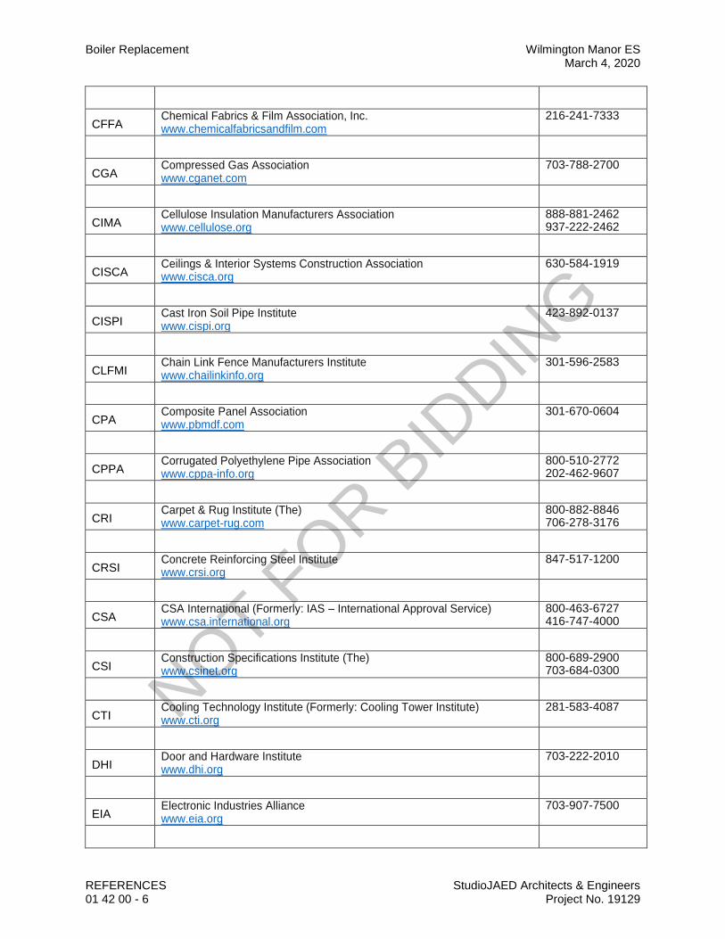
Boiler Replacement Wilmington Manor ES March 4, 2020
REFERENCES StudioJAED Architects & Engineers 01 42 00 - 6 Project No. 19129
CFFA Chemical Fabrics & Film Association, Inc. www.chemicalfabricsandfilm.com
216-241-7333
CGA Compressed Gas Association www.cganet.com
703-788-2700
CIMA Cellulose Insulation Manufacturers Association www.cellulose.org
888-881-2462 937-222-2462
CISCA Ceilings & Interior Systems Construction Association www.cisca.org
630-584-1919
CISPI Cast Iron Soil Pipe Institute www.cispi.org
423-892-0137
CLFMI Chain Link Fence Manufacturers Institute www.chailinkinfo.org
301-596-2583
CPA Composite Panel Association www.pbmdf.com
301-670-0604
CPPA Corrugated Polyethylene Pipe Association www.cppa-info.org
800-510-2772 202-462-9607
CRI Carpet & Rug Institute (The) www.carpet-rug.com
800-882-8846 706-278-3176
CRSI Concrete Reinforcing Steel Institute www.crsi.org
847-517-1200
CSA CSA International (Formerly: IAS – International Approval Service) www.csa.international.org
800-463-6727 416-747-4000
CSI Construction Specifications Institute (The) www.csinet.org
800-689-2900 703-684-0300
CTI Cooling Technology Institute (Formerly: Cooling Tower Institute) www.cti.org
281-583-4087
DHI Door and Hardware Institute www.dhi.org
703-222-2010
EIA Electronic Industries Alliance www.eia.org
703-907-7500
NOT FOR B
IDDIN
G
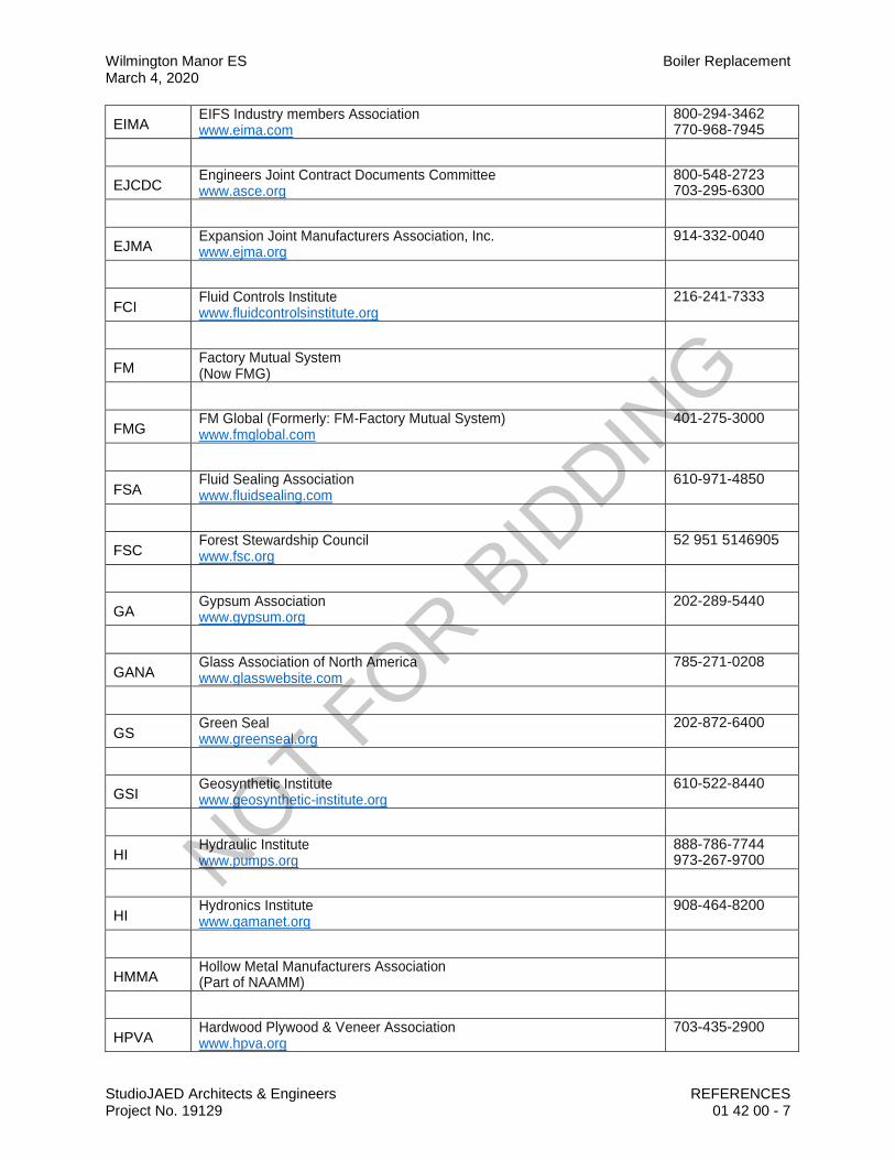
Wilmington Manor ES Boiler Replacement March 4, 2020
StudioJAED Architects & Engineers REFERENCES Project No. 19129 01 42 00 - 7
EIMA EIFS Industry members Association www.eima.com
800-294-3462 770-968-7945
EJCDC Engineers Joint Contract Documents Committee www.asce.org
800-548-2723 703-295-6300
EJMA Expansion Joint Manufacturers Association, Inc. www.ejma.org
914-332-0040
FCI Fluid Controls Institute www.fluidcontrolsinstitute.org
216-241-7333
FM Factory Mutual System (Now FMG)
FMG FM Global (Formerly: FM-Factory Mutual System) www.fmglobal.com
401-275-3000
FSA Fluid Sealing Association www.fluidsealing.com
610-971-4850
FSC Forest Stewardship Council www.fsc.org
52 951 5146905
GA Gypsum Association www.gypsum.org
202-289-5440
GANA Glass Association of North America www.glasswebsite.com
785-271-0208
GS Green Seal www.greenseal.org
202-872-6400
GSI Geosynthetic Institute www.geosynthetic-institute.org
610-522-8440
HI Hydraulic Institute www.pumps.org
888-786-7744 973-267-9700
HI Hydronics Institute www.gamanet.org
908-464-8200
HMMA Hollow Metal Manufacturers Association (Part of NAAMM)
HPVA Hardwood Plywood & Veneer Association www.hpva.org
703-435-2900
NOT FOR B
IDDIN
G

Boiler Replacement Wilmington Manor ES March 4, 2020
REFERENCES StudioJAED Architects & Engineers 01 42 00 - 8 Project No. 19129
HPW H.P. White Laboratory, Inc. www.hpwhite.com
410-838-6550
IAS International Approval Services (Now CSA International)
ICEA Insulated Cable Engineers Association, Inc. www.icea.net
770-830-0369
ICRI International Concrete Repair Institute, Inc. www.icri.org
847-827-0830
IEC International Electrotechnical Commission www.iec.ch
41 22 919 02 11
IEEE Institute of Electrical and Electronics Engineers, Inc. www.ieee.org
212-419-7900
IESNA Illuminating Engineering Society of North America www.iesna.org
212-248-5000
IGCC Insulating Glass Certification Council www.igcc.org
315-646-2234
IGMA Insulating Glass Manufacturers Alliance www.igmaonline.org
613-233-1510
ILI Indiana Limestone Institute of America, Inc. www.iliai.com
812-275-4426
ISO International Organization for Standardization www.iso.ch
41 22 749 01 11
ISSFA International Solid Surface Fabricators Association www.issfa.net
702-567-8150
ITU International Telecommunication Union www.itu.int/home
41 22 730 51 11
KCMA Kitchen Cabinet Manufacturers Association www.kcma.org
703-264-1690
LMA Laminating Materials Association (Now part of CPA)
NOT FOR B
IDDIN
G
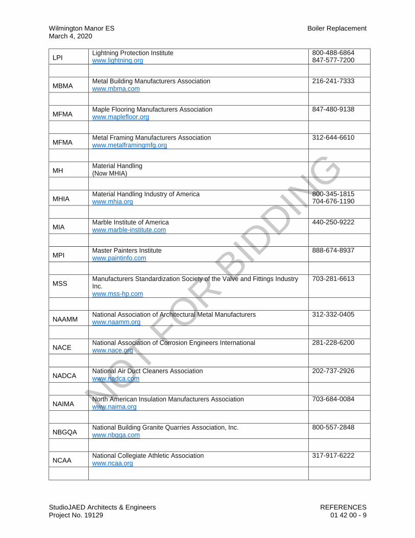
Wilmington Manor ES Boiler Replacement March 4, 2020
StudioJAED Architects & Engineers REFERENCES Project No. 19129 01 42 00 - 9
LPI Lightning Protection Institute www.lightning.org
800-488-6864 847-577-7200
MBMA Metal Building Manufacturers Association www.mbma.com
216-241-7333
MFMA Maple Flooring Manufacturers Association www.maplefloor.org
847-480-9138
MFMA Metal Framing Manufacturers Association www.metalframingmfg.org
312-644-6610
MH Material Handling (Now MHIA)
MHIA Material Handling Industry of America www.mhia.org
800-345-1815 704-676-1190
MIA Marble Institute of America www.marble-institute.com
440-250-9222
MPI Master Painters Institute www.paintinfo.com
888-674-8937
MSS Manufacturers Standardization Society of the Valve and Fittings Industry Inc. www.mss-hp.com
703-281-6613
NAAMM National Association of Architectural Metal Manufacturers www.naamm.org
312-332-0405
NACE National Association of Corrosion Engineers International www.nace.org
281-228-6200
NADCA National Air Duct Cleaners Association www.nadca.com
202-737-2926
NAIMA North American Insulation Manufacturers Association www.naima.org
703-684-0084
NBGQA National Building Granite Quarries Association, Inc. www.nbgqa.com
800-557-2848
NCAA National Collegiate Athletic Association www.ncaa.org
317-917-6222
NOT FOR B
IDDIN
G
Boiler Replacement Wilmington Manor ES March 4, 2020
REFERENCES StudioJAED Architects & Engineers 01 42 00 - 10 Project No. 19129
NCMA National Concrete Masonry Association www.ncma.org
703-713-1900
NCPI National Clay Pipe Institute www.ncpi.org
262-248-9094
NCTA National Cable & Telecommunications Association www.ncta.com
202-775-3550
NEBB National Environmental Balancing Bureau www.nebb.org
301-977-3698
NECA National Electrical Contractors Association www.necanet.org
301-657-3110
NELMA Northeastern Lumber Manufacturers’ Association www.nelma.org
207-829-6901
NEMA National Electrical Manufacturers Association www.nema.org
703-847-3200
NETA International Electrical Testing Association www.netaworld.org
303-697-8441
NFHS National Federation of State High School Associations www.nfhs.org
317-972-6900
NFPA National Fire Protection Association www.nfpa.org
800-344-3555 617-770-3000
NFRC National Fenestration Rating Council www.nfrc.org
301-589-1776
NGA National Glass Association www.glass.org
703-442-4890
NHLA National Hardwood Lumber Association www.natlhardwood.org
800-933-0318 901-377-1818
NLGA National Lumber Grades Authority www.nlga.org
604-524-2393
NOFMA National Oak Flooring Manufacturers Association www.nofma.org
901-526-5016
NRCA National Roofing Contractors Association www.nrca.net
800-323-9545 847-299-9070
NOT FOR B
IDDIN
G

Wilmington Manor ES Boiler Replacement March 4, 2020
StudioJAED Architects & Engineers REFERENCES Project No. 19129 01 42 00 - 11
NRMCA National Ready Mixed Concrete Association www.nrmca.org
888-846-7622 301-587-1400
NSF National Sanitation Foundation International www.nsf.org
800-673-6275 734-769-8010
NSSGA National Stone, Sand & Gravel Association www.nssga.org
800-342-1415 703-525-8788
NTMA National Terrazzo & Mosaic Association, Inc. www.ntma.com
800-323-9736 540-751-0930
NTRMA National Tile Roofing Manufacturers Association (Now TRI)
NWWDA National Wood Window and Door Association (Now WDMA)
OPL Omega Point Laboratories, Inc. www.opl.com
800-966-5253 210-635-8100
PCI Precast/Prestressed Concrete Institute www.pci.org
312-786-0300
PDCA Painting & Decorating Contractors of America www.pdca.com
800-332-7322 314-514-7322
PDI Plumbing & Drainage Institute www.pdionline.org
800-589-8956 978-557-0720
PGI PVC Geomembrane Institute http://pgi-to.ce.uiuc.edu
217-333-3929
PTI Post Tensioning Institute www.post-tensioning.org
602-870-7540
RCSC Research Council on Structural Connections www.boltcouncil.org
800-644-2400 312-670-2400
RFCI Resilient Floor Covering Institute www.rfci.com
301-340-8580
RIS Redwood Inspection Service www.calredwood.org
888-225-7339 415-382-0662
NOT FOR B
IDDIN
G

Boiler Replacement Wilmington Manor ES March 4, 2020
REFERENCES StudioJAED Architects & Engineers 01 42 00 - 12 Project No. 19129
SAE SAE International www.sae.org
724-776-4841
SDI Steel Deck Institute www.sdi.org
847-462-1930
SDI Steel Door Institute www.steeldoor.org
440-899-0010
SEFA Scientific Equipment and Furniture Association www.sefalabs.com
516-294-5424
SEI Structural Engineering Institute www.seinstitute.com
800-548-2723 703-295-6195
SGCC Safety Glazing Certification Council www.sgcc.org
315-646-2234
SIA Security Industry Association www.siaonline.org
703-683-2075
SIGMA Sealed Insulating Glass Manufacturers Association (Now IGMA)
SJI Steel Joist Institute www.steeljoist.org
843-626-1995
SMA Screen Manufacturers Association www.smacentral.org
561-533-0991
SMACNA Sheet Metal and Air Conditioning Contractors’ National Association www.smacna.org
703-803-2980
SMPTE Society of Motion Picture and Television Engineers www.smpte.org
914-761-1100
SPFA Spray Polyurethane Foam Alliance (Formerly: SPIB/SPFD – The Society of the Plastics Industry, Inc.; Spray Polyurethane Foam Division) www.sprayfoam.org
800-523-6154
SPID Southern Pine Inspection Bureau www.spib.org
850-434-2611
SPI/SPFD Society of the Plastics Industry, Inc. Spray Polyurethane Foam Division
NOT FOR B
IDDIN
G
Wilmington Manor ES Boiler Replacement March 4, 2020
StudioJAED Architects & Engineers REFERENCES Project No. 19129 01 42 00 - 13
(Now SPFA)
SPRI Single Ply Roofing Institute www.spri.org
781-647-7026
SSINA Specialty Steel Industry of North America www.ssina.com
800-982-0355 202-342-8630
SSPC The Society for Protective Coatings www.sspc.org
877-281-7772 412-281-2331
STI Steel Tank Institute www.steeltank.com
847-438-8265
SWI Steel Window Institute www.steelwindows.com
216-241-7333
SWRI Sealant, Waterproofing & Restoration Institute www.swrionline.org
816-472-7974
TCA Tile Council of America, Inc. www.tileusa.com
864-646-8453
TIA/EIA Telecommunications Industry Association/Electronic Industries Alliance www.tiaonline.org
703-907-7700
TMS The Masonry Society www.masonrysociety.org
303-939-9700
TPI Truss Plate Institute, Inc. www.tpinst.org
608-833-5900
TRI Tile Roofing Institute (Formerly: RTI – Roof Tile Institute) www.tileroofing.org
312-670-4177
UL Underwriters Laboratories Inc. www.ul.com
800-285-4476 847-272-8800
UNI Uni-Bell PVC Pipe Association www.uni-bell.org
972-243-3902
USGBC US Green Building Council www.usgbc.org
202-828-7422
USITT US Institute for Theatre Technology, Inc. www.usitt.org
800-938-7488 315-463-6463
NOT FOR B
IDDIN
G

Boiler Replacement Wilmington Manor ES March 4, 2020
REFERENCES StudioJAED Architects & Engineers 01 42 00 - 14 Project No. 19129
WASTEC Waste Equipment Technology Association www.wastec.org
800-424-2869 202-244-4700
WCLIB West Coast Lumber Inspection Bureau www.wclib.org
800-283-1486 503-639-0651
WCMA Window Covering Manufacturers Association (Now WCSC)
WCSC Window Covering Safety Council (Formerly: WCMA – Window Covering Manufacturers Association) www.windowcoverings.org
800-506-4636 212-661-4261
WDMA Window & Door Manufacturers Association (Formerly: NWWDA – National Wood Window and Door Association) www.wdma.com
800-223-2301 847-299-5200
WI Woodwork Institute (Formerly: WIC – Woodwork Institute of California) www.wicnet.org
916-372-9943
WIC Woodwork Institute of California (Now WI)
WMMPA Wood Moulding & Millwork Producers Association www.wmmpa.com
800-550-7889 530-661-9591
WSRCA Western States Roofing Contractors Association www.wsrca.com
800-725-0333 650-548-0112
WWPA Western Wood Products Association www.wwpa.org
503-224-3930
C. Code Agencies: Where abbreviations and acronyms are used in Specifications or other
Contract Documents, they shall mean the recognized name of the entities in the following list. Names, Telephone numbers, and Web-site address are subject to change.
BOCA BOCA International, Inc. (See ICC)
CABO Council of American Building Officials See ICC)
IAPMO International Association of Plumbing and Mechanical Officials www.iapmo.org
909-472-4100
NOT FOR B
IDDIN
G

Wilmington Manor ES Boiler Replacement March 4, 2020
StudioJAED Architects & Engineers REFERENCES Project No. 19129 01 42 00 - 15
ICBO International Conference of Building Officials (See ICC)
ICBO ES ICBO Evaluation Service, Inc. (See ICC-ES)
ICC International Code Council (Formerly: CABO – Council of American Building Officials) www.iccsafe.org
703-931-4533
ICC-ES ICC Evaluation Service, Inc. www.icc-es.org
800-423-6587 562-699-0543
NES National Evaluation Service (See ICC-ES)
SBCCI Southern Building Code Congress International, Inc. (See ICC)
D. Federal Government Agencies: Where abbreviations and acronyms are used in
Specifications or other Contract Documents, they shall mean the recognized name of the entities in the following list. Names, Telephone numbers, and Web-site address are subject to change.
CE Army Corps of Engineers www.usace.army.mil
CPSC Consumer Product Safety Commission www.cpsc.gov
800-638-2772 301-504-6816
DOC Department of Defense www.dodssp.daps.mil
215-697-6257
DOD Department of Defense www.dodssp.daps.mil
215-697-6257
DOE Department of Energy www.eren.doe.gov
202-586-9220
EPA Environmental Protection Agency www.epa.gov
202-272-0167
FAA Federal Aviation Administration www.faa.gov
202-366-4000
FCC Federal Communications Commission www.fcc.gov
888.225-5322
NOT FOR B
IDDIN
G

Boiler Replacement Wilmington Manor ES March 4, 2020
REFERENCES StudioJAED Architects & Engineers 01 42 00 - 16 Project No. 19129
FDA Food and Drug Administration www.fda.gov
888-463-6332
GSA General Services Administration www.gsa.gov
800-488-3111 202-501-1888
HUD Department of Housing and Urban Development www.hud.gov
202-708-1112
LBL Lawrence Berkeley National Laboratory www.lbl.gov
510-486-4000
NCHRP National Cooperative Highway Research Program (See TRB)
NIST National Institute of Standards and Technology www.nist.gov
301-975-6478
OSHA Occupational Safety & Health Administration www.osha.gov
800-321-6742 202-693-1999
PBS Public Building Service (See GSA)
PHS Office of Public Health and Science http://phs.os.dhhs.gov
202-690-7694
RUS Rural Utilities Service (See USDA)
202-720-9540
SD State Department www.state.gov
202-647-4000
TRB Transportation Research Board www.nas.edu.trb
202-334-2934
USDA Department of Agriculture www.usda.gov
202-720-2791
USPS Postal Service www.usps.com
202-268-2000
NOT FOR B
IDDIN
G
Wilmington Manor ES Boiler Replacement March 4, 2020
StudioJAED Architects & Engineers REFERENCES Project No. 19129 01 42 00 - 17
E. State Government Agencies: Where abbreviations and acronyms are used in Specifications or other Contract Documents, they shall mean the recognized name of the entities in the following list. Names, telephone numbers, and Website addresses are subject to change.
OMB/DFM Office of Management and Budget, Department of Facilities Management, Thomas Collins Building, 540 S DuPont Highway Suite 1 Dover, DE 19901 www.dfm.delaware.gov
302-739-5644
TFS Texas Forest Service Forest Products Laboratory http”//txforestservice.tamu.edu
936-639-8180
END OF SECTION
NOT FOR B
IDDIN
G

NOT FOR B
IDDIN
G
Colonial School District Wilmington Manor ES Boiler ReplacementMarch 4, 2020
StudioJAED Architects & EngineersProject No. 19129
DEFINITIONS01 42 16 - 1
SECTION 01 42 16DEFINITIONS
PART 1 GENERAL1.01 SUMMARY
A. Other definitions are included in individual specification sections.1.02 DEFINITIONS
A. Furnish: To supply, deliver, unload, and inspect for damage.B. Install: To unpack, assemble, erect, apply, place, finish, cure, protect, clean, start up, and make
ready for use.C. Product: Material, machinery, components, equipment, fixtures, and systems forming the work
result. Not materials or equipment used for preparation, fabrication, conveying, or erection andnot incorporated into the work result. Products may be new, never before used, or re-usedmaterials or equipment.
D. Project Manual: The book-sized volume that includes the procurement requirements (if any),the contracting requirements, and the specifications.
E. Provide: To furnish and install.F. Supply: Same as Furnish.
PART 2 PRODUCTS - NOT USEDPART 3 EXECUTION - NOT USED
END OF SECTION
NOT FOR B
IDDIN
G

NOT FOR B
IDDIN
G

Colonial School District Wilmington Manor ES Boiler ReplacementMarch 4, 2020
StudioJAED Architects & EngineersProject No. 19129
TEMPORARY FACILITIES ANDCONTROLS01 50 00 - 1
SECTION 01 50 00TEMPORARY FACILITIES AND CONTROLS
PART 1 GENERAL1.01 SECTION INCLUDES
A. Temporary sanitary facilities.B. Temporary Controls: Barriers, enclosures, and fencing.C. Security requirements.D. Vehicular access and parking.E. Waste removal facilities and services.
1.02 REFERENCE STANDARDSA. ASTM E84 - Standard Test Method for Surface Burning Characteristics of Building Materials.B. ASTM E90 - Standard Test Method for Laboratory Measurement of Airborne Sound
Transmission Loss of Building Partitions and Elements.1.03 TEMPORARY SANITARY FACILITIES
A. Contractor is permitted to use desgnated sanitary facilities at project site.B. Maintain daily in clean and sanitary condition.C. At end of construction, return facilities to same or better condition as originally found.
1.04 BARRIERSA. Provide barriers to prevent unauthorized entry to construction areas, to prevent access to areas
that could be hazardous to workers or the public, to allow for owner's use of site and to protectexisting facilities and adjacent properties from damage from construction operations anddemolition.
B. Provide barricades and covered walkways required by governing authorities for publicrights-of-way and for public access to existing building.
C. Protect non-owned vehicular traffic, stored materials, site, and structures from damage.D. Traffic Controls: Coordinate with the Owner and the City of Dover.
1.05 EXTERIOR ENCLOSURESA. Provide temporary insulated weather tight closure of exterior openings to accommodate
acceptable working conditions and protection for Products, to allow for temporary heating andmaintenance of required ambient temperatures identified in individual specification sections,and to prevent entry of unauthorized persons. Provide access doors with self-closing hardwareand locks.
1.06 INTERIOR ENCLOSURESA. Provide temporary partitions and ceilings as indicated to separate work areas from
Owner-occupied areas, to prevent penetration of dust and moisture into Owner-occupied areas,and to prevent damage to existing materials and equipment.
B. Construction: Framing and reinforced polyethylene sheet materials with closed joints andsealed edges at intersections with existing surfaces:1. STC rating of 35 in accordance with ASTM E90.2. Maximum flame spread rating of 75 in accordance with ASTM E84.
1.07 SECURITY A. Provide security and facilities to protect Work, existing facilities, and Owner's operations from
unauthorized entry, vandalism, or theft.
NOT FOR B
IDDIN
G

Wilmington Manor ES Boiler Replacement Colonial School DistrictMarch 4, 2020
TEMPORARY FACILITIES AND CONTROLS StudioJAED Architects & Engineers01 50 00 - 2 Project No. 19129
B. Coordinate with Owner's security program.1.08 VEHICULAR ACCESS AND PARKING
A. Comply with regulations relating to use of streets and sidewalks, access to emergency facilities,and access for emergency vehicles.
B. Coordinate access and haul routes with governing authorities and Owner.C. Provide and maintain access to fire hydrants, free of obstructions.D. Designated existing on-site roads may be used for construction traffic.E. Provide temporary parking areas to accommodate construction personnel. When site space is
not adequate, provide additional off-site parking.1.09 WASTE REMOVAL
A. Provide waste removal facilities and services as required to maintain the site in clean andorderly condition.
B. Provide containers with lids. Remove trash from site daily.C. If materials to be recycled or re-used on the project must be stored on-site, provide suitable
non-combustible containers; locate containers holding flammable material outside the structureunless otherwise approved by the authorities having jurisdiction.
D. Open free-fall chutes are not permitted. Terminate closed chutes into appropriate containerswith lids.
1.10 REMOVAL OF UTILITIES, FACILITIES, AND CONTROLSA. Remove temporary utilities, equipment, facilities, materials, prior to Substantial Completion
inspection.B. Clean and repair damage caused by installation or use of temporary work.C. Restore existing facilities used during construction to original condition.
PART 2 PRODUCTS - NOT USEDPART 3 EXECUTION - NOT USED
END OF SECTION
NOT FOR B
IDDIN
G

Colonial School District Wilmington Manor ES Boiler ReplacementMarch 4, 2020
StudioJAED Architects & EngineersProject No. 19129
PRODUCT REQUIREMENTS01 60 00 - 1
SECTION 01 60 00PRODUCT REQUIREMENTS
PART 1 GENERAL1.01 SECTION INCLUDES
A. Transportation, handling, storage and protection.B. Product option requirements.C. Substitution limitations and procedures.D. Maintenance materials, including extra materials, spare parts, tools, and software.
1.02 REFERENCE STANDARDSA. NFPA 70 - National Electrical Code.
1.03 SUBMITTALSA. Product Data Submittals: Submit manufacturer's standard published data. Mark each copy to
identify applicable products, models, options, and other data. Supplement manufacturers'standard data to provide information specific to this Project.
B. Shop Drawing Submittals: Prepared specifically for this Project; indicate utility and electricalcharacteristics, utility connection requirements, and location of utility outlets for service forfunctional equipment and appliances.
C. Sample Submittals: Illustrate functional and aesthetic characteristics of the product, withintegral parts and attachment devices. Coordinate sample submittals for interfacing work.1. For selection from standard finishes, submit samples of the full range of the
manufacturer's standard colors, textures, and patterns.PART 2 PRODUCTS2.01 NEW PRODUCTS
A. Provide new products unless specifically required or permitted by the Contract Documents.B. Where all other criteria are met, Contractor shall give preference to products that:
1. Have a published GreenScreen Chemical Hazard Analysis.C. Wiring Terminations: Provide terminal lugs to match branch circuit conductor quantities, sizes,
and materials indicated. Size terminal lugs to NFPA 70, include lugs for terminal box.D. Cord and Plug: Provide minimum 6 foot cord and plug including grounding connector for
connection to electric wiring system. Cord of longer length is specified in individual specificationsections.
2.02 PRODUCT OPTIONSA. Products Specified by Reference Standards or by Description Only: Use any product meeting
those standards or description.B. Products Specified by Naming One or More Manufacturers: Use a product of one of the
manufacturers named and meeting specifications, no options or substitutions allowed.C. Products Specified by Naming One or More Manufacturers with a Provision for Substitutions:
Submit a request for substitution for any manufacturer not named.2.03 MAINTENANCE MATERIALS
A. Furnish extra materials, spare parts, tools, and software of types and in quantities specified inindividual specification sections.
B. Deliver to Project site; obtain receipt prior to final payment.
NOT FOR B
IDDIN
G
Wilmington Manor ES Boiler Replacement Colonial School DistrictMarch 4, 2020
PRODUCT REQUIREMENTS StudioJAED Architects & Engineers01 60 00 - 2 Project No. 19129
PART 3 EXECUTION3.01 SUBSTITUTION PROCEDURES
A. Instructions to Bidders specify time restrictions for submitting requests for substitutions duringthe bidding period. Comply with requirements specified in this section.
B. Document each request with complete data substantiating compliance of proposed substitutionwith Contract Documents.
C. A request for substitution constitutes a representation that the submitter:1. Has investigated proposed product and determined that it meets or exceeds the quality
level of the specified product.2. Will provide the same warranty for the substitution as for the specified product.3. Will coordinate installation and make changes to other Work that may be required for the
Work to be complete with no additional cost to Owner or the Architect.4. Waives claims for additional costs or time extension that may subsequently become
apparent.D. Substitution Submittal Procedure:
1. Submit three copies of request for substitution for consideration. Limit each request to oneproposed substitution.
2. Submit shop drawings, product data, and certified test results attesting to the proposedproduct equivalence. Burden of proof is on proposer.
3. The Architect will notify Contractor in writing of decision to accept or reject request.3.02 TRANSPORTATION AND HANDLING
A. Package products for shipment in manner to prevent damage; for equipment, package to avoidloss of factory calibration.
B. If special precautions are required, attach instructions prominently and legibly on outside ofpackaging.
C. Coordinate schedule of product delivery to designated prepared areas in order to minimize sitestorage time and potential damage to stored materials.
D. Transport and handle products in accordance with manufacturer's instructions.E. Transport materials in covered trucks to prevent contamination of product and littering of
surrounding areas.F. Promptly inspect shipments to ensure that products comply with requirements, quantities are
correct, and products are undamaged.G. Provide equipment and personnel to handle products by methods to prevent soiling,
disfigurement, or damage.H. Arrange for the return of packing materials, such as wood pallets, where economically feasible.
3.03 STORAGE AND PROTECTIONA. Designate receiving/storage areas for incoming products so that they are delivered according to
installation schedule and placed convenient to work area in order to minimize waste due toexcessive materials handling and misapplication.
B. Store and protect products in accordance with manufacturers' instructions.C. Store with seals and labels intact and legible.D. Store sensitive products in weather tight, climate controlled, enclosures in an environment
favorable to product.E. For exterior storage of fabricated products, place on sloped supports above ground.
NOT FOR B
IDDIN
G

Colonial School District Wilmington Manor ES Boiler ReplacementMarch 4, 2020
StudioJAED Architects & EngineersProject No. 19129
PRODUCT REQUIREMENTS01 60 00 - 3
F. Protect products from damage or deterioration due to construction operations, weather,precipitation, humidity, temperature, sunlight and ultraviolet light, dirt, dust, and othercontaminants.
G. Comply with manufacturer's warranty conditions, if any.H. Do not store products directly on the ground.I. Cover products subject to deterioration with impervious sheet covering. Provide ventilation to
prevent condensation and degradation of products.J. Prevent contact with material that may cause corrosion, discoloration, or staining.K. Provide equipment and personnel to store products by methods to prevent soiling,
disfigurement, or damage.L. Arrange storage of products to permit access for inspection. Periodically inspect to verify
products are undamaged and are maintained in acceptable condition.END OF SECTION
NOT FOR B
IDDIN
G

NOT FOR B
IDDIN
G

Colonial School District Wilmington Manor ES Boiler ReplacementMarch 4, 2020
StudioJAED Architects & EngineersProject No. 19129
EXECUTION AND CLOSEOUTREQUIREMENTS
01 70 00 - 1
SECTION 01 70 00EXECUTION AND CLOSEOUT REQUIREMENTS
PART 1 GENERAL1.01 SECTION INCLUDES
A. Examination, preparation, and general installation procedures.B. Requirements for alterations work, including selective demolition, except removal, disposal,
and/or remediation of hazardous materials and toxic substances.C. Cutting and patching.D. Surveying for laying out the work.E. Cleaning and protection.F. Starting of systems and equipment.G. Demonstration and instruction of Owner personnel.H. Closeout procedures, including Contractor's Correction Punch List, except payment procedures.I. General requirements for maintenance service.
1.02 SUBMITTALSA. See Section 01 30 00 - Administrative Requirements, for submittal procedures.B. Survey work: Submit name, address, and telephone number of Surveyor before starting survey
work.1. On request, submit documentation verifying accuracy of survey work.2. Submit a copy of site drawing signed by the Land Surveyor, that the elevations and
locations of the work are in compliance with Contract Documents.3. Submit surveys and survey logs for the project record.
C. Cutting and Patching: Submit written request in advance of cutting or alteration that affects:1. Structural integrity of any element of Project.2. Integrity of weather exposed or moisture resistant element.3. Efficiency, maintenance, or safety of any operational element.4. Visual qualities of sight exposed elements.5. Work of Owner or separate Contractor.
1.03 QUALIFICATIONSA. For surveying work, employ a land surveyor registered in the State in which the Project is
located and acceptable to Architect. Submit evidence of surveyor's Errors and Omissionsinsurance coverage in the form of an Insurance Certificate. Employ only individual(s) trainedand experienced in collecting and recording accurate data relevant to ongoing constructionactivities,
1.04 PROJECT CONDITIONSA. Ventilate enclosed areas to assist cure of materials, to dissipate humidity, and to prevent
accumulation of dust, fumes, vapors, or gases.B. Noise Control: Provide methods, means, and facilities to minimize noise produced by
construction operations.C. Pest Control: Provide methods, means, and facilities to prevent pests and insects from
damaging the work.D. Rodent Control: Provide methods, means, and facilities to prevent rodents from accessing or
invading premises.
NOT FOR B
IDDIN
G

Wilmington Manor ES Boiler Replacement Colonial School DistrictMarch 4, 2020
EXECUTION AND CLOSEOUT REQUIREMENTS StudioJAED Architects & Engineers01 70 00 - 2 Project No. 19129
1.05 COORDINATIONA. See Section 01 10 00 for occupancy-related requirements.B. Coordinate scheduling, submittals, and work of the various sections of the Project Manual to
ensure efficient and orderly sequence of installation of interdependent construction elements,with provisions for accommodating items installed later.
C. Notify affected utility companies and comply with their requirements.D. Verify that utility requirements and characteristics of new operating equipment are compatible
with building utilities. Coordinate work of various sections having interdependent responsibilitiesfor installing, connecting to, and placing in service, such equipment.
E. Coordinate space requirements, supports, and installation of mechanical and electrical workthat are indicated diagrammatically on Drawings. Follow routing shown for pipes, ducts, andconduit, as closely as practicable; place runs parallel with lines of building. Utilize spacesefficiently to maximize accessibility for other installations, for maintenance, and for repairs.
F. In finished areas except as otherwise indicated, conceal pipes, ducts, and wiring within theconstruction. Coordinate locations of fixtures and outlets with finish elements.
G. Coordinate completion and clean-up of work of separate sections.PART 2 PRODUCTS2.01 PATCHING MATERIALS
A. New Materials: As specified in product sections; match existing products and work for patchingand extending work.
B. Type and Quality of Existing Products: Determine by inspecting and testing products wherenecessary, referring to existing work as a standard.
C. Product Substitution: For any proposed change in materials, submit request for substitutiondescribed in Section 01 60 00.
PART 3 EXECUTION3.01 EXAMINATION
A. Verify that existing site conditions and substrate surfaces are acceptable for subsequent work. Start of work means acceptance of existing conditions.
B. Verify that existing substrate is capable of structural support or attachment of new work beingapplied or attached.
C. Examine and verify specific conditions described in individual specification sections.D. Take field measurements before confirming product orders or beginning fabrication, to minimize
waste due to over-ordering or misfabrication.E. Verify that utility services are available, of the correct characteristics, and in the correct
locations.F. Prior to Cutting: Examine existing conditions prior to commencing work, including elements
subject to damage or movement during cutting and patching. After uncovering existing work,assess conditions affecting performance of work. Beginning of cutting or patching meansacceptance of existing conditions.
3.02 LAYING OUT THE WORKA. Verify locations of survey control points prior to starting work.B. Promptly notify Architect of any discrepancies discovered.C. Protect survey control points prior to starting site work; preserve permanent reference points
during construction.
NOT FOR B
IDDIN
G

Colonial School District Wilmington Manor ES Boiler ReplacementMarch 4, 2020
StudioJAED Architects & EngineersProject No. 19129
EXECUTION AND CLOSEOUTREQUIREMENTS
01 70 00 - 3
D. Promptly report to Architect the loss or destruction of any reference point or relocation requiredbecause of changes in grades or other reasons.
E. Replace dislocated survey control points based on original survey control. Make no changeswithout prior written notice to Architect.
F. Utilize recognized engineering survey practices.G. Establish elevations, lines and levels. Locate and lay out by instrumentation and similar
appropriate means:1. Site improvements including pavements; stakes for grading, fill and topsoil placement;
utility locations, slopes, and invert elevations.2. Grid or axis for structures.3. Building foundation, column locations, ground floor elevations.
H. Periodically verify layouts by same means.I. Maintain a complete and accurate log of control and survey work as it progresses.
3.03 GENERAL INSTALLATION REQUIREMENTSA. Install products as specified in individual sections, in accordance with manufacturer's
instructions and recommendations, and so as to avoid waste due to necessity for replacement.B. Make vertical elements plumb and horizontal elements level, unless otherwise indicated.C. Install equipment and fittings plumb and level, neatly aligned with adjacent vertical and
horizontal lines, unless otherwise indicated.D. Make consistent texture on surfaces, with seamless transitions, unless otherwise indicated.E. Make neat transitions between different surfaces, maintaining texture and appearance.
3.04 ALTERATIONSA. Drawings showing existing construction and utilities are based on casual field observation and
existing record documents only.1. Verify that construction and utility arrangements are as shown.2. Report discrepancies to Architect before disturbing existing installation.3. Beginning of alterations work constitutes acceptance of existing conditions.
B. Remove existing work as indicated and as required to accomplish new work.1. Remove items indicated on drawings.2. Relocate items indicated on drawings.3. Where new surface finishes are to be applied to existing work, perform removals, patch,
and prepare existing surfaces as required to receive new finish; remove existing finish ifnecessary for successful application of new finish.
4. Where new surface finishes are not specified or indicated, patch holes and damagedsurfaces to match adjacent finished surfaces as closely as possible.
C. Services (Including but not limited to HVAC, Plumbing, Fire Protection, Electrical, andTelecommunications): Remove, relocate, and extend existing systems to accommodate newconstruction.1. Maintain existing active systems that are to remain in operation; maintain access to
equipment and operational components; if necessary, modify installation to allow access orprovide access panel.
2. Where existing systems or equipment are not active and Contract Documents requirereactivation, put back into operational condition; repair supply, distribution, and equipmentas required.
NOT FOR B
IDDIN
G

Wilmington Manor ES Boiler Replacement Colonial School DistrictMarch 4, 2020
EXECUTION AND CLOSEOUT REQUIREMENTS StudioJAED Architects & Engineers01 70 00 - 4 Project No. 19129
3. Where existing active systems serve occupied facilities but are to be replaced with newservices, maintain existing systems in service until new systems are complete and readyfor service.a. Disable existing systems only to make switchovers and connections; minimize
duration of outages.b. Provide temporary connections as required to maintain existing systems in service.
4. Verify that abandoned services serve only abandoned facilities.5. Remove abandoned pipe, ducts, conduits, and equipment, including those above
accessible ceilings; remove back to source of supply where possible, otherwise cap stuband tag with identification; patch holes left by removal using materials specified for newconstruction.
D. Protect existing work to remain.1. Prevent movement of structure; provide shoring and bracing if necessary.2. Perform cutting to accomplish removals neatly and as specified for cutting new work.3. Repair adjacent construction and finishes damaged during removal work.
E. Adapt existing work to fit new work: Make as neat and smooth transition as possible.F. Patching: Where the existing surface is not indicated to be refinished, patch to match the
surface finish that existed prior to cutting. Where the surface is indicated to be refinished, patchso that the substrate is ready for the new finish.
G. Refinish existing surfaces as indicated:1. Where rooms or spaces are indicated to be refinished, refinish all visible existing surfaces
to remain to the specified condition for each material, with a neat transition to adjacentfinishes.
2. If mechanical or electrical work is exposed accidentally during the work, re-cover andrefinish to match.
H. Clean existing systems and equipment.I. Remove demolition debris and abandoned items from alterations areas and dispose of off-site;
do not burn or bury.J. Do not begin new construction in alterations areas before demolition is complete.K. Comply with all other applicable requirements of this section.
3.05 CUTTING AND PATCHINGA. Whenever possible, execute the work by methods that avoid cutting or patching.B. See Alterations article above for additional requirements.C. Perform whatever cutting and patching is necessary to:
1. Complete the work.2. Fit products together to integrate with other work.3. Provide openings for penetration of mechanical, electrical, and other services.4. Match work that has been cut to adjacent work.5. Repair areas adjacent to cuts to required condition.6. Repair new work damaged by subsequent work.7. Remove samples of installed work for testing when requested.8. Remove and replace defective and non-conforming work.
D. Execute work by methods that avoid damage to other work and that will provide appropriatesurfaces to receive patching and finishing. In existing work, minimize damage and restore tooriginal condition.
E. Employ original installer to perform cutting for weather exposed and moisture resistantelements, and sight exposed surfaces.
NOT FOR B
IDDIN
G
Colonial School District Wilmington Manor ES Boiler ReplacementMarch 4, 2020
StudioJAED Architects & EngineersProject No. 19129
EXECUTION AND CLOSEOUTREQUIREMENTS
01 70 00 - 5
F. Cut rigid materials using masonry saw or core drill. Pneumatic tools not allowed without priorapproval.
G. Restore work with new products in accordance with requirements of Contract Documents.H. Fit work air tight to pipes, sleeves, ducts, conduit, and other penetrations through surfaces.I. At penetrations of fire rated walls, partitions, ceiling, or floor construction, completely seal voids
with fire rated material in accordance with Section 07 84 00, to full thickness of the penetratedelement.
J. Patching:1. Finish patched surfaces to match finish that existed prior to patching. On continuous
surfaces, refinish to nearest intersection or natural break. For an assembly, refinish entireunit.
2. Match color, texture, and appearance.3. Repair patched surfaces that are damaged, lifted, discolored, or showing other
imperfections due to patching work. If defects are due to condition of substrate, repairsubstrate prior to repairing finish.
3.06 PROGRESS CLEANINGA. Maintain areas free of waste materials, debris, and rubbish. Maintain site in a clean and orderly
condition.B. Remove debris and rubbish from pipe chases, plenums, attics, crawl spaces, and other closed
or remote spaces, prior to enclosing the space.C. Broom and vacuum clean interior areas prior to start of surface finishing, and continue cleaning
to eliminate dust.D. Collect and remove waste materials, debris, and trash/rubbish from site periodically and dispose
off-site; do not burn or bury.3.07 PROTECTION OF INSTALLED WORK
A. Protect installed work from damage by construction operations.B. Provide special protection where specified in individual specification sections.C. Provide temporary and removable protection for installed products. Control activity in immediate
work area to prevent damage.D. Remove protective coverings when no longer needed; reuse or recycle plastic coverings if
possible.3.08 SYSTEM STARTUP
A. Coordinate schedule for start-up of various equipment and systems.B. Notify Architect and Owner seven days prior to start-up of each item.C. Verify that each piece of equipment or system has been checked for proper lubrication, drive
rotation, belt tension, control sequence, and for conditions that may cause damage.D. Verify tests, meter readings, and specified electrical characteristics agree with those required by
the equipment or system manufacturer.E. Verify that wiring and support components for equipment are complete and tested.F. Execute start-up under supervision of applicable Contractor personnel and manufacturer's
representative in accordance with manufacturers' instructions.G. When specified in individual specification Sections, require manufacturer to provide authorized
representative to be present at site to inspect, check, and approve equipment or systeminstallation prior to start-up, and to supervise placing equipment or system in operation.
NOT FOR B
IDDIN
G

Wilmington Manor ES Boiler Replacement Colonial School DistrictMarch 4, 2020
EXECUTION AND CLOSEOUT REQUIREMENTS StudioJAED Architects & Engineers01 70 00 - 6 Project No. 19129
H. Submit a written report that equipment or system has been properly installed and is functioningcorrectly.
3.09 DEMONSTRATION AND INSTRUCTIONA. See Section 01 79 00 - Demonstration and Training.B. Utilize operation and maintenance manuals as basis for instruction. Review contents of manual
with Owner personnel in detail to explain all aspects of operation and maintenance.C. Prepare and insert additional data in operations and maintenance manuals when need for
additional data becomes apparent during instruction.3.10 ADJUSTING
A. Adjust operating products and equipment to ensure smooth and unhindered operation.B. Testing, adjusting, and balancing HVAC systems: See Section 23 05 93.
3.11 FINAL CLEANINGA. Remove all labels that are not permanent. Do not paint or otherwise cover fire test labels or
nameplates on mechanical and electrical equipment.B. Clean equipment and fixtures to a sanitary condition with cleaning materials appropriate to the
surface and material being cleaned.C. Clean debris from roofs, gutters, downspouts, and drainage systems.D. Clean site; sweep paved areas, rake clean landscaped surfaces.E. Remove waste, surplus materials, trash/rubbish, and construction facilities from the site;
dispose of in legal manner; do not burn or bury.3.12 CLOSEOUT PROCEDURES
A. Make submittals that are required by governing or other authorities.B. Notify Architect when work is considered ready for Architect's Substantial Completion
inspection.C. Submit written certification containing Contractor's Correction Punch List, that Contract
Documents have been reviewed, work has been inspected, and that work is complete inaccordance with Contract Documents and ready for Architect's Substantial Completioninspection.
D. Provide as-built drawings, and manufacturer's published operation and maintenance manualsfor all installed equipment in hard paper format, as well as .pdf and .dwg on archival grade,"Gold Foil" DVD. Provide two copies of each format.
E. Correct items of work listed in Final Correction Punch List and comply with requirements foraccess to Owner-occupied areas.
F. Notify Architect when work is considered finally complete and ready for Architect's SubstantialCompletion final inspection.
G. Complete items of work determined by Architect listed in executed Certificate of SubstantialCompletion.
H. Provided completed documentation as follows:1. Consent to Surety of Final Payment2. Certificate of Substantial Completion3. Contractor Satisfaction of Debt and Claims4. Release of Liens for the Contractor, his Subcontractors, and his Suppliers
3.13 MAINTENANCEA. Provide service and maintenance of components indicated in specification sections.
NOT FOR B
IDDIN
G

Colonial School District Wilmington Manor ES Boiler ReplacementMarch 4, 2020
StudioJAED Architects & EngineersProject No. 19129
EXECUTION AND CLOSEOUTREQUIREMENTS
01 70 00 - 7
B. Maintenance Period: As indicated in specification sections or, if not indicated, not less than oneyear from the Date of Substantial Completion or the length of the specified warranty, whicheveris longer.
C. Examine system components at a frequency consistent with reliable operation. Clean, adjust,and lubricate as required.
D. Include systematic examination, adjustment, and lubrication of components. Repair or replaceparts whenever required. Use parts produced by the manufacturer of the original component.
E. Maintenance service shall not be assigned or transferred to any agent or subcontractor withoutprior written consent of the Owner.
END OF SECTION
NOT FOR B
IDDIN
G

NOT FOR B
IDDIN
G

Colonial School District Wilmington Manor ES Boiler ReplacementMarch 4, 2020
StudioJAED Architects & EngineersProject No. 19129
CONSTRUCTION WASTEMANAGEMENT AND DISPOSAL
01 74 19 - 1
SECTION 01 74 19CONSTRUCTION WASTE MANAGEMENT AND DISPOSAL
PART 1 GENERAL1.01 WASTE MANAGEMENT REQUIREMENTS
A. Owner requires that this project generate the least amount of trash and waste possible.B. Employ processes that ensure the generation of as little waste as possible due to error, poor
planning, breakage, mishandling, contamination, or other factors.C. Minimize trash/waste disposal in landfills; reuse, salvage, or recycle as much waste as
economically feasible.D. This project is dependent on diversion of 75 percent, by weight, of potential landfill trash/waste
by recycling and/or salvage.E. Contractor shall submit periodic Waste Disposal Reports; all landfill disposal, incineration,
recycling, salvage, and reuse must be reported regardless of to whom the cost or savingsaccrues; use the same units of measure on all reports.
F. Contractor shall develop and follow a Waste Management Plan designed to implement theserequirements.
G. Methods of trash/waste disposal that are not acceptable are:1. Burning on the project site.2. Burying on the project site.3. Dumping or burying on other property, public or private.4. Other illegal dumping or burying.
H. Regulatory Requirements: Contractor is responsible for knowing and complying with regulatoryrequirements, including but not limited to Federal, state and local requirements, pertaining tolegal disposal of all construction and demolition waste materials.
1.02 RELATED REQUIREMENTSA. Section 01 10 00 - Summary: List of items to be salvaged from the existing building for
relocation in project or for Owner.B. Section 01 30 00 - Administrative Requirements: Additional requirements for project meetings,
reports, submittal procedures, and project documentation.C. Section 01 50 00 - Temporary Facilities and Controls: Additional requirements related to
trash/waste collection and removal facilities and services.D. Section 01 60 00 - Product Requirements: Waste prevention requirements related to delivery,
storage, and handling.E. Section 01 70 00 - Execution and Closeout Requirements: Trash/waste prevention procedures
related to demolition, cutting and patching, installation, protection, and cleaning.1.03 DEFINITIONS
A. Clean: Untreated and unpainted; not contaminated with oils, solvents, caulk, or the like.B. Construction and Demolition Waste: Solid wastes typically including building materials,
packaging, trash, debris, and rubble resulting from construction, remodeling, repair anddemolition operations.
C. Hazardous: Exhibiting the characteristics of hazardous substances, i.e., ignitibility, corrosivity,toxicity or reactivity.
D. Nonhazardous: Exhibiting none of the characteristics of hazardous substances, i.e., ignitibility,corrosivity, toxicity, or reactivity.
NOT FOR B
IDDIN
G

Wilmington Manor ES Boiler Replacement Colonial School DistrictMarch 4, 2020
CONSTRUCTION WASTE MANAGEMENT AND DISPOSALStudioJAED Architects & Engineers01 74 19 - 2 Project No. 19129
E. Nontoxic: Neither immediately poisonous to humans nor poisonous after a long period ofexposure.
F. Recyclable: The ability of a product or material to be recovered at the end of its life cycle andremanufactured into a new product for reuse by others.
G. Recycle: To remove a waste material from the project site to another site for remanufactureinto a new product for reuse by others.
H. Recycling: The process of sorting, cleansing, treating and reconstituting solid waste and otherdiscarded materials for the purpose of using the altered form. Recycling does not includeburning, incinerating, or thermally destroying waste.
I. Return: To give back reusable items or unused products to vendors for credit.J. Reuse: To reuse a construction waste material in some manner on the project site.K. Salvage: To remove a waste material from the project site to another site for resale or reuse by
others.L. Sediment: Soil and other debris that has been eroded and transported by storm or well
production run-off water.M. Source Separation: The act of keeping different types of waste materials separate beginning
from the first time they become waste.N. Toxic: Poisonous to humans either immediately or after a long period of exposure.O. Trash: Any product or material unable to be reused, returned, recycled, or salvaged.P. Waste: Extra material or material that has reached the end of its useful life in its intended use.
Waste includes salvageable, returnable, recyclable, and reusable material.1.04 SUBMITTALS
A. See Section 01 30 00 - Administrative Requirements, for submittal procedures.B. Waste Management Plan: Include the following information:
1. Analysis of the trash and waste projected to be generated during the entire projectconstruction cycle, including types and quantities.
2. Landfill Options: The name, address, and telephone number of the landfill(s) wheretrash/waste will be disposed of, the applicable landfill tipping fee(s), and the projected costof disposing of all project trash/waste in the landfill(s).
C. Waste Disposal Reports: Submit at specified intervals, with details of quantities of trash andwaste, means of disposal or reuse, and costs; show both totals to date and since last report.1. Submit updated Report with each Application for Progress Payment; failure to submit
Report will delay payment.2. Submit Report on a form acceptable to Owner.3. Landfill Disposal: Include the following information:
a. Identification of material.b. Amount, in tons or cubic yards, of trash/waste material from the project disposed of in
landfills.c. State the identity of landfills, total amount of tipping fees paid to landfill, and total
disposal cost.d. Include manifests, weight tickets, receipts, and invoices as evidence of quantity and
cost.4. Incinerator Disposal: Include the following information:
a. Identification of material.b. Amount, in tons or cubic yards, of trash/waste material from the project delivered to
incinerators.
NOT FOR B
IDDIN
G

Colonial School District Wilmington Manor ES Boiler ReplacementMarch 4, 2020
StudioJAED Architects & EngineersProject No. 19129
CONSTRUCTION WASTEMANAGEMENT AND DISPOSAL
01 74 19 - 3
c. State the identity of incinerators, total amount of fees paid to incinerator, and totaldisposal cost.
d. Include manifests, weight tickets, receipts, and invoices as evidence of quantity andcost.
5. Recycled and Salvaged Materials: Include the following information for each:a. Identification of material, including those retrieved by installer for use on other
projects.b. Amount, in tons or cubic yards, date removed from the project site, and receiving
party.c. Transportation cost, amount paid or received for the material, and the net total cost or
savings of salvage or recycling each material.d. Include manifests, weight tickets, receipts, and invoices as evidence of quantity and
cost.e. Certification by receiving party that materials will not be disposed of in landfills or by
incineration.6. Material Reused on Project: Include the following information for each:
a. Identification of material and how it was used in the project.b. Amount, in tons or cubic yards.c. Include weight tickets as evidence of quantity.
7. Other Disposal Methods: Include information similar to that described above, asappropriate to disposal method.
PART 2 PRODUCTS2.01 PRODUCT SUBSTITUTIONS
A. See Section 01 60 00 - Product Requirements for substitution submission procedures.PART 3 EXECUTION3.01 WASTE MANAGEMENT PROCEDURES
A. See Section 01 30 00 for additional requirements for project meetings, reports, submittalprocedures, and project documentation.
B. See Section 01 50 00 for additional requirements related to trash/waste collection and removalfacilities and services.
C. See Section 01 60 00 for waste prevention requirements related to delivery, storage, andhandling.
D. See Section 01 70 00 for trash/waste prevention procedures related to demolition, cutting andpatching, installation, protection, and cleaning.
3.02 WASTE MANAGEMENT PLAN IMPLEMENTATIONA. Communication: Distribute copies of the Waste Management Plan to job site foreman, each
subcontractor, Owner, and Architect.B. Instruction: Provide on-site instruction of appropriate separation, handling, and recycling,
salvage, reuse, and return methods to be used by all parties at the appropriate stages of theproject.
C. Meetings: Discuss trash/waste management goals and issues at project meetings.1. Pre-construction meeting.2. Regular job-site meetings.
D. Facilities: Provide specific facilities for separation and storage of materials for recycling,salvage, reuse, return, and trash disposal, for use by all contractors and installers.1. Provide containers as required.2. Provide adequate space for pick-up and delivery and convenience to subcontractors.
NOT FOR B
IDDIN
G

Wilmington Manor ES Boiler Replacement Colonial School DistrictMarch 4, 2020
CONSTRUCTION WASTE MANAGEMENT AND DISPOSALStudioJAED Architects & Engineers01 74 19 - 4 Project No. 19129
3. Keep recycling and trash/waste bin areas neat and clean and clearly marked in order toavoid contamination of materials.
E. Hazardous Wastes: Separate, store, and dispose of hazardous wastes according to applicableregulations.
F. Recycling: Separate, store, protect, and handle at the site identified recyclable waste productsin order to prevent contamination of materials and to maximize recyclability of identifiedmaterials. Arrange for timely pickups from the site or deliveries to recycling facility in order toprevent contamination of recyclable materials.
G. Salvage: Set aside, sort, and protect products to be salvaged for reuse off-site.END OF SECTION
NOT FOR B
IDDIN
G

Colonial School District Wilmington Manor ES Boiler ReplacementMarch 4, 2020
StudioJAED Architects & EngineersProject No. 19129
CLOSEOUT SUBMITTALS01 78 00 - 1
SECTION 01 78 00CLOSEOUT SUBMITTALS
PART 1 GENERAL1.01 SECTION INCLUDES
A. Project Record Documents.B. Operation and Maintenance Data.C. Warranties and bonds.
1.02 SUBMITTALSA. Project Record Documents: Submit documents to Architect with claim for final Application for
Payment.B. Operation and Maintenance Data:
1. Submit two copies of preliminary draft or proposed formats and outlines of contents beforestart of Work. Architect will review draft and return one copy with comments.
2. For equipment, or component parts of equipment put into service during construction andoperated by Owner, submit completed documents within ten days after acceptance.
3. Submit one copy of completed documents 15 days prior to final inspection. This copy willbe reviewed and returned after final inspection, with Architect comments. Revise contentof all document sets as required prior to final submission.
4. Submit two sets of revised final documents in final form within 10 days after finalinspection.
C. Warranties and Bonds:1. For equipment or component parts of equipment put into service during construction with
Owner's permission, submit documents within 10 days after acceptance.2. Make other submittals within 10 days after Date of Substantial Completion, prior to final
Application for Payment.3. For items of Work for which acceptance is delayed beyond Date of Substantial
Completion, submit within 10 days after acceptance, listing the date of acceptance as thebeginning of the warranty period.
PART 2 PRODUCTS - NOT USEDPART 3 EXECUTION3.01 PROJECT RECORD DOCUMENTS
A. Maintain on site one set of the following record documents; record actual revisions to the Work:1. Drawings.2. Addenda.3. Change Orders and other modifications to the Contract.
B. Ensure entries are complete and accurate, enabling future reference by Owner.C. Store record documents separate from documents used for construction.D. Record information concurrent with construction progress.E. Record Drawings : Legibly mark each item to record actual construction including:
1. Field changes of dimension and detail.2. Details not on original Contract drawings.
3.02 OPERATION AND MAINTENANCE DATAA. Source Data: For each product or system, list names, addresses and telephone numbers of
Subcontractors and suppliers, including local source of supplies and replacement parts.
NOT FOR B
IDDIN
G

Wilmington Manor ES Boiler Replacement Colonial School DistrictMarch 4, 2020
CLOSEOUT SUBMITTALS StudioJAED Architects & Engineers01 78 00 - 2 Project No. 19129
B. Product Data: Mark each sheet to clearly identify specific products and component parts, anddata applicable to installation. Delete inapplicable information.
C. Drawings: Supplement product data to illustrate relations of component parts of equipment andsystems, to show control and flow diagrams. Do not use Project Record Documents asmaintenance drawings.
D. Typed Text: As required to supplement product data. Provide logical sequence of instructionsfor each procedure, incorporating manufacturer's instructions.
3.03 OPERATION AND MAINTENANCE DATA FOR EQUIPMENT AND SYSTEMSA. For Each Item of Equipment and Each System:
1. Description of unit or system, and component parts.2. Identify function, normal operating characteristics, and limiting conditions.3. Include performance curves, with engineering data and tests.4. Complete nomenclature and model number of replaceable parts.
B. Where additional instructions are required, beyond the manufacturer's standard printedinstructions, have instructions prepared by personnel experienced in the operation andmaintenance of the specific products.
C. Operating Procedures: Include start-up, break-in, and routine normal operating instructions andsequences. Include regulation, control, stopping, shut-down, and emergency instructions. Include summer, winter, and any special operating instructions.
D. Maintenance Requirements: Include routine procedures and guide for preventativemaintenance and trouble shooting; disassembly, repair, and reassembly instructions; andalignment, adjusting, balancing, and checking instructions.
E. Provide servicing and lubrication schedule, and list of lubricants required.F. Include manufacturer's printed operation and maintenance instructions.G. Include sequence of operation by controls manufacturer.H. Provide original manufacturer's parts list, illustrations, assembly drawings, and diagrams
required for maintenance.I. Additional Requirements: As specified in individual product specification sections.
3.04 ASSEMBLY OF OPERATION AND MAINTENANCE MANUALSA. Assemble operation and maintenance data into durable manuals for Owner's personnel use,
with data arranged in the same sequence as, and identified by, the specification sections.B. Where systems involve more than one specification section, provide separate tabbed divider for
each system.C. Binders: Commercial quality, 8-1/2 by 11 inch three D side ring binders with durable plastic
covers; 2 inch maximum ring size. When multiple binders are used, correlate data into relatedconsistent groupings.
D. Cover: Identify each binder with typed or printed title OPERATION AND MAINTENANCEINSTRUCTIONS; identify title of Project; identify subject matter of contents.
E. Project Directory: Title and address of Project; names, addresses, and telephone numbers ofArchitect, Consultants,Contractorand subcontractors, with names of responsible parties.
F. Tables of Contents: List every item separated by a divider, using the same identification as onthe divider tab; where multiple volumes are required, include all volumes Tables of Contents ineach volume, with the current volume clearly identified.
G. Dividers: Provide tabbed dividers for each separate product and system; identify the contentson the divider tab; immediately following the divider tab include a description of product andmajor component parts of equipment.
NOT FOR B
IDDIN
G
Colonial School District Wilmington Manor ES Boiler ReplacementMarch 4, 2020
StudioJAED Architects & EngineersProject No. 19129
CLOSEOUT SUBMITTALS01 78 00 - 3
H. Text: Manufacturer's printed data, or typewritten data on 20 pound paper.I. Drawings: Provide with reinforced punched binder tab. Bind in with text; fold larger drawings to
size of text pages.3.05 WARRANTIES AND BONDS
A. Obtain warranties and bonds, executed in duplicate by responsible Subcontractors, suppliers,and manufacturers, within 10 days after completion of the applicable item of work. Except foritems put into use with Owner's permission, leave date of beginning of time of warranty until theDate of Substantial completion is determined.
B. Verify that documents are in proper form, contain full information, and are notarized.C. Co-execute submittals when required.D. Retain warranties and bonds until time specified for submittal.
END OF SECTION
NOT FOR B
IDDIN
G

NOT FOR B
IDDIN
G

Colonial School District Wilmington Manor ES Boiler ReplacementMarch 4, 2020
StudioJAED Architects & EngineersProject No. 19129
DEMONSTRATION ANDTRAINING
01 79 00 - 1
SECTION 01 79 00DEMONSTRATION AND TRAINING
PART 1 GENERAL1.01 SUMMARY
A. Demonstration of products and systems where indicated in specific specification sections.B. Training of Owner personnel in operation and maintenance is required for:
1. All software-operated systems.2. HVAC systems and equipment.3. Plumbing equipment.4. Electrical systems and equipment.
1.02 SUBMITTALSA. See Section 01 30 00 - Administrative Requirements, for submittal procedures.B. Training Plan: Owner will designate personnel to be trained; tailor training to needs and
skill-level of attendees.1. Submit to Architect for transmittal to Owner.2. Submit not less than four weeks prior to start of training.3. Revise and resubmit until acceptable.4. Provide an overall schedule showing all training sessions.5. Include at least the following for each training session:
a. Identification, date, time, and duration.b. Description of products and/or systems to be covered.c. Name of firm and person conducting training; include qualifications.d. Intended audience, such as job description.e. Objectives of training and suggested methods of ensuring adequate training.f. Methods to be used, such as classroom lecture, live demonstrations, hands-on, etc.g. Media to be used, such a slides, hand-outs, etc.h. Training equipment required, such as projector, projection screen, etc., to be provided
by Contractor.C. Training Manuals: Provide training manual for each attendee; allow for minimum of two
attendees per training session.1. Include applicable portion of O&M manuals.2. Include copies of all hand-outs, slides, overheads, video presentations, etc., that are not
included in O&M manuals.3. Provide one extra copy of each training manual to be included with operation and
maintenance data.D. Training Reports:
1. Identification of each training session, date, time, and duration.2. Sign-in sheet showing names and job titles of attendees.3. List of attendee questions and written answers given, including copies of and references to
supporting documentation required for clarification; include answers to questions that couldnot be answered in original training session.
1.03 QUALITY ASSURANCEA. Instructor Qualifications: Familiar with design, operation, maintenance and troubleshooting of
the relevant products and systems. 1. Provide as instructors the most qualified trainer of those contractors and/or installers who
actually supplied and installed the systems and equipment.
NOT FOR B
IDDIN
G

Wilmington Manor ES Boiler Replacement Colonial School DistrictMarch 4, 2020
DEMONSTRATION AND TRAINING StudioJAED Architects & Engineers01 79 00 - 2 Project No. 19129
2. Where a single person is not familiar with all aspects, provide specialists with necessaryqualifications.
PART 3 EXECUTION2.01 DEMONSTRATION - GENERAL
A. Demonstrations conducted during system start-up do not qualify as demonstrations for thepurposes of this section, unless approved in advance by Owner.
B. Demonstration may be combined with Owner personnel training if applicable.C. Operating Equipment and Systems: Demonstrate operation in all modes, including start-up,
shut-down, seasonal changeover, emergency conditions, and troubleshooting, and maintenanceprocedures, including scheduled and preventive maintenance.1. Perform demonstrations not less than two weeks prior to Substantial Completion.2. For equipment or systems requiring seasonal operation, perform demonstration for other
season within six months.D. Non-Operating Products: Demonstrate cleaning, scheduled and preventive maintenance, and
repair procedures.1. Perform demonstrations not less than two weeks prior to Substantial Completion.
2.02 TRAINING - GENERALA. Conduct training on-site unless otherwise indicated.B. Provide training in minimum two hour segments.C. Training schedule will be subject to availability of Owner's personnel to be trained; re-schedule
training sessions as required by Owner; once schedule has been approved by Owner failure toconduct sessions according to schedule will be cause for Owner to charge Contractor forpersonnel "show-up" time.
D. Review of Facility Policy on Operation and Maintenance Data: During training discuss:1. The location of the O&M manuals and procedures for use and preservation; backup
copies.2. Typical contents and organization of all manuals, including explanatory information, system
narratives, and product specific information.3. Typical uses of the O&M manuals.
E. Product- and System-Specific Training:1. Review the applicable O&M manuals.2. For systems, provide an overview of system operation, design parameters and constraints,
and operational strategies.3. Review instructions for proper operation in all modes, including start-up, shut-down,
seasonal changeover and emergency procedures, and for maintenance, includingpreventative maintenance.
4. Provide hands-on training on all operational modes possible and preventive maintenance.5. Emphasize safe and proper operating requirements; discuss relevant health and safety
issues and emergency procedures.6. Discuss common troubleshooting problems and solutions.7. Discuss any peculiarities of equipment installation or operation.8. Discuss warranties and guarantees, including procedures necessary to avoid voiding
coverage.9. Review recommended tools and spare parts inventory suggestions of manufacturers.10. Review spare parts and tools required to be furnished by Contractor.11. Review spare parts suppliers and sources and procurement procedures.
F. Be prepared to answer questions raised by training attendees; if unable to answer duringtraining session, provide written response within three days.
NOT FOR B
IDDIN
G

Colonial School District Wilmington Manor ES Boiler ReplacementMarch 4, 2020
StudioJAED Architects & EngineersProject No. 19129
DEMONSTRATION ANDTRAINING
01 79 00 - 3
G. Provide minimum 8 hours of training to Owner's staff in operation of all systems installed underthis contract.
END OF SECTION
NOT FOR B
IDDIN
G

NOT FOR B
IDDIN
G

Colonial School District Wilmington Manor ES Boiler ReplacementMarch 4, 2020
StudioJAED Architects & EngineersProject No. 19129
DEMOLITION02 41 00 - 1
SECTION 02 41 00DEMOLITION
PART 1 GENERAL1.01 SECTION INCLUDES
A. Selective demolition of building elements for alteration purposes.1.02 RELATED REQUIREMENTS
A. Section 01 10 00 - Summary: Limitations on Contractor's use of site and premises.B. Section 01 50 00 - Temporary Facilities and Controls: Site fences, security, protective barriers,
and waste removal.C. Section 01 70 00 - Execution and Closeout Requirements: Project conditions; protection of
bench marks, survey control points, and existing construction to remain; reinstallation ofremoved products; temporary bracing and shoring.
1.03 REFERENCE STANDARDSA. 29 CFR 1926 - U.S. Occupational Safety and Health Standards.B. NFPA 241 - Standard for Safeguarding Construction, Alteration, and Demolition Operations.
PART 3 EXECUTION2.01 SCOPE
A. Refer to drawings for demolition scope.B. Break up paving within construction limits indicated on drawings to permit natural moisture
drainage; leave pieces not larger than 1 square yard.C. Within area of new construction, remove foundation walls and footings to a minimum of 2 feet
below finished grade.D. Remove concrete slabs on grade within construction limits indicated on drawings.E. Break up concrete slabs on grade within site boundaries to permit natural moisture drainage;
leave pieces not larger than 1 square yard.F. Remove other items indicated, for salvage.
2.02 GENERAL PROCEDURES AND PROJECT CONDITIONSA. Comply with applicable codes and regulations for demolition operations and safety of adjacent
structures and the public.1. Obtain required permits.2. Provide, erect, and maintain temporary barriers and security devices.3. Use physical barriers to prevent access to areas that could be hazardous to workers or the
public.4. Conduct operations to minimize effects on and interference with adjacent structures and
occupants.5. Do not close or obstruct roadways or sidewalks without permit.6. Conduct operations to minimize obstruction of public and private entrances and exits; do
not obstruct required exits at any time; protect persons using entrances and exits fromremoval operations.
7. Obtain written permission from owners of adjacent properties when demolition equipmentwill traverse, infringe upon or limit access to their property.
B. Do not begin removal until receipt of notification to proceed from Owner.C. Do not begin removal until built elements to be salvaged or relocated have been removed.D. Protect existing structures and other elements that are not to be removed.
NOT FOR B
IDDIN
G

Wilmington Manor ES Boiler Replacement Colonial School DistrictMarch 4, 2020
DEMOLITION StudioJAED Architects & Engineers02 41 00 - 2 Project No. 19129
1. Provide bracing and shoring.2. Prevent movement or settlement of adjacent structures.3. Stop work immediately if adjacent structures appear to be in danger.
E. Minimize production of dust due to demolition operations; do not use water if that will result inice, flooding, sedimentation of public waterways or storm sewers, or other pollution.
F. If hazardous materials are discovered during removal operations, stop work and notify Architectand Owner; hazardous materials include regulated asbestos containing materials, lead, PCB's,and mercury.
G. Perform demolition in a manner that maximizes salvage and recycling of materials.1. Dismantle existing construction and separate materials.2. Set aside reusable, recyclable, and salvageable materials; store and deliver to collection
point or point of reuse.H. Partial Removal of Paving and Curbs: Neatly saw cut at right angle to surface.
2.03 EXISTING UTILITIESA. Protect existing utilities to remain from damage.B. Do not disrupt public utilities without permit from authority having jurisdiction.C. Do not close, shut off, or disrupt existing life safety systems that are in use without at least 7
days prior written notification to Owner.D. Do not close, shut off, or disrupt existing utility branches or take-offs that are in use without at
least 7 days prior written notification to Owner.E. Locate and mark utilities to remain; mark using highly visible tags or flags, with identification of
utility type; protect from damage due to subsequent construction, using substantial barricades ifnecessary.
F. Prepare building demolition areas by disconnecting and capping utilities outside the demolitionzone; identify and mark utilities to be subsequently reconnected, in same manner as otherutilities to remain.
2.04 SELECTIVE DEMOLITION FOR ALTERATIONSA. Drawings showing existing construction and utilities are based on casual field observation and
existing record documents only.1. Verify that construction and utility arrangements are as shown.2. Report discrepancies to Architect before disturbing existing installation.3. Beginning of demolition work constitutes acceptance of existing conditions that would be
apparent upon examination prior to starting demolition.B. Maintain weatherproof exterior building enclosure except for interruptions required for
replacement or modifications; take care to prevent water and humidity damage.C. Remove existing work as indicated and as required to accomplish new work.
1. Remove rotted wood, corroded metals, and deteriorated masonry and concrete; replacewith new construction specified.
2. Remove items indicated on drawings.D. Services (Including but not limited to HVAC, Plumbing, Electrical, and Telecommunications:
Remove existing systems and equipment as indicated.1. Maintain existing active systems that are to remain in operation; maintain access to
equipment and operational components.2. Where existing active systems serve occupied facilities but are to be replaced with new
services, maintain existing systems in service until new systems are complete and readyfor service.
3. Verify that abandoned services serve only abandoned facilities before removal.
NOT FOR B
IDDIN
G

Colonial School District Wilmington Manor ES Boiler ReplacementMarch 4, 2020
StudioJAED Architects & EngineersProject No. 19129
DEMOLITION02 41 00 - 3
4. Remove abandoned pipe, ducts, conduits, and equipment, including those aboveaccessible ceilings; remove back to source of supply where possible, otherwise cap stuband tag with identification.
E. Protect existing work to remain.1. Prevent movement of structure; provide shoring and bracing if necessary.2. Perform cutting to accomplish removals neatly and as specified for cutting new work.3. Repair adjacent construction and finishes damaged during removal work.4. Patch as specified for patching new work.
2.05 DEBRIS AND WASTE REMOVALA. Remove debris, junk, and trash from site.B. Remove from site all materials not to be reused on site; .C. Leave site in clean condition, ready for subsequent work.D. Clean up spillage and wind-blown debris from public and private lands.
END OF SECTION
NOT FOR B
IDDIN
G

NOT FOR B
IDDIN
G

Colonial School District Wilmington Manor ES Boiler ReplacementMarch 4, 2020
StudioJAED Architects & EngineersProject No. 19129
CONCRETE FORMING ANDACCESSORIES
03 10 00 - 1
SECTION 03 10 00CONCRETE FORMING AND ACCESSORIES
PART 1 GENERAL1.01 SECTION INCLUDES
A. Formwork for cast-in place concrete, with shoring, bracing and anchorage.B. Openings for other work.C. Form accessories.D. Form stripping.
1.02 RELATED REQUIREMENTSA. Section 03 20 00 - Concrete Reinforcing.B. Section 03 30 00 - Cast-in-Place Concrete.
1.03 REFERENCE STANDARDSA. ACI 117 - Standard Specifications for Tolerances for Concrete Construction and Materials.B. ACI 347R - Guide to Formwork for Concrete.C. ASTM E84 - Standard Test Method for Surface Burning Characteristics of Building Materials.D. PS 1 - Structural Plywood.
1.04 SUBMITTALSA. See Section 01 30 00 - Administrative Requirements, for submittal procedures.
1.05 QUALITY ASSURANCEA. Perform work of this section in accordance with ACI 347, ACI 301, and ACI 318.
1.06 DELIVERY, STORAGE, AND HANDLINGA. Deliver prefabricated forms and installation instructions in manufacturer's packaging.B. Store prefabricated forms off ground in ventilated and protected manner to prevent deterioration
from moisture.PART 2 PRODUCTS2.01 FORMWORK - GENERAL
A. Provide concrete forms, accessories, shoring, and bracing as required to accomplishcast-in-place concrete work.
B. Design and construct to provide resultant concrete that conforms to design with respect toshape, lines, and dimensions.
2.02 WOOD FORM MATERIALSA. Softwood Plywood: PS 1, B-B High Density Concrete Form Overlay, Class I.B. Lumber: HEM-FIR species; #2 grade; with grade stamp clearly visible.
2.03 REMOVABLE PREFABRICATED FORMSA. Preformed Steel Forms: Minimum 16 gage matched, tight fitting, stiffened to support weight of
concrete without deflection detrimental to tolerances and appearance of finished surfaces.2.04 FORMWORK ACCESSORIES
A. Form Release Agent: Capable of releasing forms from hardened concrete without staining ordiscoloring concrete or forming bugholes and other surface defects, compatible with concreteand form materials, and not requiring removal for satisfactory bonding of coatings to be applied.
NOT FOR B
IDDIN
G

Wilmington Manor ES Boiler Replacement Colonial School DistrictMarch 4, 2020
CONCRETE FORMING AND ACCESSORIES StudioJAED Architects & Engineers03 10 00 - 2 Project No. 19129
B. Nails, Spikes, Lag Bolts, Through Bolts, Anchorages: Sized as required, of sufficient strengthand character to maintain formwork in place while placing concrete.
PART 3 EXECUTION3.01 EXAMINATION
A. Verify lines, levels and centers before proceeding with formwork. Ensure that dimensions agreewith drawings.
3.02 ERECTION - FORMWORKA. Erect formwork, shoring and bracing to achieve design requirements, in accordance with
requirements of ACI 301.B. Provide bracing to ensure stability of formwork. Shore or strengthen formwork subject to
overstressing by construction loads.C. Arrange and assemble formwork to permit dismantling and stripping. Do not damage concrete
during stripping. Permit removal of remaining principal shores.D. Align joints and make watertight. Keep form joints to a minimum.E. Obtain approval before framing openings in structural members that are not indicated on
drawings.F. Provide fillet strips on external corners of beams, joists, and columns.G. Install void forms in accordance with manufacturer's recommendations. Protect forms from
moisture or crushing.H. Coordinate this section with other sections of work that require attachment of components to
formwork.I. If formwork is placed after reinforcement, resulting in insufficient concrete cover over
reinforcement, request instructions from Architect before proceeding.3.03 APPLICATION - FORM RELEASE AGENT
A. Apply form release agent on formwork in accordance with manufacturer's recommendations.B. Apply prior to placement of reinforcing steel, anchoring devices, and embedded items.
3.04 INSERTS, EMBEDDED PARTS, AND OPENINGSA. Provide formed openings where required for items to be embedded in passing through concrete
work.B. Locate and set in place items that will be cast directly into concrete.C. Coordinate with work of other sections in forming and placing openings, slots, reglets, recesses,
sleeves, bolts, anchors, other inserts, and components of other work.D. Install accessories in accordance with manufacturer's instructions, so they are straight, level,
and plumb. Ensure items are not disturbed during concrete placement.E. Provide temporary ports or openings in formwork where required to facilitate cleaning and
inspection. Locate openings at bottom of forms to allow flushing water to drain.F. Close temporary openings with tight fitting panels, flush with inside face of forms, and neatly
fitted so joints will not be apparent in exposed concrete surfaces.3.05 FIELD QUALITY CONTROL
A. Do not reuse wood formwork more than 2 times for concrete surfaces to be exposed to view. Do not patch formwork.
NOT FOR B
IDDIN
G

Colonial School District Wilmington Manor ES Boiler ReplacementMarch 4, 2020
StudioJAED Architects & EngineersProject No. 19129
CONCRETE FORMING ANDACCESSORIES
03 10 00 - 3
3.06 FORM REMOVALA. Do not remove forms or bracing until concrete has gained sufficient strength to carry its own
weight and imposed loads.B. Loosen forms carefully. Do not wedge pry bars, hammers, or tools against finish concrete
surfaces scheduled for exposure to view.C. Store removed forms to prevent damage to form materials or to fresh concrete. Discard
damaged forms.END OF SECTION
NOT FOR B
IDDIN
G

NOT FOR B
IDDIN
G

Colonial School District Wilmington Manor ES Boiler ReplacementMarch 4, 2020
StudioJAED Architects & EngineersProject No. 19129
CONCRETE REINFORCING03 20 00 - 1
SECTION 03 20 00CONCRETE REINFORCING
PART 1 GENERAL1.01 SECTION INCLUDES
A. Reinforcing steel for cast-in-place concrete.B. Supports and accessories for steel reinforcement.
1.02 RELATED REQUIREMENTSA. Section 03 10 00 - Concrete Forming and Accessories.B. See Structural Drawings for additional Project Specifications. If Conflicting Project
Specifications arise, the Project Specifications on the Structural Drawings govern.C. Section 03 30 00 - Cast-in-Place Concrete.
1.03 REFERENCE STANDARDSA. ACI SP-66 - ACI Detailing Manual.B. ASTM A185/A185M - Standard Specification for Steel Welded Wire Reinforcement, Plain, for
Concrete.C. ASTM A1064/A1064M - Standard Specification for Carbon-Steel Wire and Welded Wire
Reinforcement, Plain and Deformed, for Concrete.D. CRSI (DA4) - Manual of Standard Practice.
1.04 SUBMITTALSSee Section 01 30 00 - Administrative Requirements, for submittal procedures.
A. Manufacturer's Certificate: Certify that reinforcing steel and accessories, products supplied forthis project meet or exceed specified requirements.
1.05 QUALITY ASSURANCEA. Perform work of this section in accordance with ACI 301.
1. Maintain one copy of each document on project site.B. Provide Architect with access to fabrication plant to facilitate inspection of reinforcement.
Provide notification of commencement and duration of shop fabrication in sufficient time to allowinspection.
C. Welders' Certificates: Submit certifications for welders employed on the project, verifying AWSqualification within the previous 12 months.
PART 2 PRODUCTS2.01 REINFORCEMENT
A. Reinforcing Steel: ASTM A615/A615M, Grade 60 - 60,000 psi.1. Plain billet-steel bars.
B. Stirrup Steel: ASTM A1064/A1064M steel wire, unfinished.C. Steel Welded Wire Reinforcement: Galvanized ASTM A 185/A 185M, plain type.
1. Flat Sheets.2. Mesh Size: 6 x 6.3. Wire Gage: 10 /10.4. Mesh Size and Wire Gage: As indicated on drawings.
D. Reinforcement Accessories:1. Tie Wire: Annealed, minimum 16 gage.
NOT FOR B
IDDIN
G

Wilmington Manor ES Boiler Replacement Colonial School DistrictMarch 4, 2020
CONCRETE REINFORCING StudioJAED Architects & Engineers03 20 00 - 2 Project No. 19129
2. Chairs, Bolsters, Bar Supports, Spacers: Sized and shaped for adequate support ofreinforcement during concrete placement.
3. Provide galvanized components for placement within 1-1/2 inches of weathering surfaces.2.02 FABRICATION
A. Fabricate concrete reinforcing in accordance with CRSI (DA4) - Manual of Standard Practice.B. Locate reinforcing splices not indicated on drawings at point of minimum stress.
1. Review locations of splices with Architect.PART 3 EXECUTION3.01 PLACEMENT
A. Place, support and secure reinforcement against displacement. Do not deviate from requiredposition.
B. Accommodate placement of formed openings.C. Conform to applicable code for concrete cover over reinforcement.
3.02 FIELD QUALITY CONTROLA. Inspect installed reinforcement for conformance to contract documents before concrete
placement.END OF SECTION
NOT FOR B
IDDIN
G

Colonial School District Wilmington Manor ES Boiler ReplacementMarch 4, 2020
StudioJAED Architects & EngineersProject No. 19129
CAST-IN-PLACE CONCRETE03 30 00 - 1
SECTION 03 30 00CAST-IN-PLACE CONCRETE
PART 1 GENERAL1.01 SECTION INCLUDES
A. Floors and slabs on grade.B. Concrete foundation walls and footings.C. Joint devices associated with concrete work.D. Concrete curing.
1.02 RELATED REQUIREMENTSA. Section 03 10 00 - Concrete Forming and Accessories: Forms and accessories for formwork.B. Section 03 20 00 - Concrete Reinforcing.C. See Civil Drawings for additional Project Specifications. If Conflicting Project Specifications
arise, the Project Specifications on the Civil Drawings govern.1.03 REFERENCE STANDARDS
A. ACI 117 - Standard Specifications for Tolerances for Concrete Construction and Materials.B. ACI 211.1 - Standard Practice for Selecting Proportions for Normal, Heavyweight, and Mass
Concrete.C. ACI 211.2 - Standard Practice for Selecting Proportions for Structural Lightweight Concrete.D. ACI 301 - Specifications for Structural Concrete.E. ACI 302.1R - Guide to Concrete Floor and Slab Construction.F. ACI 304R - Guide for Measuring, Mixing, Transporting, and Placing Concrete.G. ACI 305R - Guide to Hot Weather Concreting.H. ACI 308R - Guide to External Curing of Concrete.I. ACI 318 - Building Code Requirements for Structural Concrete and Commentary.J. ACI 347R - Guide to Formwork for Concrete.K. ASTM C33/C33M - Standard Specification for Concrete Aggregates.L. ASTM C39/C39M - Standard Test Method for Compressive Strength of Cylindrical Concrete
Specimens.M. ASTM C94/C94M - Standard Specification for Ready-Mixed Concrete.N. ASTM C143/C143M - Standard Test Method for Slump of Hydraulic-Cement Concrete.O. ASTM C150/C150M - Standard Specification for Portland Cement.P. ASTM C173/C173M - Standard Test Method for Air Content of Freshly Mixed Concrete by the
Volumetric Method.Q. ASTM C260/C260M - Standard Specification for Air-Entraining Admixtures for Concrete.R. ASTM C309 - Standard Specification for Liquid Membrane-Forming Compounds for Curing
Concrete.S. ASTM C330/C330M - Standard Specification for Lightweight Aggregates for Structural
Concrete.T. ASTM C494/C494M - Standard Specification for Chemical Admixtures for Concrete.U. ASTM C881/C881M - Standard Specification for Epoxy-Resin-Base Bonding Systems for
Concrete.
NOT FOR B
IDDIN
G

Wilmington Manor ES Boiler Replacement Colonial School DistrictMarch 4, 2020
CAST-IN-PLACE CONCRETE StudioJAED Architects & Engineers03 30 00 - 2 Project No. 19129
V. ASTM C1059/C1059M - Standard Specification for Latex Agents for Bonding Fresh toHardened Concrete.
W. ASTM C1116/C1116M - Standard Specification for Fiber-Reinforced Concrete.X. ASTM C1315 - Standard Specification for Liquid Membrane-Forming Compounds Having
Special Properties for Curing and Sealing Concrete.Y. ASTM D994/D994M - Standard Specification for Preformed Expansion Joint Filler for Concrete
(Bituminous Type).Z. ASTM D1751 - Standard Specification for Preformed Expansion Joint Filler for Concrete Paving
and Structural Construction (Nonextruding and Resilient Bituminous Types).AA. ASTM E1155 - Standard Test Method for Determining F(F) Floor Flatness and F(L) Floor
Levelness Numbers.AB. ASTM E1745 - Standard Specification for Plastic Water Vapor Retarders Used in Contact with
Soil or Granular Fill under Concrete Slabs.AC. COE CRD-C 513 - COE Specifications for Rubber Waterstops.
1.04 SUBMITTALSA. See Section 01 30 00 - Administrative Requirements, for submittal procedures.B. Product Data: Submit manufacturers' data on manufactured products showing compliance with
specified requirements and installation instructions.C. Mix Design: Submit proposed concrete mix design.D. Samples: Submit samples of underslab vapor retarder to be used. E. Test Reports: Submit report for each test or series of tests specified.F. Manufacturer's Installation Instructions: For concrete accessories, indicate installation
procedures and interface required with adjacent construction.G. Project Record Documents: Accurately record actual locations of embedded utilities and
components that will be concealed from view upon completion of concrete work.H. Warranty: Submit manufacturer warranty and ensure forms have been completed in Owner's
name and registered with manufacturer.1.05 QUALITY ASSURANCE
A. Perform work of this section in accordance with ACI 301 and ACI 318.B. Follow recommendations of ACI 305R when concreting during hot weather.C. For slabs required to include moisture vapor reduction admixture (MVRA), do not proceed with
placement unless manufacturer's representative is present for every day of placement.1.06 WARRANTY
A. See Section 01 78 00 - Closeout Submittals, for additional warranty requirements.B. Slabs with Moisture Vapor Reducing Admixture (MVRA): Provide warranty to cover the cost of
flooring failures due to moisture migration from slabs for ten years.1. Include cost of repair or removal of failed flooring, placement of topical moisture
remediation system, and replacement of flooring with comparable flooring system.C. Moisture Emission Reducing Curing and Sealing Compound: Provide warranty to cost of
flooring delamination failures for 10 years.1. Include cost of repair or removal of failed flooring, remediation with a moisture vapor
impermeable surface coating, and replacement of flooring with comparable flooringsystem.
NOT FOR B
IDDIN
G

Colonial School District Wilmington Manor ES Boiler ReplacementMarch 4, 2020
StudioJAED Architects & EngineersProject No. 19129
CAST-IN-PLACE CONCRETE03 30 00 - 3
PART 2 PRODUCTS2.01 FORMWORK
A. Comply with requirements of Section 03 10 00.2.02 REINFORCEMENT
A. Comply with requirements of Section 03 20 00.2.03 CONCRETE MATERIALS
A. Cement: ASTM C150, Type I - Normal Portland type. 1. Acquire all cement for entire project from same source.
B. Fine and Coarse Aggregates: ASTM C 33.1. Acquire all aggregates for entire project from same source.
C. Lightweight Aggregate: ASTM C330/C330M.D. Water: Clean and not detrimental to concrete.E. Fiber Reinforcement: Alkali-resistant polypropylene complying with ASTM C1116/C1116M.
1. Fiber Length: 0.25 inch, nominal.2.04 ADMIXTURES
A. Chemical Admixture:B. Do not use chemicals that will result in soluble chloride ions in excess of 0.1 percent by weight
of cement.C. Air Entrainment Admixture: ASTM C260/C260M.D. High Range Water Reducing and Retarding Admixture: ASTM C494/C494M Type G.E. Fiber Reinforcing Admixture:F. Moisture Vapor Reduction Admixture (MVRA): Liquid, inorganic admixture free of volatile
organic compounds (VOCs) and formulated to close capillary systems formed during curing toreduce moisture vapor emission and transmission, with no adverse effect on concreteproperties.1. Provide admixture in all slabs to receive adhesively applied flooring .
2.05 ACCESSORY MATERIALSA. Underslab Vapor Retarder: Multi-layer, fabric-, cord-, grid-, or aluminum-reinforced
polyethylene or equivalent, complying with ASTM E1745, Class A; stated by manufacturer assuitable for installation in contact with soil or granular fill under concrete slabs. The use ofsingle ply polyethylene is prohibited.1. Accessory Products: Vapor retarder manufacturer's recommended tape, adhesive,
mastic, prefabricated boots, etc., for sealing seams and penetrations in vapor retarder.2. Products:
a. Stego Industries, LLC; Stego Wrap Vapor Barrier 15-mil (Class A): www.stegoindustries.com.
2.06 BONDING AND JOINTING PRODUCTSA. Latex Bonding Agent: Non-redispersable acrylic latex, complying with ASTM C1059/C1059M,
Type II.B. Epoxy Bonding System:C. Waterstops: Rubber, complying with COE CRD-C 513.D. Reglets: Formed steel sheet, galvanized, with temporary filler to prevent concrete intrusion
during placement.
NOT FOR B
IDDIN
G

Wilmington Manor ES Boiler Replacement Colonial School DistrictMarch 4, 2020
CAST-IN-PLACE CONCRETE StudioJAED Architects & Engineers03 30 00 - 4 Project No. 19129
E. Slab Isolation Joint Filler: 1/2 inch thick, height equal to slab thickness, with removable topsection that will form 1/2 inch deep sealant pocket after removal.1. Material: ASTM D1751, cellulose fiber.
F. Slab Contraction Joint Device: Preformed linear strip intended for pressing into wet concrete toprovide straight route for shrinkage cracking.
G. Slab Construction Joint Devices: Combination keyed joint form and screed, galvanized steel,with minimum 1 inch diameter holes for conduit or rebars to pass through at 6 inches on center;ribbed steel stakes for setting.
2.07 CURING MATERIALSA. Evaporation Reducer: Liquid thin-film-forming compound that reduces rapid moisture loss
caused by high temperature, low humidity, and high winds; intended for application immediatelyafter concrete placement.
B. Curing Compound, Naturally Dissipating: Clear, water-based, liquid membrane-formingcompound; complying with ASTM C309.
C. Curing and Anti-Spalling Compound: Boiled linseed oil compound.D. Resin Curing Compound: Solvent-based liquid, white pigmented, membrane-forming.
1. For use on exterior slabs. When slab will be painted, sealed, topped, or receive otherapplied finish, completely remove curing compound after curing is complete and beforefinish coatings are applied.
E. Curing and Sealing Compound, Moisture Emission Reducing: Liquid, membrane-forming, clearsealer, for application to newly placed concrete; capable of providing adequate bond for flooringadhesives, initially and over the long term; with sufficient moisture vapor impermeability toprevent deterioration of flooring adhesives due to moisture emission.1. Use this product to cure and seal all slabs to receive adhesively applied flooring or roofing.2. Comply with ASTM C309 and ASTM C1315 Type I Class A.3. VOC Content: Less than 100 g/L.4. Solids Content: 25 percent, minimum.
F. Curing and Sealing Compound: Liquid, membrane-forming, clear, non-yellowing acrylic;complying with ASTM C309.
2.08 CONCRETE MIX DESIGNA. Proportioning Structural Lightweight Concrete: Comply with ACI 211.2 recommendations.B. Concrete Strength: Establish required average strength for each type of concrete on the basis
of field experience or trial mixtures, as specified in ACI 301.1. For trial mixtures method, employ independent testing agency acceptable to Architect for
preparing and reporting proposed mix designs.C. Admixtures: Add acceptable admixtures as recommended in ACI 211.1 and at rates
recommended or required by manufacturer.D. Fiber Reinforcement: Add to mix at rate of 1.5 pounds per cubic yard, or as recommended by
manufacturer for specific project conditions.E. Structural Lightweight Concrete:
1. Compressive Strength, when tested in accordance with ASTM C39/C39M at 28 days: 3,000 pounds per square inch.
2. Water-Cement Ratio: Maximum 40 percent by weight.3. Total Air Content: 3 percent, determined in accordance with ASTM C173/C173M.4. Maximum Slump: 3 inches.5. Maximum Aggregate Size: 5/8 inch.6. Maximum dry unit weight: 115 lb per cubic foot.
NOT FOR B
IDDIN
G

Colonial School District Wilmington Manor ES Boiler ReplacementMarch 4, 2020
StudioJAED Architects & EngineersProject No. 19129
CAST-IN-PLACE CONCRETE03 30 00 - 5
2.09 MIXINGA. Transit Mixers: Comply with ASTM C94/C94M.
PART 3 EXECUTION3.01 EXAMINATION
A. Verify lines, levels, and dimensions before proceeding with work of this section.3.02 PREPARATION
A. Where new concrete is to be bonded to previously placed concrete, prepare existing surface bycleaning with steel brush and applying bonding agent in accordance with manufacturer'sinstructions.1. Use epoxy bonding system for bonding to damp surfaces, for structural load-bearing
applications, and where curing under humid conditions is required.2. Use latex bonding agent only for non-load-bearing applications.
B. Where new concrete with integral waterproofing is to be bonded to previously placed concrete,prepare surfaces to be treated in accordance with waterproofing manufacturer's instructions.Saturate cold joint surface with clean water, and remove excess water before application of coatof waterproofing admixture slurry. Apply slurry coat uniformly with semi-stiff bristle brush at raterecommended by waterproofing manufacturer.
C. In locations where new concrete is doweled to existing work, drill holes in existing concrete,insert steel dowels and pack solid with non-shrink grout.
D. Interior Slabs on Grade: Install vapor retarder under interior slabs on grade. Lap jointsminimum 6 inches. Seal joints, seams and penetrations watertight with manufacturer'srecommended products and follow manufacturer's written instructions. Repair damaged vaporretarder before covering.1. Vapor Retarder Over Granular Fill: Install compactible granular fill before placing vapor
retarder as shown on the drawings. Do not use sand.3.03 PLACING CONCRETE
A. Place concrete in accordance with ACI 304R.B. Place concrete for floor slabs in accordance with ACI 302.1R.C. Ensure reinforcement, inserts, waterstops, embedded parts, and formed construction joint
devices will not be disturbed during concrete placement.D. Place concrete continuously without construction (cold) joints wherever possible; where
construction joints are necessary, before next placement prepare joint surface by removinglaitance and exposing the sand and sound surface mortar, by sandblasting or high-pressurewater jetting.
E. Finish floors level and flat, unless otherwise indicated, within the tolerances specified below.3.04 SLAB JOINTING
A. Locate joints as indicated on drawings.B. Anchor joint fillers and devices to prevent movement during concrete placement.C. Isolation Joints: Use preformed joint filler with removable top section for joint sealant, total
height equal to thickness of slab, set flush with top of slab.1. Install wherever necessary to separate slab from other building members, including
columns, walls, equipment foundations, footings, stairs, manholes, sumps, and drains.D. Load Transfer Construction and Contraction Joints: Install load transfer devices as indicated;
saw cut joint at surface as indicated for contraction joints.
NOT FOR B
IDDIN
G

Wilmington Manor ES Boiler Replacement Colonial School DistrictMarch 4, 2020
CAST-IN-PLACE CONCRETE StudioJAED Architects & Engineers03 30 00 - 6 Project No. 19129
E. Saw Cut Contraction Joints: Saw cut joints before concrete begins to cool, within 4 to 12 hoursafter placing; use 3/16 inch thick blade and cut at least 1 inch deep but not less than one quarter(1/4) the depth of the slab.
F. Contraction Joint Devices: Use preformed joint device, with top set flush with top of slab.G. Construction Joints: Where not otherwise indicated, use metal combination screed and key
form, with removable top section for joint sealant.3.05 FLOOR FLATNESS AND LEVELNESS TOLERANCES
A. Maximum Variation of Surface Flatness:1. Exposed Concrete Floors: 1/4 inch in 10 ft.2. Under Seamless Resilient Flooring: 1/4 inch in 10 ft.3. Under Carpeting: 1/4 inch in 10 ft.
B. Correct the slab surface if tolerances are less than specified.C. Correct defects by grinding or by removal and replacement of the defective work. Areas
requiring corrective work will be identified. Re-measure corrected areas by the same process.3.06 CONCRETE FINISHING
A. Repair surface defects, including tie holes, immediately after removing formwork.B. Unexposed Form Finish: Rub down or chip off fins or other raised areas 1/4 inch or more in
height.C. Concrete Slabs: Finish to requirements of ACI 302.1R, and as follows:
1. Other Surfaces to Be Left Exposed: "Steel trowel" as described in ACI 302.1R, minimizingburnish marks and other appearance defects.a. Interior: "Steel Trowel" as described in ACI 302.1R, minimizing burnish marks and
other appearance defects.b. Exterior: "Fine Broom Finish" as described in ACI 302.1R.
3.07 CURING AND PROTECTIONA. Comply with requirements of ACI 308R. Immediately after placement, protect concrete from
premature drying, excessively hot or cold temperatures, and mechanical injury.B. Maintain concrete with minimal moisture loss at relatively constant temperature for period
necessary for hydration of cement and hardening of concrete.C. Surfaces Not in Contact with Forms:
1. Initial Curing: Start as soon as free water has disappeared and before surface is dry. Keep continuously moist for not less than three days by water ponding, water-saturatedsand, water-fog spray, or saturated burlap.
2. Final Curing: Begin after initial curing but before surface is dry.3.08 FIELD QUALITY CONTROL
A. Provide free access to concrete operations at project site and cooperate with appointed firm.B. Submit proposed mix design of each class of concrete to inspection and testing firm for review
prior to commencement of concrete operations.C. Tests of concrete and concrete materials may be performed at any time to ensure conformance
with specified requirements.D. Compressive Strength Tests: ASTM C39/C39M. For each test, mold and cure three concrete
test cylinders. Obtain test samples for every 100 cu yd or less of each class of concrete placed.E. Perform one slump test for each set of test cylinders taken, following procedures of ASTM
C143/C143M.
NOT FOR B
IDDIN
G
Colonial School District Wilmington Manor ES Boiler ReplacementMarch 4, 2020
StudioJAED Architects & EngineersProject No. 19129
CAST-IN-PLACE CONCRETE03 30 00 - 7
F. Slab Testing: Cooperate with manufacturer of specified moisture vapor reduction admixture(MVRA) to allow access for sampling and testing concrete for compliance with warrantyrequirements.
3.09 DEFECTIVE CONCRETEA. Test Results: The testing agency shall report test results in writing to Architect and Contractor
within 24 hours of test.B. Defective Concrete: Concrete not conforming to required lines, details, dimensions, tolerances
or specified requirements.C. Repair or replacement of defective concrete will be determined by the Architect. The cost of
additional testing shall be borne by Contractor when defective concrete is identified.D. Do not patch, fill, touch-up, repair, or replace exposed concrete except upon express direction
of Architect for each individual area.3.10 PROTECTION
A. Do not permit traffic over unprotected concrete floor surface until fully cured.END OF SECTION
NOT FOR B
IDDIN
G

NOT FOR B
IDDIN
G

Colonial School District Wilmington Manor ES Boiler ReplacementMarch 4, 2020
StudioJAED Architects & EngineersProject No. 19129
SHEET METAL FLASHING ANDTRIM
07 62 00 - 1
SECTION 07 62 00SHEET METAL FLASHING AND TRIM
PART 1 GENERAL1.01 SECTION INCLUDES
A. Fabricated sheet metal items, including flashings.B. Sealants for joints within sheet metal fabrications.
1.02 SUBMITTALSA. See Section 01 30 00 - Administrative Requirements, for submittal procedures.B. Shop Drawings: Indicate material profile, jointing pattern, jointing details, fastening methods,
flashings, terminations, and installation details.1.03 DELIVERY, STORAGE, AND HANDLING
A. Stack material to prevent twisting, bending, and abrasion, and to provide ventilation. Slopemetal sheets to ensure drainage.
B. Prevent contact with materials that could cause discoloration or staining.PART 2 PRODUCTS2.01 SHEET MATERIALS
A. Pre-Finished Galvanized Steel: ASTM A653/A653M, with G90/Z275 zinc coating; minimum 24gage, (0.0239) inch thick base metal, shop pre-coated with PVDF coating.1. PVDF (Polyvinylidene Fluoride) Coating: Superior Performance Organic Finish, AAMA
2605; multiple coat, thermally cured fluoropolymer finish system.2. Color: As selected by Architect from manufacturer's full colors.
2.02 FABRICATIONA. Form sections true to shape, accurate in size, square, and free from distortion or defects.B. Form pieces in longest possible lengths.C. Hem exposed edges on underside 1/2 inch; miter and seam corners.D. Form material with flat lock seams, except where otherwise indicated; at moving joints, use
sealed lapped, bayonet-type or interlocking hooked seams.E. Fabricate corners from one piece with minimum 18 inch long legs; seam for rigidity, seal with
sealant.F. Fabricate vertical faces with bottom edge formed outward 1/4 inch and hemmed to form drip.
2.03 ACCESSORIESA. Fasteners: Stainless steel, with soft neoprene washers.B. Underlayment: ASTM D2178/D2178M, glass fiber roofing felt.C. Primer: Zinc chromate type.D. Concealed Sealants: Non-curing butyl sealant.E. Exposed Sealants: ASTM C920; elastomeric sealant, with minimum movement capability as
recommended by manufacturer for substrates to be sealed; color to match adjacent material.F. Plastic Cement: ASTM D4586/D4586M, Type I.
NOT FOR B
IDDIN
G

Wilmington Manor ES Boiler Replacement Colonial School District March 4, 2020
SHEET METAL FLASHING AND TRIM StudioJAED Architects & Engineers07 62 00 - 2 Project No. 19129
PART 3 EXECUTION3.01 EXAMINATION
A. Verify roof openings, curbs, pipes, sleeves, ducts, and vents through roof are solidly set, regletsin place, and nailing strips located.
B. Verify roofing termination and base flashings are in place, sealed, and secure.3.02 PREPARATION
A. Install starter and edge strips, and cleats before starting installation.B. Back paint concealed metal surfaces with protective backing paint to a minimum dry film
thickness of 15 mil.3.03 INSTALLATION
A. Comply with drawing details.B. Secure flashings in place using concealed fasteners, and use exposed fasteners only where
permitted..C. Apply plastic cement compound between metal flashings and felt flashings.D. Fit flashings tight in place; make corners square, surfaces true and straight in planes, and lines
accurate to profiles.E. Seal metal joints watertight.
3.04 FIELD QUALITY CONTROLA. See Section 01 40 00 - Quality Requirements, for field inspection requirements.B. Inspection will involve surveillance of work during installation to ascertain compliance with
specified requirements.END OF SECTION
NOT FOR B
IDDIN
G

Colonial School District Wilmington Manor ES Boiler ReplacementMarch 4, 2020
StudioJAED Architects & EngineersProject No. 19129
PAINTING AND COATING09 90 00 - 1
SECTION 09 90 00PAINTING AND COATING
PART 1 GENERAL1.01 SECTION INCLUDES
A. Surface preparation.B. Field application of paints and other coatings.C. Scope: Finish all interior and exterior surfaces exposed to view, unless fully factory-finished and
unless otherwise indicated.1. Both sides and edges of plywood backboards for electrical and telecom equipment before
installing equipment.2. Elevator pit ladders.3. Exposed surfaces of steel lintels and ledge angles.4. Surfaces inside cabinets.5. Mechanical and Electrical:
a. In finished areas, paint all insulated and exposed pipes, conduit, boxes, insulated andexposed ducts, hangers, brackets, collars and supports, mechanical equipment, andelectrical equipment, unless otherwise indicated.
b. In finished areas, paint shop-primed items.D. Do Not Paint or Finish the Following Items:
1. Items fully factory-finished unless specifically so indicated; materials and products havingfactory-applied primers are not considered factory finished.
2. Items indicated to receive other finishes.3. Items indicated to remain unfinished.4. Fire rating labels, equipment serial number and capacity labels, and operating parts of
equipment.5. Stainless steel, anodized aluminum, bronze, terne, and lead items.6. Floors, unless specifically so indicated.7. Glass.8. Acoustical materials, unless specifically so indicated.9. Concealed pipes, ducts, and conduits.
E. Painting materials and methods for conduit identification specified in Section 26 05 53.1.02 RELATED REQUIREMENTS
A. Section 01 74 19 - Construction Waste Management and Disposal: Limitations on disposal ofremoved materials; requirements for recycling.
1.03 REFERENCE STANDARDSA. 40 CFR 59, Subpart D - National Volatile Organic Compound Emission Standards for
Architectural Coatings; U.S. Environmental Protection Agency.B. ASTM D16 - Standard Terminology for Paint, Related Coatings, Materials, and Applications.C. NACE (IMP) - Industrial Maintenance Painting; NACE International; Edition date unknown.D. SSPC (PM1) - Good Painting Practice: SSPC Painting Manual, Vol. 1; Society for Protective
Coatings.1.04 DEFINITIONS
A. Conform to ASTM D 16 for interpretation of terms used in this section.1.05 SUBMITTALS
A. See Section 01 33 00 - Administrative Requirements, for submittal procedures.
NOT FOR B
IDDIN
G

Wilmington Manor ES Boiler Replacement Colonial School DistrictMarch 4, 2020
PAINTING AND COATING StudioJAED Architects & Engineers09 90 00 - 2 Project No. 19129
B. Product Data: Provide data on all finishing products and special coatings, including VOCcontent.
C. Samples: Submit two paper chip samples, 1 X 1 inch in size illustrating range of colors andtextures available for each surface finishing product scheduled.
D. Samples: Submit two painted samples, illustrating selected colors and textures for each colorand system selected with specified coats cascaded. Submit on aluminum sheet, 6 x 6 inch insize.
E. Certification: By manufacturer that all paints and coatings comply with VOC limits specified.F. Certification: By manufacturer that all paints and coatings do not contain any of the prohibited
chemicals specified; GreenSeal GS-11 certification is not required but if provided shallconstitute acceptable certification.
G. LEED Report: VOC content of all interior opaque coatings actually used.H. Manufacturer's Instructions: Indicate special surface preparation procedures and substrate
conditions requiring special attention.I. Maintenance Data: Submit data on cleaning, touch-up, and repair of painted and coated
surfaces.1.06 QUALITY ASSURANCE
A. Manufacturer Qualifications: Company specializing in manufacturing the products specified,with minimum 5 years documented experience.
B. Applicator Qualifications: Company specializing in performing the type of work specified withminimum 5 years experience.
1.07 REGULATORY REQUIREMENTSA. Conform to applicable code for flame and smoke rating requirements for products and finishes.
1.08 DELIVERY, STORAGE, AND HANDLINGA. Deliver products to site in sealed and labeled containers; inspect to verify acceptability.B. Container Label: Include manufacturer's name, type of paint, brand name, lot number, brand
code, coverage, surface preparation, drying time, cleanup requirements, color designation, andinstructions for mixing and reducing.
C. Paint Materials: Store at minimum ambient temperature of 45 degrees F and a maximum of 90degrees F, in ventilated area, and as required by manufacturer's instructions.
1.09 FIELD CONDITIONSA. Do not apply materials when surface and ambient temperatures are outside the temperature
ranges required by the paint product manufacturer.B. Follow manufacturer's recommended procedures for producing best results, including testing of
substrates, moisture in substrates, and humidity and temperature limitations.C. Minimum Application Temperatures for Latex Paints: 45 degrees F for interiors; 50 degrees F
for exterior; unless required otherwise by manufacturer's instructions.D. Minimum Application Temperature for Varnish Finishes: 65 degrees F for interior or exterior,
unless required otherwise by manufacturer's instructions.E. Provide lighting level of 80 ft candles measured mid-height at substrate surface.
1.10 EXTRA MATERIALSA. See Section 01 60 00 - Product Requirements, for additional provisions.B. Supply 1 gallon of each color; store where directed.
NOT FOR B
IDDIN
G

Colonial School District Wilmington Manor ES Boiler ReplacementMarch 4, 2020
StudioJAED Architects & EngineersProject No. 19129
PAINTING AND COATING09 90 00 - 3
C. Label each container with color, type, texture, and room locations in addition to themanufacturer's label.
PART 2 PRODUCTS2.01 MANUFACTURERS
A. Provide all paint and coating products used in any individual system from the samemanufacturer; no exceptions.
B. Paints:1. ICI Paints North America: www.icipaints.com2. Duron, Inc: www.duron.com/#sle.3. Sherwin Williams: www.sherwin-williams.com4. Benjamin Moore & Co: www.benjaminmoore.com/#sle.
C. Field-Catalyzed Coatings:D. Substitutions: See Section 01 60 00 - Product Requirements.
2.02 PAINTS AND COATINGS - GENERALA. Paints and Coatings: Ready mixed, unless intended to be a field-catalyzed coating.
1. Provide paints and coatings of a soft paste consistency, capable of being readily anduniformly dispersed to a homogeneous coating, with good flow and brushing properties,and capable of drying or curing free of streaks or sags.
2. For opaque finishes, tint each coat including primer coat and intermediate coats, one-halfshade lighter than succeeding coat, with final finish coat as base color.
3. Supply each coating material in quantity required to complete entire project's work from asingle production run.
4. Do not reduce, thin, or dilute coatings or add materials to coatings unless such procedureis specifically described in manufacturer's product instructions.
B. Primers: Where the manufacturer offers options on primers for a particular substrate, useprimer categorized as "best" by the manufacturer.
C. Volatile Organic Compound (VOC) Content: Comply with Section 01 61 16.D. Chemical Content: The following compounds are prohibited:
1. Aromatic Compounds: In excess of 1.0 percent by weight of total aromatic compounds(hydrocarbon compounds containing one or more benzene rings).
2. Acrolein, acrylonitrile, antimony, benzene, butyl benzyl phthalate, cadmium, di(2-ethylhexyl) phthalate, di-n-butyl phthalate, di-n-octyl phthalate, 1,2-dichlorobenzene,diethyl phthalate, dimethyl phthalate, ethylbenzene, formaldehyde, hexavalent chromium,isophorone, lead, mercury, methyl ethyl ketone, methyl isobutyl ketone, methylenechloride, naphthalene, toluene (methylbenzene), 1,1,1-trichloroethane, vinyl chloride.
E. Colors: To be selected from manufacturer's full range of available colors.1. Selection to be made by Architect after award of contract.2. Allow for minimum of three colors for each system, unless otherwise indicated, without
additional cost to Owner.3. In finished areas with exposed structure and no ceilings ducts, conduit, and equipment to
be painted a seperate color from the wall.2.03 PAINT SYSTEMS - EXTERIOR
A. Paint CE-OP-3L - Masonry/Concrete, Opaque, Latex, 3 Coat:1. One coat of block filler.2. Satin: Two coats of latex enamel.
B. Paint ME-OP-3A - Ferrous Metals, Unprimed, Alkyd, 3 Coat:1. One coat of alkyd primer.
NOT FOR B
IDDIN
G

Wilmington Manor ES Boiler Replacement Colonial School DistrictMarch 4, 2020
PAINTING AND COATING StudioJAED Architects & Engineers09 90 00 - 4 Project No. 19129
2. Semi-gloss: Two coats of alkyd enamel.2.04 PAINT SYSTEMS - INTERIOR
A. Paint WI-OP-3L - Wood, Opaque, Latex, 3 Coat:1. One coat of latex primer sealer.2. Semi-gloss: Two coats of latex enamel
B. Paint WI-TR-V - Wood, Transparent, Varnish, No Stain:1. One coat sealer.2. Satin: One coat of varnish.
C. Paint CI-OP-3L - Concrete/Masonry, Opaque, Latex, 3 Coat:1. One coat of block filler.2. Egg Shell: Two coats of latex enamel.
D. Paint MI-OP-2L - Ferrous Metals, Primed, Latex, 2 Coat:1. Touch-up with latex primer or manufacturer recommended.2. Flat: Two coats of latex enamel.
E. Paint GI-OP-3L - Gypsum Board/Plaster, Latex, 3 Coat:1. One coat of alkyd or latex primer sealer.2. Eggshell: Two coats of latex enamel.
2.05 ACCESSORY MATERIALSA. Accessory Materials: Provide all primers, sealers, cleaning agents, cleaning cloths, sanding
materials, and clean-up materials required to achieve the finishes specified whether specificallyindicated or not; commercial quality.
B. Patching Material: Latex filler.C. Fastener Head Cover Material: Latex filler.
PART 3 EXECUTION3.01 EXAMINATION
A. Verify that surfaces are ready to receive work as instructed by the product manufacturer.B. Examine surfaces scheduled to be finished prior to commencement of work. Report any
condition that may potentially affect proper application.C. Test shop-applied primer for compatibility with subsequent cover materials.D. Measure moisture content of surfaces using an electronic moisture meter. Do not apply finishes
unless moisture content of surfaces are below the following maximums:1. Gypsum Wallboard: 12 percent.2. Plaster and Stucco: 12 percent.3. Masonry, Concrete, and Concrete Unit Masonry: 12 percent.4. Interior Wood: 15 percent, measured in accordance with ASTM D4442.5. Concrete Floors and Traffic Surfaces: 8 percent.
3.02 PREPARATIONA. Clean surfaces thoroughly and correct defects prior to coating application.B. Prepare surfaces using the methods recommended by the manufacturer for achieving the best
result for the substrate under the project conditions.C. Remove or mask surface appurtenances, including electrical plates, hardware, light fixture trim,
escutcheons, and fittings, prior to preparing surfaces or finishing.D. Surfaces: Correct defects and clean surfaces which affect work of this section. Remove or
repair existing coatings that exhibit surface defects.E. Marks: Seal with shellac or stain blocker those which may bleed through surface finishes.
NOT FOR B
IDDIN
G

Colonial School District Wilmington Manor ES Boiler ReplacementMarch 4, 2020
StudioJAED Architects & EngineersProject No. 19129
PAINTING AND COATING09 90 00 - 5
F. Remove mildew from impervious surfaces by scrubbing with solution of tetra-sodium phosphateand bleach. Rinse with clean water and allow surface to dry.
G. Concrete and Unit Masonry Surfaces to be Painted: Remove dirt, loose mortar, scale, salt oralkali powder, and other foreign matter. Remove oil and grease with a solution of tri-sodiumphosphate; rinse well and allow to dry. Remove stains caused by weathering of corrodingmetals with a solution of sodium metasilicate after thoroughly wetting with water. Allow to dry.
H. Gypsum Board Surfaces to be Painted: Fill minor defects with filler compound. Spot primedefects after repair.
I. Insulated Coverings to be Painted: Remove dirt, grease, and oil from canvas and cotton.J. Aluminum Surfaces to be Painted: Remove surface contamination by steam or high pressure
water. Remove oxidation with acid etch and solvent washing. Apply etching primer immediatelyfollowing cleaning.
K. Galvanized Surfaces to be Painted: Remove surface contamination and oils and wash withsolvent. Apply coat of etching primer.
L. Corroded Steel and Iron Surfaces to be Painted: Prepare using at least SSPC-PC 2 (hand toolcleaning) or SSPC-SP 3 (power tool cleaning) followed by SSPC-SP 1 (solvent cleaning).
M. Uncorroded Uncoated Steel and Iron Surfaces to be Painted: Remove grease, mill scale, weldsplatter, dirt, and rust. Where heavy coatings of scale are evident, remove by power tool wirebrushing or sandblasting; clean by washing with solvent. Apply a treatment of phosphoric acidsolution, ensuring weld joints, bolts, and nuts are similarly cleaned. Prime paint entire surface;spot prime after repairs.
N. Shop-Primed Steel Surfaces to be Finish Painted: Sand and scrape to remove loose primerand rust. Feather edges to make touch-up patches inconspicuous. Clean surfaces withsolvent. Prime bare steel surfaces. Re-prime entire shop-primed item.
O. Interior Wood Surfaces to Receive Opaque Finish: Wipe off dust and grit prior to priming. Sealknots, pitch streaks, and sappy sections with sealer. Fill nail holes and cracks after primer hasdried; sand between coats. Back prime concealed surfaces before installation.
P. Interior Wood Surfaces to Receive Transparent Finish: Wipe off dust and grit prior to sealing,seal knots, pitch streaks, and sappy sections with sealer. Fill nail holes and cracks after sealerhas dried; sand lightly between coats. Prime concealed surfaces with gloss varnish reduced 25percent with thinner.
Q. Exterior and Interior Wood to Receive Opaque Latex Stain Finish: Remove dust, grit, andforeign matter. Seal knots, pitch streaks, and sappy sections. Fill nail holes with tinted exteriorcaulking compound after initial coat has been applied. Back stain concealed surfaces beforeinstallation.
R. Metal Doors to be Painted: Prime metal door top and bottom edge surfaces.3.03 APPLICATION
A. Remove unfinished louvers, grilles, covers, and access panels on mechanical and electricalcomponents and paint separately.
B. Exterior Wood to Receive Opaque Finish: If final painting must be delayed more than 2 weeksafter installation of woodwork, apply primer within 2 weeks and final coating within 4 weeks.
C. Apply products in accordance with manufacturer's instructions.D. Where adjacent sealant is to be painted, do not apply finish coats until sealant is applied.E. Do not apply finishes to surfaces that are not dry. Allow applied coats to dry before next coat is
applied.F. Apply each coat to uniform appearance.
NOT FOR B
IDDIN
G

Wilmington Manor ES Boiler Replacement Colonial School DistrictMarch 4, 2020
PAINTING AND COATING StudioJAED Architects & Engineers09 90 00 - 6 Project No. 19129
G. Dark Colors and Deep Clear Colors: Regardless of number of coats specified, apply as manycoats as necessary for complete hide.
H. Sand wood and metal surfaces lightly between coats to achieve required finish.I. Vacuum clean surfaces of loose particles. Use tack cloth to remove dust and particles just prior
to applying next coat.J. Wood to Receive Transparent Finishes: Tint fillers to match wood. Work fillers into the grain
before set. Wipe excess from surface.K. Reinstall electrical cover plates, hardware, light fixture trim, escutcheons, and fittings removed
prior to finishing.3.04 FINISHING MECHANICAL AND ELECTRICAL EQUIPMENT
A. Paint shop-primed equipment, where indicated.B. Remove unfinished louvers, grilles, covers, and access panels on mechanical and electrical
components and paint separately.C. Finish equipment, piping, conduit, and exposed duct work in utility areas in colors according to
the color coding scheme indicated.D. Reinstall electrical cover plates, hardware, light fixture trim, escutcheons, and fittings removed
prior to finishing.3.05 FIELD QUALITY CONTROL
A. See Section 01 40 00 - Quality Requirements, for general requirements for field inspection.3.06 CLEANING
A. Collect waste material that could constitute a fire hazard, place in closed metal containers, andremove daily from site.
3.07 PROTECTIONA. Protect finished coatings until completion of project.B. Touch-up damaged coatings after Substantial Completion.
3.08 SCHEDULE - SURFACES TO BE FINISHEDA. Do Not Paint or Finish the Following Items:
1. Items fully factory-finished unless specifically noted.2. Fire rating labels, equipment serial number and capacity labels.3. Stainless steel items.
B. Paint the surfaces described below under Schedule - Paint Systems.C. Mechanical and Electrical: Use paint systems defined for the substrates to be finished.
1. Where indicated as exposed, paint all insulated and exposed pipes, conduit, boxes,insulated and exposed ducts, hangers, brackets, collars and supports, mechanicalequipment, and electrical equipment occurring in finished areas to match backgroundsurfaces.
2. Paint all equipment, including that which is factory-finished, exposed to weather or to viewon the roof and outdoors.
3. Paint shop-primed items occurring in finished areas.4. Paint interior surfaces of air ducts and convector and baseboard heating cabinets that are
visible through grilles and louvers with one coat of flat black paint to visible surfaces.5. Paint dampers exposed behind louvers, grilles, and convector and baseboard cabinets to
match face panels.
NOT FOR B
IDDIN
G
Colonial School District Wilmington Manor ES Boiler ReplacementMarch 4, 2020
StudioJAED Architects & EngineersProject No. 19129
PAINTING AND COATING09 90 00 - 7
D. Paint both sides and edges of plywood backboards for electrical and telephone equipmentbefore installing equipment.
END OF SECTION
NOT FOR B
IDDIN
G

NOT FOR B
IDDIN
G

Colonial School District Wilmington Manor ES Boiler ReplacementMarch 4, 2020
StudioJAED Architects & EngineersProject No. 19129
PLUMBING PIPING INSULATION22 07 19 - 1
SECTION 22 07 19PLUMBING PIPING INSULATION
PART 2 PRODUCTS1.01 REGULATORY REQUIREMENTS
A. Surface Burning Characteristics: Flame spread index/Smoke developed index of 25/50,maximum, when tested in accordance with ASTM E84 or UL 723.
END OF SECTION
NOT FOR B
IDDIN
G

NOT FOR B
IDDIN
G

Colonial School District Wilmington Manor ES Boiler ReplacementMarch 4, 2020
StudioJAED Architects & EngineersProject No. 19129
PLUMBING PIPING22 10 05 - 1
SECTION 22 10 05PLUMBING PIPING
PART 1 GENERAL1.01 SECTION INCLUDES
A. Pipe, pipe fittings, specialties, and connections for piping systems.1. Domestic water.2. Flanges, unions, and couplings.3. Pipe hangers and supports.4. Valves.5. Flow controls.6. Check.
1.02 REFERENCE STANDARDSA. ASME B16.3 - Malleable Iron Threaded Fittings: Classes 150 and 300.B. ASME B16.18 - Cast Copper Alloy Solder Joint Pressure Fittings.C. ASME B16.22 - Wrought Copper and Copper Alloy Solder-Joint Pressure Fittings.D. ASME B31.1 - Power Piping.E. ASME B31.9 - Building Services Piping.F. ASTM A53/A53M - Standard Specification for Pipe, Steel, Black and Hot-Dipped, Zinc-Coated,
Welded and Seamless.G. ASTM A234/A234M - Standard Specification for Piping Fittings of Wrought Carbon Steel and
Alloy Steel for Moderate and High Temperature Service.H. ASTM B32 - Standard Specification for Solder Metal.I. ASTM B88 - Standard Specification for Seamless Copper Water Tube.J. ASTM B88M - Standard Specification for Seamless Copper Water Tube (Metric).K. ASTM B813 - Standard Specification for Liquid and Paste Fluxes for Soldering of Copper and
Copper Alloy Tube.L. ASTM B828 - Standard Practice for Making Capillary Joints by Soldering of Copper and Copper
Alloy Tube and Fittings.M. MSS SP-58 - Pipe Hangers and Supports - Materials, Design, Manufacture, Selection,
Application, and Installation.N. MSS SP-110 - Ball Valves Threaded, Socket-Welding, Solder Joint, Grooved and Flared Ends.O. NSF 61 - Drinking Water System Components - Health Effects.P. NSF 372 - Drinking Water System Components - Lead Content.
1.03 SUBMITTALSA. See Section 01 30 00 - Administrative Requirements, for submittal procedures.B. Product Data: Provide data on pipe materials, pipe fittings, valves, and accessories. Provide
manufacturers catalog information. Indicate valve data and ratings.C. Project Record Documents: Record actual locations of valves.
1.04 QUALITY ASSURANCEA. Perform work in accordance with applicable codes.
NOT FOR B
IDDIN
G

Wilmington Manor ES Boiler Replacement Colonial School DistrictMarch 4, 2020
PLUMBING PIPING StudioJAED Architects & Engineers22 10 05 - 2 Project No. 19129
PART 2 PRODUCTS2.01 GENERAL REQUIREMENTS
A. Potable Water Supply Systems: Provide piping, pipe fittings, and solder and flux (if used), thatcomply with NSF 61 and NSF 372 for maximum lead content; label pipe and fittings.
2.02 DOMESTIC WATER PIPING, ABOVE GRADEA. Copper Tube: ASTM B88 (ASTM B88M), Type K (A), Drawn (H).
1. Fittings: ASME B16.18, cast copper alloy or ASME B16.22, wrought copper and bronze.2. Joints: ASTM B32, alloy Sn95 solder.
2.03 NATURAL GAS PIPING, ABOVE GRADEA. Steel Pipe: ASTM A53/A53M Schedule 40 black.
1. Fittings: ASME B16.3, malleable iron, or ASTM A234/A234M, wrought steel welding type.2. Joints: Threaded or welded to ASME B31.1.
2.04 FLANGES, UNIONS, AND COUPLINGSA. Unions for Pipe Sizes 3 Inches and Under:
1. Ferrous pipe: Class 150 malleable iron threaded unions.2. Copper tube and pipe: Class 150 bronze unions with soldered joints.
B. Flanges for Pipe Size Over 1 Inch:1. Ferrous Pipe: Class 150 malleable iron threaded or forged steel slip-on flanges;
preformed neoprene gaskets.2. Copper Tube and Pipe: Class 150 slip-on bronze flanges; preformed neoprene gaskets.
C. Dielectric Connections: Union with galvanized or plated steel threaded end, copper solder end,water impervious isolation barrier.
2.05 PIPE HANGERS AND SUPPORTSA. Provide hangers and supports that comply with MSS SP-58.
1. If type of hanger or support for a particular situation is not indicated, select appropriatetype using MSS SP-58 recommendations.
2. Overhead Supports: Individual steel rod hangers attached to structure or to trapezehangers.
3. Trapeze Hangers: Welded steel channel frames attached to structure.4. Vertical Pipe Support: Steel riser clamp.5. Floor Supports: Concrete pier or steel pedestal with floor flange; fixture attachment.
B. Plumbing Piping - Water:1. Hangers for Pipe Sizes 1/2 Inch to 1-1/2 Inches: Malleable iron, adjustable swivel, split
ring.2. Hangers for Cold Pipe Sizes 2 Inches and Over: Carbon steel, adjustable, clevis.3. Wall Support for Pipe Sizes to 3 Inches: Cast iron hook.4. Wall Support for Pipe Sizes 4 Inches and Over: Welded steel bracket and wrought steel
clamp.5. Floor Support for Cold Pipe: Cast iron adjustable pipe saddle, lock nut, nipple, floor flange,
and concrete pier or steel support.2.06 BALL VALVES
A. Manufacturers:1. Grinnell Products, a Tyco Business: www.grinnell.com/#sle.2. Nibco, Inc: www.nibco.com/#sle.3. Uponor, Inc: www.uponorengineering.com/#sle.
NOT FOR B
IDDIN
G

Colonial School District Wilmington Manor ES Boiler ReplacementMarch 4, 2020
StudioJAED Architects & EngineersProject No. 19129
PLUMBING PIPING22 10 05 - 3
B. Construction, 4 Inches and Smaller: MSS SP-110, Class 150, 400 psi CWP, bronze or ductileiron body, 304 stainless steel or chrome plated brass ball, regular port, teflon seats and stuffingbox ring, blow-out proof stem, lever handle with balancing stops, threaded or grooved ends withunion.
2.07 PIPING SPECIALTIESA. Flow Controls:
1. Manufacturers:a. ITT Bell & Gossett: www.bellgossett.com/#sle.b. Griswold Controls: www.griswoldcontrols.com/#sle.c. Taco, Inc: www.taco-hvac.com/#sle.
2. Construction: Class 125, Brass or bronze body with union on inlet and outlet, temperatureand pressure test plug on inlet and outlet, blowdown/backflush drain.
3. Calibration: Control flow within 5 percent of selected rating, over operating pressure rangeof 10 times minimum pressure required for control, maximum minimum pressure 3.5 psi.
PART 3 EXECUTION3.01 EXAMINATION
A. Verify that excavations are to required grade, dry, and not over-excavated.3.02 PREPARATION
A. Ream pipe and tube ends. Remove burrs. Bevel plain end ferrous pipe.B. Remove scale and dirt, on inside and outside, before assembly.C. Prepare piping connections to equipment with flanges or unions.
3.03 INSTALLATIONA. Install in accordance with manufacturer's instructions.B. Provide non-conducting dielectric connections wherever jointing dissimilar metals.C. Route piping in orderly manner and maintain gradient. Route parallel and perpendicular to
walls.D. Install piping to maintain headroom, conserve space, and not interfere with use of space.E. Group piping whenever practical at common elevations.F. Install piping to allow for expansion and contraction without stressing pipe, joints, or connected
equipment.G. Provide clearance in hangers and from structure and other equipment for installation of
insulation and access to valves and fittings.H. Provide access where valves and fittings are not exposed.I. Where pipe support members are welded to structural building framing, scrape, brush clean,
and apply one coat of zinc rich primer to welding.J. Prepare exposed, unfinished pipe, fittings, supports, and accessories ready for finish painting.K. Copper Pipe and Tube: Make soldered joints in accordance with ASTM B828, using specified
solder, and flux meeting ASTM B813; in potable water systems use flux also complying withNSF 61 and NSF 372.
L. Pipe Hangers and Supports:1. Install in accordance with ASME B31.9.2. Support horizontal piping as indicated.3. Install hangers to provide minimum 1/2 inch space between finished covering and adjacent
work.
NOT FOR B
IDDIN
G
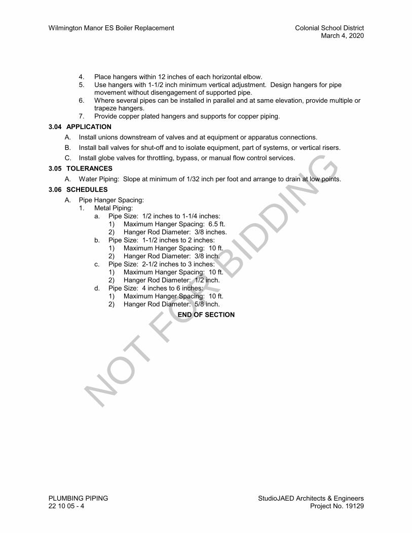
Wilmington Manor ES Boiler Replacement Colonial School District March 4, 2020
PLUMBING PIPING StudioJAED Architects & Engineers22 10 05 - 4 Project No. 19129
4. Place hangers within 12 inches of each horizontal elbow.5. Use hangers with 1-1/2 inch minimum vertical adjustment. Design hangers for pipe
movement without disengagement of supported pipe.6. Where several pipes can be installed in parallel and at same elevation, provide multiple or
trapeze hangers.7. Provide copper plated hangers and supports for copper piping.
3.04 APPLICATIONA. Install unions downstream of valves and at equipment or apparatus connections.B. Install ball valves for shut-off and to isolate equipment, part of systems, or vertical risers.C. Install globe valves for throttling, bypass, or manual flow control services.
3.05 TOLERANCESA. Water Piping: Slope at minimum of 1/32 inch per foot and arrange to drain at low points.
3.06 SCHEDULESA. Pipe Hanger Spacing:
1. Metal Piping:a. Pipe Size: 1/2 inches to 1-1/4 inches:
1) Maximum Hanger Spacing: 6.5 ft.2) Hanger Rod Diameter: 3/8 inches.
b. Pipe Size: 1-1/2 inches to 2 inches:1) Maximum Hanger Spacing: 10 ft.2) Hanger Rod Diameter: 3/8 inch.
c. Pipe Size: 2-1/2 inches to 3 inches:1) Maximum Hanger Spacing: 10 ft.2) Hanger Rod Diameter: 1/2 inch.
d. Pipe Size: 4 inches to 6 inches:1) Maximum Hanger Spacing: 10 ft.2) Hanger Rod Diameter: 5/8 inch.
END OF SECTION
NOT FOR B
IDDIN
G
Colonial School District Wilmington Manor ES Boiler ReplacementMarch 4, 2020
StudioJAED Architects & EngineersProject No. 19129
PLUMBING EQUIPMENT22 30 00 - 1
SECTION 22 30 00PLUMBING EQUIPMENT
PART 1 GENERAL1.01 SECTION INCLUDES
A. Water Heaters:1. Commercial gas fired.
1.02 RELATED REQUIREMENTSA. Section 22 05 48 - Vibration and Seismic Controls for Plumbing Piping and Equipment.B. Section 26 27 17 - Equipment Wiring: Electrical characteristics and wiring connections.
1.03 REFERENCE STANDARDSA. ANSI Z21.10.1 - Gas Water Heaters - Volume I - Storage Water Heaters with Input Ratings of
75,000 Btu per Hour or Less.B. CSA P.3 - Testing Method for Measuring Energy Consumption and Determining Efficiencies of
Gas-Fired Storage Water Heaters.C. ICC (IPC) - International Plumbing Code.
1.04 SUBMITTALSA. See Section 01 30 00 - Administrative Requirements, for submittals procedures.B. Product Data:
1. Provide dimension drawings of water heaters indicating components and connections toother equipment and piping.
2. Indicate pump type, capacity, power requirements.3. Provide certified pump curves showing pump performance characteristics with pump and
system operating point plotted. Include NPSH curve when applicable.4. Provide electrical characteristics and connection requirements.
C. Warranty Documentation: Submit manufacturer warranty and ensure that forms have beencompleted in Owner's name and registered with manufacturer.
1.05 QUALITY ASSURANCEA. Manufacturer Qualifications: Company specializing in manufacturing the type of products
specified in this section, with minimum three years of documented experience.B. Certifications:
1. Water Heaters: NSF approved.2. Gas Water Heaters: Certified by CSA International to ANSI Z21.10.1, as applicable, in
addition to requirements specified elsewhere.1.06 DELIVERY, STORAGE, AND HANDLING
A. Provide temporary inlet and outlet caps. Maintain caps in place until installation.1.07 WARRANTY
A. See Section 01 78 00 - Closeout Submittals, for additional warranty requirements.PART 2 PRODUCTS2.01 WATER HEATERS
A. Manufacturers:1. A.O. Smith Water Products Co; ______: www.hotwater.com/#sle.2. PVI; www.pvi.com3. Bradford White; www.bradfordwhite.com
NOT FOR B
IDDIN
G

Wilmington Manor ES Boiler Replacement Colonial School DistrictMarch 4, 2020
PLUMBING EQUIPMENT StudioJAED Architects & Engineers22 30 00 - 2 Project No. 19129
B. Commercial Gas Fired:1. Type: Automatic, natural gas-fired, vertical storage.2. Performance:3. Tank: Glass lined welded steel ASME labeled; multiple flue passages, 4 inch diameter
inspection port, thermally insulated with minimum 2 inches glass fiber, encased incorrosion-resistant steel jacket; baked-on enamel finish; floor shield and legs.
4. Accessories:a. Water Connections: Brass.b. Dip Tube: Brass.c. Drain valve.d. Anode: Magnesium.
5. Certified For The Following Applications:PART 3 EXECUTION3.01 INSTALLATION
A. Install plumbing equipment in accordance with manufacturer's instructions, as required by code,and complying with conditions of certification, if any.
B. Coordinate with plumbing piping and related fuel piping work to achieve operating system.END OF SECTION
NOT FOR B
IDDIN
G

Colonial School District Wilmington Manor ES Boiler ReplacementMarch 4, 2020
StudioJAED Architects & EngineersProject No. 19129
EXPANSION FITTINGS ANDLOOPS FOR HVAC PIPING
23 05 16 - 1
SECTION 23 05 16EXPANSION FITTINGS AND LOOPS FOR HVAC PIPING
PART 1 GENERAL1.01 SECTION INCLUDES
A. Flexible pipe connectors.B. Expansion joints and compensators.C. Pipe loops, offsets, and swing joints.
1.02 RELATED REQUIREMENTSA. Section 23 21 13 - Hydronic Piping.
1.03 REFERENCE STANDARDSA. ASTM A269/A269M - Standard Specification for Seamless and Welded Austenitic Stainless
Steel Tubing for General Service.B. EJMA (STDS) - EJMA Standards.
1.04 SUBMITTALSA. Product Data:
1. Flexible Pipe Connectors: Indicate maximum temperature and pressure rating,face-to-face length, live length, hose wall thickness, hose convolutions per foot and perassembly, fundamental frequency of assembly, braid structure, and total number of wiresin braid.
2. Expansion Joints: Indicate maximum temperature and pressure rating, and maximumexpansion compensation.
B. Design Data: Indicate selection calculations.C. Manufacturer's Instructions: Indicate manufacturer's installation instructions, special
procedures, and external controls.D. Project Record Documents: Record installed locations of flexible pipe connectors, expansion
joints, anchors, and guides.E. Maintenance Data: Include adjustment instructions.
1.05 REGULATORY REQUIREMENTSA. Conform to UL requirements.
1.06 EXTRA MATERIALSA. Supply two sets of packing for each packed expansion joint.
PART 2 PRODUCTS2.01 FLEXIBLE PIPE CONNECTORS - STEEL PIPING
A. Manufacturers:1. Mercer Rubber Company: www.mercer-rubber.com/#sle.2. Metraflex Company: www.metraflex.com.
B. Inner Hose: Carbon Steel.C. Exterior Sleeve: Single braided, stainless steel or bronze.D. Pressure Rating: 125 psi and 450 degrees F.E. Joint: As specified for pipe joints.F. Size: Use pipe sized units.
NOT FOR B
IDDIN
G
Wilmington Manor ES Boiler Replacement Colonial School DistrictMarch 4, 2020
EXPANSION FITTINGS AND LOOPS FOR HVAC PIPINGStudioJAED Architects & Engineers23 05 16 - 2 Project No. 19129
G. Maximum offset: 3/4 inch on each side of installed center line.2.02 FLEXIBLE PIPE CONNECTORS - COPPER PIPING
A. Manufacturer:1. Mercer Rubber Company: www.mercer-rubber.com/#sle.2. Metraflex Company: www.metraflex.com/#sle.
B. Inner Hose: Bronze.C. Exterior Sleeve: Braided bronze.D. Pressure Rating: 125 psi and 450 degrees F.E. Joint: As specified for pipe joints.F. Size: Use pipe sized units.G. Maximum offset: 3/4 inch on each side of installed center line.H. Application: Copper piping.
2.03 EXPANSION JOINTS - STAINLESS STEEL BELLOWS TYPEA. Manufacturers:
1. Mercer Rubber Company: www.mercer-rubber.com/#sle.2. Metraflex Company: www.metraflex.com/#sle.
B. Pressure Rating: 125 psi and 400 degrees F.C. Maximum Compression: 1-3/4 inches.D. Maximum Extension: 1/4 inch.E. Joint: As specified for pipe joints.F. Size: Use pipe sized units.G. Application: Steel piping 3 inches and under.
2.04 EXPANSION JOINTS - EXTERNAL RING CONTROLLED STAINLESS STEEL BELLOWS TYPEA. Manufacturers:
1. Mercer Rubber Company: www.mercer-rubber.com/#sle.2. Metraflex Company: www.metraflex.com/#sle.
B. Pressure Rating: 125 psi and 400 degrees F.C. Maximum Compression: 15/16 inch.D. Maximum Extension: 5/16 inch.E. Maximum Offset: 1/8 inch.F. Joint: Flanged.G. Size: Use pipe sized units.H. Accessories: Internal flow liner.I. Application: Steel piping over 2 inches.
2.05 EXPANSION JOINTS - SINGLE SPHERE, ELBOW OR FLEXIBLE COMPENSATORA. Manufacturers:
1. Mercer Rubber Company: www.mercer-rubber.com/#sle.2. Metraflex Company: www.metraflex.com/#sle.
B. Body: Teflon.C. Pressure Rating, Sizes 3/4 Inch to 2 Inch: 150 psi and 210 degrees F.
NOT FOR B
IDDIN
G

Colonial School District Wilmington Manor ES Boiler ReplacementMarch 4, 2020
StudioJAED Architects & EngineersProject No. 19129
EXPANSION FITTINGS ANDLOOPS FOR HVAC PIPING
23 05 16 - 3
D. Pressure Rating, Sizes 1-1/2 Inch to 12 Inch: 150 psi and 250 degrees F.E. Pressure Rating, Sizes 14 Inch to 24 Inch: 105 psi and 250 degrees F.F. Maximum Compression: 3/4 inch.G. Maximum Elongation: 1/2 inch.H. Maximum Offset: 1/2 inch.I. Maximum Angular Movement: 15 degrees.J. Joint: Tapped steel flanges.K. Size: Use pipe sized units.L. Accessories: Control rods.M. Application: Steel piping 2 inches and over.
2.06 EXPANSION JOINTS - TWO-PLY BRONZE BELLOWS TYPEA. Manufacturers:
1. Mercer Rubber Company: www.mercer-rubber.com/#sle.2. Metraflex Company: www.metraflex.com/#sle.
B. Construction: Bronze with anti-torque device, limit stops, internal guides.C. Pressure Rating: 125 psi and 400 degrees F.D. Maximum Compression: 1-3/4 inches.E. Maximum Extension: 1/4 inch.F. Joint: As specified for pipe joints.G. Size: Use pipe sized units.H. Application: Copper piping.
2.07 EXPANSION JOINTS - LOW PRESSURE COMPENSATOR WITH TWO-PLY BRONZEBELLOWSA. Manufacturers:
1. Mercer Rubber Company: www.mercer-rubber.com/#sle.2. Metraflex Company: www.metraflex.com/#sle.
B. Working Pressure: 75 psi.C. Maximum Temperatures: 250 degrees F.D. Maximum Compression: 1/2 inch.E. Maximum Extension: 5/32 inch.F. Joint: Soldered.G. Size: Use pipe sized units.H. Application: Copper or steel piping 3 inches and under.
2.08 EXPANSION JOINTS - STEEL WITH PACKED SLIDING SLEEVEA. Working Pressure and Temperature: Class 150.B. Joint: As specified for pipe joints.C. Size: Use pipe sized units.D. Application: Steel piping 2 inches and over.
2.09 EXPANSION JOINTS - COPPER WITH PACKED SLIDING SLEEVEA. Working Pressure: 125 psi.
NOT FOR B
IDDIN
G

Wilmington Manor ES Boiler Replacement Colonial School DistrictMarch 4, 2020
EXPANSION FITTINGS AND LOOPS FOR HVAC PIPINGStudioJAED Architects & Engineers23 05 16 - 4 Project No. 19129
B. Maximum Temperature: 250 degrees F.C. Joint: As specified for pipe joints.D. Size: Use pipe sized units.E. Application: Copper or steel piping 2 inches and over.
2.10 ACCESSORIESA. Stainless Steel Pipe: ASTM A269.B. Pipe Alignment Guides:
1. Two piece welded steel with enamel paint, bolted, with spider to fit standard pipe, framewith four mounting holes, clearance for minimum 1 inch thick insulation, minimum 3 inchestravel.
C. Swivel Joints:1. Fabricated steel body, double ball bearing race, field lubricated, with rubber (Buna-N)
o-ring seals.PART 3 EXECUTION3.01 INSTALLATION
A. Install in accordance with manufacturer's instructions.B. Install in accordance with EJMA (Expansion Joint Manufacturers Association) Standards.C. Install flexible pipe connectors on pipes connected to vibration isolated equipment. Provide line
size flexible connectors.D. Install flexible connectors at right angles to displacement. Install one end immediately adjacent
to isolated equipment and anchor other end. Install in horizontal plane unless indicatedotherwise.
E. Anchor pipe to building structure where indicated. Provide pipe guides so movement is directedalong axis of pipe only. Erect piping such that strain and weight is not on cast connections orapparatus.
F. Provide support and equipment required to control expansion and contraction of piping. Provideloops, pipe offsets, and swing joints, or expansion joints where required.
G. Substitute grooved piping for vibration isolated equipment instead of flexible connectors. Grooved piping need not be anchored.
END OF SECTION
NOT FOR B
IDDIN
G
Colonial School District Wilmington Manor ES Boiler ReplacementMarch 4, 2020
StudioJAED Architects & EngineersProject No. 19129
METERS AND GAGES FORHVAC PIPING
23 05 19 - 1
SECTION 23 05 19METERS AND GAGES FOR HVAC PIPING
PART 1 GENERAL1.01 SECTION INCLUDES
A. Pressure gage taps.B. Thermometers and thermometer wells.
1.02 REFERENCE STANDARDSA. ASME B40.100 - Pressure Gauges and Gauge Attachments.B. ASTM E1 - Standard Specification for ASTM Liquid-in-Glass Thermometers.C. ASTM E77 - Standard Test Method for Inspection and Verification of Thermometers.D. UL 393 - Indicating Pressure Gauges for Fire-Protection Service.
1.03 SUBMITTALSA. See Section 01 33 00 - Administrative Requirements, for submittal procedures.B. Product Data: Provide list that indicates use, operating range, total range and location for
manufactured components.C. Samples: Submit one of each type of instrument specified.D. Project Record Documents: Record actual locations of components and instrumentation.E. Operation and Maintenance Data: pressure gages, thermometers, static pressure gages.
1.04 FIELD CONDITIONSA. Do not install instrumentation when areas are under construction, except for required rough-in,
taps, supports and test plugs.PART 2 PRODUCTS2.01 PRESSURE GAGES
A. Manufacturers:1. Dwyer Instruments, Inc: www.dwyer-inst.com/#sle.2. Moeller Instrument Co., Inc: www.moellerinstrument.com/#sle.3. Omega Engineering, Inc: www.omega.com/#sle.
B. Pressure Gages: ASME B40.100, UL 393 drawn steel case, phosphor bronze bourdon tube,rotary brass movement, brass socket, with front recalibration adjustment, black scale on whitebackground.1. Case: Steel with brass bourdon tube.2. Size: 4-1/2 inch diameter.3. Mid-Scale Accuracy: One percent.4. Scale: Psi and KPa.
2.02 PRESSURE GAGE TAPPINGSA. Gage Cock: Tee or lever handle, brass for maximum 150 psi.B. Needle Valve: Brass or stainless steel 1/4 inch NPT for minimum 150 psi.C. Pulsation Damper: Pressure snubber, brass with 1/4 inch connections.D. Syphon: Brass, Stainless Steel or Bronze 1/4 inch angle or straight pattern.
2.03 STEM TYPE THERMOMETERSA. Manufacturers:
1. Dwyer Instruments, Inc: www.dwyer-inst.com/#sle.
NOT FOR B
IDDIN
G

Wilmington Manor ES Boiler Replacement Colonial School DistrictMarch 4, 2020
METERS AND GAGES FOR HVAC PIPING StudioJAED Architects & Engineers23 05 19 - 2 Project No. 19129
2. Omega Engineering, Inc: www.omega.com/#sle.3. Weksler Glass Thermometer Corp: www.wekslerglass.com/#sle.4. Substitutions: See Section 01 60 00 - Product Requirements.
B. Thermometers - Fixed Mounting: Red- or blue-appearing non-toxic liquid in glass; ASTM E1; lens front tube, cast aluminum case with enamel finish.1. Size: 7 inch scale.2. Window: Clear Lexan.3. Stem: 3/4 inch brass.4. Accuracy: 2 percent, per ASTM E77.5. Calibration: Degrees F and Degrees C.
C. Thermometers - Adjustable Angle: Red- or blue-appearing non-toxic liquid in glass; ASTM E1;lens front tube, cast aluminum case with enamel finish, cast aluminum adjustable joint withpositive locking device; adjustable 360 degrees in horizontal plane, 180 degrees in verticalplane.1. Size: 7 inch scale.2. Window: Clear Lexan.3. Stem: 3/4 inch NPT brass.4. Accuracy: 2 percent, per ASTM E77.5. Calibration: Degrees F and Degrees C.
2.04 DIAL THERMOMETERSA. Manufacturers:
1. Dwyer Instruments, Inc: www.dwyer-inst.com/#sle.2. Omega Engineering, Inc: www.omega.com/#sle.3. Weksler Glass Thermometer Corp: www.wekslerglass.com/#sle.4. Substitutions: See Section 01 60 00 - Product Requirements.
B. Thermometers - Fixed Mounting: Dial type bimetallic actuated; ASTM E1; stainless steel case,silicone fluid damping, white with black markings and black pointer, hermetically sealed lens,stainless steel stem.1. Size: 2 inch diameter dial.2. Lens: Clear Lexan.3. Accuracy: 1 percent.4. Calibration: Degrees F and Degrees C.
C. Thermometer: ASTM E1, stainless steel case, adjustable angle with front recalibration,bimetallic helix actuated with silicone fluid damping, white with black markings and black pointerhermetically sealed lens, stainless steel stem.1. Size: 3 inch diameter dial.2. Lens: Clear Lexan.3. Accuracy: 1 percent.4. Calibration: Degrees F and Degrees C.
D. Thermometers: Dial type vapor or liquid actuated; ASTM E1; stainless steel case, with brass orcopper bulb, copper or bronze braided capillary, white with black markings and black pointer,glass lens.1. Size: 2-1/2 inch diameter dial.2. Lens: Clear Lexan.3. Length of Capillary: Minimum 5 feet.4. Accuracy: 2 percent.5. Calibration: Degrees F and Degrees C.
NOT FOR B
IDDIN
G

Colonial School District Wilmington Manor ES Boiler ReplacementMarch 4, 2020
StudioJAED Architects & EngineersProject No. 19129
METERS AND GAGES FORHVAC PIPING
23 05 19 - 3
2.05 THERMOMETER SUPPORTSA. Socket: Brass separable sockets for thermometer stems with or without extensions as
required, and with cap and chain.B. Flange: 3 inch outside diameter reversible flange, designed to fasten to sheet metal air ducts,
with brass perforated stem.2.06 TEST PLUGS
A. Test Plug: 1/4 inch or 1/2 inch brass or stainless steel fitting and cap for receiving 1/8 inchoutside diameter pressure or temperature probe with neoprene core for temperatures up to 200degrees F.
B. Test Plug: 1/4 inch or 1/2 inch brass or stainless steel fitting and cap for receiving 1/8 inchoutside diameter pressure or temperature probe with Nordel core for temperatures up to 350degrees F.
C. Test Plug: 1/4 inch or 1/2 inch brass or stainless steel fitting and cap for receiving 1/8 inchoutside diameter pressure or temperature probe with Viton core for temperatures up to 400degrees F.
D. Test Kit: Carrying case, internally padded and fitted containing one 2-1/2 inch diameterpressure gages, one gage adapters with 1/8 inch probes, two 1-1/2 inch dial thermometers.
PART 3 EXECUTION3.01 INSTALLATION
A. Install in accordance with manufacturer's instructions.B. Provide one pressure gage per pump, installing taps before strainers and on suction and
discharge of pump. Pipe to gage.C. Install pressure gages with pulsation dampers. Provide gage cock to isolate each gage.
Extend nipples to allow clearance from insulation.D. Install thermometers in piping systems in sockets in short couplings. Enlarge pipes smaller
than 2-1/2 inch for installation of thermometer sockets. Ensure sockets allow clearance frominsulation.
E. Install thermometer sockets adjacent to controls systems theremostat, transmitter, or sensorsockets. Where thermometers are provided on local panels, duct or pipe mountedthermometers are provided at local panels, duct or pipe mounted thermometers are notrequired.
F. Coil and conceal excess capillary on remote element instruments.G. Provide instruments with scale ranges selected according to service with largest appropriate
scale.H. Install gages and thermometers in locations where they are easily read from normal operating
level. Install vertical to 45 degrees off vertical.I. Adjust gages and thermometers to final angle, clean windows and lenses, and calibrate to zero.J. Locate test plugs adjacent thermometers and thermometer sockets, adjacent to pressure gages
and pressure gage taps, adjacent to control device sockets and where indicated.3.02 SCHEDULE
A. Pressure Gages, Location and Scale Range:1. Pumps, 0 to 225 psi.2. Expansion tanks, 0 to 225 psi.3. Pressure tanks, 0 to 225 psi.
NOT FOR B
IDDIN
G

Wilmington Manor ES Boiler Replacement Colonial School DistrictMarch 4, 2020
METERS AND GAGES FOR HVAC PIPING StudioJAED Architects & Engineers23 05 19 - 4 Project No. 19129
B. Pressure Gage Tappings, Location:1. Control valves 3/4 inch & larger - inlets and outlets.2. Boiler - inlets and outlets.
C. Stem Type Thermometers, Location and Scale Range:1. Headers to central equipment, 0 to 220 degrees F.2. Boilers - inlets and outlets, 0 to 220 degrees F.
D. Thermometer Sockets, Location:1. Control valves 1 inch & larger - inlets and outlets.
END OF SECTION
NOT FOR B
IDDIN
G

Colonial School District Wilmington Manor ES Boiler ReplacementMarch 4, 2020
StudioJAED Architects & EngineersProject No. 19129
IDENTIFICATION FOR HVACPIPING AND EQUIPMENT
23 05 53 - 1
SECTION 23 05 53IDENTIFICATION FOR HVAC PIPING AND EQUIPMENT
PART 1 GENERAL1.01 SECTION INCLUDES
A. Nameplates.B. Tags.C. Pipe Markers.
1.02 REFERENCE STANDARDSA. ASME A13.1 - Scheme for the Identification of Piping Systems.
1.03 SUBMITTALSA. See Section 01 30 00 - Administrative Requirements, for submittal procedures.B. List: Submit list of wording, symbols, letter size, and color coding for mechanical identification.C. Chart and Schedule: Submit valve chart and schedule, including valve tag number, location,
function, and valve manufacturer's name and model number.D. Product Data: Provide manufacturers catalog literature for each product required.E. Samples: Submit two labels, tags and pipe markers.F. Manufacturer's Installation Instructions: Indicate special procedures, and installation.G. Project Record Documents: Record actual locations of tagged valves.
PART 2 PRODUCTS2.01 IDENTIFICATION APPLICATIONS
A. Automatic Controls: Tags. Key to control schematic.B. Control Panels: Nameplates.C. Instrumentation: Tags.D. Major Control Components: Nameplates.E. Piping: Pipe markers.F. Pumps: Nameplates.G. Thermostats: Nameplates.H. Valves: Tags.
2.02 MANUFACTURERSA. Brady Corporation: www.bradycorp.com.B. Champion America, Inc: www.Champion-America.com.C. Seton Identification Products: www.seton.com/aec.D. Substitutions: See Section 01 60 00 - Product Requirements.
2.03 NAMEPLATESA. Description: Laminated three-layer plastic with engraved letters.
1. Letter Color: White.2. Letter Height: 1/4 inch.3. Background Color: Green.
NOT FOR B
IDDIN
G
Wilmington Manor ES Boiler Replacement Colonial School DistrictMarch 4, 2020
IDENTIFICATION FOR HVAC PIPING AND EQUIPMENTStudioJAED Architects & Engineers23 05 53 - 2 Project No. 19129
2.04 TAGSA. Plastic Tags: Laminated three-layer plastic with engraved white letters on green contrasting
background color. Tag size minimum 1-1/2 inch diameter.B. Metal Tags: Brass with stamped letters; tag size minimum 1-1/2 inch diameter with smooth
edges.C. Valve Tag Chart: Typewritten letter size list in anodized aluminum frame.
2.05 PIPE MARKERSA. Color: Conform to ASME A13.1.B. Plastic Pipe Markers: Factory fabricated, flexible, semi- rigid plastic, preformed to fit around
pipe or pipe covering; minimum information indicating flow direction arrow and identification offluid being conveyed.
C. Plastic Tape Pipe Markers: Flexible, vinyl film tape with pressure sensitive adhesive backingand printed markings.
D. Underground Plastic Pipe Markers: Bright colored continuously printed plastic ribbon tape,minimum 6 inches wide by 4 mil thick, manufactured for direct burial service.
PART 3 EXECUTION3.01 PREPARATION
A. Degrease and clean surfaces to receive adhesive for identification materials.B. Prepare surfaces in accordance with Section 09 90 00 for stencil painting.
3.02 INSTALLATIONA. Install nameplates with corrosive-resistant mechanical fasteners, or adhesive. Apply with
sufficient adhesive to ensure permanent adhesion and seal with clear lacquer.B. Install tags with corrosion resistant chain.C. Apply stencil painting in accordance with Section 09 90 00.D. Install plastic pipe markers in accordance with manufacturer's instructions.E. Install plastic tape pipe markers complete around pipe in accordance with manufacturer's
instructions.F. Install underground plastic pipe markers 6 to 8 inches below finished grade, directly above
buried pipe.G. Use tags on piping 3/4 inch diameter and smaller.
1. Identify service, flow direction, and pressure.2. Install in clear view and align with axis of piping.3. Locate identification not to exceed 20 feet on straight runs including risers and drops,
adjacent to each valve and Tee, at each side of penetration of structure or enclosure, andat each obstruction.
H. Identify air handling units, pumps, heat transfer equipment, tanks, and water treatment deviceswith plastic nameplates. Small devices, such as in-line pumps, may be identified with tags.
I. Identify control panels and major control components outside panels with plastic nameplates.J. Identify thermostats relating to terminal boxes or valves with nameplates.K. Identify valves in main and branch piping with tags.L. Identify air terminal units and radiator valves with numbered tags.M. Tag automatic controls, instruments, and relays. Key to control schematic.
NOT FOR B
IDDIN
G

Colonial School District Wilmington Manor ES Boiler ReplacementMarch 4, 2020
StudioJAED Architects & EngineersProject No. 19129
IDENTIFICATION FOR HVACPIPING AND EQUIPMENT
23 05 53 - 3
N. Identify piping, concealed or exposed, with plastic pipe markers. Use tags on piping 3/4 inchdiameter and smaller. Identify service, flow direction, and pressure. Install in clear view andalign with axis of piping. Locate identification not to exceed 20 feet on straight runs includingrisers and drops, adjacent to each valve and Tee, at each side of penetration of structure orenclosure, and at each obstruction.
3.03 UNIT TAG SCHEDULEA. Equipment Type: Boiler (B)
1. Identification: Nameplate (B-X) where X = Unit number. Include manufacturer, modelnumber, serial number, date of manufacturer start-up, date of manufacture, voltage,frequency, phase
2. Background:a. Size: As needed to contain informationb. Color: Yellow
3. Lettering:a. Size: 1/4 inch highb. Color: Black
4. Placement: As directed by Architect/EngineerB. Equipment Type: Pumps (P)
1. Identification: Tag (P-X) where X = Pump number. Include manufacturer, model number,serial number, date of manufacturer start-up, date of manufacture, voltage, frequncy,phase, GPM, Design Head Pressure (FT H2O)
2. Background:a. Size: As needed to contain informationb. Color: Yellow
3. Lettering:a. Size: 1/4 inch highb. Color: White
4. Placement: As directed by Architect/EngineerEND OF SECTION
NOT FOR B
IDDIN
G

NOT FOR B
IDDIN
G
Colonial School District Wilmington Manor ES Boiler ReplacementMarch 4, 2020
StudioJAED Architects & EngineersProject No. 19129
TESTING, ADJUSTING, ANDBALANCING FOR HVAC
23 05 93 - 1
SECTION 23 05 93TESTING, ADJUSTING, AND BALANCING FOR HVAC
PART 1 GENERAL1.01 SECTION INCLUDES
A. Testing, adjustment, and balancing of hydronic as applicable systems.B. Measurement of final operating condition of HVAC systems.C. Sound measurement of equipment operating conditions.D. Vibration measurement of equipment operating conditions.
1.02 REFERENCE STANDARDSA. SMACNA (TAB) - HVAC Systems Testing, Adjusting and Balancing.
1.03 SUBMITTALS A. See Section 01 30 00 - Administrative Requirements, for submittal procedures.B. Installer Qualifications: Submit name of adjusting and balancing agency and TAB supervisor for
approval within 30 days after award of Contract.C. TAB Plan: Submit a written plan indicating the testing, adjusting, and balancing standard to be
followed and the specific approach for each system and component.1. Submit to the HVAC controls contractor.2. Submit six weeks prior to starting the testing, adjusting, and balancing work.3. Include certification that the plan developer has reviewed the contract documents, the
equipment and systems, and the control system with the Architect and other installers tosufficiently understand the design intent for each system.
4. Include at least the following in the plan:a. Preface: An explanation of the intended use of the control system.b. List of all air flow, water flow, sound level, system capacity and efficiency
measurements to be performed and a description of specific test procedures,parameters, formulas to be used.
c. Copy of field checkout sheets and logs to be used, listing each piece of equipment tobe tested, adjusted and balanced with the data cells to be gathered for each.
d. Identification and types of measurement instruments to be used and their most recentcalibration date.
e. Discussion of what notations and markings will be made on the duct and pipingdrawings during the process.
f. Final test report forms to be used.g. Detailed step-by-step procedures for TAB work for each system and issue, including:
1) Branch/submain proportioning.2) Total flow calculations.3) Rechecking.4) Diversity issues.
h. Expected problems and solutions, etc.i. Details of how TOTAL flow will be determined; for example:
1) Water: Pump curves, circuit setter, flow station, ultrasonic, etc.j. Specific procedures that will ensure that both air and water side are operating at the
lowest possible pressures and methods to verify this.k. Confirmation of understanding of the outside air ventilation criteria under all
conditions.l. Method of verifying and setting minimum outside air flow rate will be verified and set
and for what level (total building, zone, etc.).
NOT FOR B
IDDIN
G
Wilmington Manor ES Boiler Replacement Colonial School DistrictMarch 4, 2020
TESTING, ADJUSTING, AND BALANCING FOR HVACStudioJAED Architects & Engineers23 05 93 - 2 Project No. 19129
m. Method of checking building static and exhaust fan and/or relief damper capacity.n. Proposed selection points for sound measurements and sound measurement
methods.o. Methods for making coil or other system plant capacity measurements, if specified.p. Time schedule for TAB work to be done in phases (by floor, etc.).q. Description of TAB work for areas to be built out later, if any.r. Time schedule for deferred or seasonal TAB work, if specified.s. False loading of systems to complete TAB work, if specified.t. Exhaust fan balancing and capacity verifications, including any required room
pressure differentials.u. Interstitial cavity differential pressure measurements and calculations, if specified.v. Procedures for field technician logs of discrepancies, deficient or uncompleted work
by others, contract interpretation requests and lists of completed tests (scope andfrequency).
w. Procedures for formal progress reports, including scope and frequency.x. Procedures for formal deficiency reports, including scope, frequency and distribution.
D. Field Logs: Submit at least twice a week to Studio JAED; Construction Manager and HVACControls Contractor.
E. Control System Coordination Reports: Communicate in writing to the controls installer allsetpoint and parameter changes made or problems and discrepancies identified during TABthat affect, or could affect, the control system setup and operation.
F. Progress Reports.G. Final Report: Indicate deficiencies in systems that would prevent proper testing, adjusting, and
balancing of systems and equipment to achieve specified performance.1. Submit to the Construction Manager; Studio JAED and HVAC Controls Contractor within
two weeks after completion of testing, adjusting, and balancing.2. Revise TAB plan to reflect actual procedures and submit as part of final report.3. Submit draft copies of report for review prior to final acceptance of Project. Provide final
copies for Architect and for inclusion in operating and maintenance manuals.4. Provide reports in hard cover letter size 3-ring binder manuals, complete with index page
and indexing tabs, with cover identification at front and side. Include set of reduceddrawings with air outlets and equipment identified to correspond with data sheets, andindicating thermostat locations.
5. Include actual instrument list, with manufacturer name, serial number, and date ofcalibration.
6. Form of Test Reports: Where the TAB standard being followed recommends a reportformat use that; otherwise, follow ASHRAE Std 111.
7. Units of Measure: Report data in I-P (inch-pound) units only.8. Include the following on the title page of each report:
a. Name of Testing, Adjusting, and Balancing Agency.b. Address of Testing, Adjusting, and Balancing Agency.c. Telephone number of Testing, Adjusting, and Balancing Agency.d. Project name.e. Project location.f. Project Engineer.g. Project Contractor.h. Project altitude.i. Report date.
NOT FOR B
IDDIN
G

Colonial School District Wilmington Manor ES Boiler ReplacementMarch 4, 2020
StudioJAED Architects & EngineersProject No. 19129
TESTING, ADJUSTING, ANDBALANCING FOR HVAC
23 05 93 - 3
H. Project Record Documents: Record actual locations of flow measuring stations and balancingvalves and rough setting.
PART 2 PRODUCTS - NOT USEDPART 3 EXECUTION3.01 GENERAL REQUIREMENTS
A. Perform total system balance in accordance with one of the following:1. AABC MN-1, AABC National Standards for Total System Balance.2. NEBB Procedural Standards for Testing Adjusting Balancing of Environmental Systems.3. SMACNA (TAB).4. Maintain at least one copy of the standard to be used at project site at all times.
B. Begin work after completion of systems to be tested, adjusted, or balanced and complete workprior to Substantial Completion of the project.
C. Where HVAC systems and/or components interface with life safety systems, including fire andsmoke detection, alarm, and control, coordinate scheduling and testing and inspectionprocedures with the authorities having jurisdiction.
D. TAB Agency Qualifications:1. Company specializing in the testing, adjusting, and balancing of systems specified in this
section.2. Having minimum of three years documented experience.3. Certified by one of the following:
a. AABC, Associated Air Balance Council: www.aabchq.com; upon completion submitAABC National Performance Guaranty.
b. NEBB, National Environmental Balancing Bureau: www.nebb.org/#sle.c. TABB, The Testing, Adjusting, and Balancing Bureau of National Energy
Management Institute: www.tabbcertified.org/#sle.E. TAB Supervisor Qualifications: Professional Engineer licensed in the State in which the Project
is located.3.02 EXAMINATION
A. Verify that systems are complete and operable before commencing work. Ensure the followingconditions:1. Systems are started and operating in a safe and normal condition.2. Temperature control systems are installed complete and operable.3. Proper thermal overload protection is in place for electrical equipment.4. Final filters are clean and in place. If required, install temporary media in addition to final
filters.5. Access doors are closed and duct end caps are in place.6. Hydronic systems are flushed, filled, and vented.7. Pumps are rotating correctly.8. Proper strainer baskets are clean and in place.9. Service and balance valves are open.
B. Submit field reports. Report defects and deficiencies that will or could prevent proper systembalance.
C. Beginning of work means acceptance of existing conditions.3.03 PREPARATION
A. Hold a pre-balancing meeting at least one week prior to starting TAB work.1. Require attendance by all installers whose work will be tested, adjusted, or balanced.
NOT FOR B
IDDIN
G

Wilmington Manor ES Boiler Replacement Colonial School DistrictMarch 4, 2020
TESTING, ADJUSTING, AND BALANCING FOR HVACStudioJAED Architects & Engineers23 05 93 - 4 Project No. 19129
B. Provide instruments required for testing, adjusting, and balancing operations. Make instrumentsavailable to Architect to facilitate spot checks during testing.
C. Provide additional balancing devices as required.3.04 ADJUSTMENT TOLERANCES
A. Hydronic Systems: Adjust to within plus or minus 10 percent of design.3.05 RECORDING AND ADJUSTING
A. Field Logs: Maintain written logs including:1. Running log of events and issues.2. Discrepancies, deficient or uncompleted work by others.3. Contract interpretation requests.4. Lists of completed tests.
B. Ensure recorded data represents actual measured or observed conditions.C. Permanently mark settings of valves, dampers, and other adjustment devices allowing settings
to be restored. Set and lock memory stops.D. Mark on drawings the locations where traverse and other critical measurements were taken and
cross reference the location in the final report.E. After adjustment, take measurements to verify balance has not been disrupted or that such
disruption has been rectified.F. Leave systems in proper working order, replacing belt guards, closing access doors, closing
doors to electrical switch boxes, and restoring thermostats to specified settings.G. At final inspection, recheck random selections of data recorded in report. Recheck points or
areas as selected and witnessed by the Owner.H. Check and adjust systems approximately six months after final acceptance and submit report.
3.06 WATER SYSTEM PROCEDUREA. Adjust water systems to provide required or design quantities.B. Use calibrated Venturi tubes, orifices, or other metered fittings and pressure gauges to
determine flow rates for system balance. Where flow metering devices are not installed, baseflow balance on temperature difference across various heat transfer elements in the system.
C. Adjust systems to provide specified pressure drops and flows through heat transfer elementsprior to thermal testing. Perform balancing by measurement of temperature differential inconjunction with air balancing.
D. Effect system balance with automatic control valves fully open to heat transfer elements.E. Effect adjustment of water distribution systems by means of balancing cocks, valves, and
fittings. Do not use service or shut-off valves for balancing unless indexed for balance point.F. Where available pump capacity is less than total flow requirements or individual system parts,
full flow in one part may be simulated by temporary restriction of flow to other parts.3.07 SCOPE
A. Test, adjust, and balance the following:1. Plumbing Pumps.2. HVAC Pumps.3. Packaged Steel Fire Tube Boilers.
3.08 MINIMUM DATA TO BE REPORTEDA. Electric Motors:
1. Manufacturer
NOT FOR B
IDDIN
G

Colonial School District Wilmington Manor ES Boiler ReplacementMarch 4, 2020
StudioJAED Architects & EngineersProject No. 19129
TESTING, ADJUSTING, ANDBALANCING FOR HVAC
23 05 93 - 5
2. Model/Frame 3. HP/BHP 4. Phase, voltage, amperage; nameplate, actual, no load5. RPM 6. Service factor7. Starter size, rating, heater elements8. Sheave Make/Size/Bore
B. V-Belt Drives:1. Identification/location 2. Required driven RPM3. Driven sheave, diameter and RPM4. Belt, size and quantity5. Motor sheave diameter and RPM6. Center to center distance, maximum, minimum, and actual
C. Pumps:1. Identification/number 2. Manufacturer 3. Size/model 4. Impeller 5. Service 6. Design flow rate, pressure drop, BHP7. Actual flow rate, pressure drop, BHP8. Discharge pressure9. Suction pressure10. Total operating head pressure11. Shut off, discharge and suction pressures12. Shut off, total head pressure
D. Combustion Equipment:1. Boiler manufacturer.2. Model number.3. Serial number.4. Firing rate.5. Overfire draft.6. Gas meter timing dial size.7. Gas meter time per revolution.8. Gas pressure at meter outlet.9. Gas flow rate.10. Heat input.11. Burner manifold gas pressure.12. Percent carbon monoxide (CO).13. Percent carbon dioxide (CO2).14. Percent oxygen (O2).15. Percent excess air.16. Flue gas temperature at outlet.17. Ambient temperature.18. Net stack temperature.19. Percent stack loss.20. Percent combustion efficiency.21. Heat output.
NOT FOR B
IDDIN
G
Wilmington Manor ES Boiler Replacement Colonial School DistrictMarch 4, 2020
TESTING, ADJUSTING, AND BALANCING FOR HVACStudioJAED Architects & Engineers23 05 93 - 6 Project No. 19129
END OF SECTION
NOT FOR B
IDDIN
G

Colonial School District Wilmington Manor ES Boiler ReplacementMarch 4, 2020
StudioJAED Architects & EngineersProject No. 19129
HVAC EQUIPMENT INSULATION23 07 16 - 1
SECTION 23 07 16HVAC EQUIPMENT INSULATION
PART 1 GENERAL1.01 SECTION INCLUDES
A. Equipment insulation.B. Flexible removable and reusable blanket insulation.C. Covering.
1.02 RELATED REQUIREMENTS1.03 REFERENCE STANDARDS
A. ASTM C177 - Standard Test Method for Steady-State Heat Flux Measurements and ThermalTransmission Properties by Means of the Guarded-Hot-Plate Apparatus.
B. ASTM C518 - Standard Test Method for Steady-State Thermal Transmission Properties byMeans of the Heat Flow Meter Apparatus.
C. ASTM C553 - Standard Specification for Mineral Fiber Blanket Thermal Insulation forCommercial and Industrial Applications.
D. ASTM C592 - Standard Specification for Mineral Fiber Blanket Insulation and Blanket-Type PipeInsulation (Metal-Mesh Covered) (Industrial Type).
E. ASTM C612 - Standard Specification for Mineral Fiber Block and Board Thermal Insulation.F. ASTM E84 - Standard Test Method for Surface Burning Characteristics of Building Materials.G. ASTM E96/E96M - Standard Test Methods for Water Vapor Transmission of Materials.
1.04 SUBMITTALSA. See Section 01 30 00 - Administrative Requirements, for submittal procedures.B. Product Data: Provide product description, thermal characteristics, list of materials and
thickness for equipment scheduled.C. Manufacturer's Instructions: Indicate installation procedures that ensure acceptable
workmanship and installation standards will be achieved.1.05 QUALITY ASSURANCE
A. Manufacturer Qualifications: Company specializing in manufacturing the products specified inthis section with not less than three years of documented experience.
B. Applicator Qualifications: Company specializing in performing the type of work specified in thissection and approved by manufacturer.
1.06 DELIVERY, STORAGE, AND HANDLINGA. Accept materials on site in original factory packaging, labeled with manufacturer's identification,
including product density and thickness.B. Protect insulation from weather and construction traffic, dirt, water, chemical, and mechanical
damage, by storing in original wrapping.1.07 FIELD CONDITIONS
A. Maintain ambient temperatures and conditions required by manufacturers of adhesives,mastics, and insulation cements.
B. Maintain temperature during and after installation for minimum period of 24 hours.
NOT FOR B
IDDIN
G

Wilmington Manor ES Boiler Replacement Colonial School DistrictMarch 4, 2020
HVAC EQUIPMENT INSULATION StudioJAED Architects & Engineers23 07 16 - 2 Project No. 19129
PART 2 PRODUCTS2.01 REQUIREMENTS FOR ALL PRODUCTS OF THIS SECTION
A. Surface Burning Characteristics: Flame spread/Smoke developed index of 25/50, maximum,when tested in accordance with ASTM E84, NFPA 255, or UL 723.
2.02 GLASS FIBER, FLEXIBLEA. Manufacturers:
1. Knauf Insulation; : www.knaufusa.com.2. Johns Manville Corporation; : www.jm.com.3. Owens Corning Corp; : www.owenscorning.com/#sle.4. CertainTeed Corporation; : www.certainteed.com.
B. Insulation: ASTM C553; flexible, noncombustible.1. 'K' Value: 0.36 at 75 degrees F, when tested in accordance with ASTM C177 or ASTM
C518.2. Maximum Service Temperature: 450 degrees F.3. Maximum Water Vapor Sorption: 5.0 percent by weight.
C. Vapor Barrier Jacket: Kraft paper reinforced with glass fiber yarn and bonded to aluminizedfilm.1. Moisture Vapor Permeability: 0.02 perm inch, when tested in accordance with ASTM
E96/E96M.2. Secure with self-sealing longitudinal laps and butt strips.
D. Tie Wire: 0.048 inch stainless steel with twisted ends on maximum 12 inch centers.2.03 GLASS FIBER, RIGID
A. Manufacturer:1. Knauf Insulation: www.knaufusa.com.2. Johns Manville Corporation: www.jm.com.3. Owens Corning Corp: www.owenscorning.com/#sle.4. CertainTeed Corporation; : www.certainteed.com.
B. Insulation: ASTM C612 or ASTM C592; rigid, noncombustible.1. 'K' Value: 0.25 at 75 degrees F, when tested in accordance with ASTM C177 or ASTM
C518.2. Maximum Service Temperature: 850 degrees F.3. Maximum Water Vapor Sorption: 5.0 percent by weight.4. Maximum Density: 8.0 lb/cu ft.
C. Vapor Barrier Jacket:1. Kraft paper reinforced with glass fiber yarn and bonded to aluminized film.2. Moisture Vapor Permeability: 0.02 perm inch, when tested in accordance with ASTM
E96/E96M.3. Secure with self-sealing longitudinal laps and butt strips.
2.04 JACKETSA. PVC Plastic:
1. Jacket: Sheet material, off-white color.a. Minimum Service Temperature: -40 degrees F.b. Maximum Service Temperature: 150 degrees F.c. Moisture Vapor Permeability: 0.02 perm inch, when tested in accordance with ASTM
E96/E96M.d. Thickness: 10 mil.e. Connections: Brush on welding adhesive.
NOT FOR B
IDDIN
G

Colonial School District Wilmington Manor ES Boiler ReplacementMarch 4, 2020
StudioJAED Architects & EngineersProject No. 19129
HVAC EQUIPMENT INSULATION23 07 16 - 3
PART 3 EXECUTION3.01 EXAMINATION
A. Verify that equipment has been tested before applying insulation materials.B. Verify that surfaces are clean and dry, with foreign material removed.
3.02 INSTALLATIONA. Install in accordance with manufacturer's instructions.B. Factory Insulated Equipment: Do not insulate.C. Exposed Equipment: Locate insulation and cover seams in least visible locations.D. Apply insulation close to equipment by grooving, scoring, and beveling insulation. Fasten
insulation to equipment with studs, pins, clips, adhesive, wires, or bands.E. Fill joints, cracks, seams, and depressions with bedding compound to form smooth surface. On
cold equipment, use vapor barrier cement.F. Insulated equipment containing fluids below ambient temperature: Insulate entire system.G. Fiber glass insulated equipment containing fluids below ambient temperature: Provide vapor
barrier jackets, factory-applied or field-applied. Finish with glass cloth and vapor barrieradhesive.
H. For hot equipment containing fluids 140 degrees F or less, do not insulate flanges and unions,but bevel and seal ends of insulation.
I. For hot equipment containing fluids over 140 degrees F, insulate flanges and unions withremovable sections and jackets.
J. Fiber glass insulated equipment containing fluids above ambient temperature: Provide standardjackets, with or without vapor barrier, factory-applied or field-applied. Finish with glass cloth andadhesive.
K. Inserts and Shields:1. Application: Equipment 1-1/2 inches diameter or larger.2. Shields: Galvanized steel between hangers and inserts.3. Insert location: Between support shield and equipment and under the finish jacket.4. Insert configuration: Minimum 6 inches long, of same thickness and contour as adjoining
insulation; may be factory fabricated.5. Insert material: Hydrous calcium silicate insulation or other heavy density insulating
material suitable for the planned temperature range.L. Finish insulation at supports, protrusions, and interruptions.M. Equipment in Mechanical Equipment Rooms or Finished Spaces: Finish with canvas jacket
sized for finish painting.N. Exterior Applications: Provide vapor barrier jacket or finish with glass mesh reinforced vapor
barrier cement. Cover with aluminum jacket with seams located on bottom side of horizontalequipment.
O. Cover glass fiber insulation with metal mesh and finish with heavy coat of insulating cementaluminum jacket.
P. Nameplates and ASME Stamps: Bevel and seal insulation around; do not insulate over.Q. Equipment Requiring Access for Maintenance, Repair, or Cleaning: Install insulation so it can
be easily removed and replaced without damage.3.03 SCHEDULE
A. Heating, cooling, and dual temperature hydronic systems:
NOT FOR B
IDDIN
G
Wilmington Manor ES Boiler Replacement Colonial School District March 4, 2020
HVAC EQUIPMENT INSULATION StudioJAED Architects & Engineers23 07 16 - 4 Project No. 19129
1. Pump Bodies: 1.5" thick fiberglass insulation, vapor barrier, PVC jacket.END OF SECTION
NOT FOR B
IDDIN
G

Colonial School District Wilmington Manor ES Boiler ReplacementMarch 4, 2020
StudioJAED Architects & EngineersProject No. 19129
HVAC PIPING INSULATION23 07 19 - 1
SECTION 23 07 19HVAC PIPING INSULATION
PART 1 GENERAL1.01 SECTION INCLUDES
A. Piping insulation.B. Jackets and accessories.
1.02 REFERENCE STANDARDSA. ASTM A666 - Standard Specification for Annealed or Cold-Worked Austenitic Stainless Steel
Sheet, Strip, Plate, and Flat Bar.B. ASTM B209 - Standard Specification for Aluminum and Aluminum-Alloy Sheet and Plate.C. ASTM B209M - Standard Specification for Aluminum and Aluminum-Alloy Sheet and Plate
(Metric).D. ASTM C177 - Standard Test Method for Steady-State Heat Flux Measurements and Thermal
Transmission Properties by Means of the Guarded-Hot-Plate Apparatus.E. ASTM C195 - Standard Specification for Mineral Fiber Thermal Insulating Cement.F. ASTM C449 - Standard Specification for Mineral Fiber Hydraulic-Setting Thermal Insulating and
Finishing Cement.G. ASTM C518 - Standard Test Method for Steady-State Thermal Transmission Properties by
Means of the Heat Flow Meter Apparatus.H. ASTM C533 - Standard Specification for Calcium Silicate Block and Pipe Thermal Insulation.I. ASTM C547 - Standard Specification for Mineral Fiber Pipe Insulation.J. ASTM C552 - Standard Specification for Cellular Glass Thermal Insulation.K. ASTM C795 - Standard Specification for Thermal Insulation for Use in Contact with Austenitic
Stainless Steel.L. ASTM E84 - Standard Test Method for Surface Burning Characteristics of Building Materials.M. ASTM E96/E96M - Standard Test Methods for Water Vapor Transmission of Materials.N. NFPA 255 - Standard Method of Test of Surface Burning Characteristics of Building Materials;
National Fire Protection Association.O. UL 723 - Standard for Test for Surface Burning Characteristics of Building Materials.
1.03 SUBMITTALSA. Product Data: Provide product description, thermal characteristics, list of materials and
thickness for each service, and locations.B. Manufacturer's Instructions: Indicate installation procedures that ensure acceptable
workmanship and installation standards will be achieved.1.04 QUALITY ASSURANCE
A. Manufacturer Qualifications: Company specializing in manufacturing the Products specified inthis section with not less than three years of documented experience.
B. Applicator Qualifications: Company specializing in performing the type of work specified in thissection with minimum three years of experience.
1.05 DELIVERY, STORAGE, AND HANDLINGA. Accept materials on site, labeled with manufacturer's identification, product density, and
thickness.
NOT FOR B
IDDIN
G

Wilmington Manor ES Boiler Replacement Colonial School DistrictMarch 4, 2020
HVAC PIPING INSULATION StudioJAED Architects & Engineers23 07 19 - 2 Project No. 19129
1.06 FIELD CONDITIONSA. Maintain ambient conditions required by manufacturers of each product.B. Maintain temperature before, during, and after installation for minimum of 24 hours.
PART 2 PRODUCTS2.01 REQUIREMENTS FOR ALL PRODUCTS OF THIS SECTION
A. Surface Burning Characteristics: Flame spread/Smoke developed index of 25/50, maximum,when tested in accordance with ASTM E84, NFPA 255, or UL 723.
2.02 GLASS FIBERA. Manufacturers:
1. Knauf Insulation: www.knaufusa.com.2. Johns Manville Corporation: www.jm.com.3. Owens Corning Corp: www.owenscorning.com.4. CertainTeed Corporation: www.certainteed.com.
B. Insulation: ASTM C547 and ASTM C795; rigid molded, noncombustible.1. 'K' value: ASTM C177, 0.24 at 75 degrees F.2. Maximum service temperature: 850 degrees F.3. Maximum moisture absorption: 0.2 percent by volume.
C. Insulation: ASTM C547 and ASTM C795; semi-rigid, noncombustible, end grain adhered tojacket.1. 'K' value: ASTM C177, 0.24 at 75 degrees F.2. Maximum service temperature: 650 degrees F.3. Maximum moisture absorption: 0.2 percent by volume.
D. Vapor Barrier Jacket: White kraft paper with glass fiber yarn, bonded to aluminized film;moisture vapor transmission when tested in accordance with ASTM E96/E96M of 0.02perm-inches.
E. Tie Wire: 0.048 inch stainless steel with twisted ends on maximum 12 inch centers.F. Vapor Barrier Lap Adhesive:
1. Compatible with insulation.G. Insulating Cement/Mastic:
1. ASTM C195; hydraulic setting on mineral wool.H. Fibrous Glass Fabric:
1. Cloth: Untreated; 9 oz/sq yd weight.2. Blanket: 1.0 lb/cu ft density.3. Weave: 5x5.
I. Indoor Vapor Barrier Finish:1. Cloth: Untreated; 9 oz/sq yd weight.2. Vinyl emulsion type acrylic, compatible with insulation, black color.
J. Outdoor Vapor Barrier Mastic:1. Vinyl emulsion type acrylic or mastic, compatible with insulation, black color.
K. Outdoor Breather Mastic:1. Vinyl emulsion type acrylic or mastic, compatible with insulation, black color.
L. Insulating Cement:1. ASTM C449/C449M.
2.03 CELLULAR GLASSA. Manufacturers:
NOT FOR B
IDDIN
G

Colonial School District Wilmington Manor ES Boiler ReplacementMarch 4, 2020
StudioJAED Architects & EngineersProject No. 19129
HVAC PIPING INSULATION23 07 19 - 3
1. Pittsburgh Corning Corporation: www.foamglasinsulation.com/#sle.2. Substitutions: See Section 01 60 00 - Product Requirements.
B. Insulation: ASTM C552, Type 1.1. Apparent Thermal Conductivity; 'K' value: Grade 6, 0.33 at 100 degrees F.2. Service Temperature: Up to 800 degrees F.3. Water Vapor Permeability: 0.005 perm inch.4. Water Absorption: 0.5 percent by volume, maximum.
2.04 HYDROUS CALCIUM SILICATEA. Manufacturers:
1. Johns Manville Corporation: www.jm.com/#sle.2. Substitutions: See Section 01 60 00 - Product Requirements.
B. Insulation: ASTM C533 and ASTM C795; rigid molded, asbestos free, gold color.1. 'K' value: 2 and C518; 0.40 at 300 degrees F, when tested in accordance with 2 or 1.2. Maximum service temperature: 1200 degrees F.3. Density: 15 lb/cu ft.
C. Tie Wire: 0.048 inch stainless steel with twisted ends on maximum 12 inch centers.D. Insulating Cement:
1. ASTM C449/C449M.2.05 JACKETS
A. PVC Plastic.1. Manufacturers:
a. Johns Manville Corporation: www.jm.com/#sle.b. Substitutions: See Section 01 60 00 - Product Requirements.
2. Jacket: One piece molded type fitting covers and sheet material, off-white color.a. Minimum Service Temperature: 0 degrees F.b. Maximum Service Temperature: 150 degrees F.c. Moisture Vapor Permeability: 0.002 perm inch, maximum, when tested in accordance
with ASTM E96/E96M.d. Thickness: 10 mil.e. Connections: Brush on welding adhesive.
3. Covering Adhesive Mastic:a. Compatible with insulation.
B. Aluminum Jacket: ASTM B209 (ASTM B209M) formed aluminum sheet.1. Thickness: 0.016 inch sheet.2. Finish: Smooth.3. Joining: Longitudinal slip joints and 2 inch laps.4. Fittings: 0.016 inch thick die shaped fitting covers with factory attached protective liner.5. Metal Jacket Bands: 3/8 inch wide; 0.015 inch thick aluminum.6. Metal Jacket Bands: 3/8 inch wide; 0.010 inch thick stainless steel.
C. Stainless Steel Jacket: ASTM A666, Type 302 stainless steel.1. Thickness: 0.010 inch.2. Finish: Smooth.3. Metal Jacket Bands: 3/8 inch wide; 0.010 inch thick stainless steel.
PART 3 EXECUTION3.01 EXAMINATION
A. Verify that piping has been tested before applying insulation materials.B. Verify that surfaces are clean and dry, with foreign material removed.
NOT FOR B
IDDIN
G

Wilmington Manor ES Boiler Replacement Colonial School DistrictMarch 4, 2020
HVAC PIPING INSULATION StudioJAED Architects & Engineers23 07 19 - 4 Project No. 19129
3.02 INSTALLATIONA. Install in accordance with manufacturer's instructions.B. Install in accordance with NAIMA National Insulation Standards.C. Exposed Piping: Locate insulation and cover seams in least visible locations.D. Insulated pipes conveying fluids below ambient temperature: Insulate entire system including
fittings, valves, unions, flanges, strainers, flexible connections, pump bodies, and expansionjoints.
E. Glass fiber insulated pipes conveying fluids below ambient temperature:1. Provide vapor barrier jackets, factory-applied or field-applied. Secure with self-sealing
longitudinal laps and butt strips with pressure sensitive adhesive. Secure with outwardclinch expanding staples and vapor barrier mastic.
2. Insulate fittings, joints, and valves with molded insulation of like material and thickness asadjacent pipe. Finish with glass cloth and vapor barrier adhesive or PVC fitting covers.
F. For hot piping conveying fluids 140 degrees F or less, do not insulate flanges and unions atequipment, but bevel and seal ends of insulation.
G. For hot piping conveying fluids over 140 degrees F, insulate flanges and unions at equipment.H. Glass fiber insulated pipes conveying fluids above ambient temperature:
1. Provide standard jackets, with or without vapor barrier, factory-applied or field-applied. Secure with self-sealing longitudinal laps and butt strips with pressure sensitive adhesive. Secure with outward clinch expanding staples.
2. Insulate fittings, joints, and valves with insulation of like material and thickness as adjoiningpipe. Finish with glass cloth and adhesive or PVC fitting covers.
I. Inserts and Shields:1. Application: Piping 1-1/2 inches diameter or larger.2. Shields: Galvanized steel between pipe hangers or pipe hanger rolls and inserts.3. Insert location: Between support shield and piping and under the finish jacket.4. Insert configuration: Minimum 6 inches long, of same thickness and contour as adjoining
insulation; may be factory fabricated.5. Insert material: Hydrous calcium silicate insulation or other heavy density insulating
material suitable for the planned temperature range.J. Continue insulation through walls, sleeves, pipe hangers, and other pipe penetrations. Finish at
supports, protrusions, and interruptions. At fire separations, refer to Section 07 84 00.K. Pipe Exposed in Mechanical Equipment Rooms or Finished Spaces (less than 10 feet above
finished floor): Finish with PVC jacket and fitting covers.L. Exterior Applications: Provide vapor barrier jacket. Insulate fittings, joints, and valves with
insulation of like material and thickness as adjoining pipe, and finish with glass mesh reinforcedvapor barrier cement. Cover with aluminum jacket with seams located on bottom side ofhorizontal piping. Provide two coats of UV resistant finish for flexible elastomeric cellularinsulation without jacketing.
3.03 SCHEDULEA. PIPING INSULATION SCHEDULES
1. General: Abbreviations used in the following schedules include:a. Field Applied Jackets: P - PVC, K-Foil and Paper, A - Aluminum, SS - Stainless
Steel.b. Piping Sizes: NPS - Nominal Pipe Size.
B. Service: Heating hot-water supply and return.1. Operating Temperature: 100 to 200 deg F.
NOT FOR B
IDDIN
G

Colonial School District Wilmington Manor ES Boiler ReplacementMarch 4, 2020
StudioJAED Architects & EngineersProject No. 19129
HVAC PIPING INSULATION23 07 19 - 5
2. Insulation Material: Mineral fiber or glass fiber.3. Insulation Thickness: Apply the following insulation thicknesses:
a. Pipe, 1” or less: 1.5 inch.b. Pipe, 1-1/4” to 4”: 2.0 inch.c. Pipe, 5” and up: 2.0 inch.
4. Jacket: PVC at all locations.5. Vapor Retarder Required: No.6. Finish: None.
END OF SECTION
NOT FOR B
IDDIN
G

NOT FOR B
IDDIN
G

Colonial School District Wilmington Manor ES Boiler ReplacementMarch 4, 2020
StudioJAED Architects & EngineersProject No. 19129
INSTRUMENTATION ANDCONTROL DEVICES FOR HVAC
23 09 13 - 1
SECTION 23 09 13INSTRUMENTATION AND CONTROL DEVICES FOR HVAC
PART 1 GENERAL1.01 SECTION INCLUDES
A. Thermostats, Temperature Sensors.B. Automatic dampers.C. Damper operators.D. Miscellaneous accessories.
1.02 RELATED REQUIREMENTSA. Section 23 21 13 - Hydronic Piping: Installation of control valves, flow switches, temperature
sensor sockets, gage taps.B. Section 23 33 00 - Air Duct Accessories: Installation of automatic dampers.C. Section 26 27 17 - Equipment Wiring: Electrical characteristics and wiring connections.D. Section 23 09 23 - Direct-Digital Control System for HVAC.E. Section 23 09 58 - Sequence Of Operations
1.03 REFERENCE STANDARDSA. Input/Output Sensors:B. AMCA 500-D - Laboratory Methods of Testing Dampers for Rating.C. ASME B16.22 - Wrought Copper and Copper Alloy Solder-Joint Pressure Fittings.D. ASTM B32 - Standard Specification for Solder Metal.E. ASTM B88 - Standard Specification for Seamless Copper Water Tube.F. ASTM D1693 - Standard Test Method for Environmental Stress-Cracking of Ethylene Plastics.G. NEMA 250 - Enclosures for Electrical Equipment (1000 Volts Maximum).H. NEMA 250 - Enclosures for Electrical Equipment (1000 Volts Maximum); National Electrical
Manufacturers Association.I. NFPA 90A - Standard for the Installation of Air-Conditioning and Ventilating Systems.
1.04 ADMINISTRATIVE REQUIREMENTSA. Preinstallation Meeting: Conduct a preinstallation meeting one week before starting work of this
section; require attendance by all affected installers.B. Sequencing: Ensure that utility connections are achieved in an orderly and expeditious manner.
1.05 SUBMITTALSA. See Section 01 30 00 - Administrative Requirements, for submittal procedures.B. Product Data: Provide description and engineering data for each control system component.
Include sizing as requested. Provide data for each system component and software module.C. Shop Drawings: Indicate complete operating data, system drawings, wiring diagrams, and
written detailed operational description of sequences. Submit schedule of valves indicatingsize, flow, and pressure drop for each valve. For automatic dampers indicate arrangement,velocities, and static pressure drops for each system.
D. Manufacturer's Instructions: Provide for all manufactured components.
NOT FOR B
IDDIN
G

Wilmington Manor ES Boiler Replacement Colonial School DistrictMarch 4, 2020
INSTRUMENTATION AND CONTROL DEVICES FOR HVACStudioJAED Architects & Engineers23 09 13 - 2 Project No. 19129
E. Project Record Documents: Record actual locations of control components, including panels,thermostats, and sensors. Accurately record actual location of control components, includingpanels, thermostats, and sensors.1. Revise shop drawings to reflect actual installation and operating sequences.
F. Operation and Maintenance Data: Include inspection period, cleaning methods, recommendedcleaning materials, and calibration tolerances.
G. Project Record Documents: Record actual locations of control components, including panels,thermostats, and sensors. Accurately record actual location of control components, includingpanels, thermostats, and sensors.1. Revise shop drawings to reflect actual installation and operating sequences.
H. Warranty: Submit manufacturers warranty and ensure forms have been filled out in Owner sname and registered with manufacturer.
I. Maintenance Materials: Furnish the following for Owner's use in maintenance of project.1.06 QUALITY ASSURANCE
A. Designer Qualifications: Design system under direct supervision of a Professional Engineerexperienced in design of this work and licensed in the State in which the Project is located.
B. Manufacturer Qualifications: Company specializing in manufacturing the Products specified inthis section with minimum three years documented experience.
C. Products Requiring Electrical Connection: Listed and classified by Underwriters LaboratoriesInc., as suitable for the purpose specified and indicated.
1.07 WARRANTYA. See Section 01 78 00 - Closeout Submittals, for additional warranty requirements.
PART 2 PRODUCTS2.01 EQUIPMENT - GENERAL
A. Products Requiring Electrical Connection: Listed and classified by Underwriters LaboratoriesInc., as suitable for the purpose specified and indicated.
2.02 CONTROL PANELSA. Unitized cabinet type for each system under automatic control with relays and controls mounted
in cabinet and temperature indicators, pressure gauges, pilot lights, push buttons and switchesflush on cabinet panel face.
B. NEMA 250, general purpose utility enclosures with enamelled finished face panel.C. Provide common keying for all panels.
2.03 DAMPERSA. Performance: Test in accordance with AMCA 500-D.B. Frames: Galvanized steel, welded or riveted with corner reinforcement, minimum 12 gage.C. Blades: Galvanized steel, maximum blade size 8 inches wide, 48 inches long, minimum 22
gage, attached to minimum 1/2 inch shafts with set screws.D. Blade Seals: Synthetic elastomeric inflatable mechanically attached, field replaceable.E. Jamb Seals: Spring stainless steel.F. Shaft Bearings: Oil impregnated sintered bronze.G. Linkage Bearings: Oil impregnated sintered bronze.H. Leakage: Less than one percent based on approach velocity of 2000 ft/min and 4 inches wg.
NOT FOR B
IDDIN
G

Colonial School District Wilmington Manor ES Boiler ReplacementMarch 4, 2020
StudioJAED Architects & EngineersProject No. 19129
INSTRUMENTATION ANDCONTROL DEVICES FOR HVAC
23 09 13 - 3
I. Maximum Pressure Differential: 6 inches wg.J. Temperature Limits: -40 to 200 degrees F.
2.04 DAMPER OPERATORSA. General: Provide smooth proportional control with sufficient power for air velocities 20 percent
greater than maximum design velocity and to provide tight seal against maximum systempressures. Provide spring return for two position control and for fail safe operation.1. Provide sufficient number of operators to achieve unrestricted movement throughout
damper range.2. Provide one operator for maximum 36 sq ft damper section.
B. Electric Operators:1. Spring return, adjustable stroke motor having oil immersed gear train, with auxiliary end
switch.2.05 INPUT/OUTPUT SENSORS
A. Temperature Sensors:1. Room temperature sensors shall be field-installed flat plate sensors with no possible
adjustment or display. VRF unit controllers shall be mounted above the ceiling at the unitand a flat-plate temperature sensor is to be extended and wall-mounted within the spaceby the BAS contractor. Security screws shall be used in institutional settings as deemednecessary by the design engineer. ATC contractor shall coordinate requirements with thedesign engineer during the submittal process. Provide insulated base. Following sensingelements are acceptable:a. Sensing element - Platinum RTD, Thermistor, or integrated circuit, +/- 0.8°F accuracy
at calibration point.2. Single point duct temperature sensor shall consist of sensing element, junction box for
wiring connections and gasket to prevent air leakage or vibration noise. Temperaturerange as required for resolution indicated in paragraph A. Sensor probe shall be 316stainless steel.a. Sensing element - Platinum RTD, Thermistor, or integrated circuit, +/- 0.8°F accuracy
at calibration point.3. Averaging duct temperature sensor shall consist of an averaging element, junction box for
wiring connections and gasket to prevent air leakage. Provide enough sensors to give onelineal foot of sensing element for each square foot of cooling coil face area. Temperaturerange as required for resolution indicated in paragraph A.a. Sensing element - Platinum RTD, Thermistor, or integrated circuit, +/- 0.8°F accuracy
at calibration point.4. Liquid immersion temperature sensor shall include stainless steel thermowell, sensor and
connection head for wiring connections.a. Sensing element for chilled water applications - Platinum RTD, Thermistor, or
integrated circuit, +/- 0.8°F accuracy at calibration point. Temperature range shall beas required for resolution indicated in paragraph A.
b. Sensing element for non-chilled water applications - Platinum RTD, +/- 0.2°Faccuracy at calibration point. Temperature range shall be as required for resolution ofno worse than 0.1°F.
5. Room SensorsCovers: Locking with slide-bar set point adjustment, and concealedsetpoint, without thermometer.
B. Humidity Sensors:1. Duct Mounted Sensor: Voltage type encased in a die-cast metal, weather-proof housing.
a. Input Power, Voltage Type: Class 2; 12-30 VDC/24 VAC, 15mA max.b. Input Power, mA Type: Class 2; Loop powered 12-30 VDC only, 30 mA max.
NOT FOR B
IDDIN
G

Wilmington Manor ES Boiler Replacement Colonial School DistrictMarch 4, 2020
INSTRUMENTATION AND CONTROL DEVICES FOR HVACStudioJAED Architects & Engineers23 09 13 - 4 Project No. 19129
c. Output Voltage type: 3-wire observed polarity.d. Output mA type: 2-wire, not polarity sensitive (clipped and capped).e. Humidity:
1) HS Element: Digitally profiled thin-film capacitive.2) Accuracy 1 percent at 10 to 90 percent relative humidity at 77 degrees F,
multi-point calibration, NIST traceable.(a) Plus/minus 1 percent at 20-40 percent RH in mA output mode; (multi-point
calibration, NIST traceable).3) Scaling: 0-100 percent RH.
f. Temperature Effect:1) Duct Mounted: Plus/minus 0.18 percent per degree F.2) Outdoor Mounted: 4-20mA version: (0.0013x%RHx(TdegreeC-25)).
g. Hysteresis: 1.5 percent typical.h. Linearity: Included in accuracy specification.i. Reset Rate: 24 hours.j. Stability: Plus/minus 1 percent @ 68 degrees F (20 degrees C) annually, for two
years.k. Temperature Monitoring:
1) Temperature Transmitter Output: Digital, 4-20mA (clipped & capped) or0-5V/0-10V output.(a) HO Transmitter Accuracy: Plus/minus 2.3 degrees F.(b) HD Transmitter Accuracy: Plus/minus 1.0 degree F.
l. Operating Environment:1) Operating Humidity Range: 0 to 100 percent RH noncondensing.2) Operating Temperature Range: Minus 40 degrees F to 122 degrees F.
2. Wall Mounted Sensor: Voltage type encased in a High impact ABS plastic housing.a. Input Power, Voltage Type: Class 2; 12-24 VDC/24 VAC.
3. Elements: Accurate within 5 percent full range with linear output.4. Room Sensors: With locking cover , span of 10 to 60 percent relative humidity.5. Duct and Outside Air Sensors: With element guard and mounting plate, range of 0 - 100
percent relative humidity.C. Damper Position Indication: Potentiometer mounted in enclosure with adjustable crank arm
assembly connected to damper to transmit 0 - 100 percent damper travel.D. Equipment Operation Sensors:
1. Status Inputs for Fans: Differential pressure switch with adjustable range of 0 to 5 incheswg.
2. Status Inputs for Pumps: Differential pressure switch piped across pump with adjustablepressure differential range of 8 to 60 psi.
3. Status Inputs for Electric Motors: Current sensing relay with current transformers,adjustable and set to 175 percent of rated motor current.
E. Carbon Dioxide Level Sensors:1. Wall or duct-mounted as required by control sequence or plans.2. Demand-control ventilation sensor for measuring and transmitting CO2 levels ranging from
0-2,000 ppm.3. Single-beam, dual-wavelength design with five-year stability for calibration..4. Proportional output, 4-20 mA signal.
2.06 THERMOSTATSA. Line Voltage Thermostats:
1. Integral manual On/Off/Auto selector switch, single or two pole as required.
NOT FOR B
IDDIN
G

Colonial School District Wilmington Manor ES Boiler ReplacementMarch 4, 2020
StudioJAED Architects & EngineersProject No. 19129
INSTRUMENTATION ANDCONTROL DEVICES FOR HVAC
23 09 13 - 5
2. Dead band: Maximum 2 degrees F.3. Cover: Locking with set point adjustment, with thermometer.4. Rating: Motor load.
B. Outdoor Reset Thermostat:1. Remote bulb or bimetal rod and tube type, proportioning action with adjustable throttling
range, adjustable setpoint.2. Scale range: -10 to 70 degrees F.
C. Airstream Thermostats:1. Remote bulb or bimetallic rod and tube type, proportional action with adjustable setpoint in
middle of range and adjustable throttling range.2. Averaging service remote bulb element: 7.5 feet.
D. Electric Low Limit Duct Thermostat:1. Snap acting, single pole, single throw, manual reset switch that trips if temperature sensed
across any 12 inches of bulb length is equal to or below setpoint,E. Electric High Limit Duct Thermostat:
1. Snap acting, single pole, single throw, manual reset switch that trips if temperature sensedacross any 12 inches of bulb length is equal to or above setpoint,
2. Bulb length: Minimum 20 feet.3. Provide one thermostat for every 20 sq ft of coil surface.
F. Fire Thermostats:1. UL labeled, factory set in accordance with NFPA 90A.2. Normally closed contacts, manual reset.
G. Heating/Cooling Valve Top Thermostats:1. Proportional acting for proportional flow, molded rubber diaphragm, remote bulb liquid filled
element, direct and reverse acting at differential pressure to 25 psig, cast housing withposition indicator and adjusting knob.
2.07 TRANSMITTERSA. Pressure Transmitters:
1. One pipe direct acting indicating type for gas, liquid, or steam service, range suitable forsystem, proportional electronic output.
PART 3 EXECUTION3.01 EXAMINATION
A. Verify existing conditions before starting work.B. Verify that systems are ready to receive work.C. Beginning of installation means installer accepts existing conditions.D. Sequence work to ensure installation of components is complementary to installation of similar
components in other systems.E. Coordinate installation of system components with installation of mechanical systems
equipment such as air handling units and air terminal units.F. Ensure installation of components is complementary to installation of similar components.G. Coordinate installation of system components with installation of mechanical systems
equipment such as air handling units and air terminal units.3.02 INSTALLATION
A. Install in accordance with manufacturer's instructions.
NOT FOR B
IDDIN
G

Wilmington Manor ES Boiler Replacement Colonial School DistrictMarch 4, 2020
INSTRUMENTATION AND CONTROL DEVICES FOR HVACStudioJAED Architects & Engineers23 09 13 - 6 Project No. 19129
B. Check and verify location of thermostats with plans and room details before installation. Locate48 inches above floor. Align with lighting switches, CO2 sensors, and humidistats. Refer toSection 26 27 26.
C. Mount freeze protection thermostats using flanges and element holders.D. Mount outdoor reset thermostats and outdoor sensors indoors, with sensing elements outdoors
with sun shield.E. Provide separable sockets for liquids and flanges for air bulb elements.F. Provide thermostats in aspirating boxes in front entrances, gymnasiums, high security areas,
and where indicated.G. Provide guards on thermostats in entrance vestibules, gymnasiums, and corridors..H. Provide mixing dampers of opposed blade construction arranged to mix streams. Provide
separate minimum outside air damper section adjacent to return air dampers with separatedamper motor.
I. Provide isolation (two position) dampers of parallel blade construction.J. Install damper motors on outside of duct in warm areas. Do not install motors in locations at
outdoor temperatures.K. Mount control panels adjacent to associated equipment on vibration free walls or free standing
angle iron supports. One cabinet may accommodate more than one system in same equipmentroom. Provide engraved plastic nameplates for instruments and controls inside cabinet andengraved plastic nameplates on cabinet face.
L. Install "hand/off/auto" selector switches to override automatic interlock controls when switch is in"hand" position.
M. Provide conduit and electrical wiring in accordance with Section 26 27 17.3.03 MAINTENANCE
A. See Section 01 70 00 - Execution Requirements, for additional requirements relating tomaintenance service.
B. Provide service and maintenance of control system for two years from Date of SubstantialCompletion.
C. Provide complete service of controls systems, including call backs, and submit written report ofeach service call.
END OF SECTION
NOT FOR B
IDDIN
G

Colonial School District Wilmington Manor ES Boiler ReplacementMarch 4, 2020
StudioJAED Architects & EngineersProject No. 19129
DIRECT-DIGITAL CONTROLSYSTEM FOR HVAC
23 09 23 - 1
SECTION 23 09 23DIRECT-DIGITAL CONTROL SYSTEM FOR HVAC
PART 1 GENERAL1.01 SECTION INCLUDES
A. System DescriptionB. Operator InterfaceC. ControllersD. Power Supplies and Line FilteringE. System SoftwareF. Controller SoftwareG. HVAC Control ProgramsH. Chiller Control ProgramsI. Control equipment.J. Software.
1.02 RELATED REQUIREMENTSA. Section 23 09 13 - Instrumentation and Control Devices for HVAC.B.
1.03 REFERENCE STANDARDSA. NFPA 70 - National Electrical Code.
1.04 SYSTEM DESCRIPTIONA. Automatic temperature control field monitoring and control system using field programmable
micro-processor based units by Johnson Controls to interface with the existing District-WideMetasys system.
B. Base system on distributed system of fully intelligent, stand-alone controllers, operating in amulti-tasking, multi-user environment on token passing network, with central and remotehardware, software, and interconnecting wire and conduit.
C. Include computer software and all hardware, operator input/output devices, control units, localarea networks (LAN), sensors, control devices, actuators.
D. Controls for variable air volume terminals, radiation, reheat coils, unit heaters, fan coils, and thelike when directly connected to the control units. Individual terminal unit control is specified inSection 23 09 13.
E. Provide control systems consisting of thermostats, control valves, dampers and operators,indicating devices, interface equipment, power transformers and electrical feeds, and otherapparatus and accessories required to operate mechanical systems, and to perform functionsspecified.
F. Include installation and calibration, supervision, adjustments, and fine tuning necessary forcomplete and fully operational system.
1.05 SUBMITTALSA. See Section 01 30 00 - Administrative Requirements, for submittal procedures.B. Product Data: Provide data for each system component and software module.C. Shop Drawings:
NOT FOR B
IDDIN
G

Wilmington Manor ES Boiler Replacement Colonial School DistrictMarch 4, 2020
DIRECT-DIGITAL CONTROL SYSTEM FOR HVAC StudioJAED Architects & Engineers23 09 23 - 2 Project No. 19129
1. Indicate trunk cable schematic showing programmable control unit locations, and trunkdata conductors.
2. List connected data points, including connected control unit and input device.3. Indicate system graphics indicating monitored systems, data (connected and calculated)
point addresses, and operator notations. Provide demonstration diskette containinggraphics.
4. Show system configuration with peripheral devices, batteries, power supplies, diagrams,modems, and interconnections.
5. Indicate description and sequence of operation of operating, user, and applicationsoftware.
D. Manufacturer's Instructions: Indicate manufacturer's installation instructions for allmanufactured components.
E. Project Record Documents: Record actual locations of control components, including controlunits, thermostats, and sensors.1. Revise shop drawings to reflect actual installation and operating sequences.2. Include submittals data in final "Record Documents" form.
F. Operation and Maintenance Data:1. Include interconnection wiring diagrams complete field installed systems with identified and
numbered, system components and devices.2. Include keyboard illustrations and step-by-step procedures indexed for each operator
function.3. Include inspection period, cleaning methods, cleaning materials recommended, and
calibration tolerances.G. Warranty: Submit manufacturer's warranty and ensure forms have been filled out in Owner s
name and registered with manufacturer.1.06 QUALITY ASSURANCE
A. Perform work in accordance with NFPA 70.B. Design system software under direct supervision of a Professional Engineer experienced in
design of this Work and licensed at the State in which the Project is located.C. Manufacturer Qualifications: Company specializing in manufacturing the Products specified in
this section with minimum 10 years documented experience.D. Installer Qualifications: Company specializing in performing the work of this section 5 years
documented experience approved by manufacturer.E. Products Requiring Electrical Connection: Listed and classified by Underwriters Laboratories
Inc., as suitable for the purpose specified and indicated.1.07 PRE-INSTALLATION MEETING
A. Convene one week before starting work of this Section.B. Require attendance of parties directly affecting the work of this Section.
1.08 WARRANTYA. See Section 01 78 00 - Closeout Submittals, for additional warranty requirements.B. Correct defective Work within a five year period after Substantial Completion.C. Provide five year manufacturer's warranty for field programmable micro-processor based units.
1.09 MAINTENANCE SERVICEA. Provide service and maintenance of energy management and control systems for one years
from Date of Substantial Completion.
NOT FOR B
IDDIN
G

Colonial School District Wilmington Manor ES Boiler ReplacementMarch 4, 2020
StudioJAED Architects & EngineersProject No. 19129
DIRECT-DIGITAL CONTROLSYSTEM FOR HVAC
23 09 23 - 3
B. Provide four complete inspections per year, two in each season, to inspect, calibrate, and adjustcontrols as required, and submit written reports.
C. Provide complete service of systems, including call backs. Make minimum of 4 completenormal inspections of approximately 4 hours duration in addition to normal service calls toinspect, calibrate, and adjust controls, and submit written reports.
1.10 EXTRA MATERIALSA. See Section 01 6000 - Product Requirements, for additional provisions.
1.11 PROTECTION OF SOFTWARE RIGHTSA. Prior to delivery of software, the Owner and the party providing the software will enter into a
software license agreement with provisions for the following:1. Limiting use of software to equipment provided under these specifications.2. Limiting copying.3. Preserving confidentiality.4. Prohibiting transfer to a third party.
PART 2 PRODUCTS2.01 MANUFACTURERS
A. Johnson Controls, Inc: www.johnsoncontrols.com.B. Substitutions: Not Permitted.
2.02 SYSTEM DESCRIPTIONA. Automatic temperature control field monitoring and control system using field programmable
micro-processor based units with communications to district-wide Building ManagementSystem.
B. Base system on distributed system of fully intelligent, stand-alone controllers, operating in amulti-tasking, multi-user environment on token passing network, with central and remotehardware, software, and interconnecting wire and conduit.
C. Include computer software and hardware, operator input/output devices, control units, local areanetworks (LAN), sensors, control devices, actuators.
D. Controls for variable air volume terminals, radiation, reheat coils, unit heaters, fan coils, and thelike when directly connected to the control units. Individual terminal unit control is specified inSection 23 09 13.
E. Provide control systems consisting of thermostats, control valves, dampers and operators,indicating devices, interface equipment and other apparatus and accessories required tooperate mechanical systems, and to perform functions specified.
F. Include installation and calibration, supervision, adjustments, and fine tuning necessary forcomplete and fully operational system.
2.03 CONTROLLERA. ALTERNATE #1: BUILDING LEVEL CONTROLLER REPLACEMENT
1. GENERAL SCOPE OF WORK - ALTERNATE #1a. Remove the existing Johnson Controls NAE.b. Provide, install and wire a FX-80 JACE supervisory controller with a native
Johnson Controls N2 driver which shall tie into the facility’s ethernet LAN.c. Provide and install a FX N4 server license for network/enterprise connectivity
utilizing a rack server or virtual machine provided by Colonial School District.d. Provide all necessary N4 software, licensing, and hardware including:
NOT FOR B
IDDIN
G

Wilmington Manor ES Boiler Replacement Colonial School DistrictMarch 4, 2020
DIRECT-DIGITAL CONTROL SYSTEM FOR HVAC StudioJAED Architects & Engineers23 09 23 - 4 Project No. 19129
1) FX80 N4 JACE with core device license for up to 100 field controllers, 5,000points, and software maintenance license for 3 years
2) FX80 N4 Server with 1 Niagara connection and software maintenancelicense for 3 years
e. Provide seamless integration of all existing Johnson Controls field level N2DDC controllers into the JACE.
f. Provide all new alarming, trending, and graphics for equipment & floor plansper CSD standards.
g. Includes the following systems:1) New Boilers/Hot Water System - BACnet2) Air Handling Units and related Exhaust (qty. 2) - Existing JCI N23) McQuay Unit Ventilators (qty. 2) - Existing JCI N24) Marvair Heat Pumps (qty. 25) - Exiting JCI N25) Cabinet Unit Heaters (qty. 55) - Exiting JCI N26) Exhaust Fans (qty. 14) - Exiting JCI N27) Kitchen Make-Up Air and Exhaust (qty. 1) - Exiting JCI N28) Thru-Wall Air Conditioning Units (qty. 5) - Exiting JCI N29) Fire Alarm System Interface (qty. 1) - Exiting JCI N2
h. Provide design engineer and Owner with a post-commissioning report. Thereport shall cover the following, if any:1) Communication issues2) Overridden physical points, set points, and schedules3) BAS software, controller hardware, and network alarms issues4) BAS sensors displaying no data or out of range issues
i. Provide engineered drawings and As Builts with cut sheets / O&Ms.j. Provide onsite training on newly installed BAS as specified.
2. Building Level Controller Requirementsa. Manage global strategies by one or more, independent, standalone, microprocessor
based controllers.b. Provide sufficient memory to support controller's operating system, database, and
programming requirements.c. Share data between networked controllers.d. Controller operating system manages input and output communication signals
allowing distributed controllers to share real and virtual object information and allowingfor central monitoring and alarms.
e. Utilize real-time clock for scheduling.f. Continuously check processor status and memory circuits for abnormal operation.g. Controller to assume predetermined failure mode and generate alarm notification
upon detection of abnormal operation.h. Communication with other network devices to be based on assigned protocol.
3. Communication:a. Controller to reside on a BACnet network using ISO 8802-3 (ETHERNET) Data
Link/Physical layer protocol.b. Perform routing when connected to a network of custom application and application
specific controllers.c. Provide service communication port for connection to a portable operator's terminal or
hand held device with compatible protocol.4. Anticipated Environmental Ambient Conditions:
a. Outdoors and/or in Wet Ambient Conditions:1) Mount within waterproof enclosures.
NOT FOR B
IDDIN
G
Colonial School District Wilmington Manor ES Boiler ReplacementMarch 4, 2020
StudioJAED Architects & EngineersProject No. 19129
DIRECT-DIGITAL CONTROLSYSTEM FOR HVAC
23 09 23 - 5
2) Rated for operation at 40 to 150 degrees F.b. Conditioned Space:
1) Mount within dustproof enclosures.2) Rated for operation at 32 to 120 degrees F.
5. Provisions for Serviceability:a. Diagnostic LEDs for power, communication, and processor.b. Make all wiring connections to field removable, modular terminal strips, or to a
termination card connected by a ribbon cable.6. Memory: In the event of a power loss, maintain all BIOS and programming information for
a minimum of 72 hours.7. Power and Noise Immunity:
a. Maintain operation at 90 to 110 percent of nominal voltage rating.b. Perform orderly shutdown below 80 percent of nominal voltage.c. Operation protected against electrical noise of 5 to 120 Hz and from keyed radios up
to 5 W. at 3 feet.B. INPUT/OUTPUT INTERFACE
1. Hardwired inputs and outputs tie into the DDC system through building, customapplication, or application specific controllers.
2. All Input/Output Points:a. Protect controller from damage resulting from any point short-circuiting or grounding
and from voltage up to 24 volts of any duration.b. Provide universal type for building and custom application controllers where input or
output is software designated as either binary or analog type with appropriateproperties.
3. Binary Inputs:a. Allow monitoring of On/Off signals from remote devices.b. Provide wetting current of 12 mA minimum, compatible with commonly available
control devices and protected against the effects of contact bounce and noise.c. Sense dry contact closure with power provided only by the controller.
4. Pulse Accumulation Input Objects: Conform to all requirements of binary input objects andaccept up to 10 pulses per second.
5. Analog Inputs:a. Allow for monitoring of low voltage 0 to 10 VDC, 4 to 20 mA current, or resistance
signals (thermistor, RTD).b. Compatible with and field configurable to commonly available sensing devices.
6. Binary Outputs:a. Used for On/Off operation or a pulsed low-voltage signal for pulse width modulation
control.b. Outputs provided with three position (On/Off/Auto) override switches.c. Status lights for building and custom application controllers to be selectable for
normally open or normally closed operation.7. Analog Outputs:
a. Monitoring signal provides a 0 to 10 VDC or a 4 to 20 mA output signal for end devicecontrol.
b. Provide status lights and two position (AUTO/MANUAL) switch for building andcustom application controllers with manually adjustable potentiometer for manualoverride on building and custom application controllers.
c. Drift to not exceed 0.4 percent of range per year.8. Tri State Outputs:
a. Coordinate two binary outputs to control three point, floating type, electronic actuatorswithout feedback.
NOT FOR B
IDDIN
G
Wilmington Manor ES Boiler Replacement Colonial School DistrictMarch 4, 2020
DIRECT-DIGITAL CONTROL SYSTEM FOR HVAC StudioJAED Architects & Engineers23 09 23 - 6 Project No. 19129
b. Limit the use of three point, floating devices to the following zone and terminal unitcontrol applications:1) VAV or duct terminal units.2) Duct mounted heating coils.3) Zone dampers.4) Radiation.
c. Control algorithms run the zone actuator to one end of its stroke once every 24 hoursfor verification of operator tracking.
9. System Object Capacity:a. System size to be expandable to twice the number of input output objects required by
providing additional controllers, including associated devices and wiring.b. Hardware additions or software revisions for the installed operator interfaces are not
to be required for future, system expansions.2.04 POWER SUPPLIES AND LINE FILTERING
A. Power Supplies:1. Provide UL listed control transformers with Class 2 current limiting type or over-current
protection in both primary and secondary circuits for Class 2 service as required by theNEC.
2. Limit connected loads to 80 percent of rated capacity.3. Match DC power supply to current output and voltage requirements.4. Unit to be full wave rectifier type with output ripple of 5.0 mV maximum peak to peak.5. Regulation to be 1 percent combined line and load with 100 microsecond response time
for 50 percent load changes.6. Provide over-voltage and over-current protection to withstand a 150 percent current
overload for 3 seconds minimum without trip-out or failure.7. Operational Ambient Conditions: 32 to 120 degrees F.8. EM/RF meets FCC Class B and VDE 0871 for Class B and MIL-STD 810 for shock and
vibration.9. Line voltage units UL recognized and CSA approved.
B. Power Line Filtering:1. Provide external or internal transient voltage and surge suppression component for all
workstations and controllers.2. Minimum surge protection attributes:
a. Dielectric strength of 1000 volts minimum.b. Response time of 10 nanoseconds or less.c. Transverse mode noise attenuation of 65 dB or greater.d. Common mode noise attenuation of 150 dB or greater at 40 to 100 Hz.
2.05 OPERATOR STATIONA. Work Station:
1. Utilize owner-provided mobile laptop for interface.B. System Support: Minimum ten (10) work stations connected to multi-user, multi-tasking
environment with concurrent capability to:1. Access DDC network.2. Access or control same control unit.3. Access or modify same control unit data base.4. Archive data, alarms, and network actions to hard disk regardless of what application
programs are being currently executed.5. Develop and edit data base.6. Implement and tune DDC control.7. Develop graphics.
NOT FOR B
IDDIN
G

Colonial School District Wilmington Manor ES Boiler ReplacementMarch 4, 2020
StudioJAED Architects & EngineersProject No. 19129
DIRECT-DIGITAL CONTROLSYSTEM FOR HVAC
23 09 23 - 7
8. Control facility.2.06 CONTROL UNITS
A. Units: Modular in design and consisting of processor board with programmable RAM memory,local operator access and display panel, and integral interface equipment.
B. Battery Backup: For minimum of 48 hours for complete system including RAM withoutinterruption, with automatic battery charger.
C. Control Units Functions:1. Monitor or control each input/output point.2. Completely independent with hardware clock/calendar and software to maintain control
independently.3. Acquire, process, and transfer information to operator station or other control units on
network.4. Accept, process, and execute commands from other control unit's or devices or operator
stations.5. Access both data base and control functions simultaneously.6. Record, evaluate, and report changes of state or value that occur among associated
points. Continue to perform associated control functions regardless of status of network.7. Perform in stand-alone mode:
a. Start/stop.b. Duty cycling.c. Automatic Temperature Control.d. Demand control via a sliding window, predictive algorithm.e. Event initiated control.f. Calculated point.g. Scanning and alarm processing.h. Full direct digital control.i. Trend logging.j. Global communications.k. Maintenance scheduling.
D. Global Communications:1. Broadcast point data onto network, making that information available to all other system
control units.2. Transmit any or all input/output points onto network for use by other control units and
utilize data from other control units.E. Input/Output Capability:
1. Discrete/digital input (contact status).2. Discrete/digital output.3. Analog input.4. Analog output.5. Pulse input (5 pulses/second).6. Pulse output (0-655 seconds in duration with 0.01 second resolution).
F. Monitor, control, or address data points. Mix shall include analog inputs, analog outputs, pulseinputs, pulse outputs and discrete inputs/outputs, as required. Install control unit's withminimum 30 percent spare capacity.
G. Point Scanning: Set scan or execution speed of each point to operator selected time from 1 to250 seconds.
NOT FOR B
IDDIN
G

Wilmington Manor ES Boiler Replacement Colonial School DistrictMarch 4, 2020
DIRECT-DIGITAL CONTROL SYSTEM FOR HVAC StudioJAED Architects & Engineers23 09 23 - 8 Project No. 19129
H. Upload/Download Capability: Download from or upload to operator station. Upload/Downloadtime for entire control unit database maximum 10 seconds on hard wired LAN, or 60 secondsover voice grade phone lines.
I. Test Mode Operation: Place input/output points in test mode to allow testing and developing ofcontrol algorithms on line without disrupting field hardware and controlled environment. In testmode:1. Inhibit scanning and calculation of input points. Issue manual control to input points (set
analog or digital input point to operator determined test value) from work station.2. Control output points but change only data base state or value; leave external field
hardware unchanged.3. Enable control actions on output points but change only data base state or value.
J. Local display and adjustment panel: Portable control unit, containing digital display, andnumerical keyboard. Display and adjust:1. Input/output point information and status.2. Controller set points.3. Controller tuning constants.4. Program execution times.5. High and low limit values.6. Limit differential.7. Set/display date and time.8. Control outputs connected to the network.9. Automatic control outputs.10. Perform control unit diagnostic testing.11. Points in "Test" mode.
2.07 LOCAL AREA NETWORK (LAN)A. Provide communication between control units over local area network (LAN).B. LAN Capacity: Not less than 100 stations or nodes.C. Break in Communication Path: Alarm and automatically initiate LAN reconfiguration.D. LAN Data Speed: Minimum 19.2 Kb.E. Communication Techniques: Allow interface into network by multiple operation stations and by
auto-answer/auto-dial modems. Support communication over telephone lines utilizing modems.F. Transmission Median: Fiber optic or single pair of solid 24 gauge twisted, shielded copper
cable.G. Network Support: Time for global point to be received by any station, shall be less than 3
seconds. Provide automatic reconfiguration if any station is added or lost. If transmission cableis cut, reconfigure two sections with no disruption to system's operation, without operatorintervention.
2.08 SYSTEM SOFTWAREA. Operating System:
1. Concurrent, multi-tasking capability.a. Common Software Applications Supported: Microsoft Excel.
2. System Graphics:a. Allow up to 10 graphic screens, simultaneously displayed for comparison and
monitoring of system status.b. Animation displayed by shifting image files based on object status.c. Provide method for operator with password to perform the following:
1) Move between, change size, and change location of graphic displays.2) Modify on-line.
NOT FOR B
IDDIN
G
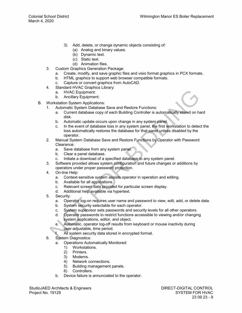
Colonial School District Wilmington Manor ES Boiler ReplacementMarch 4, 2020
StudioJAED Architects & EngineersProject No. 19129
DIRECT-DIGITAL CONTROLSYSTEM FOR HVAC
23 09 23 - 9
3) Add, delete, or change dynamic objects consisting of:(a) Analog and binary values.(b) Dynamic text.(c) Static text.(d) Animation files.
3. Custom Graphics Generation Package:a. Create, modify, and save graphic files and visio format graphics in PCX formats.b. HTML graphics to support web browser compatible formats.c. Capture or convert graphics from AutoCAD.
4. Standard HVAC Graphics Library:a. HVAC Equipment:b. Ancillary Equipment:
B. Workstation System Applications:1. Automatic System Database Save and Restore Functions:
a. Current database copy of each Building Controller is automatically stored on harddisk.
b. Automatic update occurs upon change in any system panel.c. In the event of database loss in any system panel, the first workstation to detect the
loss automatically restores the database for that panel unless disabled by theoperator.
2. Manual System Database Save and Restore Functions by Operator with PasswordClearance:a. Save database from any system panel.b. Clear a panel database.c. Initiate a download of a specified database to any system panel.
3. Software provided allows system configuration and future changes or additions byoperators under proper password protection.
4. On-line Help:a. Context-sensitive system assists operator in operation and editing.b. Available for all applications.c. Relevant screen data provided for particular screen display.d. Additional help available via hypertext.
5. Security:a. Operator log-on requires user name and password to view, edit, add, or delete data.b. System security selectable for each operator.c. System supervisor sets passwords and security levels for all other operators.d. Operator passwords to restrict functions accessible to viewing and/or changing
system applications, editor, and object.e. Automatic, operator log-off results from keyboard or mouse inactivity during
user-adjustable, time period.f. All system security data stored in encrypted format.
6. System Diagnostics:a. Operations Automatically Monitored:
1) Workstations.2) Printers.3) Modems.4) Network connections.5) Building management panels.6) Controllers.
b. Device failure is annunciated to the operator.
NOT FOR B
IDDIN
G

Wilmington Manor ES Boiler Replacement Colonial School DistrictMarch 4, 2020
DIRECT-DIGITAL CONTROL SYSTEM FOR HVAC StudioJAED Architects & Engineers23 09 23 - 10 Project No. 19129
7. Alarm Processing:a. All system objects are configurable to "alarm in" and "alarm out" of normal state.b. Configurable Objects:
1) Alarm limits.2) Alarm limit differentials.3) States.4) Reactions for each object.
8. Alarm Messages:a. Descriptor: English language.b. Recognizable Features:
1) Source.2) Location.3) Nature.
9. Configurable Alarm Reactions by Workstation and Time of Day:a. Logging.b. Printing.c. Starting programs.d. Displaying messages.e. Dialing out to remote locations.f. Paging.g. Providing audible annunciation.h. Displaying specific system graphics.
10. Custom Trend Logs:a. Definable for any data object in the system including interval, start time, and stop
time.b. Trend Data:
1) Sampled and stored on the building controller panel.2) Archivable on hard disk.3) Retrievable for use in reports, spreadsheets and standard database programs.4) Archival on LAN accessible storage media including hard disk, tape, Raid array
drive, and virtual cloud environment.5) Protected and encrypted format to prevent manipulation, or editing of historical
data and event logs.11. Alarm and Event Log:
a. View all system alarms and change of states from any system location.b. Events listed chronologically.c. Operator with proper security acknowledges and clears alarms.d. Alarms not cleared by operator are archived to the workstation hard disk.
12. Object, Property Status and Control:a. Provide a method to view, edit if applicable, the status of any object and property in
the system.b. Status Available by the Following Methods:
1) Menu.2) Graphics.3) Custom Programs.
13. Reports and Logs:a. Reporting Package:
1) Allows operator to select, modify, or create reports.2) Definable as to data content, format, interval, and date.3) Archivable to hard disk.
b. Real-time logs available by type or status such as alarm, lockout, normal, etc.
NOT FOR B
IDDIN
G

Colonial School District Wilmington Manor ES Boiler ReplacementMarch 4, 2020
StudioJAED Architects & EngineersProject No. 19129
DIRECT-DIGITAL CONTROLSYSTEM FOR HVAC
23 09 23 - 11
c. Stored on hard disk and readily accessible by standard software applications,including spreadsheets and word processing.
d. Set to be printed on operator command or specific time(s).14. Reports:
a. Standard:1) Objects with current values.2) Current alarms not locked out.3) Disabled and overridden objects, points and SNVTs.4) Objects in manual or automatic alarm lockout.5) Objects in alarm lockout currently in alarm.6) Logs:
(a) Alarm History.(b) System messages.(c) System events.(d) Trends.
b. Custom:1) Daily.2) Weekly.3) Monthly.4) Annual.5) Time and date stamped.6) Title.7) Facility name.
c. Tenant Override:1) Monthly report showing total, requested, after-hours HVAC and lighting services
on a daily basis for each tenant.2) Annual report showing override usage on a monthly basis.
d. Electrical, Fuel, and Weather:1) Electrical Meter(s):
(a) Monthly showing daily electrical consumption and peak electrical demandwith time and date stamp for each meter.
(b) Annual summary showing monthly electrical consumption and peak demandwith time and date stamp for each meter.
2) Fuel Meter(s):(a) Monthly showing daily natural gas consumption for each meter.(b) Annual summary showing monthly consumption for each meter.
3) Weather:(a) Monthly showing minimum, maximum, average outdoor air temperature and
heating/cooling degree-days for the month.C. Workstation Applications Editors:
1. Provide editing software for all system applications at the PC workstation.2. Downloaded application is executed at controller panel.3. Full screen editor for each application allows operator to view and change:
a. Configuration.b. Name.c. Control parameters.d. Set-points.
4. Scheduling:a. Monthly calendar indicates schedules, holidays, and exceptions.b. Allows several related objects to be scheduled and copied to other objects or dates.
NOT FOR B
IDDIN
G
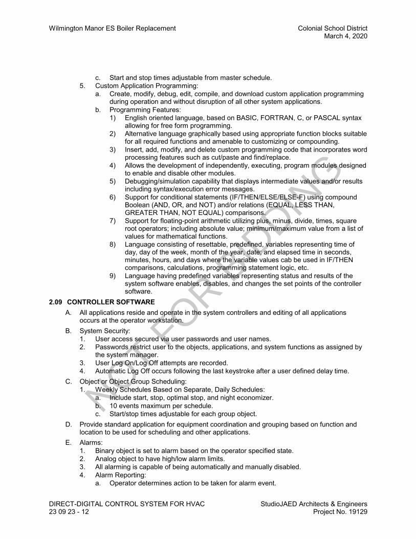
Wilmington Manor ES Boiler Replacement Colonial School DistrictMarch 4, 2020
DIRECT-DIGITAL CONTROL SYSTEM FOR HVAC StudioJAED Architects & Engineers23 09 23 - 12 Project No. 19129
c. Start and stop times adjustable from master schedule.5. Custom Application Programming:
a. Create, modify, debug, edit, compile, and download custom application programmingduring operation and without disruption of all other system applications.
b. Programming Features:1) English oriented language, based on BASIC, FORTRAN, C, or PASCAL syntax
allowing for free form programming.2) Alternative language graphically based using appropriate function blocks suitable
for all required functions and amenable to customizing or compounding.3) Insert, add, modify, and delete custom programming code that incorporates word
processing features such as cut/paste and find/replace.4) Allows the development of independently, executing, program modules designed
to enable and disable other modules.5) Debugging/simulation capability that displays intermediate values and/or results
including syntax/execution error messages.6) Support for conditional statements (IF/THEN/ELSE/ELSE-F) using compound
Boolean (AND, OR, and NOT) and/or relations (EQUAL, LESS THAN,GREATER THAN, NOT EQUAL) comparisons.
7) Support for floating-point arithmetic utilizing plus, minus, divide, times, squareroot operators; including absolute value; minimum/maximum value from a list ofvalues for mathematical functions.
8) Language consisting of resettable, predefined, variables representing time ofday, day of the week, month of the year, date; and elapsed time in seconds,minutes, hours, and days where the variable values cab be used in IF/THENcomparisons, calculations, programming statement logic, etc.
9) Language having predefined variables representing status and results of thesystem software enables, disables, and changes the set points of the controllersoftware.
2.09 CONTROLLER SOFTWAREA. All applications reside and operate in the system controllers and editing of all applications
occurs at the operator workstation.B. System Security:
1. User access secured via user passwords and user names.2. Passwords restrict user to the objects, applications, and system functions as assigned by
the system manager.3. User Log On/Log Off attempts are recorded.4. Automatic Log Off occurs following the last keystroke after a user defined delay time.
C. Object or Object Group Scheduling:1. Weekly Schedules Based on Separate, Daily Schedules:
a. Include start, stop, optimal stop, and night economizer.b. 10 events maximum per schedule.c. Start/stop times adjustable for each group object.
D. Provide standard application for equipment coordination and grouping based on function andlocation to be used for scheduling and other applications.
E. Alarms:1. Binary object is set to alarm based on the operator specified state.2. Analog object to have high/low alarm limits.3. All alarming is capable of being automatically and manually disabled.4. Alarm Reporting:
a. Operator determines action to be taken for alarm event.
NOT FOR B
IDDIN
G

Colonial School District Wilmington Manor ES Boiler ReplacementMarch 4, 2020
StudioJAED Architects & EngineersProject No. 19129
DIRECT-DIGITAL CONTROLSYSTEM FOR HVAC
23 09 23 - 13
b. Alarms to be routed to appropriate workstation.c. Reporting Options:
F. Maintenance Management: System monitors equipment status and generates maintenancemessages based upon user-designated run-time limits.
G. Sequencing: Application software based upon specified sequences of operation in Section 2309 93.
H. PID Control Characteristics:1. Direct or reverse action.2. Anti-windup.3. Calculated, time-varying, analog value, positions an output or stages a series of outputs.4. User selectable controlled variable, set-point, and PED gains.
I. Staggered Start Application:1. Prevents all controlled equipment from simultaneously restarting after power outage.2. Order of equipment startup is user selectable.
J. Energy Calculations:1. Accumulated instantaneous power or flow rates are converted to energy use data.2. Algorithm calculates a rolling average and allows window of time to be user specified in
minute intervals.3. Algorithm calculates a fixed window average with a digital input signal from a utility meter
defining the start of the window period that in turn synchronizes the fixed-window averagewith that used by the power company.
K. Anti-Short Cycling:1. All binary output objects protected from short-cycling.2. Allows minimum on-time and off-time to be selected.
L. On-Off Control with Differential:1. Algorithm allows binary output to be cycled based on a controlled variable and set-point.2. Algorithm to be direct-acting or reverse-acting incorporating an adjustable differential.
M. Run-Time Totalization:1. Totalize run-times for all binary input objects.2. Provides operator with capability to assign high run-time alarm.
2.10 OPERATING SYSTEM SOFTWAREA. Input/Output Capability From Operator Station:
1. Request display of current values or status in tabular or graphic format.2. Command selected equipment to specified state.3. Initiate logs and reports.4. Change analog limits.5. Add, delete, or change points within each control unit or application routine.6. Change point input/output descriptors, status, alarm descriptors, and engineering unit
descriptors.7. Add new control units to system.8. Modify and set up maintenance scheduling parameters.9. Develop, modify, delete or display full range of color graphic displays.10. Automatically archive select data even when running third party software.11. Provide capability to sort and extract data from archived files and to generate custom
reports.12. Support two printer operations.
a. Alarm printer: Print alarms, operator acknowledgements, action messages, systemalarms, operator sign-on and sign-off.
NOT FOR B
IDDIN
G

Wilmington Manor ES Boiler Replacement Colonial School DistrictMarch 4, 2020
DIRECT-DIGITAL CONTROL SYSTEM FOR HVAC StudioJAED Architects & Engineers23 09 23 - 14 Project No. 19129
b. Data printer: Print reports, page prints, and data base prints.13. Select daily, weekly or monthly as scheduled frequency to synchronize time and date in
digital control units. Accommodate daylight savings time adjustments.14. Print selected control unit data base.
B. Operator System Access: Via software password with minimum 30 access levels at workstation and minimum 3 access levels at each control unit.
C. Data Base Creation and Support: Changes shall utilize standard procedures. Control unit shallautomatically check work station data base files upon connection and verify data base match. Minimum capability shall include:1. Add and delete points.2. Modify any point parameter.3. Change, add, or delete English language descriptors.4. Add, modify, or delete alarm limits.5. Add, modify, or delete points in start/stop programs, trend logs, etc.6. Create custom relationship between points.7. Create or modify DDC loops and parameters.8. Create or modify override parameters.9. Add, modify, and delete any applications program.10. Add, delete, develop, or modify dynamic color graphic displays.
D. Dynamic Color Graphic Displays:1. Utilizes custom symbols or system supported library of symbols.2. Sixteen (16) colors.3. Sixty (60) outputs of real time, live dynamic data per graphic.4. Dynamic graphic data.5. 1,000 separate graphic pages.6. Modify graphic screen refresh rate between 1 and 60 seconds.
E. Operator Station:1. Accept data from LAN as needed without scanning entire network for updated point data.2. Interrogate LAN for updated point data when requested.3. Allow operator command of devices.4. Allow operator to place specific control units in or out of service.5. Allow parameter editing of control units.6. Store duplicate data base for every control unit and allow down loading while system is on
line.7. Control or modify specific programs.8. Develop, store and modify dynamic color graphics.9. Provide data archiving of assigned points and support overlay graphing of this data utilizing
up to four (4) variables.F. Alarm Processing:
1. Off normal condition: Cause alarm and appropriate message, including time, system,point descriptor, and alarm condition. Select alarm state/value and which alarms shallcause automatic dial-out.
2. Critical alarm or change-of-state: Display message, stored on disk for review and sort, orprint.
3. Print on line changeable message, up to 100 characters in length, for each alarm pointspecified.
4. Display alarm reports on video. Display multiple alarms in order of occurrence.5. Define time delay for equipment start-up or shutdown.6. Allow unique routing of specific alarms.7. Operator specifies if alarm requires acknowledgement.
NOT FOR B
IDDIN
G

Colonial School District Wilmington Manor ES Boiler ReplacementMarch 4, 2020
StudioJAED Architects & EngineersProject No. 19129
DIRECT-DIGITAL CONTROLSYSTEM FOR HVAC
23 09 23 - 15
8. Continue to indicate unacknowledged alarms after return to normal.9. Alarm notification:
a. Automatic print.b. Display indicating alarm condition.c. Selectable audible alarm indication.
G. Event Processing: Automatically initiate commands, user defined messages, take specificcontrol actions or change control strategy and application programs resulting from eventcondition. Event condition may be value crossing operator defined limit, change-of-state,specified state, or alarm occurrence or return to normal.
H. Automatic Restart: Automatically restart field equipment on restoration of power. Provide timedelay between individual equipment restart and time of day start/stop.
I. Messages:1. Automatically display or print user-defined message subsequent to occurrence of selected
events.2. Compose, change, or delete any message.3. Display or log any message at any time.4. Assign any message to any event.
J. Reports:1. Manually requested with time and date.2. Long term data archiving to hard disk.3. Automatic directives to download to transportable media such as floppy diskettes for
storage.4. Data selection methods to include data base search and manipulation.5. Data extraction with mathematical manipulation.6. Data reports shall allow development of XY curve plotting, tabular reports (both statistical
and summary), and multi-point timed based plots with not less than four (4) variablesdisplayed.
7. Generating reports either normally at operator direction, or automatically under workstation direction.
8. Reports may either manually displayed or printed, or may be printed automatically on daily,weekly, monthly, yearly or scheduled basis.
9. Include capability for statistical data manipulation and extraction.10. Provide capability to generate four types of reports: Statistical detail reports, summary
reports, trend graphic plots, x-y graphic plots.K. Parameter Save/Restore: Store most current operating system, parameter changes, and
modifications on disk or diskette.L. Data Collection:
1. Automatically collect and store in disk files.2. Daily electrical energy consumption, peak demand, and time of peak demand for up to
electrical meters over 2 year period.3. Daily consumption for up to 30 meters over a 2 year period.4. Daily billable electrical energy consumption and time for up to 1024 zones over a 10 year
period.5. Provide archiving of stored data for use with system supplied custom reports.
M. Graphic Display: Support graphic development on work station with software features:1. Page linking.2. Generate, store, and retrieve library symbols.3. Single or double height characters.4. Sixty (60) dynamic points of data per graphic page.
NOT FOR B
IDDIN
G
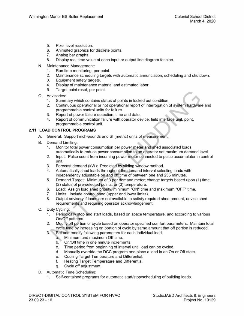
Wilmington Manor ES Boiler Replacement Colonial School DistrictMarch 4, 2020
DIRECT-DIGITAL CONTROL SYSTEM FOR HVAC StudioJAED Architects & Engineers23 09 23 - 16 Project No. 19129
5. Pixel level resolution.6. Animated graphics for discrete points.7. Analog bar graphs.8. Display real time value of each input or output line diagram fashion.
N. Maintenance Management:1. Run time monitoring, per point.2. Maintenance scheduling targets with automatic annunciation, scheduling and shutdown.3. Equipment safety targets.4. Display of maintenance material and estimated labor.5. Target point reset, per point.
O. Advisories:1. Summary which contains status of points in locked out condition.2. Continuous operational or not operational report of interrogation of system hardware and
programmable control units for failure.3. Report of power failure detection, time and date.4. Report of communication failure with operator device, field interface unit, point,
programmable control unit.2.11 LOAD CONTROL PROGRAMS
A. General: Support inch-pounds and SI (metric) units of measurement.B. Demand Limiting:
1. Monitor total power consumption per power meter and shed associated loadsautomatically to reduce power consumption to an operator set maximum demand level.
2. Input: Pulse count from incoming power meter connected to pulse accumulator in controlunit.
3. Forecast demand (kW): Predicted by sliding window method.4. Automatically shed loads throughout the demand interval selecting loads with
independently adjustable on and off time of between one and 255 minutes.5. Demand Target: Minimum of 3 per demand meter; change targets based upon (1) time,
(2) status of pre-selected points, or (3) temperature.6. Load: Assign load shed priority, minimum "ON" time and maximum "OFF" time.7. Limits: Include control band (upper and lower limits).8. Output advisory if loads are not available to satisfy required shed amount, advise shed
requirements and requiring operator acknowledgement.C. Duty Cycling:
1. Periodically stop and start loads, based on space temperature, and according to variousOn/Off patterns.
2. Modify off portion of cycle based on operator specified comfort parameters. Maintain totalcycle time by increasing on portion of cycle by same amount that off portion is reduced.
3. Set and modify following parameters for each individual load.a. Minimum and maximum Off time.b. On/Off time in one minute increments.c. Time period from beginning of interval until load can be cycled.d. Manually override the DCC program and place a load in an On or Off state.e. Cooling Target Temperature and Differential.f. Heating Target Temperature and Differential.g. Cycle off adjustment.
D. Automatic Time Scheduling:1. Self-contained programs for automatic start/stop/scheduling of building loads.
NOT FOR B
IDDIN
G

Colonial School District Wilmington Manor ES Boiler ReplacementMarch 4, 2020
StudioJAED Architects & EngineersProject No. 19129
DIRECT-DIGITAL CONTROLSYSTEM FOR HVAC
23 09 23 - 17
2. Support up to seven (7) normal day schedules, seven (7) "special day" schedules and two(2) temporary day schedules.
3. Special days schedule shall support up to 30 unique date/duration combinations.4. Any number of loads assigned to any time program; each load can have individual time
program.5. Each load assigned at least 16 control actions per day with 1 minute resolution.6. Time schedule operations may be:
a. Start.b. Optimized Start.c. Stop.d. Optimized Stop.e. Cycle.f. Optimized Cycle.
7. Minimum of 30 holiday periods up to 100 days in length may be specified for the year.8. Create temporary schedules.9. Broadcast temporary "special day" date and duration.
E. Start/Stop Time Optimization:1. Perform optimized start/stop as function of outside conditions, inside conditions, or both.2. Adaptive and self-tuning, adjusting to changing conditions unattended.3. For each point under control, establish and modify:
a. Occupancy period.b. Desired temperature at beginning of occupancy period.c. Desired temperature at end of occupancy period.
F. Night Setback/Setup Program: Reduce heating space temperature setpoint or raise coolingspace temperature setpoint during unoccupied hours; in conjunction with scheduled start/stopand optimum start/stop programs.
G. Calculated Points: Define calculations and totalization computed from monitored points(analog/digital points), constants, or other calculated points.1. Employ arithmetic, algebraic, Boolean, and special function operations.2. Treat calculated values like any other analog value, use for any function that a "hard wired
point" might be used.H. Event Initiated Programming: Event may be initiated by any data point, causing series of
controls in a sequence.1. Define time interval between each control action between 0 to 3600 seconds.2. Output may be analog value.3. Provide for "skip" logic.4. Verify completion of one action before proceeding to next. If not verified, program shall be
able to skip to next action.I. Direct Digital Control: Each control unit shall provide Direct Digital Control software so that the
operator may customize control strategies and sequences of operation by defining theappropriate control loop algorithms and choosing the optimum loop parameters.1. Control loops: Defined using "modules" that are analogous to standard control devices.2. Output: Paired or individual digital outputs for pulse-width modulation, and analog outputs,
as required.3. Firmware:
a. PID with analog or pulse-width modulation output.b. Floating control with pulse-width modulated outputs.c. Two-position control.d. Primary and secondary reset schedule selector.
NOT FOR B
IDDIN
G
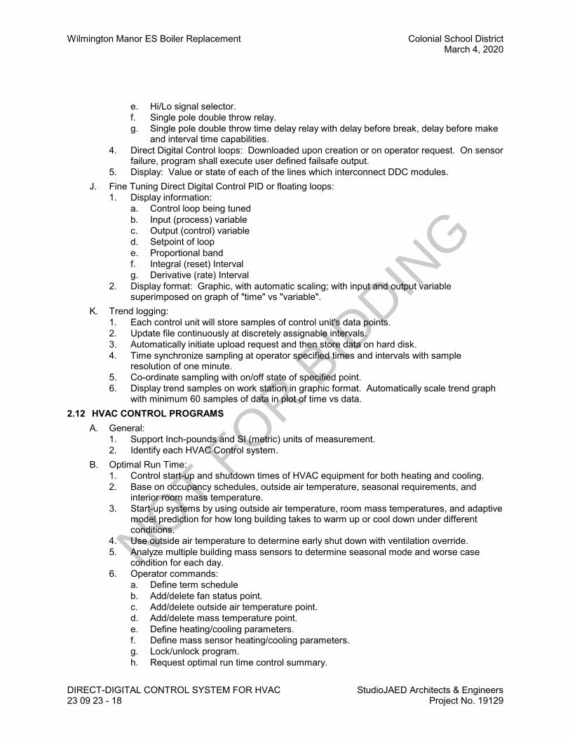
Wilmington Manor ES Boiler Replacement Colonial School DistrictMarch 4, 2020
DIRECT-DIGITAL CONTROL SYSTEM FOR HVAC StudioJAED Architects & Engineers23 09 23 - 18 Project No. 19129
e. Hi/Lo signal selector.f. Single pole double throw relay.g. Single pole double throw time delay relay with delay before break, delay before make
and interval time capabilities.4. Direct Digital Control loops: Downloaded upon creation or on operator request. On sensor
failure, program shall execute user defined failsafe output.5. Display: Value or state of each of the lines which interconnect DDC modules.
J. Fine Tuning Direct Digital Control PID or floating loops:1. Display information:
a. Control loop being tunedb. Input (process) variablec. Output (control) variabled. Setpoint of loope. Proportional bandf. Integral (reset) Intervalg. Derivative (rate) Interval
2. Display format: Graphic, with automatic scaling; with input and output variablesuperimposed on graph of "time" vs "variable".
K. Trend logging:1. Each control unit will store samples of control unit's data points.2. Update file continuously at discretely assignable intervals.3. Automatically initiate upload request and then store data on hard disk.4. Time synchronize sampling at operator specified times and intervals with sample
resolution of one minute.5. Co-ordinate sampling with on/off state of specified point.6. Display trend samples on work station in graphic format. Automatically scale trend graph
with minimum 60 samples of data in plot of time vs data.2.12 HVAC CONTROL PROGRAMS
A. General:1. Support Inch-pounds and SI (metric) units of measurement.2. Identify each HVAC Control system.
B. Optimal Run Time:1. Control start-up and shutdown times of HVAC equipment for both heating and cooling.2. Base on occupancy schedules, outside air temperature, seasonal requirements, and
interior room mass temperature.3. Start-up systems by using outside air temperature, room mass temperatures, and adaptive
model prediction for how long building takes to warm up or cool down under differentconditions.
4. Use outside air temperature to determine early shut down with ventilation override.5. Analyze multiple building mass sensors to determine seasonal mode and worse case
condition for each day.6. Operator commands:
a. Define term scheduleb. Add/delete fan status point.c. Add/delete outside air temperature point.d. Add/delete mass temperature point.e. Define heating/cooling parameters.f. Define mass sensor heating/cooling parameters.g. Lock/unlock program.h. Request optimal run time control summary.
NOT FOR B
IDDIN
G

Colonial School District Wilmington Manor ES Boiler ReplacementMarch 4, 2020
StudioJAED Architects & EngineersProject No. 19129
DIRECT-DIGITAL CONTROLSYSTEM FOR HVAC
23 09 23 - 19
i. Request optimal run time mass temperature summary.j. Request HVAC point summary.k. Request HVAC saving profile summary.
7. Control Summary:a. HVAC Control system begin/end status.b. Optimal run time lock/unlock control status.c. Heating/cooling mode status.d. Optimal run time schedule.e. Start/Stop times.f. Selected mass temperature point ID.g. Optimal run time system normal start times.h. Occupancy and vacancy times.i. Optimal run time system heating/cooling mode parameters.
8. Mass temperature summary:a. Mass temperature point type and ID.b. Desired and current mass temperature values.c. Calculated warm-up/cool-down time for each mass temperature.d. Heating/cooling season limits.e. Break point temperature for cooling mode analysis.
9. HVAC point summary:a. Control system identifier and status.b. Point ID and status.c. Outside air temperature point ID and status.d. Mass temperature point ID and point.e. Calculated optimal start and stop times.f. Period start.
C. Supply Air Reset:1. Monitor heating and cooling loads in building spaces, terminal reheat systems, both hot
deck and cold deck temperatures on dual duct and multizone systems, single zone unitdischarge temperatures.
2. Adjust discharge temperatures to most energy efficient levels satisfying measured load by:a. Raising cooling temperatures to highest possible value.b. Reducing heating temperatures to lowest possible level.
3. Operator commands:a. Add/delete fan status point.b. Lock/unlock program.c. Request HVAC point summary.d. Add/Delete discharge controller point.e. Define discharge controller parameters.f. Add/delete air flow rate.g. Define space load and load parameters.h. Request space load summary.
4. Control summary:a. HVAC control system status (begin/end).b. Supply air reset system status.c. Optimal run time system status.d. Heating and cooling loop.e. High/low limits.f. Deadband.g. Response timer.
NOT FOR B
IDDIN
G
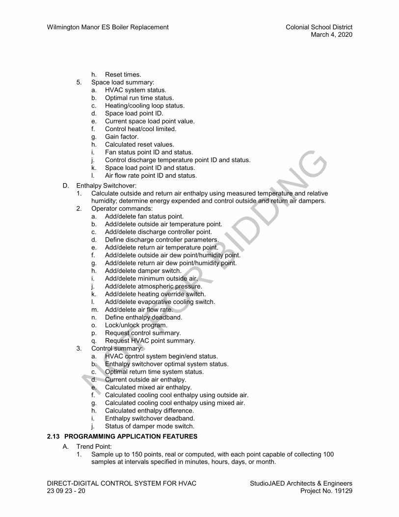
Wilmington Manor ES Boiler Replacement Colonial School DistrictMarch 4, 2020
DIRECT-DIGITAL CONTROL SYSTEM FOR HVAC StudioJAED Architects & Engineers23 09 23 - 20 Project No. 19129
h. Reset times.5. Space load summary:
a. HVAC system status.b. Optimal run time status.c. Heating/cooling loop status.d. Space load point ID.e. Current space load point value.f. Control heat/cool limited.g. Gain factor.h. Calculated reset values.i. Fan status point ID and status.j. Control discharge temperature point ID and status.k. Space load point ID and status.l. Air flow rate point ID and status.
D. Enthalpy Switchover:1. Calculate outside and return air enthalpy using measured temperature and relative
humidity; determine energy expended and control outside and return air dampers.2. Operator commands:
a. Add/delete fan status point.b. Add/delete outside air temperature point.c. Add/delete discharge controller point.d. Define discharge controller parameters.e. Add/delete return air temperature point.f. Add/delete outside air dew point/humidity point.g. Add/delete return air dew point/humidity point.h. Add/delete damper switch.i. Add/delete minimum outside air.j. Add/delete atmospheric pressure.k. Add/delete heating override switch.l. Add/delete evaporative cooling switch.m. Add/delete air flow rate.n. Define enthalpy deadband.o. Lock/unlock program.p. Request control summary.q. Request HVAC point summary.
3. Control summary:a. HVAC control system begin/end status.b. Enthalpy switchover optimal system status.c. Optimal return time system status.d. Current outside air enthalpy.e. Calculated mixed air enthalpy.f. Calculated cooling cool enthalpy using outside air.g. Calculated cooling cool enthalpy using mixed air.h. Calculated enthalpy difference.i. Enthalpy switchover deadband.j. Status of damper mode switch.
2.13 PROGRAMMING APPLICATION FEATURESA. Trend Point:
1. Sample up to 150 points, real or computed, with each point capable of collecting 100samples at intervals specified in minutes, hours, days, or month.
NOT FOR B
IDDIN
G
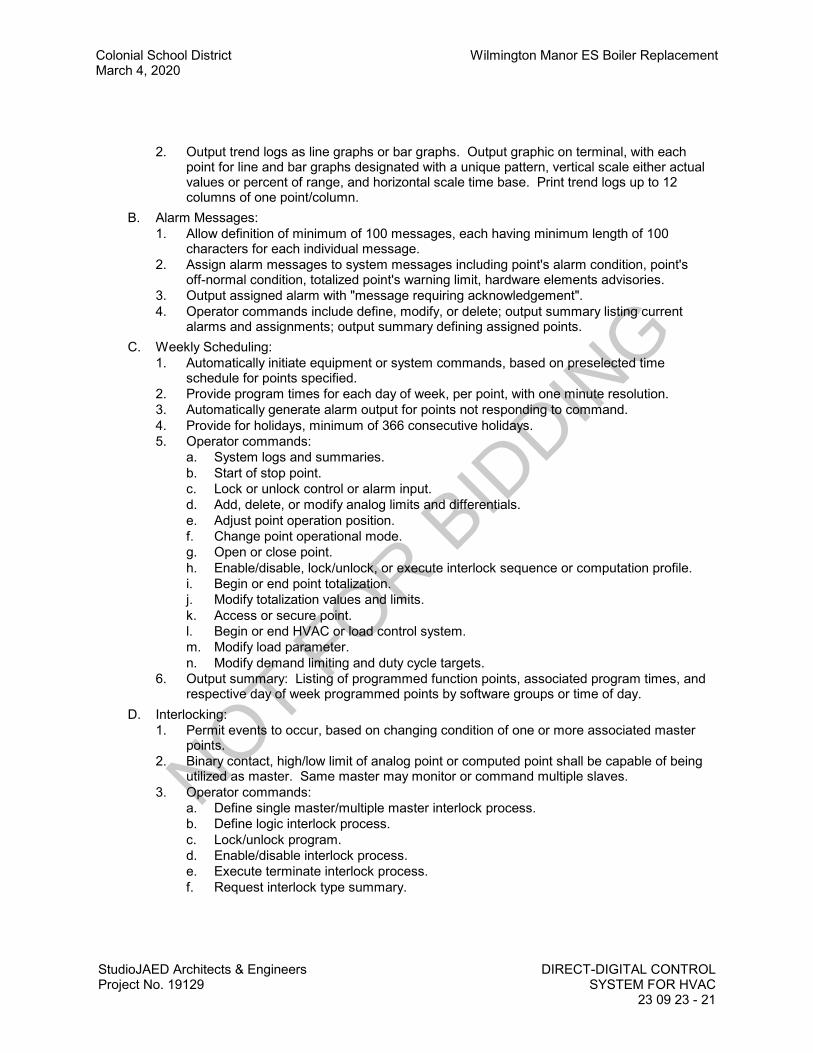
Colonial School District Wilmington Manor ES Boiler ReplacementMarch 4, 2020
StudioJAED Architects & EngineersProject No. 19129
DIRECT-DIGITAL CONTROLSYSTEM FOR HVAC
23 09 23 - 21
2. Output trend logs as line graphs or bar graphs. Output graphic on terminal, with eachpoint for line and bar graphs designated with a unique pattern, vertical scale either actualvalues or percent of range, and horizontal scale time base. Print trend logs up to 12columns of one point/column.
B. Alarm Messages:1. Allow definition of minimum of 100 messages, each having minimum length of 100
characters for each individual message.2. Assign alarm messages to system messages including point's alarm condition, point's
off-normal condition, totalized point's warning limit, hardware elements advisories.3. Output assigned alarm with "message requiring acknowledgement".4. Operator commands include define, modify, or delete; output summary listing current
alarms and assignments; output summary defining assigned points.C. Weekly Scheduling:
1. Automatically initiate equipment or system commands, based on preselected timeschedule for points specified.
2. Provide program times for each day of week, per point, with one minute resolution.3. Automatically generate alarm output for points not responding to command.4. Provide for holidays, minimum of 366 consecutive holidays.5. Operator commands:
a. System logs and summaries.b. Start of stop point.c. Lock or unlock control or alarm input.d. Add, delete, or modify analog limits and differentials.e. Adjust point operation position.f. Change point operational mode.g. Open or close point.h. Enable/disable, lock/unlock, or execute interlock sequence or computation profile.i. Begin or end point totalization.j. Modify totalization values and limits.k. Access or secure point.l. Begin or end HVAC or load control system.m. Modify load parameter.n. Modify demand limiting and duty cycle targets.
6. Output summary: Listing of programmed function points, associated program times, andrespective day of week programmed points by software groups or time of day.
D. Interlocking:1. Permit events to occur, based on changing condition of one or more associated master
points.2. Binary contact, high/low limit of analog point or computed point shall be capable of being
utilized as master. Same master may monitor or command multiple slaves.3. Operator commands:
a. Define single master/multiple master interlock process.b. Define logic interlock process.c. Lock/unlock program.d. Enable/disable interlock process.e. Execute terminate interlock process.f. Request interlock type summary.
NOT FOR B
IDDIN
G

Wilmington Manor ES Boiler Replacement Colonial School DistrictMarch 4, 2020
DIRECT-DIGITAL CONTROL SYSTEM FOR HVAC StudioJAED Architects & Engineers23 09 23 - 22 Project No. 19129
PART 3 EXECUTION3.01 EXAMINATION
A. Verify existing conditions before starting work.B. Verify that conditioned power supply is available to the control units and to the operator work
station. Verify that field end devices, wiring, and pneumatic tubing is installed prior toinstallation proceeding.
3.02 INSTALLATIONA. Install all Owner-provided equipment along with all contractor-provided equipment as required to
provide a complete, fully functional building automation system.B. Install control units and other hardware in position on permanent walls where not subject to
excessive vibration.C. Install software in control units and in operator work station. Implement all features of programs
to specified requirements and appropriate to sequence of operation. Refer to Section 23 09 93.D. Provide with 120v AC, 15 amp dedicated emergency power circuit to each programmable
control unit.E. Provide conduit and electrical wiring in accordance with Section 26 27 17. Electrical material
and installation shall be in accordance with appropriate requirements of .F. Ensure that all components necessary to execute the sequences of operation are coordinated
and installed by all contractors.3.03 MANUFACTURER'S FIELD SERVICES
A. Start and commission systems. Allow sufficient time for start-up and commissioning prior toplacing control systems in permanent operation.
B. Provide service engineer to instruct Owner's representative in operation of systems plant andequipment for 2 day period.
C. Provide basic operator training for 4 persons on data display, alarm and status descriptors,requesting data, execution of commands and request of logs. Include a minimum of 8 hoursdedicated instructor time. Provide training on site.
3.04 DEMONSTRATION AND INSTRUCTIONSA. Demonstrate complete and operating system to Owner.
3.05 SCHEDULESA. Input/Output Schedule:
1. Point Description:2. Digital Input:
a. Demand Meter (kW):b. Auxiliary Contact:c. Switches:
1) Switch Closing:2) Flow Switch:3) Optical:
d. Current:e. Pressure:
3. Digital Output:a. Control Relay:b. Solenoid:c. Contactor:
4. Analog Input:
NOT FOR B
IDDIN
G

Colonial School District Wilmington Manor ES Boiler ReplacementMarch 4, 2020
StudioJAED Architects & EngineersProject No. 19129
DIRECT-DIGITAL CONTROLSYSTEM FOR HVAC
23 09 23 - 23
a. Temperature:b. Relative Humidity:c. Pressure/Vacuum:d. Filter:e. Flow:f. Current:g. Liquid Level:h. Photocell:
5. Analog Output:a. Pneumatic Transducer:b. 4-20 ma Module:c. 0-16 v DC:
6. Alarm:B. Input/Output Schedule:
1. Point Description:2. Inputs:
a. Temperature:b. Relative Humidity:c. Pressure:d. Flow:e. Level:f. Position:g. Energy:h. Power:
3. Outputs:a. Status:b. Alarm:c. Pneumatic Position:d. Electronic Position:e. Set Point Adjust:f. Start/Stop:g. Off/Low/High:
4. Software Features:a. PID Control (DDC):b. High Limit:c. Low Limit:d. Run Time Totalization:e. Consumption Totalization:f. Program Start/Stop:g. Load Shed:h. Duty Cycle:i. Enthalpy Switchover:j. Optimal Run Time:k. Supply Air Reset:l. O.A. Interlock:m. O.A. Temperature Reset:n. Free Cooling Mode:o. Warm-up Mode:p. Boiler Interlock:q. Chiller Sequencing:
NOT FOR B
IDDIN
G

Wilmington Manor ES Boiler Replacement Colonial School DistrictMarch 4, 2020
DIRECT-DIGITAL CONTROL SYSTEM FOR HVAC StudioJAED Architects & Engineers23 09 23 - 24 Project No. 19129
r. Energy Calculation:C. Alarm Schedule:
1. High Limit: A1.2. Low Limit: A2.3. Run Time: A3.4. Maintenance: A4.5. Status: A5.6. Override: A6.7. Freeze: A7.8. Low Pressure: A8.
END OF SECTION
NOT FOR B
IDDIN
G
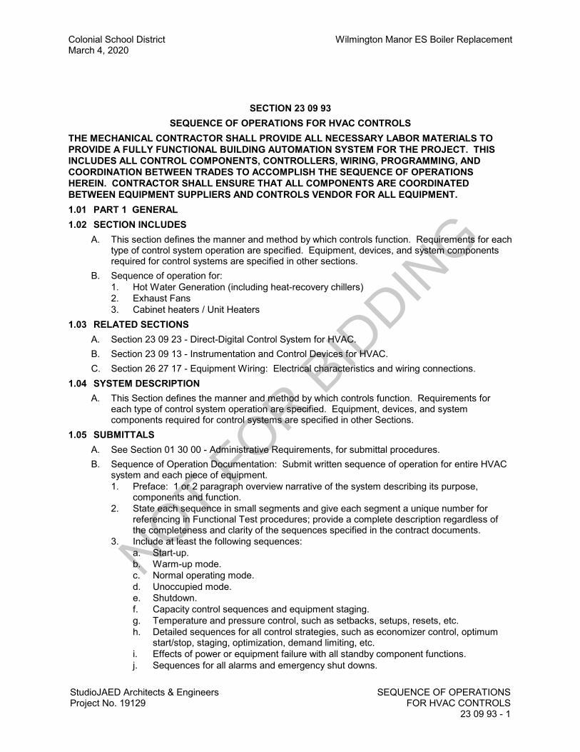
Colonial School District Wilmington Manor ES Boiler ReplacementMarch 4, 2020
StudioJAED Architects & EngineersProject No. 19129
SEQUENCE OF OPERATIONSFOR HVAC CONTROLS
23 09 93 - 1
SECTION 23 09 93SEQUENCE OF OPERATIONS FOR HVAC CONTROLS
THE MECHANICAL CONTRACTOR SHALL PROVIDE ALL NECESSARY LABOR MATERIALS TOPROVIDE A FULLY FUNCTIONAL BUILDING AUTOMATION SYSTEM FOR THE PROJECT. THISINCLUDES ALL CONTROL COMPONENTS, CONTROLLERS, WIRING, PROGRAMMING, ANDCOORDINATION BETWEEN TRADES TO ACCOMPLISH THE SEQUENCE OF OPERATIONSHEREIN. CONTRACTOR SHALL ENSURE THAT ALL COMPONENTS ARE COORDINATEDBETWEEN EQUIPMENT SUPPLIERS AND CONTROLS VENDOR FOR ALL EQUIPMENT.1.01 PART 1 GENERAL1.02 SECTION INCLUDES
A. This section defines the manner and method by which controls function. Requirements for eachtype of control system operation are specified. Equipment, devices, and system componentsrequired for control systems are specified in other sections.
B. Sequence of operation for:1. Hot Water Generation (including heat-recovery chillers)2. Exhaust Fans3. Cabinet heaters / Unit Heaters
1.03 RELATED SECTIONSA. Section 23 09 23 - Direct-Digital Control System for HVAC.B. Section 23 09 13 - Instrumentation and Control Devices for HVAC.C. Section 26 27 17 - Equipment Wiring: Electrical characteristics and wiring connections.
1.04 SYSTEM DESCRIPTIONA. This Section defines the manner and method by which controls function. Requirements for
each type of control system operation are specified. Equipment, devices, and systemcomponents required for control systems are specified in other Sections.
1.05 SUBMITTALSA. See Section 01 30 00 - Administrative Requirements, for submittal procedures.B. Sequence of Operation Documentation: Submit written sequence of operation for entire HVAC
system and each piece of equipment.1. Preface: 1 or 2 paragraph overview narrative of the system describing its purpose,
components and function.2. State each sequence in small segments and give each segment a unique number for
referencing in Functional Test procedures; provide a complete description regardless ofthe completeness and clarity of the sequences specified in the contract documents.
3. Include at least the following sequences:a. Start-up.b. Warm-up mode.c. Normal operating mode.d. Unoccupied mode.e. Shutdown.f. Capacity control sequences and equipment staging.g. Temperature and pressure control, such as setbacks, setups, resets, etc.h. Detailed sequences for all control strategies, such as economizer control, optimum
start/stop, staging, optimization, demand limiting, etc.i. Effects of power or equipment failure with all standby component functions.j. Sequences for all alarms and emergency shut downs.
NOT FOR B
IDDIN
G

Wilmington Manor ES Boiler Replacement Colonial School DistrictMarch 4, 2020
SEQUENCE OF OPERATIONS FOR HVAC CONTROLSStudioJAED Architects & Engineers23 09 93 - 2 Project No. 19129
k. Seasonal operational differences and recommendations.l. Interactions and interlocks with other systems.
4. Include initial and recommended values for all adjustable settings, setpoints andparameters that are typically set or adjusted by operating staff; and any other controlsettings or fixed values, delays, etc. that will be useful during testing and operating theequipment.
5. For packaged controlled equipment, include manufacturer's furnished sequence ofoperation amplified as required to describe the relationship between the packaged controlsand the control system, indicating which points are adjustable control points and whichpoints are only monitored.
6. Include schedules, if known.C. Control System Diagrams: Submit graphic schematic of the control system showing each
control component and each component controlled, monitored, or enabled.1. Label with settings, adjustable range of control and limits.2. Include flow diagrams for each control system, graphically depicting control logic.3. Include the system and component layout of all equipment that the control system
monitors, enables or controls, even if the equipment is primarily controlled by packaged orintegral controls.
4. Include draft copies of graphic displays indicating mechanical system components, controlsystem components, and controlled function status and value.
5. Include all monitoring, control and virtual points specified in elsewhere.6. Include a key to all abbreviations.
D. Points List: Submit list of all control points indicating at least the following for each point.1. Name of controlled system.2. Point abbreviation.3. Point description; such as dry bulb temperature, airflow, etc.4. Display unit.5. Control point or setpoint (Yes / No); i.e. a point that controls equipment and can have its
setpoint changed.6. Monitoring point (Yes / No); i.e. a point that does not control or contribute to the control of
equipment but is used for operation, maintenance, or performance verification.7. Intermediate point (Yes / No); i.e. a point whose value is used to make a calculation which
then controls equipment, such as space temperatures that are averaged to a virtual pointto control reset.
8. Calculated point (Yes / No); i.e. a “virtual” point generated from calculations of other pointvalues.
E. Project Record Documents: Record actual locations of components and setpoints of controls,including changes to sequences made after submission of shop drawings.
1.06 QUALITY ASSURANCEA. Design system under direct supervision of a Professional Engineer experienced in design of this
Work and licensed in the State in which the Project is located.PART 2 PRODUCTS - NOT USEDPART 3 EXECUTION3.01 GENERAL SYSTEM DESIGN AND OPERATION STANDARDS
A. The BAS shall control the mechanical systems within the site based upon the following designparameters:1. Central heating plant consisting of two condensing boilers with individual constant-volume
primary circulators feeding a constant flow secondary loop.
NOT FOR B
IDDIN
G

Colonial School District Wilmington Manor ES Boiler ReplacementMarch 4, 2020
StudioJAED Architects & EngineersProject No. 19129
SEQUENCE OF OPERATIONSFOR HVAC CONTROLS
23 09 93 - 3
B. Each unit shall be controlled by an individual DDC Controller and all required sensors, controlvalves, and appurtenances required to complete the sequence of operation. Units shall includeoccupied/unoccupied control, night-setback, morning warm-up/cool-down, and enthalpy-basedeconomizer functions.
3.02 HEATING WATER SYSTEMA. General
1. The heating water system shall be manually enabled and disabled from the operatorworkstation.
2. Heating lockout shall prevent heating water system from operating if outdoor airtemperature rises above 60 F (adj.).a. NOTE: On a loss of input signal from the global BAS tmeperature and enthalpy
sensor the boilers shall default to operational mode.B. Condensing Boilers
1. The boilers shall be enabled / disabled by the BAS based on manual operator command. Once enabled, the boiler's integrated combustion controls and integral thermostat shallcycle the boiler and adjust firing rates to maintain the designated loop temperature per thereset schedule.
2. When the designated lead boiler is enabled, its associated circulator pump shall runcontinuously. Operation of the circulator pump must be proven via a flow switch beforethe boiler is allowed to fire. An alarm shall be activated at the Operator's Terminal if pumpoperation is not detected when pump is commanded to operate.
3. The BAS shall monitor a general failure alarm and a low water cut off alarm from eachboiler.
4. When an alarm is detected at the designated lead boiler, it shall be disabled by the BASand the designated lag boiler shall be enabled while an alarm is generated at theOperator's Terminal.
5. If the lead boiler is unable to maintain the heating load as detected by the hot water loopreturn temperature sensor, the designated lag pump and boiler shall be activated.
C. Building Water Loop1. When the heating system is enabled via manual operator command, the designated lead
pump shall run continuously.2. On a loss of flow, as indicated by a differential pressure switch, a “heating water loop
failure” shall be indicated at the operator's terminal.3. Pumps shall automatically alternate lead status weekly via the BAS.4. The building system loop temperature sensor shall control the boilers via the temperature
cut-offs to provide building loop heating water reset based on outdoor temperature.a. Reset Schedule:b. Outdoor TemperatureBuilding Loop Temperature (all temperatures user adjustable)
1) <30 ºF = 180 ºF2) <35 ºF = 170 ºF3) <45 ºF = 160 ºF4) <50 ºF = 140 ºF
D. Heating Water System Monitoring - The following points shall be monitored:1. Building Loop Supply Temperature (Each Sub Loop)2. Building Loop Return Temperature (Each Sub Loop)3. Boiler Loop Supply Temperature4. Boiler Loop Return Temperature5. Boiler temperature setpoint6. Boiler Status Contacts
NOT FOR B
IDDIN
G

Wilmington Manor ES Boiler Replacement Colonial School DistrictMarch 4, 2020
SEQUENCE OF OPERATIONS FOR HVAC CONTROLSStudioJAED Architects & Engineers23 09 93 - 4 Project No. 19129
a. Boiler Alarm Contacts7. Boiler low water cut off8. Building Loop Circulator and recirculator pump(s) status via current switch9. Building Loop pump flow status via differential pressure switch10. Diagram showing the layout of the boiler room, boiler loop, chiller heat recovery loops, and
building loop with major components and dynamic temperatures shown where temperaturesensors exist in the system
3.03 EXHAUST FANSA. Exhaust Fans Serving Mechanical And Electrical Rooms
1. Unless otherwise noted, exhaust fans serving mechanical rooms / spaces shall becontrolled by thermostat to maintain a target temperature (80 degrees F, user adjustable).
2. If the the exhaust fan is linked to an associated louver and MOD, the damper shall openon a call for the exhaust fan to energize. Provide end-switch for damper status.
3. Once the temperature has been met, the exhaust fan shall be de-energized and the MODshall close
3.04 HYDRONIC HEATERS / UNIT HEATERSA. User-adjustable temperature maintained by DDC controller and locat thermostat set at 68
degrees F (adjustable) maintains constant space temperature by cycling unit fan motor andassocated control valve.
B. In cooling mode, the unit is de-energized and the control valve remains closed.C. The following items shall be displayed at the Operator's Terminal:
1. Temperature Setpoint.2. Actual space temperature.3. Commanded position of control valve.4. Commanded status of fan motor.
3.05 EXHAUST FANS FOR ELECTRICAL ROOMS AND MECHANICAL ROOMSA. ELECTRICAL ROOMS: On room temperatures above 95 degrees F open intake damper and
start exhaust fan.B. MECHANICAL ROOMS: Fan shall run continously and be monintored by the BAS via CT
sensor.END OF SECTION
NOT FOR B
IDDIN
G
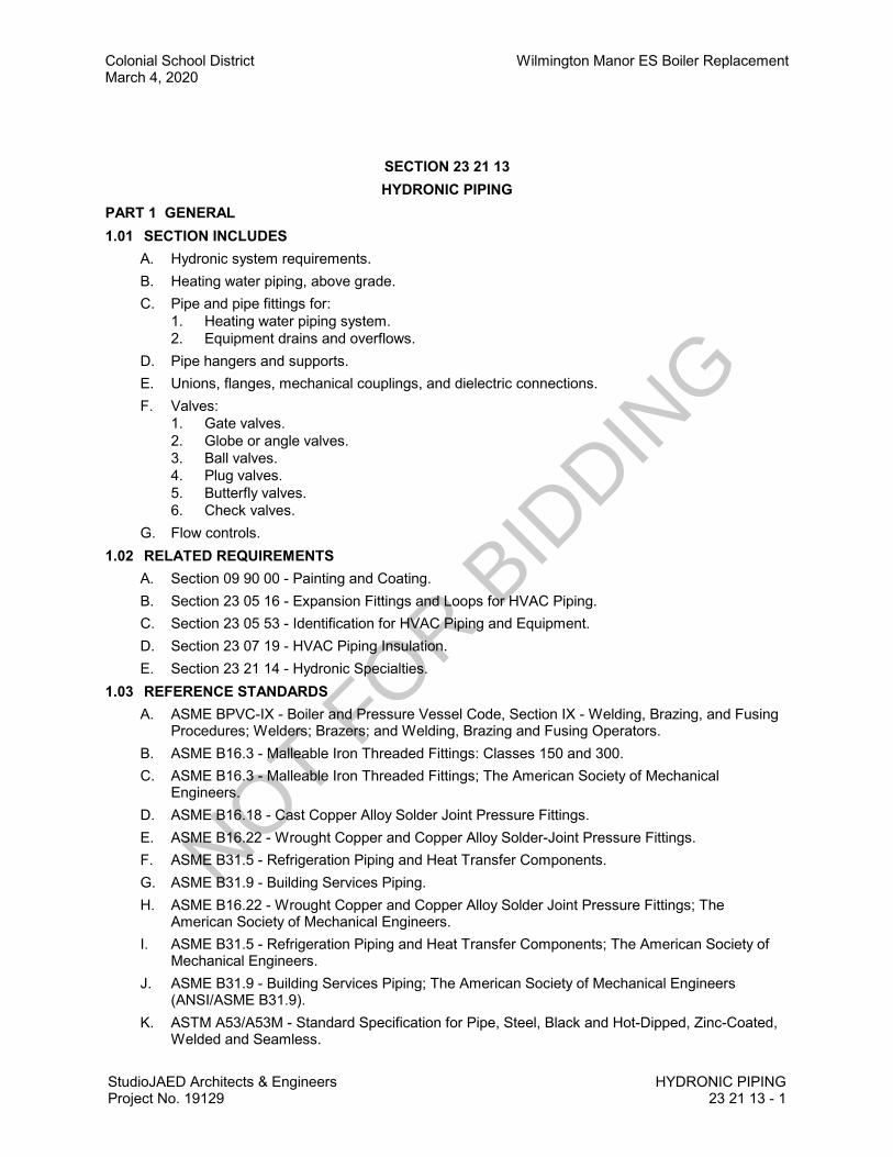
Colonial School District Wilmington Manor ES Boiler ReplacementMarch 4, 2020
StudioJAED Architects & EngineersProject No. 19129
HYDRONIC PIPING23 21 13 - 1
SECTION 23 21 13HYDRONIC PIPING
PART 1 GENERAL1.01 SECTION INCLUDES
A. Hydronic system requirements.B. Heating water piping, above grade.C. Pipe and pipe fittings for:
1. Heating water piping system.2. Equipment drains and overflows.
D. Pipe hangers and supports.E. Unions, flanges, mechanical couplings, and dielectric connections.F. Valves:
1. Gate valves.2. Globe or angle valves.3. Ball valves.4. Plug valves.5. Butterfly valves.6. Check valves.
G. Flow controls.1.02 RELATED REQUIREMENTS
A. Section 09 90 00 - Painting and Coating.B. Section 23 05 16 - Expansion Fittings and Loops for HVAC Piping.C. Section 23 05 53 - Identification for HVAC Piping and Equipment.D. Section 23 07 19 - HVAC Piping Insulation.E. Section 23 21 14 - Hydronic Specialties.
1.03 REFERENCE STANDARDSA. ASME BPVC-IX - Boiler and Pressure Vessel Code, Section IX - Welding, Brazing, and Fusing
Procedures; Welders; Brazers; and Welding, Brazing and Fusing Operators.B. ASME B16.3 - Malleable Iron Threaded Fittings: Classes 150 and 300.C. ASME B16.3 - Malleable Iron Threaded Fittings; The American Society of Mechanical
Engineers.D. ASME B16.18 - Cast Copper Alloy Solder Joint Pressure Fittings.E. ASME B16.22 - Wrought Copper and Copper Alloy Solder-Joint Pressure Fittings.F. ASME B31.5 - Refrigeration Piping and Heat Transfer Components.G. ASME B31.9 - Building Services Piping.H. ASME B16.22 - Wrought Copper and Copper Alloy Solder Joint Pressure Fittings; The
American Society of Mechanical Engineers.I. ASME B31.5 - Refrigeration Piping and Heat Transfer Components; The American Society of
Mechanical Engineers.J. ASME B31.9 - Building Services Piping; The American Society of Mechanical Engineers
(ANSI/ASME B31.9).K. ASTM A53/A53M - Standard Specification for Pipe, Steel, Black and Hot-Dipped, Zinc-Coated,
Welded and Seamless.
NOT FOR B
IDDIN
G

Wilmington Manor ES Boiler Replacement Colonial School DistrictMarch 4, 2020
HYDRONIC PIPING StudioJAED Architects & Engineers23 21 13 - 2 Project No. 19129
L. ASTM A183 - Standard Specification for Carbon Steel Track Bolts and Nuts.M. ASTM A234/A234M - Standard Specification for Piping Fittings of Wrought Carbon Steel and
Alloy Steel for Moderate and High Temperature Service.N. ASTM B32 - Standard Specification for Solder Metal.O. ASTM B88 - Standard Specification for Seamless Copper Water Tube.P. ASTM B88M - Standard Specification for Seamless Copper Water Tube (Metric).Q. ASTM D1785 - Standard Specification for Poly(Vinyl Chloride) (PVC) Plastic Pipe, Schedules
40, 80, and 120.R. ASTM D2241 - Standard Specification for Poly (Vinyl Chloride) (PVC) Pressure-Rated Pipe
(SDR Series).S. ASTM D2466 - Standard Specification for Poly(Vinyl Chloride) (PVC) Plastic Pipe Fittings,
Schedule 40.T. ASTM D2467 - Standard Specification for Poly(Vinyl Chloride) (PVC) Plastic Pipe Fittings,
Schedule 80.U. ASTM D2855 - Standard Practice for the Two-Step (Primer & Solvent Cement) Method of
Joining Poly (Vinyl Chloride) (PVC) or Chlorinated Poly (Vinyl Chloride) (CPVC) Pipe and PipingComponents with Tapered Sockets.
V. ASTM F708 - Standard Practice for Design and Installation of Rigid Pipe Hangers.W. ASTM F1476 - Standard Specification for Performance of Gasketed Mechanical Couplings for
Use in Piping Applications.X. AWS A5.8M/A5.8 - Specification for Filler Metals for Brazing and Braze Welding.Y. AWS A5.8/A5.8M - Specification for Filler Metals for Brazing and Braze Welding.Z. AWS A5.8/A5.8M - Specification for Filler Metals for Brazing and Braze Welding; American
Welding Society.AA. AWS D1.1/D1.1M - Structural Welding Code - Steel.AB. AWWA C606 - Grooved and Shouldered Joints.AC. MSS SP-58 - Pipe Hangers and Supports - Materials, Design, Manufacture, Selection,
Application, and Installation.1.04 SYSTEM DESCRIPTION
A. Where more than one piping system material is specified, ensure system components arecompatible and joined to ensure the integrity of the system is not jeopardized. Providenecessary joining fittings. Ensure flanges, union, and couplings for servicing are consistentlyprovided.
B. Use unions, flanges, and couplings downstream of valves and at equipment or apparatusconnections. Do not use direct welded or threaded connections to valves, equipment or otherapparatus.
C. Use non-conducting dielectric connections whenever jointing dissimilar metals.D. Provide pipe hangers and supports in accordance with ASME B31.9 unless indicated otherwise.E. Use gate or ball valves for shut-off and to isolate equipment, part of systems, or vertical risers.F. Use globe or butterfly valves for throttling, bypass, or manual flow control services.G. Use 3/4 inch gate or ball valves with cap for drains at main shut-off valves, low points of piping,
bases of vertical risers, and at equipment. Pipe to nearest floor drain.
NOT FOR B
IDDIN
G

Colonial School District Wilmington Manor ES Boiler ReplacementMarch 4, 2020
StudioJAED Architects & EngineersProject No. 19129
HYDRONIC PIPING23 21 13 - 3
1.05 SUBMITTALSA. See Section 01 30 00 - Administrative Requirements, for submittal procedures.B. Product Data: Include data on pipe materials, pipe fittings, valves, and accessories. Provide
manufacturers catalogue information. Indicate valve data and ratings.C. Welders Certificate: Include welders certification of compliance with ASME BPVC-IX.D. Manufacturer's Installation Instructions: Indicate hanging and support methods, joining
procedures.E. Project Record Documents: Record actual locations of valves.F. Maintenance Data: Include installation instructions, spare parts lists, exploded assembly views.
1.06 QUALITY ASSURANCEA. Manufacturer Qualifications: Company specializing in manufacturing products of the type
specified in this section, with minimum three years of documented experience.B. Installer Qualifications: Company specializing in performing work of the type specified in this
section, with minimum 3 years of experience.C. Welder Qualifications: Certify in accordance with ASME BPVC-IX.
1.07 REGULATORY REQUIREMENTSA. Conform to ASME B31.9 code for installation of piping system.B. Welding Materials and Procedures: Conform to ASME (BPV IX) and applicable state labor
regulations.C. Provide certificate of compliance from authority having jurisdiction, indicating approval of
welders.1.08 DELIVERY, STORAGE, AND HANDLING
A. Accept valves on site in shipping containers with labeling in place. Inspect for damage.B. Provide temporary protective coating on cast iron and steel valves.C. Provide temporary end caps and closures on piping and fittings. Maintain in place until
installation.D. Protect piping systems from entry of foreign materials by temporary covers, completing sections
of the work, and isolating parts of completed system.PART 2 PRODUCTS2.01 HYDRONIC SYSTEM REQUIREMENTS
A. Comply with ASME B31.9 and applicable federal, state, and local regulations.B. Piping: Provide piping, fittings, hangers and supports as required, as indicated, and as follows:
1. Where more than one piping system material is specified, provide joining fittings that arecompatible with piping materials and ensure that the integrity of the system is notjeopardized.
2. Use non-conducting dielectric connections whenever jointing dissimilar metals.3. Grooved mechanical joints may be used in accessible locations only.
a. Accessible locations include those exposed on interior of building, in pipe chases, andin mechanical rooms, aboveground outdoors, and as approved by Architect.
b. Grooved mechanical connections and joints comply with AWWA C606.1) Ductile Iron: Comply with ASTM A536, Grade 65-45-12.2) Steel: Comply with ASTM A106/A106M, Grade B or ASTM A53/A53M.
c. Use rigid joints unless otherwise indicated.
NOT FOR B
IDDIN
G
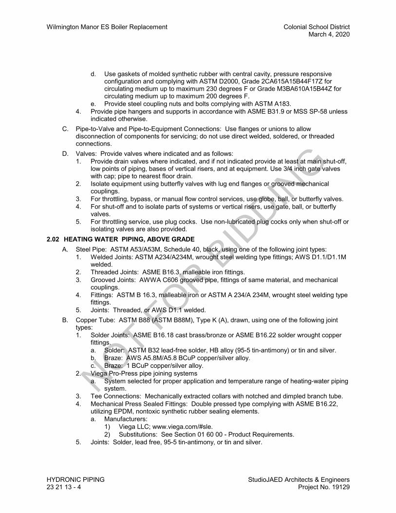
Wilmington Manor ES Boiler Replacement Colonial School DistrictMarch 4, 2020
HYDRONIC PIPING StudioJAED Architects & Engineers23 21 13 - 4 Project No. 19129
d. Use gaskets of molded synthetic rubber with central cavity, pressure responsiveconfiguration and complying with ASTM D2000, Grade 2CA615A15B44F17Z forcirculating medium up to maximum 230 degrees F or Grade M3BA610A15B44Z forcirculating medium up to maximum 200 degrees F.
e. Provide steel coupling nuts and bolts complying with ASTM A183.4. Provide pipe hangers and supports in accordance with ASME B31.9 or MSS SP-58 unless
indicated otherwise.C. Pipe-to-Valve and Pipe-to-Equipment Connections: Use flanges or unions to allow
disconnection of components for servicing; do not use direct welded, soldered, or threadedconnections.
D. Valves: Provide valves where indicated and as follows:1. Provide drain valves where indicated, and if not indicated provide at least at main shut-off,
low points of piping, bases of vertical risers, and at equipment. Use 3/4 inch gate valveswith cap; pipe to nearest floor drain.
2. Isolate equipment using butterfly valves with lug end flanges or grooved mechanicalcouplings.
3. For throttling, bypass, or manual flow control services, use globe, ball, or butterfly valves.4. For shut-off and to isolate parts of systems or vertical risers, use gate, ball, or butterfly
valves.5. For throttling service, use plug cocks. Use non-lubricated plug cocks only when shut-off or
isolating valves are also provided.2.02 HEATING WATER PIPING, ABOVE GRADE
A. Steel Pipe: ASTM A53/A53M, Schedule 40, black, using one of the following joint types:1. Welded Joints: ASTM A234/A234M, wrought steel welding type fittings; AWS D1.1/D1.1M
welded.2. Threaded Joints: ASME B16.3, malleable iron fittings.3. Grooved Joints: AWWA C606 grooved pipe, fittings of same material, and mechanical
couplings.4. Fittings: ASTM B 16.3, malleable iron or ASTM A 234/A 234M, wrought steel welding type
fittings.5. Joints: Threaded, or AWS D1.1 welded.
B. Copper Tube: ASTM B88 (ASTM B88M), Type K (A), drawn, using one of the following jointtypes:1. Solder Joints: ASME B16.18 cast brass/bronze or ASME B16.22 solder wrought copper
fittings.a. Solder: ASTM B32 lead-free solder, HB alloy (95-5 tin-antimony) or tin and silver.b. Braze: AWS A5.8M/A5.8 BCuP copper/silver alloy.c. Braze: 1 BCuP copper/silver alloy.
2. Viega Pro-Press pipe joining systemsa. System selected for proper application and temperature range of heating-water piping
system.3. Tee Connections: Mechanically extracted collars with notched and dimpled branch tube.4. Mechanical Press Sealed Fittings: Double pressed type complying with ASME B16.22,
utilizing EPDM, nontoxic synthetic rubber sealing elements.a. Manufacturers:
1) Viega LLC; www.viega.com/#sle.2) Substitutions: See Section 01 60 00 - Product Requirements.
5. Joints: Solder, lead free, 95-5 tin-antimony, or tin and silver.
NOT FOR B
IDDIN
G

Colonial School District Wilmington Manor ES Boiler ReplacementMarch 4, 2020
StudioJAED Architects & EngineersProject No. 19129
HYDRONIC PIPING23 21 13 - 5
2.03 EQUIPMENT DRAINS AND OVERFLOWSA. Copper Tube: ASTM B88 (ASTM B88M), Type K (A), drawn; using one of the following joint
types:1. Solder Joints: ASME B16.18 cast brass/bronze or ASME B16.22 solder wrought copper
fittings; ASTM B32 lead-free solder, HB alloy (95-5 tin-antimony) or tin and silver.2. Grooved Joints: AWWA C606 grooved pipe, fittings of same material, and mechanical
couplings.3. Joints: Solder, lead free, ASTM B 32, HB alloy (95-5 tin-antimony), or tin and silver.
B. PVC Pipe: ASTM D1785, Schedule 40, or ASTM D2241, SDR 21 or 26.1. Fittings: ASTM D2466 or D2467, PVC.2. Joints: Solvent welded in accordance with ASTM D2855.
2.04 PIPE HANGERS AND SUPPORTSA. Provide hangers and supports that comply with MSS SP-58.
1. If type of hanger or support for a particular situation is not indicated, select appropriatetype using MSS SP-58 recommendations.
B. Conform to ASME B31.9.C. Hangers for Pipe Sizes 1/2 to 1-1/2 Inch: Malleable iron, adjustable swivel, split ring.D. Hangers for Cold Pipe Sizes 2 Inches and Over: Carbon steel, adjustable, clevis.E. Hangers for Hot Pipe Sizes 2 to 4 Inches: Carbon steel, adjustable, clevis.F. Hangers for Hot Pipe Sizes 6 Inches and Over: Adjustable steel yoke, cast iron roll, double
hanger.G. Multiple or Trapeze Hangers: Steel channels with welded spacers and hanger rods.H. Multiple or Trapeze Hangers for Hot Pipe Sizes 6 Inches and Over: Steel channels with welded
spacers and hanger rods, cast iron roll.I. Wall Support for Pipe Sizes to 3 Inches: Cast iron hook.J. Wall Support for Pipe Sizes 4 Inches and Over: Welded steel bracket and wrought steel clamp.K. Wall Support for Hot Pipe Sizes 6 Inches and Over: Welded steel bracket and wrought steel
clamp with adjustable steel yoke and cast iron roll.L. Vertical Support: Steel riser clamp.M. Floor Support for Cold Pipe: Cast iron adjustable pipe saddle, lock nut, nipple, floor flange, and
concrete pier or steel support.N. Floor Support for Hot Pipe Sizes to 4 Inches: Cast iron adjustable pipe saddle, lock nut, nipple,
floor flange, and concrete pier or steel support.O. Floor Support for Hot Pipe Sizes 6 Inches and Over: Adjustable cast iron roll and stand, steel
screws, and concrete pier or steel support.P. Copper Pipe Support: Carbon steel ring, adjustable, copper plated.Q. Hanger Rods: Mild steel threaded both ends, threaded one end, or continuous threaded.R. Inserts: Malleable iron case of galvanized steel shell and expander plug for threaded
connection with lateral adjustment, top slot for reinforcing rods, lugs for attaching to forms; sizeinserts to suit threaded hanger rods.
2.05 UNIONS, FLANGES, MECHANICAL COUPLINGS, AND DIELECTRIC CONNECTIONSA. Unions for Pipe 2 Inches and Under:
1. Ferrous Piping: 150 psig malleable iron, threaded.2. Copper Pipe: Bronze, soldered joints.
NOT FOR B
IDDIN
G
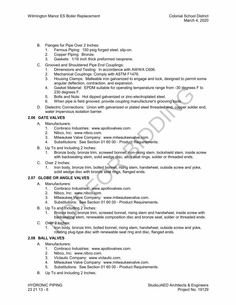
Wilmington Manor ES Boiler Replacement Colonial School DistrictMarch 4, 2020
HYDRONIC PIPING StudioJAED Architects & Engineers23 21 13 - 6 Project No. 19129
B. Flanges for Pipe Over 2 Inches:1. Ferrous Piping: 150 psig forged steel, slip-on.2. Copper Piping: Bronze.3. Gaskets: 1/16 inch thick preformed neoprene.
C. Grooved and Shouldered Pipe End Couplings:1. Dimensions and Testing: In accordance with AWWA C606.2. Mechanical Couplings: Comply with ASTM F1476.3. Housing Clamps: Malleable iron galvanized to engage and lock, designed to permit some
angular deflection, contraction, and expansion.4. Gasket Material: EPDM suitable for operating temperature range from -30 degrees F to
230 degrees F.5. Bolts and Nuts: Hot dipped galvanized or zinc-electroplated steel.6. When pipe is field grooved, provide coupling manufacturer's grooving tools.
D. Dielectric Connections: Union with galvanized or plated steel threaded end, copper solder end,water impervious isolation barrier.
2.06 GATE VALVESA. Manufacturers:
1. Conbraco Industries: www.apollovalves.com.2. Nibco, Inc: www.nibco.com.3. Milwaukee Valve Company: www.milwaukeevalve.com.4. Substitutions: See Section 01 60 00 - Product Requirements.
B. Up To and Including 2 Inches:1. Bronze body, bronze trim, screwed bonnet, non-rising stem, lockshield stem, inside screw
with backseating stem, solid wedge disc, alloy seat rings, solder or threaded ends.C. Over 2 Inches:
1. Iron body, bronze trim, bolted bonnet, rising stem, handwheel, outside screw and yoke,solid wedge disc with bronze seat rings, flanged ends.
2.07 GLOBE OR ANGLE VALVESA. Manufacturers:
1. Conbraco Industries: www.apollovalves.com.2. Nibco, Inc: www.nibco.com.3. Milwaukee Valve Company: www.milwaukeevalve.com.4. Substitutions: See Section 01 60 00 - Product Requirements.
B. Up To and Including 2 Inches:1. Bronze body, bronze trim, screwed bonnet, rising stem and handwheel, inside screw with
backseating stem, renewable composition disc and bronze seat, solder or threaded ends.C. Over 2 Inches:
1. Iron body, bronze trim, bolted bonnet, rising stem, handwheel, outside screw and yoke,rotating plug-type disc with renewable seat ring and disc, flanged ends.
2.08 BALL VALVESA. Manufacturers:
1. Conbraco Industries: www.apollovalves.com.2. Nibco, Inc: www.nibco.com.3. Victaulic Company: www.victaulic.com.4. Milwaukee Valve Company: www.milwaukeevalve.com.5. Substitutions: See Section 01 60 00 - Product Requirements.
B. Up To and Including 2 Inches:
NOT FOR B
IDDIN
G

Colonial School District Wilmington Manor ES Boiler ReplacementMarch 4, 2020
StudioJAED Architects & EngineersProject No. 19129
HYDRONIC PIPING23 21 13 - 7
1. Bronze one piece body, chrome plated brass ball, teflon seats and stuffing box ring, leverhandle with balancing stops, solder ends with union.
C. Over 2 Inches:1. Cast steel body, chrome plated steel ball, teflon seat and stuffing box seals, lever handle,
flanged.2.09 PLUG VALVES
A. Manufacturers:1. Conbraco Industries: www.apollovalves.com.2. Nibco, Inc: www.nibco.com.3. Victaulic Company: www.victaulic.com.4. Milwaukee Valve Company: www.milwaukeevalve.com.5. Substitutions: See Section 01 60 00 - Product Requirements.
B. Up To and Including 2 Inches:1. Bronze body, bronze tapered plug, 40 percent port opening, non-lubricated, teflon packing,
threaded ends.2. Operator: One plug valve wrench for every ten plug valves minimum of one.
C. Over 2 Inches:1. Cast iron body and plug, 40 percent port opening, pressure lubricated, teflon packing,
flanged ends.2. Operator: Each plug valve with a wrench with set screw.
2.10 BUTTERFLY VALVESA. Manufacturers:
1. Hammond Valve: www.hammondvalve.com.2. Crane Co.: www.cranevalve.com.3. Victaulic Company: www.victaulic.com.4. Milwaukee Valve Company: www.milwaukeevalve.com.5. Substitutions: See Section 01 60 00 - Product Requirements.
B. Body: Cast or ductile iron with resilient replaceable EPDM seat, wafer, lug, or grooved ends,extended neck.
C. Disc: Construct of aluminum bronze, chrome plated ductile iron, stainless steel, ductile iron withEPDM enscapsulation, or Buna-N enscapsulation.
D. Body: Cast or ductile iron with resilient replaceable EPDM seat, wafer or lug ends, extendedneck.
E. Disc: Aluminum bronze.F. Operator: Infinite position lever handle with memory stop.
2.11 SWING CHECK VALVESA. Manufacturers:
1. Hammond Valve: www.hammondvalve.com.2. Nibco, Inc: www.nibco.com.3. Victaulic Company: www.victaulic.com.4. Milwaukee Valve Company: www.milwaukeevalve.com.5. Substitutions: See Section 01 60 00 - Product Requirements.
B. Up To and Including 2 Inches:1. Bronze body, bronze trim, bronze rotating swing disc, with composition disc, solder or
threaded ends.C. Over 2 Inches:
NOT FOR B
IDDIN
G
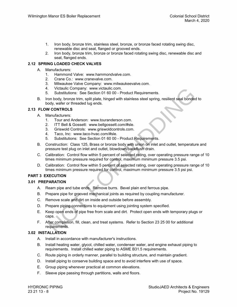
Wilmington Manor ES Boiler Replacement Colonial School DistrictMarch 4, 2020
HYDRONIC PIPING StudioJAED Architects & Engineers23 21 13 - 8 Project No. 19129
1. Iron body, bronze trim, stainless steel, bronze, or bronze faced rotating swing disc,renewable disc and seat, flanged or grooved ends.
2. Iron body, bronze trim, bronze or bronze faced rotating swing disc, renewable disc andseat, flanged ends.
2.12 SPRING LOADED CHECK VALVESA. Manufacturers:
1. Hammond Valve: www.hammondvalve.com.2. Crane Co.: www.cranevalve.com.3. Milwaukee Valve Company: www.milwaukeevalve.com.4. Victaulic Company: www.victaulic.com.5. Substitutions: See Section 01 60 00 - Product Requirements.
B. Iron body, bronze trim, split plate, hinged with stainless steel spring, resilient seal bonded tobody, wafer or threaded lug ends.
2.13 FLOW CONTROLSA. Manufacturers:
1. Tour and Anderson: www.touranderson.com.2. ITT Bell & Gossett: www.bellgossett.com/#sle.3. Griswold Controls: www.griswoldcontrols.com.4. Taco, Inc: www.taco-hvac.com/#sle.5. Substitutions: See Section 01 60 00 - Product Requirements.
B. Construction: Class 125, Brass or bronze body with union on inlet and outlet, temperature andpressure test plug on inlet and outlet, blowdown/backflush drain.
C. Calibration: Control flow within 5 percent of selected rating, over operating pressure range of 10times minimum pressure required for control, maximum minimum pressure 3.5 psi.
D. Calibration: Control flow within 5 percent of selected rating, over operating pressure range of 10times minimum pressure required for control, maximum minimum pressure 3.5 psi psi.
PART 3 EXECUTION3.01 PREPARATION
A. Ream pipe and tube ends. Remove burrs. Bevel plain end ferrous pipe.B. Prepare pipe for grooved mechanical joints as required by coupling manufacturer.C. Remove scale and dirt on inside and outside before assembly.D. Prepare piping connections to equipment using jointing system specified.E. Keep open ends of pipe free from scale and dirt. Protect open ends with temporary plugs or
caps.F. After completion, fill, clean, and treat systems. Refer to Section 23 25 00 for additional
requirements.3.02 INSTALLATION
A. Install in accordance with manufacturer's instructions.B. Install heating water, glycol, chilled water, condenser water, and engine exhaust piping to
requirements. Install chilled water piping to ASME B31.5 requirements.C. Route piping in orderly manner, parallel to building structure, and maintain gradient.D. Install piping to conserve building space and to avoid interfere with use of space.E. Group piping whenever practical at common elevations.F. Sleeve pipe passing through partitions, walls and floors.
NOT FOR B
IDDIN
G
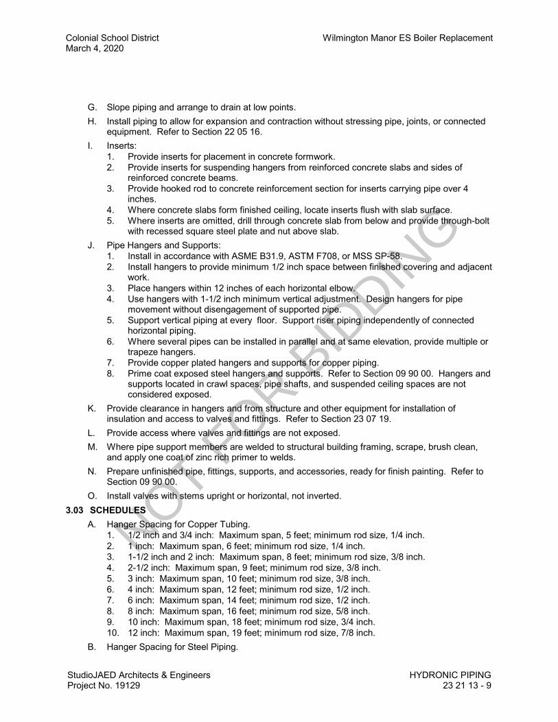
Colonial School District Wilmington Manor ES Boiler ReplacementMarch 4, 2020
StudioJAED Architects & EngineersProject No. 19129
HYDRONIC PIPING23 21 13 - 9
G. Slope piping and arrange to drain at low points.H. Install piping to allow for expansion and contraction without stressing pipe, joints, or connected
equipment. Refer to Section 22 05 16.I. Inserts:
1. Provide inserts for placement in concrete formwork.2. Provide inserts for suspending hangers from reinforced concrete slabs and sides of
reinforced concrete beams.3. Provide hooked rod to concrete reinforcement section for inserts carrying pipe over 4
inches.4. Where concrete slabs form finished ceiling, locate inserts flush with slab surface.5. Where inserts are omitted, drill through concrete slab from below and provide through-bolt
with recessed square steel plate and nut above slab.J. Pipe Hangers and Supports:
1. Install in accordance with ASME B31.9, ASTM F708, or MSS SP-58.2. Install hangers to provide minimum 1/2 inch space between finished covering and adjacent
work.3. Place hangers within 12 inches of each horizontal elbow.4. Use hangers with 1-1/2 inch minimum vertical adjustment. Design hangers for pipe
movement without disengagement of supported pipe.5. Support vertical piping at every floor. Support riser piping independently of connected
horizontal piping.6. Where several pipes can be installed in parallel and at same elevation, provide multiple or
trapeze hangers.7. Provide copper plated hangers and supports for copper piping.8. Prime coat exposed steel hangers and supports. Refer to Section 09 90 00. Hangers and
supports located in crawl spaces, pipe shafts, and suspended ceiling spaces are notconsidered exposed.
K. Provide clearance in hangers and from structure and other equipment for installation ofinsulation and access to valves and fittings. Refer to Section 23 07 19.
L. Provide access where valves and fittings are not exposed. M. Where pipe support members are welded to structural building framing, scrape, brush clean,
and apply one coat of zinc rich primer to welds.N. Prepare unfinished pipe, fittings, supports, and accessories, ready for finish painting. Refer to
Section 09 90 00.O. Install valves with stems upright or horizontal, not inverted.
3.03 SCHEDULESA. Hanger Spacing for Copper Tubing.
1. 1/2 inch and 3/4 inch: Maximum span, 5 feet; minimum rod size, 1/4 inch.2. 1 inch: Maximum span, 6 feet; minimum rod size, 1/4 inch.3. 1-1/2 inch and 2 inch: Maximum span, 8 feet; minimum rod size, 3/8 inch.4. 2-1/2 inch: Maximum span, 9 feet; minimum rod size, 3/8 inch.5. 3 inch: Maximum span, 10 feet; minimum rod size, 3/8 inch.6. 4 inch: Maximum span, 12 feet; minimum rod size, 1/2 inch.7. 6 inch: Maximum span, 14 feet; minimum rod size, 1/2 inch.8. 8 inch: Maximum span, 16 feet; minimum rod size, 5/8 inch.9. 10 inch: Maximum span, 18 feet; minimum rod size, 3/4 inch.10. 12 inch: Maximum span, 19 feet; minimum rod size, 7/8 inch.
B. Hanger Spacing for Steel Piping.
NOT FOR B
IDDIN
G
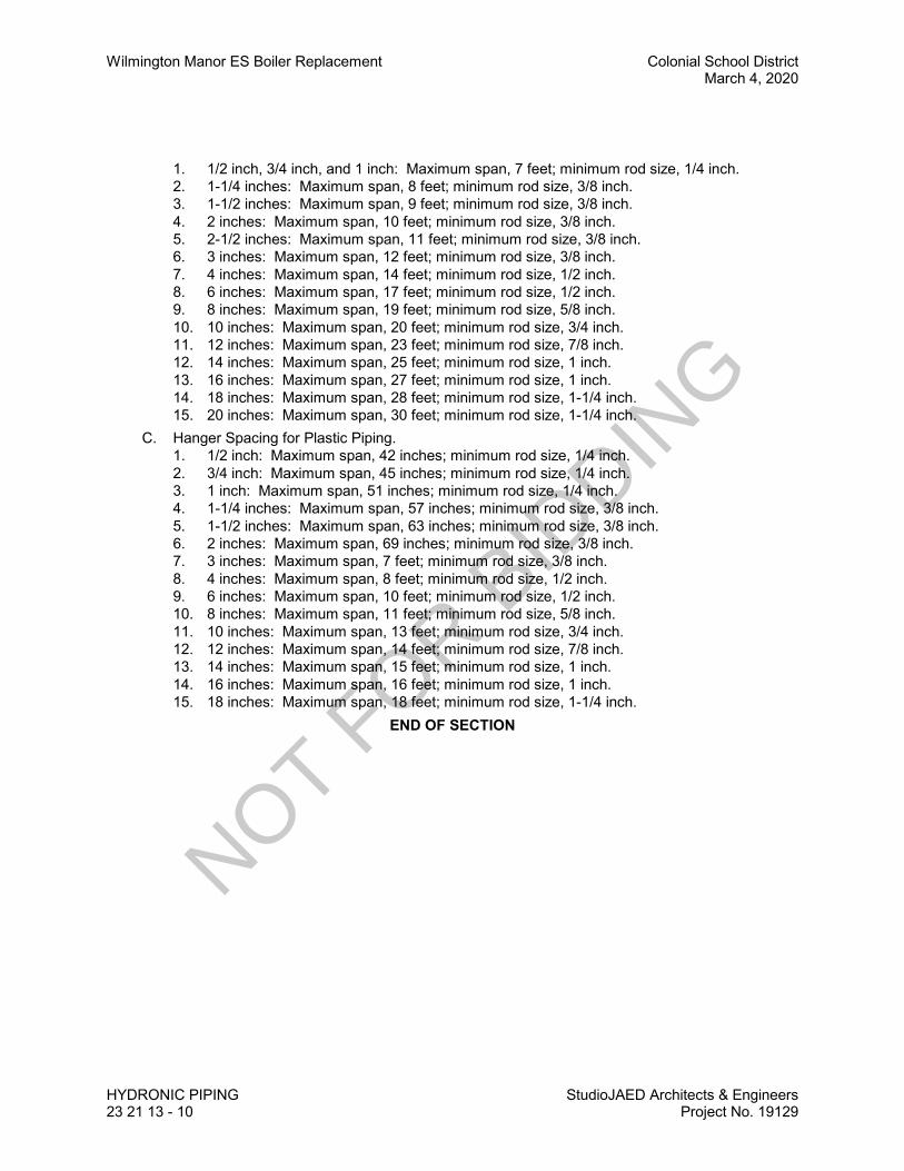
Wilmington Manor ES Boiler Replacement Colonial School DistrictMarch 4, 2020
HYDRONIC PIPING StudioJAED Architects & Engineers23 21 13 - 10 Project No. 19129
1. 1/2 inch, 3/4 inch, and 1 inch: Maximum span, 7 feet; minimum rod size, 1/4 inch.2. 1-1/4 inches: Maximum span, 8 feet; minimum rod size, 3/8 inch.3. 1-1/2 inches: Maximum span, 9 feet; minimum rod size, 3/8 inch.4. 2 inches: Maximum span, 10 feet; minimum rod size, 3/8 inch.5. 2-1/2 inches: Maximum span, 11 feet; minimum rod size, 3/8 inch.6. 3 inches: Maximum span, 12 feet; minimum rod size, 3/8 inch.7. 4 inches: Maximum span, 14 feet; minimum rod size, 1/2 inch.8. 6 inches: Maximum span, 17 feet; minimum rod size, 1/2 inch.9. 8 inches: Maximum span, 19 feet; minimum rod size, 5/8 inch.10. 10 inches: Maximum span, 20 feet; minimum rod size, 3/4 inch.11. 12 inches: Maximum span, 23 feet; minimum rod size, 7/8 inch.12. 14 inches: Maximum span, 25 feet; minimum rod size, 1 inch.13. 16 inches: Maximum span, 27 feet; minimum rod size, 1 inch.14. 18 inches: Maximum span, 28 feet; minimum rod size, 1-1/4 inch.15. 20 inches: Maximum span, 30 feet; minimum rod size, 1-1/4 inch.
C. Hanger Spacing for Plastic Piping.1. 1/2 inch: Maximum span, 42 inches; minimum rod size, 1/4 inch.2. 3/4 inch: Maximum span, 45 inches; minimum rod size, 1/4 inch.3. 1 inch: Maximum span, 51 inches; minimum rod size, 1/4 inch.4. 1-1/4 inches: Maximum span, 57 inches; minimum rod size, 3/8 inch.5. 1-1/2 inches: Maximum span, 63 inches; minimum rod size, 3/8 inch.6. 2 inches: Maximum span, 69 inches; minimum rod size, 3/8 inch.7. 3 inches: Maximum span, 7 feet; minimum rod size, 3/8 inch.8. 4 inches: Maximum span, 8 feet; minimum rod size, 1/2 inch.9. 6 inches: Maximum span, 10 feet; minimum rod size, 1/2 inch.10. 8 inches: Maximum span, 11 feet; minimum rod size, 5/8 inch.11. 10 inches: Maximum span, 13 feet; minimum rod size, 3/4 inch.12. 12 inches: Maximum span, 14 feet; minimum rod size, 7/8 inch.13. 14 inches: Maximum span, 15 feet; minimum rod size, 1 inch.14. 16 inches: Maximum span, 16 feet; minimum rod size, 1 inch.15. 18 inches: Maximum span, 18 feet; minimum rod size, 1-1/4 inch.
END OF SECTION
NOT FOR B
IDDIN
G

Colonial School District Wilmington Manor ES Boiler ReplacementMarch 4, 2020
StudioJAED Architects & EngineersProject No. 19129
HYDRONIC SPECIALTIES23 21 14 - 1
SECTION 23 21 14HYDRONIC SPECIALTIES
PART 1 GENERAL1.01 SECTION INCLUDES
A. Air vents.B. Strainers.C. Suction diffusers.D. Combination pump discharge valves.E. Combination flow controls.F. Pump suction fittings.G. Combination fittings.H. Flow indicators and controls.I. Relief valves.
1.02 RELATED REQUIREMENTSA. Section 23 21 13 - Hydronic Piping.
1.03 SUBMITTALSA. See Section 01 30 00 - Administrative Requirements, for submittal procedures.B. Product Data: Provide product data for manufactured products and assemblies required for this
project. Include component sizes, rough-in requirements, service sizes, and finishes. Includeproduct description, model and dimensions.
C. Certificates: Inspection certificates for pressure vessels from authority having jurisdiction.D. Manufacturer's Installation Instructions: Indicate hanging and support methods, joining
procedures.E. Project Record Documents: Record actual locations of flow controls.F. Maintenance Data: Include installation instructions, assembly views, lubrication instructions,
and replacement parts list.1.04 QUALITY ASSURANCE
A. Manufacturer Qualifications: Company specializing in manufacturing the type of productsspecified in this section, with minimum three years of documented experience.
1.05 DELIVERY, STORAGE, AND HANDLINGA. Accept valves on site in shipping containers with labeling in place. Inspect for damage.B. Provide temporary end caps and closures on piping and fittings. Maintain in place until
installation.C. Protect piping systems from entry of foreign materials by temporary covers, completing sections
of the work, and isolating parts of completed system.PART 2 PRODUCTS2.01 AIR VENTS
A. Manufacturers:1. Armstrong International, Inc: www.armstronginternational.com/#sle.2. ITT Bell & Gossett: www.bellgossett.com/#sle.3. Taco, Inc: www.taco-hvac.com/#sle.4. Substitutions: See Section 01 60 00 - Product Requirements.
NOT FOR B
IDDIN
G

Wilmington Manor ES Boiler Replacement Colonial School DistrictMarch 4, 2020
HYDRONIC SPECIALTIES StudioJAED Architects & Engineers23 21 14 - 2 Project No. 19129
B. Manual Type: Short vertical sections of 2 inch diameter pipe to form air chamber, with 1/8 inchbrass needle valve at top of chamber.
C. Float Type:1. Brass or semi-steel body, copper, polypropylene, or solid non-metallic float, stainless steel
valve and valve seat; suitable for system operating temperature and pressure; withisolating valve.
2. Cast iron body and cover, float, bronze pilot valve mechanism suitable for systemoperating temperature and pressure; with isolating valve.
D. Washer Type:1. Brass with hygroscopic fiber discs, vent ports, adjustable cap for manual shut-off, and
integral spring loaded ball check valve.2.02 STRAINERS
A. Manufacturers:1. Armstrong International, Inc: www.armstronginternational.com/#sle.2. Green Country Filtration: greencountryfiltration.com.3. WEAMCO: www.weamco.com.4. Substitutions: See Section 01 60 00 - Product Requirements.
B. Size 2 inch and Under:1. Screwed brass or iron body for 175 psi working pressure, Y pattern with 1/32 inch stainless
steel perforated screen.C. Size 2-1/2 inch to 4 inch:
1. Flanged iron body for 175 psi working pressure, Y pattern with 3/64 inch stainless steelperforated screen.
D. Size 5 inch and Larger:1. Flanged iron body for 175 psi working pressure, basket pattern with 1/8 inch stainless steel
perforated screen.2.03 SUCTION DIFFUSERS
A. Manufacturers:1. ITT Bell & Gossett: www.bellgossett.com/#sle.2. Anvil International, Inc: www.anvilintl.com.3. Substitutions: See Section 01 60 00 - Product Requirements.
B. Fitting: Angle pattern, cast-iron body, threaded for 2 inch and smaller, flanged for 2-1/2 inchand larger, rated for 175 psi working pressure, with inlet vanes, cylinder strainer with 3/16 inchdiameter openings, disposable 5/32 inch mesh strainer to fit over cylinder strainer, 20 meshstart up screen, and permanent magnet located in flow stream and removable for cleaning.
C. Fitting: Angle pattern, cast-iron body, threaded for 2 inch and smaller, flanged for 2-1/2 inchand larger, rated for 175 psi working pressure, with inlet vanes, cylinder strainer with 3/16 inchdiameter openings, disposable fine mesh strainer to fit over cylinder strainer, and permanentmagnet located in flow stream and removable for cleaning.
D. Accessories: Adjustable foot support, blowdown tapping in bottom, gage tapping in side.2.04 COMBINATION PUMP DISCHARGE VALVES
A. Manufacturers:1. Crane Co.: www.cranevalve.com/#sle.2. Taco, Inc: www.taco-hvac.com/#sle.3. Substitutions: See Section 01 60 00 - Product Requirements.
NOT FOR B
IDDIN
G

Colonial School District Wilmington Manor ES Boiler ReplacementMarch 4, 2020
StudioJAED Architects & EngineersProject No. 19129
HYDRONIC SPECIALTIES23 21 14 - 3
B. Valves: Straight or angle pattern, flanged cast-iron valve body with bolt-on bonnet for 175 psioperating pressure, non-slam check valve with spring-loaded bronze disc and seat, stainlesssteel stem, and calibrated adjustment permitting flow regulation.
2.05 COMBINATION FLOW CONTROLSA. Manufacturers:
1. Amtrol Inc: www.amtrol.com.2. ITT Bell & Gossett: www.bellgossett.com/#sle.3. Tour & Anderson: www.tahydronics.com4. Substitutions: See Section 01 60 00 - Product Requirements.
B. Construction: Brass or bronze body with union on inlet and outlet, temperature and pressuretest plug on inlet and outlet with blowdown/backflush drain.
C. Calibration: Control flow within 5 percent of selected rating, over operating pressure range of 10times minimum pressure required for control, maximum minimum pressure 3.5 psi.
D. Control Mechanism: Stainless steel or nickel plated brass piston or regulator cup, operatingagainst stainless steel helical or wave formed spring.
E. Accessories: In-line strainer on inlet and ball valve on outlet.2.06 RELIEF VALVES
A. Manufacturers:1. Armstrong International, Inc: www.armstronginternational.com/#sle.2. ITT Bell & Gossett: www.bellgossett.com/#sle.3. Conbraco Industries: www.apollovalves.com.4. Substitutions: See Section 01 60 00 - Product Requirements.
B. Bronze body, teflon seat, stainless steel stem and springs, automatic, direct pressure actuated,capacities ASME certified and labelled.
PART 3 EXECUTION3.01 INSTALLATION
A. Install specialties in accordance with manufacturer's instructions.B. Where large air quantities can accumulate, provide enlarged air collection standpipes.C. Provide manual air vents at system high points and as indicated.D. For automatic air vents in ceiling spaces or other concealed locations, provide vent tubing to
nearest drain.E. Provide pump suction fitting on suction side of base mounted centrifugal pumps . Remove
temporary strainers after cleaning systems.F. Provide combination pump discharge valve on discharge side of base mounted centrifugal
pumps .G. Support pump fittings with floor mounted pipe and flange supports.H. Provide relief valves on pressure tanks, low pressure side of reducing valves, heat exchangers,
and expansion tanks.I. Select system relief valve capacity so that it is greater than make-up pressure reducing valve
capacity. Select equipment relief valve capacity to exceed rating of connected equipment.J. Pipe relief valve outlet to nearest floor drain.K. Where one line vents several relief valves, make cross sectional area equal to sum of individual
vent areas.END OF SECTION
NOT FOR B
IDDIN
G

NOT FOR B
IDDIN
G
Colonial School District Wilmington Manor ES Boiler ReplacementMarch 4, 2020
StudioJAED Architects & EngineersProject No. 19129
HYDRONIC PUMPS23 21 23 - 1
SECTION 23 21 23HYDRONIC PUMPS
PART 1 GENERAL1.01 SECTION INCLUDES
A. In-line circulators.B. Base-mounted pumps.
1.02 RELATED REQUIREMENTSA. Section 23 07 16 - HVAC Equipment Insulation.B. Section 23 07 19 - HVAC Piping Insulation.C. Section 23 21 13 - Hydronic Piping.D. Section 23 21 14 - Hydronic Specialties.E. Section 26 27 17 - Equipment Wiring: Electrical characteristics and wiring connections.
1.03 REFERENCE STANDARDSA. NFPA 70 - National Electrical Code.B. UL 778 - Standard for Motor-Operated Water Pumps.
1.04 PERFORMANCE REQUIREMENTSA. Ensure pumps operate at specified system fluid temperatures without vapor binding and
cavitation, are non-overloading in parallel or individual operation, and operate within 25 percentof midpoint of published maximum efficiency curve.
1.05 SUBMITTALSA. See Section 01 30 00 - Administrative Requirements, for submittal procedures.B. Product Data: Provide certified pump curves showing performance characteristics with pump
and system operating point plotted. Include NPSH curve when applicable. Include electricalcharacteristics and connection requirements.
C. Manufacturer's Installation Instructions: Indicate hanging and support requirements andrecommendations.
D. Millwright's Certificate: Certify that base mounted pumps have been aligned.E. Operation and Maintenance Data: Include installation instructions, assembly views, lubrication
instructions, and replacement parts list.F. Maintenance Materials: Furnish the following for Owner's use in maintenance of project.
1. See Section 01 60 00 - Product Requirements, for additional provisions.2. Extra Pump Seals: One set for each type and size of pump.
1.06 QUALITY ASSURANCEA. Manufacturer Qualifications: Company specializing in manufacture, assembly, and field
performance of pumps, with minimum three years of documented experience.B. Alignment: Base mounted pumps shall be aligned by qualified millwright.
1.07 REGULATORY REQUIREMENTSA. Products Requiring Electrical Connection: Listed and classified by UL 778 as suitable for the
purpose specified and indicated.PART 2 PRODUCTS2.01 MANUFACTURERS
A. Armstrong Pumps Inc: www.armstrongpumps.com/#sle.
NOT FOR B
IDDIN
G

Wilmington Manor ES Boiler Replacement Colonial School DistrictMarch 4, 2020
HYDRONIC PUMPS StudioJAED Architects & Engineers23 21 23 - 2 Project No. 19129
B. ITT Bell & Gossett: www.bellgossett.com/#sle.C. Taco: www.taco-hvac.com.D. Substitutions: See Section 01 60 00 - Product Requirements.
2.02 HVAC PUMPS - GENERALA. Provide pumps that operate at specified system fluid temperatures without vapor binding and
cavitation, are non-overloading in parallel or individual operation, and operate within 25 percentof midpoint of published maximum efficiency curve.
B. Products Requiring Electrical Connection: Listed and classified by UL or testing agencyacceptable to authority having jurisdiction as suitable for the purpose specified and indicated.
2.03 IN-LINE CIRCULATORSA. Type: Horizontal shaft, single stage, direct connected, with resiliently mounted motor for in-line
mounting, oil lubricated, for 175 psi maximum working pressure.B. Casing: Cast iron, with flanged pump connections.C. Impeller: Non-ferrous keyed to shaft.D. Bearings: Oil-lubricated bronze sleeve.E. Shaft: Alloy steel with bronze sleeve, integral thrust collar.F. Seal: Mechanical seal, 225 degrees F maximum continuous operating temperature.G. Drive: Flexible coupling.
2.04 BASE MOUNTED PUMPSA. Casing: Cast iron, with suction and discharge gage ports, renewable bronze casing wearing
rings, seal flush connection, drain plug, flanged suction and discharge.B. Impeller: Bronze, fully enclosed, keyed to shaft.C. Bearings: Oil lubricated roller or ball bearings.D. Shaft: Alloy steel with copper, bronze, or stainless steel shaft sleeve.E. Seal: Mechanical seal, 225 degrees F maximum continuous operating temperature.F. Drive: Flexible coupling with coupling guard.G. Baseplate: Cast iron or fabricated steel with integral drain rim.H. Performance: see schedule on drawingsI. Electrical Characteristics: see schedule on drawings
1. Refer to Section 26 27 17.2. Wiring Terminations: Provide terminal lugs to match branch circuit conductor quantities,
sizes, and materials indicated. Enclose terminal lugs in terminal box sized to NFPA 70.PART 3 EXECUTION3.01 PREPARATION
A. Verify that electric power is available and of the correct characteristics.3.02 INSTALLATION
A. Install in accordance with manufacturer's instructions.B. Provide access space around pumps for service. Provide no less than minimum space
recommended by manufacturer.C. Decrease from line size with long radius reducing elbows or reducers. Support piping adjacent
to pump such that no weight is carried on pump casings. For close coupled or base mounted
NOT FOR B
IDDIN
G

Colonial School District Wilmington Manor ES Boiler ReplacementMarch 4, 2020
StudioJAED Architects & EngineersProject No. 19129
HYDRONIC PUMPS23 21 23 - 3
pumps, provide supports under elbows on pump suction and discharge line sizes 4 inches andover.
D. Provide line sized shut-off valve and suction diffuser on pump suction, and line sizedcombination pump discharge valve (B&G Triple Duty Valve or approved equal) on pumpdischarge.
E. Provide air cock and drain connection on horizontal pump casings.F. Provide drains for bases and seals, piped to and discharging into floor drains.G. Check, align, and certify alignment of base mounted pumps prior to start-up.H. Install base mounted pumps on existing concrete housekeeping bases, with anchor bolts, set
and level, and grout in place. Provide manufacturer provided spring isolation to support basefrom concrete housekeeping pad.
I. Lubricate pumps before start-up.3.03 SCHEDULES: SEE DRAWINGS FOR SCHEDULES
END OF SECTION
NOT FOR B
IDDIN
G

NOT FOR B
IDDIN
G

Colonial School District Wilmington Manor ES Boiler ReplacementMarch 4, 2020
StudioJAED Architects & EngineersProject No. 19129
HVAC WATER TREATMENT23 25 00 - 1
SECTION 23 25 00HVAC WATER TREATMENT
PART 1 GENERAL1.01 SECTION INCLUDES
A. Cleaning of piping systems.B. Chemical feeder equipment.C. Chemical treatment.
1.02 RELATED REQUIREMENTSA. Section 23 21 13 - Hydronic Piping.B. Section 23 21 14 - Hydronic Specialties.C. Section 23 09 13 - Instrumentation and Control Devices for HVAC.D. Section 26 27 17 - Equipment Wiring: Electrical characteristics and wiring connections.
1.03 SUBMITTALSA. See Section 01 30 00 - Administrative Requirements, for submittal procedures.B. Product Data: Provide chemical treatment materials, chemicals, and equipment including
electrical characteristics and connection requirements.C. Shop Drawings: Indicate system schematic, equipment locations, and controls schematics,
electrical characteristics and connection requirements.D. Manufacturer's Installation Instructions: Indicate placement of equipment in systems, piping
configuration, and connection requirements.E. Manufacturer's Field Reports: Indicate start-up of treatment systems when completed and
operating properly. Indicate analysis of system water after cleaning and after treatment.F. Certificate: Submit certificate of compliance from authority having jurisdiction indicating
approval of chemicals and their proposed disposal.G. Project Record Documents: Record actual locations of equipment and piping, including
sampling points and location of chemical injectors.H. Operation and Maintenance Data: Include data on chemical feed pumps, agitators, and other
equipment including spare parts lists, procedures, and treatment programs. Include step bystep instructions on test procedures including target concentrations.
I. Maintenance Materials: Furnish the following for Owner's use in maintenance of project.1.04 QUALITY ASSURANCE
A. Manufacturer Qualifications: Company specializing in manufacturing the type of productsspecified in this section, with minimum ten years of documented experience. Company shallhave local representatives with water analysis laboratories and full time service personnel.
B. Installer Qualifications: Company specializing in performing the type of work specified in thissection, with minimum five years of documented experience and approved by manufacturer.
1.05 REGULATORY REQUIREMENTSA. Conform to applicable code for addition of non-potable chemicals to building mechanical
systems and to public sewage systems.B. Products Requiring Electrical Connection: Listed and classified by UL as suitable for the
purpose specified and indicated.
NOT FOR B
IDDIN
G

Wilmington Manor ES Boiler Replacement Colonial School DistrictMarch 4, 2020
HVAC WATER TREATMENT StudioJAED Architects & Engineers23 25 00 - 2 Project No. 19129
1.06 MAINTENANCE SERVICEA. Furnish service and maintenance of treatment systems for one year from Date of Substantial
Completion.B. Provide monthly technical service visits to perform field inspections and make water analysis on
site. Detail findings in writing on proper practices, chemical treating requirements, andcorrective actions needed. Submit two copies of field service report after each visit.
C. Provide laboratory and technical assistance services during this maintenance period.D. Include four hour training course for operating personnel, instructing them on installation, care,
maintenance, testing, and operation of water treatment systems. Arrange course at start up ofsystems.
E. Provide on site inspections of equipment during scheduled or emergency shutdown to properlyevaluate success of water treatment program, and make recommendations in writing basedupon these inspections.
1.07 MAINTENANCE MATERIALSA. See Section 01 6000 - Product Requirements, for additional provisions.B. Supply sufficient chemicals for treatment and testing during warranty period.
PART 2 PRODUCTS2.01 MATERIALS
A. System Cleaner:1. Manufacturers:
a. AmSolv/Division of Amrep, Inc: www.amsolv.com/#sle.b. GE Water Technologies: www.gewater.com/#sle.c. Nalco Company: www.nalco.com/#sle.d. Substitutions: See Section 01 60 00 - Product Requirements.
2. Liquid alkaline compound with emulsifying agents and detergents to remove grease andpetroleum products.
3. Biocide chlorine release agents such as sodium hypochlorite or calcium hypochlorite ormicrobiocides such as quarternary ammonia compounds, tributyl tin oxide, methylene bis(thiocyanate).
4. Ensure compatibility of chemicals with aluminum heat exchangers prior to use in thesystem.
B. Closed System Treatment (Water):1. Manufacturers:
a. AmSolv/Division of Amrep, Inc: www.amsolv.com/#sle.b. GE Water Technologies: www.gewater.com/#sle.c. Nalco Company: www.nalco.com/#sle.d. Substitutions: See Section 01 60 00 - Product Requirements.
2. Sequestering agent to reduce deposits and adjust pH; polyphosphate.3. Corrosion inhibitors; boron-nitrite, sodium nitrite and borax, sodium totyltriazole, low
molecular weight polymers, phosphonates, sodium molybdate, or sulphites.4. Conductivity enhancers; phosphates or phosphonates.5. Guarantee compliance with and maintain pH level as required by the manufacturer of the
condensing boilers for use with aluminum heat exchangers.2.02 BY-PASS (POT) FEEDER
A. Manufacturers:1. Griswold Controls: www.griswoldcontrols.com/#sle.2. J. L. Wingert Company: www.jlwingert.com/#sle.
NOT FOR B
IDDIN
G

Colonial School District Wilmington Manor ES Boiler ReplacementMarch 4, 2020
StudioJAED Architects & EngineersProject No. 19129
HVAC WATER TREATMENT23 25 00 - 3
3. Neptune Chemical Pump Company: www.neptune1.com/#sle.4. Substitutions: See Section 01 60 00 - Product Requirements.
B. 6.0 gal quick opening cap for working pressure of 175 psi.PART 3 EXECUTION3.01 PREPARATION
A. Systems shall be operational, filled, started, and vented prior to cleaning. Use water meter torecord capacity in each system.
B. Place terminal control valves in open position during cleaning.C. Verify that electric power is available and of the correct characteristics.
3.02 CLEANING SEQUENCEA. Concentration:
1. As recommended by manufacturer.2. One pound per 100 gallons of water contained in the system.
B. Hot Water Heating Systems and Dual Temperature Systems:1. Apply heat while circulating, slowly raising temperature to 160 degrees F and maintain for
12 hours minimum.2. Remove heat and circulate to 100 degrees F or less; drain systems as quickly as possible
and refill with clean water.3. Circulate for 6 hours at design temperatures, then drain.4. Refill with clean water and repeat until system cleaner is removed.
C. Use neutralizer agents on recommendation of system cleaner supplier and approval ofContruction Manager, Architect or Engineer of Record.
D. Flush open systems with clean water for one hour minimum. Drain completely and refill.E. Remove, clean, and replace strainer screens.F. Inspect, remove sludge, and flush low points with clean water after cleaning process is
completed. Include disassembly of components as required.3.03 INSTALLATION
A. Install in accordance with manufacturer's instructions.3.04 CLOSED SYSTEM TREATMENT
A. Provide one bypass feeder on each system. Install isolating and drain valves and necessarypiping. Install around balancing valve downstream of circulating pumps unless indicatedotherwise.
B. Introduce closed system treatment through bypass feeder when required or indicated by test.C. Provide 3/4 inch water coupon rack around circulating pumps with space for 12 test specimens.
3.05 CLOSEOUT ACTIVITIESA. Training: Train Owner's personnel on operation and maintenance of chemical treatment
system.1. Provide minimum of two hours of instruction for two people.2. Have operation and maintenance data prepared and available for review during training.3. Conduct training using actual equipment after treated system has been put into full
operation.3.06 MAINTENANCE
A. See Section 01 70 00 - Execution Requirements, for additional requirements relating tomaintenance service.
NOT FOR B
IDDIN
G

Wilmington Manor ES Boiler Replacement Colonial School DistrictMarch 4, 2020
HVAC WATER TREATMENT StudioJAED Architects & Engineers23 25 00 - 4 Project No. 19129
B. Perform maintenance work using competent and qualified personnel under the supervision andin the direct employ of the equipment manufacturer or original installer.
C. Provide service and maintenance of treatment systems for one year from Date of SubstantialCompletion.
D. Provide monthly technical service visits to perform field inspections and make water analysis onsite. Detail findings in writing on proper practices, chemical treating requirements, andcorrective actions needed. Submit two copies of field service report after each visit.
E. Provide laboratory and technical assistance services during this maintenance period.F. Provide on site inspections of equipment during scheduled or emergency shutdown to properly
evaluate success of water treatment program, and make recommendations in writing basedupon these inspections.
END OF SECTION
NOT FOR B
IDDIN
G

Colonial School District Wilmington Manor ES Boiler ReplacementMarch 4, 2020
StudioJAED Architects & EngineersProject No. 19129
HVAC POWER VENTILATORS23 34 23 - 1
SECTION 23 34 23HVAC POWER VENTILATORS
PART 1 GENERAL1.01 SECTION INCLUDES
A. Ceiling exhaust fans.1.02 RELATED REQUIREMENTS
A. Section 23 05 13 - Common Motor Requirements for HVAC Equipment.B. Section 23 05 48 - Vibration and Seismic Controls for HVAC Piping Equipment.C. Section 23 33 00 - Air Duct Accessories: Backdraft dampers.D. Section 26 27 17 - Equipment Wiring: Electrical characteristics and wiring connections.
1.03 REFERENCE STANDARDSA. AMCA 99 - Standards Handbook.B. AMCA 204 - Balance Quality and Vibration Levels for Fans.C. AMCA 210 - Laboratory Methods of Testing Fans for Certified Aerodynamic Performance
Rating.D. AMCA (DIR) - [Directory of] Products Licensed Under AMCA International Certified Ratings
Program; Air Movement and Control Association International, Inc..E. AMCA 300 - Reverberant Room Method for Sound Testing of Fans.F. AMCA 301 - Methods for Calculating Fan Sound Ratings from Laboratory Test Data.G. NEMA MG 1 - Motors and Generators.H. NFPA 96 - Standard for Ventilation Control and Fire Protection of Commercial Cooking
Operations.I. UL 705 - Power Ventilators.
1.04 SUBMITTALSA. See Section 01 30 00 - Administrative Requirements, for submittal procedures.B. Product Data: Provide data on fans and accessories including fan curves with specified
operating point clearly plotted, power, RPM, sound power levels at rated capacity, and electricalcharacteristics and connection requirements.
C. Manufacturer's Instructions: Indicate installation instructions.D. Maintenance Data: Include instructions for lubrication, motor and drive replacement, spare
parts list, and wiring diagrams.1.05 QUALITY ASSURANCE
A. Manufacturer Qualifications: Company specializing in manufacturing the type of productsspecified in this section, with minimum 5 years of documented experience.
B. Kitchen Range Hood Exhaust Fans: Comply with requirements of NFPA 96.C. Products Requiring Electrical Connection: Listed and classified by Underwriters Laboratories
Inc. as suitable for the purpose specified and indicated.1.06 FIELD CONDITIONS
A. Permanent ventilators may be used for ventilation during construction only after ductwork isclean, filters are in place, bearings have been lubricated, and fan has been test run underobservation.
NOT FOR B
IDDIN
G

Wilmington Manor ES Boiler Replacement Colonial School DistrictMarch 4, 2020
HVAC POWER VENTILATORS StudioJAED Architects & Engineers23 34 23 - 2 Project No. 19129
1.07 EXTRA MATERIALSA. See Section 01 6000 - Product Requirements, for additional provisions.B. Supply two sets of belts for each fan.
PART 2 PRODUCTS2.01 MANUFACTURERS
A. Greenheck: www.greenheck.com/#sle.B. Loren Cook Company: www.lorencook.com/#sle.C. PennBarry: www.pennbarry.com/#sle.D. American Coolair/ILG: www.coolair.comE. Substitutions: See Section 01 60 00 - Product Requirements.
2.02 POWER VENTILATORS - GENERALA. Static and Dynamically Balanced: AMCA 204 - Balance Quality and Vibration Levels for Fans.B. Performance Ratings: Determined in accordance with AMCA 210 and bearing the AMCA
Certified Rating Seal.C. Sound Ratings: AMCA 301, tested to AMCA 300, and bearing AMCA Certified Sound Rating
Seal.D. Fabrication: Conform to AMCA 99.E. Electrical Components: Listed and classified by Underwriters Laboratories Inc. as suitable for
the purpose specified and indicated.2.03 CABINET AND CEILING EXHAUST FANS
A. Performance: As Indicated on drawings.1. Motor: Refer to Section 23 05 13.
B. Centrifugal Fan Unit: V-belt or direct driven with galvanized steel housing lined with acousticinsulation, resilient mounted motor, gravity backdraft damper in discharge.
C. Disconnect Switch: Cord and plug in housing for thermal overload protected motor .D. Grille: Molded white plastic or Aluminum with baked white enamel finish.E. Sheaves: Cast iron or steel, dynamically balanced, bored to fit shafts and keyed; variable and
adjustable pitch motor sheaves selected so required rpm is obtained with sheaves set atmid-position; fan shaft with self-aligning pre-lubricated ball bearings.
PART 3 EXECUTION3.01 INSTALLATION
A. Install in accordance with manufacturer's instructions.B. Secure roof or wall exhausters with aluminum lag screws to roof curb or structure.C. Extend ducts to roof or wall exhausters into roof curb or structure. Counterflash duct to roof or
wall opening.D. Hung Cabinet Fans:
1. Install fans with resilient mountings and flexible electrical leads. Refer to Section 23 05 48.2. Install flexible connections specified in Section 23 33 00 between fan and ductwork.
Ensure metal bands of connectors are parallel with minimum one inch flex betweenductwork and fan while running.
E. Provide sheaves required for final air balance.F. Install backdraft dampers on inlet to roof and wall exhausters.
NOT FOR B
IDDIN
G

Colonial School District Wilmington Manor ES Boiler ReplacementMarch 4, 2020
StudioJAED Architects & EngineersProject No. 19129
HVAC POWER VENTILATORS23 34 23 - 3
G. Provide backdraft dampers on outlet from cabinet and ceiling exhauster fans and as indicated.END OF SECTION
NOT FOR B
IDDIN
G

NOT FOR B
IDDIN
G

Colonial School District Wilmington Manor ES Boiler ReplacementMarch 4, 2020
StudioJAED Architects & EngineersProject No. 19129
CONDENSING HIGHEFFICIENCY STAINLESS STEEL
FIRETUBE BOILERS23 52 17 - 1
SECTION 23 52 17CONDENSING HIGH EFFICIENCY STAINLESS STEEL FIRETUBE BOILERS
PART 1 - GENERAL1.01 RELATED DOCUMENTS
A. Drawings and general provisions of the Contract, including General and SupplementaryConditions and Division 01 Specification Sections, apply to this Section.
1.02 SUMMARYA. This Section includes gas-fired, condensing stainless steel firetube boilers for heating hot water.
1.03 SUBMITTALSA. Product Data: Include rated capacities; shipping, installed, and operating weights; furnished
specialties; and accessories for each model indicated.B. Shop Drawings: Detail equipment assemblies and indicate dimensions, required clearances,
and method of field assembly, components, and location and size of each field connection.1. Wiring Diagrams: Detail wiring for power, signal, and control systems and differentiate
between manufacturer installed and field installed wiring.C. Source Quality Control Tests and Inspection Reports: Indicate and interpret test results for
compliance with performance requirements before shipping.D. Field Test Reports: Indicate and interpret test results for compliance with performance
requirements.E. Maintenance Data: Include in the maintenance manuals specified in Division 1. Include parts
list, maintenance guide, and wiring diagrams for each boiler.1.04 QUALITY ASSURANCE
A. Listing and Labeling: Provide electrically operated components specified in this Sectionthat are listed and labeled.1. The Terms “Listed” and “Labeled”: As defined in NFPA 70, Article 100.2. Listing and Labeling Agency Qualifications: A “Nationally Recognized Testing Laboratory”
as defined in OSHA Regulation 1910.7.B. ASME Compliance: Boilers shall bear ASME “H” stamp and be National Board listed.C. FM Compliance: Control devices and control sequences according to requirements of FM.D. Comply with NFPA 70 for electrical components and installation.E. IRI Compliance: Control devices and control sequences according to requirements of IRI (GE
GAP).F. CSD-1G. SCAQMD Rule 1146.2 for low NOx equipment
1.05 COORDINATIONA. Coordinate size and location of concrete bases. Concrete, reinforcement, and formwork
requirements are specified in Division 3 Section “Cast-in-Place Concrete.”1.06 WARRANTY
A. General Warranty: The special warranty specified in this Article shall not deprive the Owner ofother rights the Owner may have under other provisions of the Contract Documents and shallbe in addition to, and run concurrent with, other warranties made by the Contractor underrequirements of the Contract Documents. Installing contractor shall provide one year of warrantyparts and labor.
NOT FOR B
IDDIN
G

Wilmington Manor ES Boiler Replacement Colonial School DistrictMarch 4, 2020
CONDENSING HIGH EFFICIENCY STAINLESS STEEL FIRETUBE BOILERSStudioJAED Architects & Engineers23 52 17 - 2 Project No. 19129
B. Special Warranty: Submit a written warranty, executed by the contractor for the heat exchanger.1. Warranty Period: The heat exchanger assembly shall carry a ten (10) year warranty with
an additional twenty one (21) year thermal shock warranty on heat exchanger.PART 2 - PRODUCTS2.01 MANUFACTURERS
A. Available Manufacturers: Manufacturer shall be a company specializing in manufacturing theproducts specified in this section with minimum five (5) years experience. Subject to compliancewith requirements, manufacturers offering boilers that may be incorporated into the Workinclude, but are not limited to, the following:
B. Design: Boilers shall be CSA design certified as a condensing boiler. Boilers shall be designedfor a minimum of 5:1 continuous turn down with constant CO2 over the turndown range. Theboiler shall operate with natural gas and have a CSA International certified input rating as notedon the drawings, and a thermal efficiency rating up to 99% at minimum input. The boiler shall besymmetrically air-fuel coupled such that changes in combustion air flow or flue flows affect theBTUH input without affecting combustion quality. The boiler will automatically adjust input foraltitude and temperature induced changes in air density. The boiler will use a proven pilotinterrupted spark ignition system. The boiler shall use a UL approved flame safeguard ignitioncontrol system using UV detection flame sensing. The UV detector shall be air cooled to preventcondensate formation and so designed as to prevent misalignment. The design shall provide forsilent burner ignition and operation. The boiler shall be down-fired counter-flow such that formedcondensate always moves toward a cooler zone to prevent re-evaporation. A corrosion resistantcondensate drain designed to prevent pooling and accessible condensate trap shall beprovided. In some jurisdictions, a means of neutralizing the condensate pH levels may berequired. Boiler shall be able to vent a horizontal distance of 100 equivalent feet, 30.5m with avent diameter equivalent to the combustion chamber outlet diameter.
C. Service Access: The boilers shall be provided with access covers for easily accessing allserviceable components. The boilers shall not be manufactured with large enclosures, whichare difficult to remove and reinstall. All accesses must seal completely as not to disrupt thesealed combustion process. All components must be accessible and able to adjust with theremoval of a single cover or cabinet component.
D. Indicating lights: Each boiler shall include a diagnostic control panel with a full text displayindicating the condition of all interlocks and the BTUH input percentage. Access to the controlsshall be through a completely removable cover leaving diagnostic panel intact and not disrupted.
E. Manufacturers: RBI (a Mestek Company) is the basis of design. Listed acceptablemanufacturers shall be subject to compliance with requirements. Provide boilers by one of thefollowing:1. Parker2. Aerco - Benchmark
2.02 COMPONENTSA. Combustion Chamber: The combustion chamber shall be constructed of stainless steel. It shall
be a down-fired design.B. Heat Exchanger: Boilers shall be a stainless steel firetube unit designed for pressure firing and
shall be constructed and tested for 160 P.S.I water working pressure and 210°F, 99°Cmaximum operating temperature, in accordance with the A.S.M.E. Section IV Rules for theConstruction of Heating Boilers. The firetubes shall be of a down-fired counter-flow single- passdesign. Stainless steel tubes will be rounded, rectangular tubes with an integral dimpled design.The tube sheet is fully symmetrical and conical in shape to allow it to act as a piston to reducethe intra-tubular stresses. This allows the unit to absorb expansion and contraction evenly
NOT FOR B
IDDIN
G
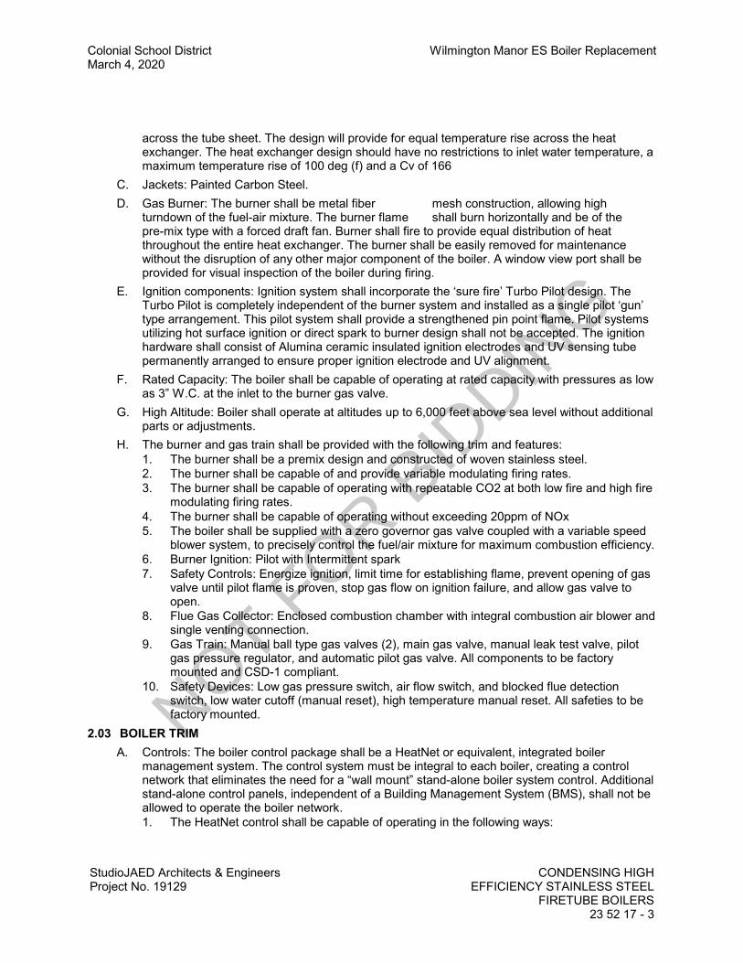
Colonial School District Wilmington Manor ES Boiler ReplacementMarch 4, 2020
StudioJAED Architects & EngineersProject No. 19129
CONDENSING HIGHEFFICIENCY STAINLESS STEEL
FIRETUBE BOILERS23 52 17 - 3
across the tube sheet. The design will provide for equal temperature rise across the heatexchanger. The heat exchanger design should have no restrictions to inlet water temperature, amaximum temperature rise of 100 deg (f) and a Cv of 166
C. Jackets: Painted Carbon Steel.D. Gas Burner: The burner shall be metal fiber mesh construction, allowing high
turndown of the fuel-air mixture. The burner flame shall burn horizontally and be of thepre-mix type with a forced draft fan. Burner shall fire to provide equal distribution of heatthroughout the entire heat exchanger. The burner shall be easily removed for maintenancewithout the disruption of any other major component of the boiler. A window view port shall beprovided for visual inspection of the boiler during firing.
E. Ignition components: Ignition system shall incorporate the ‘sure fire’ Turbo Pilot design. TheTurbo Pilot is completely independent of the burner system and installed as a single pilot ‘gun’type arrangement. This pilot system shall provide a strengthened pin point flame. Pilot systemsutilizing hot surface ignition or direct spark to burner design shall not be accepted. The ignitionhardware shall consist of Alumina ceramic insulated ignition electrodes and UV sensing tubepermanently arranged to ensure proper ignition electrode and UV alignment.
F. Rated Capacity: The boiler shall be capable of operating at rated capacity with pressures as lowas 3” W.C. at the inlet to the burner gas valve.
G. High Altitude: Boiler shall operate at altitudes up to 6,000 feet above sea level without additionalparts or adjustments.
H. The burner and gas train shall be provided with the following trim and features:1. The burner shall be a premix design and constructed of woven stainless steel.2. The burner shall be capable of and provide variable modulating firing rates.3. The burner shall be capable of operating with repeatable CO2 at both low fire and high fire
modulating firing rates.4. The burner shall be capable of operating without exceeding 20ppm of NOx5. The boiler shall be supplied with a zero governor gas valve coupled with a variable speed
blower system, to precisely control the fuel/air mixture for maximum combustion efficiency.6. Burner Ignition: Pilot with Intermittent spark7. Safety Controls: Energize ignition, limit time for establishing flame, prevent opening of gas
valve until pilot flame is proven, stop gas flow on ignition failure, and allow gas valve toopen.
8. Flue Gas Collector: Enclosed combustion chamber with integral combustion air blower andsingle venting connection.
9. Gas Train: Manual ball type gas valves (2), main gas valve, manual leak test valve, pilotgas pressure regulator, and automatic pilot gas valve. All components to be factorymounted and CSD-1 compliant.
10. Safety Devices: Low gas pressure switch, air flow switch, and blocked flue detectionswitch, low water cutoff (manual reset), high temperature manual reset. All safeties to befactory mounted.
2.03 BOILER TRIMA. Controls: The boiler control package shall be a HeatNet or equivalent, integrated boiler
management system. The control system must be integral to each boiler, creating a controlnetwork that eliminates the need for a “wall mount” stand-alone boiler system control. Additionalstand-alone control panels, independent of a Building Management System (BMS), shall not beallowed to operate the boiler network.1. The HeatNet control shall be capable of operating in the following ways:
NOT FOR B
IDDIN
G

Wilmington Manor ES Boiler Replacement Colonial School DistrictMarch 4, 2020
CONDENSING HIGH EFFICIENCY STAINLESS STEEL FIRETUBE BOILERSStudioJAED Architects & Engineers23 52 17 - 4 Project No. 19129
a. As a stand-alone boiler control system using the HeatNet protocol, with one “Master”and multiple “Member” units.
b. As a boiler network, enabled by a Building Management System (BMS), using theHeatNet protocol, with one “Master” and multiple “Member” units.
c. As “Member” boilers to a Building Management System (BMS) with multiple inputcontrol methods.
d. Failsafe mode - When a Building Automation System is controlling set point, ifcommunications are lost, the boiler/ system will run off the Local set point.
e. Adaptive Modulation - Lowers the modulation rate of all currently operating boilersbefore a newly added boiler enters operation.
f. Priority Firing - Allows mixing of condensing, non-condensing base load and/or othercombination of (2) functional boiler types utilizing (2) priority levels.
g. Available priority start/stop qualifiers shall be done using any combination of:A) Modulation Percentage B) Outdoor Air Temperature or C) Return WaterTemperature.
h. Base Loading - Provides the ability to control (1) base load boiler with enable/disableand 4-20mA modulating signal (if required).
2. MASTER: A boiler becomes a Master when a resistance type 10K sensor is connected tothe J10 “SYS/ DHW HEADER” terminals. The sensor shall be auto-detected. The Mastersenses and controls the header/loop temperature utilizing a system set point. It uses anyboilers it finds “HeatNet Members” or those defined in the control setup menus toaccomplish this. The “Master” shall also have the option of monitoring Outside AirTemperature “OA” to provide full outdoor air reset functionality. Only one master shall beallowed in the boiler network.
3. When operating as a “Master”, the HeatNet control provides a stand-alone method using aPID algorithm to regulate water temperature. The algorithm allows a single boiler “Master”or multiple “Master + Member” boilers in a network of up to 16 total boilers.
4. The control algorithm is based upon a control band, at the center of which is the set point.While below the control band, boilers are staged on and modulated up until the controlband is entered. Once in the control band, modulation is used to maintain set point.Optimized system efficiency is always accomplished by setting the Modulation Maximum“Mod-Max” setting to exploit each boiler in the network’s inverse efficiency curve. Thecontrol shall operate so that the maximum number of boilers required, operate at theirlowest inputs until all boilers are firing. Once all boilers are firing, the modulation clamp isremoved and all boilers are allowed to fire above this clamped percentage up to 100%.This “boiler efficiency” clamp is defaulted to 80% and thus limits all the boilers individualoutputs to 80% until the last boiler fires. The 80% default must be field adjustable forvarying operating conditions. All boilers modulate up and down together always at thesame modulation rate. Boilers are shut down only when the top of the band is breached, orbefore the top of the band, if the control anticipates that there is a light load. Timers shallalso be included in each control in the network to prevent any boiler from short cycling.
5. MEMBER: Additional boilers in the network always default to the role of member. The lackof sensors connected to the J10 terminals “SYS/DHW Header” on each additional boilershall ensure this.
6. Each “Member” shall sense its supply outlet water temperature and modulate based onsignals from a Building Management System (BMS) or “Master” boiler. When operating asa member, starting, stopping, and firing rate shall also be controlled by the “BMS” or“Master” boiler.
7. When using the HeatNet protocol, the system setpoint shall be sent from the “Master”,along with the modulation value to control firing rate. It also receives its command to startor stop over the HeatNet cable. Each “Member” will continuously monitor its supply outlettemperature against its operating limit. If the supply temperature approaches the operating
NOT FOR B
IDDIN
G

Colonial School District Wilmington Manor ES Boiler ReplacementMarch 4, 2020
StudioJAED Architects & EngineersProject No. 19129
CONDENSING HIGHEFFICIENCY STAINLESS STEEL
FIRETUBE BOILERS23 52 17 - 5
limit temperature (adjustable), the boilers input control rate is limited and its modulationvalue decreases to minimize short cycling. If the operating limit is exceeded, the boilershall shut off.
8. Each HeatNet control in the boiler network shall have the following standard features:a. Digital Communications Control.
1) Boiler to Boiler: HeatNet2) Building Management System (BMS): MODBUS standard protocol. (BACnet,
LONWORKS and N2 optional protocols)b. Analog 4:20 and 0-10vdc also supported.c. Distributed control using HeatNet protocol for up to 16 total boilers.d. English text display.e. Interlock, Event, and System logging with a time stamp.f. Advanced PID algorithm optimized for FlexCore boilers.g. Four dedicated temperature sensor inputs for: Outside Air Temperature, Supply
(Outlet Temperature, Return Temperature (Inlet)), and Header Temperature.h. Automatically detects the optional temperature sensors on start up.i. Touch Screen Display.j. (8) Dedicated 24vac interlock monitors and 8 dedicated 120vac system monitors used
for diagnostics and providing feedback of faults and system status.k. Multiple boiler pump or motorized boiler valve control modes.l. Combustion Air Damper control with proof time.m. Optional USB/RS485 network plug-in to allow firmware updates or custom
configurations.n. Optional BACnet, LONWORKS and N2 interface.o. Alarm contacts.p. Runtime hours.q. Outdoor Air Reset with programmable ratio.r. Time of Day clock to provide up to four (4) night setback temperatures.s. Failsafe mode when a Building Management System (BMS) is controlling set point. If
communications are lost, the boiler/ system shall run off the Local Set point.t. Support for domestic hot water (DHW) using a 10k sensor or a dry contact input from
a tank thermostat and a domestic hot water relay (pump/valve).u. Continuous Daily Runtime Restart feature that monitors the runtime of each boiler and
if any in the network have exceeded the maximum hours of continuous runtime, theboiler will restart to protect the UV flame scanner.
v. Allows for selection of any boiler in the network to act as Lead Boiler.w. Adaptive Modulation feature in which the Master boiler adjusts the system modulation
rate to a lower value when a new boiler in the network is started to compensate forthe added BTU’s to the system. Once the newly added boiler fires and the adjustabletime expire, the Master resumes control of the system modulation to maintainset-point temperature.
x. Priority firing - Allows mixing of condensing and non-condensing, base load and/orother combination of (2) functional boiler types utilizing (2) priority levels.
y. Available priority start/stop qualifiers shall be done using any combination of:A) modulation percentage, B) outdoor air temperature, (or) C) return watertemperature.
z. Base Loading - Provides the ability to control (1) base load boiler with enable/disableand 4-20mA modulating signal (if required).
aa. Boiler(s) shall be equipped with an integrated web based monitoring system.
NOT FOR B
IDDIN
G

Wilmington Manor ES Boiler Replacement Colonial School DistrictMarch 4, 2020
CONDENSING HIGH EFFICIENCY STAINLESS STEEL FIRETUBE BOILERSStudioJAED Architects & Engineers23 52 17 - 6 Project No. 19129
1) Monitoring system shall provide an email or SMS text message notification upondetecting an out of tolerance condition.
2) The integrated monitoring system shall provide a web portal with performancedashboard displaying key data points for the system and each boiler in thesystem.
3) The web portal shall provide the following capabilities;(a) Detailed status of data points and system set-points(b) Boiler and System runtime and cycle count(c) Intelligent diagnostics and troubleshooting guide(d) Provide original factory test data including as built bill of materials(e) The ability to enter field service records with file upload
capabilities(f) The ability to view time stamped history of data points and settings(g) The ability to view detailed event log entries(h) Video tutorials explaining each section of the web portal
4) The monitoring system shall have the capability of connecting directly to a10/100mbps TCP/IP network Optionally when a facility network connection is notavailable the system shall be capable of utilizing wireless cellular network
5) The monitoring system shall utilize a non-public proprietary data encryptionalgorithm
6) Secure data transmission shall be directly to the cloud from HeatNet enabledsystem(s) without third party integration
B. Safety Relief Valve: ASME rated, factory set to protect boiler and piping as perschedule/drawings. 160 psi maximum allowable working pressure.
C. Gauge: Combination water pressure and temperature shipped factory installed. LCD outlettemperature readout to be an integral part of the front boiler control panel display to allow forconsistent easy monitoring of temperatures factory mounted and wired.
D. Flow Sensor: Boiler shall be provided with a digital flow sensing device integral to the boilercontrol system, mounted in a by-pass and mapped to indicate the boiler flow in (gpm), the flowsensor utilizes vortex technology which is then converted to an electronic signal sent directly tothe Boiler Control System for real time flow annunciation. The set-point is fully adjustablethroughout the boiler model operating range.
E. Burner Controls: Boiler shall be provided with a Honeywell RM7800 series digital flame safeguard with UV rectification. The flame safe guard shall be capable of both pre and post purgecycles.
F. High Limit: Temperature control with manual reset limits boiler water temperature in series withthe operating control. High Limit shall be factory mounted and sense the outlet temperature ofthe boiler through a dry well.
G. PROVIDE THE FOLLOWING STANDARD TRIM:1. Low Air Pressure Switch2. Blocked Flue Switch3. Modulation Control4. Temperature/Pressure Gauge5. Manual Reset High Limit (CSD-1 Factory Mounted and Wired)6. Low Gas Pressure Switch (Above 2500 MBH)7. Low Water Cutoff with Manual Reset (CSD-1 Factory mounted and wired)8. Supply Outlet Temperature Display9. Full Digital Text LCD Touch Screen Display for all Boiler Series of Operation and Failures10. Air Inlet Filter
NOT FOR B
IDDIN
G
Colonial School District Wilmington Manor ES Boiler ReplacementMarch 4, 2020
StudioJAED Architects & EngineersProject No. 19129
CONDENSING HIGHEFFICIENCY STAINLESS STEEL
FIRETUBE BOILERS23 52 17 - 7
11. Combustion Air Fan with Safety Interlock12. Condensate Drain13. High Gas Pressure Switch (Above 2500 MBH)14. Flow Sensor Mounted & Wired15. Relief Valve
H. PROVIDE THE FOLLOWING JOB SPECIFIC TRIM AND FEATURES:1. Valve Proving Switch2. Isolation Valve Wiring3. 208V 3PH4. JJM Boiler Works NB5LP Condensate Neutralizer
2.04 MOTORSA. Boiler Blower Motor: The Blower shall be a variable speed blower.
2.05 SOURCE QUALITY CONTROLA. Test and inspect boilers according to the ASME Boiler and Pressure Vessel Code, Section IV.
Boilers shall be test fired in the factory with a report attached permanently to the exterior cabinetof the boiler for field reference.
PART 3 - EXECUTION3.01 EXAMINATION
A. Examine area to receive boiler for compliance with requirements for installation tolerances andother conditions affecting boiler performance. Do not proceed with installation untilunsatisfactory conditions have been corrected.
3.02 INSTALLATIONA. Install boilers level and plumb, according to manufacturer’s written instructions and referenced
standards.B. Install gas fired boilers according to NFPA 54.C. Support boilers on a minimum 4 inches (100 mm) thick concrete base, 4 inches (100 mm)
larger on each side than base of unit.D. Install electrical devices furnished with boiler, but not specified to be factory mounted.
3.03 CONNECTIONSA. Connect gas piping full size, to boiler gas train inlet with union.B. Connect hot water piping to the inlet and outlet boiler connections with shutoff valve and union
or flange at each connection.C. Install piping from safety relief valves to nearest floor drain.D. Connect breeching to boiler outlet, full size of outlet. The boiler shall operate under positive
(Category IV) or negative (Category II) stack pressure. Vent material must be listed AL29-4CStainless Double Wall Stack for condensing appliances.
E. A vent kit must be supplied by the manufacturer when utilizing the non metallic (PVC, PP)option.
F. Electrical: Comply with applicable requirements in Division 16 Sections.G. Ground equipment.
1. Tighten electrical connectors and terminals according to manufacturer’s published torquetightening values. If manufacturer’s torque values are not indicated, use those specified inUL 486A and UL 486B.
NOT FOR B
IDDIN
G

Wilmington Manor ES Boiler Replacement Colonial School DistrictMarch 4, 2020
CONDENSING HIGH EFFICIENCY STAINLESS STEEL FIRETUBE BOILERSStudioJAED Architects & Engineers23 52 17 - 8 Project No. 19129
3.04 FIELD QUALITY CONTROLA. Manufacturer’s Field Service: Engage a factory authorized service representative to supervise
the field assembly of components and installation of boilers, including piping and electricalconnections. Report results in writing.1. Test and adjust controls and safeties. Replace damaged and malfunctioning controls and
equipment. Boiler shall be commissioned by factory authorized technician. Contact localrepresentative for factory authorized technician information.
B. Manufacturer’s representative shall supply a factory authorized service technician to start up theboilers.
3.05 CLEANINGA. Flush and clean boilers on completion of installation, according to manufacturer’s written
instructions.B. After completing boiler installation, including outlet fittings and devices, inspect exposed finish.
Remove burrs, dirt, and construction debris and repair damaged finishes including chips,scratches, and abrasions with manufacturer’s stainless steel polish.
3.06 COMMISSIONINGA. Engage a factory authorized service representative to provide startup service. Startup to be
performed only after complete boiler room operation is field verified to offer a substantial load,and complete system circulation. One-year warranty shall be handled by factory authorized tech.
B. Verify that installation is as indicated and specified.1. Verify that electrical wiring installation complies with manufacturer’s submittal and
installation requirements in Division 16 Sections. Do not proceed with boiler startup untilwiring installation is acceptable to equipment Installer.
C. Complete manufacturer’s installation and startup checklist and verify the following:1. Boiler is level on concrete base.2. Flue and chimney are installed without visible damage.3. No damage is visible to boiler jacket, refractory, or combustion chamber.4. Pressure reducing valves are checked for correct operation and specified relief pressure.
Adjust as required.5. Clearances have been provided and piping is flanged for easy removal and servicing.6. Heating circuit pipes have been connected to correct ports.7. Labels are clearly visible.8. Boiler, burner, and flue are clean and free of construction debris.9. Pressure and temperature gauges are installed.10. Control installations are completed.
D. Ensure pumps operate properly.E. Check operation of gas pressure regulator device on gas train, including venting.F. Check that fluid level, flow sensor, and high temperature interlocks are in place.G. Start pumps and boilers, and adjust burners to maximum operating efficiency.
1. Fill out startup checklist and attach copy with Contractor Startup Report.2. Check and record performance of factory provided boiler protection devices and firing
sequences.3. Check and record performance of boiler fluid level, flow sensor, and high temperature
interlocks.4. Operate boilers as recommended or required by manufacturer.
NOT FOR B
IDDIN
G

Colonial School District Wilmington Manor ES Boiler ReplacementMarch 4, 2020
StudioJAED Architects & EngineersProject No. 19129
CONDENSING HIGHEFFICIENCY STAINLESS STEEL
FIRETUBE BOILERS23 52 17 - 9
H. Perform the following tests for maximum and minimum firing rates for modulating burner. Adjustboiler combustion efficiency at maximum and minimum modulation rates. Perform combustionflue gas test at minimum and maximum modulation rate. Measure and record the following:1. Differential pressure across air / gas orifice.2. Combustion air temperature at inlet to burner.3. Flue gas temperature at boiler discharge.4. Flue gas carbon dioxide, oxygen, and carbon monoxide concentration.5. Flue gas NOx emissions where applicable.6. Natural flue draft.
I. Measure and record temperature rise through each boiler.J. Provide factory representative to inspect and certify that the boiler is installed and properly
operating in accordance with manufacturer installation instructions and recommendations aswell as in accordance with contract documents. Factory representative shall provde certificationon boiler manufacturer letterhead that states that the boiler is insttalled and operating inaccordance with manufacturer installation instructions and recommendations as well as inaccordance with contract documents. Provide the certification in triplicate to theArchitect/Engineer for review. Architect/Engineer will forward at least one copy to the Owner fortheir records.
3.07 DEMONSTRATION AND TRAININGA. Engage a factory authorized service representative to train Owner’s maintenance personnel as
specified below:1. Operate boiler, including accessories and controls, to demonstrate compliance with
requirements.2. Train Owner’s maintenance personnel on procedures and schedules related to startup and
shutdown, troubleshooting, servicing, and preventive maintenance.3. Review data in the maintenance manuals. Refer to Division 1 Section “Contract Closeout.”4. Review data in the maintenance manuals. Refer to Division 1 Section “Operation and
Maintenance Data.”5. Schedule training with Owner with at least 7 days advance notice.
END OF SECTION
NOT FOR B
IDDIN
G

NOT FOR B
IDDIN
G
Colonial School District Wilmington Manor ES Boiler ReplacementMarch 4, 2020
StudioJAED Architects & EngineersProject No. 19129
MINOR ELECTRICALDEMOLITION
26 05 01 - 1
SECTION 26 05 01MINOR ELECTRICAL DEMOLITION
PART 1 GENERAL1.01 SECTION INCLUDES
A. Electrical demolition.1.02 RELATED REQUIREMENTS
A. Section 01 70 00 - Execution and Closeout Requirements: Additional requirements foralterations work.
PART 2 PRODUCTS2.01 MATERIALS AND EQUIPMENT
A. Materials and equipment for patching and extending work: As specified in individual sections.PART 3 EXECUTION3.01 EXAMINATION
A. Verify field measurements and circuiting arrangements are as shown on Drawings.B. Verify that abandoned wiring and equipment serve only abandoned facilities.C. Demolition drawings are based on casual field observation .D. Report discrepancies to Owner before disturbing existing installation.E. Report discrepancies to Architect before disturbing existing installation.F. Beginning of demolition means installer accepts existing conditions.
3.02 PREPARATIONA. Disconnect electrical systems in walls, floors, and ceilings to be removed.B. Coordinate utility service outages with utility company.C. Provide temporary wiring and connections to maintain existing systems in service during
construction. When work must be performed on energized equipment or circuits, use personnelexperienced in such operations.
D. Existing Electrical Service: Maintain existing system in service until new system is completeand ready for service. Disable system only to make switchovers and connections. Minimizeoutage duration.1. Obtain permission from Owner at least 24 hours before partially or completely disabling
system.2. Make temporary connections to maintain service in areas adjacent to work area.
E. Existing Fire Alarm System: Maintain existing system in service until new system is accepted. Disable system only to make switchovers and connections. Minimize outage duration.1. Notify Owner before partially or completely disabling system.2. Notify local fire service.3. Make notifications at least 24 hours in advance.4. Make temporary connections to maintain service in areas adjacent to work area.
3.03 DEMOLITION AND EXTENSION OF EXISTING ELECTRICAL WORKA. Remove, relocate, and extend existing installations to accommodate new construction.B. Remove abandoned wiring to source of supply.C. Remove exposed abandoned conduit, including abandoned conduit above accessible ceiling
finishes. Cut conduit flush with walls and floors, and patch surfaces.
NOT FOR B
IDDIN
G

Wilmington Manor ES Boiler Replacement Colonial School DistrictMarch 4, 2020
MINOR ELECTRICAL DEMOLITION StudioJAED Architects & Engineers26 05 01 - 2 Project No. 19129
D. Disconnect abandoned outlets and remove devices. Remove abandoned outlets if conduitservicing them is abandoned and removed. Provide blank cover for abandoned outlets that arenot removed.
E. Disconnect and remove abandoned panelboards and distribution equipment.F. Disconnect and remove electrical devices and equipment serving utilization equipment that has
been removed.G. Disconnect and remove abandoned luminaires. Remove brackets, stems, hangers, and other
accessories.H. Repair adjacent construction and finishes damaged during demolition and extension work.I. Maintain access to existing electrical installations that remain active. Modify installation or
provide access panel as appropriate.J. Extend existing installations using materials and methods compatible with existing electrical
installations, or as specified.3.04 CLEANING AND REPAIR
A. See Section 01 74 19 - Construction Waste Management and Disposal for additionalrequirements.
B. Clean and repair existing materials and equipment that remain or that are to be reused.C. Panelboards: Clean exposed surfaces and check tightness of electrical connections. Replace
damaged circuit breakers and provide closure plates for vacant positions. Provide typed circuitdirectory showing revised circuiting arrangement.
D. Luminaires: Remove existing luminaires for cleaning. Use mild detergent to clean all exteriorand interior surfaces; rinse with clean water and wipe dry. Replace lamps, ballasts and brokenelectrical parts.
E. Any lighting or ceiling-mounted devices removed during construction must be reinstalled.END OF SECTION
NOT FOR B
IDDIN
G

Colonial School District Wilmington Manor ES Boiler ReplacementMarch 4, 2020
StudioJAED Architects & EngineersProject No. 19129
LOW VOLTAGE ELEC. POWERCONDUCTORS AND CABLES
26 05 19 - 1
SECTION 26 05 19LOW VOLTAGE ELEC. POWER CONDUCTORS AND CABLES
PART 1 GENERAL1.01 SECTION INCLUDES
A. Single conductor building wire.B. Metal-clad cable.C. Wire and cable for 600 volts and less.D. Wiring connectors.E. Electrical tape.F. Wire pulling lubricant.G. Cable ties.
1.02 RELATED REQUIREMENTSA. Section 26 05 01 - Minor Electrical Demolition: Disconnection, removal, and/or extension of
existing electrical conductors and cables.B. Section 26 05 26 - Grounding and Bonding for Electrical Systems: Additional requirements for
grounding conductors and grounding connectors.C. Section 26 05 53 - Identification for Electrical Systems: Identification products and
requirements.1.03 REFERENCE STANDARDS
A. ASTM B3 - Standard Specification for Soft or Annealed Copper Wire.B. ASTM B8 - Standard Specification for Concentric-Lay-Stranded Copper Conductors, Hard,
Medium-Hard, or Soft.C. ASTM B33 - Standard Specification for Tin-Coated Soft or Annealed Copper Wire for Electrical
Purposes.D. ASTM B787/B787M - Standard Specification for 19 Wire Combination Unilay-Stranded Copper
Conductors for Subsequent Insulation.E. ASTM D3005 - Standard Specification for Low-Temperature Resistant Vinyl Chloride Plastic
Pressure-Sensitive Electrical Insulating Tape.F. NECA 1 - Standard for Good Workmanship in Electrical Construction.G. NECA 120 - Standard for Installing Armored Cable (AC) and Metal-Clad Cable (MC).H. NEMA WC 70 - Power Cables Rated 2000 Volts or Less for the Distribution of Electrical Energy.I. NETA ATS - Acceptance Testing Specifications for Electrical Power Equipment and Systems.J. NFPA 70 - National Electrical Code.K. UL 44 - Thermoset-Insulated Wires and Cables.L. UL 83 - Thermoplastic-Insulated Wires and Cables.M. UL 486A-486B - Wire Connectors.N. UL 486C - Splicing Wire Connectors.O. UL 486D - Sealed Wire Connector Systems.P. UL 510 - Polyvinyl Chloride, Polyethylene, and Rubber Insulating Tape.Q. UL 1569 - Metal-Clad Cables.
NOT FOR B
IDDIN
G
Wilmington Manor ES Boiler Replacement Colonial School DistrictMarch 4, 2020
LOW VOLTAGE ELEC. POWER CONDUCTORS AND CABLESStudioJAED Architects & Engineers26 05 19 - 2 Project No. 19129
1.04 ADMINISTRATIVE REQUIREMENTSA. Coordination:
1. Coordinate sizes of raceways, boxes, and equipment enclosures installed under othersections with the actual conductors to be installed, including adjustments for conductorsizes increased for voltage drop.
2. Coordinate with electrical equipment installed under other sections to provide terminationssuitable for use with the conductors to be installed.
3. Notify Architect of any conflicts with or deviations from the contract documents. Obtaindirection before proceeding with work.
1.05 SUBMITTALSA. See Section 01 30 00 - Administrative Requirements, for submittal procedures.B. Product Data: Provide for each cable assembly type.C. Samples of Actual Product Delivered: Submit one 18 inch length of cable assembly from each
reel.1. Select each length to include complete set of manufacturer markings.2. Attach tag indicating cable size and application information.
D. Test Reports: Indicate procedures and values obtained.E. Design Data: Indicate voltage drop and ampacity calculations for aluminum conductors
substituted for copper conductors. Include proposed modifications to raceways, boxes, wiringgutters, enclosures, etc. to accommodate substituted conductors.
F. Manufacturer's Installation Instructions: Indicate application conditions and limitations of usestipulated by product testing agency. Include instructions for storage, handling, protection,examination, preparation, and installation of product.
G. Project Record Documents: Record actual locations of components and circuits.1.06 QUALITY ASSURANCE
A. Conform to requirements of NFPA 70.B. Maintain at the project site a copy of each referenced document that prescribes execution
requirements.C. Manufacturer Qualifications: Company specializing in manufacturing the products specified in
this section with minimum three years documented experience.1.07 DELIVERY, STORAGE, AND HANDLING
A. Receive, inspect, handle, and store conductors and cables in accordance with manufacturer'sinstructions.
1.08 FIELD CONDITIONSA. Do not install or otherwise handle thermoplastic-insulated conductors at temperatures lower
than 14 degrees F, unless otherwise permitted by manufacturer's instructions. When installationbelow this temperature is unavoidable, notify Architect and obtain direction before proceedingwith work.
PART 2 PRODUCTS2.01 CONDUCTOR AND CABLE APPLICATIONS
A. Do not use conductors and cables for applications other than as permitted by NFPA 70 andproduct listing.
B. Provide single conductor building wire installed in suitable raceway unless otherwise indicated,permitted, or required.
NOT FOR B
IDDIN
G

Colonial School District Wilmington Manor ES Boiler ReplacementMarch 4, 2020
StudioJAED Architects & EngineersProject No. 19129
LOW VOLTAGE ELEC. POWERCONDUCTORS AND CABLES
26 05 19 - 3
C. Concealed Dry Interior Locations: Use only building wire in raceway type THHN/THHW.D. Exposed Dry Interior Locations: Use only building wire in raceway type THHN/THHW.E. Above Accessible Ceilings: Use only building wire in raceway type THHN.F. Wet or Damp Interior Locations: Use only building wire in raceway type THW.G. Exterior Locations: Use only building wire in raceway type THHW.H. Use solid conductor for feeders and branch circuits 10 AWG and smaller.I. Use solid conductors for control circuits.J. Use conductor not smaller than 12 AWG for power and lighting circuits.K. Use conductor not smaller than 16 AWG for control circuits.L. Use 10 AWG conductors for 20 ampere, 120 volt branch circuits longer than 75 feet.M. Use 10 AWG conductors for 20 ampere, 277 volt branch circuits longer than 150 feet.
2.02 CONDUCTOR AND CABLE MANUFACTURERSA. Cerro Wire LLC: www.cerrowire.com.B. Southwire Company: www.southwire.com.C. Substitutions: See Section 01 60 00 - Product Requirements.
2.03 CONDUCTOR AND CABLE GENERAL REQUIREMENTSA. Provide products that comply with requirements of NFPA 70.B. Provide products listed, classified, and labeled as suitable for the purpose intended.C. Unless specifically indicated to be excluded, provide all required conduit, boxes, wiring,
connectors, etc. as required for a complete operating system.D. Comply with NEMA WC 70.E. Thermoplastic-Insulated Conductors and Cables: Listed and labeled as complying with UL 83.F. Thermoset-Insulated Conductors and Cables: Listed and labeled as complying with UL 44.G. Conductor Material:
1. Copper Conductors: Soft drawn annealed, 98 percent conductivity, uncoated copperconductors complying with ASTM B3, ASTM B8, or ASTM B787/B 787M unless otherwiseindicated.
2. Tinned Copper Conductors: Comply with ASTM B33.H. Minimum Conductor Size: 12 AWG.
1. Branch Circuits: 12 AWG.a. Exceptions:
1) 20 A, 120 V circuits longer than 75 feet: 10 AWG, for voltage drop.2) 20 A, 120 V circuits longer than 150 feet: 8 AWG, for voltage drop.3) 20 A, 277 V circuits longer than 150 feet: 10 AWG, for voltage drop.
2. Control Circuits: 14 AWG.I. Conductor Color Coding:
1. Color code conductors as indicated unless otherwise required by the authority havingjurisdiction. Maintain consistent color coding throughout project.
2. Color Coding Method: Integrally colored insulation.a. Conductors size 4 AWG and larger may have black insulation color coded using vinyl
color coding electrical tape.3. Color Code:
a. 480Y/277 V, 3 Phase, 4 Wire System:
NOT FOR B
IDDIN
G
Wilmington Manor ES Boiler Replacement Colonial School DistrictMarch 4, 2020
LOW VOLTAGE ELEC. POWER CONDUCTORS AND CABLESStudioJAED Architects & Engineers26 05 19 - 4 Project No. 19129
1) Phase A: Brown.2) Phase B: Orange.3) Phase C: Yellow.4) Neutral/Grounded: Gray.
b. 208Y/120 V, 3 Phase, 4 Wire System:1) Phase A: Black.2) Phase B: Red.3) Phase C: Blue.4) Neutral/Grounded: White.
c. Equipment Ground, All Systems: Green.d. For modifications or additions to existing wiring systems, comply with existing color
code when existing code complies with NFPA 70 and is approved by the authorityhaving jurisdiction.
e. For control circuits, comply with manufacturer's recommended color code.2.04 SINGLE CONDUCTOR BUILDING WIRE
A. Description: Single conductor insulated wire.B. Conductor Stranding:
1. Feeders and Branch Circuits:a. Size 10 AWG and Smaller: Solid.b. Size 8 AWG and Larger: Stranded.
C. Insulation Voltage Rating: 600 V.D. Insulation:
1. Copper Building Wire: Type THHN/THWN or THHN/THWN-2, except as indicated below.E. Conductor: Copper.
1. For Sizes Smaller Than 4 AWG: Copper.2. For Sizes 4 AWG and Larger: Copper.
F. Insulation Voltage Rating: 600 volts.G. Insulation: NFPA 70, Type THHW/THWN/THHN/THW.H. Insulation: Thermoplastic material rated 75/90 degrees C.
2.05 METAL-CLAD CABLEA. Manufacturers:
1. AFC Cable Systems Inc: www.afcweb.com/#sle.2. Encore Wire Corporation: www.encorewire.com/#sle.3. Southwire Company: www.southwire.com/#sle.4. Substitutions: See Section 01 60 00 - Product Requirements.
B. Description: NFPA 70, Type MC cable listed and labeled as complying with UL 1569, and listedfor use in classified firestop systems to be used.
C. Conductor Stranding:1. Size 10 AWG and Smaller: Solid.2. Size 8 AWG and Larger: Stranded.
D. Insulation Voltage Rating: 600 V.E. Insulation: Type THHN, THHN/THWN, or THHN/THWN-2.F. Provide dedicated neutral conductor for each phase conductor where indicated or required.G. Grounding: Full-size integral equipment grounding conductor.H. Armor: Steel, interlocked tape.
NOT FOR B
IDDIN
G

Colonial School District Wilmington Manor ES Boiler ReplacementMarch 4, 2020
StudioJAED Architects & EngineersProject No. 19129
LOW VOLTAGE ELEC. POWERCONDUCTORS AND CABLES
26 05 19 - 5
I. Provide PVC jacket applied over cable armor where indicated or required for environment ofinstalled location.
J. Insulation Temperature Rating: 75/90 degrees C.2.06 METAL CLAD CABLE
A. Description: NFPA 70, Type MC.B. Conductor: Copper.
1. For Sizes Smaller Than 4 AWG: Copper.2. For Sizes 4 AWG and Larger: Copper.
C. Insulation Voltage Rating: 600 volts.D. Insulation Temperature Rating: 90 degrees C.E. Insulation Material: Thermoplastic.F. Armor Material: Steel.G. Armor Design: Interlocked metal tape.H. Jacket: PVC.
2.07 WIRING CONNECTORSA. Description: Wiring connectors appropriate for the application, suitable for use with the
conductors to be connected, and listed as complying with UL 486A-486B or UL 486C asapplicable.
B. Twist-on Insulated Spring Connectors: Rated 600 V, 221 degrees F for standard applicationsand 302 degrees F for high temperature applications; pre-filled with sealant and listed ascomplying with UL 486D for damp and wet locations.1. Manufacturers:
a. 3M: www.3m.com/#sle.b. Ideal Industries, Inc: www.idealindustries.com/#sle.c. NSI Industries LLC: www.nsiindustries.com/#sle.d. Substitutions: See Section 01 60 00 - Product Requirements.
2.08 WIRING ACCESSORIESA. Electrical Tape:
1. Manufacturers:a. 3M: www.3m.com/#sle.b. Plymouth Rubber Europa: www.plymouthrubber.com/#sle.c. Substitutions: See Section 01 60 00 - Product Requirements.
2. Vinyl Color Coding Electrical Tape: Integrally colored to match color code indicated; listedas complying with UL 510; minimum thickness of 7 mil; resistant to abrasion, corrosion,and sunlight; suitable for continuous temperature environment up to 221 degrees F.
3. Vinyl Insulating Electrical Tape: Complying with ASTM D3005 and listed as complying withUL 510; minimum thickness of 7 mil; resistant to abrasion, corrosion, and sunlight;conformable for application down to 0 degrees F and suitable for continuous temperatureenvironment up to 221 degrees F.
B. Wire Pulling Lubricant: Listed; suitable for use with the conductors or cables to be installed andsuitable for use at the installation temperature.1. Manufacturers:
a. 3M: www.3m.com/#sle.b. American Polywater Corporation: www.polywater.com/#sle.c. Ideal Industries, Inc: www.idealindustries.com/#sle.
NOT FOR B
IDDIN
G

Wilmington Manor ES Boiler Replacement Colonial School District March 4, 2020
LOW VOLTAGE ELEC. POWER CONDUCTORS AND CABLES StudioJAED Architects & Engineers26 05 19 - 6 Project No. 19129
C. Cable Ties: Material and tensile strength rating suitable for application.D. Split Bolt Connectors: Description: Connector suitable for copper to copper connection tested
and listed to UL 486A requirements. Black burn type-H or equal.1. Product: Thomas R Betts or equal2. Substitutions: See Section 01 60 00 - Product Requirements.
E. Spring Wire Connectors: Description: Flame retardant thermoplastic shell with plated steelsquare wire spring gated for 105 degrees C, 600 volts, Thomas and Betts fixed spring wireconnectors or equal.
PART 3 EXECUTION3.01 EXAMINATION
A. Verify that interior of building has been protected from weather.B. Verify that work likely to damage wire and cable has been completed.C. Verify that raceways, boxes, and equipment enclosures are installed and are properly sized to
accommodate conductors and cables in accordance with NFPA 70.D. Verify that raceway installation is complete and supported.E. Verify that field measurements are as shown on the drawings.F. Verify that conditions are satisfactory for installation prior to starting work.
3.02 PREPARATIONA. Clean raceways thoroughly to remove foreign materials before installing conductors and cables.
3.03 INSTALLATIONA. Install products in accordance with manufacturer's instructions.B. Install conductors and cable in a neat and workmanlike manner in accordance with NECA 1.C. Install metal-clad cable (Type MC) in accordance with NECA 120.D. Installation in Raceway:
1. Tape ends of conductors and cables to prevent infiltration of moisture and othercontaminants.
2. Pull all conductors and cables together into raceway at same time.3. Do not damage conductors and cables or exceed manufacturer's recommended maximum
pulling tension and sidewall pressure.4. Use suitable wire pulling lubricant where necessary, except when lubricant is not
recommended by the manufacturer.E. Paralleled Conductors: Install conductors of the same length and terminate in the same
manner.F. Secure and support conductors and cables in accordance with NFPA 70 using suitable supports
and methods approved by the authority having jurisdiction. Provide independent support frombuilding structure. Do not provide support from raceways, piping, ductwork, or other systems.
G. Terminate cables using suitable fittings.1. Metal-Clad Cable (Type MC):
a. Use listed fittings.b. Cut cable armor only using specialized tools to prevent damaging conductors or
insulation. Do not use hacksaw or wire cutters to cut armor.H. Install conductors with a minimum of 12 inches of slack at each outlet.I. Neatly train and bundle conductors inside boxes, wireways, panelboards and other equipment
enclosures.
NOT FOR B
IDDIN
G
Colonial School District Wilmington Manor ES Boiler ReplacementMarch 4, 2020
StudioJAED Architects & EngineersProject No. 19129
LOW VOLTAGE ELEC. POWERCONDUCTORS AND CABLES
26 05 19 - 7
J. Group or otherwise identify neutral/grounded conductors with associated ungroundedconductors inside enclosures in accordance with NFPA 70.
K. Make wiring connections using specified wiring connectors.1. Make splices and taps only in accessible boxes. Do not pull splices into raceways or make
splices in conduit bodies or wiring gutters.2. Remove appropriate amount of conductor insulation for making connections without
cutting, nicking or damaging conductors.3. Do not remove conductor strands to facilitate insertion into connector.4. Clean contact surfaces on conductors and connectors to suitable remove corrosion,
oxides, and other contaminates. Do not use wire brush on plated connector surfaces.L. Insulate splices and taps that are made with uninsulated connectors using methods suitable for
the application, with insulation and mechanical strength at least equivalent to unsplicedconductors.
M. Insulate ends of spare conductors using vinyl insulating electrical tape.N. Field-Applied Color Coding: Where vinyl color coding electrical tape is used in lieu of integrally
colored insulation as permitted in Part 2 under "Color Coding", apply half overlapping turns oftape at each termination and at each location conductors are accessible.
O. Install firestopping to preserve fire resistance rating of partitions and other elements, usingmaterials and methods specified in Section 07 84 00.
P. Unless specifically indicated to be excluded, provide final connections to all equipment anddevices, including those furnished by others, as required for a complete operating system.
Q. Install wire and cable securely, in a neat and workmanlike manner, as specified in NECA 1.R. Route wire and cable as required to meet project conditions.
1. Wire and cable routing indicated is approximate unless dimensioned.2. Where wire and cable destination is indicated and routing is not shown, determine exact
routing and lengths required.3. Include wire and cable of lengths required to install connected devices within 10 ft of
location shown.S. Use wiring methods indicated.T. Pull all conductors into raceway at same time.U. Use suitable wire pulling lubricant for building wire 4 AWG and larger.V. Protect exposed cable from damage.W. Support cables above accessible ceiling, using spring metal clips or metal cable ties to support
cables from structure or ceiling suspension system. Do not rest cable on ceiling panels.X. Use suitable cable fittings and connectors.Y. Neatly train and lace wiring inside boxes, equipment, and panelboards.Z. Clean conductor surfaces before installing lugs and connectors.AA. Make splices, taps, and terminations to carry full ampacity of conductors with no perceptible
temperature rise.AB. Use suitable reducing connectors or mechanical connector adaptors for connecting aluminum
conductors to copper conductors.AC. Use split bolt connectors for copper conductor splices and taps, 6 AWG and larger. Tape
uninsulated conductors and connector with electrical tape to 150 percent of insulation rating ofconductor.
NOT FOR B
IDDIN
G

Wilmington Manor ES Boiler Replacement Colonial School District March 4, 2020
LOW VOLTAGE ELEC. POWER CONDUCTORS AND CABLES StudioJAED Architects & Engineers26 05 19 - 8 Project No. 19129
AD. Use solderless pressure connectors with insulating covers for copper conductor splices andtaps, 8 AWG and smaller.
AE. Use insulated spring wire connectors with plastic caps for copper conductor splices and taps, 10AWG and smaller.
AF. Identify and color code wire and cable under provisions of Section 26 0553. Identify eachconductor with its circuit number or other designation indicated.
3.04 FIELD QUALITY CONTROLA. Perform inspection, testing, and adjusting in accordance with Section 01 45 00.B. Perform field inspection and testing in accordance with Section 01 45 00.C. Inspect and test in accordance with NETA ATS, except Section 4.D. Perform inspections and tests listed in NETA ATS, Section 7.3.2. The insulation resistance test
is required for all conductors. The resistance test for parallel conductors listed as optional is notrequired.
E. Correct deficiencies and replace damaged or defective conductors and cables.F. Perform inspections and tests listed in NETA STD ATS, Section 7.3.2.
END OF SECTION
NOT FOR B
IDDIN
G

Colonial School District Wilmington Manor ES Boiler ReplacementMarch 4, 2020
StudioJAED Architects & EngineersProject No. 19129
GROUNDING AND BONDINGFOR ELECTRICAL SYSTEMS
26 05 26 - 1
SECTION 26 05 26GROUNDING AND BONDING FOR ELECTRICAL SYSTEMS
PART 1 GENERAL1.01 SECTION INCLUDES
A. Grounding and bonding requirements.B. Conductors for grounding and bonding.C. Connectors for grounding and bonding.D. Grounding and bonding components.E. Provide all components necessary to complete the grounding system(s) consisting of:
1. Existing metal underground water pipe.2. Metal frame of the building.3. Existing metal underground gas piping system.4. Metal underground gas piping system.
1.02 REFERENCE STANDARDSA. NECA 1 - Standard for Good Workmanship in Electrical Construction.B. NETA ATS - Acceptance Testing Specifications for Electrical Power Equipment and Systems.C. NETA STD ATS - Acceptance Testing Specifications for Electrical Power Distribution
Equipment and Systems; International Electrical Testing Association.D. NFPA 70 - National Electrical Code.E. UL 467 - Grounding and Bonding Equipment.
1.03 PERFORMANCE REQUIREMENTSA. Grounding System Resistance: 25 ohms.
1.04 SUBMITTALSA. See Section 01 30 00 - Administrative Requirements for submittals procedures.B. Product Data: Provide for grounding electrodes and connections.C. Test Reports: Indicate overall resistance to ground and resistance of each electrode.D. Manufacturer's Instructions: Indicate application conditions and limitations of use stipulated by
product testing agency. Include instructions for storage, handling, protection, examination,preparation, and installation of product.
E. Project Record Documents: Record actual locations of components and grounding electrodes.1.05 QUALITY ASSURANCE
A. Conform to requirements of NFPA 70.PART 2 PRODUCTS2.01 GROUNDING AND BONDING REQUIREMENTS
A. Do not use products for applications other than as permitted by NFPA 70 and product listing.B. Unless specifically indicated to be excluded, provide all required components, conductors,
connectors, conduit, boxes, fittings, supports, accessories, etc. as necessary for a completegrounding and bonding system.
C. Where conductor size is not indicated, size to comply with NFPA 70 but not less than applicableminimum size requirements specified.
NOT FOR B
IDDIN
G
Wilmington Manor ES Boiler Replacement Colonial School DistrictMarch 4, 2020
GROUNDING AND BONDING FOR ELECTRICAL SYSTEMSStudioJAED Architects & Engineers26 05 26 - 2 Project No. 19129
2.02 GROUNDING AND BONDING COMPONENTSA. General Requirements:
1. Provide products listed, classified, and labeled as suitable for the purpose intended.2. Provide products listed and labeled as complying with UL 467 where applicable.
B. Conductors for Grounding and Bonding, in addition to requirements of Section 26 05 19:1. Use insulated copper conductors unless otherwise indicated.
a. Exceptions:1) Use bare copper conductors where installed underground in direct contact with
earth.2) Use bare copper conductors where directly encased in concrete (not in
raceway).C. Connectors for Grounding and Bonding:
1. Description: Connectors appropriate for the application and suitable for the conductorsand items to be connected; listed and labeled as complying with UL 467.
2. Unless otherwise indicated, use exothermic welded connections for underground,concealed and other inaccessible connections.
3. Unless otherwise indicated, use mechanical connectors, compression connectors, orexothermic welded connections for accessible connections.
2.03 MANUFACTURERSA. Cooper Power Systems: www.cooperpower.com.B. Framatome Connectors International: www.fciconnect.com.C. Lightning Master Corporation: www.lightningmaster.com.D. Substitutions: See Section 01 60 00 - Product Requirements.
2.04 CONNECTORS AND ACCESSORIESA. Mechanical Connectors: Bronze.
1. Product: manufactured by Thomas and Betts or equal.2. Substitutions: See Section 01 60 00 - Product Requirements.
B. Wire: Stranded copper.C. Grounding Electrode Conductor: Size to meet NFPA 70 requirements.
PART 3 EXECUTION3.01 EXAMINATION
A. Verify that work likely to damage grounding and bonding system components has beencompleted.
B. Verify that field measurements are as shown on the drawings.C. Verify that conditions are satisfactory for installation prior to starting work.D. Verify existing conditions prior to beginning work.E. Verify that final backfill and compaction has been completed before driving rod electrodes.
3.02 INSTALLATIONA. Install products in accordance with manufacturer's instructions.B. Install grounding and bonding system components in a neat and workmanlike manner in
accordance with NECA 1.C. Make grounding and bonding connections using specified connectors.
NOT FOR B
IDDIN
G

Colonial School District Wilmington Manor ES Boiler ReplacementMarch 4, 2020
StudioJAED Architects & EngineersProject No. 19129
GROUNDING AND BONDINGFOR ELECTRICAL SYSTEMS
26 05 26 - 3
1. Remove appropriate amount of conductor insulation for making connections withoutcutting, nicking or damaging conductors. Do not remove conductor strands to facilitateinsertion into connector.
2. Remove nonconductive paint, enamel, or similar coating at threads, contact points, andcontact surfaces.
3. Exothermic Welds: Make connections using molds and weld material suitable for theitems to be connected in accordance with manufacturer's recommendations.
4. Mechanical Connectors: Secure connections according to manufacturer's recommendedtorque settings.
5. Compression Connectors: Secure connections using manufacturer's recommended toolsand dies.
D. Identify grounding and bonding system components in accordance with Section 26 05 53.E. Provide bonding to meet requirements described in Quality Assurance.F. Equipment Grounding Conductor: Provide separate, insulated conductor within each feeder
and branch circuit raceway. Terminate each end on suitable lug, bus, or bushing. Each ofbranch circuits and feeder circuits shall have dedicated equipment grounding conductor, sharingthis conductor with other grounding conductors is not permitted.
3.03 FIELD QUALITY CONTROLA. Provide field inspection in accordance with Section 01 40 00 Quality Requirements.B. Inspect and test in accordance with NETA ATS except Section 4.C. Perform inspections and tests listed in NETA ATS, Section 7.13.D. Perform ground electrode resistance tests under normally dry conditions. Precipitation within the
previous 48 hours does not constitute normally dry conditions.E. Investigate and correct deficiencies where measured ground resistances do not comply with
specified requirements.END OF SECTION
NOT FOR B
IDDIN
G

NOT FOR B
IDDIN
G

Colonial School District Wilmington Manor ES Boiler ReplacementMarch 4, 2020
StudioJAED Architects & EngineersProject No. 19129
HANGERS AND SUPPORTSFOR ELECTRICAL SYSTEMS
26 05 29 - 1
SECTION 26 05 29HANGERS AND SUPPORTS FOR ELECTRICAL SYSTEMS
PART 1 GENERAL1.01 SECTION INCLUDES
A. Support and attachment components for equipment, conduit, cable, boxes, and other electricalwork.
1.02 REFERENCE STANDARDSA. ASTM A153/A153M - Standard Specification for Zinc Coating (Hot-Dip) on Iron and Steel
Hardware.B. MFMA-4 - Metal Framing Standards Publication.C. NECA 1 - Standard for Good Workmanship in Electrical Construction.D. NFPA 70 - National Electrical Code.
1.03 SUBMITTALSA. See Section 01 30 00 - Administrative Requirements, for submittal procedures.B. Product Data: Provide manufacturer’s catalog data for fastening systems.C. Manufacturer's Instructions: Indicate application conditions and limitations of use stipulated by
product testing agency. Include instructions for storage, handling, protection, examination,preparation, and installation of product.
1.04 QUALITY ASSURANCEA. Comply with NFPA 70.B. Comply with applicable building code.
1.05 DELIVERY, STORAGE, AND HANDLINGA. Receive, inspect, handle, and store products in accordance with manufacturer's instructions.
PART 2 PRODUCTS2.01 SUPPORT AND ATTACHMENT COMPONENTS
A. General Requirements:1. Provide all required hangers, supports, anchors, fasteners, fittings, accessories, and
hardware as necessary for the complete installation of electrical work.2. Provide products listed, classified, and labeled as suitable for the purpose intended, where
applicable.3. Where support and attachment component types and sizes are not indicated, select in
accordance with manufacturer's application criteria as required for the load to besupported. Include consideration for vibration, equipment operation, and shock loadswhere applicable.
4. Do not use products for applications other than as permitted by NFPA 70 and productlisting.
5. Steel Components: Use corrosion resistant materials suitable for the environment whereinstalled.a. Indoor Dry Locations: Use zinc-plated steel or approved equivalent unless otherwise
indicated.b. Outdoor and Damp or Wet Indoor Locations: Use galvanized steel, stainless steel, or
approved equivalent unless otherwise indicated.c. Zinc-Plated Steel: Electroplated in accordance with ASTM B633.
NOT FOR B
IDDIN
G

Wilmington Manor ES Boiler Replacement Colonial School DistrictMarch 4, 2020
HANGERS AND SUPPORTS FOR ELECTRICAL SYSTEMSStudioJAED Architects & Engineers26 05 29 - 2 Project No. 19129
d. Galvanized Steel: Hot-dip galvanized after fabrication in accordance with ASTMA123/A123M or ASTM A153/A153M.
B. Conduit and Cable Supports: Straps, clamps, etc. suitable for the conduit or cable to besupported.1. Conduit Straps: One-hole or two-hole type; steel or malleable iron.2. Conduit Clamps: Bolted type unless otherwise indicated.3. Manufacturers:
a. Cooper Crouse-Hinds, a division of Eaton Corporation: www.cooperindustries.com/#sle.
b. Erico International Corporation: www.erico.com/#sle.c. O-Z/Gedney, a brand of Emerson Electric Co: www.emerson.com/#sle.d. Substitutions: See Section 01 60 00 - Product Requirements.
C. Outlet Box Supports: Hangers, brackets, etc. suitable for the boxes to be supported.1. Manufacturers:
a. Cooper Crouse-Hinds, a division of Eaton Corporation: www.cooperindustries.com/#sle.
b. Erico International Corporation: www.erico.com/#sle.c. O-Z/Gedney, a brand of Emerson Electric Co: www.emerson.com/#sle.d. ______.
D. Metal Channel (Strut) Framing Systems: Factory-fabricated continuous-slot metal channel(strut) and associated fittings, accessories, and hardware required for field-assembly ofsupports.1. Comply with MFMA-4.2. Channel Material:
a. Indoor Dry Locations: Use painted steel, zinc-plated steel, or galvanized steel.b. Outdoor and Damp or Wet Indoor Locations: Use galvanized steel.
3. Minimum Channel Thickness: Steel sheet, 12 gage, 0.1046 inch.4. Minimum Channel Dimensions: 1-5/8 inch width by 1-5/8 inch height.5. Manufacturers:
a. Cooper B-Line, a division of Eaton Corporation: www.cooperindustries.com/#sle.b. Thomas & Betts Corporation: www.tnb.com/#sle.c. Unistrut, a brand of Atkore International Inc: www.unistrut.com/#sle.d. Substitutions: See Section 01 60 00 - Product Requirements.
E. Hanger Rods: Threaded zinc-plated steel unless otherwise indicated.1. Minimum Size, Unless Otherwise Indicated or Required:
a. Equipment Supports: 1/2 inch diameter.b. Single Conduit up to 1 inch (27 mm) trade size: 1/4 inch diameter.c. Single Conduit larger than 1 inch (27 mm) trade size: 3/8 inch diameter.d. Outlet Boxes: 1/4 inch diameter.
F. Anchors and Fasteners:1. Unless otherwise indicated and where not otherwise restricted, use the anchor and
fastener types indicated for the specified applications.2. Concrete: Use preset concrete inserts, expansion anchors, or screw anchors.3. Solid or Grout-Filled Masonry: Use expansion anchors or screw anchors.4. Hollow Masonry: Use toggle bolts.5. Hollow Stud Walls: Use toggle bolts.6. Steel: Use beam clamps, machine bolts, or welded threaded studs.7. Sheet Metal: Use sheet metal screws.8. Wood: Use wood screws.
NOT FOR B
IDDIN
G

Colonial School District Wilmington Manor ES Boiler ReplacementMarch 4, 2020
StudioJAED Architects & EngineersProject No. 19129
HANGERS AND SUPPORTSFOR ELECTRICAL SYSTEMS
26 05 29 - 3
9. Plastic and lead anchors are not permitted.10. Preset Concrete Inserts: Continuous metal channel (strut) and spot inserts specifically
designed to be cast in concrete ceilings, walls, and floors.a. Comply with MFMA-4.b. Channel Material: Use galvanized steel.c. Manufacturer: Same as manufacturer of metal channel (strut) framing system.
2.02 MANUFACTURERSA. Thomas & Betts Corporation: www.tnb.com.B. Threaded Rod Company: www.threadedrod.com.C. Substitutions: See Section 01 60 00 - Product Requirements.
2.03 MATERIALSA. Hangers, Supports, Anchors, and Fasteners - General: Corrosion-resistant materials of size
and type adequate to carry the loads of equipment and conduit, including weight of wire inconduit.
B. Supports: Fabricated of structural steel or formed steel members; galvanized.C. Anchors and Fasteners:
1. Do not use powder-actuated anchors.2. Obtain permission from Architect before using powder-actuated anchors.3. Concrete Structural Elements: Use precast inserts.4. Steel Structural Elements: Use beam clamps.5. Concrete Surfaces: Use self-drilling anchors or expansion anchors.6. Hollow Masonry, Plaster, and Gypsum Board Partitions: Use hollow wall fasteners.7. Solid Masonry Walls: Use expansion anchors.8. Sheet Metal: Use sheet metal screws.9. Wood Elements: Use wood screws.
D. Formed Steel Channel:1. Product: manufactured by [B-Line.2. Substitutions: See Section 01 60 00 - Product Requirements.
PART 3 EXECUTION3.01 EXAMINATION
A. Verify that field measurements are as indicated.B. Verify that mounting surfaces are ready to receive support and attachment components.C. Verify that conditions are satisfactory for installation prior to starting work.
3.02 INSTALLATIONA. Install products in accordance with manufacturer's instructions.B. Install support and attachment components in a neat and workmanlike manner in accordance
with NECA 1.C. Provide independent support from building structure. Do not provide support from piping,
ductwork, or other systems.D. Unless specifically indicated or approved by Architect, do not provide support from suspended
ceiling support system or ceiling grid.E. Unless specifically indicated or approved by Architect, do not provide support from roof deck.F. Do not penetrate or otherwise notch or cut structural members without approval of Structural
Engineer.
NOT FOR B
IDDIN
G
Wilmington Manor ES Boiler Replacement Colonial School District March 4, 2020
HANGERS AND SUPPORTS FOR ELECTRICAL SYSTEMS StudioJAED Architects & Engineers26 05 29 - 4 Project No. 19129
G. Equipment Support and Attachment:1. Use metal fabricated supports or supports assembled from metal channel (strut) to
support equipment as required.2. Use metal channel (strut) secured to studs to support equipment surface-mounted on
hollow stud walls when wall strength is not sufficient to resist pull-out.3. Use metal channel (strut) to support surface-mounted equipment in wet or damp locations
to provide space between equipment and mounting surface.4. Securely fasten floor-mounted equipment. Do not install equipment such that it relies on its
own weight for support.H. Preset Concrete Inserts: Use manufacturer provided closure strips to inhibit concrete seepage
during concrete pour.I. Secure fasteners according to manufacturer's recommended torque settings.J. Remove temporary supports.
3.03 FIELD QUALITY CONTROLA. See Section 01 40 00 - Quality Requirements, for additional requirements.B. Inspect support and attachment components for damage and defects.C. Repair cuts and abrasions in galvanized finishes using zinc-rich paint recommended by
manufacturer. Replace components that exhibit signs of corrosion.D. Correct deficiencies and replace damaged or defective support and attachment components.
END OF SECTION
NOT FOR B
IDDIN
G

Colonial School District Wilmington Manor ES Boiler ReplacementMarch 4, 2020
StudioJAED Architects & EngineersProject No. 19129
CONDUIT26 05 34 - 1
SECTION 26 05 34CONDUIT
PART 1 GENERAL1.01 SECTION INCLUDES
A. Galvanized steel rigid metal conduit (RMC).B. Flexible metal conduit (FMC).C. Liquidtight flexible metal conduit (LFMC).D. Electrical metallic tubing (EMT).E. Conduit fittings.F. Conduit, fittings and conduit bodies.
1.02 RELATED REQUIREMENTSA. Section 26 05 26 - Grounding and Bonding for Electrical Systems.B. Section 26 05 29 - Hangers and Supports for Electrical Systems.C. Section 26 05 53 - Identification for Electrical Systems.D. Section 26 05 37 - Boxes.
1.03 REFERENCE STANDARDSA. ANSI C80.1 - American National Standard for Electrical Rigid Steel Conduit (ERSC).B. ANSI C80.3 - American National Standard for Electrical Metallic Tubing -- Steel (EMT-S).C. ANSI C80.5 - American National Standard for Electrical Rigid Metal Conduit -- Aluminum
(ERMC-A).D. NECA 1 - Standard for Good Workmanship in Electrical Construction.E. NECA 101 - Standard for Installing Steel Conduits (Rigid, IMC, EMT).F. NEMA FB 1 - Fittings, Cast Metal Boxes, and Conduit Bodies for Conduit, Electrical Metallic
Tubing, and Cable.G. UL 1 - Flexible Metal Conduit.H. UL 6 - Electrical Rigid Metal Conduit-Steel.I. UL 360 - Liquid-Tight Flexible Steel Conduit.J. UL 514B - Conduit, Tubing, and Cable Fittings.K. UL 797 - Electrical Metallic Tubing-Steel.
1.04 SUBMITTALSA. See Section 01 30 00 - Administrative Requirements for submittals procedures.B. Product Data: Provide for metallic conduit and flexible metal conduit.C. Samples of Materials Actually Delivered to Site:
1. Two pieces each of conduit, 2 feet long.D. Project Record Documents: Accurately record actual routing of conduits larger than 2 inches.
1.05 QUALITY ASSURANCEA. Conform to requirements of NFPA 70.B. Products: Listed and classified by Underwriters Laboratories Inc. as suitable for purpose
specified and shown.
NOT FOR B
IDDIN
G

Wilmington Manor ES Boiler Replacement Colonial School DistrictMarch 4, 2020
CONDUIT StudioJAED Architects & Engineers26 05 34 - 2 Project No. 19129
1.06 DELIVERY, STORAGE, AND HANDLINGA. Receive, inspect, handle, and store conduit and fittings in accordance with manufacturer's
instructions.B. Accept conduit on site. Inspect for damage.C. Protect conduit from corrosion and entrance of debris by storing above grade. Provide
appropriate covering.D. Protect PVC conduit from sunlight.
PART 2 PRODUCTS2.01 CONDUIT REQUIREMENTS
A. Existing Work: Where existing conduits are indicated to be reused, they may be reused onlywhere they comply with specified requirements, are free from corrosion, and integrity is verifiedby pulling a mandrel through them.
B. Provide all conduit, fittings, supports, and accessories required for a complete raceway system.C. Provide products listed, classified, and labeled as suitable for the purpose intended.D. Where conduit size is not indicated, size to comply with NFPA 70 but not less than applicable
minimum size requirements specified.2.02 GALVANIZED STEEL RIGID METAL CONDUIT (RMC)
A. Manufacturers:1. Allied Tube & Conduit: www.alliedeg.com/#sle.2. Republic Conduit: www.republic-conduit.com/#sle.3. Wheatland Tube Company: www.wheatland.com/#sle.4. Substitutions: See Section 01 60 00 - Product Requirements.
B. Description: NFPA 70, Type RMC galvanized steel rigid metal conduit complying with ANSIC80.1 and listed and labeled as complying with UL 6.
C. Fittings:1. Manufacturers:
a. Bridgeport Fittings Inc: www.bptfittings.com/#sle.b. O-Z/Gedney, a brand of Emerson Electric Co: www.emerson.com/#sle.c. Thomas & Betts Corporation: www.tnb.com/#sle.d. Substitutions: See Section 01 60 00 - Product Requirements.
2. Non-Hazardous Locations: Use fittings complying with NEMA FB 1 and listed and labeledas complying with UL 514B.
3. Material: Use steel or malleable iron.4. Connectors and Couplings: Use threaded type fittings only. Threadless set screw and
compression (gland) type fittings are not permitted.2.03 METAL CONDUIT
A. Manufacturers:1. Allied Tube & Conduit: www.alliedtube.com.2. Beck Manufacturing, Inc: www.beckmfg.com.3. Wheatland Tube Company: www.wheatland.com.4. Substitutions: See Section 01 60 00 - Product Requirements.
B. Rigid Steel Conduit: ANSI C80.1.C. Fittings and Conduit Bodies: NEMA FB 1; material to match conduit.
2.04 FLEXIBLE METAL CONDUIT (FMC)A. Manufacturers:
NOT FOR B
IDDIN
G

Colonial School District Wilmington Manor ES Boiler ReplacementMarch 4, 2020
StudioJAED Architects & EngineersProject No. 19129
CONDUIT26 05 34 - 3
1. AFC Cable Systems, Inc: www.afcweb.com/#sle.2. Electri-Flex Company: www.electriflex.com/#sle.3. International Metal Hose: www.metalhose.com/#sle.4. Substitutions: See Section 01 60 00 - Product Requirements.
B. Description: NFPA 70, Type FMC standard wall steel flexible metal conduit listed and labeledas complying with UL 1, and listed for use in classified firestop systems to be used.
C. Fittings:1. Description: Fittings complying with NEMA FB 1 and listed and labeled as complying with
UL 514B.2. Material: Use steel or malleable iron.
D. Description: Interlocked steel construction.E. Fittings: NEMA FB 1.
2.05 LIQUIDTIGHT FLEXIBLE METAL CONDUIT (LFMC)A. Manufacturers:
1. AFC Cable Systems, Inc: www.afcweb.com/#sle.2. Electri-Flex Company: www.electriflex.com/#sle.3. International Metal Hose: www.metalhose.com/#sle.4. Substitutions: See Section 01 60 00 - Product Requirements.
B. Description: NFPA 70, Type LFMC polyvinyl chloride (PVC) jacketed steel flexible metal conduitlisted and labeled as complying with UL 360.
C. Fittings:1. Description: Fittings complying with NEMA FB 1 and listed and labeled as complying with
UL 514B.2. Material: Use steel or malleable iron.
D. Description: Interlocked steel construction with PVC jacket.E. Fittings: NEMA FB 1.
2.06 ELECTRICAL METALLIC TUBING (EMT)A. Manufacturers:
1. Allied Tube & Conduit: www.alliedeg.com/#sle.2. Beck Manufacturing, Inc: www.beckmfg.com.3. Wheatland Tube Company: www.wheatland.com/#sle.
B. Description: NFPA 70, Type EMT steel electrical metallic tubing complying with ANSI C80.3and listed and labeled as complying with UL 797.
C. Fittings:1. Description: Fittings complying with NEMA FB 1 and listed and labeled as complying with
UL 514B.2. Material: Use steel or malleable iron.3. Connectors and Couplings: Use compression (gland) or set-screw type.
a. Do not use indenter type connectors and couplings.D. Fittings and Conduit Bodies: NEMA FB 1; steel set screw type.
PART 3 EXECUTION3.01 EXAMINATION
A. Verify that field measurements are as shown on drawings.B. Verify that mounting surfaces are ready to receive conduits.C. Verify that conditions are satisfactory for installation prior to starting work.
NOT FOR B
IDDIN
G

Wilmington Manor ES Boiler Replacement Colonial School District March 4, 2020
CONDUIT StudioJAED Architects & Engineers26 05 34 - 4 Project No. 19129
D. Verify routing and termination locations of conduit prior to rough-in.E. Conduit routing is shown on drawings in approximate locations unless dimensioned. Route as
required to complete wiring system.3.02 INSTALLATION
A. Install products in accordance with manufacturer's instructions.B. Install conduit in a neat and workmanlike manner in accordance with NECA 1.C. Install galvanized steel rigid metal conduit (RMC) in accordance with NECA 101.D. Conduit Support:
1. Secure and support conduits in accordance with NFPA 70 and Section 26 05 29 usingsuitable supports and methods approved by the authority having jurisdiction.
2. Provide independent support from building structure. Do not provide support from piping,ductwork, or other systems.
E. Connections and Terminations:1. Use approved zinc-rich paint or conduit joint compound on field-cut threads of galvanized
steel conduits prior to making connections.2. Where two threaded conduits must be joined and neither can be rotated, use three-piece
couplings or split couplings. Do not use running threads.3. Use suitable adapters where required to transition from one type of conduit to another.4. Provide drip loops for liquidtight flexible conduit connections to prevent drainage of liquid
into connectors.5. Terminate threaded conduits in boxes and enclosures using threaded hubs or double lock
nuts for dry locations and raintight hubs for wet locations.6. Provide insulating bushings or insulated throats at all conduit terminations to protect
conductors.7. Secure joints and connections to provide maximum mechanical strength and electrical
continuity.F. Penetrations:
1. Do not penetrate or otherwise notch or cut structural members, including footings andgrade beams, without approval of Structural Engineer.
2. Make penetrations perpendicular to surfaces unless otherwise indicated.3. Provide sleeves for penetrations as indicated or as required to facilitate installation. Set
sleeves flush with exposed surfaces unless otherwise indicated or required.4. Conceal bends for conduit risers emerging above ground.5. Seal interior of conduits entering the building from underground at first accessible point to
prevent entry of moisture and gases.6. Where conduits penetrate waterproof membrane, seal as required to maintain integrity of
membrane.7. Make penetrations for roof-mounted equipment within associated equipment openings and
curbs where possible to minimize roofing system penetrations. Where penetrations arenecessary, seal as indicated or as required to preserve integrity of roofing system andmaintain roof warranty. Include proposed locations of penetrations and methods for sealingwith submittals.
8. Install firestopping to preserve fire resistance rating of partitions and other elements, usingmaterials and methods specified in Section 07 84 00.
G. Conduit Movement Provisions: Where conduits are subject to movement, provide expansionand expansion/deflection fittings to prevent damage to enclosed conductors or connectedequipment. This includes, but is not limited to:1. Where conduits cross structural joints intended for expansion, contraction, or deflection.2. Where conduits are subject to earth movement by settlement or frost.
NOT FOR B
IDDIN
G

Colonial School District Wilmington Manor ES Boiler ReplacementMarch 4, 2020
StudioJAED Architects & EngineersProject No. 19129
CONDUIT26 05 34 - 5
H. Condensation Prevention: Where conduits cross barriers between areas of potential substantialtemperature differential, provide sealing fitting or approved sealing compound at an accessiblepoint near the penetration to prevent condensation. This includes, but is not limited to:1. Where conduits pass from outdoors into conditioned interior spaces.2. Where conduits pass from unconditioned interior spaces into conditioned interior spaces.
I. Provide pull string in all empty conduits and in conduits where conductors and cables are to beinstalled by others. Leave minimum slack of 12 inches at each end.
J. Provide grounding and bonding in accordance with Section 26 05 26.3.03 INTERFACE WITH OTHER PRODUCTS
A. Install conduit to preserve fire resistance rating of partitions and other elements, using materialsand methods specified in Section 07 8400.
B. Route conduit through roof openings for piping and ductwork wherever possible. Whereseparate roofing penetration is required, coordinate location and installation method with roofinginstallation specified in Section roofing section.
END OF SECTION
NOT FOR B
IDDIN
G

NOT FOR B
IDDIN
G

Colonial School District Wilmington Manor ES Boiler ReplacementMarch 4, 2020
StudioJAED Architects & EngineersProject No. 19129
BOXES26 05 37 - 1
SECTION 26 05 37BOXES
PART 1 GENERAL1.01 SECTION INCLUDES
A. Outlet and device boxes up to 100 cubic inches, including those used as junction and pullboxes.
B. Cabinets and enclosures, including junction and pull boxes larger than 100 cubic inches.C. Wall and ceiling outlet boxes.D. Pull and junction boxes.
1.02 RELATED REQUIREMENTSA. Section 26 05 26 - Grounding and Bonding for Electrical Systems.B. Section 26 05 29 - Hangers and Supports for Electrical Systems.C. Section 26 05 34 - Conduit:
1. Conduit bodies and other fittings.D. Section 26 05 53 - Identification for Electrical Systems: Identification products and
requirements.E. Section 26 27 26 - Wiring Devices:
1. Wall plates.F. Section 26 27 26 - Wiring Devices: Wall plates in finished areas, floor box service fittings,
fire-rated poke-through fittings, and access floor boxes.1.03 REFERENCE STANDARDS
A. NECA 1 - Standard for Good Workmanship in Electrical Construction.B. NECA 130 - Standard for Installing and Maintaining Wiring Devices.C. NEMA FB 1 - Fittings, Cast Metal Boxes, and Conduit Bodies for Conduit, Electrical Metallic
Tubing, and Cable.D. NEMA OS 1 - Sheet-Steel Outlet Boxes, Device Boxes, Covers, and Box Supports.E. NEMA OS 2 - Nonmetallic Outlet Boxes, Device Boxes, Covers and Box Supports.F. NEMA 250 - Enclosures for Electrical Equipment (1000 Volts Maximum).G. NFPA 70 - National Electrical Code.H. UL 50 - Enclosures for Electrical Equipment, Non-Environmental Considerations.I. UL 50E - Enclosures for Electrical Equipment, Environmental Considerations.J. UL 508A - Industrial Control Panels.K. UL 514A - Metallic Outlet Boxes.
1.04 ADMINISTRATIVE REQUIREMENTSA. Coordination:
1. Coordinate the work with other trades to avoid placement of ductwork, piping, equipment,or other potential obstructions within the dedicated equipment spaces and workingclearances for electrical equipment required by NFPA 70.
2. Coordinate arrangement of electrical equipment with the dimensions and clearancerequirements of the actual equipment to be installed.
3. Coordinate minimum sizes of boxes with the actual installed arrangement of conductors,clamps, support fittings, and devices, calculated according to NFPA 70.
NOT FOR B
IDDIN
G

Wilmington Manor ES Boiler Replacement Colonial School DistrictMarch 4, 2020
BOXES StudioJAED Architects & Engineers26 05 37 - 2 Project No. 19129
4. Coordinate minimum sizes of pull boxes with the actual installed arrangement ofconnected conduits, calculated according to NFPA 70.
5. Coordinate the placement of boxes with millwork, furniture, devices, equipment, etc.installed under other sections or by others.
6. Coordinate the work with other trades to preserve insulation integrity.7. Coordinate the work with other trades to provide walls suitable for installation of
flush-mounted boxes where indicated.8. Notify Architect of any conflicts with or deviations from the contract documents. Obtain
direction before proceeding with work.1.05 SUBMITTALS
A. See Section 01 30 00 - Administrative Requirements, for submittal procedures.B. Product Data: Provide manufacturer's standard catalog pages and data sheets for cabinets and
enclosures, boxes for hazardous (classified) locations, floor boxes, and underground handholeenclosures.
C. Project Record Documents: Record actual locations for outlet and device boxes, pull boxes,and cabinets and enclosures.
D. Project Record Documents: Record actual locations and mounting heights of outlet, pull, andjunction boxes on project record documents.
1.06 QUALITY ASSURANCEA. Conform to requirements of NFPA 70.
1.07 DELIVERY, STORAGE, AND HANDLINGA. Receive, inspect, handle, and store products in accordance with manufacturer's instructions.
PART 2 PRODUCTS2.01 BOXES
A. General Requirements:1. Do not use boxes and associated accessories for applications other than as permitted by
NFPA 70 and product listing.2. Provide all boxes, fittings, supports, and accessories required for a complete raceway
system and to accommodate devices and equipment to be installed.3. Provide products listed, classified, and labeled as suitable for the purpose intended.4. Where box size is not indicated, size to comply with NFPA 70 but not less than applicable
minimum size requirements specified.5. Provide grounding terminals within boxes where equipment grounding conductors
terminate.B. Outlet and Device Boxes Up to 100 cubic inches, Including Those Used as Junction and Pull
Boxes:1. Use sheet-steel boxes for dry locations unless otherwise indicated or required.2. Use cast iron boxes or cast aluminum boxes for damp or wet locations unless otherwise
indicated or required; furnish with compatible weatherproof gasketed covers.3. Use suitable concrete type boxes where flush-mounted in concrete.4. Use suitable masonry type boxes where flush-mounted in masonry walls.5. Use raised covers suitable for the type of wall construction and device configuration where
required.6. Use shallow boxes where required by the type of wall construction.7. Do not use "through-wall" boxes designed for access from both sides of wall.8. Sheet-Steel Boxes: Comply with NEMA OS 1, and list and label as complying with UL
514A.
NOT FOR B
IDDIN
G

Colonial School District Wilmington Manor ES Boiler ReplacementMarch 4, 2020
StudioJAED Architects & EngineersProject No. 19129
BOXES26 05 37 - 3
9. Cast Metal Boxes: Comply with NEMA FB 1, and list and label as complying with UL514A; furnish with threaded hubs.
10. Boxes for Supporting Luminaires and Ceiling Fans: Listed as suitable for the type andweight of load to be supported; furnished with fixture stud to accommodate mounting ofluminaire where required.
11. Boxes for Ganged Devices: Use multigang boxes of single-piece construction. Do not usefield-connected gangable boxes.
12. Minimum Box Size, Unless Otherwise Indicated:a. Wiring Devices (Other Than Communications Systems Outlets): 4 inch square by
2-1/8 inch deep (100 by 54 mm) trade size.13. Wall Plates: Comply with Section 26 27 26 Wiring Devices14. Manufacturers:
a. Cooper Crouse-Hinds, a division of Eaton Corporation: www.cooperindustries.com/#sle.
b. Hubbell Incorporated; Bell Products: www.hubbell-rtb.com/#sle.c. Thomas & Betts Corporation: www.tnb.com/#sle.d. Substitutions: See Section 01 60 00 - Product Requirements.
C. Cabinets and Enclosures, Including Junction and Pull Boxes Larger Than 100 cubic inches:1. Comply with NEMA 250, and list and label as complying with UL 50 and UL 50E, or UL
508A.2. NEMA 250 Environment Type, Unless Otherwise Indicated:
a. Indoor Clean, Dry Locations: Type 1, painted steel.b. Outdoor Locations: Type 3R, painted steel.
3. Junction and Pull Boxes Larger Than 100 cubic inches:a. Provide screw-cover or hinged-cover enclosures unless otherwise indicated.b. Boxes 6 square feet and Larger: Provide sectionalized screw-cover or hinged-cover
enclosures.2.02 MANUFACTURERS
A. Appleton Electric: www.appletonelec.com.B. Arc-Co./Division of Arcade Technology: www.arc-co.com.C. Unity Manufacturing: www.unitymfg.com.D. Substitutions: Reco, Inc. See Section 01 60 00 - Product Requirements.E. Steelcity
2.03 OUTLET BOXESA. Sheet Metal Outlet Boxes: NEMA OS 1, galvanized steel.
1. Luminaire and Equipment Supporting Boxes: Rated for weight of equipment supported;include 1/2 inch male fixture studs where required.
2. Concrete Ceiling Boxes: Concrete type.B. Nonmetallic Outlet Boxes: NEMA OS 2.C. Cast Boxes: NEMA FB 1, Type FD, aluminum. Provide gasketed cover by box manufacturer.
Provide threaded hubs.D. Wall Plates for Finished Areas: As specified in Section 26 27 26 Wiring Devices.
2.04 PULL AND JUNCTION BOXESA. Sheet Metal Boxes: NEMA OS 1, galvanized steel.B. Surface Mounted Cast Metal Box: NEMA 250, Type 4; flat-flanged, surface mounted junction
box:1. Material: Galvanized cast iron; Cast Aluminum.
NOT FOR B
IDDIN
G
Wilmington Manor ES Boiler Replacement Colonial School District March 4, 2020
BOXES StudioJAED Architects & Engineers26 05 37 - 4 Project No. 19129
2. Cover: Furnish with ground flange, neoprene gasket, and stainless steel cover screws.C. In-Ground Cast Metal Box: NEMA 250, Type 6, outside flanged, recessed cover box for flush
mounting:1. Material: Galvanized cast iron; Cast Aluminum.2. Cover: Nonskid cover with neoprene gasket and stainless steel cover screws.3. Cover Legend: "ELECTRIC".
PART 3 EXECUTION3.01 EXAMINATION
A. Verify that field measurements are as shown on drawings.B. Verify that mounting surfaces are ready to receive boxes.C. Verify that conditions are satisfactory for installation prior to starting work.D. Verify locations of floor boxes and outlets in offices and work areas prior to rough-in.
3.02 INSTALLATIONA. Install products in accordance with manufacturer's instructions.B. Perform work in a neat and workmanlike manner in accordance with NECA 1 and, where
applicable, NECA 130, including mounting heights specified in those standards where mountingheights are not indicated.
C. Arrange equipment to provide minimum clearances in accordance with manufacturer'sinstructions and NFPA 70.
D. Box Supports:1. Secure and support boxes in accordance with NFPA 70 and Section 26 05 29 using
suitable supports and methods approved by the authority having jurisdiction.2. Provide independent support from building structure except for cast metal boxes (other
than boxes used for fixture support) supported by threaded conduit connections inaccordance with NFPA 70. Do not provide support from piping, ductwork, or othersystems.
E. Install boxes plumb and level.F. Flush-Mounted Boxes:
1. Install boxes in noncombustible materials such as concrete, tile, gypsum, plaster, etc. sothat front edge of box or associated raised cover is not set back from finished surfacemore than 1/4 inch or does not project beyond finished surface.
2. Install boxes in combustible materials such as wood so that front edge of box orassociated raised cover is flush with finished surface.
3. Repair rough openings around boxes in noncombustible materials such as concrete, tile,gypsum, plaster, etc. so that there are no gaps or open spaces greater than 1/8 inch at theedge of the box.
G. Install boxes as required to preserve insulation integrity.H. Install permanent barrier between ganged wiring devices when voltage between adjacent
devices exceeds 300 V.I. Close unused box openings.J. Install blank wall plates on junction boxes and on outlet boxes with no devices or equipment
installed or designated for future use.K. Provide grounding and bonding in accordance with Section 26 05 26 Grounding and Bonding for
Electrical systems.L. Install boxes securely, in a neat and workmanlike manner, as specified in NECA 1.
NOT FOR B
IDDIN
G

Colonial School District Wilmington Manor ES Boiler ReplacementMarch 4, 2020
StudioJAED Architects & EngineersProject No. 19129
BOXES26 05 37 - 5
M. Install in locations as shown on Drawings, and as required for splices, taps, wire pulling,equipment connections, and as required by NFPA 70.
N. Coordinate installation of outlet boxes for equipment connected under Section 26 27 17Equipment Wiring.
O. Set wall mounted boxes at elevations to accommodate mounting heights indicated.P. Electrical boxes are shown on Drawings in approximate locations unless dimensioned.
1. Adjust box locations up to 10 feet if required to accommodate intended purpose.Q. Orient boxes to accommodate wiring devices oriented as specified in Section 26 2726.R. Maintain headroom and present neat mechanical appearance.S. Install pull boxes and junction boxes above accessible ceilings and in unfinished areas only.T. Inaccessible Ceiling Areas: Install outlet and junction boxes no more than 6 inches from ceiling
access panel or from removable recessed luminaire.U. Install boxes to preserve fire resistance rating of partitions and other elements, using materials
and methods specified in Section 07 8400.V. Coordinate mounting heights and locations of outlets mounted above counters, benches, and
backsplashes.W. Locate outlet boxes to allow luminaires positioned as shown on reflected ceiling plan.X. Align adjacent wall mounted outlet boxes for switches, thermostats, and similar devices.Y. Use flush mounting outlet box in finished areas.Z. Locate flush mounting box in masonry wall to require cutting of masonry unit corner only.
Coordinate masonry cutting to achieve neat opening.AA. Do not install flush mounting box back-to-back in walls; provide minimum 6 inches separation.
Provide minimum 24 inches separation in acoustic rated walls.AB. Secure flush mounting box to interior wall and partition studs. Accurately position to allow for
surface finish thickness.AC. Use stamped steel bridges to fasten flush mounting outlet box between studs.AD. Install flush mounting box without damaging wall insulation or reducing its effectiveness.AE. Use adjustable steel channel fasteners for hung ceiling outlet box.AF. Do not fasten boxes to ceiling support wires.AG. Support boxes independently of conduit, except cast box that is connected to two rigid metal
conduits both supported within 12 inches of box.AH. Use gang box where more than one device is mounted together. Do not use sectional box.AI. Use gang box with plaster ring for single device outlets.AJ. Use cast outlet box in exterior locations exposed to the weather and wet locations.AK. Use cast floor boxes for installations in slab on grade; formed steel boxes are acceptable for
other installations.AL. Set floor boxes level.AM. Large Pull Boxes: Use hinged enclosure in interior dry locations, surface-mounted cast metal
box in other locations.3.03 ADJUSTING
A. Adjust floor boxes flush with finish flooring material.B. Adjust flush-mounting outlets to make front flush with finished wall material.
NOT FOR B
IDDIN
G
Wilmington Manor ES Boiler Replacement Colonial School District March 4, 2020
BOXES StudioJAED Architects & Engineers26 05 37 - 6 Project No. 19129
C. Install knockout closures in unused box openings.3.04 CLEANING
A. Clean interior of boxes to remove dirt, debris, plaster and other foreign material.END OF SECTION
NOT FOR B
IDDIN
G

Colonial School District Wilmington Manor ES Boiler ReplacementMarch 4, 2020
StudioJAED Architects & EngineersProject No. 19129
IDENTIFICATION FORELECTRICAL SYSTEMS
26 05 53 - 1
SECTION 26 05 53IDENTIFICATION FOR ELECTRICAL SYSTEMS
PART 1 GENERAL1.01 SECTION INCLUDES
A. Electrical identification requirements.B. Identification nameplates and labels.C. Wire and cable markers.D. Voltage markers.E. Warning signs and labels.F. Field-painted identification of conduit.
1.02 RELATED REQUIREMENTSA. Section 09 90 00 - Painting and Coating.B. Section 26 05 19 - Low Voltage Elec. Power Conductors and Cables: Color coding for power
conductors and cables 600 V and less; vinyl color coding electrical tape.C. Section 26 27 26 - Wiring Devices: Device and wallplate finishes; factory pre-marked
wallplates.1.03 REFERENCE STANDARDS
A. ANSI Z535.2 - American National Standard for Environmental and Facility Safety Signs.B. ANSI Z535.4 - American National Standard for Product Safety Signs and Labels.C. NFPA 70 - National Electrical Code.D. UL 969 - Marking and Labeling Systems.
1.04 ADMINISTRATIVE REQUIREMENTSA. Coordination:
1. Verify final designations for equipment, systems, and components to be identified prior tofabrication of identification products.
B. Sequencing:1. Do not conceal items to be identified, in locations such as above suspended ceilings, until
identification products have been installed.2. Do not install identification products until final surface finishes and painting are complete.
1.05 SUBMITTALSA. See Section 01 30 00 - Administrative Requirements for submittals procedures.B. Product Data: Provide catalog data for nameplates, labels, and markers.C. Manufacturer's Instructions: Indicate application conditions and limitations of use stipulated by
product testing agency. Include instructions for storage, handling, protection, examination,preparation and installation of product.
1.06 QUALITY ASSURANCEA. Conform to requirements of NFPA 70.
1.07 EXTRA MATERIALSA. See Section 01 60 00 - Product Requirements for additional requirements.
NOT FOR B
IDDIN
G

Wilmington Manor ES Boiler Replacement Colonial School DistrictMarch 4, 2020
IDENTIFICATION FOR ELECTRICAL SYSTEMS StudioJAED Architects & Engineers26 05 53 - 2 Project No. 19129
PART 2 PRODUCTS2.01 IDENTIFICATION REQUIREMENTS
A. Existing Work: Unless specifically excluded, identify existing elements to remain that are notalready identified in accordance with specified requirements.
B. Identification for Equipment:1. Use identification nameplate to identify each piece of electrical distribution and control
equipment and associated sections, compartments, and components.a. Switchboards:
1) Identify ampere rating.2) Identify voltage and phase.3) Identify power source and circuit number. Include location when not within sight
of equipment.4) Use identification nameplate to identify main overcurrent protective device.5) Use identification nameplate to identify load(s) served for each branch device.
Do not identify spares and spaces.b. Motor Control Centers:
1) Identify ampere rating.2) Identify voltage and phase.3) Identify power source and circuit number. Include location when not within sight
of equipment.4) Use identification nameplate to identify main overcurrent protective device.5) Use identification nameplate to identify load(s) served for each branch device.
Do not identify spares and spaces.c. Panelboards:
1) Identify ampere rating.2) Identify voltage and phase.3) Identify power source and circuit number. Include location when not within sight
of equipment.4) Identify main overcurrent protective device. Use identification label for
panelboards with a door. For power distribution panelboards without a door, useidentification nameplate.
5) Use typewritten circuit directory to identify load(s) served for panelboards with adoor. Identify spares and spaces using pencil.
6) For power panelboards without a door, use identification nameplate to identifyload(s) served for each branch device. Do not identify spares and spaces.
d. Enclosed switches, circuit breakers, and motor controllers:1) Identify voltage and phase.2) Identify power source and circuit number. Include location when not within sight
of equipment.3) Identify load(s) served. Include location when not within sight of equipment.
e. Enclosed Contactors:1) Identify ampere rating.2) Identify voltage and phase.3) Identify configuration, e.g., E.O.E.H. (electrically operated, electrically held) or
E.O.M.H. (electrically operated, mechanically held).4) Identify coil voltage.5) Identify load(s) and associated circuits controlled. Include location.
f. Transfer Switches:1) Identify voltage and phase.
NOT FOR B
IDDIN
G

Colonial School District Wilmington Manor ES Boiler ReplacementMarch 4, 2020
StudioJAED Architects & EngineersProject No. 19129
IDENTIFICATION FORELECTRICAL SYSTEMS
26 05 53 - 3
2) Identify power source and circuit number for both normal power source andstandby power source. Include location when not within sight of equipment.
2. Service Equipment:a. Use identification nameplate to identify each service disconnecting means.b. For buildings or structures supplied by more than one service, or any combination of
branch circuits, feeders, and services, use identification nameplate or means ofidentification acceptable to authority having jurisdiction at each service disconnectingmeans to identify all other services, feeders, and branch circuits supplying thatbuilding or structure. Verify format and descriptions with authority having jurisdiction.
c. Use identification nameplate at each piece of service equipment to identify theavailable fault current and the date calculations were performed.
3. Emergency System Equipment:a. Use identification nameplate or voltage marker to identify emergency system
equipment in accordance with NFPA 70.b. Use identification nameplate at each piece of service equipment to identify type and
location of on-site emergency power sources.4. Use identification nameplate to identify disconnect location for equipment with remote
disconnecting means.5. Use identification label or handwritten text using indelible marker on inside of door at each
fused switch to identify required NEMA fuse class and size.C. Identification for Conductors and Cables:
1. Color Coding for Power Conductors 600 V and Less: Comply with Section 26 05 19 LowVoltage Elect. Power Conductors and Cables.
2. Use identification nameplate or identification label to identify color code for ungroundedand grounded power conductors inside door or enclosure at each piece of feeder orbranch-circuit distribution equipment when premises has feeders or branch circuits servedby more than one nominal voltage system.
3. Use wire and cable markers to identify circuit number or other designation indicated forpower, control, and instrumentation conductors and cables at the following locations:a. At each source and load connection.b. Within boxes when more than one circuit is present.c. Within equipment enclosures when conductors and cables enter or leave the
enclosure.D. Identification for Raceways:
1. Use voltage markers to identify highest voltage present for accessible conduits atmaximum intervals of 20 feet.
2. Use voltage markers or color-coded bands to identify systems other than normal powersystem for accessible conduits at maximum intervals of 20 feet.a. Color-Coded Bands: Use field-painting or vinyl color coding electrical tape to mark
bands 3 inches wide.1) Color Code:2) Field-Painting: Comply with Section 09 90 00 Painting and Coating.3) Vinyl Color Coding Electrical Tape: Comply with Section 26 05 19.
3. Use identification labels, handwritten text using indelible marker, or plastic marker tags toidentify circuits enclosed for accessible conduits at wall penetrations, at floor penetrations,at roof penetrations, and at equipment terminations when source is not within sight.
E. Identification for Boxes:1. Use voltage markers to identify highest voltage present.2. Use voltage markers or color coded boxes to identify systems other than normal power
system.
NOT FOR B
IDDIN
G

Wilmington Manor ES Boiler Replacement Colonial School DistrictMarch 4, 2020
IDENTIFICATION FOR ELECTRICAL SYSTEMS StudioJAED Architects & Engineers26 05 53 - 4 Project No. 19129
a. Color-Coded Boxes: Field-painted in accordance with Section 09 90 00 per the samecolor code used for raceways.1) Emergency Power System: Red.
3. Use identification labels or handwritten text using indelible marker to identify circuitsenclosed.a. For exposed boxes in public areas, use only identification labels.
F. Identification for Devices:1. Factory Pre-Marked Wallplates: Comply with Section 26 27 26 Wiring Devices.
2.02 MANUFACTURERSA. Brady Corporation: www.bradycorp.com.B. Seton Identification Products: www.seton.com/aec.C. HellermannTyton: www.hellermanntyton.com.D. Substitutions: See Section 01 60 00 - Product Requirements.
2.03 IDENTIFICATION NAMEPLATES AND LABELSA. Identification Nameplates:
1. Manufacturers:a. Brimar Industries, Inc: www.brimar.com/#sle.b. Kolbi Pipe Marker Co: www.kolbipipemarkers.com/#sle.c. Seton Identification Products: www.seton.com/#sle.d. Substitutions: See Section 01 60 00 - Product Requirements.
2. Materials:a. Indoor Clean, Dry Locations: Use plastic nameplates.b. Outdoor Locations: Use plastic, stainless steel, or aluminum nameplates suitable for
exterior use.3. Plastic Nameplates: Two-layer or three-layer laminated acrylic or electrically
non-conductive phenolic with beveled edges; minimum thickness of 1/16 inch; engravedtext.a. Exception: Provide minimum thickness of 1/8 inch when any dimension is greater
than 4 inches.4. Stainless Steel Nameplates: Minimum thickness of 1/32 inch; engraved or laser-etched
text.5. Aluminum Nameplates: Anodized; minimum thickness of 1/32 inch; engraved or
laser-etched text.6. Mounting Holes for Mechanical Fasteners: Two, centered on sides for sizes up to 1 inch
high; Four, located at corners for larger sizes.B. Identification Labels:
1. Manufacturers:a. Brady Corporation: www.bradyid.com/#sle.b. Brother International Corporation: www.brother-usa.com/#sle.c. Panduit Corp: www.panduit.com/#sle.d. Substitutions: See Section 01 60 00 - Product Requirements.
2. Materials: Use self-adhesive laminated plastic labels; UV, chemical, water, heat, andabrasion resistant.a. Use only for indoor locations.
3. Text: Use factory pre-printed or machine-printed text. Do not use handwritten text unlessotherwise indicated.
C. Format for General Information and Operating Instructions:1. Minimum Size: 1 inch by 2.5 inches.
NOT FOR B
IDDIN
G

Colonial School District Wilmington Manor ES Boiler ReplacementMarch 4, 2020
StudioJAED Architects & EngineersProject No. 19129
IDENTIFICATION FORELECTRICAL SYSTEMS
26 05 53 - 5
2. Legend: Include information or instructions indicated or as required for proper and safeoperation and maintenance.
3. Text: All capitalized unless otherwise indicated.4. Minimum Text Height: 1/4 inch.5. Color: Black text on white background unless otherwise indicated.
D. Format for Control Device Identification:1. Minimum Size: 3/8 inch by 1.5 inches.2. Legend: Load controlled or other designation indicated.3. Text: All capitalized unless otherwise indicated.4. Minimum Text Height: 3/16 inch.5. Color: Black text on clear background.
E. Nameplates: Engraved three-layer laminated plastic, black letters on white background.F. Locations:
1. Each electrical distribution and control equipment enclosure.2. Communication cabinets.3. Disconnect switches, and starters.
G. Letter Size:1. Use 1/8 inch letters for identifying individual equipment and loads.2. Use 1/4 inch letters for identifying grouped equipment and loads.
2.04 WIRE AND CABLE MARKERSA. Manufacturers:
1. Brady Corporation: www.bradyid.com/#sle.2. HellermannTyton: www.hellermanntyton.com/#sle.3. Panduit Corp: www.panduit.com/#sle.4. Substitutions: See Section 01 60 00 - Product Requirements.
B. Markers for Conductors and Cables: Use wrap-around self-adhesive vinyl cloth, wrap-aroundself-adhesive vinyl self-laminating, heat-shrink sleeve, plastic sleeve, plastic clip-on, or vinyl splitsleeve type markers suitable for the conductor or cable to be identified.
C. Markers for Conductor and Cable Bundles: Use plastic marker tags secured by nylon cableties.
D. Legend: Power source and circuit number or other designation indicated.E. Text: Use factory pre-printed or machine-printed text, all capitalized unless otherwise indicated.F. Minimum Text Height: 1/8 inch.G. Color: Black text on white background unless otherwise indicated.H. Description: split sleeve type wire markers.I. Locations: Each conductor at panelboard gutters, pull boxes, outlet boxes, and junction boxes
each load connection.J. Legend:
1. Power and Lighting Circuits: Branch circuit or feeder number indicated on drawings.2. Control Circuits: Control wire number indicated on shop drawings.
2.05 VOLTAGE MARKERSA. Manufacturers: Panduit Corp
1. Substitutions: See Section 01 60 00 - Product Requirements.B. Markers for Conduits: Use factory pre-printed self-adhesive vinyl, self-adhesive vinyl cloth, or
vinyl snap-around type markers.
NOT FOR B
IDDIN
G
Wilmington Manor ES Boiler Replacement Colonial School DistrictMarch 4, 2020
IDENTIFICATION FOR ELECTRICAL SYSTEMS StudioJAED Architects & Engineers26 05 53 - 6 Project No. 19129
C. Markers for Boxes and Equipment Enclosures: Use factory pre-printed self-adhesive vinyl orself-adhesive vinyl cloth type markers.
D. Minimum Size:1. Markers for Equipment: 1 1/8 by 4 1/2 inches.2. Markers for Conduits: As recommended by manufacturer for conduit size to be identified.3. Markers for Pull Boxes: 1 1/8 by 4 1/2 inches.4. Markers for Junction Boxes: 1/2 by 2 1/4 inches.
E. Legend:1. Markers for Voltage Identification: Highest voltage present.2. Markers for System Identification:
a. Emergency Power System: Text "EMERGENCY".F. Color: Black text on orange background unless otherwise indicated.G. Location: Furnish markers for each conduit longer than 6 feet.H. Spacing: 20 feet on center.I. Color:
1. 480 Volt System: Brown.2. 208 Volt System: Yellow.3. Fire Alarm System: Red.
J. Legend:1. 480 Volt System: brown.2. 208 Volt System: yellow.3. Fire Alarm System: red.
2.06 WARNING SIGNS AND LABELSA. Manufacturers:
1. Brimar Industries, Inc: www.brimar.com/#sle.2. Clarion Safety Systems, LLC: www.clarionsafety.com/#sle.3. Seton Identification Products: www.seton.com/#sle.4. Substitutions: See Section 01 60 00 - Product Requirements.
B. Comply with ANSI Z535.2 or ANSI Z535.4 as applicable.C. Warning Signs:
1. Materials:a. Indoor Dry, Clean Locations: Use factory pre-printed rigid plastic or self-adhesive
vinyl signs.b. Outdoor Locations: Use factory pre-printed rigid aluminum signs.
2. Rigid Signs: Provide four mounting holes at corners for mechanical fasteners.3. Minimum Size: 7 by 10 inches unless otherwise indicated.
D. Warning Labels:1. Materials: Use factory pre-printed or machine-printed self-adhesive polyester or
self-adhesive vinyl labels; UV, chemical, water, heat, and abrasion resistant; producedusing materials recognized to UL 969.a. Do not use labels designed to be completed using handwritten text.b. Provide polyester overlaminate to protect handwritten text.
2. Machine-Printed Labels: Use thermal transfer process printing machines and accessoriesrecommended by label manufacturer.
3. Minimum Size: 2 by 4 inches unless otherwise indicated.
NOT FOR B
IDDIN
G
Colonial School District Wilmington Manor ES Boiler ReplacementMarch 4, 2020
StudioJAED Architects & EngineersProject No. 19129
IDENTIFICATION FORELECTRICAL SYSTEMS
26 05 53 - 7
PART 3 EXECUTION3.01 PREPARATION
A. Clean surfaces to receive adhesive products according to manufacturer's instructions.B. Degrease and clean surfaces to receive nameplates and labels.
3.02 INSTALLATIONA. Install products in accordance with manufacturer's instructions.B. Install identification products to be plainly visible for examination, adjustment, servicing, and
maintenance. Unless otherwise indicated, locate products as follows:1. Surface-Mounted Equipment: Enclosure front.2. Flush-Mounted Equipment: Inside of equipment door.3. Free-Standing Equipment: Enclosure front; also enclosure rear for equipment with rear
access.4. Elevated Equipment: Legible from the floor or working platform.5. Branch Devices: Adjacent to device.6. Interior Components: Legible from the point of access.7. Conduits: Legible from the floor.8. Boxes: Outside face of cover.9. Conductors and Cables: Legible from the point of access.10. Devices: Outside face of cover.
C. Install identification products centered, level, and parallel with lines of item being identified.D. Secure nameplates to exterior surfaces of enclosures using stainless steel screws and to
interior surfaces using self-adhesive backing or epoxy cement.E. Install self-adhesive labels and markers to achieve maximum adhesion, with no bubbles or
wrinkles and edges properly sealed.F. Secure rigid signs using stainless steel screws.G. Mark all handwritten text, where permitted, to be neat and legible.
END OF SECTION
NOT FOR B
IDDIN
G

NOT FOR B
IDDIN
G
Colonial School District Wilmington Manor ES Boiler ReplacementMarch 4, 2020
StudioJAED Architects & EngineersProject No. 19129
PANELBOARDS26 24 16 - 1
SECTION 26 24 16PANELBOARDS
PART 1 GENERAL1.01 SECTION INCLUDES
A. Power distribution panelboards.B. Lighting and appliance panelboards.C. Overcurrent protective devices for panelboards.
1.02 RELATED REQUIREMENTSA. Section 26 05 26 - Grounding and Bonding for Electrical Systems.B. Section 26 05 29 - Hangers and Supports for Electrical Systems.C. Section 26 05 53 - Identification for Electrical Systems: Identification products and
requirements.D. Section 26 28 13 - Fuses: Fuses for fusible switches and spare fuse cabinets.
1.03 REFERENCE STANDARDSA. FS W-C-375 - Circuit Breakers, Molded Case; Branch Circuit and Service.B. NECA 1 - Standard for Good Workmanship in Electrical Construction.C. NECA 407 - Standard for Installing and Maintaining Panelboards.D. NEMA 250 - Enclosures for Electrical Equipment (1000 Volts Maximum).E. NEMA ICS 2 - Industrial Control and Systems Controllers, Contactors and Overload Relays
Rated 600 Volts.F. NEMA KS 1 - Heavy Duty Enclosed and Dead-Front Switches (600 Volts Maximum).G. NEMA PB 1 - Panelboards.H. NEMA PB 1.1 - General Instructions for Proper Installation, Operation and Maintenance of
Panelboards Rated 600 Volts or Less.I. NETA ATS - Acceptance Testing Specifications for Electrical Power Equipment and Systems.J. NFPA 70 - National Electrical Code.K. UL 50 - Enclosures for Electrical Equipment, Non-Environmental Considerations.L. UL 50E - Enclosures for Electrical Equipment, Environmental Considerations.M. UL 67 - Panelboards.N. UL 489 - Molded-Case Circuit Breakers, Molded-Case Switches and Circuit Breaker
Enclosures.1.04 ADMINISTRATIVE REQUIREMENTS
A. Coordination:1. Coordinate the work with other trades to avoid placement of ductwork, piping, equipment,
or other potential obstructions within the dedicated equipment spaces and workingclearances for electrical equipment required by NFPA 70.
2. Coordinate arrangement of electrical equipment with the dimensions and clearancerequirements of the actual equipment to be installed.
3. Coordinate the work with other trades to provide walls suitable for installation offlush-mounted panelboards where indicated.
4. Verify with manufacturer that conductor terminations are suitable for use with theconductors to be installed.
NOT FOR B
IDDIN
G

Wilmington Manor ES Boiler Replacement Colonial School DistrictMarch 4, 2020
PANELBOARDS StudioJAED Architects & Engineers26 24 16 - 2 Project No. 19129
5. Notify Architect of any conflicts with or deviations from the contract documents. Obtaindirection before proceeding with work.
1.05 SUBMITTALSA. See Section 01 30 00 - Administrative Requirements, for submittal procedures.B. Shop Drawings: Indicate outline and support point dimensions, voltage, main bus ampacity,
overcurrent protective device arrangement and sizes, short circuit current ratings, conduit entrylocations, conductor terminal information, and installed features and accessories.1. Include dimensioned plan and elevation views of panelboards and adjacent equipment with
all required clearances indicated.2. Include wiring diagrams showing all factory and field connections.3. Clearly indicate whether proposed short circuit current ratings are fully rated or, where
acceptable, series rated systems.C. Manufacturer's Installation Instructions: Indicate application conditions and limitations of use
stipulated by product testing agency. Include instructions for storage, handling, protection,examination, preparation, and installation of product.
D. Project Record Documents: Record actual installed locations of panelboards and actualinstalled circuiting arrangements.
E. Maintenance Data: Include information on replacement parts and recommended maintenanceprocedures and intervals.
F. Maintenance Materials: Furnish the following for Owner's use in maintenance of project.1. See Section 01 60 00 - Product Requirements, for additional provisions.2. Panelboard Keys: Two of each different key.
1.06 QUALITY ASSURANCEA. Conform to requirements of NFPA 70.B. Maintain at the project site a copy of each referenced document that prescribes execution
requirements.C. Manufacturer Qualifications: Company specializing in manufacturing the products specified in
this section with minimum three years documented experience.D. Product Listing Organization Qualifications: An organization recognized by OSHA as a
Nationally Recognized Testing Laboratory (NRTL) and acceptable to authorities havingjurisdiction.
1.07 DELIVERY, STORAGE, AND HANDLINGA. Receive, inspect, handle, and store panelboards in accordance with manufacturer's instructions
and NECA 407.B. Store in a clean, dry space. Maintain factory wrapping or provide an additional heavy canvas or
heavy plastic cover to protect units from dirt, water, construction debris, and traffic.C. Handle carefully in accordance with manufacturer's written instructions to avoid damage to
panelboard internal components, enclosure, and finish.1.08 FIELD CONDITIONS
A. Maintain ambient temperature within the following limits during and after installation ofpanelboards:1. Panelboards Containing Circuit Breakers: Between 23 degrees F and 104 degrees F.
1.09 MAINTENANCE MATERIALSA. See Section 01 60 00 - Product Requirements, for additional provisions.B. Furnish two of each panelboard key.
NOT FOR B
IDDIN
G

Colonial School District Wilmington Manor ES Boiler ReplacementMarch 4, 2020
StudioJAED Architects & EngineersProject No. 19129
PANELBOARDS26 24 16 - 3
PART 2 PRODUCTS2.01 MANUFACTURERS
A. Eaton Corporation; Cutler-Hammer Products: www.eaton.com/#sle.B. General Electric Company: www.geindustrial.com/#sle.C. Schneider Electric; Square D Products: www.schneider-electric.us/#sle.D. Substitutions: See Section 01 60 00 - Product Requirements.
2.02 PANELBOARDS - GENERAL REQUIREMENTSA. Provide products listed, classified, and labeled as suitable for the purpose intended.B. Unless otherwise indicated, provide products suitable for continuous operation under the
following service conditions:1. Altitude: Less than 6,600 feet.2. Ambient Temperature:
a. Panelboards Containing Circuit Breakers: Between 23 degrees F and 104 degrees F.C. Short Circuit Current Rating:
1. Provide panelboards with listed short circuit current rating not less than the available faultcurrent at the installed location as indicated on the drawings.
D. Mains: Configure for top or bottom incoming feed as indicated or as required for the installation.E. Branch Overcurrent Protective Devices: Replaceable without disturbing adjacent devices.F. Bussing: Sized in accordance with UL 67 temperature rise requirements.
1. Provide fully rated neutral bus unless otherwise indicated, with a suitable lug for eachfeeder or branch circuit requiring a neutral connection.
2. Provide solidly bonded equipment ground bus in each panelboard, with a suitable lug foreach feeder and branch circuit equipment grounding conductor.
G. Conductor Terminations: Suitable for use with the conductors to be installed.H. Enclosures: Comply with NEMA 250, and list and label as complying with UL 50 and UL 50E.
1. Environment Type per NEMA 250: Unless otherwise indicated, as specified for thefollowing installation locations:a. Indoor Clean, Dry Locations: Type 1.
2. Boxes: Galvanized steel unless otherwise indicated.a. Provide wiring gutters sized to accommodate the conductors to be installed.
3. Fronts:a. Fronts for Surface-Mounted Enclosures: Same dimensions as boxes.b. Fronts for Flush-Mounted Enclosures: Overlap boxes on all sides to conceal rough
opening.c. Finish for Painted Steel Fronts: Manufacturer's standard grey unless otherwise
indicated.4. Lockable Doors: All locks keyed alike unless otherwise indicated.
I. Future Provisions: Prepare all unused spaces for future installation of devices includingbussing, connectors, mounting hardware and all other required provisions.
2.03 POWER DISTRIBUTION PANELBOARDSA. Description: Panelboards complying with NEMA PB 1, power and feeder distribution type,
circuit breaker type, and listed and labeled as complying with UL 67; ratings, configurations andfeatures as indicated on the drawings.
B. Conductor Terminations:1. Main and Neutral Lug Material: Aluminum, suitable for terminating aluminum or copper
conductors.
NOT FOR B
IDDIN
G

Wilmington Manor ES Boiler Replacement Colonial School DistrictMarch 4, 2020
PANELBOARDS StudioJAED Architects & Engineers26 24 16 - 4 Project No. 19129
2. Main and Neutral Lug Type: Mechanical.C. Bussing:
1. Phase and Neutral Bus Material: Copper.2. Ground Bus Material: Copper.
D. Circuit Breakers:1. Provide bolt-on type or plug-in type secured with locking mechanical restraints.
E. Enclosures:1. Provide surface-mounted enclosures unless otherwise indicated.2. Fronts: Provide door-in-door trim with continuous hinged cover for access to load
terminals and wiring gutters, and separate lockable hinged door with concealed hinges foraccess to overcurrent protective device handles without exposing live parts.
3. Provide metal circuit directory holder mounted on inside of door.F. Manufacturers:
1. SQ.D or Equal.2. Substitutions: See Section 01 60 00 - Product Requirements.
G. Description: NEMA PB 1, circuit breaker type.H. Service Conditions:
1. Altitude: 1000 feet.2. Temperature: 55 degrees F.
I. Panelboard Bus: Copper, ratings as indicated. Provide copper ground bus in each panelboard.J. Minimum integrated short circuit rating: As indicated.
1. 240 Volt Panelboards: 14,000 amperes rms symmetrical.2. 480 Volt Panelboards: 21,000 amperes rms symmetrical.
K. Molded Case Circuit Breakers: With integral thermal and instantaneous magnetic trip in eachpole; UL listed. For air conditioning equipment branch circuits provide circuit breakers UL listedas Type HACR.
L. Molded Case Circuit Breakers with Current Limiters: With replaceable current limiting elements,in addition to integral thermal and instantaneous magnetic trip in each pole; UL listed.
M. Current Limiting Molded Case Circuit Breakers: With integral thermal and instantaneousmagnetic trip in each pole, coordinated with automatically resetting current limiting elements ineach pole: UL listed. Interrupting rating 100,000 symmetrical amperes, let-through current andenergy level less than permitted for same size Class RK-5 fuse.
N. Circuit Breaker Accessories: Trip units and auxiliary switches as indicated.O. Enclosure: NEMA PB 1, Type 1, 5 34" deep, 20" wide, cabinet box. With continued hinge and
lock.P. Cabinet Front: Surface type, fastened with , hinged door with flush lock, finished in
manufacturer's standard gray enamel.2.04 LIGHTING AND APPLIANCE PANELBOARDS
A. Description: Panelboards complying with NEMA PB 1, lighting and appliance branch circuittype, circuit breaker type, and listed and labeled as complying with UL 67; ratings,configurations and features as indicated on the drawings.
B. Products:1. SQD .2. Cutler Hammer.3. General Electric.4. Substitutions: See Section 01 60 00 - Product Requirements.
NOT FOR B
IDDIN
G
Colonial School District Wilmington Manor ES Boiler ReplacementMarch 4, 2020
StudioJAED Architects & EngineersProject No. 19129
PANELBOARDS26 24 16 - 5
C. Conductor Terminations:1. Main and Neutral Lug Material: Copper, suitable for terminating copper conductors only.2. Main and Neutral Lug Type: Mechanical.
D. Bussing:1. Phase Bus Connections: Arranged for sequential phasing of overcurrent protective
devices.2. Phase and Neutral Bus Material: Copper.3. Ground Bus Material: Copper.
E. Circuit Breakers: Thermal magnetic bolt-on type unless otherwise indicated.F. Enclosures:
1. Provide surface-mounted or flush-mounted enclosures as indicated.2. Fronts: Provide door-in-door trim with continuous hinged cover for access to load
terminals and wiring gutters, and separate lockable hinged door with concealed hinges foraccess to overcurrent protective device handles without exposing live parts.
3. Provide clear plastic circuit directory holder mounted on inside of door.G. Manufacturers:
1. SQ.D or Equal.2. Substitutions: See Section 01 60 00 - Product Requirements.
H. Description: NEMA PB1, circuit breaker type, lighting and appliance branch circuit panelboard.I. Panelboard Bus: Copper, ratings as indicated. Provide copper ground bus in each panelboard;
provide insulated ground bus where scheduled.J. Minimum Integrated Short Circuit Rating: As indicated.
1. 240 Volt Panelboards: 14,000 amperes rms symmetrical.2. 480 Volt Panelboards: 21,000 amperes rms symmetrical.
K. Molded Case Circuit Breakers: Thermal magnetic trip circuit breakers, bolt-on type, withcommon trip handle for all poles; UL listed.1. Type SWD for lighting circuits.2. Type HACR for air conditioning equipment circuits.3. Class A ground fault interrupter circuit breakers where scheduled.4. Do not use tandem circuit breakers, or miniature circuit breakers.
L. Current Limiting Molded Case Circuit Breakers: With integral thermal and instantaneousmagnetic trip in each pole, coordinated with automatically resetting current limiting elements ineach pole; UL listed. Interrupting rating 100,000 symmetrical amperes, let-through current andenergy level less than permitted for same size Class RK-5 fuse.
M. Enclosure: NEMA PB 1, Type 1.N. Cabinet Box: 6 inches deep, 20 inches wide for 240 volt and less panelboards, 20 inches wide
for 480 volt panelboards.O. Cabinet Front: Flush or Surface cabinet front with concealed trim clamps, concealed hinge,
metal directory frame, and flush lock all keyed alike. Finish in manufacturer's standard grayenamel.
2.05 OVERCURRENT PROTECTIVE DEVICESA. Molded Case Circuit Breakers:
1. Description: Quick-make, quick-break, over center toggle, trip-free, trip-indicating circuitbreakers listed and labeled as complying with UL 489, and complying with FS W-C-375where applicable; ratings, configurations, and features as indicated on the drawings.
2. Interrupting Capacity:
NOT FOR B
IDDIN
G

Wilmington Manor ES Boiler Replacement Colonial School DistrictMarch 4, 2020
PANELBOARDS StudioJAED Architects & Engineers26 24 16 - 6 Project No. 19129
a. Provide circuit breakers with interrupting capacity as required to provide the shortcircuit current rating indicated, but not less than:1) 14,000 rms symmetrical amperes at 240 VAC or 208 VAC.2) 21,000 rms symmetrical amperes at 480 VAC.
b. Fully Rated Systems: Provide circuit breakers with interrupting capacity not less thanthe short circuit current rating indicated.
c. Series Rated Systems: Provide circuit breakers listed in combination with upstreamdevices to provide interrupting rating not less than the short circuit current ratingindicated.
3. Conductor Terminations:a. Provide mechanical lugs unless otherwise indicated.b. Lug Material: Copper, suitable for terminating copper conductors only.
4. Thermal Magnetic Circuit Breakers: For each pole, furnish thermal inverse time trippingelement for overload protection and magnetic instantaneous tripping element for shortcircuit protection.a. Provide field-adjustable magnetic instantaneous trip setting for circuit breaker frame
sizes 225 amperes and larger.b. Provide interchangeable trip units where indicated.
5. Multi-Pole Circuit Breakers: Furnish with common trip for all poles.6. Do not use tandem circuit breakers.7. Do not use handle ties in lieu of multi-pole circuit breakers.
2.06 SOURCE QUALITY CONTROLA. See Section 01 40 00 - Quality Requirements, for additional requirements.B. Factory test panelboards according to NEMA PB 1.
PART 3 EXECUTION3.01 EXAMINATION
A. Verify that field measurements are as shown on the drawings.B. Verify that the ratings and configurations of the panelboards and associated components are
consistent with the indicated requirements.C. Verify that mounting surfaces are ready to receive panelboards.D. Verify that conditions are satisfactory for installation prior to starting work.
3.02 INSTALLATIONA. Install products in accordance with manufacturer's instructions.B. Install panelboards securely, in a neat and workmanlike manner in accordance with NECA 1
(general workmanship), NECA 407 (panelboards), and NEMA PB 1.1.C. Arrange equipment to provide minimum clearances in accordance with manufacturer's
instructions and NFPA 70.D. Provide required supports in accordance with Section 26 05 29 - Hangers and Supports for
Electrical Systems.E. Install panelboards plumb.F. Install flush-mounted panelboards so that trims fit completely flush to wall with no gaps and
rough opening completely covered.G. Mount panelboards such that the highest position of any operating handle for circuit breakers or
switches does not exceed 79 inches above the floor or working platform.H. Provide minimum of six spare 1 inch trade size conduits out of each flush-mounted panelboard
stubbed into accessible space above ceiling and below floor.
NOT FOR B
IDDIN
G

Colonial School District Wilmington Manor ES Boiler ReplacementMarch 4, 2020
StudioJAED Architects & EngineersProject No. 19129
PANELBOARDS26 24 16 - 7
I. Provide grounding and bonding in accordance with Section 26 05 26 - Grounding and Bondingfor Electrical Systems.
J. Install all field-installed branch devices, components, and accessories.K. Install panelboards in accordance with NEMA PB 1.1 and NECA 1.L. Install panelboards plumb. Install recessed panelboards flush with wall finishes, where installed
surface mounted secure or anchor panelboard to brick or cinder block wall.M. Height: 6 feet to top of panelboard; install panelboards taller than 6 feet with bottom no more
than 4 inches above floor.N. Provide filler plates to cover unused spaces in panelboards.O. Provide circuit breaker lock-on devices to prevent unauthorized personnel from de-energizing
essential loads where indicated. Also provide for the following:1. Emergency and night lighting circuits.2. Fire detection and alarm circuits.3. Communications equipment circuits.4. Intrusion detection and access control system circuits.5. Video surveillance system circuits.
P. Identify panelboards in accordance with Section 26 05 53 - Identification for Electrical Systems.Q. Provide computer-generated circuit directory for each lighting and appliance panelboard and
each power distribution panelboard provided with a door, clearly and specifically indicating theloads served. Identify spares and spaces.
R. Provide typed or neatly handwritten circuit directory for each branch circuit panelboard. Revisedirectory to reflect circuiting changes required to balance phase loads.
S. Provide identification nameplate for each panelboard in accordance with Section 26 05 53 -Identification for Electrical Systems.
T. Provide arc flash warning labels in accordance with NFPA 70.U. Provide spare conduits out of each recessed panelboard to an accessible location above
ceiling. Identify each as SPARE.1. Minimum spare conduits: 5 empty 1 inch.
V. Ground and bond panelboard enclosure according to Section 26 05 26 - Grounding andBonding for Electrical Systems.
3.03 FIELD QUALITY CONTROLA. Perform inspection, testing, and adjusting in accordance with Section 01 40 00 - Quality
Requirements.B. Inspect and test in accordance with NETA ATS, except Section 4.C. Test GFCI circuit breakers to verify proper operation.D. Correct deficiencies and replace damaged or defective panelboards or associated components.E. Perform inspections and tests listed in NETA STD ATS, Section 7.5 for switches, Section 7.6 for
circuit breakers.3.04 ADJUSTING
A. Adjust tightness of mechanical and electrical connections to manufacturer's recommendedtorque settings.
B. Adjust alignment of panelboard fronts.
NOT FOR B
IDDIN
G

Wilmington Manor ES Boiler Replacement Colonial School DistrictMarch 4, 2020
PANELBOARDS StudioJAED Architects & Engineers26 24 16 - 8 Project No. 19129
C. Load Balancing: For each panelboard, rearrange circuits such that the difference between eachmeasured steady state phase load does not exceed 20 percent and adjust circuit directoriesaccordingly. Maintain proper phasing for multi-wire branch circuits.
3.05 CLEANINGA. Clean dirt and debris from panelboard enclosures and components according to manufacturer's
instructions.B. Repair scratched or marred exterior surfaces to match original factory finish.
END OF SECTION
NOT FOR B
IDDIN
G

Colonial School District Wilmington Manor ES Boiler ReplacementMarch 4, 2020
StudioJAED Architects & EngineersProject No. 19129
EQUIPMENT WIRING26 27 17 - 1
SECTION 26 27 17EQUIPMENT WIRING
PART 1 GENERAL1.01 SECTION INCLUDES
A. Electrical connections to equipment.1.02 RELATED REQUIREMENTS
A. Section 26 05 34 - Conduit.B. Section 26 05 19 - Low Voltage Elec. Power Conductors and Cables (600 V and Less).C. Section 26 05 37 - Boxes.D. Section 26 27 26 - Wiring Devices.
1.03 REFERENCE STANDARDSA. NEMA WD 1 - General Color Requirements for Wiring Devices.B. NEMA WD 6 - Wiring Devices - Dimensional Specifications.C. NFPA 70 - National Electrical Code.
1.04 SUBMITTALSA. See Section 01 30 00 - Administrative Requirements, for submittal procedures.B. Product Data: Provide wiring device manufacturer’s catalog information showing dimensions,
configurations, and construction.C. Manufacturer's Instructions: Indicate application conditions and limitations of use stipulated by
product testing agency. Include instructions for storage, handling, protection, examination,preparation, and installation of product.
1.05 QUALITY ASSURANCEA. Conform to requirements of NFPA 70.B. Products: Listed, classified, and labeled as suitable for the purpose intended.
1.06 COORDINATIONA. Obtain and review shop drawings, product data, manufacturer's wiring diagrams, and
manufacturer's instructions for equipment furnished under other sections.B. Determine connection locations and requirements.C. Sequence rough-in of electrical connections to coordinate with installation of equipment.D. Sequence electrical connections to coordinate with start-up of equipment.
PART 2 PRODUCTS2.01 MATERIALS
A. Cords and Caps: NEMA WD 6; match receptacle configuration at outlet provided forequipment.1. Colors: Conform to NEMA WD 1.2. Cord Construction: NFPA 70, Type SO, multiconductor flexible cord with identified
equipment grounding conductor, suitable for use in damp locations.3. Size: Suitable for connected load of equipment, length of cord, and rating of branch circuit
overcurrent protection.4. Product: 5. Substitutions: See Section 01 60 00 - Product Requirements.
B. Disconnect Switches: As specified in Section 26 28 18 and in individual equipment sections.
NOT FOR B
IDDIN
G

Wilmington Manor ES Boiler Replacement Colonial School DistrictMarch 4, 2020
EQUIPMENT WIRING StudioJAED Architects & Engineers26 27 17 - 2 Project No. 19129
C. Wiring Devices: As specified in Section 26 27 26 Wiring Devices.D. Flexible Conduit: As specified in Section 26 05 34 Conduit.E. Wire and Cable: As specified in Section 26 05 19 Low Voltage Elect. Power Conductors and
Cables..F. Boxes: As specified in Section 26 05 37 Boxes.
2.02 EQUIPMENT CONNECTIONSA. As required by equipment manufacturer.
PART 3 EXECUTION3.01 EXAMINATION
A. Verify that equipment is ready for electrical connection, wiring, and energization.3.02 ELECTRICAL CONNECTIONS
A. Make electrical connections in accordance with equipment manufacturer's instructions.B. Make conduit connections to equipment using flexible conduit. Use liquidtight flexible conduit
with watertight connectors in damp or wet locations.C. Connect heat producing equipment using wire and cable with insulation suitable for
temperatures encountered.D. Provide receptacle outlet to accommodate connection with attachment plug.E. Provide cord and cap where field-supplied attachment plug is required.F. Install suitable strain-relief clamps and fittings for cord connections at outlet boxes and
equipment connection boxes.G. Install disconnect switches, controllers, control stations, and control devices to complete
equipment wiring requirements.H. Install terminal block jumpers to complete equipment wiring requirements.I. Install interconnecting conduit and wiring between devices and equipment to complete
equipment wiring requirements.J. Coolers and Freezers: Cut and seal conduit openings in freezer and cooler walls, floor, and
ceilings.END OF SECTION
NOT FOR B
IDDIN
G
Colonial School District Wilmington Manor ES Boiler ReplacementMarch 4, 2020
StudioJAED Architects & EngineersProject No. 19129
WIRING DEVICES26 27 26 - 1
SECTION 26 27 26WIRING DEVICES
PART 1 GENERAL1.01 SECTION INCLUDES
A. Wall switches.B. Receptacles.C. Wall plates.
1.02 RELATED REQUIREMENTSA. Section 26 05 37 - Boxes.
1.03 REFERENCE STANDARDSA. FS W-C-596 - Connector, Electrical, Power, General Specification for.B. FS W-S-896 - Switches, Toggle (Toggle and Lock), Flush-mounted (General Specification).C. NECA 1 - Standard for Good Workmanship in Electrical Construction.D. NECA 130 - Standard for Installing and Maintaining Wiring Devices.E. NEMA WD 1 - General Color Requirements for Wiring Devices.F. NEMA WD 6 - Wiring Devices - Dimensional Specifications.G. NFPA 70 - National Electrical Code.H. UL 20 - General-Use Snap Switches.I. UL 498 - Attachment Plugs and Receptacles.J. UL 514D - Cover Plates for Flush-Mounted Wiring Devices.
1.04 SUBMITTALSA. See Section 01 30 00 - Administrative Requirements, for submittal procedures.B. Product Data: Provide manufacturer's catalog information showing dimensions, colors, and
configurations.C. Manufacturer's Installation Instructions: Indicate application conditions and limitations of use
stipulated by product testing agency. Include instructions for storage, handling, protection,examination, preparation, and installation of product.
1.05 QUALITY ASSURANCEA. Conform to requirements of NFPA 70.B. Manufacturer Qualifications: Company specializing in manufacturing the products specified in
this section with minimum three years documented experience.C. Products: Listed, classified, and labeled as suitable for the purpose intended.
1.06 EXTRA MATERIALSA. See Section 01 60 00 - Product Requirements, for additional provisions.B. Furnish two of each style, size, and finish wall plate.
PART 2 PRODUCTS2.01 MANUFACTURERS
A. Cooper Wiring Devices: www.cooperwiringdevices.com.B. Leviton Manufacturing, Inc: www.leviton.com.C. Substitutions: See Section 01 60 00 - Product Requirements.
NOT FOR B
IDDIN
G

Wilmington Manor ES Boiler Replacement Colonial School DistrictMarch 4, 2020
WIRING DEVICES StudioJAED Architects & Engineers26 27 26 - 2 Project No. 19129
2.02 ALL WIRING DEVICESA. Provide products listed and classified by Underwriters Laboratories Inc. as suitable for the
purpose specified and indicated.2.03 WALL SWITCHES
A. All Wall Switches: AC only, quiet operating, general-use snap switches with silver alloycontacts, complying with NEMA WD 1 and NEMA WD 6, and listed as complying with UL 20and where applicable, FS W-S-896; types as indicated on the drawings.1. Wiring Provisions: Terminal screws for side wiring and screw actuated binding clamp for
back wiring with separate ground terminal screw.B. Wall Switches: Heavy Duty, AC only general-use snap switch, complying with NEMA WD 6 and
WD 1.1. Body and Handle: White plastic with toggle handle.2. Ratings:
a. Voltage: 120 - 277 volts, AC.b. Current: 20 amperes.
3. Ratings: Match branch circuit and load characteristics.C. Switch Types: Single pole, double pole, 3-way, and 4-way.
2.04 RECEPTACLESA. All Receptacles: Self-grounding, complying with NEMA WD 1 and NEMA WD 6, and listed as
complying with UL 498, and where applicable, FS W-C-596; types as indicated on the drawings.1. Wiring Provisions: Terminal screws for side wiring or screw actuated binding clamp for
back wiring with separate ground terminal screw.2. NEMA configurations specified are according to NEMA WD 6.
B. Receptacles: Heavy duty, complying with NEMA WD 6 and WD 1.1. Device Body: White plastic.2. Configuration: NEMA WD 6, type as specified and indicated.
C. Convenience Receptacles: Type 5 - 20.D. Single Convenience Receptacles.E. Duplex Convenience Receptacles.F. GFCI Receptacles: Convenience receptacle with integral ground fault circuit interrupter to meet
regulatory requirements.2.05 TELEPHONE JACKS
A. Product: AMP manufacturingB. Substitutions: See Section 01 60 00 - Product Requirements.
2.06 WALL PLATESA. All Wall Plates: Comply with UL 514D.
1. Configuration: One piece cover as required for quantity and types of corresponding wiringdevices.
2. Size: Standard.3. Screws: Metal with slotted heads finished to match wall plate finish.
B. Decorative Cover Plates: stainless steel. C. Jumbo Cover Plates: stainless steel. D. Weatherproof Cover Plates: Gasketed cast metal with hinged cover.
NOT FOR B
IDDIN
G

Colonial School District Wilmington Manor ES Boiler ReplacementMarch 4, 2020
StudioJAED Architects & EngineersProject No. 19129
WIRING DEVICES26 27 26 - 3
PART 3 EXECUTION3.01 EXAMINATION
A. Verify that field measurements are as shown on the drawings.B. Verify that outlet boxes are installed in proper locations and at proper mounting heights and are
properly sized to accommodate devices and conductors in accordance with NFPA 70.C. Verify that wall openings are neatly cut and will be completely covered by wall plates.D. Verify that final surface finishes are complete, including painting.E. Verify that floor boxes are adjusted properly.F. Verify that branch circuit wiring installation is completed, tested, and ready for connection to
wiring devices.G. Verify that openings in access floor are in proper locations.H. Verify that conditions are satisfactory for installation prior to starting work.
3.02 PREPARATIONA. Provide extension rings to bring outlet boxes flush with finished surface.B. Clean dirt, debris, plaster, and other foreign materials from outlet boxes.
3.03 INSTALLATIONA. Perform work in a neat and workmanlike manner in accordance with NECA 1 and, where
applicable, NECA 130, including mounting heights specified in those standards unlessotherwise indicated.
B. Perform work in a neat and workmanlike manner in accordance with NECA 1, includingmounting heights specified in that standard unless otherwise indicated.
C. Coordinate locations of outlet boxes provided under Section 26 05 37 as required for installationof wiring devices provided under this section.
D. Install wiring devices in accordance with manufacturer's instructions.E. Install permanent barrier between ganged wiring devices when voltage between adjacent
devices exceeds 300 V.F. Where required, connect wiring devices using pigtails not less than 6 inches long. Do not
connect more than one conductor to wiring device terminals.G. Connect wiring devices by wrapping conductor clockwise 3/4 turn around screw terminal and
tightening to proper torque specified by the manufacturer. Where present, do not use push-inpressure terminals that do not rely on screw-actuated binding.
H. Unless otherwise indicated, connect wiring device grounding terminal to branch circuitequipment grounding conductor and to outlet box with bonding jumper.
I. Install securely, in a neat and workmanlike manner, as specified in NECA 1.J. Install wiring devices plumb and level with mounting yoke held rigidly in place.K. Install wall switches with OFF position down.L. Do not share neutral conductor on branch circuits utilizing wall dimmers.M. Install vertically mounted receptacles with grounding pole on top and horizontally mounted
receptacles with grounding pole on left.N. Install wall plates to fit completely flush to wall with no gaps and rough opening completely
covered without strain on wall plate. Repair or reinstall improperly installed outlet boxes orimproperly sized rough openings. Do not use oversized wall plates in lieu of meeting thisrequirement.
NOT FOR B
IDDIN
G
Wilmington Manor ES Boiler Replacement Colonial School DistrictMarch 4, 2020
WIRING DEVICES StudioJAED Architects & Engineers26 27 26 - 4 Project No. 19129
O. Install blank wall plates on junction boxes and on outlet boxes with no wiring devices installed ordesignated for future use.
P. Install receptacles with grounding pole on top.Q. Connect wiring device grounding terminal to outlet box with bonding jumper.R. Install decorative plates on switch, receptacle, and blank outlets in finished areas.S. Connect wiring devices by wrapping conductor around screw terminal.T. Use jumbo size plates for outlets installed in masonry walls.U. Install galvanized steel plates on outlet boxes and junction boxes in unfinished areas, above
accessible ceilings, and on surface mounted outlets.3.04 INTERFACE WITH OTHER PRODUCTS
A. Coordinate locations of outlet boxes provided under Section 26 05 37 to obtain mountingheights.
B. Install wall switch 48 inches above finished floor.C. Install convenience receptacle 18 inches above finished floor.D. Install convenience receptacle 6 inches above backsplash of counter.E. Install telephone jack 18 inches above finished floor.F. Install telephone jack for side-reach wall telephone to position top of telephone at 54 inches
above finished floor.G. Install telephone jack for forward-reach wall telephone to position top of telephone at 48 inches
above finished floor.3.05 FIELD QUALITY CONTROL
A. Perform field inspection, testing, adjusting, and balancing in accordance with Section 01 45 00.B. Inspect each wiring device for damage and defects.C. Operate each wall switch, wall dimmer, and fan speed controller with circuit energized to verify
proper operation.D. Operate each wall switch with circuit energized and verify proper operation.E. Verify that each receptacle device is energized.F. Test each receptacle to verify operation and proper polarity.G. Test each GFCI receptacle for proper tripping operation according to manufacturer's
instructions.H. Correct wiring deficiencies and replace damaged or defective wiring devices.I. Verify that each telephone jack is properly connected and circuit is operational.
3.06 ADJUSTINGA. Adjust devices and wall plates to be flush and level.
3.07 CLEANINGA. Clean exposed surfaces to remove dirt, paint, or other foreign material and restore to match
original factory finish.END OF SECTION
NOT FOR B
IDDIN
G
Colonial School District Wilmington Manor ES Boiler ReplacementMarch 4, 2020
StudioJAED Architects & EngineersProject No. 19129
FUSES26 28 13 - 1
SECTION 26 28 13FUSES
PART 1 GENERAL1.01 SECTION INCLUDES
A. Fuses.1.02 RELATED REQUIREMENTS
A. Section 26 05 53 - Identification for Electrical Systems: Identification products andrequirements.
B. Section 26 24 16 - Panelboards: Fusible switches.C. Section 26 28 18 - Enclosed Switches: Fusible switches.D. Section 26 29 13 - Enclosed Controllers: Fusible switches.
1.03 REFERENCE STANDARDSA. NEMA FU 1 - Low Voltage Cartridge Fuses.B. NFPA 70 - National Electrical Code.C. UL 248-1 - Low-Voltage Fuses - Part 1: General Requirements.D. UL 248-4 - Low-Voltage Fuses - Part 4: Class CC Fuses.E. UL 248-12 - Low-Voltage Fuses - Part 12: Class R Fuses.
1.04 SUBMITTALSA. See Section 01 30 00 - Administrative Requirements, for submittal procedures.B. Product Data: Provide manufacturer's standard data sheets including voltage and current
ratings, interrupting ratings, time-current curves, and current limitation curves.1.05 QUALITY ASSURANCE
A. Conform to requirements of NFPA 70.B. Manufacturer Qualifications: Company specializing in manufacturing the products specified in
this section with minimum three years documented experience.C. Manufacturer Qualifications: Company specializing in manufacturing the products specified in
this section with minimum three years documented experience and with service facilities within100 miles of Project.
D. Products: Listed and classified by Underwriters Laboratories Inc. as suitable for the purposespecified and indicated.
1.06 MAINTENANCE MATERIALSA. See Section 01 6000 - Product Requirements, for additional provisions.B. Furnish two fuse pullers.C. Furnish three of each size and type fuse installed.
PART 2 PRODUCTS2.01 MANUFACTURERS
A. Cooper Bussmann, a division of Cooper Industries: www.cooperindustries.com/#sle.B. Mersen (formerly Ferraz Shawmut): ferrazshawmut.mersen.com.C. Littelfuse, Inc: www.littelfuse.com/#sle.D. Substitutions: See Section 01 60 00 - Product Requirements.
NOT FOR B
IDDIN
G

Wilmington Manor ES Boiler Replacement Colonial School DistrictMarch 4, 2020
FUSES StudioJAED Architects & Engineers26 28 13 - 2 Project No. 19129
2.02 APPLICATIONSA. Service Entrance:
1. Fusible Switches up to 600 Amperes: Class RK1, time-delay.B. Feeders:
1. Fusible Switches up to 600 Amperes: Class RK1, time-delay.C. Individual Motor Branch Circuits: Class RK1, time-delay.D. Primary Protection for Control Transformers: Class CC, time-delay.
2.03 FUSESA. Provide products listed, classified, and labeled as suitable for the purpose intended.B. Unless specifically indicated to be excluded, provide fuses for all fusible equipment as required
for a complete operating system.C. Provide fuses of the same type, rating, and manufacturer within the same switch.D. Comply with UL 248-1.E. Unless otherwise indicated, provide cartridge type fuses complying with NEMA FU 1, Class and
ratings as indicated.F. Voltage Rating: Suitable for circuit voltage.G. Class R Fuses: Comply with UL 248-12.
1. Class RK1, Time-Delay Fuses:a. Products:
1) BUSS MAN.2) COOPER.3) Substitutions: See Section 01 60 00 - Product Requirements.
H. Class CC Fuses: Comply with UL 248-4.1. Class CC, Time-Delay Fuses:
a. Products:1) BUSSMAN.2) COOPER.3) Substitutions: See Section 01 60 00 - Product Requirements.
I. Power Load Feeder Switches: Class RK1 (time delay).J. Motor Load Feeder Switches: Class RK1 (time delay).K. Other Feeder Switches: Class RK1 (time delay).L. General Purpose Branch Circuits: Class RK1 (time delay).M. Motor Branch Circuits: Class L time delay.N. Lighting Branch Circuits: Class G.
2.04 CLASS RK1 (TIME DELAY) FUSESA. Manufacturers:
1. Bussman Corp.2. Substitutions: See Section 01 60 00 - Product Requirements.
B. Construction: Current limiting, dual-element fuse, 10 seconds minimum at 500% rated amps,with copper fuse element.
NOT FOR B
IDDIN
G
Colonial School District Wilmington Manor ES Boiler ReplacementMarch 4, 2020
StudioJAED Architects & EngineersProject No. 19129
FUSES26 28 13 - 3
2.05 CLASS G FUSESPART 3 EXECUTION3.01 EXAMINATION
A. Verify that fuse ratings are consistent with circuit voltage and manufacturer's recommendationsand nameplate data for equipment.
B. Verify that mounting surfaces are ready to receive spare fuse cabinet.C. Verify that conditions are satisfactory for installation prior to starting work.
3.02 INSTALLATIONA. Do not install fuses until circuits are ready to be energized.B. Install fuses with label oriented such that manufacturer, type, and size are easily read.
END OF SECTION
NOT FOR B
IDDIN
G

NOT FOR B
IDDIN
G

Colonial School District Wilmington Manor ES Boiler ReplacementMarch 4, 2020
StudioJAED Architects & EngineersProject No. 19129
ENCLOSED SWITCHES26 28 18 - 1
SECTION 26 28 18ENCLOSED SWITCHES
PART 1 GENERAL1.01 SECTION INCLUDES
A. Enclosed safety switches.B. Fusible switches.C. Nonfusible switches.
1.02 RELATED REQUIREMENTSA. Section 26 05 26 - Grounding and Bonding for Electrical Systems.B. Section 26 05 29 - Hangers and Supports for Electrical Systems.C. Section 26 05 53 - Identification for Electrical Systems: Identification products and
requirements.D. Section 26 28 13 - Fuses.E. Section 26 29 13 - Enclosed Controllers: Manual motor controllers.
1.03 REFERENCE STANDARDSA. NECA 1 - Standard for Good Workmanship in Electrical Construction.B. NEMA 250 - Enclosures for Electrical Equipment (1000 Volts Maximum).C. NEMA FU 1 - Low Voltage Cartridge Fuses; National Electrical Manufacturers Association.D. NEMA KS 1 - Heavy Duty Enclosed and Dead-Front Switches (600 Volts Maximum).E. NETA ATS - Acceptance Testing Specifications for Electrical Power Equipment and Systems.F. NFPA 70 - National Electrical Code.G. UL 50 - Enclosures for Electrical Equipment, Non-Environmental Considerations.H. UL 50E - Enclosures for Electrical Equipment, Environmental Considerations.I. UL 98 - Enclosed and Dead-Front Switches.
1.04 ADMINISTRATIVE REQUIREMENTSA. Coordination:
1. Coordinate the work with other trades. Avoid placement of ductwork, piping, equipment, orother potential obstructions within the dedicated equipment spaces and within workingclearances for electrical equipment required by NFPA 70.
2. Coordinate arrangement of electrical equipment with the dimensions and clearancerequirements of the actual equipment to be installed.
3. Verify with manufacturer that conductor terminations are suitable for use with theconductors to be installed.
4. Notify Architect of any conflicts with or deviations from the contract documents. Obtaindirection before proceeding with work.
1.05 SUBMITTALSA. See Section 01 30 00 - Administrative Requirements, for submittal procedures.B. Product Data: Provide manufacturer's standard catalog pages and data sheets for enclosed
switches and other installed components and accessories.C. Shop Drawings: Indicate outline and support point dimensions, voltage and current ratings,
short circuit current ratings, conduit entry locations, conductor terminal information, and installedfeatures and accessories.
NOT FOR B
IDDIN
G

Wilmington Manor ES Boiler Replacement Colonial School DistrictMarch 4, 2020
ENCLOSED SWITCHES StudioJAED Architects & Engineers26 28 18 - 2 Project No. 19129
D. Manufacturer's Installation Instructions: Indicate application conditions and limitations of usestipulated by product testing agency. Include instructions for storage, handling, protection,examination, preparation, installation, and starting of product.
E. Project Record Documents: Record actual locations of enclosed switches.F. Maintenance Data: Include information on replacement parts and recommended maintenance
procedures and intervals.G. Maintenance Materials: Furnish the following for Owner's use in maintenance of project.
1. See Section 01 60 00 - Product Requirements, for additional provisions.1.06 QUALITY ASSURANCE
A. Conform to requirements of NFPA 70.B. Maintain at the project site a copy of each referenced document that prescribes execution
requirements.C. Manufacturer Qualifications: Company specializing in manufacturing the products specified in
this section with minimum three years documented experience.D. Product Listing Organization Qualifications: An organization recognized by OSHA as a
Nationally Recognized Testing Laboratory (NRTL) and acceptable to authorities havingjurisdiction.
1.07 DELIVERY, STORAGE, AND HANDLINGA. Store in a clean, dry space. Maintain factory wrapping or provide an additional heavy canvas or
heavy plastic cover to protect units from dirt, water, construction debris, and traffic.B. Handle carefully in accordance with manufacturer's written instructions to avoid damage to
enclosed switch internal components, enclosure, and finish.1.08 FIELD CONDITIONS
A. Maintain ambient temperature between 55 degree F and 75 degree F during and afterinstallation of enclosed switches.
PART 2 PRODUCTS2.01 MANUFACTURERS
A. Siemens Industry, Inc: www.usa.siemens.com.B. Eaton Corporation; Cutler-Hammer Products; Model : www.eaton.com/#sle.C. General Electric Company; Model : www.geindustrial.com/#sle.D. Schneider Electric; Square D Products; Model : www.schneider-electric.us/#sle.E. Substitutions: See Section 01 60 00 - Product Requirements.F. Source Limitations: Furnish enclosed switches and associated components produced by the
same manufacturer as the other electrical distribution equipment used for this project andobtained from a single supplier.
2.02 ENCLOSED SAFETY SWITCHESA. Description: Quick-make, quick-break enclosed safety switches listed and labeled as complying
with UL 98; heavy duty; ratings, configurations, and features as indicated on the drawings.B. Provide products listed, classified, and labeled as suitable for the purpose intended.C. Unless otherwise indicated, provide products suitable for continuous operation under the
following service conditions:1. Altitude: Less than 6,600 feet.2. Ambient Temperature: Between -22 degrees F and 104 degrees F.
NOT FOR B
IDDIN
G

Colonial School District Wilmington Manor ES Boiler ReplacementMarch 4, 2020
StudioJAED Architects & EngineersProject No. 19129
ENCLOSED SWITCHES26 28 18 - 3
D. Horsepower Rating: Suitable for connected load.E. Voltage Rating: Suitable for circuit voltage.F. Short Circuit Current Rating:
1. Provide enclosed safety switches, when protected by the fuses or supply side overcurrentprotective devices to be installed, with listed short circuit current rating not less than theavailable fault current at the installed location as indicated on the drawings.
2. Minimum Ratings:a. Heavy Duty Single Throw Switches Protected by Class R Fuses: 200,000 rms
symmetrical amperes.G. Provide with switch blade contact position that is visible when the cover is open.H. Fuse Clips for Fusible Switches: As required to accept fuses indicated.
1. Where NEMA Class R fuses are installed, provide rejection feature to prevent installationof fuses other than Class R.
I. Conductor Terminations: Suitable for use with the conductors to be installed.J. Provide insulated, groundable fully rated solid neutral assembly where a neutral connection is
required, with a suitable lug for terminating each neutral conductor.K. Provide solidly bonded equipment ground bus in each enclosed safety switch, with a suitable lug
for terminating each equipment grounding conductor.L. Enclosures: Comply with NEMA 250, and list and label as complying with UL 50 and UL 50E.
1. Environment Type per NEMA 250: Unless otherwise indicated, as specified for thefollowing installation locations:a. Indoor Clean, Dry Locations: Type 1.b. Outdoor Locations: Type 3R.
M. Provide safety interlock to prevent opening the cover with the switch in the ON position withcapability of overriding interlock for testing purposes.
N. Heavy Duty Switches:1. Products:
a. SQD.b. SIEMENS.c. GE.d. Substitutions: See Section 01 60 00 - Product Requirements.
2. Comply with NEMA KS 1.3. Conductor Terminations:
a. Provide mechanical lugs unless otherwise indicated.b. Lug Material: Copper, suitable for terminating copper conductors only.
4. Provide externally operable handle with means for locking in the OFF position, capable ofaccepting three padlocks.a. Provide means for locking handle in the ON position where indicated.
O. Provide the following features and accessories where indicated or where required to completeinstallation:1. Hubs: As required for environment type; sized to accept conduits to be installed.
2.03 COMPONENTSA. Fusible Switch Assemblies: NEMA KS 1, Type HD enclosed load interrupter knife switch.
1. Externally operable handle interlocked to prevent opening front cover with switch in ONposition.
2. Handle lockable in OFF position.3. Fuse clips: Designed to accommodate NEMA FU1, Class R fuses.
NOT FOR B
IDDIN
G

Wilmington Manor ES Boiler Replacement Colonial School DistrictMarch 4, 2020
ENCLOSED SWITCHES StudioJAED Architects & Engineers26 28 18 - 4 Project No. 19129
B. Nonfusible Switch Assemblies: NEMA KS 1, Type HD enclosed load interrupter knife switch.1. Externally operable handle interlocked to prevent opening front cover with switch in ON
position.2. Handle lockable in OFF position.
C. Enclosures: NEMA KS 1.1. Interior Dry Locations: Type 1.2. Exterior Locations: Type 3R.
PART 3 EXECUTION3.01 EXAMINATION
A. Verify that field measurements are as shown on the drawings.B. Verify that the ratings of the enclosed switches are consistent with the indicated requirements.C. Verify that mounting surfaces are ready to receive enclosed safety switches.D. Verify that conditions are satisfactory for installation prior to starting work.
3.02 INSTALLATIONA. Install enclosed switches in accordance with manufacturer's instructions.B. Install enclosed switches securely, in a neat and workmanlike manner in accordance with NECA
1.C. Arrange equipment to provide minimum clearances in accordance with manufacturer's
instructions and NFPA 70.D. Provide required supports in accordance with Section 26 05 29 Hangers and Supports.E. Install enclosed switches plumb.F. Except where indicated to be mounted adjacent to the equipment they supply, mount enclosed
switches such that the highest position of the operating handle does not exceed 79 inchesabove the floor or working platform.
G. Provide grounding and bonding in accordance with Section 26 05 26 Grounding and Bonding forElectrical Systems.
H. Provide fuses complying with Section 26 28 13 for fuses as indicated or as required byequipment manufacturer's recommendations.
I. Provide identification nameplate for each enclosed switch in accordance with Section 26 05 53Identification for Electricla Systems.
J. Provide arc flash warning labels in accordance with NFPA 70.K. Install fuses in fusible disconnect switches.L. Apply adhesive tag on inside door of each fused switch indicating NEMA fuse class and size
installed.3.03 FIELD QUALITY CONTROL
A. Perform field inspection, testing, and adjusting in accordance with Section 01 40 00 QualityRequirements.
B. Inspect and test in accordance with NETA ATS, except Section 4.C. Perform inspections and tests listed in NETA ATS, Section 7.5.1.1.D. Correct deficiencies and replace damaged or defective enclosed safety switches or associated
components.
NOT FOR B
IDDIN
G

Colonial School District Wilmington Manor ES Boiler ReplacementMarch 4, 2020
StudioJAED Architects & EngineersProject No. 19129
ENCLOSED SWITCHES26 28 18 - 5
3.04 ADJUSTINGA. Adjust tightness of mechanical and electrical connections to manufacturer's recommended
torque settings.3.05 CLEANING
A. Clean dirt and debris from switch enclosures and components according to manufacturer'sinstructions.
B. Repair scratched or marred exterior surfaces to match original factory finish.END OF SECTION
NOT FOR B
IDDIN
G

NOT FOR B
IDDIN
G

Colonial School District Wilmington Manor ES Boiler ReplacementMarch 4, 2020
StudioJAED Architects & EngineersProject No. 19129
ENCLOSED CONTROLLERS26 29 13 - 1
SECTION 26 29 13ENCLOSED CONTROLLERS
PART 1 GENERAL1.01 SECTION INCLUDES
A. Enclosed NEMA motor controllers for low-voltage (600 V and less) applications:1. Magnetic motor starters.2. Manual motor starters.
B. Overcurrent protective devices for motor controllers, including overload relays.C. Motor control accessories:
1. Auxiliary contacts.2. Pilot devices.3. Control and timing relays.4. Control power transformers.
D. Magnetic motor controllers.E. Combination magnetic motor controllers and disconnects.
1.02 RELATED REQUIREMENTSA. Section 26 05 26 - Grounding and Bonding for Electrical Systems.B. Section 26 05 29 - Hangers and Supports for Electrical Systems.C. Section 26 05 53 - Identification for Electrical Systems: Identification products and
requirements.D. Section 26 28 13 - Fuses.
1.03 REFERENCE STANDARDSA. IEEE C57.13 - IEEE Standard Requirements for Instrument Transformers.B. NECA 1 - Standard for Good Workmanship in Electrical Construction.C. NEMA 250 - Enclosures for Electrical Equipment (1000 Volts Maximum).D. NEMA ICS 2 - Industrial Control and Systems Controllers, Contactors and Overload Relays
Rated 600 Volts.E. NEMA ICS 5 - Industrial Control and Systems: Control Circuit and Pilot Devices.F. NEMA ICS 6 - Industrial Control and Systems: Enclosures.G. NEMA KS 1 - Heavy Duty Enclosed and Dead-Front Switches (600 Volts Maximum).H. NETA ATS - Acceptance Testing Specifications for Electrical Power Equipment and Systems.I. NFPA 70 - National Electrical Code.J. UL 98 - Enclosed and Dead-Front Switches.K. UL 60947-1 - Low-Voltage Switchgear and Controlgear - Part 1: General Rules.L. UL 60947-4-1 - Low-Voltage Switchgear and Controlgear - Part 4-1: Contactors and
Motor-starters - Electromechanical Contactors and Motor-starters.1.04 ADMINISTRATIVE REQUIREMENTS
A. Coordination:1. Coordinate the work with other trades to avoid placement of ductwork, piping, equipment,
or other potential obstructions within the dedicated equipment spaces and workingclearances required by NFPA 70.
2. Coordinate the work to provide motor controllers and associated overload relays suitablefor use with the actual motors to be installed.
NOT FOR B
IDDIN
G
Wilmington Manor ES Boiler Replacement Colonial School DistrictMarch 4, 2020
ENCLOSED CONTROLLERS StudioJAED Architects & Engineers26 29 13 - 2 Project No. 19129
3. Coordinate the work to provide motor controllers and associated wiring suitable forinterface with control devices to be installed.
4. Coordinate arrangement of electrical equipment with the dimensions and clearancerequirements of the actual equipment to be installed.
5. Verify with manufacturer that conductor terminations are suitable for use with theconductors to be installed.
6. Notify Architect of any conflicts with or deviations from the contract documents. Obtaindirection before proceeding with work.
1.05 SUBMITTALSA. See Section 01 30 00 - Administrative Requirements, for submittal procedures.B. Product Data: Provide manufacturer's standard catalog pages and data sheets for motor
controllers, enclosures, overcurrent protective devices, and other installed components andaccessories.1. Include characteristic trip curves for each type and rating of overcurrent protective device
upon request.C. Shop Drawings: Indicate dimensions, voltage, controller sizes, short circuit current ratings,
conduit entry locations, conductor terminal information, and installed features and accessories.1. Clearly indicate whether proposed short circuit current ratings are fully rated or, where
acceptable, series rated systems.D. Manufacturer's Installation Instructions: Indicate application conditions and limitations of use
stipulated by product testing agency. Include instructions for storage, handling, protection,examination, preparation, and installation of product.
E. Field Quality Control Test Reports.F. Project Record Documents: Record actual installed locations of motor controllers and final
equipment settings.G. Maintenance Data: Include information on replacement parts and recommended maintenance
procedures and intervals.H. Product Data: Provide catalog sheets showing voltage, controller size, ratings and size of
switching and overcurrent protective devices, short circuit ratings, dimensions, and enclosuredetails.
I. Test Reports: Indicate field test and inspection procedures and test results.J. Manufacturer's Instructions: Indicate application conditions and limitations of use stipulated by
testing agency. Include instructions for storage, handling, protection, examination, preparation,and installation of product.
K. Maintenance Data: Replacement parts list for controllers.1.06 QUALITY ASSURANCE
A. Conform to requirements of NFPA 70.B. Manufacturer Qualifications: Company specializing in manufacturing the products specified in
this section with minimum three years documented experience and with service facilities within100 miles of Project.
C. Products: Listed, classified, and labeled as suitable for the purpose intended.D. Product Listing Organization Qualifications: An organization recognized by OSHA as a
Nationally Recognized Testing Laboratory (NRTL) and acceptable to authorities havingjurisdiction.
NOT FOR B
IDDIN
G
Colonial School District Wilmington Manor ES Boiler ReplacementMarch 4, 2020
StudioJAED Architects & EngineersProject No. 19129
ENCLOSED CONTROLLERS26 29 13 - 3
1.07 DELIVERY, STORAGE, AND HANDLINGA. Store in a clean, dry space. Maintain factory wrapping or provide an additional heavy canvas or
heavy plastic cover to protect units from dirt, water, construction debris, and traffic.B. Handle carefully in accordance with manufacturer's written instructions to avoid damage to
internal components, enclosure, and finish.1.08 FIELD CONDITIONS
A. Maintain field conditions within required service conditions during and after installation.PART 2 PRODUCTS2.01 MANUFACTURERS
A. Eaton Corporation; Cutler-Hammer Product: www.eaton.com/#sle.B. General Electric Company: www.geindustrial.com/#sle.C. Schneider Electric; Square D Products: www.schneider-electric.us/#sle.D. Substitutions: See Section 01 60 00 - Product Requirements.E. Source Limitations: Furnish enclosed motor controllers and associated components produced
by a single manufacturer and obtained from a single supplier.F. Substitutions: See Section 01 60 00 - Product Requirements.
2.02 ENCLOSED MOTOR CONTROLLERSA. Provide enclosed motor controller assemblies consisting of all required components, control
power transformers, instrumentation and control wiring, accessories, etc. as necessary for acomplete operating system.
B. Provide products listed, classified, and labeled as suitable for the purpose intended.C. Description: Enclosed motor controllers complying with NEMA ICS 2, and listed and labeled as
complying with UL 60947-1 and UL 60947-4-1; ratings, configurations and features as indicatedon the drawings.
D. Service Conditions:1. Provide motor controllers and associated components suitable for operation under the
following service conditions without derating:a. Altitude:
1) Class 1 Km Equipment (devices utilizing power semiconductors, e.g. variablefrequency controllers): Less than 3,300 feet.
2) Class 2 Km Equipment (electromagnetic and manual devices): Less than 6,600feet.
b. Ambient Temperature: Between 32 degrees F and 104 degrees F.2. Provide motor controllers and associated components suitable for operation at indicated
ratings under the service conditions at the installed location.E. Short Circuit Current Rating:
1. Provide motor controllers with listed short circuit current rating not less than the availablefault current at the installed location as indicated on the drawings.
2. Listed series ratings are acceptable, except where not permitted by motor contributionaccording to NFPA 70.
3. Label equipment utilizing series ratings as required by NFPA 70.F. Selectivity: Where the requirement for selectivity is indicated, furnish products as required to
achieve selective coordination.G. Conductor Terminations: Suitable for use with the conductors to be installed.H. Enclosures:
NOT FOR B
IDDIN
G

Wilmington Manor ES Boiler Replacement Colonial School DistrictMarch 4, 2020
ENCLOSED CONTROLLERS StudioJAED Architects & Engineers26 29 13 - 4 Project No. 19129
1. Comply with NEMA ICS 6.2. Environment Type per NEMA 250: Unless otherwise indicated, as specified for the
following installation locations:3. Finish: Manufacturer's standard unless otherwise indicated.
I. Instrument Transformers:1. Comply with IEEE C57.13.2. Select suitable ratio, burden, and accuracy as required for connected devices.3. Current Transformers: Connect secondaries to shorting terminal blocks.4. Potential Transformers: Include primary and secondary fuses with disconnecting means.
J. Magnetic Motor Starters: Combination type unless otherwise indicated.1. Combination Magnetic Motor Starters: NEMA ICS 2, Class A combination motor
controllers with magnetic contactor(s), externally operable disconnect and overloadrelay(s).
2. Configuration: Full-voltage non-reversing unless otherwise inidcated.3. Minimum Starter Size: NEMA Size 1.4. Disconnects: Disconnect switch type.
a. Disconnect Switches: Fusible type unless otherwise indicated.b. Provide externally operable handle with means for locking in the OFF position.
Provide safety interlock to prevent opening the cover with the disconnect in the ONposition with capability of overriding interlock for testing purposes.
c. Provide auxiliary interlock for disconnection of external control power sources whereapplicable.
5. Overload Relays: Bimetallic thermal type unless otherwise indicated.6. Pilot Devices Required:
a. Furnish local pilot devices for each unit as specified below unless otherwise indicatedon drawings.
b. Single-Speed, Non-Reversing Starters:1) Selector Switches: HAND/OFF/AUTO.2) Indicating Lights: Red ON.
K. Manual Motor Starters:1. Description: NEMA ICS 2, Class A manually-operated motor controllers with overload
relay(s).2. Configuration: Non-reversing unless otherwise inidcated.3. Fractional-Horsepower Manual Motor Starters:
a. Furnish with toggle operator.b. Overload Relays: Bimetallic or melting alloy thermal type.c. Provide means for locking operator in the OFF position.d. Furnish Red ON indicating light visible on enclosure.
4. Integral-Horsepower Manual Motor Starters:a. Furnish with toggle or pushbutton operator.b. Overload Relays: Bimetallic or melting alloy thermal type.c. Provide means for locking operator in the OFF position.d. Furnish Red ON indicating light where not within sight of equipment.e. Provide auxiliary contact where indicated; normally open (NO) or normally closed
(NC) as indicated or as required.2.03 OVERCURRENT PROTECTIVE DEVICES
A. Overload Relays:1. Provide overload relays and, where applicable, associated current elements/heaters,
selected according to actual installed motor nameplate data, in accordance with
NOT FOR B
IDDIN
G

Colonial School District Wilmington Manor ES Boiler ReplacementMarch 4, 2020
StudioJAED Architects & EngineersProject No. 19129
ENCLOSED CONTROLLERS26 29 13 - 5
manufacturer's recommendations and NFPA 70; include consideration for motor servicefactor and ambient temperature correction, where applicable.
2. Inverse-Time Trip Class Rating: Class 20 unless otherwise indicated or required.3. Trip-free operation.4. Visible trip indication.5. Resettable.
a. Employ manual reset unless otherwise indicated.b. Do not employ automatic reset with two-wire control.
6. Bimetallic Thermal Overload Relays:a. Interchangeable current elements/heaters.b. Adjustable trip; plus/minus 10 percent of nominal, minimum.c. Trip test function.
7. Melting Alloy Thermal Overload Relays:a. Interchangeable current elements/heaters.
B. Fusible Disconnect Switches:1. Description: Quick-make, quick-break, dead-front fusible switch units complying with
NEMA KS 1, and listed and labeled as complying with UL 98; ratings, configurations, andfeatures as indicated on the drawings.
2. Fuse Clips: As required to accept indicated fuses.3. Provide externally operable handle with means for locking in the OFF position. Provide
means for locking switch cover in the closed position. Provide safety interlock to preventopening the cover with the switch in the ON position with capability of overriding interlockfor testing purposes.
2.04 MOTOR CONTROL ACCESSORIESA. Auxiliary Contacts:
1. Comply with NEMA ICS 5.2. Provide number and type of contacts indicated or required to perform necessary functions,
including holding (seal-in) circuit and interlocking, plus one normally open (NO) and onenormally closed (NC) spare contact for each magnetic motor starter, minimum.
B. Pilot Devices:1. Comply with NEMA ICS 5; heavy-duty type.2. Pushbuttons: Unless otherwise indicated, provide momentary, non-illuminated type with
flush button operator; normally open or normally closed as indicated or as required.3. Selector Switches: Unless otherwise indicated, provide maintained, non-illuminated type
with knob operator; number of switch positions as indicated or as required.4. Indicating Lights: Push-to-test type unless otherwise indicated.5. Provide LED lamp source for indicating lights and illuminated devices.
C. Control and Timing Relays:1. Comply with NEMA ICS 5.2. Provide number and type of relays indicated or required to perform necessary functions.
D. Control Power Transformers:1. Size to accommodate burden of contactor coil(s) and all connected auxiliary devices, plus
25 VA spare capacity.2. Include primary and secondary fuses.
2.05 AUTOMATIC CONTROLLERSA. Magnetic Motor Controllers: NEMA ICS 2, AC general-purpose Class A magnetic controller for
induction motors rated in horsepower.B. Coil Operating Voltage: 120 volts, 60 Hertz.
NOT FOR B
IDDIN
G

Wilmington Manor ES Boiler Replacement Colonial School District March 4, 2020
ENCLOSED CONTROLLERS StudioJAED Architects & Engineers26 29 13 - 6 Project No. 19129
C. Overload Relays: NEMA ICS 2; bimetal.D. Enclosures: NEMA ICS 6, Type 1.
2.06 ACCESSORIESA. Auxiliary Contacts: NEMA ICS 2, 2 normally open contacts in addition to seal-in contact.B. Cover Mounted Pilot Devices: NEMA ICS 5, standard duty oiltight type.C. Pilot Device Contacts: NEMA ICS 5, Form Z, rated A150.D. Indicating Lights: Transformer, LED type.E. Selector Switches: Rotary type.F. Relays: NEMA ICS 2.G. Control Power Transformers: 120 volt secondary, 50 VA minimum, in each motor starter.
Provide fused primary, secondary, and bond unfused leg of secondary to enclosure.2.07 DISCONNECTS
A. Combination Controllers: Combine motor controllers with disconnects in common enclosure. Obtain IEC Class 2 coordinated component protection.
B. Fusible Switch Assemblies: NEMA KS 1, enclosed knife switch with externally operable handle. Fuse clips: Designed to accommodate Class R fuses.
PART 3 EXECUTION3.01 EXAMINATION
A. Verify that field measurements are as shown on the drawings.B. Verify that ratings of enclosed motor controllers are consistent with the indicated requirements.C. Verify that mounting surfaces are ready to receive enclosed motor controllers.D. Verify that conditions are satisfactory for installation prior to starting work.
3.02 INSTALLATIONA. Install enclosed controllers where indicated, in accordance with manufacturer's instructions.B. Install securely, in a neat and workmanlike manner, as specified in NECA 1.C. Provide supports in accordance with Section 26 05 29 Hangers and Supports for Electrical
Systems.D. Install enclosed motor controllers plumb and level.E. Provide grounding and bonding in accordance with Section 26 05 26 Grounding and Bonding for
Electrical Systems.F. Install all field-installed devices, components, and accessories.G. Height: 5 ft to operating handle.H. Provide fuses for fusible switches; refer to Section 26 28 13 for product requirements.I. Select and install overload heater elements in motor controllers to match installed motor
characteristics.J. Identify enclosed controllers in accordance with Section 26 05 53 Identification for Electrical
Systems.3.03 FIELD QUALITY CONTROL
A. Perform field inspection and testing in accordance with Section 01 40 00 Quality Requirements.B. Inspect and test in accordance with NETA ATS, except Section 4.C. Fusible Switches: Perform inspections and tests listed in NETA ATS, Section 7.5.1.1.
NOT FOR B
IDDIN
G

Colonial School District Wilmington Manor ES Boiler ReplacementMarch 4, 2020
StudioJAED Architects & EngineersProject No. 19129
ENCLOSED CONTROLLERS26 29 13 - 7
D. Correct deficiencies and replace damaged or defective enclosed motor controllers or associatedcomponents.
E. Submit detailed reports indicating inspection and testing results and corrective actions taken.F. Perform inspections and tests listed in NETA ATS, Section 7.16.1.
3.04 ADJUSTINGA. Adjust tightness of mechanical and electrical connections to manufacturer's recommended
torque settings.3.05 CLEANING
A. Clean dirt and debris from motor controller enclosures and components according tomanufacturer's instructions.
B. Repair scratched or marred exterior surfaces to match original factory finish.3.06 CLOSEOUT ACTIVITIES
A. See Section 01 78 00 - Closeout Submittals, for closeout submittals.3.07 PROTECTION
A. Protect installed enclosed motor controllers from subsequent construction operations.END OF SECTION
NOT FOR B
IDDIN
G

NOT FOR B
IDDIN
G

Colonial School District Wilmington Manor ES Boiler ReplacementMarch 4, 2020
StudioJAED Architects & EngineersProject No. 19129
VARIABLE-FREQUENCYMOTOR CONTROLLERS
26 29 23 - 1
SECTION 26 29 23VARIABLE-FREQUENCY MOTOR CONTROLLERS
PART 1 GENERAL1.01 SECTION INCLUDES
A. Variable frequency controllers.1.02 RELATED REQUIREMENTS
A. Section 03 30 00 - Cast-in-Place Concrete: Housekeeping pads.B. Section 26 05 53 - Identification for Electrical Systems: Identification products and
requirements.C. Section 26 28 13 - Fuses.
1.03 REFERENCE STANDARDSA. NEMA ICS 7.1 - Safety Standards for Construction and Guide for Selection, Installation, and
Operation of Adjustable-Speed Drive Systems.B. NEMA ICS 7 - Industrial Control and Systems: Adjustable-Speed Drives.C. NEMA 250 - Enclosures for Electrical Equipment (1000 Volts Maximum).D. NETA ATS - Acceptance Testing Specifications for Electrical Power Equipment and Systems.E. NFPA 70 - National Electrical Code.
1.04 SUBMITTALSA. See Section 01 30 00 - Administrative Requirements, for submittal procedures.B. Product Data: Provide catalog sheets showing voltage, controller size, ratings and size of
switching and overcurrent protective devices, short circuit ratings, dimensions, and enclosuredetails.
C. Shop Drawings: Indicate front and side views of enclosures with overall dimensions andweights shown; conduit entrance locations and requirements; and nameplate legends.
D. Test Reports: Indicate field test and inspection procedures and test results.E. Manufacturer's Instructions: Indicate application conditions and limitations of use stipulated by
testing agency. Include instructions for storage, handling, protection, examination, preparation,and installation of product.
F. Manufacturer's Field Reports: Indicate start-up inspection findings.G. Operation Data: NEMA ICS 7.1. Include instructions for starting and operating controllers, and
describe operating limits that may result in hazardous or unsafe conditions.H. Maintenance Data: NEMA ICS 7.1. Include routine preventive maintenance schedule.
1.05 QUALITY ASSURANCEA. Conform to requirements of NFPA 70.B. Manufacturer Qualifications: Company specializing in manufacturing the products specified in
this section with minimum three years documented experience and with service facilities within100 miles of Project.
C. Products: Listed and classified by Underwriters Laboratories Inc. as suitable for the purposespecified and indicated.
D. Product Listing Organization Qualifications: An organization recognized by OSHA as aNationally Recognized Testing Laboratory (NRTL) and acceptable to authorities havingjurisdiction.
NOT FOR B
IDDIN
G

Wilmington Manor ES Boiler Replacement Colonial School DistrictMarch 4, 2020
VARIABLE-FREQUENCY MOTOR CONTROLLERS StudioJAED Architects & Engineers26 29 23 - 2 Project No. 19129
1.06 DELIVERY, STORAGE, AND HANDLINGA. Store in a clean, dry space. Maintain factory wrapping or provide an additional heavy canvas or
heavy plastic cover to protect units from dirt, water, construction debris, and traffic.B. Handle in accordance with manufacturer's written instructions. Lift only with lugs provided for
the purpose. Handle carefully to avoid damage to components, enclosure, and finish.PART 2 PRODUCTS2.01 MANUFACTURERS
A. Variable Frequency Motor Controllers - Basis of Design: Danfoss: www.danfoss.com/#sle.B. Variable Frequency Motor Controllers - Other Acceptable Manufacturers:
1. ABB/GE; ______: www.geindustrial.com/#sle.2. Schneider Electric; Square D Products; __________: www.schneider-electric.us/#sle.
C. Substitutions: See Section 01 60 00 - Product Requirements.D. Products other than basis of design are subject to compliance with specified requirements and
prior approval of Engineer. By using products other than basis of design, Contractor acceptsresponsibility for costs associated with any necessary modifications to related work, includingany design fees.
2.02 DESCRIPTIONA. Variable Frequency Controllers: Enclosed controllers suitable for operating the indicated loads,
in conformance with requirements of NEMA ICS 7. Select unspecified features and options inaccordance with NEMA ICS 3.1.1. Employ pulse-width-modulated inverter system.2. Design for ability to operate controller with motor disconnected from output.3. Design to attempt five automatic restarts following fault condition before locking out and
requiring manual restart.B. Enclosures: NEMA 250, Type 1, suitable for equipment application in places regularly open to
the public.C. Finish: Manufacturer's standard enamel.
2.03 OPERATING REQUIREMENTSA. Rated Input Voltage: 208 volts, three phase, 60 Hertz.B. Motor Nameplate Voltage: 200 volts, three phase, 60 Hertz.C. Displacement Power Factor: Between 1.0 and 0.95, lagging, over entire range of operating
speed and load.D. Operating Ambient: 0 degrees C to 40 degrees C.E. Minimum Efficiency at Full Load: 85 percent.F. Time to Stop: 5 seconds.G. Volts Per Hertz Adjustment: Plus or minus 0 percent.H. Current Limit Adjustment: 60 to 110 percent of rated.I. Acceleration Rate Adjustment: 0.5 to 30 seconds.J. Deceleration Rate Adjustment: 1 to 30 seconds.K. Input Signal: 4 to 20 mA DC.
2.04 COMPONENTSA. Display: Provide integral digital display to indicate output voltage, output frequency, and output
current.
NOT FOR B
IDDIN
G

Colonial School District Wilmington Manor ES Boiler ReplacementMarch 4, 2020
StudioJAED Architects & EngineersProject No. 19129
VARIABLE-FREQUENCYMOTOR CONTROLLERS
26 29 23 - 3
B. Status Indicators: Separate indicators for overcurrent, overvoltage, ground fault,overtemperature, and input power ON.
C. Furnish HAND-OFF-AUTOMATIC selector switch and manual speed control.D. Include undervoltage release.E. Control Power Source: Integral control transformer.F. Door Interlocks: Furnish mechanical means to prevent opening of equipment with power
connected, or to disconnect power if door is opened; include means for defeating interlock byqualified persons.
G. Safety Interlocks: Furnish terminals for remote contact to inhibit starting under both manual andautomatic mode.
H. Control Interlocks: Furnish terminals for remote contact to allow starting in automatic mode.I. Manual Bypass: Furnish contactor, motor running overload protection, and short circuit
protection for full voltage, non-reversing operation of the motor. Include isolation switch to allowmaintenance of inverter during bypass operation.
J. Emergency Stop: Use dynamic brakes for emergency stop function.K. Disconnecting Means: Include integral fused disconnect switch on the line side of each
controller.L. Wiring Terminations: Match conductor materials and sizes indicated.M. Line Reactor: Furnish line reactor (s) for harmonics mitigation.
2.05 SOURCE QUALITY CONTROLA. Shop inspect and perform standard productions tests for each controller.B. Make completed controller available for inspection at manufacturer's factory prior to packaging
for shipment. Notify Owner at least 7 days before inspection is allowed.PART 3 EXECUTION3.01 EXAMINATION
A. Verify that surface is suitable for controller installation.B. Do not install controller until building environment can be maintained within the service
conditions required by the manufacturer.C. Verify that field measurements are as indicated on shop drawings.
3.02 INSTALLATIONA. Install in accordance with NEMA ICS 7.1 and manufacturer's instructions.B. Tighten accessible connections and mechanical fasteners after placing controller.C. Provide fuses in fusible switches; refer to Section 26 28 13 for product requirements.D. Select and install overload heater elements in motor controllers to match installed motor
characteristics.E. Identify variable frequency controllers in accordance with Section 26 05 53.
3.03 FIELD QUALITY CONTROLA. Provide the service of the manufacturer's field representative to prepare and start controllers.B. Perform field inspection and testing in accordance with Section 01 40 00.C. Inspect and test in accordance with NETA STD ATS, except Section 4.D. Perform inspections and tests listed in NETA STD ATS, Section 7.17.
NOT FOR B
IDDIN
G

Wilmington Manor ES Boiler Replacement Colonial School DistrictMarch 4, 2020
VARIABLE-FREQUENCY MOTOR CONTROLLERS StudioJAED Architects & Engineers26 29 23 - 4 Project No. 19129
3.04 ADJUSTINGA. Make final adjustments to installed controller to assure proper operation of load system. Obtain
performance requirements from installer of driven loads.3.05 CLOSEOUT ACTIVITIES
A. Demonstrate operation of controllers in automatic and manual modes.3.06 MAINTENANCE
A. See Section 01 70 00 - Execution Requirements, for additional requirements relating tomaintenance service.
B. Provide a separate maintenance contract for specified maintenance service.C. Provide service and maintenance of controllers for one year from Date of Substantial
Completion.END OF SECTION
NOT FOR B
IDDIN
G