collision repair - genuine gm parts - chevy, buick, gmc ... · body repair collision repair...
TRANSCRIPT

Body RepairCollision RepairSpecificationsDimensions - Body
Point to Point Measurements
Point-to-point measurements are for reference only. All Measurements are given in millimeters. Use these measurements for diagnosing and estimating. Point-to-point measurements are duplicated with tram bar pointers set at equal lengths. All die marks, holes, slots, and fasteners are measured to the center. Alldimensions are symmetrical unless otherwise specified.
Side

VisualIdentificationStructure Identification (Sedan)
Structure Identification (Sedan)
Number Description Material Procedure
1 Front Wheelhouse Mild Steel • Front Wheelhouse Panel Replacement
• Front Wheelhouse ExtensionReplacement
2 Roof Outer Panel Mild Steel Roof Panel Replacement
3 Rear Floor Panel Mild Steel Floor Panel Replacement
4 Body Side Outer Mild Steel • General Door Frame Opening Sectioning
• Quarter Panel Replacement
5 Rear Rail High Strength Low Alloy Steel • Rear Rail Replacement
• Rear Rail Sectioning
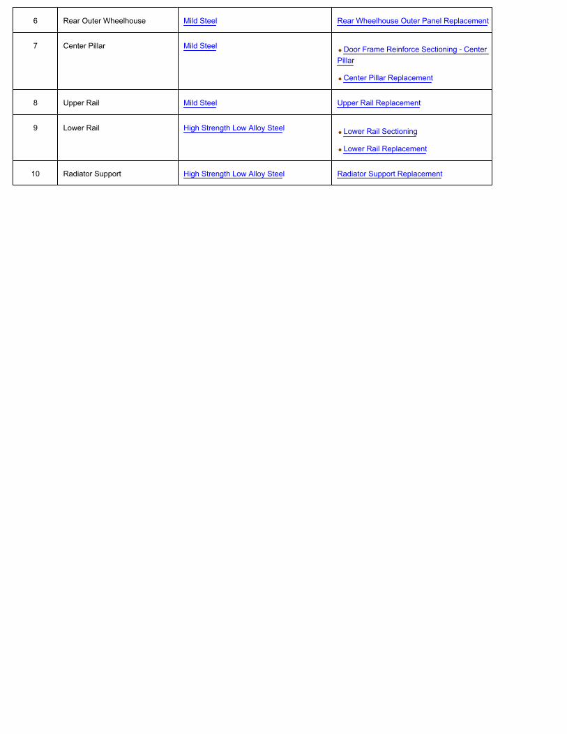
6 Rear Outer Wheelhouse Mild Steel Rear Wheelhouse Outer Panel Replacement
7 Center Pillar Mild Steel • Door Frame Reinforce Sectioning - CenterPillar
• Center Pillar Replacement
8 Upper Rail Mild Steel Upper Rail Replacement
9 Lower Rail High Strength Low Alloy Steel • Lower Rail Sectioning
• Lower Rail Replacement
10 Radiator Support High Strength Low Alloy Steel Radiator Support Replacement

RepairInstructionsFront Wheelhouse Panel Replacement
Removal Procedure
Warning: Refer to Approved Equipment for Collision Repair Warning.
Warning: Refer to Foam Sound Deadeners Warning.
Note:
• Model year 2004 and prior vehicles are not manufactured with laminated steel in front of the dashes. Therefore, the front wheelhouse assembly can be metalinert gas (MIG) welded instead of the rivet and bonding process, as stated in these instructions.
The front of the dash panel is formed from laminated steel. This steel is constructed by bonding 2 pieces of cold rolled steel (1) with a viscoelasticlayer of adhesive (2). MIG welding laminated steel does not meet GM Corporate standards for structural integrity. As an alternative, all factory weldswill be replaced by using the rivet and adhesive bond method described in the installation portion of this procedure. The rivet and adhesive bondmethod must only be used in the areas, as described in this procedure.
• Failure to follow this procedure will compromise the structural integrity of the vehicle.
1. Disable the SIR system. Refer to SIR Disabling and Enabling.
2. Disconnect the negative battery cable. Refer to Battery Negative Cable Disconnection and Connection.
Warning: Refer to Collision Sectioning Warning.
3. Remove all related panels and components.
4. Repair as much of the damage as possible.
5. Remove the sealers and the anti-corrosion materials from the repair area, as necessary. Refer to Anti-Corrosion Treatment and Repair.

Note: Note the number and location of the factory welds for installation of the full wheelhouse service part.
6. Remove the radiator support assembly. Refer to Radiator Support Replacement.
7. Remove the upper fender rail. Refer to Upper Rail Replacement.
Note: Drill through the wheelhouse flange only. Do NOT drill into the dash panel or the inner reinforcements.
8. Using an 8-mm (5/16-in) spot weld remover, locate and drill out the factory welds on the weld flange connecting the wheelhouse to the dash panel.
9. Remove the wheelhouse.
Installation Procedure

1. Position the service wheelhouse to the vehicle using 3-dimensional measuring equipment.
2. Clamp the wheelhouse in place.
3. Using a 7-mm (17/64-in) bit, drill the rivet attachment holes through the service wheelhouse and the dash panel, in the exact locations as noted from thefactory wheelhouse.
4. Remove the service wheelhouse.

Note: If the location of the original plug weld holes cannot be determined, space the plug weld holes every 40 mm (1.5 in) apart.
5. Drill 8-mm (5/16-in) plug weld holes in the service wheelhouse, as necessary, in the remaining locations noted from the original wheelhouse.
6. Prepare the plug weld mating surfaces, as necessary.
7. Apply 3M® Weld-Thru Coating P/N 05913 or equivalent to the plug weld mating surfaces.
8. Prepare the bond mating areas by grinding the body mating and the service part flanges to bare steel. Do NOT damage the corners or thin the metalduring the grinding process.
9. Clean the mating surfaces.

Note: The adhesive has a 40–50 minute working time. Do NOT allow the adhesive to cure prior to installing the service wheelhouse.
10. Apply a 3–6 mm (1/8 to 1/4 in) bead of metal panel bonding adhesive GM P/N 12378567 (Canadian P/N 88901675) or equivalent to both of the matingsurfaces.
11. Using a small acid brush, spread a coat of adhesive to both of the mating surfaces. Cover all of the bare metal to ensure corrosion protection.
12. Apply a 3–6 mm (1/8 to 1/4 in) bead of metal panel bonding adhesive GM P/N 12378567 (Canadian P/N 88901675) or equivalent to the mating surface ofthe service wheelhouse.

Note: Do NOT pull the wheelhouse off of the dash after adhesion. To align the parts, slide the wheelhouse against the front of the dash.
13. Position the service wheelhouse to the vehicle using 3-dimensional measuring equipment.
14. Clamp the wheelhouse in place.
Note: Verify proper positioning of the service wheelhouse prior to riveting and welding.
15. Install the 9 mm (11/32 in) long rivets so that the rivet head contacts the passenger compartment side of the dash.
16. Remove the excess adhesive from the wheelhouse area.
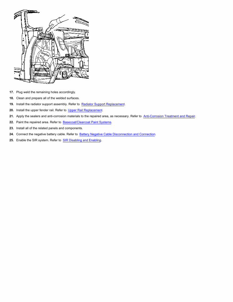
17. Plug weld the remaining holes accordingly.
18. Clean and prepare all of the welded surfaces.
19. Install the radiator support assembly. Refer to Radiator Support Replacement.
20. Install the upper fender rail. Refer to Upper Rail Replacement.
21. Apply the sealers and anti-corrosion materials to the repaired area, as necessary. Refer to Anti-Corrosion Treatment and Repair.
22. Paint the repaired area. Refer to Basecoat/Clearcoat Paint Systems.
23. Install all of the related panels and components.
24. Connect the negative battery cable. Refer to Battery Negative Cable Disconnection and Connection.
25. Enable the SIR system. Refer to SIR Disabling and Enabling.

Front Wheelhouse Extension Replacement
Removal Procedure
Warning: Refer to Approved Equipment for Collision Repair Warning.
1. Disable the SIR system. Refer to SIR Disabling and Enabling.
2. Disconnect the negative battery cable. Refer to Battery Negative Cable Disconnection and Connection.
3. Remove all related panels and components.
4. Repair as much of the damage as possible to factory specifications. Refer to Dimensions - Body.
Warning: Refer to Foam Sound Deadeners Warning.
5. Note the location and remove the sealers and anti-corrosion materials from the repair area, as necessary. Refer to Anti-Corrosion Treatment and Repair.
6. Remove the radiator support. Refer to Radiator Support Replacement.
Note: Do not damage any inner panels or reinforcements.
7. Locate and drill out all factory welds. Note the number and location of welds for installation of the service part.

8. Remove the damaged apron extension.
Installation Procedure
Note: If the location of the original plug weld holes can not be determined, or if structural weld-thru adhesive is present, space the plug weld holes every40 mm (1½ in) apart.
1. Drill 8 mm (5/16 in) plug weld holes in the service part as necessary in the locations noted from the original panel and along the sectioning cut.
2. Prepare all mating surfaces as necessary.
3. Apply 3M® Weld-Thru coating P/N 05916 or equivalent to all mating surfaces

4. Position the apron extension.
5. Plug weld accordingly.
6. Replace the radiator support. Refer to Radiator Support Replacement.
7. Clean and prepare all welded surfaces.
8. Apply the sealers and anti-corrosion materials to the repair area, as necessary. Refer to Anti-Corrosion Treatment and Repair.
9. Paint and repair the area. Refer to Basecoat/Clearcoat Paint Systems.
10. Install all related panels and components.
11. Connect the negative battery cable. Refer to Battery Negative Cable Disconnection and Connection.
12. Enable the SIR system. Refer to SIR Disabling and Enabling.
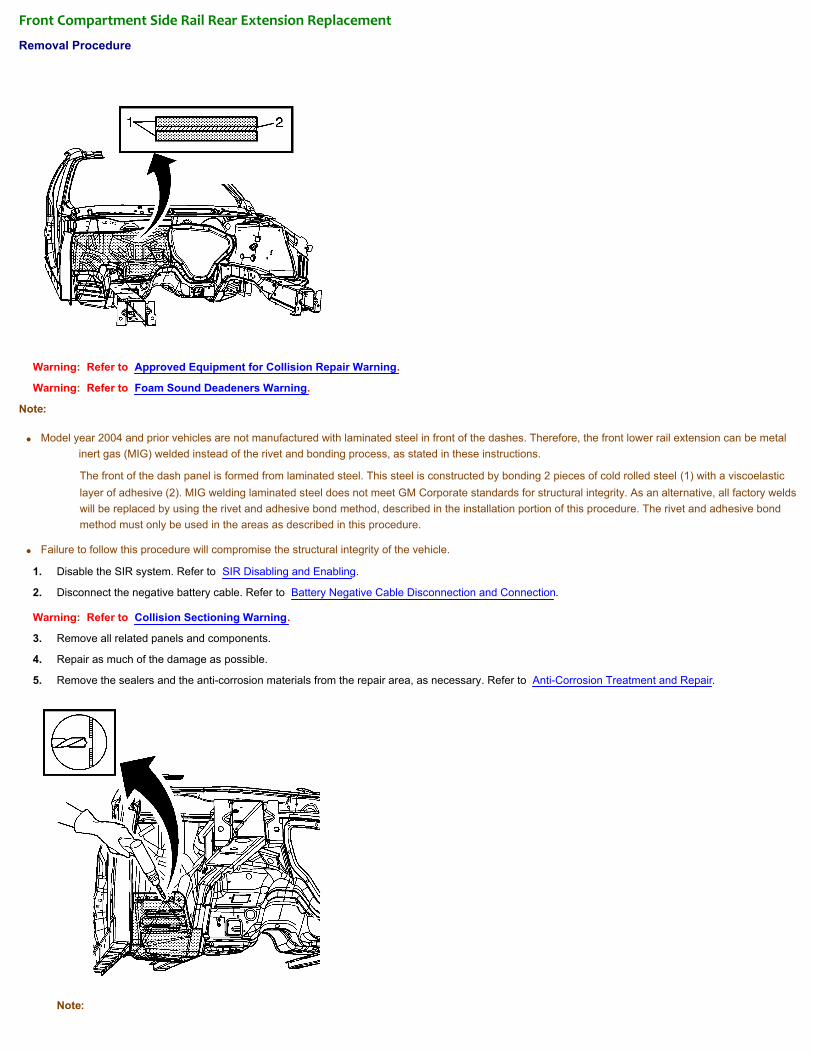
Front Compartment Side Rail Rear Extension Replacement
Removal Procedure
Warning: Refer to Approved Equipment for Collision Repair Warning.
Warning: Refer to Foam Sound Deadeners Warning.
Note:
• Model year 2004 and prior vehicles are not manufactured with laminated steel in front of the dashes. Therefore, the front lower rail extension can be metalinert gas (MIG) welded instead of the rivet and bonding process, as stated in these instructions.
The front of the dash panel is formed from laminated steel. This steel is constructed by bonding 2 pieces of cold rolled steel (1) with a viscoelasticlayer of adhesive (2). MIG welding laminated steel does not meet GM Corporate standards for structural integrity. As an alternative, all factory weldswill be replaced by using the rivet and adhesive bond method, described in the installation portion of this procedure. The rivet and adhesive bondmethod must only be used in the areas as described in this procedure.
• Failure to follow this procedure will compromise the structural integrity of the vehicle.
1. Disable the SIR system. Refer to SIR Disabling and Enabling.
2. Disconnect the negative battery cable. Refer to Battery Negative Cable Disconnection and Connection.
Warning: Refer to Collision Sectioning Warning.
3. Remove all related panels and components.
4. Repair as much of the damage as possible.
5. Remove the sealers and the anti-corrosion materials from the repair area, as necessary. Refer to Anti-Corrosion Treatment and Repair.
Note:

• Note the number and location of the factory welds, for installation of the rail side extension service part.
• Drill through the rail side extension flange only. Do NOT drill into the dash panel or the inner reinforcements.
6. Using an 8-mm (5/16-in) spot weld remover, locate and drill out the factory welds on the weld flange connecting the lower rail side extension to the vehiclestructure.
7. Remove the rail side extension.
Installation Procedure
1. Position the service rail side extension to the vehicle.
2. Clamp the rail in place.

3. Using a 7-mm (17/64-in) bit, drill the rivet attachment holes through the service rail side extension and the dash panel, in the exact locations, as notedfrom the factory rail side extension.
4. Remove the service rail side extension.
Note: If the location of the original plug weld holes cannot be determined, space the plug weld holes every 40 mm (1.5 in) apart.
5. Drill 8-mm (5/16-in) plug weld holes in the service rail side extension as necessary, in the remaining locations noted from the original rail side extension.
6. Prepare the plug weld mating surfaces, as necessary.
7. Apply 3M® Weld-Thru Coating P/N 05913 or equivalent to the plug weld mating surfaces.

8. Prepare the bond mating areas by grinding the body mating and the service part flanges to bare steel. Do NOT damage the corners or thin the metalduring the grinding process.
9. Clean the mating surfaces.
Note: The adhesive has a 40–50 minute working time. Do NOT allow the adhesive to cure prior to installing the service rail side extension.
10. Apply a 3–6 mm (1/8 to 1/4 in) bead of metal panel bonding adhesive GM P/N 12378567 (Canadian P/N 88901675) or equivalent to both of the matingsurfaces.

11. Using a small acid brush, spread a coat of adhesive to both of the mating surfaces. Cover all of the bare metal to ensure corrosion protection.
12. Apply a 3–6 mm (1/8 to 1/4 in) bead of metal panel bonding adhesive GM P/N 12378567 (Canadian P/N 88901675) or equivalent to the mating surface ofthe service rail side extension.
Note: Do NOT pull the service rail side extension off of the dash after adhesion. To align the parts, slide the service rail side extension against the frontof the dash.
13. Position the service rail side extension to the vehicle using 3-dimensional measuring equipment.
14. Clamp the service rail side extension in place.

Note: Verify proper positioning of the service rail side extension prior to riveting and welding.
15. Install the 9-mm (11/32-in) long rivets so that the rivet head contacts the passenger compartment side of the dash.
16. Install the 14-mm (17/32-in) long rivets so that the rivet head contacts the passenger compartment side of the dash.
17. Remove the excess adhesive from the service rail side extension area.
18. Plug weld the remaining holes accordingly.
19. Clean and prepare all of the welded surfaces.

20. Apply the sealers and anti-corrosion materials to the repaired area, as necessary. Refer to Anti-Corrosion Treatment and Repair.
21. Paint the repaired area. Refer to Basecoat/Clearcoat Paint Systems.
22. Install all of the related panels and components.
23. Connect the negative battery cable. Refer to Battery Negative Cable Disconnection and Connection.
24. Enable the SIR system. Refer to SIR Disabling and Enabling.

Rear Wheelhouse Outer Panel Replacement
Removal Procedure
Warning: Refer to Approved Equipment for Collision Repair Warning.
Note: Although full replacement of the rear outer wheelhouse can be performed, sectioning procedures have been developed for use when damage permits.
1. Remove all of the related panels and components including the quarter panel.
2. Visually inspect and restore as much of the damage as possible.
3. Remove the following materials as necessary:
• The sealers
• The sound deadeners
• The anti-corrosion materials
4. After removing the quarter panel, locate, mark and drill out the welds attaching the reinforcement panel (1) to the outer wheelhouse and the quarter panel.
5. Apply a strip of 25 mm (1 in) masking tape along the horizontal surface of the bend in the wheelhouse (2).
6. Cut along the outboard side of the masking tape to create a 25 mm (1 in) flange (2).
7. Remove the damaged section of the wheelhouse (3).
Installation Procedure
1. Cut the wheelhouse service part (1) along the corner of the bend (2).
2. Remove and discard the unused section of the wheelhouse.
3. On the service part, drill 8 mm (5/16 in) plug weld holes every 40 mm (1½ in) along the cut.

4. Prepare the mating surfaces as necessary. Inspect for proper fit of the service part.
5. Apply 3M Weld-Thru Coating P/N 05916 or equivalent to all mating surfaces.
6. Check for proper fit and plug weld accordingly (2). Take care not to warp or distort the metal.
7. Repair or replace the outer wheelhouse reinforcement as necessary.
8. Position the reinforcement panel as noted from the original panel location.
9. Plug weld accordingly.
10. Clean and prepare welded surfaces.
Note: Prior to refinishing, refer to GM 4901MD-99 Refinish Manual for recommended products. Do not combine paint systems. Refer to paintmanufacturer's recommendations.
11. Prime with 2-part catalyzed primer.
12. Apply the sealers and the anti-corrosion materials as necessary.
13. Install all of the related panels and components.

Radiator Support Replacement
Removal Procedure
Warning: Refer to Approved Equipment for Collision Repair Warning.
1. Remove all related panels and components.
2. Visually inspect and restore as much of the damage as possible to factory specifications.
3. Locate, mark, and drill out all factory welds. Note the number and location of welds for installation of the service assembly.
4. Remove the damaged radiator support assembly.
Installation Procedure
1. Prepare the mating surfaces as necessary. Inspect for proper fit of the service part.
2. Check for proper fit of the service assembly.
3. Drill 8 mm (5/16 in) plug weld holes as necessary in the locations noted from the original assembly.
4. Apply 3M Weld-Thru Coating P/N 05916 or equivalent to all mating surfaces.
5. Position the service assembly using 3-dimensional measuring equipment.
6. Plug weld accordingly with frequent measurements to ensure proper fit and alignment.
7. Clean and prepare all welded surfaces.
8. Prime with 2-part catalyzed primer.
9. Apply sealers and anti-corrosion materials as necessary.
Note: Prior to refinishing, refer to GM 4901MD-99 Refinish Manual for recommended products. Do not combine paint systems. Refer to paint

manufacturer's recommendations.
10. Install all related panels and components.
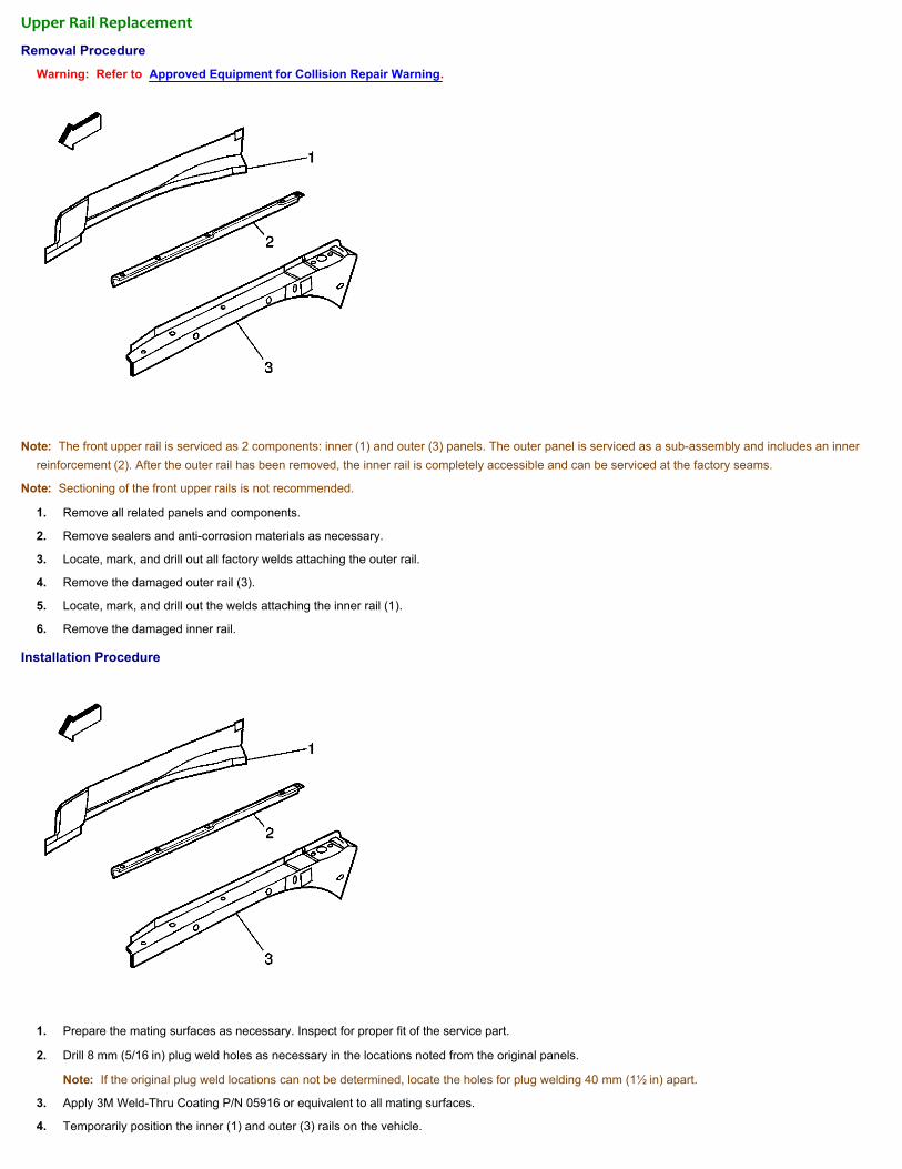
Upper Rail Replacement
Removal Procedure
Warning: Refer to Approved Equipment for Collision Repair Warning.
Note: The front upper rail is serviced as 2 components: inner (1) and outer (3) panels. The outer panel is serviced as a sub-assembly and includes an innerreinforcement (2). After the outer rail has been removed, the inner rail is completely accessible and can be serviced at the factory seams.
Note: Sectioning of the front upper rails is not recommended.
1. Remove all related panels and components.
2. Remove sealers and anti-corrosion materials as necessary.
3. Locate, mark, and drill out all factory welds attaching the outer rail.
4. Remove the damaged outer rail (3).
5. Locate, mark, and drill out the welds attaching the inner rail (1).
6. Remove the damaged inner rail.
Installation Procedure
1. Prepare the mating surfaces as necessary. Inspect for proper fit of the service part.
2. Drill 8 mm (5/16 in) plug weld holes as necessary in the locations noted from the original panels.
Note: If the original plug weld locations can not be determined, locate the holes for plug welding 40 mm (1½ in) apart.
3. Apply 3M Weld-Thru Coating P/N 05916 or equivalent to all mating surfaces.
4. Temporarily position the inner (1) and outer (3) rails on the vehicle.

5. Use 3-dimensional measuring to locate and mark front fender mounting-bolt holes in the outer rail (2).
6. Drill 5.5 mm (7/32 in) holes for self-tapping bolts as marked.
7. When the service panels are correctly positioned, remove the outer panel and plug weld the inner panel as necessary.
8. Reposition the outer rail with frequent measurements to ensure proper fit and alignment.
9. Plug weld accordingly.
10. Clean and prepare all of the welded surfaces.
Note: Prior to refinishing, refer to GM 4901MD-99 Refinish Manual for recommended products. Do not combine paint systems. Refer to paintmanufacturer's recommendations.
11. Prime with 2-part catalyzed primer.
12. Apply the sealers and the anti-corrosion materials as necessary.
13. Install all of the related panels and components.

Lower Rail Sectioning
Removal Procedure
Warning: Refer to Approved Equipment for Collision Repair Warning.
Caution: Sectioning should take place only in the locations recommended in the service instructions. Failure to follow these instructions may compromise thestructural integrity of the vehicle.
Note: Sectioning procedures have been developed to simplify repair of the lower rails, providing the majority of the damage can be returned to factoryspecifications. This allows the damaged front section to be replaced without performing a full rail replacement. The rails are manufactured with diemarks (1)inboard and outboard to indicate the location for the sectioning joint.
Note: If the damage exceeds the recommended area for sectioning and the rail cannot be straightened, the complete rail must be replaced.
1. Support the powertrain assembly.
2. Remove 4 engine cradle bolts.
3. Position the cradle away from the rail.
Note: It is not necessary to completely remove the powertrain or engine cradle for rail sectioning.
4. Remove all panels and components necessary for access, including the strut and axle assemblies.
5. Remove sealers and anti-corrosion materials as necessary.
6. Locate the diemarks in the rail.
7. Use a straight edge to scribe lines around the rail.

8. Mark and cut the damaged rail at the diemarks.
9. Remove the damaged section of the rail.
Installation Procedure
1. Measure from the diemarks to add 20 mm (3/4 in) in length to the service part.
2. Align marks with a straight edge and scribe line for sectioning cut.
3. Cut the service part along the marked lines.
4. Leave 20 mm (3/4 in) added lengths to the service part for sectioning overlap.
5. Cut and remove approximately 20 mm (3/4 in) of the outboard and downward turned flanges of the service part.

6. Cut 5 mm (3/16 in) wide and 20 mm (3/4 in) long slots along the corners of the service part to create tabs on the four sides of the rail.
7. Step the top, bottom and side tabs inward to allow the service part to fit inside the original rail.
8. Apply 3M Weld-Thru Coating P/N 05916 or equivalent to all mating surfaces.
9. Welds the tabs (1) together along the corners of the service part.
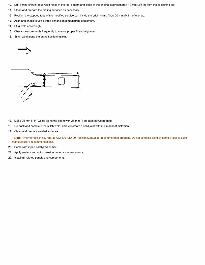
10. Drill 8 mm (5/16 in) plug weld holes in the top, bottom and sides of the original approximately 10 mm (3/8 in) from the sectioning cut.
11. Clean and prepare the mating surfaces as necessary.
12. Position the stepped tabs of the modified service part inside the original rail. Allow 20 mm (¾ in) of overlap.
13. Align and check fit using three dimensional measuring equipment.
14. Plug weld accordingly.
15. Check measurements frequently to ensure proper fit and alignment.
16. Stitch weld along the entire sectioning joint.
17. Make 25 mm (1 in) welds along the seam with 25 mm (1 in) gaps between them.
18. Go back and complete the stitch weld. This will create a solid joint with minimal heat distortion.
19. Clean and prepare welded surfaces.
Note: Prior to refinishing, refer to GM 4901MD-99 Refinish Manual for recommended products. Do not combine paint systems. Refer to paintmanufacturer's recommendations.
20. Prime with 2-part catalyzed primer.
21. Apply sealers and anti-corrosion materials as necessary.
22. Install all related panels and components.

Lower Rail Replacement
Removal Procedure
Warning: Refer to Approved Equipment for Collision Repair Warning.
Warning: Refer to Foam Sound Deadeners Warning.
Note:
• Model year 2004 and prior vehicles are not manufactured with laminated steel in front of the dashes. Therefore, the front lower rail can be metal inert gas(MIG) welded instead of the rivet and bonding process, as stated in these instructions.
• Failure to follow this procedure will compromise the structural integrity of the vehicle.
The front of the dash panel is formed from laminated steel. This steel is constructed by bonding 2 pieces of cold rolled steel (1) with a viscoelasticlayer of adhesive (2). MIG welding laminated steel does not meet GM Corporate standards for structural integrity. As an alternative, all factory weldswill be replaced by using the rivet and adhesive bond method described in the installation portion of this procedure. The rivet and adhesive bondmethod must only be used in the areas as described in this procedure.
1. Disable the SIR system. Refer to SIR Disabling and Enabling.
2. Disconnect the negative battery cable. Refer to Battery Negative Cable Disconnection and Connection.
Warning: Refer to Collision Sectioning Warning.
3. Remove all related panels and components.
4. Repair as much of the damage as possible.
5. Remove the sealers and the anti-corrosion materials from the repair area, as necessary. Refer to Anti-Corrosion Treatment and Repair.
Note: Note the number and location of the factory welds for installation of the full rail service part.
6. Remove the front wheelhouse assembly. Refer to Front Wheelhouse Panel Replacement.
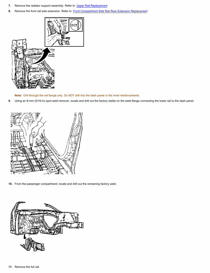
7. Remove the radiator support assembly. Refer to Upper Rail Replacement.
8. Remove the front rail side extension. Refer to Front Compartment Side Rail Rear Extension Replacement.
Note: Drill through the rail flange only. Do NOT drill into the dash panel or the inner reinforcements.
9. Using an 8-mm (5/16-in) spot weld remover, locate and drill out the factory welds on the weld flange connecting the lower rail to the dash panel.
10. From the passenger compartment, locate and drill out the remaining factory weld.
11. Remove the full rail.

Installation Procedure
Note: Failure to install the front compartment lower rail reinforcement to the front compartment lower rail will compromise the structural integrity of thevehicle.
1. Drill 8-mm (5/16-in) plug weld holes in the service front lower rail reinforcement in the location noted from the original rail.
2. Prepare the plug weld mating surfaces, as necessary.
3. Apply 3M® Weld-Thru Coating P/N 05913 or equivalent to the plug weld mating surfaces.
4. Position the front lower rail reinforcement.
5. Plug weld the holes accordingly.

6. Position the service rail to the vehicle using 3-dimensional measuring equipment.
7. Clamp the rail in place.
8. Using a 7-mm (17/64-in) bit, drill the rivet attachment holes through the service rail and the dash panel in the exact locations, as noted from the factoryrail.
Note: If the location of the original plug weld holes cannot be determined, space the plug weld holes every 40 mm (1.5 in) apart.
9. Remove the service rail.
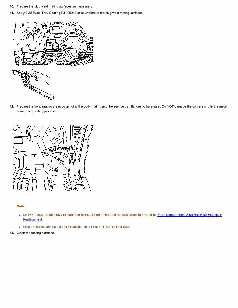
10. Prepare the plug weld mating surfaces, as necessary.
11. Apply 3M® Weld-Thru Coating P/N 05913 or equivalent to the plug weld mating surfaces.
12. Prepare the bond mating areas by grinding the body mating and the service part flanges to bare steel. Do NOT damage the corners or thin the metalduring the grinding process.
Note:
• Do NOT allow the adhesive to cure prior to installation of the front rail side extension. Refer to Front Compartment Side Rail Rear ExtensionReplacement.
• Note the necessary location for installation of a 14-mm (17/32-in) long rivet.
13. Clean the mating surfaces.

Note: The adhesive has a 40–50 minute working time. Do NOT allow the adhesive to cure prior to installing the service rail.
14. Apply a 3–6 mm (1/8 to 1/4 in) bead of metal panel bonding adhesive GM P/N 12378567 (Canadian P/N 88901675) or equivalent to both of the matingsurfaces.
15. Using a small acid brush, spread a coat of adhesive to both of the mating surfaces. Cover all of the bare metal to ensure corrosion protection.
16. Apply a 3–6 mm (1/8 to 1/4 in) bead of metal panel bonding adhesive GM P/N 12378567 (Canadian P/N 88901675) or equivalent to the mating surface ofthe service rail.

Note: Do NOT pull the rail off of the dash after adhesion. To align the parts, slide the rail against the front of the dash.
17. Position the service rail to the vehicle using 3-dimensional measuring equipment.
18. Clamp the rail in place.
Note: Verify proper positioning of the service rail prior to riveting and welding.
19. Install the 9-mm (11/32-in) long rivets, so that the rivet head contacts the passenger compartment side of the dash.

20. Install the 14-mm (17/32-in) long rivet, so that the rivet head contacts the passenger compartment side of the dash, extending through the front rail andthrough the rail side extension.
21. Remove the excess adhesive from the rail area.
22. Plug weld the remaining holes, accordingly.
23. Clean and prepare all of the welded surfaces.
24. Install the front wheelhouse assembly. Refer to Front Wheelhouse Panel Replacement.
25. Install the front rail side extension. Refer to Front Compartment Side Rail Rear Extension Replacement.
26. Install the radiator support assembly. Refer to Upper Rail Replacement.
27. Apply the sealers and anti-corrosion materials to the repaired area, as necessary. Refer to Anti-Corrosion Treatment and Repair.
28. Paint the repaired area. Refer to Basecoat/Clearcoat Paint Systems.
29. Install all of the related panels and components.
30. Connect the negative battery cable. Refer to Battery Negative Cable Disconnection and Connection.
31. Enable the SIR system. Refer to SIR Disabling and Enabling.

Front Hinge Pillar Sectioning
Removal Procedure
Warning: Refer to Approved Equipment for Collision Repair Warning.
Note: Do not cut adjacent panels.
Note: Follow general sectioning for the outer rocker panel. Sectioning should take place in shaded areas only. There are key structural areas on the outerrocker panel where sectioning should not be performed. Sectioning in these areas may compromise the structural integrity of the vehicle.
1. Visually inspect and restore as much of the damage as possible to factory specifications.
2. Remove all related panels and components.
3. Position all wiring out of the way to prevent damage and for best access to vehicle.
4. Remove all sealers and anti-corrosion materials as necessary.
5. On the original outer door frame (1) measure down 35 mm (1 3/8 in) from the large wiring harness hole in the pillar and mark a horizontal line (4).
6. Cut the outer door frame along this line for sectioning.
7. Perform additional sectioning procedures as necessary to remove damaged areas of the door frame opening.
8. Locate and mark all factory welds. Note the number and location of welds for installation of the service part.
9. Drill out all factory welds as necessary.
Note: Note the location of the sound deadening foam for installation.
10. Remove the damaged section of the outer door frame opening (2).
Installation Procedure
1. On the service part (2), mark a horizontal line to leave a gap of 1 ½ times the thickness of the metal at the section joint.
2. Cut the service panel along this line.

3. Drill 8 mm (5/16 mm) holes for plug welding in the service part in the locations noted from the original panel.
4. Drill holes for plug welding along the sectioning cut on the service part. Locate these holes approximately 13 mm (½ in) from the edge of the sectioningcut.
5. Apply 3M Weld-Thru Coating P/N 05916 or equivalent to all mating surfaces.
6. Use the inner reinforcement (3) as a backing plate.
7. Stitch weld along the entire joint with 25 mm (1 in) welds along the seams with 25 mm (1 in) gaps between.
8. Go back and complete the stitch weld. This will create a solid joint with minimal heat distortion.
9. Complete all other welds and sectioning procedures as necessary.
10. Clean and prepare welded surfaces.
Note: Prior to refinishing, refer to GM 4901MD-99 Refinish Manual for recommended products. Do not combine paint systems. Refer to paintmanufacturer's recommendations.
11. Prime with two-part catalyzed primer.
Note: It is necessary to apply the sound-deadening foam in the locations as noted from removal.
12. Apply sealers and anti-corrosion materials as necessary.
13. Install all related panels and components.

Front Inner Hinge Pillar Reinforcement Sectioning
Removal Procedure
Warning: Refer to Approved Equipment for Collision Repair Warning.
Note: Sectioning of the inner reinforcement panel (3) can only take place with outer door frame replacement or sectioning procedures. Sectioning theouter door (1) frame at the front hinge pillar requires a 25 mm (1 in) offset from the inner reinforcement sectioning joint. The inner reinforcement can serveas a backing plate for the outer panel sectioning.
1. Visually inspect and restore as much of the damage as possible to factory specifications.
2. Remove all related panels and components.
3. Position all wiring out of the way to prevent damage and for best access to vehicle.
4. Remove all sealers and anti-corrosion materials as necessary.
5. On the original reinforcement panels (1) measure down 90 mm (3 9/16 in) from the large wiring harness hole in the pillar and mark a horizontal line.
6. Cut the inner reinforcement along this line for sectioning.
7. Locate and mark all factory welds. Note the number and location of welds for installation of the service part.
8. Drill out all factory welds as necessary.
Note: Note the locations of the sound-deadening foam for installation.
9. Remove the damaged section of the inner reinforcement (2).
Installation Procedure

1. Cut and remove 30 mm (1 3/16 in) from the flanges on either side of the remaining section of the original hinge pillar to create a 30 mm (1 3/16 in) flange.
2. Cut 5 mm (3/16 in) wide gaps in the bottom corners.
3. Step the tabs inward to allow the door frame inner reinforcement service section to fit over the original inner reinforcement.
4. Apply 3M Weld-Thru Coating P/N 05916 or equivalent to all mating surfaces.
5. Weld the tabs together along the edges (1).

6. On the service part (1) measure 60 mm (2 3/8 in) down from the large wiring harness hole in the hinge pillar and mark a horizontal line.
7. Cut the hinge pillar along this line.
8. Drill 8 mm (5/16 in) plug weld holes as necessary in the locations noted from the original panel.
9. Drill plug weld holes along the sectioning cut of the service part (2).
10. Prepare the mating surfaces as necessary. Position the service section (2) over the stepped tab on the original inner reinforcement (1).
11. Check and make sure the door hinge bolt holes are properly located.

12. Plug weld accordingly.
13. Stitch weld along the entire joint (1).
14. Make 25 mm (1 in) welds along the seam with 25 mm (1 in) gaps between.
15. Go back and complete the stitch weld. This will create a solid joint with minimal heat distortion.
16. Clean and prepare welded surfaces.
Note: Prior to refinishing, refer to GM 4901MD-99 Refinish Manual for recommended products. Do not combine paint systems. Refer to paintmanufacturer's recommendations.
17. Prime with 2-part catalyzed primer.
Note: It is important to re-apply the sound-deadening foam in the locations noted from the removal process.
18. Apply sealers and anti-corrosion materials as necessary.
19. Install all related panels and components.

Door Frame Reinforce Sectioning - Center Pillar
Removal Procedure
Warning: Refer to Approved Equipment for Collision Repair Warning.
Note: The striker plate is mounted in a cage that allows some degree of adjustment independent of the outer panels position. Use body dimensions toensure that the striker mounting location falls within the plates range of adjustment.
1. Remove all related panels and components.
2. Visually inspect and restore as much of the damage as possible.
3. Remove sealers and anti-corrosion materials as necessary.
Note: When sectioning both the inner (3) and the outer panels (2) this should result in a 100 mm (4 in) offset in the sectioning joints. Use care not to cutthe inner door opening frame when cutting the center pillar reinforcement.
Note: Sectioning of the center pillar reinforcement should be performed only in the specified sectioning locations.
4. Cut the reinforcement (3) panel 250 mm (13 3/4 in) from the lower edge of the door opening (1).
5. Locate and mark all factory welds. Note the number and location of welds for installation of the service assembly.
6. Drill out all factory welds.
Installation Procedure
1. On the service part (5) mark a horizontal line to leave a gap of 1 ½ times the thickness of the metal (6) at the sectioning joint.
2. Cut the service reinforcement panel along this line.
3. Cut a 50 mm (2 in) piece from the unused portion of the service part (5) for a backing plate.
4. Remove the flange on each side of the backing plate (4) so that it will fit behind the sectioning joint (6).

5. Drill 8 mm (5/16 in) holes for plug welding in the service part in the location noted from the original panel.
6. Drill holes for plug welding along the sectioning cuts on both the service part (5) and the original panel (3).
7. Locate these holes approximately 13 mm (1/2 in) from the edge of the sectioning cuts.
8. Prepare the mating surfaces as necessary. Position the backing plate with 25 mm (1 in) of the backing plate exposed. Position the service part (5) tooverlap the exposed backing plate.
9. Apply 3M Weld-Thru Coating P/N 05916 or equivalent to all mating surfaces.
10. Make 25 mm (1 in) welds along the seams with 25 mm (1 in) gaps between.
11. Go back and complete the stitch weld. This will create solid joint with minimal heat distortion.
12. Complete all other welds as necessary.
13. Clean and prepare welded surfaces.
Note: Prior to refinishing, refer to GM 4901MD-99 Refinish Manual for recommended products. Do not combine paint systems. Refer to paintmanufacturer's recommendations.
14. Prime with 2 part catalyzed primer.
15. Apply sealers and anti-corrosion materials as necessary.

Center Pillar Replacement
Removal Procedure
Warning: Refer to Approved Equipment for Collision Repair Warning.
1. Visually inspect and restore as much of the damage as possible to factory specifications.
2. Remove all related panels and components.
3. Position all wiring out of the way to prevent damage.
4. Remove sealers and anti-corrosion materials as necessary.
5. On the original outer door frame (2) measure down from the lower edge (1) of the door opening 200 mm (8 in) and mark a horizontal line.
6. Cut the outer door frame along this line for sectioning. Do not cut into the inner reinforcement.
7. Locate and mark all factory welds. Note the number and location of welds for installation of the service section.
8. Drill out all factory welds as necessary.
9. Perform additional sectioning procedures as necessary to remove the center lock pillar.
10. Remove the damaged section of the door frame opening (4).
Installation Procedure
1. On the service part (4), mark a horizontal line to leave a gap of 1½ times the thickness of the metal (5) at the sectioning joint.
2. Cut the service panel along this line.
3. Drill 8 mm (5/16 in) holes for plug welding in the service part (4) in the locations noted from the original panel.
4. Drill holes for plug welding long the sectioning cuts on the services part.
5. Locate these holes approximately 13 mm (17/32 in) from the edge of the sectioning cuts.

6. Prepare the mating surfaces as necessary. Position the service part using three-dimensional measuring equipment.
7. Apply 3M Weld-Thru Coating P/N 05916 or equivalent to all mating surfaces.
8. Plug weld accordingly.
9. Use the inner reinforcement (3) as a backing plate and stitch weld along the entire sectioning joint.
10. Make 25 mm (1 in) welds along the seam with 25 mm (1 in) gaps between.
11. Go back and complete the stitch weld. This will create a solid joint with minimal heat distortion.
12. Complete all other welds and sectioning procedures as necessary.
13. Clean and prepare welded surfaces.
Note: Prior to refinishing, refer to GM 4901MD-99 Refinish Manual for recommended products. Do not combine paint systems. Refer to paintmanufacturer's recommendations.
14. Prime with 2-part catalyzed primer.
15. Apply sealers and anti-corrosion materials as necessary.
16. Install all related panels and components.

General Door Frame Opening Sectioning
Removal Procedure
Warning: Refer to Approved Equipment for Collision Repair Warning.
1. Visually inspect and restore as much of the damage as possible.
2. Remove all related panels and components.
3. Remove sealers and anti-corrosion materials as necessary.
4. Cut the panel in the areas where the sectioning is to take place. Sectioning should take place in shaded areas only.
Note: Use care not to cut the inner reinforcements when cutting the outer door opening frame.
5. Locate and mark all factory welds. Note the number and location of welds for installation of the service assembly.
6. Drill out all factory welds.
Note: Note the location of the sound deadening foam for installation.
7. Remove the damaged outer door opening frame.
Installation Procedure
Note: Sectioning in the rocker locations requires the use of a 100 mm (4 in) backing plate.

1. On the service part, mark a line to leave a gap of one and one-half times the thickness of the metal at the sectioning joint (2).
2. Cut the outer door frame opening service part along this line.
3. Cut a 100 mm (4 in) piece (1) from the unused portion of the service part for a backing plate when sectioning in the rocker areas of the door frameopening.
4. Sectioning in the A, B, or C pillars of the outer door frame opening requires the use of a 50 mm (2 in) backing plate.
5. Cut a 50 mm (2 in) piece (1) from the unused portion of the service part for a backing plate, leaving a gap of 1½ times the thickness of the metal (2).

Note: When sectioning the outer door frame at the lower front hinge pillar of at the center lock pillar, the inner reinforcement panel can be used as abacking plate.
6. Drill 8 mm (5/16 in) holes for plug welding in the service part in the locations noted from the original panel.
7. Drill holes for plug welding along the sectioning cuts on both the service part and the original panel.
8. Prepare the mating surfaces as necessary. Position the backing plates on the body with 50 percent of the backing plate exposed.
9. Apply 3M Weld-Thru Coating P/N 05916 or equivalent to all mating surfaces.
10. Plug weld accordingly.
11. Position the service part to overlap the exposed 50 percent of the backing plate.
12. Check the fit using 3-dimensional measuring equipment.
13. Plug weld accordingly.
14. Stitch weld along the entire sectioning joint.
15. Make 25 mm (1 in) welds along the seam with 25 mm (1 in) gaps between.
16. Go back and complete the stitch weld. This will create a solid joint with minimal heat distortion.
17. Complete all other welds and sectioning procedures as necessary.
18. Clean and prepare welded surfaces.
Note: Prior to refinishing, refer to GM 4901MD-99 Refinish Manual for recommended products. Do not combine paint systems. Refer to paintmanufacturer's recommendations.
Note: Apply the sound deadening foam in the locations noted from the removal process.
19. Prime with 2-part catalyzed primer.
20. Apply sealers and anti-corrosion materials as necessary.
21. Install all related panels and components.
Roof Panel Replacement
Removal Procedure
Warning: Refer to Approved Equipment for Collision Repair Warning.
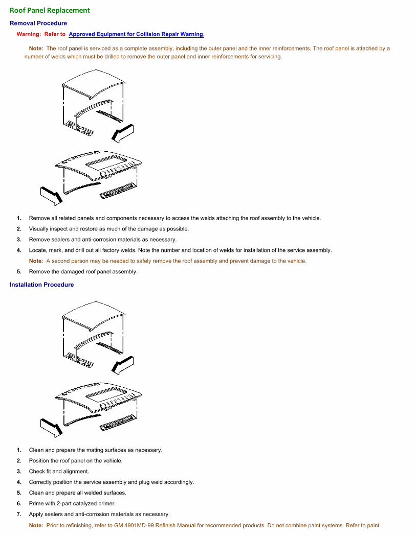
Note: The roof panel is serviced as a complete assembly, including the outer panel and the inner reinforcements. The roof panel is attached by anumber of welds which must be drilled to remove the outer panel and inner reinforcements for servicing.
1. Remove all related panels and components necessary to access the welds attaching the roof assembly to the vehicle.
2. Visually inspect and restore as much of the damage as possible.
3. Remove sealers and anti-corrosion materials as necessary.
4. Locate, mark, and drill out all factory welds. Note the number and location of welds for installation of the service assembly.
Note: A second person may be needed to safely remove the roof assembly and prevent damage to the vehicle.
5. Remove the damaged roof panel assembly.
Installation Procedure
1. Clean and prepare the mating surfaces as necessary.
2. Position the roof panel on the vehicle.
3. Check fit and alignment.
4. Correctly position the service assembly and plug weld accordingly.
5. Clean and prepare all welded surfaces.
6. Prime with 2-part catalyzed primer.
7. Apply sealers and anti-corrosion materials as necessary.
Note: Prior to refinishing, refer to GM 4901MD-99 Refinish Manual for recommended products. Do not combine paint systems. Refer to paint

manufacturer's recommendations.
8. Install all related panels and components.

Quarter Panel Replacement
Removal Procedure
Warning: Refer to Approved Equipment for Collision Repair Warning.
Note: The quarter panel is serviced as a body side service assembly which includes the outer door frame opening, and the lower rear quarter close-out panel.Replacement of the quarter panel requires removal of the quarter glass and the back glass. A special sectioning procedure has been developed for improvedserviceability.
1. Visually inspect and restore as much of the damage as possible to factory specifications.
2. Remove all related panels and components.
3. Remove sealers and anti-corrosion materials as necessary.
4. Scribe a cut line in upper quarter area.
5. Scribe a cut line in the rocker panel area.
6. Cut damaged section at marked locations.
7. Locate and mark all factory welds. Note the number and location of welds for installation of the service assembly.
8. Drill out all factory welds.
Note: Note the location of the sound deadening foam for installation.
9. Remove the damaged quarter panel.
Installation Procedure
1. Prepare the mating surfaces as necessary.
2. On the service part, locate where to cut the upper quarter and rocker areas. Leave extra length in these areas for trimming.
3. Refer to general sectioning for appropriate usage of backing plates.
4. Trim the quarter panel to leave a gap of one and one-half times the thickness of the metal at the sectioning joints.
5. Check for proper fit and alignment.
6. Plug weld accordingly.
Note: The glass bonding area should be a primer surface ONLY, and NOT an after-market top-coated (paint, or color coated) surface.
7. Clean and prepare all welded surfaces.
Note: Prior to refinishing, refer to GM 4901MD-99 Refinish Manual for recommended products. Do not combine paint systems. Refer to paintmanufacturer's recommendation.
8. Prime with 2-part catalyzed primer.
Note: It is important to apply the sound deadening foam in the locations noted from removal.
9. Apply sealers and anti-corrosion materials as necessary.
10. Install all related panels and components.

Rear Rail Replacement
Removal Procedure
Warning: Refer to Approved Equipment for Collision Repair Warning.
Note: Full rail replacement will require the removal of either the crossbar or an inner wheelhouse assembly. If sectioning is permitted, locate the diemark (3) onthe lower surface of rail.
1. Remove all related panels and components including the rear suspension and seat.
2. Visually inspect and restore as much of the damage as possible to factory specifications.
3. Remove the following as necessary:
• Sealers
• Sound deadeners
• Anti-corrosion materials
4. Locate, mark, and drill out all factory welds attaching the control arm mounting bracket (1) and the rear rail (4) to the vehicle.
5. The factory welds attaching the control arm mounting bracket weld flange (6) to the inner rocker panel must be drilled out from inside the vehicle.
Note: The corner of the floor panel above this area will need to be positioned out of the way (6).
6. Locate, mark and drill out all factory welds. Note the number and location of welds for installation of the service assembly.
7. Remove the damaged rear rail assembly.
Installation Procedure
1. Clean and prepare the mating surfaces.

2. Check for proper fit of the rear rail service assembly.
3. Drill 8 mm (5/16 in) plug weld holes on the service assembly as necessary in the locations noted from the original assembly.
4. Position the service assembly.
5. Check fit with 3-dimensional measuring equipment.
6. Apply 3M Weld-Thru Coating P/N 05916 or equivalent to all mating surfaces.
7. Plug weld accordingly with frequent measurements to ensure proper fit.
8. Plug weld the control arm mounting bracket weld flange (6) to the inner rocker.
9. Reposition the floor panel into its original location.
10. Weld as necessary.
Note: The bumper mounting bracket (2) holes must be properly located and drilled. Use 3-dimensional measuring equipment.
11. Clean and prepare all welded surfaces.
Note: Prior to refinishing, refer to GM 4901MD-99 Refinish Manual for recommended products. Do not combine paint systems. Refer to paintmanufacturer's recommendations.
12. Prime with 2-part catalyzed primer.
13. Apply sealers and anti-corrosion materials as necessary.
14. Apply sound deadening materials to restore sound deadening quality as manufactured.
15. Install all related panels and components.

Rear Rail Sectioning
Removal Procedure
Warning: Refer to Approved Equipment for Collision Repair Warning.
Sectioning procedures can be used to repair the rear rail if just the portion rearward of the crossbar is damaged. Unique service parts are available forsectioning. The sub-assembly consists of the outer rail panel with the bumper mounting brackets attached.
Note: If damage exceeds the recommended area for sectioning and the rail cannot be straightened, the complete rail must be replaced.
1. Remove all related panels and components.
2. Visually inspect and restore as much of the damage as possible to factory specifications.
3. Remove sealers and anti-corrosion materials as necessary.
4. Locate, mark, and drill out all factory welds. Note the number and location of welds for installation of the service assembly.
5. Use a straight edge to scribe a line around the rail.
6. Cut the damaged rail (1).
7. Remove the damaged section of the rail.
Installation Procedure
Note: Note the size and the location of the precut service part.
1. Measure 30 mm (1 3/16 in) on the service part and mark cut lines.
2. Cut and remove 30 mm (1 3/16 in) from the flanges on either side (1) of the service rail (3) to create 30 mm (1 3/16 in) tabs.
3. Cut 5 mm (3/16 in) wide gaps in the bottom corners (2).

4. Step the tabs inward (1) to allow the service part (2) to fit inside of the original rail.
5. Apply 3M Weld-Thru Coating P/N 05916 or equivalent to all mating surfaces.
6. Weld the tabs together along the edges (1).
7. Clean and prepare the mating surfaces.
8. Position the service part.
9. Check fit with 3-dimensional measuring equipment.
10. Plug weld accordingly.
11. Stitch weld along the entire joint (2).
12. Make 25 mm (1 in) welds along the seam with 25 mm (1 in) gaps between.
13. Go back and complete the stitch weld. This will create a solid joint with minimal heat distortion.
Note: The bumper mounting holes must be properly located and drilled. Use 3–dimensional measuring equipment.
14. Clean and prepare welded surfaces.
Note: Prior to refinishing, refer to GM 4901MD-99 Refinish Manual for recommended products. Do not combine paint systems. Refer to paintmanufacturer's recommendations.
15. Prime with 2-part catalyzed primer.
16. Apply sealers and anti-corrosion materials as necessary.
17. Install all related panels and components.

Floor Panel Replacement
Removal Procedure
Warning: Refer to Approved Equipment for Collision Repair Warning.
Note: The damaged rear floor should be cut along the rearward edge of the rear crossbar (1), and the service part should be cut so that the new floorsection extends to the forward edge of the rear crossbar (2). This allows the two sections to overlap where the crossbar is attached (2). The cut to thedamaged floor will be about 790 mm (31 1/8 in) from the rear edge of the floor panel.
1. Remove all related panels and components as necessary, including the following:
• The rear end panel
• The quarter panels
• The quarter panel extensions
2. Visually inspect and restore as much of the damage as possible.
3. Remove the following as necessary:
• The sealers
• The sound deadeners
• The anti-corrosion materials
4. Locate and mark all factory welds rearward of the rear crossbar including those along the lower edge of the wheelhouse.
5. Note the number and location of welds for installation of the floor service assembly.
6. Drill out all factory welds.
Note: Drill out the factory welds rearward of the crossbar only. Do not drill out the welds attaching the floor to the crossbar.
7. Cut the damaged floor along the rear edge of the crossbar.
8. Do not damage the following:
• The rear rails
• The crossbar
• The wheelhouse
9. Remove the damaged floor section.
Installation Procedure

Note: The service part is supplied as a rear floor assembly.
1. Measure 960 mm (37 ¾ in) forward from the rear edge of the rear floor service assembly, mark the location, and cut accordingly.
2. Prepare the mating surfaces as necessary.
3. Check for proper fit.
4. Allow the floor service assembly (3) to overlap the original floor on top of the rear crossbar (2).
5. Mark the location of the rear rail and crossbar flanges on the bottom of the floor service assembly.
6. Drill 8 mm (5/16 in) plug weld holes as necessary in the locations noted from the original floor assembly (3).
7. Drill holes approximately 40 mm (1 in) apart where the new floor section attaches to the rear rail and crossbar flanges.
8. Position the service assembly and check for proper fit.
9. Apply 3M Weld-Thru Coating P/N 05916 or equivalent to all mating surfaces.
10. Plug weld accordingly (1).
11. Clean and prepare all welded surfaces.
Note: Prior to refinishing, refer to GM 4901MD-99 Refinish Manual for recommended products. Do not combine paint systems. Refer to paintmanufacturer's recommendations.
12. Apply 2-part catalyzed primer.
Note: The rear crossbar areas must be properly sealed from moisture and dirt to seal both the front and rear edges of the crossbar as well as the innerseams.
13. Apply the following materials as necessary:
• The sealers
• The sound deadeners
• The anti-corrosion materials
14. Install all related panels and components.

DescriptionandOperationDoor Frame Description
The outer door frame can be replaced as a complete service part or vairous segments can be sectioned. Complete service part replacement requires theremoval of the roof panel. Sectioning the outer door frame and inner door frame reinforcement is usually much faster and more cost effective. Since the outerdoor frame is manufactured as a single component, service parts for sectioning must be cut from the service panel and modified as necessary. Sectioningshould take place in shaded areas only.

High Strength Low Alloy Steel
This information provides repair recommendations and general guidelines for steel classified as High Strength Low Alloy Steel, also known as HSLA. This type ofsteel normally has a tensile strength range from 300–700 MPa.
General Motors recommends the following when repairing or replacing this type of steel during collision repair.
Recommended Repairs
• Cold repairs can be performed on this type of steel, unless the damage includes kinks. If the damage includes kinks, the part should be replaced.
• Controlled use of heat can be used to repair damage, if the heat does not exceed 650°C (1200°F). The heat should be applied a maximum of 2 times, forup to 90 seconds.
• Sectioning or partial replacement of this type of steel is recommended only at approved locations, in a specific sectioning procedure.
• When recommended in a specific sectioning procedure, this type of steel can be used as a weld plate for reinforcing the sectioning location.
• Squeeze Resistance Spot Welding can be used to replace factory spot welds, where applicable.
• MIG plug welding and MIG stitch welding can be used on this type of steel.
• MIG Brazing can be used on this type of steel.
Mild Steel
This information provides repair recommendations and general guidelines for steel classified as Mild Steel. This type of steel normally has a tensile strength lessthan 270 MPa. This includes the common steel names of:
• Mild Steel
• Bake Hardenable Steel (BH)
• Solid Solution Strengthened Steel
General Motors recommends the following when repairing or replacing this type of steel during collision repair.
Recommended Repairs:
• Cold repairs can be performed on this type of steel, unless the damage includes kinks. If the damage includes kinks, the part should be replaced.
• Controlled use of heat can be used to repair damage, if the heat does not exceed 650°C (1200°F). The heat should be applied a maximum of 2 times, forup to 90 seconds.
• Sectioning or partial replacement of this type of steel is recommended only at approved locations, in a specific sectioning procedure.
• When recommended in a specific sectioning procedure, this type of steel can be used as a weld plate for reinforcing the sectioning location.
• Squeeze Resistance Spot Welding can be used to replace factory spot welds, where applicable
• MIG plug welding and MIG stitch welding can be used on this type of steel.
• MIG Brazing can be used on this type of steel.

Radiator Support Description
Radiator Support Assembly
The radiator support can be serviced as a complete assembly.
The radiator is made up of 5 major components:
• Four upper
• One lower
Upper Radiator Support
The upper radiator support is an assembly consisting of four components:
• Two-piece upper tie bar
• Left and Right engine compartment front panels
Lower Radiator Support
The lower radiator support is available as a separate replaceable component if necessary.