collapse risk assessment of mid-rise to high-rise
TRANSCRIPT

EasyChair Preprint№ 5631
Collapse Risk Assessment of Mid-Rise toHigh-Rise Buildings with SMRF Equipped withViscous Damper (VD) and Buckling-RestrainedBrace Frame (BRBF)
Seyed Arman Hosseini and Mehdi Banazadeh
EasyChair preprints are intended for rapiddissemination of research results and areintegrated with the rest of EasyChair.
May 27, 2021

STR543-1
CSCE 2021 Annual Conference
Inspired by Nature – Inspiré par la Nature
26-29 May 2021
COLLAPSE RISK ASSESSMENT OF MID-RISE TO HIGH-RISE BUILDINGS WITH SMRF EQUIPPED WITH VISCOUS DAMPER (VD) AND BUCKLING-RESTRAINED BRACE FRAME (BRBF)
Hosseini, Seyed Arman1,3, Banazadeh, Mehdi2 1 Research Assistant at Amirkabir University of Technology, Tehran, Iran 2 Associate Professor at Amirkabir University of Technology, Tehran, Iran 3 [email protected]
ABSTRACT
In this paper, the seismic collapse risk of mid-rise to high-rise steel frame buildings with the special moment-resisting frame (SMRF) equipped with linear viscous damper (VD) and buckling-restrained braced frame (BRBF) is investigated to compare the seismic performance of both structural systems with different energy-dissipative mechanisms. The buildings studied in this research include 10, 20, and 30-story models with SMRF-VD and BRBF-SMRF systems which are designed according to ASCE7-10 and using ETABS2016 software. In addition, the nonlinear equivalent planner (2D) models of buildings are developed in OpenSees and the collapse fragility curves of each building are obtained based on the results of incremental dynamic analysis (IDA). The panel zone of the SMRF system is modeled by incorporating Joint2D element and modified Ibarra–Medina–Krawinkler (IMK) deterioration model with bilinear hysteresis response assigned to the plastic hinges of SMRF members by using uniaxialMaterial_Bilin material. In addition, for modeling dampers, element_twoNodeLink is used as an element, and uniaxialMaterial_ViscousDamper is incorporated as material in OpenSees. Also, element_truss is utilized for modeling the BRBs, and nonlinear behavior of BRBs are modeled by utilizing uniaxialMaterial_Steel04 and a leaning column is attached to the combined systems to account for the P-Δ effects by rigid beams modeled by utilizing element_truss with considerable axial stiffness. As a conclusion, the 50-year period collapse risk of the buildings has been evaluated and results indicate that the collapse risk of 10, 20, and 30-story BRBF-SMRF buildings are 23.4%, 17.2%, and 14.8% lower compared to SMRF-VD buildings with identical height respectively.
1. INTRODUCTION
Nowadays, mid-rise and high-rise buildings play a vital eco-social role in metropolitan areas. The performance and resilience of these structures under severe earthquake events are significantly crucial. Damage caused by 2011 Canterbury earthquake well highlighted the impact of poor seismic performance of mid-rise and high-rise buildings on business continuity in the downtown area with a high density of these types of buildings (Molina Hutt et al. 2016). An applied method to mitigate the seismic collapse risk of buildings is the use of supplemental damping and structural control systems which can effectively dissipate the earthquake-induced energy and control inelastic deformation and damages in structural members (Bertero and Bertero 2002; Zaker Esteghamati and Farzampour 2020).
The fluid viscous damper (VFD) is a fast-growing passive energy-dissipation mechanism that is currently used in many mid-rise and high-rise buildings to absorb the earthquake-induced energy for seismic design and upgrading purposes. According to experimental and analytical studies conducted by (Dong, Sause and
STR543-2
Ricles 2016), the structural use of viscous dampers can improve the seismic performance of structures as a result of reducing the motion amplitude, inter-story drifts, and absolute accelerations generated by earthquake motions. The ASCE7-10 Standard summarizes design strategies for structures with supplemental passive damping systems. It permits the use of a decreased design base shear force for the seismic design of structures with passive damper where the required performance is similar to or higher than that of the structures with a conventional lateral force-resisting system (ASCE 2013). In addition, significant studies and methods were undertaken to overcome the buckling of brace members in braced-frames due to the beneficial characteristics of this force-resisting system. So, after the introduction of buckling-restrained brace (BRB) and its application as a structural member in Japan, due to its satisfactory hysteresis behavior under cyclic loading, buckling-restrained brace frames (BRBFs) have been used extensively in seismic-resistant structures. In recent years, BRBs have been extensively used in high-rise buildings, serving as energy-dissipating members under severe earthquakes (Marshall 2015).
A BRB member is commonly composed of a steel core encased by the external restraining system. The steel core of a BRB carries the axial load transmitted from adjacent beams and columns of the frame structure, while the external restraining system restrains the lateral deformation of the steel core to prevent it from overall buckling under compression. The key to the mechanism is the axial load going through the steel core while sufficient buckling resistance (flexural rigidity) is provided in another component (Black, Makris and Aiken 2004). In conventional BRBs, the core steel element has a cross-section designed to yield in tension and compression. For this purpose, sufficient flexural rigidity must be provided so the overall buckling load of the composite device is greater than the ultimate strength of the steel core (Guo et al. 2017). The buckling-restrained braced frame (BRBF) was included in the version of ASCE/SEI 7 which was released in 2005, Minimum Standard for Design Loads for Buildings and Other Structures, as an acceptable seismic force-resisting system (ASCE 2013).
In this research, nonlinear equivalent planner (2D) models of the mid-rise to high-rise steel frame buildings with 10, 20, and 30-story with the main structural lateral load resisting system of special moment-resisting frame (SMRF) equipped with linear viscous damper (VD) and the buckling-restrained braced frame (BRBF) have been modeled in OpenSees and the collapse fragility curves of all modeled buildings have been obtained by incorporating the result of incremental dynamic analysis (IDA). Finally, the 50-year period collapse risk of the buildings has been evaluated and compared through the integration of seismic hazard and fragility curves in which the derivative of the fragility curve is combined with hazard curve using the risk integral method.
2. BUILDING DESIGN CRITERIA
In this study, 6 steel mid-rise to high-rise buildings were modeled with 10, 20, and 30 stories and two
different lateral load-resisting systems including the special moment-resisting frame (SMRF) equipped with
linear viscous damper (VD) which is called SMRF-VD and (SMRF) with buckling-restrained braced frame
(BRBF) which is referred to as BRBF-SMRF in this paper.
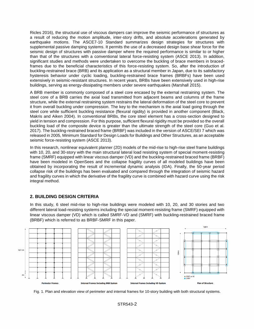
Fig. 1. Plan and elevation view of perimeter and internal frames for 10-story building with both structural systems.
STR543-3
As shown in Fig. 1, only perimeter frames were SMRF, only three middle spans were SMRF in the perimeter frames, and all the beam-to-column joints of the inner members, which were under gravitational loading, were pinned. Furthermore, viscous dampers (VDs) and buckling-restrained braces (BRBs) are located in the internal frame with diagonal installation scheme as are schematically presented in Figure 1 for 10-story structure and for other models with 20-story and 30-story are identical. Also, the buildings were regular and symmetric, all the floors were assumed to act as the rigid diaphragm, the span length is 6 m, and each story has a constant height equal to 3.5 m except that the first floor which has a height equal to 4 m. In order to design the members of both structural lateral load resisting systems and seismic considerations, AISC 360 and AISC 341 codes were used, respectively (FEMA-450 2003; Hwang et al. 2008).
Furthermore, ASCE 7–10 was used for seismic loading and design coefficients (Table 1). In addition,
Chapter 18 of ASCE 7–10 was used to design the structures with a damper. Also, steel material was taken
as ST52 (Fy = 3500 kg/cm2) for structural members except for BRB members which were taken as ST37
with yield strength equal to 2400 kg/cm2. Site specifications were extracted from USGS website introduced
by ASCE 7–10 and were from San Francisco, The USA, and the soil is considered as Site Class D with the
details given in Table 2 (ASCE 2013).
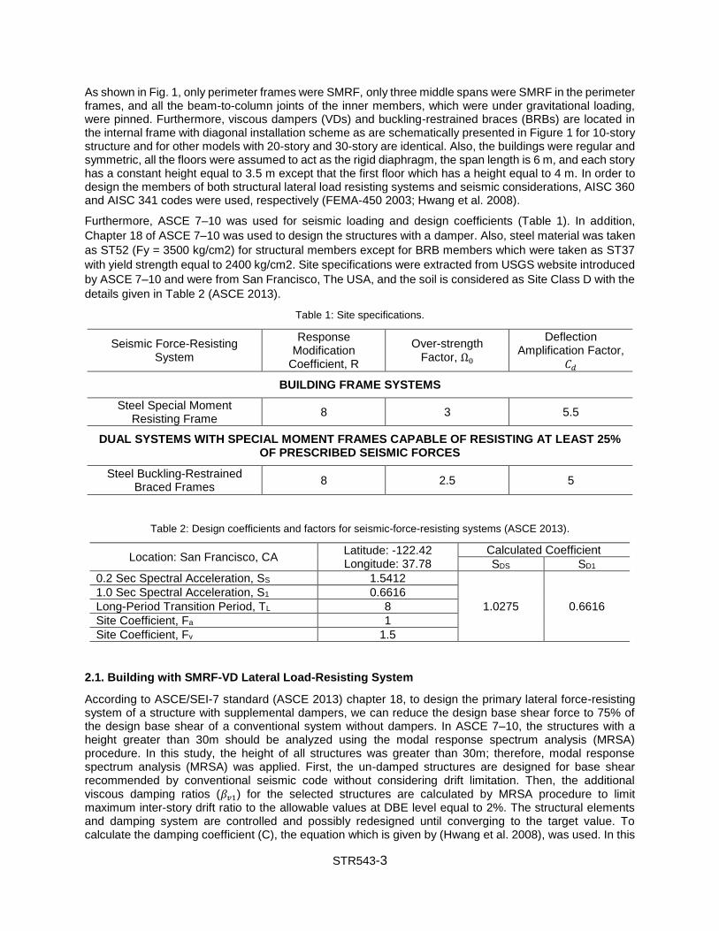
Table 1: Site specifications.
Deflection Amplification Factor,
𝐶𝑑
Over-strength Factor, Ω0
Response Modification
Coefficient, R
Seismic Force-Resisting System
BUILDING FRAME SYSTEMS
5.5 3 8 Steel Special Moment
Resisting Frame
DUAL SYSTEMS WITH SPECIAL MOMENT FRAMES CAPABLE OF RESISTING AT LEAST 25% OF PRESCRIBED SEISMIC FORCES
5 2.5 8 Steel Buckling-Restrained
Braced Frames
Table 2: Design coefficients and factors for seismic-force-resisting systems (ASCE 2013).
Calculated Coefficient Latitude: -122.42 Longitude: 37.78
Location: San Francisco, CA SD1 SDS
0.6616 1.0275
1.5412 0.2 Sec Spectral Acceleration, SS
0.6616 1.0 Sec Spectral Acceleration, S1
8 Long-Period Transition Period, TL
1 Site Coefficient, Fa
1.5 Site Coefficient, Fv
2.1. Building with SMRF-VD Lateral Load-Resisting System
According to ASCE/SEI-7 standard (ASCE 2013) chapter 18, to design the primary lateral force-resisting system of a structure with supplemental dampers, we can reduce the design base shear force to 75% of the design base shear of a conventional system without dampers. In ASCE 7–10, the structures with a height greater than 30m should be analyzed using the modal response spectrum analysis (MRSA) procedure. In this study, the height of all structures was greater than 30m; therefore, modal response spectrum analysis (MRSA) was applied. First, the un-damped structures are designed for base shear recommended by conventional seismic code without considering drift limitation. Then, the additional viscous damping ratios (𝛽𝑣1) for the selected structures are calculated by MRSA procedure to limit maximum inter-story drift ratio to the allowable values at DBE level equal to 2%. The structural elements and damping system are controlled and possibly redesigned until converging to the target value. To calculate the damping coefficient (C), the equation which is given by (Hwang et al. 2008), was used. In this
STR543-4
study, the expected damping ratio for 10 and 20 story structures was assumed 20%, which was assumed 15% for the structures with 30 stories including the inherent damping ratio of 5%.
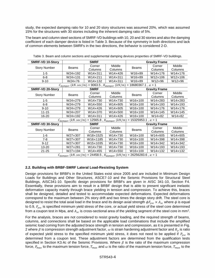
The beam and column steel sections of SMRF-VD buildings with 10, 20 and 30 stories and also the damping coefficient of each damper device is listed in Table 3. Because of the symmetry in both directions and lack of common elements between SMRFs in the two directions, the behavior is considered 2-D.
Table 3. Beam and column sections and supplemental damping devices properties of SMRF-VD buildings.
Gravity Frame SMRF SMRF-VD 10-Story
Middle Columns
Corner Columns
Beams Middle
Columns Corner
Columns Beams Story Number
W14×176 W14×176 W16×89 W14×426 W14×311 W24×192 1-5
W12×106 W12×106 W16×89 W14×311 W14×211 W24×131 6-8
W12×96 W12×96 W16×89 W14×311 W14×132 W24×76 9-10
𝐶𝑑𝑎𝑚𝑝𝑒𝑟 (𝑘𝑁. 𝑠𝑒𝑐/𝑚) = 9063.5 , 𝐾𝑑𝑎𝑚𝑝𝑒𝑟 (𝑘𝑁/𝑚) = 18680367.1 , 𝛼 = 1
Gravity Frame SMRF SMRF-VD 20-Story
Middle Columns
Corner Columns
Beams Middle
Columns Corner
Columns Beams Story Number
W14×283 W14×283 W16×100 W14×730 W14×730 W24×279 1-5
W14×193 W14×193 W16×100 W14×605 W14×550 W24×279 6-8
W14×176 W14×176 W16×100 W14×605 W14×426 W24×279 9-10
W14×145 W14×145 W16×100 W14×500 W14×370 W24×207 11-15
W14×82 W14×82 W16×100 W14×426 W14×311 W24×192 16-20
𝐶𝑑𝑎𝑚𝑝𝑒𝑟 (𝑘𝑁. 𝑠𝑒𝑐/𝑚) = 12565.8 , 𝐾𝑑𝑎𝑚𝑝𝑒𝑟 (𝑘𝑁/𝑚) = 15325953.1 , 𝛼 = 1
Gravity Frame SMRF SMRF-VD 30-Story
Middle Columns
Corner Columns
Beams Middle
Columns Corner
Columns Beams Story Number
W14×605 W14×605 W16×100 W14×730 W18×1525 W27×307 1-6
W14×398 W14×398 W16×100 W14×730 W16×1185 W27×307 7-8
W14×342 W14×342 W16×100 W14×730 W15×1035 W27×307 9-12
W14×193 W14×193 W16×100 W14×730 W14×730 W27×281 13-20
W14×132 W14×132 W16×100 W14×550 W14×455 W27×194 21-25
𝐶𝑑𝑎𝑚𝑝𝑒𝑟 (𝑘𝑁. 𝑠𝑒𝑐/𝑚) = 24458.5 , 𝐾𝑑𝑎𝑚𝑝𝑒𝑟 (𝑘𝑁/𝑚) = 26256283.6 , 𝛼 = 1
2.2. Building with BRBF-SMRF Lateral Load-Resisting System
Design provisions for BRBFs in the United States exist since 2005 and are included in Minimum Design Loads for Buildings and Other Structures, ASCE7-10 and the Seismic Provisions for Structural Steel Buildings, AISC341-10. Specific design provisions for BRBFs are given in AISC 341-10, Section F4. Essentially, these provisions aim to result in a BRBF design that is able to present significant inelastic deformation capacity mainly through brace yielding in tension and compression. To achieve this, braces shall be designed, detailed and tested to accommodate expected deformations. Expected deformations correspond to the maximum between 2% story drift and two times the design story drift. The steel core is designed to resist the total axial load in the brace and its design axial strength 𝜙𝐹𝑦𝑠𝑐 × 𝐴𝑠𝑐 where 𝜙 is equal
to 0.9, 𝐹𝑦𝑠𝑐 is specified minimum yield stress of the core, or actual yield stress of the steel core determined
from a coupon test in Mpa, and 𝐴𝑠𝑐 is cross-sectional area of the yielding segment of the steel core in mm2.
For the analysis, braces are not considered to resist gravity loading, and the required strength of beams, columns, and connections shall be based on the applicable load combinations that include the amplified seismic load coming from the adjusted brace strength in tension and compression, as it is presented in Fig. 2 where 𝛽 is compression strength adjustment factor, 𝜔 is strain hardening adjustment factor and 𝑅𝑦 is ratio
of expected yield stress to the specified minimum yield stress, it does not need to be applied if 𝑃𝑦𝑠𝑐 is
determined from a coupon test. These adjustment factors are determined from the qualification tests specified in Section K3.4c of the Seismic Provisions. Where 𝛽 is the ratio of the maximum compression
force, 𝑃𝑚𝑎𝑥 to the maximum tension force, 𝑇𝑚𝑎𝑥 and 𝜔 is the ratio of the maximum tension force, 𝑇𝑚𝑎𝑥 to the

STR543-5
measured yield force, 𝑅𝑦𝑃𝑦𝑠𝑐 . Due to the test configuration, these maximums occur at 2.0∆𝑏𝑚, where ∆𝑏𝑚
is the design story drift, as shown in Fig. 2. Finally, beams and columns shall satisfy the requirements for highly ductile members.
In addition, ASCE7-10 includes Dual Systems, consisting of a BRBF and a SMRF, as an option for Seismic Force-Resisting Systems (SFRS). The first prototype design for dual systems was based on the ASCE7-10 requirement, the BRBF was proportioned to resist the full design base shear and the SMRF was sized for 25 percent of the design seismic forces applied to the BRBF. Modal response spectrum analysis (MRSA) was also used for the design of dual systems and the BRBF designs still included P-Δ effects. The SMRF design was performed in accordance with AISC Seismic Provisions. The beam and column steel sections of BRBF-SMRF buildings with 10, 20 and 30 stories and also the BRB members are listed in Table 4.
Figure 2. Diagram of brace force-displacement (Adapted from AISC 2010).
Table 4. Beam, column and BRB sections of BRBF-SMRF buildings.
BRBF SMRF BRBF-SMRF 10-Story
BRB Columns Beams Middle
Columns Corner
Columns Beams Story Number
StarBRB_18.0 W14×370 W16×89 W14×132 W14×132 W16×57 1
StarBRB_14.0 W14×342 W16×89 W14×132 W14×132 W16×57 2-3
StarBRB_14.0 W14×211 W16×89 W14×132 W14×132 W16×57 4
StarBRB_12.0 W14×176 W16×89 W12×96 W12×96 W16×40 5-7
StarBRB_12.0 W14×145 W16×89 W12×96 W12×96 W16×40 7
StarBRB_18.0 W14×370 W16×89 W12×96 W12×96 W16×40 8-10
BRBF SMRF BRBF-SMRF 20-Story
BRB Columns Beams Middle
Columns Corner
Columns Beams Story Number
StarBRB_23.0 W15×1035 W16×100 W14×342 W14×342 W18×158 1-3
StarBRB_18.0 W14×730 W16×100 W14×342 W14×342 W18×158 4-5
StarBRB_18.0 W14×605 W16×100 W14×311 W14×311 W18×158 6-9
StarBRB_16.0 W14×426 W16×100 W14×233 W14×233 W18×130 10-12
StarBRB_12.0 W14×283 W16×100 W14×233 W14×233 W18×130 13-15
StarBRB_8.0 W14×132 W16×100 W14×176 W14×176 W18×97 16-18
StarBRB_8.0 W14×74 W16×100 W14×176 W14×176 W18×97 19-20
BRBF SMRF BRBF-SMRF 30-Story
BRB Columns Beams Middle
Columns Corner
Columns Beams Story Number
StarBRB_30.0 W15×1035 W16×100 W14×605 W14×605 W18×192 1-3
StarBRB_30.0 W14×770 W16×100 W14×550 W14×550 W18×192 4-5
StarBRB_30.0 W14×730 W16×100 W14×550 W14×550 W18×192 6-7
StarBRB_24.0 W14×605 W16×100 W14×426 W14×426 W18×192 8-11
StarBRB_24.0 W14×500 W16×100 W14×370 W14×370 W18×175 12-13
StarBRB_20.0 W14×455 W16×100 W14×370 W14×370 W18×175 14-15
StarBRB_20.0 W14×398 W16×100 W14×342 W14×342 W18×175 16-17
STR543-6
StarBRB_16.0 W14×342 W16×100 W14×342 W14×342 W18×175 18-19
StarBRB_14.0 W14×283 W16×100 W14×257 W18×106 W14×257 20-24
StarBRB_12.0 W14×159 W16×100 W14×211 W18×106 W14×211 25-30
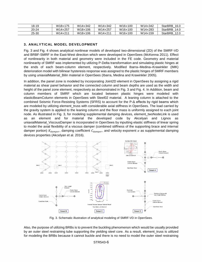
3. ANALYTICAL MODEL DEVELOPMENT
Fig. 3 and Fig. 4 shows analytical nonlinear models of developed two-dimensional (2D) of the SMRF-VD
and BRBF-SMRF in the East-West direction which were developed in OpenSees (McKenna 2011). Effect
of nonlinearity in both material and geometry were included in the FE code. Geometry and material
nonlinearity of SMRF was implemented by utilizing P-Delta transformation and simulating plastic hinges at
the ends of each beam-column element, respectively. Modified Ibarra–Medina–Krawinkler (IMK)
deterioration model with bilinear hysteresis response was assigned to the plastic hinges of SMRF members
by using uniaxialMaterial_Bilin material in OpenSees (Ibarra, Medina and Krawinkler 2005).
In addition, the panel zone is modeled by incorporating Joint2D element in OpenSees by assigning a rigid
material as shear panel behavior and the connected column and beam depths are used as the width and
height of the panel zone element, respectively as demonstrated in Fig. 3 and Fig. 4. In Addition, beam and
column members of SMRF which are located between plastic hinges were modeled with
elasticBeamColumn elements in OpenSees with Steel02 material. A leaning column is attached to the
combined Seismic Force-Resisting Systems (SFRS) to account for the P-Δ effects by rigid beams which
are modeled by utilizing element_truss with considerable axial stiffness in OpenSees. The load carried by
the gravity system is applied to the leaning column and the floor mass is uniformly assigned to each joint
node. As illustrated in Fig. 3, for modeling supplemental damping devices, element_twoNodeLink is used
as an element and for material the developed code by Akcelyan and Lignos as
uniaxialMaterial_ViscousDamper is incorporated in OpenSees by inputting elastic stiffness of linear spring
to model the axial flexibility of a viscous damper (combined stiffness of the supporting brace and internal
damper portion) 𝐾𝑑𝑎𝑚𝑝𝑒𝑟, damping coefficient 𝐶𝑑𝑎𝑚𝑝𝑒𝑟, and velocity exponent 𝛼 as supplemental damping
devices properties (Akcelyan et al. 2016).
Fig. 3. Schematic illustration of analytical modeling of SMRF-VD in OpenSees.
Also, the purpose of utilizing BRBs is to prevent the buckling phenomenon which would be usually provided
by an outer steel restraining tube supporting the yielding steel core. As a result, element_truss is utilized
for modeling the BRBs because it cannot buckle and there is no need to model the outer steel restraining

STR543-7
tube be since its effect is indirectly intended. To model the whole BRB, it is sufficient to incorporate the
element_truss command and assign the cross-section and specifications of the steel yielding core to the
element. The nonlinear behavior of BRBs are modeled by utilizing uniaxialMaterial_Steel04 which have
recently been introduced by Zsarnóczay as material (Zsarnóczay and Vigh 2017). Finally, the BRBF and
damping system consists of a couple of one-bay frames are connected to both sides of the SMRF by rigid
beams pinned at both ends respectively to complete two-dimensional (2D) models of the SMRF-VD and
BRBF-SMRF buildings (Safaei et al. 2019).
Fig. 4. Schematic illustration of analytical modeling of BRBF-SMRF in OpenSees.
4. INCREMENTAL DYNAMIC ANALYSIS (IDA)
The seismic performance of the SMRF-VD and BRBF-SMRF models is assessed utilizing incremental
dynamic analysis (IDA) (Vamvatsikos and Cornell 2002). IDA is a method in which the intensity measure
(IM) value is systematically increased from a small initial quantity until the damage measure (DM) value
exceeds to the point where the model collapses under the lateral seismic forces. The “Hunt and Fill”
algorithm was incorporate for this process (Vamvatsikos 2011). For performing an IDA, one of the most
crucial considerations is to choose an appropriate intensity measure (IM) and damage measure (DM). In
this study, 5% damped first mode spectral acceleration, 𝑆𝑎[𝑇1] and maximum inter-story drift ratio, 𝜃𝑚𝑎𝑥
were chosen as IM and DM, respectively. During the IDAs, collapse is taken as the point at which the IDA
curve slope reduced to 20% of the elastic slope, dynamic instability occurs or a drift limit of 10% for SMRF-
VD and BRBF-SMRF models is exceeded. This assumption is consistent with Table 4–10 of the SAC report,
which states that collapse prevention performance is broken when the story drift exceeds 10% (Lignos and
Krawinkler 2013).
The set of 44 (22 pairs) far-field ground motion records specified in FEMA P695 are used. The magnitude
for these records varies from M6.5 to M7.6 with an average of M7.0. Thirty-two (16 pairs) of the ground
motions were recorded at sites classified as site class D and the remaining records are from site class C
locations. The peak ground acceleration for the record set varies from 0.21g to 0.82g with an average of
0.43g. More detailed information about the ground motion records can be found in Appendix of FEMA P695.
Scaling for IDAs is performed such that the median spectral acceleration of the record set matches the
specified intensity levels, which ranges from 0.2g to 3.0g (FEMA P58-1. 2012). The results of IDA curves
for the 10, 20, and 30-story SMRF-VD and BRBF-SMRF models are shown in Fig. 5.

STR543-8
Fig. 5. IDA curves for the 10, 20, and 30-story SMRF-VD and BRBF-SMRF models.
5. FRAGILITY CURVES AND RISK ASSESSMENT OF STRUCTURES
The IDA results are used to obtain fragilities for the SMRF-VD and BRBF-SMRF models. Fragility functions
are used to quantify the probability that the structure will exceed a particular damage state as a function of
some intensity measure (IM). In this study, the probability of collapse on the spectral acceleration level at
the 1st mode period is determined from the IDA results. The fragility curve is a cumulative distribution
function of median collapse spectral acceleration from individual records. The collapse fragility curve is
assumed to follow approximately a cumulative lognormal distribution (Vamvatsikos and Cornell 2002;
Bradley and Dhakal 2008).
Fig. 5 shows the collapse fragility curves for the 10, 20, and 30-story SMRF-VD and BRBF-SMRF buildings.
As expected, by increasing the height of buildings and subsequently increasing the P-Δ effect under far-
field earthquakes, the probability of collapse raised. In the comparison between the structures with SMRF-
VD and BRBF-SMRF, the probability of collapse was smaller in the structures with dual systems than the
structures with supplemental damping systems.
Although, the 50-year collapse risk of structures with both Seismic Force-Resisting Systems (SFRS) has
been calculated through the integration of seismic hazard and fragility curves in which the derivative of
fragility curve is combined with hazard curve using the risk integral (Judd and Charney 2014). According to
Fig. 7, The results indicated that the 50-year collapse risk for the 10, 20, and 30-story models with BRBF-
SMRF system is equal to 2.25%, 6.15%, and 10.24% respectively. However, this ratio is about 2.94%,
7.43%, and 12.02% for 10, 20, and 30-story models with SMRF-VD system.

STR543-9
Fig. 6. Collapse fragility curves for the 10, 20, and 30-story SMRF-VD and BRBF-SMRF models.
6. CONCLUSION
A comparative assessment of the collapse risk for the 10, 20, and 30-story SMRF-VD and BRBF-SMRF is
presented. Firstly, analytical models of designed 10, 20, and 30-story office buildings with both Seismic
Force-Resisting Systems (SFRS) were developed in OpenSees. Secondly, incremental dynamic analysis
(IDA) was performed to study the response of the modeled buildings. Based on the results which are shown
in Fig. 7 it can be concluded that the collapse risk of buildings with higher height is considerably greater
than that of the building with a lower height. More specifically, the 50-year collapse risk of 10, 20, and 30-
story BRBF-SMRF buildings are 23.4%, 17.2%, and 14.8% lower compared to SMRF-VD buildings with
identical height respectively. As a result, it can be inferred that the seismic performance of BRBF-SMRF
dual system toward controlling the collapse risk is more superior compared to SMRF-VD system. However,
the collapse risk of both systems gets more close together by increasing the height of buildings.
Fig. 7. Comparison of 50-year collapse risk for the 10, 20, and 30-story models with SMRF-VD and BRBF-SMRF
systems based on derivative of fragility curve method (Judd and Charney 2014).
REFERENCES
American Society of Civil Engineers & American Society of Civil Engineers. (2013). “Minimum Design Loads for Buildings and Other Structures”. American Society of Civil Engineers.
Akcelyan, Sarven, Dimitrios G. Lignos, Tsuyoshi Hikino, and Masayoshi Nakashima. 2016. "Evaluation of Simplified and State-Of-The-Art Analysis Procedures for Steel Frame Buildings Equipped with

STR543-10
Supplemental Damping Devices Based On E-Defense Full-Scale Shake Table Tests". Journal of Structural Engineering 142 (6): 04016024. doi:10.1061/(asce)st.1943-541x.0001474.
Bertero, Raul D., and Vitelmo V. Bertero. 2002. "Performance-Based Seismic Engineering: The Need for A Reliable Conceptual Comprehensive Approach". Earthquake Engineering & Structural Dynamics 31 (3): 627-652. doi:10.1002/eqe.146.
Black, Cameron J., Nicos Makris, and Ian D. Aiken. 2004. "Component Testing, Seismic Evaluation and Characterization of Buckling-Restrained Braces". Journal of Structural Engineering 130 (6): 880-894. doi:10.1061/(asce)0733-9445(2004)130:6(880).
Bradley, Brendon A., and Rajesh P. Dhakal. 2008. "Error Estimation of Closed-Form Solution for Annual Rate of Structural Collapse". Earthquake Engineering & Structural Dynamics 37 (15): 1721-1737. doi:10.1002/eqe.833.
Dong, Baiping, Richard Sause, and James M. Ricles. 2016. "Seismic Response and Performance of a Steel MRF Building with Nonlinear Viscous Dampers Under DBE and MCE". Journal of Structural Engineering 142 (6): 04016023. doi:10.1061/(asce)st.1943-541x.0001482.
FEMA 450. (2003). NEHRP Recommended Provisions for Seismic Regulations for New Buildings and Other Structures. Federal Emergency Management Agency.
FEMA P58-1. 2012. “Seismic Performance Assessment of Buildings”. Applied Technology Council, Redwood City, CA.
Guo, Yan-Lin, Jing-Zhong Tong, Xiao-An Wang, and Bo-Hao Zhang. 2017. "Subassemblage Tests and Numerical Analyses of Buckling-Restrained Braces Under Pre-Compression". Engineering Structures 138: 473-489. doi:10.1016/j.engstruct.2017.02.046.
Hwang, Jenn-Shin, Yin-Nan Huang, Shy-Lian Yi, and Song-Yen Ho. 2008. "Design Formulations for Supplemental Viscous Dampers to Building Structures". Journal of Structural Engineering 134 (1): 22-31. doi:10.1061/(asce)0733-9445(2008)134:1(22).
Ibarra, Luis F., Ricardo A. Medina, and Helmut Krawinkler. 2005. "Hysteretic Models That Incorporate Strength and Stiffness Deterioration". Earthquake Engineering & Structural Dynamics 34 (12): 1489-1511. doi:10.1002/eqe.495.
Judd, J.P. and Charney, F.A. 2014. “Earthquake Risk Analysis of Structures”. Proceedings of the 9th International Conference on Structural Dynamics. EURODYN, 2929-2938.
Lignos, D and Krawinkler, H. 2013. “Sidesway Collapse of Deteriorating Structural Systems Under Seismic Excitations”. John A. Blume Earthquake Engineering Center Technical Report 177. Stanford Digital Repository. Available at: http://purl.stanford.edu/yg701cw5473.
Marshall, Justin D. 2015. "Buckling-Restrained Braces and Their Implementation in Structural Design of Steel Buildings". Encyclopedia of Earthquake Engineering, 1-11. doi:10.1007/978-3-642-36197-5_313-1.
McKenna, Frank. 2011. "Opensees: A Framework for Earthquake Engineering Simulation". Computing in Science & Engineering 13 (4): 58-66. doi:10.1109/mcse.2011.66.
Molina Hutt, Carlos, Ibrahim Almufti, Michael Willford, and Gregory Deierlein. 2016. "Seismic Loss and Downtime Assessment of Existing Tall Steel-Framed Buildings and Strategies for Increased Resilience". Journal of Structural Engineering 142 (8). doi:10.1061/(asce)st.1943-541x.0001314.
Safaei, Shayan, Arsam Taslimi, and Payam Tehrani. 2019. “A Study on the Accuracy of Force Analogy Method in Nonlinear Static Analysis.” The Structural Design of Tall and Special Buildings 28 (13). doi:10.1002/tal.1654.
Vamvatsikos, Dimitrios, and C. Allin Cornell. 2002. "Incremental Dynamic Analysis". Earthquake Engineering & Structural Dynamics 31 (3): 491-514. doi:10.1002/eqe.141.
Vamvatsikos, Dimitrios. 2011. "Performing Incremental Dynamic Analysis in Parallel". Computers & Structures 89 (1-2): 170-180. doi:10.1016/j.compstruc.2010.08.014.
Zaker Esteghamati, Mohsen, and Alireza Farzampour. 2020. “Probabilistic Seismic Performance and Loss Evaluation of a Multi-Story Steel Building Equipped with Butterfly-Shaped Fuses.” Journal of Constructional Steel Research 172: 106187. doi:10.1016/j.jcsr.2020.106187.
Zsarnóczay, Ádám, and László Gergely Vigh. 2017. "Eurocode Conforming Design of BRBF – Part II: Design Procedure Evaluation". Journal of Constructional Steel Research 135: 253-264. doi:10.1016/j.jcsr.2017.04.013.