collaborative bim-based work˜ows for a new sustainable
TRANSCRIPT
Universidade do MinhoEscola de Engenharia
Lombe Mutale
Collaborative BIM-based work�ows for a new sustainable compression-only structural block construction system
september 2021UM
inho
| 20
21Lo
mbe
Mut
ale
Colla
bora
tive
BIM
-bas
ed w
ork�
ows
for a
new
sus
tain
able
com
pres
sion
-onl
y st
ruct
ural
blo
ck c
onst
ruct
ion
syst
em
Co-funded by the Erasmus+ Programme of the European Union
The European Master in Building Information Modelling is a joint initiative of:

Universidade do Minho Escola de Engenharia
Lombe Mutale Collaborative BIM-based workflows for a new sustainable compression-only structural block construction system
Master Dissertation European Master in Building Information Modelling Work conducted under supervision of: Miguel Azenha Bruno Figueiredo Carlos Gomes (Tutor in Company)
September, 2021

Collaborative BIM-based workflows for a new sustainable compression-only structural block construction system
Erasmus Mundus Joint Master Degree Programme – ERASMUS+
European Master in Building Information Modelling BIM A+ ii
AUTHORSHIP RIGHTS AND CONDITIONS OF USE OF THE WORK BY THIRD PARTIES
This is an academic work that can be used by third parties, as long as internationally accepted rules and
good practices are respected, particularly in what concerts to author rights and related matters.
Therefore, the present work may be used according to the terms of the license shown below.
If the user needs permission to make use if this work in conditions that are not part of the licensing
mentioned below, he/she should contact the author through the RepositóriUM platform of the University
of Minho.
License granted to the users of this work
Attribution
CC BY
https://creativecommons.org/licenses/by/4.0/

Collaborative BIM-based workflows for a new sustainable compression-only structural block construction system
Erasmus Mundus Joint Master Degree Programme – ERASMUS+
European Master in Building Information Modelling BIM A+ iii
ACKNOWLEDGEMENTS
I would like to express my deepest gratitude to my supervisors Professor Miguel Azenha, Professor
Bruno Figueiredo and Carlos Gomes who provided invaluable feedback and support throughout the
dissertation period.
Many thanks to the Erasmus Mundus Programme of the European Union for the provision of a
scholarship that funded my studies and made my life much easier.
Thank you to Professor Nuno Mendes who provided DIANA FEA advice and support; Renato Correia
who was kind enough to allow the use of his C# script and tirelessly answered all my questions; Samuel
Ribeiro at the University of Minho Design Institute and Benedetta Boso who assisted with the creation
of the 3D printed prototype and photo montage and patiently made sure we got it right.
Further thanks to the BIM A+ staff and my fellow students in the BIM A+ 2020/2021 cohort for a
memorable year, that was more than I could have ever imagined and will always cherish.
Last by not least, special thanks to my family and friends for their continuous support and
encouragement.

Collaborative BIM-based workflows for a new sustainable compression-only structural block construction system
Erasmus Mundus Joint Master Degree Programme – ERASMUS+
European Master in Building Information Modelling BIM A+ iv
STATEMENT OF INTEGRITY
I hereby declare having conducted this academic work with integrity. I confirm that I have not used
plagiarism or any form of undue use of information or falsification of results along the process leading
to its elaboration.
I further declare that I have fully acknowledged the Code of Ethical Conduct of the University of Minho.
Lombe Mutale

Collaborative BIM-based workflows for a new sustainable compression-only structural block construction system
Erasmus Mundus Joint Master Degree Programme – ERASMUS+
European Master in Building Information Modelling BIM A+ v
RESUMO
Atualmente, a indústria da construção é a maior do mundo, sendo responsável por 8% das emissões de
gases de efeito estufa, principalmente devido ao betão, que é o material mais comum usado na construção.
O betão armado recorre a armaduras em aço, que estão particularmente sujeitas à corrosão quando ocorre
fissuração e decorrente penetração de agentes agressivos do exterior. A corrosão generalizada do aço afeta
a durabilidade de toda a estrutura, reduz sua vida útil e aumenta a necessidade de reabilitação e manutenção
durante seu ciclo de vida. Uma alternativa interessante, em prol da otimização, durabilidade e minimização
do desperdício de material, conceber estruturas de betão unicamente sujeitas a esforços de compressão e,
evitando portanto a necessidade de utilização de armaduras. Isso pode ser alcançado através da aplicação
de métodos de otimização da forma da estrutura. É também sabido que os sistemas pré-fabricados
permitem otimização e aumento de produtividade na indústria da construção, por comparação com os
métodos tradicionais de construção in-situ. Além disso, a digitalização por meio de BIM e processos de
projeto computacional podem automatizar e auxiliar na redução de custos e garantia de qualidade.
Esta dissertação propõe o uso de betão de baixa resistência para criar estruturas pré-fabricadas de betão,
sujeitas unicamente a esforços de compressão. Cada parte discreta da estrutura (módulos de cerca de um
metro quadrado de área) é feita por meio de moldes flexíveis que se adaptam a uma ampla gama de
geometrias. Os componentes estruturais são conectados por cabos de pré-esforço (em material não
metálico, evitando efeitos de corrosão) que são instalados no local, criando assim um novo sistema de
construção. Em suma, o sistema visa satisfazer os seguintes requisitos: i) ser autoportante durante a
construção, ou precisando apenas de escoramento limitado; ii) comportamento estrutural otimizado
(somente compressão - sem momentos de flexão), iii) alta durabilidade e longa vida útil (sem armaduras
metálicas).
No âmbito da dissertação são utilizados algoritmos computacionais para criar uma forma estrutural de
casca somente de compressão por meio de métodos conhecidos por ‘form finding’ no Rhinoceros /
Grasshopper 3D. Uma vez obtida a forma estrutural geral, foi-lhe atribuída espessura e compartimentação
(tecelagem), definindo assim seus elementos discretos. A sequência de construção dos elementos pré-
fabricados foi implementada automaticamente com algoritmos de automação celular. Em seguida, foi
criada uma ferramenta customizada que permite interoperabilidade automática do modelo criado para o
software de análise estrutural DIANA e automatizou a análise em fases que incorporou a sequência
construtiva. Posteriormente, foi usada a análise pelo método dos elementos finitos para avaliar o
comportamento estrutural. Por fim, é proposto um fluxo de trabalho colaborativo entre engenheiros e
arquitetos, rumo à definição conjunta de formas otimizadas com o procedimento desenvolvido nesta
dissertação.
Por meio de um estudo de caso para testar a estrutura, os resultados mostram que o fluxo de trabalho
proposto é viável, podendo ser aplicável a outras geometrias mais complexas. Refira-se que embora
existam algumas tensões de tração presentes durante a construção em fases, elas podem ser quase
eliminadas com o uso de suportes de construção provisórios (meros escoramentos tipicamente usados na
construção) com pouco impacto nos custos e tempo de construção.
Palavras-chave: método do elementos finitos, otimização de forma, interoperabilidade, pré-fabricação,
modelação paramétrica)
Collaborative BIM-based workflows for a new sustainable compression-only structural block construction system
Erasmus Mundus Joint Master Degree Programme – ERASMUS+
European Master in Building Information Modelling BIM A+ vi
ABSTRACT
Currently, the construction industry is the largest industry in the world and contributes 8% per year to
greenhouse gas emissions mostly due to concrete which is the most common material used for
construction. Reinforced concrete needs steel reinforcement which is prone to rust when the concrete
cracks and deleterious materials reach the steel. Widespread steel corrosion affects the durability of the
entire structure, reduces its service life, and increases the need for rehabilitation and maintenance during
its lifecycle. An interesting alternative, for the sake of optimisation, durability, and material waste
minimisation, would be to make concrete structures solely endure compression forces and hence avoid
the need to use steel reinforcement. This can be achieved through applying form-finding methods to
achieve optimised structural shapes. Precast systems can further optimise and increase the industry’s
productivity more than the traditional on-site construction systems can. Additionally, digitalisation
through BIM and computational design processes can automate and assist in cost savings and quality
assurance.
This dissertation proposes the use of low-strength concrete to create precast compression-only concrete
structures. Each discrete part of the structure is made through flexible moulds that are adaptable to a
wide range of geometries. The structural components are connected by prestressing cables (not made of
steel and not prone to corrosion) which are installed in-situ thereby creating a new construction system.
In short, the system aims to satisfy the following requirements i) self-supporting during construction, or
only needing some propping ii) optimised structural behaviour (compression-only – no bending
moments), iii) high durability and long service life (no reinforcement).
Computational and parametric design were used to create a compression-only shell structural shape
through the Particle Spring form-finding method in Rhinoceros/Grasshopper 3D. Once the overall
structural shape was obtained, it was thickened and tessellated thereby defining its discrete elements.
The construction sequence of precast elements was implemented automatically with a cellular automata
algorithm. Then, a custom tool was created that linked the structural shape generated to the structural
analysis software DIANA and automated the phased analysis which incorporated the construction
sequencing. Thereafter, finite element analysis (FEA) was used to assess the structural behaviour.
Finally, a collaborative workflow was set up such that engineers and architects can work together to
create the most optimal structural shape in a BIM environment.
Through a case study to evaluate the framework, results show that with the proposed workflow, any
arbitrary compression-only structural shape can be defined using form-finding principles. FEA can be
performed for structural analysis and a BIM model produced for construction. Although, there are some
tensile stresses present during the phased construction they can be almost eliminated with the use of
minimal construction supports.
Keywords: (FEA, form-finding, interoperability, modular construction, parametric modelling)

Collaborative BIM-based workflows for a new sustainable compression-only structural block construction system
Erasmus Mundus Joint Master Degree Programme – ERASMUS+
European Master in Building Information Modelling BIM A+ vii
TABLE OF CONTENTS
1. INTRODUCTION ............................................................................................................. 15
1.1. SCOPE AND MOTIVATION .............................................................................................. 15
1.2. OBJECTIVES AND METHODOLOGY .............................................................................. 17
1.3. STRUCTURE OF DISSERTATION .................................................................................... 18
2. SUSTAINABLE DESIGN AND CONSTRUCTION OF SHELL STRUCTURES USING
DIGITAL PROCESSES & TECHNOLOGIES ....................................................................... 19
2.1. INTRODUCTION ................................................................................................................. 19
2.2. THE PRINCIPLE OF PERPECTUM ................................................................................... 20
2.3. SHELL STRUCTURES ........................................................................................................ 21
2.3.1. Definition, advantages and disadvantages ..................................................................... 21
2.3.2. Form-finding methods for obtaining shell geometry ..................................................... 22
2.3.3. Structural analysis ......................................................................................................... 24
2.4. MODULAR CONSTRUCTION SYSTEMS ........................................................................ 26
2.5. DESIGN AND CONSTRUCTION OF SHELL STRUCTURES ......................................... 28
2.5.1. Computational design and parametric modelling for shell structures ........................... 28
2.5.2. Prefabricated sequential construction ............................................................................ 31
2.6. COLLABORATIVE BIM BASED WORKFLOWS ............................................................ 33
2.6.1. Digitalisation ................................................................................................................. 33
2.6.2. Computational Design, Formwork development and physical prototyping .................. 34
2.6.3. An integrated framework for multi-criteria optimization of thin concrete shells .......... 36
3. PARAMETRIC MODELLING AND COMPUTATIONAL DESIGN TOWARDS
MODEL GENERATION ......................................................................................................... 39
3.1. INTRODUCTION ................................................................................................................. 39
3.2. GEOMETRICAL CONCEPT FOR VAULT SYSTEM ....................................................... 39
3.3. OVERVIEW OF PARAMETRIC MODELLING AND COMPUTATIONAL DESIGN
WORKFLOW ................................................................................................................................... 40
3.4. IMPLEMENTATION OF THE COMPUTATIONAL DESIGN MODEL .......................... 41
3.4.1. Structural equilibrium by form-finding ......................................................................... 41
3.4.2. Thickening, tessellating and discretisation of the structure ........................................... 43
3.4.3. Generation of cable curves ............................................................................................ 45
3.4.4. Creating the assembly sequence using a cellular automata algorithm .......................... 47
3.4.5. Connection and interoperability with BIM platform including level of information need
52
3.5. 3D PRINTING ...................................................................................................................... 54
4. STRUCTURAL ANALYSIS PROCEDURES ................................................................. 57
4.1. INTRODUCTION ................................................................................................................. 57
4.2. STRUCTURAL CONCEPT OF THE CONSTRUCTION SYSTEM .................................. 57
4.2.1. Panel size and material .................................................................................................. 57
4.2.2. Post tensioning load ...................................................................................................... 58
4.2.3. Temporary supports during construction ...................................................................... 59

Collaborative BIM-based workflows for a new sustainable compression-only structural block construction system
Erasmus Mundus Joint Master Degree Programme – ERASMUS+
European Master in Building Information Modelling BIM A+ viii
4.3. INTEROPERABILITY TOOL FOR CONNECTION BETWEEN MODELLING
PLATFORM AND STRUCTURAL ANALYSIS SOFTWARE ...................................................... 59
4.4. DIANA FEA PROPERTY ASSIGNMENT AND PHASED ANALYSIS PROCEDURES 60
4.4.1. Property assignment procedure...................................................................................... 60
4.4.2. DIANA Phased Analysis ............................................................................................... 61
4.5. DIANA EXAMPLES ............................................................................................................ 62
4.5.1. Four-block model phased analysis ................................................................................ 62
4.5.2. Python scripting for DIANA ......................................................................................... 64
4.6. SCRIPT FOR PROPERTY ASSIGNMENT AND CONSTRUCTION PHASING ............. 65
5. FRAMEWORK DEFINITION AND CASE STUDY ..................................................... 67
5.1. INTRODUCTION ................................................................................................................. 67
5.2. FRAMEWORK FOR WORKFLOW WITH ARCHITECT AND STRUCTURAL
ENGINEER ....................................................................................................................................... 67
5.3. CASE STUDY OF A NEW SUSTAINABLE COMPRESSION-ONLY STRUCTURAL
BLOCK CONSTRUCTION SYSTEM ............................................................................................. 72
5.3.1. Parametric modelling ..................................................................................................... 72
5.3.2. Structural description: supports, material properties and loading ................................. 76
5.3.2.1. Boundary conditions .................................................................................................. 77
5.3.2.2. Material properties ..................................................................................................... 77
5.3.2.3. Loads ......................................................................................................................... 78
5.3.2.4. Load combinations .................................................................................................... 79
5.3.2.5. Construction scenarios considered ............................................................................ 79
5.3.3. FEA modelling and analysis .......................................................................................... 80
5.3.4. Results for Check 1: Self-weight only, no construction support and no phasing .......... 80
5.3.5. Results for Check 2: Construction phasing but no construction supports ..................... 81
5.3.6. Results for Check 3: Construction phasing and construction supports ......................... 82
5.3.6.1. Possibility of cracks during construction ................................................................... 82
5.3.6.2. Possibility of instability due to interface tensions during construction ..................... 83
5.3.6.3. Deflections and Bending moments ............................................................................ 85
5.3.7. Results for Check 4: Wind Load ................................................................................... 86
5.3.8. Results for Check 5: Snow load .................................................................................... 87
5.3.9. Photo montage of case study ......................................................................................... 88
5.4. OTHER APPLICATIONS OF FRAMEWORK ................................................................... 88
5.4.1. Exhibit A ....................................................................................................................... 88
5.4.2. Exhibit B ........................................................................................................................ 90
5.4.3. Exhibit C and Photo Montage ....................................................................................... 91
6. CONCLUSION ................................................................................................................ 95
REFERENCES......................................................................................................................... 97
LIST OF ACRONYMS AND ABBREVIATIONS .............................................................. 101
APPENDICES ....................................................................................................................... 103
APPENDIX 1: PYTHON SCRIPT FOR DIANA AUTOMATIC PROPERTY ASSIGNMENT AND
CONSTRUCTION PHASING ........................................................................................................ 103

Collaborative BIM-based workflows for a new sustainable compression-only structural block construction system
Erasmus Mundus Joint Master Degree Programme – ERASMUS+
European Master in Building Information Modelling BIM A+ ix
APPENDIX 2: DIANA MODELLING AND ANALYSIS PROCEDURE ................................... 107
APPENDIX 3: PART GRASSHOPPER CODE FOR FORM-FINDING AND SHAPE
GENERATION ............................................................................................................................... 116
Collaborative BIM-based workflows for a new sustainable compression-only structural block construction system
Erasmus Mundus Joint Master Degree Programme – ERASMUS+
European Master in Building Information Modelling BIM A+ x
LIST OF FIGURES
Figure 1 – Compression-only shell structure - Aichtal Outdoor Theatre in Germany (Adriaenssens et al.,
2014) ...................................................................................................................................................... 15
Figure 2 - Set of assembled panels as proposed by Perpectum (Azenha, 2019) ................................... 16
Figure 3 – Construction labour-productivity vs. manufacturing and total economy growth trend (Barbosa
et al., 2017) ............................................................................................................................................ 19
Figure 4 – Photo example of corrosion-induced damage on a reinforced concrete marine structure
(Alexander and Nganga, 2014) .............................................................................................................. 20
Figure 5 – Perpectum panel concept and 3D printed proofs of concept (Azenha, 2019) ...................... 21
Figure 6 – Under construction and completed shell structure at the entrance of the Universal
Oceanographic Park in Valencia, Spain (Tomás and Martí, 2010) ....................................................... 22
Figure 7 – Top and axonometric views for Form-finding example starting with a flat mesh/grid &
supports at two opposite corners (Veenendaal and Block, 2012) .......................................................... 23
Figure 8 - FEM Process (Schuster, 2017) .............................................................................................. 25
Figure 9 – The Kresge Auditorium, Cambridge, 1955, by Eero Saarinen, as of 2003, with detail of
support (Adriaenssens et al., 2014) ....................................................................................................... 25
Figure 10 - Comparison of FEM results of Kresge Auditorium As-built shell and Optimised shell using
form-finding (Goldbach et al., 2020) ..................................................................................................... 26
Figure 11 – The Striatus Bridge being built through the assembly of modules (Lomholt, 2021) ......... 27
Figure 12 - Initial plan views and final 3D shape from form-finding computation (Vizotto, 2010) ..... 29
Figure 13 – Shell optimisation with different boundary conditions (Tomás and Martí, 2010) ............. 30
Figure 14 - Result of form-finding using RhinoVAULT & Panelisation of shell (Hadilou, 2014) ...... 31
Figure 15 - Illustration of LEGO-inspired blocks and assembled structure (Bao & Li, 2020) ............. 31
Figure 16 - Lock Block Products (Lock Block, 2021) .......................................................................... 32
Figure 17 - Large precast concrete panels on a truck (Shay Murtagh, 2021) ........................................ 32
Figure 18 – Overall framework and details of computational design optimisation steps (Kontovourkis et
al., 2019) ................................................................................................................................................ 34
Figure 19 - 3D printed shell prototype with hexagonal tessellation (Adriaenssens et al., 2014) .......... 34
Figure 20 - Schematic of adaptable mould (Borg Costanzi et al., 2018) ............................................... 35
Figure 21 - Interactive and iterative thin shell pre-design process (Gomes et al., 2018) ...................... 36
Figure 22 - Parameters and constraints for form-finding for a generic rectangular shape - Top view .. 40
Figure 23 - Generative Schema of a regular 7x5 network, top view and axonometric view ................. 42
Figure 24 - Grasshopper definition for the generation of a simple relaxed mesh through Kangaroo form-
finding solver ......................................................................................................................................... 42
Figure 25 – Form-finding mesh results with 3 varying inputs, axonometric view ................................ 43
Figure 26 – 3D view of gaps between panels resulting non-smooth curve from using Panelling tools 43
Figure 27 - Generative schema: Surface fragmentation, axonometric view .......................................... 44
Figure 28 - Generative Schema: U/V Curves for Top and Bottom Surface, axonometric view ........... 44
Figure 29 – 3D structure segmented into panels and plan view with labelling ..................................... 44
Figure 30 - Panel and cable parameters and constraints ........................................................................ 45
Figure 31 - Creation and selection of cable curves in U direction, axonometric view .......................... 45
Figure 32 - Creation and selection of cable curves in V direction, axonometric view .......................... 46

Collaborative BIM-based workflows for a new sustainable compression-only structural block construction system
Erasmus Mundus Joint Master Degree Programme – ERASMUS+
European Master in Building Information Modelling BIM A+ xi
Figure 33 – Top and Bottom cable curves in U direction and labelling for each panel ........................ 46
Figure 34 – Left and Right cable curves in V direction and labelling for each panel ........................... 46
Figure 35 – Grasshopper cellular automata algorithm using the Anemone Plug-in ............................. 48
Figure 36 - Neighbours for cells based on maximum 8 neighbours and radius 1.5 .............................. 49
Figure 37 - Neighbours for cells based on maximum 4 neighbours and radius 1.0 .............................. 49
Figure 38 - Cell automata activation sequence – inner panels activated first ....................................... 50
Figure 39 - 3D and Plan View labelled with Assembly Sequence (1) .................................................. 51
Figure 40 - Cell automata activation sequence – outer panels activated first ....................................... 51
Figure 41 – Axonometric and Top View labelled with Assembly Sequence (2) .................................. 52
Figure 42 - Rhino geometry in Revit before baking, axonometric view ............................................... 52
Figure 43 - Revit geometry low level of detail, axonometric view ....................................................... 53
Figure 44 - Revit geometry with higher level of detail, axonometric view .......................................... 53
Figure 45 - 3D printed blocks before assembly .................................................................................... 54
Figure 46 - 3D printed blocks after assembly - Front view ................................................................... 54
Figure 47 - 3D printed blocks after assembly – axonometric view ....................................................... 55
Figure 48 – PT Block Free body diagram and stress interface calculations ......................................... 58
Figure 49 - Summary of conversion process of cable curves from Revit to DIANA geometry ........... 59
Figure 50 - Summary of the conversion process of a single panel from Revit to DIANA geometry ... 60
Figure 51 – DIANA example with four panels - Isometric and right view ........................................... 62
Figure 52 - DIANA Stages of construction 1 to 2 for four-panel example ........................................... 63
Figure 53 - DIANA Stages of construction 3 to 4 for four-block example ........................................... 64
Figure 54 - DIANA single panel size 1m x 1m x 0.3m, axonometric view and properties .................. 65
Figure 55 - DIANA Example block properties and Python commands ................................................ 65
Figure 56 – Part of Python script setting up properties ......................................................................... 66
Figure 57 – Framework for case study workflow ................................................................................. 68
Figure 58 - Process 1: Geometry definition .......................................................................................... 69
Figure 59 - Process 2: BIM ................................................................................................................... 70
Figure 60 - Process 3: Structural Analysis ............................................................................................ 71
Figure 61 – Preliminary sketch of Case Study from Process 1c ........................................................... 72
Figure 62 – Case study starting curves and resulting surface – Top view ............................................ 72
Figure 63 – Case study support locations, springs, and force application positions – Top view .......... 73
Figure 64 – Case study mesh and tessellated 300mm thick 3D shape – axonometric view ................. 73
Figure 65 - Case study initial order BEFORE cellular automata algorithm – Top view ...................... 74
Figure 66 - Case study final order AFTER cellular automata algorithm – Top view ........................... 75
Figure 67 - Case study – Revit model and cuttout showing PT cables, axonometric view .................. 76
Figure 68 - Case study - Screenshots of 6 assembly stages while Python script is running in DIANA 76
Figure 69 – Bottom view and axonometric view of structure with permanent supports....................... 77
Figure 70 - Bottom view showing permanent and temporary construction supports ............................ 77
Figure 71 - Wind Load regions for curved roofs according to EN 1991-1-4:2005 ............................... 78
Figure 72 - Wind values and direction as applied in DIANA ............................................................... 78
Figure 73 – Uniform Snow load added to structure in DIANA ............................................................ 79
Figure 74 - Principal Stresses S1 - Self-weight only, no construction supports or phasing .................. 81
Figure 75 - Principal Stresses S1 for Construction Stage 140 with no provisional supports ................ 81
Figure 76 – Principal Stresses S1 for Check 3 during early construction (1) ....................................... 82

Collaborative BIM-based workflows for a new sustainable compression-only structural block construction system
Erasmus Mundus Joint Master Degree Programme – ERASMUS+
European Master in Building Information Modelling BIM A+ xii
Figure 77 – Principal Stresses S1 for Check 3 during construction (2) ................................................. 83
Figure 78 – Central Interface stresses during Construction Stage 140 (1) ............................................ 84
Figure 79 – Central Interface stresses during Construction Stage 140 (2) ............................................ 84
Figure 80 – Block A Interface stresses at Construction Stage 140 ........................................................ 84
Figure 81 – Principal stresses S1 for Wind Load after construction ..................................................... 86
Figure 82 - Principal stresses S2 for Wind Load after construction ...................................................... 86
Figure 83 – Principal stresses S1 for Snow Load after construction ..................................................... 87
Figure 84 - Principal stresses S2 for Snow Load after construction ...................................................... 87
Figure 85 - Photo montage of case study, Parque da Cidade, Guimarães ............................................. 88
Figure 86 – Exhibit A: Rhino 3D results ............................................................................................... 89
Figure 87 - Exhibit A: Autodesk Revit result – 3D model .................................................................... 89
Figure 88 - Exhibit A: DIANA result – 3D model ................................................................................ 90
Figure 89 - Exhibit B: Rhino 3D result ................................................................................................. 90
Figure 90 - Exhibit B: Autodesk Revit Result ....................................................................................... 90
Figure 91 - Exhibit B: DIANA model ................................................................................................... 91
Figure 92 - Exhibit C: Panels in Rhino .................................................................................................. 91
Figure 93 - Exhibit C: Cables in Rhino ................................................................................................. 92
Figure 94 - Exhibit C: Revit model with two panels removed to show cables ...................................... 92
Figure 95 - Exhibit C: DIANA model ................................................................................................... 93
Figure 96 - Photo montage of Exhibit C - application of the framework .............................................. 93

Collaborative BIM-based workflows for a new sustainable compression-only structural block construction system
Erasmus Mundus Joint Master Degree Programme – ERASMUS+
European Master in Building Information Modelling BIM A+ xiii
LIST OF TABLES
Table 1 – Grasshopper Cellular automata algorithm task description .................................................. 47
Table 2 - Case study - Material properties of concrete and steel .......................................................... 78
Table 3 - Load combinations ................................................................................................................. 79
Table 4 – Construction scenarios .......................................................................................................... 80
Table 5 - Interface tensile stresses and forces at 5 Construction Stages ............................................... 85

Collaborative BIM-based workflows for a new sustainable compression-only structural block construction system
Erasmus Mundus Joint Master Degree Programme – ERASMUS+
European Master in Building Information Modelling BIM A+ 14
This page is intentionally left blank

Collaborative BIM-based workflows for a new sustainable compression-only structural block construction system
Erasmus Mundus Joint Master Degree Programme – ERASMUS+
European Master in Building Information Modelling BIM A+ 15
1. INTRODUCTION
1.1. Scope and motivation
Previous research showed that the construction industry is lagging in productivity and growth compared
to other industries. This can be addressed with digitalisation of processes e.g. through incorporating
Building Information Modelling (BIM) as well as the use of modular or off-site construction systems.
Advantages of this include shorter construction and operational costs; reduced construction time; fewer
unexpected costs for the client due to unforeseen issues on site; reduced energy consumption and better
structural performance (Long et al., 2014; Bertram et al., 2019).
It is well documented that the main construction material, concrete, is a major contributor to greenhouse
gas emissions (Belton, 2021). Additionally, even though no other material has been found to be more
efficient for use in construction than concrete, steel reinforcement leads to corrosion, expansion,
cracking and then deterioration of the concrete itself, thereby limiting the durability of reinforced
concrete structures. However, the use of reinforcement is compounded when concrete structures are
designed in a way that may be perceived as “unnatural”. With the use of form-finding, a “natural”
compression-only shape (see Figure 1) can be found that can limit the use of reinforcement. Such shapes
have been built before but with the aid of expensive formwork during construction (Adriaenssens et al.,
2014).
Figure 1 – Compression-only shell structure - Aichtal Outdoor Theatre in Germany (Adriaenssens
et al., 2014)
Various researchers have been looking into ways to optimise the current construction systems using
precast and/or form-finding (Dallinger and Kollegger, 2008; Pedersen, Larsen and Pigram, 2015; Borg
Costanzi et al., 2018; Bao and Li, 2020). Realisation of the right construction system will assist in
achieving the United Nation’s Sustainability Development Goals including “Sustainable Cities and
Communities” and “Industry, Innovation and Infrastructure” to build sustainable and resilient
infrastructure (United Nations, 2015).

Collaborative BIM-based workflows for a new sustainable compression-only structural block construction system
Erasmus Mundus Joint Master Degree Programme – ERASMUS+
European Master in Building Information Modelling BIM A+ 16
There is work being done into optimising concrete mix and using more sustainable materials. This can
be achieved for instance by substituting cement (whose production is carbon intensive) with fly ash from
the coal industry or the slag from blast furnaces for improved strength and durability. Another
(expensive) way is to physically capture the carbon produced during cement production and store it
elsewhere (Belton, 2021). Other prefabrication manufacturers use steel reinforcement to connect precast
elements such as the Lock Block company (Lock Block, 2021) which limits their durability.
Various limitations of the proposed design and construction systems exist as discussed forthwith. For
example one author uses a procedure for form-finding with complex textual programming that cannot
easily be followed other than by the originator (Vizotto, 2010). Some use BIM and an integrated
approach but this is limited to the conceptual design stage (Gomes et al., 2018).
Authors such as Kontovourkis et al. (2019) present a BIM-based computational design and optimisation
framework using topology optimisation and incorporating construction considerations. Although they
consider concrete modular elements, they do not consider construction supports required for shell
structures. Additionally, they make use of a non-flexible formwork mechanism that is restricted to a Y-
shaped element only (Kontovourkis, Phocas and Katsambas, 2019) unlike the flexible mould for the
formwork of shell structures proposed in other literature (Borg Costanzi et al., 2018).
More recently, the Striatus Bridge in Venice’s uses extremely large concrete modules by 3D printing
that require heavy lifting devices (Lomholt, 2021). On the other hand, Bao and Li (2020) propose the
solution for the problem of connection and ease of assembly and disassembly of precast elements using
much smaller brick-like components joined by pre-stressing cables. However, they neglect the
optimisation aspect by not considering compression-only and form-finding structures (Bao and Li,
2020).
The Perpectum concept (Azenha, 2019) theorized but not implemented in 2019, seeks to address the
problems identified. A sustainable, low-strength concrete precast compression-only structure that is
virtually self-supporting during construction, is proposed (refer to Figure 2). This is achieved through a
construction system whereby non-metallic cables connect the panels sequentially, during construction.
Moreover, the panels are proposed to be sized at 1m x 1m x 0.3m such that they only require light lifting
devices.
Figure 2 - Set of assembled panels as proposed by Perpectum (Azenha, 2019)
Collaborative BIM-based workflows for a new sustainable compression-only structural block construction system
Erasmus Mundus Joint Master Degree Programme – ERASMUS+
European Master in Building Information Modelling BIM A+ 17
The current work further develops on Perpectum and addresses limitations of current systems as detailed
in the objectives.
1.2. Objectives and methodology
This study proposes a new collaborative BIM-based, sustainable compression-only structural block
construction system. Each discrete part (block) of the structure is made through flexible moulds that are
adaptable to a wide range of geometry. The parts are connected by prestressed cables which will be
installed in-situ thereby creating a new construction system. The system further satisfies the following:
i) self-supporting or few supports during construction
ii) optimised i.e. compression-only system
iii) durable and long lasting with no steel reinforcement (prestressing cables made of a distinct non-
ferrous material).
For the purposes of evaluating the proposed construction system, the objectives of the study are as
follows:
• perform parametric modelling, computational design, and form-finding to produce a tessellated
compression-only structural shape
• define a construction sequence using cellular automata principles
• define interoperability tools between the computational design program and BIM platform as
well as between the BIM platform and (Finite Element Analysis) FEA software
• create a BIM model from the structural shape in the computational design program
• define the structural model from the BIM model and perform FEA to assess the structural
behaviour of the construction system
• define a BIM-based framework for collaborative design between the structural engineer and the
architect
Accordingly, the methodology entails the use of computational and parametric design to create a
compression-only shell structural shape through the particle spring form-finding method. Once the
overall structural shape is obtained, it is tessellated to define its discrete elements. Thereafter, FEA is
used to assess the structural behaviour based on the construction sequence. Finally, a collaborative
framework is presented such that the engineers and architects can work together to define and construct
the most optimal structural shape in a BIM environment.
It is finally remarked that this dissertation does not address the technological aspects needed for the
prefabrication of the modules for the system, neither from the point of view of the flexible moulds, nor
from the point of view of the adaptable parts needed to materialize the hollow parts for the cables to
pass.
Collaborative BIM-based workflows for a new sustainable compression-only structural block construction system
Erasmus Mundus Joint Master Degree Programme – ERASMUS+
European Master in Building Information Modelling BIM A+ 18
1.3. Structure of dissertation
The layout of the thesis is as follows. Chapter 2 presents a literature review of sustainability and
optimisation in the design and construction of shell structures. The principle of Perpectum, which was
the inspiration for this work, is presented. This is followed by a general discussion on shell structures
and modular construction systems. Next, these principles are refined and distilled with examples
incorporating BIM processes and workflows.
Chapter 3 presents the parametric modelling and computational design methodology in this study using
a simple example to explain the procedures. Rhinoceros 3D and plug-in Grasshopper 3D are used to
conduct the form-finding and create the cellular automata algorithm for obtaining the construction
sequence. A description of the connection tool from the computational design software to BIM platform
is presented. The last section of this chapter shows photos of the 3D printed version of the example.
Chapter 4 describes the interoperability tool defined for the BIM platform to structural analysis
connection. The chapter has a discussion on some of the properties to be used for the structural analysis
in the software DIANA FEA. Subsequently, the script for automating the material property assignment
and construction phasing is presented.
Chapter 5 presents the framework describing the collaborative workflow between the structural engineer
and the architect to perform the design to produce the compression-only construction system. Thereafter,
the framework is enacted with a case study including the parametric modelling, BIM, finite element
analysis and results. Other applications of the framework are also briefly presented.
Finally, Chapter 6 concludes the work and presents recommendations and future work proposals.

Collaborative BIM-based workflows for a new sustainable compression-only structural block construction system
Erasmus Mundus Joint Master Degree Programme – ERASMUS+
European Master in Building Information Modelling BIM A+ 19
2. SUSTAINABLE DESIGN AND CONSTRUCTION OF SHELL
STRUCTURES USING DIGITAL PROCESSES &
TECHNOLOGIES
2.1. Introduction
In recent decades, the construction industry has been criticized due to its continued use of high energy-
consuming materials such as steel and concrete in a manner that is wasteful and neither optimised nor
sustainable thereby limiting its productivity (Ribeirinho et al., 2020; Belton, 2021; Webb, 2021).
Moreover, unlike other manufacturing industries that have embraced digitisation and automation, the
construction industry lags behind and has made little progress on this front (Barbosa et al., 2017). As a
result, the construction industry has been limiting itself in terms of productivity and growth thereby
lagging far behind the manufacturing sector as well as the total economy trend as shown in Figure 3.
Figure 3 – Construction labour-productivity vs. manufacturing and total economy growth trend
(Barbosa et al., 2017)
The construction index of real gross value added per hour worked, only improved from 100 in 1995 to
110 in 2014, while manufacturing improved from 100 to almost 200 in the same time frame. Similarly,
the compound annual growth rate for manufacturing was 2.6% higher than for construction in the same
period. In fact, according to a study by the McKinsey Global Institute think tank (Ribeirinho et al.,
2020), the construction industry contributes 8% per year to greenhouse gas emissions compared to the
aviation industry’s much lower 2.5% (Ribeirinho et al., 2020; Belton, 2021).
Other critical aspects of modern construction materials are their durability and life cycle. For instance,
concrete has been the main material used for construction (Belton, 2021). The reason for this is its
mechanical properties and ease of production and ability to be moulded to the desired geometry.
Although some concrete structures such as the Pantheon in Rome, Italy have been standing for more
than 2000 years, modern concrete structures require the use of steel reinforcement in addition to the
concrete to resist external loading effects. The problem is that steel reinforcement is prone to rust and
this can happen when the concrete cracks and there is ingress of deleterious materials that reach the steel
Manufacturing
Construction
Construction
Collaborative BIM-based workflows for a new sustainable compression-only structural block construction system
Erasmus Mundus Joint Master Degree Programme – ERASMUS+
European Master in Building Information Modelling BIM A+ 20
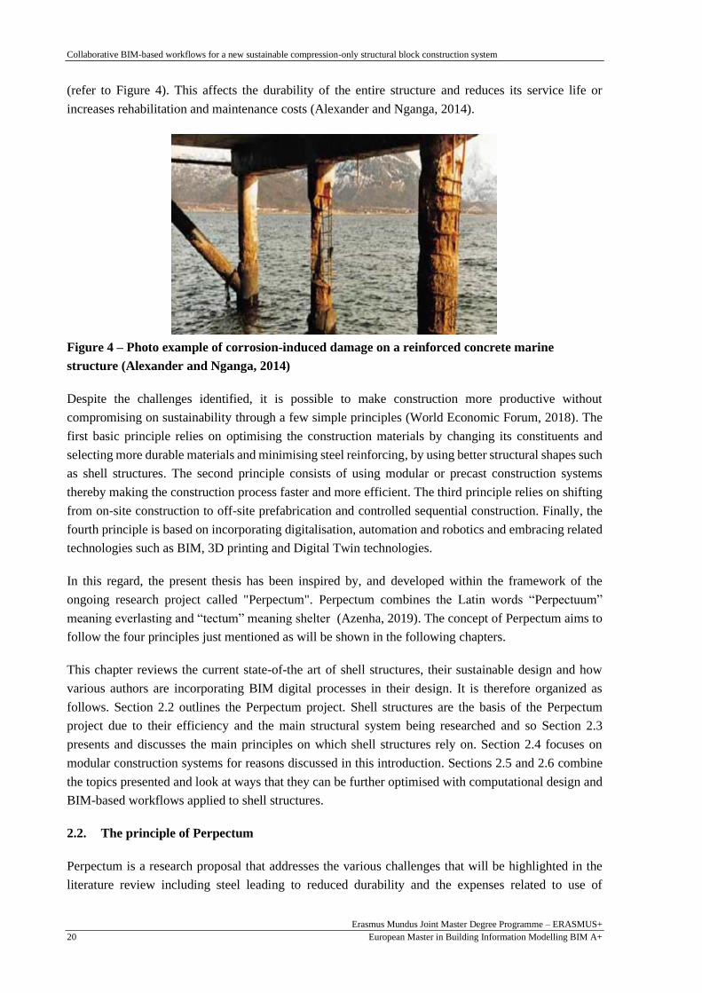
(refer to Figure 4). This affects the durability of the entire structure and reduces its service life or
increases rehabilitation and maintenance costs (Alexander and Nganga, 2014).
Figure 4 – Photo example of corrosion-induced damage on a reinforced concrete marine
structure (Alexander and Nganga, 2014)
Despite the challenges identified, it is possible to make construction more productive without
compromising on sustainability through a few simple principles (World Economic Forum, 2018). The
first basic principle relies on optimising the construction materials by changing its constituents and
selecting more durable materials and minimising steel reinforcing, by using better structural shapes such
as shell structures. The second principle consists of using modular or precast construction systems
thereby making the construction process faster and more efficient. The third principle relies on shifting
from on-site construction to off-site prefabrication and controlled sequential construction. Finally, the
fourth principle is based on incorporating digitalisation, automation and robotics and embracing related
technologies such as BIM, 3D printing and Digital Twin technologies.
In this regard, the present thesis has been inspired by, and developed within the framework of the
ongoing research project called "Perpectum". Perpectum combines the Latin words “Perpectuum”
meaning everlasting and “tectum” meaning shelter (Azenha, 2019). The concept of Perpectum aims to
follow the four principles just mentioned as will be shown in the following chapters.
This chapter reviews the current state-of-the art of shell structures, their sustainable design and how
various authors are incorporating BIM digital processes in their design. It is therefore organized as
follows. Section 2.2 outlines the Perpectum project. Shell structures are the basis of the Perpectum
project due to their efficiency and the main structural system being researched and so Section 2.3
presents and discusses the main principles on which shell structures rely on. Section 2.4 focuses on
modular construction systems for reasons discussed in this introduction. Sections 2.5 and 2.6 combine
the topics presented and look at ways that they can be further optimised with computational design and
BIM-based workflows applied to shell structures.
2.2. The principle of Perpectum
Perpectum is a research proposal that addresses the various challenges that will be highlighted in the
literature review including steel leading to reduced durability and the expenses related to use of

Collaborative BIM-based workflows for a new sustainable compression-only structural block construction system
Erasmus Mundus Joint Master Degree Programme – ERASMUS+
European Master in Building Information Modelling BIM A+ 21
formwork when constructing shells and free-form structures. Perpectum results in a more efficient and
cost-effective construction by using i) sustainable concrete with no rebar thereby avoiding corrosion and
leading to indefinite durability ii) customisable moulds for concrete structural panels iii) permanent pre-
stressing cables, and iv) Integrated Project Delivery (Azenha, 2019).
Perpectum proposes the use of prefabricated concrete panels without rebar which are produced from
customisable moulds. The panels can then be constructed sequentially using pre-stressed cables to
produce compression-only free form shell structures – refer to Figure 5.
Figure 5 – Perpectum panel concept and 3D printed proofs of concept (Azenha, 2019)
The member connection is partly inspired by Dallinger & Kollegger (2008) who proposed precast textile
reinforced concrete panels constructed using post-tensioning cables that pass-through ducts in the
panels. The pre-stressing ensures stability during construction without the need for extensive and
complex formwork or construction supports. Theoretically, this pre-loading would result in the structure
being in compression with minimal deformation that acts like a single monolithic structure despite being
made up of separate panels. Emphasis has also been placed on having enough pre-stress such that there
is no tension at the interface between the panels which would cause instability of the structure (Dallinger
and Kollegger, 2008). Additionally, the pre-stressing cables are not steel but rather maritime cables that
are non-corrodible and will therefore be highly durable (Azenha, 2019). These principles will be
expanded on further in the chapters that follow.
2.3. Shell structures
2.3.1. Definition, advantages and disadvantages
Shell structures are large with a thickness much smaller than their other dimensions. They transmit
forces primarily through a membrane action rather than bending moments. The advantages of shell
structures are that, first, they are aesthetically pleasing, natural looking forms. Secondly, large open
spaces and areas can be created without the need to use supports in between them. Third, due to their
thinness, use of the membrane action and the high strength to weight ratio, the design is more efficient,
and less material can be used, thereby making them more environmentally friendly (Adriaenssens et al.,
2014; Zingoni and Enoma, 2020).

Collaborative BIM-based workflows for a new sustainable compression-only structural block construction system
Erasmus Mundus Joint Master Degree Programme – ERASMUS+
European Master in Building Information Modelling BIM A+ 22
However, shell structures, particularly concrete ones, have some disadvantages which have led to their
decline in use and popularity. The main reason for this is, the cost of the formwork which can be as
much as a third of the total concrete cost on the project or 15% of the total construction cost. This cost
is usually due to the difficulty and complexity in setting up and dismantling the intricate formwork and
scaffolding (Nassar and Aly, 2012; Zingoni and Enoma, 2020) and is therefore significantly increased
when it comes to shapes from form-finding processes (Tomás and Martí, 2010; Kontovourkis, Phocas
and Katsambas, 2019) as shown in Figure 6.
Figure 6 – Under construction and completed shell structure at the entrance of the Universal
Oceanographic Park in Valencia, Spain (Tomás and Martí, 2010)
Nonetheless, nowadays, innovative options for customisable formwork are being considered with the
help of technology, computational design and inspired by the textile industry, but these are yet to become
mainstream (Borg Costanzi et al., 2018; Popescu et al., 2021). Alternatively, there are suggestions to
have dual purpose shell structures to justify the cost of the formwork (Zingoni and Enoma, 2020).
Another disadvantage is that if the shell is too thin, buckling problems can arise. Studies suggest that
this issue can be overcome by increasing the shell thickness, using a material with a higher elastic
modulus or increasing the geometric curvatures (Tomás and Martí, 2010). The other challenge is how
to produce the geometry of a shell structure that ensures optimal structural behaviour. This is where
form-finding comes in.
2.3.2. Form-finding methods for obtaining shell geometry
There are two main methods to design a shell structure with a funicular shape. The first concerns the
use of mathematical formulas that lead to the definition of geometries based on parabolas, spheres etc.
However, if these “unnatural” shapes are used, extra reinforcement or edge beams are required to
overcome the hoop stresses experienced in some areas and avoid excessive cracking during the life of
the structure. The second method uses form-finding processes either from numerical means or by
physical models as was popularised by Heinz Isler and Antoni Gaudí. The latter method creates tension-
only geometries which can be inverted to create compression-only geometries inspired by Richard
Waller’s statement “As hangs the flexible line, so but inverted will stand the rigid arch” and Hooke’s
law of inversion. However, although useful for visualisation and conceptual design purposes, physical
models have the limitation that the forces on the structure depend on the material and this cannot be
easily factored into the process and therefore numerical calculations are required for verification. The
alternative would be to create a scale replica of the structure, but this would be expensive. Advantages
Collaborative BIM-based workflows for a new sustainable compression-only structural block construction system
Erasmus Mundus Joint Master Degree Programme – ERASMUS+
European Master in Building Information Modelling BIM A+ 23
of form-finding using numerical means are that it allows the consideration of material properties,
computational design can be used, and more shapes can be found (Veenendaal and Block, 2012;
Adriaenssens et al., 2014; Zingoni and Enoma, 2020).
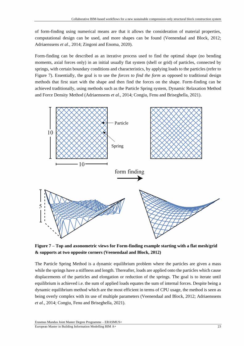
Form-finding can be described as an iterative process used to find the optimal shape (no bending
moments, axial forces only) in an initial usually flat system (shell or grid) of particles, connected by
springs, with certain boundary conditions and characteristics, by applying loads to the particles (refer to
Figure 7). Essentially, the goal is to use the forces to find the form as opposed to traditional design
methods that first start with the shape and then find the forces on the shape. Form-finding can be
achieved traditionally, using methods such as the Particle Spring system, Dynamic Relaxation Method
and Force Density Method (Adriaenssens et al., 2014; Congiu, Fenu and Briseghella, 2021).
Figure 7 – Top and axonometric views for Form-finding example starting with a flat mesh/grid
& supports at two opposite corners (Veenendaal and Block, 2012)
The Particle Spring Method is a dynamic equilibrium problem where the particles are given a mass
while the springs have a stiffness and length. Thereafter, loads are applied onto the particles which cause
displacements of the particles and elongation or reduction of the springs. The goal is to iterate until
equilibrium is achieved i.e. the sum of applied loads equates the sum of internal forces. Despite being a
dynamic equilibrium method which are the most efficient in terms of CPU usage, the method is seen as
being overly complex with its use of multiple parameters (Veenendaal and Block, 2012; Adriaenssens
et al., 2014; Congiu, Fenu and Briseghella, 2021).
Particle
Spring

Collaborative BIM-based workflows for a new sustainable compression-only structural block construction system
Erasmus Mundus Joint Master Degree Programme – ERASMUS+
European Master in Building Information Modelling BIM A+ 24
The Force Density Method is a geometric stiffness method whose underlying principle is the force
density or tension coefficient which equates to force divided by the length of a bar. The method makes
use of a linear system of equations. It initially involves the definition of the boundary conditions and the
typology; this is followed by the definition of the force densities and the loads. These inputs are then
used to calculate the displacements. The process is iterated until equilibrium is found. The method has
the advantage that the material stiffnesses and properties considered are only considered at the end which
makes it easier to compute. Nevertheless, the method has been criticised as not being constructable and
being only suitable for preliminary purposes. Another criticism is that the “force density” coefficient is
not an intuitive parameter compared to other well-known parameters such as forces (Veenendaal and
Block, 2012; Adriaenssens et al., 2014).
The Dynamic Relaxation Method was invented by Alistair Day. It is also a dynamic equilibrium method
that makes use of nonlinear equations and the principle of Kinetic Energy (KE) with the nodes initially
at rest (velocity, v = 0) and the KE = 0. Then a load is introduced to the system which leads to residual
forces which depend on the axial forces and shear forces and leads to a new velocity and kinetic energy
for each node. This is then used to calculate the new KE in the system and the process is repeated until
convergence occurs where the new and old KE are the same i.e. equilibrium (Veenendaal and Block,
2012; Adriaenssens et al., 2014).
Other form-finding methods exist in the literature such as graphic statics diagram subdivision
(Akbarzadeh, Van Mele and Block, 2014), the Thrust Network Analysis (Rippmann and Block, 2013)
which is a type of graphic statics, as well as shell structures topology design all of which focus on
generating funicular structural shapes by using axial diagrams. Veenendaal & Block (2012) and
Adriaenssens et al. (2014) provide a comprehensive study on the topic of form-finding.
2.3.3. Structural analysis
Once the form (geometry) has been obtained, as explained in Section 2.3.2, the next step is to conduct
the structural analysis. Structural analysis involves the determination of the internal forces in the
structure due to the applied loads. The goal is to determine whether the structure has the capacity to
support the loads based on the structure’s material strength and stiffness, supports and boundary
conditions. For static structures this is done by satisfying equations of i) equilibrium of applied loads
and internal forces ii) compatibility of displacements between elements iii) constitutive relations to
satisfy the principles of stress and strain of the elements (Adriaenssens et al., 2014).
The Finite Element Method (FEM) of structural analysis is most used due to its applicability to structures
of different boundary conditions, shapes and sizes. It simplifies complex problems by focussing on a
small part of the structure at a time. Basically, once the problem is identified in terms of the knowns and
unknowns, the FEM procedure (refer to Figure 8) requires the structure under analysis to be idealised
and split into small (finite) elements. Then the three equations described in the previous paragraph, are
solved based on the loads on each element and its support and boundary conditions. Thereafter, the
equations for each element are summed up to find the solution for the whole structure.

Collaborative BIM-based workflows for a new sustainable compression-only structural block construction system
Erasmus Mundus Joint Master Degree Programme – ERASMUS+
European Master in Building Information Modelling BIM A+ 25
Figure 8 - FEM Process (Schuster, 2017)
As can be predicted with FEM, the smaller the elements the closer to the correct solution but with a
limit. The method remains an approximation of the actual solution and “mesh convergence” is normally
advised to test out different element sizes to determine if there is a big difference in results. Unless
extremely small elements are used, inevitably the FEM model geometry and the CAD model differ,
especially for curved structures. However, if the structure is large, this will take high computing power
and plenty of time (Bathe, 2010; Schuster, 2017). During the post-processing, the internal forces, or
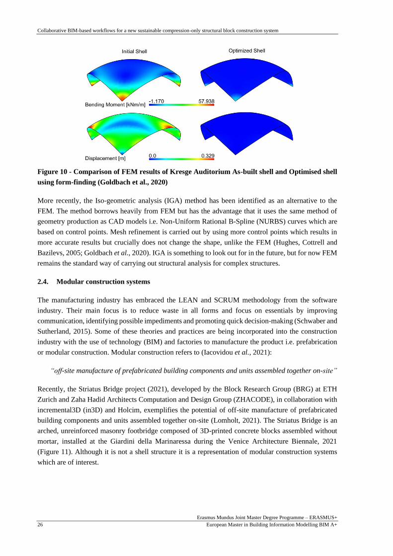
results such as bending moments, stresses and displacements can be obtained. As can be seen in Figure
9 and Figure 10, a slight change in shape from shape optimisation or form-finding processes can lead to
more favourable FEM results than a shape from other design processes. In the constructed shell, which
is a segment of a sphere, edge beams and complex connections were required to transfer the excessive
forces at the corners, but these could have been avoided by using shell optimisation as shown in the
diagrams on the right of Figure 10.
Figure 9 – The Kresge Auditorium, Cambridge, 1955, by Eero Saarinen, as of 2003, with detail
of support (Adriaenssens et al., 2014)
1. Define the problem
2. Create a clean model
3. Define the Loads and constraints
4. Mesh the model (discretise)
5. Define the analysis method
6. Process (solve)
7. Post process
Collaborative BIM-based workflows for a new sustainable compression-only structural block construction system
Erasmus Mundus Joint Master Degree Programme – ERASMUS+
European Master in Building Information Modelling BIM A+ 26
Figure 10 - Comparison of FEM results of Kresge Auditorium As-built shell and Optimised shell
using form-finding (Goldbach et al., 2020)
More recently, the Iso-geometric analysis (IGA) method has been identified as an alternative to the
FEM. The method borrows heavily from FEM but has the advantage that it uses the same method of
geometry production as CAD models i.e. Non-Uniform Rational B-Spline (NURBS) curves which are
based on control points. Mesh refinement is carried out by using more control points which results in
more accurate results but crucially does not change the shape, unlike the FEM (Hughes, Cottrell and
Bazilevs, 2005; Goldbach et al., 2020). IGA is something to look out for in the future, but for now FEM
remains the standard way of carrying out structural analysis for complex structures.
2.4. Modular construction systems
The manufacturing industry has embraced the LEAN and SCRUM methodology from the software
industry. Their main focus is to reduce waste in all forms and focus on essentials by improving
communication, identifying possible impediments and promoting quick decision-making (Schwaber and
Sutherland, 2015). Some of these theories and practices are being incorporated into the construction
industry with the use of technology (BIM) and factories to manufacture the product i.e. prefabrication
or modular construction. Modular construction refers to (Iacovidou et al., 2021):
“off-site manufacture of prefabricated building components and units assembled together on-site”
Recently, the Striatus Bridge project (2021), developed by the Block Research Group (BRG) at ETH
Zurich and Zaha Hadid Architects Computation and Design Group (ZHACODE), in collaboration with
incremental3D (in3D) and Holcim, exemplifies the potential of off-site manufacture of prefabricated
building components and units assembled together on-site (Lomholt, 2021). The Striatus Bridge is an
arched, unreinforced masonry footbridge composed of 3D-printed concrete blocks assembled without
mortar, installed at the Giardini della Marinaressa during the Venice Architecture Biennale, 2021
(Figure 11). Although it is not a shell structure it is a representation of modular construction systems
which are of interest.

Collaborative BIM-based workflows for a new sustainable compression-only structural block construction system
Erasmus Mundus Joint Master Degree Programme – ERASMUS+
European Master in Building Information Modelling BIM A+ 27
Figure 11 – The Striatus Bridge being built through the assembly of modules (Lomholt, 2021)
On-site construction has been the modus operandi in the construction industry for centuries. However,
off-site or prefabrication systems are becoming more prevalent. For example, the permanent
prefabrication market share in North America increased by 50% in the years between 2015 and 2018
(Ribeirinho et al., 2020); currently, up to 80% of Scandinavian new houses manufactured off-site; and
in the UK, 15000 modular houses are constructed each year (Iacovidou et al., 2021). This is due to the
many advantages of prefabrication including (Bertram et al., 2019):
a) Acceleration of project timelines by up to 50%
b) Increased profits of up to 20%
c) Significant construction cost savings
d) Less waste and more sustainable designs
Another advantage is better quality control on the product by shifting the focus to an integrated design
approach involving multiple stakeholders. This reduces the possibility of making costly mistakes i.e.
when design decisions are made upfront, they are less costly than if made later on during the project
such as during construction. There is also increased safety since the product can be manufactured in a
controlled environment. Additionally, construction is quicker since the products can be delivered to site
in the order in which they are required and quickly assembled. Furthermore, if it is a dry connection,
there is no need to wait for the concrete to achieve enough strength before installing the next elements.
And finally, automation of production can occur using machines in the factory (Lopez and Froese, 2016;
Bertram et al., 2019).
Despite this, modular construction has its own problems and challenges especially those related to
transportation and others such as (Polat, 2008; Iacovidou et al., 2021):
a) High costs to transport components to site
b) Local restrictions on truck weights
c) Restricted vehicular load access on certain roads
d) Restrictions on the size of the parts that can be carried at any one time
e) Job loss for on-site trades such as masons, bricklayers, plasterers
Besides, it has recently been reported that two modular constructed large buildings in the United
Kingdom (UK) caught fire and were destroyed. It is suspected that this was due to unseen cavities in the
structure that allowed the fire to spread easily and that were brought about by the modular construction

Collaborative BIM-based workflows for a new sustainable compression-only structural block construction system
Erasmus Mundus Joint Master Degree Programme – ERASMUS+
European Master in Building Information Modelling BIM A+ 28
(Stout, 2021). This suggests that connections between the prefabricated components in modular
construction are of significant importance and will be discussed further in this thesis.
Still, Iacovidou et al., (2021) argue that making use of digital technologies in modular construction will
affect sustainability, productivity, and resource efficiency in the whole construction value chain.
Essentially, digitalisation in that area will have and should have domino effect into other areas of the
construction industry, encouraging an integrated approach and making disasters like the recent fires in
the UK, unlikely. It is perhaps for this reason that Modular Integrated Construction (MIC) is “the future
of buildings” with various construction stakeholders involved from early in the design stage and the use
of digital technologies (Abdelmageed and Zayed, 2020).
2.5. Design and construction of shell structures
2.5.1. Computational design and parametric modelling for shell structures
Due to the complexities of shell structures, it is time consuming to conduct the structural analysis and
design calculations by hand. For this reason, computational design and parametric modelling have been
co-opted into the design process to take advantage of the computer’s abilities and to be able to make
changes easily. In his doctorate thesis, Davis (2013) discusses how there is contention about what
parametric modelling is and how various authors have asserted that all design is parametric. But Davis
(2013) argues against this and insists on the uniqueness and richness of parametric design as opposed to
just stemming from the mathematical sense of the word “parametric” and being synonymous with
change.
Parametric modelling is the use of the relationships between different parts of the model i.e. parameters
to enable quick changes during the modelling process or (Stasiuk, 2018):
“a set of equations that express information regarding the deployment of an architectural
information system, as explicit functions of a number of parameters”
The beauty of parametric modelling is that it requires the designer to fully understand the design and
how it works. This will reduce the likelihood or necessity of changes later on during the project when it
will prove most costly, as mentioned before (Davis, 2013).
Computational design makes use of parametric models to perform (Stasiuk, 2018):
“explicit transformative operations on parameters through the use of algorithms in pursuit of a
design outcome”
Both parametric modelling and computational design are particularly useful for the design of shell
structures using the form-finding method. Many parameters can be adjusted, and computational power
can be used to come up with an infinite number of possible solutions and then further optimisation can
be carried out to obtain the best solution through what is called generative modelling (Stasiuk, 2018).
These methods normally require a level of programming knowledge to take full advantage of their
capabilities and lessen the repetitive tasks involved once parameters are changed. Programming can be
done either textually using an extensive list of languages (refer to Stasiuk (2018)) such as Python or

Collaborative BIM-based workflows for a new sustainable compression-only structural block construction system
Erasmus Mundus Joint Master Degree Programme – ERASMUS+
European Master in Building Information Modelling BIM A+ 29
C++. Alternatively, for non-IT experts in the AEC industry, visual programming for example using
Autodesk Dynamo or Grasshopper 3D is available but these may be expensive and more limited in
capacity.
To overcome these costs, Vizotto (2010), used mathematical programming to come up with his own
computational model to produce free-form optimised geometries inspired by Heinz Isler and perform
structural calculations using the membrane theory of shell structures and the finite element method. The
method starts with a simulated horizontal, plane surface, flexible membrane of any shape. Boundary
constraints, self-weight and forces are then applied. This leads to iterations to obtain the optimal
deformed shape of the structure by considering the structural equations and the FEM method in Section
2.3.3 and strain energy. This method is similar to the Dynamic Relaxation Method mentioned in Section
2.3.2. Under gravitational loading, the resulting shape is a tension structure which is inverted to produce
compression-only vaults from defined envelopes as shown in Figure 12.
Figure 12 - Initial plan views and final 3D shape from form-finding computation (Vizotto, 2010)
As can be seen, depending on the initial shape and the position of the supports, different shapes can be
generated. Still, despite the savings cost, the proposed method is complex to implement and using
proprietary software would be easier. The method’s results are comparable with other software results
and physical methods so, can be used as a check to ensure a model is working as desired (Vizotto, 2010).
In contrast, around the same time, other authors also came up with their own methods for form-finding
(Tomás and Martí, 2010). In the study, they set up a system of objective functions and make use of the
strain energy (SE), weight and tensile stress on the faces of the shell to obtain optimal mechanical
functioning based on a set of geometric variables for the defined parametric model. This is comparable
to the Vizotto (2010) model except that the equations are solved in the optimisation module of ANSYS
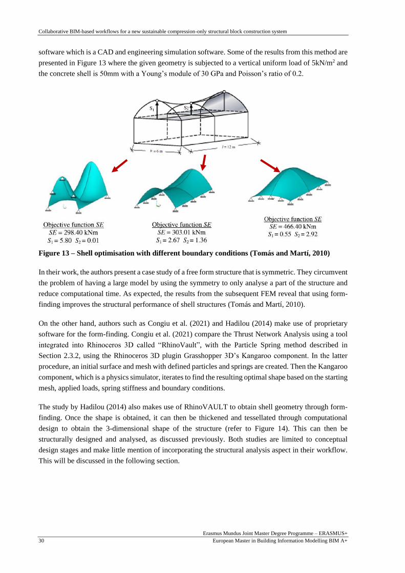
Collaborative BIM-based workflows for a new sustainable compression-only structural block construction system
Erasmus Mundus Joint Master Degree Programme – ERASMUS+
European Master in Building Information Modelling BIM A+ 30
software which is a CAD and engineering simulation software. Some of the results from this method are
presented in Figure 13 where the given geometry is subjected to a vertical uniform load of 5kN/m2 and
the concrete shell is 50mm with a Young’s module of 30 GPa and Poisson’s ratio of 0.2.
Figure 13 – Shell optimisation with different boundary conditions (Tomás and Martí, 2010)
In their work, the authors present a case study of a free form structure that is symmetric. They circumvent
the problem of having a large model by using the symmetry to only analyse a part of the structure and
reduce computational time. As expected, the results from the subsequent FEM reveal that using form-
finding improves the structural performance of shell structures (Tomás and Martí, 2010).
On the other hand, authors such as Congiu et al. (2021) and Hadilou (2014) make use of proprietary
software for the form-finding. Congiu et al. (2021) compare the Thrust Network Analysis using a tool
integrated into Rhinoceros 3D called “RhinoVault”, with the Particle Spring method described in
Section 2.3.2, using the Rhinoceros 3D plugin Grasshopper 3D’s Kangaroo component. In the latter
procedure, an initial surface and mesh with defined particles and springs are created. Then the Kangaroo
component, which is a physics simulator, iterates to find the resulting optimal shape based on the starting
mesh, applied loads, spring stiffness and boundary conditions.
The study by Hadilou (2014) also makes use of RhinoVAULT to obtain shell geometry through form-
finding. Once the shape is obtained, it can then be thickened and tessellated through computational
design to obtain the 3-dimensional shape of the structure (refer to Figure 14). This can then be
structurally designed and analysed, as discussed previously. Both studies are limited to conceptual
design stages and make little mention of incorporating the structural analysis aspect in their workflow.
This will be discussed in the following section.

Collaborative BIM-based workflows for a new sustainable compression-only structural block construction system
Erasmus Mundus Joint Master Degree Programme – ERASMUS+
European Master in Building Information Modelling BIM A+ 31
Figure 14 - Result of form-finding using RhinoVAULT & Panelisation of shell (Hadilou, 2014)
2.5.2. Prefabricated sequential construction
In recent years, many prefabricated sequential construction methods have been proposed. As an
example, Bao & Li (2020) propose the use of LEGO-inspired sustainable structures that can be
assembled or disassembled as per the structural requirements and most importantly, in a sequential way.
The authors are advocating for precast and using the LEGO method to i) make the connection between
elements quicker with dry joints, and ii) reuse structures by disassembling the elements and assembling
them elsewhere (refer to Figure 15).
Figure 15 - Illustration of LEGO-inspired blocks and assembled structure (Bao & Li, 2020)
In contrast to wet joints, the use of dry joints means there is no need to wait for concrete to dry on site.
What is more, the method makes the blocks re-usable and therefore more sustainable and cost effective.
In this case they use what they call “bendable concrete” which resists tension rather than rebar for
improved durability and increased structural efficiency. They also use post tensioned (PT) cables to
reduce cracking and bolts for the connections (Bao and Li, 2020).
The system seems to have some restrictions and flaws such as the cost of production of the concrete,
applicability only to certain structures that have an overall rectilinear shape and the need for complex

Collaborative BIM-based workflows for a new sustainable compression-only structural block construction system
Erasmus Mundus Joint Master Degree Programme – ERASMUS+
European Master in Building Information Modelling BIM A+ 32
algorithms to establish the correct assembly and disassembly procedure. The need for having customised
moulds for each block also significantly increases the time required to produce the blocks. But the
authors argue that the production time can be reduced in future with the use of 3D printing (Bao and Li,
2020).
Companies like Lock Block Ltd and Shay Murtagh Ltd are at the forefront of the precast construction
industry in Canada and Ireland & UK respectively. Lock Block Ltd is committed to sustainability and
claim to use “100% recycled aggregates and sand”. They use block units with connection keys at the
interface to ensure robustness which can be further strengthened by connecting them with rods. The
panels apply to various structural types, such as retaining walls, tunnels, overpasses etc. They are also
easily assembled and disassembled; are reusable and have the advantage that no expensive scaffolding
is required for construction (Lock Block, 2021). Regardless, their panels and construction systems are
limited to specific structural types and would not be suitable for the free-form structural types being
discussed in this thesis.
Figure 16 - Lock Block Products (Lock Block, 2021)
In comparison, Shay Murtagh Ltd has a wider applicability than the Lock Block system. They focus on
larger elements consisting of precast beams, box culverts, precast tanks, or bespoke precast concrete and
buildings by defining the individual precast panels that will form the building. Moreover, they consider
a holistic view and design optimisation, addressing some of the challenges mentioned in Section 2.4
such as space on site, cost, constructability, sustainability. For instance, they plan and optimise the
sequence of construction based on panel manufacture time at the factory, transportation to site, space on
site and installation time (Gomes, 2021; Shay Murtagh, 2021). However, the construction system
sometimes involves grouting or wet connection and propping of panels that requires waiting for
hardening before constructing the next levels.
Figure 17 - Large precast concrete panels on a truck (Shay Murtagh, 2021)
Collaborative BIM-based workflows for a new sustainable compression-only structural block construction system
Erasmus Mundus Joint Master Degree Programme – ERASMUS+
European Master in Building Information Modelling BIM A+ 33
2.6. Collaborative BIM based workflows
A collaborative BIM based workflow uses an integrated approach whereby multiple stakeholders in the
AEC industry collaborate with digital tools and processes to design and construct a structure. This is
particularly useful for complex shell structures as explained in this literature review.
2.6.1. Digitalisation
Digitalisation is the integration of digital technologies in processes that were previously analogue media-
based processes. It is imperative for the AEC industry to embrace digitalisation to be more productive
and increase innovation. It can be achieved with the use of BIM which will encourage collaboration and
integration of multidisciplinary teams (World Economic Forum, 2018).
For example, construction drawings in the past were drawn by hand and physically handed to the
contractor to conduct the construction. Nowadays, the situation is completely different with the use of
either Computer-Aided Design (CAD) or Building Information Modelling (BIM) processes to perform
the same task, thereby optimising and making the process quicker and more efficient and minimising
mistakes. In the same way, engineers used to design on paper. While this is still the case sometimes,
often, the design is conducted on a computer using computer programs that automate and quicken the
design process. Similarly, the prefabrication can be automated, as is done in the automotive industry,
rather than done manually (Bertram et al., 2019).
During construction, automation can also be achieved using technologies such as 3D printing. This will
become important particularly in the construction industry is afflicted by labour shortages (Turner &
Townsend, 2018) a gap which can be covered by digital manufacturing processes. Digitalisation is
relevant because it also allows the concept of “building it twice” which reduces the possibility that
mistakes are made that will affect the construction process. Chuck Eastman in his prescient work
(Eastman, 1974) describes a Building Description System (BDS) which is a large digital database of
objects and their properties and their relationships with each other representing objects in a real building.
The BDS has the following properties (Eastman, 1974):
• Change of item properties in one part of the drawing leads to automatic updates in all the other
elevations, plans etc. ensuring efficiency and reducing redundancy found in paper drawings
• Object-oriented (borrowed from programming with properties such as inheritance and
abstraction) database rather than line-based with construction item libraries to choose from
• Embedded metadata about the object provided by the manufactures for design, construction and
facility management purposes
• Numerical analysis of the building’s properties
• No obsolete information, information is always available and current
• Automation of quantity take-offs, building code checks and clash detection
This is the basis for what is called BIM today. For instance, 3-dimensional models can be set up with
object libraries available in proprietary modelling platforms like Autodesk Revit as well as online with
manufacturers details. It is possible to include geometrical and metadata of objects and functionalities
that dwarf the capabilities of CAD. The 3D model can have BIM uses such as MEP modelling, Structural

Collaborative BIM-based workflows for a new sustainable compression-only structural block construction system
Erasmus Mundus Joint Master Degree Programme – ERASMUS+
European Master in Building Information Modelling BIM A+ 34
modelling, and analysis as well as Energy analysis and Facility Management. The goal of BIM is to
bridge the islands or silos of automation of AEC disciplines and enable accurate and consistent
communication and flow of information through all the phases of a project using a digital 3-dimensional
model (World Economic Forum, 2018).
2.6.2. Computational Design, Formwork development and physical prototyping
Kontovourkis et al., (2019) propose a computational design and optimisation framework linked to a
customisable modular formwork and automated fabrication of shell structures. The goal is to minimise
material waste, consequently reducing cost and the environmental impact of construction. The
construction automation also leads to decreased material and energy consumption, as well as increased
construction quality and accuracy. Their BIM-based workflow involving architects, engineers and
contractors is presented in the form of the framework shown in Figure 18.
Figure 18 – Overall framework and details of computational design optimisation steps
(Kontovourkis et al., 2019)
In their framework, the first part is the computational design optimization where the architect performs
the form-finding of the structure. Secondly, the linear static structural analysis is conducted by the
structural engineer in tandem with the topology optimisation and the parametric design by the architect.
Third, once the geometry is finalised, the detailed design is carried out.
Figure 19 - 3D printed shell prototype with hexagonal tessellation (Adriaenssens et al., 2014)

Collaborative BIM-based workflows for a new sustainable compression-only structural block construction system
Erasmus Mundus Joint Master Degree Programme – ERASMUS+
European Master in Building Information Modelling BIM A+ 35
This part also includes the tessellation process where the structure is subdivided into segments like the
partitions of the shell of a tortoise. Though in this case the designer can select the type of shape of the
units e.g. rectangular, hexagonal, isosceles triangles, etc. as seen in Figure 14 and Figure 19
(Kontovourkis, Phocas and Katsambas, 2019).
In the study, the surface obtained from form-finding is tessellated into square cells that are then offset
to form a 3D structure. Through topological optimisation, the square cell becomes a Y-shaped unit which
is defined as reinforced concrete for the structural analysis. The next part is the development of the semi-
automatic formwork mechanism that can adjust its shape according to the tessellated unit. Nonetheless,
the mechanism that was developed for the formwork is limited to the Y-shaped concrete components in
their study and is not configurable for other tessellated shapes (Kontovourkis, Phocas and Katsambas,
2019).
A more sophisticated method presented by Borg Costanzi et al. (2018) uses 3D printing and allows the
production of structures of any shape by casting its constituent concrete panels onto a flexible and
adaptable mould rather than a flat plane – refer to Figure 20.
Figure 20 - Schematic of adaptable mould (Borg Costanzi et al., 2018)
The authors also make use of Grasshopper 3D to create the geometry and a custom workflow from
design to production and assembly to create the structure. However, in the study the authors neglect to
address the complexity of the required construction supports for shell or free-form structures. They also
neither discuss the structural robustness of the solution nor the type of connection between the panels in
detail (Borg Costanzi et al., 2018).
The last part of the work by Kontovourkis et al. (2019) is the physical prototyping where each unit of
the structure is brought to life through adjusting the shape of the formwork, casting the concrete then
removing the unit from the mould, before assembling the units to form the structure. The authors
envision that the units will be precast. Once on site, sequential construction of the units will occur with
bracing and supports to hold the structure in place until is completed (Kontovourkis, Phocas and
Katsambas, 2019).
The main advantage of the proposed workflow is the form-finding and topology optimisation which
ensures material optimisation. Another advantage is the semi-automated nature of the formwork for the
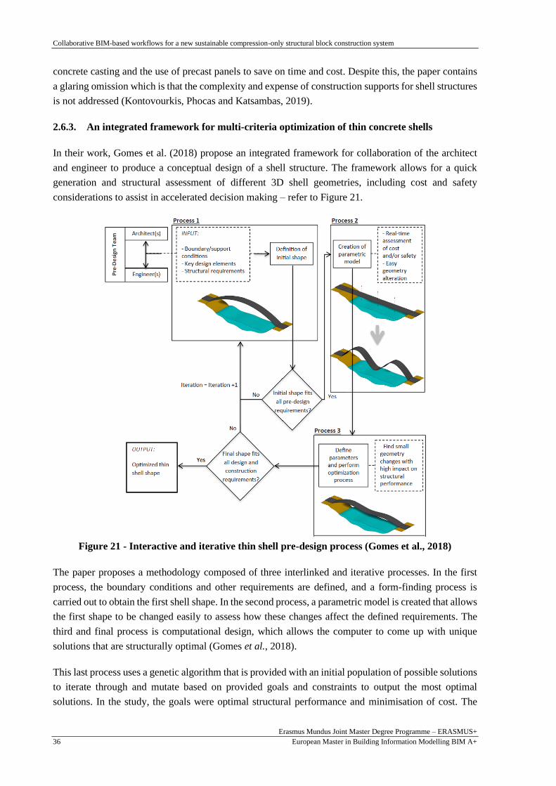
Collaborative BIM-based workflows for a new sustainable compression-only structural block construction system
Erasmus Mundus Joint Master Degree Programme – ERASMUS+
European Master in Building Information Modelling BIM A+ 36
concrete casting and the use of precast panels to save on time and cost. Despite this, the paper contains
a glaring omission which is that the complexity and expense of construction supports for shell structures
is not addressed (Kontovourkis, Phocas and Katsambas, 2019).
2.6.3. An integrated framework for multi-criteria optimization of thin concrete shells
In their work, Gomes et al. (2018) propose an integrated framework for collaboration of the architect
and engineer to produce a conceptual design of a shell structure. The framework allows for a quick
generation and structural assessment of different 3D shell geometries, including cost and safety
considerations to assist in accelerated decision making – refer to Figure 21.
Figure 21 - Interactive and iterative thin shell pre-design process (Gomes et al., 2018)
The paper proposes a methodology composed of three interlinked and iterative processes. In the first
process, the boundary conditions and other requirements are defined, and a form-finding process is
carried out to obtain the first shell shape. In the second process, a parametric model is created that allows
the first shape to be changed easily to assess how these changes affect the defined requirements. The
third and final process is computational design, which allows the computer to come up with unique
solutions that are structurally optimal (Gomes et al., 2018).
This last process uses a genetic algorithm that is provided with an initial population of possible solutions
to iterate through and mutate based on provided goals and constraints to output the most optimal
solutions. In the study, the goals were optimal structural performance and minimisation of cost. The
Collaborative BIM-based workflows for a new sustainable compression-only structural block construction system
Erasmus Mundus Joint Master Degree Programme – ERASMUS+
European Master in Building Information Modelling BIM A+ 37
final part of this process is selection of a final structural shape based on a structural analysis that meets
all design requirements (Gomes et al., 2018).
The study shows that custom tools are sometimes necessary to perform certain tasks that go beyond the
capabilities of proprietary software. This can be achieved by accessing the proprietary software’s API
and/or using programming languages such as C# and Python. In the study, a component was created in
C# that can obtain geometry information from the modelling software and transfer it to the structural
analysis FEM software automatically setting up and running the analysis then reverting the results back
to the modelling software for optimisation. This interoperability is a key feature in a BIM workflow to
prevent information loss and latency as well as quicken decision making (Gomes et al., 2018).
The proposed framework emphasises the importance of communication between the architect and
engineer throughout the process, to ensure that any potential problems are highlighted and dealt with
timeously. The automation resolves some of the most tedious and repetitive tasks that are invariably a
part of the design process so that architects and engineers can focus on conceptual design, engineering
thinking and analyses of results. Nonetheless, the study is limited to the conceptual design stage only
and it remains to be seen whether or how it would work in practise with other considerations such as
formwork for construction of the shell structure (Gomes et al., 2018).

Collaborative BIM-based workflows for a new sustainable compression-only structural block construction system
Erasmus Mundus Joint Master Degree Programme – ERASMUS+
European Master in Building Information Modelling BIM A+ 38
This page is intentionally left blank

Collaborative BIM-based workflows for a new sustainable compression-only structural block construction system
Erasmus Mundus Joint Master Degree Programme – ERASMUS+
European Master in Building Information Modelling BIM A+ 39
3. PARAMETRIC MODELLING AND COMPUTATIONAL
DESIGN TOWARDS MODEL GENERATION
3.1. Introduction
Based on the Perpectum research proposal by Azenha (2019), this work proposes compression-only
structures tessellated into precast panels cast on a flexible mould, with in-situ self-sensing prestressing
cables. The panel size can be approximately 1m x 1m with 200mm to enable easy lifting without
complex machinery required. A thickness of 300mm is selected preliminarily to assess structural
performance. As seen in the literature review presented in Chapter 2, the technological aspect and
modular fabrication could be available with the current technology (refer to Figure 20).
Ideally, the prestressing cables employed in Perpectum, are low stress, non-metallic and cost-effective
members made up of multiple layered and braided cables similar to those used in the marine industry.
However, in this thesis, 20mm diameter steel cables are used to evaluate the validity of the proposed
system. The construction system proposes sequential assembly of the concrete panels to maintain
robustness during construction, similar to masonry construction (refer to Figure 11). Each concrete panel
is prestressed in two directions as it is added to the structure to maintain stability. The idea is to have
technology that allows the concrete panels to have external anchor heads for the post tensioning that are
decoupled after stressing to allow the next concrete panel to be placed.
In the age of BIM, the integration of parametric modelling and computational design processes is
becoming a fundamental part of the design process and so it is with the proposed construction system.
Thus, the objectives of this section are to explain the use of parametric modelling and computational
design processes to create the structural shape, thicken and tessellate the structure and add the cable
geometry; assign an assembly sequence to each panel using cellular automata and generate the BIM
model. A regular, simple geometry is used for the description of the processes to simplify and focus on
the explanation of the procedures. However, it is possible to define more complex geometries provided
they have width of at least 4m, at least four sides and either line or point supports. The structure’s height
depends on functional and architectural requirements.
The chapter starts with an explanation of the vault design system (Section 3.2) followed by a general
overview of the design procedure (Section 3.3). This is followed by Section 3.4 that explicitly describes
the step by step implementation of the algorithm for the design, including the procedure for obtaining
the construction sequence using cellular automata principles. The chapter ends with a description of the
connection from the model generation software to the BIM platform (Section 3.5).
3.2. Geometrical concept for vault system
A compression-only structural shape with supports on the ground or on walls can be achieved using
parametric modelling and computation design from a form-finding process. Starting with an arbitrary
planar geometry, it is possible to use point or line supports to constrain the shape - refer to Figure 22.

Collaborative BIM-based workflows for a new sustainable compression-only structural block construction system
Erasmus Mundus Joint Master Degree Programme – ERASMUS+
European Master in Building Information Modelling BIM A+ 40
Figure 22 - Parameters and constraints for form-finding for a generic rectangular shape - Top
view
Then, an upward load can be applied to the points restrained by lines with an assigned stiffness (springs),
and through iterations to obtain static equilibrium and a compression-only structure.
Using the generic rectangular shape shown in Figure 22, the main concepts, parameters, and constraints
essential for the form-finding process are explained as follows:
1) The length, a and width, b can be increased or decreased. In fact, the curves representing these
lengths can be linear or curved.
2) The size of x and y can be changed by changing the number of divisions in any one of the
directions, as required.
3) Consequently, this leads to changes in the lengths of the springs and positions of the nodes.
4) Any of the points can be selected as supports; any of the lines can be selected as support lines.
The supports do not change position whilst all other points can shift once the load is applied.
5) The loads are applied on the points.
6) The lines are assigned a spring stiffness that can be adjusted as required.
Therefore, depending on the boundary conditions, an infinite number of structural forms is possible. As
described in Chapter 2, the resulting structure can be divided into panels which can be post tensioned
during construction to reduce the formwork required. The resulting structure from form-finding is more
efficient in terms of the force distribution in the system.
3.3. Overview of parametric modelling and computational design workflow
This section describes the parametric modelling and computational design workflow. The form-finding
and construction sequencing procedures of the project were carried out through the Visual Programming
Language (VPL) Grasshopper 3D that is executed within the Rhinoceros 3D version 7 (Rhino)
Computer-Aided Design (CAD) software.
Parameters a - Width
b - Length
x - Dimension
y - Dimension
Point
Line
b
a
x x x x
y
y
y

Collaborative BIM-based workflows for a new sustainable compression-only structural block construction system
Erasmus Mundus Joint Master Degree Programme – ERASMUS+
European Master in Building Information Modelling BIM A+ 41
There were three main reasons for this choice i) it has built-in add-ons to develop the form-finding
processes such as Kangaroo and because ii) it allows the implementation of interoperability operations
with a BIM platform (Revit or ArchiCAD). Various other approaches for form-finding can be used
including DynaShape, an add-on of Dynamo – a VPL of Autodesk Revit or textual programming such
as Python. However, the former was found to not be as robust as Kangaroo and it would have been more
time-consuming to troubleshoot as there is currently less literature on it. Then the latter required more
time for familiarisation but in theory would have interesting possibilities especially with the use of
pyRevit, a Python based plug-in for Revit.
After the first stage of design generation in Rhino, a plug-in called “Rhino.Inside.Revit” was used for
bi-directional interoperability between Rhino 7 and Autodesk Revit 2021, allowing users to model in
the Rhino environment and have the full geometrical shape immediately available in Autodesk Revit for
BIM purposes. Any changes in Rhino were instantaneously updated to Autodesk Revit, similar to how
Dynamo works.
3.4. Implementation of the computational design model
This section describes the process by which the computational design model was defined and generated
and connected to the BIM platform. The description includes the form-finding process using Kangaroo;
followed by the conversion of the Kangaroo output from planar to solid and its subsequent tessellation
to represent the panels; thereafter the procedure for cable curves generation is explained and followed
by the cellular automata algorithm to define the assembly sequence; finally the connection procedure to
the BIM platform is presented.
3.4.1. Structural equilibrium by form-finding
To generate geometries with compression-only structural behaviour, a form-finding algorithm was
defined in Grasshopper 3D. The initial step in the implementation of the algorithm was using Kangaroo
and its Dynamic Relaxation form-finding strategy, described in Chapter 2. Although Kangaroo was used
in the study, it is possible to use other Grasshopper 3D plug-ins such as Karamba 3D or BullAnt created
by Geometry Gym. However, the two are geared towards conducting the structural analysis in
Grasshopper 3D which was not the intention in this case. In summary, the procedure is as follows: points
are defined for a surface, from which a mesh or grid of points connected by lines are defined; then the
lines are assigned a stiffness and loads are applied to each node on the grid; supports on the grid are
defined and finally iterations occur to find static equilibrium.
Since the form-finding is achieved by the application of forces to a network of points connected by
springs, the first stage consists in the definition of a network. Figure 23 illustrates the generative schema
of a simple network of 7m by 5m with 1m subdivisions in each direction. The sizes of the divisions of
the network were chosen to keep the resulting panels the same size as much as possible and in
consideration of the space for the post tensioned cables. However, the size changes to 200mm more
than 1m after the form-finding is carried out. The process begins with the definition of the points (Figure
23a) which are then used to form the lines (Figure 23b) which are in turn used to define the surface
(Figure 23c).

Collaborative BIM-based workflows for a new sustainable compression-only structural block construction system
Erasmus Mundus Joint Master Degree Programme – ERASMUS+
European Master in Building Information Modelling BIM A+ 42
a) Points b) Lines c) Surface
d) Support points (0, 1, 2, 3) e) Force application positions f) Spring positions
Figure 23 - Generative Schema of a regular 7x5 network, top view and axonometric view
Depending on the desired shape, some of the “naked” points (points on the boundary of the mesh) were
selected to be the support points (Figure 23d). In this case, the four corner points, 0 to 4 are the support
points. These are the points that will remain in the same position when the form-finding is carried out.
The “clothed” points (points inside the boundary of the mesh) connecting the lines of the mesh were
assigned a vertical upward force (refer to Figure 23e) to move the points, find equilibrium and generate
a shape. Thereafter, all the vertical and horizontal lines between the points of the mesh were assigned a
spring stiffness that provides resistance to movement when the vertical force is applied (refer to Figure
23f).
Figure 24 - Grasshopper definition for the generation of a simple relaxed mesh through
Kangaroo form-finding solver
5m 7
m

Collaborative BIM-based workflows for a new sustainable compression-only structural block construction system
Erasmus Mundus Joint Master Degree Programme – ERASMUS+
European Master in Building Information Modelling BIM A+ 43
Subsequently, as shown in Figure 24, under the INPUTS, the geometry (mesh), Force Objects (forces
and springs), AnchorPoints (supports) and number of iterations were used as inputs to the Physics
SOLVER “ZombieKangaroo” to perform the form-finding. The regular Kangaroo solver was not used
to avoid having to reset and having the solver always running in the background, thereby using up
memory, and taking up time. A fixed number of iterations was selected for the solver to come up with
equilibrium based on the input parameters. When the solver is run, the OUTPUT from the solver (see
Figure 24) is a 3-dimensional parabolic-shaped, dome-shaped or vault-shaped mesh. Varying the
starting points, support locations, spring stiffness and vertical force results in different shapes as shown
in Figure 25.
a) 4 corner support points b) Line supports at three edges c) Line supports at long edges
Figure 25 – Form-finding mesh results with 3 varying inputs, axonometric view
Initially, the use of genetic algorithms was considered in finding the optimal size of the panels or the U
and V divisions. However, it was found that this was unnecessary as the solution was just a matter of a
simple calculation for the simpler geometries in this work. But this would be useful for optimisation of
the system in future.
3.4.2. Thickening, tessellating and discretisation of the structure
The next process was the creation of individual solid panels by thickening and tessellating the mesh
output (see Figure 19). Grasshopper 3D has panelling tools options that could have been used to
accomplish this task. Alternatively, Revit Adaptive Components were considered but the resulting
individual panels were perpendicular to the surface. This resulted in angled separation at the interface
and the intended smooth geometry is not maintained (see Figure 26). Although methods to overcome
this are proposed in the literature (Hadilou, 2014) another procedure thought to be simpler was followed.
Figure 26 – 3D view of gaps between panels resulting non-smooth curve from using Panelling tools
Gap between panels

Collaborative BIM-based workflows for a new sustainable compression-only structural block construction system
Erasmus Mundus Joint Master Degree Programme – ERASMUS+
European Master in Building Information Modelling BIM A+ 44
The vault model illustrated in Figure 25c was considered as a case study for this chapter. As the first
step, the mesh geometry is converted to a solid object. This was done by choosing a thickness (300mm
in this case), and the vertices of the mesh were shifted up and down to form the top and bottom surface
of the structure respectively. The U and V curves are used to split the surface into panels by obtaining
the middle U/V line of the entire surface and dividing it into the desired number of panels and then using
these curves to split/fragment the surface as shown in Figure 27.
a) Bottom surface b) Bottom surface fragmented c) Top surface fragmented
Figure 27 - Generative schema: Surface fragmentation, axonometric view
a) Bottom surface U/V Curves b) Top surface U/V Curves c) Top and bottom U/V Curve surfaces
Figure 28 - Generative Schema: U/V Curves for Top and Bottom Surface, axonometric view
Figure 29 – 3D structure segmented into panels and plan view with labelling

Collaborative BIM-based workflows for a new sustainable compression-only structural block construction system
Erasmus Mundus Joint Master Degree Programme – ERASMUS+
European Master in Building Information Modelling BIM A+ 45
A final operation was conducted combining Figure 27b and c with Figure 28c to obtain the 3D structure
segmented into panels as shown in Figure 29.
3.4.3. Generation of cable curves
Once the panels had been generated, the next procedure was defining the algorithm for generation of the
cable curves in Grasshopper 3D. In the algorithm, cable curves representing the centre line of the post
tensioned cables were defined for the transfer to the structural analysis software which requires curves
to form the cables. Referring to a single panel as shown in Figure 30, the cable edge distances c and e
are between a third and a quarter of the panel dimension l or m. As mentioned, the panel dimension l or
m is at approximately 1m and the panel thickness is fixed at 300mm. The cable centre line is offset down
from the panel centre by its radius for the cables in one direction and offset up by the same dimension
in the other direction so that the cables do not clash.
Figure 30 - Panel and cable parameters and constraints
Using the same example as for the panels, the process for the generation of the cable curves was as
follows. First, two separate surfaces were offset to the desired positions for the centre line of the cables
in the U and V direction. Next, the central V line was selected and split into 3 times the number of
specified V divisions.
a) Division of surface at centre b) U curves on edges and in panels c) Selection of U curves in panels
Figure 31 - Creation and selection of cable curves in U direction, axonometric view
Parameters
l – panel length
m – panel width
c, e – edge distance
d, f – cable distance
- cable
- anchor head
c c d e
e
f
l
m
thickness
Central V curve

Collaborative BIM-based workflows for a new sustainable compression-only structural block construction system
Erasmus Mundus Joint Master Degree Programme – ERASMUS+
European Master in Building Information Modelling BIM A+ 46
Thereafter, curves in the U direction were defined from these points to the edge of the surface (see
Figure 31b). Following which, a pattern was used to separate the U curves on the edges of the panel
from those which were within the panels as shown resulting in Figure 31c. After this procedure, an
intersection component was executed using the edges/curves of the panels to obtain the cable curves per
panel only in the U direction. The same procedure was repeated on the lower surface to get the cable
curves in the other direction with U and V direction/curves swapped with results shown in Figure 32.
a) Division of surface at centre b) V curves on edges and in panels c) Selection of V curves in panels
Figure 32 - Creation and selection of cable curves in V direction, axonometric view
a) b)
Figure 33 – Top and Bottom cable curves in U direction and labelling for each panel
a) b)
Figure 34 – Left and Right cable curves in V direction and labelling for each panel
Central U curve

Collaborative BIM-based workflows for a new sustainable compression-only structural block construction system
Erasmus Mundus Joint Master Degree Programme – ERASMUS+
European Master in Building Information Modelling BIM A+ 47
The cable curves were further divided into four lists to separate the top and bottom (Figure 33) and, left
and right cable curves (Figure 34) in each panel. The reason for this was to have labelling consistent
with the labelling of the panels (see Figure 29). Figure 33 and Figure 34 depict the Top view of the
example for easier visualisation. The panel in the left bottom corner is numbered “0” (see Figure 29)
while the cables in the “0” panel will also be numbered “0” (refer to Figure 33 and Figure 34).
3.4.4. Creating the assembly sequence using a cellular automata algorithm
The panels and cables presented in the previous sections were assigned an assembly sequence.
Controlling the assembly sequence of the panels means they can be brought onto site in the order in
which they are needed thereby saving time and money. Additionally, it also allows designers to generate
multiple solutions and consequently optimize the forces on the structure during construction. The
assembly sequence algorithm in this study was defined using principles from cellular automata
algorithms. The method was selected for automating the assembly sequence because it was successfully
used previously for a similar application on dam construction sequences (Fernandes, 2015) and for its
use of decision-making based on previous information. Generally, cellular automata algorithms make
use of a network of cells and their neighbours to change the status of the cell i.e. dead or alive,
alternatively active or inactive, depending on simple rules based on how many of its neighbours have
the same status (Herr and Kvan, 2007). In this case, the cells were related to the panels and the status
refers to whether the panel has been placed on the structure during construction.
The cellular automata algorithm was defined in Grasshopper 3D and run using the Anemone Plug-in
which allows users to run loops. The Loop Start component has some input data which is then connected
to and updated with data from the Loop End component. The user can specify the number of repetitions
then use the reset button to run the loops. Once completed, the user can obtain the final data from the
Loop End component as explained in Table 1 and illustrated in Figure 35.
Table 1 – Grasshopper Cellular automata algorithm task description
Task Description
1. Inputs The initial layout is defined and each cell is entered initially as “dead”. The number
of iterations is set and the reset button is used to start the loop.
2. Loop Start Received inputs and exchanges information with the Loop End.
3. Find Neighbours Proximity component is used to find the number of neighbours based on the initial
layout.
4. No. of live neighbours Used to calculate how many neighbours that each cell has.
5. Separate dead/live cells Sift component is used to separate the dead and live cells in each loop.
6. Dead cell test Checks whether a particular cell is dead depending on how many live neighbouring
cells it has.
7. Live cell test Checks whether a particular cell is alive depending on how many live neighbouring
cells it has and whether it was alive before.
8. Combine next gen. dead
and live cells
Combines information from Task 6 and 7 and inputs back into the system.
9. Merge old and new
information
Records information during each loop and enters that information back into the new
loop.
10. Loop End Data can be obtained after the number of iterations specified have been run

Collaborative BIM-based workflows for a new sustainable compression-only structural block construction system
Erasmus Mundus Joint Master Degree Programme – ERASMUS+
European Master in Building Information Modelling BIM A+ 48
Fig
ure
35 –
Gra
ssh
op
per
cel
lula
r au
tom
ata
alg
ori
thm
usi
ng
th
e A
nem
on
e P
lug-i
n
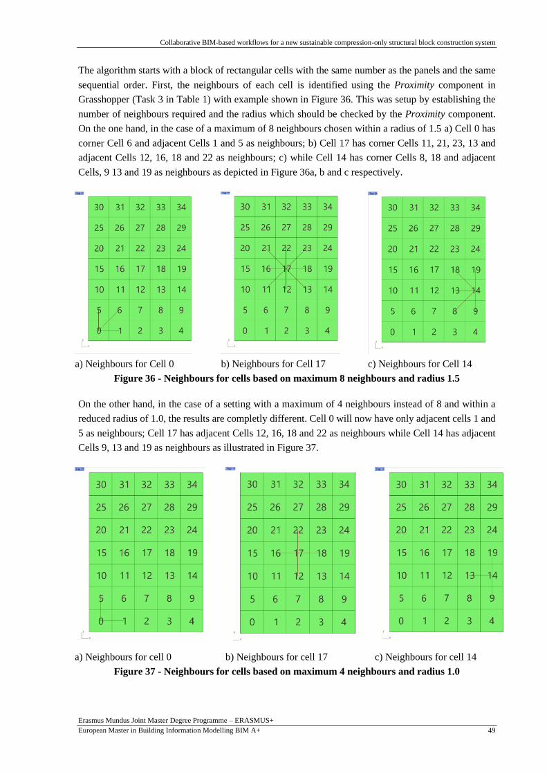
Collaborative BIM-based workflows for a new sustainable compression-only structural block construction system
Erasmus Mundus Joint Master Degree Programme – ERASMUS+
European Master in Building Information Modelling BIM A+ 49
The algorithm starts with a block of rectangular cells with the same number as the panels and the same
sequential order. First, the neighbours of each cell is identified using the Proximity component in
Grasshopper (Task 3 in Table 1) with example shown in Figure 36. This was setup by establishing the
number of neighbours required and the radius which should be checked by the Proximity component.
On the one hand, in the case of a maximum of 8 neighbours chosen within a radius of 1.5 a) Cell 0 has
corner Cell 6 and adjacent Cells 1 and 5 as neighbours; b) Cell 17 has corner Cells 11, 21, 23, 13 and
adjacent Cells 12, 16, 18 and 22 as neighbours; c) while Cell 14 has corner Cells 8, 18 and adjacent
Cells, 9 13 and 19 as neighbours as depicted in Figure 36a, b and c respectively.
a) Neighbours for Cell 0 b) Neighbours for Cell 17 c) Neighbours for Cell 14
Figure 36 - Neighbours for cells based on maximum 8 neighbours and radius 1.5
On the other hand, in the case of a setting with a maximum of 4 neighbours instead of 8 and within a
reduced radius of 1.0, the results are completly different. Cell 0 will now have only adjacent cells 1 and
5 as neighbours; Cell 17 has adjacent Cells 12, 16, 18 and 22 as neighbours while Cell 14 has adjacent
Cells 9, 13 and 19 as neighbours as illustrated in Figure 37.
a) Neighbours for cell 0 b) Neighbours for cell 17 c) Neighbours for cell 14
Figure 37 - Neighbours for cells based on maximum 4 neighbours and radius 1.0

Collaborative BIM-based workflows for a new sustainable compression-only structural block construction system
Erasmus Mundus Joint Master Degree Programme – ERASMUS+
European Master in Building Information Modelling BIM A+ 50
A lower number of neighbours was used for the purposes of this study to reduce and control the number
of cells activated in each loop. The assembly sequence in this case requires connection with adjacent
panels only and not corner cells for connection with the PT cables see Figure 5.
The cellular automata algorithm was caried out by first setting all the cells as “dead” by assigning them
a value of zero. Then for the following generation, selected cells were set as “alive” by assigning them
a value of one. For subsequent generations, the algorithm checked the current status i.e. dead or alive
(zero or one), of each cell for that generation and then decided whether to change its status or keep it the
same. This was done by first establishing a particular cell’s neighbours (see Figure 37) and then checking
the value of each neighbour (zero or one).
Then the sum of the values of all neighbouring cells determined whether the cell in question would live
(be assigned a value of one) or stay dead (value zero) in the subsequent generation. Dead cells only
became alive once they were in the proximity of between one and three live cells. Once activated, live
cells stayed alive for all subsequent generations. The activated (live) cells during each loop/run were
recorded to form the assembly sequence.
Changing the assembly sequence leads to changes in the forces on the structure during construction. The
sequence of activation and hence the assembly sequence can be changed by adjusting which cells are
activated or set alive first. For instance, starting with all dead (green) cells (see Generation 0 in Figure
38a) then activating (red) the innermost bottom and top cells at either end i.e. Cells 1, 2 and 3; 31, 32
and 34, results in generation 2, 3 and 4 shown in Figure 38b, c and d, respectively:
a) b)
c) d)
Figure 38 - Cell automata activation sequence – inner panels activated first

Collaborative BIM-based workflows for a new sustainable compression-only structural block construction system
Erasmus Mundus Joint Master Degree Programme – ERASMUS+
European Master in Building Information Modelling BIM A+ 51
This assembly sequence was then applied to the order of the panels and cables as seen in Figure 39.
a) b)
Figure 39 - 3D and Plan View labelled with Assembly Sequence (1)
Alternatively, starting with all dead cells (Figure 40a) then activating the outermost live cells at the four
corners i.e. Cells 0, 5, 4 and 9; 30, 25, 29 and 34, results in the sequence shown in Figure 40b), c) and
d) as follows.
a) b)
c) d)
Figure 40 - Cell automata activation sequence – outer panels activated first
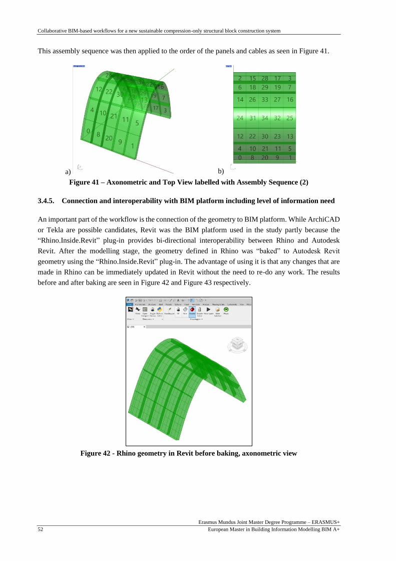
Collaborative BIM-based workflows for a new sustainable compression-only structural block construction system
Erasmus Mundus Joint Master Degree Programme – ERASMUS+
European Master in Building Information Modelling BIM A+ 52
This assembly sequence was then applied to the order of the panels and cables as seen in Figure 41.
a) b)
Figure 41 – Axonometric and Top View labelled with Assembly Sequence (2)
3.4.5. Connection and interoperability with BIM platform including level of information need
An important part of the workflow is the connection of the geometry to BIM platform. While ArchiCAD
or Tekla are possible candidates, Revit was the BIM platform used in the study partly because the
“Rhino.Inside.Revit” plug-in provides bi-directional interoperability between Rhino and Autodesk
Revit. After the modelling stage, the geometry defined in Rhino was “baked” to Autodesk Revit
geometry using the “Rhino.Inside.Revit” plug-in. The advantage of using it is that any changes that are
made in Rhino can be immediately updated in Revit without the need to re-do any work. The results
before and after baking are seen in Figure 42 and Figure 43 respectively.
Figure 42 - Rhino geometry in Revit before baking, axonometric view

Collaborative BIM-based workflows for a new sustainable compression-only structural block construction system
Erasmus Mundus Joint Master Degree Programme – ERASMUS+
European Master in Building Information Modelling BIM A+ 53
a) Shaded graphic display with single panel
displaced and highlighted
b) Wireframe graphic display to show cables
Figure 43 - Revit geometry low level of detail, axonometric view
Depending on the project phase and level of information need required, the geometry can be updated,
and more information added to the model accordingly for the purposes of BIM. The cable curves would
be sufficient for a lower level of detail but for a higher one, openings and the thickened cables would
have to be represented. The operation can be carried out in Grasshopper and transmitted to Revit via the
same procedure described earlier in this section. For the example presented in this section, the results
are depicted in Figure 44.
a) Consistent Colors Visual Style with single panel
displaced
b) Wireframe Visual Style showing cable thickness
Figure 44 - Revit geometry with higher level of detail, axonometric view

Collaborative BIM-based workflows for a new sustainable compression-only structural block construction system
Erasmus Mundus Joint Master Degree Programme – ERASMUS+
European Master in Building Information Modelling BIM A+ 54
Metadata can also be added either using the Grasshopper interface Rhino.Inside.Revit plug-in or using
the Revit interface to assign native Revit families, set materials etc.
Other tools such as Geometry Gym’s Rhino-Revit IFC and Hummingbird can be used for converting
Rhino geometry to Revit geometry. However, Hummingbird is only compatible with specific versions
of Rhino and Revit and is not currently supported by the latest version of these programs. Similarly,
Geometry Gym’s IFC conversion procedure from Rhino to Revit requires a license and does not provide
direct bidirectionality like the Rhino.Inside.Revit plug-in which accesses the Revit API. Nevertheless,
Grevit, a free Grasshopper 3D Plug-in is just as effective as the Rhino.Inside.Revit plug-in and also
allows a workflow suitable for BIM but the component exchanges are limited to certain Revit family
types such as beams, columns and slabs.
3.5. 3D printing
The proposed construction system was assessed by 3D printing the blocks from the form-finding process
described in this chapter (refer to Figure 45). Each block consisted of 4 openings, two in each direction,
slightly offset from the centre to prevent them from clashing. A keystone was placed on the topmost
blocks to accommodate the assembly sequence which started from the supports on either side of the
structure to the keystone. The blocks were connected by elastic wire passing through the openings in
place of the PT cables. Tensioning the blocks using the wires adjusts the structural shape into position
as shown in Figure 46 and Figure 47
Figure 45 - 3D printed blocks before assembly
Figure 46 - 3D printed blocks after assembly - Front view

Collaborative BIM-based workflows for a new sustainable compression-only structural block construction system
Erasmus Mundus Joint Master Degree Programme – ERASMUS+
European Master in Building Information Modelling BIM A+ 55
Figure 47 - 3D printed blocks after assembly – axonometric view

Collaborative BIM-based workflows for a new sustainable compression-only structural block construction system
Erasmus Mundus Joint Master Degree Programme – ERASMUS+
European Master in Building Information Modelling BIM A+ 56
This page is intentionally left blank

Collaborative BIM-based workflows for a new sustainable compression-only structural block construction system
Erasmus Mundus Joint Master Degree Programme – ERASMUS+
European Master in Building Information Modelling BIM A+ 57
4. STRUCTURAL ANALYSIS PROCEDURES
4.1. Introduction
BIM Model Uses such as structural analysis are usually conducted following the model generation
process as described in Chapter 3. Structural design analysis using FEA is vital to determine the
construction and performance viability of shell structures. Moreover, decisions on the building blocks
of the design including the material types, material strengths and connection types are made at this stage.
This information is then communicated to the relevant parties involved in the construction process.
The FEA described in Section 2.3.3 was carried out using DIANA FEA version 10.4 (herein after
referred to as DIANA), a Finite Element Analysis software developed by TNO Building and
Construction Research Institute in Delft, The Netherlands. Other software such as Autodesk Robot
Structural Analysis have the advantage of having direct interoperability with Autodesk Revit. Moreover,
other FEA software such as SAP2000, ABAQUS and ANSYS are often used in structural engineering.
Nevertheless, DIANA FEA was selected for this study because of its: i) ability to perform phased
analysis which is essential for the thesis; ii) incorporation of Python scripts allowing automation of what
would otherwise be tedious and time consuming tasks if done manually; iii) license availability and
abundance of tutorials for learning.
As described in Chapter 3, once the geometry is in the BIM platform Autodesk Revit 2021 (herein after
referred to as Revit), a plug-in developed in C# programming language is used to automatically generate
a Python script that converts the Revit geometry syntax into DIANA geometry syntax. This Python
script is then run in DIANA to reproduce the model from Revit. The procedure described was followed
because there is currently no direct interoperability between DIANA and architectural programs such as
Revit/Rhino.
An additional Python script was implemented to automatically assign the material properties, support
conditions and loading on the structure as well as set-up the phased analysis in DIANA. Finally, the
structural analysis is carried out in DIANA to ensure the structural soundness of the final solution which
will be discussed in Chapter 5.
This Chapter presents the structural analysis methodology. Section 4.2 presents the structural concept
of the proposed construction system. Section 4.3 describes the interoperability tool defined to connect
Revit to DIANA. Section 4.4 discusses the DIANA property assignment and phased analysis
procedures. DIANA examples are presented in Section 4.5 and the interoperability tool employed to
automate the phased analysis is described in Section 4.6.
4.2. Structural concept of the construction system
4.2.1. Panel size and material
The panel size can be approximately 1m x 1m with 200mm to enable easy lifting without complex
machinery required and a thickness of 300mm is selected, as mentioned in Chapter 3. The stresses are
expected to be low and therefore low-strength concrete can be used to reduce the environmental impact

Collaborative BIM-based workflows for a new sustainable compression-only structural block construction system
Erasmus Mundus Joint Master Degree Programme – ERASMUS+
European Master in Building Information Modelling BIM A+ 58
of this construction system. This might be achieved by investigating using concrete mixes with recycled
materials. In this study, the C30/37 concrete grade is used as a first check for tensile strength. However,
creep, shrinkage and thermal effects will not be considered and are beyond the scope of the thesis.
4.2.2. Post tensioning load
To estimate the load requirements at the interface, preliminary hand calculations were performed
assuming a cantilever system with two tilted panels: one on top of the other with a PT load of 25kN.
The expected stress at the interface between the panels is estimated with this PT load. In estimating the
interface stresses between the top and bottom block, the first step consisted of drawing a free body
diagram where a 3D global coordinate system (X,Y,Z) and a 2D local coordinate system (u,v) are used
– refer to Figure 48.
Figure 48 – PT Block Free body diagram and stress interface calculations
The free body diagram of the top panel consists of the PT loading and the panel self-weight denoted as
Pv and Wz respectively. The PT loads act along the v-axis parallel to the block, while the self-weight
acts parallel to the Z-axis. In theory, the self-weight component along the v-axis (Wv) contributes to the
perpendicular stress on the interface, while the component on the u-axis (Wu) would generate a bending
moment at the interface between the two panels (Figure 48).
By introducing a PT loading of 25kN in each cable, compressive (negative) stress of 0.357 MPa and
zero (positive) tension stress occur. Values less than 25kN would lead to the occurrence of tensile
stresses at the interface. This would mean that the two panels are not in complete contact with each
other. Therefore, a conservative PT Load of 40kN is used. This value is lower than the usual forces for
commercial PT systems. Cable diameter of 20mm will be used which is close to the standard 18.7mm
used for PT systems.
b
d
u
v
h
L
Pv
Pv
Wz
60 deg.

Collaborative BIM-based workflows for a new sustainable compression-only structural block construction system
Erasmus Mundus Joint Master Degree Programme – ERASMUS+
European Master in Building Information Modelling BIM A+ 59
4.2.3. Temporary supports during construction
Ideally, the system would have no construction supports. However, preliminary studies suggested that
tension stresses may arise if no provisional supports are provided. Therefore, a decision was made to
add provisional supports e.g. made by a prop connected to a standard plate, which can be quickly sized
and removed as required, with minimal increase, if any, to the construction cost.
4.3. Interoperability tool for connection between modelling platform and structural analysis
software
Currently, few platforms allow direct interoperability between architectural and structural analysis
software. Hence the most common modus operandi of structural analysis software is accessing the
geometry using Industry Foundation Class (IFC), an object-oriented data exchange standard. Although,
DIANA, has the capability of reading IFC syntax, ad-hoc programming was implemented to have more
flexibility in customising the data exchange.
Solid geometry in both Revit and DIANA are made up of surfaces (faces) which are defined by a set of
edges and vertices. Since the geometry from Revit obtained in Chapter 3 is made up of panels (solids),
it is necessary to translate this information to DIANA geometry. This is done by customising a C# script
designed by fellow Masters student (Correia, 2021) whose thesis will be submitted in September, 2021.
The script accesses the Revit Application Programming Interface (API) and converts the Revit
nomenclature to DIANA nomenclature. Then the script produces a Python script with syntax readable
in the DIANA environment. The algorithm consists of the following steps i) identifying the panel and
cable geometry from Revit ii) decomposing the Revit geometry into basic elements iii) composing the
basic elements into DIANA geometry syntax iv) producing a Python script
In Revit syntax, the cable geometry is a curve and encompasses non-linear type lines. This is useful for
this project where free form structures are generated. The Revit curves are tessellated and divided into
segments. Then, the points forming these segments are combined to form DIANA curves (Correia, 2021)
as illustrated in Figure 49.
Figure 49 - Summary of conversion process of cable curves from Revit to DIANA geometry
Similarly, the C# code uses the Revit API to obtain the panel geometry. More specifically, the algorithm
first decomposes each panel which in Revit semantics are called “solids” into “faces” as illustrated in
Figure 50. Afterwards, faces are decomposed into edges that are tessellated into points. The points from
Revit by default are defined using the Imperial System (dimensions in inches) and therefore are
converted to the Metric System (dimensions in meters) which is the default system in DIANA.
Thereafter, these points are converted to DIANA curves which in turn are converted to wires. The wires
Revit Curves Revit Points DIANA Curves/Wires

Collaborative BIM-based workflows for a new sustainable compression-only structural block construction system
Erasmus Mundus Joint Master Degree Programme – ERASMUS+
European Master in Building Information Modelling BIM A+ 60
are then sewn together to form sheets. Finally, the sheets are combined to form a DIANA block that
represents a panel.
Figure 50 - Summary of the conversion process of a single panel from Revit to DIANA geometry
4.4. DIANA FEA Property assignment and Phased Analysis procedures
4.4.1. Property assignment procedure
The first step in creating a new Project in DIANA is to define shapes that can be related to real world
construction items. The detailed steps for the procedure are presented in Appendix 2. In this case, the
shapes were created as described in Chapter 3 and read into DIANA using the interoperability tool
presented in Section 4.3. Thereafter, the following DIANA steps, which will be discussed further, can
be followed:
i) Add materials and assign material characteristics
ii) Assign shapes to geometry. Shapes can be assigned as either geometry or reinforcement
iii) Assign a material to the shapes
iv) Add loads to the shapes
When adding a new material to the project, DIANA allows the user to select whether it will be modelled
as a Class and based on the Class chosen, the Material model can be chosen which means the results
will be based on established international codes for instance the fib Model Code for Concrete Structures
2010 or Eurocode 2 EN 1992-1-2 for reinforcement.
For Concrete materials, the Class options are the “Concrete design codes” and “Concrete and masonry”.
The “Concrete and masonry” was selected for this study so that the results are applicable to different
codes. The material model selected was “Linear elastic isotropic” because the concrete would have the
Revit Solid/faces Revit Edges Revit Points
DIANA Block DIANA Sheets DIANA Curves/Wires

Collaborative BIM-based workflows for a new sustainable compression-only structural block construction system
Erasmus Mundus Joint Master Degree Programme – ERASMUS+
European Master in Building Information Modelling BIM A+ 61
same properties throughout and have linear elastic behaviour i.e. stress and strain are linear, and Hooke’s
law applies. Additionally, the materials are expected to recover after the application of loads to the
structure.
Conversely, for the post tensioning cable reinforcing, “Reinforcements” or “Steel design codes” can be
selected. Ideally, the goal would be to have post tensioning cables made from maritime cables but for
the purposes of checking the viability of the construction system, steel properties were used. Once again,
no code was selected and the more generic “Linear elasticity” behaviour was selected. However, the
“Bonding” aspect was included to have the option to specify that the post tensioning cable is not bonded
to the concrete. This means that the post tensioning cables and concrete can move independently of one
another.
After the Material Class and Material model have been selected, the next step is to specify the aspects
to be included. Aspects such as Creep, Shrinkage, Thermal effects, and Strength reduction can be
included in the analysis. However, as mentioned before, none of this behaviour was modelled since the
focus here is the framework, but these can be easily set up in DIANA. Thereafter, the Young’s Modulus,
Poisson’s ratio and Mass density can be specified.
Once the materials have been defined, the “Element Class” type is selected to define the shape.
“Structural solids” were selected as the Element class for the panels in the study. Structural solids are
general purpose, allowing arbitrary loading and three-dimensional stress. The alternative would be
“Rubber solids” used for rubber-like structures with hyper elasticity which is not applicable here.
DIANA’s default elements from structural solids are of type HX24L with 8 nodes and a 2x2x2
integration scheme. Further research would be required to investigate how a different element would
affect the results.
The post tensioning cables in the DIANA model can be represented by assigning a load to the curves.
The process requires firstly adding a new load case and then adding loads to the load case. Then, the
“Load type” is selected as a “Post tensioning load”. This load type can only be assigned to reinforcement
therefore the curves representing the cables are set as “Reinforcement shapes” before being loaded with
the Post tensioning load. Either end of the curve or both ends can be assigned as the “Anchor point”
where the force is applied. In this case only one of the ends was selected as the anchor point to make it
easier to automate the process. Finally, the “Nodal anchor force” in kN, “Coulomb friction coefficient”
and “Wobble factor” values need to be specified in case of prestress losses.
4.4.2. DIANA Phased Analysis
The DIANA FEA program offers various analysis types, from Structural Linear Static to Structural
Nonlinear and Structural Response Spectrum. The “Staged construction” analysis was selected for the
purposes of this study to investigate how the structure responds to the gradual addition of precast
structural panels and their post tensioning cables during construction. Each construction stage is added
manually to the analysis as shown in Appendix 2. The number of stages equates to the number of blocks
in the structure. Each stage is accumulative and equates to the previous block plus activation of a new
block and its post tensioning cables. It is also worth noting that the post tensioning stress from the
previous blocks are not destressed and then stressed again with a longer cable joining the old and new

Collaborative BIM-based workflows for a new sustainable compression-only structural block construction system
Erasmus Mundus Joint Master Degree Programme – ERASMUS+
European Master in Building Information Modelling BIM A+ 62
cables. This was considered early on in the study but found to be overly complicated to enact in the
model and in a real construction. However, it is worth looking into in the future should the technology
be available.
4.5. DIANA Examples
4.5.1. Four-block model phased analysis
There are several steps that have to be repeated for each analysis stage. For example, DIANA staged
analysis is usually used for geo-mechanical structures. Therefore, it is necessary to specify that there is
no water present and de-select both the “Clear displacements at beginning of stage” and “Initialize
stresses in new elements” options for each stage of the analysis (refer to Figure 52b). Additionally, for
the loads, the self-weight is automatically included in each analysis stage. However, the post tensioning
load must be added to each analysis stage.
To get familiar with the phased analysis in DIANA an example consisting of four panels with size 1m
x 1m x 0.3m, angled at 60 degrees from the horizontal plane is hereafter presented. The step by step
procedure for creating the geometry and setting up the analysis stages is presented in Appendix 2. The
model is composed of four concrete panels each with four PT cables as shown in Figure 51.
Figure 51 – DIANA example with four panels - Isometric and right view
The PT cables ensure the connection and stability of the panels during construction. Each PT cable is
related to the block it is in. For instance, all the cables in Block 4 are in a group called Cables 4 (Cable
4A, 4B, 4C and 4D as denoted in Figure 51). The construction consists of four stages, each one a single
analysis stage in DIANA. The active parts for each of the four stages are shown as axonometric views
and inputs in Figure 52 and Figure 53.
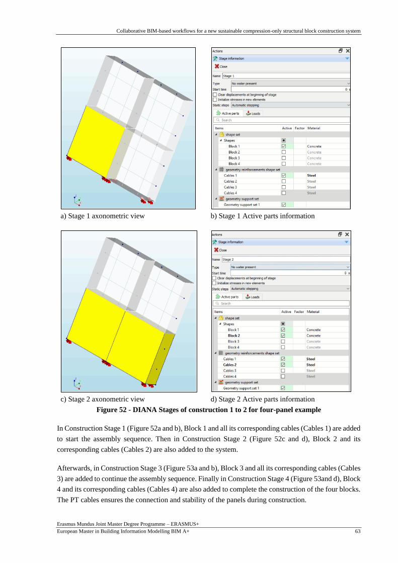
Collaborative BIM-based workflows for a new sustainable compression-only structural block construction system
Erasmus Mundus Joint Master Degree Programme – ERASMUS+
European Master in Building Information Modelling BIM A+ 63
a) Stage 1 axonometric view b) Stage 1 Active parts information
c) Stage 2 axonometric view d) Stage 2 Active parts information
Figure 52 - DIANA Stages of construction 1 to 2 for four-panel example
In Construction Stage 1 (Figure 52a and b), Block 1 and all its corresponding cables (Cables 1) are added
to start the assembly sequence. Then in Construction Stage 2 (Figure 52c and d), Block 2 and its
corresponding cables (Cables 2) are also added to the system.
Afterwards, in Construction Stage 3 (Figure 53a and b), Block 3 and all its corresponding cables (Cables
3) are added to continue the assembly sequence. Finally in Construction Stage 4 (Figure 53and d), Block
4 and its corresponding cables (Cables 4) are also added to complete the construction of the four blocks.
The PT cables ensures the connection and stability of the panels during construction.

Collaborative BIM-based workflows for a new sustainable compression-only structural block construction system
Erasmus Mundus Joint Master Degree Programme – ERASMUS+
European Master in Building Information Modelling BIM A+ 64
a) Stage 3 axonometric view b) Stage 3 Active parts information
c) Stage 4 axonometric view d) Stage 4 Active parts information
Figure 53 - DIANA Stages of construction 3 to 4 for four-block example
As illustrated the process of manually adding a construction stage and activating each the blocks and
cables is a laborious process. For this reason, an interoperability tool was designed to automatically
perform the phased analysis with the assembly sequence related to the cellular automata algorithm.
4.5.2. Python scripting for DIANA
The DIANA FEA User’s manual provides specific Python commands that are readable and executable
by the DIANA API and can be used to automate certain tasks. Alternatively, the command console
inside DIANA displays the Python commands for each action carried out in DIANA. For example, a
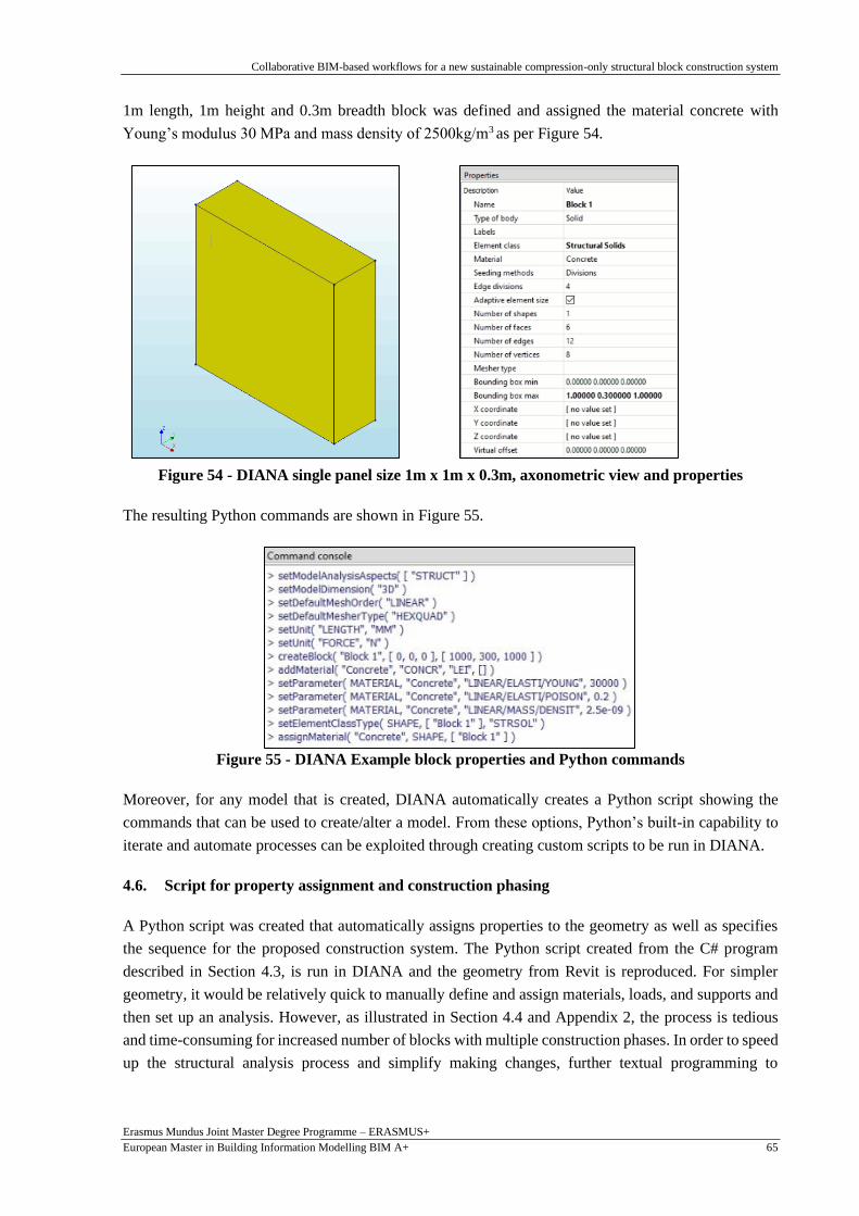
Collaborative BIM-based workflows for a new sustainable compression-only structural block construction system
Erasmus Mundus Joint Master Degree Programme – ERASMUS+
European Master in Building Information Modelling BIM A+ 65
1m length, 1m height and 0.3m breadth block was defined and assigned the material concrete with
Young’s modulus 30 MPa and mass density of 2500kg/m3 as per Figure 54.
Figure 54 - DIANA single panel size 1m x 1m x 0.3m, axonometric view and properties
The resulting Python commands are shown in Figure 55.
Figure 55 - DIANA Example block properties and Python commands
Moreover, for any model that is created, DIANA automatically creates a Python script showing the
commands that can be used to create/alter a model. From these options, Python’s built-in capability to
iterate and automate processes can be exploited through creating custom scripts to be run in DIANA.
4.6. Script for property assignment and construction phasing
A Python script was created that automatically assigns properties to the geometry as well as specifies
the sequence for the proposed construction system. The Python script created from the C# program
described in Section 4.3, is run in DIANA and the geometry from Revit is reproduced. For simpler
geometry, it would be relatively quick to manually define and assign materials, loads, and supports and
then set up an analysis. However, as illustrated in Section 4.4 and Appendix 2, the process is tedious
and time-consuming for increased number of blocks with multiple construction phases. In order to speed
up the structural analysis process and simplify making changes, further textual programming to

Collaborative BIM-based workflows for a new sustainable compression-only structural block construction system
Erasmus Mundus Joint Master Degree Programme – ERASMUS+
European Master in Building Information Modelling BIM A+ 66
automate some of the pre-processing including defining the material, supports and loading properties
and assigning them to the curves and blocks is carried out as part of this work (refer to Figure 56).
For instance, a script was created where the material “Concrete” is defined and assigned properties such
as the compressive strength and then assigned to each block. Similarly, the material “Steel” is defined
and assigned properties such as the Young’s Modulus of Elasticity and then assigned to each cable. The
post tensioning load and the anchor positions is also assigned for each cable. By using textual
programming, these values can easily be adjusted if required without too much difficulty. This is
particularly useful in an AEC design environment where changes are bound to occur.
Figure 56 – Part of Python script setting up properties
The last part of the Python script involves relating the cables to the blocks such that the cables would be
activated when the corresponding block is activated in the assembly sequence. Because of the way the
assembly sequence was set up in the Chapter 3, the numbering is in the order required and the desired
cable can easily be recalled as needed. This is done using iterations and the “for” loop. A single analysis
is defined consisting only of the first block in the assembly sequence and its cables. The following
analysis duplicates the previous analysis with the difference that the next block in the specified sequence
(see Section 3.4.4) is activated and so on until the last block and its cables have been added. The full
Python script is available in Appendix 1.
#Set units setUnit( "LENGTH", "MM" ) setUnit( "FORCE", "N" ) #Create materials addMaterial( "Concrete", "CONCR", "LEI", [] ) setParameter( "MATERIAL", "Concrete", "LINEAR/ELASTI/YOUNG", 30000 ) setParameter( "MATERIAL", "Concrete", "LINEAR/MASS/DENSIT", 2.5e-09 ) setParameter( "MATERIAL", "Concrete", "LINEAR/ELASTI/POISON", 0.2 ) addMaterial( "Steel", "REINFO", "LINEAR", [ "FRLGTH", "NOBOND" ] ) setParameter( "MATERIAL", "Steel", "LINEAR/ELASTI/YOUNG", 200000 ) setParameter( "MATERIAL", "Steel", "FREELE/FRLGTH", 1 ) #add Selfweight addSet( "GEOMETRYLOADSET", "Dead load" ) createModelLoad( "Global Load 1", "Dead load" ) #add PT loads addSet( "GEOMETRYLOADSET", "PT load" ) createBodyLoad( "PT load", "PT load" ) setParameter( "GEOMETRYLOAD", "PT load", "LODTYP", "POSTEN" ) setParameter( "GEOMETRYLOAD", "PT load", "POSTEN/TENTYP", "ONEEND" ) setParameter( "GEOMETRYLOAD", "PT load", "POSTEN/ONEEND/FORCE1", 40000 ) setParameter( "GEOMETRYLOAD", "PT load", "POSTEN/SHEAR", 0 )
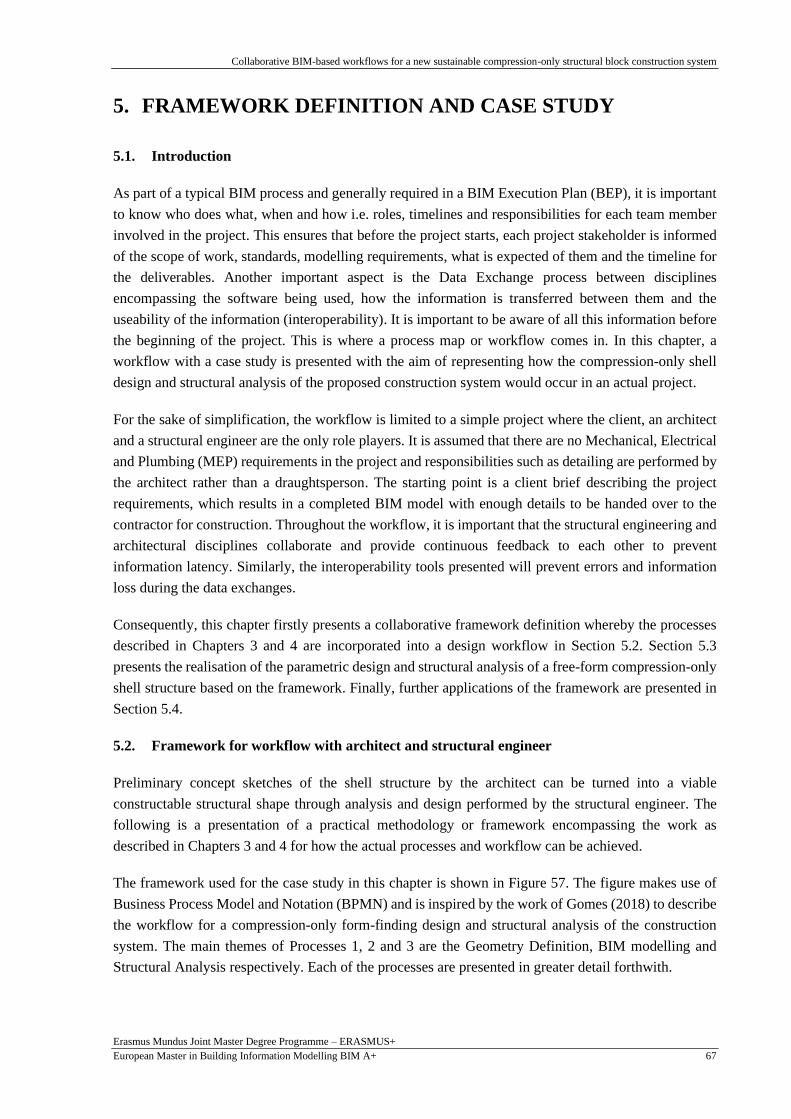
Collaborative BIM-based workflows for a new sustainable compression-only structural block construction system
Erasmus Mundus Joint Master Degree Programme – ERASMUS+
European Master in Building Information Modelling BIM A+ 67
5. FRAMEWORK DEFINITION AND CASE STUDY
5.1. Introduction
As part of a typical BIM process and generally required in a BIM Execution Plan (BEP), it is important
to know who does what, when and how i.e. roles, timelines and responsibilities for each team member
involved in the project. This ensures that before the project starts, each project stakeholder is informed
of the scope of work, standards, modelling requirements, what is expected of them and the timeline for
the deliverables. Another important aspect is the Data Exchange process between disciplines
encompassing the software being used, how the information is transferred between them and the
useability of the information (interoperability). It is important to be aware of all this information before
the beginning of the project. This is where a process map or workflow comes in. In this chapter, a
workflow with a case study is presented with the aim of representing how the compression-only shell
design and structural analysis of the proposed construction system would occur in an actual project.
For the sake of simplification, the workflow is limited to a simple project where the client, an architect
and a structural engineer are the only role players. It is assumed that there are no Mechanical, Electrical
and Plumbing (MEP) requirements in the project and responsibilities such as detailing are performed by
the architect rather than a draughtsperson. The starting point is a client brief describing the project
requirements, which results in a completed BIM model with enough details to be handed over to the
contractor for construction. Throughout the workflow, it is important that the structural engineering and
architectural disciplines collaborate and provide continuous feedback to each other to prevent
information latency. Similarly, the interoperability tools presented will prevent errors and information
loss during the data exchanges.
Consequently, this chapter firstly presents a collaborative framework definition whereby the processes
described in Chapters 3 and 4 are incorporated into a design workflow in Section 5.2. Section 5.3
presents the realisation of the parametric design and structural analysis of a free-form compression-only
shell structure based on the framework. Finally, further applications of the framework are presented in
Section 5.4.
5.2. Framework for workflow with architect and structural engineer
Preliminary concept sketches of the shell structure by the architect can be turned into a viable
constructable structural shape through analysis and design performed by the structural engineer. The
following is a presentation of a practical methodology or framework encompassing the work as
described in Chapters 3 and 4 for how the actual processes and workflow can be achieved.
The framework used for the case study in this chapter is shown in Figure 57. The figure makes use of
Business Process Model and Notation (BPMN) and is inspired by the work of Gomes (2018) to describe
the workflow for a compression-only form-finding design and structural analysis of the construction
system. The main themes of Processes 1, 2 and 3 are the Geometry Definition, BIM modelling and
Structural Analysis respectively. Each of the processes are presented in greater detail forthwith.

Collaborative BIM-based workflows for a new sustainable compression-only structural block construction system
Erasmus Mundus Joint Master Degree Programme – ERASMUS+
European Master in Building Information Modelling BIM A+ 68
Fig
ure
57
– F
ram
ework
for
case
stu
dy w
ork
flow

Collaborative BIM-based workflows for a new sustainable compression-only structural block construction system
Erasmus Mundus Joint Master Degree Programme – ERASMUS+
European Master in Building Information Modelling BIM A+ 69
A zoom in of the first process i.e. Geometry Definition is shown in Figure 58. This is the most important
process as its implementation affects the downstream processes.
Figure 58 - Process 1: Geometry definition
Initially, it requires the architect to obtain a brief from the client and produce the project scope (Process
1a) and preliminary concept sketch (Process 1b). Process 1b specifies Revit as the software of choice
but since the sketch is only for discussion purposes, any suitable software can be used. This information
is shared with the engineer (Process 1c) who then defines the preliminary parametric model by using
Grasshopper 3D and performs form-finding in Kangaroo (Process 1d). Process 1 concludes with an
agreed upon structural shape in Rhino and Revit (Process 1h) which relies on the collaborative effort
from both the structural engineer and the architect (Process 1e-g). Due to the Rhino.Inside.Revit plug
in, the Rhino geometric shape is then immediately available in Revit (Process 1h).

Collaborative BIM-based workflows for a new sustainable compression-only structural block construction system
Erasmus Mundus Joint Master Degree Programme – ERASMUS+
European Master in Building Information Modelling BIM A+ 70
A zoomed in version of the BIM process is depicted in Figure 59. This process serves as the starting
point for the construction model which is finalised in the third process.
Figure 59 - Process 2: BIM
The process involves the development of the Revit model by the architect (Process 2a) including
defining the non-geometrical information and increasing the level of detail where required. This is based
on information provided by the structural engineer and the project requirements (Process 2b). The result
of Process 2 is a preliminary 3D BIM model in Revit (Process 2c).
Finally, a zoomed in version of the third process namely Structural Analysis is shown in Figure 60. The
function of this process is to evaluate the construction viability of the geometry defined in Process 2
with the proposed construction system.

Collaborative BIM-based workflows for a new sustainable compression-only structural block construction system
Erasmus Mundus Joint Master Degree Programme – ERASMUS+
European Master in Building Information Modelling BIM A+ 71
Figure 60 - Process 3: Structural Analysis
The process makes use of the Revit model from Process 2c and the custom interoperable tools described
in Chapter 4 (Process 3a) to recreate the geometry for the structural analysis (Process 3b). If only minor
changes are required to the model, they are communicated to the architect (Process 3d) who produces
the final BIM model to be used for construction (Process 3e). Otherwise, there would be a need to return
to Process 1. The framework is flexible and adaptable hence the engineer is also free to amend the model
if required such as changing support conditions including adding temporary supports or other loads
during Process 3b.

Collaborative BIM-based workflows for a new sustainable compression-only structural block construction system
Erasmus Mundus Joint Master Degree Programme – ERASMUS+
European Master in Building Information Modelling BIM A+ 72
5.3. Case study of a new sustainable compression-only structural block construction system
A case study is carried out to assess the theory and the proposed framework. The idea is to use the
framework to create a compression-only structural shape from form-finding and asses the structural
viability of the proposed construction system as mentioned before. An outdoor shading space at Parque
da Cidade, in Guimarães, Portugal is proposed, similar to the one in Venice (Figure 11). The shell is
expected to experience wind and snow loading. Preliminary sketches from the architect produce the
Revit rendering in Figure 61 as a result of the client brief (Process 1c in Figure 58).
Figure 61 – Preliminary sketch of Case Study from Process 1c
5.3.1. Parametric modelling
Parametric modelling and computational design as described in Chapter 3, are conducted as part of
Process 1. The starting surface is made up of two parallel long curves joined to two parallel short curves
as shown in Figure 62. As explained in Section 3.4.1, support positions are chosen to be along the two
short curves, then the surface is divided into springs and nodes where the force is applied – refer to
Figure 63a and Figure 63b respectively.
a) b)
Figure 62 – Case study starting curves and resulting surface – Top view
14m
10m
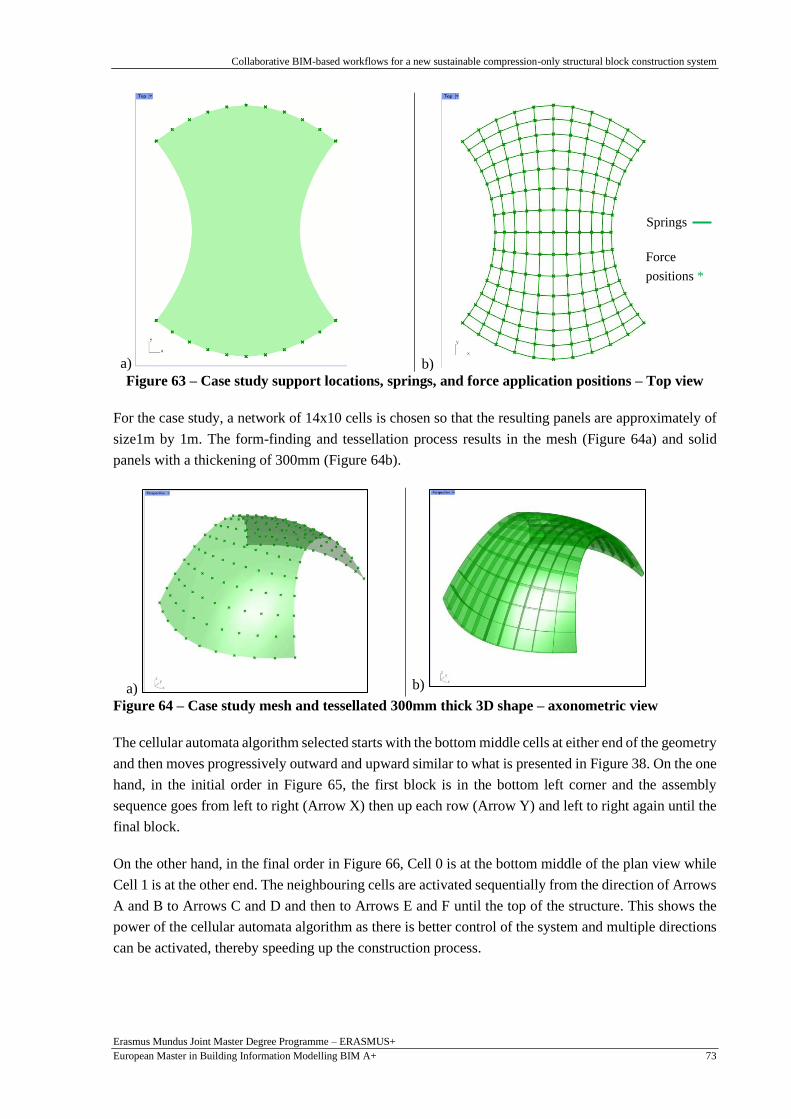
Collaborative BIM-based workflows for a new sustainable compression-only structural block construction system
Erasmus Mundus Joint Master Degree Programme – ERASMUS+
European Master in Building Information Modelling BIM A+ 73
a) b)
Figure 63 – Case study support locations, springs, and force application positions – Top view
For the case study, a network of 14x10 cells is chosen so that the resulting panels are approximately of
size1m by 1m. The form-finding and tessellation process results in the mesh (Figure 64a) and solid
panels with a thickening of 300mm (Figure 64b).
a) b)
Figure 64 – Case study mesh and tessellated 300mm thick 3D shape – axonometric view
The cellular automata algorithm selected starts with the bottom middle cells at either end of the geometry
and then moves progressively outward and upward similar to what is presented in Figure 38. On the one
hand, in the initial order in Figure 65, the first block is in the bottom left corner and the assembly
sequence goes from left to right (Arrow X) then up each row (Arrow Y) and left to right again until the
final block.
On the other hand, in the final order in Figure 66, Cell 0 is at the bottom middle of the plan view while
Cell 1 is at the other end. The neighbouring cells are activated sequentially from the direction of Arrows
A and B to Arrows C and D and then to Arrows E and F until the top of the structure. This shows the
power of the cellular automata algorithm as there is better control of the system and multiple directions
can be activated, thereby speeding up the construction process.
Springs
Force
positions *
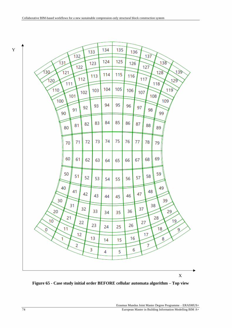
Collaborative BIM-based workflows for a new sustainable compression-only structural block construction system
Erasmus Mundus Joint Master Degree Programme – ERASMUS+
European Master in Building Information Modelling BIM A+ 74
Figure 65 - Case study initial order BEFORE cellular automata algorithm – Top view
Y
X

Collaborative BIM-based workflows for a new sustainable compression-only structural block construction system
Erasmus Mundus Joint Master Degree Programme – ERASMUS+
European Master in Building Information Modelling BIM A+ 75
Figure 66 - Case study final order AFTER cellular automata algorithm – Top view
Following the completion of Process 1, the result in Revit is shown in Figure 67. This occurs after the
activities described in Process 2 of the framework.
A B
C D
F
E

Collaborative BIM-based workflows for a new sustainable compression-only structural block construction system
Erasmus Mundus Joint Master Degree Programme – ERASMUS+
European Master in Building Information Modelling BIM A+ 76
Figure 67 - Case study – Revit model and cuttout showing PT cables, axonometric view
5.3.2. Structural description: supports, material properties and loading
After the connection to Revit, the interoperability tool discussed in Chapter 4 is used to link the geometry
and set up the analysis in DIANA and begin Process 3. As explained in Chapter 4, the geometry is
automatically transferred from Revit to DIANA using a Python script, negating the need to re-define it.
Some screenshots of the script running in DIANA are shown in Figure 68. Note that this sequence is the
same as the one from Process 1 referred to in Figure 66.
Figure 68 - Case study - Screenshots of 6 assembly stages while Python script is running in
DIANA
Once the geometry is added to the DIANA program, the next step is to assign the Boundary conditions,
material properties loading and analysis for the FEA.

Collaborative BIM-based workflows for a new sustainable compression-only structural block construction system
Erasmus Mundus Joint Master Degree Programme – ERASMUS+
European Master in Building Information Modelling BIM A+ 77
5.3.2.1. Boundary conditions
With the selected assembly sequence, the permanent supports (Figure 69) and the construction
(temporary) supports are placed on the inner boundary of the structure as shown in Figure 70.
Figure 69 – Bottom view and axonometric view of structure with permanent supports
Figure 70 - Bottom view showing permanent and temporary construction supports
Each support point as shown in Figure 70 can correspond to a support plate and each corner of the panel
can then be supported on the support plate. This was the direction taken in the study for ease of modelling
but perhaps having support plates at the centre of the corresponding panels would be easier to set up on
site. Although, adding supports can also be automated, in this case it was thought to be easier to add the
supports manually since automation involved creating the algorithm for the supports based on the
coordinates of one of the blocks.
5.3.2.2. Material properties
The material properties are automatically added to the DIANA geometry using the tool described in
Chapter 4, as follows.
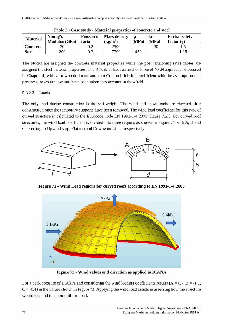
Collaborative BIM-based workflows for a new sustainable compression-only structural block construction system
Erasmus Mundus Joint Master Degree Programme – ERASMUS+
European Master in Building Information Modelling BIM A+ 78
Table 2 - Case study - Material properties of concrete and steel
Material Young's
Modulus (GPa)
Poisson's
ratio
Mass density
(kg/m3)
fyk
(MPa)
fck
(MPa)
Partial safety
factor (γ)
Concrete 30 0.2 2500 30 1.5
Steel 200 0.3 7700 450 1.15
The blocks are assigned the concrete material properties while the post tensioning (PT) cables are
assigned the steel material properties. The PT cables have an anchor force of 40kN applied, as discussed
in Chapter 4, with zero wobble factor and zero Coulomb friction coefficient with the assumption that
prestress losses are low and have been taken into account in the 40kN.
5.3.2.3. Loads
The only load during construction is the self-weight. The wind and snow loads are checked after
construction once the temporary supports have been removed. The wind load coefficient for this type of
curved structure is calculated to the Eurocode code EN 1991-1-4:2005 Clause 7.2.8. For curved roof
structures, the wind load coefficient is divided into three regions as shown in Figure 71 with A, B and
C referring to Upwind slop, Flat top and Downwind slope respectively.
Figure 71 - Wind Load regions for curved roofs according to EN 1991-1-4:2005
Figure 72 - Wind values and direction as applied in DIANA
For a peak pressure of 1.56kPa and considering the wind loading coefficients results (A = 0.7, B = -1.1,
C = -0.4) in the values shown in Figure 72. Applying the wind load assists in assessing how the structure
would respond to a non-uniform load.
1.1kPa
1.7kPa
0.6kPa
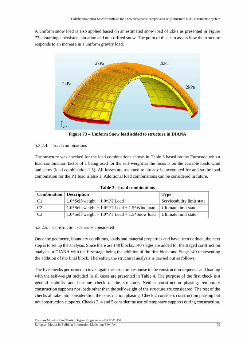
Collaborative BIM-based workflows for a new sustainable compression-only structural block construction system
Erasmus Mundus Joint Master Degree Programme – ERASMUS+
European Master in Building Information Modelling BIM A+ 79
A uniform snow load is also applied based on an estimated snow load of 2kPa as presented in Figure
73, assuming a persistent situation and non-drifted snow. The point of this is to assess how the structure
responds to an increase in a uniform gravity load.
Figure 73 – Uniform Snow load added to structure in DIANA
5.3.2.4. Load combinations
The structure was checked for the load combinations shown in Table 3 based on the Eurocode with a
load combination factor of 1 being used for the self-weight as the focus is on the variable loads wind
and snow (load combination 1.5). All losses are assumed to already be accounted for and so the load
combination for the PT load is also 1. Additional load combinations can be considered in future.
Table 3 - Load combinations
Combination Description Type
C1 1.0*Self-weight + 1.0*PT Load Serviceability limit state
C2 1.0*Self-weight + 1.0*PT Load + 1.5*Wind load Ultimate limit state
C3 1.0*Self-weight + 1.0*PT Load + 1.5*Snow load Ultimate limit state
5.3.2.5. Construction scenarios considered
Once the geometry, boundary conditions, loads and material properties and have been defined, the next
step is to set up the analysis. Since there are 140 blocks, 140 stages are added for the staged construction
analysis in DIANA with the first stage being the addition of the first block and Stage 140 representing
the addition of the final block. Thereafter, the structural analysis is carried out as follows.
The five checks performed to investigate the structure response to the construction sequence and loading
with the self-weight included in all cases are presented in Table 4. The purpose of the first check is a
general stability and baseline check of the structure. Neither construction phasing, temporary
construction supports nor loads other than the self-weight of the structure are considered. The rest of the
checks all take into consideration the construction phasing. Check 2 considers construction phasing but
not construction supports. Checks 3, 4 and 5 consider the use of temporary supports during construction.
2kPa 2kPa
2kPa 2kPa

Collaborative BIM-based workflows for a new sustainable compression-only structural block construction system
Erasmus Mundus Joint Master Degree Programme – ERASMUS+
European Master in Building Information Modelling BIM A+ 80
Table 4 – Construction scenarios
No. Description Self-
weight
Wind
Load
Snow
Load
Construction
Phasing
Construction
supports
1 Self-weight (SW) only Yes No No No No
2 SW + Construction Phasing (CP) Yes No No Yes No
3 SW + CP + Temp. Supports (TS) Yes No No Yes Yes
4 SW + CP + TS + Wind Yes Yes No Yes Yes
5 SW + CP + TS + Snow Yes No Yes Yes Yes
The construction supports are removed after the final block has been added (Stage 141). Thereafter, two
stages are added for the wind (Stage 142) and snow load (Stage 143). The first three checks are during
construction and therefore are restricted to load combination C1 with only the self-weight and the PT
load applied. The last two checks are preliminary Ultimate Limit State checks for load combinations C2
and C3 with wind and snow respectively.
5.3.3. FEA modelling and analysis
In the FEA conducted (see Section 4.4), the structural materials are assumed to be linearly elastic and a
staged construction analysis is performed. Equilibrium should be maintained, throughout the
construction stages. A simplified model is being used rather than having anchor plates for the
prestressing cables or interface elements to observe the stresses between the panels. However, there
should be no tensile stresses at the interfaces to guarantee construction stability. With more sophisticated
models (e.g. with interface elements added), tension could be acceptable if it is small and the equilibrium
is maintained. Consequently, the results will focus on the tensile stresses and two checks will be
performed. Firstly, whether the stresses will lead to concrete cracking and secondly whether the interface
stresses will cause instability and loss of equilibrium during construction.
According to the Eurocode 2 (EN 1992-1-1:2004, Design of concrete structures - Part 1-1: General rules
and rules for buildings), given a concrete grade C30/37 the characteristic cylinder compressive strength
is 30 MPa. For a fractile of 5%, the design tensile strength can be estimated as in Equation 1.
fctd, 0.05 = 0.7 x 0.30 x 𝑓ck
2/3
𝛾 = 1.35 MPa Equation 1
A quadrilateral mesh of size 75 mm was selected to reduce computational time. Although a smaller
mesh size can be used, the results were judged to be sufficiently close to those of the smaller 50mm
mesh using a small model. The mesh can be further refined in future to investigate these preliminary
results.
5.3.4. Results for Check 1: Self-weight only, no construction support and no phasing
The principal stresses S1 for self-weight of the structure only and no construction supports or phasing
are displayed in Figure 74. The maximum tensile stress is 0.004 MPa and the maximum compressive
stress is 0.046 MPa. Although not plotted here for the sake of brevity, Principal Stresses S2 and S3 are
in the range -0.447 MPa to 0 MPa and the deflections are less than 0.05mm in all directions.
The results are to be expected based on the optimised nature of the structure. However, this system
would require extensive construction supports that would significantly increase the project cost as

Collaborative BIM-based workflows for a new sustainable compression-only structural block construction system
Erasmus Mundus Joint Master Degree Programme – ERASMUS+
European Master in Building Information Modelling BIM A+ 81
discussed in Chapter 2. Therefore, the proposed construction system is investigated including
construction phasing, supports and loading in the following Sections with Checks 2 to 5 (see Table 4).
Figure 74 - Principal Stresses S1 - Self-weight only, no construction supports or phasing
5.3.5. Results for Check 2: Construction phasing but no construction supports
The next check is with the self-weight and construction phasing but with no construction supports. The
assembly sequence from the cellular automata is used to consider the effect of adding one panel at a
time. The tension stresses on the structure increase as the number of blocks in the system increase. It is
highest at the top surface, gradually decreasing with depth to the bottom surface. The maximum tensile
stress is 2.04 MPa at construction Stage 140, in the region where assembly commences (Figure 75).
Figure 75 - Principal Stresses S1 for Construction Stage 140 with no provisional supports
Top surface
Bottom surface
> 1.35 MPa

Collaborative BIM-based workflows for a new sustainable compression-only structural block construction system
Erasmus Mundus Joint Master Degree Programme – ERASMUS+
European Master in Building Information Modelling BIM A+ 82
The stresses on the structure appear as soon as a block is added and are therefore caused by both the
construction sequence as well as the post tensioning in the added block. Although, there is tension on
both the bottom and top surfaces of the blocks, the tension is higher on the top surface as would be
expected for this type of structure. The highest tension is for principal stresses S1. Although, the stresses
are still generally less than 0.1 MPa, there is more tension in the structure with the introduction of
construction phasing than before (Figure 74) and some areas of tension are greater than 1.35 MPa and
will likely cause cracking. Therefore, it is necessary to add provisional construction supports to the
system.
5.3.6. Results for Check 3: Construction phasing and construction supports
The third check is for load combination C1, with construction supports, and construction phasing added.
This is the most important check as it evaluates how the structure behaves during construction of the
proposed system. The construction supports are added along the middle centre of the structure as shown
in Figure 70 and the structure is checked for possibility of cracking, interface stresses, deflections and
bending moments.
5.3.6.1. Possibility of cracks during construction
This check is to determine if the tension on the structure is enough to cause cracks i.e. are the tensions
greater than the design tensile strength of 1.35 MPa? With the use of construction supports, there is a
reduction in tension throughout the construction phases as seen in Figure 76 compared to Figure 75.
Parts of the system are in compression, but most parts are in tension. From the early stages of the
construction (Figure 76), the tension in the system is at a maximum of 0.41 MPa. The tension increases
steadily with the addition of each block until the tension is at a maximum of 0.78 MPa in Stage 140
(Figure 77) as opposed to the Check 2 where it was more than twice as high at 2 MPa.
Figure 76 – Principal Stresses S1 for Check 3 during early construction (1)

Collaborative BIM-based workflows for a new sustainable compression-only structural block construction system
Erasmus Mundus Joint Master Degree Programme – ERASMUS+
European Master in Building Information Modelling BIM A+ 83
Figure 77 – Principal Stresses S1 for Check 3 during construction (2)
The maximum tension is generally less than 0.34 MPa in most areas from Construction Stage 1 to Stage
140 when the last panel is placed. However, there are points in the centre of the system at the corners of
the panels that have higher tension (> 0.68 MPa) that are due to the provisional supports and in the
regions where the cable anchors would be - anchor plates were not added to make the model lighter
(Figure 77). These tensions will not be transmitted to the structure and will be taken up by the provisional
support system and anchor plates. Nonetheless, it is evident that the tensions on the structure will not
cause cracking as they are less than 1.35 MPa.
5.3.6.2. Possibility of instability due to interface tensions during construction
The interface refers to the surface-to-surface connection between panels (refer to Section 4.2.2). This to
evaluate the stability in the structure during construction and check the validity of the model. Since the
structure is symmetric in two directions, the stresses will be similar for each half of the structure. The
interface principal stresses S1 during Construction Stage 140 are shown in Figure 79 and Figure 80 with
the former showing the long side and the latter showing the short side of the centre of the structure. In
both cases, the level of tension increases steadily from outward to inward blocks of the slice. (In the
construction sequence, the inner blocks were added first and therefore have higher tensile stresses).
In reference to Figure 79 and Figure 80, generally, the outer block stresses are more than 90 percent less
than 0.15 MPa. In the middle blocks, although they are less than ten percent of the cross-sectional area,
the regions of tension with higher stresses increase to between 0.15 MPa and 0.29 MPa. Similarly, on
the top blocks, less than ten percent of the area have tensions greater than 0.29 MPa.
≥ 0.68 MPa

Collaborative BIM-based workflows for a new sustainable compression-only structural block construction system
Erasmus Mundus Joint Master Degree Programme – ERASMUS+
European Master in Building Information Modelling BIM A+ 84
Figure 78 – Central Interface stresses during Construction Stage 140 (1)
Figure 79 – Central Interface stresses during Construction Stage 140 (2)
Figure 80 – Block A Interface stresses at Construction Stage 140
Block A
≤ 0 MPa
≤ 0.15 MPa
≤ 0.44MPa
300mm
≤ 0.29 MPa
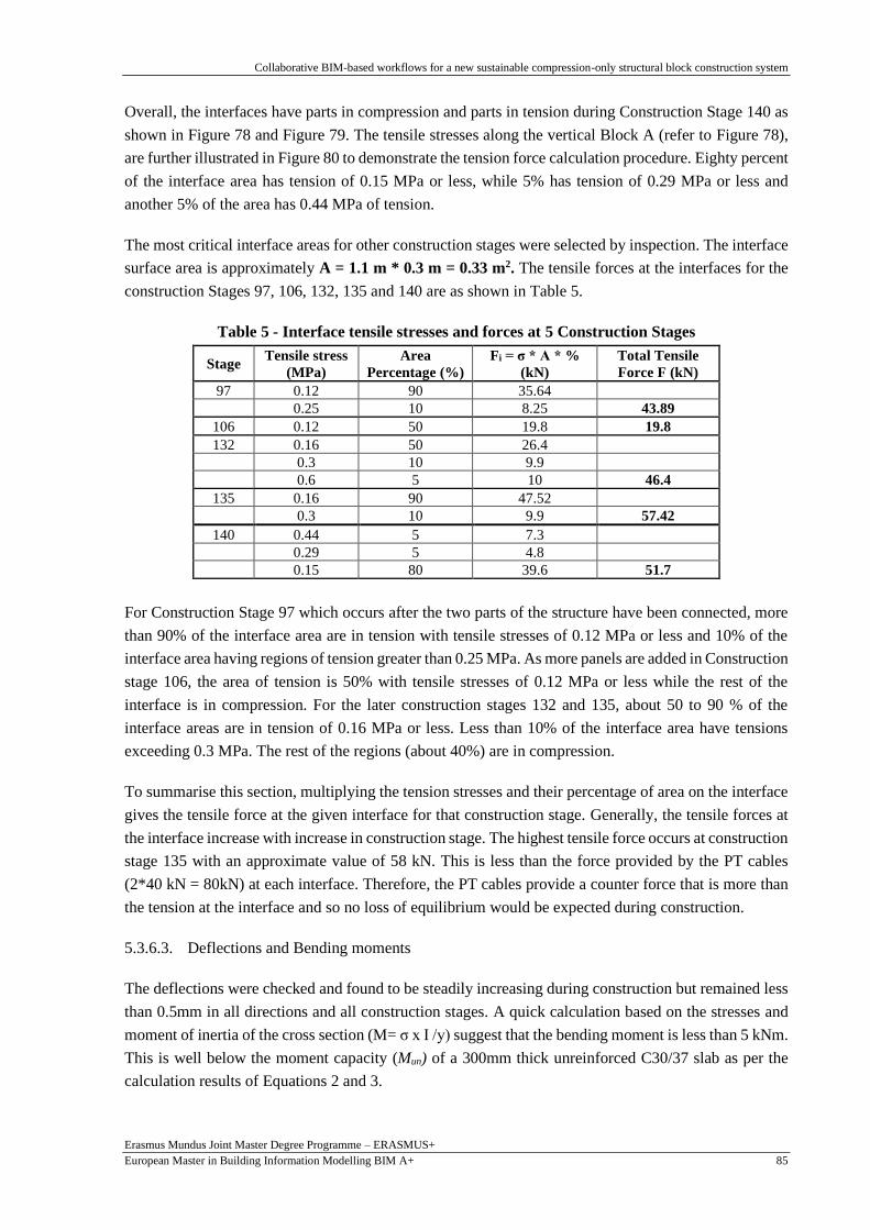
Collaborative BIM-based workflows for a new sustainable compression-only structural block construction system
Erasmus Mundus Joint Master Degree Programme – ERASMUS+
European Master in Building Information Modelling BIM A+ 85
Overall, the interfaces have parts in compression and parts in tension during Construction Stage 140 as
shown in Figure 78 and Figure 79. The tensile stresses along the vertical Block A (refer to Figure 78),
are further illustrated in Figure 80 to demonstrate the tension force calculation procedure. Eighty percent
of the interface area has tension of 0.15 MPa or less, while 5% has tension of 0.29 MPa or less and
another 5% of the area has 0.44 MPa of tension.
The most critical interface areas for other construction stages were selected by inspection. The interface
surface area is approximately A = 1.1 m * 0.3 m = 0.33 m2. The tensile forces at the interfaces for the
construction Stages 97, 106, 132, 135 and 140 are as shown in Table 5.
Table 5 - Interface tensile stresses and forces at 5 Construction Stages
Stage Tensile stress
(MPa)
Area
Percentage (%)
Fi = σ * A * %
(kN)
Total Tensile
Force F (kN)
97 0.12 90 35.64
0.25 10 8.25 43.89
106 0.12 50 19.8 19.8
132 0.16 50 26.4
0.3 10 9.9 0.6 5 10 46.4
135 0.16 90 47.52
0.3 10 9.9 57.42
140 0.44 5 7.3
0.29 5 4.8
0.15 80 39.6 51.7
For Construction Stage 97 which occurs after the two parts of the structure have been connected, more
than 90% of the interface area are in tension with tensile stresses of 0.12 MPa or less and 10% of the
interface area having regions of tension greater than 0.25 MPa. As more panels are added in Construction
stage 106, the area of tension is 50% with tensile stresses of 0.12 MPa or less while the rest of the
interface is in compression. For the later construction stages 132 and 135, about 50 to 90 % of the
interface areas are in tension of 0.16 MPa or less. Less than 10% of the interface area have tensions
exceeding 0.3 MPa. The rest of the regions (about 40%) are in compression.
To summarise this section, multiplying the tension stresses and their percentage of area on the interface
gives the tensile force at the given interface for that construction stage. Generally, the tensile forces at
the interface increase with increase in construction stage. The highest tensile force occurs at construction
stage 135 with an approximate value of 58 kN. This is less than the force provided by the PT cables
(2*40 kN = 80kN) at each interface. Therefore, the PT cables provide a counter force that is more than
the tension at the interface and so no loss of equilibrium would be expected during construction.
5.3.6.3. Deflections and Bending moments
The deflections were checked and found to be steadily increasing during construction but remained less
than 0.5mm in all directions and all construction stages. A quick calculation based on the stresses and
moment of inertia of the cross section (M= σ x I /y) suggest that the bending moment is less than 5 kNm.
This is well below the moment capacity (Mun) of a 300mm thick unreinforced C30/37 slab as per the
calculation results of Equations 2 and 3.

Collaborative BIM-based workflows for a new sustainable compression-only structural block construction system
Erasmus Mundus Joint Master Degree Programme – ERASMUS+
European Master in Building Information Modelling BIM A+ 86
fctd, fl = fctm x (1.6 - ℎ
1000 ) / γ Equation 2
Mun = fctd,fl x ( ℎ2
6 ) Equation 3
Mean axial tensile strength; fctm = 2.9 MPa
Design flexural tensile strength of concrete; f'ctd,fl = 2.51 MPa
Moment capacity per m of unreinforced slab; Mun = 38 kNm
5.3.7. Results for Check 4: Wind Load
The fourth check is for load combination C2, which considers wind loading after construction. The
principal stresses for S1 and S2 of the overall structure for this check are displayed in Figure 81 and
Figure 82 respectively. Note that this is after the removal of the temporary construction supports.
Figure 81 – Principal stresses S1 for Wind Load after construction
Figure 82 - Principal stresses S2 for Wind Load after construction
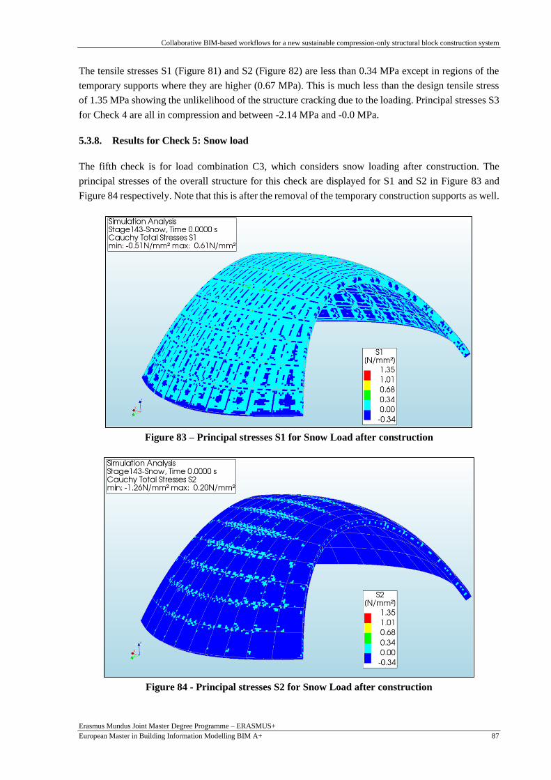
Collaborative BIM-based workflows for a new sustainable compression-only structural block construction system
Erasmus Mundus Joint Master Degree Programme – ERASMUS+
European Master in Building Information Modelling BIM A+ 87
The tensile stresses S1 (Figure 81) and S2 (Figure 82) are less than 0.34 MPa except in regions of the
temporary supports where they are higher (0.67 MPa). This is much less than the design tensile stress
of 1.35 MPa showing the unlikelihood of the structure cracking due to the loading. Principal stresses S3
for Check 4 are all in compression and between -2.14 MPa and -0.0 MPa.
5.3.8. Results for Check 5: Snow load
The fifth check is for load combination C3, which considers snow loading after construction. The
principal stresses of the overall structure for this check are displayed for S1 and S2 in Figure 83 and
Figure 84 respectively. Note that this is after the removal of the temporary construction supports as well.
Figure 83 – Principal stresses S1 for Snow Load after construction
Figure 84 - Principal stresses S2 for Snow Load after construction

Collaborative BIM-based workflows for a new sustainable compression-only structural block construction system
Erasmus Mundus Joint Master Degree Programme – ERASMUS+
European Master in Building Information Modelling BIM A+ 88
Similar to the wind load results, the tensile stresses S1 (Figure 83) and S2 (Figure 84) are less than 0.34
MPa except in regions of the temporary supports where they are higher (0.67 MPa). This is much less
than the design tensile stress of 1.35 MPa so it is unlikely that the structure will crack due to the loading.
Principal stresses S3 for Check 5 are all in compression and between -2.15 MPa and -0.05 MPa.
5.3.9. Photo montage of case study
The photo montage shown in Figure 85 can be a real-life application of the case study presented in this
chapter. The construction system is visible with the approximately 1 m x 1 m x 0.3 m concrete panels
joined by PT cables in each direction. This illustrates the aesthetically pleasing aspect of the construction
system.
Figure 85 - Photo montage of case study, Parque da Cidade, Guimarães
5.4. Other applications of framework
Three further structural shapes are presented to illustrate the versatility and variety of structural shapes
that can be produced using the framework described in this chapter.
5.4.1. Exhibit A
The first application (Exhibit A), results in an igloo-like structure (refer to Figure 86). Referring to
Process 1, starting with an arbitrary planar surface and selecting some supports, the form-finding method
can be carried out. The cables can then be added to the structure corresponding to the appropriate panel
using the cellular automata algorithm and then the structure can be tessellated and thickened as desired
(refer to Figure 86c and d).

Collaborative BIM-based workflows for a new sustainable compression-only structural block construction system
Erasmus Mundus Joint Master Degree Programme – ERASMUS+
European Master in Building Information Modelling BIM A+ 89
a) Starting surface - Top view b) Support positions – Top view
c) Cable lines – axonometric view d) 3D tessellated structure
Figure 86 – Exhibit A: Rhino 3D results
Additionally, Process 2 of the framework i.e. the BIM modelling, and Process 3, i.e. the structural
analysis processes can also be carried out. The models in their respective software programs are shown
in Figure 87 and Figure 88 respectively.
Figure 87 - Exhibit A: Autodesk Revit result – 3D model
5 m
7 m

Collaborative BIM-based workflows for a new sustainable compression-only structural block construction system
Erasmus Mundus Joint Master Degree Programme – ERASMUS+
European Master in Building Information Modelling BIM A+ 90
Figure 88 - Exhibit A: DIANA result – 3D model
5.4.2. Exhibit B
In the same way, Exhibit B can also be produced. With an initially four-sided surface and selecting the
four corners as supports, the framework results from the parametric modelling and computational design
(Figure 89), BIM (Figure 90) and structural analysis (Figure 91) procedures are shown.
Figure 89 - Exhibit B: Rhino 3D result
Figure 90 - Exhibit B: Autodesk Revit Result
10m
10m

Collaborative BIM-based workflows for a new sustainable compression-only structural block construction system
Erasmus Mundus Joint Master Degree Programme – ERASMUS+
European Master in Building Information Modelling BIM A+ 91
Figure 91 - Exhibit B: DIANA model
5.4.3. Exhibit C and Photo Montage
Another application would be a shading structure also at Parque da Cidade, in Guimarães, Portugal (refer
to Figure 92 to Figure 96). The structure would provide all the features proposed in the thesis. For
instance, an integrated approach through the collaborative BIM-based workflow proposed herein would
be used to design it saving time and cost. During construction, it would be largely self-supporting, and
the cellular automata algorithm could be used to automate and optimise the construction assembly
procedure. And finally, it would be durable and long lasting due to the use of maritime cables as opposed
to steel reinforcement.
Figure 92 - Exhibit C: Panels in Rhino
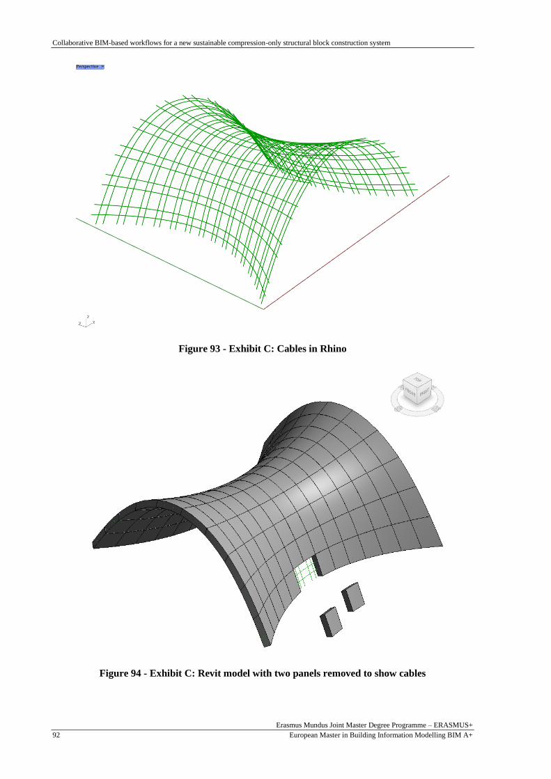
Collaborative BIM-based workflows for a new sustainable compression-only structural block construction system
Erasmus Mundus Joint Master Degree Programme – ERASMUS+
European Master in Building Information Modelling BIM A+ 92
Figure 93 - Exhibit C: Cables in Rhino
Figure 94 - Exhibit C: Revit model with two panels removed to show cables
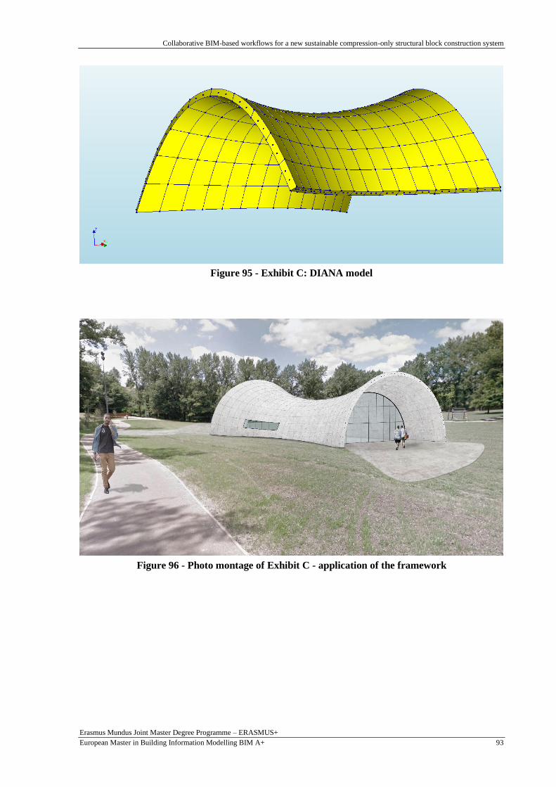
Collaborative BIM-based workflows for a new sustainable compression-only structural block construction system
Erasmus Mundus Joint Master Degree Programme – ERASMUS+
European Master in Building Information Modelling BIM A+ 93
Figure 95 - Exhibit C: DIANA model
Figure 96 - Photo montage of Exhibit C - application of the framework

Collaborative BIM-based workflows for a new sustainable compression-only structural block construction system
Erasmus Mundus Joint Master Degree Programme – ERASMUS+
European Master in Building Information Modelling BIM A+ 94
This page is intentionally left blank

Collaborative BIM-based workflows for a new sustainable compression-only structural block construction system
Erasmus Mundus Joint Master Degree Programme – ERASMUS+
European Master in Building Information Modelling BIM A+ 95
6. CONCLUSION
This work presented a collaborative BIM-based framework for a new sustainable compression-only
structural block construction system. The introduction also included a description of the Perpectum
concept (Azenha, 2019) which had been theorized in 2019, but never really implemented. It was
followed by a literature review of sustainability and optimisation in construction and how this relates to
shell structures and their sustainable design, including their incorporation into BIM processes.
Subsequently, there was a description of the parametric modelling and computational design processes
that were carried out. A simple geometry was used to explain the procedures, including the one for
obtaining the construction sequence using customised cellular automata principles and a description of
the connection tool from the CAD to BIM platform. Next, the interoperability tools defined for structural
analysis connection with the BIM platform and the one for automating the construction phasing were
described. Finally, there was a description of the proposed framework for collaborative BIM-based
workflows for the compression-only structural block construction system.
A case study was used to perform the procedures proposed in the framework including carrying out the
computational design and form-finding (Process 1), producing the BIM model (Process 2) and carrying
out FEA (Process 3). With the 3D printing of the case study, Technology Readiness Level (TRL) 2 and
3 could be said to have been achieved, with the technological concept ormulated, and an experimental
proof of concept provided.
The results based on the objectives in the introduction are as follows:
• Using the visual programming software Grasshopper 3D in Rhino 3D, simplified Process 1. An
understanding of the list system and nomenclature of the Rhino 3D platform is necessary to
optimise the process. The “Food for Rhino” plug-ins can be used to further assist in carrying
out the tasks required such as the form-finding (Kangaroo) and cellular automata algorithm
(Anemone). Once the program has been set up, only minor adjustments are required to quickly
make changes due to the parametric nature of the model.
• In Process 2, Rhino.Inside.Revit provided direct interoperability from Rhino 3D to Autodesk
Revit. Due to the requirements of the structural analysis software, it was necessary to first have
the cables as lines. Thereafter, further computational modelling could be carried out to add
openings and have the cable lines thickened for BIM modelling purposes. After that, metadata
can be added to the model as required.
• An interoperability tool was used which accessed the Autodesk Revit API via C# for Process 3.
It automated the creation of a Python script that transformed the geometry from Revit
nomenclature to structural analysis software DIANA nomenclature. Then, another Python script
was created which automated the materials property assignment and construction phasing
analysis in DIANA.
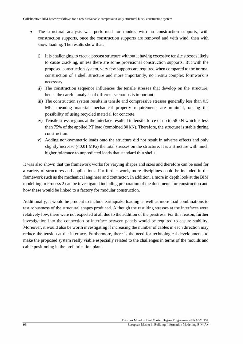
Collaborative BIM-based workflows for a new sustainable compression-only structural block construction system
Erasmus Mundus Joint Master Degree Programme – ERASMUS+
European Master in Building Information Modelling BIM A+ 96
• The structural analysis was performed for models with no construction supports, with
construction supports, once the construction supports are removed and with wind, then with
snow loading. The results show that:
i) It is challenging to erect a precast structure without it having excessive tensile stresses likely
to cause cracking, unless there are some provisional construction supports. But with the
proposed construction system, very few supports are required when compared to the normal
construction of a shell structure and more importantly, no in-situ complex formwork is
necessary.
ii) The construction sequence influences the tensile stresses that develop on the structure;
hence the careful analysis of different scenarios is important.
iii) The construction system results in tensile and compressive stresses generally less than 0.5
MPa meaning material mechanical property requirements are minimal, raising the
possibility of using recycled material for concrete.
iv) Tensile stress regions at the interface resulted in tensile force of up to 58 kN which is less
than 75% of the applied PT load (combined 80 kN). Therefore, the structure is stable during
construction.
v) Adding non-symmetric loads onto the structure did not result in adverse effects and only
slightly increase (<0.01 MPa) the total stresses on the structure. It is a structure with much
higher tolerance to unpredicted loads that standard thin shells.
It was also shown that the framework works for varying shapes and sizes and therefore can be used for
a variety of structures and applications. For further work, more disciplines could be included in the
framework such as the mechanical engineer and contractor. In addition, a more in depth look at the BIM
modelling in Process 2 can be investigated including preparation of the documents for construction and
how these would be linked to a factory for modular construction.
Additionally, it would be prudent to include earthquake loading as well as more load combinations to
test robustness of the structural shapes produced. Although the resulting stresses at the interfaces were
relatively low, there were not expected at all due to the addition of the prestress. For this reason, further
investigation into the connection or interface between panels would be required to ensure stability.
Moreover, it would also be worth investigating if increasing the number of cables in each direction may
reduce the tension at the interface. Furthermore, there is the need for technological developments to
make the proposed system really viable especially related to the challenges in terms of the moulds and
cable positioning in the prefabrication plant.

Collaborative BIM-based workflows for a new sustainable compression-only structural block construction system
Erasmus Mundus Joint Master Degree Programme – ERASMUS+
European Master in Building Information Modelling BIM A+ 97
REFERENCES
Abdelmageed, S. and Zayed, T. (2020) ‘A study of literature in modular integrated construction - Critical
review and future directions’, Journal of Cleaner Production, 277, p. 124044. doi:
10.1016/j.jclepro.2020.124044.
Adriaenssens, S. et al. (2014) Shell structures for architecture: Form finding and optimization, Shell
Structures for Architecture: Form Finding and Optimization. doi: 10.4324/9781315849270.
Akbarzadeh, M., Van Mele, T. and Block, P. (2014) ‘Compression-only Form finding through Finite
Subdivision of the Force Polygon’, in Brasil, Reyolando, M. L. R. . and Pauletti, R. M. O. (eds)
Proceedings of the IASS-SLTE 2014 Symposium: “Shells, Membranes and Spatial Structures:
Footprints”. Brasilia.
Alexander, M. G. and Nganga, G. (2014) ‘Reinforced concrete durability: some recent developments in
performance-based approaches’, Journal of Sustainable Cement-Based Materials, 3(1), pp. 1–12. doi:
10.1080/21650373.2013.876372.
Azenha, M. (2019) ‘Horizon 2020 Excellent Science ( Call for proposals for ERC Consolidator Grant )
Topic : ERC-2019-COG Type of action : ERC-COG Call : ERC-2019-COG Proposal number : 864027
Proposal acronym : Brillouin4Life Deadline Id : ERC-2019-COG Table of contents’. Braga, pp. 1–52.
Bao, Y. and Li, V. C. (2020) ‘Feasibility study of lego-inspired construction with bendable concrete’,
Automation in Construction, 113(September 2019), p. 103161. doi: 10.1016/j.autcon.2020.103161.
Barbosa, F. et al. (2017) Reinventing Construction: A Route To Higher Productivity, Mckinsey’s Capital
Projects and Infrastructure Practice. Available at: http://www.mckinsey.com/industries/capital-
projects-and-infrastructure/our-insights/reinventing-construction-through-a-productivity-revolution.
Bathe, K.-J. (2010) ‘RES.2-002 Finite Element Procedures for Solids and Structures. Spring 2010’.
Massachusetts Institute of Technology: MIT OpenCourseWare, https://ocw.mit.edu. Available at:
https://ocw.mit.edu/resources/res-2-002-finite-element-procedures-for-solids-and-structures-spring-
2010/.
Belton, P. (2021) Building’s hard problem - making concrete green, BBC Technology of Business.
Available at: https://www.bbc.com/news/business-56716859 (Accessed: 9 August 2021).
Bertram, N. et al. (2019) Modular construction: From projects to products, McKinsey & Company:
Capital Projects & Infrastructure. Available at: https://www.mckinsey.com/industries/capital-projects-
and-infrastructure/our-insights/modular-construction-from-projects-to-products.
Borg Costanzi, C. et al. (2018) ‘3D Printing Concrete on temporary surfaces: The design and fabrication
of a concrete shell structure’, Automation in Construction, 94(August 2017), pp. 395–404. doi:
10.1016/j.autcon.2018.06.013.
Congiu, E., Fenu, L. and Briseghella, B. (2021) ‘Comparison of Form-finding Methods to Shape
Concrete Shells for Curved Footbridges’, Structural Engineering International. doi:
10.1080/10168664.2021.1878974.
Correia, R. (2021) Serviceability assessment of reinforced concrete buildings with non-linear analysis,
based on information generated by BIM models. Universita do Minho.
Dallinger, S. and Kollegger, J. (2008) ‘Thin post-tensioned concrete shell structures’, in Proceedings of
the International FIB Symposium 2008 - Tailor Made Concrete Structures: New Solutions for our

Collaborative BIM-based workflows for a new sustainable compression-only structural block construction system
Erasmus Mundus Joint Master Degree Programme – ERASMUS+
European Master in Building Information Modelling BIM A+ 98
Society, p. 158. doi: 10.1201/9781439828410.ch114.
Davis, D. (2013) Modelled on Software Engineering: Flexible Parametric Models in the Practice of
Architecture. RMIT University.
Eastman, C. (1974) An outline of the Building Description System, Pennsylvania Institute of Physical
Planning. Pittsburg.
Fernandes, L. P. B. (2015) An integrated model for simulation of contruction phasing of arch concrete
dams. University do Minho.
Goldbach, A. K. et al. (2020) ‘CAD-Integrated Parametric Lightweight Design With Isogeometric B-
Rep Analysis’, Frontiers in Built Environment, 6(April), pp. 1–11. doi: 10.3389/fbuil.2020.00044.
Gomes, C. et al. (2018) ‘An integrated framework for multi-criteria optimization of thin concrete shells
at early design stages’, Advanced Engineering Informatics, 38(June), pp. 330–342. doi:
10.1016/j.aei.2018.08.003.
Gomes, C. (2021) ‘Design Optimisation and Simulation’. Braga: BIM A+ Module 3: Parametric
Modelling in BIM Lecture.
Hadilou, A. (2014) ‘Flexible formwork: a methodology for casting funicular structures’, in Digital
Crafting [7th International Conference Proceedings of the Arab Society for Computer Aided
Architectural Design (ASCAAD 2014).
Herr, C. M. and Kvan, T. (2007) ‘Adapting cellular automata to support the architectural design
process’, Automation in Construction, 16(1), pp. 61–69. doi: 10.1016/j.autcon.2005.10.005.
Hughes, T. J. R., Cottrell, J. A. and Bazilevs, Y. (2005) ‘Isogeometric analysis: CAD, finite elements,
NURBS, exact geometry and mesh refinement’, Computer Methods in Applied Mechanics and
Engineering, 194(39–41), pp. 4135–4195. doi: 10.1016/j.cma.2004.10.008.
Iacovidou, E. et al. (2021) ‘Digitally enabled modular construction for promoting modular components
reuse: A UK view’, Journal of Building Engineering, 42(June), p. 9. doi: 10.1016/j.jobe.2021.102820.
Kontovourkis, O., Phocas, M. C. and Katsambas, C. (2019) ‘Digital to physical development of a
reconfigurable modular formwork for concrete casting and assembling of a shell structure’, Automation
in Construction, 106(July), p. 23. doi: 10.1016/j.autcon.2019.102855.
Lock Block (2021) Lock Block Homepage, Lock Block Ltd. Available at: https://www.lockblock.com/
(Accessed: 23 August 2021).
Lomholt, I. (2021) ‘Striatus Masonry Footbridge in Venice: Zaha Hadid Architects’, e-architect.
Available at: https://www.e-architect.com/venice/striatus-masonry-footbridge-venice.
Long, A. et al. (2014) ‘FlexiArch: From concept to practical applications’, Structural Engineer, 92(7),
pp. 10–15.
Lopez, D. and Froese, T. M. (2016) ‘Analysis of Costs and Benefits of Panelized and Modular
Prefabricated Homes’, Procedia Engineering, 145, pp. 1291–1297. doi: 10.1016/j.proeng.2016.04.166.
Nassar, K. and Aly, E. A. (2012) ‘Automated planning and design of formwork for freeform shell
structures’, in Construction Research Congress 2012: Construction Challenges in a Flat World,
Proceedings of the 2012 Construction Research Congress, pp. 1165–1174. doi:
10.1061/9780784412329.117.

Collaborative BIM-based workflows for a new sustainable compression-only structural block construction system
Erasmus Mundus Joint Master Degree Programme – ERASMUS+
European Master in Building Information Modelling BIM A+ 99
Pedersen, O. E., Larsen, N. M. and Pigram, D. (2015) ‘Post-tensioned Discrete Concrete Elements
Developed For Free-form Construction’, in Block, P. et al. (eds) Advances in Architectural Geometry
2014. London. doi: 10.1007/978-3-319-11418-7.
Polat, G. (2008) ‘Factors Affecting the Use of Precast Concrete Systems in the United States’, Journal
of Construction and Engineering Management, 134(3), pp. 169–178. doi: 10.1061/(asce)1076-
0431(2000)6:3(79).
Popescu, M. et al. (2021) ‘Structural design, digital fabrication and construction of the cable-net and
knitted formwork of the KnitCandela concrete shell’, Structures, 31(January 2020), pp. 1287–1299. doi:
10.1016/j.istruc.2020.02.013.
Ribeirinho, M. J. et al. (2020) The next normal in construction, McKinsey & Company.
Rippmann, M. and Block, P. (2013) ‘Funicular shell design exploration’, in ACADIA 2013: Adaptive
Architecture - Proceedings of the 33rd Annual Conference of the Association for Computer Aided
Design in Architecture, pp. 337–346.
Schuster, P. (2017) FEA 01: What is FEA? Available at:
https://www.youtube.com/watch?v=sSaUHDQf204 (Accessed: 11 August 2021).
Schwaber, K. and Sutherland, J. (2015) The Scrum Guide, Software in 30 Days. doi:
10.1002/9781119203278.app2.
Shay Murtagh (2021) Shay Murtagh Homepage, Shay Murtagh. Available at:
https://www.shaymurtagh.co.uk/precast-concrete-products/tunnel-segments/ (Accessed: 23 August
2021).
Stasiuk, D. (2018) ‘Design Modeling Terminology’, Proving Ground, p. 6.
Stout, J. (2021) ‘Shetland fires “should act as warning to modular building industry”’, BBC News.
Available at: https://www.bbc.com/news/uk-scotland-north-east-orkney-shetland-57942459.
Tomás, A. and Martí, P. (2010) ‘Shape and size optimisation of concrete shells’, Engineering Structures,
32(6), pp. 1650–1658. doi: 10.1016/j.engstruct.2010.02.013.
Turner & Townsend (2018) International construction market survey 2018, Global rebalancing: a
changing landscape.
United Nations (2015) 17 Sustainable Development Goals, Department of Economic and Social Affairs.
Available at: https://sdgs.un.org/goals (Accessed: 24 August 2021).
Veenendaal, D. and Block, P. (2012) ‘An overview and comparison of structural form finding methods
for general networks’, International Journal of Solids and Structures, 49(26), pp. 3741–3753. doi:
10.1016/j.ijsolstr.2012.08.008.
Vizotto, I. (2010) ‘Computational generation of free-form shells in architectural design and civil
engineering’, Automation in Construction, 19(8), pp. 1087–1105. doi: 10.1016/j.autcon.2010.09.004.
Webb, S. (2021) Structural issues: the cost of material and the value of labour, Architectural Review.
Available at: https://www.architectural-review.com/essays/structural-issues-the-cost-of-material-and-
the-value-of-labour (Accessed: 9 August 2021).
World Economic Forum (2018) An Action Plan to Accelerate Building Information Modeling (BIM)
Adoption, World Economic Forum.
Collaborative BIM-based workflows for a new sustainable compression-only structural block construction system
Erasmus Mundus Joint Master Degree Programme – ERASMUS+
European Master in Building Information Modelling BIM A+ 100
Zingoni, A. and Enoma, N. (2020) ‘Dual-purpose concrete domes: A strategy for the revival of thin
concrete shell roofs’, Structures, 28(November), pp. 2686–2703. doi: 10.1016/j.istruc.2020.10.067.
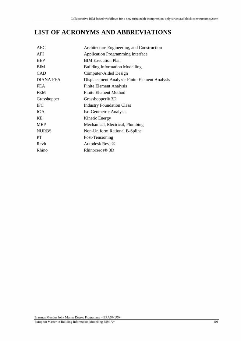
Collaborative BIM-based workflows for a new sustainable compression-only structural block construction system
Erasmus Mundus Joint Master Degree Programme – ERASMUS+
European Master in Building Information Modelling BIM A+ 101
LIST OF ACRONYMS AND ABBREVIATIONS
AEC Architecture Engineering, and Construction
API Application Programming Interface
BEP BIM Execution Plan
BIM Building Information Modelling
CAD Computer-Aided Design
DIANA FEA Displacement Analyzer Finite Element Analysis
FEA Finite Element Analysis
FEM Finite Element Method
Grasshopper Grasshopper® 3D
IFC Industry Foundation Class
IGA Iso-Geometric Analysis
KE Kinetic Energy
MEP Mechanical, Electrical, Plumbing
NURBS Non-Uniform Rational B-Spline
PT Post-Tensioning
Revit Autodesk Revit®
Rhino Rhinoceros® 3D

Collaborative BIM-based workflows for a new sustainable compression-only structural block construction system
Erasmus Mundus Joint Master Degree Programme – ERASMUS+
European Master in Building Information Modelling BIM A+ 102
This page is intentionally left blank

Collaborative BIM-based workflows for a new sustainable compression-only structural block construction system
Erasmus Mundus Joint Master Degree Programme – ERASMUS+
European Master in Building Information Modelling BIM A+ 103
APPENDICES
APPENDIX 1: PYTHON SCRIPT FOR DIANA AUTOMATIC
PROPERTY ASSIGNMENT AND CONSTRUCTION PHASING
############################################################################## # Program to automate assignment of properties in DIANA # Python 3.7.3 # By Lombe Mutale with input from Prof. MA, Prof. BF & CG ############################################################################## setUnit( "LENGTH", "MM" ) setUnit( "FORCE", "N" ) #Create materials addMaterial( "Concrete", "CONCR", "LEI", [] ) setParameter( "MATERIAL", "Concrete", "LINEAR/ELASTI/YOUNG", 30000 ) setParameter( "MATERIAL", "Concrete", "LINEAR/MASS/DENSIT", 2.5e-09 ) setParameter( "MATERIAL", "Concrete", "LINEAR/ELASTI/POISON", 0.2 ) addMaterial( "Steel", "REINFO", "LINEAR", [ "FRLGTH", "NOBOND" ] ) setParameter( "MATERIAL", "Steel", "LINEAR/ELASTI/YOUNG", 200000 ) setParameter( "MATERIAL", "Steel", "FREELE/FRLGTH", 1 ) #add Selfweight addSet( "GEOMETRYLOADSET", "Dead load" ) createModelLoad( "Global Load 1", "Dead load" ) #add PT loads addSet( "GEOMETRYLOADSET", "PT load" ) createBodyLoad( "PT load", "PT load" ) setParameter( "GEOMETRYLOAD", "PT load", "LODTYP", "POSTEN" ) setParameter( "GEOMETRYLOAD", "PT load", "POSTEN/TENTYP", "ONEEND" ) setParameter( "GEOMETRYLOAD", "PT load", "POSTEN/ONEEND/FORCE1", 40000 ) setParameter( "GEOMETRYLOAD", "PT load", "POSTEN/SHEAR", 0 ) nB = 140 #ENTER NUMBER OF BLOCKS nC = nB*4 noOfBlocks = range(1,nB+1) noOfCables = range(1,nC+1) #noOfSupports = [1, 2, 3, 5, 9, 10, 19, 20, 21, 22, 35, 36, 37, 38, 55, 56, 57, 58, 79, 80] #ENTER BLOCKS WITH SUPPORTS or add manually in DIANA listSizeCables = len(noOfCables) noOfCablesInBlocks = range(1, nC, 4) rename( "SHAPESET", "Shapes", "Blocks" ) #ASSIGN CABLE PROPERTIES for Cn in noOfCables: setShapeType( "REINFORCEMENTSHAPE", [ "Cable"+str(Cn)] ) addGeometry( "Cable"+str(Cn), "RELINE", "REBAR", [] ) setParameter( "GEOMET", "Cable"+str(Cn), "REIEMB/CROSSE", 140 ) setReinforcementType( "REINFORCEMENTSHAPE", ["Cable"+str(Cn) ], "BAR" ) assignMaterial( "Steel", "REINFORCEMENTSHAPE", [ "Cable"+str(Cn) ] ) assignGeometry( "Cable"+str(Cn), "REINFORCEMENTSHAPE", [ "Cable"+str(Cn)] ) #ASSIGN BLOCK PROPERTIES for Bn in noOfBlocks: setElementClassType( "SHAPE", [ "Block"+str(Bn)], "STRSOL" ) assignMaterial( "Concrete", "SHAPE", [ "Block"+str(Bn) ] ) #add Blocks to set moveToShapeSet( [ "Block"+str(Bn)], "Blocks" )

Collaborative BIM-based workflows for a new sustainable compression-only structural block construction system
Erasmus Mundus Joint Master Degree Programme – ERASMUS+
European Master in Building Information Modelling BIM A+ 104
#ASSIGN BLOCK PROPERTIES for Bn in noOfBlocks: setElementClassType( "SHAPE", [ "Block"+str(Bn)], "STRSOL" ) assignMaterial( "Concrete", "SHAPE", [ "Block"+str(Bn) ] ) #add Blocks to set moveToShapeSet( [ "Block"+str(Bn)], "Blocks" ) #Relate cables to Blocks addSet( "GEOMETRYREINFOSET", "Reinforcements"+str(Bn) ) rename( "SHAPESET", "Reinforcements"+str(Bn), "Cables Block"+str(Bn) ) ASSIGN REBAR PROPERTIES for CBn in noOfCablesInBlocks: moveToShapeSet( [ "Cable"+str(CBn), "Cable"+str(CBn+1), "Cable"+str(CBn+2), "Cable"+str(CBn+3)], "Cables Block"+str(int(CBn/4+1)) ) #add loads - VERTICAL CABLES attachTo( "GEOMETRYLOAD", "PT load", "POSTEN/ONEEND/PNTS1", "Cable"+str(CBn), [[ 4367.39, -1948.74, 11.7079 ]] ) #ADD COODINATES OF FIRST END attach( "GEOMETRYLOAD", "PT load", [ "Cable"+str(CBn) ] ) attachTo( "GEOMETRYLOAD", "PT load", "POSTEN/ONEEND/PNTS1", "Cable"+str(CBn+1), [[ 4683.85, -1974.12, 11.7364 ]] ) #ADD COODINATES OF FIRST END attach( "GEOMETRYLOAD", "PT load", [ "Cable"+str(CBn+1) ] ) #add loads - HORIZONTAL CABLES attachTo( "GEOMETRYLOAD", "PT load", "POSTEN/ONEEND/PNTS1", "Cable"+str(CBn+2), [[ 4074.08, -1703.99, 322.817 ]] ) #ADD COODINATES OF FIRST END attach( "GEOMETRYLOAD", "PT load", [ "Cable"+str(CBn+2) ] ) attachTo( "GEOMETRYLOAD", "PT load", "POSTEN/ONEEND/PNTS1", "Cable"+str(CBn+3), [[ 4093.40, -1453.85, 654.538 ]] ) #ADD COODINATES OF FIRST END attach( "GEOMETRYLOAD", "PT load", [ "Cable"+str(CBn+3) ] ) #Add supports addSet( "GEOMETRYSUPPORTSET", "Geometry support set 1") createSurfaceSupport( "Support 1", "Geometry support set 1") setParameter( "GEOMETRYSUPPORT", "Support 1", "AXES", [ 1, 2 ] ) setParameter( "GEOMETRYSUPPORT", "Support 1", "TRANSL", [ 1, 1, 1 ] ) setParameter( "GEOMETRYSUPPORT", "Support 1", "ROTATI", [ 0, 0, 0 ] ) #for nS in noOfSupports:#ADD MANUALLY IF NOT WORKING #attach( "GEOMETRYSUPPORT", "Support 1", "Block"+str(nS), [[1000, -1000, -12.941931]] ) #setViewPoint( "ISO1" ) for Bn in noOfBlocks: #Generate MESH setElementSize( [ "Block"+str(Bn)], 100, -1, True ) setMesherType( [ "Block"+str(Bn)], "HEXQUAD" ) clearMidSideNodeLocation( [ "Block"+str(Bn)] ) #RUN ANALYSIS generateMesh( [] ) #runSolver( [] ) #showView( "RESULT" )

Collaborative BIM-based workflows for a new sustainable compression-only structural block construction system
Erasmus Mundus Joint Master Degree Programme – ERASMUS+
European Master in Building Information Modelling BIM A+ 105
#set up non-staged analysis (full structure) addAnalysis( "Analysis1" ) addAnalysisCommand( "Analysis1", "LINSTA", "Structural linear static" ) setAnalysisCommandDetail( "Analysis1", "Structural linear static", "OUTPUT(1)/SELTYP", "USER" ) addAnalysisCommandDetail( "Analysis1", "Structural linear static", "OUTPUT(1)/USER" ) addAnalysisCommandDetail( "Analysis1", "Structural linear static", "OUTPUT(1)/USER/STRESS(1)/TOTAL/CAUCHY/PRINCI" ) addAnalysisCommandDetail( "Analysis1", "Structural linear static", "OUTPUT(1)/USER/DISPLA(1)/TOTAL/TRANSL/GLOBAL" ) addAnalysisCommandDetail( "Analysis1", "Structural linear static", "OUTPUT(1)/USER/STRESS(2)/TOTAL/CAUCHY/GLOBAL" ) addAnalysisCommandDetail( "Analysis1", "Structural linear static", "OUTPUT(1)/USER/STRAIN(1)/TOTAL/GREEN/GLOBAL" ) #set up staged analysis addAnalysis( "Analysis2" ) renameAnalysis( "Analysis2", "Analysis2" ) renameAnalysis( "Analysis2", "Simulation Analysis" ) addAnalysisCommand( "Simulation Analysis", "STAGCO", "Geomechanical staged construction" ) renameAnalysisCommand( "Simulation Analysis", "Geomechanical staged construction", "Staged construction" ) #ADD A STAGE - FIRST STAGE addAnalysisCommandDetail( "Simulation Analysis", "Staged construction", "STAGE" ) renameAnalysisCommandDetail( "Simulation Analysis", "Staged construction", "STAGE(1)", "Stage1" ) setAnalysisCommandDetail( "Simulation Analysis", "Staged construction", "STAGE(1)/PHREAT/LVLTYP", "NONE" ) setAnalysisCommandDetail( "Simulation Analysis", "Staged construction", "STAGE(1)/INISTR", False ) #Add loads to stage setActivePhase( "Simulation Analysis", "Stage1" ) addAnalysisCommandDetail( "Simulation Analysis", "Staged construction", "STAGE(1)/LODLEV/LOAD" ) addAnalysisCommandDetail( "Simulation Analysis", "Staged construction", "STAGE(1)/LODLEV/LOAD(1)/LOADNR" ) setAnalysisCommandDetail( "Simulation Analysis", "Staged construction", "STAGE(1)/LODLEV/LOAD(1)/LOADNR", 2 ) #Disable all setActiveInPhase( "Simulation Analysis", "SHAPESET", [ "Blocks" ], [ "Stage1" ], False ) for Bn in noOfBlocks: setActiveInPhase( "Simulation Analysis", "GEOMETRYREINFOSET", [ "Cables Block"+str(Bn) ], [ "Stage1" ], False ) #Enable some setActiveInPhase( "Simulation Analysis", "SHAPE", [ "Block1" ], [ "Stage1" ], True ) setActiveInPhase( "Simulation Analysis", "GEOMETRYREINFOSET", [ "Cables Block1"], [ "Stage1" ], True ) ######################################################################################################################################### ######################################################################################################################################### ######################################################################################################################################### noOfStages = range(2, len(noOfBlocks)+1)

Collaborative BIM-based workflows for a new sustainable compression-only structural block construction system
Erasmus Mundus Joint Master Degree Programme – ERASMUS+
European Master in Building Information Modelling BIM A+ 106
#Enable some setActiveInPhase( "Simulation Analysis", "SHAPE", [ "Block1" ], [ "Stage1" ], True ) setActiveInPhase( "Simulation Analysis", "GEOMETRYREINFOSET", [ "Cables Block1"], [ "Stage1" ], True ) noOfStages = range(2, len(noOfBlocks)+1) for Stn in noOfStages: copyAnalysisCommandDetail( "Simulation Analysis", "Staged construction", "STAGE("+str(Stn-1)+")", "" ) renameAnalysisCommandDetail( "Simulation Analysis", "Staged construction", "STAGE("+str(Stn)+")", "Stage"+str(Stn) ) setActiveInPhase( "Simulation Analysis", "GEOMETRYREINFOSET", [ "Cables Block"+str(Stn) ], [ "Stage"+str(Stn) ], True ) setActiveInPhase( "Simulation Analysis", "SHAPE", [ "Block"+str(Stn) ], [ "Stage"+str(Stn) ], True ) setAnalysisCommandDetail( "Simulation Analysis", "Staged construction", "OUTPUT(1)/SELTYP", "USER" ) addAnalysisCommandDetail( "Simulation Analysis", "Staged construction", "OUTPUT(1)/USER" ) addAnalysisCommandDetail( "Simulation Analysis", "Staged construction", "OUTPUT(1)/USER/STRESS(1)/TOTAL/CAUCHY/PRINCI" ) addAnalysisCommandDetail( "Simulation Analysis", "Staged construction", "OUTPUT(1)/USER/DISPLA(1)/TOTAL/TRANSL/GLOBAL" ) addAnalysisCommandDetail( "Simulation Analysis", "Staged construction", "OUTPUT(1)/USER/STRESS(2)/TOTAL/CAUCHY/GLOBAL" ) addAnalysisCommandDetail( "Simulation Analysis", "Staged construction",
"OUTPUT(1)/USER/STRAIN(1)/TOTAL/GREEN/GLOBAL" )

Collaborative BIM-based workflows for a new sustainable compression-only structural block construction system
Erasmus Mundus Joint Master Degree Programme – ERASMUS+
European Master in Building Information Modelling BIM A+ 107
APPENDIX 2: DIANA MODELLING AND ANALYSIS
PROCEDURE
1. Setting up the project
2. Creating the geometry
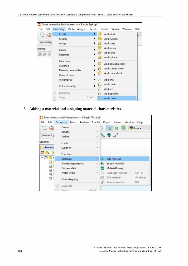
Collaborative BIM-based workflows for a new sustainable compression-only structural block construction system
Erasmus Mundus Joint Master Degree Programme – ERASMUS+
European Master in Building Information Modelling BIM A+ 108
3. Adding a material and assigning material characteristics

Collaborative BIM-based workflows for a new sustainable compression-only structural block construction system
Erasmus Mundus Joint Master Degree Programme – ERASMUS+
European Master in Building Information Modelling BIM A+ 109
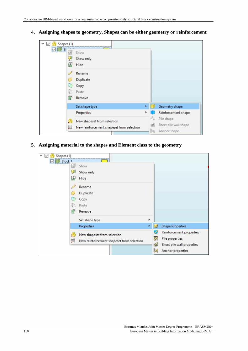
Collaborative BIM-based workflows for a new sustainable compression-only structural block construction system
Erasmus Mundus Joint Master Degree Programme – ERASMUS+
European Master in Building Information Modelling BIM A+ 110
4. Assigning shapes to geometry. Shapes can be either geometry or reinforcement
5. Assigning material to the shapes and Element class to the geometry

Collaborative BIM-based workflows for a new sustainable compression-only structural block construction system
Erasmus Mundus Joint Master Degree Programme – ERASMUS+
European Master in Building Information Modelling BIM A+ 111
6. Adding loads to the shapes
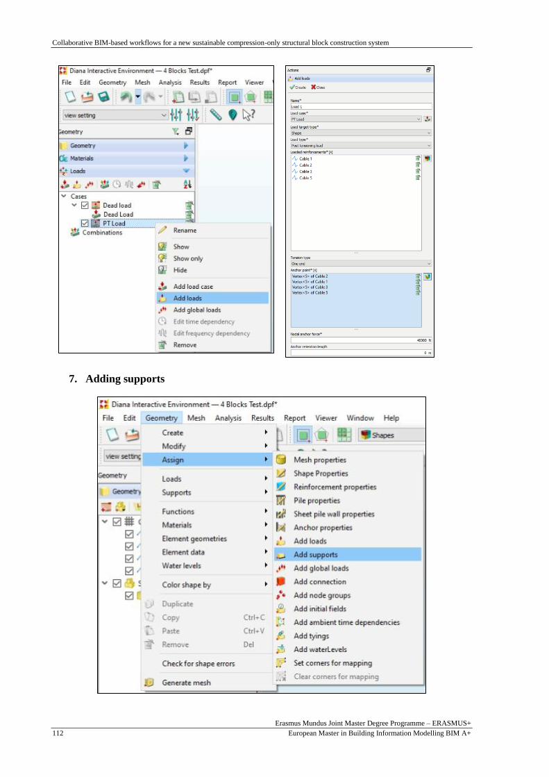
Collaborative BIM-based workflows for a new sustainable compression-only structural block construction system
Erasmus Mundus Joint Master Degree Programme – ERASMUS+
European Master in Building Information Modelling BIM A+ 112
7. Adding supports

Collaborative BIM-based workflows for a new sustainable compression-only structural block construction system
Erasmus Mundus Joint Master Degree Programme – ERASMUS+
European Master in Building Information Modelling BIM A+ 113
8. Adding analysis
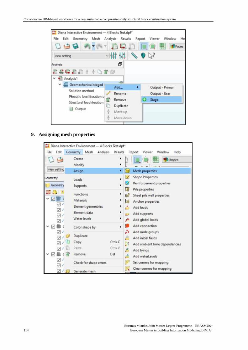
Collaborative BIM-based workflows for a new sustainable compression-only structural block construction system
Erasmus Mundus Joint Master Degree Programme – ERASMUS+
European Master in Building Information Modelling BIM A+ 114
9. Assigning mesh properties

Collaborative BIM-based workflows for a new sustainable compression-only structural block construction system
Erasmus Mundus Joint Master Degree Programme – ERASMUS+
European Master in Building Information Modelling BIM A+ 115
The PT load, assigned to the post tensioning cables, is to be added to each analysis stage after generating
the mesh.

Collaborative BIM-based workflows for a new sustainable compression-only structural block construction system
Erasmus Mundus Joint Master Degree Programme – ERASMUS+
European Master in Building Information Modelling BIM A+ 116
APPENDIX 3: PART GRASSHOPPER CODE FOR FORM-
FINDING AND SHAPE GENERATION
Cable lines generation procedure

Collaborative BIM-based workflows for a new sustainable compression-only structural block construction system
Erasmus Mundus Joint Master Degree Programme – ERASMUS+
European Master in Building Information Modelling BIM A+ 117

Collaborative BIM-based workflows for a new sustainable compression-only structural block construction system
Erasmus Mundus Joint Master Degree Programme – ERASMUS+
European Master in Building Information Modelling BIM A+ 118
