colias: an autonomous micro-robot for robotic swarm applications
TRANSCRIPT
Colias: An Autonomous Micro-robotfor Robotic Swarm Applications
Farshad Arvin, John C. Murray, Chun Zhang and Shigang Yue�
Abstract Robotic swarms that take inspiration fromnature are becoming a fascinating topic for multi-robotresearchers. The aim is to control a large number of simplerobots in order to solve common complex tasks. Due tothe hardware complexities and cost of robot platforms,current research in swarm robotics is mostly performedby simulation software. The simulation of large numbersof these robots in robotic swarm applications is extremelycomplex and often inaccurate due to the poor modelling ofexternal conditions. In this paper, we present the designof a low-cost, open-platform, autonomous micro-robot(Colias) for robotic swarm applications. Colias employsa circular platform with a diameter of 4 cm. It hasa maximum speed of 35 cm/s which enables it to beused in swarm scenarios very quickly over large arenas.Long-range infrared modules with an adjustable outputpower allow the robot to communicate with its directneighbours at a range of 0.5 cm to 2 m. Colias has beendesigned as a complete platform with supporting softwaredevelopment tools for robotics education and research. Ithas been tested in both individual and swarm scenarios,and the observed results demonstrate its feasibility for useas a micro-sized mobile robot and as a low-cost platformfor robot swarm applications.
Keywords Autonomous Robot, Swarm Robotics,Collective Behaviour, Micro-robot
1. Introduction
Autonomous robot swarms [1] represent a fascinating,bio-inspired concept which provides a robust and flexiblerobotics system by exploiting large numbers of robots.This concept allows for the coordination of simplephysical robots in order to cooperatively perform tasks.The decentralized control of robotic swarms can beachieved by providing well-defined interaction rulesfor each individual robot. These rules are executedcontinuously in an infinite loop and can provide forsuitable collective behaviours in robotic environments[2]. Biological self-organization behaviours provide someof the best examples in setting up a robotic swarmsystem [3]. The collective behaviour in a group of robotsemerges from interactions between simple agents, and sohas an indirect relationship with the behaviour of eachindividual robot. A simple modification of an individualrobot’s behaviour could result in a significant changein the collective behaviour of the swarm. Therefore, thehomogeneity of the robot platform is an important issuein executing robotic swarm scenarios. The platform mustbe able to imitate swarm behaviours found in nature, suchas insects, birds and fish. It should be designed withcompact physical dimensions to allow for the study oflarge- scale swarm behaviour in the lab area. A practicalmechatronics design is required to simplify replication andensure platform homogeneity, as in the standard definitionof a robotic swarm system [4].
Farshad Arvin, John Murray, Chun Zhang and Shigang Yue: Colias: An Autonomous Micro Robot for Swarm Robotic Applications
1
ARTICLE
Int J Adv Robot Syst, 2014, 11:113 | doi: 10.5772/58730
1 School of Computer Science, University of Lincoln, Lincoln, UK2 Institute of Microelectronics, Tsinghua University, Beijing, China* Corresponding author E-mail: [email protected]
Received 10 Nov 2013; Accepted 31 May 2014
DOI: 10.5772/58730
∂ 2014 The Author(s). Licensee InTech. This is an open access article distributed under the terms of the CreativeCommons Attribution License (http://creativecommons.org/licenses/by/3.0), which permits unrestricted use,distribution, and reproduction in any medium, provided the original work is properly cited.
Farshad Arvin1, John Murray1, Chun Zhang2 and Shigang Yue1,*
Colias: An Autonomous Micro Robot for Swarm Robotic ApplicationsRegular Paper
International Journal of Advanced Robotic Systems
Robot Cost Sensor Motion/Speed Size AutonomyColias £25 distance, light, bump, bearing, range wheel, 35 cm/s 4 cm 1-3 hAMiR [5] £65 distance, light, bearing wheel, 10 cm/s 6.5 cm 2 hAlice [6] N/A distance, camera wheel, 4 cm/s 2.2 10 hJasmine [7] £80 distance, light, bearing wheel , N/A 3 cm 1-2 hE-puck [8] £580 distance, camera, bearing, accele, mic wheel, 13 cm/s 7.5 cm 1-10 hKobot [9] £800 distance, bearing, vision, compass wheel , N/A 12 cm 10 hKilobot [10] £75 distance, light vibration, 1 cm/s 3.3 cm 3-24 hR-one [11] £220 light, IR, gyro, bump, accelerometer wheel, 30 cm/s 10 cm 6 hSwarmBot [12] N/A range, bearing, camera, bump wheel, 50 cm/s 12.7 cm 3 h
Table 1. Comparison of some swarm robotics platforms
Several mobile robot platforms have previously beendeveloped in studying swarm applications - these areshown in Table 1. Alice [6] is one such swarm robot builtwith a very small package size; it has been employedin various swarm research applications, such as theembodiment of cockroach aggregation [13]. The latestversion of Alice is equipped with proximity sensors andinfrared (IR) remote receivers. It can communicate with itsdirect neighbour using the IR sensors at short distances.The commercialized Alice was previously around a fewhundred pounds. Another micro-robot which has beenwidely used in swarm robotics is Jasmine [7]. This robotuses six IR sensors to detect obstacles as well as robots inclose proximity. Jasmine has played the role of a honeybeein several aggregation (BEECLUST) scenarios [14, 15].E-puck [8] is one of the most successful robots, beingmainly designed for education in the engineering field,and it is equipped with several sensors. However, thecommercialized version of the basic e-puck is about £580and an extra £300 is needed to obtain an additional rangeand bearing module [16]. Kilobot [10] is also a robot swarmplatform with scalable functions, such as a group chargerand programmer. It uses a slip-stick principle for motionwhich reduces its cost, since the robot does not use motorsor wheels. However, the motion method has severaldrawbacks, such as that the achieved speed is low, whichlimits its application in swarm scenarios. Its method ofmotion reduces its use on various surfaces. We previouslydeveloped AMiR (Autonomous Miniature Robot) [5] as alow-cost open-hardware platform for swarm applications.It uses IR sensors for distance estimation and short-rangecommunication. Several research applications have beenperformed with AMiR, including BEECLUST aggregation[17] and the extended version of BEECLUST [18–20].Moreover, AMiR is simulated in Player/Stage and wasused as the simulated robot swarm platform in [21].Although the feasibility of AMiR for use in swarm roboticshas been demonstrated, its motion is relatively slow and itssize does not allow for the use of a large number of robotsin a small arena. The limited range of communication isanother disadvantage of AMiR which limits the scenariosto short-range coherent behaviours.
The simulation of large numbers of such robots isextremely complex and the results often do not meetthe observed results of what would be exhibited in realrobot experiments. Therefore, to imitate the bio-inspiredmechanisms of swarm robots and to enable all researchgroups even with limited funding to perform suchresearch with real robots, the robot platform must have thefollowing criteria: low-cost design, long-term autonomy,
long-range communication, bearing, distance and obstacledetection, neighbouring robot detection, fast motion, asmall size and an open-source design.
We have developed a new platform to meet theserequirements. The design of Colias was considered interms of these requirements and, due to its small sizeand fast motion, experiments could be conducted bothcost- and time-effectively in a small working area. Incomparison to the other mobile robots which are utilizedin swarm robotic research, Colias is a low-cost platform(about £25) and hence it is feasible for the easy andeconomic replication of large numbers of robots.
The rest of this paper is organized as follows. In Section 2,we introduce the hardware of the robot. Following that, inSection 3, we explain a swarm algorithm implemented byColias. In Section 4, we discuss the experimental resultsof individual and social experiments. Finally, in Section5, we draw conclusions and discuss the future researchdirections in which the robot might be involved.
2. Colias Design
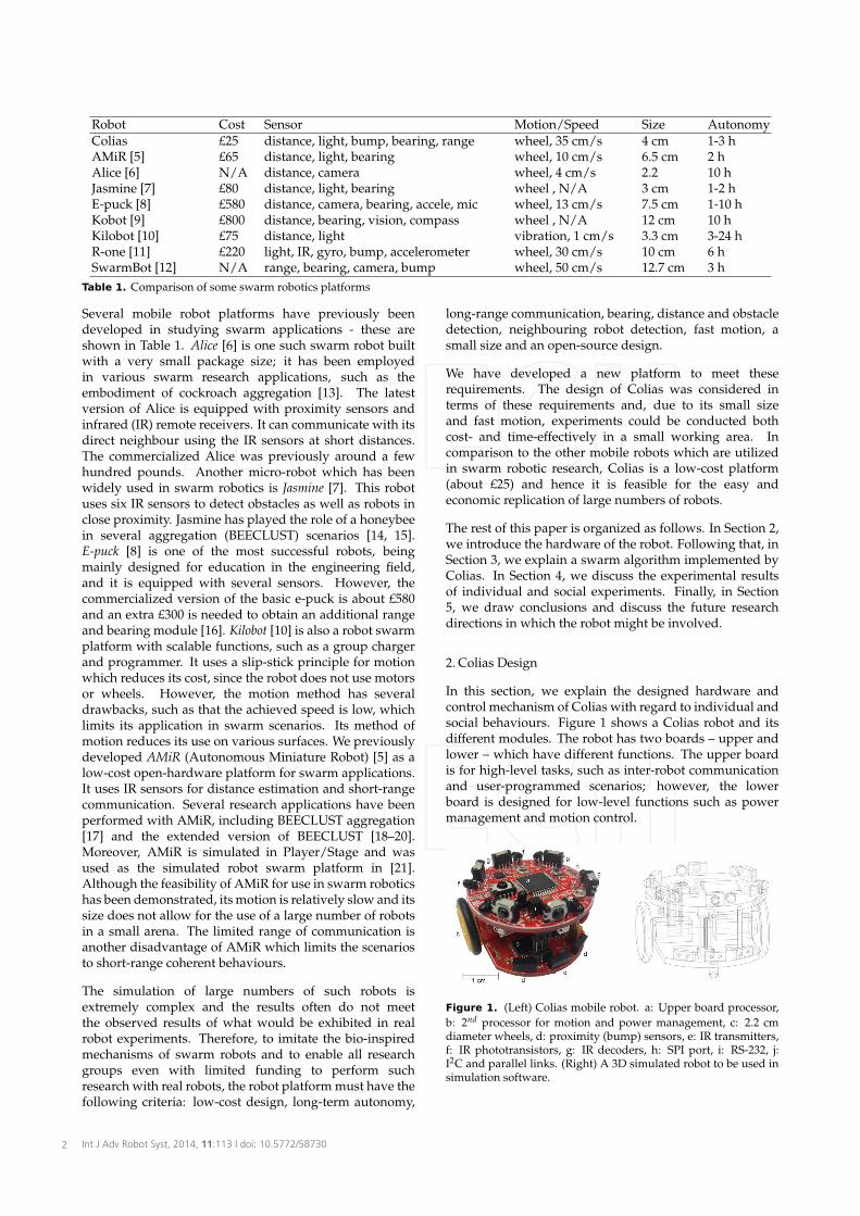
In this section, we explain the designed hardware andcontrol mechanism of Colias with regard to individual andsocial behaviours. Figure 1 shows a Colias robot and itsdifferent modules. The robot has two boards – upper andlower – which have different functions. The upper boardis for high-level tasks, such as inter-robot communicationand user-programmed scenarios; however, the lowerboard is designed for low-level functions such as powermanagement and motion control.
Figure 1. (Left) Colias mobile robot. a: Upper board processor,b: 2nd processor for motion and power management, c: 2.2 cmdiameter wheels, d: proximity (bump) sensors, e: IR transmitters,f: IR phototransistors, g: IR decoders, h: SPI port, i: RS-232, j:I2C and parallel links. (Right) A 3D simulated robot to be used insimulation software.
Int J Adv Robot Syst, 2014, 11:113 | doi: 10.5772/587302
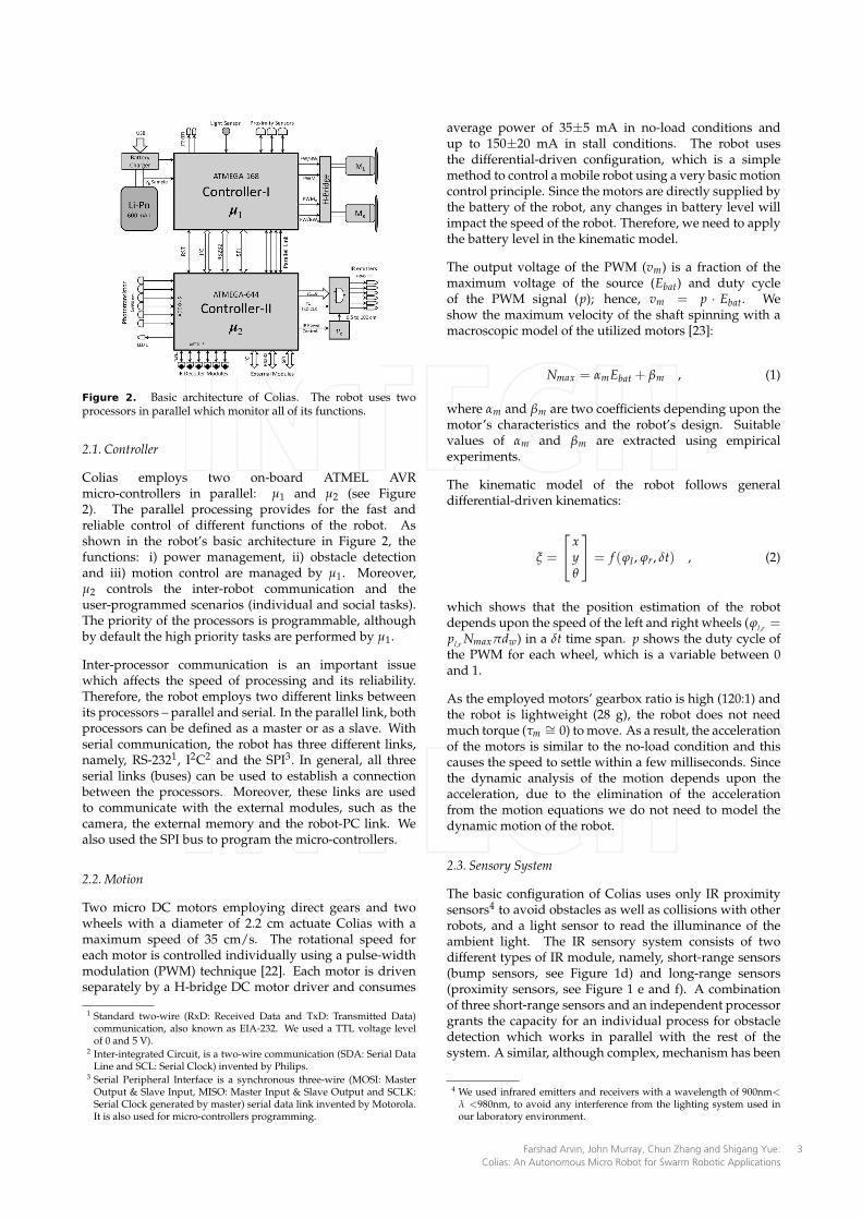
Figure 2. Basic architecture of Colias. The robot uses twoprocessors in parallel which monitor all of its functions.
2.1. Controller
Colias employs two on-board ATMEL AVRmicro-controllers in parallel: µ1 and µ2 (see Figure2). The parallel processing provides for the fast andreliable control of different functions of the robot. Asshown in the robot’s basic architecture in Figure 2, thefunctions: i) power management, ii) obstacle detectionand iii) motion control are managed by µ1. Moreover,µ2 controls the inter-robot communication and theuser-programmed scenarios (individual and social tasks).The priority of the processors is programmable, althoughby default the high priority tasks are performed by µ1.
Inter-processor communication is an important issuewhich affects the speed of processing and its reliability.Therefore, the robot employs two different links betweenits processors – parallel and serial. In the parallel link, bothprocessors can be defined as a master or as a slave. Withserial communication, the robot has three different links,namely, RS-2321, I2C2 and the SPI3. In general, all threeserial links (buses) can be used to establish a connectionbetween the processors. Moreover, these links are usedto communicate with the external modules, such as thecamera, the external memory and the robot-PC link. Wealso used the SPI bus to program the micro-controllers.
2.2. Motion
Two micro DC motors employing direct gears and twowheels with a diameter of 2.2 cm actuate Colias with amaximum speed of 35 cm/s. The rotational speed foreach motor is controlled individually using a pulse-widthmodulation (PWM) technique [22]. Each motor is drivenseparately by a H-bridge DC motor driver and consumes
1 Standard two-wire (RxD: Received Data and TxD: Transmitted Data)communication, also known as EIA-232. We used a TTL voltage levelof 0 and 5 V).
2 Inter-integrated Circuit, is a two-wire communication (SDA: Serial DataLine and SCL: Serial Clock) invented by Philips.
3 Serial Peripheral Interface is a synchronous three-wire (MOSI: MasterOutput & Slave Input, MISO: Master Input & Slave Output and SCLK:Serial Clock generated by master) serial data link invented by Motorola.It is also used for micro-controllers programming.
average power of 35±5 mA in no-load conditions andup to 150±20 mA in stall conditions. The robot usesthe differential-driven configuration, which is a simplemethod to control a mobile robot using a very basic motioncontrol principle. Since the motors are directly supplied bythe battery of the robot, any changes in battery level willimpact the speed of the robot. Therefore, we need to applythe battery level in the kinematic model.
The output voltage of the PWM (vm) is a fraction of themaximum voltage of the source (Ebat) and duty cycleof the PWM signal (p); hence, vm = p · Ebat. Weshow the maximum velocity of the shaft spinning with amacroscopic model of the utilized motors [23]:
Nmax = αmEbat + βm , (1)
where αm and βm are two coefficients depending upon themotor’s characteristics and the robot’s design. Suitablevalues of αm and βm are extracted using empiricalexperiments.
The kinematic model of the robot follows generaldifferential-driven kinematics:
ξ =
xyθ
= f (ϕl , ϕr, δt) , (2)
which shows that the position estimation of the robotdepends upon the speed of the left and right wheels (ϕl,r =pl,r Nmaxπdw) in a δt time span. p shows the duty cycle ofthe PWM for each wheel, which is a variable between 0and 1.
As the employed motors’ gearbox ratio is high (120:1) andthe robot is lightweight (28 g), the robot does not needmuch torque (τm ∼= 0) to move. As a result, the accelerationof the motors is similar to the no-load condition and thiscauses the speed to settle within a few milliseconds. Sincethe dynamic analysis of the motion depends upon theacceleration, due to the elimination of the accelerationfrom the motion equations we do not need to model thedynamic motion of the robot.
2.3. Sensory System
The basic configuration of Colias uses only IR proximitysensors4 to avoid obstacles as well as collisions with otherrobots, and a light sensor to read the illuminance of theambient light. The IR sensory system consists of twodifferent types of IR module, namely, short-range sensors(bump sensors, see Figure 1d) and long-range sensors(proximity sensors, see Figure 1 e and f). A combinationof three short-range sensors and an independent processorgrants the capacity for an individual process for obstacledetection which works in parallel with the rest of thesystem. A similar, although complex, mechanism has been
4 We used infrared emitters and receivers with a wavelength of 900nm<λ <980nm, to avoid any interference from the lighting system used inour laboratory environment.
Farshad Arvin, John Murray, Chun Zhang and Shigang Yue: Colias: An Autonomous Micro Robot for Swarm Robotic Applications
3

found in locust vision, in which a specific neuron called the’lobula giant movement detector’ (LGMD) which reacts toobjects approaching the insect’s eyes [24].
The long-range system is composed of six IR proximitysensors (each 60◦ on the robot’s upper board) for obstacleand robot detection [25]. The IR sensing system is ableto distinguish robots from obstacles. The range of thesystem is approximately 15±1 cm with a radiant powerof 6 mW/sr (adjustable up to 15 mW/sr).
Obstacle detection and distance estimation use thefundamental principles of electromagnetic radiation andits reflections. The reflected IR value that is measuredby a sensor is mathematically modelled by the followingequation [26]:
s(x, θ) =αc cos θ
x2 + βc , (3)
where s(x, θ) is the output value of the sensor, x is thedistance of the obstacle, and θ is the angle of incidencewith the surface. The model variable αc includes severalparameters, such as the reflectivity coefficient, the outputpower of the emitted IR and the sensitivity of the sensor.βc is the offset value of the amplifier and ambient lighteffect. White body and black body surfaces reflect andabsorb IR radiations with different ratios, which is asignificant issue in selecting between obstacles and wallsfor robotic environments. The model parameters (αc andβc) are estimated empirically and are applied to futurecalculations.
In addition, the light sensor is placed at the bottom of therobot and is directly connected to both processors – µ1and µ2. Therefore, each controller is able to translate theilluminance of the ambient light from an analogue valueto a digital number between 0 and 255. In robot swarmscenarios, light is mostly used as a cue in the group-leveltask, such as with the aggregation of honeybees [14, 18].
Furthermore, the serial communication links (explained inthe controller section) allow the robot to utilize an extrasensory system, such as camera or ultrasonic modules.
2.4. Inter-robot Communication
In multi-robot experiments, the robots need to utilize acommunication media in order to share their informationand make collective decisions. Wireless communicationis generally used when a scenario is to be accomplishedwith mobile robots. In this regard, infrared is a suitablechoice as an inter-robot communication medium forrobotic swarm applications compared with other wirelesscommunication techniques, such as radio frequency. Theadvantages of using IR in swarm applications includeposition estimation, neighbouring robot recognition anddirect communication, and they can be utilized for obstacleavoidance [25].
Colias translates its IR receivers’ values to estimate thedistance and bearing of neighbouring robots. The distanceof a neighbour can be simply judged by the amplitude ofthe received IR. Since the robot’s receivers are placed apartsymmetrically (60◦), we can estimate the relative angular
Figure 3. Amplitude-shift keying modulation for messagetransmission with (a) on/off and (b) pulse/off signals
position of the neighbouring robot using the followingequation:
φ = atan
(∑6
i=1 si sin(γi)
∑6i=1 si cos(γi)
), (4)
where φ is the estimated angular position of the neighbour,γi is the angular distance between the ith sensor and therobot’s head, and si, i ∈ {1, 2, 3, 4, 5, 6} is the translated IRintensity from sensor i.
The robot’s message must be modulated and transmittedto its direct neighbours. There are several modulationtechniques for data transmission. In general, two typesof modulation methods are employed in short-rangecommunication, which are: i) amplitude-shift keying(on/off mode), and ii) a mix of pulse and amplitude-shiftkeying. Figure 3 reveals the modulation methods whichcan be performed by Colias’s communication module. Asshown in the diagram, a TxD clock must be connectedto a pulse generator with a frequency of ft (for pulse/offmodulation) or logic ’1’ (for on/off modulation). However,the TxD clock is fed by a timer of the main processor,and hence it does not need an external clock source.The frequency of modulation, ft, depends upon thereceivers’ sampling rate. In our robot, we use a 38kHz carrier frequency. Moreover, ve adjusts the outputpower (amplitude) of the transmitter, which controls themaximum distance of communication.
Each message is formatted to 10 bits length, starting witha one bit preamble of logic ’1’. The next eight bits are theactual message body [27]. The last bit is reserved for futurecommunication methods between different robots in thecase of heterogeneous scenarios. Since the communicationmessages are too short (10 bits), the robot uses a low datarate of 200 bps (20 messages/sec) for communication inorder to increase the reliability of the communication andreduce the error rate.
2.5. Power Management
In swarm robot scenarios, the robot must have sufficientbattery power to complete a given task. To achievelong-term autonomy, we need to have a proper powermanagement system to monitor all the functions of therobot during a task and to control the battery chargingcurrent during a recharging process such that it increasesthe battery life. In Colias, the lower board is responsible formanaging power consumption as well as the rechargingprocess. The power consumption of the robot with normal
Int J Adv Robot Syst, 2014, 11:113 | doi: 10.5772/587304
motion (in a quiet arena with only walls) and short-rangecommunication (low-power IR emitter) is around 560 mA.However, it can be reduced to about 200 mA when theemitters are turned on only occasionally and the robotmoves at a faster speed. A 3.7 V, 600 mAh (extendibleup to 1200 mAh) lithium-polymer battery is used as themain power source, which gives autonomy of aroundthree hours for the robot. More battery power is used byIR emitters and decoders when the emitter is turned oncontinuously. Therefore, the power consumption can bereduced to at least 50% by using pulse modulation in theIR emitters as well as a short data-packet size.
The recharging process of the battery is monitored by anexternal constant current/constant voltage linear chargerIC (LTC4054-4.2). We fixed the charging current to amaximum of 400 mA in order to be able to use USB powerto charge the battery.
Moreover, in-scenario recharging techniques, such as adocking charger [28–30] or movable chargers [31], canbe applied to increase the autonomy time in long-termscenarios.
2.6. Firmware and Programming
In order to provide for simple programming anduser-friendly robotic implementation, we provide variousbasic and high-level functions. The utilized swarmbehaviours use sensors and received communicationvalues to make a decision. Decisions are made in twodifferent forms which are in programming routines, suchas calling a function, and hardware modules, such ascontrolling motors or transmitting messages.
Microcontroller-based systems are flexible enough to usevarious programming languages and compilers. Thereare several types of compilers for AVR microcontrollers,such as assembly, C, Basic and Pascal. GNU [32] CompilerCollection (GCC) is a compiler of a GNU operating systemthat Colias uses for its programming.
3. Swarm Scenario
We evaluate the feasibility of Colias for use in collectiveswarm scenarios. In this regard, the state-of-the-art swarmaggregation algorithm (BEECLUST) [14] is implementedwith different population sizes. Figure 4 reveals thebehaviour of the each robot during the BEECLUSTscenario. As can be seen in the diagram, the robots havea simple algorithm to follow. In general, after detectingan obstacle, a robot rotates and executes an obstacleavoidance routine. Alternatively, if the robot detectsanother robot, it stops and measures the illuminance ofthe ambient light. It is worth mentioning that a neighbourrobot can be detected at a distance of 2 cm, which is calledan ’inter-robot collision’. After each inter-robot collision,the robot waits. The duration spent waiting depends uponthe measured illuminance. A higher light illuminanceresults in a longer stationary time. When the waiting timeis over, the robot turns by a random degree and movesforward.
Figure 4. Finite state automaton that shows the robots’behaviour using BEECLUST
BEECLUST has been used in numerous swarm researchapplications as a bio-inspired aggregation algorithmwith different configurations using real robots [7] andsimulation software [33]. Mostly, gradient light isemployed as the cue for the aggregation [14, 15, 18]. Inaddition, we previously implemented BEECLUST using asound source as the cue for the aggregation [19, 20].
3.1. Arena Setup
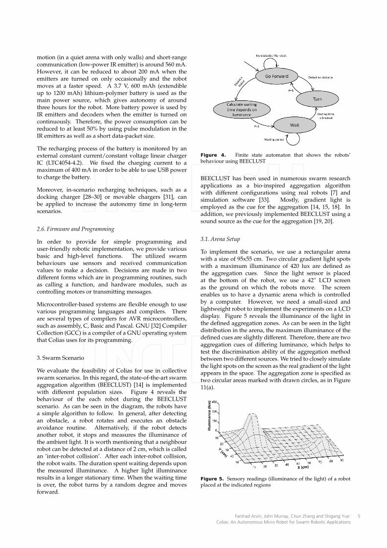
To implement the scenario, we use a rectangular arenawith a size of 95x55 cm. Two circular gradient light spotswith a maximum illuminance of 420 lux are defined asthe aggregation cues. Since the light sensor is placedat the bottom of the robot, we use a 42" LCD screenas the ground on which the robots move. The screenenables us to have a dynamic arena which is controlledby a computer. However, we need a small-sized andlightweight robot to implement the experiments on a LCDdisplay. Figure 5 reveals the illuminance of the light inthe defined aggregation zones. As can be seen in the lightdistribution in the arena, the maximum illuminance of thedefined cues are slightly different. Therefore, there are twoaggregation cues of differing luminance, which helps totest the discrimination ability of the aggregation methodbetween two different sources. We tried to closely simulatethe light spots on the screen as the real gradient of the lightappears in the space. The aggregation zone is specified astwo circular areas marked with drawn circles, as in Figure11(a).
Figure 5. Sensory readings (illuminance of the light) of a robotplaced at the indicated regions
Farshad Arvin, John Murray, Chun Zhang and Shigang Yue: Colias: An Autonomous Micro Robot for Swarm Robotic Applications
5
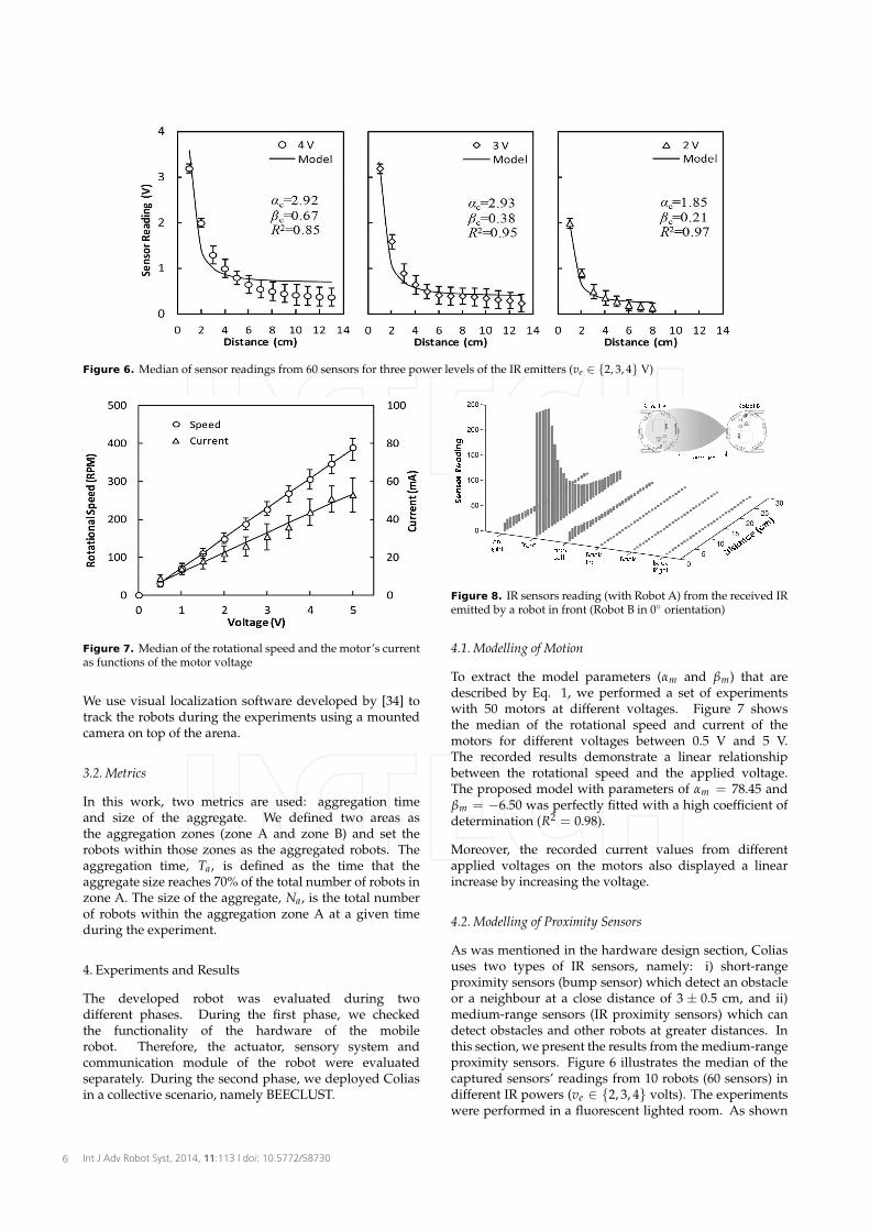
Figure 6. Median of sensor readings from 60 sensors for three power levels of the IR emitters (ve ∈ {2, 3, 4} V)
Figure 7. Median of the rotational speed and the motor’s currentas functions of the motor voltage
We use visual localization software developed by [34] totrack the robots during the experiments using a mountedcamera on top of the arena.
3.2. Metrics
In this work, two metrics are used: aggregation timeand size of the aggregate. We defined two areas asthe aggregation zones (zone A and zone B) and set therobots within those zones as the aggregated robots. Theaggregation time, Ta, is defined as the time that theaggregate size reaches 70% of the total number of robots inzone A. The size of the aggregate, Na, is the total numberof robots within the aggregation zone A at a given timeduring the experiment.
4. Experiments and Results
The developed robot was evaluated during twodifferent phases. During the first phase, we checkedthe functionality of the hardware of the mobilerobot. Therefore, the actuator, sensory system andcommunication module of the robot were evaluatedseparately. During the second phase, we deployed Coliasin a collective scenario, namely BEECLUST.
Figure 8. IR sensors reading (with Robot A) from the received IRemitted by a robot in front (Robot B in 0◦ orientation)
4.1. Modelling of Motion
To extract the model parameters (αm and βm) that aredescribed by Eq. 1, we performed a set of experimentswith 50 motors at different voltages. Figure 7 showsthe median of the rotational speed and current of themotors for different voltages between 0.5 V and 5 V.The recorded results demonstrate a linear relationshipbetween the rotational speed and the applied voltage.The proposed model with parameters of αm = 78.45 andβm = −6.50 was perfectly fitted with a high coefficient ofdetermination (R2 = 0.98).
Moreover, the recorded current values from differentapplied voltages on the motors also displayed a linearincrease by increasing the voltage.
4.2. Modelling of Proximity Sensors
As was mentioned in the hardware design section, Coliasuses two types of IR sensors, namely: i) short-rangeproximity sensors (bump sensor) which detect an obstacleor a neighbour at a close distance of 3 ± 0.5 cm, and ii)medium-range sensors (IR proximity sensors) which candetect obstacles and other robots at greater distances. Inthis section, we present the results from the medium-rangeproximity sensors. Figure 6 illustrates the median of thecaptured sensors’ readings from 10 robots (60 sensors) indifferent IR powers (ve ∈ {2, 3, 4} volts). The experimentswere performed in a fluorescent lighted room. As shown
Int J Adv Robot Syst, 2014, 11:113 | doi: 10.5772/587306
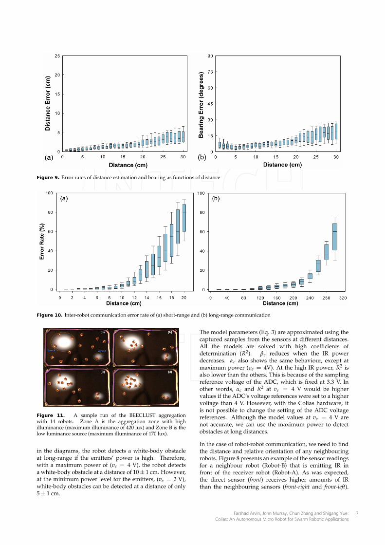
Figure 9. Error rates of distance estimation and bearing as functions of distance
Figure 10. Inter-robot communication error rate of (a) short-range and (b) long-range communication
Figure 11. A sample run of the BEECLUST aggregationwith 14 robots. Zone A is the aggregation zone with highilluminance (maximum illuminance of 420 lux) and Zone B is thelow luminance source (maximum illuminance of 170 lux).
in the diagrams, the robot detects a white-body obstacleat long-range if the emitters’ power is high. Therefore,with a maximum power of (ve = 4 V), the robot detectsa white-body obstacle at a distance of 10± 1 cm. However,at the minimum power level for the emitters, (ve = 2 V),white-body obstacles can be detected at a distance of only5 ± 1 cm.
The model parameters (Eq. 3) are approximated using thecaptured samples from the sensors at different distances.All the models are solved with high coefficients ofdetermination (R2). βc reduces when the IR powerdecreases. αc also shows the same behaviour, except atmaximum power (ve = 4V). At the high IR power, R2 isalso lower than the others. This is because of the samplingreference voltage of the ADC, which is fixed at 3.3 V. Inother words, αc and R2 at ve = 4 V would be highervalues if the ADC’s voltage references were set to a highervoltage than 4 V. However, with the Colias hardware, itis not possible to change the setting of the ADC voltagereferences. Although the model values at ve = 4 V arenot accurate, we can use the maximum power to detectobstacles at long distances.
In the case of robot-robot communication, we need to findthe distance and relative orientation of any neighbouringrobots. Figure 8 presents an example of the sensor readingsfor a neighbour robot (Robot-B) that is emitting IR infront of the receiver robot (Robot-A). As was expected,the direct sensor (front) receives higher amounts of IRthan the neighbouring sensors (front-right and front-left).
Farshad Arvin, John Murray, Chun Zhang and Shigang Yue: Colias: An Autonomous Micro Robot for Swarm Robotic Applications
7
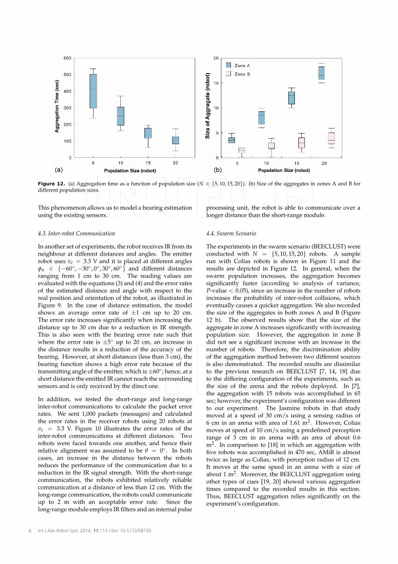
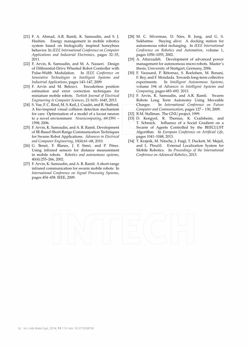
Figure 12. (a) Aggregation time as a function of population size (N ∈ {5, 10, 15, 20}). (b) Size of the aggregates in zones A and B fordifferent population sizes.
This phenomenon allows us to model a bearing estimationusing the existing sensors.
4.3. Inter-robot Communication
In another set of experiments, the robot receives IR from itsneighbour at different distances and angles. The emitterrobot uses ve = 3.3 V and it is placed at different anglesφn ∈ {−60◦,−30◦, 0◦, 30◦, 60◦} and different distancesranging from 1 cm to 30 cm. The reading values areevaluated with the equations (3) and (4) and the error ratesof the estimated distance and angle with respect to thereal position and orientation of the robot, as illustrated inFigure 9. In the case of distance estimation, the modelshows an average error rate of ±1 cm up to 20 cm.The error rate increases significantly when increasing thedistance up to 30 cm due to a reduction in IR strength.This is also seen with the bearing error rate such thatwhere the error rate is ±5◦ up to 20 cm, an increase inthe distance results in a reduction of the accuracy of thebearing. However, at short distances (less than 3 cm), thebearing function shows a high error rate because of thetransmitting angle of the emitter, which is ±60◦; hence, at ashort distance the emitted IR cannot reach the surroundingsensors and is only received by the direct one.
In addition, we tested the short-range and long-rangeinter-robot communications to calculate the packet errorrates. We sent 1,000 packets (messages) and calculatedthe error rates in the receiver robots using 20 robots atve = 3.3 V. Figure 10 illustrates the error rates of theinter-robot communications at different distances. Tworobots were faced towards one another, and hence theirrelative alignment was assumed to be θ = 0◦. In bothcases, an increase in the distance between the robotsreduces the performance of the communication due to areduction in the IR signal strength. With the short-rangecommunication, the robots exhibited relatively reliablecommunication at a distance of less than 12 cm. With thelong-range communication, the robots could communicateup to 2 m with an acceptable error rate. Since thelong-range module employs IR filters and an internal pulse
processing unit, the robot is able to communicate over alonger distance than the short-range module.
4.4. Swarm Scenario
The experiments in the swarm scenario (BEECLUST) wereconducted with N = {5, 10, 15, 20} robots. A samplerun with Colias robots is shown in Figure 11 and theresults are depicted in Figure 12. In general, when theswarm population increases, the aggregation becomessignificantly faster (according to analysis of variance,P-value < 0.05), since an increase in the number of robotsincreases the probability of inter-robot collisions, whicheventually causes a quicker aggregation. We also recordedthe size of the aggregates in both zones A and B (Figure12 b). The observed results show that the size of theaggregate in zone A increases significantly with increasingpopulation size. However, the aggregation in zone Bdid not see a significant increase with an increase in thenumber of robots. Therefore, the discrimination abilityof the aggregation method between two different sourcesis also demonstrated. The recorded results are dissimilarto the previous research on BEECLUST [7, 14, 18] dueto the differing configuration of the experiments, such asthe size of the arena and the robots deployed. In [7],the aggregation with 15 robots was accomplished in 65sec; however, the experiment’s configuration was differentto our experiment. The Jasmine robots in that studymoved at a speed of 30 cm/s using a sensing radius of6 cm in an arena with area of 1.61 m2. However, Coliasmoves at speed of 10 cm/s using a predefined perceptionrange of 3 cm in an arena with an area of about 0.6m2. In comparison to [18] in which an aggregation withfive robots was accomplished in 470 sec, AMiR is almosttwice as large as Colias, with perception radius of 12 cm.It moves at the same speed in an arena with a size ofabout 1 m2. Moreover, the BEECLUST aggregation usingother types of cues [19, 20] showed various aggregationtimes compared to the recorded results in this section.Thus, BEECLUST aggregation relies significantly on theexperiment’s configuration.
Int J Adv Robot Syst, 2014, 11:113 | doi: 10.5772/587308

Based on the observed results of the performedexperiments regarding social and individual behaviours,the feasibility of the developed robot for use in swarmscenarios has been demonstrated. Since the robot isdesigned with a small package size, it would be possibleto use large numbers of the robots in real robot scenarios.
5. Conclusion
The development of a new, low-cost (about £25),open-hardware platform was presented. The preliminaryexperiments were performed on hardware componentssuch as actuators and sensory systems. We modelled themotion and sensory system of the robot mathematicallyand the model parameters were extracted empirically.Therefore, the feasibility of the developed robot as anautonomous platform has been demonstrated. SinceColias is developed for use in swarm robotics research, itplayed a honeybee role in a bio-inspired scenario called’honeybee aggregation’. The results showed that the robotis highly amenable to deployment in collective behaviours.Although the robot has a basic sensory system andsupports inter-robot communication, for some complexscenarios which require higher levels of perception wedecided to add new features to the robot. For ourfuture work, we are working on an extension of thevision module with a fast ARM processor to implementbio-inspired vision mechanisms.
6. Acknowledgement
This work is supported by EU FP7-IRSES project EYE2E(269118), LIVCODE (295151) and HAZCEPT (318907).
7. References
[1] M. Brambilla, E. Ferrante, M. Birattari, andM. Dorigo. Swarm robotics: a review from theswarm engineering perspective. Swarm Intelligence,7(1):1–41, 2013.
[2] D. D. Dudenhoeffer and M. P. Jones. A formationbehavior for large-scale micro-robot forcedeployment. In Simulation Conference Proceedings,volume 1, pages 972–982, 2000.
[3] S. Camazine, N.R. Franks, J. Sneyd, E. Bonabeau, J.-L.Deneubourg, and G. Theraulaz. Self-organization inbiological systems. Princeton University Press, 2003.
[4] E. Sahin. Swarm robotics: From sources of inspirationto domains of application. In Lecture Notes inComputer Science, volume 3342, pages 10–20. Springer,2005.
[5] F. Arvin, K. Samsudin, and A. R. Ramli. Developmentof a Miniature Robot for Swarm Robotic Application.International Journal of Computer and ElectricalEngineering, 1:436–442, 2009.
[6] G. Caprari, T. Estier, and R. Siegwart. Fascination ofdown scaling - alice the sugar cube robot. Journal ofMicro-Mechatronics, 1(3):177–189, 2002.
[7] S. Kernbach, R. Thenius, O. Kernbach, andT. Schmickl. Re-embodiment of Honeybee
Aggregation Behavior in an Artificial Micro-RoboticSystem. Adaptive Behavior, 17(3):237–259, 2009.
[8] F. Mondada, M. Bonani, X. Raemy, J. Pugh, C. Cianci,A. Klaptocz, S. Magnenat, J-C. Zufferey, D. Floreano,and A. Martinoli. The e-puck, a robot designed foreducation in engineering. In Proceedings of the 9thconference on autonomous robot systems and competitions,volume 1, pages 59–65, 2009.
[9] A. E. Turgut, H. Çelikkanat, F. Gökçe, and E. Sahin.Self-organized Flocking in Mobile Robot Swarms.Swarm Intelligence, 2(2):97–120, 2008.
[10] M. Rubenstein, C. Ahler, and R. Nagpal. Kilobot:A low cost scalable robot system for collectivebehaviors. In IEEE International Conference on Roboticsand Automation, pages 3293–3298, 2012.
[11] J. McLurkin, A. J. Lynch, S. Rixner, T.W. Barr, A. Chou,K. Foster, and S. Bilstein. A Low-Cost Multi-robotSystem for Research, Teaching, and Outreach. InDistributed Autonomous Robotic Systems, volume 83,pages 597–609, 2013.
[12] J. McLurkin, J. Smith, J. Frankel, D. Sotkowitz,D. Blau, and B. Schmidt. Speaking swarmish:Human-robot interface design for large swarmsof autonomous mobile robots. In AAAI springsymposium, 2006.
[13] S. Garnier, C. Jost, J. Gautrais, M. Asadpour,G. Caprari, R. Jeanson, A. Grimal, and G. Theraulaz.The embodiment of cockroach aggregationbehavior in a group of micro-robots. ArtificialLife, 14(4):387–408, 2008.
[14] T. Schmickl, R. Thenius, C. Moeslinger, G. Radspieler,S. Kernbach, M. Szymanski, and K. Crailsheim. Getin touch: cooperative decision making based onrobot-to-robot collisions. Autonomous Agents andMulti-Agent Systems, 18(1):133–155, 2009.
[15] M. Bodi, R. Thenius, M. Szopek, T. Schmickl, andK. Crailsheim. Interaction of robot swarms usingthe honeybee-inspired control algorithm BEECLUST.Mathematical and Computer Modelling of DynamicalSystems, 18(1):87–100, 2012.
[16] A. Gutiérrez, A. Campo, M. Dorigo, D. Amor,L. Magdalena, and F. Monasterio-Huelin. Anopen localization and local communication embodiedsensor. Sensors, 8(11):7545–7563, 2008.
[17] F. Arvin, S. Doraisamy, K. Samsudin, F. A. Ahmad,and A. R. Ramli. Implementation of a Cue-BasedAggregation with a Swarm Robotic System. InCommunications in Computer and Information Science,volume 295, pages 113–122. Springer, 2012.
[18] F. Arvin, K. Samsudin, A. R. Ramli, and M. Bekravi.Imitation of Honeybee Aggregation with CollectiveBehavior of Swarm Robots. International Journal ofComputational Intelligence Systems, 4(4):739–748, 2011.
[19] F. Arvin, A. E. Turgut, and S. Yue. Fuzzy-BasedAggregation with a Mobile Robot Swarm. In SwarmIntelligence, volume 7461 of Lecture Notes in ComputerScience, pages 346–347. Springer, 2012.
[20] F. Arvin, A. E. Turgut, F. Bazyari, K. B. Arikan,N. Bellotto, and S. Yue. Cue-based aggregation witha mobile robot swarm: a novel fuzzy-based method.Adaptive Behavior, 22(3):189–206, 2014.
Farshad Arvin, John Murray, Chun Zhang and Shigang Yue: Colias: An Autonomous Micro Robot for Swarm Robotic Applications
9
[21] F. A. Ahmad, A.R. Ramli, K. Samsudin, and S. J.Hashim. Energy management in mobile roboticssystem based on biologically inspired honeybeesbehavior. In IEEE International Conference on ComputerApplications and Industrial Electronics, pages 32–35,2011.
[22] F. Arvin, K. Samsudin, and M. A. Nasseri. Designof Differential-Drive Wheeled Robot Controller withPulse-Width Modulation. In IEEE Conference onInnovative Technologies in Intelligent Systems andIndustrial Applications, pages 143–147, 2009.
[23] F. Arvin and M. Bekravi. Encoderless positionestimation and error correction techniques forminiature mobile robots. Turkish Journal of ElectricalEngineering & Computer Sciences, 21:1631–1645, 2013.
[24] S. Yue, F. C. Rind, M. S. Keil, J. Cuadri, and R. Stafford.A bio-inspired visual collision detection mechanismfor cars: Optimisation of a model of a locust neuronto a novel environment. Neurocomputing, 69:1591 –1598, 2006.
[25] F. Arvin, K. Samsudin, and A. R. Ramli. Developmentof IR-Based Short-Range Communication Techniquesfor Swarm Robot Applications. Advances in Electricaland Computer Engineering, 10(4):61–68, 2010.
[26] G. Benet, F. Blanes, J. E Simó, and P. Pérez.Using infrared sensors for distance measurementin mobile robots. Robotics and autonomous systems,40(4):255–266, 2002.
[27] F. Arvin, K. Samsudin, and A. R. Ramli. A short-rangeinfrared communication for swarm mobile robots. InInternational Conference on Signal Processing Systems,pages 454–458. IEEE, 2009.
[28] M. C. Silverman, D. Nies, B. Jung, and G. S.Sukhatme. Staying alive: A docking station forautonomous robot recharging. In IEEE InternationalConference on Robotics and Automation, volume 1,pages 1050–1055, 2002.
[29] A. Attarzadeh. Development of advanced powermanagement for autonomous micro-robots. Master’sthesis, University of Stuttgart, Germany, 2006.
[30] F. Vaussard, P. Rétornaz, S. Roelofsen, M. Bonani,F. Rey, and F. Mondada. Towards long-term collectiveexperiments. In Intelligent Autonomous Systems,volume 194 of Advances in Intelligent Systems andComputing, pages 683–692. 2013.
[31] F. Arvin, K. Samsudin, and A.R. Ramli. SwarmRobots Long Term Autonomy Using MoveableCharger. In International Conference on FutureComputer and Communication, pages 127 – 130, 2009.
[32] R.M. Stallman. The GNU project, 1999.[33] D. Kengyel, R. Thenius, K. Crailsheim, and
T. Schmick. Influence of a Social Gradient on aSwarm of Agents Controlled by the BEECLUSTAlgorithm. In European Conference on Artificial Life,pages 1041–1048, 2013.
[34] T. Krajník, M. Nitsche, J. Faigl, T. Duckett, M. Mejail,and L. Preucil. External Localization System forMobile Robotics. In Proceedings of the InternationalConference on Advanced Robotics, 2013.
Int J Adv Robot Syst, 2014, 11:113 | doi: 10.5772/5873010