cold lap formation in gas metal arc welding of steel648916/fulltext01.pdf · phd thesis production...
TRANSCRIPT

PhD ThesisProduction Technology2013 No.2
Cold lap formation in Gas Metal Arc Welding of steel
peigang li
An experimental study of micro-lack of fusion defects
III
Acknowledgements
In my studies I have had a lot of help from many people. First of all, I would like to express my deep gratitude to my main supervisor Professor Lars-Erik Svensson for his patience, discussions, suggestions, and help. I also would like to give my sincere thanks to my ex-main supervisor Professor Per Nylén for his valuable encouragement. My sincere thanks are due to my assistant supervisor Nicolaie Markocsan for his positive advice and frank discussion. Special thanks to Professor Leif Karlsson for all he has done. Special thanks to Professor Uta Klement for her efforts in my study.
My heartfelt thanks go to Professor Bill Lucas, Professor Yoshinori Hirata, and Dr. Stephan Egerland for their valuable comments, helpful discussions and faithful advice during the IIW conference and events. Many people have given me support and deserve my thanks: my ex-supervisor Dr. Niklas Järvstråt, Associate Professor Håkan Wirdlius, Dr. Anna Runnemalm, Professor Jack Samuelsson, Dr. Zuheir Barsoum, Dr. Bertil Jonsson, Dr. Anna Ericson Öberg, Mr. Hasse Olsson, Mr. Joakim Hedegård. I thank all my colleagues who helped to create an inspiring and more interesting working environment. Without the financial support from the LOST and WIQ projects, this work would not have been possible. Also, I would like to thank Volvo Construction Equipment (VCE) for important support.
Finally, I would like to dedicate all of my love and this work to Xiaolin and Alex. You mean the world to me!
Peigang Li
12th of July 2013


V
Sammanfattning
Cold laps är små bindfelslikande defekter, huvudsakligen parallella med plåtytan, som kan förekomma vid övergången mellan svets och grundmaterial. De har visat sig initieria utmattning och kan därmed påverka livslängden negativt. Tidigare studier tyder på att det inte helt går att förhindra bildandet vid gas-metallbågsvetsning (MIG/MAG). En bättre förståelse av bildningsmekanismer krävs därför för att minimera förekomsten och inverkan av cold laps.
Målsättningen med arbetet har varit att öka kunskapen om cold laps genom typindelning, karakterisering och identifiering av faktorer som påverkar bildandet. Tandem MIG/MAG svetsning användes för att ta fram svetsar under väl kontrollerade förhållanden. Cold laps identifierades därefter med metallografiska metoder och undersöktes med ljusoptisk mikroskopi, svepelektronmikroskopi och mikroanalys.
Ett nytt sätt att klassificera cold laps introducerades. Tre typer identifierades och namngavs utifrån förmodade bildningsmekanismer: sprutinducerade cold laps, kallflytnings-cold laps och sprut-kallflytnings-cold laps. Cold laps var helt eller delvis fyllda med oxider. De mest frekventa var mangan- och kisel-oxider som tros bildas genom oxidering av smält tillsatsmaterial under droppövergången. Mängden oxider påverkade markant bildandet av cold laps. Svetsning i en icke-oxiderande atmosfär minskade djupet hos speciellt kallflytnings-cold laps. Vid svetsning på en blästrad plåtyta ökade antalet cold laps eftersom luft tenderade att “stängas in” i ojämnheter. Temperaturen hos droppar och grundmaterialet visade sig ha stor betydelse för bildandet av cold laps. Antalet kallflytnings-cold laps minskade tydligt med ökad förvärmning av grundmaterialet.
Mekanismer för bildandet av kallflytnings-cold laps diskuterades utifrån en omfattande literaturstudie. Ett antal samverkande fenomen tros kunna bidra till en lokal kallflytning som Rayleigh instabilitet, balansen mellan olika krafter som påverkar smältan, riktningen hos rörelsemängden som överförs till smältan av droppar som träffar ytan och ett utåtriktat flöde i smältan inducerat av Marangoni-effekten.
Resultaten tyder på att bildandet av cold laps kan begränsas genom att se till svetsprocessen (bågen) är så stabil som möjligt och genom att svetsa på en förvärmt arbetsstycke i en icke-oxiderande atmosfär.


VII
Abstract
Title: Cold lap formation in Gas Metal Arc Welding of steel � An experimental study of micro-lack of fusion defects
Language: English Keywords: Tandem GMAW; Cold laps; Lack of fusion; Spatter; Overlap;
Overflow; Manganese; Silicon; Oxides; Temperature. ISBN: 978-91-977943-5-0
Cold laps are defined as micro-lack of fusion defects at the weld toe more or less parallel to the surface of the parent plate. These defects are known to negatively influence the fatigue properties of weldments. Previous studies suggest that cold lap formation can not be avoided completely in Gas Metal Arc Welding (GMAW). Therefore, a better understanding of formation mechanisms is imperative to be able to minimize the number and size of these defects.
The main objective of this work has been to provide a more comprehensive understanding of cold laps, including categorising, characterisation and defining the most significant factors for formation. GMAW was used to produce welds that were investigated by metallographic methods using light optical microscopy, scanning electron microscopy and energy dispersive spectrometry.
A novel classification of cold laps was introduced and three types of cold laps were identified: spatter cold laps, overlap cold laps and spatter-overlap cold laps. It was shown that cold laps are partially or fully filled by oxides. The most common oxides are manganese silicon oxides which were concluded to be formed primarily by oxidation of droplets. The presence of oxides was found to significantly increase the tendency to form spatter cold laps as well as overlap cold laps. Particularly for overlap cold laps, it was found that the depth (in transverse direction of weld) is reduced when welding in a non-oxidising environment. Welding on blasted surfaces increased the cold lap formation by entrapment of gas. The droplet and base metal temperatures were also found to be significant factors in cold lap formation. For overlap cold laps the occurrence frequency decreased with increased preheating temperature of the base metal.
Mechanisms of overflowing resulting in overlap cold laps were discussed based on an extensive literature review. Several phenomena are believed to contribute to overflow including Rayleigh instability, the balance of forces, transfer of lateral momentum by droplets and an outward Marangoni fluid flow of the weld pool.
The present studies suggest that cold lap formation can be suppressed by ensuring that the welding process (arc) is as stable as possible and by welding on a preheated work piece in a non-oxidising environment.
(Print), 978-91-977943-6-7 (E-version)


IX
Appended Publications
The present thesis is based on the following papers, and the contributions of each paper are, as follows:
Paper I. Characterization of cold lap defects in tandem arc MAG welding
Welding in the world, 2012. 56(September-October (9-10)): p. 20-25 – Authors: Li, P., Svensson, L.-E., Nylén, P., Markocsan, N., Klement, U.,
Li, P. initiated the paper, conducted the experiments and analysis and wrote the paper. Li, P. and ESAB performed the welding experiments. Svensson, L.-E. , Nylén, P., Markocsan, N. and Klement, U. reviewed and ensured the quality of the paper.
Paper II. Influence of oxides on cold lap formation in tandem GMAW
Science and Technology of Welding & Joining, 2012. 17(Number 8): p. 643-648 – Authors: Li, P., Svensson, L.-E., Markocsan, N.,
Li, P. initiated the paper, conducted the experiments and analysis and wrote the paper. Li, P. and Fredrik Tuvsson performed the welding experiments. Svensson, L.-E. and Markocsan, N. reviewed and ensured the quality of the paper.
Paper III. Factors influencing fusion of spatter to the base metal during tandem GMAW welding
Presented at “5th International Swedish Production Symposium” in Linköping, Sweden Nov. 2012 – Authors: Li, P., Svensson, L.-E., Markocsan, N.,
Li, P. initiated the paper, conducted the experiments and analysis and wrote the paper. Li, P. and Fredrik Tuvsson performed the welding experiments. Svensson, L.-E. and Markocsan, N. reviewed and ensured the quality of the paper.
Paper IV. Study on temperature influence on lack of fusion formation in spatter/base metal interface
Presented at “International Conference on Frontiers of Mechanical Engineering, Materials and Energy 2012 (ICFMEME 2012)” in Beijing, China Dec. 2012 – Authors: Li, P., Svensson, L.-E., Markocsan, N.,

X
Li, P. initiated the paper, conducted the experiments and analysis and wrote the paper. Hurtig, K. performed the welding experiment. Svensson, L.-E. and Markocsan, N. reviewed and ensured the quality of the paper.
Paper V. Influence of preheating temperature on cold lap formation in tandem GMAW
Presented at “International Conference on Joining Materials-In Association with the IIW2013” in Helsingør, Denmark May 2013 – Authors: Li, P., Svensson, L.-E., Markocsan, N.,
Li, P. initiated the paper, conducted the experiments and analysis and wrote the paper. Hurtig, K. performed the welding experiment. Svensson, L.-E. and Markocsan, N. reviewed and ensured the quality of the paper.
Paper VI. Cold laps – micro-lack of fusion defects in steel arc welding � A review
In manuscript.
Li, P. initiated the paper, conducted the literature review and wrote the paper. Svensson, L.-E., Markocsan, N., and Karlsson, L., reviewed and ensured the quality of the paper

XI
Table of Contents
Acknowledgements.......................................................................... III Sammanfattning............................................................................... V
Abstract……… ............................................................................... VII Appended Publications ................................................................... IX
Table of Contents ........................................................................... XI
1 Introduction .................................................................... 1
1.1 Background ................................................................ 1
1.2 Objectives and limitations ........................................... 2
2 Gas Metal Arc Welding .................................................. 5
2.1 The GMAW process ................................................... 5
2.2 Arc temperature .......................................................... 9
2.3 Arc pressure ............................................................. 10
2.4 Weld pool convection ............................................... 12
3 Cold laps ....................................................................... 15
3.1 Historical perspective ............................................... 15
3.2 Types of cold laps ..................................................... 17
3.3 Detection of cold laps ............................................... 17
3.4 Factors influencing cold lap formation ...................... 18
4 Oxide formation ............................................................ 27
4.1 Metallurgy of manganese ......................................... 27
4.2 Metallurgy of silicon .................................................. 28
4.3 Oxidation of manganese and silicon ......................... 28
5 Experimental procedures and materials .................... 31
5.1 Base metal and welding consumables ..................... 31
5.2 Shielding gases ........................................................ 32
5.3 Controlled atmosphere setup ................................... 32

XII
5.4 Welding ..................................................................... 33
5.5 Light optical microscope, SEM and EDS .................. 34
6 Summary of results ...................................................... 37
6.1 Novel classification of cold laps ................................ 37
6.2 Influence of Mn-Si oxides ......................................... 38
6.3 Influence of temperature ........................................... 39
7 Discussion .................................................................... 41
7.1 Classification ............................................................ 41
7.2 Formation mechanisms ............................................ 41
7.3 How to avoid cold laps .............................................. 44
8 Conclusions .................................................................. 45
9 Suggestions for future work........................................ 47
References .............................................................................. 49
Appended Publications
Paper I. Characterization of cold lap defects in tandem arc MAG welding
Paper II. Influence of oxides on cold lap formation in tandem GMAW
Paper III. Factors influencing fusion of spatter to the base metal during tandem GMAW welding
Paper IV. Study on temperature influence on lack of fusion formation in spatter/base metal interface
Paper V. Influence of preheating temperature on cold lap formation in tandem GMAW
Paper VI. Cold laps - micro-lack of fusion defects in steel arc welds � A review

1
1 Introduction
1.1 Background
Gas Metal Arc Welding (GMAW) is an attractive welding method widely utilized mainly due to its flexibility and high productivity. The tandem GMAW process has been developed to further increase the productivity, often obtained by increased welding speed. It is well known that some imperfections generated in the GMAW process, such as pores, inclusions, undercuts etc., are difficult to avoid. These imperfections can influence the quality of the welded structures. Thus, the challenge of modern industry is to increase the productivity without sacrificing quality.
Fatigue life is one of the important properties for welded structures. Fatigue fracture is still a dominant cause of failure of welded structures used under variable load conditions [1-3]. The fatigue properties of the welds always need to be considered in the development of new products, at the same time as aiming for increased load capacity and longer life.
Since the last century, many fatigue tests of welded samples have been performed and evaluated. Different welding methods, filler materials, parent materials, welding parameters, shielding gases, joint types, and fatigue loadings have been investigated [4-9]. Besides weld geometry, a type of small welding defects, so called cold laps, was revealed as an important factor which can have a detrimental effect on the fatigue life of the welded structures [10-16]. Cold laps are also called ‘overlaps’ in different reports and publications [12, 17, 18].
In 2007, cold laps were first mentioned in an ISO standard [19] and defined as a micro-lack of fusion at the weld toe, as schematically shown in Figure 1-1. However, the size of the defect is not specified in the ISO standard. A more detailed description was presented in a corporate standard within Volvo Group, in which cold laps were included and related to different quality classes [20], specifying the accepted size (in transverse direction of weld). For the high quality as-welded case, cold laps less than 0.1 mm are required and less than 0.5 mm for the normal quality as-welded case [20]. For post-treated welds, cold laps are not permitted. However, previous studies have shown that cold laps are very small in size [15] and extremely hard to detect [21] and it is difficult to eliminate cold laps even with some post-treatment methods [22]. Therefore, it is imperative to understand the formation mechanism of cold laps.

2
� �
a:�Cold�lap�in�a�fillet�weld� b:�Cold�lap�in�a�butt�weld�
Figure 1-1 Schematic drawing of cold laps in two joint types.
Very limited knowledge about cold lap formation is available in literature. There are some publications and reports which studied welding defect formation [2, 18, 23, 24] but none directly explain the cold lap formation.
1.2 Objectives and limitations
The research work in the present doctoral study is focused on getting a better understanding of the mechanisms involved in cold lap formation by experimental approaches.
Since cold laps are small in size, all standard Non-Destructive Testing (NDT) methods have failed in detecting them reliably. The detection of cold laps therefore continues to be an obstacle in cold laps studies. NDT studies are not included in this thesis. The optimisation of welding parameters is also not included in the present study although this is known to influence cold lap occurrence to some extent [25, 26].
It is important to notice that the cold laps discussed in this thesis only refer to ‘local’ cold laps, and not to cold laps along the entire weld toe (line cold laps) in the longitudinal direction, as shown in Figure 1-2. Usually, cold laps along the entire weld toe are due to an ‘incorrect’ welding setup or a very thick oxide layer on the base metal surface. Therefore, it is believed that these can be easily avoided by using correct GMAW parameters and by using clean surfaces.

INTRODUCTION
3
Figure 1-2 Schematic diagram of a ’local’ cold lap and a continuous cold lap along the entire weld (line cold lap).


5
2 Gas Metal Arc Welding
Gas Metal Arc Welding (GMAW) has been commercially available since 1948 [27]. It is also called MIG (Metal Inert Gas)/MAG (Metal Active Gas) welding depending on if the shielding gas is an inert or active gas. The use of GMAW can bring many advantages [28]. It can be used for almost all commercial metals and alloys; it can be done in all positions; continuous wire feeding gives high deposition rates; it is easy to automate and minimal post-weld cleaning is required. Therefore, GMAW is widely utilized in industry.
2.1 The GMAW process
The GMAW process refers to an arc welding process using an arc between a continuous wire electrode and the work piece. The arc and the weld pool are protected by a shielding gas. The typical equipment for GMAW includes power source, wire supply reel, wire feeding drive rollers, flexible conduit, hose package, welding gun, contact tube, gas nozzle, and shielding gas supply [28], as shown in Figure 2-1.
The GMAW process is dependent on a number of parameters, the most common being [28, 29]:
� Electrode diameter � Voltage � Current � Wire feed speed � Welding speed � Electrode stick-out � Shielding gas type and gas flow rate � Torch configuration and welding position
To ensure good welding performance, most of these parameters must be optimized and matched to each other. The working point must be within the working range or tolerance box for the particular welding situation (welding process window).

6
Figure 2-1 Typical GMAW equipment. (1: Arc; 2: Metal wire electrode; 3: Wire supply reel; 4: Wire feeding drive rollers; 5: Flexible conduit; 6: Hose package; 7: Welding gun; 8: Power source; 9: Contact tube; 10: Shielding gas; 11: Gas nozzle; 12: Weld
pool.) (Adapted from [28])
A higher voltage increases the arc length and gives a wider weld bead but too high a voltage will increase the risk of undercut. If short arc welding is used, a higher voltage reduces the short circuit frequency, which will give larger drops and more spatter. On the other hand, too low voltage will increase the risk of stubbing and poor start performance.
For GMAW, the current is set indirectly by the wire feed speed and wire diameter. Generally, a higher current gives a larger penetration for a fixed welding speed. However, it is also important to strike a balance with welding speed and voltage with respect to the arc stability and weld quality.
When setting welding speed, this has also a considerable effect on the shape and penetration of the weld. Therefore, a higher welding speed always accompanies higher current and voltage, and may result in poorer stability.
Electrode extension, also called stick-out, refers to the distance from the contact tip to the melted electrode tip. The relationship between stick-out, contact tip-to-work piece distance (CTWD) and arc length is shown in Figure 2-2. Too small a stick-out increases the risk of burn-back, where the arc will weld the electrode together with the contact tip. Too long a distance will increase the risk of stubbing, especially at the start. The CTWD also has an influence on the current and penetration profile. If the electrode extension is increased, the current and heat input decrease while the amount of deposited metal remains the same. This reduces the penetration, and a risk of a lack of fusion could arise. Therefore, the stick-out is usually kept constant during the welding operation.

GAS METAL ARC WELDING
7
Torch angle relative to the joint are also important welding parameters. If the torch/wire is directed away from the finished part of the weld (forehand technique), this makes the penetration profile more shallow and the width of the seam wider. On the other hand, if it is directed towards the finished part of the weld (backhand technique), the penetration will be deeper and the seam width will be narrower [28-30].
Figure 2-2 Relationship between stick-out, CTWD and arc length in GMAW.
Both solid wires and cored wires are used in GMAW. The latter type consists of a metallic outer sheath, filled with flux or metal powder. The flux cored wires can have either a rutile or basic filling. They can also be self-shielded for use without shielding gas. The cost per unit of cored wires is higher than that of solid wires, but they are in some respects superior to solid wires. A high deposition rate and good side wall penetration are features of cored wires. Basic flux cored wires have similar performance as basic manual stick electrodes, giving a tough and crack resistant weld metal [28].
In GMAW, the stability of the arc depends largely on how the molten metal is transferred in the arc. One can distinguish essentially between two different types of arcs depending on the material transport: the spray arc and the short arc (short-circuiting arc) [28, 29]. More detailed droplet transfer modes are reported in literature [31-33] as shown in Figure 2-3.

8
Figure 2-3 Different types of transfer modes in GMAW (Adapted from [31-33] ) A: Globular; B: Repelled; C: Projected; D: Streaming spray; E: Rotating; F: Explosive; G:
Short circuiting.
Tandem GMAW is an extended GMAW process including two wires, two arcs and one weld pool simultaneously. Tandem GMAW is a high efficiency GMAW welding process in which higher welding productivity is possible due to the two wires used. The two wires are powered by two independent welding power units and melted into one common weld pool as shown in Figure 2-4. Therefore, the welding parameters for each wire can be set more or less independently which increases the flexibility of the process. Usually a higher current is used on the leading wire to get deeper penetration and a higher voltage on the trailing wire for better geometry of the weld.
However, since the two arcs are very close and may interact with each other, it is much more complicated and difficult to set the welding current and voltage to get an ideal stable process. An incorrect welding parameter setting will increase the risk of interference between the two arcs through magnetic arc blow effect.
Moreover, due to an additional wire being introduced into the welding process, more welding parameters need to be set for the tandem GMAW, e.g. the angle between the two wires, the distance between the wire tips, and the ratio of current and voltage between the two wires. All variables of the process will influence important characteristics of the weld pool and, thus, potentially influence the risk of cold lap formation. The characteristics considered as most

GAS METAL ARC WELDING
9
important in this respect are arc pressure, weld pool convection and the temperature field.
Figure 2-4 Tandem GMAW with two individual wires and arcs.
Modern power sources provide pulsing capabilities which makes it easier to reduce spatter and to control heat input. For tandem GMAW, a synchronised pulsing of the two wires can be used to improve the arc stability and achieve a weld with required quality.
2.2 Arc temperature
In the GMAW process, an electric arc is ignited between an electrode (welding wire) and a work piece. In the arc, atoms are ionized and the peak temperature of the arc plasma was reported, by Haddad and Farmer [34], to ~24 000 K whereas it is decreasing to ~10 000 K in the outer part of the arc in radius direction. The arc melts the wire and the base metal. Knowledge about the temperature of the arc is therefore important. Numerical analysis of the arc temperature has been the prevailing approach as arc temperature is difficult to measure. The arc temperature has been calculated and simulated in many studies [34-38] and it can be obtained from the specific enthalpy by Eq. 2-1.
����� � ��
��� 2-1
Where, � �� – specific heat at constant pressure [ J kg-1 K-1 ],
-- specific enthalpy [ J kg-1 ],

10
T – temperature [K],
The specific enthalpy is a function of electric field, electric current density, fluid viscosity of arc plasma, pressure etc. The pressure can be derived by the momentum conservation equation and the electric current density by Ohm’s law. Under steady-state conditions, the continuity equation will give the fluid viscosity of the arc plasma. The electric field ���� is defined by the electric potential gradient, shown by Eq. 2-2. The Laplace equation governs the electric potential V, as shown by Eq. 2-3.
���� � ���� 2-2
� � �������� � � 2-3
Where: ���� – electric field [V m-1], � – gradient operator, � � – divergence operator, ��� – electric conductivity [�-1 m-1] Compatible results were obtained between simulations and experimental measurements by Choquet [36] and Haddad and Farmer[34], respectively. However, it is important to notice that the numerical analysis of arc temperature is also limited by the availability of detailed information of thermo physical properties of materials at high temperature.
Shielding gases can have a significant influence on the temperature of the arc due to their different physical characteristics, e.g. electric conductivity, density, specific heat, etc. A higher peak temperature (~1600 K higher) and a more constricted arc of CO2 welding has been reported compared to argon welding [35, 36]. With constant current, the highest peak temperature (~27 000 K) is obtained for hydrogen (H2) while other shielding gases give the following peak temperatures: N2: ~25 000 K, He: ~19 000 K, and Ar: ~17 000 K [39].
2.3 Arc pressure
In the welding process, the electric arc applies a force on the weld pool which significantly influences the fluid flow of weld pool and the weld penetration. In the electric arc, the current generates an electromagnetic force towards the axis of the arc in the self-generated magnetic field. Due to the different area of arc cross sections, the electromagnetic force forms a force towards the weld pool, as shown in Figure 2-5. This force can be regarded as the axial component of

GAS METAL ARC WELDING
11
the Lorentz force (��� ���, where �� represents the current density (A m-2), and ��� represents the magnetic field (N s C-1 m-1)).
Figure 2-5 Electromagnetic force generated in the electric arc plasma.
In the electric arc the ionised particles and electrons are accelerated by the electric field and attain a high velocity which results in a plasma jet, shown in Figure 2-6. The momentum of the high speed plasma jet also creates a force downwards on the weld pool which impinges on the weld pool surface.
Higher current gives a higher current density for a constant cross section area which in turn results in a higher arc pressure. In high speed welding, the high current can form a gauging area beneath the arc and push the molten metal backwards severely.
Shielding gases also influence the arc pressure. By changing the shielding gas, the electrical conductivity is varied which results in a different current density, magnetic potential, magnetic field and arc temperature. Different types of shielding gases were evaluated by Choquet et al. [35]. Results showed a higher arc plasma velocity for a CO2 shielding gas compared with Ar.

12
Figure 2-6 Accelerated particles in the electric arc plasma.
2.4 Weld pool convection
In arc welding, there is a significant flow of the molten metal in the weld pool with flow velocities up to 186.9 mm/s [40]. The convection of the weld pool is driven by surface tension, buoyancy and electromagnetic forces [41, 42] and plays a key role in determining the penetration and width of the weld, and also the profile of the reinforcement [41, 43]. Governing factors of weld pool convection are conservation of mass, conservation of momentum and conservation of thermal energy [42].
It is well known that the heat is transferred to the weld pool from the welding arc and transfer of molten filler material. Then, it generates temperature gradients within the weld pool and on the surface of weld pool. The surface temperature gradient introduces a gradient in the surface tension. This will result in a surface tension driven fluid flow (Marangoni effect) which has been shown to have a significant effect on the weld pool convection. It is a function of temperature and chemical composition of the metal in the weld pool. For example, the direction of convection in the weld pool can be reversed with a change of sulphur content [41, 44]. A more detailed discussion of this phenomenon will be given in Chapter 3.

GAS METAL ARC WELDING
13
Metal evaporation occurs in arc welding, by which vapours of Fe, Mn, Si etc. may form when steels are welded. The vaporisation of the molten metal also should be considered in the study of weld pool convection as vapours are known to have a significant influence on arc temperature [39, 45, 46].


15
3 Cold laps
There are a limited number of publications presenting studies on the influence of the welding process on cold lap formation or phenomena which promote cold laps. In this chapter, the few available articles are summarized in order to give a brief overview on cold laps. Also some interesting studies, which are related to cold lap formation, will be presented and discussed.
3.1 Historical perspective
Cold laps were first reported in 1993 by Lopez Martinez and Korsgren [15] in an experimental work aiming at improving the fatigue properties of welds. In the study, the authors observed the negative influence of cold laps on the fatigue property of welded structures. Then, the cold laps were referred to as crack-like imperfections at the weld toe having a negative influence on the fatigue properties of the weld.
Otegui et.al. [5] produced welded specimens for fatigue testing by both shielded metal arc welding (SMAW) with E7018 electrodes and submerged arc welding. The authors evaluated the fatigue fracture surfaces and found ‘slag inclusions’ and ‘spatter’ at the weld toe being able to initiate fatigue cracks. This observation may also be related to the presence of cold laps.
Lopez Martinez and Korsgren [15] performed fatigue tests on welded specimens which were produced by SMAW and GMAW, involving four types of welding consumables, i.e. basic coated electrodes, basic flux cored wires, rutile flux cored wires and solid wires. Two types of shielding gases were applied in GMAW and two parent materials were used, i.e. Domex 350 XP and Weldox 900.
By evaluation of the fracture surfaces, cold laps were identified at the weld toe as the fatigue initiation point in almost 70% of the examined fracture surfaces. Results showed that cold laps generally were parallel with and at the same level as the original parent plate surface. However, angles between a cold lap and the surface of base metal were observed which was believed to be caused by shrinkage of the weld, as shown in Figure 3-1.

16
Figure 3-1 Orientation of cold laps a) With influence from shrinkage; and b) Without influence from shrinkage crack. (Adapted from[15])
On the fracture surface, cold laps appeared in different shapes. Two dimensions were defined: depth (transverse to weld longitudinal direction) and length (in weld longitudinal direction), as shown in Figure 3-2. The results showed that the cold laps varied between 0.1 mm and 3.5 mm in length and 0.05 mm and 0.8 mm in depth.
Figure 3-2 Dimensions of a cold lap: ‘a’ refers to the length of cold laps (in the longitudinal direction of weld); ‘b’ refers to the depth of cold laps (in the transverse
direction of weld). (Adapted from[15])
Lopez Martinez and Korsgren [15] also evaluated the occurrence of cold laps by sectioning the welds every 2 mm. The results showed that the solid wire gave the highest frequency of cold laps, and basic welding consumables gave the largest cold laps in depth.
In 2002, Samuelsson [10] defined cold laps as local lack of fusion type defects. This definition as lack of fusion implies the similarity of cold lap formation to the formation of conventional lack of fusion defects, e.g. lack of energy/heat, improper pre-weld cleaning, and incorrect welding techniques/operation, etc.[28, 31, 32].

COLD LAPS
17
3.2 Types of cold laps
A fractographic investigation was performed by Farajian-Sohi and Järvstråt [13] on welding defects at weld toes. Bead-on-plate welds were produced by tandem GMAW and were fractured by impact loading with a pendulum at low temperature (liquid nitrogen cooling). The authors observed two types of cold laps on the fracture surface, which they named ‘overlap’ and ‘spatter’, as shown in Figure 3-3. In the study, oxides of manganese and silicon were also found on the fracture surface. As will be presented in chapter 5, a new classification has been proposed by the present author.
a.���Overlap� b.��Spatter�
Figure 3-3 Schematic drawing of two types of cold laps from Farajian-Sohi and Järvstråt. (Adapted from [13])
3.3 Detection of cold laps
Because of their small size, it is very hard to detect cold laps by any non-destructive testing (NDT) method [47]. The conventional method for detecting cold laps is therefore the metallographic method, i.e. sectioning, polishing, etching if necessary, and evaluating the cross sections by microscopy. Benefits of the metallographic method are the flexibility to evaluate samples with different microscopes and the low contamination of the cold lap surface. The limitation is that only the depth, not the length of cold laps can be evaluated if the sections are taken perpendicular to the weld. The measured depth of the cold lap also depends on the sectioning position.
Holst et al. [21] developed a destructive method to examine cold laps in fillet welds, as shown in Figure 3-4. A ground gap was pre-prepared on the opposite side to the weld. Then the specimens were placed on a slide block on each side. The weld was torn completely apart as the pressure was applied, as shown in Figure 3-4. According to the authors, the position and depth of the gap are important to ensure the weld fracturing at the desired position. Also the pressure force needs to vary with the depth of the gap, length of the specimen, thickness of plate, throat thickness and geometry of weld to fracture the specimen successfully.

18
� �a. Specimen�before�fracture b. Fractured�specimen�
Figure 3-4 A method for detection of cold laps (Adapted from [21])
A rapid destructive method was developed by Farajian-Sohi and Järvstråt [13] to produce a fracture surface. The specimens were first cooled down in a container filled with liquid nitrogen for 10 minutes before fracturing. The pendulum hit the specimens from behind and fractured them by propagating a crack starting at the weld toe. After breaking the specimens, the fracture surface of the broken parts was studied using light optical and scanning electron microscopy.
3.4 Factors influencing cold lap formation
A few investigations have been conducted to investigate the influence of welding variables on cold lap formation, in order to be able to recommend procedures how to avoid them. The investigated welding variables included type of welding consumables, surface condition of base metal, welding current, voltage, travel speed, torch angle, contact tube working distance, etc. [15, 25, 26]. It was found that the type of welding consumables and the surface condition of the base metal had the most significant influence on cold laps.
Dimitrakis et al.[16] reported that no cold laps were found in welds produced with a 98%Ar-2%O2 shielding gas. However, the smallest cold lap detected in this study was 0.25 mm in depth whereas the smallest reported by Lopez Martinez and Korsgren [15] is 0.05 mm. This suggests that small cold laps (depth<0.25 mm) might have been present also in the welds discussed by Dimitrakis et al. [16]. In short, previous studies have shown that it is extremely hard to eliminate cold laps by optimising the welding variables [10].
Therefore, it is imperative to find the mechanisms behind the cold lap formation. Influencing factors considered in this chapter are temperature, arc force, influence of oxides, momentum of liquid metal, etc.

COLD LAPS
19
3.4.1 Oxides
During GMAW, the molten metal experiences severe oxidation due to exposure to a high temperature in combination with the presence of oxygen. Several different oxides can form such as FeO, Fe2O3, MnO, SiO2, Al2O3 and TiO2 [48-51]. Compared to carbon steel, all these oxides have relative low thermal conductivity. For example, the thermal conductivity of steel is 30 times that of SiO2 [52] at 300 K.
If oxides are entrapped at the interface between the molten metal of the weld pool and the base metal surface, they will act as a heat insulator preventing heat transfer from the molten metal to the base metal surface and make fusion less likely.
3.4.2 Temperature distribution
Welding fusion is defined as the build-up of interatomic bonds between two metallic work pieces by melting the materials [49]. Then, it is necessary to rise the temperature up to the melting point of materials to get fusion. The energy needed to melt the work piece and the wire is supplied by the arc.
It is well known that the weld pool is super-heated by the arc and great temperature gradients are created during welding. Studies showed that the temperature can vary from 24 000 K to 10 000 K [34] in the electric arc plasma and from 3 000 K to 1 700 K in the weld pool when welding steel [53]. In the base metal, the temperature dramatically drops down from melting point (~1600 K) to 1000 K in a few millimetres [54].
3.4.3 Overflow of weld pool
In GMAW, the weld pool fluctuates under the balance of many forces, e.g. arc force, gravity, electromagnetic force, Marangoni force, etc. Also the impact of the droplets on the weld pool surface will influence the fluctuation of the weld pool. When the fluctuation becomes too strong, the molten metal cannot be contained in the weld pool and will flow out which is overflow of weld pool.
When the molten metal flow out from the weld pool it gets in contact with the solid base metal surface. The overflowing molten melt cannot always supply sufficient energy to rise the temperature of base metal surface to the melting point in order to achieve fusion and cold laps are formed. The mechanisms of overflow are not clear but several contributing factors are presented in this chapter.
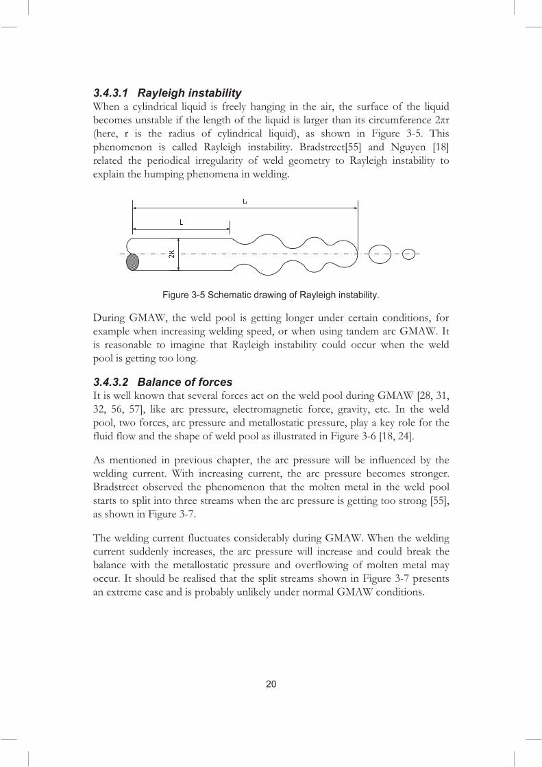
3.4.3.1 Rayleigh instability When a cylindrical liquid is freely hanging in the air, the surface of the liquid becomes unstable if the length of the liquid is larger than its circumference 2�r (here, r is the radius of cylindrical liquid), as shown in Figure 3-5. This phenomenon is called Rayleigh instability. Bradstreet[55] and Nguyen [18] related the periodical irregularity of weld geometry to Rayleigh instability to explain the humping phenomena in welding.
Figure 3-5 Schematic drawing of Rayleigh instability.
During GMAW, the weld pool is getting longer under certain conditions, for example when increasing welding speed, or when using tandem arc GMAW. It is reasonable to imagine that Rayleigh instability could occur when the weld pool is getting too long.
3.4.3.2 Balance of forces It is well known that several forces act on the weld pool during GMAW [28, 31, 32, 56, 57], like arc pressure, electromagnetic force, gravity, etc. In the weld pool, two forces, arc pressure and metallostatic pressure, play a key role for the fluid flow and the shape of weld pool as illustrated in Figure 3-6 [18, 24].
20
As mentioned in previous chapter, the arc pressure will be influenced by the welding current. With increasing current, the arc pressure becomes stronger. Bradstreet observed the phenomenon that the molten metal in the weld pool starts to split into three streams when the arc pressure is getting too strong [55], as shown in Figure 3-7.
The welding current fluctuates considerably during GMAW. When the welding current suddenly increases, the arc pressure will increase and could break the balance with the metallostatic pressure and overflowing of molten metal may occur. It should be realised that the split streams shown in Figure 3-7 presents an extreme case and is probably unlikely under normal GMAW conditions.

COLD LAPS
21
Figure 3-6 Balance between are pressure and metallostatic pressure in high current arc welding (adapted from [18]). Schematic longitudinal section of a weld pool.
Figure 3-7 Split streams in high current GMAW (adapted from [55]. Schematic cross section of a weld.

22
3.4.3.3 Momentum of transferred metal Another important cause of overflow could be the momentum of molten metal in the weld pool. In GMAW, the droplets will be transported through the arc to the weld pool. The droplets get in contact with the weld pool with a certain velocity and transfer a certain momentum. If the velocity of the droplets is making an angle with the axis of the wire, the molten metal will get a lateral momentum [18]. The situation is illustrated in Figure 3-8. If the momentum becomes high enough, overflow could occur.
Figure 3-8 Lateral momentum of transferred molten metal. (Adapted from [18])
3.4.3.4 Surface tension It is well known that the wettability of a liquid on a solid surface is determined by the surface tension between the phases, i.e. �Ls � Lg � sg , as shown in Figure 3-9. The base metal surface condition will influence the wettability between the molten metal in the weld pool and the base metal surface.

COLD LAPS
23
Figure 3-9 Wettability of a liquid on a solid surface.
Bradstreet [55] performed an experiment to weld on a base metal with two surface conditions, i.e. one side with oxides, and the other side cleaned and free from oxides. The results showed that it is easier for the molten metal to wet and get onto the base metal surface for the clean surface condition whereas it tends to form undercut for the oxide surface condition, as shown in Figure 3-10.
Figure 3-10 Influence of surface condition of base metal on splitting of streams. Schematic cross section of a weld. (Adapted from [55])
Surface tension of molten metal also plays a key role for the convection of the weld pool. Many studies [58-67] have addressed the influence of surface active elements on the weld pool fluid flow which in turn strongly alter the weld pool shape.
For a liquid, atoms close to a free surface have partially unfilled coordination shells requiring higher energy states which result in surface tension or surface energy [61]. The group VI elements, oxygen, sulphur, selenium, and tellurium, are usually regarded as the common surface active elements [61, 64] for steel. Nitrogen and silicon are also surface active but to a lesser degree [49, 68]. In the
Bradstreet [55] performed an experiment to weld on a base metal with two surface conditions, i.e. one side with oxides, and the other side cleaned and free from oxides. The results showed that it is easier for the molten metal to wet and get onto the base metal surface for the clean surface condition whereas it tends to form undercut for the oxide surface condition, as shown in Figure 3-10.

24
1.5
1.6
1.7
1.8
1.9
2
1600 1700 1800 1900 2000 2100 2200 2300 2400
����������� ��
����
��
�������������
Figure 3-11 Surface tension as a function of temperature and sulphur content in a Fe-S system. (Adapted from [64])
Numerical studies [64-66] have shown different fluid flow patterns of the weld pool for different sulphur contents. For the sulphur free steel (S=0 ppm) [64], surface tension has a linear relationship with temperature. The peak of surface tension occurs at the lowest temperature location of the weld pool which is located at the edge. By the Marangoni effect, an outward fluid flow is generated, as shown in Figure 3-12.
When sulphur content is increased to 155 ppm, the curve of the correlation between surface tension and temperature start to bend. The maximum surface tension temperature decreases. Therefore, the point having maximum surface tension on the weld pool surface starts to move towards the centre of the weld pool and will be located somewhere between the weld pool centre and the edge.
weld pool, the most important surface active elements are oxygen and sulphur [68, 69].
It has been reported [64] that the presence of sulphur can alter the relation between the surface tension and the temperature for the molten metal. When the sulphur content increases, the temperature of maximum surface tension is increased, as shown in Figure 3-11. As a consequence the fluid flow pattern will depend on the sulphur content of weld pool.

COLD LAPS
25
Thus, three vortexes are generated: one is the fluid flow controlled by electromagnetic force; one is an outward fluid flow caused by the Marangoni effect; one is the inward fluid flow caused by the Marangoni effect, as shown in Figure 3-13.
For a sulphur content of 160 ppm, the peak surface tension point moves further towards the centre of the weld pool and merges with the electromagnetic controlled fluid flow. Thus an inward fluid flow pattern (shown in Figure 3-14) is generated which results in larger penetration and a lower width/penetration ratio of the weld.
Figure 3-12 Fluid flow for sulphur content 0 ppm. (Adapted from [64])
Figure 3-13 Fluid flow pattern for sulphur content 155 ppm. (Adapted from [64])

26
Figure 3-14 One fluid flow generated for sulphur content 160 ppm.
The similar effects of oxygen on fluid flow within the weld pool have been confirmed by many studies [59, 60, 66, 70]. For example, an experimental study [62] showed that oxygen can increase penetration. An inward Marangoni flow was suggested to explain the mechanism and was confirmed with a high speed video camera [62]. Similar as for sulphur, a three vortexes fluid flow pattern was reported [66] in a numerical analysis study on the influence of oxygen on weld pool convection.

27
4 Oxide formation
During GMAW, the melt experiences high temperatures and, at the same time, the shielding gases usually contain certain amounts of active gases, e.g. oxygen (O2) or carbon dioxide (CO2), to achieve better arc stability. Therefore, oxidation of the molten metal, including both droplets and weld pool is inevitable [71].
It is well known that elements, like silicon and manganese, are applied as desoxidants in welding consumables [71, 72]. As mentioned in the previous chapter, oxides of manganese and silicon were found in the cold laps. Therefore, it is necessary to understand the oxidation processes in GMAW, particularly for manganese and silicon. In this chapter, the conditions for oxidation and possible reactions during the welding process will be described. First, however, some fundamental facts regarding manganese and silicon will be given.
4.1 Metallurgy of manganese
Manganese is a greyish-white metallic element with an atomic weight of 54.9 and a melting point of 1245°C. A certain quantity of manganese can commonly be found in most steels, as it is a helpful additive in iron alloys. Manganese has a stronger affinity to oxygen and sulphur than iron. When added to molten iron, manganese reacts with oxygen to form manganese oxide (MnO). Hence, manganese is a deoxidizer for iron, but it is still less strong than aluminium and silicon. In the melt, manganese can also react preferentially with sulphur to form manganese sulphide (MnS).
Manganese is commonly used as an alloying addition in all types of carbon and low alloy steel base and filler metals. The purpose of manganese can generally be summarized as being threefold [49]:
�� ���� ����������� ������� ���� ���� �������� ������ ���
�� �� ��������������� � �������������������"����� ������� ��
�� #���� ���� �� ����� ������

28
4.2 Metallurgy of silicon
Silicon has an atomic weight of 28 and a melting point of 1427°C. Silicon is used in steels as a deoxidizing agent. The amount of silicon to be added is slightly in excess of the quantity needed to combine with the oxygen. Silicon and oxygen react vigorously to liberate a large amount of heat, and silicon dioxide (SiO2) is formed. The silicon dioxide can either escape to the molten metal surface or form inclusions in the solidified steel. Usually steel contain silicon in the range from about 0.10 to 0.30 percent. Silicon can also be used as a ferrite strengthener, and it is stronger in this respect than most other commonly used alloying elements. Also, silicon is a strong hardenability promoter and can be used to improve fluidity.
4.3 Oxidation of manganese and silicon
When used in combination manganese and silicon can form complex oxides that will remain liquid at the freezing temperature of the steel [49]. The deoxidation product formed is essentially a liquid mixture of MnO and SiO2 with little iron oxide [48] which can be simplified as presented in Eq. 4-1.
�� � ! � "# $ �� !#%�&� 4-1
According to Turkdogan [48], the products of the complex Mn-Si-Fe-O system will be determined by three factors, i.e. the content of silicon, the content of manganese, and the temperature, as shown in Figure 4-1. For a given temperature, when the composition lies above the curve, the manganese does not contribute to the desoxidation reaction. Then solid silica is formed as the desoxidation product. If the content is below the curve, the desoxidation product is molten manganese silicate.
However, the desoxidation probably differs considerably from equilibrium conditions in GMAW because of the rapid cooling.
Grong and Christensen [50] studied the oxidation reaction during GMAW for different shielding gases. They described the possible reactions at different locations in the welding process, i.e. electrode tip/droplet (region ‘a’), arc plasma (region ‘b’) and the hot (region ‘c’) and colder (region ‘d’) parts of the weld pool, as shown in Figure 4-2.
In region ‘a’ shown in Figure 4-2, CO is formed during droplet formation. When reaching the critical CO gas pressure, the carbon reaction is blocked and silicon and manganese will take over and control the oxygen level in the molten metal. As a consequence manganese silicate slag particles are formed. A certain

OXIDE FORMATION
29
amount of silicon was lost which probably is a result of a gaseous (SiO) formation.
Figure 4-1 Products of oxidation of silicon and manganese at equilibrium in molten steel. (Adapted from [48])
Figure 4-2 Four regions in GMAW a: droplet region; b: arc region; c: hot region of weld pool; d: colder region of weld pool. (Adapted from [50])
In the arc plasma region (region ‘b’ in Figure 4-2), the droplet temperature is about 2400°C and the precipitated manganese silicate slag which formed in region ‘a’ dissolves in the metal upon heating. Further absorption of oxygen will

30
be prevented due to formation of metal vapour. A certain amount of Mn is probably lost due to vaporisation under the high temperature experienced by the droplet in the arc plasma. Welding fumes are then formed by the metal vapour reacting with oxygen [50].
In the hot part of the weld pool (region ‘c’ in Figure 4-2), the temperature is in the range 2000°C to 1800°C. The plasma jet blows the Mn and Fe vapour away and provides a steady supply of oxygen which is dissolved in the weld pool. At the same time manganese silicate slag formation takes place preventing the oxygen concentration from exceeding a certain limit. A separation of microslag proceeds continuously under the existing turbulent conditions.
In the colder part of the weld pool (region ‘d’ in Figure 4-2), the temperature is below 1800°C. Silicon and manganese react further with dissolved oxygen upon cooling. The oxygen content was found highly unpredictable which it is closely linked to the silicon and manganese concentrations in the weld metal.

31
5 Experimental procedures and materials
The experimental techniques used in the present study are presented in this chapter. A summary of experimental methods and materials is listed in Table 5-1 for the appended papers.
Table 5-1 Summary of experimental methods and materials used in appended papers
� Base�metal�
Welding�consumables�
Shielding�gas�
Controlled�atmosphere� Preheating� Evaluation�
method�
Paper�I�
Domex�355�MC
ESAB��OK�Autrod�12.51
92%Ar�8%CO2
/ /� LOM�and�SEM&EDS
Paper�II�
Domex�355�MC
ESAB��OK�Autrod�12.51
Ar�or��CO2
Sealed�chamber� /� LOM
Paper�III�
Domex�355�MC
ESAB��OK�Autrod�12.51
Ar�or��CO2
Sealed�chamber� /� LOM�and�
SEM&EDS
Paper�IV�
Domex�355�MC
ESAB��OK�Autrod�12.51 CO2 /�
25°C,�250°C,�475�°C�
LOM�and�SEM&EDS
Paper�V�
Domex�355�MC
ESAB��OK�Autrod�12.51 CO2 /
25°C,�250°C,�475�°C�
LOM�and�SEM&EDS
5.1 Base metal and welding consumables
In the experimental work of this study, Domex 355 MC was used as base metal, and ESAB OK Autrod 12.51 was used as welding wire.
Domex 355 is a hot rolled cold forming steel which meets steel S355 MC in EN-10149-2. It is used in, e.g. manufacturing of truck chassis, cranes and earthmoving machines. ESAB OK Autrod 12.51 is a copper coated solid wire complying with ISO 14341-A G3Si1. The chemical compositions of Domex 355 and ESAB OK Autrod 12.51 are shown in Table 5-2 [73, 74].

32
Table 5-2 Nominal Chemical composition of Domex 355 MC (wt.%)
C Si Mn P S Al V Ti
Domex 355 MC <0.10 <0.03 <1.50 <0.025 <0.010 >0.015 <0.20 <0.15
OK Autrod 12.51
0.06-0.14
0.70-1.00
1.3-1.60 <0.025 <0.025 - - -
5.2 Shielding gases
It is well known that the shielding gas can have a significant influence on the welding process. A gas mixture of argon and carbon dioxide (Ar-CO2) is the most common shielding gas used in GMAW. For the Ar-CO2 shielding gases, the CO2 content can change the droplet transfer mode, affecting the penetration, and influence spatter generation, whereas a higher amount or pure argon will decrease the arc stability.
In the present study, three types of shielding gases were utilized in welding experiments ( see also Table 5-1). The first shielding gas used was the mixed gas 92%Ar-8%CO2. This mixed shielding gas is commonly used in industry for the welding of Domex 355MC base metal with OK Autrod 12.51 wire.
Since one research question was the effect of Mn-Si oxides on cold lap formation, an experiment was designed with two types of shielding gases: one was a heavily oxidising gas, i.e. CO2 ( 99.98%) and the other was an inert gas, i.e. Ar ( 99.9999%).
5.3 Controlled atmosphere setup
In order to create a non-oxidising environment, the welding experiments were carried out in a sealed chamber filled with Ar, as shown in Figure 5-1. The chamber is a welded stainless steel structure sealed with plastic in a way that permits free movements of the robot arm which holds the welding gun inside the chamber. The air from the chamber was removed through a gas outlet on the top of the chamber while filling with shielding gas through the gas supply nozzle at the bottom of the chamber. The content of the oxygen inside the chamber was measured with an oxygen analyser mounted on the robot arm at a height of 600-800 mm above the bottom of the chamber. In the pure Ar welding experiment, the oxygen content was kept in the range of 25-50 ppm. The setup of the sealed chamber is shown in Figure 5-1.

EXPERIMENTAL PROCEDURES AND MATERIALS
33
Figure 5-1 Schematic figure of sealed chamber experimental setup.
5.4 Welding
All welding experiments were performed with mechanised tandem GMAW. Migatronic FLEX 5000 power sources were used together with a ABB IRB 2400 Robot.
Table 5-3 Welding parameters.
Paper�
Voltage�[V]� Wire�feed�
speed*�[m/min]�
Current�[A]�Travel�speed�[mm/s]�
Type�of�Shielding�
gas�Leading�wire�
Trailing�wire�
Leading�wire�
Trailing�wire�
Paper�I�
30� 27� 12� 283� 276� 13�
92%Ar�8%CO2�
33� 36� 15� 327� 349� 17�30� 27� 15� 314� 312� 17�33� 30� 12� 296� 281� 17�33� 30� 15� 326� 310� 13�30� 33� 12� 287� 303� 17�33� 36� 12� 287� 311� 13�30� 33� 15� 320� 336� 13�
Papers�II�and�III�
33� 36� 15� 327� 349� 17�Ar�and�CO2�
Papers�IV�and�V�
33� 36� 15� 327� 349� 17� CO2�
The welding parameters used in the experimental work are presented in Table 5-3, shielding gases are also presented in Table 5-1 and details on welding

34
consumable and base material are given in Table 5-2. In the first experiment, the aim was to investigate the correlation between welding parameters and cold lap formation. Therefore, a welding parameter matrix was statistically designed using the MODDE software (for Paper I). In the other experiments, a fixed parameter set which was found to give a higher cold lap frequency was used.
5.5 Light optical microscope, SEM and EDS
A light optical microscope uses visible light and a lens system to magnify images of among others metallographic samples. Digital images can be captured and the dimension of the object can be measured with help of a suitable software (in this work Picsara). In this study, the light optical microscope was used to identify cold laps and evaluate their dimensions on cross sections.
A scanning electron microscope (SEM) is a materials investigation tool that can produce high resolution microstructure images with the help of a high-energy scanning electron beam. For such investigations, an electron beam is accelerated using a high voltage field in the electron gun. The high energy electrons interact with the atoms at or near the sample surface and produce signals, e.g. secondary electrons, back-scattered electrons and characteristic X-rays, as shown in Figure 5-2. The electrons emitted from the specimen can be detected and used to produce an image of the sample surface. The secondary electron (SE) image and backscattered electron (BSE) image are the most common image modes in SEM.
Figure 5-2 Signals produced in SEM
Energy-dispersive spectrometry (EDS) is an analytical technique used for chemical characterization of a material. As mentioned above, a characteristic X-ray can be emitted when the high energy electron beam hits the sample. The

EXPERIMENTAL PROCEDURES AND MATERIALS
35
number and energy of the X-rays emitted from a specimen can be measured using an energy-dispersive spectrometer. By analysing the X-rays, EDS allows the identification of different elements in the sample. The accuracy of the EDS spectrum can be affected by many factors. Windows in front of the detector can absorb the low-energy X-rays (i.e. EDS detectors cannot detect elements with an atomic number of less than 4, i.e. H, He, and Li). Also, many elements will have overlapping peaks (e.g. Ti-K$ and V-K', Mn-K$ and Fe-K'). The accuracy of the spectrum can also be affected by the nature of the sample. X-rays can be generated by any atom in the sample that is sufficiently excited by the incoming beam. These X-rays are emitted in any direction, and so they may not all escape the sample. The likelihood of an X-ray escaping the specimen, and thus being detected and measured, depends on the energy of the X-ray and the amount and density of the material it has to pass through. This can result in reduced accuracy in the case of inhomogeneous and rough samples.
Two types of SEM and EDS systems were used in this study: one is a high resolution field emission type LEO 1550 Gemini equipped with an Oxford EDS system; another one is a Bruker Quantax 800 system. The detector is an X-flash 4010 with a resolution of 127 eV for the Mn-K peak. In the present study, the cold laps were characterised by SEM-EDS evaluation on cross sections.
Preparation of metallographic samples includes sectioning, mounting, polishing and etching (if necessary). In the present study, a Struers Secotom 10 was used for sectioning, a Simpliment 2000 automatic mounting press for mounting, and a Buehler Powerpro 5000 for grinding and polishing the samples. Epoxy mounting compound (Buehler EpoMet G) was used for preparation of specimens for light optical microscopy and a conductive phenolic (Buehler KonductoMet) for SEM-EDS specimens. In the present study, the welds produced by GMAW were sectioned at the locations suspected to contain cold laps, mounted and polished.


37
6 Summary of results
In this chapter, the main results from the work are presented. A new classification system is introduced and results of studies on the influence of oxide formation and temperature on formation of cold laps are summarised.
6.1 Novel classification of cold laps
In Paper I, results from a thorough study of cold laps formed in tandem GMAW are presented. It was found that the previously used classification of cold laps was not sufficient to describe the various types of cold laps identified. A novel classification was therefore introduced based on the appearance and assumed formation mechanism, i.e. spatter cold lap, overlap cold lap and spatter-overlap cold lap, shown in Figure 6-1.
Weld
R
Figure 6-1 Three types of cold laps: spatter cold lap, overlap cold lap, spatter-overlap cold lap.
The first type is named spatter cold lap which is formed when a spatter is situated close to the weld toe so that the spatter is fused and partially included in the weld. Typically a spatter cold lap has a semi circular shape protruding from

38
the weld toe. The size depends on the size of the spatter, which can range from several millimetres down to a few microns.
The second type is named overlap cold lap, and is believed to be caused by a local overflow of the molten metal in the weld pool with the incomplete fusion of the overflowing metal with the base metal surface. Overlap cold laps are usually semi elliptical and can be a few millimetres in the longitudinal direction of the weld. It is also possible to find cold laps along the entire weld toe (in the longitudinal direction of the weld) continuously. These are, however, usually caused by a poor surface condition of the base metal and improper welding parameters and are therefore not discussed further (see also Figure 1-2).
The third type, not previously discussed in literature, is referred to as spatter-overlap cold lap, and can be regarded as a combination of an overlap and a spatter cold lap. This type usually have a worm-like shape and can extend several millimetres from the weld toe.
6.2 Influence of Mn-Si oxides
In Paper I, Mn-Si oxides were found in the lack of fusion formed between spatter and base metal. The Mn-Si oxide rich area was mainly situated close to the edge of the lack of fusion, as shown in Figure 6-2. Further studies were performed based on observation in Paper I and are presented in Paper II and III. The influence of Mn-Si oxides were studied in details for all three types of cold laps in welds produced in either oxidising or non-oxidising environment.
It was found that the overlap cold laps formed in non-oxidising welding atmospheres were much smaller than those formed when using an oxidising shielding gas. It was also seen that no Mn-Si oxides appeared in the overlap cold laps under non-oxidising welding conditions. Therefore the conclusion is that formation of Mn-Si oxides have a significant influence on overlap cold lap occurrence.
SEM-EDS analyses of the spatter and base metal surfaces showed that the Mn-Si oxides only appeared on the spatter surface compared with base metal. Thus, it was suggested that the Mn-Si oxides in cold laps came mainly from the oxidisation of droplets before they reached the weld pool or base metal surface. In Paper IV it was also shown that Mn-Si oxides were evenly distributed within small spatters (< 1.0 mm in diameter) suggesting that the rapid cooling didn’t permit oxides to redistribute to the surface.

SUMMARY OF RESULTS
39
Figure 6-2 Oxide distribution in a cold lap: the oxide tends to be located at the edge of cold laps.
It is known from previous studies [10, 26] that oxides (rust) on the base material surface will increase the tendency of cold lap formation. An interesting observation (Paper IV) was therefore that a blasted surface can enhance the lack of fusion formation by making air entrapment in the interface easier. It is consequently not enough to clean the base material surface before welding but the surface roughness also needs to be controlled.
6.3 Influence of temperature
As shown in Paper II, cold laps can be found also under non-oxidising welding conditions, although the size tends to be small. Other factors therefore also have to be considered when trying to understand formation of cold laps. The temperature of base metal, spatters and weld pool was seen as a factor likely to influence the cold lap formation and was therefore studied in papers (Paper III to Paper V).
First, the effect of the temperature of spatter was studied in Paper III. The formation mechanisms of the lack of fusion between a spatter and base metal can be assumed to be the same as in formation of spatter cold laps. For the sake of simplifying, the analysis was performed on the spatters at some distance from the weld toe. Spatter diameter and spatter distance (the distance between the centre of spatter and the centre line of weld) were considered as indicators of the spatter temperature. A larger spatter travelling a shorter distance is likely to have a higher temperature when hitting the base metal surface. The ratio of lack

40
of fusion (RLoF) was introduced to express the fusion between spatter and base metal, as shown in Figure 6-3. Results showed that smaller spatters (i.e. < 1.0 mm in diameter) have 100% RLoF in the interface between spatter and base metal. With increasing spatter size, the RLoF decreases linearly with size. It was therefore concluded that spatter temperature is a significant factor in formation of spatter related cold laps.
Figure 6-3 Definition of RLoF.
Next, the temperature of base metal was studied in Paper IV (for spatter/base metal lack of fusion) and Paper V (for overlap cold laps). It was found that the preheating temperature of base metal significantly influences the fusion between spatter and base metal. The effect of preheating temperature was most significant for larger spatter (diameter between 1.0-2.0 mm) with a higher preheating temperature resulting in better fusion. For smaller spatter (< 1.0 mm in diameter) the effect was smaller with a high RLoF (varying from 89% to 100%) for all preheating temperatures.
For overlap cold laps, the influence of temperature was studied both regarding occurrence frequency and size of overlap cold laps. The results showed that the preheating temperature of the base metal significantly influenced the frequency of overlap cold laps resulting in formation of fewer cold laps with increasing preheating temperature. However, no clear correlation could be found between the preheating temperature of base metal and the depth of overlap cold laps (size in transverse direction of weld).

41
7 Discussion
7.1 Classification
Three types of cold laps were identified and classified based on appearance and assumed mechanism of formation: one is caused by spatters, one is caused by overflow of molten metal from the weld pool and one is caused by a combination of spatter and overflow. It should be noted that a spatter also can be embedded in the the weld metal completely and form a cold lap as reported by Farajian-Sohi and Järvstråt [13], schematically shown in Figure 7-1. This situation can be regarded as a special case of spatter cold laps. Obviously, minimization of spatter generation will minimize the number of spatter related cold laps.
Figure 7-1 A spatter cold lap entirely embedded in the weld pool.
7.2 Formation mechanisms
The results of Paper I and Paper II suggest that overlap cold laps form when the molten metal from the weld pool gets in contact with the solid surface of the base metal and forms a micro-lack of fusion. Usually, an irregularity at the weld toe indicates the location of an overlap cold lap, as shown in Figure 7-2. The irregularity suggests an overflow of molten metal during welding which results

42
in contact between the molten metal and solid base metal surface without fusion of the two surfaces. Then a micro-lack of fusion, i.e. a cold lap, is formed.
Figure 7-2 Schematic top view of the irregularity at the weld toe at the location of an overlap cold lap.
An overflow or a spatter is a necessary prerequisite for formation of cold laps but whether a cold lap will actually form depends also on other factors. As shown by the results from Paper II to Paper V, oxides and temperatures of base metal and spatter are two significant factors in the cold lap formation process.
All three types of cold laps studied in Paper II and Paper III had common features. Oxides fully or partly filled the cold laps and the Mn-Si oxides was preferentially located at the edge, as shown in Figure 6-2. It is well known that oxides have very low thermal conductivity compared with steel, as presented in chapter 3. They therefore probably act as a heat insulator and prevent the heat transfer from the molten metal (either of overflow or spatters) to the solid base metal. As a consequence heat transfer will be insufficient to melt the base metal surface and fusion will not take place. In short, a cold lap is formed.
As Mn-Si oxides can play a significant role in cold lap formation, it is important to understand how these form during GMAW. According to Turkdogan [48], the oxidation products of the manganese-silicon-iron system is dependent on the relative contents of manganese and silicon (presented in chapter 4). Mn-Si oxides found in cold laps were shown to have a similar chemical composition as the Mn-Si oxides found on (Paper II) and within (Paper IV) spatters. Therefore, it is reasonable to believe that the Mn-Si oxides found in cold laps were generated during the droplet period, and then transported to weld pool or base metal surface.
Another major factor influencing cold lap formation is the temperature of spatter, base metal and possibly overflowing molten metal. A higher temperature of spatter or overflow means that more energy is available to

DISCUSSION
43
permit fusion with the base metal. At the same time a higher base metal start temperature means that less energy is required for heating and fusion. Thus higher temperatures will reduce the risk of cold lap formation which is supported by the results in Paper IV and Paper V.
Cold laps, however, were found also when welding in an inert argon atmosphere (Paper II) or with preheating of the base metal to 475°C (Paper V). Thus there is no guarantee that cold laps can be avoided completely by minimizing oxidation or using preheating. This illustrates that there is a complicated interaction between different factors contributing to cold lap formation or that other factors than oxide and temperature have to be considered.
As mentioned above, overflow is a prerequisite for overlap cold lap formation. Several possible and probably interacting mechanisms, as discussed in some details in Paper VI, could contribute:
� Rayleigh instability can be a contributing factor, more so for longer weld pools as mentioned in chapter 4.
� The balances between forces acting on the weld pool, as discussed in chapter 3, are important. During GMAW, it is well known that the arc force varies as current and voltage vary. When the arc force varies, this has to be balanced by the metallostatic pressure in the molten metal and fluctuations in the shape will be an inevitable consequence.
� Droplets hitting the weld pool surface will transfer a lateral momentum to the weld pool, as presented in Figure 3-8. An overflow could occur when the lateral momentum gets high enough.
� Split streams were observed in the GMAW experiment performed by Bradstreet [55] (presented in chapter 3) for high current welding. Two streams were deposited on the base metal, one on each side. This tendency to form split streams could possibly contribute to overflow although the currents used under normal welding conditions are smaller than those used by Bradstreet [55].
� All of the above phenomena will affect the fluid flow pattern of the weld pool and the more unstable the flow conditions are the more likely it is a fluctuation will result in overflow. Obviously an outward fluid flow pattern is more likely to cause an overflow. The content of surface active elements, such as sulphur, affecting the flow pattern will therefore also be of importance. As presented in chapter 4, the fluid flow pattern will alter from outward to inward with increasing sulphur content of the weld pool. A careful control of sulphur and other surface active elements is therefore important. Arc and weld pool physics and fluid dynamics are very complex and governed by a multitude of interacting
44
factors. It is therefore important to be aware that the mechanisms discussed above are all interacting and there are most like other factors that contribute as well. Further investigations, experimentally and numerically, are therefore needed to get a more comprehensive understanding of the overflow and cold lap formation mechanisms.
7.3 How to avoid cold laps
As has been discussed above there is at present no known way to completely avoid formation of cold laps in GMAW. However, based on the results of the experimental studies and the discussion above, some sugeestions can be given regarding how to minimize the number and size of cold laps:
� Welding in a non-oxidising environment will give less cold laps. � Welding on a clean and preheated work piece would be beneficial to
reduce the risk of cold laps, particularly for overlap cold laps. � Reduction of spatter during welding obviously contribute to suppress
formation of spatter related types of cold laps. � Having an as stable welding process (arc) as possible will contribute to
decreasing weld pool fluctuations and spatter which in turn could help to suppress overlap cold laps and spatter-overlap cold laps. The use of modern power sources and applying pulsing could be one way of achieving this.

45
8 Conclusions
A series of experiments were performed aiming at getting a better understanding of cold lap formation. The main results are summarized in this chapter.
� A novel classification of cold laps was introduced based on experimental observations. Three types of cold laps were identified. Spatter cold laps which are believed to occur when a spatter is located very near to the weld toe and partly melted by the weld. Overlap cold laps, as the second type, are believed to form due to overflow of molten metal from the weld pool. Spatter-overlap cold laps, as the third type, which can be regarded as a combination of the first two types.
� It was shown that cold laps are partially or fully filled by oxides. The most common oxides are manganese silicon oxides (Mn-Si oxides) which were concluded to be formed by oxidation of droplets.
� Oxides were found to significantly increase the tendency to form cold laps for spatter cold laps and overlap cold laps. Particularly for overlap cold laps, it is found that the depth (in transverse direction of weld) is increased by welding in an oxidizing chamber.
� A blasted surface was found to enhance the lack of fusion formation by making gas entrapment in the interface easier. It is consequently not enough to clean the base material surface before welding but the surface roughness also needs to be controlled.
� The base metal preheating temperature was concluded to be a significant factor in formation of overlap cold laps and both the preheating and the droplet temperature affects formation of spatter cold laps. For overlap cold laps, the occurrence frequency decreases with increased preheating temperature of the base metal. However, no correlation was found between the preheating temperature and the size of overlap cold laps.
� The studies suggest that an efficient way of suppressing cold lap formation would be to ensure that the welding process, in particular the arc, is as stable as possible and to weld on a preheated work piece in a non-oxidizing environment.


47
9 Suggestions for future work
Work that would be valuable for a deeper and more comprehensive understanding of cold lap formation mechanisms include:
� A study on oxidation of droplets and weld pool in GMAW would be useful to confirm the origin of oxides found in cold laps. It would also be helpful to study the movement and behaviour of oxides on the weld pool surface.
� Further studies on the temperature influence on cold lap formation, particularly focusing on the local temperature at the weld toe area.
� A better understanding of overflow mechanisms is imperative to be able to differentiate between contributing effects such as Rayleigh instability, arc force balances, lateral momentum of molten metal in weld pool and fluid flow pattern of weld pool. High speed imaging could be helpful in studying the behaviour of the weld pool.
� A better knowledge of effects of base metal and welding consumables on surface tension and fluid flow of the weld pool would contribute to the understanding of overflow.
� An interesting aspect is the possibility to use a magnetic field to influence the movement of the Mn-Si oxides on/in the weld pool and to control fluctuations and thereby decrease the risk of cold lap formation.
Development of NDT methods capable of detecting cold laps would be a breakthrough. Moreover, formation of cold laps obviously is a complex phenomenon. There might be other aspects worth considering such as the influence of other shielding gases, controlled surface conditions, pulsing, welding of other base materials than steel , dissimilar welding, the use of welding consumables with a composition different form that of the base material etc..


49
References
1. Barsoum, Z., Residual Stress Analysis and Fatigue Assessment of Welded Steel Structures, in Department of Aeronautical and Vehicle Engineering2008, Kungliga Tekniska Högskolan: Stockholm.
2. Nguyen, T.C., D.C. Weckman, and D.A. Johnson, The discontinuous weld bead defect in high-speed gas metal arc welds. Welding Journal, 2007. 86(11): p. 360S-372S.
3. T.R.Gurney, Fatigue of welded structures. 2 ed1979, Cambridge: Syndics of the Cambridge University Press.
4. Leitner, M., et al., Evaluation of fillet weld properties and fatigue behaviour in dependence of welding parameters. Archives of Civil and Mechanical Engineering, 2011. 11(3): p. 651-660.
5. J.L.Otegui, et al., Fatigue crack initiation from defects at weld toe in steel. International Journal of Pressure Vessels and Piping, 1989. 38(5): p. 385-417.
6. Barsoum, Z. and B. Jonsson, Influence of weld quality on the fatigue strength in seam welds. Engineering Failure Analysis, 2011. 18(3): p. 971-979.
7. Tang, F., et al., Research on residual stress reduction by a low frequency alternating magnetic field. Journal of Materials Processing Technology, 1998. 74(1–3): p. 255-258.
8. Y.Y.Fan, et al., Research on short circuiting transfer mode of ultrasonic assisted GMAW method. Science and Technology of Welding and Joining, 2012. 17(3): p. 186-191.
9. Singh, P.J., et al., Influence of weld geometry and process on fatigue crack growth characteristics of AISI 304L cruciform joints containing lack of penetration defects. Science and Technology of Welding and Joining, 2002. 7(5): p. 306-312.
10. J.Samuelsson. Cold laps and weld quality acceptance limits. in Design and Analysis of Welded High Strength Steel Structures. 2002. Stockholm, Sweden: EMAS.
11. Barsoum, Z. and J. Samuelsson, Fatigue assessment of cruciform joints welded with different methods. Steel Research International, 2006. 77(12): p. 882-888.
12. El-Batahgy, A. and B. Zaghloul, Fatigue failure of an offshore condensate recycle line in a natural gas production field. Materials Characterization, 2005. 54(3): p. 246-253.

50
13. M.Farajian-Sohi and N.Järvstråt, A Fractographical Investigation of Weld Toe Imperfections in Tandem Gas Metal Arc Welding. Steel research international, 2006. 77(No.12): p. 889-895.
14. Nascimento, M.P., H.J.C. Voorwald, and J.d.C. Payão Filho, Fatigue strength of tungsten inert gas-repaired weld joints in airplane critical structures. Journal of Materials Processing Technology, 2011. 211(6): p. 1126-1135.
15. L.Lopez.Martinez and P.Korsgren, Characterization of Initial Defect Distribution and Weld Geometry in Welded Fatigue Test Specimens, in Fatigue under spectrum loading and in corrosive environments, A.F.Blom, Editor 1993, EMAS: Denmark. p. 3-21.
16. Dimitrakis, S.D. and F.V. Lawrence, Improving the fatigue performance of fillet weld terminations. Fatigue & Fracture of Engineering Materials & Structures, 2001. 24(6): p. 429-438.
17. Moon, H.S. and S.J. Na, A neuro-fuzzy approach to select welding conditions for welding quality improvement in horizontal fillet welding. Journal of Manufacturing Systems, 1996. 15(6): p. 392-403.
18. Nguyen, T.C., et al., High speed fusion weld bead defects. Science and Technology of Welding and Joining, 2006. 11(6): p. 618-633.
19. Standardization, E.C.f., Welding and allied processes-Classification of geometric imperfections in metallic materials-Part 1: Fusion welding, in BS EN ISO 6520-12007, Multiple: London.
20. Volvo weld quality standard, in STD181-00042008: Sweden. 21. L.Holst, et al. High productive MAG-Welding- Weld toe defects -
A new detection method. in Welded High-Strength Steel Structures. 1997. Stockholm, Sweden: EMAS.
22. L.Lopez.Martinez, A.F.Blom, and J.Samuelsson. Weld defects before and after post weld treatment for MAG and high-productivity MAG welding. in Welded High-Strength Steel Structures. 1997. Stockholm, Sweden: EMAS.
23. Nguyen, T.C., et al., The humping phenomenon during high speed gas metal arc welding. Science and Technology of Welding and Joining, 2005. 10(4): p. 447-459.
24. Mendez, P.F. and T.W. Eagar, Penetration and defect formation in high-current arc welding. Welding Journal, 2003. 82(10): p. 296S-306S.
25. M.Farajian-Sohi, N.Järvstråt, and M.Thuvander. Effect of Welding Parameters on Formation of Toe Imperfections in Tandem Gas Metal Arc Welding in 7th International Conference on Trends in Welding Research. 2005. Georgia, USA: ASM.

REFERENCES
51
26. J.Hedegård, et al. The influence of welding parameters on the size and distribution of weld defects for various weld methods. in VTT Symposium 156:Fatigue Design 1995. 1995. Helsinki: VTT Offset print Espoo 1995.
27. Wikipedia, F.e.o. Gas metal arc welding. 2013; Available from: http://en.wikipedia.org/wiki/GMAW.
28. K.Weman, Welding Process Handbook2003: CRC Prss Inc (5 Aug 2003).
29. R.L.O'Brien, WELDING PROCESS. Eighth ed, ed. R.L.O'Brien. Vol. 2. 1995, MIAMI: AMERICAN WELDING SOCIETY.
30. Pritchard, D., Soldering, Brazing & Welding-A Manual Of Techniques2001: The Crowood Press.
31. L.Jeffus and H.V.Johnson, Welding: Principles and Applications. 2nd ed1988.
32. L.P.Connor, WELDING TECHNOLOGY. Eighth ed. Vol. 1. 1987, Miami: AMERICAN WELDING SOCIETY.
33. Stenbacka, N. and K.-A. Persson, Shielding Gases for Gas Metal Arc Welding. Welding Journal, 1989. NOVEMBER(42): p. 41-47.
34. Haddad, G.N. and A.J.D. Farmer, Temperature measurements in gas tungsten arcs. Welding Journal, 1985. 24: p. 339–342s.
35. Choquet, I., et al., Numerical simulation of Ar-x%CO2 shielding gas and its effect on an electric welding arc, 2011, International Institute of Welding: IIW. p. 12.
36. Choquet, I., A.J. Shirvan, and H. Nilsson, On the choice of electromagnetic model for short high-intensity arcs, applied to welding. Journal of Physics D: Applied Physics, 2012. 45(20): p. 205203.
37. Dunn, G.J. and T.W. Eagar, Metal vapors in gas tungsten arcs: part ii. theoretical calculations of transport properties. Metallurgical and Materials Transactions A, 1986. 17(10): p. 1865-1871.
38. Rat, V., et al., Transport coefficients including diffusion in a two-temperature argon plasma. Journal of Physics D: Applied Physics, 2002. 35(10): p. 981.
39. Murphy, A.B., et al., Modelling of thermal plasmas for arc welding: the role of the shielding gas properties and of metal vapour. Journal of Physics D-Applied Physics, 2009. 42(19).
40. Kumar, A. and T. Debroy, Heat transfer and fluid flow during gas-metal-arc fillet welding for various joint configurations and welding positions. Metallurgical and Materials Transactions a-Physical Metallurgy and Materials Science, 2007. 38A(3): p. 506-519.

52
41. DebRoy, T., Mathematical Modelling of Weld Phenomena1993, Cambridge, Great Britain: British Library Cataloguing-in-Publication Data. 24-38.
42. Winkler, C., et al., Mathematical Modelling of Weld Phenomena 4, ed. H.K.D.H. Bhadeshia1998, Cambridge, Great Britain: IOM Communications Ltd. 37-69.
43. Naidu, D.S., S. Ozcelik, and K.L. Moore, Modeling, Sensing and Control of Gas Metal Arc Welding2003, Oxford: Elsevier Science Ltd.
44. Zacharia, T. and S.A. David, Mathematical Modelling of Weld Phenomena1993, Cambridge, Great Britain: British Library Cataloguing-in-Publication Data. 3-22.
45. Schnick, M., et al., Modelling of gas–metal arc welding taking into account metal vapour. Journal of Physics D: Applied Physics, 2010. 43(43): p. 434008.
46. Schnick, M., et al., Metal vapour causes a central minimum in arc temperature in gas–metal arc welding through increased radiative emission. Journal of Physics D: Applied Physics, 2010. 43(2): p. 022001.
47. Baradi, D., Control strategies and inspection methods for welded part, in Faculty of Technology and Science, Department of Mechanical and Materials Engineering2013, Karlstad University: Karlstad, Sweden. p. 75.
48. E.T.Turkdogan. Deoxidation of steel. in Chem. Metall. of Iron and Steel. 1973. Sheffield, U.K.: The Iron and Steel Institution.
49. Linnert, G.E., Welding metallurgy : carbon and alloy steels : fundamentals ed. 4. Vol. 1. 1995, Miami, USA: American Welding Society
50. O.Grong and N.Christensen, Factors Controlling MIG Weld Metal Chemistry. Scandinavian Journal of Metallurgy 1983. 12: p. 155-165.
51. O.Grong, et al., A model for the silicon-manganese deoxidation of steel weld metals. Metallurgical Transactions A, 1986. 17A: p. 1797-1807.
52. Cengel, Y.A., INTRODUCTION TO THERMODYNAMICS AND HEAT TRANSFER. McGRAW-Hill series in Mechanical Engineering, ed. J.P. Holman and J.R. Lloyd1997, United States: McGRAW-Hill. 922.
53. Zacharia, T., S.A. David, and J.M. Vitek, EFFECT OF EVAPORATION AND TEMPERATURE-DEPENDENT MATERIAL PROPERTIES ON WELD POOL DEVELOPMENT. Metallurgical Transactions B-Process Metallurgy, 1991. 22(2): p. 233-241.

REFERENCES
53
54. Kim, C.H., W. Zhang, and T. DebRoy, Modeling of temperature field and solidified surface profile during gas-metal arc fillet welding. Journal of Applied Physics, 2003. 94(4): p. 2667-2679.
55. Bradstreet, B.J., Effect of Surface Tension and Metal Flow on Weld Bead Formation. Welding Journal, 1968. 47(6): p. 314s-322s.
56. K.Weman and G.Lindén, MIG welding guide2006, Cambridge: Woodhead.
57. Kreith, F. and M. S.Bohn, Principles of heat transfer, ed. 62001, Pacific Grove, Calif: Brooks/Cole, cop.
58. Fan, D., et al., YAG laser welding with surface activating flux. China Welding (English Edition), 2003. 12(2): p. 83-86.
59. Fujii, H., et al., Development of an advanced A-TIG (AA-TIG) welding method by control of Marangoni convection. Materials Science and Engineering a-Structural Materials Properties Microstructure and Processing, 2008. 495(1-2): p. 296-303.
60. Lu, S.P., et al., Effect of oxygen content in He-O-2 shielding gas on weld shape in ultra deep penetration TIG. Science and Technology of Welding and Joining, 2007. 12(8): p. 689-695.
61. McNallan, M.J. and T. Debroy, Effect of temperature and composition on surface tension in Fe-Ni-Cr alloys containing sulfur. Metallurgical Transactions B, 1991. 22(4): p. 557-560.
62. Tanaka, M., et al., Effects of activating flux on arc phenomena in gas tungsten arc welding. Science and Technology of Welding and Joining, 2000. 5(6): p. 397-402.
63. Toit, M.D. and P.C. Pistorius, Nitrogen control during autogenous arc welding of stainless steel - Part 1: Experimental observations. Welding Journal (Miami, Fla), 2003. 82(8): p. 219/S-224/S.
64. Wang, Y., Q. Shi, and H.L. Tsai, Modeling of the effects of surface-active elements on flow patterns and weld penetration. Metallurgical and Materials Transactions B: Process Metallurgy and Materials Processing Science, 2001. 32(1): p. 145-161.
65. Wang, Y. and H.L. Tsai, Effects of surface active elements on weld pool fluid flow and weld penetration in gas metal arc welding. Metallurgical and Materials Transactions B: Process Metallurgy and Materials Processing Science, 2001. 32(3): p. 501-515.
66. Zhao, Y.Z., Y.W. Shi, and Y.P. Lei, The study of surface-active element oxygen on flow patterns and penetration in A-TIG welding. Metallurgical and Materials Transactions B-Process Metallurgy and Materials Processing Science, 2006. 37(3): p. 485-493.
67. Zhao, Y.Z., H.P. Zhou, and Y.W. Shi, The study of surface active element on weld pool development in A-TIG welding. Modelling
54
and Simulation in Materials Science and Engineering, 2006. 14(3): p. 331-349.
68. Riipi, J. and T. Fabritius, Surface tension of liquid Fe-N-O-S alloy. ISIJ International, 2007. 47(11): p. 1575-1584.
69. Ono, H., et al., Effects of oxygen and nitrogen on the rate of nitrogen dissolution in iron-chromium and iron-vanadium alloys. ISIJ International, 1996. 36(10): p. 1245-1249.
70. Keene, B.J., et al., EFFECTS OF INTERACTION BETWEEN SURFACE ACTIVE ELEMENTS ON THE SURFACE TENSION OF IRON. Canadian Metallurgical Quarterly, 1981. 21(4): p. 393-403.
71. Esterling, K.E., Introduction to the physical metallurgy of welding1983, UK: Butterworths & Co (Publisher) Ltd. Medium: X; Size: Pages: 231.
72. Grong, O., Metallurgical Modelling of Welding. 2 ed1997, London, UK: The Institute of Materials. 605.
73. SSAB. Products & Services. 2013; Available from: http://www.ssab.com/en/.
74. ESAB@. Products. 2013; Available from: http://www.esab.com/global/en/.

Cold lap formation in Gas Metal Arc Welding of steel
Cold laps are micro-lack of fusion defects negatively influencing fatigue properties of weldments. The work has focused on understanding cold lap formation through experiments and from extensive literature studies. Three types of cold laps were identified; spatter, overlap and the previ-ously not reported spatter-overlap cold lap type. Oxides of manganese and silicon were found in cold laps and are together with the shielding gas, temperature (of spatter and base metal) and surface condition im-portant factors governing formation. Cold lap formation can be minimised by welding on a clean and preheated work piece, using a non-oxidising shielding gas and ensuring maximum arc stability.
An experimental study of micro-lack of fusion defects
peigang liPeigang Li is a PhD candidate working with research on Gas Metal Arc Welding in the Department of Engineering Science at University West. He has been working with welding for 15 years and was appointed as Swedish delegate of IIW SGS-212 in 2010. His interests are focused on studies of the welding process and improving quality of welds.
isbn 978-91-977943-6-7