colath, anumericallycontrolled lathe for veryhigh precision bound... · proved as aresult of the...
TRANSCRIPT
ing clearances (with a height of only a few microns),to ensure continuous hydrodynamic lubrication and,secondly, to apply to the main spindle a constant axialforce to press it against a high-precision thrust bear-ing. This considerably increased the machining accur-acy in the axial direction. (At the time the tolerancethat could be achieved in the radial direction wasabout 1 um.) Accuracy in the axial direction is of theutmost importance in the preparation of surfaces forlenses, for example. At roughly the same time, inabout 1960, precision turning and milling were alsobeing used in the manufacture of parabolic reflectors,various metallic reflectors, resonator cavities, andsimilar devices.At much the same time Leblans was improving the
manufacture of the cutting tool, which had a single-crystal diamond tip. He designed and built a specialgrinding machine that could be used for grindingnatural diamond accurately to the desired shape. Amethod was also developed for brazing the diamondtip to the tool.
9 NOV. 1981REVIEWPH I IIPS TECH NleAl
------------VOLUME 39,1980,No.9------------
COLATH, a numerically controlled lathefor very high precision
T. G. Gijsbers
The ability to make 'optically smooth' surfaces by machining metals, alloys and plastics hasgreatly broadened the horizons of applied optics. This new capability is largely a result of thedevelopment of numerically controlled precision lathes, which bring greater versatility toproduction methods and also cut costs. COLATH, the numerically controlled lathe described·below, has been developed through the efforts of a team of about ten people at Philips ResearchLaboratories. A particularly powerful and trend-setting stimulus for the work carried out on themachine isprovided by the Philips optical sector. A typical example is to befound in an articleby J. Haisma and his colleagues (referred to here in a footnote) on the manufacture of 'bi-aspherics', i.e. lenses with two aspherical surfaces, often strongly curved.
The development of precision machining at Philips
Our company's long-standing interest in the ma-chining of all sorts of articles and components to givetheir surfaces a dimensional accuracy and smoothness.that will satisfy the highest - i.e. optical - require-ments dates back to a period just after the SecondWorld War when Philips Research Laboratoriesstarted this work [1]. To obtain such precision it isnecessary to devote a great deal of attention to threeimportant aspects: firstly the controlof all the move-ments that the workpiece and cutting tool may makewith respect to one another - characteristics of themachine, secondly the cutting tool itself, and thirdlythe choice of material to be machined (metals, alloys,plastics); in this article we shall only deal with thematerials in passing. Even before 1960 considerableprogress had been made both with the contra I ofmachine movements and with the cutting tool. By thattime L. M. Leblans had considerably improved theoperation of lathes and milling machines by his de-velopment of the 'vacuum head' [2]. In this design ofmain spindle for machine tools he had two reasons foremploying a vacuum: firstly so that the lubricantcould be continuously transported through the bear-
Ir T. G. Gijsbers is with Philips Research Laboratories, Eindhoven.
[1) H. Rinia and P. M. van .Alphen, The manufacture of cor-rection plates for Schmidt optical systems, Philips tech. Rev.9, 349-356, 1947/48.
[2) L. M. Leblans, A high-precision lathe headstock, Philips tech.Rev. 19, 68-69, 1957/58.

230 T. G. GUSBERS Philips tech. Rev. 39, No. 9
The result of all this work was that the special de-partment for surface machining at Philips ResearchLaboratories had to expand considerably. One of itsmost important early activities was the application ofultra-fine turning with a diamond tip for facing upmemory discs. The flatness of the surface determinesthe minimum distance at which a read/write head canbe mounted above a memory disc. Signal transmis-
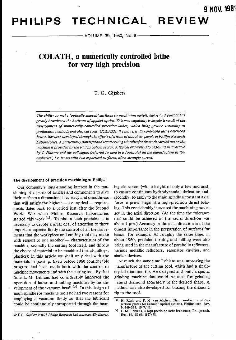
Fig. 1. a) A general view of COLATH, thenumerically controlled precision lathe developed atPhilips Research Laboratories. Left: a computercontrol unit (CNC) with a control panel at the lapcontaining the numerical display units for thepositions of the taalholder and headstock carriages.There is a second control panel on the lathe itself(right); one use of this panel is for accuratelypositioning the tool at the start of a machiningprogram. b) These two bi-aspheric lenses were madeon COLATH. They can be used as an objective in a'VLP' player.
sion improves as the head is brought closer to the disc,but there is then a higher probability that the rapidlyrotating disc and the stationary head might touch andcause damage. The flatness obtained was so good thata compromise distance of about 2 urn could be used.
The surface-machining department also assembleda number of new machines, some of them highlyspecialized, from parts of existing lathes and vacuumheads of various designs. A good example of this isthe much-used spherical-turning machine that canproduce optically smooth spherical surfaces (concaveand convex, maximum diameter about 10 cm).
In the sixties our machines were considerably im-proved as a result of the concentrated study on hydro-static bearings and hydraulic servomotors carried outat that time by the mechanical research group atPhilips Research Laboratories. This research resultedin the design and construction of various new head-stock and carriage arrangements that include very stiffhydraulic bearings and extremely accurate hydraulicdrive systems.
The culmination of all this work came in 1967 and1968 when H. J. J. Kraakman and J. G. C. de Gastdesigned and built a precision lathe [3]. In this newlathe, which was constructed entirely by Philips, allthe bearings are hydrostatic. There is therefore nopossibility of metal-to-metal contact between themoving parts of the lathe. The carriages are driven bylinear hydraulic motors (or 'actuators').
a
A linear hydraulic motor drive has two great advantages: thedrive is direct and exceptionally 'stiff', much stiffer in fact than theconventional mechanical drive; the second advantage is that thedrive mechanism has no periodic structures (such as screw threads).This greatly reduces the possibility of 'ghosts' appearing in themachined surface.
The main spindle is driven by a vane-type motor, arotary hydraulic motor specially designed and con-structed by Philips. The lathe can only be controlledmanually; the speeds at which the carriages can travel(in the direction of the axis of rotation and perpen-dicular to it) are adjusted by means of variable flow-control valves. The form accuracy that can be ob-tained is 1 urn and the surface finish to be achievedcan be described as 'optically smooth'. Kraakmanand De Gast's lathe has proved to be extremelysuitable for geometrically simple work such as turningthe surfaces of cylinders, bushes or planes to a mirrorfinish. The manual control of the carriages does haveits limitations, however. Workpieces of a more com-
Philips tech. Rev. 39, No. 9
plicated shape, like the aspheric lenses now in suchdemand, cannot be machined on this lathe.
In the early seventies we began to think of computercontrol for a precision lathe of this kind instead ofmanual control with its associated limitations. Aprecision lathe of this type with Computer NumericalControl (CNC) was completed and put into serviceduring 1978. The new machine (fig. 1), which wecalled COLATH, allows us to make workpieces ofany arbitrary rotationally symmetric shape. The formaccuracy attainable is better than 0.5 urn for a maxi-mum workpiece diameter of 20 cm. Under favourableconditions the surface roughness is 0.02 urn, which isundoubtedly 'optically smooth'.
The demand for this new precision lathe camemainly from those working in 'optomechanics', arelatively new field in which precision-machiningoperations are used to provide the exceptionally highquality of finish necessary today for optical com-ponents.
Our first experiences with COLATH in such activi-ties were gained in making bi-aspheric plastic lenses.A workpiece of this kind (fig. 1b) usually has tosatisfy the exacting requirement that the natural dif-fraction of the light at the edge of the lens should bethe factor that limits the resolution. Any deviationsfrom the ideal shape of the refracting surfaces of thelens should therefore have less effect. Optical compo-nents that meet this requirement are said to be 'dif-fraction-limited'. The deviations from the ideal lensshape are then so small that the optical path dif-ferences do not exceed iA (Lord Rayleigh, 1878).
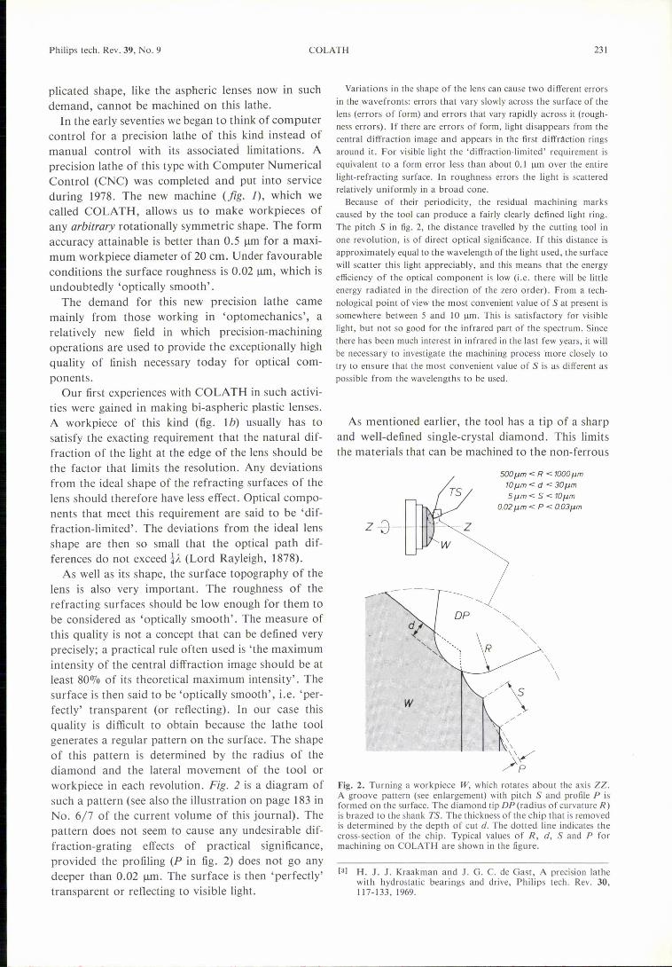
As well as its shape, the surface topography of thelens is also very important. The roughness of therefracting surfaces should be low enough for them tobe considered as 'optically smooth'. The measure ofthis quality is not a concept that can be defined veryprecisely; a practical rule often used is 'the maximumintensity of the central diffraction image should be atleast 80070 of its theoretical maximum intensity'. Thesurface is then said to be 'optically smooth', i.e. 'per-fectly' transparent (or reflecting). In our case thisquality is difficult to obtain because the lathe toolgenerates a regular pattern on the surface. The shapeof this pattern is determined by the radius of thediamond and the lateral movement of the tool orworkpiece in each revolution. Fig. 2 is a diagram ofsuch a pattern (see also the illustration on page 183 inNo. 6/7 of the current volume of this journal). Thepattern does not seem to cause any undesirable dif-fraction-grating effects of practical significance,provided the profiling (P in fig. 2) does not go anydeeper than 0.02 urn. The surface is then 'perfectly'transparent or reflecting to visible light.
COLATH 231
Variations in the shape of the lens can cause two different errorsin the wavefronts: errors that vary slowly across the surface of thelens (errors of form) and errors that vary rapidly across it (rough-ness errors). If there are errors of form, light disappears from thecentral diffraction image and appears in the first diffráction ringsaround it. For visible light the 'diffraction-limited' requirement isequivalent to a form error less than about 0.1 urn over the entirelight-refracting surface. In roughness errors the light is scatteredrelatively uniformly in a broad cone.
Because of their periodicity, the residual machining markscaused by the tool can produce a fairly clearly defined light ring.The pi tch S in fig. 2, the distance travelled by the cutting tool inone revolution, is of direct optical significance. If this distance isapproximately equal to the wavelength of the light used, the surfacewill scatter this light appreciably, and this means that the energyefficiency of the optical component is low (i.e. there will be littleenergy radiated in the direction of the zero order). From a tech-nological point of view the most convenient value of S at present issomewhere between 5 and 10 urn. This is satisfactory for visiblelight, but not so good for the infrared part of the spectrum. Sincethere has been much interest in infrared in the last few years, it willbe necessary to investigate the machining process more closely totry to ensure that the most convenient value of S is as different aspossible from the wavelengths to be used.
As mentioned earlier, the tool has a tip of a sharpand well-defined single-crystal diamond. This limitsthe materials that can be machined to the non-ferrous
500 I'm < R < 1000pmïû urn < d < 3DI'mSpm<S<lOpm
002 I'm < P < 003pm
z
\\\
-, ....-, -,"
w
Fig. 2. Turning a workpiece W, which rotates about the axis ZZ.A groove pattern (see enlargement) with pitch S and profile P isformed on the surface. The diamond tip DP (radius of curvature R)is brazed to the shank TS. The thickness of the chip that is removedis determined by the depth of cut d. The dotted line indicates thecross-section of the chip. Typical values of R, d, Sand P formachining on COLATH are shown in the figure.
[31 H. J. J. Kraakman and J. G. C. de Gast, A precision lathewith hydrostatic bearings and drive, Philips tech. Rev. 30,117-133,1969.
232 T. G. GIJSBERS
metals and their alloys (aluminium, copper, silver,brass, etc.) and the machinable plastics. Iron in thematerial would dissolve traces of carbon from thediamond and this would soon blunt the cutting edge.Furthermore, when a material containing iron is beingmachined, the diamond is liable to crumble, owing to
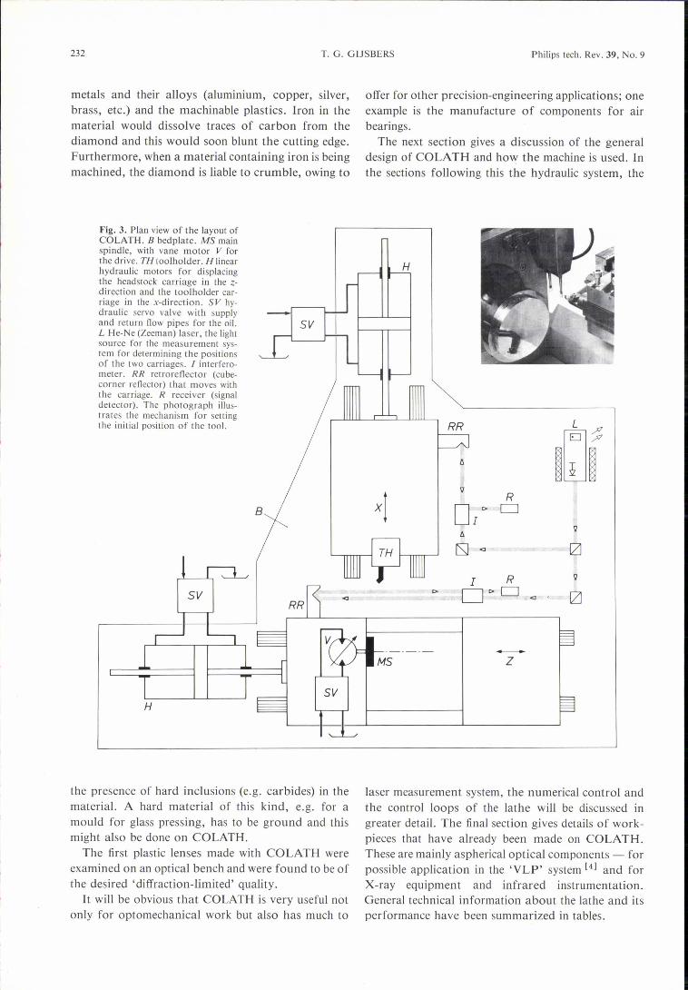
Fig. 3. Plan view of the layout ofCOLATH. B bedplate. MS mainspindle, with vane motor V forthe drive. TH tooiholder. H linearhydraulic motors for displacingthe headstock carriage in the z-direction and the taalholder car-riage in the x-direction. SV hy-draulic servo valve with supplyand return flow pipes for the oil.L He-Ne (Zeeman) laser, the lightsource for the measurement sys-tem for determining the positionsof the two carriages. J interfero-meter. RR re tra reflector (cu be-corner reflector) that moves withthe carriage. R receiver (signaldetector). The photograph illus-trates the mechanism for settingthe initial position of the tool.
Philips tech. Rev. 39, No. 9
offer for other precision-engineering applications; oneexample is the manufacture of components for airbearings.
The next section gives a discussion of the generaldesign of COLATH and how the machine is used. Inthe sections following this the hydraulic system, the
H
t; ~~ixl
'lR
B DI e-0
à'l
[SJ <J !2l
I R 'l
I> Dt> 0 !2l<J •
the presence of hard inclusions (e.g. carbides) in thematerial. A hard materialof this kind, e.g. for amould for glass pressing, has to be ground and thismight also be done on COLATH.
The first plastic lenses made with COLATH wereexamined on an optical bench and were found to be ofthe desired 'diffraction-limited' quality.
It will be obvious that COLATH is very useful notonly for optomechanical work but also has much to
z
laser measurement system, the numerical control andthe control loops of the lathe will be discussed ingreater detail. The final section gives details of work-pieces that have already been made on COLATH.These are mainly as ph erica Ioptical components - forpossible application in the 'VLP' system [4] and forX-ray equipment and infrared instrumentation.General technical information about the lathe and itsperformance have been summarized in tables.

Philips tech. Rev. 39, No. 9
General features of the machine and its use
Design
A plan view of COLATH is shown in fig. 3. Prin-cipal data and performances of the lathe are listed inTable J. As in Kraakman and De Oast's machine [3],
which will be designated simply by its type number(PHMlOOO)from now on, the tooiholder is located ona carriage that can move in the x-direction and theheadstock is mounted on a carriage that can move inthe z-direction. These two structures are mountedindependently of one another on the heavy bedplate ofthe lathe, and because of this have hardly any effecton one another. The headstock carriage is muchIonger than in the PHMI000. This has the advantagethat it is far less easily tilted, since its bearings arefurther apart.Like the PHMI000, COLATH has hydraulic mo-
tors: two linear actuators for moving the two car-riages and a rotary vane mótor to drive the mainspindle. The vane motor is built in as an integral partof the structure of the headstock unit. The motors area little different from those used in the PHMlOOO.The differences, which will be examined in greaterdetail in the next section, have resulted in greaterstiffness of the hydraulic system and consequently afaster response from the control loops.The movements of the carriages in the x- and z-
directions are continuously controlled, in the same
COLATH 233
Table I. Leading technical data and performance of COLATH.
Clamping diameter max. 220 mm
{max. 200 mm diameter (x)max. 200 mm length (z)
1.8-180 mm/rnin1/32-1/16 um/rna"0-1000 rev/ minfree choice<0.5 urnabout 20 nm (peak-to-valley)
Turning dimensions
Carriage velocity (x and z)
Carriage acceleration (x and z)
Speed of main spindleContourForm error [a]
Surface roughness
[a] In theory (ÁX2 + dZ2)!, the distance between a measured pointon the actual contour and the corresponding point on thetheoretical contour.
Both the carriages and the motors have hydrostaticbearings throughout, so that there is no possibility ofany kind of dry friction, the friction that causes thehighly undesirable 'stick-slip' in movement. The self-adjusting couplings between the carriages and thepiston rods of the linear actuators also have hydro-static bearings (this was not so in the PHMI000). Awell-known advantage of hydrostatic bearings com-pared with air bearings is that their stiffness is higher;this clearly is better for machining accuracy [3].
Preparation for turningBefore the automatic execution of a workpiece pro-
gram can be started, the tool tip must be set to aposition accurately known in relation to the axis of
Fig. 4. Block diagram for the control of the displacement of a carriage. Camp computer.ReP required position. MeP measured position. Pas controlled position. The control loopillustrated can be used both for the carriage with the headstock and for the carriage with the tool-holder. D/A digital-to-analog converter. PID electronic controller with proportional, integratingand differentiating action. SV hydraulic control valve. H,X(H,Z) linear actuator with the car-riage for X movement, or the carriage for Z movement, connected to it. M laser interferorneter.FF parallel-input signal, proportional to the velocity of the required displacement.
way but independently of one another, by a CNCunit. The principle of the control system is illustratedin fig. 4 and is the same for both directions. Thishighly sensitive system gives the new lathe essentialadvantages over the old one. It has two laser inter-ferometers that continuously measure the positionsof the carriages (resolution about 16 nm) and feedback the measured data to the comparator unit of theappropriate control circuit.
the machine. This is done by means of a 'mechanicalzero' on the machine (fig. 3). The uncertainty as-sociated with this zero is less than 0.5 urn,The numerical information for turning a workpiece
is processed by means of special computer programsin a separate minicomputer and then transferred to atape. The punched tape can be fed to the CNC unit of
[4] K. Compaan and P. Kramer, The Philips 'VLP' system,Philips tech. Rev. 33, 178-180, 1973.
234 T. G. GUSBERS Philips tech. Rev. 39, No. 9
the machine. When it is preparing the tape the mini-computer takes account of a 'tolerance zone', extrainput data that sets the tolerance limits within whichthe computer program should approximate to thetheoretically desired shapes of the workpiece.
a
\I \~I f3 \
b
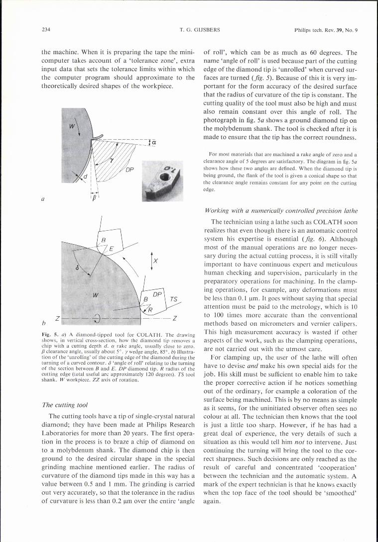
Fig. S. a) A diamond-tipped tool for COLATH. The drawingshows, in vertical cross-section, how the diamond tip removes achip with a cutting depth d. a rake angle, usually close to zero.fJ clearance angle, usually about 5°. Ywedge angle, 85°. b) Illustra-tion of the 'unrolling' of the cutting edge of the diamond during theturning of a curved contour. J 'angle of roll' relating to the turningof the section between Band E. DP diamond tip. R radius of thecutting edge (total useful are approximately 120 degrees). TS toolshank. W workpiece. ZZ axis of rotation.
The cutting tool
The cutting tools have a tip of single-crystal naturaldiamond; they have been made at Philips ResearchLaboratories for more than 20 years. The first opera-tion in the process is to braze a chip of diamond onto a molybdenum shank. The diamond chip is thenground to the desired circular shape in the specialgrinding machine mentioned earlier. The radius ofcurvature of the diamond tips made in this way has avalue between 0.5 and 1 mm. The grinding is carriedout very accurately, so that the tolerance in the radiusof curvature is less than 0.2 urn over the entire 'angle
of roll', which can be as much as 60 degrees. Thename 'angle of roll' is used because part of the cuttingedge of the diamond tip is 'unrolled' when curved sur-faces are turned (fig. 5). Because of this it is very im-portant for the form accuracy of the desired surfacethat the radius of curvature of the tip is constant. Thecutting quality of the tool must also be high and mustalso remain constant over this angle of roll. Thephotograph in fig. Sa shows a ground diamond tip onthe molybdenum shank. The tool is checked after it ismade to ensure that the tip has the correct roundness.
For most materials that are machined a rake angle of zero and aclearance angle of 5 degrees are satisfactory. The diagram in fig. Sashows how these two angles are defined. When the diamond tip isbeing ground, the flank of the tool is given a conical shape so thatthe clearance angle remains constant for any point on the cuttingedge.
Working with a numerically controlled precision lathe
The technician using a lathe such as COLATH soonrealizes that even though there is an automatic controlsystem his expertise is essential (fig. 6). Althoughmost of the manual operations are no longer neces-sary during the actual cutting process, it is still vitallyimportant to have continuous expert and meticuloushuman checking and supervision, particularly in thepreparatory operations for machining. In the clamp-ing operations, for example, any deformations mustbe less than 0.1 urn. It goes without saying that specialattention must be paid to the metrology, which is 10to 100 times more accurate than the conventionalmethods based on micrometers and vernier calipers.This high measurement accuracy is wasted if otheraspects of the work, such as the clamping operations,are not carried out with the utmost care.
For clamping up, the user of the lathe will oftenhave to devise and make his own special aids for thejob. His skill must be sufficient to enable him to takethe proper corrective action if he notices somethingout of the ordinary, for example a coloration of thesurface being machined. This is by no means as simpleas it seems, for the uninitiated observer often sees nocolour at all. The technician then knows that the toolis just a little too sharp. However, if he has had agreat deal of experience, the very details of such asituation as this would tell him not to intervene. Justcontinuing the turning will bring the tool to the cor-rect sharpness. Such decisions are only reached as theresult of careful and concentrated 'cooperation'between the technician and the automatic system. Amark of the expert technician is that he knows exactlywhen the top face of the tool should be 'smoothed'again.

Philips tech. Rev. 39, No. 9
To sum up, machining still requires the greatest careand attention, in spite of the automation, primarilybecause the machining accuracy demanded is so ex-tremely high. Because of the high precision the tech-nician also has to make due allowance for the tem-perature distribution in COLATH; at the least heshould know when the temperature distribution hasbecome stable enough for the machining operationsto be performed with sufficient reproducibility.
In ordinary lathes vibration may occur during thework, with the result that the quality of the finished
IY
Fig. 6. The photograph shows a technician working with COLATH.The small manual control panel on the machine (right) is useful forwork that has to be kept under direct observation.
product is unsatisfactory. The COLATH user shouldbe even more attentive to this; a store of personalknow-how on vibration damping is a great help here.
The handling, cleaning and packaging of the work-pieces are all delicate operations that require a greatdeal of skill and care if the high quality is not to belost.
The hydraulic system also requires the proper atten-tion; it has its own requirements for running in andmaintenance (the oil must be properly de-aerated andthe filters must be cleaned at the correct intervals, forexample). This system does not function independent-ly of other major parts of the equipment, such as thecontrol loops.
The COLATH technician obviously needs to have a
COLATH 235
good general picture of these functional interrelation-ships inside the lathe. He also needs to have a basicunderstanding of the programming methods, sincethe good technician will also want to be able to takeaction here if necessary, either on his own initiative(e.g. to correct the punched tape) or in associationwith the part programmers.If COLATH is to be operated correctly and we are
to take full advantage of all its special features, thenwe need people with a broad technical understandingand a great deal of detailed know-how. They will alsoneed the right sort of disposition and the ability to dothe job 'in cooperation with' an extremely sensitiveand highly automated system - a relatively rare com-bination of man and machine.
The hydraulic system
The hydraulic system of COLATH is illustrated infig. 7. It consists of a pump unit (P) with a reservoir,two linear units (X and Z) for moving the carriages,and a rotary unit (MS) for driving the main spindle,as well as all the hydrostatic bearings (HB) in thevarious units.
The oil supply
The unit P, which contains four independentlyoperating pumps and a cooler, supplies oil to the twolinear actuators (Hl and H2' pump Pl) and the vanemotor (V, pump P2), and also to all the hydrostaticbearings (HB, pump P3). The vane motor has aseparate pump - this was not so in the PHMlOOO -to prevent interaction between the motors Hl' H2 andV. The pump P4 of P pumps the oil through the coolerand back to the reservoir; more will be said about thislater. To keep the temperature of COLATH sufficient-ly constant during operation, considerable coolingcapacity is available - this too will be discussed inmore detail later.
In the oil-supply lines between the pumps and themotors there is an electromagnetically operated con-trol valve (SV). This valve, which is also known as a'servo valve', controls the magnitude of the volumeflow of oil and also, between valve and motor, itsdirection.
The volume flow of the oil is the quantity directly proportional tothe linear speed (or the speed of rotation if appropriate) of a motor(in quasi-static applications). In principle, the control valves SVdetermine all the forward and backward movements of the motors.The speeds are continuously variable about a central position of thevalves; the central position corresponds to a standstill. This type ofcontrol valve, known as a 'throttling directional-control valve', canbe considered as a unit that converts an analog electrical signal intoan analog hydraulic signal.

236 T. G. GUSBERS Philips tech. Rev. 39, No. 9
15---------1IZ
I sv 1
III
I~=j1
I H, IL J
---------j5170bar cûbar
Fig. 7. Diagram of the hydraulic system of COLATH. P pump unit. X linear drive unit formoving the taalholder carriage. Z linear drive unit for moving the headstock carriage. MS rotaryunit for driving the main spindle. HB hydrostatic bearing. SV electromagnetic control valve.HI 2 linear actuator. V vane motor. PI 4 oil pump. M electric motor. PR V pressure-reliefvalve. A accumulator. NRV non-return ~~I·Je.PSV hydraulic switch. F filter. s; 'overflow reser-voir. K water-cooling system. R reservoir. CW cooling water. More information about thehydraulic symbols used in this diagram is given in ISO standard 1219-1976 'Fluid power systemsand components - Graphic symbols' published by the International Organization for Stan-dardization (ISO) and also in the latest edition of the Hydraulic Handbook (published by Tradeand Technical Press, Morden, Surrey, England).
The oil-supply lines contain pressure-relief valves(PR V) to ensure that the operating pressure does notexceed the desired values; they also contain filters (F)to stop the oil from being contaminated. If there is adangerous pressure drop in the supply lines, e.g.because of a leak in the system, the electric motorsthat drive the pumps are automatically switched offby hydraulic switches (PSV).
The undesirable pressure ripples that the pumps PIand P2 might introduce into the system are smoothedout considerably by means of the 'hydraulic accumu-lators' (A). This ensures that the movement of thetwo carriages and the rotation of the main spindle aresufficiently uniform, which is vital to the quality ofthe work that can be done with COLATH. A non-
return valve (NRV) is included in the line to A; thisprevents pump reversal if a pump fails.
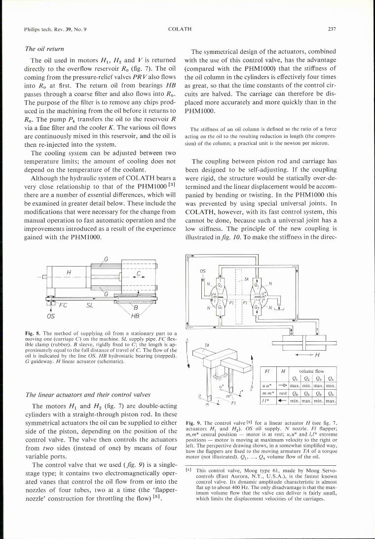
The problem of supplying oil from a stationary partof the machine to a moving one has been solved in anew way in COLATH (fig. 8). The final section of thesupply pipe is supported in a hydrostatic bearing- hence with almost zero friction - in a sleeve rigidlyfixed to the moving part of the machine. The movingsleeve is brought up to operating pressure via an aper-ture in the supply pipe - over the full travel of themoving part. The sleeve can therefore act as a sourceof supply for the moving part of the machine. At itsother end the supply pipe is clamped flexibly (other-wise the structure might be deformed during themovement because of static over-determination).
Philips tech. Rev. 39, No. 9
The oil return
The oil used in motors Hl' H2 and V is returneddirectly to the overflow reservoir Ro (fig. 7). The oilcoming from the pressure-relief valves PR Valso flowsinto R; at first. The return oil from bearings HBpasses through a coarse filter and also flows into Ro.The purpose of the filter is to remove any chips prod-uced in the machining from the oil before it returns toRo. The pump P4 transfers the oil to the reservoir Rvia a fine filter and the cooler K. The various oil flowsare continuously mixed in this reservoir, and the oil isthen re-injected into the system.
The cooling system can be adjusted between twotemperature limits; the amount of cooling does notdepend on the temperature of the coolant.
Although the hydraulic system of COLATH bears avery close relationship to that of the PHMlOOO [3J
there are a number of essential differences, which willbe examined in greater detail below. These include themodifications that were necessary for the change frommanual operation to fast automatic operation and theimprovements introduced as a result of the experiencegained with the PHMlOOO.
G
H
G
SL
os HB
Fig. 8. The method of supplying oil from a stationary part to amoving one (carriage C) on the machine. SL supply pipe. FC flex-ible clamp (rubber). B sleeve, rigidly fixed to C; the length is ap-proximately equal to the full distance of travel of C. The flow of theoil is indicated by the line OS. HB hydrostatic bearing (stepped).G guideway. H linear actuator (schematic).
The linear actuators and their control valves
The motors HI and H2 (fig. 7) are double-actingcylinders with a straight-through piston rod. In thesesymmetrical actuators the oil can be supplied to eitherside of the piston, depending on the position of thecontrol valve. The valve then controls the actuatorsfrom two sides (instead of one) by means of fourvariable ports.
The control valve that we used (fig. 9) is a single-stage type; it contains two electromagnetically oper-ated vanes that control the oil flow from or into thenozzles of four tubes, two at a time (the 'flapper-nozzle' construction for throttling the flow) [5J.
COLATH 237
The symmetrical design of the actuators, combinedwith the use of this control valve, has the advantage(compared with the PHMlOOO) that the stiffness ofthe oil column in the cylinders is effectively four timesas great, so that the time constants of the control cir-cuits are halved. The carriage can therefore be dis-placed more accurately and more quickly than in thePHMlOOO.
The stiffness of an oil column is defined as the ratio of a forceacting on the oil to the resulting reduction in length (the compres-sion) of the column; a practical unit is the newton per micron.
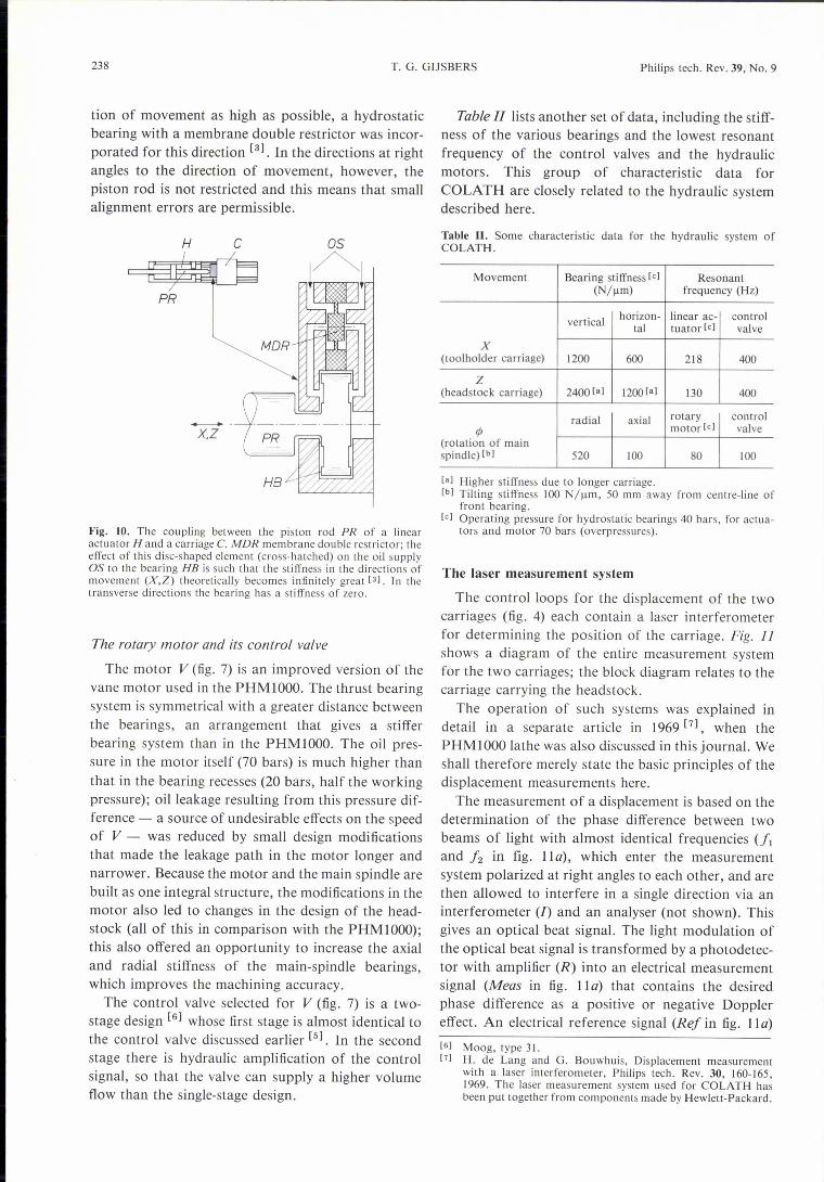
The coupling between piston rod and carriage hasbeen designed to be self-adjusting. If the couplingwere rigid, the structure would be statically over-de-termined and the linear displacement would be accom-panied by bending or twisting. In the PHMlOOO thiswas prevented by using special universal joints. InCOLATH, however, with its fast control system, thiscannot be done, because such a universal joint has alow stiffness. The principle of the new coupling isillustrated infig. 10. To make the stiffness in the direc-
Ft H volume flowQ, Q, Q3 Q,
u u* --t> max. min. max. min.
mm* rest Qo Qo Qo Qo1/* +-- min. max. min. max.
Fig. 9. The control valve [51 for a linear actuator H (see fig. 7,actuators HI and H2). OS oil supply. N nozzle. FI flapper;m.m" central position - motor is at rest; u.u" and /,1· extremepositions - motor is moving at maximum velocity to the right orleft. The perspective drawing shows, in a somewhat simplified way,how the flappers are fixed to the moving armature TA of a torquemotor (not illustrated). Ql' ... , Q, volume flow of the oil.
[51 This control valve, Maag type 61, made by Moog Servo-controls (East Aurora, N.Y., U.S.A.), is the fastest knowncontrol valve. Its dynamic amplitude characteristic is almostflat up to about 400 Hz. The only disadvantage is that the max-imum volume flow that the valve can deliver is fairly small,which limits the displacement velocities of the carriages.
238 T. G. GUSBERS Philips tech. Rev. 39, No. 9
tion of movement as high as possible, a hydrostaticbearing with a membrane double restrictor was incor-porated for this direction [3). In the directions at rightangles to the direction of movement, however, thepiston rod is not restricted and this means that smallalignment errors are permissible.
H
PR
--X,Z
Fig. 10. The coupling between the piston rod PR of a linearactuator H and a carriage C. MDR membrane double restrictor; theeffect of this disc-shaped element (cross-hatched) on the oil supplyOS to the bearing HB is such that the stiffness in the directions ofmovement (X,Z) theoretically becomes infinitely great [31. In thetransverse directions the bearing has a stiffness of zero.
The rotary motor and its control valve
The motor V (fig. 7) is an improved version of thevane motor used in the PHMlOOO. The thrust bearingsystem is symmetrical with a greater distance betweenthe bearings, an arrangement that gives a stifferbearing system than in the PHMIOOO. The oil pres-sure in the motor itself (70 bars) is much higher thanthat in the bearing recesses (20 bars, half the workingpressure); oil leakage resulting from this pressure dif-ference - a source of undesirable effects on the speedof V - was reduced by small design modificationsthat made the leakage path in the motor longer andnarrower. Because the motor and the main spindle arebuilt as one integral structure, the modifications in themotor also led to changes in the design of the head-stock (all of this in comparison with the PHMlOOO);this also offered an opportunity to increase the axialand radial stiffness of the main-spindle bearings,which improves the machining accuracy.
The control valve selected for V (fig. 7) is a two-stage design [6) whose first stage is almost identical tothe control valve discussed earlier [5). In the secondstage there is hydraulic amplification of the controlsignal, so that the valve can supply a higher volumeflow than the single-stage design.
Table 11 lists another set of data, including the stiff-ness of the various bearings and the lowest resonantfrequency of the control valves and the hydraulicmotors. This group of characteristic data forCOLATH are closely related to the hydraulic systemdescribed here.
Table 11. Some characteristic data for the hydraulic system ofCOLATH.
Movement Bearing stiffness [cl Resonant(Nyum) frequency (Hz)
vertical horizon- linear ac- controltal tuator [cl valve
X(toolholder carriage) 1200 600 218 400
Z(headstock carriage) 2400 [al 1200[al 130 400
radial axial rotary controlrjJ motor [cl valve
(rotation of mainspindle) [bI 520 100 80 100
[al Higher stiffness due to longer carriage.[bI Tilting stiffness 100 N/!!m, 50 mm away from centre-line of
front bearing.[cl Operating pressure for hydrostatic bearings 40 bars, for actua-
tors and motor 70 bars (overpressures).
The laser measurement system
The control loops for the displacement of the twocarriages (fig. 4) each contain a laser interferometerfor determining the position of the carriage. Fig. 11shows a diagram of the entire measurement systemfor the two carriages; the block diagram relates to thecarriage carrying the headstock.
The operation of such systems was explained indetail in a separate article in 1969 [7), when thePHMIOOO lathe was also discussed in this journal. Weshall therefore merely state the basic principles of thedisplacement measurements here.
The measurement of a displacement is based on thedetermination of the phase difference between twobeams of light with almost identical frequencies (!1and!2 in fig. IIa), which enter the measurementsystem polarized at right angles to each other, and arethen allowed to interfere in a single direction via aninterferometer (I) and an analyser (not shown). Thisgives an optical beat signal. The light modulation ofthe optical beat signal is transformed by a photodetec-tor with amplifier (R) into an electrical measurementsignal (Meas in fig. 11a) that contains the desiredphase difference as a positive or negative Dopplereffect. An electrical reference signal (Re! in fig. IIa)
[61 Maag, type 3 I.[71 H. de Lang and G. Bouwhuis, Displacement measurement
with a laser interferometer, Philips tech. Rev. 30, 160-165,1969. The laser measurement system used for COLATH hasbeen put together from components made by Hewlett-Packard.

Philips tech. Rev. 39, No. 9 COLATH 239
Fig. 11. The laser measurement system used in COLATH for measuring the carriage displace-ments (Z and X, see also fig. 3). a) Simplified block diagram of the laser measurement system withlinear interferometer (double-beam) for the headstock carriage (Z). A single-beam interferometeris used for the tooiholder carriage. L laser. CL collimator. Ilinear interferometer (double-beam).R receiver, consisting of photodetector and amplifier. RR retroreflector (cube-corner reflector).In the block diagram all the optical signals are indicated by light arrows and the electrical signalsby dark arrows. Posz position of carriage Z. C counter. PC pulse-conversion circuit. PI inter-polation circuit. Meas measurement signal. u up: the pulse is added in C d down: the pulse is sub-tracted in C. 6.1 frequency difference (due to Doppler effect). TR control circuits for stabilizingthe laser frequencies (/1 and 12) and for generating the reference signal Ref. b) The perspectivedrawing shows the system with the two carriages. SM semi-transparent mirror (beam splitter). 11single-beam interferometer. 12 linear interferometer (double-beam). The measurement beams aresurrounded by telescopic tubes (partly shown).
He-NeZeeman
f, - f2 :!: ,U
a
b
without the Doppler effect is derived from the sametwo beams of light before the interferometer. Thephase difference between the two electrical signals iscontinuously compared in the electronic measurementcircuits from the start of the displacement. Wheneverthe displacement changes by an amount equal to Àj 4(À is the wavelength of the laser light in the branchwith the moving mirror RR) the measurement circuitsgenerate a single pulse for a counter. The phase dif-ference has then changed by 180 degrees. Dependingon the sign of the change the pulse is added to, or sub-tracted from, the number of pulses already recorded.The counter therefore indicates the position of the
I
POSZ
carriage at any moment, as derived from a number ofpositive and negative displacements each of magni-tude of 1../4.
The frequencies I1 and 12 are generated by a helium-neon(Zeeman-effect) laser [71. In our case I1 =-12=- 4.7 X 10¹⁴ Hz; theabsolute value of the difference is about 2.3 x 10⁶ Hz. Thebehaviour of the measurement signal as a function of time can bedescribed by an equation of the form sin [2n[(Ji - 12) + 2ii/À! IJ,where ii is the mean displacement velocity of the carriage during theduration I of the displacement. In the case of the reference signalthe phase angle 4niil/ À does not appear in the sine argument. Theterm 2ii/ À, which can be considered as a modification to the differ-ence frequency J; - 12, is the Doppler-effect term.
240 T. G. GIJSBERS Philips tech. Rev. 39, No. 9
The resolution of the laser interferometer can beimproved electronically by another factor of 10. Thisis done with the aid of an interpolation circuit (PI,fig. lla). By applying frequency multiplication to themeasurement signal and the reference signal the inter-polator allows the smallest change in the reading ofthe pulse counter (one pulse) to be made to correspondto a displacement of one-tenth of the displacementequivalent to a phase difference of 180 degrees (Aj4).The resolution of the measurement system is thereforeÀ/40 and this is approximately equal to 16 nm.
The schematic diagram of the arrangement (fig. lIb)shows how the beam from the laser is split by meansof a semi-transparent mirror (SM, beam splitter) intotwo beams at right angles to one another, each withhalf the intensity. The two measurement beams areenclosed in telescopic tubes between the interferom-eter and the moving retroreflector (or 'cube-cornermirror'), to give proteetion from the effect of localcontamination and fluctuations in the density of theair on the beams. (Even the operator's breath mightspoil the quality of the work, because of its highertemperature and higher content of carbon dioxide andwater vapour, if the beams were not isolated from theenvironment.)
To make the system more compact, interferometersof a different type have been used; a single-beam inter-ferometer for the tooiholder carriage, which movesin the x-direction, and a double-beam interferometerfor the carriage that moves in the z-direction.The retroreflectors have the advantage that they
make the interferometer insensitive to small unwantedrotary movements of the carriages. For displacementalong a straight line it is impossible to eliminaterotation completely, however accurately the devicehas been made. The precise orientation of the retro-reflector does not matter much in practice; the inci-dent and reflected beams remain parallel and the totaloptical pathlength travelled does not change - andthis is of course a great advantage when the measure-ment system is being set up.
The measurement unitThe wavelength of the laser light in the measure-
ment beam is the standard on which the unit for theposition measurements (À/40) is based. To keep thisstandard as constant as possible we took three specialprecautions. First of all, the ambient air is carefullyconditioned to stabilize its temperature to within± 0.2 °C. Secondly, the oil in the hydraulic systemcirculates through the entire machine without inter-ruption, while the water-cooling system keeps thetemperature of the oil constant to within a few tenthsof a degree. Thirdly, the machine is kept in operation
continuously (even at night), and as a result there areno longer any significant variations in the tempera-tures of the various parts of the machine.
Our subsequent experience with COLATH suggeststhat these three precautions are sufficient, and thisseems reasonable since the final machining of aproduct only takes a few minutes. Any changes in theambient conditions (moisture content, temperature,pressure) that might have serious consequences cannotarise in such a short time.
A single control pulse is nominally equivalent to a dimensionalunit equal to 1/64 J.UTl, as we shall see in the section on numericalcontrol. This measurement unit is a little smaller than .1./40, theunit corresponding to a single pulse of the measurement signal inthe feedback control loop of the machine. To ensure that anydesired number of control pulses M still results in a workpiecedimension of Mx 1/64 J.UTl, the control program must reduce thenumber M slightly. This is achieved by continuously multiplyingthe control signals by the scale factor 0.98764300. This scale factorcan be determined by a calibration, that is to say by measuring dis-placements on-the machine directly with an independent and cor-rectly calibrated laser interferometer. A better method, but notsuch a fast one, is to proceed as follows. A desired workpiecedimension (ao) is selected more or less at random. This dimension00 divided by 1/64 urn gives a number of control pulses (Mo). Mocontrol pulses are then fed to the control system of the machine, sothat a workpiece, the 'test piece', is produced. If, finally, the actualdimension of the test piece is measured - completely independent-ly of COLATH - and this is then divided into the dimension 00,
then the desired scale factor is obtained. It is of course also possibleto carry out this calibration more than once and for the ultimate inprecision the scale factor is redetermined a number of times.
Numerical control
The main element of the control unit (fig. 1) is aminicomputer (Philips P920l). The numerical-controlsystem also comprises electronic interface circuits andtwo control panels, one on the lathe itself and theother on a control cabinet. The storage capacity of thecomputer is approximately 8000 words of 16 bits andthe cycle time is 0.96 us. This control system is par-ticularly versatile; changes usually only require modi-fications to the software for the computer. The mostimportant advantage of this is that COLATH can stillbe used in the usual way for machining work in theoriginal unchanged program while modifications arebeing carried out.
In the software for COLATH a clear distinction ismade between the P920l control program relating tothe lathe itself and the 'part program'. A part (orworkpiece) program of this kind is prepared 'extern-ally', that is to say on a separate computer and in-dependently of the control unit (we shall return to thislater). It describes only the movements of the lathe(displacements and speeds) that are necessary to make

Philips tech. Rev. 39, No. 9
the particular workpiece, and it is used, in the form ofa punched tape, as input for the control program.The control panel attached to the lathe is mainly for
the operations where a direct view of the workpiece isdesirable; for example positioning the tool with re-spect to the workpiece at the start of a new program.The panel on the control cabinet houses the display
units for the counters (fig. 11) that indicate the posi-tions of the two carriages. A separate display unit canbe used to indicate a third machine function, whichcan be either the speed of the main spindle, thecontour velocity of the tool, or the 'block number',which indicates the part (the program block) beingexecuted on the punched tape containing the work-piece program.The speed of the main spindle can be manually con-
trolled from either panel.
The P9201 control program
The control program ensures that all the instruc-tions that the COLATH operator gives to the com-puter are carried out. The heart of the controlprogram is the 'scheduler', which causes the variouscombinations of the subprograms contained in thecomputer to be started and finished in their variouspriorities. This, of course, requires a communicationsystem that continuously records and releases controldata. In our case use is made of periodic sampling(sampling rate 500 Hz); as a result of this the dataobtained from the lathe is renewed every 2 ms andnew control data is fed to the lathe at the same rate. Inthe intervals in between, Le. preceding each sampling,certain preparations are taking place, such as startingthe available tape reader (again), processing the col-lected data into useful new information, etc.The control program is designed in such a way that
only straight-line movements are performed, and thisis fully compatible with the linear approximationmethod used in the part programming (we shall returnto this in the next section). We aim to extend the con-trol program in due course by adding a facility fornonlinear interpolation, which will approximate thedesired contours by curved line elements. This kind ofinterpolation can lead to better optical performance,e.g. because reflection losses are more uniformlydistributed.
One of the important functions of the control pro-gram is to monitor the contour velocity of the tool.
The contour velocity of the tool is the velocity at which the tip ofthe tool follows the desired contour in the material being turned. Inthe case of COLATH the contour is a curve in the x.z-plane, Thecontour velocity is the vector sum of the displacement velocity ofthe tooihoider carriage and a velocity equal and opposite to that ofthe headstock carriage (fig. 3).
COLATH 241
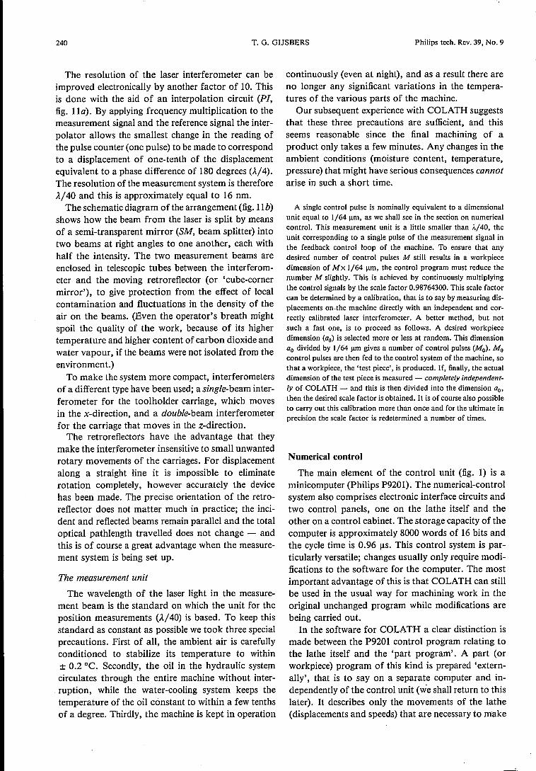
Within each program block the control programselects the velocity in such a way that the deviation inthe final position for the block is as small as possible.The punched tape mentioned before only gives thedesired contour velocity. If for example there is aslight kink in the path to be followed, the control pro-gram adjusts the deceleration to a lower value of thevelocity and adjusts the subsequent acceleration backto the desired contour velocity. The monitoring of thevelocity also ensures that in all circumstances, in-cluding changing from one program block to another,the velocity remains between the minimum and maxi-mum permissible values, and that the movements takeplace as smoothly as possible.The computation unit in the control program has
been taken as 1/128 urn. This was done to allow forany inaccuracies in the computation and to permit theaccuracy of the lathe to be improved at some futuretime if so desired. The computer would then have tobe replaced. In the present situation the control-out-put unit corresponds to 1/64 urn, with the result thatall calculated values have to be halved.
Part programming
A part program is processed on a Philips P856minicomputer, completely independently of any workbeing executed on COLATH; this results in a punchedtape with numerical data for the workpiece. The pro-cessing is mostly done by using special routines writ-ten in FORTRAN, or sometimes with the aid of theprogramming language MICROAPT, derived fromthe APT language [8]. The FORTRAN routines havebeen prepared mainly for making batches of similarworkpieces, Le. a 'workpiece family'. There is forexample a 'universal' program that can be used forgenerating the data for all possible aspherical con-tours.When the punched tape is being prepared, the main
objective is to compute the tool path, the contour thatthe diamond tip has to cut in the material ofthe work-piece. However, this computation process can onlyapproximate the theoretically desired contour of theworkpieces to be turned, and it does this by means ofstraight lines (linear interpolation); the accuracy ofthis approximation depends on the total width of the'tolerance zone' (fig. 12). This value, for example0.1 urn for rough-turning a workpiece and 0.01 urnfor finish-turning, is fed to the P856 beforehand; thismeans that the P856 continues to calculate the path ofthe tool until the path obtained is inside the tolerancezone everywhere. The path data obtained, the x- andz-coordinates of the starting and end points of each[si J. Vlietstra, The APT programming language for the numerical
control of machine tools, Philips tech. Rev. 28, 329-335,1967.
242 T. G. GIJSBERS Philips tech. Rev. 39, No. 9
Fig. 13. Part of the block diagram for the control of the displacement of a carriage (see alsofig. 4). TC clock-pulse generator. BS buffer store. Corn comparator. dB variable attenuator.BA balanced output amplifier. The remaining symbols are explained in the caption to fig. 4.
line element, as well as a number of subsidiary func-tions (contour velocity, stop codes, etc.) are enteredon the punched tape. The punched tape is subdividedinto the program blocks mentioned earlier. Eachblock contains the information for one line element.For a complicated contour with small tolerances thenumber of program blocks can therefore be quitehigh. A plotter connected to the P856 is used to give averification of the punched tape. The tape is then fedto the control unit of the numerical-control system(the P9201) at a speed of 300 characters per second viaan optical 8 channel reader, in portions of severalblocks, while the control program executes the workinstruction block by block.
Control loops
Linear movements
The displacements of the two carriages, in the x-and z-directions, are controlled almost identically.The basic principle of the control procedure has al-ready been discussed in the section on the general
f--------'__j_--__I\ 0A2
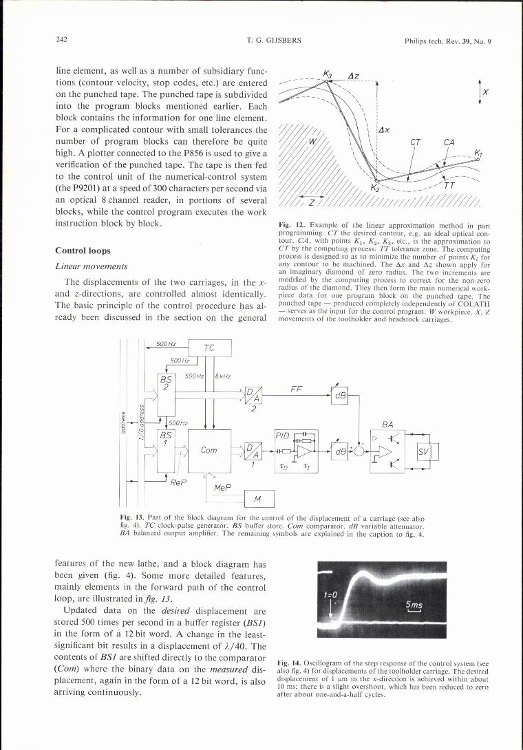
features of the new lathe, and a block diagram hasbeen given (fig. 4). Some more detailed features,mainly elements in the forward path of the controlloop, are illustrated in fig. 13.
Updated data on the desired displacement arestored 500 times per second in a buffer register (BSf)in the form of a 12 bit word. A change in the least-significant bit results in a displacement of À/40. Thecontents of BSI are shifted directly to the comparator(Com) where the binary data on the measured dis-placement, again in the form of a 12 bit word, is alsoarriving continuously.
Fig. 12. Example of the linear approximation method in partprogramming. CT the desired contour, e.g. an ideal optical con-tour. CA, with points KI' K2' K3' etc., is the approximation toCT by the computing process. TT tolerance zone. The computingprocess is designed so as to minimize the number of points K, forany contour to be machined. The Ax and Az shown apply foran imaginary diamond of zero radius. The two increments aremodified by the computing process to correct for the non-zeroradius of the diamond. They then form the main numerical work-piece data for one program block on the punched tape. Thepunched tape - produced completely independently of COLATH- serves as the input for the control program. W workpiece. X, Zmovements of the tooihoider and headstock carriages.
FF
~:---""'-ff _*;;J<
5ms...__..
Fig. 14. Oscillogram of the step response of the control system (seealso fig. 4) for displacements of the tooihoider carriage. The desireddisplacement of I urn in the x-direction is achieved within about10 ms; there is a slight overshoot, which has been reduced to zeroafter about one-and-a-half cycles.

Philips tech. Rev. 39, No. 9
The desired and measured positions are compared16 times in each 2 ms sampling period; the binary dif-ference signal goes to the input of. the digital-to-analog converter D/A 1.
The step instruction being made at the time of sampling - a de-sired carriage displacement, is divided by means of an interpolatorinto 16 equal sub-steps in the ensuing period of 2 ms. This preventsthe control loop from having to react to too large a difference signalat any sampling time.
COLATH 243
Rotary movement
The speed of the main spindle (fig. 3) is continuouslyvariable - up to a maximum of about 1000 revolu-tions per minute - by instructions from the controlcomputer. Feedback from a tachogenerator ensuresthat the speed does not change. Our experience showsthat a simple control system of this kind is adequateprovided that machining is restricted to the turning ofplastics and non-ferrous metals with a diamond-
Fig. IS. Some optical components (and a few others) that have been made on COLATH.
The analog output signal from D / AI, a voltagebetween - 6 and + 6 V, is fed via the electronic con-troller PID, an attenuator, and the output amplifierBA to the hydraulic control valve SV. This valve con-trols the linear actuator (Hl' H2 in fig. 7) and the car-riage connected to it. The controller contains an inte-grating circuit and a differentiating circuit, each withan adjustable time constant (RC time constants T, andTD). This feature allows the behaviour of the controlloop to be improved. To obtain the best possible im-provement - which amongst other things implies thatthe difference between the desired and actual positionsis small enough - a parallel branch has been added tothe forward path of the control loop. This parallelbranch supplies a signal to the output amplifier viaBS2, D / A 2, and an attenuator - a signal that isproportional to the velocity x or i (feedforward).
Fig. 14 illustrates an example of the step responseof the entire system with closed-loop control. Thedynamic behaviour, i.e. the response rate and theovershoot, is entirely acceptable.
tipped tool. In these applications the quality of thework is not affected by the change in the speed thatoccurs as a function of the diameter at which theworkpiece is being machined.
Workpieces
Fig. 15 illustrates a collection of objects that havebeen made with the new lathe. The most importantwork done so far has been the making of bi-asphericlenses, single lenses in which the two refracting sur-faces differ from a true sphere in an extremelyprecisely specified manner. The bi-aspheric lenses canbe characterized as high-grade 'diffraction-limited'optical elements, with additional advantages such assmall size and mass. A design for such a bi-asphericlens is illustrated in fig. 16. This lens is suitable forreading out information in a 'VLP' player [9] that has
[9] J. Haisma, E. Hugues and C. Babolat, Realization of a bi-aspherical objective lens for the Philips Video Long Playsystem, Optics Letters 4,70-72, 1979.

244
a helium-neon laser as the light source (wavelength632.8 nm). Table 111 summarizes the data for thedesired aspherical contours. A batch of 25 lensesbased on this design have already been machined oneafter another on COLATH.
Fig. 16. A design for a bi-aspheric lens, as turned on COLATH.This lens with two aspherical refracting surfaces (RASI,2) issuitable for 'VLP' players with a helium-neon laser as the lightsource. The form error should be no more than 0.2 urn, and thesurface roughness no more than about 20 nm (peak-to-valley). Thediameter of the lens is 8 mm, the maximum length 6.5 ± 0.01 mm.
Interferometric measurements of the quality ofthese lenses have shown that the inaccuracy of eachrefractive surface is only 0.1 to 0.2 urn. One of thelenses has been mounted in a 'VLP' player to find outif the picture information could be read out withoutannoying errors. The results for both stationary andmoving pictures were just as good as those obtainedwith a 'conventional' read-out system containing noless than four sphericallenses.
In the meantime COLATH has also been used toproduce a number of components for use in theoptical recording of X-ray images, e.g. in X-raydiagnostics. These transparent elements, called 'cor-reetion plates', have a flat back and an asphericalfront, Le. they are true correction plates (and notlenses) for certain optical image errors. The geo-metrical tolerance need not be smaller than 0.5 urn;the diameter of the plates we have produced is be-tween 30 and 70 mm.
An optical system for X-ray diagnostic equipment usually hasthree objective lenses: a basic objective that in principle forms animage at infinity of the electronically intensified X-ray picture - forindividual observation, a television objective that produces animage of the X-ray pictures on the sensitive layer of a televisioncamera, and a photographic objective that forms an image so thatthe X-ray picture can be stored on film. By incorporating asphericalcorrection plates the size of these lenses can be kept to a minimum,
COLATH Philips tech. Rev. 39, No. 9
Table Ill. The calculated coefficients of the contour function z(x)for the refracting surfaces of a bi-aspheric lens that can be used fora 'VLP' player. Lens material: polymethyl methacrylate. Lightsource: helium-neon laser, wavelength 632.8 nm.
Coefficient Contour function10
Z = ax2/[1 + [I - (I + b)a2x2Ji] + L Cix2ii=2
(z and x in mm)
I surface 2surface 1
n = 1.4908 at À = 632.8 nm
a +0.240000 -0.51506x 10⁻¹
b -0.29461985 -0.79999995
C2 - 0.23658267 X IO-a + 0.42097500 X 10⁻²
Ca +0.18060664x 10⁻⁶ - 0.81530879 X 10⁻⁴
C4 - 0.38227121 X 10⁻⁶ - 0.60478503 X 10⁻⁶
C6 +0.14036973 X 10⁻⁶ + 0.40506688 X 10⁻⁴
Cs - 0.29596792 X 10⁻⁶ -0.31471338 X 10⁻⁴
C7 + 0.37374523 X 10⁻⁷ +0.13752718 X 10⁻⁴
Cs -0.27752954x IO-s - 0.34047096 X 10⁻⁵
C9 +0.11171180x 10⁻⁹ +0.44607171 X 10⁻⁶
CIO -0.18717534x IO-u - 0.23890333 X 10⁻⁷
whereas the distortion and the field curvature are still sufficientlysmall for the images to remain completely acceptable. One problemis that the machining marks cause extra scattering of the light,reducing the contrast of the image. Studies are continuing to findout how to minimize this scatter.
COLATH has also been used successfully formaking metal mirrors and germanium lenses forinfrared equipment. Here the geometrical precisiondoes not usually have to be much better than 1 urn.
Summary. Description of the construction and characteristics of anumerically controlled precision lathe, COLATH. With a diamond-tipped tool it can be used to machine surfaces of revolution of'optically smooth' (diffraction-limited) quality in non-ferrousmetals and alloys and in plastics. Maximum workpiece dimensionsare 200 mm in diameter (2 x maximum movement of tooiholdercarriage) and 200 mm in length (maximum movement of headstockcarriage); form error is < 0.5 urn, surface roughness (peak-to-valley) is about 20 nm; maximum velocity is 180 mm/ruin (bothcarriages), main-spindle speed 0-1000 rev/min. A minicomputer(P9201) connected to a 2-axis laser measurement system (resolution16 nm) controls the displacements of the carriages by means ofhydraulic servomotors. The main spindle is driven by a hydraulicvane motor, which is integral with it. All the béarings are hydro-static (with oil as the working fluid). The temperatures of theambient air and the oil in the hydraulic system are stabilized. Themeasurement beams of the laser are enclosed in telescopic tubes.The software consists of the P9201 control program and externallyproduced part programs on punched tape. In principle, modifica-tions in the control system only require changes to be made in theP9201 control program. A universal part program ('familyprogram') is available for aspheric lenses. The lathe has been in usesince 1978, and aspheric lenses have now been made for infraredand visible light.

Philips tech. Rev. 39, No. 9
1
Precision fracture of optical glass fibres
In the practical application of opticalglass fibres in telecommunication it isnecessary to be able to break the fibresto give a smooth fracture surfaceaccurate-ly perpendicular to the axis. In the meth-ods that have so far been used the fibre isnicked on one side, by scratching it witha diamond [I] or by heating it with a hotfilament [2], and the two ends are thenpulled apart. It is found that in thesemethods the fracture face is by no meansalways smooth and is generally not trulyperpendicular to the axis of the fibre, asjig. 1 shows for a fibre, with a plastic clad-ding, that has been nicked by a diamond.In a new method [a], in which theseinaccuracies occur much less frequent-ly, the problem is tackled in the follow-ing way. A scratch is made right roundthe fibre with a diamond cutter, and thetwo ends are then pulled apart. Thismethod can be used for all kinds of fibres:
soft glass or fused silica, with a claddingof plastic or glass (usually protected by aplastic coating).
To make the scratch, the cutter, whichrotates around the tensioned fibre, is firstbrought up to speed and slowly moved to-wards the fibre and pressed against it. Thecutter is then pressed against the fibre withthe appropriate force. A perfect scratch isobtained in this way, as jig. 2 shows (theplastic protective coating has been removedhere). The values for the force and speedfor such a result follow from a study of thegrinding of brittle materials [4]. The frac-ture produced on pulling makes an angle ofless than 2° with the normal to the fibre axisand has a perfectly smooth surface. Fig. 3shows this for a completely glass fibre(diameter 100 urn) with a plastic coating,andjig. 4 shows the fracture for a fibre withplastic cladding (total diameter 300 urn). Infig. 4 the track made by the cutter, which
3
has gone through the cladding in a singlerevolution, is clearly evident.
The design and construction of the cut-ting device that gave the results shown hereand the studies that led to its constructionwere carried ou t by a team consisting ofC. J. G. Verwer, Ing. J. C. G. Teunissen,A. J. Luyten, Ing. J. A. Luijendijk, Ing. G.Kuyt, Ir G. D. Khoe, A. J. J. Franken andIng. R. Brehm, all with Philips ResearchLaboratories, Eindhoven.
[IJ D. Gloge, P. W. Smith, D. L. Bisbeeand E. L. Chinnock, Bell Syst. tech. J.52, 1579, 1973.
[2] W. J. J. van Hoppe, G. D. Khoe, G.Kuyt and H. F. G. Smulders, Philipstech. Rev. 37, 89, 1977.
[a] G. D. Khoe, G. Kuyt and J. A. Luijen-dijk, Appl. Optics 20,707, 1981.
[4] A. Broese van Groenou and J. D. B.Veldkamp, Philips tech. Rev. 38, 105,1978/79.
245
2
4