coiltronics high frequency inductor catalog
TRANSCRIPT

Coiltronics®
High Frequency Inductor CatalogMagnetics for Power Management

For product information and data sheets, visit www.cooperbussmann.com/datasheets/elx2
Coiltronics® High Frequency Inductor Catalog
Table of ContentsInductor Series Size (mm) PageFP0705 7 x 7 x 5 4FP0708 7 x 8.5 x 7.2 7FP0805 7.5 x 7.6 x 5 10FP0807 7.4 x 7.6 x 7 13FP1005 7 x 10.2 x 5 16FP1006 8 x 10 x 6 19FP1007 8 x 10.4 x 7 22FP1105 8 x 11 x 5 25FP1107 7.2 x 11 x 7.5 28FP1109 11 x 11 x 9 31FP1308 13 x 13.7 x 9 34FP3 6.7 x 7.2 x 3 37HCP0704 6.8 x 6.8 x 4.2 39HCP0805 7.4 x 7.7 x 5 42
Inductor Solder Profile (all Series) 45
Application NotesHigh Frequency Inductors for Core Power Applications 46Power Inductors Improve Reliability in High Temperature Designs 49Inductor Selection for Switching Regulators 51
Online Resources 55
Leading-Edge TechnologyThe Cooper Bussmann Coiltronics® brand specializes in standard and customsolutions offering the latest in state-of-the-art low-profile high power densitymagnetic components. In working closely with the industry leaders in chipsetand core development, we remain at the forefront of innovation and newtechnology to deliver the optimal mix of packaging, high efficiency andunbeatable reliability. Our designs utilize high frequency, low core loss materials, new and custom core shapes in combination with innovative construction and packaging to provide designers with the highest performance parts available on the market.Market-Driven Products
The Coiltronics brand is the first choice in power inductor and transformersolutions to the ever-changing digital home, office and mobile electronicsworld. In support of this market, we specialize in inductors and transformersfor DC-DC power conversion and switch-mode applications requiring high frequency. Our component solutions can be found in many products requiringpower conversion including cellular telephones, digital cameras, MP3 players,notebook and desktop computers and peripherals and LCD displays acrossthe consumer, communication, computer, industrial and automotive markets.
Standard Products
The Coiltronics brand product line of power magnetics continually expands tosatisfy shifts in technology and related market needs. Categories of StandardProducts include:• High frequency, high current inductors• Shielded drum inductors • Low-profile shielded drum inductors• Unshielded drum inductors • High current inductors• Common-mode inductors • Toroidal inductors• Transformers • Custom magnetics
Custom-Engineered Capabilities• Inductors and transformers for DC-DC converters and off-line switch mode
power supplies (to 200 Watts at voltages up to 450Vac [640Vdc] and frequencies from 20kHz to 10MHz)
• Custom SMT inductors and transformers
Coiltronics products can provide you with custom designs from print throughmanufacture. Our design engineers can take your designated specifications orhelp you determine what the specifications should be. Either way, we’ll getyou the right power magnetic solution to your design challenge.Halogen Free
Cooper Bussmann is committed to meeting the anticipated requirements onthe use of halogens. Currently in place is a Halogen Free Initiative for allCoiltronics® branded inductors and transformers. We are committed to phasing out the use of halogenated materials by the end of calendar year2009. “Halogen free” is defined by homogeneous material per industry standard IPC (IEC 61249-2-21) with the following threshold limits: Chlorine(Cl) <900ppm, Bromine (Br) <900ppm and Chlorine (Cl) + Bromine (Br)<1500ppm.
NEW High Frequency Inductors for Core Power Applications
New in this catalog are 12 Coiltronics® high frequency inductor series with awide range of sizes, current range and DCR tolerance options. They utilizecontrolled DCR tolerance needed for DCR sensing circuits and are well suitedfor capturing the demands of core power and DCR current sensing applications. Their high saturation, low loss and wide temperature range corematerial make them ideally suited for the demands of core power purposes.
Features:• Halogen free• Large variety of shapes and sizes• Ferrite and powder iron core material models available• Controlled DCR for DCR sensing circuits• High current carrying capacity, low core losses• RoHS compliant
Standard Product Families:
FP0705, FP0708, FP0805, FP0807, FP1005, FP1006, FP1007, FP1105,FP1107, FP1109, HCP0704, HCP0805
Cooper Bussmann circuit protection solutions comply with major industrial standards and agency requirements such as: BS, IEC, DIN, UL, NEMA, SAE, CSA, CE, C-UL, etc. and are manufactured at facilities that are ISO 9000 certified.This catalog is intended to present product data and provide technical information that will help the end user with design application. Cooper Bussmann reserves the right, without notice, to change design or construction of any products and todiscontinue or limit distribution of any products. Cooper Bussmann also reserves the right to change or update, without notice, any technical information contained in this catalog. Once a product has been selected, it should be tested by the userin all possible applications. Further, Cooper Bussmann takes no responsibility for errors or omissions contained in this catalog, or for misapplication of any Cooper Bussmann product. Extensive product information is available in the Cooper Bussmannproduct data sheets available online at www.cooperbussmann.com.Printed in USA ©2008 Cooper Bussmann
Magnetics Products for Power Management

For product information and data sheets, visit www.cooperbussmann.com/datasheets/elx 3
Coiltronics® High Frequency Inductor Catalog
FLAT-PAC™ Series
HCP SeriesSolder Profile
Application Notes- Core Pow
erApplication Notes
- High Temp.
Application Notes- Sw
itching
Magnetics Products for Power Management
Shielded Drum Inductors and Low-Profile Shielded DrumInductors
The Coiltronics brand has one of the largest variety of shielded drum coreinductors that utilize a magnetic shield reducing EMI effects and have thebest power density versus size ratio on the market.
Features:• Large variety of shapes and sizes• Maximum power density• Ultra low-profile (as low as 1.0mm in height)• Dual winding: coupled inductor, SEPIC, flyback transformer, 1:1 Isolation
transformer• High current• Magnetic shielding, reduced EMI• Compact footprint
Standard Product Families:
Shielded Drum: DR, DRA, DRQ, DR124, DR1030, DR1040, DR1050,LDS0705.
Low-Profile Shielded Drum:
SD, SDQ, SD3110, SD3112, SD3114, SD3118, SD52, SD53, SD38,SDH3812, SD6020, SD6030, SD7030, SD8328, SD8350.
High Current Inductors
The Coiltronics high current inductor product lines provide an optimal mix ofinnovative packaging, high efficiency and unbeatable reliability.
Features:• Large variety of shapes and sizes• Low-profile (as low as 3mm)• Low DCR, high efficiency• Designed for high current, low voltage applications• Foil construction adds higher reliability factor than traditional magnet wire
used for higher frequency circuits• Gapped ferrite: maximum efficiency, low core loss• High temperature powder iron: 155°C maximum temperature operation,
organic binder eliminates thermal aging
Standard Product Families:
HC1, HC2LP, HC3, HC7, HC8, HC8LP, HC9, HCP0703, HCP1104, HCP1305,HCPT1309, HCF1305, FLAT-PAC™ (FP2), FLAT-PAC™ (FP3),FLAT-PAC™ (FP4), FLAT-PAC™ (FP1308), CPL.
Unshielded Drum Core Inductors
Coiltronics magnetics offer a wide variety of unshielded drum core inductorsin different shapes and sizes to fit all board space constraints.
Features:• Multiple sizes available• Miniature surface mount design• Low-profile• Small footprint• Ferrite core material
Standard Product Families:
UNI-PAC™ (UP1B, 2B, 3B, 4B), UNI-PAC™ 0.4C (UP0.4C), UNI-PAC™ 2.8B(UP2.8B), UNI-PAC™ 2C (UP2C), LD.
Toroid Inductors
Coiltronics® magnetics also offer a mixture of toroid constructed inductorsavailable in surface mount, through hole, and dual winding platforms.
Features:• Surface mount and through-hole mounting• Maximum power density• Dual winding: coupled inductor, SEPIC, flyback transformer, 1:1 isolation
transformer• Low EMI• Variety of core materials: powder iron, MPP, gapped ferrite, amorphous
Standard Product Families:
ECONO-PAC™, OCTA-PAC®, OCTA-PAC® Plus, MICRO-PAC™, MICRO-PAC™ Plus, low cost power inductors (LCPI), current sense (CS).
Common-Mode Inductors
Coiltronics magnetics offers a variety of surface mount and through holeinductors specifically for common-mode circuits.
Features:• Variety of sizes• Surface mount and through hole packages• Wide inductance offering• Ferrite core material
Standard Product Families:
Common mode inductor SMT (CMS), common mode inductor THT (CMT)
Transformers
Coiltronics magnetics also offers a variety of standard transformers thatincrease versatility in design needs.
Features:• Multi-configurable transformer/inductors• Variety of sizes• Multi-configurable power-over-ethernet/PD flyback and forward
transformers• Cold Cathode Fluorescent Lamp (CCFL) Transformers
Standard Product Families:
VERSA-PAC® (VP), VERSA-PAC® high inductance (VPH), Power-over-Ethernet/PD configurable transformer (PoE) flyback and forward, Cold CathodeFluorescent Lamp (CCFL)
Custom Magnetics
Coiltronics magnetics can be customized to meet your application needs. Wespecialize in designing product to specific requirements and new technology,as well as modifying our standard product platforms to meet your requirements.
Modifications to standard products are available.All surface mount components are available in tape-and-reel packaging for pick-and-place utilization.

For product information and data sheets, visit www.cooperbussmann.com/datasheets/elx4
Coiltronics® High Frequency Inductor Catalog
FLAT-PAC™ FP0705 Series
Applications• Portable electronics• Servers and workstations• Data networking and storage systems• Notebook and desktop computers• Graphics cards and battery power systems• Multi-phase regulators• Voltage Regulator Module (VRM)• DCR sensing
Environmental Data• Storage temperature range: -40°C to +125°C• Operating temperature range: -40°C to +125°C
(Range is application specific)• Solder reflow temperature: J-STD-020D compliant
Packaging• Supplied in tape-and-reel packaging, 950 parts per reel,
13” diameter reel
Description• Halogen free• 125°C maximum total temperature operation• 7.0 x 7.0 x 4.95mm surface mount package• Ferrite core material, high current carrying capacity• Low core losses• Controlled DCR tolerance for sensing circuits• Inductance range from 72nH to 220nH• Current range from 20 to 65 amps, frequency range up to 2MHz• RoHS compliant
SMD Device
1 Open Circuit Inductance (OCL) Test Parameters: 100kHz, 0.10Vrms, 0.0Adc
2 Full Load Inductance (FLL) Test Parameters: 100kHz, 0.1Vrms, Isat1
3 Irms: DC current for an approximate temperature rise of 40°C without core loss. Derating is
necessary for AC currents. PCB pad layout, trace thickness and width, air-flow and proximity ofother heat generating components will affect the temperature rise. It is recommended the parttemperature not exceed 125°C under worst case operating conditions verified in the end application.
4 Isat1: Peak current for approximately 20% rolloff at +25°C.
5 Isat2: Peak current for approximately 20% rolloff at +125°C.
6 K-factor: Used to determine Bp-p for core loss (see graph). Bp-p = K * L * ΔI * 10-3, Bp-p : (Gauss),
K: (K-factor from table), L: (inductance in nH), ΔI (peak-to-peak ripple current in amps).7 Part Number Definition: FP0705Rx-Rxx-R
• FP0705 = Product code and size • Rx is the DCR indicator• Rxx= Inductance value in μH, R = decimal point • “-R” suffix = RoHS compliant
Product SpecificationsPart Number OCL1 ± 10% (nH) FLL2 Min. (nH) Irms
3 (Amps) Isat14 @ 25°C (Amps) Isat2
5 @ 125°C (Amps) DCR (mΩ) @ 20°C K-factor6
R1 VersionFP0705R1-R07-R 72 51
43
65 50
0.25 ± 10%
826FP0705R1-R10-R 105 75 44 36 826FP0705R1-R12-R 120 86 37 30 826FP0705R1-R15-R 150 108 30 24 826FP0705R1-R18-R 180 130 25 20 826FP0705R1-R22-R 220 158 20 16 826R2 VersionFP0705R2-R07-R 72 51
38
65 50
0.32 ± 9.4%
826FP0705R2-R10-R 105 75 44 36 826FP0705R2-R12-R 120 86 37 30 826FP0705R2-R15-R 150 108 30 24 826FP0705R2-R18-R 180 130 25 20 826FP0705R2-R22-R 220 158 20 16 826R3 VersionFP0705R3-R07-R 72 51
32
65 50
0.46 ± 6.5%
826FP0705R3-R10-R 105 75 44 36 826FP0705R3-R12-R 120 86 37 30 826FP0705R3-R15-R 150 108 30 24 826FP0705R3-R18-R 180 130 25 20 826FP0705R3-R22-R 220 158 20 16 826

For product information and data sheets, visit www.cooperbussmann.com/datasheets/elx 5
Coiltronics® High Frequency Inductor Catalog
FLAT-PAC™ Series
FLAT-PAC™ FP0705 Series
Dimensions - mm A = 7.0 Max. B = 7.0 Max. C = 4.95 Max. D = 2.45 ± 0.2 E = 1.52 ± 0.2 F = 3.5 Typ.
Top View
a
bB
A
E
D
F
1
2
Rxxwwllyy
Side View Bottom View
2.0
3.1
3.3
Recommended Pad Layout Schematic
1
2
C
0705Rx
R
Section A-AA
A
5.17.1
7.1
User direction of feed
1
2
Section B-BB B
6.5
3.5Rxx
wwllyy
0705Rx
R
16.00 ±0.30
1.5dia.
12.01.5dia
7.5
1.754.02.0
0
20
40
60
80
0.0 0.2 0.4 0.6 0.8 1.0 1.2
Total Loss (W)
Tem
pera
ture
Ris
e (°
C)
Part Marking: Coiltronics Logo 0705Rx (Rx = DCR indicator) Rxx = inductance value in μH (R = decimal point) wwllyy = date code R = revision level
Supplied in tape-and-reel packaging, 950 parts per reel, 13” diameter reel.
Nominal DCR is measured from point “a” to point “b.”
Packaging Information - mm
Temperature Rise vs. Total Loss

For product information and data sheets, visit www.cooperbussmann.com/datasheets/elx6
Coiltronics® High Frequency Inductor Catalog
FLAT-PAC™ FP0705 Series
% of OCL vs. % of I 1
0%
20%
40%
60%
80%
100%
0% 20% 40% 60% 80% 100% 120%% of I 1
% o
f OC
L
+125°C
+25°C
-40°C
sat
sat
Core Loss vs. B
0.00001
0.0001
0.001
0.01
0.1
1
10
100 1000 10000
B (Gauss)
Cor
e Lo
ss(W
)
1MHz
500kHz
300kHz200kHz
100kHz
p-p
p-p
Inductance Characteristics
Core Loss
FLAT-PAC™ FP0708 Series
For product information and data sheets, visit www.cooperbussmann.com/datasheets/elx 7
Coiltronics® High Frequency Inductor Catalog
FLAT-PAC™ Series
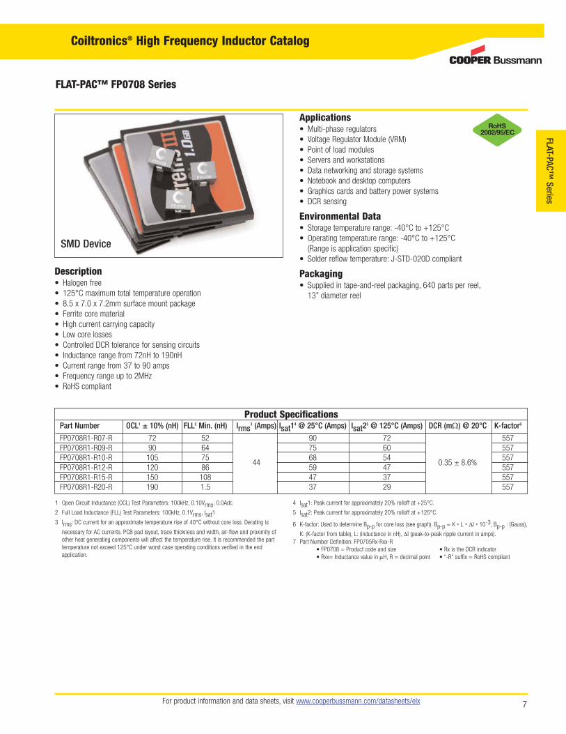
Applications• Multi-phase regulators• Voltage Regulator Module (VRM)• Point of load modules• Servers and workstations• Data networking and storage systems• Notebook and desktop computers• Graphics cards and battery power systems• DCR sensing
Environmental Data• Storage temperature range: -40°C to +125°C• Operating temperature range: -40°C to +125°C
(Range is application specific)• Solder reflow temperature: J-STD-020D compliant
Packaging• Supplied in tape-and-reel packaging, 640 parts per reel,
13” diameter reel
Description• Halogen free• 125°C maximum total temperature operation• 8.5 x 7.0 x 7.2mm surface mount package• Ferrite core material• High current carrying capacity• Low core losses• Controlled DCR tolerance for sensing circuits• Inductance range from 72nH to 190nH• Current range from 37 to 90 amps• Frequency range up to 2MHz• RoHS compliant
SMD Device
1 Open Circuit Inductance (OCL) Test Parameters: 100kHz, 0.10Vrms, 0.0Adc
2 Full Load Inductance (FLL) Test Parameters: 100kHz, 0.1Vrms, Isat1
3 Irms: DC current for an approximate temperature rise of 40°C without core loss. Derating is
necessary for AC currents. PCB pad layout, trace thickness and width, air-flow and proximity ofother heat generating components will affect the temperature rise. It is recommended the parttemperature not exceed 125°C under worst case operating conditions verified in the end application.
4 Isat1: Peak current for approximately 20% rolloff at +25°C.
5 Isat2: Peak current for approximately 20% rolloff at +125°C.
6 K-factor: Used to determine Bp-p for core loss (see graph). Bp-p = K * L * ΔI * 10-3, Bp-p : (Gauss),
K: (K-factor from table), L: (inductance in nH), ΔI (peak-to-peak ripple current in amps).7 Part Number Definition: FP0705Rx-Rxx-R
• FP0708 = Product code and size • Rx is the DCR indicator• Rxx= Inductance value in μH, R = decimal point • “-R” suffix = RoHS compliant
Product SpecificationsPart Number OCL1 ± 10% (nH) FLL2 Min. (nH) Irms
3 (Amps) Isat14 @ 25°C (Amps) Isat2
5 @ 125°C (Amps) DCR (mΩ) @ 20°C K-factor6
FP0708R1-R07-R 72 52
44
90 72
0.35 ± 8.6%
557FP0708R1-R09-R 90 64 75 60 557FP0708R1-R10-R 105 75 68 54 557FP0708R1-R12-R 120 86 59 47 557FP0708R1-R15-R 150 108 47 37 557FP0708R1-R20-R 190 1.5 37 29 557

For product information and data sheets, visit www.cooperbussmann.com/datasheets/elx8
Coiltronics® High Frequency Inductor Catalog
FLAT-PAC™ FP0708 Series
Dimensions - mm A = 7.0 Max. B = 8.5 Max. C = 7.2 Max. D = 2.1 ± 0.15 E = 1.52 ± 0.2 F = 3.6 Typ.
1B
A
2
DE
F
2.5
2.2
3.2
1
2
Top View
0708R1Rxx
wwllyy R
Side View Bottom View Recommended Pad Layout Schematic
C
a
b
Section A-A
A
A
7.3
8.60
7.1
User direction of feed
1
2
Section B-B
B B 6.4
Rxxwwllyy
0708Rx
R
4.50
16.00 ±0.30
1.5dia.
12.01.5dia
7.5
1.754.02.0
0
10
20
30
40
50
60
0.0 0.2 0.4 0.6 0.8 1.0 1.2
Total Loss (W)
Tem
pera
ture
Ris
e (°
C)
Part Marking: Coiltronics Logo 0705Rx (Rx = DCR indicator) Rxx = inductance value in μH (R = decimal point) wwllyy = date code R = revision level
Supplied in tape-and-reel packaging, 640 parts per reel, 13” diameter reel.
Packaging Information - mm
Temperature Rise vs. Total Loss
Nominal DCR is measured from point “a” to point “b.”

FLAT-PAC™ FP0708 Series
For product information and data sheets, visit www.cooperbussmann.com/datasheets/elx 9
Coiltronics® High Frequency Inductor Catalog
FLAT-PAC™ Series
% of OCL vs. % of I 1
0%
20%
40%
60%
80%
100%
0% 20% 40% 60% 80% 100% 120%% of I 1
% o
f OC
L
+125°C
+25°C
-40°C
sat
sat
Core Loss vs. B
0.001
0.01
0.1
1
10
000010001001
B (Gauss)
Cor
e Lo
ss (W
)
1MHz
500kHz
300kHz
200kHz
100kHz
p-p
p-p
Inductance Characteristics
Core Loss

For product information and data sheets, visit www.cooperbussmann.com/datasheets/elx10
Coiltronics® High Frequency Inductor Catalog
FLAT-PAC™ FP0805 Series
Applications• Multi-phase regulators• Voltage Regulator Module (VRM)• Point-of-load modules• Desktop and server VRMs and EVRDs• Data networking and storage systems• Notebook regulators• Graphics cards and battery power systems• DCR sensing
Environmental Data• Storage temperature range: -40°C to +125°C• Operating temperature range: -40°C to +125°C
(Range is application specific)• Solder reflow temperature: J-STD-020D compliant
Packaging• Supplied in tape-and-reel packaging, 950 parts per reel,
13” diameter reel
Description• Halogen free• 125°C maximum total temperature operation• 7.5 x 7.6 x 5mm surface mount package• Ferrite core material• High current carrying capacity, low core losses• Controlled DCR tolerance for sensing circuits• Inductance range from 32nH to 200nH• Current range from 20 to 110 amps• Frequency range up to 2MHz• RoHS compliant
SMD DeviceSMD Device
1 Open Circuit Inductance (OCL) Test Parameters: 100kHz, 0.10Vrms, 0.0Adc
2 Full Load Inductance (FLL) Test Parameters: 100kHz, 0.1Vrms, Isat1
3 Irms: DC current for an approximate temperature rise of 40°C without core loss. Derating is
necessary for AC currents. PCB pad layout, trace thickness and width, air-flow and proximity ofother heat generating components will affect the temperature rise. It is recommended the parttemperature not exceed 125°C under worst case operating conditions verified in the end application.
4 Isat1: Peak current for approximately 20% rolloff at +25°C.
5 Isat2: Peak current for approximately 20% rolloff at +125°C.
6 K-factor: Used to determine Bp-p for core loss (see graph). Bp-p = K * L * ΔI * 10-3, Bp-p : (Gauss),
K: (K-factor from table), L: (inductance in nH), ΔI (peak-to-peak ripple current in amps).7 Part Number Definition: FP0805Rx-Rxx-R
• FP0805 = Product code and size • Rx is the DCR indicator• Rxx= Inductance value in μH, R = decimal point • “-R” suffix = RoHS compliant
Product SpecificationsPart Number7 OCL1 ± 10% (nH) FLL2 Min. (nH) Irms
3 (Amps) Isat14 @ 25°C (Amps) Isat2
5 @ 125°C (Amps) DCR (mΩ) @ 20°C K-factor6
FP0805R1-R03-R 32 23 110 95 823.6FP0805R1-R06-R 58 42 83 61 823.6FP0805R1-R07-R 72 52 65 67 49 0.17 ± 17% 823.6FP0805R1-R10-R 100 72 50 35 823.6FP0805R1-R20-R 200 144 20 16 823.6

FLAT-PAC™ FP0805 Series
For product information and data sheets, visit www.cooperbussmann.com/datasheets/elx 11
Coiltronics® High Frequency Inductor Catalog
FLAT-PAC™ Series
Top View Side View Bottom View Recommended Pad Layout Schematic
1
2
a
b7.49 max
7.62 max
2.16 ±0.2
3.12 ±0.2
3.0 typ.
1
2
Rxxwwllyy R
0805Rx2.79
3.43
5.13
4.96 max
Dimensions - mm
B B
6.80
3.80
Rxxwwllyy
0805Rx
R
16.00±0.30
1.5dia.
12.01.5dia
7.5
1.754.02.0
Section A-A
A
A
5.10 7.727.60
User direction of feed
1
2
Section B-B
Total Loss (W)
Tem
pera
ture
Ris
e (°
C)
50
40
30
20
10
00 0.2 0.4 0.6 0.8 1 1.2 1.4
Part Marking: Coiltronics Logo 0805Rx (Rx = DCR Indicator) Rxx = Inductance value in μH. (R = Decimal point) wwllyy = Date code R = Revision level
The nominal DCR is measured from point “a” to point”b.”
Supplied in tape-and-reel packaging, 950 parts per reel, 13” diameter reel.
Packaging Information - mm
Temperature Rise vs. Total Loss

For product information and data sheets, visit www.cooperbussmann.com/datasheets/elx12
Coiltronics® High Frequency Inductor Catalog
FLAT-PAC™ FP0805 Series
Core Loss vs. B
0.00001
0.0001
0.001
0.01
0.1
1
10
100 1000 10000
B (Gauss)
Cor
e Lo
ss (W
)
1MHz
500kHz300kHz200kH
100kHz
p-p
p-p
% of O C L v s. % of Is a t 1
0%
20%
40%
60%
80%
100%
0% 20% 40% 60% 80% 100% 120%
% of Is a t1
% o
f OC
L
+ 125°C
-40°C
+25°C
Inductance Characteristics
Core Loss

FLAT-PAC™ FP0807 Series
For product information and data sheets, visit www.cooperbussmann.com/datasheets/elx 13
Coiltronics® High Frequency Inductor Catalog
FLAT-PAC™ Series
Applications:• Multi-phase regulators• Voltage Regulator Module (VRM)• Desktop and server VRMs and EVRDs• Notebook regulators• Data networking and storage systems• Graphics cards and battery power systems• Point-of-load modules• DCR sensing
Environmental Data:• Storage temperature range: -40°C to +125°C• Operating temperature range: -40°C to +125°C
(Range is application specific)• Solder reflow temperature: J-STD-020D compliant
Packaging:• Supplied in tape-and-reel packaging, 600 parts per reel,
13” diameter reel
Description:• Halogen free• 125°C maximum total temperature operation• 7.4 x 7.6 x 7.0mm surface mount package• Ferrite core material• High current carrying capacity, low core losses• Controlled DCR tolerance for sensing circuits• Inductance range from 70nH to 220nH• Current range from 35 amps to 108 amps• Frequency range up to 2MHz• RoHS compliant
SMD Device
1 Open Circuit Inductance (OCL) Test Parameters: 100kHz, 0.10Vrms, 0.0Adc
2 Full Load Inductance (FLL) Test Parameters: 100kHz, 0.1Vrms, Isat1
3 Irms: DC current for an approximate temperature rise of 40°C without core loss. Derating is
necessary for AC currents. PCB pad layout, trace thickness and width, air-flow and proximity ofother heat generating components will affect the temperature rise. It is recommended the parttemperature not exceed 125°C under worst case operating conditions verified in the end application.
4 Isat1: Peak current for approximately 20% rolloff at +25°C.
5 Isat2: Peak current for approximately 20% rolloff at +125°C.
6 K-factor: Used to determine Bp-p for core loss (see graph). Bp-p = K * L * ΔI * 10-3, Bp-p : (Gauss),
K: (K-factor from table), L: (inductance in nH), ΔI (peak-to-peak ripple current in amps).7 Part Number Definition: FP0807Rx-Rxx-R
• FP0807 = Product code and size • Rx is the DCR indicator• Rxx= Inductance value in μH, R = decimal point • “-R” suffix = RoHS compliant
Product SpecificationsPart Number7 OCL1 ± 10% (nH) FLL2 Min. (nH) Irms
3 (Amps) Isat14 @ 25°C (Amps) Isat2
5 @ 125°C (Amps) DCR (mΩ) @ 20°C K-factor6
FP0807R1-R07-R 70 50 108 79 520FP0807R1-R10-R 100 72 77 55 520FP0807R1-R12-R 120 86 66 48 520FP0807R1-R16-R 160 115 49 48 36 0.50 ± 6% 520FP0807R1-R18-R 180 129 42 32 520FP0807R1-R20-R 200 144 38 28 520FP0807R1-R22-R 220 158 35 25 520

For product information and data sheets, visit www.cooperbussmann.com/datasheets/elx14
Coiltronics® High Frequency Inductor Catalog
FLAT-PAC™ FP0807 Series
Top V iew Side V iew Bottom V iew Recom m ended Pad Layout Schem atic
1
2
7.0m ax
a
b
2.6
2.62.0
0807RxRxx
wwllyy R
7.6m ax
7.4m ax
1.55±0.2
2.0±0.2
3.3typ.
1
2
1
2
2.7
Dimensions - mm
7.0
1.5 dia.
7.7
9.5
4.02.0
1.5 dia.A
A
1.75
7.516.0±0.3
7.516.0
0807RxRxx
wwllyy R
1
2
Section A-A
User direction of feed
0
10
20
30
40
50
0 0.2 0.4 0.6 0.8 1 1.2 1.4 1.6 1.8 2
T otal Loss (W )
Tem
pera
ture
Ris
e(°C
)
Part Marking: Coiltronics Logo 0807Rx (Rx = DCR Indicator) Rxx = Inductance value in μH. (R = Decimal point) wwllyy = Date code R = Revision level
The nominal DCR is measured from point “a” to point”b.”
Supplied in tape-and-reel packaging, 600 parts per reel, 13” diameter reel.
Packaging Information - mm
Temperature Rise vs. Total Loss

FLAT-PAC™ FP0807 Series
For product information and data sheets, visit www.cooperbussmann.com/datasheets/elx 15
Coiltronics® High Frequency Inductor Catalog
FLAT-PAC™ Series
Core Loss v s . B
0.00001
0.0001
0.001
0.01
0.1
1
10
100 1000 10000
B (Gauss)
Co
re L
oss
(W
)
1M H z
500kH z300kH z200kH z
100kH z
p-p
p-p
% of O CL v s. % of I sa t1
0%
10%
20%
30%
40%
50%
60%
70%
80%
90%
100%
0% 20% 40% 60% 80% 100% 120% 140% 160%
% of I sa t1
% o
f O
CL
+25°C
-40°C
+125°C
Inductance Characteristics
Core Loss

For product information and data sheets, visit www.cooperbussmann.com/datasheets/elx16
Coiltronics® High Frequency Inductor Catalog
FLAT-PAC™ FP1005 Series
Applications• Multi-phase regulators• Voltage Regulator Module (VRM)• Point-of-load modules• Desktop and server VRMs and EVRDs• Data networking and storage systems• Notebook regulators• Graphics cards and battery power systems• DCR sensing
Environmental Data• Storage temperature range: -40°C to +125°C• Operating temperature range: -40°C to +125°C
(Range is application specific)• Solder reflow temperature: J-STD-020D compliant
Packaging• Supplied in tape-and-reel packaging, 950 parts per reel,
13” diameter reel
Description• Halogen free• 125°C maximum total temperature operation• 10.2 x 7.0 x 4.95mm surface mount package• Ferrite core material• High current carrying capacity, low core losses• Controlled DCR tolerance for sensing circuits• Inductance range from 85nH to 220nH• Current range from 33 to 90 amps• Frequency range up to 2MHz• RoHS compliant
SMD Device
1 Open Circuit Inductance (OCL) Test Parameters: 100kHz, 0.10Vrms, 0.0Adc
2 Full Load Inductance (FLL) Test Parameters: 100kHz, 0.1Vrms, Isat1
3 Irms: DC current for an approximate temperature rise of 40°C without core loss. Derating is
necessary for AC currents. PCB pad layout, trace thickness and width, air-flow and proximity ofother heat-generating components will affect the temperature rise. It is recommended the parttemperature not exceed 125°C under worst case operating conditions verified in the end application.
4 Isat1: Peak current for approximately 20% rolloff at +25°C.
5 Isat2: Peak current for approximately 20% rolloff at +125°C.
6 K-factor: Used to determine Bp-p for core loss (see graph). Bp-p = K * L * ΔI * 10-3, Bp-p : (Gauss),
K: (K-factor from table), L: (inductance in nH), ΔI (peak-to-peak ripple current in amps).7 Part Number Definition: FP1005Rx-Rxx-R
• FP1005 = Product code and size • Rx is the DCR indicator• Rxx= Inductance value in μH, R = decimal point • “-R” suffix = RoHS compliant
Product SpecificationsPart Number7 OCL1 ± 10% (nH) FLL2 Min. (nH) Irms
3 (Amps) Isat14 @ 25°C (Amps) Isat2
5 @ 125°C (Amps) DCR (mΩ) @ 20°C K-factor6
R1 VersionFP1005R1-R08-R 85 61 90 64 536FP1005R1-R10-R 100 72 73 57 536FP1005R1-R12-R 120 86 53 60 48 0.39 ± 7.7% 536FP1005R1-R15-R 150 108 47 37 536FP1005R1-R22-R 220 158 33 26 536R2 VersionFP1005R2-R08-R 85 61 90 64 536FP1005R2-R10-R 100 72 73 57 536FP1005R2-R12-R 120 86 50 60 48 0.47 ± 6.7% 536FP1005R2-R15-R 150 108 47 37 536FP1005R2-R22-R 220 158 33 26 536R3 VersionFP1005R3-R08-R 85 61 90 64 536FP1005R3-R10-R 100 72 73 57 536FP1005R3-R12-R 120 86 45 60 48 0.55 ± 5.4% 536FP1005R3-R15-R 150 108 47 37 536FP1005R3-R22-R 220 158 33 26 536

FLAT-PAC™ FP1005 Series
For product information and data sheets, visit www.cooperbussmann.com/datasheets/elx 17
Coiltronics® High Frequency Inductor Catalog
FLAT-PAC™ Series
Dimensions - mm
10.2 max
7.0 max4.95 m ax
2.5 ± 0.2
1.52 ± 0.2
6.5 typ
a
b
1005Rx
wwllyy RRxx
2.0
3.1
6.35
1
2
Top View Side View Bottom View Recommended Pad Layout Schematic
1
2
Section A-A
A
A1.5 dia
1.5 dia4.0
2.0
12.0
1.75
11.5
24.0±0.3
User direction of feed
1
2
wwllyyRxx
1005Rx
R
7.15
10.35
5.1
0
10
20
30
40
50
60
0 0.2 0.4 0.6 0.8 1 1.2 1.4 1.6 1.8 2
Total Loss (W)
Tem
pera
ture
Ris
e (°
C)
Part Marking: Coiltronics Logo 1005Rx (Rx = DCR indicator) Rxx = Inductance value in μH (R = Decimal point) wwllyy = Date code R = Revision level
The nominal DCR is measured from point “a” to point “b.”
Supplied in tape-and-reel packaging, 950 parts per reel, 13” diameter reel.
Packaging Information - mm
Temperature Rise vs. Total Loss

For product information and data sheets, visit www.cooperbussmann.com/datasheets/elx18
Coiltronics® High Frequency Inductor Catalog
FLAT-PAC™ FP1005 Series
Core Loss vs. B
0.00001
0.0001
0.001
0.01
0.1
1
10
000010001001
B (Gauss)
Cor
e Lo
ss (W
)
1MHz500kHz300kHz
200kHz
100kHz
p-p
p-p
% of O C L v s. % of Is a t1
0%
20%
40%
60%
80%
100%
0% 20% 40% 60% 80% 100% 120%
% of Is a t1
% o
f OC
L
+ 125°C
-40°C
+25°C
Inductance Characteristics
Core Loss

For product information and data sheets, visit www.cooperbussmann.com/datasheets/elx 19
Coiltronics® High Frequency Inductor Catalog
FLAT-PAC™ Series
FLAT-PAC™ FP1006 Series
Applications• Multi-phase regulators• Voltage Regulator Module (VRM)• Point-of-load modules• Desktop and server VRMs and EVRDs• Data networking and storage systems• Notebook regulators• Graphics cards and battery power systems• DCR sensing
Environmental Data• Storage temperature range: -40°C to +125°C• Operating temperature range: -40°C to +125°C
(Range is application specific)• Solder reflow temperature: J-STD-020D compliant
Packaging• Supplied in tape-and-reel packaging, 850 parts per reel,
13” diameter reel
Description• Halogen free• 125°C maximum total temperature operation• 10.2 x 8.0 x 6.0mm surface mount package• Ferrite core material• High current carrying capacity, low core losses• Controlled DCR tolerance for sensing circuits• Inductance range from 85nH to 220nH• Current range from 38 to 100 amps• Frequency range up to 2MHz• RoHS compliant
SMD DeviceSMD Device
1 Open Circuit Inductance (OCL) Test Parameters: 100kHz, 0.10Vrms, 0.0Adc
2 Full Load Inductance (FLL) Test Parameters: 100kHz, 0.1Vrms, Isat1
3 Irms: DC current for an approximate temperature rise of 40°C without core loss. Derating is
necessary for AC currents. PCB pad layout, trace thickness and width, air-flow and proximity ofother heat generating components will affect the temperature rise. It is recommended the parttemperature not exceed 125°C under worst case operating conditions verified in the end application.
4 Isat1: Peak current for approximately 20% rolloff at +25°C.
5 Isat2: Peak current for approximately 20% rolloff at +125°C.
6 K-factor: Used to determine Bp-p for core loss (see graph). Bp-p = K * L * ΔI * 10-3, Bp-p : (Gauss),
K: (K-factor from table), L: (inductance in nH), ΔI (peak-to-peak ripple current in amps).7 Part Number Definition: FP1006Rx-Rxx-R
• FP1006 = Product code and size • Rx is the DCR indicator• Rxx= Inductance value in μH, R = decimal point • “-R” suffix = RoHS compliant
Product SpecificationsPart Number7 OCL1 ± 10% (nH) FLL2 Min. (nH) Irms
3 (Amps) Isat14 @ 25°C (Amps) Isat2
5 @ 125°C (Amps) DCR (mΩ) @ 20°C K-factor6
R1 VersionFP1006R1-R08-R 85 61 100 70 454FP1006R1-R10-R 100 72 85 64 454FP1006R1-R12-R 120 86 53 71 53 0.27 ± 12% 454FP1006R1-R16-R 160 115 55 40 454FP1006R1-R22-R 220 158 38 28 454R2 VersionFP1006R2-R08-R 85 61 100 70 454FP1006R2-R10-R 100 72 85 64 454FP1006R2-R12-R 120 86 45 71 53 0.36 ± 8.6% 454FP1006R2-R16-R 160 115 55 40 454FP1006R2-R22-R 220 158 38 28 454

For product information and data sheets, visit www.cooperbussmann.com/datasheets/elx20
Coiltronics® High Frequency Inductor Catalog
FLAT-PAC™ FP1006 Series
Top View Side View Bottom View Recommended Pad Layout Schematic
1
2A 1006Rx
Rxxwwllyy R
8.0 max
6.56
1.92
1.92
a
b3.1
8.0Part NumberFP1006R1-RFP1006R2-R
A max10.210
6.0 max
1
2
2.8 ± 0.1
1.52 ± 0.2
1.52 ± 0.2
6.9 ref
Dimensions - mm
Section A-A
A
A1.5 dia
1.5 dia4.0
2.0
12.0
1.75
11.5
24.0±0.3
User direction of feed
1
2
wwllyyRxx
R
1006Rx
8.1
10.3
6.1
0
10
20
30
40
50
60
0 0.2 0.4 0.6 0.8 1 1.2 1.4
Total Loss (W)
Tem
pera
ture
Ris
e (°
C)
Part Marking: Coiltronics Logo 1006Rx (Rx = DCR Indicator) Rxx = Inductance value in μH. (R = Decimal point) wwllyy = Date code R = Revision level
The nominal DCR is measured from point “a” to point”b.”
Supplied in tape-and-reel packaging, 850 parts per reel, 13” diameter reel.
Packaging Information - mm
Temperature Rise vs. Total Loss

For product information and data sheets, visit www.cooperbussmann.com/datasheets/elx 21
Coiltronics® High Frequency Inductor Catalog
FLAT-PAC™ Series
FLAT-PAC™ FP1006 Series
Core Loss vs. B
0.00001
0.0001
0.001
0.01
0.1
1
10
10,0000001001
B (Gauss)
Cor
e Lo
ss (W
)
1MHz
500kHz300kHz200kHz
100kHz
p-p
p-p
% of O C L v s. % of Is a t 1
0%
20%
40%
60%
80%
100%
0% 20% 40% 60% 80% 100% 120%
% of Is a t1
% o
f OC
L
+125°C
-40°C
+25°C
Inductance Characteristics
Core Loss

For product information and data sheets, visit www.cooperbussmann.com/datasheets/elx22
Coiltronics® High Frequency Inductor Catalog
FLAT-PAC™ FP1007 Series
Applications:• Multi-phase regulators• Voltage Regulator Module (VRM)• Desktop and server VRMs and EVRDs• Notebook regulators• Data networking and storage systems• Graphics cards and battery power systems• Point-of-load modules• DCR sensing
Environmental Data:• Storage temperature range: -40°C to +125°C• Operating temperature range: -40°C to +125°C
(Range is application specific)• Solder reflow temperature: J-STD-020D compliant
Packaging:• Supplied in tape-and-reel packaging on 13” diameter reel• FP1007R1 700 parts per reel• FP1007R2 750 parts per reel
Description:• Halogen free• 125°C maximum total temperature operation• 8.0 x 10.41 x 7.0mm surface mount package• Ferrite core material• High current carrying capacity, low core losses• Controlled DCR tolerance for sensing circuits• Inductance range from 120nH to 300nH• Current range from 32 to 81 amps• Frequency range up to 2MHz• RoHS compliant
SMD DeviceSMD Device
1 Open Circuit Inductance (OCL) Test Parameters: 100kHz, 0.10Vrms, 0.0Adc
2 Full Load Inductance (FLL) Test Parameters: 100kHz, 0.1Vrms, Isat1
3 Irms: DC current for an approximate temperature rise of 40°C without core loss. Derating is
necessary for AC currents. PCB pad layout, trace thickness and width, air-flow and proximity ofother heat generating components will affect the temperature rise. It is recommended the parttemperature not exceed 125°C under worst case operating conditions verified in the end application.
4 Isat1: Peak current for approximately 20% rolloff at +25°C.
5 Isat2: Peak current for approximately 20% rolloff at +125°C.
6 K-factor: Used to determine Bp-p for core loss (see graph). Bp-p = K * L * ΔI * 10-3, Bp-p : (Gauss),
K: (K-factor from table), L: (inductance in nH), ΔI (peak-to-peak ripple current in amps).7 Part Number Definition: FP1007Rx-Rxx-R
• FP1007 = Product code and size • Rx is the DCR indicator• Rxx= Inductance value in μH, R = decimal point • “-R” suffix = RoHS compliant
Product SpecificationsPart Number7 OCL1 ± 10% (nH) FLL2 Min. (nH) Irms
3 (Amps) Isat14 @ 25°C (Amps) Isat2
5 @ 125°C (Amps) DCR (mΩ) @ 20°C K-factor6
R1 VersionFP1007R1-R12-R 120 86 81 65 371FP1007R1-R14-R 140 100 72 56 371FP1007R1-R17-R 170 122 60 58 46 0.29 ± 10% 371FP1007R1-R22-R 215 155 50 36 371FP1007R1-R30-R 300 216 32 26 371R2 VersionFP1007R2-R12-R 120 86 81 65 368FP1007R2-R14-R 140 100 72 56 368FP1007R2-R17-R 170 122 51 58 46 0.48 ± 8% 368FP1007R2-R22-R 215 155 50 36 368FP1007R2-R30-R 300 216 32 26 368

For product information and data sheets, visit www.cooperbussmann.com/datasheets/elx 23
Coiltronics® High Frequency Inductor Catalog
FLAT-PAC™ Series
FLAT-PAC™ FP1007 Series
8.0m ax
Rxxwwllyy R
1007Rx 10.41m ax
2.54±0.20
1
2
2.5 3.0
4.7
a
b
Side V iewBottom V iewTop V iew
2
1
2.24±0.15
Recom m ended Pad Layout Schem atic
1
2
FP1007R1-R = 7.00 max FP1007R2-R = 6.50 max
Dimensions - mm
Section A-A
User direction of feedSection B-B
1.75
11.5
4.0
12.0
1.5 dia. 2.0
24+/-0.310.5
8.1
1.5 dia.
wwllyy RRxx
1007Rx
1
2
FP1007R1 = 7.1FP1007R2 = 6.6
0
10
20
30
40
50
60
0 0.2 0.4 0.6 0.8 1 1.2 1.4 1.6 1.8 2
T otal Loss (W )
Tem
pera
ture
Ris
e (°
C) FP1007R1-R
FP1007R2-R
Part Marking: Coiltronics Logo 1007Rx (Rx = DCR Indicator) Rxx = Inductance value in μH. (R = Decimal point) wwllyy = Date code R = Revision level
The nominal DCR is measured from point “a” to point”b.”
Supplied in tape-and-reel packaging, on 13” diameter reel; FP1007R1 700 parts, FP1007R2 750 parts
Packaging Information - mm
Temperature Rise vs. Total Loss

For product information and data sheets, visit www.cooperbussmann.com/datasheets/elx24
Coiltronics® High Frequency Inductor Catalog
FLAT-PAC™ FP1007 Series
0.00001
0.0001
0.001
0.01
0.1
1
10
100 1000 10000
B (G auss)
Cor
e Lo
ss (
W)
100kHz200kHz300kHz
500kHz1M Hz
p-p
Core Loss vs. Bp-p
% of OCL vs. % of I 1
0%
10%
20%
30%
40%
50%
60%
70%
80%
90%
100%
0% 20% 40% 60% 80% 100% 120%% of I 1
% o
f OC
L
-40°C
+25°C
+125°C
sat
sat
Inductance Characteristics
Core Loss

For product information and data sheets, visit www.cooperbussmann.com/datasheets/elx 25
Coiltronics® High Frequency Inductor Catalog
FLAT-PAC™ Series
FLAT-PAC™ FP1105 Series
Applications• Multi-phase regulators• Voltage Regulator Module (VRM)• Portable electronics• Servers and workstations• Data networking and storage systems• Notebook and desktop computers• Graphics cards and battery power systems• DCR sensing
Environmental Data• Storage temperature range: -40°C to +125°C• Operating temperature range: -40°C to +125°C
(Range is application specific)• Solder reflow temperature: J-STD-020D compliant
Packaging• Supplied in tape-and-reel packaging, 900 parts per reel,
13” diameter reel
Description• Halogen free• 125°C maximum total temperature operation• 11.0 x 8.0 x 4.90mm surface mount package• Ferrite core material• High current carrying capacity• Low core losses• Controlled DCR tolerance for sensing circuits• Inductance range from 101nH to 226nH• Current range from 39 to 81 amps• Frequency range up to 2MHz• RoHS compliant
SMD Device
1 Open Circuit Inductance (OCL) Test Parameters: 100kHz, 0.10Vrms, 0.0Adc
2 Full Load Inductance (FLL) Test Parameters: 100kHz, 0.1Vrms, Isat1
3 Irms: DC current for an approximate temperature rise of 40°C without core loss. Derating is
necessary for AC currents. PCB pad layout, trace thickness and width, air-flow and proximity ofother heat generating components will affect the temperature rise. It is recommended the parttemperature not exceed 125°C under worst case operating conditions verified in the end application.
4 Isat1: Peak current for approximately 20% rolloff at +25°C.
5 Isat2: Peak current for approximately 20% rolloff at +125°C.
6 K-factor: Used to determine Bp-p for core loss (see graph). Bp-p = K * L * ΔI * 10-3, Bp-p : (Gauss),
K: (K-factor from table), L: (inductance in nH), ΔI (peak-to-peak ripple current in amps).7 Part Number Definition: FP1105Rx-Rxx-R
• FP1105 = Product code and size • Rx is the DCR indicator• Rxx= Inductance value in μH, R = decimal point • “-R” suffix = RoHS compliant
Product SpecificationsPart Number OCL1 ± 10% (nH) FLL2 Min. (nH) Irms
3 (Amps) Isat14 @ 25°C (Amps) Isat2
5 @ 125°C (Amps) DCR (mΩ) @ 20°C K-factor6
FP1105R1-R10-R 100 72 81 63 467FP1105R1-R12-R 120 86 66 50 467FP1105R1-R15-R 150 109 46 54 42 0.35 ± 8.6% 467FP1105R1-R20-R 192 138 42 34 467FP1105R1-R22-R 226 163 39 28 467

For product information and data sheets, visit www.cooperbussmann.com/datasheets/elx26
Coiltronics® High Frequency Inductor Catalog
FLAT-PAC™ FP1105 Series
Dimensions - mm A = 11.0 Max. B = 8.0 Max. C = 4.9 Max. D = 2.4 ± 0.2 E = 2.3 ± 0.3 F = 6.2 Typ.
1
2wwllyy
B
A
E
F
Top View Bottom ViewLeft View
2.8
2.85.8
Rxx
1
2 a
b
Recommended Pad Layout Schematic
C D
1105Rx
R
Section A-A
A
A1.5 dia1.5 dia
4.02.0
12.0
1.75
11.524.0
+/-0.3
User direction of feed
1
2
8.2
wwllyyRxx
5.2
11.31105Rx
R
0
10
20
30
40
50
0 0.2 0.4 0.6 0.8 1 1.2 1.4 1.6
Total loss (W)
Tem
pera
ture
rise
(°C
)
Part Marking: Coiltronics Logo 1105Rx (Rx = DCR indicator) Rxx = inductance value in μH (R = decimal point) wwllyy = date code R = revision level
Supplied in tape-and-reel packaging, 900 parts per reel, 13” diameter reel.
Packaging Information - mm
Temperature Rise vs. Total Loss
Nominal DCR is measured from point “a” to point “b.”

FLAT-PAC™ FP1105 Series
For product information and data sheets, visit www.cooperbussmann.com/datasheets/elx 27
Coiltronics® High Frequency Inductor Catalog
FLAT-PAC™ Series
OCL vs. I 1
0%
20%
40%
60%
80%
100%
0% 20% 40% 60% 80% 100% 120%% of I 1
% o
f OC
L
+125°C+25°C
-40°C
sat
sat
Core Loss vs. B
0.0001
0.001
0.01
0.1
1
10
000010001001
B (Gauss)
Cor
e Lo
ss (W
)
1MHz 500kHz
300kHz
200kHz
100kHz
p-p
p-p
Inductance Characteristics
Core Loss

For product information and data sheets, visit www.cooperbussmann.com/datasheets/elx28
Coiltronics® High Frequency Inductor Catalog
FLAT-PAC™ FP1107 Series
Applications:• Multi-phase regulators• Voltage Regulator Module (VRM)• Desktop and server VRMs and EVRDs• Data networking and storage systems• Notebook regulators• Graphics cards and battery power systems• Point-of-load modules• DCR sensing
Environmental Data:• Storage temperature range: -40°C to +125°C• Operating temperature range: -40°C to +125°C
(Range is application specific)• Solder reflow temperature: J-STD-020D compliant
Packaging:• Supplied in tape-and-reel packaging, 640 parts per reel,
13” diameter reel
Description:• Halogen free• 125°C maximum total temperature operation• 7.2 x 11.0 x 7.5mm surface mount package• Ferrite core material• High current carrying capacity, low core losses• Controlled DCR tolerance for sensing circuits• Inductance range from 70nH to 510nH• Current range from 18 to 140 amps• Frequency range up to 2MHz• RoHS compliant
SMD Device
1 Open Circuit Inductance (OCL) Test Parameters: 100kHz, 0.10Vrms, 0.0Adc
2 Full Load Inductance (FLL) Test Parameters: 100kHz, 0.1Vrms, Isat1
3 Irms: DC current for an approximate temperature rise of 40°C without core loss. Derating is
necessary for AC currents. PCB pad layout, trace thickness and width, air-flow and proximity ofother heat generating components will affect the temperature rise. It is recommended the parttemperature not exceed 125°C under worst case operating conditions verified in the end application.
4 Isat1: Peak current for approximately 20% rolloff at +25°C.
5 Isat2: Peak current for approximately 20% rolloff at +125°C.
6 K-factor: Used to determine Bp-p for core loss (see graph). Bp-p = K * L * ΔI * 10-3, Bp-p : (Gauss),
K: (K-factor from table), L: (inductance in nH), ΔI (peak-to-peak ripple current in amps).7 Part Number Definition: FP1107Rx-Rxx-R
• FP1107 = Product code and size • Rx is the DCR indicator• Rxx= Inductance value in μH, R = decimal point • “-R” suffix = RoHS compliant
Product SpecificationsPart Number7 OCL1 ± 10% (nH) FLL2 Min. (nH) Irms
3 (Amps) Isat14 @ 25°C (Amps) Isat2
5 @ 125°C (Amps) DCR (mΩ) @ 20°C K-factor6
R1 VersionFP1107R1-R07-R 70 50 140 123 361.1FP1107R1-R12-R 120 86 90 72 361.1FP1107R1-R15-R 150 108 70 56 361.1FP1107R1-R23-R 230 166 55 45 36 0.29 ± 10% 361.1FP1107R1-R30-R 300 217 35 28 361.1FP1107R1-R40-R 400 288 25 20 361.1FP1107R1-R51-R 510 364 18 14.5 361.1R2 VersionFP1107R2-R07-R 70 50 140 123 363.3FP1107R2-R12-R 120 86 90 72 363.3FP1107R2-R15-R 150 108 70 56 363.3FP1107R2-R23-R 230 166 42 45 36 0.47 ± 6.4% 363.3FP1107R2-R30-R 300 217 35 28 363.3FP1107R2-R40-R 400 288 25 20 363.3FP1107R2-R51-R 510 364 18 14.5 363.3

For product information and data sheets, visit www.cooperbussmann.com/datasheets/elx 29
Coiltronics® High Frequency Inductor Catalog
FLAT-PAC™ Series
FLAT-PAC™ FP1107 Series
Top V iew Side V iew Bottom V iew Recom m ended Pad Layout Schem atic
1
2Rxxwwllyy R
1107Rx
1
2
7.2 m ax
11.0m ax
1.90±0.15
2.5±0.20
5.8 typ
3.1
5.0
2.1
a
bFP1107R1-R = 7.50 FP1107R2-R = 7.20
2
1
Dimensions - mm
Section A-A
User direction of feedSection B-B
1.75
11.5
4.0
12.0
1.5 dia. 2.0
24+/-0.311.1
7.4
1.5 dia.7.6
wwllyy RRxx
1107Rx
1
2
0
20
40
60
80
0.0 0.2 0.4 0.6 0.8 1.0 1.2 1.4 1.6 1.8 2.0 2.2 2.4
T o ta l Loss (W)
Te
mp
era
ture
Ris
e (
°C)
FP1107R 1
FP1107R 2
Part Marking: Coiltronics Logo 1107Rx (Rx = DCR Indicator) Rxx = Inductance value in μH. (R = Decimal point) wwllyy = Date code R = Revision level
The nominal DCR is measured from point “a” to point”b.”
Supplied in tape-and-reel packaging, 640 parts per reel, 13” diameter reel.
Packaging Information - mm
Temperature Rise vs. Total Loss

30 For product information and data sheets, visit www.cooperbussmann.com/datasheets/elx
Coiltronics® High Frequency Inductor Catalog
FLAT-PAC™ FP1107 Series
0 .001
0 .01
0 .1
1
10
100 1000 10000
B (Ga uss)
Co
re L
oss
(W
)
Core Loss vs. B p-p
p-p
1MHz
500kHz
300kHz
200kHz
100kHz
% o f O C L vs % o f Isa t 1
0%
20%
40%
60%
80%
100%
0% 20% 40% 60% 80% 100% 120% 140%
% o f I sa t 1
% o
f OC
L
-40°C
+25°C
+125°C
Inductance Characteristics
Core Loss

For product information and data sheets, visit www.cooperbussmann.com/datasheets/elx 31
Coiltronics® High Frequency Inductor Catalog
FLAT-PAC™ Series
Description:• Halogen free• 125°C maximum total temperature operation• 11.2 x 11.2 x 9.0mm surface mount package• Ferrite core material• High current carrying capacity, low core losses• Controlled DCR tolerance for sensing circuits• Inductance range from 205nH to 950nH• Current range from 11.5 to 69 amps• Frequency range up to 2MHz• RoHS compliant
SMD Device
1 Open Circuit Inductance (OCL) Test Parameters: 100kHz, 0.10Vrms, 0.0Adc
2 Full Load Inductance (FLL) Test Parameters: 100kHz, 0.1Vrms, Isat1
3 Irms: DC current for an approximate temperature rise of 40°C without core loss. Derating is
necessary for AC currents. PCB pad layout, trace thickness and width, air-flow and proximity ofother heat generating components will affect the temperature rise. It is recommended the parttemperature not exceed 125°C under worst case operating conditions verified in the end application.
4 Isat1: Peak current for approximately 30% rolloff at +25°C.
5 Isat2: Peak current for approximately 30% rolloff at +125°C.
6 K-factor: Used to determine Bp-p for core loss (see graph). Bp-p = K * L * ΔI * 10-3, Bp-p : (Gauss),
K: (K-factor from table), L: (inductance in nH), ΔI (peak-to-peak ripple current in amps).7 Part Number Definition: FP1109-xxx-R
• FP1109 = Product code and size• xxx= Inductance value in μH, R = decimal point. If no “R” is present, then
third character = # of zeros• “-R” suffix = RoHS compliant
Product SpecificationsPart Number7 OCL1 ± 10% (nH) FLL2 Min. (nH) Irms
3 (Amps) Isat14 @ 25°C (Amps) Isat2
5 @ 125°C (Amps) DCR (mΩ) @ 20°C K-factor6
FP1109-R20-R 205 122 69 52 233FP1109-R23-R 247 147 55 41 233FP1109-R27-R 270 160 51 38 233FP1109-R33-R 311 185 35 44 33 0.42 ±10% 233FP1109-R47-R 463 275 27 20 233FP1109-R58-R 548 325 22.5 17 233FP1109-1R0-R 950 565 11.5 8.5 233
Applications:• Multi-phase regulators• Voltage Regulator Module (VRM)• Desktop and server VRMs and EVRDs• Data networking and storage systems• Notebook regulators• Graphics cards and battery power systems• Point-of-load modules• DCR sensing
Environmental Data:• Storage temperature range: -40°C to +125°C• Operating temperature range: -40°C to +125°C
(Range is application specific)• Solder reflow temperature: J-STD-020D compliant
Packaging:• Supplied in tape-and-reel packaging, 350 parts per reel,
13” diameter reel
FLAT-PAC™ FP1109 Series

For product information and data sheets, visit www.cooperbussmann.com/datasheets/elx32
Coiltronics® High Frequency Inductor Catalog
Top V iew Side V iew Recom m ended Pad Layout Schem atic
1
2
2.5 nom .(2x)
1
ww
llyy
R
2
FP
11
09
-xxx
3 .0(2X)
3.0(2X)
11.411.2m ax
11.2 m ax
9.0m ax
4.10 ref(2X)2.03 ref
Front V iew
Dimensions - mm
Section A-A
9.3
1.5 dia. +0.1/-0.01.5 dia. min
4.00
2.00
20.00
1.75
11.50
24.0 ±0.3
User direction of feed
11.4
11.4
1
2
16.4
17.5
2.0
FP1109-xxx w
wllyy R
0
10
20
30
40
50
0 0.2 0.4 0.6 0.8 1 1.2 1.4 1.6
T otal Loss (W )
Tem
pera
ture
Ris
e (°
C)
Part Marking: FP1109 xxx = Inductance value in μH. (R = Decimal point). If no “R” is present, then last character is # of zeros wwllyy = Date code R = Revision level
Supplied in tape-and-reel packaging, 350 parts per reel, 13” diameter reel.
Packaging Information - mm
Temperature Rise vs. Total Loss
FLAT-PAC™ FP1109 Series

For product information and data sheets, visit www.cooperbussmann.com/datasheets/elx 33
Coiltronics® High Frequency Inductor Catalog
FLAT-PAC™ Series
C ore Loss vs . B
0.00001
0.0001
0.001
0.01
0.1
1
10
100
10 100 1000
B (G auss)
Co
re L
oss
(W
)
1M Hz
500kHz300kHz200kHz100kHz
p -p
p -p
% o f OC L v s . % o f Is at 1
0%
20%
40%
60%
80%
100%
120%
0% 20% 40% 60% 80% 100% 120%
% o f I 1
+125° C
- 40° C
+25° C
s at
% o
f OC
L
Inductance Characteristics
Core Loss
FLAT-PAC™ FP1109 Series
Coiltronics® High Frequency Inductor Catalog

For product information and data sheets, visit www.cooperbussmann.com/datasheets/elx34
Coiltronics® High Frequency Inductor Catalog
FLAT-PAC™ FP1308 Series
Applications• Voltage regulator modules (VRMs) for servers and
microprocessors• Multi-phase buck inductors• High frequency, high current switching power supplies
Environmental Data• Storage temperature range: -40°C to +125°C• Operating temperature range: -40°C to +125°C
(range is application specific)• Solder reflow temperature: +260°C max. for 10 seconds maximum
Packaging• Supplied in tape-and-reel packaging, 400 parts per 13” diameter reel
Description• 125°C maximum total operating temperature• 12.9 x 13.7 x 8.0mm surface mount package• High current handling capability, compact footprint• Ferrite core material• Inductance range from 0.110μH to 0.440μH• Current range from 32 to 120 amps• Frequency range up to 2MHz
SMD Device
1 Open Circuit Inductance (OCL) Test Parameters: 100kHz, 0.10Vrms, 0.0Adc
2 Irms: DC current for an approximate temperature rise of 40°C without core loss. Derating is
necessary for AC currents. PCB pad layout, trace thickness and width, air-flow and proximity ofother heat generating components will affect the temperature rise. It is recommended the parttemperature not exceed 125°C under worst case operating conditions verified in the end application.
3 Isat: Peak current for approximately 20% rolloff at +25°C.
4 K-factor: Used to determine Bp-p for core loss (see graph). Bp-p = K * L * ΔI. Bp-p (mT):
K: (K-factor from table), L: (inductance in μH), ΔI (peak-to-peak ripple current in amps).5 Part Number Definition: FP1308-xxx-R
• FP1308 = Product code and size• xxx= Inductance value in μH, R = decimal point. If no “R” is present, then
third character = # of zeros.• “-R” suffix = RoHS compliant
Product SpecificationsPart Rated OCL1 Irms
2 Isat3 DCR (mΩ) @ DCR (mΩ) @ K-factor4
Number5 Inductance (μH) ± 10% (μH) (Amps) (Amps) 25°C Typical 25°C MaxFP1308-R11-R 0.110 0.110 68 120 0.20 0.24 21.330FP1308-R21-R 0.210 0.210 68 72 0.20 0.24 21.333FP1308-R26-R 0.260 0.260 68 60 0.20 0.24 21.335FP1308-R32-R 0.320 0.320 68 45 0.20 0.24 21.340FP1308-R44-R 0.440 0.440 68 32 0.20 0.24 21.366

For product information and data sheets, visit www.cooperbussmann.com/datasheets/elx 35
Coiltronics® High Frequency Inductor Catalog
FLAT-PAC™ Series
FLAT-PAC™ FP1308 Series
1
2FP1308-XXXwwllyy R
12.95 max.
13.70 max.
8.0 max.
5.4
2.54 (2plcs)
8.0
7.62
3.18
7.2
1
2
Top View Bottom View Recommended Pad LayoutFront View
Left View
Schematic
Dimensions - mm
2.0
4.0
FP1308-XXX wwllyy R
1.5 dia. +0.1/-0.0
13.9
1.75
24.0 ±0.3
A
13.2
Section A-A
8.2 User direction of feedA
1.5 diia. min
11.5
0
20
40
60
80
100
Total Loss (W)
Tem
pera
ture
Ris
e (°
C)
32.521.510.50
Part Marking: FP1308 xxx = Inductance value in μH. (R = Decimal point). If no “R” is present, then last character is # 0f zeros wwllyy = Date code R = Revision level
Supplied in tape-and-reel packaging, 400 parts per reel, 13” diameter reel.
Packaging Information - mm
Temperature Rise vs. Total Loss
Coiltronics® High Frequency Inductor Catalog

For product information and data sheets, visit www.cooperbussmann.com/datasheets/elx36
Coiltronics® High Frequency Inductor Catalog
FLAT-PAC™ FP1308 Series
Core Loss vs B
0.0001
0.001
0.01
0.1
1
10
0001001011B (mT)
1MHz
500kHz300kHz
100kHz50kHz
Co
reL
os
s(W
)
p-p
p-p
OCL vs I sat
0%
20%
40%
60%
80%
100%
120%
0% 20% 40% 60% 80% 100% 120% 140% 160%
% of Isat
%of
OC
L
+25 °C
-40 °C
+125 °C
Inductance Characteristics
Core Loss

For product information and data sheets, visit www.cooperbussmann.com/datasheets/elx 37
Coiltronics® High Frequency Inductor Catalog
FLAT-PAC™ Series
Product SpecificationsRated OCL 1 Irms 2 Isat 3 Isat 4 DCR
Part Inductance μH ± 15% Amps Amps Amps (mΩ) @ 20°CNumber μH Approx. 10% Approx. 15% (Max.) K-factor 5
FP3-R10-R 0.10 0.10 19.0 27 34.7 1.21 803FP3-R20-R 0.20 0.22 15.3 16 20.8 1.88 482FP3-R47-R 0.47 0.44 10.9 11.6 14.9 3.67 344FP3-R68-R 0.68 0.72 9.72 9.0 11.6 4.63 268FP3-1R0-R 1.00 1.10 6.26 7.4 9.5 11.2 219FP3-1R5-R 1.50 1.50 5.78 6.2 8.0 13.1 185FP3-2R0-R 2.00 2.00 5.40 5.4 6.9 15.0 161FP3-3R3-R 3.30 3.20 3.63 4.3 5.5 30.0 127FP3-4R7-R 4.70 4.70 3.23 3.5 4.2 40.0 105FP3-8R2-R 8.20 8.5 2.91 2.6 3.4 74.0 78FP3-100-R 10.0 10.9 2.30 2.3 3.0 101 69FP3-150-R 15.0 14.9 2.22 2.0 2.5 127 59
Dimensions - mm
Top ViewFront View
7.50
4.50 (2x)
2.50 (2x)
Recommended Pad Layout
2
Schematic
1
3.00 Max
2.80.25(2x)
XXX 7.25Max
6.70Max
yww
2
2.80.25
FP3
(2x) 1
Side View
1.0 min.(2x)
FLAT-PAC™ FP3 Series
Description• 155°C maximum total temperature operation• Low-profile high current inductors• Inductance range 0.1μH to 15μH• Design utilizes high temperature powder iron material with a
non-organic binder to eliminate thermal aging• Current rating up to 34.7Adc (higher peak currents may be attained
with a greater rolloff, see rolloff curve)• Frequency range up to 2MHz
Applications• Computers and portable power devices• Energy storage applications• DC-DC converters• Input - output filter application
Environmental Data• Storage temperature range: -40°C to +155°C• Operating ambient temperature range: -40°C to +155°C
(Range is application specific)• Solder reflow temperature: +260°C max. for 10 seconds max.
Packaging• Units supplied in tape-and-reel packaging,1700 parts per reel,
13” diameter reel
1 OCL (Open Circuit Inductance) Test parameters: 100kHz, 0.1Vrms, 0.0Adc
2 DC current for an approximate ΔT of 40°C without core loss. Derating is necessary for AC currents. PCB layout, trace thickness and width, air-flow, and proximity of other heat generatingcomponents will affect the temperature rise. It is recommended that the temperature of the partnot exceed 155°C under worst case operating conditions verified in the end application.
3 Isat Amps Peak for approximately 10% rolloff @ 20°C
4 Isat Amps Peak for approximately 15% rolloff @ 20°C
5 K-factor: Used to determine Bp-p for core loss (see graph). Bp-p =K*L*³I Bp-p: (Gauss), K: (K
factor from table), L: (Inductance in μH), ΔI (Peak to peak ripple current in Amps).
Coiltronics® High Frequency Inductor Catalog
SMD Device

For product information and data sheets, visit www.cooperbussmann.com/datasheets/elx38
Coiltronics® High Frequency Inductor Catalog
FLAT-PAC™ FP3 Series
OCL vs. I
0102030405060708090
100
0 20 40 60 80 100 120 140 160 180 200
% of I
% o
f OC
L
sat
sat
FP3 AC Loss at Frequency, kH z
Core Loss vs. Flux De ns ity
0.000.10
0.200.30
0.400.500.60
0.700.80
0.901.00
250 500 750 1000 1250 1500 1750 2000 2250
B p -p (Gauss )
Co
reL
os
s (
W)
200
300
400
500
600
700
800
900
1000
0102030405060708090
100110120130140
0.12 0.24 0.36 0.48 0.61 0.73 0.85 0.97 1.09 1.21 1.33 1.45 1.57
Te
mp
era
ture
Ris
e (
°C)
Total Loss (W)
Inductance Characteristics
Core Loss
4.0 2 .0
12.0Ao
Ko
Bo16.0±0.3
7.5
1.75
A
2
1
A
Ao= 6.6mmBo= 7.1mmKo= 3.2mm
0.3 Radmax.
1.5 Diamin.
0.30±0.05
1.5 Dia+0.1/-0.0
0.5 Radtyp.
Direction of feed
Section A-A
Packaging Information - mm
xxx = Inductance value yww = Date code
Temperature Rise vs. Total Loss

For product information and data sheets, visit www.cooperbussmann.com/datasheets/elx 39
Coiltronics® High Frequency Inductor Catalog
HCP Series
HCP0704 Series
Applications:• Voltage Regulator Module (VRM) • Multi-phase regulators• Desktop and servers• Base station equipment• Notebook regulators• Data networking and storage systems• Point-of-load modules• Battery power systems• DCR sensing
Environmental Data:• Storage temperature range: -40°C to +155°C• Operating temperature range: -40°C to +155°C
(Range is application specific)• Solder reflow temperature: J-STD-020D compliant
Packaging:• Supplied in tape-and-reel packaging, 1000 parts per reel,
13” diameter reel
Description:• Halogen free• 155°C maximum total temperature operation• 6.8 x 6.8 x 4.2mm surface mount package• Powder iron core material• Magnetically shielded, low EMI• High temperature core material eliminates thermal aging issues• High current carrying capacity, low core losses• Controlled DCR tolerance for sensing circuits• Inductance range from 0.40μH to 4.7μH• Current range from 5.0 to 27 amps• Frequency range up to 2MHz• RoHS compliant
SMD Device
1 Open Circuit Inductance (OCL) Test Parameters: 100kHz, 0.10Vrms, 0.0Adc
2 Full Load Inductance (FLL) Test Parameters: 100kHz, 0.1Vrms, Isat1
3 Irms: DC current for an approximate temperature rise of 40°C without core loss. Derating is
necessary for AC currents. PCB pad layout, trace thickness and width, air-flow and proximity ofother heat generating components will affect the temperature rise. It is recommended the parttemperature not exceed 125°C under worst case operating conditions verified in the end application.
4 Isat: Peak current for approximately 20% rolloff at +25°C.
5 K-factor: Used to determine Bp-p for core loss (see graph). Bp-p = K * L * ΔI : (Gauss), K: (K-factor
from table), L: (inductance in μH), ΔI (peak-to-peak ripple current in amps).6 Part Number Definition: HCP0704-xxx-R
• HCP0704 = Product code and size• xxx= Inductance value in μH, R = decimal point. If no “R” is present, then
third character = # of zeros• “-R” suffix = RoHS compliant
Product SpecificationsPart Number6 OCL1 ± 25% (μH) FLL2 Min. (μH) Irms
3 (Amps) Isat4 @ 25°C (Amps) DCR (mΩ) @ 20°C K-factor5
HCP0704-R40-R 0.40 0.28 17 27 3.2 ±10% 383.1HCP0704-R60-R 0.50 0.42 14 21 4.5 ±10% 313.5HCP0704-1R0-R 1.00 0.7 12 17 6.2 ±10% 265.3HCP0704-1R8-R 1.80 1.26 8.5 13 11.0 ±10% 202.8HCP0704-2R3-R 2.30 1.56 7.5 11.5 16.5 ±10% 164.2HCP0704-3R3-R 3.30 2.31 6.0 9.5 25.0 ±10% 149.9HCP0704-4R7-R 4.70 3.29 5.0 8.0 29.5 ±10% 127.7
Coiltronics® High Frequency Inductor Catalog

For product information and data sheets, visit www.cooperbussmann.com/datasheets/elx40
Coiltronics® High Frequency Inductor Catalog
HCP0704 Series
Top V iew Side V iew Bottom View Recom m ended Pad Layout Schem atic
1
21 2
H
CP
07
04
ww
llyy
R
6 .80 M ax
6.80 M ax
3.3±0.3
HCP0704-R40 to 2R3= 1.20 +/- 0.2HCP0704-3R3 to 4R7= 1.00 +/- 0.2
xx
x
HCP0704-R40 to 1R0= 4.20 m axHCP0704-1R8 to 4R7= 4.00 m ax
7.60
2.50(2x)
4.00(2x)2 1
Dimensions - mm
User direction of feedHCP0704-R40 to 1R0= 4.2HCP0704-1R8 to 4R7= 4.0
Section A-A
1.5 Diamin.
7.50
6.912.0
4.02.0
1.5 Dia.+0.1/-0.0
A
A
1.75
7.516.0±0.3
1
2
HCP0704
wwllyy Rxxx
0
10
20
30
40
50
60
0 0.2 0.4 0.6 0.8 1 1.2 1.4
Tota l Los s (W)
Tem
peta
ture
Ris
e(° C
)
Part Marking: HCP0704 xxx = Inductance value in μH. (R = Decimal point). If no “R” is present, then last character is # of zeros wwllyy = Date code R = Revision level
The nominal DCR test point is in the middle of the terminal
Supplied in tape-and-reel packaging, 1000 parts per reel, 13” diameter reel.
Packaging Information - mm
Temperature Rise vs. Total Loss

For product information and data sheets, visit www.cooperbussmann.com/datasheets/elx 41
Coiltronics® High Frequency Inductor Catalog
HCP Series
HCP0704 Series
0. 001
0. 01
0. 1
1
10
10 100 1000 10000
Co
re L
os
s (
W)
1 MHz 2 5 0 kHz
1 0 0 kHz5 0 0 kHzCore Los s v s . Bp-p
B (G aus s )p-p
% of O CL v s % of I
0%
20%
40%
60%
80%
100%
0% 20% 40% 60% 80% 100% 120% 140% 160%
% of I
% o
f OC
L
25°C
sat
sat
Inductance Characteristics
Core Loss
Coiltronics® High Frequency Inductor Catalog

For product information and data sheets, visit www.cooperbussmann.com/datasheets/elx42
Coiltronics® High Frequency Inductor Catalog
HCP0805 Series
Applications:• Voltage Regulator Module (VRM) • Multi-phase regulators• Desktop and servers• Base station equipment• Notebook regulators• Data networking and storage systems• Point-of-load modules• Battery power systems• DCR sensing
Environmental Data:• Storage temperature range: -40°C to +125°C• Operating temperature range: -40°C to +125°C
(Range is application specific)• Solder reflow temperature: J-STD-020D compliant
Packaging:• Supplied in tape-and-reel packaging, 700 parts per13” diameter reel
Description:• Halogen free• 125°C maximum total temperature operation• 7.6 x 7.9 x 5.0mm surface mount package• Powder iron core material• Magnetically shielded, low EMI• High current carrying capacity, low core losses• Controlled DCR tolerance for sensing circuits• Inductance range from 0.40μH to 2.2μH• Current range from 10.0 to 32 amps• Frequency range up to 2MHz• RoHS compliant
SMD Device
1 Open Circuit Inductance (OCL) Test Parameters: 100kHz, 0.10Vrms, 0.0Adc
2 Full Load Inductance (FLL) Test Parameters: 100kHz, 0.1Vrms, Isat1
3 Irms: DC current for an approximate temperature rise of 40°C without core loss. Derating is
necessary for AC currents. PCB pad layout, trace thickness and width, air-flow and proximity ofother heat generating components will affect the temperature rise. It is recommended the parttemperature not exceed 125°C under worst case operating conditions verified in the end application.
4 Isat: Peak current for approximately 20% rolloff at +25°C.
5 K-factor: Used to determine Bp-p for core loss (see graph). Bp-p = K * L * ΔI. Bp-p : (Gauss), K:
(K-factor from table), L: (inductance in μH), ΔI (peak-to-peak ripple current in amps).6 Part Number Definition: HCP0805-xxx-R
• HCP0805 = Product code and size• xxx= Inductance value in μH, R = decimal point. If no “R” is present, then
third character = # of zeros.• “-R” suffix = RoHS compliant
Product SpecificationsPart Number6 OCL1 ± 20% (μH) FLL2 Min. (μH) Irms
3 (Amps) Isat4 @ 25°C (Amps) DCR (mΩ) @ 20°C K-factor5
HCP0805-R40-R 0.40 0.26 20 32 3.1 ±6.0% 376.0HCP0805-R68-R 0.68 0.44 17.5 25 4.5 ±6.0% 292.0HCP0805-1R0-R 1.00 0.64 14.5 22 5.8 ±6.0% 239.0HCP0805-1R5-R 1.50 0.96 13.3 18 6.8 ±6.0% 202.0HCP0805-2R2-R 2.20 1.41 10 14 11.2 ±6.0% 175.0

For product information and data sheets, visit www.cooperbussmann.com/datasheets/elx 43
Coiltronics® High Frequency Inductor Catalog
HCP Series
HCP0805 Series
Top V iew Side V iew Bottom V iew Recom m ended Pad Layout Schem atic
1
2XXX
1
HCP0805
wwllyy R
7.70 ± 0.20
5.0 m ax
7.40 ± 0.20
b
a
E(2x)
4.3 typ.
1.70 ± 0.30
1
22
3.50
8.1
1.8(2x)
P in w idth Part No.
HCP0805-R40-R 1.3 ±0.2HCP0805-R68-R 1.1 ±0.2
HCP0805-1R0-R 1.1 ±0.2
HCP0805-1R5-R 1.1 ±0.2
HCP0805-2R2-R 0.8 ±0.2
E (m m )
Dimensions - mm
User direction of feed5.2
Section A-A
1.5 Diamin.
7.816.0
4.02.0
1.5 Dia.+0.1/-0.0
A
A
1.75
7.516.0± 0.3
1
2
8.1 HCP0805
wwllyy RXXX
0
10
20
30
40
50
60
0 0.2 0.4 0.6 0.8 1 1.2
Tota l Los s (W)
Te
mpe
ratu
re R
ise
(°C
)
Part Marking: HCP0805 xxx = Inductance value in μH. (R = Decimal point). If no “R” is present, then last character is # 0f zeros wwllyy = Date code R = Revision level
The nominal DCR is measured from point “a” to point”b.”
Supplied in tape-and-reel packaging, 700 parts per reel, 13” diameter reel.
Packaging Information - mm
Temperature Rise vs. Total Loss
Coiltronics® High Frequency Inductor Catalog

For product information and data sheets, visit www.cooperbussmann.com/datasheets/elx44
Coiltronics® High Frequency Inductor Catalog
HCP0805 Series
Core Loss vs. B
1 0 0 k Hz
2 0 0 k Hz3 0 0 k Hz
5 0 0 k Hz
1 MHz
0.001
0.01
0.1
1
10
100
100 1000 10000
B (Gua ss)
Co
re L
oss
(W
)
p -p
p-p
% of OCL vs. % of I
0%
10%
20%
30%
40%
50%
60%
70%
80%
90%
100%
110%
0% 20% 40% 60% 80% 100% 120% 140% 160% 180% 200%
% of I
% o
f O
CL
sat
sat
Inductance Characteristics
Core Loss

For product information and data sheets, visit www.cooperbussmann.com/datasheets/elx 45
Coiltronics® High Frequency Inductor Catalog
Solder Profile
Solder Reflow Profile for FLAT-PAC™ FP Series and HCP Series Inductors
Solder Reflow Profile
Temperature
t
tP
ts
TC -5°C
Time 25°C to Peak Time25°C
Tsmin
Tsmax
TL
TP
Preheat A
Max. Ramp Up Rate = 3°C/sMax. Ramp Down Rate = 6°C/s
TTaabbllee 11 -- SSttaannddaarrdd SSnnPPbb SSoollddeerr ((TTcc))
Volume VolumePackage mm3 mm3
Thickness <350 >_350<2.5mm 235°C 220°C>_2.5mm 220°C 220°C
TTaabbllee 22 -- LLeeaadd ((PPbb)) FFrreeee SSoollddeerr ((TTcc))
Volume Volume VolumePackage mm3 mm3 mm3
Thickness <350 350 - 2000 >2000<1.6mm 260°C 260°C 260°C1.6 – 2.5mm 260°C 250°C 245°C>2.5mm 250°C 245°C 245°C
Reference JDEC J-STD-020DProfile Feature Standard SnPb Solder Lead (Pb) Free SolderPreheat and Soak • Temperature min. (Tsmin) 100°C 150°C
• Temperature max. (Tsmax) 150°C 200°C
• Time (Tsmin to Tsmax) (ts) 60-120 Seconds 60-120 Seconds
Average ramp up rate Tsmax to Tp 3°C/ Second Max. 3°C/ Second Max.
Liquidous temperature (TL) 183°C 217°CTime at liquidous (tL) 60-150 Seconds 60-150 Seconds
Peak package body temperature (TP)* Table 1 Table 2
Time (tp)** within 5 °C of the specified classification temperature (Tc) 20 Seconds** 30 Seconds**
Average ramp-down rate (Tp to Tsmax) 6°C/ Second Max. 6°C/ Second Max.
Time 25°C to Peak Temperature 6 Minutes Max. 8 Minutes Max.
* Tolerance for peak profile temperature (Tp) is defined as a supplier minimum and a user maximum.
** Tolerance for time at peak profile temperature (tp) is defined as a supplier minimum and a user maximum.
Coiltronics® High Frequency Inductor Catalog

For product information and data sheets, visit www.cooperbussmann.com/datasheets/elx46
Coiltronics® High Frequency Inductor Catalog
High Frequency Inductors for Core Power Applications
Current Sensing
When accurate current sensing is required, a low value resistor is commonlyused to generate a voltage proportional to the output current. The introductionof such a current sense resistor increases the circuit losses along with overallconverter size and cost. Using an output inductor with a tight DCR tolerancewill eliminate the need for the current sense resistor.
The trend in modern power conversion is for high power density, reducedvolume and increased efficiency. The drive for smaller, more efficient solutions presents a number of challenges for circuit design and componentselection.
Inductor selection in high current core power applications is based on a needfor high peak current ratings and low high frequency losses. These tworequirements lead designers in different directions resulting in a compromisesolution. Designers are forced to select low inductance values to reduceinductor size (and ensure fast transient responses which results in high ripple currents needing to be absorbed by the inductor increasing losses) orselect higher inductance values to reduce the ripple current and losses - butat a sacrifice of inductor size, efficiency and transient responses.
The material of choice for core power multi-phase uncoupled inductors isferrite. Core power applications require a high saturation, high frequency, lowloss, wide temperature range ferrite material to be selected. The reducedcore loss at high frequency (coupled with a very low Direct CurrentResistance - DCR - single turn rectangular conductor) ensures high efficiency (see Figure 1).
R
R lL
Cs+ -Coiltronics®Inductor
Coiltronics®Inductor
Coiltronics®Inductor
Driver
Driver
Driver
VIN
PWM
Sense
Sense
Sense
PWM
PWM
Q
Q
Q
Q
Q
Q
Micro-Processor
Load
R
R
R
L
L
L
C+
C+
C+
Figure 1 -Typical Three-Phase Voltage Regulator Module (VRM) Figure 2 – Inductor Current Sensing Circuit
Figure 2 shows a typical inductor current sense circuit, where the voltageacross Cs is equal to the volt drop across the inductor DCR when the RC timeconstant is equal to the inductor time constant (R*C=L/RI). The low DC resistance at tight tolerance enables the inductor to also function as a currentsensor (DCR Sensing). The Cooper Bussmann Coiltronics® Flat-Pac™ Seriesof inductors offers the largest variety of sizes, ratings, DCR options, andstands out as the industry leader in multi-phase uncoupled core power applications.
Comparing the performance of traditional ferrite inductors (such as the FP2with the new DCR current sense inductors from Cooper Bussmann) it can beseen that the benefits go beyond the elimination of sensing resistors.

For product information and data sheets, visit www.cooperbussmann.com/datasheets/elx 47
Coiltronics® High Frequency Inductor Catalog
Application Notes- Core Pow
er
High Frequency Inductors for Core Power Applications
From Table 1 it can be seen that in addition to offering three different DCRvalues and tolerances the FP0705 has better performance over the traditionalFP2 inductor. The FP0705 also has greater core loss stability over a wide temperature range, which is a consideration that is often overlooked duringconverter design. Almost all inductor specifications show room temperaturevalues. However, the effects of increased temperature need to be accountedfor as peak current ratings are reduced and losses increased at elevated temperatures.
The Cooper Bussmann Coiltronics® Flat-Pac™ Series of DCR current sensinginductors is available in footprints of 7 x 7mm, 7 x 8mm, 10 x 7mm,
Coiltronics Core Nominal Irms Ipk DCR Core Loss Height
Part No. Material Inductance (A)1 (A)2 (mΩ) (mW)3 (mm)FP2-V150-R Ferrite 150nH 37 23 0.28 50 5
FP0705R1-R15-R Ferrite 150nH 43 30 0.25 ± 10% 10 5
FP0705R2-R15-R Ferrite 150nH 38 30 0.32 ± 9.4% 10 5
FP0705R3-R15-R Ferrite 150nH 32 30 0.46 ± 6.5% 10 5
1. DC current for an approximate ΔT of 40°C2. Peak current for approximately 20% roll off at 25°C3. Losses at 500kHz, applied volt-second of 0.75V-μs
Table 2 - High Frequency Inductor Selection Matrix
Table 1 – DCR Current Sense Inductor Performance
10 x 8mm and 11 x 8mm with many inductance value ranges and DCR tolerances. All parts exhibit low DCR, high peak current ratings and very lowhigh frequency core losses that remain stable over a wide temperature range.The Flat-Pac™ inductors are also RoHS compliant and Halogen Free. Thecombination of these characteristics make the new Flat-Pac™ inductors idealfor high frequency, high efficiency voltage regulation modules used in computer core power applications.
See Table 2 for a detail reference of the new core power inductor solutionsavailable from Cooper Bussmann.
Inductor Coiltronics Dimension OCL Isat(A)@ Irms(A) xx1 = DCR(mΩ) xx1 =
Series Part Number (mm) (nH) 25°C 125°C R1 R2 R3 R1 R2 R3FP0705xx-R07-R 7 x 7 x 4.95 72 65 50 43 38 32 0.25±10% 0.32±9.4% 0.46±6.5%FP0705xx-R10-R 7 x 7 x 4.95 105 44 36 43 38 32 0.25±10% 0.32±9.4% 0.46±6.5%
FP0705 FP0705xx-R12-R 7 x 7 x 4.95 120 37 30 43 38 32 0.25±10% 0.32±9.4% 0.46±6.5%FP0705xx-R15-R 7 x 7 x 4.95 150 30 24 43 38 32 0.25±10% 0.32±9.4% 0.46±6.5%FP0705xx-R18-R 7 x 7 x 4.95 180 25 20 43 38 32 0.25±10% 0.32±9.4% 0.46±6.5%FP0705xx-R22-R 7 x 7 x 4.95 220 20 16 43 38 32 0.25±10% 0.32±9.4% 0.46±6.5%FP0708xx-R07-R 8.5 x 7.0 x 7.2 72 90 72 44 - - 0.35±8.6% - -FP0708xx-R09-R 8.5 x 7.0 x 7.2 90 75 60 44 - - 0.35±8.6% - -
FP0708 FP0708xx-R10-R 8.5 x 7.0 x 7.2 105 68 54 44 - - 0.35±8.6% - -FP0708xx-R12-R 8.5 x 7.0 x 7.2 120 59 47 44 - - 0.35±8.6% - -FP0708xx-R15-R 8.5 x 7.0 x 7.2 150 47 37 44 - - 0.35±8.6% - -FP0708xx-R19-R 8.5 x 7.0 x 7.2 190 37 29 44 - - 0.35±8.6% - -FP0805xx-R03-R 7.49 x 7.62 x 4.96 32 110 95 65 - - 0.17±17% - -FP0805xx-R06-R 7.49 x 7.62 x 4.96 58 83 61 65 - - 0.17±17% - -
FP0805 FP0805xx-R07-R 7.49 x 7.62 x 4.96 72 67 49 65 - - 0.17±17% - -FP0805xx-R10-R 7.49 x 7.62 x 4.96 100 50 35 65 - - 0.17±17% - -FP0805xx-R20-R 7.49 x 7.62 x 4.96 200 20 16 65 - - 0.17±17% - -FP0807xx-R07-R 7.4 x 7.6 x 7.0 70 108 79 49 - - 0.50±6% - -FP0807xx-R10-R 7.4 x 7.6 x 7.0 100 77 55 49 - - 0.50±6% - -FP0807xx-R12-R 7.4 x 7.6 x 7.0 120 66 48 49 - - 0.50±6% - -
FP0807 FP0807xx-R16-R 7.4 x 7.6 x 7.0 160 48 36 49 - - 0.50±6% - -FP0807xx-R18-R 7.4 x 7.6 x 7.0 180 42 32 49 - - 0.50±6% - -FP0807xx-R20-R 7.4 x 7.6 x 7.0 200 38 28 49 - - 0.50±6% - -FP0807xx-R22-R 7.4 x 7.6 x 7.0 220 35 25 49 - - 0.50±6% - -
1. DCR Indicator.
Coiltronics® High Frequency Inductor Catalog

For product information and data sheets, visit www.cooperbussmann.com/datasheets/elx48
Coiltronics® High Frequency Inductor Catalog
High Frequency Inductors for Core Power Applications
Table 2 - High Frequency Inductor Selection Matrix (Continued)
Inductor Coiltronics Dimension OCL Isat(A)@ Irms(A) xx1 = DCR(mΩ) xx1 =
Series Part Number (mm) (nH) 25°C 125°C R1 R2 R3 R1 R2 R3FP0705xx-R07-R 7 x 7 x 4.95 72 65 50 43 38 32 0.25±10% 0.32±9.4% 0.46±6.5%FP1105xx-R10-R 8 x 11 x 4.9 100 81 63 46 - - 0.35 ± 8.6% - -FP1105xx-R12-R 8 x 11 x 4.9 120 66 50 46 - - 0.35 ± 8.6% - -
FP1105 FP1105xx-R15-R 8 x 11 x 4.9 150 54 42 46 - - 0.35 ± 8.6% - -FP1105xx-R20-R 8 x 11 x 4.9 192 42 34 46 - - 0.35 ± 8.6% - -FP1105xx-R22-R 8 x 11 x 4.9 226 39 28 46 - - 0.35 ± 8.6% - -FP1107xx-R07-R 7.2 x 11 x 7.2 70 140 123 55 42 - 0.29 ± 10.0% 0.47 ± 6.4% -FP1107xx-R12-R 7.2 x 11 x 7.2 120 90 72 55 42 - 0.29 ± 10.0% 0.47 ± 6.4% -FP1107xx-R15-R 7.2 x 11 x 7.2 150 70 56 55 42 - 0.29 ± 10.0% 0.47 ± 6.4% -
FP1107 FP1107xx-R23-R 7.2 x 11 x 7.2 230 45 36 55 42 - 0.29 ± 10.0% 0.47 ± 6.4% -FP1107xx-R30-R 7.2 x 11 x 7.2 300 35 28 55 42 - 0.29 ± 10.0% 0.47 ± 6.4% -FP1107xx-R40-R 7.2 x 11 x 7.2 400 25 20 55 42 - 0.29 ± 10.0% 0.47 ± 6.4% -FP1107xx-R51-R 7.2 x 11 x 7.2 510 18 14.5 55 42 - 0.29 ± 10.0% 0.47 ± 6.4% -FP1005xx-R08-R 7 x 10.2 x 4.95 85 90 64 53 50 45 0.39±7.7% 0.47±6.7% 0.55±5.4%FP1005xx-R10-R 7 x 10.2 x 4.95 100 73 57 53 50 45 0.39±7.7% 0.47±6.7% 0.55±5.4%
FP1005 FP1005xx-R12-R 7 x 10.2 x 4.95 120 60 48 53 50 45 0.39±7.7% 0.47±6.7% 0.55±5.4%FP1005xx-R15-R 7 x 10.2 x 4.95 150 47 37 53 50 45 0.39±7.7% 0.47±6.7% 0.55±5.4%FP1005xx-R22-R 7 x 10.2 x 4.95 220 33 26 53 50 45 0.39±7.7% 0.47±6.7% 0.55±5.4%FP1006xx-R08-R 8 x 10.2 x 6 85 100 70 53 45 - 0.27 ± 12% 0.36 ± 8.6% -FP1006xx-R10-R 8 x 10.2 x 6 100 85 64 53 45 - 0.27 ± 12% 0.36 ± 8.6% -
FP1006 FP1006xx-R12-R 8 x 10.2 x 6 120 71 53 53 45 - 0.27 ± 12% 0.36 ± 8.6% -FP1006xx-R16-R 8 x 10.2 x 6 160 55 40 53 45 - 0.27 ± 12% 0.36 ± 8.6% -FP1006xx-R22-R 8 x 10.2 x 6 220 38 28 53 45 - 0.27 ± 12% 0.36 ± 8.6% -FP1007xx-R12-R 10.41 x 8 x 7.0 120 81 65 60 51 - 0.29 ±10% 0.48 ±8% -FP1007xx-R14-R 10.41 x 8 x 7.0 140 72 56 60 51 - 0.29 ±10% 0.48 ±8% -
FP1007 FP1007xx-R17-R 10.41 x 8 x 7.0 170 58 46 60 51 - 0.29 ±10% 0.48 ±8% -FP1007xx-R22-R 10.41 x 8 x 7.0 215 50 36 60 51 - 0.29 ±10% 0.48 ±8% -FP1007xx-R30-R 10.41 x 8 x 7.0 300 32 26 60 51 - 0.29 ±10% 0.48 ±8% -
1. DCR Indicator.

For product information and data sheets, visit www.cooperbussmann.com/datasheets/elx 49
Coiltronics® High Frequency Inductor Catalog
Application Notes- High Tem
p.
Power Inductors Improve Reliability in High Temperature Designs
12V
Input
5V
4.5A
PWM
Part Number K-factor Part Number K-factorFP3-R10-R 803 FP3-2R0-R 161FP3-R20-R 482 FP3-3R3-R 127FP3-R47-R 344 FP3-4R7-R 105FP3-R68-R 268 FP3-8R2-R 78FP3-1R0-R 219 FP3-150-R 59FP3-1R5-R 185
Cooper Bussmann Coiltronics® high current FP3™ power inductors aredesigned for high density, medium current applications using a high temperature iron powder core material. These inductors do not exhibit thethermal aging issue frequently associated with iron powder core inductors. Infact the FP3 core is rated for 200°C without thermal degradation. The FP3family is rated for 155°C operation. The calculations below will allow users totake advantage of this high temperature capability.
In this example, a buck regulator will be used to convert a 12V input to a 5Voutput with a load current of 4.5A. The operating frequency was chosen to be600 kHz to reduce the size of the filter components, while still maintaininggood efficiency. The converter is designed to have 20% ripple current, so arelatively low ESR output filter capacitor will be used, as is typical in switchingpower supplies.
First calculate the needed inductance value V = L * dI/dt where:
V = Vin - Vout (voltage across the inductor)
dT = On time of drive = Vout/Vin/frequency
ΔI = Chosen above to be 20%
Calculate the required inductance:
L = V * dt / ΔI = (12-5)*(12/5/600k)/(0.2*4.5)
L= 4.8 μH
Choose 4.7 μH, the nearest standard value.
Recalculate ripple current at 23% using 4.7 μH.
Second determine peak to peak flux density, Bp-p:
Bp-p = K * L * ΔI where:
K: K-factor from the adjacent table
L: Inductance μH
ΔI: Peak to peak ripple current (Amps)
Bp-p = 105*4.7*0.23*4.5 = 510 Gauss
Next determine the total losses in the inductor:
Total losses = DC loss + AC loss
DC loss = I2 *DCR = 4.52 * 0.040 = 0.81 W
(DCR from FP3 data sheet)
AC loss from table at Bp-p of 510 = 0.15 W
Total Loss = DC loss + AC loss = 0.96W
Finally determine the temperature rise.• Total loss = 0.96W, using the table,• Temperature rise is 80°C• Assuming an ambient temperature of 70°C,
The temperature of the inductor is T = 70 +75 = 150°C
Coiltronics® High Frequency Inductor Catalog

For product information and data sheets, visit www.cooperbussmann.com/datasheets/elx50
Coiltronics® High Frequency Inductor Catalog
Power Inductors Improve Reliability in High Temperature Designs
Note: The data assumes no cooling airflow. Cooling will reduce the temperature of the inductor.
The FP3 is rated for 155°C operation.
FP3 AC Loss at Frequency, kH z
Core Loss vs. Flux De ns ity
0.000.10
0.200.30
0.400.500.60
0.700.80
0.901.00
250 500 750 1000 1250 1500 1750 2000 2250
B p -p (Gauss )
Co
reL
os
s (
W)
200
300
400
500
600
700
800
900
1000
0102030405060708090
100110120130140
0.12 0.24 0.36 0.48 0.61 0.73 0.85 0.97 1.09 1.21 1.33 1.45 1.57
Te
mp
era
ture
Ris
e (
°C)
Total Loss (W)
Temperature Rise vs. Total Loss

For product information and data sheets, visit www.cooperbussmann.com/datasheets/elx 51
Coiltronics® High Frequency Inductor Catalog
Inductor Selection for Switching Regulators
Introduction/Basic Operation
In switching regulator applications the inductor is used as an energy storage device. When the semiconductor switch is ON, the current in theinductor ramps up and energy is stored. When the switch turns OFF, energyis released into the load. The amount of energy stored is calculated by theformula Energy = ½L.I² (Joules), where:
•L is the inductance in Henrys
• I is the peak value of inductor current
The amount by which the current changes during a switching cycle is knownas the ripple current. Ripple current is defined as Vl = L.di/dt:
•Vl is the voltage across the inductor
•di is the ripple current
•dt is the duration for which the voltage is applied
The following parameters need to be defined or calculated to select an inductor:
•Maximum input voltage
•Output voltage
•Switching frequency
•Maximum ripple current
•Duty cycle
0
1 2
I load
I inductor
dI
V out
ESR
Figure 1:Buck Inductor
SD3814
Application Notes- Sw
itching
Coiltronics® High Frequency Inductor Catalog
Inductor current is made up of AC and DC components (Figure 1). The ACcomponent is high frequency and will flow through the output capacitorbecause it has a low HF impedance. A ripple voltage is produced due to thecapacitor Equivalent Series Resistance (ESR) that will appear at the output ofthe switching regulator. This ripple voltage needs to be sufficiently low as notto effect the operation of the circuit the regulator is supplying, normally in theorder of 10-500mVpk-pk.
Selecting the correct ripple current impacts the size of the inductor and output capacitor. The capacitor needs to have a sufficiently high ripple currentrating or it will overheat and dry out. To achieve a good compromise betweeninductor and capacitor size a ripple current value of 10-30% of maximuminductor current should be chosen. The current in the inductor will be continuous for output currents greater that 5-15% of full load.

For product information and data sheets, visit www.cooperbussmann.com/datasheets/elx52
Coiltronics® High Frequency Inductor Catalog
Inductor Selection for Switching Regulators
Inductor Selection: Buck Converters
Figure 2 Application Parameters:•Switching frequency= 250kHz
• Input voltage range= 12V±10%
•Max ripple current = 220mA
•Output Voltage= 5.0V
Step 1. Calculate the duty cycle
•Vo = output voltage
•Vi = Max input voltage
•D = Vo / Vi
•D = 5/13.2 = 0.379
Step 2. Calculate the voltage across the inductance•V1 = Vi-Vo (Switch on)
•V1 = 13.2 - 5 = 8.2V
•V1 = -Vo (Switch off)
•V1 = - Vo = - 5V
Step 3. Calculate the required inductance•L = Vl.dt/di
•L = (8.2 x 0.379/250 x 103)/0.22
•L = 56μH
Inductor Selection: Boost Converters
Figure 3 Application Parameters:•Switching frequency= 100kHz
• Input voltage range= 4.5-5.5V
•Max ripple current = 100mA
•Output Voltage= 12.0V
Step 1. Calculate the duty cycle:•Vo= output voltage
•Vi = Max input voltage
•D = 1 - (Vi / Vo)
•D = 1 – (5.5/12.0) = 0.542
Step 2. Calculating the voltage across the inductance•V1 = Vi (Switch on)
•V1 = 5.5V
•V1 = Vo – Vi (Switch off)
•V1 = 12 – 5.5 = 6.5V
Step 3. Calculating the required inductance•L = Vl.dt/di
•L= (5.5 x 0.542/100 x 103)/0.1
•L= 298μH
5VOutputVoltage
OutputCap
BuckInductor
FreewheelingDiode
Switch
12VInput
Voltage
Figure 2:Buck Inductor Example
12VOutputVoltage
OutputCap
5VInput
Voltage
Figure 3:Boost Inductor Example
Switch
DiodeBoost
Inductor
Typical Applications Using Inductors for Switching RegulatorsMedia Players
Backlight DisplaysLaptop Computers
Industrial Test Equipment
Digital Cameras Mobile Phones

SDH3812 Dimensions - mmRecommended Pad Layout SchematicTop View Side View Bottom View
Pin #1 indicator
Marking
1.25 Typ.
1.2 Max.
3.8 +.02/-0.1 3.8 +.02/-0.10.415 Min.
0.90 Max.no plating
2.03 +/-0.13.65 Typ.
4.8 Max.
2.52 plcs
1.02 plcs
5.0
Top View Side View Bottom View Recommended Pad Layout Schematic
1.4Max
1.25±0.12
2.52 plcs
1.02 plcs
4.0 typ
5.0
4.0Max4.0
Max
Pin #1 indicatorMarking (see note A)
2.03±.02
0.09 Maxno plating
4.8Max3.65 Typ
0.415 Min
SD3814 Dimensions - mm
SDH3812Rated Part DCR DCR
Part Inductance OCL Marking Irms Isat Ω@20°C Ω@20°C
Number (μH) μH ± 20% Designator Amps Amps (Typical) (Maximum)SDH3812-1R0-R 1.0 0.89 B 2.07 3.00 0.045 0.054SDH3812-1R5-R 1.5 1.49 D 1.67 2.30 0.069 0.083SDH3812-2R2-R 2.2 2.23 E 1.37 1.90 0.104 0.124SDH3812-3R3-R 3.3 3.17 F 1.14 1.60 0.148 0.177SDH3812-4R7-R 4.7 4.96 G 0.94 1.25 0.220 0.264SDH3812-100-R 10.0 9.67 J 0.69 0.88 0.398 0.478SDH3812-220-R 22.0 22.00 L 0.50 0.61 0.750 0.900SDH3812-330-R 33.0 32.90 M 0.41 0.49 1.132 1.358SDH3812-470-R 47.0 46.20 N 0.34 0.41 1.583 1.900SDH3812-101-R 100.0 97.50 Q 0.25 0.28 3.042 3.650SDH3812-221-R 220.0 218.50 S 0.16 0.19 7.017 8.420
SD3814Rated OCL Part DCR
Part Inductance μH ± 15% Marking Irms Isat ΩNumber (μH) Designator Amps Amps TypicalSD3814-1R2-R 1.2 1.001 C 1.85 2.67 0.046SD3814-1R5-R 1.5 1.286 D 1.76 2.35 0.051SD3814-2R2-R 2.2 1.962 E 1.43 1.90 0.077SD3814-3R3-R 3.3 2.781 F 1.31 1.60 0.093SD3814-4R7-R 4.7 4.276 G 1.06 1.29 0.141SD3814-100-R 10.0 9.830 J 0.713 0.851 0.311SD3814-220-R 22.0 21.186 L 0.519 0.580 0.589SD3814-330-R 33.0 32.151 M 0.418 0.471 0.908SD3814-470-R 47.0 47.210 N 0.346 0.388 1.322
SSDDHH33881122
SSDD33881144
Coiltronics® High Frequency Inductor Catalog

For product information and data sheets, visit www.cooperbussmann.com/datasheets/elx54
Coiltronics® High Frequency Inductor Catalog
Inductor Selection for Switching Regulators
SD Inductor Series
SD14 & SD25 Dimensions - mm
2
1
5.2Max
5.2Maxa
HT
1.5 Typ.Ref.
1
2
Pin # 1identifier
Part marking(Note A) 2
1
R2.250
2.975
5.9502.9752R2.250
5.959
1.0
2.9752
5.15
2.5752
5.9509
Top View Side View Bottom View Recommended Pad Layout2 Pad Layout 4 Pad Layout
Schematic
SD14 = 1.45mm MaxSD25 = 2.5mm Max
2.975
SD14 & SD25Rated OCL Part DCR
Part Inductance ± 20% Marking Irms Isat ΩNumber (μH) μH Designator Amps Amps TypicalSD14-1R2-R 1.2 1.23 C 2.7 3.35 0.0344SD14-1R5-R 1.5 1.63 D 2.53 2.91 0.0390SD14-3R2-R 3.2 3.19 G 1.94 2.08 0.0663SD14-6R9-R 6.9 6.98 J 1.35 1.41 0.1363SD14-100-R 10 9.93 L 1.1 1.18 0.2058SD14-220-R 22 21.93 N 0.806 0.793 0.3853SD14-330-R 33 32.55 O 0.654 0.651 0.5852SD14-470-R 47 47.57 P 0.525 0.538 0.9055SD14-101-R 100 99.25 S 0.386 0.373 1.68SD14-221-R 220 222 U 0.258 0.249 3.77SD14-331-R 330 335.1 V 0.206 0.203 5.92SD14-471-R 470 471.4 W 0.173 0.171 8.34SD14-102-R 1000 1008 Z 0.126 0.117 15.8SD25-1R2-R 1.20 1.15 C 3.33 3.81 0.0240SD25-1R5-R 1.50 1.61 D 3.12 3.23 0.0274SD25-2R2-R 2.20 2.14 E 2.93 2.80 0.0311SD25-3R3-R 3.30 3.43 F 2.64 2.21 0.0384SD25-4R7-R 4.70 5.03 G 2.39 1.83 0.0467SD25-100-R 10.0 10.35 K 1.80 1.27 0.0824SD25-220-R 22.0 22.81 M 1.34 0.857 0.1478SD25-330-R 33.0 33.07 N 1.11 0.711 0.2149SD25-470-R 47.0 47.89 O 0.919 0.592 0.3156SD25-101-R 100 100.79 R 0.670 0.398 0.5937SD25-151-R 150 148.4 S 0.553 0.328 0.8723SD25-221-R 220 222.4 T 0.446 0.268 1.34SD25-331-R 330 332.2 U 0.359 0.219 2.07SD25-471-R 470 472.4 V 0.293 0.184 3.10
NNoottee: SD10, 12, 18 and 20 not shown. For full product information and a listing of all available inductor values, see
http://www.cooperbussmann.com/datasheets/elx, Data sheet number SD Series
Typical SD Series Applications•Mobile phones
•Digital cameras
• Industrial test equipment
•Computers
•Uninterruptible power supplies
•Televisions
Typical SD Series Uses•Buck and boost converters
•LED drivers
•EL panel drivers
•Backlighting
•Noise filtering chokes

For product information and data sheets, visit www.cooperbussmann.com/datasheets/elx 55
Coiltronics® High Frequency Inductor Catalog
Online Application and Technical Resources
Coiltronics® High Frequency Inductor Catalog
Available on the WebCooper Bussmann makes available many technical resources that can assistyou in your electronics designs.Technical Application Assistance
• E-mail the experts with your inductor application questions. Send yourinquiries to [email protected].
Inductor Selection Guides
• Web-based decision trees for selecting the right inductor
Overcurrent and Overvoltage Protection ProductsCooper Bussmann offers the Cooper Bussmann® brand of circuit protectionproducts.Overcurrent Protection
• Primary or secondary circuit overcurrent protection• Fast-acting and time-delay fuses• Glass or ceramic tube, Chip™ and Brick™ surface mount and
axial/radial leaded fuse packages• Meet prevailing worldwide agency standards• PCB fuseclips, fuse blocks and holders also available
Overvoltage Protection
• PolySurg® ESD suppressors• Surface mount packages
For data sheets and technical information, go to www.cooperbussmann.com/datasheets/elx.
Coincell KR Series
Surface mount fuses SR5 Axial leaded fuse
ESDsuppressor
Ferrule fuses withand without leads
Cylindrical PM Series
Supercapacitors for Holdup and Memory ProtectionCooper Bussmann offers the PowerStor® brand of supercapacitors. Thesesupercapacitors are ideally suited for memory holdup, memory retention,battery replacement, peak power, pulse power, main power, DC-DC convertersand solenoid actuation applicationsPackages
• Through hole and surface mount coincell• Leaded cylindrical and multi-cylindrical• Custom packages to meet specific design requirements
For data sheets and technical information, go towww.cooperbussmann.com/datasheets/elx.
Competitor Cross Reference
• Find the Coiltronics inductor to replace another manufacturer’s
Stock Check
• Check the inductor stock of leading distributors
Inductor Calculators
• Downloadable Excel® spreadsheets with automatic formulas
Where to Buy
• Distributor and sales representatives, worldwide
All these resources are available to you now on the Cooper Bussmann website. Just go to www.cooperbussmann.com and click on “Electronics” inthe top navigation bar and select “Products” from the drop down menu, thenclick the Coiltronics logo.Samples, Too
Cooper Bussmann makes available inductor samples to qualified requesters.To request samples, go to www.cooperbussmann.com/samples/elx.
Data Sheets
Product Profiles
Application Notes

© 2008 Cooper BussmannSt . Louis , MO 63178636-394-2877www.cooperbussmann.com
Reorder # 4039 1108-3M Pr in ted in USA
Your Source for Power Management Solutions
Application EngineeringTechnical assistance is available to all customers. Staffed by degreedengineers, this application support is available Monday – Friday
Inductors and Transformers ProductsCooper Bussmann1225 Broken Sound Parkway NWBoca Raton, FL 33487-3533Contact, 8:00 a.m. – 5:00 p.m. Eastern Time
• Phone: 561-998-4100• Toll Free: 888-414-2645• Fax: 561-241-6640• E-mail: [email protected]
Overcurrent and Overvoltage Protection ProductsCooper Bussmann114 Old State RoadEllisville, MO 63021Contact, 8:00 a.m. – 5:00 p.m. Central Time
• Phone: 636-527-1270• Fax: 636-527-1607• E-mail: [email protected]
Customer Satisfaction TeamAvailable to answer questions regarding Cooper Bussmann products &services Monday – Friday, 8:00 a.m. – 4:30 p.m. Central Time.The Customer Satisfaction Team can be reached via:
• Phone: 636-527-3877• Toll-free fax: 800-544-2570• E-mail: [email protected]
C3 – the Enhanced, Online Cooper Customer CenterProvides real time product availability, net pricing, order status & shipment tracking across six Cooper divisions: B-line, Bussmann,Crouse-Hinds, Lighting, Power Systems & Wiring Devices.Call 877-995-5955 for log-in assistance. Available at:
• www.cooperc3.com
Online ResourcesVisit www.cooperbussmann.com for online catalogs, selection guidesand product literature.