cognitive closed access femtocell application using multi ... · research open access cognitive...
TRANSCRIPT
Islam et al. EURASIP Journal on Wireless Communicationsand Networking (2015) 2015:92 DOI 10.1186/s13638-015-0314-5
RESEARCH Open Access
Cognitive closed access femtocell applicationusing multi-element antenna
Mohammad Tariqul Islam*, Afaz Uddin Ahmed, Mandeep Singh Jit Singh, Mahamod Ismail, Tharek Bin Abd Rahmanand Norbahiah MisranAbstract
In this paper, a cognitive closed access multi-element antenna-specific femtocell protocol is presented. Femtocell isconsidered as the preeminent solution for indoor coverage in long-term evaluation (LTE) and LTE-advanced networks.The protocol is verified using a patch antenna for LTE network. In a vast deployment of this mini base station,unwanted handover event is considered as the major obstacle. Access control mechanism with coverage-optimizedantenna pattern is one of the most promising solution to resolve this obstacle. A previously proposed microstripfour-element femtocell configuration is used to analyze the performance in user categorizing technique for closedaccess femtocell network. The categorization is performed using multi-layer feed forward network in neural network.The performance of the technique shows an inherent relationship between completeness of training data and errorpercentage. Sufficiently low error rates can be achieved by presenting about 15 training samples.
Keywords: Multi-element antenna; Femtocell; Closed access control; Neural network
1 IntroductionFemtocell is a low-power and low-cost data access pointthat provides high-quality coverage with voice and dataservices. It communicates with the core networkthrough a wired broadband connection such as cablemodem or digital customer line (DSL). The femtocellhas a broad prospect in offices and residences as it canhandle higher data traffic with less resources allocatedthan the macrocell. It extends the macrocell coverage atthe cell edge regions. However, in dense femtocell net-work, under existing macrocell coverage, interferenceand unwanted handover events cause complicacy. Inareas with multiple femtocell coverage, signaling conges-tion increases along with the incessant handover andhandoff events. Therefore, disparate solution is requiredto avoid unwanted handover and interference due tooverlapping of coverage. In indoor environment, theperformance optimization of the femtocell is mainlydependent on its relative position and allocated re-sources. The femtocell is usually placed in corners of anyresidence or apartment, where it is easy to plug in theinternet cable (DSL) and the power port. Conventional
* Correspondence: [email protected] of Electrical, Electronic and Systems Engineering, UniversityKebangsaan Malaysia, Jalan Reko, 43600 Bangi, Selangor, Malaysia
© 2015 Islam et al.; licensee Springer. This is anAttribution License (http://creativecommons.orin any medium, provided the original work is p
single-element omnidirectional antenna is less suitablefor femtocell coverage optimization as it radiates in alldirection at the same intensity. Using multi-elementmicrostrip patch, the antenna mounted on the square/round surface of the femtocell device can be more ef-fective to reduce coverage overlapping.Access control mechanism has a vast effect on interfer-
ence level in femtocell network. It can classify the users’access and the level of service. The mechanism of access-controlled femtocell depends on mainly on the mode se-lection [1,2]. Three access control modes are used in thefemtocell network: open access, closed access, and hybridaccess. Selection of each mode enables different mecha-nisms to serve network users.Open access allows all the users in the network to con-
nect within the coverage range. Closed access only allowsparticular users into the femtocell service with less sharingof bandwidth. This particular group is named closed sub-scriber group (CSG). There is another mode called hybridaccess where a limited femtocell service are availablefor all the users but only the CSG are allowed to usethe highest service. In a dense network, open access isa reason for increased number of handover and mobil-ity events. It also shares bandwidth that might decreasethe satisfaction level of femtocell owners. It increases
Open Access article distributed under the terms of the Creative Commonsg/licenses/by/4.0), which permits unrestricted use, distribution, and reproductionroperly credited.

Figure 1 Multi-element antenna in closed access controlfemtocell operation.
Islam et al. EURASIP Journal on Wireless Communications and Networking (2015) 2015:92 Page 2 of 7
the capacity of the network, thus sacrificing networkstability. Closed access thus avoids frequent handoverand mobility events, but under its superior coverage, itcontinuously influences the unwanted user to send outhandover requests. This induces a new set of cross-tierinterference. Hybrid access deals with both problem byadjusting resources according to the number of femto-cell owners and subscribers [3,4]. However, for differentdensity of users and femtocell locations, most of the al-gorithms are outperformed in practical implementa-tion. Then again, owners buy femtocell for theirpersonal benefits. They do not like to share the band-width with the random number of user unless they arewithin their residence.In closed access, the users are pre-defined and the ac-
cess of users is filtered out in the core layer. However, inthe physical layer, the femtocell might overshoot thenon-subscribers, as the femtocells are not configured ac-cording to its position in the residence. The use ofmulti-element antenna configuration for femtocell appli-cation was proposed in some literatures. A switch-basedmulti-element antenna configuration is described in [5],where switching between the antennas changes the radi-ation pattern of the femtocell. Another multi-elementantenna structure was described with tunable attenuatorin [6]. Multi-element antenna gives distinct gain patternsin different directions for each element. Using the vari-ation of the gain patterns, antennas can be used to dif-ferentiate between the outdoor users and indoor users.By using neural network, the femtocell can be trained toperform as a closed access femtocell network by utilizingthe receiving gain of the antennas. Figure 1 shows theconcept of multi-element antenna configuration in closedaccess femtocell network.Studies regarding smart antenna modeling, adaptive
beam forming, and DOA estimation are based on theneural network solution [7-14]. Access control mechan-ism in femtocell is an application of MAC layer. In re-sponse to a random user request, it contends the entiresignaling process to core network to reject the user upuntil it is under the femtocell coverage. Restricting theuser from the femtocell end with a user categorizingtechnique will decrease the signaling congestion. In thispaper, a neural network-based closed access femtocellnetwork is proposed by using the variations of receivinggains of multi-element femtocell. A previously designedLTE multi-band microstrip antenna [15] is used formodeling the multi-element femtocell configuration. Re-sults show that the femtocell categorizes the users with-out any mistake after a certain number of trainingsamples. The rest of the paper is arranged as follows: an-tenna specification in Section 2, cognitive closed accessfemtocell in Section 3, simulation and results in Section4, and conclusions in Section 5.
2 Antenna specificationThe femtocell device considered here consists of four-element microscript antennas with the design specificationgiven in [16]. The antenna is designed using substratematerial FR4 with relative permittivity of 4.6, dielectriclosstangent of 0.02 and thickness of 1.6 mm. The antennacovers band 7 of LTE with a bandwidth of 230 MHz start-ing from 2.48 to 2.71 GHz. The antennas are mounted onthe femtocell surface facing 90° apart from each other onthe same axis like shown in Figure 2. The antenna specifi-cations are done using CST Studio Suite. Figure 3a illus-trates the far field radiation characteristics of the antennaat 2.6 GHz. The main lobe direction is around 0°. Themaximum gain at 2.6 GHz is 5.2 dB. The far field radi-ation pattern of all the elements is shown in Figure 3b.
3 Cognitive closed access femtocellThe power density received by an antenna varies withthe incidence angle. While receiving the signal, the an-tenna responds to an incoming wave from a given dir-ection according to the pattern value in that direction.Each of M number of antenna elements holds differentgain patterns in each direction. Therefore, the receivedpower at each element from a particular angle variesdue to the prospective antenna gain. Using the vari-ation of received power for the M elements, the femto-cell is trained to distinguish the outdoor and indoorusers. The conversion of the power from user equip-ment to the antenna end also depends on the path loss,user equipment class, transmitting antenna gain, multi-

Figure 2 Multi-element femtocell antenna configuration.
Islam et al. EURASIP Journal on Wireless Communications and Networking (2015) 2015:92 Page 3 of 7
path fading, shadowing, noise signals, and receiver portand feed cable losses. However, other terms vary verylittle within the elements as in practical; femtocells aresmall in size, with antenna placed very close to eachother. The user antennas are considered isotropic thatcan transmit in all directions evenly. Even if the an-tenna has directional radiation pattern, it will obtainthe M antenna elements location within a small anglefrom the user end.Let us consider that the number of source is K. For
Kth source, the incident beam plane wave centered atfrequency w impinging on the M elements of antenna indifferent angle θK. The maximum received power on theeffective area of the antenna relates proportionally to thetransmitting power of the user equipment. Using com-plex power presentation, the received power at ith an-tenna element can be written as:
Figure 3 Radiation pattern at frequency 2.6 GHz (a) and far field radi
Pi tð Þ ¼XKm¼1
Qm tð Þe−jkmi þ ni tð Þ; i ¼ 1; 2;…M ð1Þ
where,
kmi ¼ k0ffiffiffiffiffiffiffiffiffiffiffiffiffiffiffix2i þ y2i
qCos tan−1
yixi
� �ð2Þ
The center point of the femtocell is (0, 0) and coordi-nates of each antenna element center point is (xi,yi). Usingvector notation and Friss transmission law, Equation 1 canbe expressed as:
P tð Þ ¼ AQ tð Þ þ N tð Þ ð3Þ
P tð Þ ¼ P1 tð Þ;P2 tð Þ…PM tð Þ½ �T ð4Þ
Q tð Þ ¼ Q1 tð Þ;Q2 tð Þ…QK tð Þ½ �T ð5Þ
N tð Þ ¼ n1 tð Þ; n2 tð Þ…nM tð Þ½ �T ð6Þ
A ¼ λwGR θ1ð Þ4πR1
;λwGR θ2ð Þ4πR2
;…λwGR θKð Þ4πRK
� �ð7Þ
The noise signal is independent of Q(t) for all antennaelements. The spiral co-relation matrix of the receivedpower is as follows:
R ¼ E P tð ÞP tð ÞHn o
¼ AE Q tð ÞQH tð Þ� �AH þ E N tð ÞNH tð Þ� � ð8Þ
Here, H is the conjugate transpose. The femtocell istrained to perform mapping of G:RK → CM from thespace of Q(t) to the P(t). The neural network is used todo the inverse mapping F:CM → RK.In sample data, processing algorithm for signals ap-
plies the correlation matrix instead of actual outputvalue. Here, the Z is formed from the first row of thecorrelation matrix R shown in N-MUST algorithm [14].
ation patter of all the elements (b).
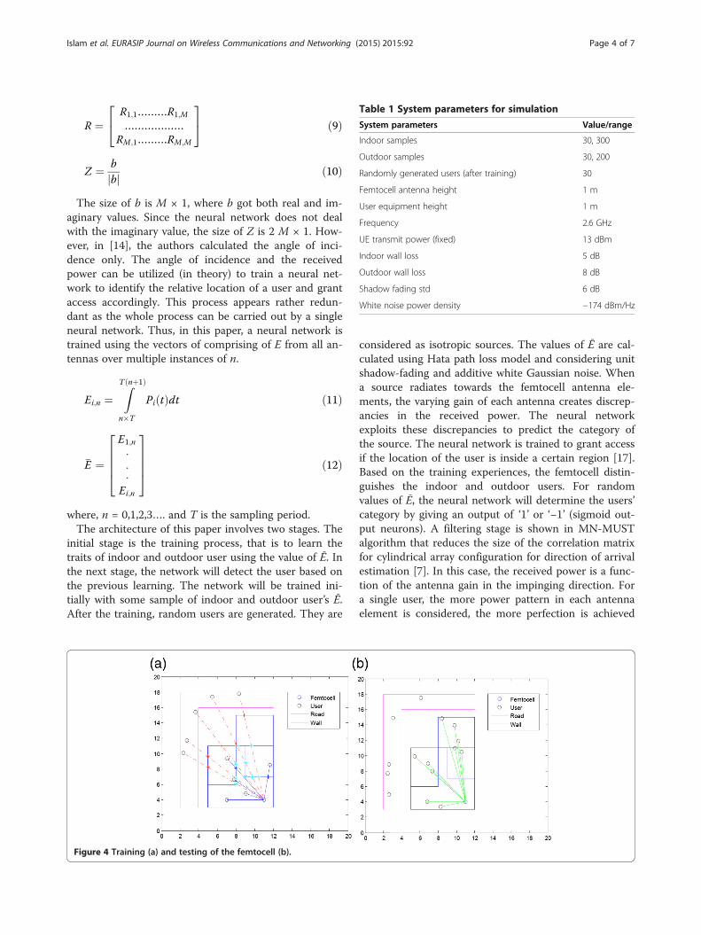
Table 1 System parameters for simulation
System parameters Value/range
Indoor samples 30, 300
Outdoor samples 30, 200
Randomly generated users (after training) 30
Femtocell antenna height 1 m
User equipment height 1 m
Frequency 2.6 GHz
UE transmit power (fixed) 13 dBm
Indoor wall loss 5 dB
Outdoor wall loss 8 dB
Shadow fading std 6 dB
White noise power density −174 dBm/Hz
Islam et al. EURASIP Journal on Wireless Communications and Networking (2015) 2015:92 Page 4 of 7
R ¼R1;1………R1;M
………………RM;1………RM;M
24
35 ð9Þ
Z ¼ bbj j ð10Þ
The size of b is M × 1, where b got both real and im-aginary values. Since the neural network does not dealwith the imaginary value, the size of Z is 2 M × 1. How-ever, in [14], the authors calculated the angle of inci-dence only. The angle of incidence and the receivedpower can be utilized (in theory) to train a neural net-work to identify the relative location of a user and grantaccess accordingly. This process appears rather redun-dant as the whole process can be carried out by a singleneural network. Thus, in this paper, a neural network istrained using the vectors of comprising of E from all an-tennas over multiple instances of n.
Ei;n ¼ZT nþ1ð Þ
n�T
Pi tð Þdt ð11Þ
�E ¼
E1;n
⋅⋅⋅
Ei;n
26664
37775 ð12Þ
where, n = 0,1,2,3…. and T is the sampling period.The architecture of this paper involves two stages. The
initial stage is the training process, that is to learn thetraits of indoor and outdoor user using the value of Ē. Inthe next stage, the network will detect the user based onthe previous learning. The network will be trained ini-tially with some sample of indoor and outdoor user’s Ē.After the training, random users are generated. They are
Figure 4 Training (a) and testing of the femtocell (b).
considered as isotropic sources. The values of Ē are cal-culated using Hata path loss model and considering unitshadow-fading and additive white Gaussian noise. Whena source radiates towards the femtocell antenna ele-ments, the varying gain of each antenna creates discrep-ancies in the received power. The neural networkexploits these discrepancies to predict the category ofthe source. The neural network is trained to grant accessif the location of the user is inside a certain region [17].Based on the training experiences, the femtocell distin-guishes the indoor and outdoor users. For randomvalues of Ē, the neural network will determine the users’category by giving an output of ‘1’ or ‘−1’ (sigmoid out-put neurons). A filtering stage is shown in MN-MUSTalgorithm that reduces the size of the correlation matrixfor cylindrical array configuration for direction of arrivalestimation [7]. In this case, the received power is a func-tion of the antenna gain in the impinging direction. Fora single user, the more power pattern in each antennaelement is considered, the more perfection is achieved

Figure 5 Performance analysis of the network.
Islam et al. EURASIP Journal on Wireless Communications and Networking (2015) 2015:92 Page 5 of 7
in the detection process with less number of trainingsamples.
4 Simulation and resultsTo analyze the performance of user classification tech-nique, a simulation environment is buildup in MATLAB™with a two-dimensional layout of a typical urban resi-dence. A femtocell is placed in a corner of the housewith a four-element (M = 4) antenna facing 90° apartfrom each other on the same plane. In Figure 4a,b, asample layout of the training and testing process is shown,respectively. The user equipment transmits omnidirec-tionally at 30 dB with no transmitting antenna gain. At thereceiving end, all four antennas have different antennagains for a particular user equipment. This reflects on thepower received by each antenna.
Figure 6 Best validation performance of ANN (a) and training state o
The simulations are event-based and according to3GPP standards. The plotted values are an average of1,000 independent simulations. For the duration of thesnapshot, all the users are assumed static so that the ef-fects due to Doppler spread are neglected. The systemparameters are given in Table 1. In Figure 5, the anten-nas are trained using 1 to 15 outdoor and 1 to 10 in-door users and in each step; the performance of thesystem is analyzed using 15 users randomly placedwithin the target area. All the users are assumed to bein the same elevation angle. The performance of thefemtocell is illustrated varying the amount of trainingdata. It clearly shows that the system benefits from theincreased amount of training data. Further, randomlyplaced 15 samples each for indoor and outdoor areas isenough to make the system practically error-free. Thefigure is generated after training the femtocell withnumber of users shown next to the axes below. The ini-tial stage with low outdoor users drags more errors inthe estimation of users than the indoor users. It is be-cause the outdoor users has more variation in their re-ceived signal power pattern than the indoors. However,after a certain number of training samples, the vari-ation decreases and ends up in the error-free regions.Again, for the indoor users, it requires less number ofuser samples.Figure 6a shows the mean square rate (MSE) of the of
the ANN training process with 15 indoor and 15 out-door users. Due to higher number of sample data points,the accuracy of the regular ANN training is more pre-cise. In Figure 6b, the validation check shows a good fit-ness. However, the training process is always dependenton the house geometry and the indoor situation of thehouse. Furniture, walls, and electronic equipment aremore of a concern in the indoor environment.
f ANN (b).

Figure 7 RSS level of the sample indoor users and outdoor users (a, b).
Islam et al. EURASIP Journal on Wireless Communications and Networking (2015) 2015:92 Page 6 of 7
A set of training sample is generated with one in-door and one outdoor users for each angle within thehouse and outside of the house. The angle is takenfrom 0° to 360° with a 2° angular separation. The twoindoor users are taken with a fair distance from eachother to consider the effect of indoor walls and indoorshadowing. The power level reading of one set of in-door and outdoor users is plotted for a four-elementantenna configuration. Figure 7a,b shows the powerlevel of indoor and outdoor users, respectively. Bothusers possess a multiple pattern of power reading foreach angle. The difference of level depends on the dir-ective pattern of the used sensing element, here, themicrostrip antenna. The line graphs of the indoor andthe outdoor curves have identical natures. The vari-ation of the angle for both users follows a particularpattern instead of having noise, wall loss, and shadow-ing effects.This study shows that the reconfigurable coverage
area may be achieved by using simple training datathat may be generated in real time if necessary. Thelarge single lobe radiation pattern of the antenna withprecisely desirable field of view allows the femtocell tooperate efficiently. This approach can be applied toany antenna fulfilling the above criteria. This flexibleapproach to femtocell design is not limited in the areaof coverage or total power of transmission. This con-cept is entirely scalable in terms of the area of cover-age. This adaptive technique also serves as an addedlayer of security over existing wireless systems. Further,it requires very little computation and memory. Thus,it is ideal for implementation in wireless routers, fem-tocells, or any form of selective wireless broadcastingsystem.
5 ConclusionsThe femtocell will occupy the major role in providinghigh indoor coverage in future cellular communicationnetwork. Closed access mechanism restricts the un-wanted users to connect to primary users’ personal fem-tocell. A cognitive closed access femtocell operation ispresented here using neural network for a multi-elementantenna femtocell. The performance of the system inrecognizing the environment improves in keeping withthe initial training values. The femtocell is trained by aset of trusted primary users. The training will remainvalid as long as the femtocell’s position and coveragearea are not altered. Thus, any such femtocell will coverany arbitrary region. In the future work, the process willbe developed for better femtocell performance with lesstraining illustration.
Competing interestsThe authors declare that they have no competing interests.
Authors’ contributionsNM and MJS have carried out the antenna specification part, while MTI andMI constructed the main concept of the article. TBAR and AUA havedeveloped the coding, accumulated others work, and wrote down themanuscript. All authors read and approved the final manuscript.
AcknowledgementsThe research was supported by Ministry of Education (MOE), Malaysia, underthe grant scheme no. FRGSTOPDOWN/2014/TK03/UKM/01/1 and ICT fellowshipgrant for higher education and research in Information and CommunicationTechnology under the Ministry of Post, Telecommunication and InformationTechnology, Bangladesh.
Received: 19 May 2014 Accepted: 2 March 2015
References1. G De La Roche, A Valcarce, D López-Pérez, J Zhang, Access control
mechanisms for femtocells. IEEE Commun. Mag. 48, 33–39 (2010)

Islam et al. EURASIP Journal on Wireless Communications and Networking (2015) 2015:92 Page 7 of 7
2. AU Ahmed, MT Islam, M Ismail, A Review on femtocell and its diverseinterference mitigation techniques in heterogeneous network. Wireless Pers.Commun. 78, 85–105 (2014)
3. X Chu, Y Wu, L Benmesbah, W-K Ling, Resource allocation in hybrid macro/femto networks, in 2010 IEEE Wireless Communications and NetworkingConference Workshops (WCNCW), 2010, p. 1–5
4. AU Ahmed, MT Islam, M Ismail, M Ghanbarisabagh, Dynamic resourceallocation in hybrid access femtocell network. Sci. World J. 2014, 7 (2014)
5. H Claussen, F Pivit, Femtocell coverage optimization using switchedmulti-element antennas, in IEEE International Conference on Communications,ICC’09, 2009, p. 1–6
6. H Claussen, F Pivit, LT Ho, Self‐optimization of femtocell coverage tominimize the increase in core network mobility signalling. Bell Labs Tech.J. 14, 155–183 (2009)
7. ZD Zaharis, C Skeberis, TD Xenos, PI Lazaridis, J Cosmas, Design of a novelantenna array beamformer using neural networks trained by modifiedadaptive dispersion invasive weed optimization based data. IEEE Trans.Broadcast. 59, 455–460 (2013)
8. TG Basha, P Sridevi, MG Prasad, Beam forming in smart antenna withprecise direction of arrival estimation using improved MUSIC. Wireless Pers.Commun. 71(2), 1353–1356 (2012)
9. M Agatonović, Z Stanković, N Dončov, L Sit, B Milovanović, T Zwick,Application of artificial neural networks for efficient high-resolution 2D DOAestimation. Radioengineering 21, 1179 (2012)
10. D Inserra, AM Tonello, A multiple antenna wireless testbed for thevalidation of DoA estimation algorithms. AEU Int. J. Electron. Commun.68, 10–18 (2014)
11. N Fonseca, M Coudyser, J-J Laurin, J-J Brault, On the design of a compactneural network-based DOA estimation system. IEEE Trans. Antennas Propag.58, 357–366 (2010)
12. J Dudczyk, A Kawalec, Adaptive forming of the beam pattern of microstripantenna with the use of an artificial neural network. Int. J. Antennas Propag.2012, Article ID 935073, 13 pages (2012). doi:10.1155/2012/935073
13. T Ghouse Basha, A George, B Rajakumar, G Prasad, P Sridevi, A constructivesmart antenna beam-forming technique with spatial diversity. IET Microw.Antennas Propag. 6, 773–780 (2012)
14. TG Basha, MG Prasad, P Sridevi, Hybrid technique for beam formingin smart antenna with spatial diversity. Int. J. Wirel. Mob. Comput.5, 126–136 (2012)
15. AU Ahmed, MT Islam, R Azim, M Ismail, MF Mansor, Microstrip antennadesign for femtocell coverage optimization. Int. J. Antennas Propag.2014, 8 (2014)
16. AH El Zooghby, CG Christodoulou, M Georgiopoulos, A neural network-basedsmart antenna for multiple source tracking. IEEE Trans. Antennas Propag.48, 768–776 (2000)
17. S Caylar, G Dural, K Leblebicioglu, Neural network method for direction ofarrival estimation with uniform cylindrical microstrip patch array. IET Microw.Antennas Propag. 4, 153–161 (2010)
Submit your manuscript to a journal and benefi t from:
7 Convenient online submission
7 Rigorous peer review
7 Immediate publication on acceptance
7 Open access: articles freely available online
7 High visibility within the fi eld
7 Retaining the copyright to your article
Submit your next manuscript at 7 springeropen.com