coding and error control. class contents error control error detection parity check cyclic...
TRANSCRIPT
Coding and Error Control

Class Contents Error Control Error Detection
Parity Check Cyclic Redundancy Check
Modulo 2 Arithmetic Polynomials Digital Logic
Block Error Correction Codes Block Code Principles Hamming Code Cyclic Codes
BCH Codes Reed-Solomon Codes
Automatic Repeat Request Flow Control Error Control using Go-Back-N ARQ.
Error Control
Error Detection Codes
Error Correction Codes (FEC)
Automatic Repeat Request (ARQ)
Approaches to treat errors in data transmissions

Error Detection
Data Transmission occurs in Frames
Probability of Error per frame definitions
Pb: Probability of a single bit error – Bit Error Rate (BER)
P1: Probability that a frame arrives with no bit errors
P2: Probability that, with and error detection algorithm in use, a frame arrives with 1 or more undetected errors.
P3: Probability that, with and error detection algorithm in use, a frame arrives with 1 or more detected bit errors but no undetected bit errors.
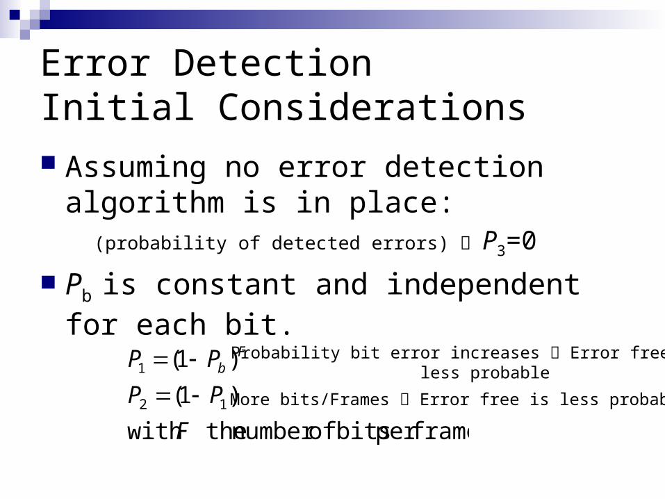
Error Detection Initial Considerations Assuming no error detection algorithm is in
place:(probability of detected errors) P3=0
Pb is constant and independent for each bit.
frameper bits ofnumber thewith
)1(
)1(
12
1
F
PP
PP Fb
More bits/Frames Error free is less probable
Probability bit error increases Error free is less probable
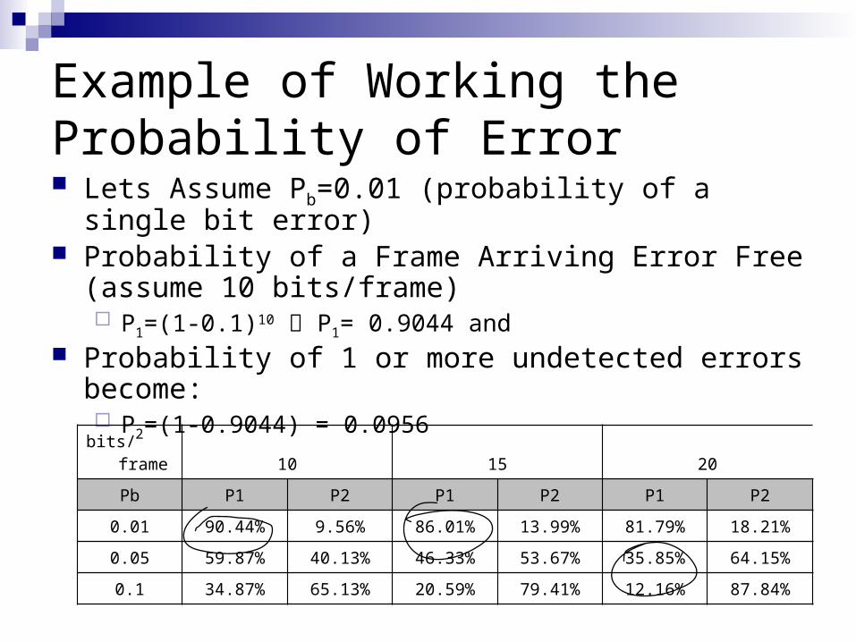
Example of Working the Probability of Error Lets Assume Pb=0.01 (probability of a single bit error) Probability of a Frame Arriving Error Free (assume 10
bits/frame) P1=(1-0.1)10 P1= 0.9044 and
Probability of 1 or more undetected errors become: P2=(1-0.9044) = 0.0956
bits/frame 10 15 20
Pb P1 P2 P1 P2 P1 P2
0.01 90.44% 9.56% 86.01% 13.99% 81.79% 18.21%
0.05 59.87% 40.13% 46.33% 53.67% 35.85% 64.15%
0.1 34.87% 65.13% 20.59% 79.41% 12.16% 87.84%
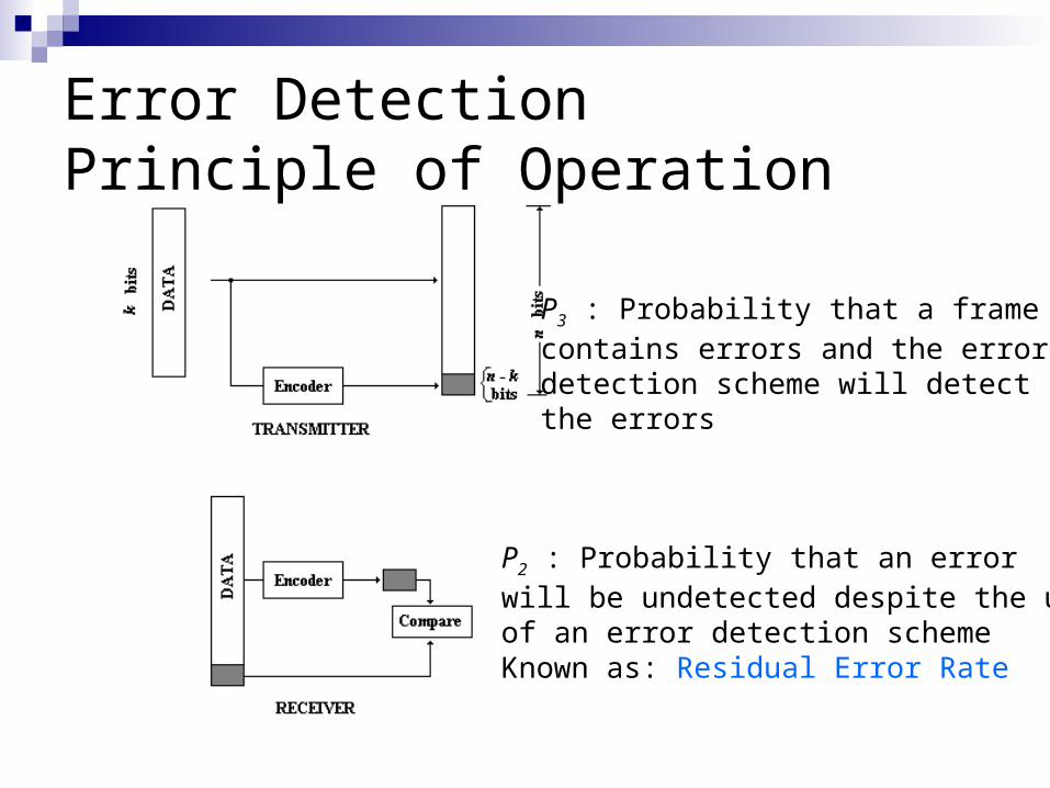
Error Detection Principle of Operation
P2 : Probability that an errorwill be undetected despite the useof an error detection scheme Known as: Residual Error Rate
P3 : Probability that a framecontains errors and the errordetection scheme will detectthe errors

Error Detection Techniques:Parity Check Parity Bit
Odd Parity
Even Parity
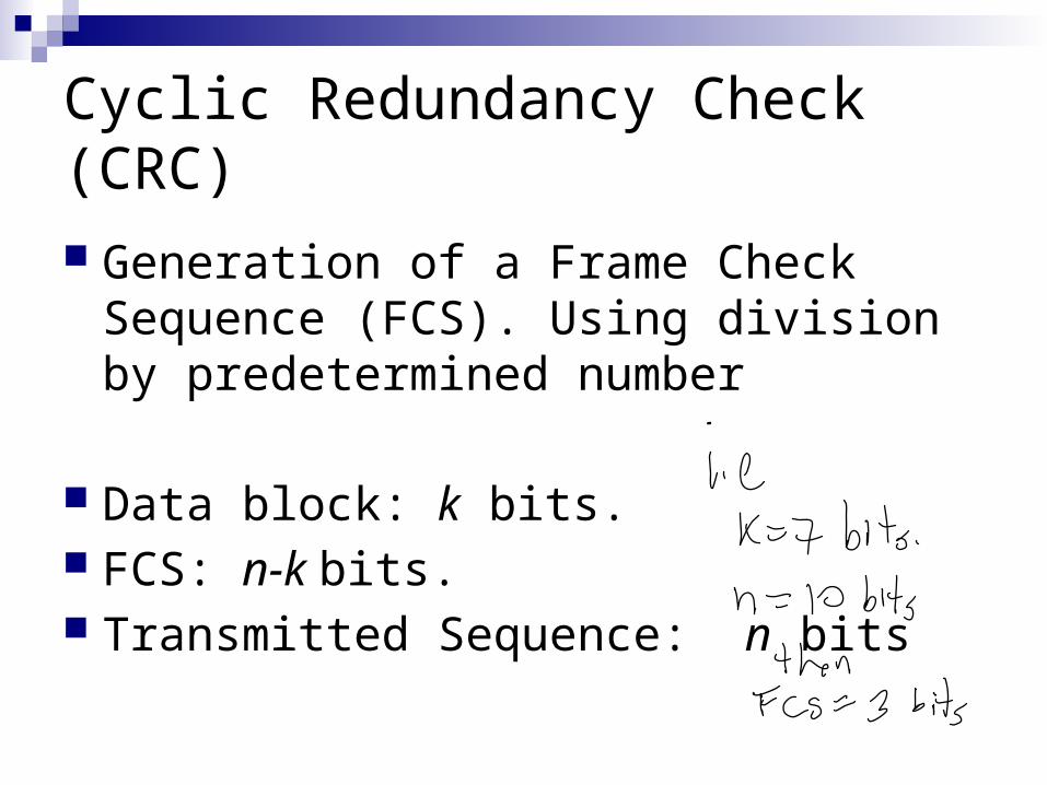
Cyclic Redundancy Check (CRC)
Generation of a Frame Check Sequence (FCS). Using division by predetermined number
Data block: k bits. FCS: n-k bits. Transmitted Sequence: n bits
Cyclic Redundancy CheckProcedure Description Ways
Modulo 2 Arithmetic
Polynomials
Digital Logic

CRC – Modulo 2 Arithmetic
Use of binary addition with no carry:
1111+1010 0101
1111- 0101 1010
11001 x11 1100111001 101011
0AA
A1A
A0A

CRC – Modulo 2 Arithmetic Definitions:
T = n-bit frame to be transmitted
D = k-bit block of data. (The first k bits of T)
F = (n-k)-bit FCS. (The last n-k bits of T)
P = pattern of n-k+1 bits; (predetermined divisor)

CRC – Modulo 2 Arithmetic
FDT kn 2 Construction of T
Bit shift n-k positions to left
To Find F, we need to divide the shifted data by the predetermined divisor P
P
RQ
P
Dkn
2 The remaining will be the FCS
The transmitted signalwill be exactly divisible by P

Modulo 2 Numerical Example
Given the following:Message D = 1010001101Divisor Pattern P = 110101FCS R = ?
Length of Frame Check sequence is 1 bit less than the pattern
k = 10 n-k =5 n = 15
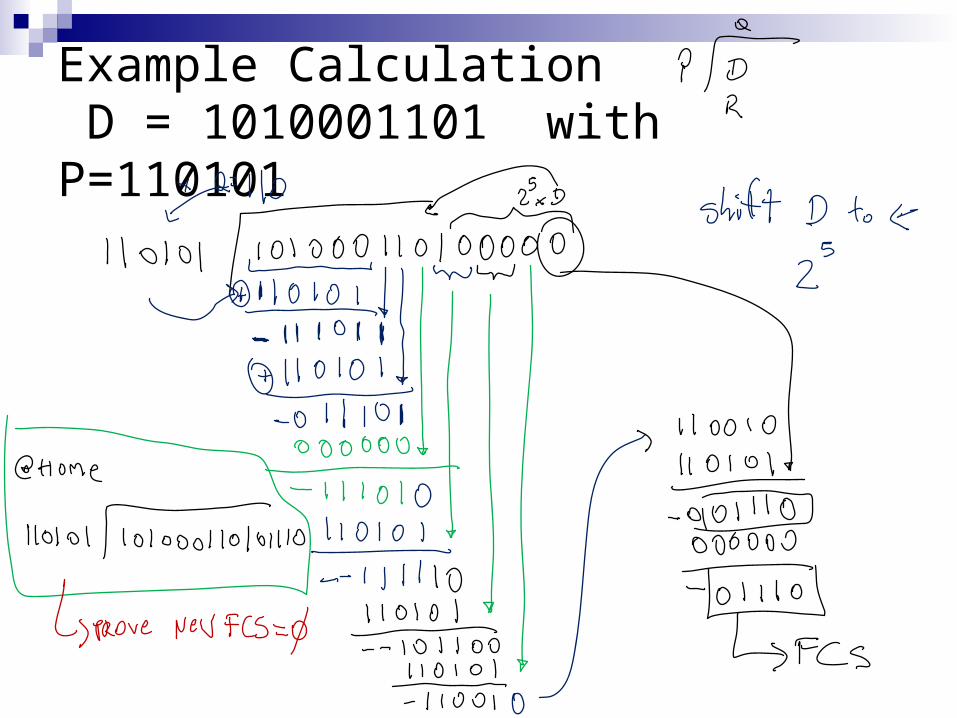
Example Calculation D = 1010001101 with P=110101

Modulo 2 Arithmetic – Notes
P is chosen to be 1 bit longer than the FCS.
At minimum, both the high and low-order bits of P must be 1.
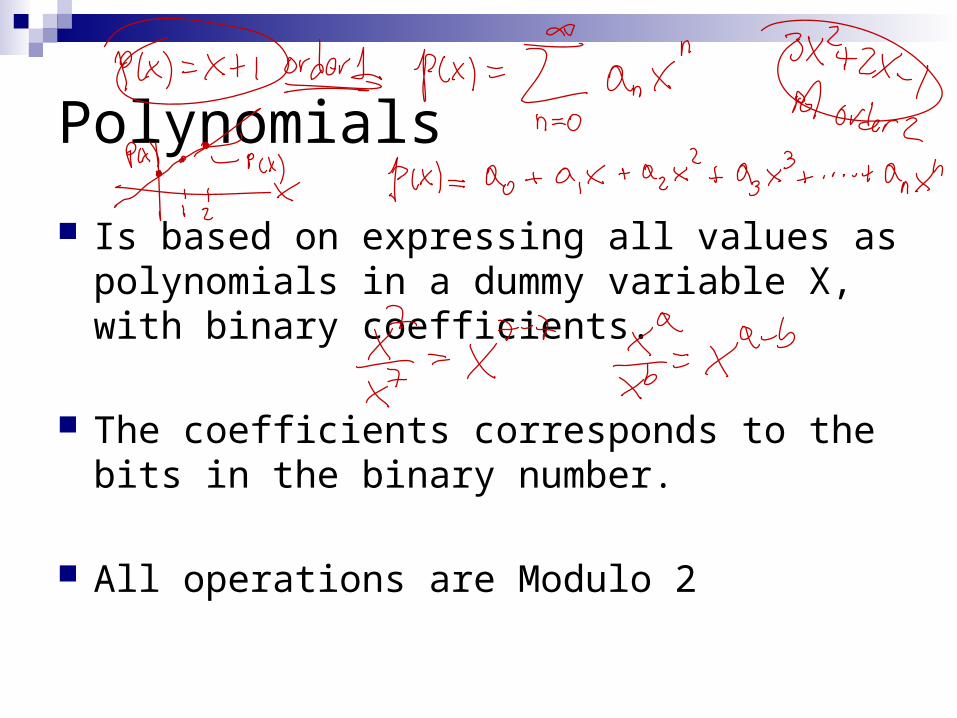
Polynomials
Is based on expressing all values as polynomials in a dummy variable X, with binary coefficients.
The coefficients corresponds to the bits in the binary number.
All operations are Modulo 2

Polynomials
Transmitted Frame:
)()()( XRxDXXT kn
Polynomial Shift (grade increased)
FCS: remainder of divisionby polynomial P(X)
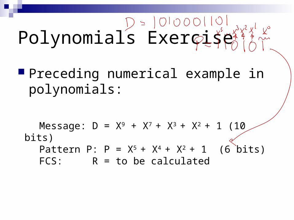
Polynomials Exercise
Preceding numerical example in polynomials:
Message: D = X9 + X7 + X3 + X2 + 1 (10 bits)
Pattern P: P = X5 + X4 + X2 + 1 (6 bits)FCS: R = to be calculated

Polynomial Detectable Errors
All Single bit errors (P(X) has more than 1 nonzero term)
All double bit errors (P(X) has a factor with 3 terms)
Any odd number of errors (P(X) contains a factor (X+1))
Any Burst Error with length less than or equal to the length of the FCS.
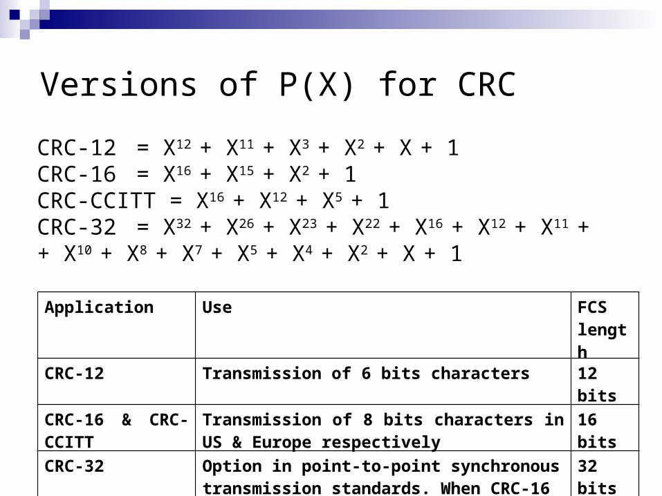
Versions of P(X) for CRC
CRC-12 = X12 + X11 + X3 + X2 + X + 1 CRC-16 = X16 + X15 + X2 + 1CRC-CCITT = X16 + X12 + X5 + 1CRC-32 = X32 + X26 + X23 + X22 + X16 + X12 + X11 + + X10 + X8 + X7 + X5 + X4 + X2 + X + 1
Application Use FCS length
CRC-12 Transmission of 6 bits characters 12 bits
CRC-16 & CRC-CCITT
Transmission of 8 bits characters in US & Europe respectively
16 bits
CRC-32 Option in point-to-point synchronous transmission standards. When CRC-16 is not adequate.
32 bits
Digital Logic CRC process represented and implemented by
a dividing circuit consisting of XOR gates and a shift-register.

Block Error Detection Codes Forward Error Correction(FEC) Wireless Comms. have a high BER
Block Error Detection Codes enables the receiver to correct errors in an incoming transmission in the basis of the bits in the transmission

Block Error Detection Codes – Forward Error Correction

FEC decoder output No Errors: input of FEC decoder is identical to
original codeword, and the codeword produces the original data block as output.
Error Detected and Corrected: occur for certain patterns. FEC can map erroneous block into original data
Error Detected but Not Corrected: Report is uncorrectable error found.
Error Not Detected: Occurs for rare error patterns. The received block is mapped incorrectly.
Block Code Principles
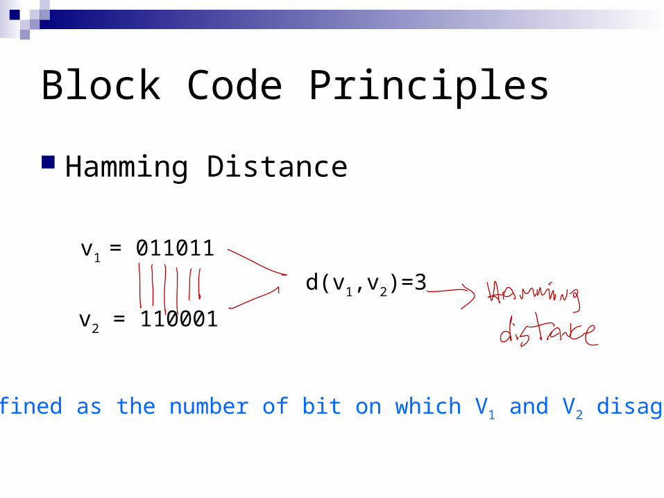
Hamming Distance
v1 = 011011
v2 = 110001
d(v1,v2)=3
Defined as the number of bit on which V1 and V2 disagree
Block Code Principle - Example
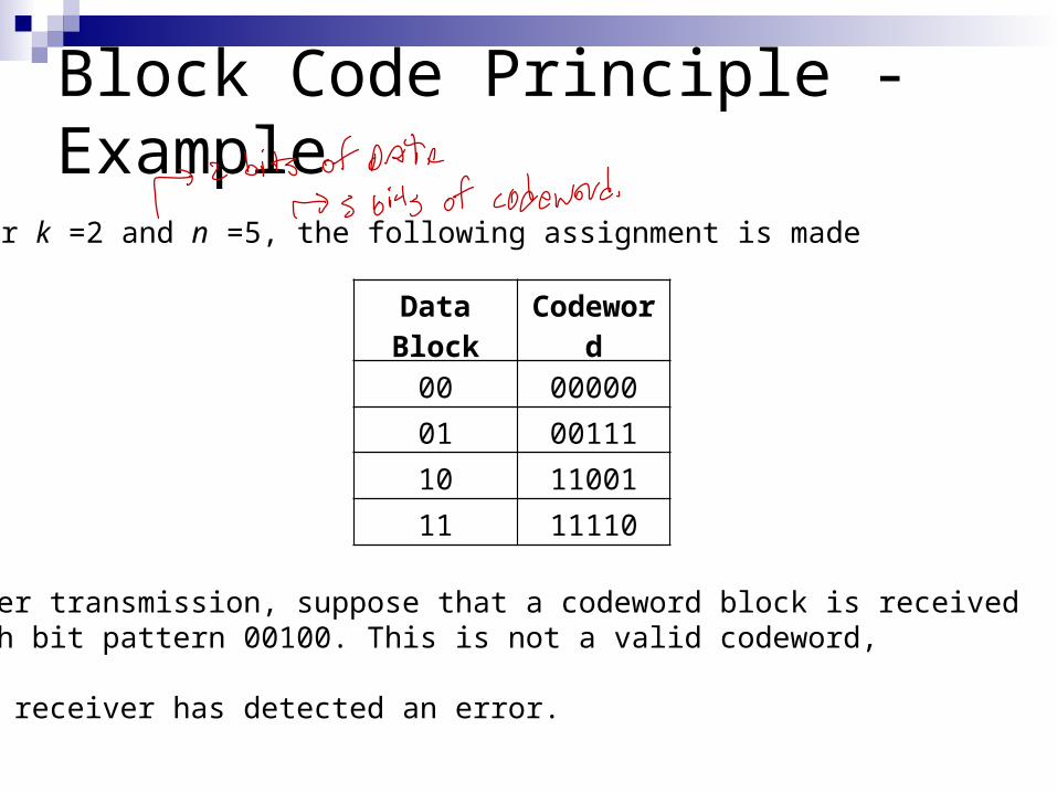
For k =2 and n =5, the following assignment is made
Data Block Codeword
00 00000
01 00111
10 11001
11 11110
After transmission, suppose that a codeword block is received with bit pattern 00100. This is not a valid codeword,
The receiver has detected an error.
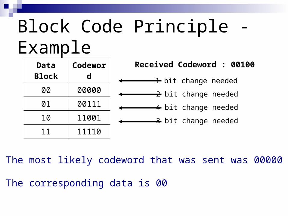
Block Code Principle - ExampleData Block Codeword
00 00000
01 00111
10 11001
11 11110
Received Codeword : 00100
2 bit change needed
4 bit change needed
3 bit change needed
1 bit change needed
The most likely codeword that was sent was 00000
The corresponding data is 00

Rule: If an invalid codeword is received, the valid codeword that is closest to it is selected.
This only works if there is only 1 valid codeword at minimum distance from each codeword.
In an (n,k) block code, there are 2k valid codewords out of a total of 2n
Block Code Principle - Example

InvalidCodeword
Minimumdistance
Valid Codeword
InvalidCodeword
Minimumdistance
Valid Codeword
00001 1 00000 10000 1 00000
00010 1 00000 10001 1 11001
00011 1 00111 10010 2 00000 or 11110
00100 1 00000 10011 2 00111 or 11001
00101 1 00111 10100 2 00000 or 11110
00110 1 00111 10101 2 00111 or 11001
01000 1 00000 10110 1 11110
01001 1 11001 10111 1 00111
01010 2 00000 or 11110 11000 1 11001
01011 2 00111 or 11001 11010 1 11110
01100 2 00000 or 11110 11011 1 11001
01101 2 00111 or 11001 11100 1 11110
01110 1 11110 11101 1 11001
01111 1 00111 11111 1 11110
Block Code Principle - Example
Error Detected but Not Corrected
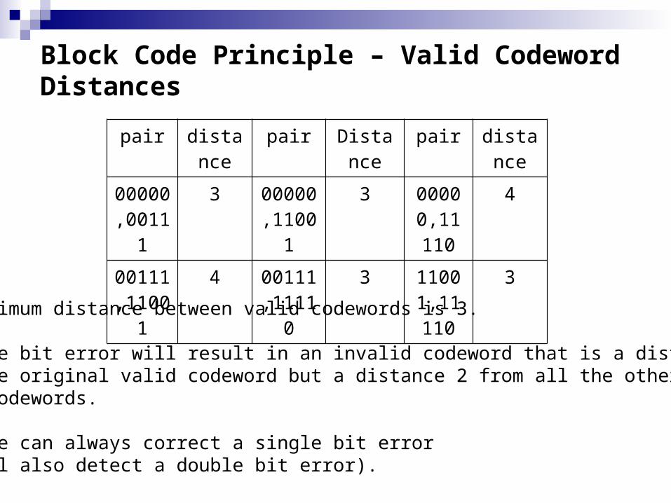
Block Code Principle – Valid Codeword Distances
pair distance
pair Distance
pair distance
00000,00111
3 00000,11001
3 00000,11110
4
00111,11001
4 00111,11110
3 11001,11110
3
The minimum distance between valid codewords is 3.
A single bit error will result in an invalid codeword that is a distance 1 from the original valid codeword but a distance 2 from all the other valid codewords.
The code can always correct a single bit error (It will also detect a double bit error).

Block Code - Summary
An (n,k) block code encodes k data bits on n block bits (n>k)
Each valid codeword, reproduces the original k data bits and adds to them n-k check bits to form the n-bit codeword.
Redundancy of the code is the ratio redundant bits to data bits: (n-k)/k
Code Rate is the ratio of data bits to total bits. It is a measure of how much additional bandwidth is required to carry data at the same rate as without the code.
k/n

Considerations in Block Code Design. For any given n and k, we would like the largest
possible value of dmin.
The code should be relatively easy to encode and decode, requiring minimal memory and processing time
The number of extra bits should be small to reduce bandwidth
The number of extra bits should be high to reduce error rate.

Hamming CodeBlock Length:Number of Data Bits:Number of Check Bits:Minimum Distance:
12 mn
12 mk m
mkn 3min d
where 3m
• Hamming codes are designed to correct single bit errors.
• The encoding process preserves the k data bits and adds n-k check bits.
• For decoding, the comparison logic receives as input two (n-k)-bit values, one from the incoming codeword, and one from the calculation performed on the incoming data bits.
• A bit-by-bit comparison is done (using XOR) and the result is called the syndrome word. Each bit of the syndrome is 0 or 1 according to whetherthere is or is not a match in that bit position for the two inputs.
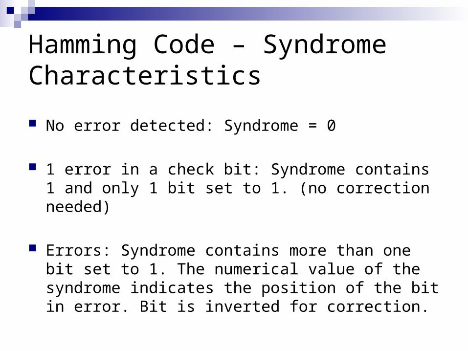
Hamming Code – Syndrome Characteristics
No error detected: Syndrome = 0
1 error in a check bit: Syndrome contains 1 and only 1 bit set to 1. (no correction needed)
Errors: Syndrome contains more than one bit set to 1. The numerical value of the syndrome indicates the position of the bit in error. Bit is inverted for correction.
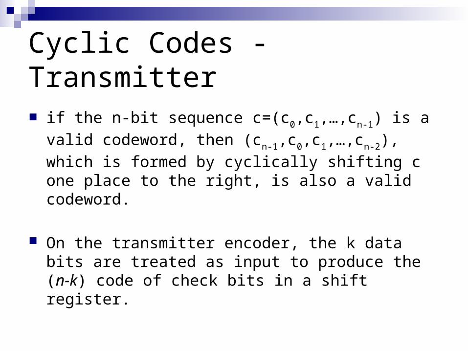
Cyclic Codes - Transmitter
if the n-bit sequence c=(c0,c1,…,cn-1) is a valid codeword,
then (cn-1,c0,c1,…,cn-2), which is formed by cyclically
shifting c one place to the right, is also a valid codeword.
On the transmitter encoder, the k data bits are treated as input to produce the (n-k) code of check bits in a shift register.
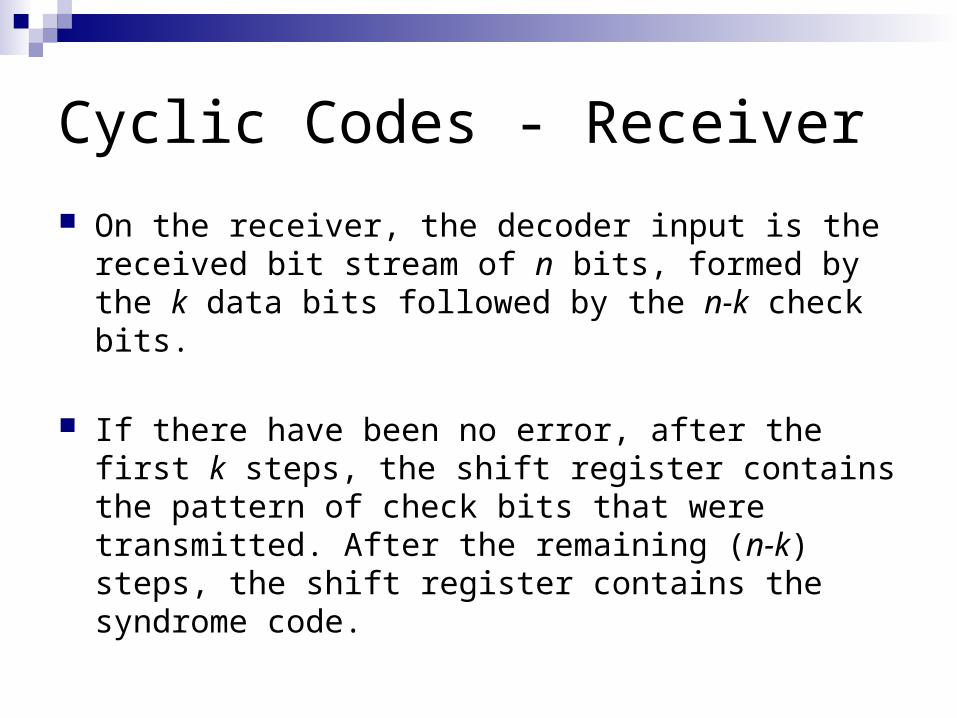
Cyclic Codes - Receiver
On the receiver, the decoder input is the received bit stream of n bits, formed by the k data bits followed by the n-k check bits.
If there have been no error, after the first k steps, the shift register contains the pattern of check bits that were transmitted. After the remaining (n-k) steps, the shift register contains the syndrome code.
Cyclic Codes - Decoding
Process the bits to compute the syndrome code in exactly the same way as the encoder processes the data bits to produce the check code.
If the syndrome bits are all zero, no error has been detected.
If the syndrome is non-zero, perform additional processing on the syndrome for error correction.
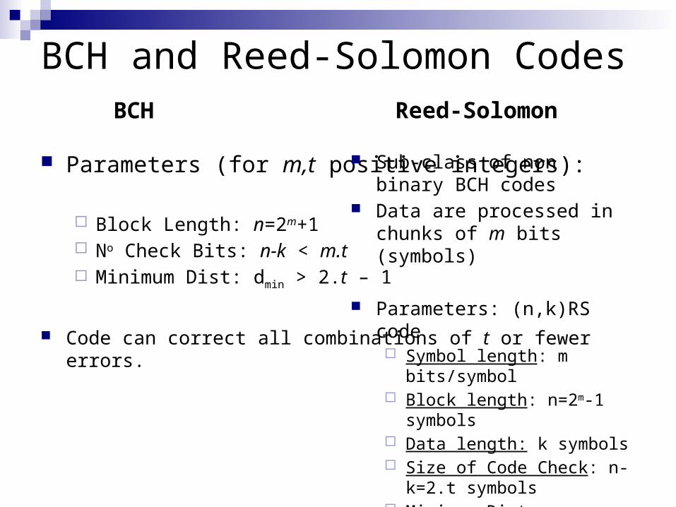
BCH and Reed-Solomon Codes
Parameters (for m,t positive integers):
Block Length: n=2m+1 No Check Bits: n-k < m.t Minimum Dist: dmin > 2.t – 1
Code can correct all combinations of t or fewer errors.
Sub-class of non binary BCH codes
Data are processed in chunks of m bits (symbols)
Parameters: (n,k)RS code Symbol length: m bits/symbol Block length: n=2m-1 symbols Data length: k symbols Size of Code Check: n-k=2.t
symbols Minimum Distance: dmin=2.t+1
symbols
BCH Reed-Solomon

Automatic Repeat Request (ARQ) Is a Mechanism used in data link control and
transport protocols; it relies in the use of an error detection code (such as CRC)
ARQ error control mechanism is part of a flow control mechanism that is part of these protocols.
Definition: PDU (protocol data unit): Is a set of data specified in a protocol consisting of protocol control information and data.

Flow Control
Technique used to ensure that a receiver is not overwhelmed by the transmitter with data.
Based on the allocation of a data buffer in the receiver (with some maximum length). Both Tx and Rx know the size of the buffer and transmit accordingly

Flow Control
Characteristics of Transmission:Data is sent in a sequence of PDUsPDUs arrive in the same order in which they
are sent.Each PDU suffers an arbitrary and variable
amount of delay before reception.

Flow Control

Error Control
Mechanism used to detect and correct errors in PDU transmission.
In addition to the flow control transmission characteristics, we allow for 2 types of errors: Lost PDU: PDU fails to arrive at the receiver. Damaged PDU: A recognizable PDU does arrive, but
some of the bits are in error.
Error Control Techniques - ARQ
Error Detection: The receiver detects errors and discards PDU that are in error
Positive Acknowledgement: The destination returns a positive acknowledgment to successfully received, error-free PDUs.
Error Control Techniques - ARQ
Retransmission after time-out: The source retransmits a PDU that has not been acknowledged after a predetermined amount of time.
Negative acknowledgment and retransmission: The destination returns a negative acknowledgement to PDUs in which an error is detected. The source retransmits such PDUs.

ARQ
Collectively, these mechanism are all referred to as automatic repeat request (ARQ)
The effect of ARQ is to turn an unreliable data link into a reliable one.
The most commonly used version of ARQ is known as go-back-N ARQ which is based on a “sliding-window” flow control mechanism.

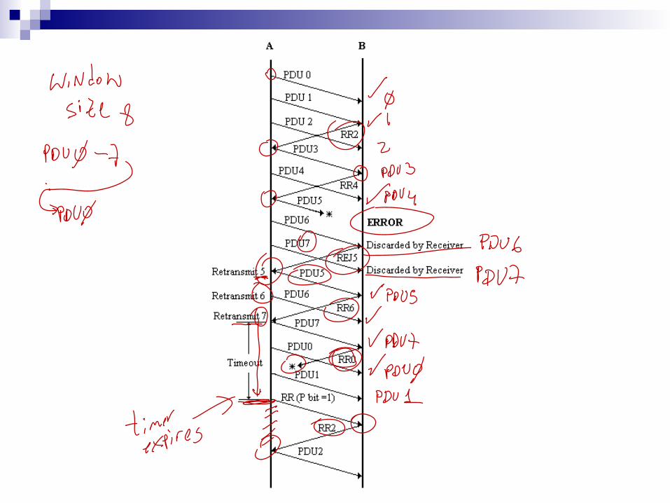
Go-back-N ARQ
In this technique, a station may send a series of PDUs sequentially numbered modulo some maximum value.
The number of unacknowledged PDUs outstanding is determined by the size of the window.

Go-back-N ARQTypes of Acknowledgements
Receive Ready (RRx): PDU(x-1) received.
Reject (REJx): PDUx received erroneously. Discarded and wait until retransmission is done.
Transmitter RR comand (Pbit): Used when transmission timer for acknowledge runs out. Receiver MUST acknowledge with RRx

Go-back-N ARQContingencies: Tx: A, Rx: B
1. Damaged PDU. If the received PDU is invalid (B detects an error), B discards the PDU and takes no further action as the result of that PDU. There are two subcases:
a) Within reasonable period of time, A subsequently sends PDU(i+1). B receives PDU(i+1) out of order and sends a REJi. A must retransmit PDUi and subsequent PDUs.
b) A does not soon send additional PDUs. B receives nothing and returns neither RR nor a REJ. When A’s timer expires, it transmits a RR PDU that includes a bit known as the P bit, which is set to 1. B interprets the RR PDU with a P bit of 1 as a command that must be acknowledged by sending an RR indicating the next PDU that it expects, which is PDUi. When A receives the RRi, it retransmits PDUi.
Go-back-N ARQContingencies:Tx: A, Rx: B
2. Damaged RR. There are two subcases:a) B receives PDUi and sends RR(i+1), which suffers an error in
transit. Because acknowledgement are cumulative (RR6 means all PDU through 5 are acknowledged), it may be that A will receive a subsequent RR to a subsequent PDU and that it will arrive before the timer associated with PDUi expires.
b) If A’s timer expires, it transmits an RR command as in case 1b. It sets another timer, called the P-bit timer. If B fails to respond to the RR command, or if its response suffers an error in transit, then A’s P-bit timer will expire. At this point, A will try again by issuing a new RR command and restarting the P-bit timer.
3. Damaged REJ. If a REJ is lost, this is equivalent to case 1b.