code of practice piggeries 1992 - planning - planning · (ii) 4.62 reduction formula 12 4.63...
TRANSCRIPT


CODE OF PRACTICE
PIGGERIES
First Published 1984ByHealth Commission of Victoria andDepartment of Agriculture, Victoria
In consultation withMinistry for Planning and Environment, VictoriaEnvironment Protection AuthorityVictorian Farmers' and Graziers' Association (Pig Branch)Australian Institute of Health Surveyors (Victorian Division)Victorian Pork and Bacon CouncilSoil Conservation Authority
Principal Author: R.E. Eden, B.Sc., AMICE, MIHE, Health Commission of Victoria.
REVISED 1992,By the Technical Advisory Committee involving
Department of Food and AgricultureDepartment of Planning and HousingEnvironment Protection AuthorityHealth Department, VictoriaVictorian Farmers Federation (Pig Commodity Group)Australian Institute of Environmental Health (Victorian Division)
(The Technical Advisory Committee was appointed to provide for an ongoing review of the Code ofPractice - Piggeries. The Committee reports through the Minister of Agriculture to the Minister of Planningand Housing).
Code of Practice - Piggeries.
Rev. 1992ISBN 0 7306 1572 3.
1. Swine - Housing - Victoria - Standards. I. Victoria. Dept. of Agriculture.
636.4083109945
(i)
CONTENTS
1.0 General requirements for establishing a piggery 1
1.1 Introduction 11.2 Topography 2
1.3 Soils 21.4 Land liable to flooding 21.5 Future extensions to a piggery 21.6 Fencing 31.7 Stock records 31.8 Stock in excess of the permitted maximum 31.9 Water Supplies 31.10 Reuse of waste waters 3
2.0 Piggery classifications 4
2.1 Piggery classifications 42.2 Breeder-only classification 4
3.0 Definitions used in buffer zone terminology 5
4.0 Buffer zone dimensions (distances) for a piggery 8
4.1 Fixed and variable buffer zones 84.2 Reduction in variable buffer zone dimensions (distances) 84.3 Fixed buffer zones (dimensions) for a piggery 84.4 Calculation of distances for the variable buffer zones of a standard piggery 10
4.41 Introduction 104.42 Piggeries having R-values in the range 4 to 500 104.43 Piggeries having R-values in the range 501 to 2000 104.44 Piggeries having R-values in excess of 5000 104.45 Table of R-values and zone distances 11
4.5 Variable buffer zone dimensions for specific conditions 114.6 Reduction in variable buffer zone dimensions (distances) for a piggery 11
4.61 Reduction factors- Emissions to air from buildings 13- Effluent collection system within all pig buildings 13- Effluent collection system outside all pig buildings (but within the piggery compound) 13- Effluent treatment system (within the piggery compound) 13- Noise 13- Power supplies for ventilation, effluent handling and pumping 13- Management 13
(ii)
4.62 Reduction formula 124.63 Examples - Piggery with a radial buffer 144.64 - Dispersed or extensive piggery 15
4.7 Buffer distances surrounding effluent treatment systems or land disposal areas 16
4.71 Effluent treatment systems (categories) 164.72 Effluent disposal to land (categories) 174.73 Table of buffer distances surrounding effluent treatment systems or
land disposal areas 18
5.0 Design requirements for buildings 19
5.1 General 195.2 Intensive and semi-intensive piggery units 195.3 Extensive and semi-extensive piggery units 195.4 Drainage surrounding a piggery 195.5 Environmental control and working conditions in enclosed spaces 20
6.0 Operating requirements 21
6.1 Noise6.11 Hearing conservation 216.12 Other limits 21
6.2 General Safety6.21 Entry into confined spaces 22
6.3 Flies and fly-breeding 226.4 Storage and disposal of containers and toxic substances 226.5 Feed and feed storage 226.6 Disposal of dead pigs and other biological material 236.7 Installation of equipment 236.8 Operation and maintenance of equipment 236.9 Incineration 236.10 Lagoons 24
7.0 Disposal of effluent 25
7.1 Disposal to land 257.2 Soil-testing (Introduction) 257.3 Soil-testing for hydraulic loading 257.4 Disposal to boulder-strewn land 267.5 Disposal of effluent via a borehole 267.6 Combination of effluent with other waters 26
7.61 Sullage 267.62 Sewage 277.63 Water derived from irrigation channels or
watercourses (including boreholes) 27

(iii)
APPENDICES
1. Double ring infiltrometer test 28
2. Percolation test 29
3. Determination of buffer zone dimensions when prevailing wind conditions apply 31
Piggeries classified as having a piggery reference point 31Example - Buffer zone distances when prevailing wind conditions apply 32
Piggeries classified as dispersed or extensive 33Example - Buffer zones for a dispersed piggery in prevailing wind conditions 33
4. Determination of buffer zone dimensions when constrained wind conditions apply 34
Example - Buffer zone dimensions when constrained wind conditions apply 34
5. Determination of buffer zone dimensions when significant topography conditionsapply 35
Case 1 - Piggery surrounded by significant topography on two or more sides 35Case 2 - Piggery having significant topography on one side only 35
Example - Buffer zones for piggeries surrounded by significanttopography on two or more sides 37
- Piggery (having a piggery reference point) in the vicinityof an isolated hill 38
- Dispersed piggery in the vicinity of an isolated hill 38

1
Note 1 - This applies to existing piggeries where planning approvals to the responsible authority for substantial modifications(allowing for an additional 10% or greater increase in pigs) occur on or after February 26, 1988.Refer to Land Protection Act 1970, State Environmental Protection Policy, Waters of Victoria.
Note 2 - A companion volume titled Guidelines for the Siting and Operation of Piggeries will provide additional material to assistboth new and existing piggeries.
Note 3 - While it has been common practice to refer to the size of a piggery in terms of "sow-units", currently many piggeriesoperate as "breeder-only" or "grower-only" units, which makes the "sow-unit" a meaningless term.A modified R-value applies specifically to "breeder-only" piggeries - see Section 2.2.
1.0 GENERAL REQUIREMENTS FOR ESTABLISHING A PIGGERY
1.1 INTRODUCTION
The Code of Practice - Piggeries specifies minimal standards that apply to new piggeries orwhere there are substantial modifications to existing piggeries (see Note 1 and Note 2).
This Code of Practice - Piggeries and the companion volume entitled Guidelines for the Sitingand Operation of Piggeries (see Note 2) are designed to assist municipal councils, pig producersand planning authorities in the proper establishment and operation of new piggeries or wherethere are major modifications to existing piggeries.
It is in the interest of the producer, the pig industry and the general community that piggeries areestablished and managed efficiently, with minimal environmental impact and disturbance to thelocal area.
Potential producers and other persons having an interest in the establishment and control ofpiggeries are advised to contact the responsible municipal authority at an early stage to ascertainany local by-laws/regulations relating to piggeries.
Constant developments in husbandry techniques, animal welfare and utilisation of effluent willensure continuing improvements in environmental standards. Every encouragement is thereforegiven to innovators who, on sound practical or technical advice, introduce new or improvedtechniques.
Effluents from agricultural operations are valuable resources, which only become "wastes" ifthe operator or community fails to utilise such assets. In the future these resources may becomeas much a part of the overall economic system as the actual production of animal protein forhuman consumption.
Throughout this Code of Practice the total number of pigs registered is known as the "R-value". For this purpose any living pig from birth onwards is defined as a pig (see Note 3).
The Code of Practice does NOT cover detailed aspects of animal husbandry and design andoperational requirements of piggeries. Responsible authorities and potential pig producersshould refer to the Guidelines document and other publications on pig production.

2
Note 1 - The Rural Water is a reliable source of flood frequency information.
Note 2 - The total of a 100% increase in pig numbers will normally be calculated with reference to the pig numbers previouslypermitted by the responsible authority.
1.2 TOPOGRAPHY
The site should be on undulating or flat terrain to minimise soil erosion. When the proposeddisposal area, or part thereof, contains land which has a slope of 10% or greater, a check shallbe made to determine whether there is sufficient land of a lesser grade which is capable ofabsorbing all the effluent which will be produced from the piggery on a year round basis. Where there is insufficient land available provision shall be made for an alternative system (e.g.a lagoon) which will have sufficient capacity to retain or treat the excess effluent. This will notpreclude the use of other more steeply graded land when conditions are favourable but if land ofslopes greater than 10% is used for disposal then provision shall be made to minimise erosion.
1.3 SOILS
(Although not a specific item of this Code of Practice, soils should ideally be a medium loam-clay to provide reasonably good drainage and retention of nutrients (e.g. nitrogen andphosphorus). Sandy soils offer good surface drainage but effluent disposal on them is liable tocause pollution of aquifers or underground waters, due to the non-retention of nutrients in thesoil).
The slope of the soil affects the rate at which effluent can be applied, but does not affect theevapotranspiration (which depends on climate conditions, see section 7.3 and appendices 1 and2).
1.4 LAND LIABLE TO FLOODING
No piggery shall be established on land that is liable to flooding, as defined by a floodfrequency of 1 in 50 years. Information on flood frequency of 1 in 100 years is more readilyavailable and this should be used in the absence of information on flood frequency of 1 in 50years (see Note 1).
No piggery effluent shall be spread or deposited onto any land that is liable to flooding at afrequency of greater than 1 in 5 years.
Where flood frequencies are greater than 1 in 10 years the establishment of a disposal site shallbe at the discretion of the responsible authority.
1.5 FUTURE EXTENSIONS TO A PIGGERY
According to this Code of Practice a piggery can be established up to a specified maximum size(the "R-value"), which is also limited by buffer zone distances. Buffer zones also exist for thedisposal of piggery effluent and either piggery or effluent disposal buffer zones may be thelimiting factor to expansion.
Compliance with the Code of Practice is required for existing piggeries to undertake furthermodifications which provide for an increase of more than 10% in pig numbers (see Note 2).
3
Note 1 - Most pig production recording systems would meet this requirement.
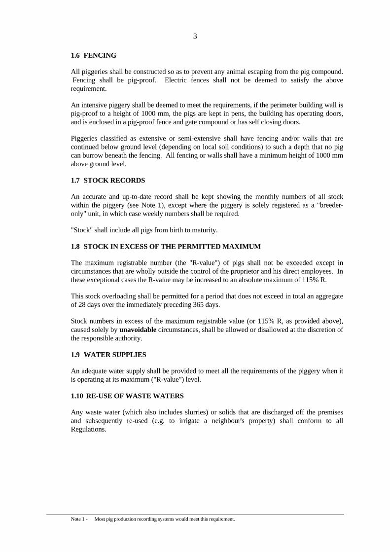
1.6 FENCING
All piggeries shall be constructed so as to prevent any animal escaping from the pig compound. Fencing shall be pig-proof. Electric fences shall not be deemed to satisfy the aboverequirement.
An intensive piggery shall be deemed to meet the requirements, if the perimeter building wall ispig-proof to a height of 1000 mm, the pigs are kept in pens, the building has operating doors,and is enclosed in a pig-proof fence and gate compound or has self closing doors.
Piggeries classified as extensive or semi-extensive shall have fencing and/or walls that arecontinued below ground level (depending on local soil conditions) to such a depth that no pigcan burrow beneath the fencing. All fencing or walls shall have a minimum height of 1000 mmabove ground level.
1.7 STOCK RECORDS
An accurate and up-to-date record shall be kept showing the monthly numbers of all stockwithin the piggery (see Note 1), except where the piggery is solely registered as a "breeder-only" unit, in which case weekly numbers shall be required.
"Stock" shall include all pigs from birth to maturity.
1.8 STOCK IN EXCESS OF THE PERMITTED MAXIMUM
The maximum registrable number (the "R-value") of pigs shall not be exceeded except incircumstances that are wholly outside the control of the proprietor and his direct employees. Inthese exceptional cases the R-value may be increased to an absolute maximum of 115% R.
This stock overloading shall be permitted for a period that does not exceed in total an aggregateof 28 days over the immediately preceding 365 days.
Stock numbers in excess of the maximum registrable value (or 115% R, as provided above),caused solely by unavoidable circumstances, shall be allowed or disallowed at the discretion ofthe responsible authority.
1.9 WATER SUPPLIES
An adequate water supply shall be provided to meet all the requirements of the piggery when itis operating at its maximum ("R-value") level.
1.10 RE-USE OF WASTE WATERS
Any waste water (which also includes slurries) or solids that are discharged off the premisesand subsequently re-used (e.g. to irrigate a neighbour's property) shall conform to allRegulations.

4
Note 1 - When land is assigned to both pigs and other stock, the true area occupied by pigs shall be determined after a reduction inarea has been made for the other stock according to the following scale.
(1) Locally accepted values or
(2) The following table
Stock No. per ha
Cattle Cow and calf Sheep or goats Poultry
1.51.0 7
225
2.0 PIGGERY CLASSIFICATIONS
2.1 PIGGERY CLASSIFICATIONS
A piggery shall be classified according to the space actually occupied, or designated foroccupation, by pigs (see Note 1).
ClassificationArea (Stocking Density)
m2 per pig
IntensiveSemi-intensiveSemi-extensive
Extensive
Fewer than 22 to 40
41 to 600More than 600
2.2 "BREEDER-ONLY" CLASSIFICATION
A "Breeder-only" piggery is defined as a piggery in which the progeny of breeding animals areremoved from the piggery at or before the age of 70 days. To qualify for this classification, the"breeder-only" piggery must be the only type of piggery on the property.
The R-value for a "breeder-only" piggery shall be five times the number of stock aged 71 daysand over (i.e. five times the normal breeding stock plus any "residual" progeny).

5
3.0 DEFINITIONS USED IN BUFFER ZONE TERMINOLOGY
The following definitions apply to all buffer zones:-
Bank full discharge level means the maximum level to which the water surface of a watercourse mayreach before overtopping of a bank begins.
"Breeder-Only" piggery means a piggery in which the progeny of breeding animals are removed fromthe piggery at or before the age of 70 days. There shall be no other type of piggery on the property.
Constrained winds means a wind having a speed of 6 knots or more which is forced to blow in aconfined path due to the presence of topographical features, e.g. a narrow valley.
Dispersed piggery means a piggery which, while being intensive in the nature of its operation, is soscattered in its layout that a piggery compound cannot be defined.
Domestic water supply channel means a water course which has been defined by the responsibleauthority as a "domestic water supply channel".
Farmhouse (not on the reference piggery property) means a residence on a property where stock arekept.
Fixed buffer distance means a distance, measured from a piggery or its associated operations, which isindependent of the size of this piggery.
Irrigation supply channel means a watercourse which contains water that is for non-potable purposes,and has been defined by the responsible authority as an "irrigation supply channel".
Isolated rural residence means any residence that is situated on land not defined as a rural residentialzone, residential area, or within a township boundary and not carrying out any agricultural activityinvolving stock.
Katabatic wind means a wind (or a component thereof) directed down the slope of a hill caused by ahigher density of air near the slope than that some distance away from that slope.
Land area used for waste disposal means land used for the application of treated or untreated wasteswhich may or may not be owned by the piggery operator.
Major watercourse means a watercourse which has been defined by the responsible authority as a"major watercourse".
Major water storage means a water storage for domestic purposes which has been defined by theresponsible authority as a "major water storage".
Piggery means any building, enclosure or yard in which 4 or more pigs are kept, bred, reared orfattened.
Piggery Compound means the area enclosed by a piggery perimeter and having a piggery referencepoint.
6
Note 1 - In Victoria, the zone will correspond with the boundary of rural residential-type zones shown on land-use planning maps.
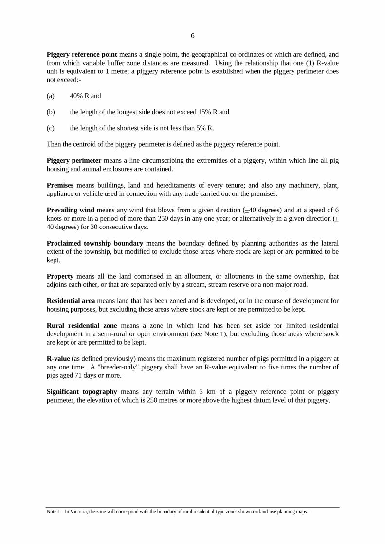
Piggery reference point means a single point, the geographical co-ordinates of which are defined, andfrom which variable buffer zone distances are measured. Using the relationship that one (1) R-valueunit is equivalent to 1 metre; a piggery reference point is established when the piggery perimeter doesnot exceed:-
(a) 40% R and
(b) the length of the longest side does not exceed 15% R and
(c) the length of the shortest side is not less than 5% R.
Then the centroid of the piggery perimeter is defined as the piggery reference point.
Piggery perimeter means a line circumscribing the extremities of a piggery, within which line all pighousing and animal enclosures are contained.
Premises means buildings, land and hereditaments of every tenure; and also any machinery, plant,appliance or vehicle used in connection with any trade carried out on the premises.
Prevailing wind means any wind that blows from a given direction (±40 degrees) and at a speed of 6knots or more in a period of more than 250 days in any one year; or alternatively in a given direction (±40 degrees) for 30 consecutive days.
Proclaimed township boundary means the boundary defined by planning authorities as the lateralextent of the township, but modified to exclude those areas where stock are kept or are permitted to bekept.
Property means all the land comprised in an allotment, or allotments in the same ownership, thatadjoins each other, or that are separated only by a stream, stream reserve or a non-major road.
Residential area means land that has been zoned and is developed, or in the course of development forhousing purposes, but excluding those areas where stock are kept or are permitted to be kept.
Rural residential zone means a zone in which land has been set aside for limited residentialdevelopment in a semi-rural or open environment (see Note 1), but excluding those areas where stockare kept or are permitted to be kept.
R-value (as defined previously) means the maximum registered number of pigs permitted in a piggery atany one time. A "breeder-only" piggery shall have an R-value equivalent to five times the number ofpigs aged 71 days or more.
Significant topography means any terrain within 3 km of a piggery reference point or piggeryperimeter, the elevation of which is 250 metres or more above the highest datum level of that piggery.

7
Standard piggery means a piggery that uses good management techniques and -
(i) the buildings of which are naturally ventilated and odours are, or can be, emitted from side-openings or roof-ventilators without treatment; and
(ii) the buildings of which are cleansed (manually or mechanically) of effluent from the confines ofthe building at least once a week; and
(iii) the effluent of which could be expected to be substantially anaerobic at the time of removal.
Stock means any bull, cow, ox, calf, stallion, mare, gelding, foal, ass, mule, camel, ram, ewe, wether,lamb, pig, goat, dog or other animal or bird (other than a cat, dog, or bird kept solely as a domestic pet).
Variable buffer zone distance means a horizontal distance measured between a piggery referencepoint, or piggery perimeter and specified residential complexes. The distance is (within certain limits)proportional to the R-value of the piggery.
Watercourse means any surface waters of the policy area both perennial and intermittent and includesany river, stream, reservoir, billabong creek, anabranch, canal, wetland, channel, lake, lagoon, dam,natural or artificial water course, bay, coastal or tidal waters, and excludes waters within wastetreatment systems, waters within enclosed water supply distribution systems, farm dams, private ponds,piped or underground drains and the interstitial water of sediments.
Watertable means the planar surface between the zone of saturation and the zone of aeration. It is alsoknown as the free water elevation, free water surface, groundwater level, groundwater surface,groundwater table, level of saturation, phreatic surface, plane of saturation, saturated surface, waterlevel, or water line. It shall not include a perched watertable.
Watertable-perched means the watertable or upper surface of a body of groundwater that is unconfinedand separated from an underlying main body of groundwater by an unsaturated zone. A perchedwatertable is also known as an apparent watertable.

8
4.0 BUFFER ZONE DIMENSIONS (DISTANCES) FOR A PIGGERY
4.1 FIXED AND VARIABLE BUFFER ZONES
Buffer zones are established around a piggery and consist of two parts -
(1) Fixed and
(2) Variable
A variable buffer zone shall have an assigned horizontal distance that is determined accordingto the size of the piggery and the nature of the surrounding conditions. These distances shall bemeasured from the piggery reference point, when provided; otherwise from the nearest point onthe piggery perimeter to a defined feature.
Variable buffer zones shall be established between the piggery (or pig unit) and the followingfeatures -
(a) Proclaimed township boundary (Zone 1A)
(b) Rural residential zone/residential area (Zone 1B)
(c) Isolated rural residence (Zone 2)
(d) Farmhouse (not on the same property as the piggery)(Zone 3)
In certain circumstances Zones 1A and 1B may be combined and then shall be referred to as Zone1.
4.2 REDUCTION IN VARIABLE BUFFER ZONE DIMENSIONS (DISTANCES)
A variable buffer zone dimension may be reduced only when the piggery achieves andmaintains conditions of a higher quality and efficiency compared with those prescribed for astandard piggery. The degree of reduction to be applied shall be determined according to theformula shown in section 4.6.
4.3 FIXED BUFFER ZONES (DIMENSIONS) FOR A PIGGERY
Any buffer zone whose dimensions are independent of the size of a piggery shall be defined as afixed buffer zone.
Fixed buffer zone distances shall be the least horizontal distance between a piggery building orarea designated for occupation by pigs, and each of the following features -

9
Note 1 - A sealed road for the purposes of this section shall include any public road that is sealed, in whole or in part, providesdirect access to the piggery and is within 2 km of the piggery reference point (or perimeter fence if the piggery isclassified as "dispersed" or "extensive").
Note 2 - This excludes unsealed roads carrying fewer than 50 vehicles a day and not subject to planned upgrading within two yearsby the responsible authority. Predicted increases in traffic flows generated by the proposed piggery shall not be includedin the 50 vehicle a day criterion. The minimum buffer distance for such roads shall be 50 m except where it can bedemonstrated that the road is effectively unused.
Note 3 - Other watercourses shall exclude those watercourses which, in the opinion of the responsible authority, are at an elevatedlevel or protected by banks or levees such that under flood conditions effluent or piggery contaminated waters will notenter the watercourse.
Note 4 - No open effluent channel shall be within 50 m of a property boundary.
Note 5 - For the purpose of the 3000 m fixed buffer distance a neighbouring piggery is defined as a piggery, or a combination ofpiggeries within 3000 m of the proposed piggery, with an R value of 500 or greater. The 3000 m fixed buffer is requiredfor new piggeries, and not for extensions to existing piggeries.
Public road - sealed (see Note 1) 200 m*
Public road - unsealed (see Note 2) 200 m*
Major water supply storage within its catchment area 800 m
Major watercourse and domestic water supply channel 200 m
Other watercourses (see Note 3) 100 m
Residence on the property 100 m
Dairy 100 m
Slaughterhouse 100 m
Property boundary (see Note 4) 20 m
Neighbouring piggery (see Note 5) 3000 m
* See also the special provision shown below.
The measuring point for a public road shall be any surface that has been specifically prepared tocarry traffic and shall include associated shoulders and footpaths.
The measuring point for a watercourse shall be the highwater mark formed when thewatercourse is at bank-full discharge level.
A neighbouring piggery requires a 3000 m buffer unless a legal association exists between thepiggeries, or a pig health status determined by an experienced piggery veterinarian is acceptedby the existing piggery's proprietors thereby providing a dispensation from the 3000 m fixedbuffer.
Where a dispensation of the 3000 m distance has been obtained for a neighbouring piggery, orwhere the application is for an extension to an existing piggery, the buffer zones of thecombined piggeries shall be determined by the responsible authority. The maximum buffershall not exceed the prescribed buffer for a dispersed piggery incorporating all piggeries within3000 m. The perimeter of the combined piggery shall be calculated as the dispersed piggery.
Roads - special provision
In exceptional circumstances, and at the discretion of the responsible authority these distancesmay be reduced by the same percentage value as determined in section 4.6 entitled "reduction invariable buffer zone dimensions (distances) for a piggery". It should be carefully noted that anysubsequent failure to maintain standards which permitted a buffer zone reduction will result innon compliance with the fixed buffer zone required for a public road.

10
4.4 CALCULATION OF DISTANCES FOR THE VARIABLE BUFFER ZONES OFA STANDARD PIGGERY
4.41 Introduction
Except in special cases (e.g. cases involving prevailing winds, significant topography;constrained winds, "breeder-only" units), which are described in subsequent sections, the bufferzone distance between a piggery reference point and a proclaimed township boundary shall becalculated using the formula:
1 R-value unit = 1 m.
Fractions of a metre shall be used, as defined below, for other specified residential categories. The formulae shall only be applied to piggeries having R-values in the range 2000 to 5000.
Zone Description Distance (m)
1A
1B
2
3
Piggery reference point to a proclaimed township boundary
Piggery reference point to a rural residential zone or residentialarea
Piggery reference point to an isolated rural residence
Piggery reference point to a farmhouse (other than on theproperty of the piggery)
1.00 R
0.75 R
0.25 R
0.20 R
4.42 Piggeries having R-values in the range 4 to 500
For any piggery having an R-value below 500, the 500 R-value shall be used. The maximumpiggery perimeter shall not exceed 200 m.
4.43 Piggeries having R-values in the range 501 to 2000
For any piggery having an R-value below 2000, the 2000 R-value shall be used. The maximumpiggery perimeter shall not exceed 800 m.
4.44 Piggeries having R-values in excess of 5000
For any piggery having an R-value in excess of 5000, a works approval is required from theEnvironment Protection Authority.

11
Note 1 - In Victoria, it is estimated that less than 5% of all existing piggeries have been established in locations where buffer zonedimensions would require modification due to these specific conditions. Although it is unlikely that many new piggerieswould be promoted in such areas it is necessary, for completeness, that this Code of Practice cover all potential situations.
4.45 Table of R-values and zones distances
The following table shows typical zone distances for R-values increasing in 500 unit steps. Foran intermediate R-value in the range 2000 to 5000 the respective zone columns may beinterpolated.
R-value(no. of pigs)
Zone 1A
(metres)Zone 1B
(metres)Zone 2
(metres)Zone 3
(metres)
Fewer than 500501 to 2000
2000250030003500400045005000
160020002000250030003500400045005000
100015001500187522502675300033753750
400 500 500 625 750 875100011251250
300 400 400 500 600 700 800 9001000
4.5 VARIABLE BUFFER ZONE DIMENSIONS FOR SPECIFIC CONDITIONS
Under certain meteorological or topographic conditions the buffer zones previously describedwill not apply (see Note 1). The buffer zones are modified when the following conditionsapply -
Prevailing wind conditions - see appendix 3
Constrained wind conditions - see appendix 4
Significant topography conditions - see appendix 5
4.6 REDUCTION IN VARIABLE BUFFER ZONE DIMENSIONS (DISTANCES)FOR A PIGGERY
A reduction, not exceeding 40% of "standard" piggery distances, may be sought on the variablebuffer zone distances (fixed buffer distances are unaffected). The reductions apply wherehigher-than-average standards on the piggery are designed and maintained at all times.

12
The responsible authority may decide not to permit a buffer zone reduction if the pig feedincludes, or may include, any liquid dairy by-products (e.g. whey) and/or the cooking of animalresidues (e.g. abattoir or poultry "inedible offal"/trimmings). See also the note at the end ofSection 4.73.
4.61 Reduction factors
Reduction factors based on odour emissions, noise, maintained supplies and management areshown on the following page. The factors are designated A to G (see table Page 13).
4.62 Reduction formula
Percentage reduction = 100 x [1 - (A x B x C x D x E x F x G)] of standard buffer zonedimensions (see Note 2 on the following page).
The maximum reduction shall NOT EXCEED 40%.

13
Note 1 - In Victoria, to be determined by the Environment Protection Authority.
Note 2 - This Code of Practice calls for a reasonably high standard at all piggeries, which is achieved by good management andcontrol of odour-generating procedures. A piggery scoring a negative reduction factor (ie. an increase) in variable bufferzone distances would not meet the requirements of this Code of Practice.
4.61 REDUCTION FACTORS
Designator Reduction Factor
A Emission to air from buildings(1) Ridge and side-ventilators (or side only)(2) Ridge-ventilators only(3) Ridge-ventilators plus trees (more than 10 m high) surrounding the piggery compound(4) Air-scrubbing (i.e. odour removal) of all building exhaust gases
1.000.95
0.900.20
B Effluent collection system within all pig buildingsFaeces, urine and other biological material removed from the confines of the buildings(1) Less than 6 hours(2) While essentially aerobic but in no case greater than 30 hours(3) Greater than 30 hours
0.750.901.00
C Effluent collection system outside all pig buildings (but within the piggerycompound)(1) Closed pipes (pig buildings to aerobic holding tank/pump well)(2) Open channels (pig buildings to aerobic holding tank/pump well)
0.951.00
D Effluent treatment system (within the piggery compound)(1) Anaerobic lagoon(s) (including all inlet pipes/channels)(2) Facultative lagoon(s) (including all inlet pipes/channels)(3) Aerobic lagoon(s)(4) Aerated lagoon(s) (aerobic surface layer over entire lagoon)(5) Series lagoons anaerobic/aerobic (or facultative)(6) Other treatment systems
1.000.950.600.751.00
(see Note 1)
E Noise(1) Maintaining noise recommendations (see section 6.1)(2) For each 3dB increase above noise recommendations
0.950.05 per 3dB
F Power supplies for ventilation and effluent handling and pumping(1) Reliable power supply (loss of supply for not more than an aggregate of 2 hours a week)(2) Power supplies (loss of supply in excess of 2 hours a week)
(3) Standby power supplies - full-load standby capacity(4) Standby power supply for each 25% reduction in full load standby capacity.
1.001.00 plus
0.01 per hour0.80
0.80 plus0.5 per 25%
G ManagementStock under surveillance - 24 hrs/day 12 - 12 hrs/day 6 - 11 hrs/day 1 - 5 hrs/day Less than 1 hr/day
0.900.951.001.101.20
Stock under surveillance shall mean that a person, qualified or competent to have charge of stock and deal with routine or emergency conditions as they arise, is monitoring the functions of that piggery.

14
GENERAL NOTE:
1. Under normal circumstances (i.e. those unaffected by restraining parameters such as prevailing winds) these buffer zones are radialscentred on the piggery reference point.
2. Where restraining parameters exist, zones 1A and 1B are reclassified as zone 1.
Example 1 - BUFFER ZONES
4.63 Piggery with radial buffer
Buffer zone
Z1A – Piggery reference point to a proclaimed township boundary
Z1B – Piggery reference point to a rural residential zone or residential area
Z2 -- Piggery reference point to an isolated rural residence
Z3 -- Piggery reference point to a farmhouse (not on the property of the piggery)
15
GENERAL NOTE:
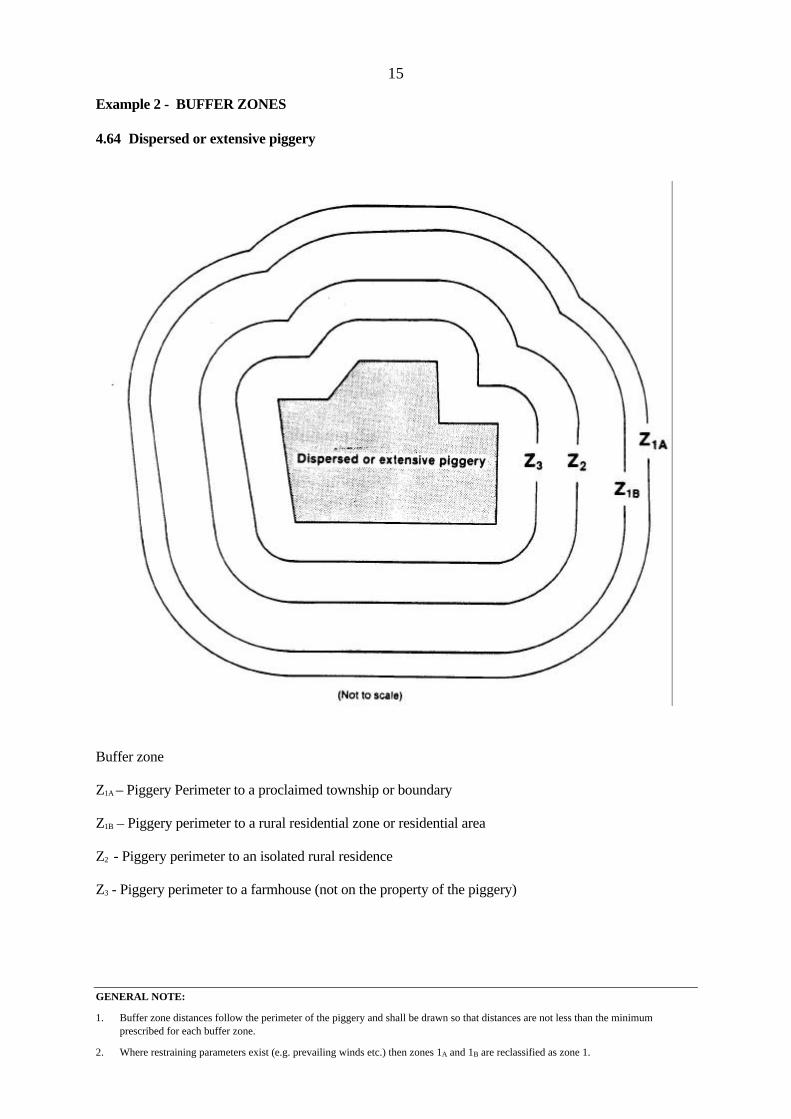
1. Buffer zone distances follow the perimeter of the piggery and shall be drawn so that distances are not less than the minimumprescribed for each buffer zone.
2. Where restraining parameters exist (e.g. prevailing winds etc.) then zones 1A and 1B are reclassified as zone 1.
Example 2 - BUFFER ZONES
4.64 Dispersed or extensive piggery
Buffer zone
Z1A – Piggery Perimeter to a proclaimed township or boundary
Z1B – Piggery perimeter to a rural residential zone or residential area
Z2 - Piggery perimeter to an isolated rural residence
Z3 - Piggery perimeter to a farmhouse (not on the property of the piggery)

16
Note 1 - Systems that have been approved as Category 5 are required to (at least) maintain the minimum approved specificationsand standards. Any alteration or failure of a system may lead to a reclassification to another category number or increasedbuffer distances.
4.7 BUFFER DISTANCES SURROUNDING EFFLUENT TREATMENT SYSTEMSOR LAND DISPOSAL AREAS
Buffer zones shall be established between all treatment units or land disposal areas andresidential or other nominated features. They are in addition to buffer zones for the piggery andare determined separately.
Distances are measured from the perimeter of the unit or system of units. In the case of landdisposal, distances are measured from the perimeter of the area being used (defined as the"wetted area"). The distances are of fixed value.
When effluent is to be spread or discharged, account shall be taken of actual and forecast windconditions so as to prevent all such effluent being carried by the wind beyond the "wettedperimeter".
When any effluent material (liquids, solids or slurry) is taken across a property boundary oralong public roads, it shall be in enclosed containers or pipes so as to avoid causing a nuisance.
4.71 Effluent treatment systems (categories)
Effluent handling systems shall be classified into five categories. The buffer zone distancesrequired for each category are shown in the table on page 18.
Category 1 - Sludge drying beds
- Drying lagoons
Category 2 - Anaerobic lagoons
- Barrier ditches
Category 3 - Facultative lagoons
- Solids/liquids separators
Category 4 - Aerobic lagoons
Category 5 - Advanced-system package-treatment plant having totally enclosed or fullyaerated units (see Note 1).
Any system in Category 3, 4 or 5 that is located within the perimeter of any piggery having apiggery reference point shall be deemed to satisfy the buffer zone requirements of this section.
Where an effluent handling system fits into more than one category the more (or most) stringentcategory shall apply.

17
4.72 Effluent disposal to land (categories)
Category 1 - All effluents are discharged or projected to a height in excess of 2 metres aboveground level.
- Liquid effluents in which water remains visible on the soil surface for periodsin excess of 1 hour.
- Separated solids that remain on the soil surface for more than 24 hours (i.e. arenot immediately ploughed in).
Category 2 - Mechanical spreaders (in combination with "ploughing-in" type equipment)and downward discharge nozzles. The discharged material shall not beprojected to a height in excess of 2 metres above ground level.
Category 3 - Land receiving effluents that are "fresh" (i.e. those that are less than 12 hoursold) and having a solids content of no more than 5%.
- Aerated effluents from which at least 75% solids have been removed.
- Any effluent with a B.O.D. value of less than 2500 mg/l.
Category 4 - Discharge by injection directly into the soil (to a depth of not greater than 0.4metres) and at a rate not exceeding either the hydraulic or NPK limitsdetermined for the local soil type(s).
Category 5 - Effluent from a tertiary treatment system.
- Packaged treatment units producing effluent of a tertiary quality (that meet andmaintain the manufacturer's specifications). (see Note 1).
Where more than one category of disposal to land is used the more (or most) stringent categoryshall apply.

18
Note 1 - When liquid dairy by-products (e.g. whey) or solids/liquids from the cooking of animal residues are, or may be, present inthe piggery effluent the responsible authority may decide to classify the effluent treatment and/or effluent disposalsystem(s) as Category 1.
Note 2 - No non-mobile treatment facility shall be closer than 50 m of a property boundary.
4.73 Table of Buffer Distances Surrounding Effluent Treatment Systems or LandDisposal Area
CATEGORY NO. (see Note 1)DISTANCES IN METRES
1 2 3 4 5
Proclaimed township
Residential area Rural residential area
Isolated rural residence
Neighbouring farmhouse
Property boundary (see Note 2)
Major water supply storage within its catchment area
Domestic water supply channel
Watercourse
Public highway (carrying in excess of 50 vpd excluding traffic to the piggery)
2000
1500
1000
500
500
20
800
200
100
200
1500
1000
500
500
400
20
800
200
100
200
1000
500
400
400
300
20
800
200
100
150
500
200
200
200
100
20
800
200
100
50
**See
Below
Distances shall be measured from the perimeter of the area used for handling or disposal ofeffluent.
** Distances in Column 5 are subject to determination by the responsible authorities.

19
5.0 DESIGN REQUIREMENTS FOR BUILDINGS
5.1 GENERAL
Any structure erected to provide shelter for pigs housed in extensive or semi-extensive piggeriesshall, at the time of construction, be of materials having a service life of at least 5 years unlessotherwise approved by the responsible authority.
Intensive and semi-intensive piggeries shall, at the time of construction, be constructed ofmaterials having an expected service life of at least 10 years. This shall apply to all materialsused for foundations, external walls, roofs, columns, beams and trusses. Roofs shall beweatherproof and may be insulated.
Flooring and other structures shall be designed to permit the efficient removal of all faeces andurine. Removal may be on either a continuous or intermittent basis.
5.2 INTENSIVE AND SEMI-INTENSIVE PIGGERY UNITS
Exterior and structural walls, which are in contact with pigs, shall be constructed of pig proofmaterial and extend to a height of at least 1000 mm above floor level. The wall and drainagesystem will be constructed so as to avoid the discharge of pig wastes or pig waste contaminatedwaters to adjacent areas.
All cavity walls shall be constructed in such a manner as to deter the harbouring of vermin andbirds.
Floors (including manure channels when provided) shall have an upper surface datum that is notless than 500 mm above the regional watertable.
All floors shall be of a sound and impervious material and be damp-proof.
5.3 EXTENSIVE AND SEMI-EXTENSIVE PIGGERY UNITS
All structures will be designed to minimise the likelihood of harbouring vermin and birds.
5.4 DRAINAGE SURROUNDING A PIGGERY
Where the topography surrounding the piggery causes surface water to drain towards anybuilding within the piggery unit an interceptor channel may be provided to accept allstormwater. Stormwater thus collected shall either -
(a) be discharged by the most suitable means, either to storage, or direct to land, accordingto piggery unit design, or
(b) be considered as part of the piggery effluent and all effluent design systems shallincorporate the estimated peak surface water run-off.
Clean stormwater may be discharged direct from the property.

20
Note 1 - Statutory Rules 1975 No. 133 Harmful Gases, Vapours, Fumes, Mists, Smokes and Dusts (Amendment) Regulations Government of Victoria.
Note 2 - In Victoria reference should be made to the current requirements under the Victoria Building Regulations. Thesestandards shall be used and not those specified by the Standards Association of Australia.
Contaminated stormwater from roofs, open yards and natural drainage shall be considered asforming a part of the piggery effluent and the effluent system shall be designed to meet peakflow conditions.
5.5 ENVIRONMENTAL CONTROL AND WORKING CONDITIONS IN ENCLOSEDSPACES
Ventilation shall be provided at all times to prevent a build-up of noxious odours and toxicgases. Prescribed levels (see Note 1) for dust, noxious and toxic gases shall not be exceeded.
Headroom in all areas of buildings and other structures where stockmen are regularly requiredto work, and in all passageways, shall not be less than 2030 mm (see Note 2). This shall applyto all overhead projections such as conduits, lighting sources, pipes and sprinkler systems. Distances shall be measured vertically from the floor surface.

21
Note 1 - In Victoria see Statutory Rules (1978) No. 269 Health (Hearing Conservation) Regulations 1978.
6.0 OPERATING REQUIREMENTS
6.1 NOISE
6.11 Hearing conservation
Noise levels for those working within the piggery unit are mandatory limits. These are asfollows -
Where an employee is engaged in any process or occupation and either -
(i) the daily noise dose of the employee exceeds 1.0; or
(ii) the employee is at any time exposed to a noise level exceeding 115dB (A) Slow; then
the employer shall take action to ensure that the exposure of any employee does not exceed thelimits shown in (i) and/or (ii). The methods used to reduce noise shall be in accordance withthose laid down by Statutory Rules (see Note 1).
All persons hearing protectors shall comply with Australian Standard AS1270.
6.12 Other limits
The noise limits for a residence (other than a residence on the property) are mandatory and arespecified for quiet rural areas. Where the piggery is located in areas with higher backgroundnoise levels, higher limits may apply as specified by State Environment Protection Policy(Control of Noise from Industry, Commerce and Trade) No. N-1. Compliance with the noiselimits shall be assessed at a point within 10 metres of the external walls of a residentialbuilding.
The limits applying to the property boundary shall be mandatory only when a reduction inbuffer zone distances is sought by the proprietor of a piggery.
Noise Limits
PropertyResidence Boundary
* Day (0700 - 1800 hrs) 45 dB(A) 50 dB(A)
Evening (1800 - 2200 hrs) 37 dB(A) 45 dB(A)
Night (2200 - 0700 hrs) 32 dB(A) 40 dB(A)
* On Sundays and public holidays between 0700 - 1800 hrs and Saturdays between 1300and 1800 hours the evening noise limits shall apply.

22
Note 1 - In Victoria, reference should be made to the "Guidelines for Storage and Disposal of unwanted Agricultural Chemicalsand Chemical Containers" published by the Environment Protection Authority and the Department of Agriculture andRural Affairs.
Note 2 - Swill means "food refuse" and includes
(a) the meat, fat, bones, blood, eggs or viscera of any stock; and
(b) any other matter, product or substance which contains or has been in contact with any such meat, fat, bones, blood,eggs or viscera.
Note 3 - Certain exemptions to the prohibition of food refuse fed to pigs are contained in Stock Diseases Act, 1968 (No. 7724)Section 15, Government of Victoria.
6.2 GENERAL SAFETY
6.21 Entry into confined spaces
No person shall enter an enclosed space used as a pit or manure storage area unless equippedwith a respirator and wearing a safety line. A "safety observer" shall also be in attendance butremain outside the possible danger area. All enclosed pits shall display prominent warningsigns as follows -
6.3 FLIES AND FLY-BREEDING
All reasonable steps shall be taken to minimise fly-breeding.
6.4 STORAGE AND DISPOSAL OF CONTAINERS AND TOXIC SUBSTANCES
Care shall be exercised in the storage and disposal of containers of such materials to preventany toxic substance entering any watercourse, either directly or by run-off from land (see Note1).
6.5 FEED AND FEED-STORAGE
Feed shall not be left on floors, troughs, bowls, ground or general feeding areas in such a waythat it becomes offensive. Feed and feed storage areas shall not encourage the breeding ofvermin.
Swill-feeding shall not be permitted (see Notes 2 and 3).
Animal offal shall be boiled for at least one hour before being fed to pigs. All inedible mattershall be removed within 24 hours and either incinerated, removed from the premises by a properdisposal operator, or buried.
DANGER - GAS
NO SMOKING - NO NAKED FLAME
23
Note 1. In Victoria, the Environment Protection Authority issues Air Discharge Licences.
When wrapped food, condemned for human consumption, is fed to pigs all non-biodegradablewrapping material shall be removed either before feeding or within 24 hours of consumption. All such wrapping material shall be disposed of by incineration, burial or removal so that it willbe neither offensive visually nor a hazard to wildlife.
All materials used in the construction of containers for feed or water (including bins, chutes andpipes) shall be free of sharp edges or projections that could cause injury to personnel oranimals. (Any such materials that may become accessible to pigs shall be "pig proof").
6.6 DISPOSAL OF DEAD PIGS AND OTHER BIOLOGICAL MATERIAL
Dead pigs, immediately upon discovery, shall be removed from the proximity of other pigs. Where it is impracticable to dispose of the carcases immediately they shall be temporarily heldin an area inaccessible to animals, vermin and birds. Disposal in an approved manner shall becarried out within 24 hours of death.
Biological material (e.g. afterbirths) shall also be destroyed or removed and held in an areainaccessible to animals, vermin and birds until destroyed.
Acceptable disposal methods (in order of preference), shall be -
(a) Removal to a disposal/rendering works
(b) Incineration
(c) Burial
Incineration shall conform to local fire regulations and restrictions.
When burial methods are used the excavated trench or pit shall not be deeper than 2000 mm or500 mm above the watertable, whichever is the lesser value.
Carcases and other biological matter, when placed in the burial trench, shall be immediatelycovered with 500 mm of soil. A minimal final cover for all trenches and pits shall be 500 mmof compacted topsoil.
6.7 INSTALLATION OF EQUIPMENT
All equipment, mechanical and/or electrical shall be installed, commissioned and operated inaccordance with current safety regulations.
6.8 OPERATION AND MAINTENANCE OF EQUIPMENT
Effluent handling equipment will be maintained in effective working order.
6.9 INCINERATION
Incinerators shall, if required, conform to air-quality standards and regulations (see Note 1).

24
6.10 LAGOONS
Lagoons shall be constructed with a low permeability liner of adequate thickness and operatedwithin a minimum freeboard of 500 mm and maintained to ensure wastes do not contaminatesurface or ground waters.
Fences shall be provided to prevent easy access by farm stock and humans.
All lagoons having a depth of 2 metres or more shall have prominent warning notices placedaround the perimeter fence, reading -
All ramps to lagoons or pits shall be designed to support the attendant service vehicles withoutdamaging the structure of the lagoon.
DANGER - DEEP WATER

25
Note 1 The suggested maximum NPK loadings are:-
N - 350 kg/ha/yr
P - 150 kg/ha/yr
K - 200 kg/ha/yr
7.0 DISPOSAL OF EFFLUENT
7.1 DISPOSAL TO LAND
Effluent disposal to land (with or without pre-treatment) shall be in accordance with thefollowing -
1. There shall be no run-off of wastes or of stormwater contaminated by wastes from theproperty. Stormwater uncontaminated by wastes may be discharged off-site.
Precautions shall be taken during periods of bad weather to prevent any irrigatedeffluent being carried downslope towards residences, watercourses, and prohibitedflood plain areas.
2. No polluting material shall be permitted to enter any groundwater (including boreholes, mineshafts, wells or infiltration basins or other similar structure specificallydesigned for direct injection to groundwaters) which is detrimental to the beneficial useof ground waters or surface waters.
3. The hydraulic loading of each and every soil type shall not be exceeded.
4. The NPK loading on any soil shall not be exceeded (see Note 1), or such values that arenormally accepted as being used by the designated vegetative cover.
7.2 SOIL-TESTING (INTRODUCTION)
Soil-testing, if required, determines:
(1) the permitted hydraulic loading, such that all the waste water applied to the land will betaken up by the soil moisture deficit and/or evaporated through evapotranspiration.
(2) that all the applied nutrients will be taken up by the soil deficiency (if any) and the type,or proposed type, of vegetative cover. The responsible authority will normally acceptthe standard NPK loading as shown in Note 1 below, or such values that are normallyaccepted as being required by the designated vegetative cover.
Reference shall be made to the responsible authority(ies) to determine whether specific localconditions apply to the hydraulic and/or nutrient loadings proposed.
7.3 SOIL-TESTING FOR HYDRAULIC LOADING
Soil-testing shall only be required when the actual disposal area available (i.e. area remainingafter all buffer zones, areas for building, lagoons and unusable ground has been excluded) isless than 1 hectare per 35 pigs.

26
Note 1 - Soil testing could include other approved tests, e.g. Talsma test.
The number of test sites selected within the disposal area shall be sufficiently representative ofeach of the characteristic soil types identified.
Unless specified to the contrary (see Note 1), in writing, by the responsible authority the testsshall be as follows -
(a) Effluent application onto the soil surface - Double-ring infiltrometer.
(b) Effluent application into the soil (direct injection) - Percolation test.
These tests shall be carried out according to the specifications shown in Appendix 1 andAppendix 2.
Acceptable figures for both tests shall be in the range 5 mm/hr to 150 mm/hr. When the rateexceeds 150 mm/hr the responsible authority shall require further investigations to be made todetermine the capability of the soil to retain NPK from the effluent.
7.4 DISPOSAL OF BOULDER-STREWN LAND
A boulder shall be defined as any rock or stone having dimensions in excess of 500 mm whenmeasured along its longest axis and 400 mm on an axis perpendicular to that axis.
A significant incidence of boulders shall be defined as any land containing, on its surface,boulder coverage in excess of 20%.
When boulder-strewn conditions apply the land area required for disposal of effluent shall beincreased in direct proportion to the actual area covered by boulders.
Disposal to boulder-strewn land shall not be permitted when the area covered by bouldersexceeds 80% of the total area.
7.5 DISPOSAL OF EFFLUENT VIA A BOREH0LE
No effluent that contains, or may contain water contaminated by pigs or pig effluent (e.g.contaminated stormwater), shall be disposed of below ground level through a borehole.
7.6 COMBINATION OF EFFLUENT WITH OTHER WATERS
7.61 Sullage
Sullage (waste water from kitchens, showers and washing facilities but not sewage) may bemixed with piggery effluent before treatment or disposal.

27
7.62 Sewage
No sewage shall be added to piggery effluent except where both are immediately discharged toa public sewer and there is no possibility of access to sewage or sewage mixture by man oranimal.
7.63 Water derived from irrigation channels or watercourses (including boreholes)
A hydraulic disconnector device shall be installed to prevent at all times the backflow ofeffluent that may arise should a malfunction of equipment or abnormal conditions occur.

28
APPENDIX 1
DOUBLE RING INFILTROMETER TEST
EquipmentDia.
(mm)Length(mm)
Thickness(mm) Finish
Measuring cylinder
Buffer cylinder
Driving plate
300
500
400
300-500
200
-
2*
-
12
Smooth
-
**
* A greater thickness may be used if a ground cutting-edge is provided.** Lugs on the underside, to centre the driving plate onto the measuring cylinder.
Tamping Hammer - Suitable for driving the measuring cylinder. Recommended weight 10 kg.Water Supply - Sufficient for the full test procedure.Measuring Device - Hook Gauge or manometer or automatic flow/stage recorder.
Method
(i) Select a site which is representative of the general soil in the area of the test.
(ii) Press the measuring cylinder into the soil using the driving plate and hammer, as required, todrive the cylinder vertically into the soil to a depth of approximately 100 mm. (Note: irregulardriving (side to side penetration) will lead to poor bonding between the cylinder wall and thesoil).
(iii) Press the buffer cylinder into the soil to a depth of 50 to 100 mm and approximately concentricwith the measuring cylinder.
(iv) Fill the buffer cylinder to approximately 50 mm depth and maintain at least 25 mm throughout thetest.
(v) Protect the surface of the soil at the bottom of the measuring cylinder with a piece of cloth, thenfill the cylinder with water to a depth of approximately 75 mm.
(vi) Having removed the soil protecting cloth, make a measurement of the water surface elevationusing a hook gauge (or manometer or automatic flow/stage recorder). Record the elevation andnote the time.
(vii) Make additional hook gauge measurements at intervals (typically at 1, 3, 5, 10, 20, 30, 45, 60, 90,120 minutes and hourly thereafter). The intervals shall be such that the water level does not fallmore than 25 mm between successive measurements. Continue until the rate of intake to the soilis almost constant.
(viii) When the water level in the measuring cylinder has dropped by 25 to 50 mm add sufficient waterto return the water surface to (approximately) its initial elevation. Record the elevation justbefore, and again just after filling. This time interval should be as short as practicable. (Theassumption made in the theory is that the refilling is instantaneous. Alternatively a constant headdevice incorporating a flow measuring device or automatic flow stage recorder may besubstituted.

29
GENERAL NOTE - Cohesive soils may also be tested using a liner as specified for sandy soils.
APPENDIX 2
PERCOLATION TEST
The site for the proposed disposal area shall be tested in accordance with the percolation test shownbelow.
Sufficient test holes shall be established to effectively represent the soil conditions over the site.
Where two percolation tests on the same hole differ by more than 20% the test shall be repeated untilconsistency of results is obtained.
After the percolation rate of all test holes has been computed any test results that differ by more thanthree standard deviations from the remainder shall be discarded. The arithmetic mean of the acceptabletest results shall be used as the percolation rate for the disposal area.
Where there are significant changes in soil types over the proposed disposal area, the percolation rate foreach sub-area shall be determined separately.
The soil percolation test requires that a hole shall be augered vertically into the soil at the test site andprepared in a specified manner. After thorough wetting, the hole shall be filled with water to aprescribed depth and the rate at which the water falls (determined by measuring the fall over a givenperiod of time) shall provide an indication of the soil hydraulic conductivity.
In some soils (notably sandy soils) collapse of the sides of the hole shall be prevented by augering anoversize hole and inserting a perforated liner tube.
The following apparatus will be required -
(a) Soil auger, hand operated (i) 100 mm dia. (cohesive soils)
(ii) 150 mm dia. (sandy soils) and
(b) Perforated liner tube 100 mm outside diameter (if required) and
(c) Coarse sand or fine gravel and
(d) Float-gauge or tape measure and
(e) Watch and
(f) Reference marker and
(g) Water container of known capacity or a constant head device.
Preparation of holes for cohesive soils (no liner required)
1. a 100 mm dia. auger is used. The hole is prepared by digging carefully to the subsoil (or 300 mm)but not exceeding 500 mm. Where shallow soil (less than 300 mm) extends over a rocky base, thehole shall be prepared to rock level. Holes shall be vertical.
Care shall be taken to avoid the use of augers that may compact or smear the soil surface with oils orgreases.
2. The bottom and sides of the hole shall be scraped carefully, with a hand-rake or coarse wire brushto provide as natural a soil interface as possible. All loose material shall be removed from thebottom of the hole.
30
3. Course sand or fine gravel shall be added to a depth of 50 mm in the base of the hole to preventsealing of the bottom by scouring or sediment.
Preparation of holes for sandy soils (liner required)
1. A 150 mm dia. auger is used. The hole is prepared by digging carefully to the subsoil (or 300mm) but not exceeding 500 mm. Where shallow soil cover (less than 300 mm) extends over arocky base, the hole shall be prepared to rock level. Holes shall be vertical.
Care shall be taken to avoid the use of augers that may compact or smear the soil interface.
2. The bottom and sides of the hole shall be scraped carefully with a hand-rake or coarse wire brushto provide as natural a soil interface as possible. All loose material shall be removed from thebottom of the hole.
3. The perforated liner shall be inserted vertically into the hole, and the gravel or other supportingmaterial shall be placed carefully between the outside of the line and the hole wall.
4. Coarse sand or fine gravel shall be added to a depth of 50 mm in the base of the hole to preventsealing of the bottom by scouring or sediment.
Percolation test
1. The hole shall be pre-soaked to ensure saturation and swelling of the soil. This requires that thehole shall be filled with clean water to a minimum depth of 150 mm for at least one hour. Forclay soils, soaking shall take place for a minimum of 24 hours, and the hole shall be topped up asnecessary. For sandy soils containing little or no clay the swelling procedure is not essential. Topping up is most easily achieved if a constant head device is available.
2. The water level shall be adjusted to 150 mm.
3. The drop in water level shall be measured for two 30 minute periods. Water shall be added at theend of each test as required to maintain a depth of 150 mm. Where the water seeps away rapidly,as in sandy soils, the test may be carried out over a reduced period of 10 minutes.
Repeatability of percolation tests
Percolation tests provide a simple and reasonably effective means of obtaining an indication of thepercolation rate of soil. The five major sources of error (compaction of wall sides, measurements,collapse of the test hole, depth of water added to the hole, and the hole diameter) can be considerablyreduced by the use of a perforated liner tube and a constant head device. The fall rate is then measuredby the water level in the device.
Calculation of percolation rate
The percolation rate is calculated by taking the lower rate of fall of the two results to determine the ratein millimetres per hour.

31
APPENDIX 3
DETERMINATION OF BUFFER ZONE DISTANCES WHEN PREVAILING WIND CONDITIONS APPLY
(1) Piggeries classified as having a piggery reference point
Zones 1, 2 and 3 shall be determined with reference to the diagram on the following page asfollows -
(a) The upwind section of each zone shall be arcs of circles of radii Y1, Y2, Y3 centred on thepiggery reference point. The values of Y1, Y2, Y3 shall be determined from theaccompanying table according to the size of the piggery.
(b) The downwind section of each zone shall be arcs of the circles of radii Z1, Z2, Z3 centred onpoints P1, P2, P3. These points shall be located on a line orientated in the direction of theprevailing wind and passing through the piggery reference point. The points P1, P2, P3 shallbe spaced distances of D1, D2, D3 respectively from the piggery reference point and thevalues shall be determined from the accompanying table according to the size of thepiggery.
(c) Straight lines shall join each arc that defines a particular zone. These lines shall form atangent to each arc.
Buffer Zone Description
Zone 1 Isolation distance to a proclaimed township boundary or rural residential area zone or residentialareas.
Zone 2 Isolation distance to an isolated rural residence.
Zone 3 Isolation distance to a farmhouse (not on theproperty of the piggery).
Zone 1 is associated with distances Y1, D1, Z1
Zone 2 is associated with distances Y2, D2, Z2
Zone 3 is associated with distances Y3, D3, Z3
R-VALUEY1
(m)Y2
(m)Y3
(m)D1
(m)D2
(m)D3
(m)Z1
(m)Z2
(m)Z3
(m)
Less than 2000 Use 2000 R-value 500 400 300 Use 2000 R-value
2000 2000 500 400 1000 500 400 2000 500 400
3000 2500 650 500 1500 650 500 3000 750 600
4000 3000 750 600 2000 750 600 4000 1000 800
5000 3500 900 700 2500 900 700 5000 1250 1000

32
Example:
BUFFER ZONE DISTANCES WHEN PREVAILING WIND CONDITIONS APPLY(PIGGERY HAVING A PIGGERY REFERENCE POINT)
Distances Y1 Y2 Y3: are radial and centred on the piggery reference point. (For a dispersed piggeryunit these zones follow the perimeter of the piggery area and have the samerespective values Y1 Y2 Y3).
Distances Z1 Z2 Z3: are down-wind of the piggery unit and are centred on points the distances of whichare D1 D2 D3 respectively from the piggery reference point.

33
GENERAL NOTE - When such a piggery is located in a valley having constrained winds (see Appendix 4) the extreme points in each of thetwo wind directions (defined as P and P1) shall be determined and distances D1 D2 D3 measured from these two pointsto determine the respective centres of the zones Z1 Z2 Z3.
(2) Piggeries classified as dispersed or extensive
Zones 1, 2 and 3 shall be determined as follows -
(a) A line shall be determined so that it is parallel to the direction of the prevailing wind. Thisline shall bisect the area defining the dispersed or extensive piggery.
(b) The extreme downwind boundary or point of the piggery area shall be determined and aperpendicular projection made onto the line defining the prevailing wind. This point "P"shall form the measuring point for distances D1, D2, D3 which in turn locate points P1, P2, P3,as described in the last section headed "Piggeries classified as having a piggery referencepoint".
(c) The downwind section of each zone shall be arcs of circles of radii Z1, Z2, Z3 centred onpoints P1, P2, P3. The values for D1, D2, D3 and Z1, Z2, Z3 shall be determined according tothe preceding table.
(d) The upwind section of each isolation zone shall have the value that would have applied hadthere been no prevailing wind.
(e) Straight lines, tangential at the points of contact, shall join the downwind arcs to therespective upwind buffer zone boundaries.
Example: BUFFER ZONES FOR A DISPERSED PIGGERY IN PREVAILING WINDCONDITIONS.
The line parallel to the direction of the prevailing wind shall divide the piggery area into two equalparts.
A perpendicular shall be dropped from the extreme downwind point of the piggery area to the describedline to define a point P.
Distances D1 D2 D3 shall be measured from point P to determine the centres for the radials Z1 Z2 Z3.

34
GENERAL NOTE - The minimum Y1 Y2 Y3 values shall be maintained.
APPENDIX 4
DETERMINATION OF BUFFER ZONE DIMENSIONS WHEN CONSTRAINED WIND CONDITIONS APPLY
(A constrained wind has a speed of 6 knots or more and is forced to blow in a confined path because ofthe presence of topographical features, e.g. a narrow valley).
The wind must blow in one direction (i.e. "up-valley" or "down-valley") for either -
(i) 30 consecutive days in any one year; or
(ii) an aggregate of 100 days in any one year.
The Buffer zone dimensions shall be determined as follows -
(a) Axes shall be established that follow the general directions of the valley and pass through the piggery reference point, or,in the case of dispersed piggery, the extreme points "P" and "P1" (as defined in the previous section), for both the "up-valley" and "down-valley" sides of the piggery.
(b) The dimensions and profile of the buffer zones shall be determined in the same manner as that for prevailing windconditions (see previous sections). The profile shall be "mirrored" about a line that is perpendicular to the topographyaxis (or axes) and also passes through the piggery reference point (or points "P" and "P1" as appropriate). The "up-valley" and "down-valley" buffer profiles shall be similar in shape.
(c) Care shall be exercised to ensure that the minimum isolation distances are maintained.
Example: BUFFER ZONE DIMENSIONS WHEN CONSTRAINED WIND CONDITIONSAPPLY.
The Axes A and B: These shall follow the general direction of the valley.
It should be noted that these two axes need not necessarily be collinear but may be inclined to each otherif this provides a better "fit" to the general topography of the valley.

35
APPENDIX 5
DETERMINATION OF BUFFER ZONE DIMENSIONS WHENSIGNIFICANT TOPOGRAPHY CONDITIONS APPLY
When a piggery is to be located in the vicinity of significant topography (i.e. where surrounding hill(s)exceed 250 m above the piggery height datum and the 250 m contour is within 3 km of the piggery) thefollowing shall apply -
Case 1 - Piggery surrounded by significant topography on two or more sides.
Case 2 - Piggery having significant topography on one side only.
Case 1
The appropriate R-value buffer zone shall apply, as shown in section 4.45 or in Appendix 3, (i.e. thestandard buffer zone or the prevailing winds buffer zone). Where a zone boundary intersects thesignificant topography contour line the zone boundary radial shall be truncated at that point and the zoneboundary shall then follow the contour line until further intersection(s) with the zone boundary radialare made. An example is given on page 37.
Case 2
(i) If the piggery lies closer than 3 km to the significant topography contour of an isolated hill thefollowing shall apply:
For each 1 km reduction in the distance between the piggery and the significant contour line, theZ1 zone distance shall be increased by 500 m up to a maximum of 6500 m and zones Z2 and Z3
distances proportionately increased. These values are shown in the table on the following page.
When significant topography contour is in excess of 3 km from the piggery no adjustment of theappropriate zone boundary patterns is required. When a zone boundary radial intersects thesignificant topography line the radial shall be truncated at that point and the zone boundary shallthen follow the contour line until further intersections with the zone boundary radial are made.
(ii) Piggery in the vicinity of an isolated hill:
The provisions made for Case 2 (i) shall apply but where the hill is limited in extent the zoneboundaries following beyond the significant topography contours shall be determined at the cutoff lines drawn from a specified point to extreme points on the significant topography contour.
The specified point(s) shall be -
(a) Piggery reference point or
(b) Extremities of the dispersed piggery. Such points shall be selected to give the LARGESTzonal area.
Examples of case 2 (i) and (ii) are given on page 38.

36
a TABLE: SPECIAL BUFFER ZONE DISTANCES FOR A PIGGERY IN THE VICINITY OF AN ISOLATED HILL
Distance toSignificant Topography 3 km 2 km 1 km 0 km*
R-VALUEZ1 Z2 Z3 Z1 Z2 Z3 Z1 Z2 Z3 Z1 Z2 Z3
(metres) (metres) (metres) (metres)
Less than2000
2000
3000
4000
5000
2000
2000
3000
4000
5000
500
500
750
1000
1250
400
400
600
800
1000
2000
2000
3500
4500
5500
500
500
875
1125
1375
400
400
700
900
1100
2500
2500
4000
5000
6000
625
625
1000
1250
1500
500
500
800
1000
1200
3000
3000
4500
5500
6500
750
750
1125
1375
1625
600
600
900
1100
1300
* Included for interpolation purposes only.
A linear interpolation between successive pairs of values may be made.

37
GENERAL NOTE: This example also shows the effect of significant topography acting as an acceptable screen on the spur of land to thenorth-west of the piggery.
The zone boundaries Z2 and Z3 are further truncated on the radial line (shown = = = ) centered on the piggery referencepoint and tangential to the spur of land.
(If the piggery has been dispersed or extensive the buffer zones would not be circles but follow the perimeter of the pigarea and the line (shown - - - ) would then be drawn from the extreme point of the area that gave the GREATEST zonalarea)
Example: BUFFER ZONES FOR PIGGERIES SURROUNDED BY SIGNIFICANTTOPOGRAPHY ON TWO OR MORE SIDES
(Diagrammatic and not to scale)
Significant topography contour (250 metres above piggery datum)
Zone boundaries are (in this example) radial from the piggery reference point (shown +)
Zones are truncated at the significant topography contour.

38
Example: PIGGERY (HAVING A PIGGERY REFERENCE POINT) IN THE VICINITYOF AN ISOLATED HILL
Example: DISPERSED PIGGERY IN THE VICINITY OF AN ISOLATED HILL